energy switch: a home-automation
TRANSCRIPT

Energy Switch: a Home-Automation System for Renewable Energy Self-Consumption Optimization
Daniele Sora
Technical Report n. �3, 2015
ISSN 2281-4299

Energy Switch: a Home-Automation System for
Renewable Energy Self-Consumption Optimization
Daniele Sora
November 11, 2015
Keywords:Smart Grid, Renewable Energies, Home automation, Energy Management
Abstract
One of the biggest problem regarding the distributed production ofrenewable energy is the effective employment of the produced energy.Usually, this energy is reintroduced in the grid with a disadvantagefor the producer. In this scenario, we propose an approach that aimsat exploiting the entire energy production reintroducing into the gridonly the part in excess. The proposed solution is based on a device,called energy switch, that enables a change of the electric energy sourceof a system such as one linked to both photovoltaic and classical en-ergy grid. This operation needs many considerations for warranting acorrect energy management and avoiding energy lacks potentially dan-gerous for the appliances. In particular the system has to be able torecognize the situations in which it is possible to use the cheaper sourcewithout causing an energy lack to the system. In the proposed solu-tion, the input data for the system are given by the OMeter stationsdeveloped by Over Technologies, a spin-off of Sapienza University. Aworking prototype of the energy switch has been built for future em-pirical test about its efficiency. The system reduces the problem ofchoosing which lines to connect to which energy source to the knap-sack problem. The performance of the system are evaluated, checkingat anytime whether there is a sufficient power supply or, on the con-trary, a power fault happened.
1

1 Introduction
The global scenario of energy production and distribution is continuouslychanging and evolving. Nowadays, there is a growing attention to the energyproduction process due to mainly two reasons: the environmental problemand the need for an energy sources, alternative to the classical ones, forfacing the growing requirements coming from a demanding technologicaladvancement.
Classical hydrocarbon-based techniques still represent the principal sourceof energy in the world, due to several political, economical, historical andtechnological motivations. Coal and oil have been, and still are, the mainraw material for obtaining large quantities of energy, and decades of techno-logical advancement in producing electrical power this way allowed the birthof powerful economical superstructures that hinder the development of al-ternatives solutions for the energy production. Here, we are mostly talkingof electricity, that can be considered the most important kind of energy ofour times.
The renewable energies, and photovoltaic (PV) one in particular, havebeen indicated as the best solution for a major independence from the hy-drocarbons. The possibility of producing independently energy for coveringthe consumptions of the private producers resulted in a strong growth ofthe private PV plants number. However the introduction of this producedenergy into the public grid can represent a problem in terms of sustain-ability that strongly compromises the PV advantages. In this sense, “selfconsumption” [9], intended as the capability of using the energy before itis reintroduced into the grid, can bring real benefits from the employmentof PV, even for little private plants. This work illustrates the design and afirst development of a tool, called Energy Switch, that aims at maximizingthe quantity of produced power self consumed in a domestic environment.
2 Background
2.1 Renewable Energies Employment
The most common structure for an energy production and distribution net-work is conceptually similar to the “client-server” paradigm: a big centralsource as a “server” and many consumptions points as “clients”. A singleserver solution could be inefficient in case of wind power or photovoltaicplants [3] as their availability is not constant during the time, and high pro-duction periods are followed by low production ones (or not at all). So, they
2

are often used for integrating the classical energetic sources. A centralizedapproach requires an high capacity grid for the distribution, which is oftennot economically convenient.
A very attractive alternative approach is represented by the distributedone. Small PV plants are installed in decentralized places and domesticenvironments. However, also this solution has some issues that include thecomplex interaction between the plants and the classic grid: this representsa problem in terms of both technical limits and bureaucratic procedures.The major problem in this integration is represented by the design of thegrid, which is originally intended for providing energy, and not for getting itback [7]. A solution that tries to maximize the self-consumption [5] directlyreduces or avoids the grid-plant interactions.
At the actual stage, the power produced by private PV is sold to theprovider, completely or partially. This technique is called “Net metering”.Its problem is mainly one: for the customer the selling price is much lowerthan the buying one, so this mechanism is not convenient for the producerand the saving is low. Modern systems should try to use directly the energysending just the exceeding one, thus the preferable approach is to maximizethe immediate consumption of the energy produced by the plant. Thistechnique is named “Self-consumption”.
Clearly, the self-consumption approach is more convenient for the cus-tomer/produces with respect to the net-metering one. However, at the stateof the art, it is necessary to dimension the plant for providing a peak energyhigher than the real need due to the impossibility of dividing the loads. Theaim of this work is to design and realize a tool that can split the total loadsinto two sets S1 and S2 such that S1 contains the elements that maximizethe quantity of energy self-consumed by the system, while S2 is provided bythe grid.
2.2 Electrical Energy Switches
Energy switching is usually operated using electrical components called re-lays. A relay is an electrically operated switch, used to control a circuit bymeans of a low power signal. A classical relay (electromagnetic) consists ofa coil of wire wrapped around a soft iron core, an iron yoke which provides alow reluctance path for magnetic flux, a movable iron armature, and one ormore sets of contacts. The armature is hinged to the yoke and mechanicallylinked to one or more sets of moving contacts. It is held in place by a springso that when the relay is not energized there is an air gap in the magneticcircuit. In this condition, if for example there are two sets of contacts, one
3

of the two in the relay is closed, and the other is open.However, this kind of relay is afflicted by some problems: the heat gen-
erated, the corrosion due to the mechanical switching and the risk of sparksif the switch generates a consistent voltage gap. Additionally, if the twosources are not synchronized or the switching procedure is not so fast, therelay will operate in two different situations at the same time, since it oper-ates under alternating current and not direct one. So it is necessary to granta synchronization between the grid and the inverter and manage the switch-ing at software or hardware level. The solution adopted in this work causesa short energy interruption due to security reasons, but some improvementswill be discussed.
2.3 Monitoring Subsystem: OPlatform
The entire system depends by the electrical appliances consumptions moni-toring, that allows the creation of S1 and S2. The subsystem chosen is theOPlatform [6]: it is able to micro-account energy consumption of devices, atthe level of single power line, which allows at the same time the actuationof devices, thus being also an energy-aware domotic solution.
The OPlatform consists of two main devices: the Ometer and the OBox,which are responsible, respectively, for controlling electrical appliances andfor accessing the whole automation system through web based technologies.In our system the functionalities of the OBox are extended for serving theenergy switching needs. The typical deployment of the OPlatform consistsof a single OBox and several OMeters, the number of which depends on thenumber of electrical devices to be controlled/monitored.
The role of an OMeter is to actuate electrical loads and to wait fo binaryinput commands. Each OMeter can handle up to 8 independent electricalcircuits providing for their actuation by means of relays which bear a max-imum current of 16 amperes. Each of these circuits can be, depending onthe granularity that user wants to control, a power line to which many loadsare connected to, or an individual electrical load. The OMeter, in addition,handles up to 16 dry contact inputs such as toggle switches, PIR (PassiveInfraRed) sensors, magnetic contact sensors, etc. As well as switching on/offan electrical load, the OMeter is able to monitor its power consumption interms of voltage, current, power factor, apparent, active and reactive power.
As far as the electrical consumption monitoring, an OMeter is able toread the power drained by any load (up to 16A) in a 230V, 50Hz electricnetwork. For this, the OMeter is equipped with a microprocessor(otherthan the one that takes care of the communication) that samples, at very
4

high frequency, instantaneous power data of each output, thus allowing tocalculate TRMS (True Root Mean Square) values of the alternate current.
3 Hardware Design and Realization
Since the Energy Switch is a home automation tool, the scenario consideredis the domestic one. In particular, the system operates in an environment inwhich the house is connected to the electric grid and an off-grid photovoltaiclittle private plant is available. The plant dimensions depend case by case.If the consumption is high, the plant’s production can be until 1 kW. Onthe other hand, if the domestic consumption is lower, the total renewableproduction can be lower. However the range considered is between 400 and1000 Watts. Indeed for plants under 1 kW the fixed costs are lower and aproduction under the minimum indicated above is hardly directly usable.
Since we are taking into account an off-grid PW private plant, the en-ergy in surplus cannot be properly exploited. The optimization of the self-consumption aims at eliminating the problems related to power intake intothe grid. Surplus energy management could be done using little batteries.If the system is properly designed, the quantity of surplus energy is very lowand little batteries will not afflict the system so much.
The Energy Switch works at outlet granularity. It means that each singleoutlet can be fed using or the renewable energy produced or the classicalprovider one. This implies an higher capability of optimization (cfr. Section4). When the energy consumption of the appliances exceeds the productiondue to few watts, this approach allows to turn off the minimum energyquantity that makes the total need satisfiable by the PV. The cons of thisapproach are related to the hardware complexity and cost.
A working prototype implementing the energy switch has been built.More in details, a little real hybrid PV system has been set. The inverter isan Opti-Solar SP Efecto 1000, that provides until 800 Watts of energy. Theinverter gives the priority usage to the solar power. Then if it is not suffi-cient, it takes energy from the battery. As last, if the battery is discharged,it uses the grid’s power. So it can work in UPS mode [15]. Moreoverit is equipped with a serial communication board based on RS-232 proto-col. The first characteristic provides a “free” protection system in case ofwrong configuration, the second one provides an easy way for an informa-tions exchange between the inverter and the micro-controller. However theprecision is highly improvable, and the communication protocol is not publicand open, but this system is used for providing real-time informations about
5

the energy production. The PV subsystem is completed by two panels, fora total maximum production of 220 Watts. This value is the DC powerproduction, the effective AC outgoing from the inverter is lower, dependingon the weather and the conversion lost. Since the inverter has a maximumapplicable load and the environment is not fixed, a fuse should protect itfrom an excessive overload, in case of error.
The physical switching is implemented using relays. For the prototypewe used 4 contact, 7 ampere, industrial relays. They are controlled throughalternate current, so, if the prototype is composed by 3 relays, they arecontrolled by three O-Meter outs. The other three outs are used for feedingthe loads. Practically, half of the gates of the O-Meter are delegated to loadsfeed, while the other half controls the relays, redirecting them to a sourcerather than another one. For security reasons now there is a little energyinterruption during the switch, for avoiding double feed or sparks. But if thesources are synchronized and the switching operation is fast enough, thanthe risk is minimum. However, now, sensible appliances can be seriouslycompromised by this energy little lack. The micro-controller is an OlimexA-20 OLinuXino Micro, a dual core Cortex A7 1GHz frequency board with1 GB RAM. The prototype developed is a little system composed by threeoutlets connected both to the inverter and to the grid.
4 Switching Strategy
The system computes the best outlet configuration and connect a subsetof the total outlets to the domestic plant and lets the other to be fed bythe grid energy. The fine granularity energy monitoring capability offeredby the Over platform allows a precise control on the outlets configuration.In particular, combining the information about the produced energy fromthe inverter and the data about the monitoring activity of the outlets, thesystem computes the solution of a knapsack [23] problem for maximizingthe direct consumption of the energy produced. The knapsack problem ismodeled as follows:
OP (i, w) =
0 if i = 0OP (i− 1, w) if (wi > wk)max {OP (i− 1, w), vi + OP (i− 1, w − wi)} otherwise
where OP (i, w) is the maximum value subset of outlets 1, . . . , i with con-sumption limit w (that is the capacity of the Knapsack), i is the i-th item,wi is its weight (apparent power absorbed) and vi is its value. So the limit is
6
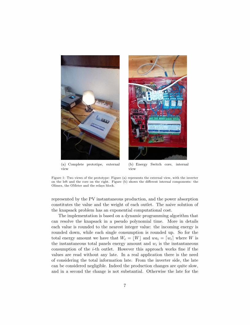
(a) Complete prototipe, externalview
(b) Energy Switch core, internalview
Figure 1: Two views of the prototype: Figure (a) represents the external view, with the inverteron the left and the core on the right. Figure (b) shows the different internal components: theOlimex, the OMeter and the relays block.
represented by the PV instantaneous production, and the power absorptionconstitutes the value and the weight of each outlet. The naive solution ofthe knapsack problem has an exponential computational cost.
The implementation is based on a dynamic programming algorithm thatcan resolve the knapsack in a pseudo polynomial time. More in detailseach value is rounded to the nearest integer value: the incoming energy isrounded down, while each single consumption is rounded up. So for thetotal energy amount we have that Wc = bW c and wai = dwie where W isthe instantaneous total panels energy amount and wi is the instantaneousconsumption of the i-th outlet. However this approach works fine if thevalues are read without any late. In a real application there is the needof considering the total information late. From the inverter side, the latecan be considered negligible. Indeed the production changes are quite slow,and in a second the change is not substantial. Otherwise the late for the
7

monitoring system is quite significant. Indeed let’s call this late Lmonitor.We have that Lmonitor = Lr + Lp + Le where Lr is the late related to themaximum reading frequency of the monitoring system, Lp the propagationdelay of the information from the station to the computing unit and Le isthe elaboration time required by the computing unit. From an analysis ofthese elements, it appears that Lp is very small. Also Le is quite short, sincethe hypothesis of low producing plant. Lr instead is around one second. Asecond is a quite high value in the electrical context, so the effective energysituation at the time of the actuation of the computed configuration can bedifferent and an energy lack can happen. In order to avoid that, the approachproposed is based on the study of the previous behavior of each outlet andon the history of the consumptions. In particular, time is divided in timeslots and for each time slot the mean and the variance of the consumptionsare computed and considered for taking a decision. For choosing the bestapproach both the time slots size and the different logics for the system havebeen tested: so the methodology considered is empirical.
4.1 Fine-Tuning
As previously said, in order to choose the best approach some alterna-tives have been empirically tested and their performances compared. Thismethodology has been considered both for tuning the time slot length andfor detecting the best switching logic.
We took into account the following switching logics: (i) naive, (ii) thresh-old on variance, (iii) threshold on variance/mean ratio, (iv) adaptive onvariance, and (v) adaptive on variance/mean ratio. All of them take intoaccount a safety margin. A safety margin is a percentage of the incomingenergy that is not considered as available for covering hypothetical errorsand energy lacks. On the one hand, the bigger is the safety margin, thelower is the saving; on the other hand, the shorter is the margin, the higheris the error probability. The naive approach has been considered just acomparison term. It does not add any information on the read data, so it isthe most speculative approach and counts many errors. For the remainingapproaches we can detect two groups: the first two approaches are static,while the others are dynamic.
A static approach implements a logic that excludes an outlet from theknapsack computation if the value of the considered metric overcomes afixed threshold. Moreover, the percentage of the safety margin is fixed apriori. On the contrary, a dynamic (or adaptive) approach implements alogic that excludes an outlet from the knapsack computation if the value of
8

the considered metric overcomes a dynamic threshold. The safety margin isdefined dynamically as well: smaller is the value of the considered metric,lower is the percentage of the safety margin.
Starting from the analysis of the Naive approach results, a clear trendhas been detected: the bigger the safety margin is, the lower is the number oftotal errors, but the energy saving slowly decreases. Even the introductionof a little margin causes a big reduction of the errors. However withouta supplementary consideration the system appears not feasible in practicalterms. On the contrary, if the supplementary metric analysis is introduced,the performance are quite good with a small safety margin of the 20% (seeFigure 2). The best results have been obtained with a time slot 30 minuteslength: longer time slots give a less precise description of the consumptionregularity, for shorter time slots can be difficult to catch the events and putthe influence in the right time slot. However testing them in a real contextthe best performances have been reached with the adaptive approach usingthe variance. The saved energy has been the 17% of the total, but thenumber of errors has been just two. This approach is very dynamic since itis not necessary to define the percentage of the safety margin as for the staticapproaches. Hence, the results obtained suggest that the most importantmetric for describing the electric consumption is the variance, computedon 48 daily time slots. If the environment is well known and there are fewchanges in the system settings, the static approach can be adopted. It allowsa greater save but it is weak against the changes. Otherwise the solutionadaptive is more general and does not require particular tuning. Howeverits saving is a little lower, so it is the right tuning if the system setting isvariable or not defined a priori.
1 2 3 4 5 6 7 8 9
10 11 12 13 14 15 16 17 18 19 20 21
0 20 40 60 80
Saved
perc
enta
ge
Safety margin percentage
Saved energy
(a) Energy Saved
0
50
100
150
200
250
300
350
400
450
500
550
600
0 20 40 60 80
N°
err
ors
Safety margin percentage
Errors Occurred
(b) Errors Occurred
Figure 2: Threshold on variance approach simulation results. The number of time slots consideredis 48. The approach tries to minimize the risks when the benefits would be few. The best resultsare obtained with a 20% safety margin.
9

5 Conclusions and Future Works
This work introduces a system that proposes a new approach to the renew-able energy management for small production plants in a domestic environ-ment. We demonstrated that the improvement of the self-consumption canwarranty a saving in terms of energy and money.
Exploiting information technology algorithms and home automation sub-systems, this approach moves the focus from producing more energy to im-proving the self-consumed produced energy changing dynamically the sourceof each active appliance depending to their consumption and to the instan-taneous production. However, a complete exploiting is still infeasible due tothe too quick changes on the production quantity and in the consumptionof the appliances, so some methodologies have been presented, evaluatedand tested through software simulation for studying the best approach. Thetests showed that in the best case the saving obtained is nearly the 20% andthis can be considered a promising starting result.
However, a validation phase for confirming these results is still necessary:for doing it, a controlled ecosystem will be implemented where the prototypeis monitored in order to measure the effective saving and the hypotheticalenergy lacks.
This work represents a first step in the proposed direction based onself-consumption. There are many aspects that can be improved and manypossible solutions can be applied to this aim. For instance, a better indi-viduation of the users’ habits can help in preventing energy lacks and inimproving the performance of the system. Moreover, a more complete in-verter communication facility would allow a more accurate switching: withthe current model, it is easy to measure the instantaneous produced cur-rent, but it is not trivial to compute the maximum potential instantaneouscurrent of the panels. This information would be very useful for computingthe effective maximum load applicable to the PV plant.
References
[1] Elementi di progettazione fotovoltaico - Thermital.
[2] Angel A Bayod-Rujula. Future development of the electricity systemswith distributed generation. Energy, 34(3):377–383, 2009.
[3] Stanley R Bull. Renewable energy today and tomorrow. Proceedings ofthe IEEE, 89(8):1216–1226, 2001.
10

[4] P. Siano C. Cecati, C. Citro. Combined operations of renewable energysystems and responsive demand in a smart grid. IEEE Transaction onSustainable Energy, 2(4):468–476, 2011.
[5] Juan Manuel Carrasco, Leopoldo Garcia Franquelo, Jan T Bialasiewicz,Eduardo Galvan, RC Portillo Guisado, Ma AM Prats, Jose IgnacioLeon, and Narciso Moreno-Alfonso. Power-electronic systems for thegrid integration of renewable energy sources: A survey. Industrial Elec-tronics, IEEE Transactions on, 53(4):1002–1016, 2006.
[6] Mario Caruso. Service Ecologies, Energy Management and Accessibilityin Smart Homes. PhD thesis, Dipartimento di Ingegneria Informat-ica, Automatica e Gestionale A. Ruberti, Sapienza, Universit di Roma,2014.
[7] Manuel Castillo-Cagigal, Estefanıa Caamano-Martın, Eduardo Matal-lanas, Daniel Masa-Bote, A Gutierrez, Felix Monasterio-Huelin, andJavier Jimenez-Leube. Pv self-consumption optimization with storageand active dsm for the residential sector. Solar Energy, 85(9):2338–2348, 2011.
[8] Paolo Crucitti, Vito Latora, and Massimo Marchiori. A topologicalanalysis of the italian electric power grid. Physica A: Statistical Me-chanics and its Applications, 338(1):92–97, 2004.
[9] EPIA the European Photovoltaic Industry Association. Self Consump-tion of PV electricity, July 2013.
[10] Giorgio Gambosi Giorgio Ausiello, Fabrizio D’Amore. Linguaggi, mod-elli, complessit. 2011.
[11] Parikshit Gopalan, Adam Klivans, Raghu Meka, Daniel Stefankovic,Santosh Vempala, and Eric Vigoda. An fptas for# knapsack and relatedcounting problems. In Foundations of Computer Science (FOCS), 2011IEEE 52nd Annual Symposium on, pages 817–826. IEEE, 2011.
[12] Charles Hall, Pradeep Tharakan, John Hallock, Cutler Cleveland, andMichael Jefferson. Hydrocarbons and the evolution of human culture.Nature, 426(6964):318–322, 2003.
[13] Simon Haykin and Neural Network. A comprehensive foundation. Neu-ral Networks, 2(2004), 2004.
11

[14] Wassily Hoeffding. A class of statistics with asymptotically normaldistribution. The Annals of Mathematical Statistics, pages 293–325,1948.
[15] Shri Karve. Three of a kind [ups topologies, iec standard]. IEE Review,46(2):27–31, 2000.
[16] Jon Kleinberg and Eva Tardos. Algorithm design. Pearson EducationIndia, 2006.
[17] Geoffrey Holmes Bernhard Pfahringer Peter Reutemann Ian H. WittenMark Hall, Eibe Frank. The weka data mining software: An update.SIGKDD Explorations, Volume 11(1), 2009.
[18] Manuela Marzotti. Modellistica e analisi dei consumi energetici in am-bito domestico per lidentificazione dellutenza e la rivelazione di anoma-lie. [Master Thesis], 2008.
[19] Thom Metzger and Th Metzger. Blood and volts: Edison, Tesla, andthe electric chair. Autonomedia, 1996.
[20] Andreas Reinhardt, Paul Baumann, Daniel Burgstahler, Matthias Hol-lick, Hristo Chonov, Marc Werner, and Ralf Steinmetz. On the Accu-racy of Appliance Identification Based on Distributed Load MeteringData. In Proceedings of the 2nd IFIP Conference on Sustainable Inter-net and ICT for Sustainability (SustainIT), pages 1–9, 2012.
[21] Wilson Rickerson and Robert C Grace. The debate over fixed priceincentives for renewable electricity in europe and the united states:Fallout and future directions. A White Paper Prepared for The HeinrichBoll Foundation, 2007.
[22] Harold N Scherer and Gregory S Vassell. Transmission of electric powerat ultra-high voltages: current status and future prospects. Proceedingsof the IEEE, 73(8):1252–1278, 1985.
[23] Vijay V Vazirani. Approximation algorithms. springer, 2001.
12