engineering drawings for 10 cfr part 71 package drawings · 2018-08-09 · engineering drawings for...
TRANSCRIPT
UCRL-ID-130438NUREG/CR-5502
Engineering Drawings for 10 CFRPart 71 Package Approvals
Prepared byM. K. Sheaffer, G. R. Thomas, R. K. Dann, E. W. Russell
Prepared forU.S. Nuclear Regulatory Commission

Disclaimer
This document was prepared as an account of work sponsored by an agency of the United StatesGovernment. Neither the United States Government nor the University of California, nor any of theiremployees, makes any warranty, express or implied, or assumes any legal liability or responsibility for theaccuracy, completeness, or usefulness of any information, apparatus, product, or process disclosed, orrepresents that its use would not infringe privately owned rights. Reference herein to any specificcommercial product, process, or service by trade name, trademark, manufacturer, or otherwise, does notnecessarily constitute or imply its endorsement, recommendation, or favoring by the United StatesGovernment or the University of California. The views and opinions of authors expressed herein do notnecessarily state or reflect those of the United States Government or the University of California and shallnot be used for advertising or product endorsement purposes.
This work was supported by the United States Nuclear Regulatory commission under a Memorandum ofUnderstanding with the United States Department of Energy, and performed under the auspices of the U.S.Department of Energy by Lawrence Livermore National Laboratory under Contract W-7405-Eng-48.
UCRL-ID-130438NUREG/CR-5502
Engineering Drawings for 10 CFR Part 71Package Approvals
Manuscript Completed: May 1998Date Published:
Prepared byM. K. Sheaffer, G. R. Thomas, R. K. Dann, E. W. Russell
Lawrence Livermore National Laboratory7000 East AvenueLivermore, CA 94550
Prepared forU.S. Nuclear Regulatory Commission

Engineering Drawings for 10 CFR Part 71 Package Approvals
NUREG/CR-5502 ii

Engineering Drawings for 10 CFR Part 71 Package Approvals
iii NUREG/CR-5502
ABSTRACT
This report provides information for preparing drawings of transportation packages submitted in anapplication for approval under 10 CFR Part 71. It discusses the purpose of these drawings and describesthe recommended format and technical content appropriate for package applications. Examples offrequently used drawing symbols are also provided.

Engineering Drawings for 10 CFR Part 71 Package Approvals
NUREG/CR-5502 iv
Engineering Drawings for 10 CFR Part 71 Package Approvals
v NUREG/CR-5502
CONTENTS
ABSTRACT ......................................................................................................................................................... iii
ACKNOWLEDGMENT ....................................................................................................................................... vi
ACRONYMS....................................................................................................................................................... vii
1. INTRODUCTION............................................................................................................................................. 11.1 Background.............................................................................................................................................. 11.2 Scope ....................................................................................................................................................... 1
2. PURPOSE AND FORMAT OF DRAWINGS.................................................................................................... 12.1 Purpose of Drawings ................................................................................................................................ 12.2 Drawing Format ....................................................................................................................................... 1
3. TECHNICAL CONTENT OF DRAWINGS...................................................................................................... 23.1 General Guidance..................................................................................................................................... 23.2 General Arrangement of Packaging and Contents..................................................................................... 23.3 Package Design Features .......................................................................................................................... 3
3.3.1 General Specifications .................................................................................................................... 33.3.2 Containment Systems ..................................................................................................................... 43.3.3 Closure Devices .............................................................................................................................. 43.3.4 Internal Supporting and Positioning Structures............................................................................... 43.3.5 Neutron Absorbing and Moderating Features Affecting Criticality.................................................. 53.3.6 Neutron Shielding .......................................................................................................................... 53.3.7 Gamma Shielding........................................................................................................................... 53.3.8 Outer Shell or Outer Packaging ...................................................................................................... 63.3.9 Heat-Transfer Features ................................................................................................................... 63.3.10 Impact Limiters/Energy-Absorbing Features ................................................................................. 63.3.11 Lifting and Tie-Down Devices ...................................................................................................... 63.3.12 Personnel Barriers ........................................................................................................................ 63.3.13 Other Design Features .................................................................................................................. 6
4. REFERENCES ................................................................................................................................................. 7
APPENDIX: EXAMPLES OF FREQUENTLY USED DRAWING SYMBOLS..................................................... 9Feature Control Symbols ................................................................................................................................. 9Welding and Nondestructive Evaluation Symbols.......................................................................................... 10Types of Lines............................................................................................................................................... 11Bolt Symbols and Designations ..................................................................................................................... 11Miscellaneous Symbols and Abbreviations .................................................................................................... 11

Engineering Drawings for 10 CFR Part 71 Package Approvals
NUREG/CR-5502 vi
ACKNOWLEDGMENT
This work was funded by the Package Certification Section, Spent Fuel Project Office, Office of NuclearMaterial Safety and Safeguards, U. S. Nuclear Regulatory Commission (NRC). The authors would like tothank Dr. Henry W. Lee and Daniel T. Huang, technical monitors at the NRC, for their overall directionand specific contributions, and Nancy L. Osgood and Ross Chappell for their support and guidance. Thetimely response and attention to detail by Lyssa Campbell during preparation of the manuscripts are greatlyappreciated.

Engineering Drawings for 10 CFR Part 71 Package Approvals
vii NUREG/CR-5502
ACRONYMS
ANSI American National Standards Institute
ASME American Society of Mechanical Engineers
ASTM American Society for Testing and Materials
AWS American Welding Society
CFR Code of Federal Regulations
MIL Military
NRC U.S. Nuclear Regulatory Commission
RG Regulatory Guide

Engineering Drawings for 10 CFR Part 71 Package Approvals
NUREG/CR-5502 viii

1. Introduction
1 NUREG/CR-5502
1. INTRODUCTION
1.1 BackgroundPackages for transporting radioactive material aredesigned and constructed to meet the requirementsof Title 10, Code of Federal Regulations, Part 71(10 CFR Part 71).1 As specified by this regulation,applications for package approval submitted to theU.S. Nuclear Regulatory Commission (NRC) mustinclude a package description and an evaluationthat demonstrates compliance with theseregulatory requirements.
Regulatory Guide 7.9 (RG 7.9) 2, 3 providesguidance on the format and content of theapplication. Chapter 1 of RG 7.9 specifies thatdrawings be included in the application as part ofthe package description. This report supplementsthat guidance and should not be considered asubstitute for either 10 CFR Part 71 or RG 7.9.
1.2 ScopeThis report provides information for preparingdrawings submitted in an application for packageapproval under 10 CFR Part 71. Section 2describes the purpose of the drawings and arecommended format. Section 3 discusses thetechnical content appropriate for drawings inpackage applications. The appendix illustratesfrequently used drawing symbols.
2. PURPOSE AND FORMAT OFDRAWINGS
2.1 Purpose of DrawingsThe primary purpose of drawings submitted in anapplication for package approval under 10 CFRPart 71 is to define the package design. Asspecified by 10 CFR 71.33, an application mustinclude a description of the proposed package insufficient detail to identify the package accuratelyand to provide an adequate basis for its evaluation.Drawings submitted in the application constitutean essential part of that description. Uponapproval by the NRC, the package design definedby these drawings is generally specified as acondition of approval in the certificate ofcompliance.
10 CFR 71.3 requires that transport of radioactivematerial be authorized by a general license or aspecific license issued by the NRC. The generallicense of 10 CFR 71.12, which authorizestransport of radioactive materials in a packageapproved by the NRC, requires that licensees havea copy of the certificate of compliance and complywith other provisions of the general license,including drawings and additional documentsreferenced in the approval of the package.Packages that do not conform to the approveddrawings are not authorized for use since they donot meet the conditions of approval in thecertificate of compliance. Only packagings thatconform to the drawings may be marked with thepackage identification number, as required by 10CFR 71.85(c).
2.2 Drawing FormatDrawings should be included in the appendix toChapter 1 (General Information) of theapplication. A table of contents to the appendixshould identify the drawing and sheet number,revision, and title of all drawings submitted.
Each drawing should include a title block thatidentifies the preparing organization, drawingnumber, sheet number, title, date, and signature orinitials indicating approval of the drawing. Reviseddrawings should identify the revision number,date, and a description of the change in eachrevision. The signature or initials of the individualapproving the revision should also be included.
Drawings should be legible and should conform tothe page size, quality of paper and inks, and otherphysical specifications recommended by RG 7.9.The preferred page size is 8-1/2 x 11 inches, andthe maximum size should be 11 x 17 inches.Drawings should be printed on oneside only.
All symbols and other notation should be inaccordance with established standards or otherwisedefined on the drawings. The DrawingRequirements Manual4 describes common drawingpractices and provides an extensive listing ofstandards endorsed by various government andprofessional organizations, including ASMEY14.5M5 and ANSI/AWS 2.4.6
4. References
NUREG/CR-5502 2
In addition, drawing practices are usuallyprescribed by quality assurance or otherprocedures of the preparing organization. Theappendix to this report illustrates symbolsfrequently used on package drawings.
Drawings submitted under the provisions of10 CFR 2.7907 should be marked as proprietary,and the proprietary information should be clearlyidentified.
3. TECHNICAL CONTENT OFDRAWINGS
3.1 General GuidanceBecause of the large number of different packagetypes and the numerous variations in designfeatures, no document can completely addressevery detail that should be included on thedrawings. Based on the purpose of the drawingsdiscussed in Section 2.1, the following generalguidance should be considered for each proposedpackage design:
· The drawings should specify those details ofthe package design which affect its evaluationunder 10 CFR Part 71.
· Conformance of the package to the designspecified by the drawings will be a conditionof approval for use of the package.
The technical content appropriate for drawingssubmitted in a package application may differsubstantially from that of other drawings routinelyprepared for design and fabrication. Applicationdrawings should be more detailed than packageschematics illustrated in the main body of theapplication. Detailed fabrication (shop) drawings,however, may provide excessive detail that is notappropriate as a condition of approval.
Drawings submitted in an application shouldconsist of a general arrangement drawing, withadditional drawings of detailed design features, asnecessary. Notes, material parts lists,specifications, and codes or standards forfabrication should also be included as part of thedrawings, as discussed in the following sections ofthis report.
3.2 General Arrangement ofPackaging and ContentsThe general arrangement drawing should depictthe package configuration as presented forshipment in both side and plan views. Alternateconfigurations, if applicable, should also beshown. The general arrangement drawing shouldinclude:
· Packaging and content dimensions
· Design features which affect the packageevaluation
· Packaging markings
· Maximum allowable weight of package
· Maximum allowable weight of contents andsecondary packaging.
The dimensions shown on the general arrangementdrawing should specify the overall size of thepackaging and the location and configuration ofthe contents. All dimensions indicated on drawingsshould include tolerances that are consistent withthe package evaluation. Tolerances may beaddressed by a drawing note that defines a generaltolerance applicable to many features. If a designfeature needs a more (or less) restrictive tolerancethan indicated by the note, the appropriatetolerance should be specified explicitly in thedimensioning of that feature. In the discussionbelow, the term dimension should always beconsidered to mean dimension with appropriatetolerance.
Guidance on specifying design features isdiscussed in Section 3.3. To the extent practical,this information should be shown on the generalarrangement drawing. Other design features, oradditional detail for these features, may beincluded on separate drawings or sheets, whichshould be referenced as appropriate in the generalarrangement drawing. Drawings should include alldesign features affecting the package evaluation.
The general arrangement drawing should show thelocation and size of durable markings applied tothe packaging after verification that it has beenfabricated in accordance with the approved design.As specified by 10 CFR 71.85(c), these markings

4. References
3 NUREG/CR-5502
must include the package model number, serialnumber, gross weight, and package identificationnumber. Additional marking and labelingrequirements are specified in 49 CFR Part 172,8Subparts D and E.
The maximum allowable weights of the packageand contents should be indicated on the generalarrangement drawing. The maximum weight of thepackage should include the packaging and itscontents. The maximum weight of the contentsshould include the radioactive contents, secondarycontainers, wrapping, shoring, and any othermaterial transported in the package that is notdefined as part of the packaging. All weightsshould be consistent with those used in theevaluation.
3.3 Package Design FeaturesThe drawings should specify design features insufficient detail to assure that a package whichconforms to the drawing specifications will beconsistent with the design evaluated in theapplication. To the extent practical, designfeatures should be depicted on the generalarrangement drawing, with additional drawings orsheets provided as necessary. Design featuresaffecting the package evaluation include:
· Containment systems
· Closure devices
· Internal supporting or positioning structures
· Neutron absorbing and moderating featuresaffecting criticality
· Neutron shielding
· Gamma shielding
· Outer shell or outer packaging
· Heat-transfer features
· Impact limiters/Energy-absorbing features
· Lifting and tie-down devices
· Personnel barriers
· Other design features.
General specifications that should be included ondrawings are described in Section 3.3.1. Moredetailed guidance for each of the above designfeatures is presented in Sections 3.3.2 to 3.3.13.
3.3.1 General Specifications
The following information for each design featureshould be shown on the drawings, as appropriate:
· Identification of the design feature and itscomponents
· Materials of construction, includingappropriate material specifications
· Codes, standards, or other similarspecification documents for fabrication,examination, assembly, and testing
· Location with respect to other packagefeatures
· Dimensions (with appropriate tolerances)
· Operational specifications.
Drawings should specify the name, materials ofconstruction, and quantity required for each designfeature, component, or part, as applicable. Thisinformation may be provided by a parts list orother appropriate designation. Materials ofconstruction should include a code or standard(e.g., ASME, ASTM, MIL), commercialequivalent, or other appropriate specification forthe material. If this designation does notsufficiently define all material properties affectingthe package evaluation, additional specificationsshould be provided by a drawing note or similarmeans. Examples in which additionalspecifications may be necessary are described inSections 3.3.5 and 3.3.6 for neutron absorbing andmoderating materials.
The drawings should indicate codes, standards, orother similar specification documents forfabrication, examination, assembly, and testing(e.g., ANSI, ASME, MIL, AWS). Thesespecifications should be consistent with those usedfor the package design and may be included indrawing notes, as appropriate. Specialrequirements (e.g., surface finishes), should alsobe depicted, if applicable. Welding specificationsshould include location, type of weld, dimensions,

4. References
NUREG/CR-5502 4
face and root contour, process specifications,examination method, and other applicableinformation consistent with the packageevaluation. Welding details should be depicted byan appropriate welding symbol, with additionalinformation included in drawing notes, asnecessary. Further guidance on fabrication andwelding criteria is provided in NUREG/CR-38549
and NUREG/CR-3019,10 respectively. Examplesof welding symbols are shown in the appendix.
Design features should include dimensions ofcomponents and dimensions that identify theirlocation relative to other package features.Dimensions should be consistent with those in theparts list and those used in the package evaluation.As discussed above, dimensions should includeappropriate tolerances.
Operational specifications such as bolt torque,pressure-relief settings, or similar informationshould also be shown on the drawings, asapplicable.
3.3.2 Containment Systems
The drawings should depict the complete boundaryof the containment system. This may include thecontainment vessel, welds, drain or fill ports, ventports, test ports, valves, seals, lids, cover plates,and other closure devices. If multiple seals areused for a single closure, the seal defined as thecontainment-system seal should be clearlyidentified. The drawings should include, asappropriate:
· Location of components
· Materials of construction, overall dimensions,wall thickness, and dimensions of thetransition from the vessel shell to the closuredevice
· Welds and weld specifications
· Location and dimensions of penetrations
· Requirements for straightness, roundness,flatness, or surface finish, as applicable
· Closure devices, as discussed in Section 3.3.3.
3.3.3 Closure Devices
The drawings should show all closure devices forthe containment system, outer packaging, andother closed volumes (e.g., expansion tanks).Closure devices may include flanges, seals, coverplates, lids, bolts, closure rings, welds, valves, andpressure-relief devices. The drawings shouldinclude, as appropriate:
· Location of components
· Dimensions and materials of construction offlanges, seals, lids, cover plates, and closurerings
· Containment seal specifications
· Dimensions of seal grooves
· Surface-finish specifications for flanges andgrooves
· Welds and weld specifications
· Number, size, materials of construction, andthread specifications for bolts or otherfastening devices
· Closure bolt torques
· Specifications for valves and pressure-reliefdevices
· Dimensions of gaps or clearances to reduce oreliminate differential thermal expansion ormechanical loading on other components
· Requirements for straightness, roundness,flatness, or surface finish
· Lifting devices of the closure component, asdiscussed in Section 3.3.11
· Tamper-indicating device.
3.3.4 Internal Supporting and PositioningStructures
The drawings should show the design features thatsupport or position the contents. These structuresmay be fastened to other packaging components orto the contents. Internal structures may includestrongbacks, shock absorbers, baskets, gammashields, spacers, shims, pellet trays, foam,insulation, or similar features. The outer shell of
4. References
5 NUREG/CR-5502
the packaging and impact limiters are discussedseparately in Sections 3.3.8 and 3.3.10,respectively. The drawings should include, asappropriate:
· Location, dimensions, and materials ofconstruction
· Density of foam, insulation, or similarmaterials
· Dimensions of gaps or clearances to reduce oreliminate loading on other components
· Method of attachment to contents or otherpackaging components
· Welds and weld specifications
· Form of shims and spacers (e.g., woodenblocks, metal sheets, rubber pads).
3.3.5 Neutron Absorbing and ModeratingFeatures Affecting Criticality
The drawings should identify neutron absorbingand moderating features that affect the criticalityevaluation of the package. The drawings shouldinclude, as appropriate:
· Location, dimensions, materials ofconstruction, and chemical composition ofneutron absorbers and moderators
· Minimum density of neutron absorbingmaterials and moderators
· Minimum isotopic composition of neutronabsorbing materials (e.g., wt% 10B)
· Maximum quantity and density of moderatingmaterials affecting criticality, gas generation,or other package evaluation (e.g., plastic bags,moisture content, and spacers)
· Method of attachment to contents or structuralcomponents
· Location and dimensions of voids or otherfloodable volumes (including those in whichpreferential flooding is possible) that couldaffect neutron absorption or moderation
· Expansion voids, piping, valves, seals, andassociated mounting details for expansion-tank
systems that provide neutron absorption ormoderation.
3.3.6 Neutron Shielding
Although some design features important forshielding are similar to those for criticality, severalimportant differences exist. The drawings shouldshow, as appropriate:
· Location, dimensions, materials ofconstruction, and chemical composition ofneutron absorbers and moderators (e.g.,NS4-FR, polyethylene, water)
· Physical form (solid or liquid)
· Minimum density of neutron absorbing andmoderating nuclides (e.g., B and H)
· Minimum isotopic composition of neutronabsorbing materials (e.g., wt% 10B)
· Details of penetrations through the shield (e.g.,heat transfer fins, trunnions)
· Applicable gaps, voids, clearances, joiningmethods, or other details affecting streamingpaths
· Special treatments to liquid shields (e.g.,addition of antifreeze)
· Special features (e.g., expansion tanks,pressure relief valves).
3.3.7 Gamma Shielding
The drawings should include design features thatare used to reduce the external gamma radiation.These may include lead or depleted uranium, aswell as other components that also providestructural support or thermal protection. Thedrawings should include, as appropriate:
· Location, dimensions, materials ofconstruction, and maximum weight
· Details of penetrations through the shield
· Applicable gaps, voids, clearances, joiningmethods, or other details affecting streamingpaths
· Method of attachment to other packagingstructural components.

4. References
NUREG/CR-5502 6
3.3.8 Outer Shell or Outer Packaging
The drawings should include, as appropriate:
· Location, dimensions, and materials ofconstruction
· Specifications for drum chimes and rollinghoops
· Welds and weld specifications
· Location and dimensions of penetrations
· Closure devices, as discussed in Section 3.3.3,including features to prevent water inleakageunder normal conditions of transport
· Heat transfer features, as discussed inSection 3.3.9
· Method of impact-limiter attachment, asdiscussed in Section 3.3.10
· Lifting and tie-down devices, as discussed inSection 3.3.11
· Applicable surface-finish specifications
· Coatings or paints (may be designated asoptional if they serve no safety function).
3.3.9 Heat-Transfer Features
The drawings should depict all features that affectthe transfer of heat within the package andbetween the package and the environment. Thesemay include gaps and surface contacts, fill-gas,thermal shields, fins, surface finishes, as well ascomponents described in other design features. Thedrawings should include, as appropriate:
· Dimensions, location, and other appropriatespecifications for gaps and surface contactsbetween packaging components or betweenpackaging components and the contents
· Fill-gas material and pressure specifications
· Location, dimensions, and materials ofconstruction of fins or similar features, andtheir method of attachment
· Location, dimensions, and materials ofconstruction of thermal shields, and theirmethod of attachment
· Surface-finish specifications.
3.3.10 Impact Limiters/Energy-AbsorbingFeatures
The drawings should include, as appropriate:
· Location, dimensions, and materials ofconstruction, including outer and inner shells,energy absorbing materials, and othercomponents
· Method of attachment, including location,number, size, materials of construction andspecifications for bolts and lugs, or similardevices.
3.3.11 Lifting and Tie-Down Devices
Lifting and tie-down devices may includetrunnions, lugs, threaded sockets, eyebolts, skids,and similar devices. The drawings should include,as appropriate:
· Location, dimensions, materials ofconstruction, and interface with otherpackaging components
· Interface specifications with lifting device orvehicle, as evaluated in the application.
3.3.12 Personnel Barriers
Personnel barriers can be used to meet theexternal radiation limits of 10 CFR 71.47(a) or(b), or the temperature limits of 10 CFR 71.43(g).The drawings should indicate, as appropriate:
· Location, dimensions, and materials ofconstruction
· Method of attachment to packaging.
3.3.13 Other Design Features
The drawings should show any other designfeatures relevant to the package evaluation.Features that are not important to packageperformance may be illustrated for information.The drawings should clearly identify optionalfeatures or arrangements.

4. References
7 NUREG/CR-5502
4. REFERENCES1. U.S. Code of Federal Regulations, “Packaging
and Transportation of Radioactive Materials,”Part 71, Title 10, “Energy.”
2. U.S. Nuclear Regulatory Commission,“Standard Format and Content of Part 71Applications for Approval of Packaging forRadioactive Material,” Task FC 416-4,Proposed Revision 2 to Regulatory Guide 7.9.
3. U.S. Nuclear Regulatory Commission,“Standard Format and Content of Part 71Applications for Approval of Packaging ofType B, Large Quantity, and FissileRadioactive Material,” Regulatory Guide 7.9.
4. J. J. Lieblich and G. Whitmire, DrawingRequirements Manual, Ninth Edition, GlobalEngineering Documents, Englewood,Colorado, 1995.
5. American Society of Mechanical Engineers,ASME Y14.5M-1994, “Dimensioning andTolerancing,” New York.
6. American National Standards Institute/American Welding Society, ANSI/AWS 2.4-1997, “Symbols for Welding, Brazing, andNondestructive Examination,” AWS, Miami,Florida.
7. U.S. Code of Federal Regulations, “Rules ofPractice for Domestic Licensing Proceedingsand Issuance of Orders,” Part 2, Title 10,“Energy.”
8. U.S. Code of Federal Regulations,“Hazardous Materials Table, SpecialProvisions, Hazardous MaterialCommunications, Emergency ResponseInformation, and Training Requirements,”Part 172, Title 49, “Transportation.”
9. U.S. Nuclear Regulatory Commission,“Fabrication Criteria for ShippingContainers,” NUREG/CR-3854, March 1985.
10. U.S. Nuclear Regulatory Commission,“Recommended Welding Criteria for Use inthe Fabrication of Shipping Containers forRadioactive Materials,” NUREG/CR-3019,March 1984.

4. References
NUREG/CR-5502 8
Appendix: Examples of Frequently Used Drawing Symbols
9 NUREG/CR-5502
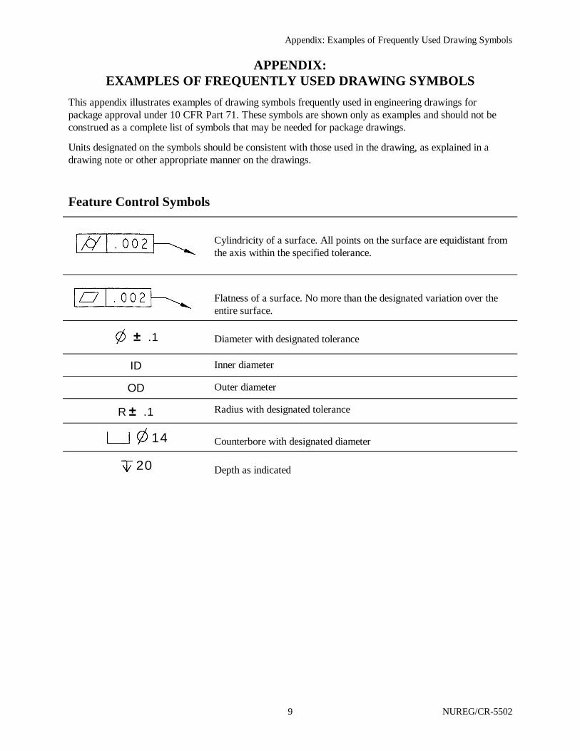
APPENDIX:EXAMPLES OF FREQUENTLY USED DRAWING SYMBOLS
This appendix illustrates examples of drawing symbols frequently used in engineering drawings forpackage approval under 10 CFR Part 71. These symbols are shown only as examples and should not beconstrued as a complete list of symbols that may be needed for package drawings.
Units designated on the symbols should be consistent with those used in the drawing, as explained in adrawing note or other appropriate manner on the drawings.
Feature Control Symbols
Cylindricity of a surface. All points on the surface are equidistant fromthe axis within the specified tolerance.
Flatness of a surface. No more than the designated variation over theentire surface.
± .1 Diameter with designated tolerance
ID Inner diameter
OD Outer diameter
R ± .1 Radius with designated tolerance
14 Counterbore with designated diameter
20 Depth as indicated
Surface texture or finish, with a roughness average as indicated.
5.30 ± .05Linear tolerance (minimum length = 5.25, maximum length = 5.35)
1.67 1.55 DIA Maximum/Minimum diameter
.05 A Tolerance for true position of diameter with respect to datum A. Forexample, diameter of O-ring groove is within 0.05 of inner cylinderdiameter (datum A).
Appendix: Examples of Frequently Used Drawing Symbols
NUREG/CR-5502 10
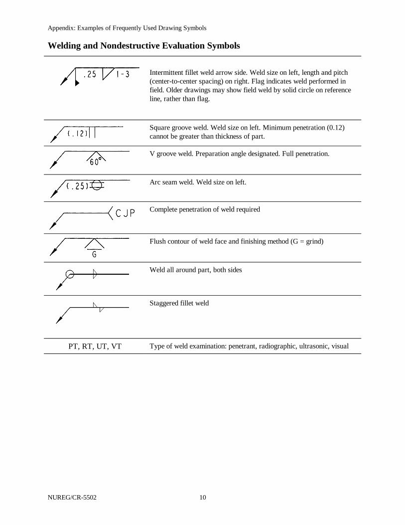
Welding and Nondestructive Evaluation Symbols
Intermittent fillet weld arrow side. Weld size on left, length and pitch(center-to-center spacing) on right. Flag indicates weld performed infield. Older drawings may show field weld by solid circle on referenceline, rather than flag.
Square groove weld. Weld size on left. Minimum penetration (0.12)cannot be greater than thickness of part.
V groove weld. Preparation angle designated. Full penetration.
Arc seam weld. Weld size on left.
Complete penetration of weld required
Flush contour of weld face and finishing method (G = grind)
Weld all around part, both sides
Staggered fillet weld
PT, RT, UT, VT Type of weld examination: penetrant, radiographic, ultrasonic, visual
Appendix: Examples of Frequently Used Drawing Symbols
11 NUREG/CR-5502
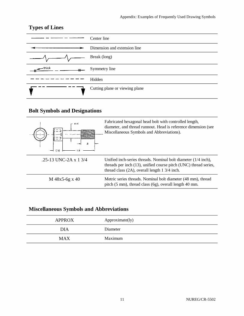
Types of Lines
Center line
Dimension and extension line
Break (long)
Symmetry line
Hidden
Cutting plane or viewing plane
Bolt Symbols and Designations
Fabricated hexagonal head bolt with controlled length,diameter, and thread runnout. Head is reference dimension (seeMiscellaneous Symbols and Abbreviations).
.25-13 UNC-2A x 1 3/4 Unified inch-series threads. Nominal bolt diameter (1/4 inch),threads per inch (13), unified course pitch (UNC) thread series,thread class (2A), overall length 1 3/4 inch.
M 48x5-6g x 40 Metric series threads. Nominal bolt diameter (48 mm), threadpitch (5 mm), thread class (6g), overall length 40 mm.
Miscellaneous Symbols and Abbreviations
APPROX Approximate(ly)
DIA Diameter
MAX Maximum

Appendix: Examples of Frequently Used Drawing Symbols
NUREG/CR-5502 12
MIN Minimum
NOM Nominal
REF or ( ) Reference. A dimension that is an accumulation of otherdimensions. Reference callouts state either the mean or nominaldimension; the tolerance may be stated when necessary. Areference dimension is not used for manufacturing or inspectionpurposes. May also be used for a dimension that is specifiedelsewhere in the drawing. Reference dimensions may also beindicated by enclosing the dimension value in parentheses.
TYP Typical. Designation applies to other identical features. Shouldbe avoided. Use number of places instead (see below).
8X Number of places (8) for identical features.

Appendix: Examples of Frequently Used Drawing Symbols
13 NUREG/CR-5502