engineering standard for piping material selection
TRANSCRIPT

IPS-E-PI-221(1)
This Standard is the property of Iranian Ministry of Petroleum. All rights are reserved to the owner. Neither whole nor any part of this document may be disclosed to any third party, reproduced, stored in any retrieval system or transmitted in any form or by any means without the prior written consent of the Iranian Ministry of Petroleum.
ENGINEERING STANDARD
FOR
PIPING MATERIAL SELECTION
(ON PLOT PIPING)
PART ONE
GENERAL
FIRST EDITION APRIL 2012
April 2012
IPS-E-PI-221(1)
1
FOREWORD
The Iranian Petroleum Standards (IPS) reflect the views of the Iranian Ministry of Petroleum and are intended for use in the oil and gas production facilities, oil refineries, chemical and petrochemical plants, gas handling and processing installations and other such facilities.
IPS are based on internationally acceptable standards and include selections from the items stipulated in the referenced standards. They are also supplemented by additional requirements and/or modifications based on the experience acquired by the Iranian Petroleum Industry and the local market availability. The options which are not specified in the text of the standards are itemized in data sheet/s, so that, the user can select his appropriate preferences therein.
The IPS standards are therefore expected to be sufficiently flexible so that the users can adapt these standards to their requirements. However, they may not cover every requirement of each project. For such cases, an addendum to IPS Standard shall be prepared by the user which elaborates the particular requirements of the user. This addendum together with the relevant IPS shall form the job specification for the specific project or work.
The IPS is reviewed and up-dated approximately every five years. Each standards are subject to amendment or withdrawal, if required, thus the latest edition of IPS shall be applicable
The users of IPS are therefore requested to send their views and comments, including any addendum prepared for particular cases to the following address. These comments and recommendations will be reviewed by the relevant technical committee and in case of approval will be incorporated in the next revision of the standard.
Standards and Research department
No.17, Street14, North kheradmand
Karimkhan Avenue, Tehran, Iran .
Postal Code- 1585886851
Tel: 88810459-60 & 66153055
Fax: 88810462
Email: Standards@ nioc.ir
April 2012
IPS-E-PI-221(1)
2
GENERAL DEFINITIONS
Throughout this Standard the following definitions shall apply.
COMPANY :
Refers to one of the related and/or affiliated companies of the Iranian Ministry of Petroleum such as National Iranian Oil Company, National Iranian Gas Company, National Petrochemical Company and National Iranian Oil Refinery And Distribution Company.
PURCHASER :
Means the “Company" where this standard is a part of direct purchaser order by the “Company”, and the “Contractor” where this Standard is a part of contract document.
VENDOR AND SUPPLIER:
Refers to firm or person who will supply and/or fabricate the equipment or material.
CONTRACTOR:
Refers to the persons, firm or company whose tender has been accepted by the company.
EXECUTOR :
Executor is the party which carries out all or part of construction and/or commissioning for the project.
INSPECTOR :
The Inspector referred to in this Standard is a person/persons or a body appointed in writing by the company for the inspection of fabrication and installation work.
SHALL:
Is used where a provision is mandatory.
SHOULD:
Is used where a provision is advisory only.
WILL:
Is normally used in connection with the action by the “Company” rather than by a contractor, supplier or vendor.
MAY:
Is used where a provision is completely discretionary.
April 2012
IPS-E-PI-221(1)
3
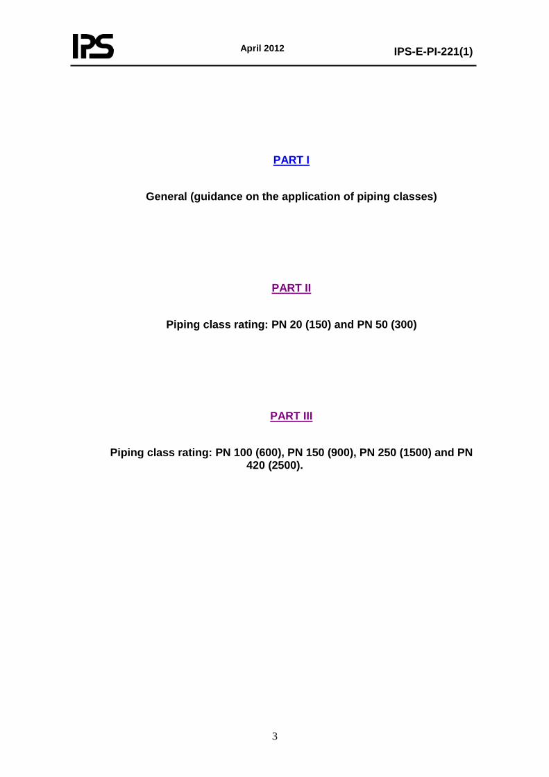
PART I
General (guidance on the application of piping classes)
PART II
Piping class rating: PN 20 (150) and PN 50 (300)
PART III
Piping class rating: PN 100 (600), PN 150 (900), PN 250 (1500) and PN 420 (2500).
April 2012
IPS-E-PI-221(1)
4
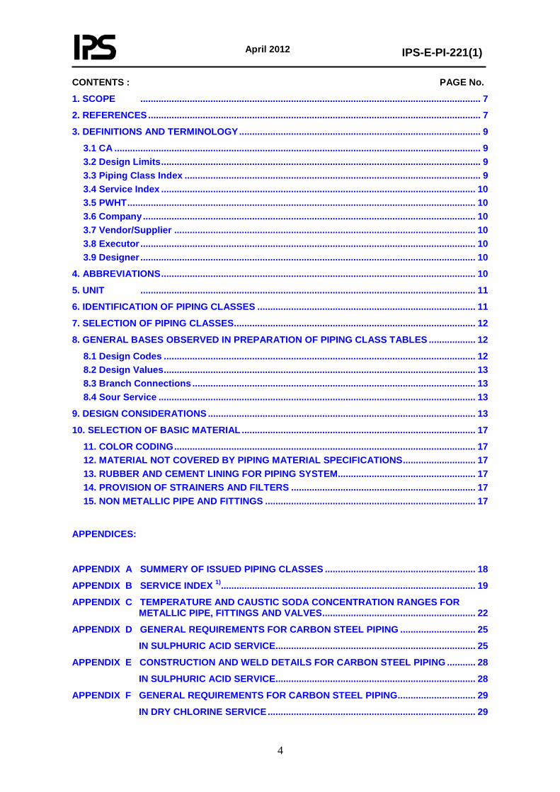
CONTENTS : PAGE No.
1. SCOPE ................................................................................................................................... 7
2. REFERENCES ................................................................................................................................ 7
3. DEFINITIONS AND TERMINOLOGY ............................................................................................. 9
3.1 CA ............................................................................................................................................. 9 3.2 Design Limits ........................................................................................................................... 9 3.3 Piping Class Index .................................................................................................................. 9 3.4 Service Index ......................................................................................................................... 10 3.5 PWHT ...................................................................................................................................... 10 3.6 Company ................................................................................................................................ 10 3.7 Vendor/Supplier .................................................................................................................... 10 3.8 Executor ................................................................................................................................. 10 3.9 Designer ................................................................................................................................. 10
4. ABBREVIATIONS ......................................................................................................................... 10
5. UNIT ................................................................................................................................. 11
6. IDENTIFICATION OF PIPING CLASSES .................................................................................... 11
7. SELECTION OF PIPING CLASSES ............................................................................................. 12
8. GENERAL BASES OBSERVED IN PREPARATION OF PIPING CLASS TABLES .................. 12
8.1 Design Codes ........................................................................................................................ 12 8.2 Design Values ........................................................................................................................ 13 8.3 Branch Connections ............................................................................................................. 13 8.4 Sour Service .......................................................................................................................... 13
9. DESIGN CONSIDERATIONS ....................................................................................................... 13
10. SELECTION OF BASIC MATERIAL .......................................................................................... 17
11. COLOR CODING .................................................................................................................... 17 12. MATERIAL NOT COVERED BY PIPING MATERIAL SPECIFICATIONS ............................ 17 13. RUBBER AND CEMENT LINING FOR PIPING SYSTEM ..................................................... 17 14. PROVISION OF STRAINERS AND FILTERS ....................................................................... 17 15. NON METALLIC PIPE AND FITTINGS ................................................................................. 17
APPENDICES:
APPENDIX A SUMMERY OF ISSUED PIPING CLASSES .......................................................... 18
APPENDIX B SERVICE INDEX 1).................................................................................................. 19
APPENDIX C TEMPERATURE AND CAUSTIC SODA CONCENTRATION RANGES FOR METALLIC PIPE, FITTINGS AND VALVES ........................................................... 22
APPENDIX D GENERAL REQUIREMENTS FOR CARBON STEEL PIPING ............................. 25
IN SULPHURIC ACID SERVICE............................................................................. 25
APPENDIX E CONSTRUCTION AND WELD DETAILS FOR CARBON STEEL PIPING ........... 28
IN SULPHURIC ACID SERVICE............................................................................. 28
APPENDIX F GENERAL REQUIREMENTS FOR CARBON STEEL PIPING .............................. 29
IN DRY CHLORINE SERVICE ................................................................................ 29

April 2012
IPS-E-PI-221(1)
5
APPENDIX G GENERAL REQUIREMENTS FOR PIPING IN HYDROGEN FLUORIDE (HF) SERVICE ................................................................................................................. 32
APPENDIX H GENERAL REQUIREMENTS FOR RUBBER LININGS
FOR PROCESS EQUIPMENT AND PIPING .......................................................... 34
APPENDIX I GENERAL REQUIREMENTS FOR CEMENT LINING OF NEW PIPELINES ......... 48
APPENDIX J REQUIREMENTS FOR GLASS-FIBRE REINFORCED EPOXY
PIPES AND FITTINGS ............................................................................................ 73
APPENDIX K PIPE COMPONENTS - NOMINAL SIZE ................................................................. 85
APPENDIX L PIPE FLANGES PRESSURE TEMPERATURE RATING ....................................... 86
APPENDIX M EXTENDED SERVICE LIMITS FOR PIPING CLASSES AT ELEVATED TEMPERATURE...................................................................................................... 87
APPENDIX N VENT, DRAIN, AND PRESSURE INSTRUMENTS CONNECTIONS
ASSEMBLIES.......................................................................................................... 88

April 2012
IPS-E-PI-221(1)
6
ENGINEERING STANDARD
FOR
PIPING MATERIAL SELECTION
(ON PLOT PIPING)
PART ONE GENERAL
April 2012
IPS-E-PI-221(1)
7
1. SCOPE
This Standard contains piping classes primarily developed for petroleum refineries, gas and petrochemical plants installed onshore. It is also intended for use in onshore exploration and production facilities as well as booster stations as far as applicable. Facilities covered by this Standard are all within the property limits as defined in ASME B31.3.
Note:
This is a revised version of this standard, which is issued as revision (1)-2012. Revision (0)-2000 of the said standard specification is withdrawn.
2. REFERENCES
Throughout this Standard the following dated and undated standards/codes are referred to. These referenced documents shall, to the extent specified herein, form a part of this standard. For dated references, the edition cited applies. The applicability of changes in dated references that occur after the cited date shall be mutually agreed upon by the Company and the Vendor. For undated references, the latest edition of the referenced documents (including any supplements and amendments) applies.
ASME (AMERICAN SOCIETY OF MECHANICAL ENGINEERS)
B1.1 “Unified Inch Screw Threads (UN and UNR Thread Form)”
B1.20.1 “Pipe Threads, General Purpose (Inch)”
B16.10 “Face to Face and End to End Dimensions of Valves”
B16.11 “Forged Steel Fittings, Socket Welding and Threaded”
B16.20 “Metallic Gaskets for Pipe Flanges-Ring Joint, Spiral-Wound, and Jacketed”
B16.21 “Nonmetallic Flat Gaskets for Pipe Flanges”
B16.25 “Buttwelding Ends”
B16.28 “Wrought Steel Buttwelding Short Radius Elbows and Returns”
B16.3 “Malleable Iron Threaded Fittings, Class 150 and 300”
B16.34 “Valves-Flanged, Threaded, and Welding End”
B16.36 “Orifice Flanges”
B16.42 “Ductile Iron Pipe Flanges and Flanged Fittings (Class 150 and 300)”
B16.47 “Large Diameter Steel Flanges NPS 26 through NPS 60”
B16.9 “Factory-Made Wrought Steel Buttwelding Fitting”
B18.2.2 “Square and Hex Nuts (Inch Series)”
B46.1 “Surface Texture (Surface Roughness, Waviness and Lay)”
PVBC section I “Rules for Construction of Power Boilers”
B-31.1- 2004 “Power Piping”
B-31.3- 2010 “Process Piping”
B-36.10M- 2004 “Welded and Seamless Wrought Steel Pipe”
B-36.19M “Stainless Steel Pipe”
B-16.5- 2003 “Pipe Flanges and Flanged Fittings”
April 2012
IPS-E-PI-221(1)
8
Section VIII Division I Appendix 2
API (AMERICAN PETROLEUM INSTITUTE)
API-598 “Valve Inspection and Testing”
API-599 “Metal Plug Valves-Flanged and Welding Ends”
API-600 “Steel Gate Valves, Flanged and Buttwelding Ends”
API-601 “Metallic Gasket for Raised-Face, Pipe Flanges and Flanged Connections (Double Jacketed Corrugated and Spiral-wound)”
API-602 “Compact Steel Gate Valves-Flanged, Threaded, Welding and Extended-Body Ends”
API-609 “Butterfly valves, Lug-Type and Wafer-Type”
API-6D “Pipeline Valves (Gate, Plug, Ball and Check-Valves)”
API-941 “Steels for Hydrogen Service at Elevated Temperature and Pressure in Petroleum Refineries and Petrochemical Plants.”
RP-521 “Guide for Pressure-Relieving and Depressuring Systems”
BSI (BRITISH STANDARD INSTITUTION)
BS-5146 “Specification for Inspection and Test of Steel Valves for the petroleum, petrochemical and allied inspection”
BS-5352 “Steel Wedge Gate, Globe and Check Valves”
BS-5351 “Steel Ball Valves”
BS 3274- 1960 “Tubular Heat Exchangers for General Purposes”
BS 3293- 1960 “Specification for Carbon Steel Pipe Flanges (over 24" nominal size) for the Petroleum Industry”
BS 4485- 1988 “Water Cooling Towers”
BS 6129-1- 1981 “Selection and Application of Bellows Expansion Joints”
IPS (IRANIAN PETROLEUM STANDARDS)
IPS-E-GN-100 “Engineering Standard for Units”
IPS-M-GN-130 “Material and Equipment Standard for Metric Type Fasteners (Screw Bolts, Screw Threads, Nuts, Washers)’
IPS-C-ME-130 “Construction Standard for LPG pressure Storage Spheres”
IPS-C-PI-350 “Construction Standard for Plant Piping Systems Pressure Testing”
IPS-E-PI-200 “Engineering Standard for Flexibility Analysis”
IPS-E-PI-240 “Engineering Standard for Plant Piping Systems”
IPS-G-PI-230 “General Standard for Strainers and Filters”
IPS-G-PI-280 “General Standard for Pipe Supports”
IPS-M-PI-110 “Material and Equipment Standard for Valves”
IPS-M-PI-150 “Material and Equipment Standard for Flanges & Fittings”
IPS-E-SF-220 “Engineering Standard for Fire Water Distribution & Storage Facilities”
IPS-G-SF-460 “General Standard for First aids and Sanitation”
April 2012
IPS-E-PI-221(1)
9
IPS-C-TP-102 “Construction Standard for Painting”
IPS-E-TP-100 “Engineering Standard for Paints”
IPS-E-TP-270 “Engineering Standard for Coatings”
IPS-E-TP-700 “Engineering Standard for Thermal Insulations”
IPS-E-TP-740 “Engineering Standard for Corrosion Consideration in Material Selection”
IPS-D-PI-119 “Pressure Blind Detail”
IPS-D-PI-121 “Hydrostatic Test Blinds Thickness Allowable Test Pressure”
IPS-D-PI-129 “Miter Bends”
IPS-D-PI-148 “Ring & Blind for DN 650 (26") DN 1500 (60") R.F. Flange”
NACE (NATIONAL ASSOCIATION OF CORROSION ENGINEERS)
Paper No. 67
MR-01-75 “Standard Material Requirement Sulfide Stress Cracking Resistant Metallic Material for Oil Field Equipment”
MR-01-03 “Materials Resistant to Sulfide Stress Cracking in Corrosive Petroleum Refining Environments.”
NFPA (NATIONAL FIRE PROTECTION ASSOCIATION)
30- 2003 “Flammable and Combustible Liquids Code”
MSS (MANUFACTURERS STANDARDIZATION SOCIETY)
MSS-SP-6- 2001 “Standard Finishes for Contact Faces of Pipe Flanges and Connecting-End Flanges of Valves and Fittings”
MSS-SP-58- 1993 “Pipe Hangers and Supports-Materials, Design and Manufacture”
MSS-SP-69- 2002 “Pipe Hangers and Supports-Selection and Application”
3. DEFINITIONS AND TERMINOLOGY
3.1 CA
Corrosion allowance.
3.2 Design Limits
Pressure/temperature limits given in piping classes.
3.3 Piping Class Index
A term which identifies the main characteristics of all piping classes. (e.g. materials for pipe, valve trim and gaskets).
April 2012
IPS-E-PI-221(1)
10
3.4 Service Index
A term which identifies which piping class to select for the service concerned and mentioned in the list (without prefix related to ASME rating).
3.5 PWHT
Indicates post weld heat treatment.
3.6 Company Refers to one of the related and/or affiliated companies of the Iranian Ministry of Petroleum such as National Iranian Oil Company, National Iranian Gas Company, National Petrochemical Company etc.
3.7 Vendor/Supplier
Refers to firm or person who will supply and/or fabricate the equipment or material.
3.8 Executor
The party which carries out all, or part of the construction, installation and commissioning aspect for the projects.
3.9 Designer
The person or party which is responsible to the Company for engineering/design of the plants.
Note:
Any specific application of the terms and responsibilities for the parties defined above, are a matter for the conditions of contract on a project.
4. ABBREVIATIONS
BTV Butterfly valve
DRJ Dresser coupling
EH Exhaust head
FG Sight glass
FRV Freeze proof valve (Kelly type)
HC Hose connection
IF Insulation bolt & gasket
INJ Injection nozzle
LKC Lock & locking chain
MDMT Minimum Design Metal Temperature
ME Duplex type strainer
MOV Motor operated valve
PSE Rupture disc
SCL Sample cooler
April 2012
IPS-E-PI-221(1)
11
SN Spray nozzle
SRT “T” type strainer
SRY “Y” type strainer
SXV Stop-check valve
DN Nominal Diameter
ERW Electric Resistance Welding
ESD Emergency Shut Down
GRP Glass Reinforced Plastics
GRE Glass Reinforced Epoxy
HFI High Frequency Induction
LPG Liquefied Petroleum Gas
MAIP Maximum Allowable Incidental Pressure
MAOP Maximum Allowable Operating Pressure
NGL Natural Gas Liquid
NPS Nominal Pipe Size
PN Nominal Pressure Rating (class) Designation
RF Raised Face
RTJ Ring Type Joint
SAW Submerged Arc Welding
SI International System of Units
SMYS Specified Minimum Yield Stress
For more information about abbreviations see IPS STANDARD DRAWING
5. UNIT
This Standard is based on International System of Units (SI), as per IPS-E-GN-100 except where otherwise specified.
6. IDENTIFICATION OF PIPING CLASSES
Each piping class is identified from two alphabetical characters which precede a two digit figure, e.g. AN04. The first alphabetical character indicates pressure rating of flange, i.e. ANSI or PN classes as follows:
Character A for ANSI rating PN 20 (150)
Character C for ANSI rating PN 50 (300)
Character F for ANSI rating PN 100 (600)
Character G for ANSI rating PN 150 (900)
Character H for ANSI rating PN 250 (1500)
Character J for ANSI rating PN 420 (2500)
The second alphabetical character indicates material group selected as follows:
Character N for Carbon Steel
April 2012
IPS-E-PI-221(1)
12
Character P for Low and Intermediate Alloy Steel
Character S for Stainless Steel
Character T for Aluminum and Aluminum Base Alloy
Character V for Copper and Copper Alloys
Character W for Nickel and Nickel Base Alloys
Character X for Non-Metallic Material
Character Z for Carbon Steel with Lining
The two digit figure indicates differing service condition (e.g. process fluid being handled and service temperature limits). The figure has not been selected on the basis of specific purpose and as such is not meaningful. However, piping classes which have identical figure with same material group are for the same service condition.
Example for identification of piping class is given below:
Piping Class AN04 is compiled from:
A for ANSI rating PN 20 (150).
N for Material Group Carbon Steel.
04 for Service Condition related to this Class.
Similarly, piping Classes CN07 and FN07 are for ANSI rating 300 and 600 respectively. Also both piping classes indicate same material group and same service.
7. SELECTION OF PIPING CLASSES
To select a piping class, the "Service Index" should be screened to see whether the intended service is listed. If so, the appropriate ANSI rating class shall then be identified by matching the required design pressure and temperature with the design limits given in the piping classes.
For services not listed in the "Service Index", the "Piping Class Index" can be screened to see whether a piping class is available in which the materials are considered suitable for the intended service. Piping class so selected, may be used provided that Company approval is obtained.
8. GENERAL BASES OBSERVED IN PREPARATION OF PIPING CLASS TABLES
8.1 Design Codes
- Piping classes have been designed in accordance with ASME B 31.3.
- The design limits specified in the piping classes have been derived from the pressure/temperature ratings for flanges given in ASME B 16.5 unless otherwise stated in the piping class notes.
- Where specified by ASME B 31.3 bolting calculations have been performed to verify the ability to seat the selected gasket and to maintain a sealed joint under the given P/T range, ASME Section VIII Division I Appendix 2 has been followed for this.
- Allowable stress for the materials specifications contained in the piping class have been established inline with ASME B31.3 para. 302.3
Nominal wall thicknesses and outside diameters of pipe, as specified in the piping classes, are in accordance with ASME B 36.10 M and ASME B 36.19 M.
April 2012
IPS-E-PI-221(1)
13
8.2 Design Values
Allowable stresses for the materials specifications contained in the piping class have been established in line with ASME B 31.3, Paragraph 302.3.
In accordance with ASME B 31.3, Paragraph 302.2.2, not more than 87.5% of the nominal wall thickness has been used in calculations for butt welding fittings.
8.3 Branch Connections
The branch fitting outlet and the butt welding fittings as listed in Page 4 of each piping class as per ASME B16.9 could replace the welded pipe-to-pipe connections.
Reinforcement requirements for 90 degree pipe-to-pipe branch connections have been checked against the design limits of the piping class. The check calculations were performed in accordance with ASME B 31.3, Paragraphs 304.3.2 and 304.3.3. The additional reinforcement of the welds is not taken into account.
8.4 Sour Service
The sour services shall be in accordance with NACE MR-0103.
8.5 Winterization & Heat Conservation
8.5.1 The material of winterization/ heat conservation system tracers shall be followed and used as per IPS-E-PR-420 and this IPS.
8.5.2 When any carbon steel piping are to be designed and installed with carbon steel steam jacketing, (liquid sulphur, and hot bitumen services), related piping classes for main piping and jacketing shall govern for each system except for main piping corrosion allowance.
The main piping corrosion allowance shall be increased by an amount equal to jacketing corrosion allowance.
8.6 Underground Piping
8.6.1 The selection of type and material of underground piping shall be in accordance with this standard
8.6.2 All buried steel piping shall be primed, coated and wrapped in accordance with IPS-E-TP-270.
8.6.3 For cathodic protection of Underground lines that connected to aboveground piping shall be used kits of insulating flanges.
9. DESIGN CONSIDERATIONS
This Standard shall be used in conjunction with the following considerations:
9.1 General piping design requirements shall be as per IPS-E-PI-240.
9.2 Unless otherwise specified in piping material selection, corrosion considerations shall be as per IPS-E-TP-740 and IPS-E-PI-240
9.3 Unless otherwise noted, all pressure and temperatures referred to in this Standard are design conditions.
9.4 Buried steel piping is not considered as new classes. These pipings shall be externally protected in accordance with requirements of IPS-E-TP-270.
April 2012
IPS-E-PI-221(1)
14
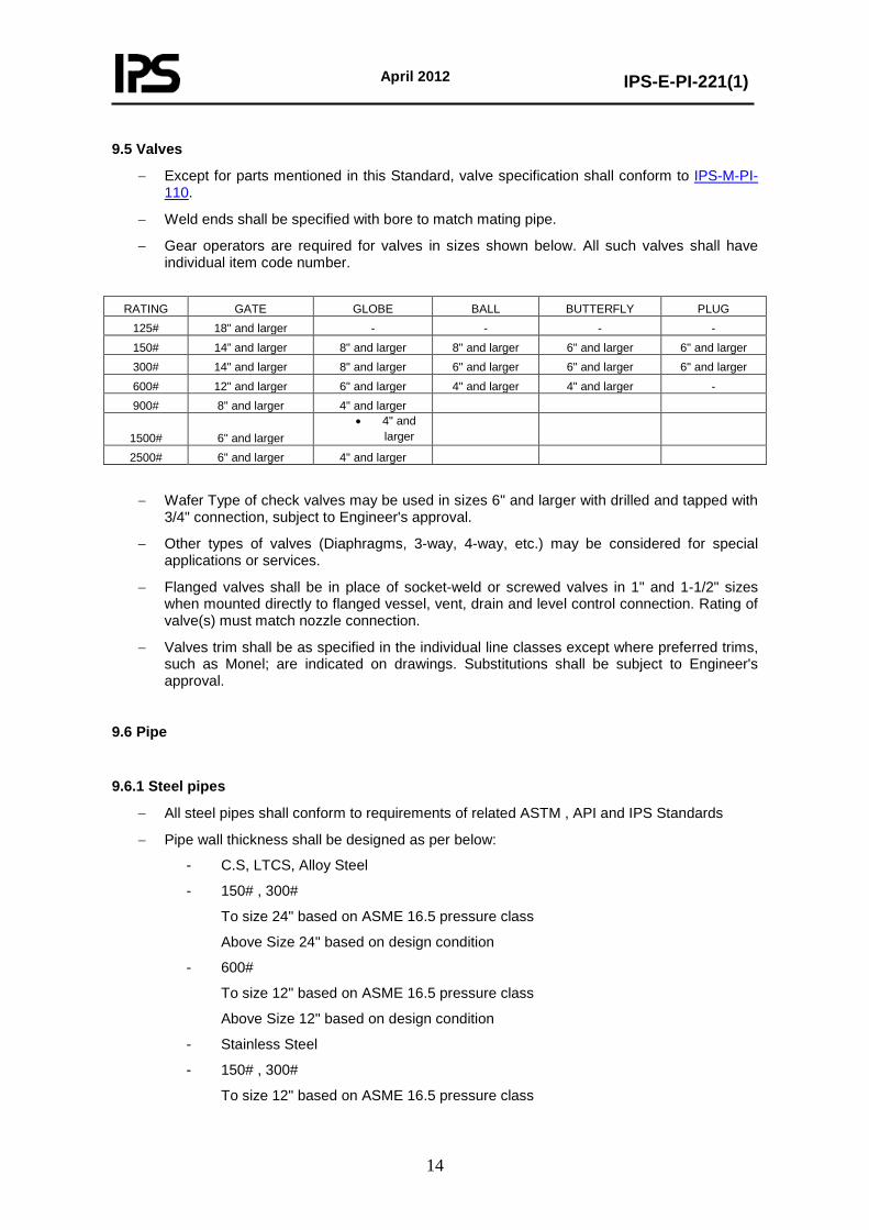
9.5 Valves
− Except for parts mentioned in this Standard, valve specification shall conform to IPS-M-PI-110.
− Weld ends shall be specified with bore to match mating pipe.
− Gear operators are required for valves in sizes shown below. All such valves shall have individual item code number.
RATING GATE GLOBE BALL BUTTERFLY PLUG
125# 18" and larger - - - - 150# 14” and larger 8" and larger 8" and larger 6" and larger 6" and larger 300# 14" and larger 8" and larger 6" and larger 6" and larger 6" and larger 600# 12" and larger 6" and larger 4" and larger 4" and larger - 900# 8" and larger 4" and larger
1500# 6" and larger • 4" and
larger
2500# 6" and larger 4" and larger
− Wafer Type of check valves may be used in sizes 6" and larger with drilled and tapped with 3/4" connection, subject to Engineer's approval.
− Other types of valves (Diaphragms, 3-way, 4-way, etc.) may be considered for special applications or services.
− Flanged valves shall be in place of socket-weld or screwed valves in 1" and 1-1/2" sizes when mounted directly to flanged vessel, vent, drain and level control connection. Rating of valve(s) must match nozzle connection.
− Valves trim shall be as specified in the individual line classes except where preferred trims, such as Monel; are indicated on drawings. Substitutions shall be subject to Engineer's approval.
9.6 Pipe 9.6.1 Steel pipes
− All steel pipes shall conform to requirements of related ASTM , API and IPS Standards
− Pipe wall thickness shall be designed as per below:
- C.S, LTCS, Alloy Steel
- 150# , 300#
To size 24" based on ASME 16.5 pressure class
Above Size 24" based on design condition
- 600#
To size 12" based on ASME 16.5 pressure class
Above Size 12" based on design condition
- Stainless Steel
- 150# , 300#
To size 12" based on ASME 16.5 pressure class
April 2012
IPS-E-PI-221(1)
15
Above Size 12" based on design condition
- 600#
To size 6" based on ASME 16.5 pressure class
Above Size 6" based on design condition
− The minimum thickness for C.S pipes up to 1 1/2" shall be schedule 80
− The minimum thickness for S.S pipes up to 1 1/2" shall be schedule 10S.
− For process and/or corrosive lines, C.S pipe up to 20" shall be seamless and above shall be LSAW.
− For non corrosive process and utility lines, C.S HFW/LSAW pipes may be used.
− Pipe ending: up to 2" shall be plain ends (PE) and above shall be bevel ends(BE).
− Pipe nipples for vents, drains, pressure tappings, sample points, (excluding connections from orifice flanges, carriers and other instrumentation) shall be minimum 100 mm length and sch 80 wall thickness.
9.7 Flanges and Fittings All pipe flanges and fittings shall conform to requirements of IPS-M-PI-150.
9.7.1 Fittings
− Long radius (R= 1.5 D) butt-welding elbows shall be used wherever possible. Unless otherwise specified, flanged elbows shall not be used.
− When weld fitting thickness is specified "Wall thickness to match pipe" fittings of commercially available weights shall be used, even though wall thickness of such fittings may be slightly greater than the pipe. Ends of fittings shall be taper bored if thickness exceeds pipe wall by more than 1/16".
− Butt-weld seamless fittings shall be used up to and including 20".
− Use 3000# screwed fittings (not seal-welded) for open end vent and drain piping downstream of block valves.
9.7.2 Flanges
− Raised Face (RF) flanges shall be used up to pressure rating 600# and for design temperatures not exceeding 450 oC .For above 600# and/or design temperatures exceeding 450 oC, ring type joint (RTJ) shall be used unless otherwise specified.
− All flanges shall be specified with bore to match I.D. of pipe.
− Slip-on flanges may be used where the following requirements are met :
i. Carbon steel piping
ii. Pipes handling non-toxic fluids
iii. Pressure - temperature conditions are within the ANSI 300 LB rating.
iv. Design temperature exceeds minus 20 oC
Slip-on flanges of austenitic stainless steel may be used within the limitations of item ii. through iv. above, if justified from the cost point of view.
April 2012
IPS-E-PI-221(1)
16
9.7.2.1 Flange facing finish − Flat face flanges shall be used for connecting flanges to flat face cast iron piping
components and equipment. In this case, gaskets shall cover the whole flange face.
− All raised face flanges shall be serrated and finished as indicated in table 1 of MSS-SP6.
9.8 Blinds
a) Thickness of blinds (spectacle or vapor) shall be in accordance with IPS-D-PI-120 and IPS-D-PI-148.
b) Spectacle Blind size DN 300 (NPS 12) and larger shall be supplied with jack screws.
9.9 Branch Connections
The principle is as follows:
Header of Lines / Branches / Use the Following 1 1/2" and Smaller / Reducing / Reducing Tee 1 1/2" and Smaller / Same Size / Equal Tee 2" and Larger / 1/2" through 1 1/2" / Sockolet, Therdolet 2" and Larger / Same Size / Equal Tee 2" to 24" / Reducing / Reducing Tee (According to ASME B 16.9) (1) 24" and Larger / Reducing (Up to 8") / Weldolet (2) 24" and Larger / Reducing (12" and above) / Reducing Tee (According to ASME B 16.9) (1)
Note 1:
Pipe to pipe/weldolet connection may be used instead of Reducing Tee unless otherwise specified.
Note 2:
If specified pipe to pipe connection may be used instead of weldolet.
− Reinforcement requirements for 90 degree pipe to pipe branch connections shall be checked against the design limits of the piping class in accordance with ASME B 31.3.
9.10 Pipe Bends
In the steam tracing lines, pipe bends (seamless pipe only) may be used in place of standard fittings unless otherwise indicated.
Bend radius of pipe shall be a minimum of 5 times the nominal diameter.
9.11 Thread Compound Thread compound requirements, unless otherwise specified in the individual Line Class, shall conform to the following:
Pipe Threads To 232 ºC Teflon Tape Above 232ºC Armite No. 250 “Led-plate”/ equivalent Bolt Threads For all lines 177ºC and higher Armite No. 250 “Led-plate”/ and for Line Classes 600# equivalent and higher
April 2012
IPS-E-PI-221(1)
17
9.12 Gaskets
- Gaskets shall be asbestos free material.
- For utility service up to 300# Non-Asbestos (Non-Graphite) Flat Sheet (Thk: 1.5 mm) should be used.
- For utility services above 300# and process lines up to 600# spiral wound gasket (Thk: 4.5 mm) shall be used.
- Spiral-wound gaskets on RFS flange must have internal retaining ring.
10. SELECTION OF BASIC MATERIAL
In consultation with the process designer or process engineer, the materials engineer shall establish the preferred materials selection based on the process requirements such as medium, pressure, temperature, flow and the environment of the process facility. Design life and cost considerations shall also be taken into account in this respect.
10.1 Corrosion allowance different from that shown in the line class shall be indicated on the related P & ID drawing.
10.2 Unless otherwise specified, Corrosion allowance shall be minimum 1.6 mm for CS and low Alloy Steel and 1 mm for S.S.
11. COLOR CODING
The materials shall be color coded as per project specifications.
12. MATERIAL NOT COVERED BY PIPING MATERIAL SPECIFICATIONS
Special piping items are referred to as SP's (Specialty Items). They are assigned an Item Code Number, listed in the specialty Item List and on P&I Diagrams.
13. RUBBER AND CEMENT LINING FOR PIPING SYSTEM
The general requirements for rubber/cement-lined piping system shall be according to IPS-E-TP-350 and IPS-C-TP-352.
14. PROVISION OF STRAINERS AND FILTERS
Provision of strainers and filter shall be in accordance with IPS-G-PI-230.
15. NON METALLIC PIPE AND FITTINGS
The general requirements for non metallic piping system shall be according to Appendix J of this IPS standard.
Note:
The company shall modify part II and III according to design basis as specified in this part (part I) of standard.

April 2012
IPS-E-PI-221(1)
18
APPENDICES
APPENDIX A
SUMMERY OF ISSUED PIPING CLASSES
Material
Piping
Class
ANS class rating 150 A
300 C
600 F
900 G
1500 H
2500 J
Carbon Steel N01 * * * * * * N02 * * N04 * * * * * N05 * * N06 * * N07 * * * * N09 * N10 * * * * * N12 * N14 * * * * N16 *
Alloy Steel P02 * * * * P04 * * * P05 * P06 * *
Stainless Steel S02 * * * * * S04 * * * S05 * * S06 * * * * S07 * * * *
Aluminum T Copper-based Alloys V Nickel & Nickel-based Alloys W Non-metallic Materials X01 * Carbon Steel with Lining Z01 *
Z02 * Z03 * Z04 * Z05 *
April 2012
IPS-E-PI-221(1)
19
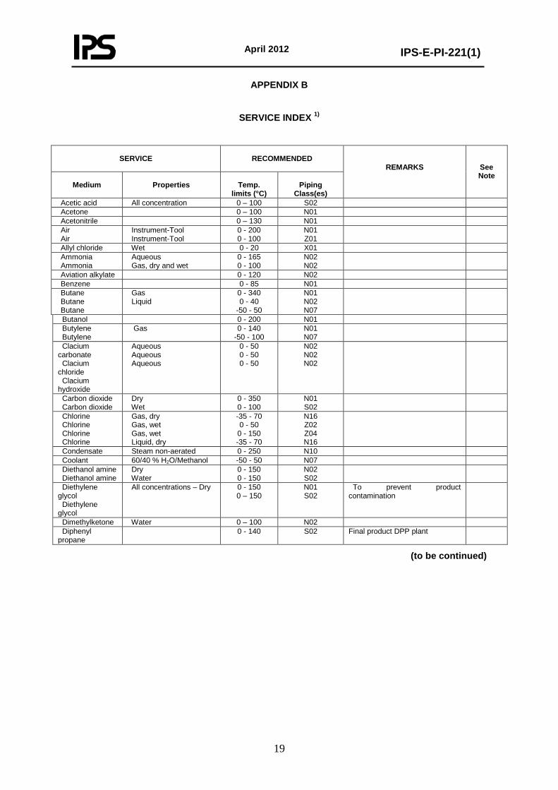
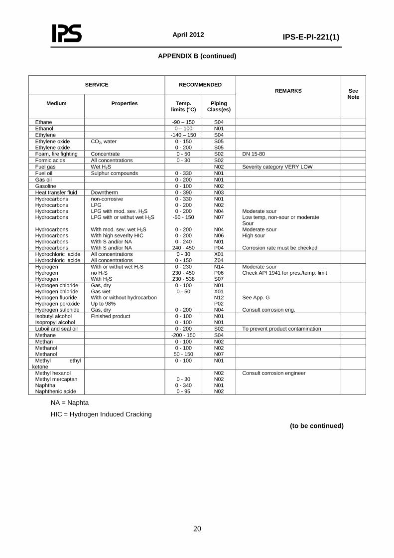
APPENDIX B
SERVICE INDEX 1)
SERVICE
RECOMMENDED
REMARKS
See Note
Medium
Properties
Temp.
limits (°C)
Piping
Class(es) Acetic acid All concentration 0 – 100 S02 Acetone 0 – 100 N01 Acetonitrile 0 – 130 N01 Air Air
Instrument-Tool Instrument-Tool
0 - 200 0 - 100
N01 Z01
Allyl chloride Wet 0 - 20 X01 Ammonia Ammonia
Aqueous Gas, dry and wet
0 - 165 0 - 100
N02 N02
Aviation alkylate 0 - 120 N02 Benzene 0 - 85 N01 Butane Butane Butane
Gas Liquid
0 - 340 0 - 40
-50 - 50
N01 N02 N07
Butanol 0 - 200 N01 Butylene Butylene
Gas 0 - 140 -50 - 100
N01 N07
Clacium carbonate Clacium chloride Clacium hydroxide
Aqueous Aqueous Aqueous
0 - 50 0 - 50 0 - 50
N02 N02 N02
Carbon dioxide Carbon dioxide
Dry Wet
0 - 350 0 - 100
N01 S02
Chlorine Chlorine Chlorine Chlorine
Gas, dry Gas, wet Gas, wet Liquid, dry
-35 - 70 0 - 50
0 - 150 -35 - 70
N16 Z02 Z04 N16
Condensate Steam non-aerated 0 - 250 N10 Coolant 60/40 % H2O/Methanol -50 - 50 N07 Diethanol amine Diethanol amine
Dry Water
0 - 150 0 - 150
N02 S02
Diethylene glycol Diethylene glycol
All concentrations – Dry 0 - 150 0 – 150
N01 S02
To prevent product contamination
Dimethylketone Water 0 – 100 N02 Diphenyl propane
0 - 140 S02 Final product DPP plant
(to be continued)
April 2012
IPS-E-PI-221(1)
20
APPENDIX B (continued)
SERVICE
RECOMMENDED
REMARKS
See Note
Medium
Properties
Temp.
limits (°C)
Piping
Class(es)
Ethane -90 – 150 S04 Ethanol 0 – 100 N01 Ethylene -140 – 150 S04 Ethylene oxide Ethylene oxide
CO2, water 0 - 150 0 - 200
S05 S05
Foam, fire fighting Concentrate 0 - 50 S02 DN 15-80 Formic acids All concentrations 0 - 30 S02 Fuel gas Wet H2S N02 Severity category VERY LOW Fuel oil Sulphur compounds 0 - 330 N01 Gas oil 0 - 200 N01 Gasoline 0 - 100 N02 Heat transfer fluid Downtherm 0 - 390 N03 Hydrocarbons Hydrocarbons Hydrocarbons Hydrocarbons Hydrocarbons Hydrocarbons Hydrocarbons Hydrocarbons
non-corrosive LPG LPG with mod. sev. H2S LPG with or withut wet H2S With mod. sev. wet H2S With high severity HIC With S and/or NA With S and/or NA
0 - 330 0 - 200 0 - 200
-50 - 150
0 - 200 0 - 200 0 - 240
240 - 450
N01 N02 N04 N07
N04 N06 N01 P04
Moderate sour Low temp, non-sour or moderate Sour Moderate sour High sour Corrosion rate must be checked
Hydrochloric acide Hydrochloric acide
All concentrations All concentrations
0 - 30 0 - 150
X01 Z04
Hydrogen Hydrogen Hydrogen
With or withut wet H2S no H2S With H2S
0 - 230 230 - 450 230 - 538
N14 P06 S07
Moderate sour Check API 1941 for pres./temp. limit
Hydrogen chloride Hydrogen chloride Hydrogen fluoride Hydrogen peroxide Hydrogen sulphide
Gas, dry Gas wet With or without hydrocarbon Up to 98% Gas, dry
0 - 100 0 - 50
0 - 200
N01 X01 N12 P02 N04
See App. G Consult corrosion eng.
Isobutyl alcohol Isopropyl alcohol
Finished product 0 - 100 0 - 100
N01 N01
Luboil and seal oil 0 - 200 S02 To prevent product contamination Methane -200 - 150 S04 Methan 0 - 100 N02 Methanol Methanol
0 - 100 50 - 150
N02 N07
Methyl ethyl ketone
0 - 100 N01
Methyl hexanol Methyl mercaptan Naphtha Naphthenic acide
0 - 30 0 - 340 0 - 95
N02 N02 N01 N02
Consult corrosion engineer
NA = Naphta
HIC = Hydrogen Induced Cracking
(to be continued)
April 2012
IPS-E-PI-221(1)
21
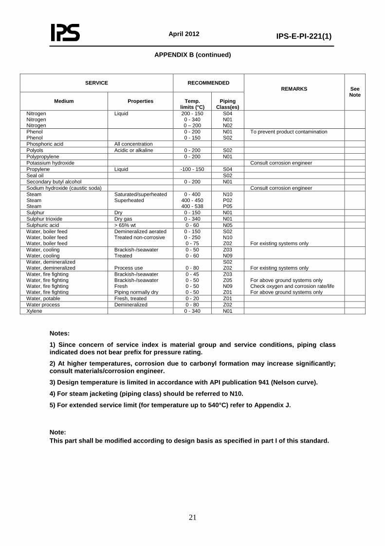
APPENDIX B (continued)
SERVICE
RECOMMENDED
REMARKS
See Note
Medium
Properties
Temp.
limits (°C)
Piping
Class(es) Nitrogen Nitrogen Nitrogen
Liquid 200 - 150 0 - 340 0 – 200
S04 N01 N02
Phenol Phenol
0 - 200 0 - 150
N01 S02
To prevent product contamination
Phosphoric acid All concentration Polyols Acidic or alkaline 0 - 200 S02 Polypropylene 0 - 200 N01 Potassium hydroxide Consult corrosion engineer Propylene Liquid -100 - 150 S04 Seal oil S02 Secondary butyl alcohol 0 - 200 N01 Sodium hydroxide (caustic soda) Consult corrosion engineer Steam Steam Steam
Saturated/superheated Superheated
0 - 400 400 - 450 400 - 538
N10 P02 P05
Sulphur Dry 0 - 150 N01 Sulphur trioxide Dry gas 0 - 340 N01 Sulphuric acid > 65% wt 0 - 60 N05 Water, boiler feed Water, boiler feed Water, boiler feed
Demineralized aerated Treated non-corrosive
0 - 150 0 - 250 0 - 75
S02 N10 Z02
For existing systems only
Water, cooling Water, cooling
Brackish-/seawater Treated
0 - 50 0 - 60
Z03 N09
Water, demineralized Water, demineralized
Process use
0 - 80
S02 Z02
For existing systems only
Water, fire fighting Water, fire fighting Water, fire fighting Water, fire fighting
Brackish-/seawater Brackish-/seawater Fresh Piping normally dry
0 - 45 0 - 50 0 - 50 0 - 50
Z03 Z05 N09 Z01
For above ground systems only Check oxygen and corrosion rate/life For above ground systems only
Water, potable Fresh, treated 0 - 20 Z01 Water process Demineralized 0 - 80 Z02 Xylene 0 - 340 N01
Notes:
1) Since concern of service index is material group and service conditions, piping class indicated does not bear prefix for pressure rating.
2) At higher temperatures, corrosion due to carbonyl formation may increase significantly; consult materials/corrosion engineer.
3) Design temperature is limited in accordance with API publication 941 (Nelson curve).
4) For steam jacketing (piping class) should be referred to N10.
5) For extended service limit (for temperature up to 540°C) refer to Appendix J.
Note: This part shall be modified according to design basis as specified in part I of this standard.
April 2012
IPS-E-PI-221(1)
22
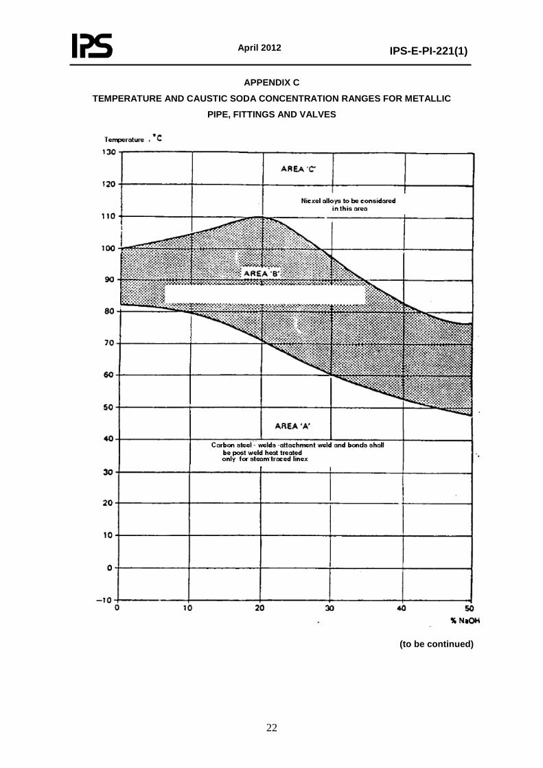
APPENDIX C
TEMPERATURE AND CAUSTIC SODA CONCENTRATION RANGES FOR METALLIC
PIPE, FITTINGS AND VALVES
(to be continued)

April 2012
IPS-E-PI-221(1)
23
APPENDIX C (continued)
GENERAL REQUIREMENTS FOR CARBON STEEL PIPING IN CAUSTIC SODA SERVICE Requirements to prevent caustic soda embritlement in carbon steel piping are given below: C.1 Design C.1.1 For area "A", non-heated lines, no requirements. C.1.2 For area "A", steam-traced lines, stress-relief for welds, attachment welds and cold-formed bends. C.1.3 For area "B", all lines, stress-relief for welds, attachment welds and cold-formed bends. C.1.4 Design piping systems for furnace post-weld heat treatment (pwht) preferably, i.e. with flanges, so as to enable placing in a furnace. C.1.5 Particularly intricate parts such as valve and pump manifolds should be designed for furnace pwht. C.1.6 If field pwht is unavoidable, ensure that areas and parts to be heat-treated, are readily accessible. C.1.7 Restrict the application of cold-formed parts resp. cold forming during fabrication. C.1.8 Exclude hot spots by direct wall-to-wall contact in the case of steam or electrical traced lines by application of spacers (ceramic, glass fiber or filled phenolic resin). C.1.9 Include the design of steam or electrical tracers. Fixation points for tracers to be at a distance of 6.5 m max. with special attention at bends and fittings. C.1.10 Drawings All drawings for the fabrication of carbon steel piping intended for caustic soda service shall be clearly marked "CAUSTIC SODA SERVICE". C.2 Fabrication C.2.1 Welding Inert gas or CO2-shielded arc welding shall be used for the root pass. Welds shall be made without excessive penetration (max. 2 mm) and shall be without grooves and/or craters. Pipework shall be inspected after welding. C.2.2 Installation Hanger supports shall be clamped around the pipes and bolted. Strips of CAF or glass-fiber material shall be applied between pipe and support. All indications given for the design of traced lines shall be followed closely. C.2.3 Ensure that all attachment welds are made before pwht is applied. C.3 Examination C.3.1 Visual examination of all welded piping parts shall be done during fabrication by an experienced inspector. C.3.2 A minimum of 10% of all welds shall be checked by radiography before post-weld heat treatment. All defects shall be repaired to fulfill minimum requirements.
(to be continued)
April 2012
IPS-E-PI-221(1)
24
APPENDIX C (continued)
C.4 Heat Treatment
C.4.1 Welds, attachment welds and cold-formed piping parts shall be given a stress relief post-weld heat treatment.
C.4.2 This heat treatment shall be carried out in a furnace or, if required, by electric induction heating.
C.4.3 Heat treatment shall be in the range of 580 to 620°C with a holding time of 3 minutes per mm thickness and a minimum holding time of 1 hour. Cooling shall be controlled at a rate of 100°C per hour down to 350°C.
C.4.4 The complete post-weld heat treatment cycle shall be recorded.
C.5 Testing
C.5.1 All piping parts shall be hydraulically tested after heat treatment.
C.5.2 The hydrostatic test pressure to be used shall be 1.5 times the maximum allowable pressure at ambient temperature, as mentioned in the relevant piping classes.
C.5.3 Ensure that draining and drying after testing is carried out properly.
C.6 Identification
C.6.1 All piping fabricated in accordance with this Standard shall be clearly identified by a suitable marking either by painting or fixing an adhesive tape around the parts.
C.6.2 Pipe class number and line designation shall be painted on each part.
April 2012
IPS-E-PI-221(1)
25
APPENDIX D GENERAL REQUIREMENTS FOR CARBON STEEL PIPING
IN SULPHURIC ACID SERVICE Carbon steel piping systems in sulphuric acid shall be designed in accordance with the rules given below: D.1 Design D.1.1 Flow rate Piping shall be sized for a nominal velocity of 0.75 m/s in straight ends. D.1.2 Flow changes Pipework design shall be studied carefully to avoid sudden changes in the directionflow, turbulences and extreme changes in velocity. D.1.3 Drainage falls Horizontal runs of pipework shall be avoided. Generous falls for self-draining purposes shall be provided for, wherever possible. The fall shall be minimum 1 cm/m. D.1.4 Pipe bends and elbows Pipe routings shall be studied with the aim to reduce the number of bends and to restrict the number of elbows to the bare minimum. Pipe bends shall have a radius R = 5 D where D is the nominal pipe diameter. Standard elbows, which shall be used for sweep-in connections, shall be long-radius type R = 1½ D. Short-radius elbows (R = D) shall not be used. D.1.5 Pipe reducing Reducers shall be avoided as much as possible. Where a reduction is necessary, the reducer shall be concentric, the reducing part shall be smooth and the reduced diameter bore shall correspond to the connecting part or be tapered to suit that bore. D.1.6 If reducing is upstream, an eccentric reducer may be considered to ensure the required fall for drainage. D.1.7 Junctions Pipework shall be designed to avoid 90° tee junctions, instead 45° laterals; Y-type or sweep-in junctions shall be used. D.1.8 Spool pieces Whenever turbulences or considerably higher velocities cannot be avoided, the use of spool pieces shall be considered. These can be made out of solid, fully-resistant alloys or carbon steel, lined with fully-resistant material. Length of spool pieces to be L = 20 D where D is the nominal pipe diameter.
(to be continued)
April 2012
IPS-E-PI-221(1)
26
APPENDIX D (continued) D.1.9 Post-weld heat treatment Pipe sections of intricate shapes, which are not accessible for finishing and/or where turbulences and velocity changes are most likely, e.g. valve and pump manifolds, shall be designed as flanged sections, such to enable pwht in a furnace. D.1.10 Butt welding Pipework shall be designed to restrict the number of butt welds which are not accessible for finishing and inspection of the inner surface. Misalignment of individual and adjoining pipe bores shall not exceed 0.3 mm. D.1.11 Flanges Flanges shall be installed to enable access to welds for finishing and to fabricate flanged pipe sections, junctions, reducers and other special pipe parts. Welding neck flanges shall be used. In exceptional cases the use of slip-on flanges may be considered. D.1.12 Gaskets Flat ring gaskets, with ID dimensions exactly equal to the bore of the pipes shall be used. The OD dimensions shall be in accordance with ANSI/ASME B 16.21. Gasket thickness to be 1.5 mm. Gasket material to be specified for sulphuric acid service. Attention shall be given that not all acid-resistant type gaskets are suitable. D.1.13 Drawings All drawings for the fabrication of carbon steel piping intended for acid service shall be clearly marked "SULPHURIC ACID SERVICE". D.2 Welding Inert gas or CO2 shielded arc welding shall be used for the root pass. Where the weld metal penetrates to the bore of the pipe and/or fitting, great care shall be taken to ensure full penetration without excess penetration. The internal bore at the location of the welds shall be dressed flush with the inner pipe wall. Permanent backing rings shall not be used. D.3 Examination D.3.1 Visual examination of all welded piping parts shall be done during fabrication by experienced inspectors. D.3.2 A minimum of 10% of all welds shall be checked by radiography. Radiographing shall be done after the welds have been dressed. All defects shall be repaired to fulfill the minimum requirements. D.4 Heat Treatment D.4.1 A normalizing heat treatment shall be applied to sections of intricate shape, e.g. valve and pump manifolds, and sections where high heat input on welding or extreme stresses on forming have been introduced.
(to be continued)
April 2012
IPS-E-PI-221(1)
27
APPENDIX D (continued)
D.4.2 Heat treatment conditions:
- normalizing temperature 900-930°C;
- holding time 3 minutes per mm thickness with a minimum of 1 hour;
- cooling in still air.
Attention shall be paid to adequate support of the piping sections during normalizing to prevent excessive deformation and/or warping.
D.5 Testing
D.5.1 All piping parts shall be hydrostatically tested after post-weld heat treatment.
D.5.2 The hydrostatic test pressure to be used shall be 1.5 times the maximum allowable pressure at ambient temperature, as mentioned in the relevant piping classes.
D.5.3 Ensure that draining and drying after testing is carried out properly.
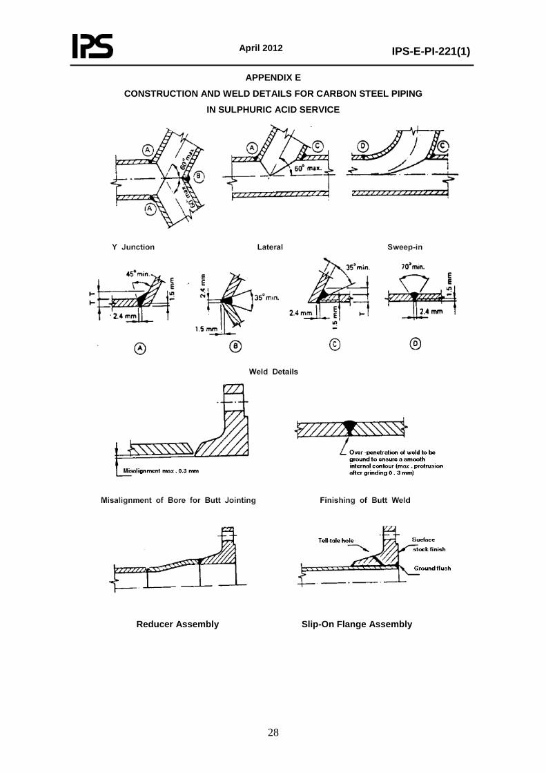
April 2012
IPS-E-PI-221(1)
28
APPENDIX E
CONSTRUCTION AND WELD DETAILS FOR CARBON STEEL PIPING
IN SULPHURIC ACID SERVICE
Reducer Assembly Slip-On Flange Assembly
April 2012
IPS-E-PI-221(1)
29
APPENDIX F
GENERAL REQUIREMENTS FOR CARBON STEEL PIPING
IN DRY CHLORINE SERVICE
This Appendix provides requirements for the design, and testing of piping systems for "dry" chlorine, in either the liquid or gaseous phase, at temperatures between -50°C and +70°C. "Dry" chlorine contains less than 150 mg/kg water.
F.1 Design
F.1.1 Materials for process piping in chlorine service, are specified in piping Class CN16. Liquid chlorine shall be considered to be a "(toxic) lethal" substance.
F.1.2 Only schedule 80 seamless pipe of minimum DN 20 (NPS ¾) should be used to ensure rigidity and protection against mechanical damage which may result in leaks.
F.1.3 Piping DN 25 (NPS 1) is adequate for all normal flows.
F.1.4 Piping arrangements shall be as simple as possible, with a minimum of welded or flanged connections. For piping of DN 100 (NPS 4) and smaller, elbows shall preferably be made by bending. Threaded joints shall not be used. All welds shall be butt welds. No socket welding fittings, bosses and weldolets shall be used where a fillet weld will be applied.
F.1.5 Liquid chlorine has a high coefficient of thermal expansion. If liquid chlorine is trapped between two valves, and expands enough pressure is created to burst the pipe. Therefore each line or line section shall have an expansion chamber, a pressure relief valve or rupture disc discharging to a receiver.
The expansion chamber capacity shall have at least 20% of the section volume and be based on a temperature rise of 27°C above the ambient temperature.
F.2 Manufacturing
F.2.1 Assembly of piping components
For the assembly of all piping components, pipe ends, fittings and welding neck flanges to be butt-welded, a uniform root opening, as specified below, is required:
NOMINAL PIPE SIZE
ROOT OPENING
Smaller than DN 50 (2 in.)
DN 50 - 250 (2-10 in.) DN 300 (12 in.) and larger
1.5 mm 1.5-2.5 mm 2.5-3.5 mm
F.2.2 Alignment
Alignment shall be in accordance with ANSI B 31.3 but with the exception that the internal trimming shall be 1:4, instead of 30°C.
(to be continued)
April 2012
IPS-E-PI-221(1)
30
APPENDIX F (continued) F.2.3 Bending
1) Pipes may be bent in the hot or cold condition. 2) A normalizing heat treatment shall be applied if the Flattening deformation is more than 5%. 3) No heat treatment is required for hot-formed bends upon which the final forming operation is completed at a temperature above 620°C and below 950°C provided they are cooled in still air. When hot bending is carried out outside the temperature range given above, a separate normalizing heat treatment at 900-950°C is required.
F.2.4 Welding
- Field welds shall be kept to a minimum and shall be carried out under fair weather conditions only. - Permanent backing rings shall not be used. - Post-weld heat treatment is not required. - Cracked tack welds shall be removed using the same procedure. - Temporary tack welds should not touch the root gap or the root face. - For temporary tack welding, the use of "bridge pieces" is recommended to avoid damage to the root face of the gap area.
Welding processes - For pipe sizes DN 50 (2 in.) and smaller, the "gas Tungsten arc welding process" shall be applied. Larger sizes should be "gas Tungsten are welding", but shielded metal are welding may be used. Procedures and welders shall be qualified and approved by the principal before actual production welding starts. Welding consumables - An alternative possibility is the procurement of consumables directly from the manufacturer complete with certificates. These certificates should give information per batch on chemical composition and mechanical properties of the weld deposit. Final approval of welding consumables for a particular job will follow through meeting the test requirements of the welding procedure qualification. Inspection of welds - All welds shall be 100% radiographed. The method of radiography to be employed for inspection should be in accordance with ASME Section V. Acceptance criteria of welds shall be in accordance with ANSI B 31.3, Table 327.4.1A "Limitation on Imperfections in Welds". F.3 Hydrostatic Testing The hydrostatic testing shall be carried out according to IPS-C-PI-350 before the system is cleaned and dried. For piping Class CN16 the hydrostatic test pressure shall be at least 45 bar (1.5 times the pressure of the service limits).
(to be continued)
April 2012
IPS-E-PI-221(1)
31
APPENDIX F (continued)
F.4 Final Cleaning and Drying after Welding and Testing
F.4.1 Chlorine may react with oil. Therefore, in addition to requirements cited in IPS-C-PI-410 cleaning shall be accomplished by pulling through each pipe section a cloth saturated with trichloroethylene or other suitable chlorinated solvent. Hydrocarbons or alcohol shall never be used, because remnants of these solvents react with chlorine.
Cleaning and drying are accomplished by passing steam through the line from the high end until the entire line is hot to the touch (approximately 60°C). Condensate and any foreign particles (such as oil or metal) shall be drained out after the steam supply line has been disconnected and all pockets and low spots have been drained.
While the line is still warm, dry air shall be blown through the line until the dew point of the discharged air is the same as that of the air blown into the system, e.g. minus 40°C or below. When drying is finished, the line shall be kept closed in order to prevent re-entry of atmospheric moisture.
F.4.2 Gas testing
The dried piping system shall be pressurized to 10 bar ga with dry air or nitrogen and tested for leaks by the application of soapy water to the outside of joints. Afterwards, chlorine gas may be introduced and the system re-tested for leaks as described below.
F.4.3 Detection of chlorine leaks
The location of a leak in a chlorine-containing system can be detected by the reaction of ammonia vapor with the escaping chlorine. The reaction gives a dense white cloud.
The most convenient way is to direct the ammonia vapor at the suspect leak employing a plastic squeeze bottle containing aquous ammonia. Do not squirt liquid aquous ammonia on pipe and fittings.
F.4.4 Repairs
Repairing a leak may require welding. Before any welding is started, all piping shall be thoroughly purged and checked for the thoroughness of the purge (inside and around the pipe) with an explosion meter. Carbon steel ignites in chlorine of 250°C, thus welding without purging could start a fire. Purge with dry air and continue a small flow of air during the welding operation.
April 2012
IPS-E-PI-221(1)
32
APPENDIX G
GENERAL REQUIREMENTS FOR PIPING IN
HYDROGEN FLUORIDE (HF) SERVICE
G.1 General
Mixtures of hydrogen fluoride, hydrocarbons (and some water) as they occur in the HF alkylation process for the production of iso-octane and detergent alkylates. The following mixtures can be contained in carbon steel:
- Hydrocarbons 33% HF and traces of water up to 70°C and 6 bar,
- Hydrocarbons 4% HF and traces of water up to 160°C and 3 bar.
- Hydrocarbons and traces of HF, up to 200°C and 3 bar.
G.2 Design
Piping Classes:
Class CN12 ASTM A 333 Gr. 6, 3 mm corrosion allowance, temperature limits 0-200°C, specially meant for operation below 45°C.
G.2.1 Hydrogen fluoride is considered a lethal substance, and all piping that operates below 45°C or may reach such low temperatures during any stage in operation shall be made of notch-ductile materials. Classes CN12 fulfill that requirement.
G.2.2 The use of bellows is prohibited. Screwed connections shall not be used, all connections shall be welded or flanged. Flange connections shall be reduced to the least possible number to avoid leakages.
G.2.3 Most bolting materials (Cr-Mo steel, stainless steel, Monel) may be susceptible to stress corrosion cracking if exposed to HF. Therefore flanged connections shall not be permitted to leak and the edge of all flanges shall be painted with one coat of Socony HF Detecting Paint No. 20-Y-15 for the detection of HF leaks. Hence, flanges shall not be insulated.
G.2.4 For safe and easy handling during operation and (downhand) maintenance all valves and instruments shall be located at an elevation of maximum 1 meter above the floor.
G.2.5 To avoid that possible deposition of iron fluoride may hamper the operation, the valve types shall be selected as follows:
- Globe valves with Monel trim and soft seats (PTFE) for valves in normally closed position.
- Ball valves with Monel Ball and seats for valves in normally open position.
G.2.6 All HF service piping shall be installed above grade and shall be self-draining to the necessary low point bleeders.
To minimize the number of low point bleeders, piping should drain into equipment if possible (vessels, heat exchangers, pumps, control valves).
G.2.7 Process line size should be minimum DN 25. Drains, vents, bleeders, etc., may be made minimum DN 20. All control vales in HF service shall be installed with block valves and by-pass globe valve and shall have a flush connection on either side of the control valves. Gage glasses shall be provided with a protective cover of KEL-F or PTFE.
G.2.8 Equipment in HF Service is normally post-weld heat treated, this is not required for piping.
(to be continued)
April 2012
IPS-E-PI-221(1)
33
APPENDIX G (continued)
G.3 Identification
All piping fabricated to this Standard shall be identified by a clear and suitable marking, either by painting or fixing an adhesive band around the pipe.
Pipe class number and line designation number shall be painted on each pipe piece.
G.4 Operation and Maintenance
The wearing of protective clothes, gloves, goggles, etc., shall be prescribed and it shall be ensured that all safety instructions are strictly observed.
Before breaking flanges of piping that have been in HF service neutralization by means of ammonia or sodium bicarbonate is required to prevent HF contact with the skin. Even if no severe corrosion is experience fouling and heavy iron fluoride deposits are often present.
Neutralization of such thick fouling layers is rather difficult and upon subsequent mechanical removal acidic conditions may again be encountered underneath due to insufficient neutralization. If the acidity is such that it is unsafe to continue work, a second neutralization is recommended.
April 2012
IPS-E-PI-221(1)
34
APPENDIX H GENERAL REQUIREMENTS FOR RUBBER LININGS
FOR PROCESS EQUIPMENT AND PIPING H.1 SCOPE This Appendix covers both the general requirements for the purchase and related testing, inspection transportation and storage of vulcanized and non-vulcanized rubber-lined process equipment and piping, both shop fabricated and in-situ. H.2 MATERIALS H.2.1 General The following rubber types are used for lining purposes (classification in accordance with ASTM D 1418):
- Natural rubber (NR) - Synthetic polyisoprene rubber (IR) - Styrene-butadiene rubber (SBR) - Chloroprene rubber (CR) - Butyl rubber (IIR) - Nitrile rubber (NBR) - Ethylene propylene rubber (EPM and EPDM) - Urethane rubber - Chlorosulphonated polyethylene (CSM)* - Fluoro rubber of the polymethylene type (FKM)** * Commercially available under the registered trade mark "Hypalon" ** Commercially available under the registered trade mark "Viton"
Ebonites are rubbers with a hardness value of at least 60° Type D Shore and can be produced from NR, IR, SBR, NBR or blends thereof. H.2.2 Material Selection The final selection of the type and thickness of the rubber lining, and the method of application, shall be made in conjunction with the materials specialist and the lining contractor. The following details shall be included on the requisition of the equipment concerned: - products to be handled
- temperature minimum, maximum, normal . - degree of vacuum or pressure - cycle of operations - abrasion and erosion aspects - immersion conditions.
H.2.3 Quality of Rubber The grade of rubber shall be specified on the requisition sheet. The lining contractor shall state that the lining will satisfy the chemical and physical conditions specified with respect to the agreed service lifetime. The manufacturer shall supply the specification for the approved rubber compound and samples of the vulcanized rubber sheet for test and reference purposes. The specification of the rubber compound shall not be changed without prior written approval from the principal.
(to be continued)
April 2012
IPS-E-PI-221(1)
35
APPENDIX H (continued) H.3 DESIGN AND FABRICATION H.3.1 General The fabrication of the equipment shall be in accordance with BS 6374: Part 5 or DIN 28051 and DIN 28055. The important points are:
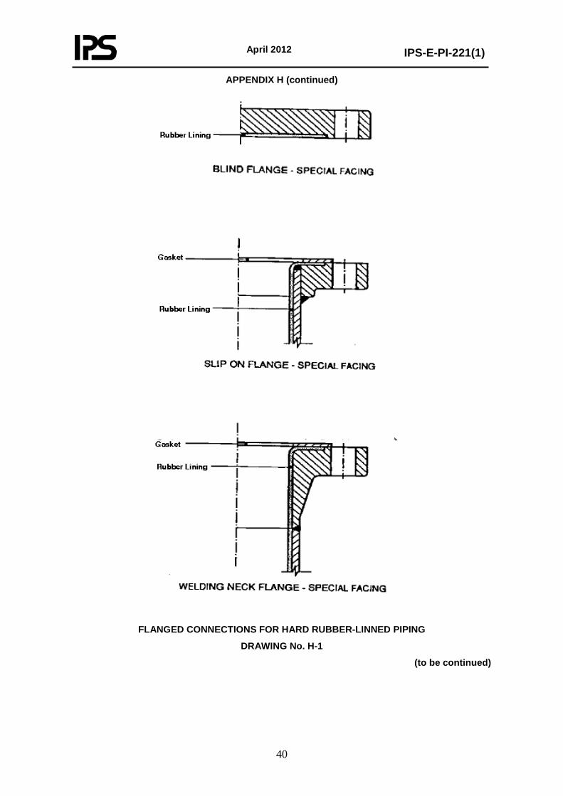
- the surface must be accessible for manual working; - the weld seams must be continuous, smooth and free from pores and, if necessary, machined or ground (H.3.3); - (steel) reinforcements should, if possible, be situated on the outside.
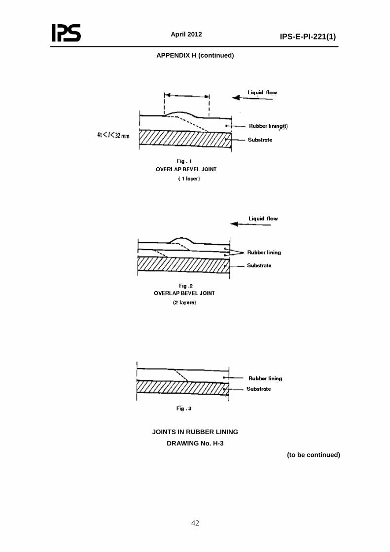
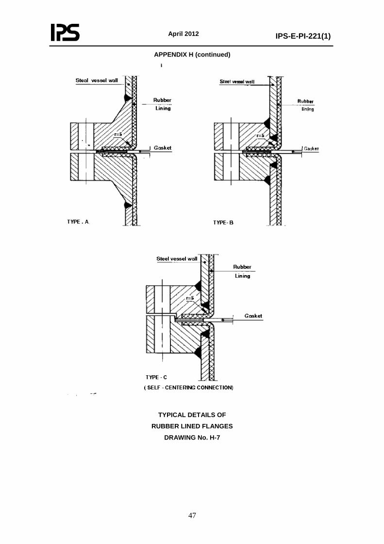
All branches shall be flanged and the lining shall be taken over the flange face to prevent ingress of the process liquid behind the lining. For typical flanged connections in equipment see Drawing No. H-7. For typical flanged connections in piping see Drawing Nos. H-1 and H-6. For standard lengths and dimensions of piping and piping elements see Drawing Nos. H-4 and H-5. Sharp changes of contour in the surface to be lined shall be finished to a suitable radius, such that the internal radius of the lining not less than 3 mm. Air vent holes to prevent air trapped in welded joints may sometimes be necessary, see Drawing No. H-2. H.3.2 Surface Finish of Substrate The surface to be lined shall be smooth, free from pitting, cavities, porosity, or other surface irregularities in accordance with DIN 28053. The surface shall also be free from oil, grease and other foreign matter. Metallic surfaces shall be blast-cleaned to a surface finish corresponding to SA 2.5 in accordance with ISO 8501-1. After this operation the surface roughness shall have a peak-to-valley height of 40 µm-100 µm, with an average of 50 µm. Immediately after the blast cleaning of the metallic substrate the grit, dust etc. shall be removed and a layer of adhesive primer with a dry-film thickness of approximately 30 µm shall be applied. H.3.3 Welds in Metal Substrate All metal-to-metal joints shall be made by welding. Welds shall be homogeneous and free of pores. Welds shall be ground smooth and flush with the parent metal on the side to be covered. Wherever possible, they shall be made from the side to be lined. Where this is not possible, the root shall be chipped out and a sealing run shall be applied. Internal corner and tee joints shall be welded with full penetration. Welds shall be ground smooth and concave to the required radius (H.3.1). Welds shall be examined according to applicable design codes. Drawing No. H-2 shows acceptable welding details. H.3.4 Joints in Rubber Lining Overlap joints as shown in Fig. 1 of Drawing No. H-3 shall be used when joining separate sheets of unvulcanized rubber. The total contacting surface between the sheets shall be a minimum of four times the sheet thickness but shall not exceed 32 mm at any point. Where applicable, overlaps shall the direction of the liquid flow.
(to be continued)
April 2012
IPS-E-PI-221(1)
36
APPENDIX H (continued) When the total lining thickness is built up from more than one layer, only the joints in the top layer shall be of the overlap bevel type, the under layers being flush-jointed as shown in Fig. 2 of Drawing No. H-3. The relatively weak flush joint (Fig. 3 of Drawing No. H-3) is applied when the lining is used as a base for chemical-resistant brick lining. Joints in the different layers shall be staggered. Joints between rubber pipe linings and the rubber on the flange facing shall not protrude so as to restrict the bore of the pipe or to prevent efficient sealing between the flange faces of adjacent lengths. H.3.5 Gaskets The selection and application of the gasket material shall be in accordance with the service conditions. Generally for hard rubber linings a soft rubber gasket is used and for soft rubber linings a CAF gasket is used. To prevent the gasket and lining bonding together, the rubber flange facing should be lightly rubbed with colloidal graphite. H.3.6 Painting Unless otherwise stated, all parts which are not rubber-lined shall be degreased and blast-cleaned and painted with one coat of a suitable epoxy resin-based primer. This shall be carried out after vulcanization of the rubber. H.3.7 Lining Application Manufacturer’s procedures for the application of the lining shall be adhered to. However, if shop vulcanization is used, the adhesive primer shall be applied immediately after preparation of the substrate. The pre-cut unvulcanized rubber sheets shall be applied without inclusion of air and with specified joints within 96 hours. If in-situ vulcanization is carried out, the surface to be lined shall have a temperature during the application of the unvulcanized rubber sheets not lower than 10°C and the relative humidity should not be higher than 75%, i.e. water condensation on the surface shall be prevented during application. The manufacturer shall be responsible for the type of the adhesive system used to bond the rubber lining to the substrate. He shall produce evidence that the adhesive system is suitable for the service conditions and will produce the bond required between rubber and substrate when the rubber is applied under the conditions of vulcanization. H.4 QUALIFICATION TESTING H.4.1 General The principal will indicate at the time of enquiry or order whether qualification testing is required before delivery in order to establish the capabilities of the manufacturer or, for example, because of time elapsed or new developments. At the request of the manufacturer, and after approval by principal, the tests required may be performed on products from current running stock. The number and size of the samples and the method of sampling shall be established by agreement between the manufacturer and the principal. Tests may be performed by the manufacturer or by an independent testing organization. In both cases a certificate stating the test results shall be submitted. DIN 50049 3.1 B is acceptable for this purpose. When the equipment is subject to a test pressure greater than 0.5 barg, the lining shall be carried out after hydrotesting.
(to be continued)
April 2012
IPS-E-PI-221(1)
37
APPENDIX H (continued) H.4.2 Rubber Lining H.4.2.1 Rubber quality It shall be verified that the type of rubber is correct (H.2.3). Test method ASTM D 3677 may be used for identification. H.4.2.2 Performance of rubber The manufacturer shall certify that the quality of the rubber will satisfy the chemical and physical conditions to which it will be exposed for the agreed operating life. H.4.2.3 Physical properties The physical properties of the vulcanized rubber shall comply with the values given by the manufacturer. The test methods as described in BS 903:part A2 are acceptable. These tests are carried out on separately supplied test samples. All hardness readings shall conform to the specified value within plus/minus 5°. A minimum of three readings shall be taken for each square metre of lining. For large surfaces the maximum number of readings shall be agreed upon by the manufacturer and the principal. In general, it is common to express hardness in Durometer A or Durometer D readings in accordance with ASTM D 2240. H.4.3 Rubber-Lined Parts H.4.3.1 Surface defects Linings shall be free from blisters larger than 10 mm in diameter, cracks or other surface imperfections, porosity, voids or inclusions. H.4.3.2 Adhesion For the determination of the adhesion to the metal substrate, samples shall be prepared from the same rubber compound used for the lining and the same metal. The pretreatment of the metal sample shall be identical to the pretreatment of the surface of the equipment or piping. After the same vulcanization procedure, the adhesion shall be determined according to method A (for ebonites) and to method B (for soft rubbers) as described in ASTM D 429. The adhesion value calculated from the load at failure and the original bonded area shall be as agreed upon in the specification. However, unless otherwise agreed, they shall be at least 10 N/mm2 (method A) and 4 N/mm2 (method B) respectively. H.4.3.3 High-voltage spark The continuity of the lining on metallic substrates shall be checked with a high-voltage spark test. Sparks shall not be produced when the lining is tested with a direct-current apparatus, using a voltage which is determined by the following formulas:
6 (1 + thickness in mm) kV which shall not exceed 30 kV. This voltage should be adjusted for high carbon black filled (soft) rubbers to approximately 3 kV per mm thickness (exact voltage to be determined on a test sample). It is not possible to inspect antistatic linings with this test. In this case, after consultation with the Principal, the "wet sponge test", a low-voltage holiday detector shall be used.
(to be continued)
April 2012
IPS-E-PI-221(1)
38
APPENDIX H (continued)
Both the methods describing the continuity testing in BS 6374:Part 5 for high frequency with an AC source and the high-voltage test in DIN 55670 are acceptable to the Principal.
H.4.3.4 Thickness
The thickness of the lining applied on substrates shall be determined with a thickness meter and shall conform to the agreed thickness with a minimum of 90% of that thickness. A minimum of three measurements per square metre shall be made. For large surfaces the maximum number of readings shall be agreed between the manufacturer and the Principal.
H.5 ACCEPTANCE TESTS AND CERTIFICATION
H.5.1 Tests
The inspector representing the Principal shall check at random whether the rubber-lined process equipment and piping meets the requirements mentioned in (H.4). In addition, the following acceptance tests shall be carried out.
if the requirements are not achieved, even after re-vulcanization, the rubber-lined item shall be rejected.
H.5.1.1 Visual inspection
The rubber lining shall be free from cracks or any other imperfections. Blisters smaller than 10 mm diameter are acceptable, unless otherwise specified. Minor wrinkles and surface markings which will not have a significant effect on the performance of the lining are also acceptable.
The total amount of repairs shall not be more than 100 cm2 per square metre of lined surface. Lining repairs are not allowed in piping, on flange facings or on nozzle necks of equipment.
Repair of damaged rubber linings shall only be carried out by the contractor after consultation with and the agreement of the Principal.
H.5.1.2 Adhesion
The adhesion between the rubber lining and the substrate shall be homogeneous and without any defect. This may be investigated by lightly tapping the rubber lining with an appropriate wooden hammer. At areas where the adhesion is broken, a hollow sound will occur.
H.5.1.3 Thickness
The thickness of the rubber lining applied on carbon steel substrates shall be determined and shall conform to the thickness as mentioned on the requisition form with a minimum of 90% of that thickness. A minimum of three measurements per square metre shall be made.
H.5.1.4 Hardness
The hardness shall conform to the value specified on the requisition within a tolerance of plus/minus 5°. A minimum of three readings per square metre shall be taken.
(to be continued)

April 2012
IPS-E-PI-221(1)
39
APPENDIX H (continued)
H.5.1.5 Continuity of the lining
The continuity of the lining shall be checked according to (H.4.3.3); however, using a reduced voltage determined by the following formula:
4 (1 + thickness in mm) kV.
H.5.1.6 Hydraulic testing
If applicable, equipment and piping shall be tested hydraulically at a pressure equal to the test pressure mentioned in the appropriate design code, and at the maximum allowable service temperature for the particular lining. These conditions shall be maintained for a period of 1 hour. At the end of the test, the lining shall be visually inspected. Blisters, cracks or other surface irregularities are not permitted. Thereafter the lining shall pass the high-voltage spark test.
H.5.1.7 Vacuum testing
If applicable, the equipment and piping shall be tested at a vacuum of 130 mbar absolute at ambient temperature for a period of 1 hour. After this test no visible defects shall be permitted in the lining.
H.5.1.8 Flange alignment
The flatness of the lining applied on the gasket contact surfaces shall be determined with a stretcher and shall be within a tolerance of plus/minus 0.3 mm.
H.5.2 Certification
The manufacturer shall keep complete qualitycontrol and test reports. He shall submit a certified record of inspection and testing, together with a statement of compliance with these requirements. These shall include the certificates of the steel parts.
H.6 TRANSPORT AND STORAGE
Lined piping shall be packed in a manner which will ensure that no damage to the lining, including its edges, can occur. Rubber-lined equipment and piping shall not be transported or assembled if ambient temperature is below, or is likely to drop below, 0.°C. The objects shall be handled with care: hoisting shall be carried out using non-metallic slings. In particular branches, openings and flange facings are vulnerable and shall be protected adequately, e.g. by wood.
All rubber-lined items shall be clearly and permanently marked on the outside "RUBBER-LINED, HANDLE WITH CARE".
Rubber-lined equipment and piping shall be stored indoors or under cover. Allowance shall be made for free air circulation. Soft supporting material shall be used, e.g. wood or rubber. The objects shall not be exposed to direct heat or UV radiation. If this cannot be avoided owing to prevailing conditions, the items shall be kept filled with water until taken into use. Freezing of this water shall be prevented.
(to be continued)
April 2012
IPS-E-PI-221(1)
40
APPENDIX H (continued)
FLANGED CONNECTIONS FOR HARD RUBBER-LINNED PIPING
DRAWING No. H-1
(to be continued)

April 2012
IPS-E-PI-221(1)
41
APPENDIX H (continued)
AIR VENT HOLES AND WELDING DETAILS
DRAWING No. H-2
(to be continued)
April 2012
IPS-E-PI-221(1)
42
APPENDIX H (continued)
JOINTS IN RUBBER LINING
DRAWING No. H-3
(to be continued)
April 2012
IPS-E-PI-221(1)
43
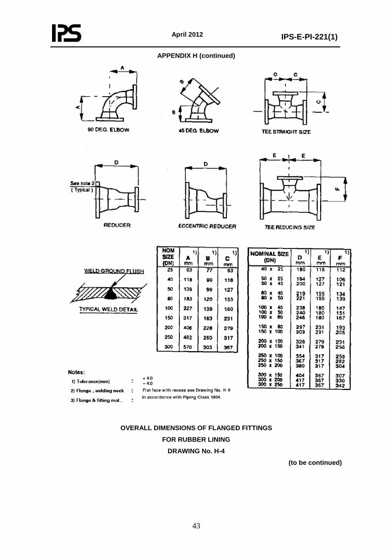
APPENDIX H (continued)
OVERALL DIMENSIONS OF FLANGED FITTINGS
FOR RUBBER LINING
DRAWING No. H-4
(to be continued)
April 2012
IPS-E-PI-221(1)
44
APPENDIX H (continued)
Run pipe Nom. size (DN)
1), 2)
L1 - mm
2)
L2 - mm
2)
L3 - mm
Outlet - Tee Nominal Size (DN)
25 40 50 80 100 150 200 250 300 2)
L4 – mm
Outlet - pipe to pipe connection Nominal Size (DN)
25 40 50 80 100 2)
L5 – mm
25 40 50 80 100 150 200 250 300
1000 3000 4000 5000 6000 6000 6000 6000 6000
93 118 127 155 180 231 279 317 367
-- -- --
120 120 140 150 150 175
93 112 106 -- -- -- -- -- --
-- 118 121 134 147 -- -- -- --
-- --
127 139 151 -- -- -- --
-- -- --
155 167 193 -- -- --
-- -- -- --
180 205 231 259 --
-- -- -- -- --
231 256 282 307
-- -- -- -- -- --
279 304 330
-- -- -- -- -- -- --
317 342
-- -- -- -- -- -- -- --
367
-- -- --
150 165 200 225 250 275
-- -- -- -- --
200 225 250 275
-- -- -- -- --
200 225 250 275
-- -- -- -- -- --
225 250 275
-- -- -- -- -- -- -- --
275 OVERALL DIMENSIONS OF FLANGED PIPING
FOR RUBBER LINING DRAWING No. H-5 (Page 1)
(to be continued)
April 2012
IPS-E-PI-221(1)
45
APPENDIX H (continued)
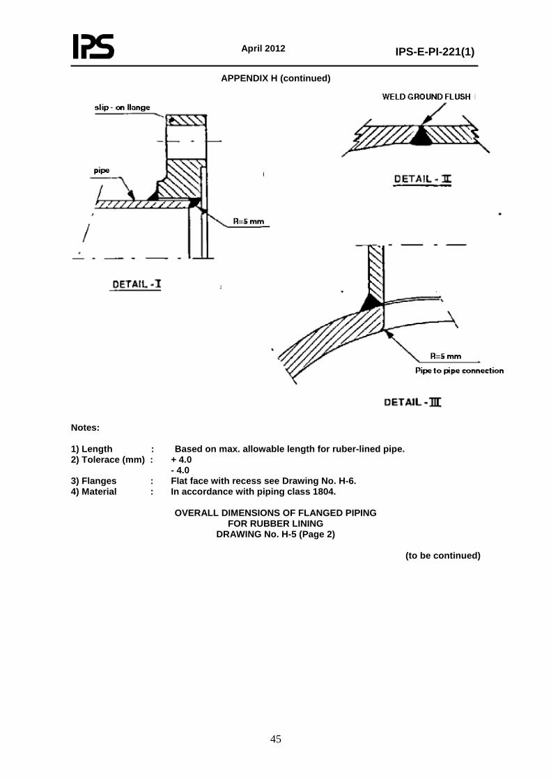
Notes: 1) Length : Based on max. allowable length for ruber-lined pipe. 2) Tolerace (mm) : + 4.0 - 4.0 3) Flanges : Flat face with recess see Drawing No. H-6. 4) Material : In accordance with piping class 1804.
OVERALL DIMENSIONS OF FLANGED PIPING
FOR RUBBER LINING DRAWING No. H-5 (Page 2)
(to be continued)
April 2012
IPS-E-PI-221(1)
46
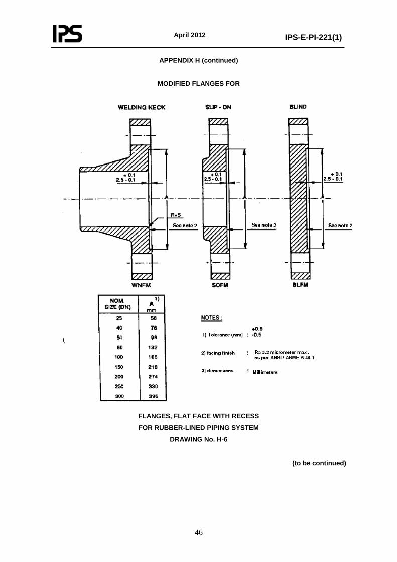
APPENDIX H (continued)
MODIFIED FLANGES FOR
FLANGES, FLAT FACE WITH RECESS
FOR RUBBER-LINED PIPING SYSTEM
DRAWING No. H-6
(to be continued)
April 2012
IPS-E-PI-221(1)
47
APPENDIX H (continued)
TYPICAL DETAILS OF
RUBBER LINED FLANGES
DRAWING No. H-7
April 2012
IPS-E-PI-221(1)
48
APPENDIX I GENERAL REQUIREMENTS FOR CEMENT LINING
OF NEW PIPELINES I.1 SCOPE This technical specification gives the minimum requirements for the design, application, inspection, installation and testing of pipes from nominal size DN 100 (4 inch) up to and including nominal size DN 900 (36 inch) to be lined with cement mortar in the shop and the jointing of these lined pipes in situ, including the hand-applied lining of the field butt-joints. The in situ lining of piping systems, other than the above mentioned joints, is outside the scope of this specification. Internal cement lining of pipelines is usually required for carbon steel cooling water or fire-fighting water piping systems containing/carrying sea-water or brackisch water at ambient temperatures to prevent internal corrosion. These systems can be installed above ground as well as underground. If an above ground lined piping system is drained for a longer period, special precautions are required to prevent cracking of the lining due to extreme high or low temperatures, and temperature or humidity variations. The special precautions to be taken are outside the scope of this specification. I.2 CONTRACT STRATEGY I.2.1 Contractor Involvement The contractor shall prepare for the manufacturer a detailed specification. In addition detailed Drawings shall be prepared if the details are not covered by the Drawings. Forementioned documents shall be approved by the Principal. I.2.2 Selection of Cement Lining Contractor The manufacture selected shall be able to design and install complete systems, including the procurement of all required piping materials together with technical services related to the products. In addition the manufacturer shall be responsible for the proper application of the cement lining to the field-joints. The manufacturer shall have provided systems to at least one Group Operating Company or prequalification tests shall be performed in accordance with section I.8. In both cases the final selection is subject to the Principals approval. Damage to the lining may occur during the application of the shop painting, handling, transport and storage of the pipes. Therefore the manufacturer of the cement lining should also apply the shop-painting and/or wrapping to the outside of the pipe. I.3 DESIGN OF CEMENT LINED PIPING SYSTEMS I.3.1 General Pressure design of pipes and fittings shall be in accordance with ASME/ANSI B31.3. I.3.2 Service Condition In general the fluid to be conveyed through cement lined pipes is sea-water or brackish water at ambient temperatures. However, the contractor shall obtain from the Principal a chemical analysis of the fluid to be conveyed.
(to be continued)
April 2012
IPS-E-PI-221(1)
49
APPENDIX I (continued) The temperature of the fluid to be transported shall not exceed 45°C. The composition of the lining shall be determined taking into account the nature, operating temperature and velocity of the fluid to be handled. The composition of the lining shall be agreed with the Principal. The lining applied shall have a design life of minimum 25 years. I.3.3 Sizing Criteria The diameter of the cement lined piping systems shall be sized so that the maximum water-velocity inside the lined piping shall not exceed 3 meters per second. The minimum outside diameter for piping and fittings to be cement lined is DN 100 (4 inch). The maximum diameter shall be DN 900 (36 inch). The straight length of the pipes shall be between 6 and 13 meters. Where carrying capacity is of importance, calculations shall be made to determine the maximum friction and loss of waterhead. Unless an increased thickness has been specified, the recommended lining thickness after curing, shall be as follows:
Nominal pipe size,
Inches
Minimum lining thickness, mm
Tolerance in mm
4 6 8
10 12 14
16 up to 36
5.0 5.0 6.0 6.0 8.0 8.0
10.0
+3 +3 +3 +3 +3 +3 +3
I.3.4 Limitations on Pipe I.3.4.1 Wall thickness The wall thickness of pipe (schedule No.) shall be as per piping class No. AZ03 of IPS-E-PI-221/2. I.3.4.2 Tolerances Tolerances on dimensions of pipe ends shall be in accordance with API 5L (including the ends of fabricated fittings). I.3.5 Fittings, Flanges, Gaskets and Valves I.3.5.1 Fittings For the selection and overall dimensions of fabricated fittings see Drawings No. I-3 and I-4. For typical details of a set-on branch (for cement lined fittings) see Drawing No. I-7. For dimensions of sleeves see Drawing No. I-5. Factorymade butt welding fittings shall be in accordance with ASME/ANSI B16.9. All sleeve-Joint connections of the piping shall be prefabricated prior to installing the lining. All pipes, T-pieces, and other fittings shall be prepared with bevelled ends. When sleeve couplings shall be applied, for piping with a diameter of DN 600 (24 inch) or less, the pipes shall be prepared with one end plain and the other end with a sleeve coupling, externally welded to the pipe. T-pieces, valves and other fittings shall be prepared with sleeve couplings welded to both ends. In this case one of the straight pipes connected to the forementioned shall be provided without sleeves.
(to be continued)
April 2012
IPS-E-PI-221(1)
50
APPENDIX I (continued) Joints for piping with diameters DN 650 (26 inch) up to and including DN 900 (36 inch) shall be butt-welded. For shop-welding, welding procedures and welders shall be qualified in accordance with ASME Section IX. The procedures shall be submitted to the Principal for approval. I.3.5.2 Flanges All flanges shall be class 150, raised face, except those connected to flat face flanges of glass-fibre reinforced epoxy or equipment with cast iron flanges etc. In these cases a suitable matching flange should be used. Slip-on flanges should be installed in pipe sizes from DN 100 through DN 600. For pipe sizes DN 650 and larger welding neck flanges shall be used. Flanges from DN 100 through DN 600 shall be in accordance with ASME/ANSI B16.5 and flanges from DN 650 and larger shall be in accordance with MSS SP-44. Flange facing shall be smooth finish between Ra 3.2 and 6.3 micrometers. For flanged ends (slip-on) for cement-lined pipe and fittings see Drawing No. I-6. For shop-welding, refer I.3.5.1. I.3.5.3 Gaskets For design pressures up to and including 10 bar ga the gaskets shall be 3 mm thick, reinforced chloroprene rubber with a Shore A hardness of 70. For design pressures above 10 bar ga, CAF gaskets 3 mm thick shall be used. The inside diameter of the gasket shall be equal to the inside diameter of the cement lining. Note that on some pipe-to-pipe valve (e.g. butterfly) connections the cement lining I.D. is tapered to equal the pipe I.D. at the gasket position to prevent possible inferference of the valve disc with the cement lining (see Drawing No. I-2). I.3.5.4 Valves The valves shall be as per piping class No. AZ03 of IPS-E-PI-221/2. I.3.6 Selection of Materials I.3.6.1 Pipes Seamless : DN 100 through DN 400-API 5L GR.B - 1) 2) 3) 4) Welded : DN 450 through DN 900-API 5L GR.B - 1) 2) 4) 5)
(Submerged-arc weld) Notes:
1) Carbon content 0.23% max. 2) Rimming steel not permissible 3) Non-expanded pipe 4) Jointers not acceptable 5) Cold expansion is acceptable up to a maximum of 1.70%
(to be continued)
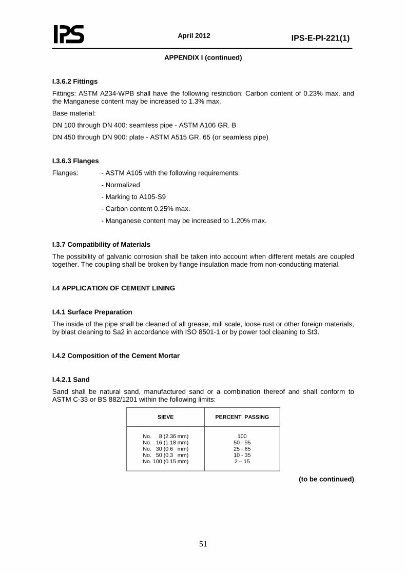
April 2012
IPS-E-PI-221(1)
51
APPENDIX I (continued)
I.3.6.2 Fittings
Fittings: ASTM A234-WPB shall have the following restriction: Carbon content of 0.23% max. and the Manganese content may be increased to 1.3% max.
Base material:
DN 100 through DN 400: seamless pipe - ASTM A106 GR. B
DN 450 through DN 900: plate - ASTM A515 GR. 65 (or seamless pipe)
I.3.6.3 Flanges
Flanges: - ASTM A105 with the following requirements:
- Normalized
- Marking to A105-S9
- Carbon content 0.25% max.
- Manganese content may be increased to 1.20% max.
I.3.7 Compatibility of Materials
The possibility of galvanic corrosion shall be taken into account when different metals are coupled together. The coupling shall be broken by flange insulation made from non-conducting material.
I.4 APPLICATION OF CEMENT LINING
I.4.1 Surface Preparation
The inside of the pipe shall be cleaned of all grease, mill scale, loose rust or other foreign materials, by blast cleaning to Sa2 in accordance with ISO 8501-1 or by power tool cleaning to St3.
I.4.2 Composition of the Cement Mortar
I.4.2.1 Sand
Sand shall be natural sand, manufactured sand or a combination thereof and shall conform to ASTM C-33 or BS 882/1201 within the following limits:
SIEVE
PERCENT PASSING
No. 8 (2.36 mm) No. 16 (1.18 mm) No. 30 (0.6 mm) No. 50 (0.3 mm) No. 100 (0.15 mm)
100
50 - 95 25 - 65 10 - 35 2 – 15
(to be continued)
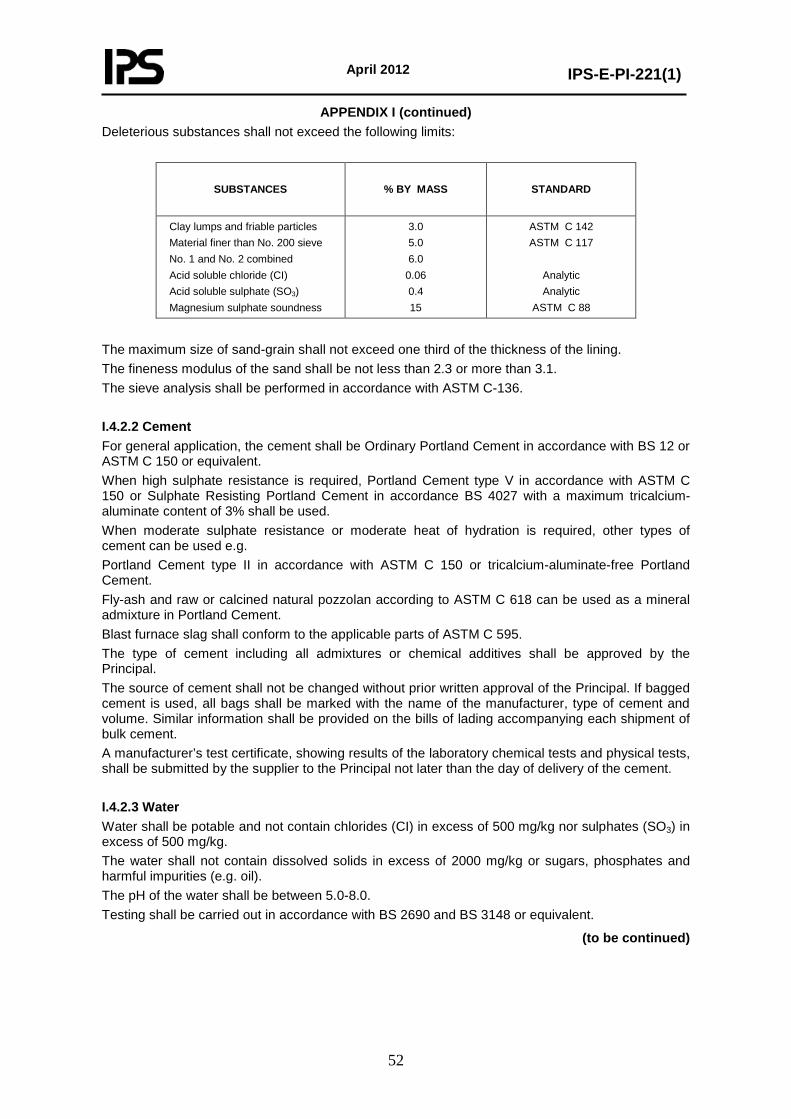
April 2012
IPS-E-PI-221(1)
52
APPENDIX I (continued) Deleterious substances shall not exceed the following limits:
SUBSTANCES
% BY MASS
STANDARD
Clay lumps and friable particles Material finer than No. 200 sieve No. 1 and No. 2 combined Acid soluble chloride (CI) Acid soluble sulphate (SO3) Magnesium sulphate soundness
3.0 5.0 6.0
0.06 0.4 15
ASTM C 142 ASTM C 117
Analytic Analytic
ASTM C 88
The maximum size of sand-grain shall not exceed one third of the thickness of the lining. The fineness modulus of the sand shall be not less than 2.3 or more than 3.1. The sieve analysis shall be performed in accordance with ASTM C-136. I.4.2.2 Cement For general application, the cement shall be Ordinary Portland Cement in accordance with BS 12 or ASTM C 150 or equivalent. When high sulphate resistance is required, Portland Cement type V in accordance with ASTM C 150 or Sulphate Resisting Portland Cement in accordance BS 4027 with a maximum tricalcium-aluminate content of 3% shall be used. When moderate sulphate resistance or moderate heat of hydration is required, other types of cement can be used e.g. Portland Cement type II in accordance with ASTM C 150 or tricalcium-aluminate-free Portland Cement. Fly-ash and raw or calcined natural pozzolan according to ASTM C 618 can be used as a mineral admixture in Portland Cement. Blast furnace slag shall conform to the applicable parts of ASTM C 595. The type of cement including all admixtures or chemical additives shall be approved by the Principal. The source of cement shall not be changed without prior written approval of the Principal. If bagged cement is used, all bags shall be marked with the name of the manufacturer, type of cement and volume. Similar information shall be provided on the bills of lading accompanying each shipment of bulk cement. A manufacturer’s test certificate, showing results of the laboratory chemical tests and physical tests, shall be submitted by the supplier to the Principal not later than the day of delivery of the cement. I.4.2.3 Water Water shall be potable and not contain chlorides (CI) in excess of 500 mg/kg nor sulphates (SO3) in excess of 500 mg/kg. The water shall not contain dissolved solids in excess of 2000 mg/kg or sugars, phosphates and harmful impurities (e.g. oil). The pH of the water shall be between 5.0-8.0. Testing shall be carried out in accordance with BS 2690 and BS 3148 or equivalent.
(to be continued)
April 2012
IPS-E-PI-221(1)
53
APPENDIX I (continued) I.4.2.4 Cement mortar mix Unless otherwise agreed the cement/sand ratio and the water/cement ratio shall be as follows:
- The cement/sand ratio shall be one part by weight of cement and one and a half part by weight of dry sand (1:1.5) for linings not exceeding 6 mm. - For linings with a thickness > 6 mm, the cement/sand ratio shall be 1:1 (parts by weight). - The water/cement ratio shall be between 0.3 and 0.4.
I.4.3 Installation of Shop Cement Lining I.4.3.1 General Straight sections of pipes, diameters from DN 100 (4 inch) up to and including DN 900 (36 inch), length 6 to 13 meters, shall be lined with the spinning method. The interior surface shall be smooth, straight and true and the sand/cement particles shall be equally distributed throughout the lining thickness, after completion of the lining process. I.4.3.2 Spinning method The lining shall be applied by a spinning machine specifically designed and built for the purpose of applying cement mortar linings to the interior of steel pipe by means of centrifugal forces and rotation of the pipe. To prevent distortion or vibration during spinning, each section of pipe shall if required, be braced with external or internal supports. The entire quantity of mortar required for the lining of one section of pipe shall be placed without interruption. The pipe shall be rotated slowly until the mortar has been equally distributed along the inside periphery of the pipe. Thereafter the rotation speed shall be increased to produce a dense lining with a smooth surface and a minimum of shrinkage. Provisions shall be made for removal of surplus of water. I.4.3.3 Bends and fittings Bends and fittings which cannot be machine lined in accordance with (I.4.3.2) may receive a hand-applied mortar lining. Hand-applied mortar shall have a uniform surface. Cement mortar for hand work shall be of the same consistency and material as the mortar for machine method. Surfaces to be lined shall be cleaned in accordance with (I.4.1) and damped with water immediately prior to placing the hand-applied mortar. Steel finishing trowels shall be used for the hand application of cement mortar. I.4.4 Curing I.4.4.1 General After application of the lining, the pipe and/or fittings shall be sealed with plastic caps and left to cure in situ, or they may be transferred carefully to a curing yard. The curing area shall be sheltered, so that lined pipes and fittings are protected from harmful climatic conditions (e.g. exposure to direct sun, frost, etc.). Within 24 hours after application of the cement lining the bores shall be inspected and water added to aid curing if required. After the inspection, the ends of the pipes and fittings shall be re-capped with the plastic caps. These covers shall not be removed within 14 days after cement lining in order to protect the lining form drying out.
(to be continued)
April 2012
IPS-E-PI-221(1)
54
APPENDIX I (continued) Pipes or fittings shall not be removed from the curing yard until the curing procedure is completed and the mortar has reached its specified strength. Water to be used for curing shall be in accordance with (I.4.2.3). I.4.4.2 Normal curing The lining shall be protected form drying out as specified above for the whole period of the hardening process of the mortar in order to minimize shrinkage cracks. The minimum period of hardening shall be 28 days. I.4.4.3 Water curing The lining shall be kept totally submerged for the total period of the hardening process of the mortar in order to minimize shrinkage cracks. The minimum period of hardening shall be 4 days. I.4.4.4 Steam curing Steam curing shall only be applied if required and approved by the Principal. Recording thermometers shall be installed. I.4.4.5 Membrane curing Membrane curing by application of any moisture-retaining liquid is not permitted. I.4.5 Lining Repair Dummy, spalled and excessively cracked areas, etc. in fully accessible pipes shall be removed and repaired by hand to the required thickness of the lining. Cracks with a width less than 0.8 mm can be left, providing they will not impair the stability of the lining, as the selfhealing effect will set them tight as soon as the pipes are in operation. Cracks with a width greater than 0.8 mm can be washed in by means of soft brush with a liquid sand/cement mixture consisting of one part cement and one part fine sand (0.1 mm). The mixture should be liquid similar to heavy paint. Larger local damages, other than cracks, shall be repaired by removing all loose particles, old mortar, grease and dirt by brushing with a stiff/wire brush. All traces of oil and grease shall be removed with a suitable de-greasing agent. The sides of the existing cement lining shall be primed with a multi-purpose adhesive, based on synthetic resin. The damaged area shall be filled with a ready mixed mortar. The repaired lining shall be finished by means of a trowel or a spatula and brushed flush with the original cement, it shall be kept moist for at least three days. Minor damage can be repaired by means of a multi-purpose adhesive. I.5 COATING OF CEMENT-LINED PIPES The faces of all flanges to be used in cement lined piping systems shall be coated with Shell Ensis Fluid SDC, after which they shall be provided with protective covers. The shop-painting of the outside surface of the pipe, shall be carried out after installing and curing of the cement lining, while the wrapping of the outside surface of the pipe (if required) shall be done before the installation and curing of the lining.
(to be continued)
April 2012
IPS-E-PI-221(1)
55
APPENDIX I (continued) I.6 HANDLING OF CEMENT-LINED PIPE Lined pipes and fittings shall be handled carefully to avoid internal damage to the cement lining. The end caps shall be kept in place during transport and storage in order to prevent dust, dirt, foreign matter etc. entering the pipe. For loading and unloading of very heavy pipes, it is recommended to use slings with cushion pads or a suitable forkarrangement placed at the centre of the joints. Hooks or other devices which insert into the ends of the pipe shall not be used. A flat-bed trailer provides the best support for the lined pipes during transport. During loading or unloading lined pipes shall not be dropped onto or off the transporting vehicle. To prevent bending of the pipes which can cause damage to the lining, supports shall be used during storage and shipping. The distance between the supports shall not exceed 3 m. Pipes shall be stored in supported tiers. The height of the tiers depends on the diameter of the pipes and shall not be more than 10 pipes for diameters < DN 150 (6 inch), 6 pipes for diameters between DN 200 to DN 400 (8 inch to 16 inch), 4 pipes for diameters between DN 500 to DN 900 (20 inch to 36 inch). I.7 FIELD-JOINTING I.7.1 General The pipes and fittings shall be assembled in situ by means of field welds or flanged connections. The field welds shall be butt-joints for pipe diameters of 26 inch and above and sleeve-joints for diameters below 26 inch. However, buttjoints shall be internally lined in situ. The Contractor and Principal shall agree upon the type of multi-purpose adhesive and the ready mixed mortar to be used for the assembling of the pipes. Alternative methods for field jointing of cement lined pipes and fittings (for instance with impregnated gaskets etc.) are subject to approval of the Principal. I.7.2 Butt-Jointing The bevelled ends of the cement lined pipes shall be thoroughly cleaned, see (I.4.1), and all loose particles of the cement lining shall be removed over 20 mm at both ends of the pipe, i.e. 20 mm at either side of the joint, see also Fig. 4 of Drawing No. I-1. After the welding (see section I.7.5) has been completed, a hand-applied mortar shall be used to finish the cement lining at the inside surface of the steel pipe at the location of field weld, see Fig. 5 of Drawing No. I-1. Unless another method has been agreed upon, the sides of the existing cement lining shall be sealed with a priming coat consisting of one part of a multi-purpose adhesive, based on synthetic resin (e.g. Conline "CEBOND", X-PANDO COMPOUND No. 2, SINMAST 121 or approved, equivalent bonding agent) and one part of potable water. After this priming coat has become tacky (20-30 minutes), the ready mixed mortar shall be applied. The application of the adhesive and ready mixed mortar shall be in accordance with manufacturer’s specifications. The hand applied mortar shall be finished by means of a trowel or spatula and shall be brushed flush after which a curing compound shall be applied. Pressure testing of a pipe section with site applied cement lining shall be delayed until 28 days after application or until such time that the minimum compression strength has been reached (this will require an earlier compressive strength test in addition to the 28 day test, I.9.1.6).
(to be continued)
April 2012
IPS-E-PI-221(1)
56
APPENDIX I (continued) I.7.3 Sleeve-Jointing The free access-length of the female part shall be determined prior to the jointing and shall be marked on the male part over the full circumference, see Fig. 2A and 2B of Drawing No. I-1. The cut-end of the pipe inside the sleeve coupling shall be thoroughly cleaned, dry and free of dust and shall be provided with a concrete glue. This type of glue shall be based on a two component solvent free epoxy-resin (e.g. "SINMAST UW" or approved equivalent) suitable for application on moist mortar surfaces. Before installation of the male pipe end part, the concrete glue shall be tapered with a minimum thickness at the cement lining edge of 3 mm and with an angle of 75°, see also Fig. 2 of Drawing No. I-1. Immediately after the application of the concrete glue, the male part shall be carefully pulled into the female part, without distorting the alignment (i.e. center-line) of the pipe and shall be tack-welded in accordance with section (I.7.5). I.7.4 Cutting to Size in Situ When cutting in situ is unavoidable, this shall be carried out at the required position by means of cutting-disk of 3 mm. Flame cutting is not allowed. The end of the steel pipe shall be cut perpendicular to the pipe and bevelled (if required) depending on the type of the field-joint. For a sleeve-joint, the cut pipe end shall be used as the female part. For a buttweld joint the cement lining shall be cut over a length of at least 20 m/m at the end of the pipe. In both cases the cement lining shall be cut perpendicular to the pipe. Typical details of the pipe ends are shown on Drawing No. I-1. I.7.5 Field Welding The pipes shall be tack-welded in three equidistant positions. The pipe shall be joined by the shielded metal arc welding process. The arc shall not come in direct contact with the cement lining or seal material. Starts and stops shall be staggered so as not to start or stop more than once in the same place. Welding slag shall be cleaned from all weld passed. Welding procedures and welders shall be qualified in accordance with ASME Section IX, the procedures shall be submitted to the Principal for approval. Welding materials used shall be in accordance with the current list of approved welding consumables published by Lloyds Register of Shipping, Controlas or other internationally acknowledged bodies. I.8 QUALITY CONTROL I.8.1 General Before the start of the actual cement lining production the manufacturer shall make arrangements to execute line-up tests in order to demonstrate the suitability of the equipment for an uninterrupted production process. All required materials shall be supplied by the manufacturer. The testing shall reflect the actual application conditions. The entire process of applying cement mortar lining, at the manufacturer’s works and at the construction site, shall be subject to continuous inspection by a QC inspector appointed by the contractor, but such inspections shall not relieve the manufacturer of his responsibility to furnish material and perform the work in accordance with this specification.
(to be continued)
April 2012
IPS-E-PI-221(1)
57
APPENDIX I (continued) I.8.2 Procedure Qualification Test Prior to the installation of the shop cement lining, or in case of any variation in the process or composition of the mortar or change in any components the manufacturer shall perform procedure tests to demonstrate that he is able to produce a lining system in accordance with the design requirements. The constituents, mortar and finished pipe shall be tested, the samples shall be taken from one of the first finished test pipes or fittings, and testing shall be carried out as indicated below:
Individual constituents of the mix - cement/admixture - sand - water
Cement mortar test specimen - density - compressive strength - flexural tensile strength - water absorbtion
Finished product - visual inspection
The acceptance criteria for the tests shall be in accordance with section (I.9). Successful tests qualifies the procedure for the installation of the actual lining. A record shall be made of the complete test procedure, including:
- details of test piece, - batch identification of cement mortar. - test data and results. - acceptance by principal’s inspector.
I.8.3 Quality Control During Shop Application During preparation of the cement mortar and subsequent application, a regular production sampling program shall be established and maintained. A logbook shall be kept showing the portion of the completed lining which is represented by the sample and all information regarding the sample preparation and the operating parameters at the time of sample collection such as ambient temperatures, water content, cement/sand ratio, mixing times. Preparation of the samples shall be witnessed by the QC inspector. Immediately after the final spin an inspection of the cement lining shall be carried out by looking through the pipe from each end, using a strong light. Defects in lining including but not restricted to sand pockets, voids, sags, oversanded areas, blisters, excessively cracked and dummy areas, and unsatisfactory thin spots shall be removed before the initial set of the mortar. Defective areas encompassing the full diameter of the pipe shall be repaired by machine. Small defects in pipes > DN 600 (24 inch) shall be repaired by hand to the full required thickness of the cement lining. In pipes less than DN 600 (24 inch), defective lining shall be removed before the initial set of the mortar. Defective linings rejected after initial set shall be replaced or repaired by the most practical method to be determined by the manufacturer in accordance with a procedure approved by the Principal.
(to be continued)
April 2012
IPS-E-PI-221(1)
58
APPENDIX I (continued) Most cracking occurs when the lining is allowed to dry out during curing, transportation and storage. The inspector shall ensure that the lining is still moist after inspection and that air-tight end caps are placed and maintained on the pipe. I.8.4 Quality Control During Field-Jointing Before assembling the pipes and fittings shall be inspected for possible cracks and damage. If required any cracks and damage shall be repaired prior to the assembling of the piping system see (I.4.5). The cement shall be the same as applied for the shop cement lining. Both sand and cement and quality shall meet the requirements as described in section (I.4.2.1) and (I.4.2.2). The lengths of pipe shall be butted together and checked for alignment and good contact of the cement lining and pipe ends. A ready mixed mortar shall be used for the butt-joints and to repair linings of butt-joints. It is recommended to inspect the piping system 8 days after completion of the cement lining. I.8.5 Production Tests Production testing shall be performed during manufacturing of the pipe lining and tests and inspection shall be carried out in accordance with the table below. All test results shall be reported and submitted to the Principal.
Test or inspection
Frequency
cement/admixture sand/additives water/cement ratio mixing ratio/times density compressive strength flexural strength ambient temperature visual inspection lining thickness pipe and fitting ends surface condition lining structure
once per batch delivered once per week twice a day twice a day twice a day twice a day twice a day once a day continuously 20% of pipes and fittings each pipe and fitting each pipe and fitting once per week
The acceptance criteria for the tests shall be in accordance with section (I.9). I.9 TESTS AND INSPECTION CRITERIA I.9.1 General All bare pipes shall be inspected before cleaning and lining. The surface on which the cement lining is to be installed shall be free from all grease, mill scale, loose rust or other foreign materials prior to the installation of the cement lining. Test samples of the cement lining mortar shall be prepared by the manufacturer. Each sample shall be clearly marked with the contractor’s code numbers for that day/shift/crew and for sequence of production. The manufacturer shall be responsible for regular transport of samples to an independent qualified laboratory, subject to Principal’s approval. If samples or completed lining do not meet the specified criteria, the installed cement lining represented by the failing sample(s), shall be removed and replaced. Completed lining not meeting the specified criteria under I.9.1.10 / I.9.1.11 / I.9.1.12 / I.9.1.13 shall be rejected.
(to be continued)
April 2012
IPS-E-PI-221(1)
59
APPENDIX I (continued)
I.9.1.1 Sand
For test criteria refer (I.4.2.1) of this specification.
I.9.1.2 Cement
For test criteria refer (I.4.2.2) of this specification.
I.9.1.3 Water
For test criteria refer (I.4.2.3) of this specification.
I.9.1.4 Water/Cement ratio
The Water/Cement ratio determined in accordance with DIN 1048, "Drying to constant weight", shall be between 0.30 and 0.40.
I.9.1.5 Mixing ratio
The dry-mix of lining materials shall not contain less than 40% nor more than 50% of cement by weight.
I.9.1.6 Compressive strength
The compressive strength after a curing period of 28 days, tested in accordance with ASTM C 349, shall not be less than 55 N/mm2.
I.9.1.7 Flexural strength
The flexural strength after a curing period of 28 days, tested in accordance with ASTM C 348, shall not be less than 6.5 N/mm2.
I.9.1.8 Density
The density, measured in a saturated, surface dry condition, shall not be less than 2160 kg/m3.
I.9.1.9 Water absorbtion
The water absorbtion of the sample, tested in accordance with ASTM C 642 shall not exceed 10%.
I.9.1.10 Lining thickness
The thickness of the lining shall be measured on the vertical and horizontal diameters of the cut faces at both pipe ends, that is at clock positions 3, 6, 9 and 12, by direct measurement or by means of suitable electric instrument e.g. a covermeter, calibrated before use. The values of lining thickness shall be given with an accuracy of 0.10 mm. For tolerances of lining thicknesses see (I.3.3) of this specification. (to be continued)
April 2012
IPS-E-PI-221(1)
60
APPENDIX I (continued) I.9.1.11 Pipe and fitting ends Pipe and fitting ends of pipes and fittings with a diameter of 26 inch and above assembled in situ by means of field welding shall have the cement lining removed over a length of 20 mm at either side of the pipe. The ends of the lined pipes are considered to be defective if the lining end is:
a) not located as specified, b) not perpendicular to the longitudinal axis of the pipe, c) not square, d) chipped or cracked, e) separated from the steel pipe surface, f) not to the specified thickness.
In addition to the above the welding bevel shall be free of cement. I.9.1.12 Surface condition The surface condition of the finished cement lining shall be smooth and even, not be flattened at individual spots, not have loose sand, not have dummy, spalled or excessively cracked areas or show waves or grooves. Single waves or grooves are acceptable providing the minimum specified lining thickness is maintained. However, the maximum peak to trough height shall not exceed 1.0 mm. Aggregate grains may only protrude at the surface sporadically. Hairline cracks and sporadically occurring surface cracks up to 0.8 mm are allowed. Voids, being a place in the pipe where the cement lining is not continuous, are not acceptable. Voids occur during the spinning process when the cement does not distribute evenly. Sags, appearing as large smooth lumps in the lining at the top of the pipe, are not acceptable. I.9.1.13 Lining structure The polished section of a cement lined pipe sample shall not have visible pores and the individual grains of the sand shall be surrounded on all sides with the cementing agent. I.10 FABRICATION REPORT After finishing the work as defined in the purchase order, the contractor shall provide a fabrication report with the following contents:
- project references such as: location, project number, piping system - bill of materials including lining - reference drawings and specifications - registration of date and time of application of all phases - registration of the produced samples and tests results - final inspection results - welding procedures used
This report shall also include certificates for the following materials: - piping, fittings, flanges, gaskets and valves, - welding consumables, - sand,
(to be continued)
April 2012
IPS-E-PI-221(1)
61
APPENDIX I (continued)
Cement mill test certificates shall be provided for each shipment of:
- cement
- admixtures and additives,
- adhesives, concrete glue and ready-mixed mortar.
I.11 GUARANTEE
If an inspection by the Principal of the cement lining work within a period of five year after final completion and acceptance of the contract work gives evidence of defective materials or workmanship as defined in this specification, then the Principal may order such remedies as described in section (I.4.5) of this specification. The manufacturer shall perform the repairs at his own expence in a manner acceptable to the Principal.
(to be continued)
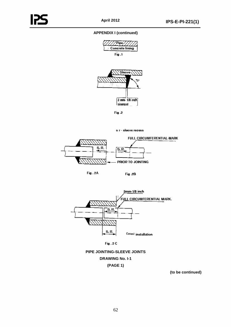
April 2012
IPS-E-PI-221(1)
62
APPENDIX I (continued)
PIPE JOINTING-SLEEVE JOINTS
DRAWING No. I-1
(PAGE 1)
(to be continued)
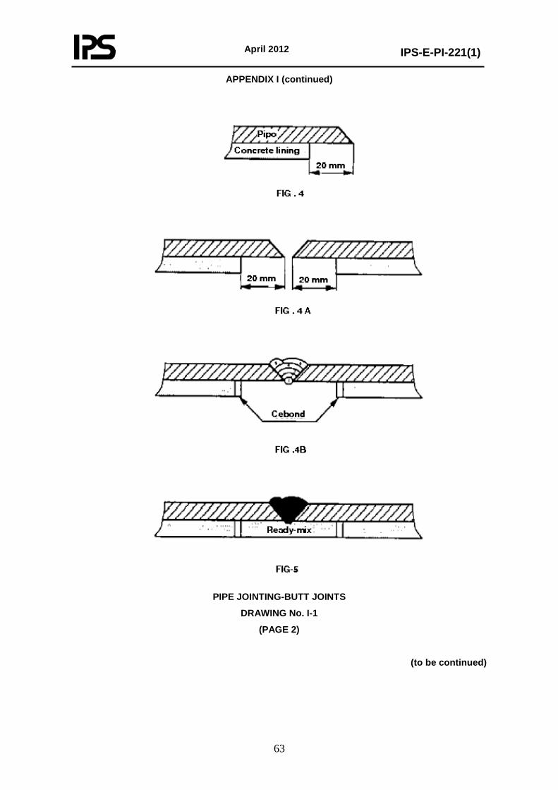
April 2012
IPS-E-PI-221(1)
63
APPENDIX I (continued)
PIPE JOINTING-BUTT JOINTS
DRAWING No. I-1
(PAGE 2)
(to be continued)
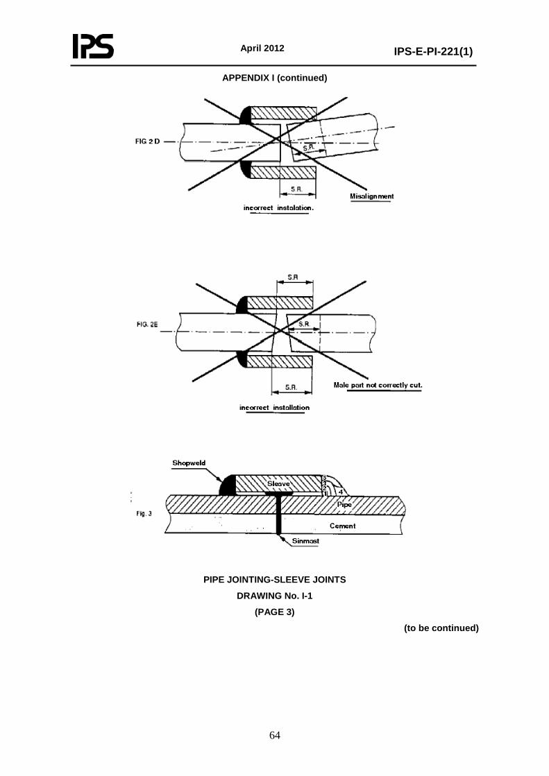
April 2012
IPS-E-PI-221(1)
64
APPENDIX I (continued)
PIPE JOINTING-SLEEVE JOINTS
DRAWING No. I-1
(PAGE 3)
(to be continued)
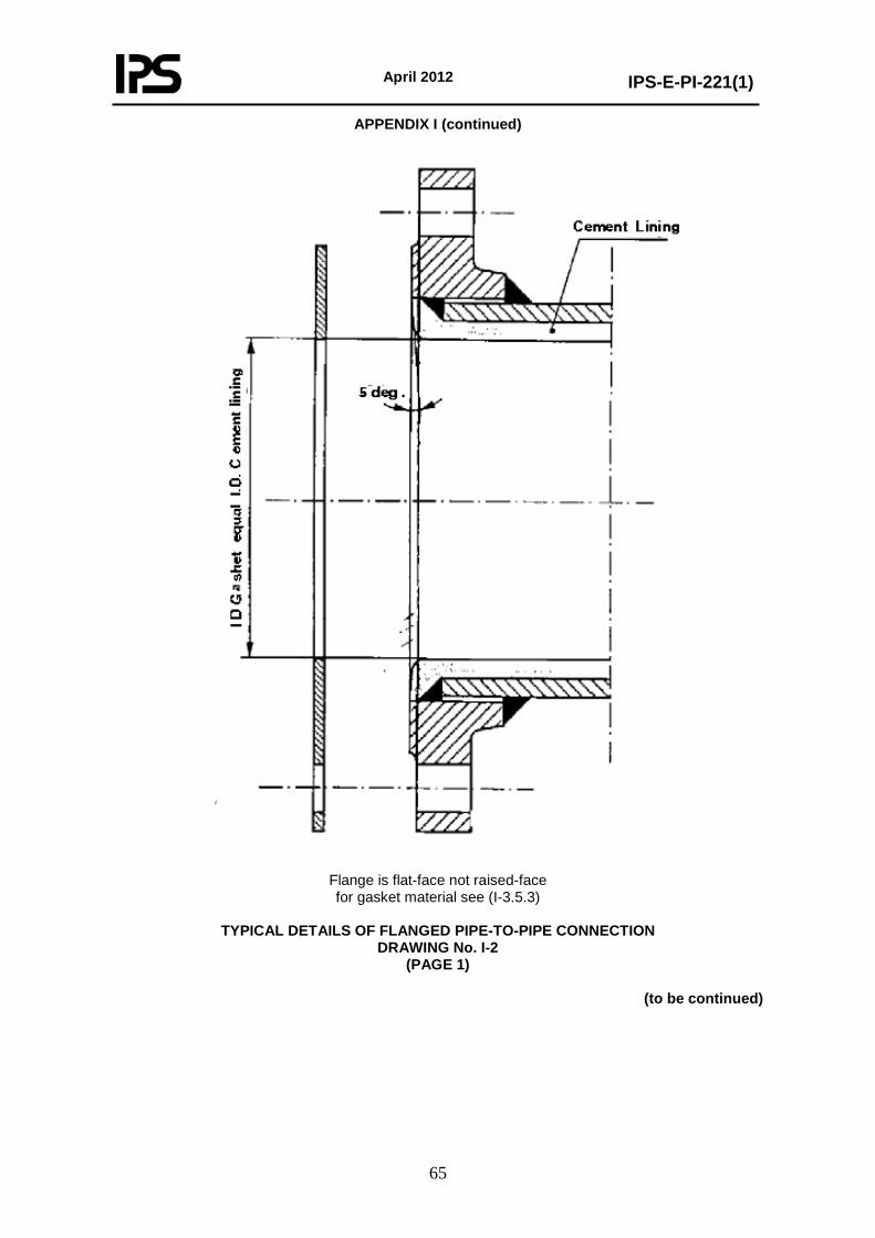
April 2012
IPS-E-PI-221(1)
65
APPENDIX I (continued)
Flange is flat-face not raised-face for gasket material see (I-3.5.3)
TYPICAL DETAILS OF FLANGED PIPE-TO-PIPE CONNECTION
DRAWING No. I-2 (PAGE 1)
(to be continued)
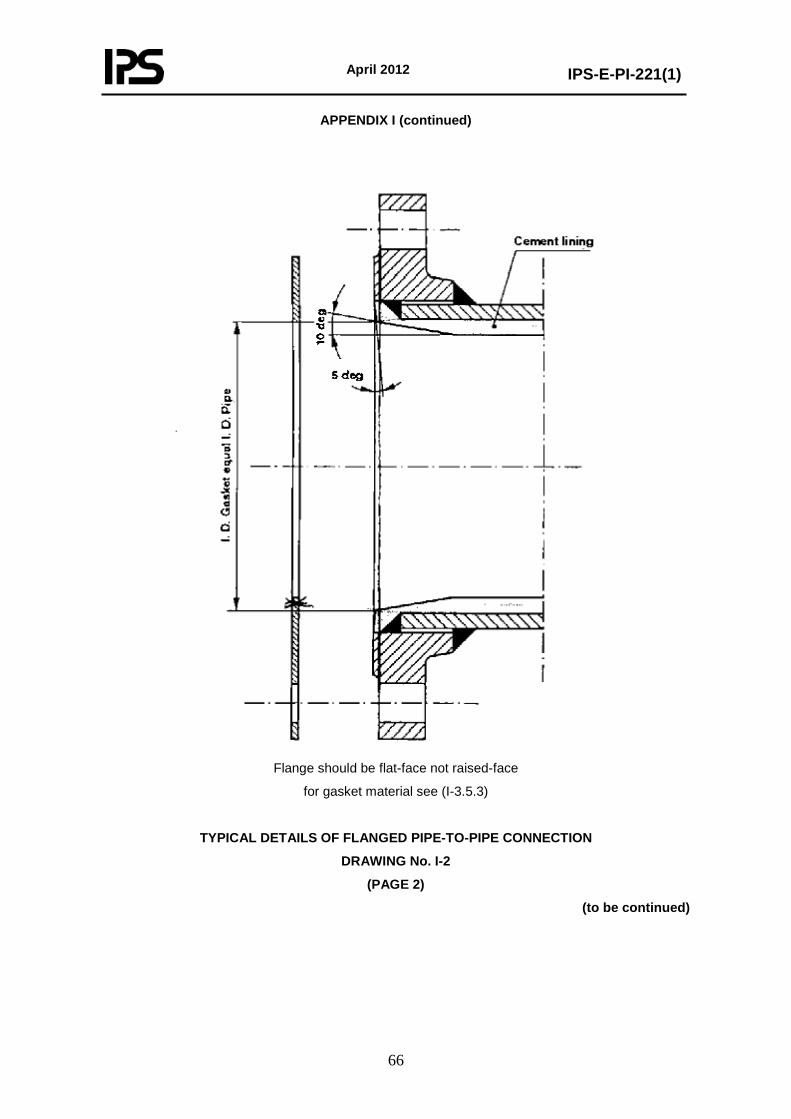
April 2012
IPS-E-PI-221(1)
66
APPENDIX I (continued)
Flange should be flat-face not raised-face
for gasket material see (I-3.5.3)
TYPICAL DETAILS OF FLANGED PIPE-TO-PIPE CONNECTION
DRAWING No. I-2
(PAGE 2)
(to be continued)
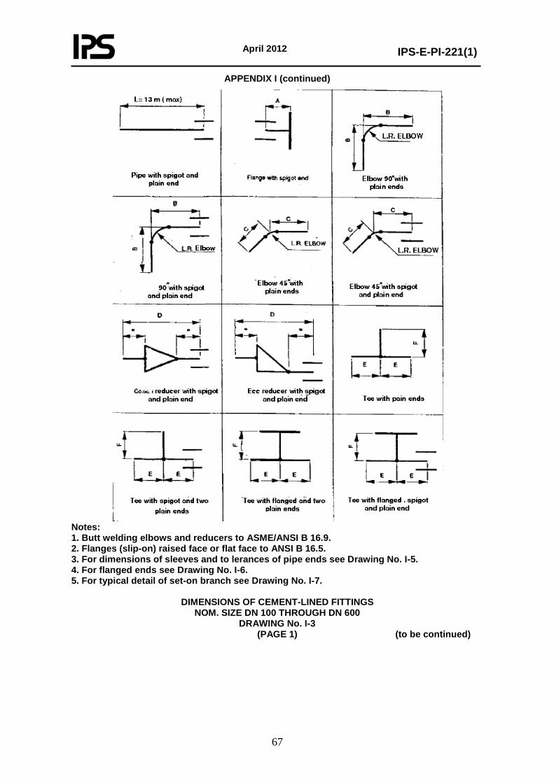
April 2012
IPS-E-PI-221(1)
67
APPENDIX I (continued)
Notes: 1. Butt welding elbows and reducers to ASME/ANSI B 16.9. 2. Flanges (slip-on) raised face or flat face to ANSI B 16.5. 3. For dimensions of sleeves and to lerances of pipe ends see Drawing No. I-5. 4. For flanged ends see Drawing No. I-6. 5. For typical detail of set-on branch see Drawing No. I-7.
DIMENSIONS OF CEMENT-LINED FITTINGS
NOM. SIZE DN 100 THROUGH DN 600 DRAWING No. I-3
(PAGE 1) (to be continued)
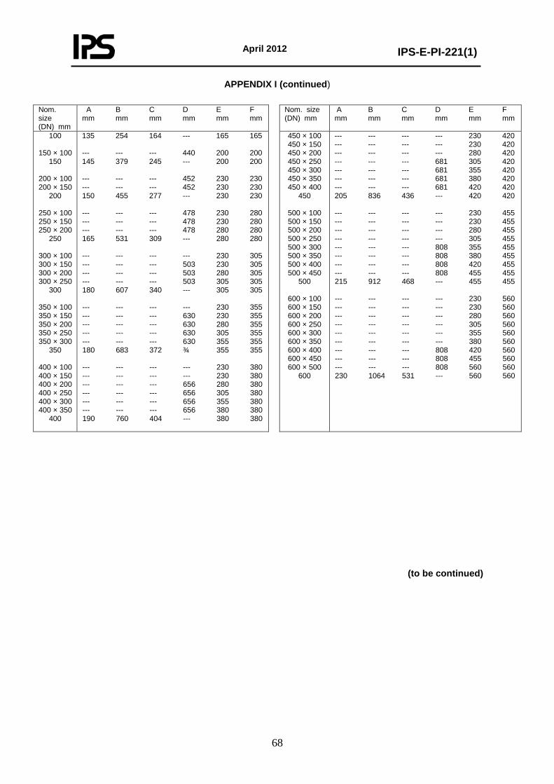
April 2012
IPS-E-PI-221(1)
68
APPENDIX I (continued)
Nom. size (DN) mm
A B C D E F mm mm mm mm mm mm
Nom. size (DN) mm
A B C D E F mm mm mm mm mm mm
100
150 × 100 150
200 × 100 200 × 150
200
250 × 100 250 × 150 250 × 200
250
300 × 100 300 × 150 300 × 200 300 × 250
300
350 × 100 350 × 150 350 × 200 350 × 250 350 × 300
350
400 × 100 400 × 150 400 × 200 400 × 250 400 × 300 400 × 350
400
135 254 164 --- 165 165 --- --- --- 440 200 200 145 379 245 --- 200 200 --- --- --- 452 230 230 --- --- --- 452 230 230 150 455 277 --- 230 230 --- --- --- 478 230 280 --- --- --- 478 230 280 --- --- --- 478 280 280 165 531 309 --- 280 280 --- --- --- --- 230 305 --- --- --- 503 230 305 --- --- --- 503 280 305 --- --- --- 503 305 305 180 607 340 --- 305 305 --- --- --- --- 230 355 --- --- --- 630 230 355 --- --- --- 630 280 355 --- --- --- 630 305 355 --- --- --- 630 355 355 180 683 372 ¾ 355 355 --- --- --- --- 230 380 --- --- --- --- 230 380 --- --- --- 656 280 380 --- --- --- 656 305 380 --- --- --- 656 355 380 --- --- --- 656 380 380 190 760 404 --- 380 380
450 × 100 450 × 150 450 × 200 450 × 250 450 × 300 450 × 350 450 × 400
450
500 × 100 500 × 150 500 × 200 500 × 250 500 × 300 500 × 350 500 × 400 500 × 450
500
600 × 100 600 × 150 600 × 200 600 × 250 600 × 300 600 × 350 600 × 400 600 × 450 600 × 500
600
--- --- --- --- 230 420 --- --- --- --- 230 420 --- --- --- --- 280 420 --- --- --- 681 305 420 --- --- --- 681 355 420 --- --- --- 681 380 420 --- --- --- 681 420 420 205 836 436 --- 420 420 --- --- --- --- 230 455 --- --- --- --- 230 455 --- --- --- --- 280 455 --- --- --- --- 305 455 --- --- --- 808 355 455 --- --- --- 808 380 455 --- --- --- 808 420 455 --- --- --- 808 455 455 215 912 468 --- 455 455 --- --- --- --- 230 560 --- --- --- --- 230 560 --- --- --- --- 280 560 --- --- --- --- 305 560 --- --- --- --- 355 560 --- --- --- --- 380 560 --- --- --- 808 420 560 --- --- --- 808 455 560 --- --- --- 808 560 560 230 1064 531 --- 560 560
(to be continued)
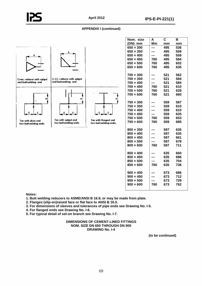
April 2012
IPS-E-PI-221(1)
69
APPENDIX I (continued)
Nom. size (DN) mm
A C B Mm mm mm
650 × 300 650 × 350 650 × 400 650 × 450 650 × 500 650 × 600 700 × 300 700 × 350 700 × 400 700 × 450 700 × 500 700 × 600 750 × 300 750 × 350 750 × 400 750 × 450 750 × 500 750 × 600 800 × 350 800 × 400 800 × 450 800 × 500 800 × 600 850 × 400 850 × 450 850 × 500 850 × 600 900 × 400 900 × 450 900 × 500 900 × 600
--- 495 536 --- 495 559 --- 495 559 760 495 584 760 495 602 760 495 635 --- 521 562 --- 521 584 --- 521 584 760 521 610 760 521 628 760 521 660 --- 559 587 --- 559 610 --- 559 610 --- 559 635 760 559 653 760 559 685 --- 597 635 --- 597 635 --- 597 661 --- 597 678 760 597 711 --- 635 660 --- 635 686 --- 635 704 760 635 736 --- 673 686 --- 673 712 --- 673 729 760 673 762
Notes: 1. Butt welding reducers to ASME/ANSI B 16.9, or may be made from plate. 2. Flanges (slip-on)raised face or flat face to ANSI B 16.5. 3. For dimensions of sleeves and tolerances of pipe ends see Drawing No. I-5. 4. For flanged ends see Drawing No. I-6. 5. For typical detail of set-on branch see Drawing No. I-7.
DIMENSIONS OF CEMENT-LINED FITTINGS
NOM. SIZE DN 650 THROUGH DN 900 DRAWING No. I-4
(to be continued)
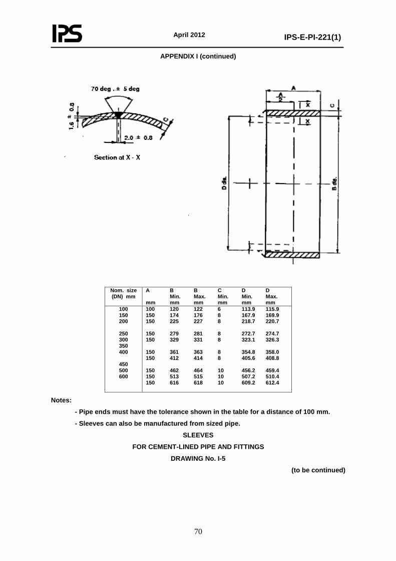
April 2012
IPS-E-PI-221(1)
70
APPENDIX I (continued)
Nom. size (DN) mm
A B B C D D Min. Max. Min. Min. Max. mm mm mm mm mm mm
100 150 200
250 300 350 400
450 500 600
100 120 122 6 113.9 115.9 150 174 176 8 167.9 169.9 150 225 227 8 218.7 220.7 150 279 281 8 272.7 274.7 150 329 331 8 323.1 326.3 150 361 363 8 354.8 358.0 150 412 414 8 405.6 408.8 150 462 464 10 456.2 459.4 150 513 515 10 507.2 510.4 150 616 618 10 609.2 612.4
Notes:
- Pipe ends must have the tolerance shown in the table for a distance of 100 mm.
- Sleeves can also be manufactured from sized pipe.
SLEEVES
FOR CEMENT-LINED PIPE AND FITTINGS
DRAWING No. I-5
(to be continued)
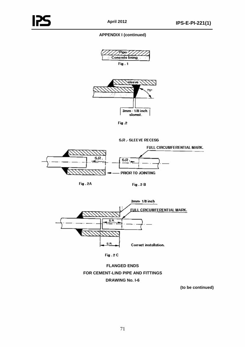
April 2012
IPS-E-PI-221(1)
71
APPENDIX I (continued)
FLANGED ENDS
FOR CEMENT-LIND PIPE AND FITTINGS
DRAWING No. I-6
(to be continued)
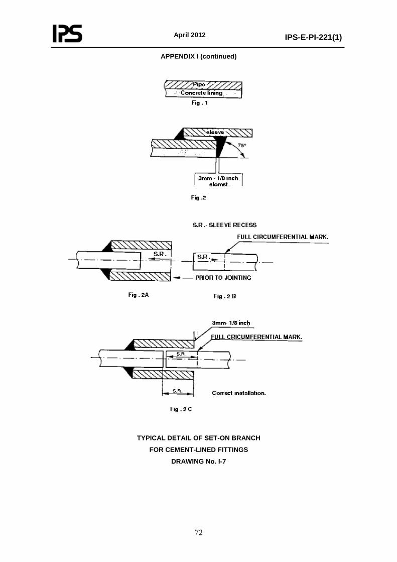
April 2012
IPS-E-PI-221(1)
72
APPENDIX I (continued)
TYPICAL DETAIL OF SET-ON BRANCH
FOR CEMENT-LINED FITTINGS
DRAWING No. I-7
April 2012
IPS-E-PI-221(1)
73
APPENDIX J
REQUIREMENTS FOR GLASS-FIBRE REINFORCED EPOXY
PIPES AND FITTINGS
J.1 INTRODUCTION
J.1.1 General
This specification covers the general requirements for the purchase, inspection and transportation of pipes, fittings and flanges made from glass-fibre reinforced epoxy (GRE) which belongs to glass-fibre reinforced thermosetting plastics (GRP).
Described are pipes, fittings and flanges made by the filament-winding, centrifugal casting or pressed-sheet moulding process.
Section J.5 describes the qualification testing program to which a manufacturer is subjected before his first delivery of GRP pipes and fittings.
Section J.6 describes the minimum number of production tests to be carried out for each subsequent delivery of GRP pipes and fittings by a manufacturer whose products have been qualified successfully.
Section J.7 describes the qualification testing procedure.
A number of requirements in this specification are comparable to those of API Specification 15 LR.
This specification does not cover high-pressure piping, as defined by API Spec. 15 LR (approx. 70 bar, (1000 PSI)), casing and tubing and reinforced plastic mortar piping. The Company shall be contacted for those applications.
The requirements of this specification shall be adhered to, except where national and/or local regulations exist in which specific requirements are more stringent.
The contractor shall determine by careful scrutiny which of these requirements are the more stringent and which combination of requirements will be acceptable as regards safety, economics and legal aspects.
In all cases the contractor shall inform the Company of any deviation from the requirements of this specification considered to be necessary to comply with national and/or local regulations. The Company may then negotiate with the authorities concerned with the object of obtaining agreement to follow this specification as closely as possible.
J.2 BASE MATERIALS
All base materials shall be new and unused, and shall be free from all contaminations and imperfections. The base materials, e.g. resins, glass-fibre reinforcing materials, pigments and other materials, when combined as a composite structure, shall produce pipe, fittings and flanges which meet the requirements of this specification. All base materials shall be specified in writing by the pipe manufacturer and certified by the raw materials supplier(s) per delivery.
J.2.1 Epoxy resins
Unless otherwise agreed, the pipes, fittings and flanges shall be made from a bisphenol A epichlorohydrin epoxy resin e.g. "EPIKOTE" 828 and an aromatic or cyclo-aliphatic amine-type curing agent. The manufacturer shall describe the type of resin and curing system chosen.
J.2.2 Glass-Fibre Reinforcement, Fillers and Pigments
Glass-fibre reinforcement for the reinforced wall shall be made of E-glass (i.e. low-alkali glass) meeting an internationally accepted standards such as BS 3691, BS 3396 and shall have a finish
April 2012
IPS-E-PI-221(1)
74
(coupling agent) which is compatible with the epoxy resin.
Fillers are not acceptable. Thixotropic additives added to the resin/curing agent mixture for viscosity control shall not exceed 2% by weight.
Pigments are only acceptable as long as they do not affect the performance of the components as defined in section (J.5) or if agreed with the Company in order to fulfil special application requirements.
J.2.3 Lining Materials
Unless otherwise agreed (J.3.1), flange surfaces and all pipes and fittings which are to be exposed to the fluid, shall have a smooth uniform resin-rich lining consisting of:
- a surfacing mat (tissue) or a veil, which may be either a C-glass (i.e. chemical-resistant glass) or a synthetic fibre, e.g. linear polyester fibres of polyacrylonitrile fibres;
- the same resin which is used for the fabrication of the pipe, fitting or flange.
J.2.4 Adhesives
Adhesive for adhesive-bonded connections shall be of an epoxy type, formulated to be resistant to the product to be conveyed, and for the service temperatures and pressures. It shall be of the type and quality regularly supplied by the pipe manufacturer for the duty intended, and as used for the qualification test (J.5.3.1) and shall have a proven record of good service.
The adhesives shall be provided in a kit containing at least epoxy resin and curing agent (separately in the recommended proportions) and mixing stick, joint cleaner, sandpaper and brush, together with instructions.
The adhesive kit shall have been date stamped at the time of the packaging and shall indicate the required storage conditions and date of expiration of shelf life.
The adhesive kit shelf life at 40°C shall not be less than six months from the date of shipment or 12 months from the date of production.
J.2.5 Rubber Sealing Rings
The sealing rings for the spigot and socket connections shall be made of a rubber type resistant to the product to be conveyed and for the service temperatures and pressures. The manufacturer shall state the type of rubber, providing evidence for its suitability in the proposed application.
J.2.6 Fixation Rod
The fixation rod for thrust-resistant spigot and socket connections with rubber sealing rings shall be made of a flexible thermoplastic material, resistant to the particular service conditions, such as temperature, surrounding environment, ultra-violet exposure etc. The manufacturer shall state the type of thermoplastic material, providing evidence for its suitability in the proposed application.
J.3 DESIGN AND DIMENSIONS
J.3.1 General
The manufacturer shall submit a piping stress analysis based on data for his specific brand and in accordance with ANSI/ASME B 31.3.
The components shall also be designed and manufactured to ANSI/ASME B 31.3.
If the influence of chemicals is to be taken into account, the manufacturer should state the maximum allowable operating conditions for continuous chemical service.
April 2012
IPS-E-PI-221(1)
75
The Company shall specify those applications where the presence of a lining is not mandatory, as in cases where less severe chemical resistance is required or for electrically conductive piping.
The manufacturer shall provide proper installation instructions and, if requested by the Company, adequate supervision at all stages of installation.
J.3.2 Dimensions
J.3.2.1 Pipes
Diameter
The pipe standard for filament-wound pipe may be based on either the inside diameter (Type A) or the outside diameter (Type B). Standard diameters for both types of pipes are given in Table J-1.
Centrifugally cast pipe is based on the outside diameter (Type B).
The inside diameter (Di) of type A1 pipes is equal to the nominal diameter.
The A2 and B1 series are based on a commercial need for pipes with the outside diameters equal to those of pipes made from other materials, e.g. cast iron and steel so as to enable joints to be made to existing pipes without special jointing adapters.
The dimensions of the B1 series are equal to those of Spec. 15 LR.
The B2 series have their outside diameter (Do) related to the nominal diameter (DN) by the equation Do = 1.02 DN + 4 mm.
Wall thickness
The reinforced wall thickness of the pipe shall be sufficient to withstand the temperatures, pressures and service conditions of the particular application. It shall be at least 1.8 mm.
Liner/Top coat
If a lining is specified, its thickness for filament-wound pipe shall be at least 0.5 mm. For centrifugally cast pipe the thickness of this lining shall be at least 1 mm. Pressed-sheet moulding compound (SMC) fittings have no liner but a press skin which shall be at least 0.2 mm thick.
All piping shall have a smooth resin rich top coat.
Ovality
The difference between the largest and smallest diameter (ovality) in each cross section, shall be not more than 0.007 Di (Type A) or 0.007 Do (Type B).
Ends
The pipe shall be supplied with plain ends, with shaved ends, with spigot ends, or with one spigot end and one (integral) socket end or with flanged ends as stated by the Company.
If pipe is to be furnished with threaded ends, threading shall be to API Std. 5B, unless otherwise agreed.
J.3.2.2 Fittings
Fittings shall be supplied with plain ends, spigot ends, integral socket ends, threaded adaptors or flanges as stated by the Company.
April 2012
IPS-E-PI-221(1)
76
The reinforced wall thickness of the fittings shall be sufficient to withstand the temperatures, pressures and service conditions of the particular application. It shall be at least 2.2 mm.
The difference between the largest and smallest measured inside diameter (ovality) shall not be more than 0.007 Di (Type A) or 0.007 Do (Type B).
J.3.2.3 Flanges
The outside diameter and drilling template of flanges shall be in accordance with ANSI B 16.5 class 150. The flange face shall be flat-type.
J.3.3 Prefabricated Piping Systems
Prefabricated piping systems may have adhesive-bonded socket/ spigot connections or hand-laminated butt and strap joints or integral spigots and/or sockets for connections with rubber sealing rings.
The surfaces without a liner at adhesive-bonded connections exposed to the product shall be covered by the adhesive.
The butt and strap joints shall be laminated over a length of at least the pipe diameter on the outside, and if the diameter allows, also on the inside.
All machined or cut surfaces, except the spigot ends, shall receive a coat of resin type, formulated to be resistant to the product to be conveyed and for use at the service temperatures and pressures.
J.4 FABRICATION
Unless otherwise agreed by the Company, the following fabrication/construction methods shall be adhered to.
Filament-wound pipe
Filament-wound pipe shall be manufactured by winding resin-impregnated continuous fibrous glass strand roving or woven glass roving tape on to the outside of a mandrel in a predetermined pattern under controlled tension.
Centrifugal cast pipe
Centrifugal cast pipe shall be manufactured by applying resin and reinforcement to the inside of a mould that is rotated and heated, subsequently polymerizing the resin system.
Fittings and flanges
Fittings shall be of a filament-wound construction. Flanges shall be of a filament-wound construction or a pressed-sheet moulded compound (SMC) construction. In the latter case the length of the reinforcing fibres shall be at least 12 mm. The application of fittings and flanges of another design shall be specifically agreed upon between Company and manufacturer.
J.5 TECHNICAL REQUIREMENTS
J.5.1 General
Pipes and fittings purchased to this specification shall meet the requirements as stated in (J.2), (J.3) and (J.4) and shall further be in accordance with the technical requirements specified in this section.
April 2012
IPS-E-PI-221(1)
77
The raw materials shall be checked against the sales specification as given by the manufacturer of these materials.
The manufacturer shall check for each production batch per shift of eight hours the mixing ratio of resin and curing agent. He shall also record permanently the mixing ratios.
J.5.2 Finished Products
The following qualification requirements apply to the finished products. Manufacturers complying to this Spec. 15 LR shall contact the Company upon the acceptability of tests carried out and as indicated in this section by means of an asterisk (*).
All tests to be carried out at room temperature, unless otherwise indicated.
J.5.2.1* Appearance
Unless otherwise agreed, the inside of pipe and fittings shall have a smooth and uniform lining and be in accordance with ASTM D 2563 level I.
The other parts of pipes and fittings shall be classified according to level II of ASTM D 2563, with the following exceptions:
- air bubble : maximum 2 mm; 3 bubbles/1000 mm2
- pimple : level III
- pit : level III, but depth less than 10% of the wall thickness
Pipes and fittings shall be uniform in composition and structure, density and other physical properties.
All ends of pipes and fittings shall be cut at right angles to the axis and any sharp edges shall be removed.
J.5.2.2 Curing
The degree of curing of GRE pipe and fittings shall be determined by boiling samples in acetone (dimethyl ethyl ketone) for 3 hours. After boiling and drying to constant weight the samples shall not show more than 2% loss of weight.
The degree of curing may also be assessed by determination of the transition temperature by differential scanning calorimetry (DSC) or differential thermal analysis (DTA) in accordance with ASTM D 3418. The glass-transition temperature shall be at least 110°C.
J.5.2.3 Glass content
J.5.2.3.1 Filament-wound pipe
The glass/resin ratio shall be tested in accordance with EN 60 or ASTM D 2584. The glass content of the filamentwound pipe shall be at least 65% by weight, whereas for filamentwound fittings the glass content shall be at least 55% by weight.
J.5.2.3.2 Centrifugally cast pipes
For the structural wall of centrifugally cast pipes and moulded fittings, the figures shall be at least 45% by weight and 30% by weight respectively.
The maximum glass content shall in all cases be 77% by weight.

April 2012
IPS-E-PI-221(1)
78
J.5.2.4 Consistency of the pipe material
Three samples shall be taken from three places situated 120° apart in the same cross section. The glass content of each sample shall be determined in accordance with EN 60 or ASTM D 2584. The difference in the glass content between two samples shall be not more than 5% by weight.
J.5.2.5 Water absorption
Pipes and fittings shall not show evidence of delamination of other impairment when tested in accordance with ISO 62 or ASTM D 570.
J.5.2.6* Hydrostatic design stress, Pressure ratings and Hydrostatic pressure test
The long-term hydrostatic strength of pipe, fittings, and joints shall be determined in accordance with Procedure A or B of ASTM D 2992. The manufacturer shall select the procedure and the size for these tests. Adhesive joints, if any, shall be included utilizing both the factory and field adhesives and their respective joining and curing procedures, if different. The samples tested shall carry the full end load due to pressure.
Testing shall be conducted at at least 20°C.
The hydrostatic design stress determined in accordance with Procedure A of ASTM D 2992 shall utilize a service (design) factor of 1.0.
The hydrostatic design stress determined in accordance with Procedure B of ASTM D 2992 shall utilize a service (design) factor of 0.5.
Pressure ratings for pipe shall be calculated using the hydrostatic design stress for the specific pipe material and the ISO formula for hoop stress in section 3.2.1 of ASTM D 2992. The minimum reinforced wall thickness shall be identified.
Flanges shall be pressure rated and hydrostatic pressure tested in accordance with ASTM D 4024.
The pipe, pipe spools or pipe joints shall be subjected to a bi-axial loaded hydrostatic pressure test as described in ASTM D 1599.
The GRE pipe, pipe spool or pipe joints shall not display a weeping effect below a hoop stress value of 150 MN/m2.
The test pressure shall subsequently be increased to 3 times the design pressure and be maintained for at least 5 minutes.
During this pressure test the test specimens shall not show any sign of breakage.
Note:
This test will cause irreversible deformations in the material, so that the test specimens shall be discarded.
J.5.2.7* Stiffness of pipe
The minimum specific tangential initial stiffness (STIS) shall be not less than:
2,500 N/m2 for 10 bar piping,
Alternatively the pipe stiffness at 5% deflection in accordance with ASTM D 2412 can be determined. In that case the pipe shall be free from cracks or delaminations at a minimum stiffness of:
20 lb/in2 for 10 bar piping.
April 2012
IPS-E-PI-221(1)
79
J.5.2.8* Beam deflection
The modulus of elasticity of the GRE pipe shall have a minimum of 7,000 MN/m2 at 90°C when tested in accordance with ASTM D 2925.
J.5.2.9* Impact resistance
A steel ball 50 mm in diameter and weighing approximately 550 g shall be dropped perpendicularly on to the surface of the test pipe with a free fall (which may be guided) of 300 mm.
The ball shall be caught or deflected after the hit so that the rebound does not strike the pipe again. The pipe shall be filled with water containing, if possible, a soluble fluo-rescent dye. The test shall be made at room temperature and the pipe shall be supported on its bottom axis on a solid flat support. Four drops shall be made on randomly selected areas which are separated by a minimum length of one pipe diameter from each other. The test shall be repeated on the same pipe but with the pipe pressurized at the pressure class of the pipe. Four drops shall be made on different areas from those previously used. The pipe shall then be pressurized to 2 times the pressure class rating at 25°C for 5 minutes.
Fittings shall be tested in the same manner except that the drops shall be reduced from four to one in each test.
The pipe or fitting shall not show any porosity or visual delamination when examined, e.g. with an ultra-violet or normal lamp.
J.5.2.10 Linear thermal expansion
The manufacturer shall state in his qualification testing report the coefficient of thermal expansion of a pipe length as determined in accordance with ASTM D 696.
J.5.3 Piping Systems
Upon request of the Company the pipe manufacturer shall provide the following certified documentation for mutually agreed piping diameter(s).
J.5.3.1 Adhesive bonded piping systems
The relevant requirements for the specific component shall also apply for the adhesive bonded piping system.
It is not allowed to apply an additional overlap laminate to the joint to obtain the necessary strength.
J.5.3.2 Spigot and socket with rubber sealing rings joint piping systems
A spigot and socket with rubber sealing rings joint piping assembly shall meet the following requirements:
- No leakages shall occur during hydrostatic pressure testing at 1.5 times the design pressure during 10 minutes, whilst the test sections are deflected angularly in such a way that the center-line of one section of the assembled specimen makes an angle*) of 1.5 degrees with the center-line of the other section.
- The joint assembly shall withstand a combination of a bending force and an internal hydrostatic pressure of 1.5 times the design pressure.
*) Indicated angles not to be used for actual design calculations
The bending force shall be applied in the middle of the joint and shall be calculated depending on the length of the specimens and the support distance. The applied bending force shall be such that the sum of the occurring axial stresses due to the internal hydrostatic pressure of 1.5 times design
April 2012
IPS-E-PI-221(1)
80
pressure plus the occurring axial stress due to the bending force shall be two times the nominal axial stress.
After having applied the calculated bending force, 10 cycles of 0 to 1.5 times design pressure shall be performed.
The pressure cycle time shall be 10 minutes (5 minutes without pressure, 5 minutes at design pressure).
- The joint assembly shall withstand a combination of a shear force (in N) of 20 times the inside diameter (in mm) and an internal hydrostatic test pressure of two times the design pressure. The test pressure shall be cycled from 0 to the test pressure, 10 times, while holding the shear force. The time for one pressure cycle shall be 10 minutes (5 minutes without pressure, 5 minutes at design pressure).
The test sections shall be deflected while the pipe units are in horizontal position, by applying a load vertically at the spigot end of the joint. The shear force shall be uniformly applied over an arc of not more than 180 degrees along a longitudinal distance of one pipe diameter or 300 mm, whichever is the smaller, from the sealing of the assembled joint, at the unsupported spigot end of the pipe. The specimens in the test shall be supported on blocks, placed immediately behind the bell. Instead of the applied load by external force, the use of own weight of the filled specimen can be chosen.
The joint assembly shall withstand an internal vacuum of 0.74 bar absolute during 10 minutes when
= deflected angularly in such a way that the center-line of one section of the assembled specimen makes an angle*) of 1.5 degrees with the center-line of the other section, and when
= deflected in a horizontal position by a shear force vertically applied at the spigot end of the joint over an arc of not more than 180 degrees along a longitudinal distance of one pipe diameter or 300 mm, whichever is the smaller, from the sealing of the assembled joint, at the unsupported spigot end of the pipe.
Note:
Pressure stabilizing for 30 minutes is allowed.
J.5.3.3 Flanged piping systems
Flanges shall withstand, without any visible sign of damage, a bolt torque of at least 1.5 times that recommended by the manufacturer at the design pressure.
For this test a flanged section shall be bolted against a flat face steel flange. The bolts shall be tightened in 7 N.m increments according to the recommended practice.
Two flanged sections shall be bolted together using the gasket and bolt torque for standard field installation as recommended by the manufacturer. This assembly shall meet the following requirements:
- No leakages shall occur during hydrostatic pressure- testing at 1.5 times the design pressure during 168 hours.
Retorquing to the manufacturers specified level after initial pressurization is permitted.
- No rupture of the flanged connection shall occur during hydrostatic pressure testing at 2 times the design pressure for 10 minutes. Leaking past the gasket interface is permissible during this test. Bolt torque may be increased if necessary during the test in order to minimize gasket leaking and to achieve the pressure necessary to cause flange failure.
J.5.3.4 Threaded piping systems
The qualification testing of threaded piping systems shall be in accordance with the requirements given by the Company.
April 2012
IPS-E-PI-221(1)
81
*) Indicated angles not to be used for actual design calculations
J.6 INSPECTION AND TESTING
J.6.1 General
This section describes the minimum number of acceptance tests required for each delivery of GRP pipes and fittings purchased to this specification from a manufacturer whose products have been qualified successfully (J.5).
Additional tests may be established by mutual agreement between the manufacturer/contractor and the Company prior to any contract award.
If the material fails to pass any of these tests, this may constitute sufficient cause for rejection.
J.6.2 Acceptance Tests
J.6.2.1 Visual inspection
All pipes and fittings shall be visually inspected in accordance with (J.5.2.1).
J.6.2.2 Dimensions
The dimensions of all pipes and fittings (J.3.2) shall be checked in accordance with ASTM D 3567.
J.6.2.3 Curing
The degree of curing of each lot1) of pipe and fittings (J.5.2.2) shall be checked at random by means of a Barcol impressor (ASTM D 2583 or EN 59) and shall have a minimum value of 40.
J.6.2.4 Glass content2)
The glass content of each lot1) of pipe and fittings shall be checked, see (J.5.2.3).
J.6.2.5 Hydrostatic pressure test
All pipes furnished under this specification shall be subjected to a hydrostatic pressure test at room temperature. The test pressure shall be equal to 1.5 times the pressure class rating and be maintained for at least 5 minutes.
During the pressure test the pipes and/or fittings shall not show any sign of leakage.
Unless otherwise agreed all fittings, pipe spools and prefabricated piping shall be hydrostatic-pressure-tested at 1.5 times the pressure class rating of the pipe.
The Company shall be contacted for those cases where testing of pipe spools would result in damage of the pipe ends caused by the end caps.
J.6.2.6 Impact resistance2)
The impact resistance of each lot1) of pipe and fittings shall be checked (J.5.2.9).
Notes:
1) Unless otherwise agreed, a lot of pipe shall consist of 900 meters or a fraction thereof and
April 2012
IPS-E-PI-221(1)
82
a lot of fittings of one fitting, both of one size, wall thickness and grade.
2) These tests are destructive tests; if appropriate a deviation of test frequency shall be established by agreement between the manufacturer and the Company.
J.7 QUALIFICATION TESTING
The full program of qualification testing is required before a manufacturer will be allowed to deliver for the first time. The Company may require to repeat, completely or in part, the qualification testing of a certain make, for example because of time elapsed or new developments.
Changes in the design and/or method of manufacture of pipes and/or fittings will in any case require new or additional qualification tests.
The qualification testing shall be carried out on products with representative diameters. The type of product, its pressure and temperature rating and number etc. shall be mutually agreed with the Company.
Representative diameters and products:
Representive products
Pipe, elbow 90°, equal lateral and reducer
Representive diameter (mm)
50 150 300 600
Diameter range (mm)
25 80 200 350 40 100 250 400 50 150 300 450 500 600
Qualification testing as described in (J.5) shall be carried out by the manufacturer and witnessed and certified by an independent authority recognized by SIPM. Alternatively, testing and certification may be carried out by an independent testing organization. This shall be confirmed by submitting a certificate stating the test results.
The Company shall be contacted for those cases where the material will be accepted and released pending some time consuming qualification tests (e.g. the beam deflection test). Such tests may be accepted on their satisfactory completion and the material will then receive the final clearance.
The manufacturer shall state in his qualification testing report, the coefficient of thermal expansion of a pipe length as determined in accordance with ASTM D 696.
J.8 DOCUMENTATION J.8.1 Quality Control The manufacturer will be evaluated for ability to perform adequate and sufficient quality control (including inspections and tests performed at sufficient intervals before and during production) to ensure that proper and correct base materials are being used, that the finished material meets physical and chemical specifications and that the finished product meets all dimensional and performance requirements. BS 5750 will be used as a guideline in this respect. In order to assure traceability of materials and products, the manufacturer shall keep a record of all quality control tests performed and shall maintain this record for a minimum period of five years from the date of manufacture.
April 2012
IPS-E-PI-221(1)
83
J.8.2 Manufacturers Drawings J.8.2.1 Pipes The following pipe dimensions and tolerances, when applicable, shall be stated by the manufacturer and shall be in accordance with the certified manufacturers drawings:
- pipe inside/outside diameter - minimum total wall thickness - overall pipe length - effective pipe length - outside/inside diameter of the end - length of joint - conical form of spigot/socket - spigot or socket chamber for rubber sealing rings and for fixation rod - shear length, i.e. distance between chamber for rubber sealing rings and fixation rod.
J.8.2.2 Fittings The following fitting dimensions and tolerances, where applicable, shall be stated by the manufacturer and shall be in accordance with the certified manufacturers drawings:
- fitting inside/outside diameter - minimum total wall thickness - overall fitting length - effective fitting length - conical form of spigot/socket taper - length of joint - spigot or socket chamber for rubber sealing ring and for fixation rod - shear length, i.e. distance between chamber for rubber sealing ring and fixation rod.
J.8.2.3 Flanges The following flange dimensions, where applicable shall be stated by the manufacturer and shall be in accordance with the certified manufacturers drawings:
- thickness of the flange - rating - bolt hole circle and diameter.
J.8.2.4 Prefabricated piping systems The following flange dimensions, where applicable, shall be stated by the manufacturer and shall be in accordance with the certified manufacturers drawings:
- items as indicated in (J.8.2.1), (J.8.2.2) and (J.8.2.3) - face-to-face, center-line-to-face and center-line-to-center-line - lateral off-set of flanges - flange face alignment.
J.8.3 Certification The manufacturer shall keep complete quality control and test reports. He shall submit a certified record of inspection and testing together with a statement of compliance with the requirements. These shall also include the certificates of the steel parts, if any. If appropriate, he shall issue a list, showing each deviation from the purchase order. J.9 MARKING AND PACKAGING J.9.1 Marking All pipes and fittings shall be permanently marked with the manufacturer’s name or trade name, the pressure class, the nominal diameter and vendor’s identification code. The marking shall remain legible under normal handling and installation practices. Markings for identification purposes shall be made in such a manner as not to impair the integrity of the pipe/fittings material. J.9.2 Packaging The pipes and fittings shall be packed in a manner which will ensure arrival at destination in a satisfactory condition and which will be acceptable to the Company. Pipe ends shall be protected
April 2012
IPS-E-PI-221(1)
84
with suitable protective covers. The covers shall be securely attached. Fastening is necessary where container transportation is used, to ensure immobilization of pipe joints. The bottom of crates shall be provided with skids to facilitate handling by forklift truck.
TABLE J-1 STANDARD DIAMETERS OF GRP PIPES1)
Nominal pipe size DN
Type A
(based on inside diameter)
Type B
(based on outside diameter)
in mm in inch
Type A1 Di in mm
Type A2 Di in mm
Type B12) Do in mm
Type B2 Do in mm
25 1 40 1.5 50 2 80 3 100 4 150 6 200 8 250 10 300 12 350 14 400 16 450 18 500 20 600 24 700 28 750 30 800 32 900 36 1000 40 1200 1400 1600 1800 2000 2400 2800 3200 3600 4000
25 40 50 80 100 150 200 250 300 350 400 450 500 600 700 750 800 900
1000 1200 1400 1600 1800 2000 2400 2800 3200 3600 4000
27 40
53.1 81.8 105.2 159
208.8 262.9 313.7 344.4 393.7 433.8 482.1 578.6
723.1
867.9
33.7 48.3 60.3 88.9 114.3 168.3 219.1 273 323.9 429 532 635 738 842 945 1048 1255 1462 1668 1875
30 45 55 86 106 157 208 259 310 412 514 616 718 820 922 1024 1228 1432 1636 1840 2044 2452 2860 3268 3676 4084
Notes:
1) These dimensions are not yet accepted and approved by the ISO Council. Some manufacturers fabricate pipes with outside diameters which completely differ from those mentioned in the table.
2) These dimensions are equal to the dimensions given in API Spec. 15 LR.
April 2012
IPS-E-PI-221(1)
85
APPENDIX K
PIPE COMPONENTS - NOMINAL SIZE
The purpose of this Appendix is to establish an equivalent identity for the piping components-nominal sizes in Imperial System and SI System.
TABLE K - 1
NOMINAL SIZE
DN 1)
NPS 2)
15 20 25 32 40 50 65 80 90
100 125 150 200 250 300 350 400 450 500 600
½ 3/4 1
1¼ 1½ 2
2½ 3
3½ 4 5 6 8
10 12 14 16 18 20 24
1) Diameter nominal, mm
2) Nominal pipe size, inch
April 2012
IPS-E-PI-221(1)
86
APPENDIX L
PIPE FLANGES PRESSURE TEMPERATURE RATING
The purpose of this Appendix is to establish an equivalent identity for the pipe flange nominal pressure temperature ratings in Imperial system and SI System.
TABLE L – 1
PN 1)
ANSI RATING
(CLASS) 2)
20 50 100 150 250 420
150 300 600 900
1500 2500
1) Pressure Nominal, bar
2) Pounds per square inch, gage
April 2012
IPS-E-PI-221(1)
87
APPENDIX M
EXTENDED SERVICE LIMITS FOR
PIPING CLASSES AT ELEVATED TEMPERATURE
- In piping classes, the use of bolting material to ASTM A193-B7 and ASTM A194-Gr.2H is limited to a maximum temperature of 450°C. However, for a number of applications the temperature limit can be as high as 538°C because of service experience in the given situations. For those higher temperatures, the flanged connections and bolting shall be uninsulated.
- For piping classes with a temperature allowance to 538°C, the extended service limits should be as hereunder:
Piping class CP04 - extended service limits:
Temperature, °C
475
500
525
538
Pressure, bar ga
31
27
20
12
Piping class FP04 - extended service limits:
Temperature, °C
475 500 525 538
Pressure, bar ga
63 55 40 25
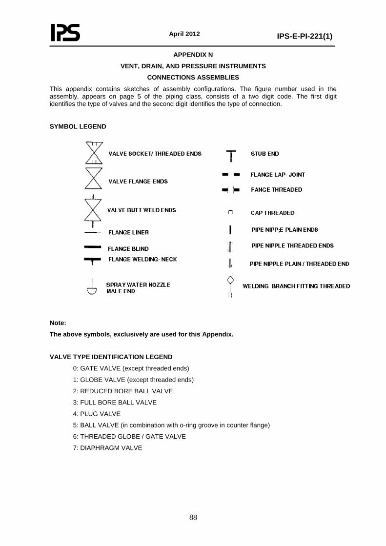
April 2012
IPS-E-PI-221(1)
88
APPENDIX N
VENT, DRAIN, AND PRESSURE INSTRUMENTS
CONNECTIONS ASSEMBLIES
This appendix contains sketches of assembly configurations. The figure number used in the assembly, appears on page 5 of the piping class, consists of a two digit code. The first digit identifies the type of valves and the second digit identifies the type of connection.
SYMBOL LEGEND
Note:
The above symbols, exclusively are used for this Appendix.
VALVE TYPE IDENTIFICATION LEGEND
0: GATE VALVE (except threaded ends)
1: GLOBE VALVE (except threaded ends)
2: REDUCED BORE BALL VALVE
3: FULL BORE BALL VALVE
4: PLUG VALVE
5: BALL VALVE (in combination with o-ring groove in counter flange)
6: THREADED GLOBE / GATE VALVE
7: DIAPHRAGM VALVE
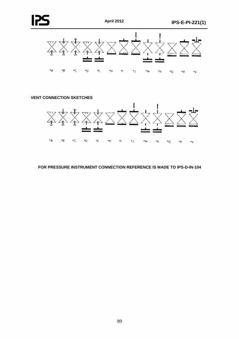
April 2012
IPS-E-PI-221(1)
89
VENT CONNECTION SKETCHES
FOR PRESSURE INSTRUMENT CONNECTION REFERENCE IS MADE TO IPS-D-IN-104
April 2012
IPS-E-PI-221(1)
90
PART TWO 0. INTRODUCTION This Standards is prepared in three parts, which are separately bindered as follow:
Part I General (guidance on the application of piping classes). Part II Piping class rating: PN 20 (150) and PN 50 (300). Part III Piping class rating: PN 100 (600), PN 150 (900) , PN 250 (1500) and PN 420 (2500).
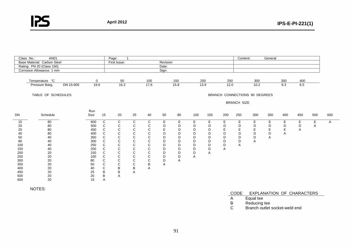
April 2012
IPS-E-PI-221(1)
91
Class No.: AN01 Page: 1 Content: General Base Material: Carbon Steel First Issue: Revision Rating: PN 20 (Class 150) Date: Corrosion Allowance: 1 mm Sign:
Temperature °C 0 50 100 150 200 250 300 350 400 Pressure Barg. DN 15-600 19.6 16.2 17.6 15.8 13.9 12.0 10.2 8.3 6.5
TABLE OF SCHEDULES BRANCH CONNECTIONS 90 DEGREES BRANCH SIZE
NOTES:
DN
Schedule
Run Size 15 20 25 40 50 80 100 150 200 250 300 350 400 450 500 600
15 20 25 40 50 80
100 150 200 250 300 350 400 450 500 600
80 80 80 80 40 40 40 40 20 20 20 20 20 20 20 20
600 C C C C E E E E E E E E E E E A 500 C C C C D D D D D D D D D D A 450 C C C C E D D D E E E E E A 400 C C C C D D D D D D D D A 350 C C C C D D D D D D D A 300 C C C C D D D D D D A 250 C C C C D D D D D A 200 C C C C D D D D A 150 C C C C D D D A 100 C C C C D D A 80 C C C C D A 50 C C C B A 40 C B B A 25 B B A 20 B A 15 A
CODE EXPLANATION OF CHARACTERS A Equal tee B Reducing tee C Branch outlet socket-weld end
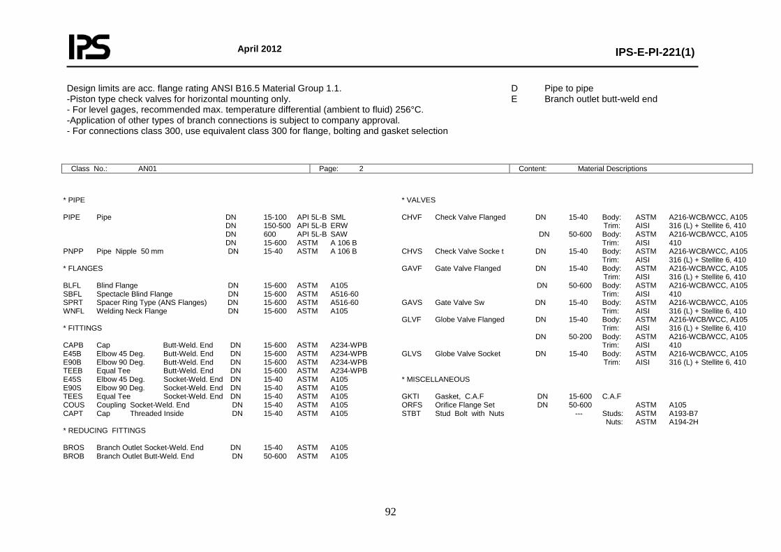
April 2012
IPS-E-PI-221(1)
92
Design limits are acc. flange rating ANSI B16.5 Material Group 1.1. -Piston type check valves for horizontal mounting only. - For level gages, recommended max. temperature differential (ambient to fluid) 256°C. -Application of other types of branch connections is subject to company approval. - For connections class 300, use equivalent class 300 for flange, bolting and gasket selection Class No.: AN01 Page: 2 Content: Material Descriptions
* PIPE PIPE Pipe DN 15-100 API 5L-B SML DN 150-500 API 5L-B ERW DN 600 API 5L-B SAW DN 15-600 ASTM A 106 B PNPP Pipe Nipple 50 mm DN 15-40 ASTM A 106 B * FLANGES BLFL Blind Flange DN 15-600 ASTM A105 SBFL Spectacle Blind Flange DN 15-600 ASTM A516-60 SPRT Spacer Ring Type (ANS Flanges) DN 15-600 ASTM A516-60 WNFL Welding Neck Flange DN 15-600 ASTM A105 * FITTINGS CAPB Cap Butt-Weld. End DN 15-600 ASTM A234-WPB E45B Elbow 45 Deg. Butt-Weld. End DN 15-600 ASTM A234-WPB E90B Elbow 90 Deg. Butt-Weld. End DN 15-600 ASTM A234-WPB TEEB Equal Tee Butt-Weld. End DN 15-600 ASTM A234-WPB E45S Elbow 45 Deg. Socket-Weld. End DN 15-40 ASTM A105 E90S Elbow 90 Deg. Socket-Weld. End DN 15-40 ASTM A105 TEES Equal Tee Socket-Weld. End DN 15-40 ASTM A105 COUS Coupling Socket-Weld. End DN 15-40 ASTM A105 CAPT Cap Threaded Inside DN 15-40 ASTM A105 * REDUCING FITTINGS BROS Branch Outlet Socket-Weld. End DN 15-40 ASTM A105 BROB Branch Outlet Butt-Weld. End DN 50-600 ASTM A105
* VALVES CHVF Check Valve Flanged DN 15-40 Body: ASTM A216-WCB/WCC, A105 Trim: AISI 316 (L) + Stellite 6, 410 DN 50-600 Body: ASTM A216-WCB/WCC, A105 Trim: AISI 410 CHVS Check Valve Socke t DN 15-40 Body: ASTM A216-WCB/WCC, A105 Trim: AISI 316 (L) + Stellite 6, 410 GAVF Gate Valve Flanged DN 15-40 Body: ASTM A216-WCB/WCC, A105 Trim: AISI 316 (L) + Stellite 6, 410 DN 50-600 Body: ASTM A216-WCB/WCC, A105 Trim: AISI 410 GAVS Gate Valve Sw DN 15-40 Body: ASTM A216-WCB/WCC, A105 Trim: AISI 316 (L) + Stellite 6, 410 GLVF Globe Valve Flanged DN 15-40 Body: ASTM A216-WCB/WCC, A105 Trim: AISI 316 (L) + Stellite 6, 410 DN 50-200 Body: ASTM A216-WCB/WCC, A105 Trim: AISI 410 GLVS Globe Valve Socket DN 15-40 Body: ASTM A216-WCB/WCC, A105 Trim: AISI 316 (L) + Stellite 6, 410 * MISCELLANEOUS GKTI Gasket, C.A.F DN 15-600 C.A.F ORFS Orifice Flange Set DN 50-600 ASTM A105 STBT Stud Bolt with Nuts --- Studs: ASTM A193-B7 Nuts: ASTM A194-2H
D Pipe to pipe E Branch outlet butt-weld end

April 2012
IPS-E-PI-221(1)
93
RECB Reducer Conc. Butt-Weld. End DN 20-600 ASTM A234-WPB REEB Reducer Ecc. Butt-Weld. End DN 20-600 ASTM A234-WPB TERB Tee Reducing Butt-Weld. End DN 20-600 ASTM A234-WPB TERS Tee Reducing Socket-Weld. End DN 20-40 ASTM A105 Notes: - For full material description see relevant MESC buying description. - Where both API 5L and ASTM A106 pipes are specified, preference is subject to company approval. - Where both butt-weld end and socket weld end Fitings are specified, preference is subject to company approval.
Class No.: AN01 Page: 3 Content: Piping Components
NOMINAL PIPE SIZE ITEM DESCRIPTION 15 20 25 40 50 80 100 150 200 250 300 350 400 450 500 600 * PIPE Pipe API-5L GR.B SML 74.13.21 * * * * * * * API-5L GR.B ERW 74.13.23 * * * * * * * * API-5L GR.B SAW 74.13.23 * ASTM A 106 B 74.30.21 * * * * * * * * * * * * * * * * Pipe nipple (50 mm) ASTM A 106 B 76.05.56 * * * * * FLANGES Blind Flange 76.62.10 * * * * * * * * * * * * * * * * Spectacle Blind Flange 76.88.06 * * * * * * * * * * * * * * * * Spacer Ring Type (ANS Flanges) 76.88.16 * * * * * * * * * * * * * * * * Welding Neck Flange 76.62.79 * * * * * * * * * * * * * * * * * FITTINGS Cap Butt-Weld. End 76.30.18 * * * * * * * * * * * * * * * * Elbow 45 Deg. Butt-Weld. End 76.30.38 * * * * * * * * * * * * * * * * Elbow 90 Deg. Butt-Weld. End 76.30.39 * * * * * * * * * * * * * * * * Elbow 90 Deg. Butt-Weld. End 76.30.40 * * * * * * * * * * * * * * * * Equal Tee Butt-Weld. End 76.30.84 * * * * * * * * * * * * * * * * Elbow 45 Deg. Socket-Weld. End 76.34.38 * * * * Elbow 90 Deg. Socket-Weld. End 76.34.39 * * * * Equal Tee Socket-Weld. End 76.34.84 * * * * Coupling Socket-Weld. End 76.34.28 * * * * Cap Threaded 76.05.18 * * * * * VALVES Check Valve Flanged 75.37.12 * * * * * * * * * * * * * * * * Check Valve Socket 75.56.13 * * * * Gate Valve Flanged 75.37.32 * * * * * * * * * * * * * * * * Gate Valve Sw 75.56.35 * * * *
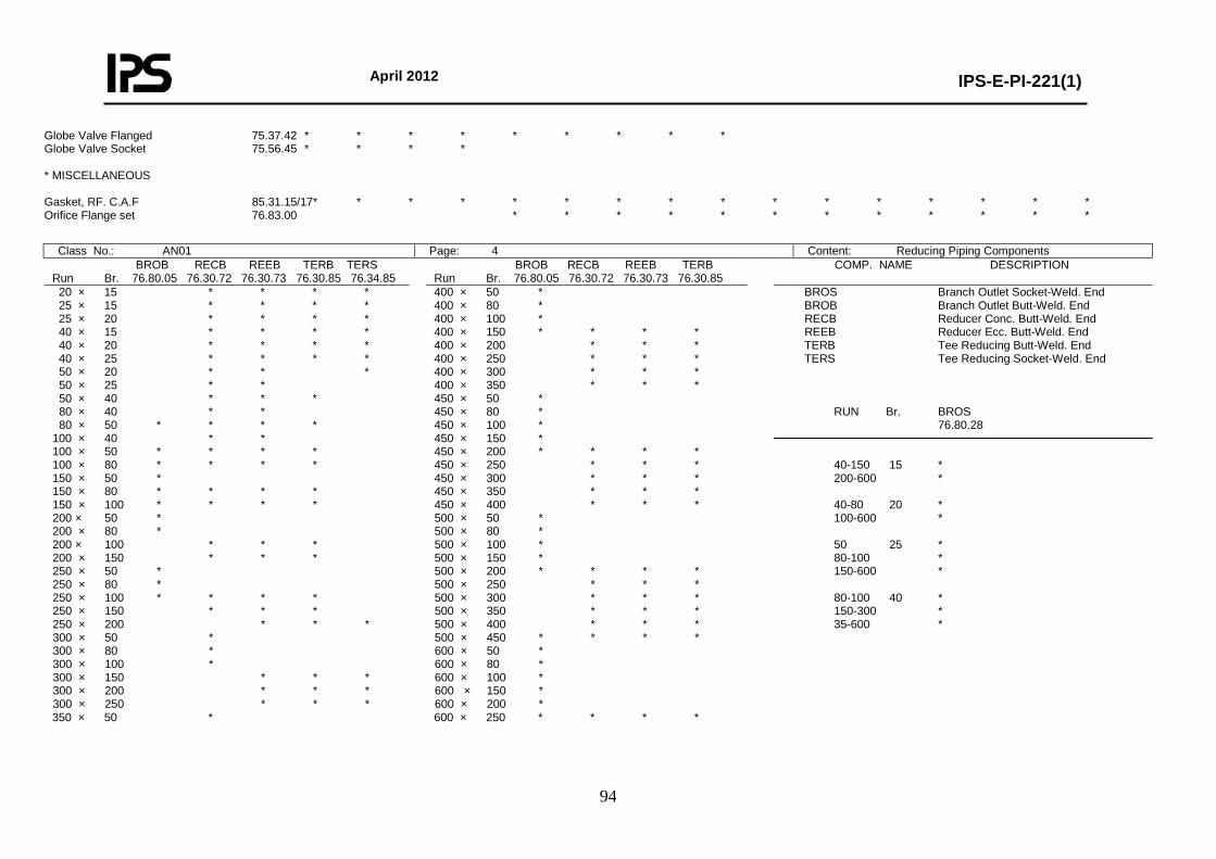
April 2012
IPS-E-PI-221(1)
94
Globe Valve Flanged 75.37.42 * * * * * * * * * Globe Valve Socket 75.56.45 * * * * * MISCELLANEOUS Gasket, RF. C.A.F 85.31.15/17* * * * * * * * * * * * * * * * Orifice Flange set 76.83.00 * * * * * * * * * * * *
Class No.: AN01 Page: 4 Content: Reducing Piping Components BROB RECB REEB TERB TERS Run Br. 76.80.05 76.30.72 76.30.73 76.30.85 76.34.85
BROB RECB REEB TERB Run Br. 76.80.05 76.30.72 76.30.73 76.30.85
COMP. NAME DESCRIPTION
20 × 15 * * * * 25 × 15 * * * * 25 × 20 * * * * 40 × 15 * * * * 40 × 20 * * * * 40 × 25 * * * * 50 × 20 * * * 50 × 25 * * 50 × 40 * * * 80 × 40 * * 80 × 50 * * * * 100 × 40 * * 100 × 50 * * * * 100 × 80 * * * * 150 × 50 * 150 × 80 * * * * 150 × 100 * * * * 200 × 50 * 200 × 80 * 200 × 100 * * * 200 × 150 * * * 250 × 50 * 250 × 80 * 250 × 100 * * * * 250 × 150 * * * 250 × 200 * * * 300 × 50 * 300 × 80 * 300 × 100 * 300 × 150 * * * 300 × 200 * * * 300 × 250 * * * 350 × 50 *
400 × 50 * 400 × 80 * 400 × 100 * 400 × 150 * * * * 400 × 200 * * * 400 × 250 * * * 400 × 300 * * * 400 × 350 * * * 450 × 50 * 450 × 80 * 450 × 100 * 450 × 150 * 450 × 200 * * * * 450 × 250 * * * 450 × 300 * * * 450 × 350 * * * 450 × 400 * * * 500 × 50 * 500 × 80 * 500 × 100 * 500 × 150 * 500 × 200 * * * * 500 × 250 * * * 500 × 300 * * * 500 × 350 * * * 500 × 400 * * * 500 × 450 * * * * 600 × 50 * 600 × 80 * 600 × 100 * 600 × 150 * 600 × 200 * 600 × 250 * * * *
BROS Branch Outlet Socket-Weld. End BROB Branch Outlet Butt-Weld. End RECB Reducer Conc. Butt-Weld. End REEB Reducer Ecc. Butt-Weld. End TERB Tee Reducing Butt-Weld. End TERS Tee Reducing Socket-Weld. End RUN Br. BROS 76.80.28 40-150 15 * 200-600 * 40-80 20 * 100-600 * 50 25 * 80-100 * 150-600 * 80-100 40 * 150-300 * 35-600 *
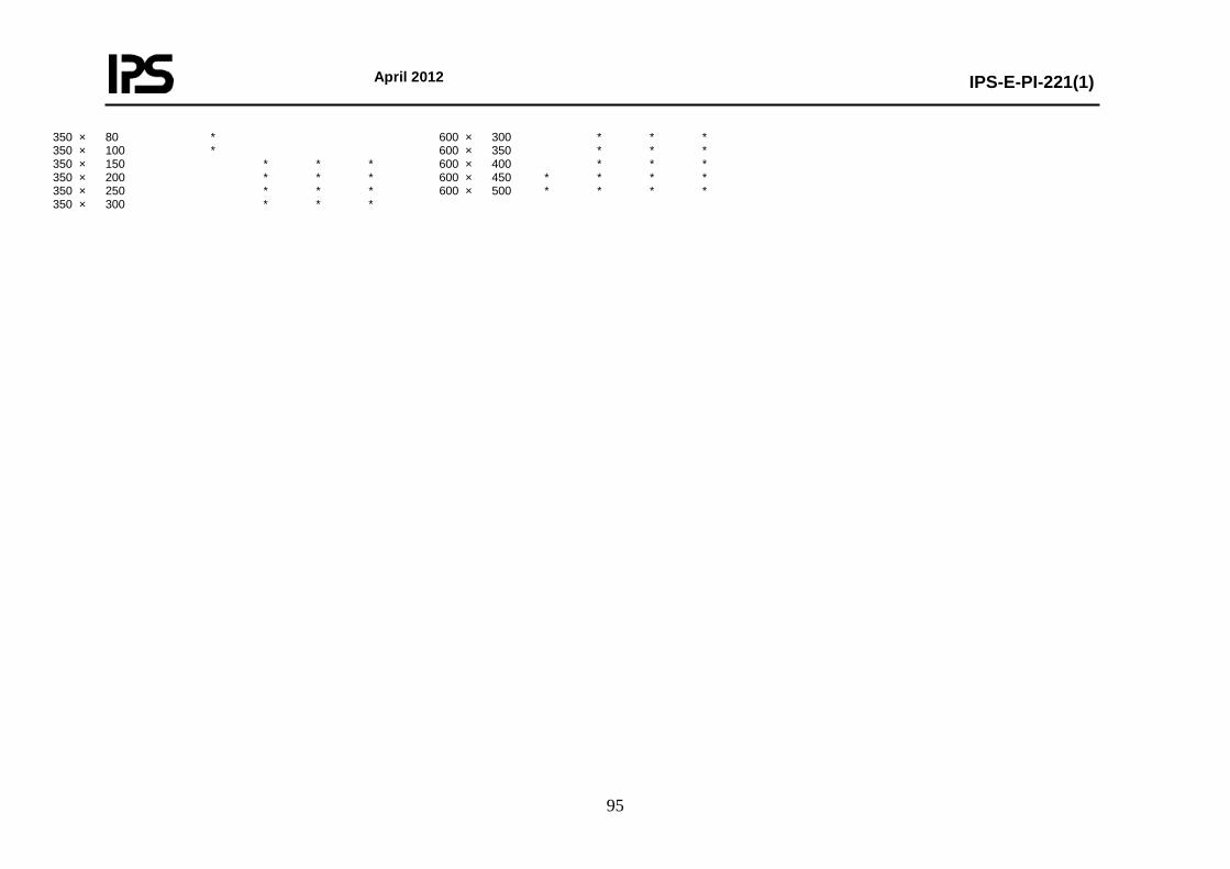
April 2012
IPS-E-PI-221(1)
95
350 × 80 * 350 × 100 * 350 × 150 * * * 350 × 200 * * * 350 × 250 * * * 350 × 300 * * *
600 × 300 * * * 600 × 350 * * * 600 × 400 * * * 600 × 450 * * * * 600 × 500 * * * *
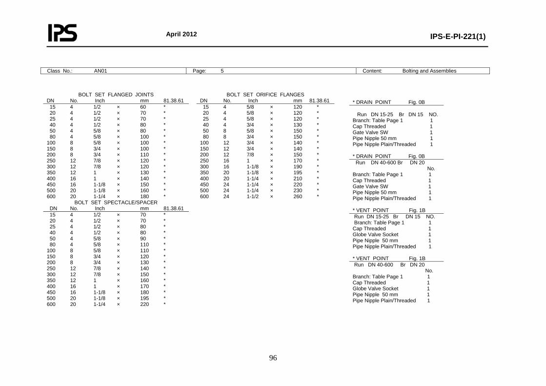
April 2012
IPS-E-PI-221(1)
96
Class No.: AN01 Page: 5 Content: Bolting and Assemblies
BOLT SET FLANGED JOINTS BOLT SET ORIFICE FLANGES DN No. Inch mm 81.38.61 DN No. Inch mm 81.38.61 15 4 1/2 × 60 * 20 4 1/2 × 70 * 25 4 1/2 × 70 * 40 4 1/2 × 80 * 50 4 5/8 × 80 * 80 4 5/8 × 100 * 100 8 5/8 × 100 * 150 8 3/4 × 100 * 200 8 3/4 × 110 * 250 12 7/8 × 120 * 300 12 7/8 × 120 * 350 12 1 × 130 * 400 16 1 × 140 * 450 16 1-1/8 × 150 * 500 20 1-1/8 × 160 * 600 20 1-1/4 × 180 *
BOLT SET SPECTACLE/SPACER
15 4 5/8 × 120 * 20 4 5/8 × 120 * 25 4 5/8 × 120 * 40 4 3/4 × 130 * 50 8 5/8 × 150 * 80 8 3/4 × 150 * 100 12 3/4 × 140 * 150 12 3/4 × 140 * 200 12 7/8 × 150 * 250 16 1 × 170 * 300 16 1-1/8 × 190 * 350 20 1-1/8 × 195 * 400 20 1-1/4 × 210 * 450 24 1-1/4 × 220 * 500 24 1-1/4 × 230 * 600 24 1-1/2 × 260 *
DN No. Inch mm 81.38.61 15 4 1/2 × 70 * 20 4 1/2 × 70 * 25 4 1/2 × 80 * 40 4 1/2 × 80 * 50 4 5/8 × 90 * 80 4 5/8 × 110 * 100 8 5/8 × 110 * 150 8 3/4 × 120 * 200 8 3/4 × 130 * 250 12 7/8 × 140 * 300 12 7/8 × 150 * 350 12 1 × 160 * 400 16 1 × 170 * 450 16 1-1/8 × 180 * 500 20 1-1/8 × 195 * 600 20 1-1/4 × 220 *
* DRAIN POINT Fig. 0B Run DN 15-25 Br DN 15 NO. Branch: Table Page 1 1 Cap Threaded 1 Gate Valve SW 1 Pipe Nipple 50 mm 1 Pipe Nipple Plain/Threaded 1 * DRAIN POINT Fig. 0B Run DN 40-600 Br DN 20 No. Branch: Table Page 1 1 Cap Threaded 1 Gate Valve SW 1 Pipe Nipple 50 mm 1 Pipe Nipple Plain/Threaded 1 * VENT POINT Fig. 1B Run DN 15-25 Br DN 15 NO. Branch: Table Page 1 1 Cap Threaded 1 Globe Valve Socket 1 Pipe Nipple 50 mm 1 Pipe Nipple Plain/Threaded 1 * VENT POINT Fig. 1B Run DN 40-600 Br DN 20 No. Branch: Table Page 1 1 Cap Threaded 1 Globe Valve Socket 1 Pipe Nipple 50 mm 1 Pipe Nipple Plain/Threaded 1

April 2012
IPS-E-PI-221(1)
97
Class No.: AN02 Page: 1 Content: General Base Material: Carbon Steel First Issue: Revision: Rating: PN 20 (Class 150) Date: Corrosion Allowance: 1 mm Sign:
Temperature °C 0 50 75 100 125 150 175 300 Pressure Barg DN 15-80
DN 100-150 DN 200-600
19.6 19.6 19.6
19.2 19.2 19.2
18.4 18.4 18.4
17.6 17.6 17.6
16.7 16.7 16.7
15.8 15.8 15.8
14.8 14.8 12.0
110 9.0 7.0
Notes:
-Design limits are acc. flange rating ANSI B16.5 Material Group 1.1 and ball valve rating acc. BS 5351. -Piston type check valves for horizontal mounting only -Application of other types of branch connections is subject to company approval - For connections class 300, use equivalent class 300 for flange, bolting and gasket selection.
TABLE OF SCHEDULES BRANCH CONNECTIONS 90 DEGREES BRANCH SIZE
DN Schedule Run Size 15 20 25 40 50 80 100 150 200 250 300 350 400 450 500 600
15 20 25 40 50 80
100 150 200 250 300 350 400 450 500 600
80 80 80 80 40 40 40 40 20 20 20 20 20 20 20 20
600 C C C C E E E E E E E E E E E A 500 C C C C E E E E E E E E E E A 450 C C C C E E E E E E E E E A 400 C C C C E E E E E E E E A 350 C C C C D D D D D D D A 300 C C C C E E E E E E A 250 C C C C D D D D D A 200 C C C C D D D D A 150 C C C C D D D A 100 C C C C D D A 80 C C C C D A 50 C C C B A 40 C B B A 25 B B A 20 B A 15 A
CODE EXPLANATION OF CHARACTERS A Equal tee B Reducing tee C Branch outlet socket-weld. End D Pipe to pipe E Branch outlet butt-weld. end
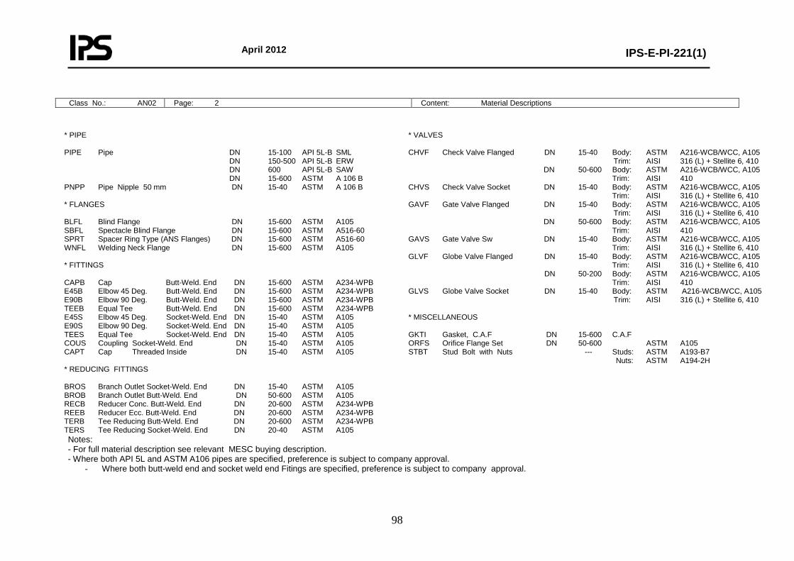
April 2012
IPS-E-PI-221(1)
98
Class No.: AN02 Page: 2 Content: Material Descriptions
* PIPE PIPE Pipe DN 15-100 API 5L-B SML DN 150-500 API 5L-B ERW DN 600 API 5L-B SAW DN 15-600 ASTM A 106 B PNPP Pipe Nipple 50 mm DN 15-40 ASTM A 106 B * FLANGES BLFL Blind Flange DN 15-600 ASTM A105 SBFL Spectacle Blind Flange DN 15-600 ASTM A516-60 SPRT Spacer Ring Type (ANS Flanges) DN 15-600 ASTM A516-60 WNFL Welding Neck Flange DN 15-600 ASTM A105 * FITTINGS CAPB Cap Butt-Weld. End DN 15-600 ASTM A234-WPB E45B Elbow 45 Deg. Butt-Weld. End DN 15-600 ASTM A234-WPB E90B Elbow 90 Deg. Butt-Weld. End DN 15-600 ASTM A234-WPB TEEB Equal Tee Butt-Weld. End DN 15-600 ASTM A234-WPB E45S Elbow 45 Deg. Socket-Weld. End DN 15-40 ASTM A105 E90S Elbow 90 Deg. Socket-Weld. End DN 15-40 ASTM A105 TEES Equal Tee Socket-Weld. End DN 15-40 ASTM A105 COUS Coupling Socket-Weld. End DN 15-40 ASTM A105 CAPT Cap Threaded Inside DN 15-40 ASTM A105 * REDUCING FITTINGS BROS Branch Outlet Socket-Weld. End DN 15-40 ASTM A105 BROB Branch Outlet Butt-Weld. End DN 50-600 ASTM A105 RECB Reducer Conc. Butt-Weld. End DN 20-600 ASTM A234-WPB REEB Reducer Ecc. Butt-Weld. End DN 20-600 ASTM A234-WPB TERB Tee Reducing Butt-Weld. End DN 20-600 ASTM A234-WPB TERS Tee Reducing Socket-Weld. End DN 20-40 ASTM A105
* VALVES CHVF Check Valve Flanged DN 15-40 Body: ASTM A216-WCB/WCC, A105 Trim: AISI 316 (L) + Stellite 6, 410 DN 50-600 Body: ASTM A216-WCB/WCC, A105 Trim: AISI 410 CHVS Check Valve Socket DN 15-40 Body: ASTM A216-WCB/WCC, A105 Trim: AISI 316 (L) + Stellite 6, 410 GAVF Gate Valve Flanged DN 15-40 Body: ASTM A216-WCB/WCC, A105 Trim: AISI 316 (L) + Stellite 6, 410 DN 50-600 Body: ASTM A216-WCB/WCC, A105 Trim: AISI 410 GAVS Gate Valve Sw DN 15-40 Body: ASTM A216-WCB/WCC, A105 Trim: AISI 316 (L) + Stellite 6, 410 GLVF Globe Valve Flanged DN 15-40 Body: ASTM A216-WCB/WCC, A105 Trim: AISI 316 (L) + Stellite 6, 410 DN 50-200 Body: ASTM A216-WCB/WCC, A105 Trim: AISI 410 GLVS Globe Valve Socket DN 15-40 Body: ASTM A216-WCB/WCC, A105 Trim: AISI 316 (L) + Stellite 6, 410 * MISCELLANEOUS GKTI Gasket, C.A.F DN 15-600 C.A.F ORFS Orifice Flange Set DN 50-600 ASTM A105 STBT Stud Bolt with Nuts --- Studs: ASTM A193-B7 Nuts: ASTM A194-2H
Notes: - For full material description see relevant MESC buying description. - Where both API 5L and ASTM A106 pipes are specified, preference is subject to company approval.
- Where both butt-weld end and socket weld end Fitings are specified, preference is subject to company approval.
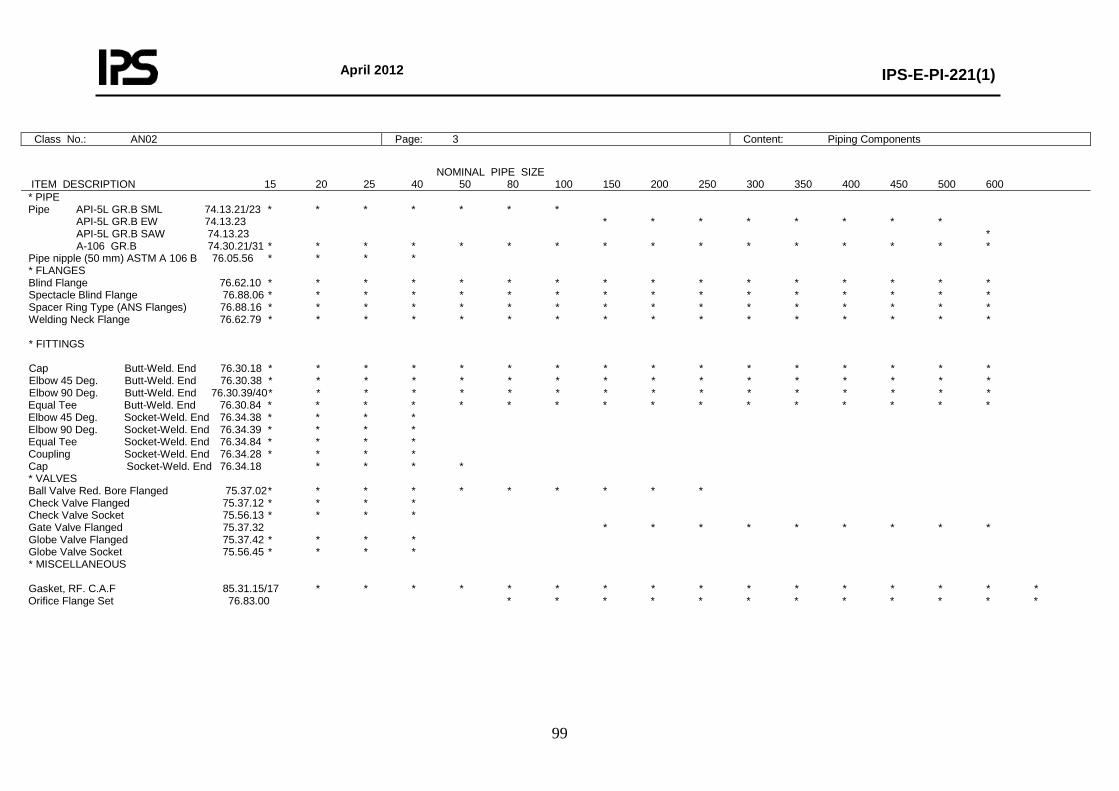
April 2012
IPS-E-PI-221(1)
99
Class No.: AN02 Page: 3 Content: Piping Components
NOMINAL PIPE SIZE ITEM DESCRIPTION 15 20 25 40 50 80 100 150 200 250 300 350 400 450 500 600 * PIPE Pipe API-5L GR.B SML 74.13.21/23 * * * * * * * API-5L GR.B EW 74.13.23 * * * * * * * * API-5L GR.B SAW 74.13.23 * A-106 GR.B 74.30.21/31 * * * * * * * * * * * * * * * * Pipe nipple (50 mm) ASTM A 106 B 76.05.56 * * * * * FLANGES Blind Flange 76.62.10 * * * * * * * * * * * * * * * * Spectacle Blind Flange 76.88.06 * * * * * * * * * * * * * * * * Spacer Ring Type (ANS Flanges) 76.88.16 * * * * * * * * * * * * * * * * Welding Neck Flange 76.62.79 * * * * * * * * * * * * * * * * * FITTINGS Cap Butt-Weld. End 76.30.18 * * * * * * * * * * * * * * * * Elbow 45 Deg. Butt-Weld. End 76.30.38 * * * * * * * * * * * * * * * * Elbow 90 Deg. Butt-Weld. End 76.30.39/40 * * * * * * * * * * * * * * * * Equal Tee Butt-Weld. End 76.30.84 * * * * * * * * * * * * * * * * Elbow 45 Deg. Socket-Weld. End 76.34.38 * * * * Elbow 90 Deg. Socket-Weld. End 76.34.39 * * * * Equal Tee Socket-Weld. End 76.34.84 * * * * Coupling Socket-Weld. End 76.34.28 * * * * Cap Socket-Weld. End 76.34.18 * * * * * VALVES Ball Valve Red. Bore Flanged 75.37.02 * * * * * * * * * * Check Valve Flanged 75.37.12 * * * * Check Valve Socket 75.56.13 * * * * Gate Valve Flanged 75.37.32 * * * * * * * * * Globe Valve Flanged 75.37.42 * * * * Globe Valve Socket 75.56.45 * * * * * MISCELLANEOUS Gasket, RF. C.A.F 85.31.15/17 * * * * * * * * * * * * * * * * Orifice Flange Set 76.83.00 * * * * * * * * * * * *
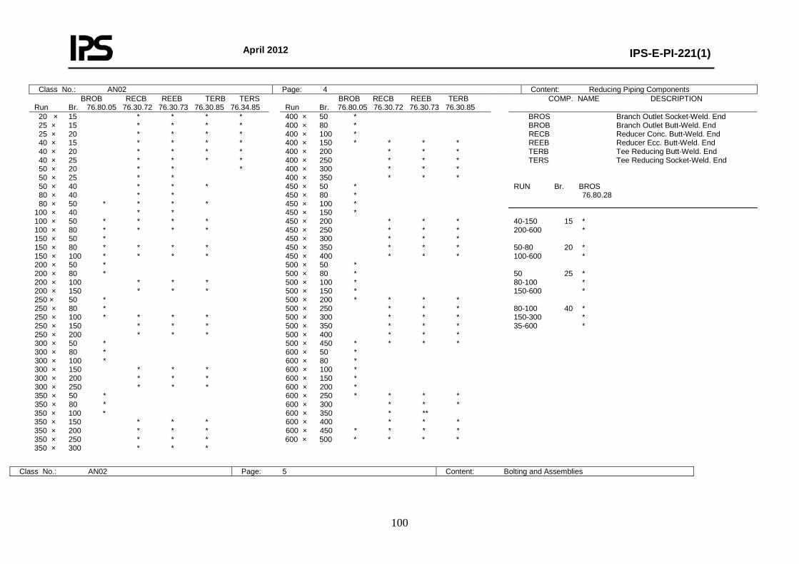
April 2012
IPS-E-PI-221(1)
100
Class No.: AN02 Page: 4 Content: Reducing Piping Components BROB RECB REEB TERB TERS Run Br. 76.80.05 76.30.72 76.30.73 76.30.85 76.34.85
BROB RECB REEB TERB Run Br. 76.80.05 76.30.72 76.30.73 76.30.85
COMP. NAME DESCRIPTION
20 × 15 * * * * 25 × 15 * * * * 25 × 20 * * * * 40 × 15 * * * * 40 × 20 * * * * 40 × 25 * * * * 50 × 20 * * * 50 × 25 * * 50 × 40 * * * 80 × 40 * * 80 × 50 * * * * 100 × 40 * * 100 × 50 * * * * 100 × 80 * * * * 150 × 50 * 150 × 80 * * * * 150 × 100 * * * * 200 × 50 * 200 × 80 * 200 × 100 * * * 200 × 150 * * * 250 × 50 * 250 × 80 * 250 × 100 * * * * 250 × 150 * * * 250 × 200 * * * 300 × 50 * 300 × 80 * 300 × 100 * 300 × 150 * * * 300 × 200 * * * 300 × 250 * * * 350 × 50 * 350 × 80 * 350 × 100 * 350 × 150 * * * 350 × 200 * * * 350 × 250 * * * 350 × 300 * * *
400 × 50 * 400 × 80 * 400 × 100 * 400 × 150 * * * * 400 × 200 * * * 400 × 250 * * * 400 × 300 * * * 400 × 350 * * * 450 × 50 * 450 × 80 * 450 × 100 * 450 × 150 * 450 × 200 * * * 450 × 250 * * * 450 × 300 * * * 450 × 350 * * * 450 × 400 * * * 500 × 50 * 500 × 80 * 500 × 100 * 500 × 150 * 500 × 200 * * * * 500 × 250 * * * 500 × 300 * * * 500 × 350 * * * 500 × 400 * * * 500 × 450 * * * * 600 × 50 * 600 × 80 * 600 × 100 * 600 × 150 * 600 × 200 * 600 × 250 * * * * 600 × 300 * * * 600 × 350 * ** 600 × 400 * * * 600 × 450 * * * * 600 × 500 * * * *
BROS Branch Outlet Socket-Weld. End BROB Branch Outlet Butt-Weld. End RECB Reducer Conc. Butt-Weld. End REEB Reducer Ecc. Butt-Weld. End TERB Tee Reducing Butt-Weld. End TERS Tee Reducing Socket-Weld. End RUN Br. BROS 76.80.28 40-150 15 * 200-600 * 50-80 20 * 100-600 * 50 25 * 80-100 * 150-600 * 80-100 40 * 150-300 * 35-600 *
Class No.: AN02 Page: 5 Content: Bolting and Assemblies
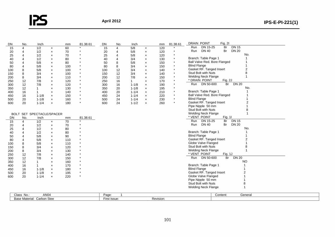
April 2012
IPS-E-PI-221(1)
101
DRAIN POINT Fig. 2I Run DN 15-25 Br DN 15 Run DN 40 Br DN 20 No. Branch: Table Page 1 1 Ball Valve Red. Bore Flanged 1 Blind Flange 1 Gasket RF. Tanged Insert 2 Stud Bolt with Nuts 8 Welding Neck Flange 1 * DRAIN POINT Fig. 2J Run DN 50-600 Br DN 20 No. Branch: Table Page 1 1 Ball Valve Red. Bore Flanged 1 Blind Flange 1 Gasket RF. Tanged Insert 2 Pipe Nipple 50 mm 1 Stud Bolt with Nuts 8 Welding Neck Flange 1 * VENT POINT Fig. 1I Run DN 15-25 Br DN 15 Run DN 40 Br DN 20 No. Branch: Table Page 1 1 Blind Flange 1 Gasket RF. Tanged Insert 2 Globe Valve Flanged 1 Stud Bolt with Nuts 8 Welding Neck Flange 1 * VENT POINT Fig. 1J Run DN 50-600 Br DN 20 NO Branch: Table Page 1 1 Blind Flange 1 Gasket RF. Tanged Insert 2 Globe Valve Flanged 1 Pipe Nipple 50 mm 1 Stud Bolt with Nuts 8 Welding Neck Flange 1
Class No.: AN04 Page: 1 Content: General Base Material: Carbon Stee First Issue: Revision:
DN No. Inch mm 81.38.61 DN No. Inch mm 81.38.61 15 4 1/2 × 60 * 20 4 1/2 × 70 * 25 4 1/2 × 70 * 40 4 1/2 × 80 * 50 4 5/8 × 80 * 80 4 5/8 × 100 * 100 8 5/8 × 100 * 150 8 3/4 × 100 * 200 8 3/4 × 110 * 250 12 7/8 × 120 * 300 12 7/8 × 120 * 350 12 1 × 130 * 400 16 1 × 140 * 450 16 1-1/8 × 150 * 500 20 1-1/8 × 160 * 600 20 1-1/4 × 180 * BOLT SET SPECTACLE/SPACER
15 4 5/8 × 120 * 20 4 5/8 × 120 * 25 4 5/8 × 120 * 40 4 3/4 × 130 * 50 8 5/8 × 150 * 80 8 3/4 × 150 * 100 12 3/4 × 140 * 150 12 3/4 × 140 * 200 12 7/8 × 150 * 250 16 1 × 170 * 300 16 1-1/8 × 190 * 350 20 1-1/8 × 195 * 400 20 1-1/4 × 210 * 450 24 1-1/4 × 220 * 500 24 1-1/4 × 230 * 600 24 1-1/2 × 260 *
DN No. Inch mm 81.38.61 15 4 1/2 × 70 * 20 4 1/2 × 70 * 25 4 1/2 × 80 * 40 4 1/2 × 80 * 50 4 5/8 × 90 * 80 4 5/8 × 110 * 100 8 5/8 × 110 * 150 8 3/4 × 120 * 200 8 3/4 × 130 * 250 12 7/8 × 140 * 300 12 7/8 × 150 * 350 12 1 × 160 * 400 16 1 × 170 * 450 16 1-1/8 × 180 * 500 20 1-1/8 × 195 * 600 20 1-1/4 × 220 *
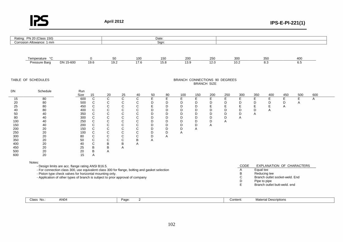
April 2012
IPS-E-PI-221(1)
102
Rating: PN 20 (Class 150) Date: Corrosion Allowance: 1 mm Sign:
Temperature °C 0 50 100 150 200 250 300 350 400 Pressure Barg DN 15-600 19.6 19.2 17.6 15.8 13.9 12.0 10.2 8.3 6.5
Notes:
- Design limits are acc. flange rating ANSI B16.5. - For connection class 300, use equivalent class 300 for flange, bolting and gasket selection - Piston type check valves for horizontal mounting only. - Application of other types of branch is subject to prior approval of company
Class No.: AN04 Page: 2 Content: Material Descriptions
TABLE OF SCHEDULES BRANCH CONNECTIONS 90 DEGREES BRANCH SIZE
DN Schedule Run
Size 15 20 25 40 50 80 100 150 200 250 300 350 400 450 500 600 15 20 25 40 50 80
100 150 200 250 300 350 400 450 500 600
80 80 80 80 40 40 40 40 20 20 20 20 20 20 20 20
600 C C C C E E E E E E E E E E E A 500 C C C C D D D D D D D D D D A 450 C C C C E D D D E E E E E A 400 C C C C D D D D D D D D A 350 C C C C D D D D D D D A 300 C C C C D D D D D D A 250 C C C C D D D D D A 200 C C C C D D D D A 150 C C C C D D D A 100 C C C C D D A 80 C C C C D A 50 C C C B A 40 C B B A 25 B B A 20 B A 15 A
CODE EXPLANATION OF CHARACTERS A Equal tee B Reducing tee C Branch outlet socket-weld. End D Pipe to pipe E Branch outlet butt-weld. end
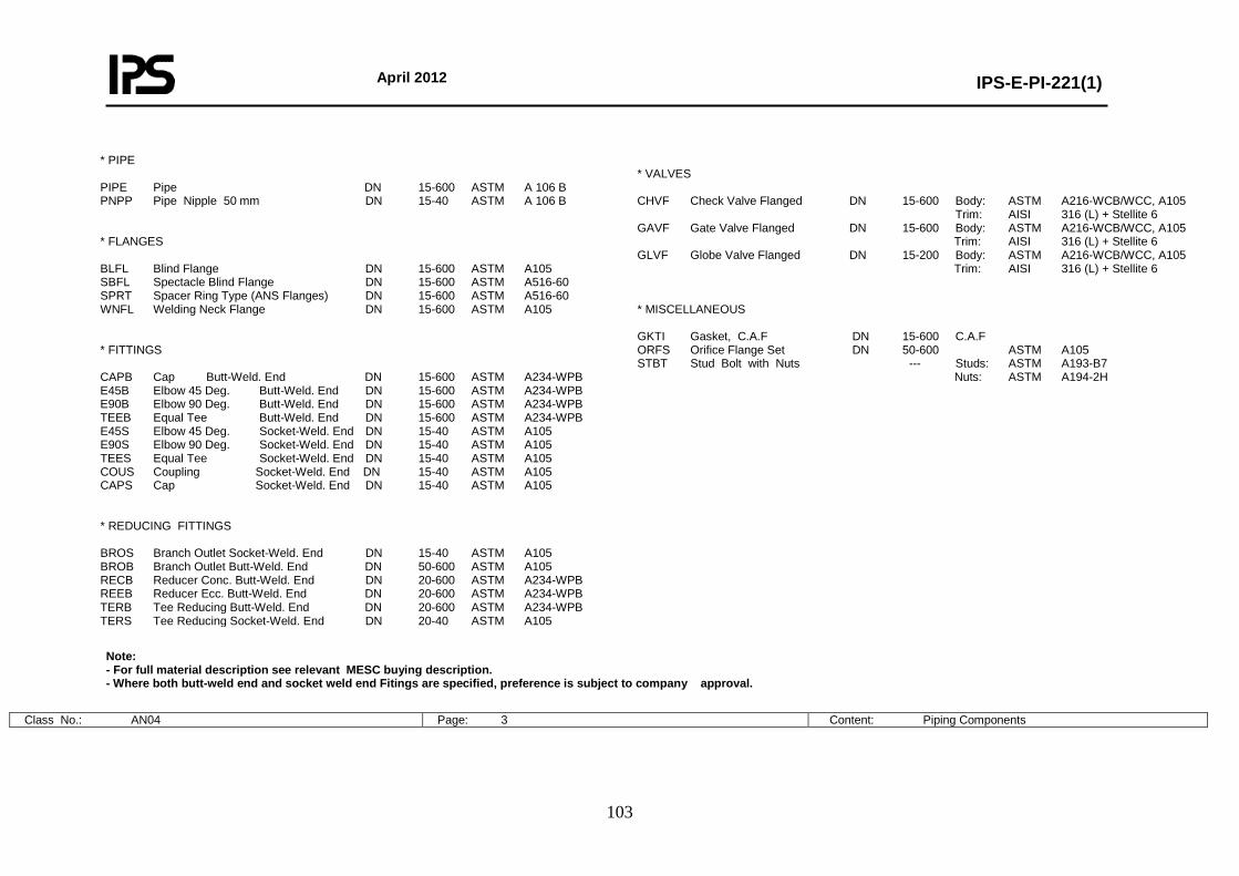
April 2012
IPS-E-PI-221(1)
103
* PIPE PIPE Pipe DN 15-600 ASTM A 106 B PNPP Pipe Nipple 50 mm DN 15-40 ASTM A 106 B * FLANGES BLFL Blind Flange DN 15-600 ASTM A105 SBFL Spectacle Blind Flange DN 15-600 ASTM A516-60 SPRT Spacer Ring Type (ANS Flanges) DN 15-600 ASTM A516-60 WNFL Welding Neck Flange DN 15-600 ASTM A105 * FITTINGS CAPB Cap Butt-Weld. End DN 15-600 ASTM A234-WPB E45B Elbow 45 Deg. Butt-Weld. End DN 15-600 ASTM A234-WPB E90B Elbow 90 Deg. Butt-Weld. End DN 15-600 ASTM A234-WPB TEEB Equal Tee Butt-Weld. End DN 15-600 ASTM A234-WPB E45S Elbow 45 Deg. Socket-Weld. End DN 15-40 ASTM A105 E90S Elbow 90 Deg. Socket-Weld. End DN 15-40 ASTM A105 TEES Equal Tee Socket-Weld. End DN 15-40 ASTM A105 COUS Coupling Socket-Weld. End DN 15-40 ASTM A105 CAPS Cap Socket-Weld. End DN 15-40 ASTM A105 * REDUCING FITTINGS BROS Branch Outlet Socket-Weld. End DN 15-40 ASTM A105 BROB Branch Outlet Butt-Weld. End DN 50-600 ASTM A105 RECB Reducer Conc. Butt-Weld. End DN 20-600 ASTM A234-WPB REEB Reducer Ecc. Butt-Weld. End DN 20-600 ASTM A234-WPB TERB Tee Reducing Butt-Weld. End DN 20-600 ASTM A234-WPB TERS Tee Reducing Socket-Weld. End DN 20-40 ASTM A105
* VALVES CHVF Check Valve Flanged DN 15-600 Body: ASTM A216-WCB/WCC, A105 Trim: AISI 316 (L) + Stellite 6 GAVF Gate Valve Flanged DN 15-600 Body: ASTM A216-WCB/WCC, A105 Trim: AISI 316 (L) + Stellite 6 GLVF Globe Valve Flanged DN 15-200 Body: ASTM A216-WCB/WCC, A105 Trim: AISI 316 (L) + Stellite 6 * MISCELLANEOUS GKTI Gasket, C.A.F DN 15-600 C.A.F ORFS Orifice Flange Set DN 50-600 ASTM A105 STBT Stud Bolt with Nuts --- Studs: ASTM A193-B7 Nuts: ASTM A194-2H
Note: - For full material description see relevant MESC buying description. - Where both butt-weld end and socket weld end Fitings are specified, preference is subject to company approval.
Class No.: AN04 Page: 3 Content: Piping Components
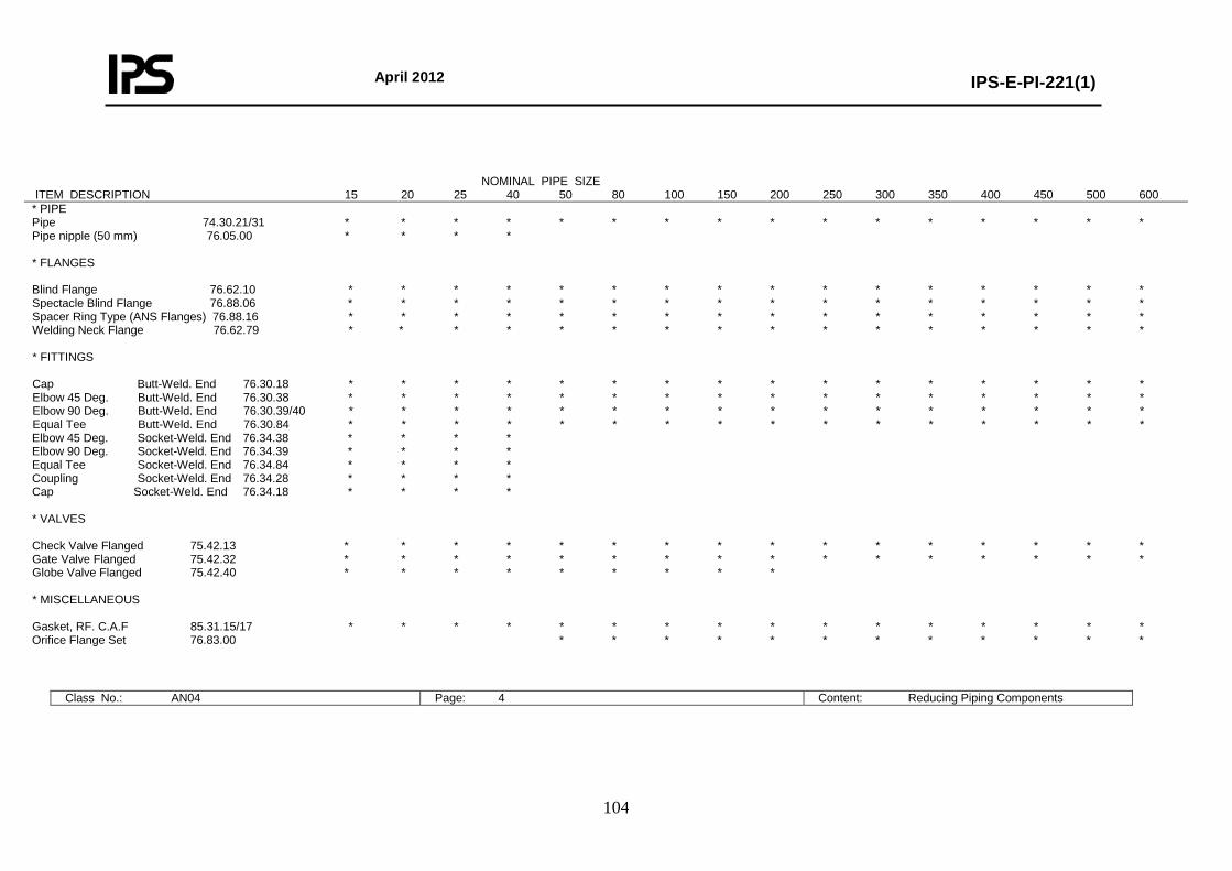
April 2012
IPS-E-PI-221(1)
104
NOMINAL PIPE SIZE ITEM DESCRIPTION 15 20 25 40 50 80 100 150 200 250 300 350 400 450 500 600 * PIPE Pipe 74.30.21/31 * * * * * * * * * * * * * * * * Pipe nipple (50 mm) 76.05.00 * * * * * FLANGES Blind Flange 76.62.10 * * * * * * * * * * * * * * * * Spectacle Blind Flange 76.88.06 * * * * * * * * * * * * * * * * Spacer Ring Type (ANS Flanges) 76.88.16 * * * * * * * * * * * * * * * * Welding Neck Flange 76.62.79 * * * * * * * * * * * * * * * * * FITTINGS Cap Butt-Weld. End 76.30.18 * * * * * * * * * * * * * * * * Elbow 45 Deg. Butt-Weld. End 76.30.38 * * * * * * * * * * * * * * * * Elbow 90 Deg. Butt-Weld. End 76.30.39/40 * * * * * * * * * * * * * * * * Equal Tee Butt-Weld. End 76.30.84 * * * * * * * * * * * * * * * * Elbow 45 Deg. Socket-Weld. End 76.34.38 * * * * Elbow 90 Deg. Socket-Weld. End 76.34.39 * * * * Equal Tee Socket-Weld. End 76.34.84 * * * * Coupling Socket-Weld. End 76.34.28 * * * * Cap Socket-Weld. End 76.34.18 * * * * * VALVES Check Valve Flanged 75.42.13 * * * * * * * * * * * * * * * * Gate Valve Flanged 75.42.32 * * * * * * * * * * * * * * * * Globe Valve Flanged 75.42.40 * * * * * * * * * * MISCELLANEOUS Gasket, RF. C.A.F 85.31.15/17 * * * * * * * * * * * * * * * * Orifice Flange Set 76.83.00 * * * * * * * * * * * *
Class No.: AN04 Page: 4 Content: Reducing Piping Components
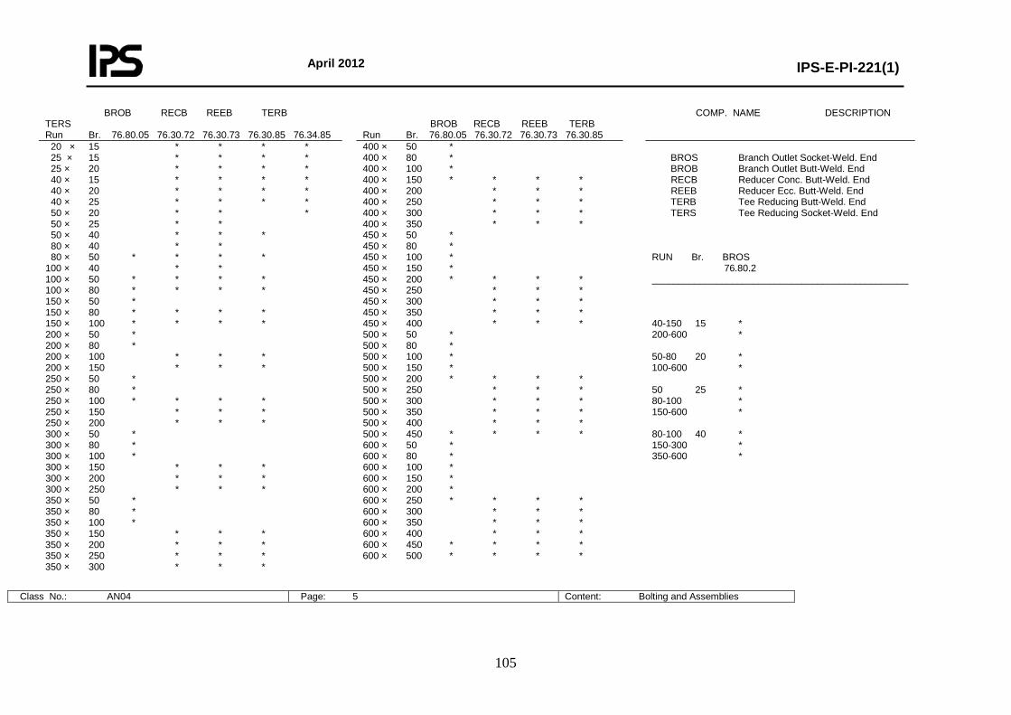
April 2012
IPS-E-PI-221(1)
105
BROB RECB REEB TERB TERS Run Br. 76.80.05 76.30.72 76.30.73 76.30.85 76.34.85
BROB RECB REEB TERB Run Br. 76.80.05 76.30.72 76.30.73 76.30.85
COMP. NAME DESCRIPTION
20 × 15 * * * * 25 × 15 * * * * 25 × 20 * * * * 40 × 15 * * * * 40 × 20 * * * * 40 × 25 * * * * 50 × 20 * * * 50 × 25 * * 50 × 40 * * * 80 × 40 * * 80 × 50 * * * * 100 × 40 * * 100 × 50 * * * * 100 × 80 * * * * 150 × 50 * 150 × 80 * * * * 150 × 100 * * * * 200 × 50 * 200 × 80 * 200 × 100 * * * 200 × 150 * * * 250 × 50 * 250 × 80 * 250 × 100 * * * * 250 × 150 * * * 250 × 200 * * * 300 × 50 * 300 × 80 * 300 × 100 * 300 × 150 * * * 300 × 200 * * * 300 × 250 * * * 350 × 50 * 350 × 80 * 350 × 100 * 350 × 150 * * * 350 × 200 * * * 350 × 250 * * * 350 × 300 * * *
400 × 50 * 400 × 80 * 400 × 100 * 400 × 150 * * * * 400 × 200 * * * 400 × 250 * * * 400 × 300 * * * 400 × 350 * * * 450 × 50 * 450 × 80 * 450 × 100 * 450 × 150 * 450 × 200 * * * * 450 × 250 * * * 450 × 300 * * * 450 × 350 * * * 450 × 400 * * * 500 × 50 * 500 × 80 * 500 × 100 * 500 × 150 * 500 × 200 * * * * 500 × 250 * * * 500 × 300 * * * 500 × 350 * * * 500 × 400 * * * 500 × 450 * * * * 600 × 50 * 600 × 80 * 600 × 100 * 600 × 150 * 600 × 200 * 600 × 250 * * * * 600 × 300 * * * 600 × 350 * * * 600 × 400 * * * 600 × 450 * * * * 600 × 500 * * * *
BROS Branch Outlet Socket-Weld. End BROB Branch Outlet Butt-Weld. End RECB Reducer Conc. Butt-Weld. End REEB Reducer Ecc. Butt-Weld. End TERB Tee Reducing Butt-Weld. End TERS Tee Reducing Socket-Weld. End RUN Br. BROS 76.80.2 ________________________________________________ 40-150 15 * 200-600 * 50-80 20 * 100-600 * 50 25 * 80-100 * 150-600 * 80-100 40 * 150-300 * 350-600 *
Class No.: AN04 Page: 5 Content: Bolting and Assemblies
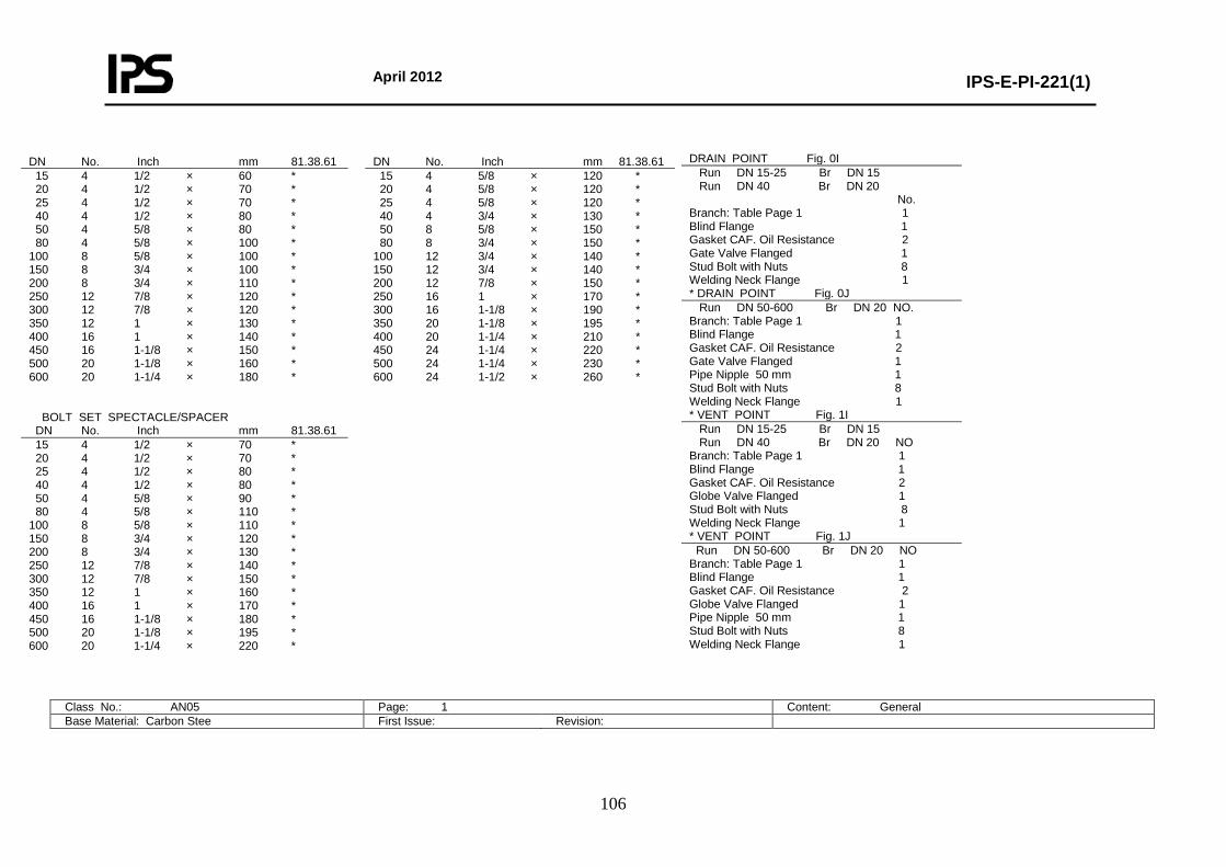
April 2012
IPS-E-PI-221(1)
106
DRAIN POINT Fig. 0I Run DN 15-25 Br DN 15 Run DN 40 Br DN 20 No. Branch: Table Page 1 1 Blind Flange 1 Gasket CAF. Oil Resistance 2 Gate Valve Flanged 1 Stud Bolt with Nuts 8 Welding Neck Flange 1 * DRAIN POINT Fig. 0J Run DN 50-600 Br DN 20 NO. Branch: Table Page 1 1 Blind Flange 1 Gasket CAF. Oil Resistance 2 Gate Valve Flanged 1 Pipe Nipple 50 mm 1 Stud Bolt with Nuts 8 Welding Neck Flange 1 * VENT POINT Fig. 1I Run DN 15-25 Br DN 15 Run DN 40 Br DN 20 NO Branch: Table Page 1 1 Blind Flange 1 Gasket CAF. Oil Resistance 2 Globe Valve Flanged 1 Stud Bolt with Nuts 8 Welding Neck Flange 1 * VENT POINT Fig. 1J Run DN 50-600 Br DN 20 NO Branch: Table Page 1 1 Blind Flange 1 Gasket CAF. Oil Resistance 2 Globe Valve Flanged 1 Pipe Nipple 50 mm 1 Stud Bolt with Nuts 8 Welding Neck Flange 1
Class No.: AN05 Page: 1 Content: General Base Material: Carbon Stee First Issue: Revision:
DN No. Inch mm 81.38.61 DN No. Inch mm 81.38.61 15 4 1/2 × 60 * 20 4 1/2 × 70 * 25 4 1/2 × 70 * 40 4 1/2 × 80 * 50 4 5/8 × 80 * 80 4 5/8 × 100 * 100 8 5/8 × 100 * 150 8 3/4 × 100 * 200 8 3/4 × 110 * 250 12 7/8 × 120 * 300 12 7/8 × 120 * 350 12 1 × 130 * 400 16 1 × 140 * 450 16 1-1/8 × 150 * 500 20 1-1/8 × 160 * 600 20 1-1/4 × 180 * BOLT SET SPECTACLE/SPACER
15 4 5/8 × 120 * 20 4 5/8 × 120 * 25 4 5/8 × 120 * 40 4 3/4 × 130 * 50 8 5/8 × 150 * 80 8 3/4 × 150 * 100 12 3/4 × 140 * 150 12 3/4 × 140 * 200 12 7/8 × 150 * 250 16 1 × 170 * 300 16 1-1/8 × 190 * 350 20 1-1/8 × 195 * 400 20 1-1/4 × 210 * 450 24 1-1/4 × 220 * 500 24 1-1/4 × 230 * 600 24 1-1/2 × 260 *
DN No. Inch mm 81.38.61 15 4 1/2 × 70 * 20 4 1/2 × 70 * 25 4 1/2 × 80 * 40 4 1/2 × 80 * 50 4 5/8 × 90 * 80 4 5/8 × 110 * 100 8 5/8 × 110 * 150 8 3/4 × 120 * 200 8 3/4 × 130 * 250 12 7/8 × 140 * 300 12 7/8 × 150 * 350 12 1 × 160 * 400 16 1 × 170 * 450 16 1-1/8 × 180 * 500 20 1-1/8 × 195 * 600 20 1-1/4 × 220 *
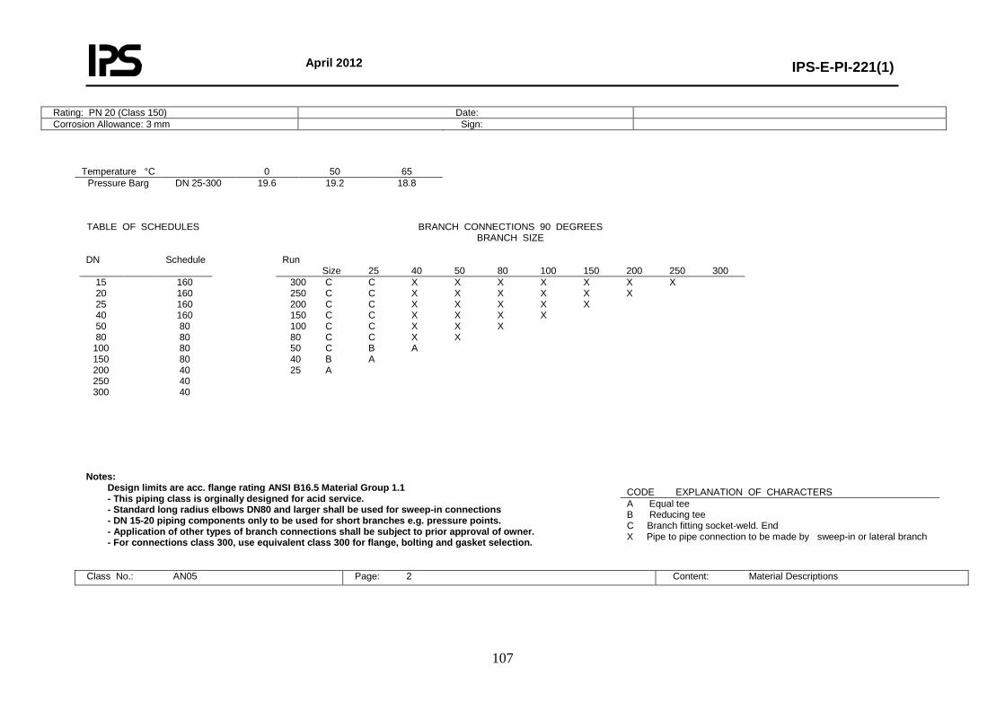
April 2012
IPS-E-PI-221(1)
107
Rating: PN 20 (Class 150) Date: Corrosion Allowance: 3 mm Sign:
Temperature °C 0 50 65 Pressure Barg DN 25-300 19.6 19.2 18.8
Notes:
Design limits are acc. flange rating ANSI B16.5 Material Group 1.1 - This piping class is orginally designed for acid service. - Standard long radius elbows DN80 and larger shall be used for sweep-in connections - DN 15-20 piping components only to be used for short branches e.g. pressure points. - Application of other types of branch connections shall be subject to prior approval of owner. - For connections class 300, use equivalent class 300 for flange, bolting and gasket selection.
Class No.: AN05 Page: 2 Content: Material Descriptions
TABLE OF SCHEDULES BRANCH CONNECTIONS 90 DEGREES BRANCH SIZE
DN Schedule Run
Size 25 40 50 80 100 150 200 250 300 15 20 25 40 50 80
100 150 200 250 300
160 160 160 160 80 80 80 80 40 40 40
300 C C X X X X X X X 250 C C X X X X X X 200 C C X X X X X 150 C C X X X X 100 C C X X X 80 C C X X 50 C B A 40 B A 25 A
CODE EXPLANATION OF CHARACTERS A Equal tee B Reducing tee C Branch fitting socket-weld. End X Pipe to pipe connection to be made by sweep-in or lateral branch
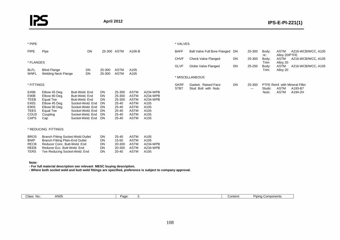
April 2012
IPS-E-PI-221(1)
108
* PIPE PIPE Pipe DN 25-300 ASTM A106-B * FLANGES BLFL Blind Flange DN 25-300 ASTM A105 WNFL Welding Neck Flange DN 25-300 ASTM A105 * FITTINGS E45B Elbow 45 Deg. Butt-Weld. End DN 25-300 ASTM A234-WPB E90B Elbow 90 Deg. Butt-Weld. End DN 25-300 ASTM A234-WPB TEEB Equal Tee Butt-Weld. End DN 25-300 ASTM A234-WPB E45S Elbow 45 Deg. Socket-Weld. End DN 25-40 ASTM A105 E90S Elbow 90 Deg. Socket-Weld. End DN 25-40 ASTM A105 TEES Equal Tee Socket-Weld. End DN 25-40 ASTM A105 COUS Coupling Socket-Weld. End DN 25-40 ASTM A105 CAPS Cap Socket-Weld. End DN 25-40 ASTM A105 * REDUCING FITTINGS BROS Branch Fitting Socket-Weld Outlet DN 25-40 ASTM A105 BNIP Branch Fitting Plain-End Outlet DN 15-50 ASTM A105 RECB Reducer Conc. Butt-Weld. End DN 20-300 ASTM A234-WPB REEB Reducer Ecc. Butt-Weld. End DN 20-300 ASTM A234-WPB TERS Tee Reducing Socket-Weld. End DN 20-40 ASTM A105
* VALVES BAFF Ball Valve Full Bore Flanged DN 25-300 Body: ASTM A216-WCB/WCC, A105 nt.: Alloy 20/PTFE CHVF Check Valve Flanged DN 25-300 Body: ASTM A216-WCB/WCC, A105 Trim: Alloy 20 GLVF Globe Valve Flanged DN 25-200 Body: ASTM A216-WCB/WCC, A105 Trim: Alloy 20 * MISCELLANEOUS GKRF Gasket, Raised Face DN 25-300 PTFE Reinf. with Mineral Filler STBT Stud Bolt with Nuts --- Studs: ASTM A193-B7 Nuts: ASTM A194-2H
Note: - For full material description see relevant MESC buying description. - Where both socket weld and butt weld fittings are specified, preference is subject to company approval.
Class No.: AN05 Page: 3 Content: Piping Components
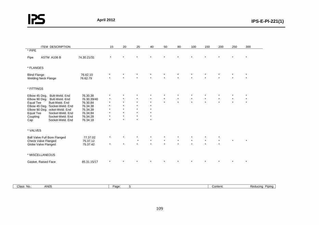
April 2012
IPS-E-PI-221(1)
109
ITEM DESCRIPTION 15 20 25 40 50 80 100 150 200 250 300 * PIPE Pipe ASTM A106 B 74.30.21/31 * * * * * * * * * * * * FLANGES Blind Flange 76.62.10 * * * * * * * * * * * Welding Neck Flange 76.62.79 * * * * * * * * * * * * FITTINGS Elbow 45 Deg. Butt-Weld. End 76.30.38 * * * * * * * * * * * Elbow 90 Deg. Butt-Weld. End 76.30.39/40 * * * * * * * * * * * Equal Tee Butt-Weld. End 76.30.84 * * * * * * * * * * * Elbow 45 Deg. Socket-Weld. End 76.34.38 * * * * Elbow 90 Deg. ocket-Weld. End 76.34.39 * * * * Equal Tee Socket-Weld. End 76.34.84 * * * * Coupling Socket-Weld. End 76.34.28 * * * * Cap Socket-Weld. End 76.34.18 * * * * * VALVES Ball Valve Full Bore Flanged 77.37.02 * * * * * * * * * Check Valve Flanged 75.37.12 * * * * * * * * * Globe Valve Flanged 75.37.42 * * * * * * * * * * MISCELLANEOUS Gasket, Raised Face 85.31.15/17 * * * * * * * * * * *
Class No.: AN05 Page: 5 Content: Reducing Piping
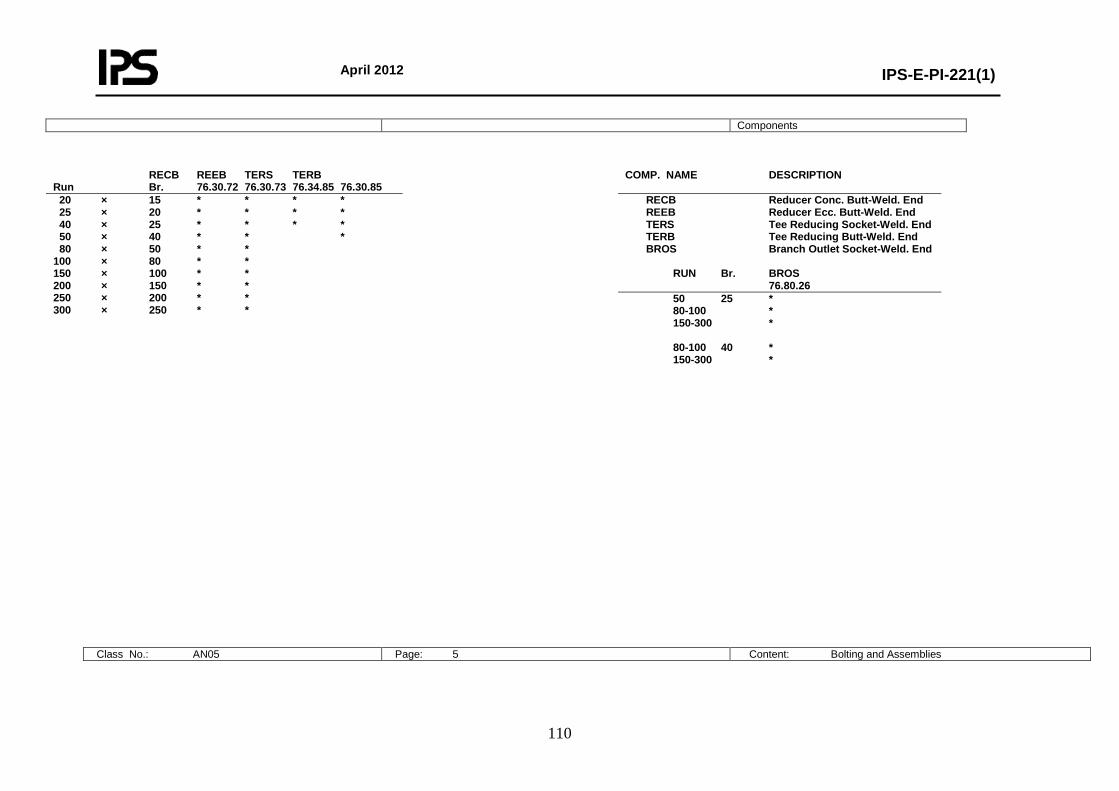
April 2012
IPS-E-PI-221(1)
110
Components
RECB REEB TERS TERB Run Br. 76.30.72 76.30.73 76.34.85 76.30.85
COMP. NAME DESCRIPTION
20 × 15 * * * * 25 × 20 * * * * 40 × 25 * * * * 50 × 40 * * * 80 × 50 * * 100 × 80 * * 150 × 100 * * 200 × 150 * * 250 × 200 * * 300 × 250 * *
RECB Reducer Conc. Butt-Weld. End REEB Reducer Ecc. Butt-Weld. End TERS Tee Reducing Socket-Weld. End TERB Tee Reducing Butt-Weld. End BROS Branch Outlet Socket-Weld. End RUN Br. BROS 76.80.26
50 25 * 80-100 * 150-300 * 80-100 40 * 150-300 *
Class No.: AN05 Page: 5 Content: Bolting and Assemblies
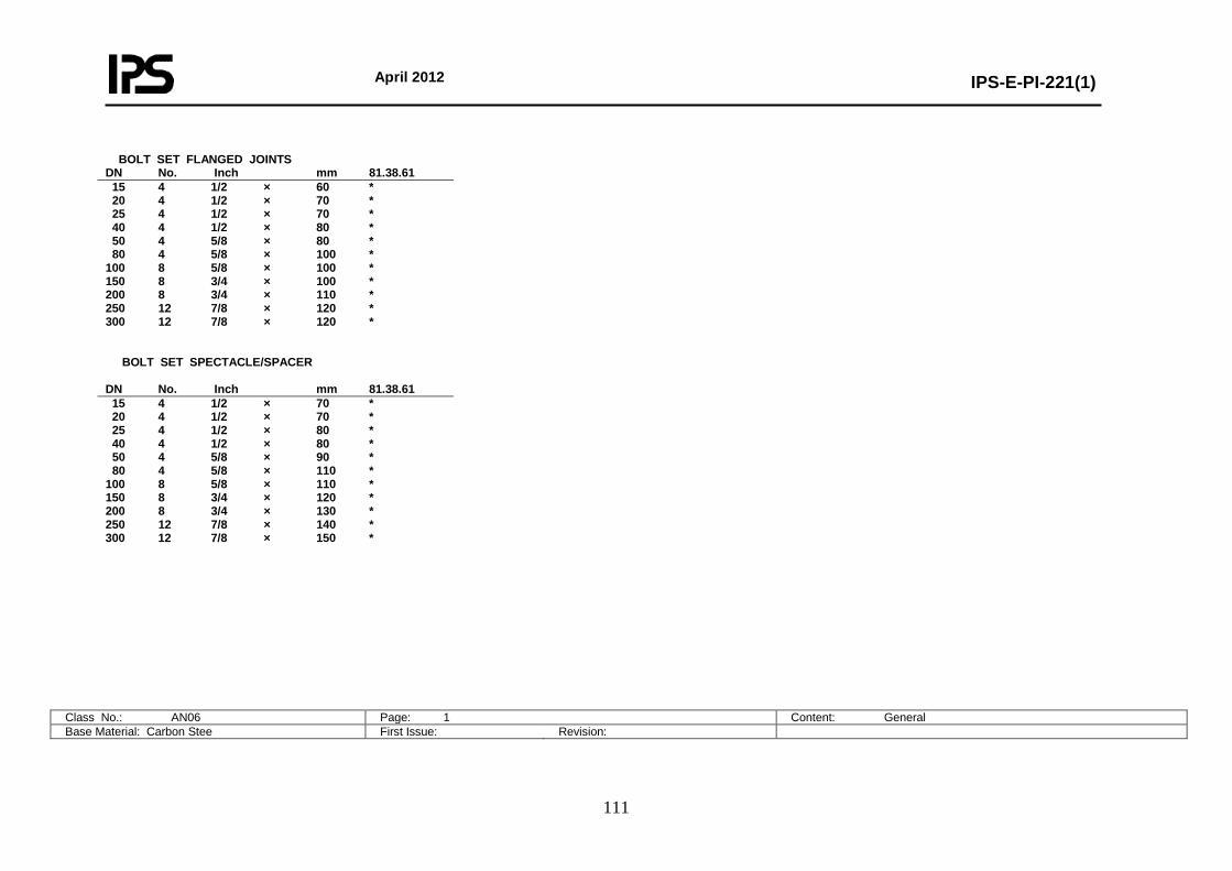
April 2012
IPS-E-PI-221(1)
111
Class No.: AN06 Page: 1 Content: General Base Material: Carbon Stee First Issue: Revision:
BOLT SET FLANGED JOINTS DN No. Inch mm 81.38.61 15 4 1/2 × 60 * 20 4 1/2 × 70 * 25 4 1/2 × 70 * 40 4 1/2 × 80 * 50 4 5/8 × 80 * 80 4 5/8 × 100 * 100 8 5/8 × 100 * 150 8 3/4 × 100 * 200 8 3/4 × 110 * 250 12 7/8 × 120 * 300 12 7/8 × 120 * BOLT SET SPECTACLE/SPACER DN No. Inch mm 81.38.61 15 4 1/2 × 70 * 20 4 1/2 × 70 * 25 4 1/2 × 80 * 40 4 1/2 × 80 * 50 4 5/8 × 90 * 80 4 5/8 × 110 * 100 8 5/8 × 110 * 150 8 3/4 × 120 * 200 8 3/4 × 130 * 250 12 7/8 × 140 * 300 12 7/8 × 150 *
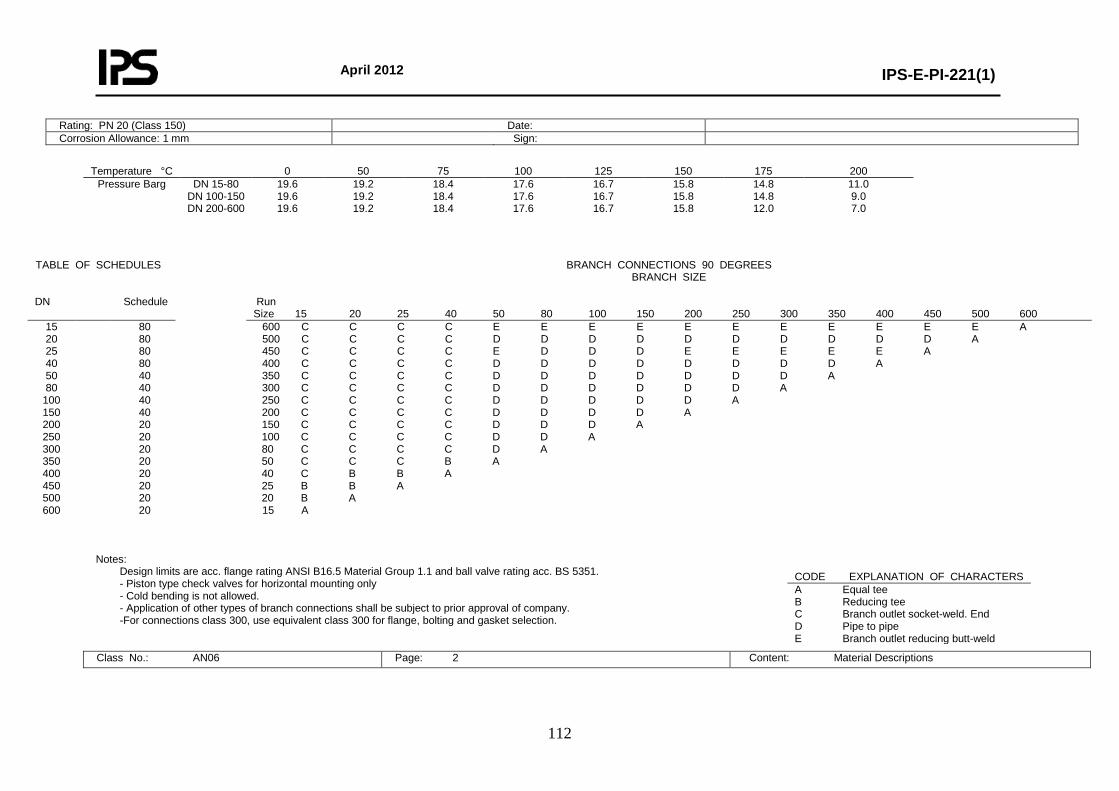
April 2012
IPS-E-PI-221(1)
112
Rating: PN 20 (Class 150) Date: Corrosion Allowance: 1 mm Sign:
Temperature °C 0 50 75 100 125 150 175 200
Pressure Barg DN 15-80 DN 100-150 DN 200-600
19.6 19.6 19.6
19.2 19.2 19.2
18.4 18.4 18.4
17.6 17.6 17.6
16.7 16.7 16.7
15.8 15.8 15.8
14.8 14.8 12.0
11.0 9.0 7.0
Notes:
Design limits are acc. flange rating ANSI B16.5 Material Group 1.1 and ball valve rating acc. BS 5351. - Piston type check valves for horizontal mounting only - Cold bending is not allowed. - Application of other types of branch connections shall be subject to prior approval of company. -For connections class 300, use equivalent class 300 for flange, bolting and gasket selection.
Class No.: AN06 Page: 2 Content: Material Descriptions
TABLE OF SCHEDULES
BRANCH CONNECTIONS 90 DEGREES
BRANCH SIZE
DN Schedule Run Size 15 20 25 40 50 80 100 150 200 250 300 350 400 450 500 600
15 20 25 40 50 80
100 150 200 250 300 350 400 450 500 600
80 80 80 80 40 40 40 40 20 20 20 20 20 20 20 20
600 C C C C E E E E E E E E E E E A 500 C C C C D D D D D D D D D D A 450 C C C C E D D D E E E E E A 400 C C C C D D D D D D D D A 350 C C C C D D D D D D D A 300 C C C C D D D D D D A 250 C C C C D D D D D A 200 C C C C D D D D A 150 C C C C D D D A 100 C C C C D D A 80 C C C C D A 50 C C C B A 40 C B B A 25 B B A 20 B A 15 A
CODE EXPLANATION OF CHARACTERS A Equal tee B Reducing tee C Branch outlet socket-weld. End D Pipe to pipe E Branch outlet reducing butt-weld
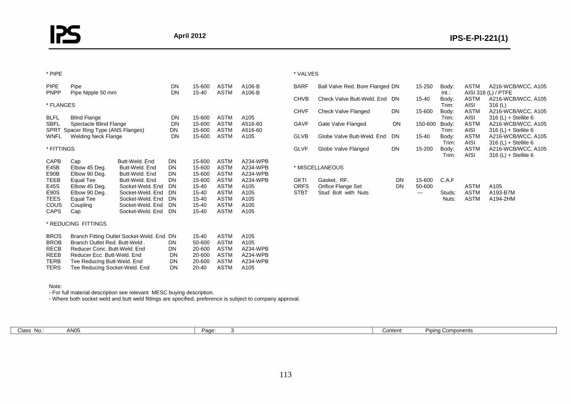
April 2012
IPS-E-PI-221(1)
113
* PIPE PIPE Pipe DN 15-600 ASTM A106-B PNPP Pipe Nipple 50 mm DN 15-40 ASTM A106-B * FLANGES BLFL Blind Flange DN 15-600 ASTM A105 SBFL Spectacle Blind Flange DN 15-600 ASTM A516-60 SPRT Spacer Ring Type (ANS Flanges) DN 15-600 ASTM A516-60 WNFL Welding Neck Flange DN 15-600 ASTM A105 * FITTINGS CAPB Cap Butt-Weld. End DN 15-600 ASTM A234-WPB E45B Elbow 45 Deg. Butt-Weld. End DN 15-600 ASTM A234-WPB E90B Elbow 90 Deg. Butt-Weld. End DN 15-600 ASTM A234-WPB TEEB Equal Tee Butt-Weld. End DN 15-600 ASTM A234-WPB E45S Elbow 45 Deg. Socket-Weld. End DN 15-40 ASTM A105 E90S Elbow 90 Deg. Socket-Weld. End DN 15-40 ASTM A105 TEES Equal Tee Socket-Weld. End DN 15-40 ASTM A105 COUS Coupling Socket-Weld. End DN 15-40 ASTM A105 CAPS Cap Socket-Weld. End DN 15-40 ASTM A105 * REDUCING FITTINGS BROS Branch Fitting Outlet Socket-Weld. End DN 15-40 ASTM A105 BROB Branch Outlet Red. Butt-Weld . DN 50-600 ASTM A105 RECB Reducer Conc. Butt-Weld. End DN 20-600 ASTM A234-WPB REEB Reducer Ecc. Butt-Weld. End DN 20-600 ASTM A234-WPB TERB Tee Reducing Butt-Weld. End DN 20-600 ASTM A234-WPB TERS Tee Reducing Socket-Weld. End DN 20-40 ASTM A105
* VALVES BARF Ball Valve Red. Bore Flanged DN 15-250 Body: ASTM A216-WCB/WCC, A105 Int.: AISI 316 (L) / PTFE CHVB Check Valve Butt-Weld. End DN 15-40 Body: ASTM A216-WCB/WCC, A105 Trim: AISI 316 (L) CHVF Check Valve Flanged DN 15-600 Body: ASTM A216-WCB/WCC, A105 Trim: AISI 316 (L) + Stellite 6 GAVF Gate Valve Flanged DN 150-600 Body: ASTM A216-WCB/WCC, A105 Trim: AISI 316 (L) + Stellite 6 GLVB Globe Valve Butt-Weld. End DN 15-40 Body: ASTM A216-WCB/WCC, A105 Trim: AISI 316 (L) + Stellite 6 GLVF Globe Valve Flanged DN 15-200 Body: ASTM A216-WCB/WCC, A105 Trim: AISI 316 (L) + Stellite 6 * MISCELLANEOUS GKTI Gasket, RF. DN 15-600 C.A.F ORFS Orifice Flange Set DN 50-600 ASTM A105 STBT Stud Bolt with Nuts --- Studs: ASTM A193-B7M Nuts: ASTM A194-2HM
Note: - For full material description see relevant MESC buying description. - Where both socket weld and butt weld fittings are specified, preference is subject to company approval.
Class No.: AN05 Page: 3 Content: Piping Components
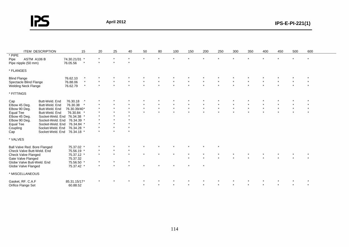
April 2012
IPS-E-PI-221(1)
114
ITEM DESCRIPTION 15 20 25 40 50 80 100 150 200 250 300 350 400 450 500 600 * PIPE Pipe ASTM A106 B 74.30.21/31 * * * * * * * * * * * * * * * * Pipe nipple (50 mm) 76.05.56 * * * * * FLANGES Blind Flange 76.62.10 * * * * * * * * * * * * * * * * Spectacle Blind Flange 76.88.06 * * * * * * * * * * * * * * * * Welding Neck Flange 76.62.79 * * * * * * * * * * * * * * * * * FITTINGS Cap Butt-Weld. End 76.30.18 * * * * * * * * * * * * * * * * Elbow 45 Deg. Butt-Weld. End 76.30.38 * * * * * * * * * * * * * * * * Elbow 90 Deg. Butt-Weld. End 76.30.39/40 * * * * * * * * * * * * * * * * Equal Tee Butt-Weld. End 76.30.84 * * * * * * * * * * * * * * * * Elbow 45 Deg. Socket-Weld. End 76.34.38 * * * * Elbow 90 Deg. Socket-Weld. End 76.34.39 * * * * Equal Tee Socket-Weld. End 76.34.84 * * * * Coupling Socket-Weld. End 76.34.28 * * * * Cap Socket-Weld. End 76.34.18 * * * * * VALVES Ball Valve Red. Bore Flanged 75.37.02 * * * * * * * * * * Check Valve Butt-Weld. End 75.56.19 * * * * Check Valve Flanged 75.37.12 * * * * * * * * * * * * * * * * Gate Valve Flanged 75.37.32 * * * * * * * * * Globe Valve Butt-Weld. End 75.56.50 * * * * Globe Valve Flanged 75.37.42 * * * * * * * * * * MISCELLANEOUS Gasket, RF. C.A.F 85.31.15/17 * * * * * * * * * * * * * * * * Orifice Flange Set 60.88.52 * * * * * * * * * * * *
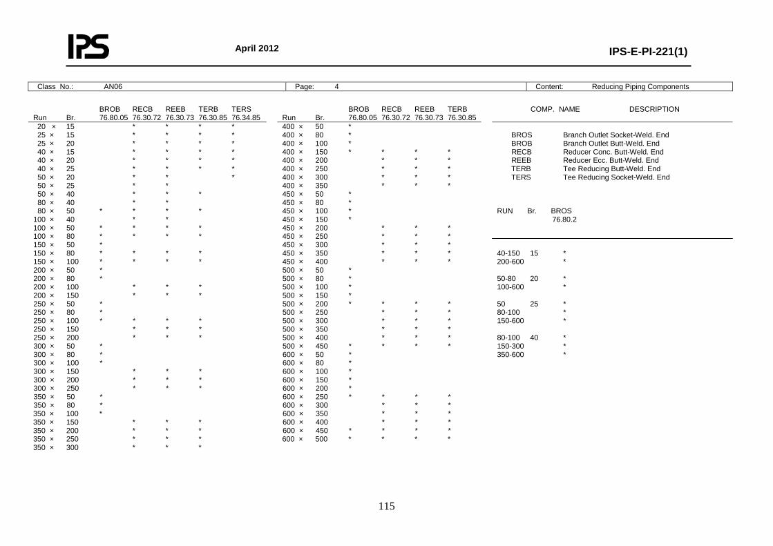
April 2012
IPS-E-PI-221(1)
115
Class No.: AN06 Page: 4 Content: Reducing Piping Components
BROB RECB REEB TERB TERS Run Br. 76.80.05 76.30.72 76.30.73 76.30.85 76.34.85
BROB RECB REEB TERB Run Br. 76.80.05 76.30.72 76.30.73 76.30.85
COMP. NAME DESCRIPTION
20 × 15 * * * * 25 × 15 * * * * 25 × 20 * * * * 40 × 15 * * * * 40 × 20 * * * * 40 × 25 * * * * 50 × 20 * * * 50 × 25 * * 50 × 40 * * * 80 × 40 * * 80 × 50 * * * * 100 × 40 * * 100 × 50 * * * * 100 × 80 * * * * 150 × 50 * 150 × 80 * * * * 150 × 100 * * * * 200 × 50 * 200 × 80 * 200 × 100 * * * 200 × 150 * * * 250 × 50 * 250 × 80 * 250 × 100 * * * * 250 × 150 * * * 250 × 200 * * * 300 × 50 * 300 × 80 * 300 × 100 * 300 × 150 * * * 300 × 200 * * * 300 × 250 * * * 350 × 50 * 350 × 80 * 350 × 100 * 350 × 150 * * * 350 × 200 * * * 350 × 250 * * * 350 × 300 * * *
400 × 50 * 400 × 80 * 400 × 100 * 400 × 150 * * * * 400 × 200 * * * 400 × 250 * * * 400 × 300 * * * 400 × 350 * * * 450 × 50 * 450 × 80 * 450 × 100 * 450 × 150 * 450 × 200 * * * 450 × 250 * * * 450 × 300 * * * 450 × 350 * * * 450 × 400 * * * 500 × 50 * 500 × 80 * 500 × 100 * 500 × 150 * 500 × 200 * * * * 500 × 250 * * * 500 × 300 * * * 500 × 350 * * * 500 × 400 * * * 500 × 450 * * * * 600 × 50 * 600 × 80 * 600 × 100 * 600 × 150 * 600 × 200 * 600 × 250 * * * * 600 × 300 * * * 600 × 350 * * * 600 × 400 * * * 600 × 450 * * * * 600 × 500 * * * *
BROS Branch Outlet Socket-Weld. End BROB Branch Outlet Butt-Weld. End RECB Reducer Conc. Butt-Weld. End REEB Reducer Ecc. Butt-Weld. End TERB Tee Reducing Butt-Weld. End TERS Tee Reducing Socket-Weld. End RUN Br. BROS 76.80.2 40-150 15 * 200-600 * 50-80 20 * 100-600 * 50 25 * 80-100 * 150-600 * 80-100 40 * 150-300 * 350-600 *
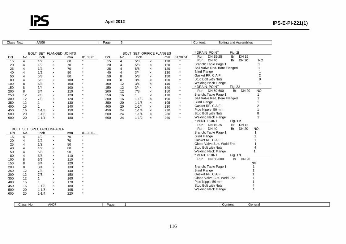
April 2012
IPS-E-PI-221(1)
116
Class No.: AN06 Page: 5 Content: Bolting and Assemblies
* DRAIN POINT Fig. 2I Run DN 15-25 Br DN 15 Run DN 40 Br DN 20 NO Branch: Table Page 1 1 Ball Valve Red. Bore Flanged 1 Blind Flange 1 Gasket RF. C.A.F. 2 Stud Bolt with Nuts 8 Welding Neck Flange 1 * DRAIN POINT Fig. 2J Run DN 50-600 Br DN 20 NO. Branch: Table Page 1 1 Ball Valve Red. Bore Flanged 1 Blind Flange 1 Gasket RF. C.A.F. 2 Pipe Nipple 50 mm 1 Stud Bolt with Nuts 8 Welding Neck Flange 1 * VENT POINT Fig. 1M Run DN 15-25 Br DN 15 Run DN 40 Br DN 20 NO. Branch: Table Page 1 1 Blind Flange 1 Gasket RF. C.A.F. 1 Globe Valve Butt. Weld End 1 Stud Bolt with Nuts 4 Welding Neck Flange 1 * VENT POINT Fig. 1N Run DN 50-600 Br DN 20 No. Branch: Table Page 1 1 Blind Flange 1 Gasket RF. C.A.F. 1 Globe Valve Butt. Weld End 1 Pipe Nipple 50 mm 1 Stud Bolt with Nuts 4 Welding Neck Flange 1
Class No.: AN07 Page: 1 Content: General
BOLT SET FLANGED JOINTS DN No. Inch mm 81.38.61
BOLT SET ORIFICE FLANGES DN No. Inch mm 81.38.61
15 4 1/2 × 60 * 20 4 1/2 × 70 * 25 4 1/2 × 70 * 40 4 1/2 × 80 * 50 4 5/8 × 80 * 80 4 5/8 × 100 * 100 8 5/8 × 100 * 150 8 3/4 × 100 * 200 8 3/4 × 110 * 250 12 7/8 × 120 * 300 12 7/8 × 120 * 350 12 1 × 130 * 400 16 1 × 140 * 450 16 1-1/8 × 150 * 500 20 1-1/8 × 160 * 600 20 1-1/4 × 180 * BOLT SET SPECTACLE/SPACER
15 4 5/8 × 120 * 20 4 5/8 × 120 * 25 4 5/8 × 120 * 40 4 3/4 × 130 * 50 8 5/8 × 150 * 80 8 3/4 × 150 * 100 12 3/4 × 140 * 150 12 3/4 × 140 * 200 12 7/8 × 150 * 250 16 1 × 170 * 300 16 1-1/8 × 190 * 350 20 1-1/8 × 195 * 400 20 1-1/4 × 210 * 450 24 1-1/4 × 220 * 500 24 1-1/4 × 230 * 600 24 1-1/2 × 260 *
DN No. Inch mm 81.38.61 15 4 1/2 × 70 * 20 4 1/2 × 70 * 25 4 1/2 × 80 * 40 4 1/2 × 80 * 50 4 5/8 × 90 * 80 4 5/8 × 110 * 100 8 5/8 × 110 * 150 8 3/4 × 120 * 200 8 3/4 × 130 * 250 12 7/8 × 140 * 300 12 7/8 × 150 * 350 12 1 × 160 * 400 16 1 × 170 * 450 16 1-1/8 × 180 * 500 20 1-1/8 × 195 * 600 20 1-1/4 × 220 *
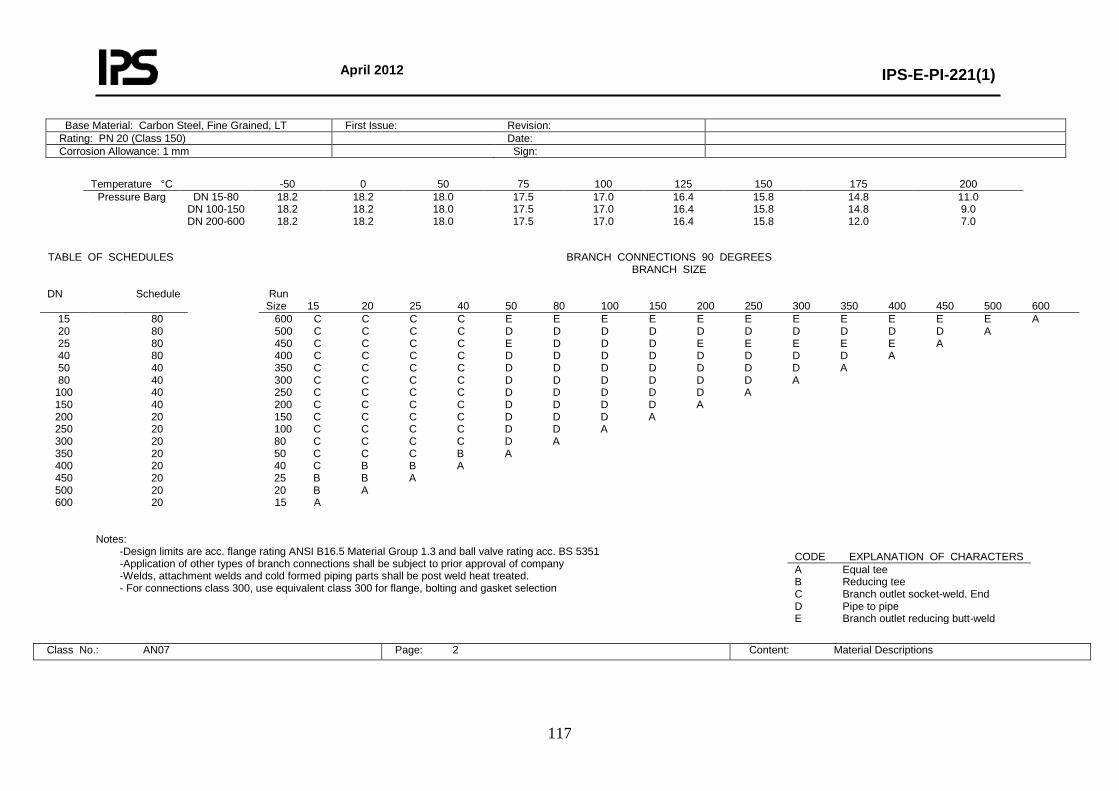
April 2012
IPS-E-PI-221(1)
117
Base Material: Carbon Steel, Fine Grained, LT First Issue: Revision: Rating: PN 20 (Class 150) Date: Corrosion Allowance: 1 mm Sign:
Temperature °C -50 0 50 75 100 125 150 175 200
Pressure Barg DN 15-80 DN 100-150 DN 200-600
18.2 18.2 18.2
18.2 18.2 18.2
18.0 18.0 18.0
17.5 17.5 17.5
17.0 17.0 17.0
16.4 16.4 16.4
15.8 15.8 15.8
14.8 14.8 12.0
11.0 9.0 7.0
Notes:
-Design limits are acc. flange rating ANSI B16.5 Material Group 1.3 and ball valve rating acc. BS 5351 -Application of other types of branch connections shall be subject to prior approval of company -Welds, attachment welds and cold formed piping parts shall be post weld heat treated. - For connections class 300, use equivalent class 300 for flange, bolting and gasket selection
Class No.: AN07 Page: 2 Content: Material Descriptions
TABLE OF SCHEDULES BRANCH CONNECTIONS 90 DEGREES BRANCH SIZE
DN Schedule Run
Size 15 20 25 40 50 80 100 150 200 250 300 350 400 450 500 600 15 20 25 40 50 80
100 150 200 250 300 350 400 450 500 600
80 80 80 80 40 40 40 40 20 20 20 20 20 20 20 20
600 C C C C E E E E E E E E E E E A 500 C C C C D D D D D D D D D D A 450 C C C C E D D D E E E E E A 400 C C C C D D D D D D D D A 350 C C C C D D D D D D D A 300 C C C C D D D D D D A 250 C C C C D D D D D A 200 C C C C D D D D A 150 C C C C D D D A 100 C C C C D D A 80 C C C C D A 50 C C C B A 40 C B B A 25 B B A 20 B A 15 A
CODE EXPLANATION OF CHARACTERS A Equal tee B Reducing tee C Branch outlet socket-weld. End D Pipe to pipe E Branch outlet reducing butt-weld
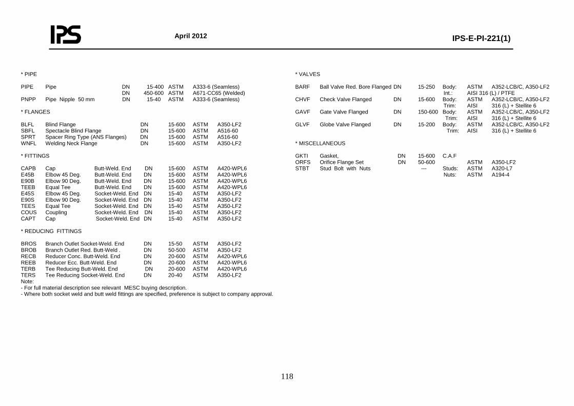
April 2012
IPS-E-PI-221(1)
118
* PIPE PIPE Pipe DN 15-400 ASTM A333-6 (Seamless) DN 450-600 ASTM A671-CC65 (Welded) PNPP Pipe Nipple 50 mm DN 15-40 ASTM A333-6 (Seamless) * FLANGES BLFL Blind Flange DN 15-600 ASTM A350-LF2 SBFL Spectacle Blind Flange DN 15-600 ASTM A516-60 SPRT Spacer Ring Type (ANS Flanges) DN 15-600 ASTM A516-60 WNFL Welding Neck Flange DN 15-600 ASTM A350-LF2 * FITTINGS CAPB Cap Butt-Weld. End DN 15-600 ASTM A420-WPL6 E45B Elbow 45 Deg. Butt-Weld. End DN 15-600 ASTM A420-WPL6 E90B Elbow 90 Deg. Butt-Weld. End DN 15-600 ASTM A420-WPL6 TEEB Equal Tee Butt-Weld. End DN 15-600 ASTM A420-WPL6 E45S Elbow 45 Deg. Socket-Weld. End DN 15-40 ASTM A350-LF2 E90S Elbow 90 Deg. Socket-Weld. End DN 15-40 ASTM A350-LF2 TEES Equal Tee Socket-Weld. End DN 15-40 ASTM A350-LF2 COUS Coupling Socket-Weld. End DN 15-40 ASTM A350-LF2 CAPT Cap Socket-Weld. End DN 15-40 ASTM A350-LF2 * REDUCING FITTINGS BROS Branch Outlet Socket-Weld. End DN 15-50 ASTM A350-LF2 BROB Branch Outlet Red. Butt-Weld . DN 50-500 ASTM A350-LF2 RECB Reducer Conc. Butt-Weld. End DN 20-600 ASTM A420-WPL6 REEB Reducer Ecc. Butt-Weld. End DN 20-600 ASTM A420-WPL6 TERB Tee Reducing Butt-Weld. End DN 20-600 ASTM A420-WPL6 TERS Tee Reducing Socket-Weld. End DN 20-40 ASTM A350-LF2 Note: - For full material description see relevant MESC buying description. - Where both socket weld and butt weld fittings are specified, preference is subject to company approval.
* VALVES BARF Ball Valve Red. Bore Flanged DN 15-250 Body: ASTM A352-LCB/C, A350-LF2 Int.: AISI 316 (L) / PTFE CHVF Check Valve Flanged DN 15-600 Body: ASTM A352-LCB/C, A350-LF2 Trim: AISI 316 (L) + Stellite 6 GAVF Gate Valve Flanged DN 150-600 Body: ASTM A352-LCB/C, A350-LF2 Trim: AISI 316 (L) + Stellite 6 GLVF Globe Valve Flanged DN 15-200 Body: ASTM A352-LCB/C, A350-LF2 Trim: AISI 316 (L) + Stellite 6 * MISCELLANEOUS GKTI Gasket, DN 15-600 C.A.F ORFS Orifice Flange Set DN 50-600 ASTM A350-LF2 STBT Stud Bolt with Nuts --- Studs: ASTM A320-L7 Nuts: ASTM A194-4
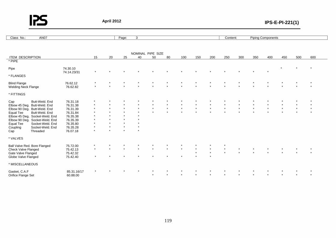
April 2012
IPS-E-PI-221(1)
119
Class No.: AN07 Page: 3 Content: Piping Components
NOMINAL PIPE SIZE ITEM DESCRIPTION 15 20 25 40 50 80 100 150 200 250 300 350 400 450 500 600 * PIPE Pipe 74.30.10 * * * 74.14.23/31 * * * * * * * * * * * * * * FLANGES Blind Flange 76.62.12 * * * * * * * * * * * * * * * * Welding Neck Flange 76.62.82 * * * * * * * * * * * * * * * * * FITTINGS Cap Butt-Weld. End 76.31.18 * * * * * * * * * * * * * * * * Elbow 45 Deg. Butt-Weld. End 76.31.38 * * * * * * * * * * * * * * * * Elbow 90 Deg. Butt-Weld. End 76.31.39 * * * * * * * * * * * * * * * * Equal Tee Butt-Weld. End 76.31.84 * * * * * * * * * * * * * * * * Elbow 45 Deg. Socket-Weld. End 76.35.38 * * * * Elbow 90 Deg. Socket-Weld. End 76.35.39 * * * * Equal Tee Socket-Weld. End 76.35.80 * * * * Coupling Socket-Weld. End 76.35.28 * * * * Cap Threaded 76.07.18 * * * * * VALVES Ball Valve Red. Bore Flanged 75.72.00 * * * * * * * * * * Check Valve Flanged 75.42.13 * * * * * * * * * * * * * * * * Gate Valve Flanged 75.42.32 * * * * * * * * * Globe Valve Flanged 75.42.40 * * * * * * * * * * MISCELLANEOUS Gasket, C.A.F 85.31.16/17 * * * * * * * * * * * * * * * * Orifice Flange Set 60.88.00 * * * * * * * * * * * *
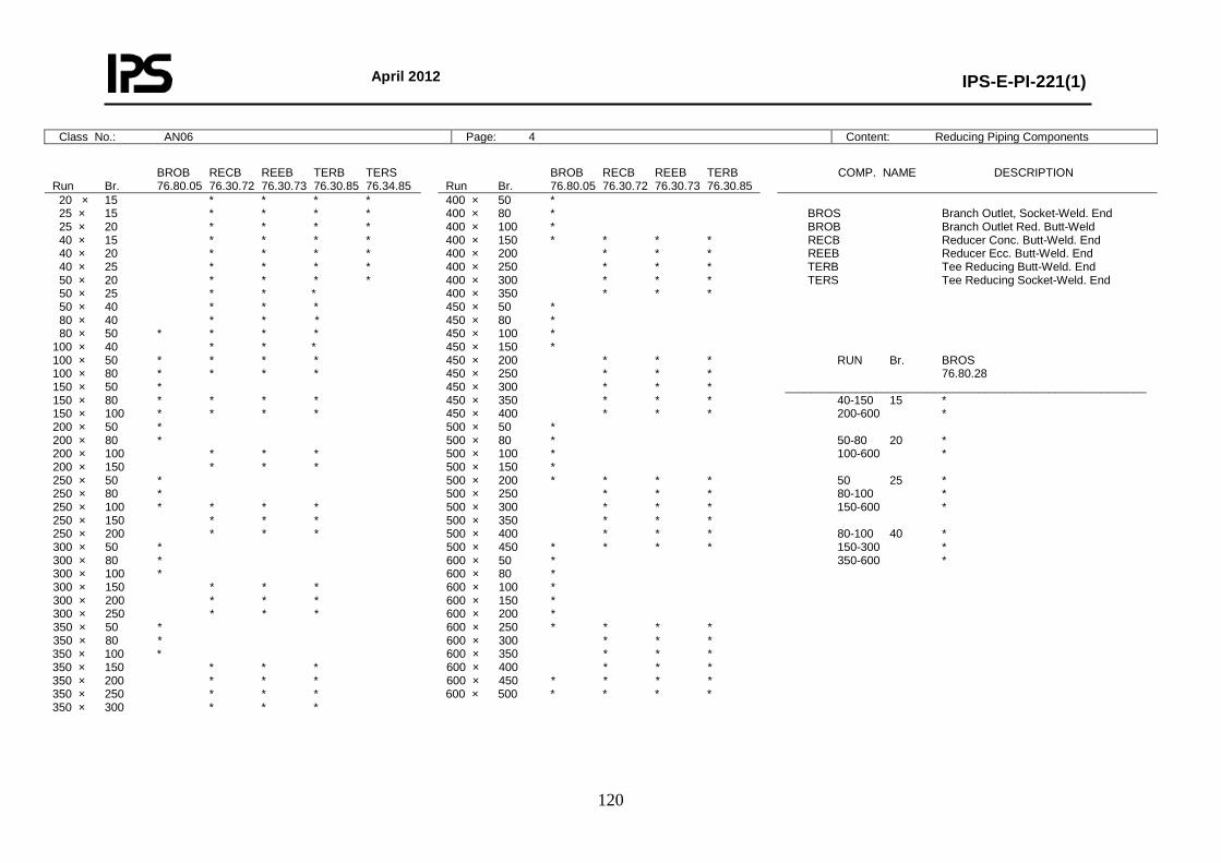
April 2012
IPS-E-PI-221(1)
120
Class No.: AN06 Page: 4 Content: Reducing Piping Components
BROB RECB REEB TERB TERS Run Br. 76.80.05 76.30.72 76.30.73 76.30.85 76.34.85
BROB RECB REEB TERB Run Br. 76.80.05 76.30.72 76.30.73 76.30.85
COMP. NAME DESCRIPTION
20 × 15 * * * * 25 × 15 * * * * 25 × 20 * * * * 40 × 15 * * * * 40 × 20 * * * * 40 × 25 * * * * 50 × 20 * * * * 50 × 25 * * * 50 × 40 * * * 80 × 40 * * * 80 × 50 * * * * 100 × 40 * * * 100 × 50 * * * * 100 × 80 * * * * 150 × 50 * 150 × 80 * * * * 150 × 100 * * * * 200 × 50 * 200 × 80 * 200 × 100 * * * 200 × 150 * * * 250 × 50 * 250 × 80 * 250 × 100 * * * * 250 × 150 * * * 250 × 200 * * * 300 × 50 * 300 × 80 * 300 × 100 * 300 × 150 * * * 300 × 200 * * * 300 × 250 * * * 350 × 50 * 350 × 80 * 350 × 100 * 350 × 150 * * * 350 × 200 * * * 350 × 250 * * * 350 × 300 * * *
400 × 50 * 400 × 80 * 400 × 100 * 400 × 150 * * * * 400 × 200 * * * 400 × 250 * * * 400 × 300 * * * 400 × 350 * * * 450 × 50 * 450 × 80 * 450 × 100 * 450 × 150 * 450 × 200 * * * 450 × 250 * * * 450 × 300 * * * 450 × 350 * * * 450 × 400 * * * 500 × 50 * 500 × 80 * 500 × 100 * 500 × 150 * 500 × 200 * * * * 500 × 250 * * * 500 × 300 * * * 500 × 350 * * * 500 × 400 * * * 500 × 450 * * * * 600 × 50 * 600 × 80 * 600 × 100 * 600 × 150 * 600 × 200 * 600 × 250 * * * * 600 × 300 * * * 600 × 350 * * * 600 × 400 * * * 600 × 450 * * * * 600 × 500 * * * *
BROS Branch Outlet, Socket-Weld. End BROB Branch Outlet Red. Butt-Weld RECB Reducer Conc. Butt-Weld. End REEB Reducer Ecc. Butt-Weld. End TERB Tee Reducing Butt-Weld. End TERS Tee Reducing Socket-Weld. End RUN Br. BROS 76.80.28 ________________________________________________________ 40-150 15 * 200-600 * 50-80 20 * 100-600 * 50 25 * 80-100 * 150-600 * 80-100 40 * 150-300 * 350-600 *
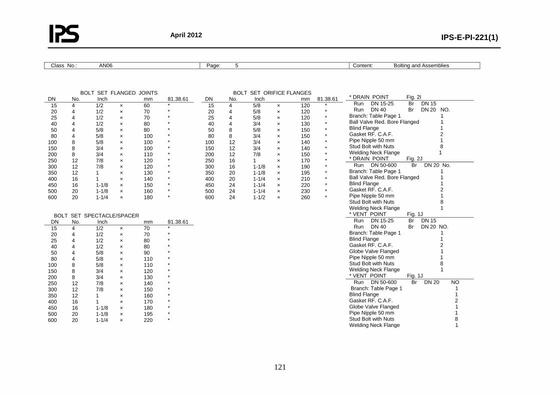
April 2012
IPS-E-PI-221(1)
121
Class No.: AN06 Page: 5 Content: Bolting and Assemblies
BOLT SET FLANGED JOINTS DN No. Inch mm 81.38.61
BOLT SET ORIFICE FLANGES DN No. Inch mm 81.38.61
15 4 1/2 × 60 * 20 4 1/2 × 70 * 25 4 1/2 × 70 * 40 4 1/2 × 80 * 50 4 5/8 × 80 * 80 4 5/8 × 100 * 100 8 5/8 × 100 * 150 8 3/4 × 100 * 200 8 3/4 × 110 * 250 12 7/8 × 120 * 300 12 7/8 × 120 * 350 12 1 × 130 * 400 16 1 × 140 * 450 16 1-1/8 × 150 * 500 20 1-1/8 × 160 * 600 20 1-1/4 × 180 * BOLT SET SPECTACLE/SPACER
15 4 5/8 × 120 * 20 4 5/8 × 120 * 25 4 5/8 × 120 * 40 4 3/4 × 130 * 50 8 5/8 × 150 * 80 8 3/4 × 150 * 100 12 3/4 × 140 * 150 12 3/4 × 140 * 200 12 7/8 × 150 * 250 16 1 × 170 * 300 16 1-1/8 × 190 * 350 20 1-1/8 × 195 * 400 20 1-1/4 × 210 * 450 24 1-1/4 × 220 * 500 24 1-1/4 × 230 * 600 24 1-1/2 × 260 *
DN No. Inch mm 81.38.61 15 4 1/2 × 70 * 20 4 1/2 × 70 * 25 4 1/2 × 80 * 40 4 1/2 × 80 * 50 4 5/8 × 90 * 80 4 5/8 × 110 * 100 8 5/8 × 110 * 150 8 3/4 × 120 * 200 8 3/4 × 130 * 250 12 7/8 × 140 * 300 12 7/8 × 150 * 350 12 1 × 160 * 400 16 1 × 170 * 450 16 1-1/8 × 180 * 500 20 1-1/8 × 195 * 600 20 1-1/4 × 220 *
* DRAIN POINT Fig. 2I Run DN 15-25 Br DN 15 Run DN 40 Br DN 20 NO. Branch: Table Page 1 1 Ball Valve Red. Bore Flanged 1 Blind Flange 1 Gasket RF. C.A.F. 2 Pipe Nipple 50 mm 1 Stud Bolt with Nuts 8 Welding Neck Flange 1 * DRAIN POINT Fig. 2J Run DN 50-600 Br DN 20 No. Branch: Table Page 1 1 Ball Valve Red. Bore Flanged 1 Blind Flange 1 Gasket RF. C.A.F. 2 Pipe Nipple 50 mm 1 Stud Bolt with Nuts 8 Welding Neck Flange 1 * VENT POINT Fig. 1J Run DN 15-25 Br DN 15 Run DN 40 Br DN 20 NO. Branch: Table Page 1 1 Blind Flange 1 Gasket RF. C.A.F. 2 Globe Valve Flanged 1 Pipe Nipple 50 mm 1 Stud Bolt with Nuts 8 Welding Neck Flange 1 * VENT POINT Fig. 1J Run DN 50-600 Br DN 20 NO Branch: Table Page 1 1 Blind Flange 1 Gasket RF. C.A.F. 2 Globe Valve Flanged 1 Pipe Nipple 50 mm 1 Stud Bolt with Nuts 8 Welding Neck Flange 1
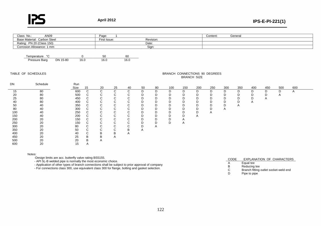
April 2012
IPS-E-PI-221(1)
122
Class No.: AN09 Page: 1 Content: General Base Material: Carbon Steel First Issue: Revision: Rating: PN 20 (Class 150) Date: Corrosion Allowance: 1 mm Sign:
Temperature °C 0 50 60
Pressure Barg DN 15-80
16.0 16.0 16.0
Notes:
-Design limits are acc. butterfly valve rating BS5155. - API 5L-B welded pipe is normally the most economic choice. - Application of other types of branch connections shall be subject to prior approval of company - For connections class 300, use equivalent class 300 for flange, bolting and gasket selection.
TABLE OF SCHEDULES BRANCH CONNECTIONS 90 DEGREES BRANCH SIZE
DN Schedule Run
Size 15 20 25 40 50 80 100 150 200 250 300 350 400 450 500 600 15 20 25 40 50 80
100 150 200 250 300 350 400 450 500 600
80 80 80 80 40 40 40 40 20 20 20 20 20 20 20 20
600 C C C C D D D D D D D D D D D A 500 C C C C D D D D D D D D D D A 450 C C C C D D D D D D D D D A 400 C C C C D D D D D D D D A 350 C C C C D D D D D D D A 300 C C C C D D D D D D A 250 C C C C D D D D D A 200 C C C C D D D D A 150 C C C C D D D A 150 C C C C D D D A 80 C C C C D A 50 C C C B A 40 C B B A 25 B B A 20 B A 15 A
CODE EXPLANATION OF CHARACTERS A Equal tee B Reducing tee C Branch fitting outlet socket-weld end D Pipe to pipe
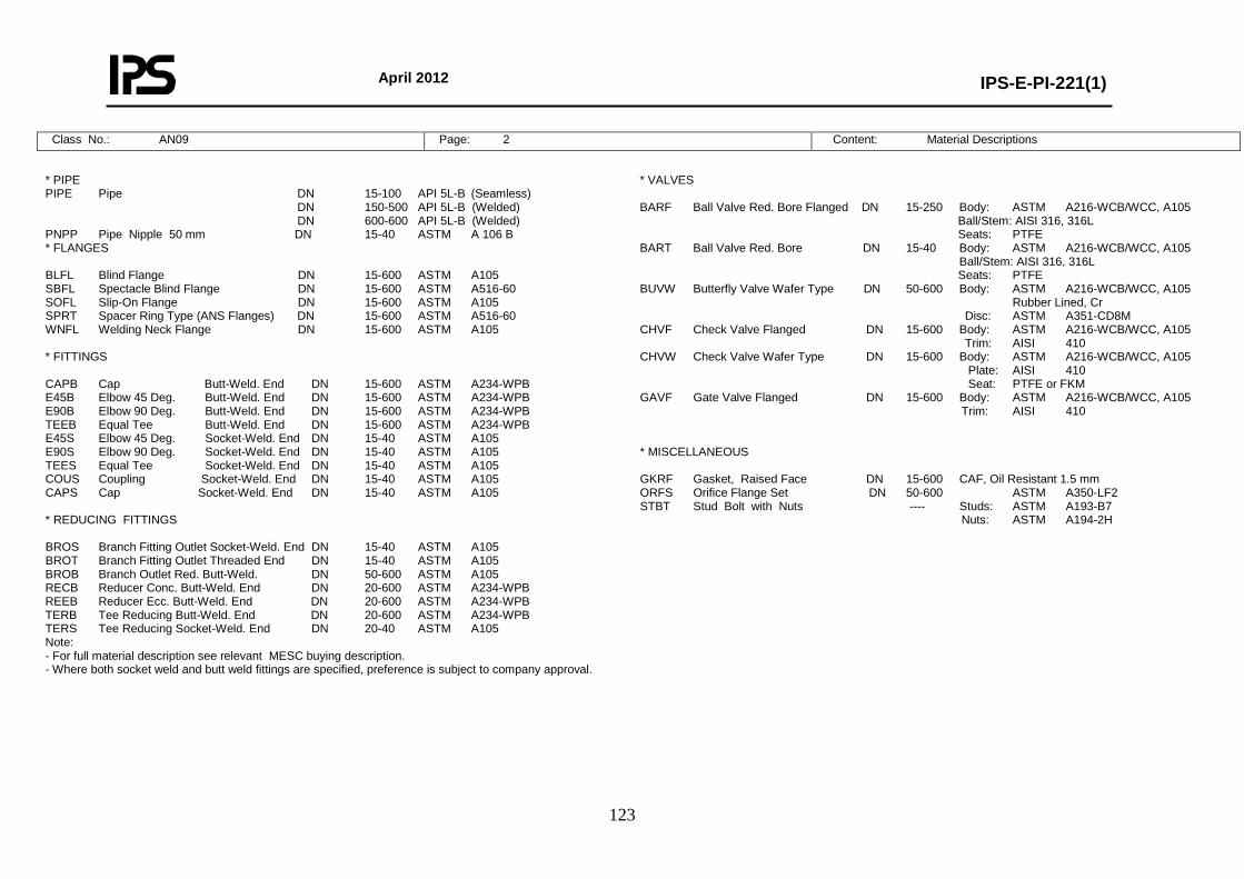
April 2012
IPS-E-PI-221(1)
123
Class No.: AN09 Page: 2 Content: Material Descriptions
* PIPE PIPE Pipe DN 15-100 API 5L-B (Seamless) DN 150-500 API 5L-B (Welded) DN 600-600 API 5L-B (Welded) PNPP Pipe Nipple 50 mm DN 15-40 ASTM A 106 B * FLANGES BLFL Blind Flange DN 15-600 ASTM A105 SBFL Spectacle Blind Flange DN 15-600 ASTM A516-60 SOFL Slip-On Flange DN 15-600 ASTM A105 SPRT Spacer Ring Type (ANS Flanges) DN 15-600 ASTM A516-60 WNFL Welding Neck Flange DN 15-600 ASTM A105 * FITTINGS CAPB Cap Butt-Weld. End DN 15-600 ASTM A234-WPB E45B Elbow 45 Deg. Butt-Weld. End DN 15-600 ASTM A234-WPB E90B Elbow 90 Deg. Butt-Weld. End DN 15-600 ASTM A234-WPB TEEB Equal Tee Butt-Weld. End DN 15-600 ASTM A234-WPB E45S Elbow 45 Deg. Socket-Weld. End DN 15-40 ASTM A105 E90S Elbow 90 Deg. Socket-Weld. End DN 15-40 ASTM A105 TEES Equal Tee Socket-Weld. End DN 15-40 ASTM A105 COUS Coupling Socket-Weld. End DN 15-40 ASTM A105 CAPS Cap Socket-Weld. End DN 15-40 ASTM A105 * REDUCING FITTINGS BROS Branch Fitting Outlet Socket-Weld. End DN 15-40 ASTM A105 BROT Branch Fitting Outlet Threaded End DN 15-40 ASTM A105 BROB Branch Outlet Red. Butt-Weld. DN 50-600 ASTM A105 RECB Reducer Conc. Butt-Weld. End DN 20-600 ASTM A234-WPB REEB Reducer Ecc. Butt-Weld. End DN 20-600 ASTM A234-WPB TERB Tee Reducing Butt-Weld. End DN 20-600 ASTM A234-WPB TERS Tee Reducing Socket-Weld. End DN 20-40 ASTM A105 Note: - For full material description see relevant MESC buying description. - Where both socket weld and butt weld fittings are specified, preference is subject to company approval.
* VALVES BARF Ball Valve Red. Bore Flanged DN 15-250 Body: ASTM A216-WCB/WCC, A105 Ball/Stem: AISI 316, 316L Seats: PTFE BART Ball Valve Red. Bore DN 15-40 Body: ASTM A216-WCB/WCC, A105 Ball/Stem: AISI 316, 316L Seats: PTFE BUVW Butterfly Valve Wafer Type DN 50-600 Body: ASTM A216-WCB/WCC, A105 Rubber Lined, Cr Disc: ASTM A351-CD8M CHVF Check Valve Flanged DN 15-600 Body: ASTM A216-WCB/WCC, A105 Trim: AISI 410 CHVW Check Valve Wafer Type DN 15-600 Body: ASTM A216-WCB/WCC, A105 Plate: AISI 410 Seat: PTFE or FKM GAVF Gate Valve Flanged DN 15-600 Body: ASTM A216-WCB/WCC, A105 Trim: AISI 410 * MISCELLANEOUS GKRF Gasket, Raised Face DN 15-600 CAF, Oil Resistant 1.5 mm ORFS Orifice Flange Set DN 50-600 ASTM A350-LF2 STBT Stud Bolt with Nuts ---- Studs: ASTM A193-B7 Nuts: ASTM A194-2H
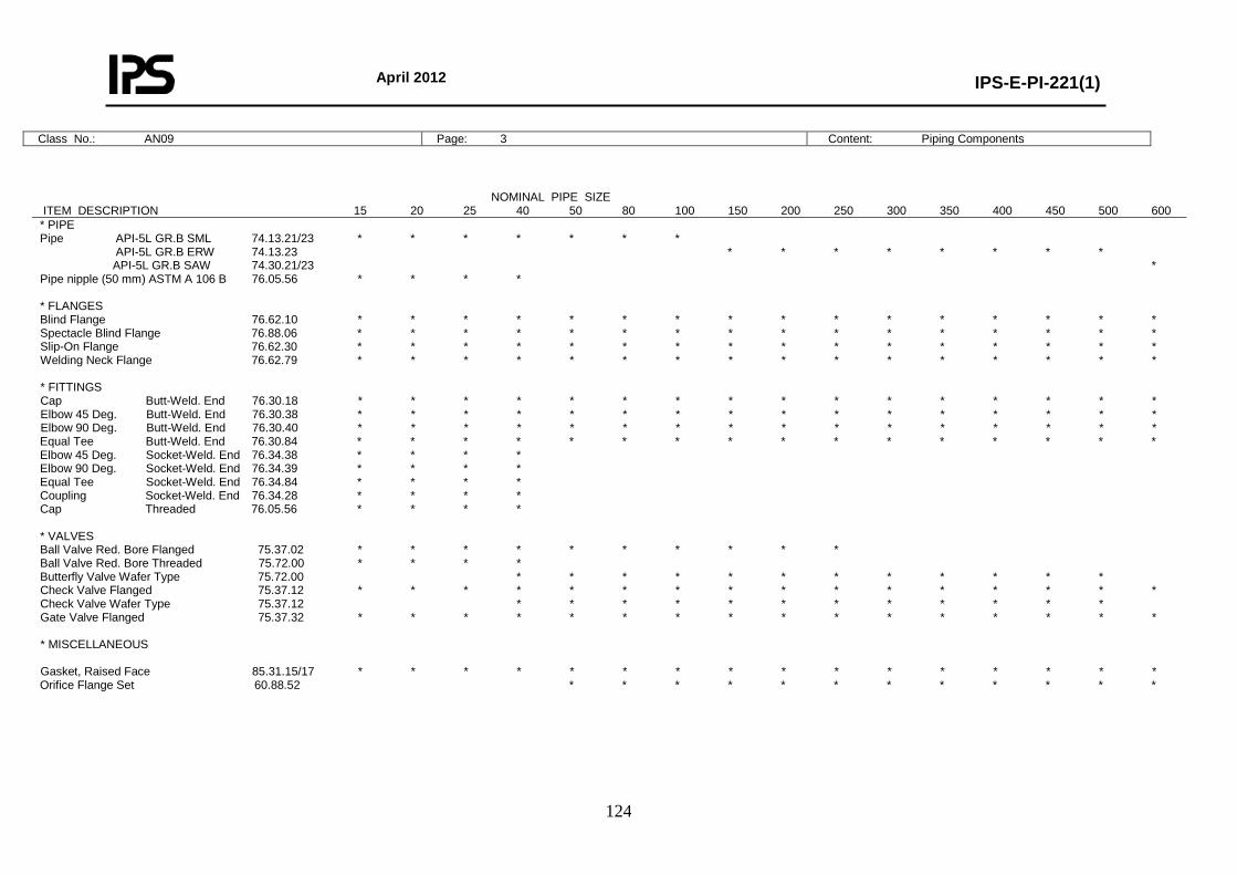
April 2012
IPS-E-PI-221(1)
124
Class No.: AN09 Page: 3 Content: Piping Components
NOMINAL PIPE SIZE ITEM DESCRIPTION 15 20 25 40 50 80 100 150 200 250 300 350 400 450 500 600 * PIPE Pipe API-5L GR.B SML 74.13.21/23 * * * * * * * API-5L GR.B ERW 74.13.23 * * * * * * * * API-5L GR.B SAW 74.30.21/23 * Pipe nipple (50 mm) ASTM A 106 B 76.05.56 * * * * * FLANGES Blind Flange 76.62.10 * * * * * * * * * * * * * * * * Spectacle Blind Flange 76.88.06 * * * * * * * * * * * * * * * * Slip-On Flange 76.62.30 * * * * * * * * * * * * * * * * Welding Neck Flange 76.62.79 * * * * * * * * * * * * * * * * * FITTINGS Cap Butt-Weld. End 76.30.18 * * * * * * * * * * * * * * * * Elbow 45 Deg. Butt-Weld. End 76.30.38 * * * * * * * * * * * * * * * * Elbow 90 Deg. Butt-Weld. End 76.30.40 * * * * * * * * * * * * * * * * Equal Tee Butt-Weld. End 76.30.84 * * * * * * * * * * * * * * * * Elbow 45 Deg. Socket-Weld. End 76.34.38 * * * * Elbow 90 Deg. Socket-Weld. End 76.34.39 * * * * Equal Tee Socket-Weld. End 76.34.84 * * * * Coupling Socket-Weld. End 76.34.28 * * * * Cap Threaded 76.05.56 * * * * * VALVES Ball Valve Red. Bore Flanged 75.37.02 * * * * * * * * * * Ball Valve Red. Bore Threaded 75.72.00 * * * * Butterfly Valve Wafer Type 75.72.00 * * * * * * * * * * * * Check Valve Flanged 75.37.12 * * * * * * * * * * * * * * * * Check Valve Wafer Type 75.37.12 * * * * * * * * * * * * Gate Valve Flanged 75.37.32 * * * * * * * * * * * * * * * * * MISCELLANEOUS Gasket, Raised Face 85.31.15/17 * * * * * * * * * * * * * * * * Orifice Flange Set 60.88.52 * * * * * * * * * * * *
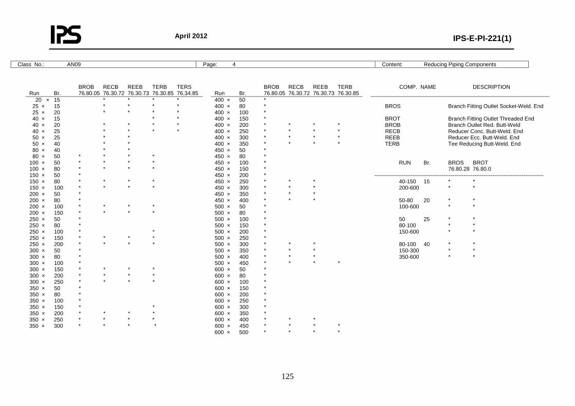
April 2012
IPS-E-PI-221(1)
125
Class No.: AN09 Page: 4 Content: Reducing Piping Components
BROB RECB REEB TERB TERS Run Br. 76.80.05 76.30.72 76.30.73 76.30.85 76.34.85
BROB RECB REEB TERB Run Br. 76.80.05 76.30.72 76.30.73 76.30.85
COMP. NAME DESCRIPTION
20 × 15 * * * * 25 × 15 * * * * 25 × 20 * * * * 40 × 15 * * 40 × 20 * * * * 40 × 25 * * * * 50 × 25 * * 50 × 40 * * 80 × 40 * * 80 × 50 * * * * 100 × 50 * * * * 100 × 80 * * * * 150 × 50 * 150 × 80 * * * * 150 × 100 * * * * 200 × 50 * 200 × 80 * 200 × 100 * * * * 200 × 150 * * * * 250 × 50 * 250 × 80 * 250 × 100 * * 250 × 150 * * * * 250 × 200 * * * * 300 × 50 * 300 × 80 * 300 × 100 * 300 × 150 * * * * 300 × 200 * * * * 300 × 250 * * * * 350 × 50 * 350 × 80 * 350 × 100 * 350 × 150 * * 350 × 200 * * * * 350 × 250 * * * * 350 × 300 * * * *
400 × 50 * 400 × 80 * 400 × 100 * 400 × 150 * 400 × 200 * * * * 400 × 250 * * * * 400 × 300 * * * * 400 × 350 * * * * 450 × 50 * 450 × 80 * 450 × 100 * 450 × 150 * 450 × 200 * 450 × 250 * * * 450 × 300 * * * 450 × 350 * * * 450 × 400 * * * 500 × 50 * 500 × 80 * 500 × 100 * 500 × 150 * 500 × 200 * 500 × 250 * 500 × 300 * * * 500 × 350 * * * 500 × 400 * * * 500 × 450 * * * * 600 × 50 * 600 × 80 * 600 × 100 * 600 × 150 * 600 × 200 * 600 × 250 * 600 × 300 * 600 × 350 * 600 × 400 * * * 600 × 450 * * * * 600 × 500 * * * *
BROS Branch Fitting Outlet Socket-Weld. End BROT Branch Fitting Outlet Threaded End BROB Branch Outlet Red. Butt-Weld RECB Reducer Conc. Butt-Weld. End REEB Reducer Ecc. Butt-Weld. End TERB Tee Reducing Butt-Weld. End RUN Br. BROS BROT 76.80.28 76.80.0 --------------------------------------------------------------------------------------------- 40-150 15 * * 200-600 * * 50-80 20 * * 100-600 * * 50 25 * * 80-100 * * 150-600 * * 80-100 40 * * 150-300 * * 350-600 * *
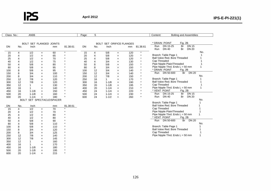
April 2012
IPS-E-PI-221(1)
126
Class No.: AN06 Page: 5 Content: Bolting and Assemblies
* DRAIN POINT Fig. 2B Run DN 15-25 Br DN 15 Run DN 40 Br DN 20 No. Branch: Table Page 1 1 Ball Valve Red. Bore Threaded 1 Cap Threaded 1 Pipe Nipple Plain/Threaded 1 Pipe Nipple Thrd. Ends L = 50 mm 1 * DRAIN POINT Fig. 2B Run DN 50-600 Br DN 20 No. Branch: Table Page 1 1 Ball Valve Red. Bore Threaded 1 Cap Threaded 1 Pipe Nipple Thrd. Ends L = 50 mm 1 * VENT POINT Fig. 2B Run DN 15-25 Br DN 15 Run DN 40 Br DN 20 No. Branch: Table Page 1 1 Ball Valve Red. Bore Threaded 1 Cap Threaded 1 Pipe Nipple Plain/Threaded 1 Pipe Nipple Thrd. Ends L = 50 mm 1 * VENT POINT Fig. 2B Run DN 50-600 Br DN 20 No. Branch: Table Page 1 1 Ball Valve Red. Bore Threaded 1 Cap Threaded 1 Pipe Nipple Thrd. Ends L = 50 mm 1
BOLT SET FLANGED JOINTS DN No. Inch mm 81.38.61
BOLT SET ORIFICE FLANGES DN No. Inch mm 81.38.61
15 4 1/2 × 60 * 20 4 1/2 × 65 * 25 4 1/2 × 70 * 40 4 1/2 × 75 * 50 4 5/8 × 80 * 80 4 5/8 × 95 * 100 8 5/8 × 95 * 150 8 3/4 × 100 * 200 8 3/4 × 110 * 250 12 7/8 × 120 * 300 12 7/8 × 120 * 350 12 1 × 130 * 400 16 1 × 140 * 450 16 1-1/8 × 150 * 500 20 1-1/8 × 160 * 600 20 1-1/4 × 180 *
15 4 5/8 × 120 * 20 4 5/8 × 120 * 25 4 5/8 × 120 * 40 4 3/4 × 130 * 50 8 5/8 × 150 * 80 8 3/4 × 150 * 100 12 3/4 × 140 * 150 12 3/4 × 140 * 200 12 7/8 × 150 * 250 16 1 × 170 * 300 16 1-1/8 × 190 * 350 20 1-1/8 × 195 * 400 20 1-1/4 × 210 * 450 24 1-1/4 × 220 * 500 24 1-1/4 × 230 * 600 24 1-1/2 × 260 *
BOLT SET SPECTACLE/SPACER DN No. Inch mm 81.38.61 15 4 1/2 × 70 * 20 4 1/2 × 70 * 25 4 1/2 × 80 * 40 4 1/2 × 80 * 50 4 5/8 × 90 * 80 4 5/8 × 110 * 100 8 5/8 × 110 * 150 8 3/4 × 120 * 200 8 3/4 × 125 * 250 12 7/8 × 140 * 300 12 7/8 × 145 * 350 12 1 × 160 * 400 16 1 × 170 * 450 16 1-1/8 × 180 * 500 20 1-1/8 × 195 * 600 20 1-1/4 × 215 *
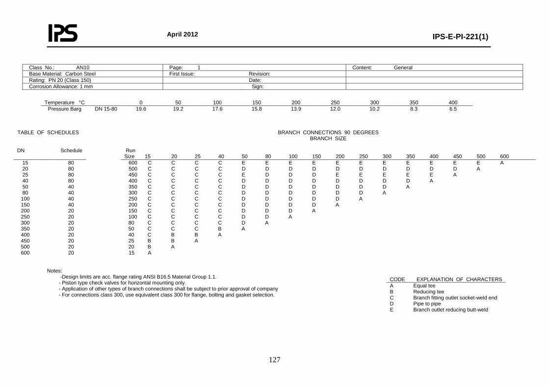
April 2012
IPS-E-PI-221(1)
127
Class No.: AN10 Page: 1 Content: General Base Material: Carbon Steel First Issue: Revision: Rating: PN 20 (Class 150) Date: Corrosion Allowance: 1 mm Sign:
Temperature °C 0 50 100 150 200 250 300 350 400
Pressure Barg DN 15-80
19.6 19.2 17.6 15.8 13.9 12.0 10.2 8.3 6.5
Notes:
-Design limits are acc. flange rating ANSI B16.5 Material Group 1.1. - Piston type check valves for horizontal mounting only. - Application of other types of branch connections shall be subject to prior approval of company - For connections class 300, use equivalent class 300 for flange, bolting and gasket selection.
TABLE OF SCHEDULES BRANCH CONNECTIONS 90 DEGREES BRANCH SIZE
DN Schedule Run
Size 15 20 25 40 50 80 100 150 200 250 300 350 400 450 500 600 15 20 25 40 50 80
100 150 200 250 300 350 400 450 500 600
80 80 80 80 40 40 40 40 20 20 20 20 20 20 20 20
600 C C C C E E E E E E E E E E E A 500 C C C C D D D D D D D D D D A 450 C C C C E D D D E E E E E A 400 C C C C D D D D D D D D A 350 C C C C D D D D D D D A 300 C C C C D D D D D D A 250 C C C C D D D D D A 200 C C C C D D D D A 150 C C C C D D D A 100 C C C C D D A 80 C C C C D A 50 C C C B A 40 C B B A 25 B B A 20 B A 15 A
CODE EXPLANATION OF CHARACTERS A Equal tee B Reducing tee C Branch fitting outlet socket-weld end D Pipe to pipe E Branch outlet reducing butt-weld
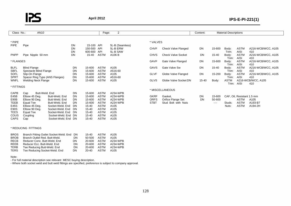
April 2012
IPS-E-PI-221(1)
128
Class No.: AN10 Page: 2 Content: Material Descriptions
* PIPE PIPE Pipe DN 15-100 API 5L-B (Seamless) DN 150-500 API 5L-B ERW DN 600-600 API 5L-B SAW PNPP Pipe Nipple 50 mm DN 15-40 ASTM A106 B * FLANGES BLFL Blind Flange DN 15-600 ASTM A105 SBFL Spectacle Blind Flange DN 15-600 ASTM A516-60 SOFL Slip-On Flange DN 15-600 ASTM A105 SPRT Spacer Ring Type (ANS Flanges) DN 15-600 ASTM A516-60 WNFL Welding Neck Flange DN 15-600 ASTM A105 * FITTINGS CAPB Cap Butt-Weld. End DN 15-600 ASTM A234-WPB E45B Elbow 45 Deg. Butt-Weld. End DN 15-600 ASTM A234-WPB E90B Elbow 90 Deg. Butt-Weld. End DN 15-600 ASTM A234-WPB TEEB Equal Tee Butt-Weld. End DN 15-600 ASTM A234-WPB E45S Elbow 45 Deg. Socket-Weld. End DN 15-40 ASTM A105 E90S Elbow 90 Deg. Socket-Weld. End DN 15-40 ASTM A105 TEES Equal Tee Socket-Weld. End DN 15-40 ASTM A105 COUS Coupling Socket-Weld. End DN 15-40 ASTM A105 CAPS Cap Socket-Weld. End DN 15-40 ASTM A105 * REDUCING FITTINGS BROS Branch Fitting Outlet Socket-Weld. End DN 15-40 ASTM A105 BROB Branch Outlet Red. Butt-Weld. DN 50-500 ASTM A105 RECB Reducer Conc. Butt-Weld. End DN 20-600 ASTM A234-WPB REEB Reducer Ecc. Butt-Weld. End DN 20-600 ASTM A234-WPB TERB Tee Reducing Butt-Weld. End DN 20-600 ASTM A234-WPB TERS Tee Reducing Socket-Weld. End DN 20-40 ASTM A105 Note: - For full material description see relevant MESC buying description. - Where both socket weld and butt weld fittings are specified, preference is subject to company approval.
* VALVES CHVF Check Valve Flanged DN 15-600 Body: ASTM A216-WCB/WCC, A105 Trim: AISI 410 CHVS Check Valve Socket DN 15-40 Body: ASTM A216-WCB/WCC, A105 Trim: AISI 410 GAVF Gate Valve Flanged DN 15-600 Body: ASTM A216-WCB/WCC, A105 Trim: AISI 410 GAVS Gate Valve Sw DN 15-40 Body: ASTM A216-WCB/WCC, A105 Trim: AISI 410 GLVF Globe Valve Flanged DN 15-200 Body: ASTM A216-WCB/WCC, A105 Trim: AISI 410 GLVS Globe Valve Socket DN 15-40 Body: ASTM A216-WCB/WCC, A105 Trim: AISI 410 * MISCELLANEOUS GKRF Gasket, DN 15-600 CAF, Oil, Resistant 1.5 mm ORFS Orifice Flange Set DN 50-600 ASTM A105 STBT Stud Bolt with Nuts ---- Studs: ASTM A193-B7 Nuts: ASTM A194-2H
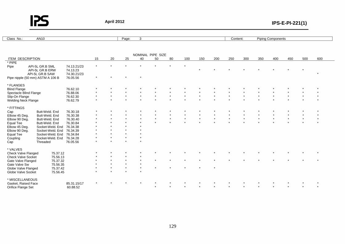
April 2012
IPS-E-PI-221(1)
129
Class No.: AN10 Page: 3 Content: Piping Components
NOMINAL PIPE SIZE ITEM DESCRIPTION 15 20 25 40 50 80 100 150 200 250 300 350 400 450 500 600 * PIPE Pipe API-5L GR.B SML 74.13.21/23 * * * * * * * API-5L GR.B ERW 74.13.23 * * * * * * * * API-5L GR.B SAW 74.30.21/23 * Pipe nipple (50 mm) ASTM A 106 B 76.05.56 * * * * * FLANGES Blind Flange 76.62.10 * * * * * * * * * * * * * * * * Spectacle Blind Flange 76.88.06 * * * * * * * * * * * * * * * * Slip-On Flange 76.62.30 * * * * * * * * * * * * * * * * Welding Neck Flange 76.62.79 * * * * * * * * * * * * * * * * * FITTINGS Cap Butt-Weld. End 76.30.18 * * * * * * * * * * * * * * * * Elbow 45 Deg. Butt-Weld. End 76.30.38 * * * * * * * * * * * * * * * * Elbow 90 Deg. Butt-Weld. End 76.30.40 * * * * * * * * * * * * * * * * Equal Tee Butt-Weld. End 76.30.84 * * * * * * * * * * * * * * * * Elbow 45 Deg. Socket-Weld. End 76.34.38 * * * * Elbow 90 Deg. Socket-Weld. End 76.34.39 * * * * Equal Tee Socket-Weld. End 76.34.84 * * * * Coupling Socket-Weld. End 76.34.28 * * * * Cap Threaded 76.05.56 * * * * * VALVES Check Valve Flanged 75.37.12 * * * * * * * * * * * * * * * * Check Valve Socket 75.56.13 * * * * Gate Valve Flanged 75.37.32 * * * * * * * * * * * * * * * * Gate Valve Sw 75.56.35 * * * * Globe Valve Flanged 75.37.42 * * * * * * * * * Globe Valve Socket 75.56.45 * * * * * MISCELLANEOUS Gasket, Raised Face 85.31.15/17 * * * * * * * * * * * * * * * * Orifice Flange Set 60.88.52 * * * * * * * * * * * *
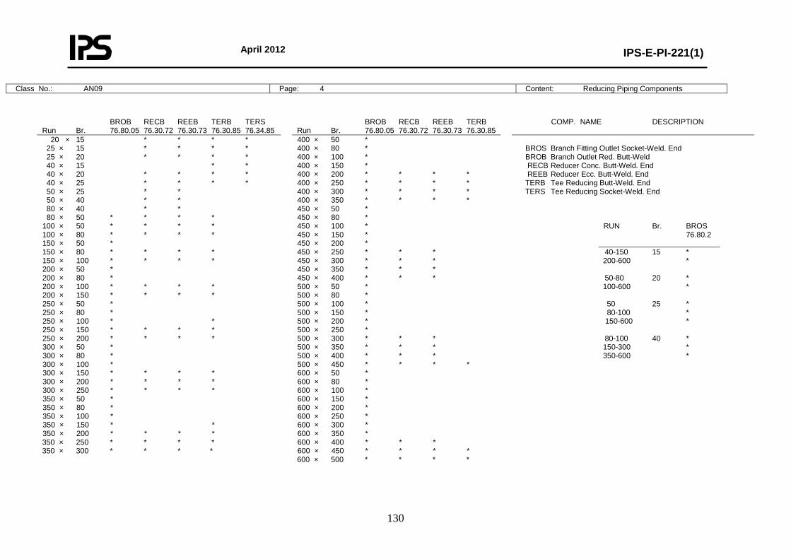
April 2012
IPS-E-PI-221(1)
130
Class No.: AN09 Page: 4 Content: Reducing Piping Components
BROB RECB REEB TERB TERS Run Br. 76.80.05 76.30.72 76.30.73 76.30.85 76.34.85
BROB RECB REEB TERB Run Br. 76.80.05 76.30.72 76.30.73 76.30.85
COMP. NAME DESCRIPTION
20 × 15 * * * * 25 × 15 * * * * 25 × 20 * * * * 40 × 15 * * 40 × 20 * * * * 40 × 25 * * * * 50 × 25 * * 50 × 40 * * 80 × 40 * * 80 × 50 * * * * 100 × 50 * * * * 100 × 80 * * * * 150 × 50 * 150 × 80 * * * * 150 × 100 * * * * 200 × 50 * 200 × 80 * 200 × 100 * * * * 200 × 150 * * * * 250 × 50 * 250 × 80 * 250 × 100 * * 250 × 150 * * * * 250 × 200 * * * * 300 × 50 * 300 × 80 * 300 × 100 * 300 × 150 * * * * 300 × 200 * * * * 300 × 250 * * * * 350 × 50 * 350 × 80 * 350 × 100 * 350 × 150 * * 350 × 200 * * * * 350 × 250 * * * * 350 × 300 * * * *
400 × 50 * 400 × 80 * 400 × 100 * 400 × 150 * 400 × 200 * * * * 400 × 250 * * * * 400 × 300 * * * * 400 × 350 * * * * 450 × 50 * 450 × 80 * 450 × 100 * 450 × 150 * 450 × 200 * 450 × 250 * * * 450 × 300 * * * 450 × 350 * * * 450 × 400 * * * 500 × 50 * 500 × 80 * 500 × 100 * 500 × 150 * 500 × 200 * 500 × 250 * 500 × 300 * * * 500 × 350 * * * 500 × 400 * * * 500 × 450 * * * * 600 × 50 * 600 × 80 * 600 × 100 * 600 × 150 * 600 × 200 * 600 × 250 * 600 × 300 * 600 × 350 * 600 × 400 * * * 600 × 450 * * * * 600 × 500 * * * *
BROS Branch Fitting Outlet Socket-Weld. End BROB Branch Outlet Red. Butt-Weld RECB Reducer Conc. Butt-Weld. End REEB Reducer Ecc. Butt-Weld. End TERB Tee Reducing Butt-Weld. End TERS Tee Reducing Socket-Weld. End RUN Br. BROS 76.80.2 _____________________________ 40-150 15 * 200-600 * 50-80 20 * 100-600 * 50 25 * 80-100 * 150-600 * 80-100 40 * 150-300 * 350-600 *
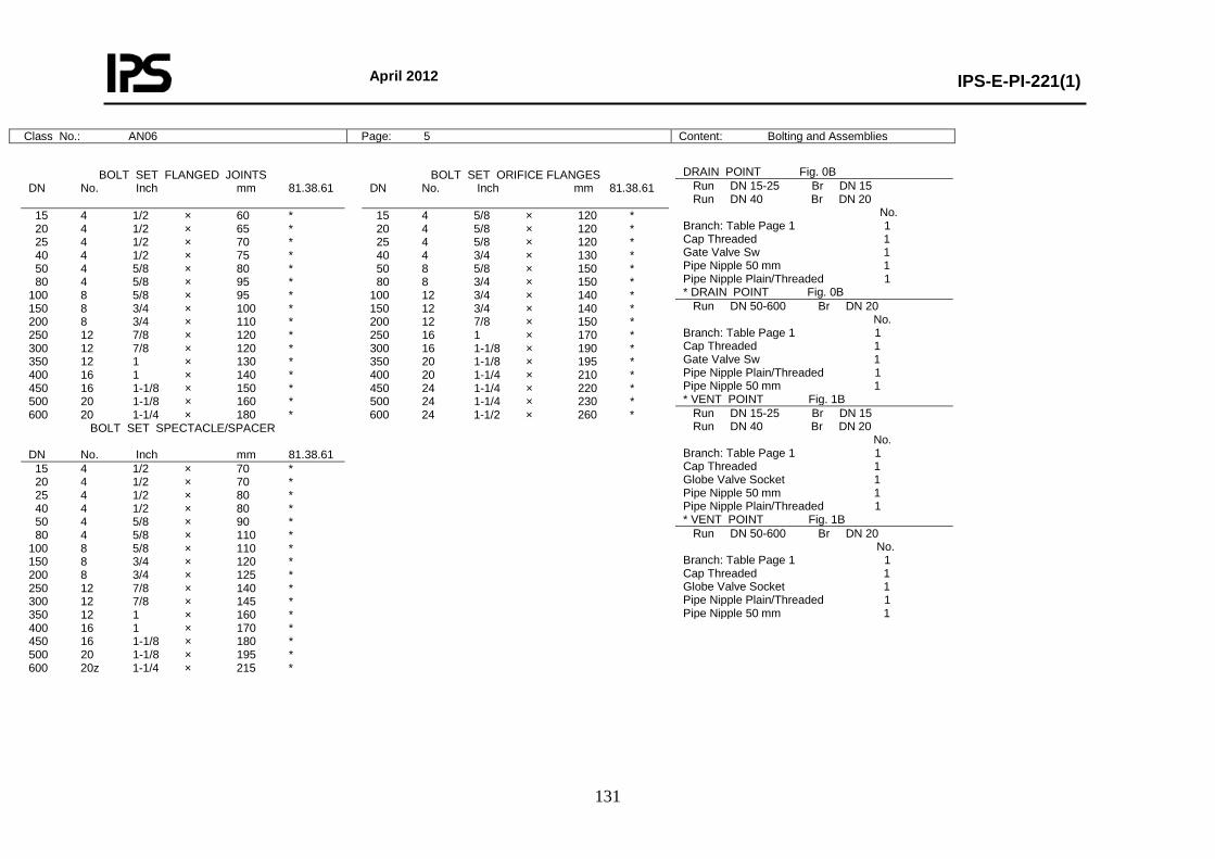
April 2012
IPS-E-PI-221(1)
131
Class No.: AN06 Page: 5 Content: Bolting and Assemblies
DRAIN POINT Fig. 0B Run DN 15-25 Br DN 15 Run DN 40 Br DN 20 No. Branch: Table Page 1 1 Cap Threaded 1 Gate Valve Sw 1 Pipe Nipple 50 mm 1 Pipe Nipple Plain/Threaded 1 * DRAIN POINT Fig. 0B Run DN 50-600 Br DN 20 No. Branch: Table Page 1 1 Cap Threaded 1 Gate Valve Sw 1 Pipe Nipple Plain/Threaded 1 Pipe Nipple 50 mm 1 * VENT POINT Fig. 1B Run DN 15-25 Br DN 15 Run DN 40 Br DN 20 No. Branch: Table Page 1 1 Cap Threaded 1 Globe Valve Socket 1 Pipe Nipple 50 mm 1 Pipe Nipple Plain/Threaded 1 * VENT POINT Fig. 1B Run DN 50-600 Br DN 20 No. Branch: Table Page 1 1 Cap Threaded 1 Globe Valve Socket 1 Pipe Nipple Plain/Threaded 1 Pipe Nipple 50 mm 1
BOLT SET FLANGED JOINTS DN No. Inch mm 81.38.61
BOLT SET ORIFICE FLANGES DN No. Inch mm 81.38.61
15 4 1/2 × 60 * 20 4 1/2 × 65 * 25 4 1/2 × 70 * 40 4 1/2 × 75 * 50 4 5/8 × 80 * 80 4 5/8 × 95 * 100 8 5/8 × 95 * 150 8 3/4 × 100 * 200 8 3/4 × 110 * 250 12 7/8 × 120 * 300 12 7/8 × 120 * 350 12 1 × 130 * 400 16 1 × 140 * 450 16 1-1/8 × 150 * 500 20 1-1/8 × 160 * 600 20 1-1/4 × 180 *
15 4 5/8 × 120 * 20 4 5/8 × 120 * 25 4 5/8 × 120 * 40 4 3/4 × 130 * 50 8 5/8 × 150 * 80 8 3/4 × 150 * 100 12 3/4 × 140 * 150 12 3/4 × 140 * 200 12 7/8 × 150 * 250 16 1 × 170 * 300 16 1-1/8 × 190 * 350 20 1-1/8 × 195 * 400 20 1-1/4 × 210 * 450 24 1-1/4 × 220 * 500 24 1-1/4 × 230 * 600 24 1-1/2 × 260 *
BOLT SET SPECTACLE/SPACER DN No. Inch mm 81.38.61 15 4 1/2 × 70 * 20 4 1/2 × 70 * 25 4 1/2 × 80 * 40 4 1/2 × 80 * 50 4 5/8 × 90 * 80 4 5/8 × 110 * 100 8 5/8 × 110 * 150 8 3/4 × 120 * 200 8 3/4 × 125 * 250 12 7/8 × 140 * 300 12 7/8 × 145 * 350 12 1 × 160 * 400 16 1 × 170 * 450 16 1-1/8 × 180 * 500 20 1-1/8 × 195 * 600 20z 1-1/4 × 215 *
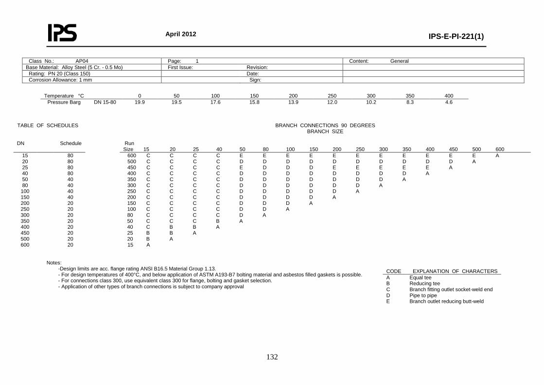
April 2012
IPS-E-PI-221(1)
132
Class No.: AP04 Page: 1 Content: General Base Material: Alloy Steel (5 Cr. - 0.5 Mo) First Issue: Revision: Rating: PN 20 (Class 150) Date: Corrosion Allowance: 1 mm Sign:
Temperature °C 0 50 100 150 200 250 300 350 400
Pressure Barg DN 15-80
19.9 19.5 17.6 15.8 13.9 12.0 10.2 8.3 4.6
Notes:
-Design limits are acc. flange rating ANSI B16.5 Material Group 1.13. - For design temperatures of 400°C, and below application of ASTM A193-B7 bolting material and asbestos filled gaskets is possible. - For connections class 300, use equivalent class 300 for flange, bolting and gasket selection. - Application of other types of branch connections is subject to company approval
TABLE OF SCHEDULES BRANCH CONNECTIONS 90 DEGREES BRANCH SIZE
DN Schedule Run
Size 15 20 25 40 50 80 100 150 200 250 300 350 400 450 500 600 15 20 25 40 50 80
100 150 200 250 300 350 400 450 500 600
80 80 80 80 40 40 40 40 20 20 20 20 20 20 20 20
600 C C C C E E E E E E E E E E E A 500 C C C C D D D D D D D D D D A 450 C C C C E D D D E E E E E A 400 C C C C D D D D D D D D A 350 C C C C D D D D D D D A 300 C C C C D D D D D D A 250 C C C C D D D D D A 200 C C C C D D D D A 150 C C C C D D D A 100 C C C C D D A 80 C C C C D A 50 C C C B A 40 C B B A 25 B B A 20 B A 15 A
CODE EXPLANATION OF CHARACTERS A Equal tee B Reducing tee C Branch fitting outlet socket-weld end D Pipe to pipe E Branch outlet reducing butt-weld
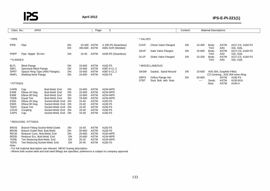
April 2012
IPS-E-PI-221(1)
133
Class No.: AP04 Page: 2 Content: Material Descriptions
* PIPE PIPE Pipe DN 15-400 ASTM A 335-P5 (Seamless) DN 450-600 ASTM A691-5CR (Welded) PNPP Pipe Nipple 50 mm DN 15-40 ASTM A335-P5 (Seamless) * FLANGES BLFL Blind Flange DN 15-600 ASTM A182-F5 SBFL Spectacle Blind Flange DN 15-600 ASTM A387-5 CL.2 SPRT Spacer Ring Type (ANS Flanges) DN 15-600 ASTM A387-5 CL.2 WNFL Welding Neck Flange DN 15-600 ASTM A182-F5 * FITTINGS CAPB Cap Butt-Weld. End DN 15-600 ASTM A234-WP5 E45B Elbow 45 Deg. Butt-Weld. End DN 15-600 ASTM A234-WP5 E90B Elbow 90 Deg. Butt-Weld. End DN 15-600 ASTM A234-WP5 TEEB Equal Tee Butt-Weld. End DN 15-600 ASTM A234-WP5 E45S Elbow 45 Deg. Socket-Weld. End DN 15-40 ASTM A182-F5 E90S Elbow 90 Deg. Socket-Weld. End DN 15-40 ASTM A182-F5 TEES Equal Tee Socket-Weld. End DN 15-40 ASTM A182-F5 COUS Coupling Socket-Weld. End DN 15-40 ASTM A182-F5 CAPS Cap Socket-Weld. End DN 15-40 ASTM A182-F5 * REDUCING FITTINGS BROS Branch Fitting Socket-Weld Outlet DN 15-40 ASTM A182-F5 BROB Branch Outlet Red. Butt-Weld. DN 50-600 ASTM A182-F5 RECB Reducer Conc. Butt-Weld. End DN 20-600 ASTM A234-WP5 REEB Reducer Ecc. Butt-Weld. End DN 20-600 ASTM A234-WP5 TERB Tee Reducing Butt-Weld. End DN 20-25 ASTM A234-WP5 TERS Tee Reducing Socket-Weld. End DN 20-40 ASTM A182-F5 Note: - For full material description see relevant MESC buying description. - Where both socket weld and butt weld fittings are specified, preference is subject to company approval.
* VALVES CHVF Check Valve Flanged DN 15-400 Body: ASTM A217-C5, A182-F5 Trim: AISI 316, 316L GAVF Gate Valve Flanged DN 15-600 Body: ASTM A217-C5, A182-F5 Trim: AISI 316, 316L GLVF Globe Valve Flanged DN 15-200 Body: ASTM A217-C5, A182-F5 Trim: AISI 316, 316L * MISCELLANEOUS GKSW Gasket, Spiral Wound DN 15-600 AISI 304, Graphite Filled, CS Centring-, AISI 304 Inner-Ring ORFS Orifice Flange Set DN 50-600 ASTM A182-F5 STBT Stud Bolt with Nuts ---- Studs: ASTM A193-B16 Nuts: ASTM A194-4
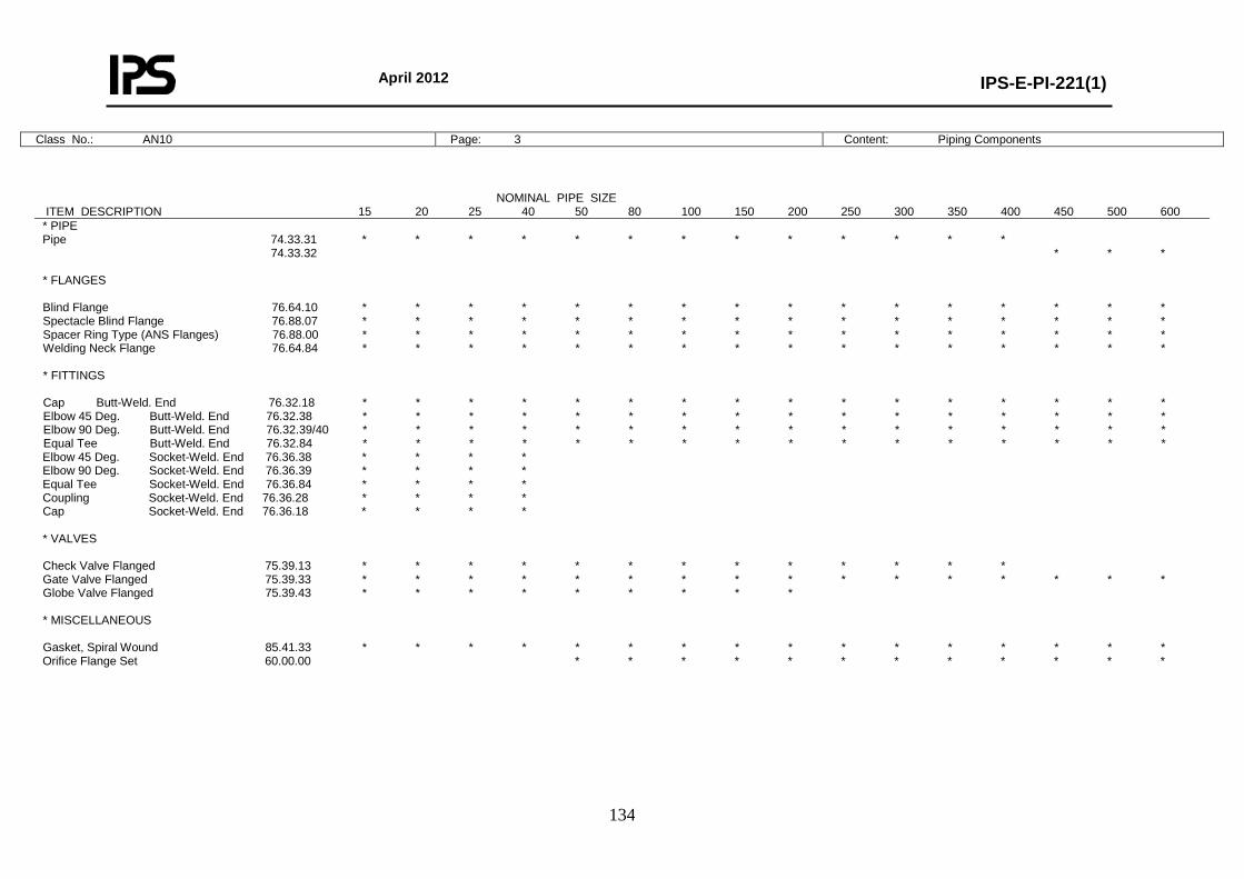
April 2012
IPS-E-PI-221(1)
134
Class No.: AN10 Page: 3 Content: Piping Components
NOMINAL PIPE SIZE ITEM DESCRIPTION 15 20 25 40 50 80 100 150 200 250 300 350 400 450 500 600 * PIPE Pipe 74.33.31 * * * * * * * * * * * * * 74.33.32 * * * * FLANGES Blind Flange 76.64.10 * * * * * * * * * * * * * * * * Spectacle Blind Flange 76.88.07 * * * * * * * * * * * * * * * * Spacer Ring Type (ANS Flanges) 76.88.00 * * * * * * * * * * * * * * * * Welding Neck Flange 76.64.84 * * * * * * * * * * * * * * * * * FITTINGS Cap Butt-Weld. End 76.32.18 * * * * * * * * * * * * * * * * Elbow 45 Deg. Butt-Weld. End 76.32.38 * * * * * * * * * * * * * * * * Elbow 90 Deg. Butt-Weld. End 76.32.39/40 * * * * * * * * * * * * * * * * Equal Tee Butt-Weld. End 76.32.84 * * * * * * * * * * * * * * * * Elbow 45 Deg. Socket-Weld. End 76.36.38 * * * * Elbow 90 Deg. Socket-Weld. End 76.36.39 * * * * Equal Tee Socket-Weld. End 76.36.84 * * * * Coupling Socket-Weld. End 76.36.28 * * * * Cap Socket-Weld. End 76.36.18 * * * * * VALVES Check Valve Flanged 75.39.13 * * * * * * * * * * * * * Gate Valve Flanged 75.39.33 * * * * * * * * * * * * * * * * Globe Valve Flanged 75.39.43 * * * * * * * * * * MISCELLANEOUS Gasket, Spiral Wound 85.41.33 * * * * * * * * * * * * * * * * Orifice Flange Set 60.00.00 * * * * * * * * * * * *
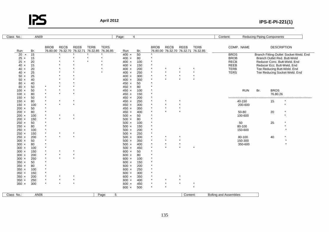
April 2012
IPS-E-PI-221(1)
135
Class No.: AN09 Page: 4 Content: Reducing Piping Components
Class No.: AN06 Page: 5 Content: Bolting and Assemblies
BROB RECB REEB TERB TERS Run Br. 76.80.00 76.32.70 76.32.71 76.32.85 76.36.85
BROB RECB REEB TERB Run Br. 76.80.00 76.32.70 76.32.71 76.32.85
COMP. NAME DESCRIPTION
20 × 15 * * * * 25 × 15 * * * * 25 × 20 * * * * 40 × 15 * * * 40 × 20 * * * 40 × 25 * * * 50 × 25 * * 50 × 40 * * 80 × 40 * * 80 × 50 * * * 100 × 50 * * * 100 × 80 * * * 150 × 50 * 150 × 80 * * * 150 × 100 * * * 200 × 50 * 200 × 80 * 200 × 100 * * * 200 × 150 * * * 250 × 50 * 250 × 80 * 250 × 100 * 250 × 150 * * * 250 × 200 * * * 300 × 50 * 300 × 80 * 300 × 100 * 300 × 150 * * * 300 × 200 * * * 300 × 250 * * * 350 × 50 * 350 × 80 * 350 × 100 * 350 × 150 * 350 × 200 * * * 350 × 250 * * * 350 × 300 * * *
400 × 50 * 400 × 80 * 400 × 100 * 400 × 150 * 400 × 200 * * * * 400 × 250 * * * * 400 × 300 * * * * 400 × 350 * * * * 450 × 50 * 450 × 80 * 450 × 100 * 450 × 150 * 450 × 200 * 450 × 250 * * * 450 × 300 * * * 450 × 350 * * * 450 × 400 * * * 500 × 50 * 500 × 80 * 500 × 100 * 500 × 150 * 500 × 200 * 500 × 250 * 500 × 300 * * * 500 × 350 * * * 500 × 400 * * * 500 × 450 * * * * 600 × 50 * 600 × 80 * 600 × 100 * 600 × 150 * 600 × 200 * 600 × 250 * 600 × 300 * 600 × 350 * * 600 × 400 * * * 600 × 450 * * * * 600 × 500 * * *
BROS Branch Fitting Outlet Socket-Weld. End BROB Branch Outlet Red. Butt-Weld RECB Reducer Conc. Butt-Weld. End REEB Reducer Ecc. Butt-Weld. End TERB Tee Reducing Butt-Weld. End TERS Tee Reducing Socket-Weld. End RUN Br. BROS 76.80.26 -------------------------------------------------------------------------------- 40-150 15 * 200-600 * 50-80 20 * 100-600 * 50 25 * 80-100 * 150-600 * 80-100 40 * 150-300 * 350-600 *

April 2012
IPS-E-PI-221(1)
136
DRAIN POINT Fig. 0I Run DN 15-25 Br DN 15 Run DN 40 Br DN 20 No. Branch: Table Page 1 1 Blind Flange 1 Gasket Spiral Wound 2 Gate Valve Flanged 1 Stud Bolt with Nuts 8 Welding Neck Flange 1 * DRAIN POINT Fig. 0J Run DN 50-600 Br DN 20 NO. Branch: Table Page 1 1 Blind Flange 1 Gasket Spiral Wound 2 Gate Valve Flanged 1 Pipe Nipple 50 mm 1 Stud Bolt with Nuts 8 Welding Neck Flange 1 * VENT POINT Fig. 1I Run DN 15-25 Br DN 15 Run DN 40 Br DN 20 NO. Branch: Table Page 1 1 Blind Flange 1 Gasket Spiral Wound 2 Globe Valve Flanged 1 Stud Bolt with Nuts 8 Welding Neck Flange 1 * VENT POINT Fig. 1J Run DN 50-600 Br DN 20 NO. Branch: Table Page 1 1 Blind Flange 1 Gasket Spiral Wound 2 Globe Valve Flanged 1 Pipe Nipple 50 mm 1 Stud Bolt with Nuts 8 Welding Neck Flange 1
BOLT SET FLANGED JOINTS DN No. Inch mm 81.38.96
BOLT SET ORIFICE FLANGES DN No. Inch mm 81.38.96
15 4 1/2 × 60 * 20 4 1/2 × 65 * 25 4 1/2 × 70 * 40 4 1/2 × 75 * 50 4 5/8 × 80 * 80 4 5/8 × 95 * 100 8 5/8 × 95 * 150 8 3/4 × 100 * 200 8 3/4 × 110 * 250 12 7/8 × 120 * 300 12 7/8 × 120 * 350 12 1 × 130 * 400 16 1 × 140 * 450 16 1-1/8 × 150 * 500 20 1-1/8 × 160 * 600 20 1-1/4 × 180 *
15 4 5/8 × 120 * 20 4 5/8 × 120 * 25 4 5/8 × 120 * 40 4 ¾ × 130 * 50 8 5/8 × 150 * 80 8 ¾ × 150 * 100 12 ¾ × 140 * 150 12 ¾ × 140 * 200 12 7/8 × 150 * 250 16 1 × 170 * 300 16 1-1/8 × 190 * 350 20 1-1/8 × 195 * 400 20 1-1/4 × 210 * 450 24 1-1/4 × 220 * 500 24 1-1/4 × 230 * 600 24 1-1/2 × 260 *
BOLT SET SPECTACLE/SPACER DN No. Inch mm 81.38.96 15 4 1/2 × 70 * 20 4 1/2 × 70 * 25 4 1/2 × 80 * 40 4 1/2 × 80 * 50 4 5/8 × 90 * 80 4 5/8 × 110 * 100 8 5/8 × 110 * 150 8 3/4 × 120 * 200 8 3/4 × 125 * 250 12 7/8 × 140 * 300 12 7/8 × 145 * 350 12 1 × 160 * 400 16 1 × 170 * 450 16 1-1/8 × 180 * 500 20 1-1/8 × 195 * 600 20 1-1/4 × 215 *
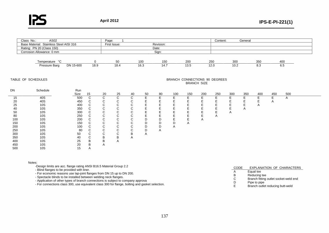
April 2012
IPS-E-PI-221(1)
137
Class No.: AS02 Page: 1 Content: General Base Material: Stainless Steel AISI 316 First Issue: Revision: Rating: PN 20 (Class 150) Date: Corrosion Allowance: 0 mm Sign:
Temperature °C 0 50 100 150 200 250 300 350 400
Pressure Barg DN 15-600
18.9 18.4 16.3 14.7 13.5 12.0 10.2 8.3 6.5
Notes:
-Design limits are acc. flange rating ANSI B16.5 Material Group 2.2 - Blind flanges to be provided with liner. - For economic reasons use lap-joint flanges from DN 15 up to DN 200. - Spectacle blinds to be installed between welding neck flanges. - Application of other types of branch connections is subject to company approva - For connections class 300, use equivalent class 300 for flange, bolting and gasket selection.
TABLE OF SCHEDULES BRANCH CONNECTIONS 90 DEGREES BRANCH SIZE
DN Schedule Run
Size 15 20 25 40 50 80 100 150 200 250 300 350 400 450 500 15 20 25 40 50 80
100 150 200 250 300 350 400 450 500
40S 40S 10S 10S 10S 10S 10S 10S 10S 10S 10S 10S 10S 10S 10S
500 C C C C E E E E E E E E E E A 450 C C C C E E E E E E E E E A 400 C C C C E E E E E E E E A 350 C C C C E E E E E E E A 300 C C C C E E E E E E A 250 C C C C E E E E E A 200 C C C C D D E E A 150 C C C C D D D A 100 C C C C D D A 80 C C C C D A 50 C C C B A 40 C B B A 25 B B A 20 B A 15 A
CODE EXPLANATION OF CHARACTERS A Equal tee B Reducing tee C Branch fitting outlet socket-weld end D Pipe to pipe E Branch outlet reducing butt-weld
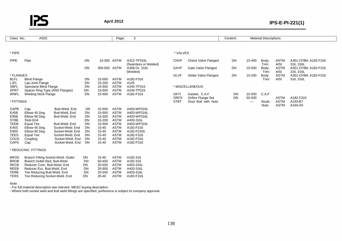
April 2012
IPS-E-PI-221(1)
138
Class No.: AS02 Page: 2 Content: Material Descriptions
* PIPE PIPE Pipe DN 15-300 ASTM A312-TP316L (Seamless or Welded) DN 350-500 ASTM A358-Gr. 316L (Welded) * FLANGES BLFL Blind Flange DN 15-500 ASTM A182-F316 LJFL Lap-Joint Flange DN 15-200 ASTM A105 SBFL Spectacle Blind Flange DN 15-500 ASTM A240-TP316 SPRT Spacer Ring Type (ANS Flanges) DN 15-500 ASTM A240-TP316 WNFL Welding Neck Flange DN 15-500 ASTM A182-F316 * FITTINGS CAPB Cap Butt-Weld. End DN 15-500 ASTM A403-WP316L E45B Elbow 45 Deg. Butt-Weld. End DN 15-500 ASTM A403-WP316L E90B Elbow 90 Deg. Butt-Weld. End DN 15-500 ASTM A403-WP316L STBE Stub-End DN 15-200 ASTM A403-316L TEEB Equal Tee Butt-Weld. End DN 15-500 ASTM A403-WP316L E45S Elbow 45 Deg. Socket-Weld. End DN 15-40 ASTM A182-F316 E90S Elbow 90 Deg. Socket-Weld. End DN 15-40 ASTM A182-F3165 TEES Equal Tee Socket-Weld. End DN 15-40 ASTM A182-F316 COUS Coupling Socket-Weld. End DN 15-40 ASTM A182-F316 CAPS Cap Socket-Weld. End DN 15-40 ASTM A182-F316 * REDUCING FITTINGS BROS Branch Fitting Socket-Weld. Outlet DN 15-40 ASTM A182-316 BROB Branch Outlet Red. Butt-Weld. DN 50-450 ASTM A182-316 RECB Reducer Conc. Butt-Weld. End DN 20-500 ASTM A403-316L REEB Reducer Ecc. Butt-Weld. End DN 20-500 ASTM A403-316L TERB Tee Reducing Butt-Weld. End DN 20-500 ASTM A403-316L TERS Tee Reducing Socket-Weld. End DN 20-40 ASTM A182-F316 Note: - For full material description see relevant MESC buying description. - Where both socket weld and butt weld fittings are specified, preference is subject to company approval.
* VALVES CHVF Check Valve Flanged DN 15-400 Body: ASTM A351-CF8M, A182-F316 Trim: AISI 316, 316L GAVF Gate Valve Flanged DN 15-500 Body: ASTM A351-CF8M, A182-F316 Trim: AISI 316, 316L GLVF Globe Valve Flanged DN 15-200 Body: ASTM A351-CF8M, A182-F316 Trim: AISI 316, 316L * MISCELLANEOUS GKTI Gasket, C.A.F DN 15-500 C.A.F ORFS Orifice Flange Set DN 50-500 ASTM A182-F316 STBT Stud Bolt with Nuts ---- Studs: ASTM A193-B7 Nuts: ASTM A194-2H
April 2012
IPS-E-PI-221(1)
139
Class No.: AS02 Page: 3 Content: Piping Components
NOMINAL PIPE SIZE ITEM DESCRIPTION 15 20 25 40 50 80 100 150 200 250 300 350 400 450 500 * PIPE Pipe 74.36.40 * * * * * * * * * * * 74.36.00 * * * * * FLANGES Blind Flange 76.65.10 * * * * * * * * * * * * * * * Lap-Joint Flanged 76.62.20 * * * * * * * * * Spectacle Blind Flange 76.88.10 * * * * * * * * * * * * * * * Spacer Ring Type (ANS Flanges) 76.88.00 * * * * * * * * * * * * * * * Welding Neck Flange 76.65.80 * * * * * * * * * * * * * * * * FITTINGS Cap Butt-Weld. End 76.33.18 * * * * * * * * * * * * * * * Elbow 45 Deg. Butt-Weld. End 76.33.38 * * * * * * * * * * * * * * * Elbow 90 Deg. Butt-Weld. End 76.33.40 * * * * * * * * * * * * * * * Stub-End 76.33.53 * * * * * * * * * Equal Tee Butt-Weld. End 76.33.84 * * * * * * * * * * * * * * * Elbow 45 Deg. Socket-Weld. End 76.37.38 * * * * Elbow 90 Deg. Socket-Weld. End 76.37.39 * * * * Equal Tee Socket-Weld. End 76.37.84 * * * * Coupling Socket-Weld. End 76.37.28 * * * * Cap Socket-Weld. End 76.37.18 * * * * * VALVES Check Valve Flanged 75.40.13 * * * * * * * * * * * * * Gate Valve Flanged 75.40.33 * * * * * * * * * * * * * * * Globe Valve Flanged 75.40.40 * * * * * * * * * * MISCELLANEOUS Gasket, RF C.A.F. 85.31.16/17 * * * * * * * * * * * * * * * Orifice Flange Set 60.00.00 * * * * * * * * * * *
April 2012
IPS-E-PI-221(1)
140
Class No.: AS02 Page: 4 Content: Reducing Piping Components
BROB RECB REEB TERB TERS Run Br. 76.00.00 76.33.70 76.33.73 76.33.85 76.37.85
BROB RECB REEB TERB Run Br. 76.00.00 76.33.70 76.33.73 76.33.85
COMP. NAME DESCRIPTION
20 × 15 * * * * 25 × 15 * * * * 25 × 20 * * * * 40 × 15 * * 40 × 20 * * * * 40 × 25 * * * * 50 × 20 * 50 × 25 * * * 50 × 40 * * * 80 × 40 * * * 80 × 50 * * * * 100 × 40 * 100 × 50 * * * * 100 × 80 * * * * 150 × 50 * 150 × 80 * * * * 150 × 100 * * * * 200 × 50 * 200 × 80 * 200 × 100 * * * * 200 × 150 * * * * 250 × 50 * 250 × 80 * 250 × 100 * * 250 × 150 * * * * 250 × 200 * * * * 300 × 50 * 300 × 80 * 300 × 100 * 300 × 150 * * * * 300 × 200 * * * * 300 × 250 * * * * 350 × 50 * 350 × 80 * 350 × 100 * 350 × 150 * * 350 × 200 * * * * 350 × 250 * * * * 350 × 300 * * * *
400 × 50 * 400 × 80 * 400 × 100 * 400 × 150 * * 400 × 200 * * * * 400 × 250 * * * * 400 × 300 * * * * 400 × 350 * * * * 450 × 50 * 450 × 80 * 450 × 100 * 450 × 150 * 450 × 200 * 450 × 250 * * * 450 × 300 * * * 450 × 350 * * * 450 × 400 * * * 500 × 50 500 × 80 500 × 100 500 × 150 500 × 200 * 500 × 250 * 500 × 300 * * * 500 × 350 * * 500 × 400 * * * 500 × 450 * * *
BROS Branch
Fitting Outlet Socket-Weld. End
BROB Branch Outlet Red. Butt-Weld RECB Reducer Conc. Butt-Weld. End REEB Reducer Ecc. Butt-Weld. End TERB Tee Reducing Butt-Weld. End TERS Tee Reducing Socket-Weld. End RUN Br. BROS 76.80.26 ------------------------------------------------------------------------- 40-150 15 * 200-500 * 50-80 20 * 100-500 * 50 25 * 80-100 * 150-500 * 80-100 40 * 150-300 * 350-500 *
April 2012
IPS-E-PI-221(1)
141
Class No.: AS02 Page: 5 Content: Bolting and Assemblies
DRAIN POINT Fig. 0V Run DN 15-25 Br DN 15 Run DN 40 Br DN 20 No. Branch: Table Page 1 1 Blind Flange 1 Blind Flange Liner 1 Gasket RF. C.A.F. 2 Gate Valve Flanged 1 Lap-Joint Flange 1 Stub-End 1 Stud Bolt with Nuts 4 * DRAIN POINT Fig. 0R Run DN 50-500 Br DN 20 No. Branch: BROB 1 Blind Flange 1 Blind Flange Liner 1 Gasket RF. C.A.F. 2 Gate Valve Flanged 1 Stud Bolt with Nuts 8 Welding Neck Flange 1 * VENT POINT Fig. 1V Run DN 15-25 Br DN 15 Run DN 40 Br DN 20 No. Branch: Table Page 1 1 Blind Flange 1 Blind Flange Liner 1 Gasket RF. C.A.F. 2 Globe Valve Flanged 1 Lap-Joint Flange 1 Stub-End 1 Stud Bolt with Nuts 4 * VENT POINT Fig. 1R Run DN 50-500 Br DN 20 No. Branch: BROB 1 Blind Flange 1 Blind Flange Liner 1 Gasket RF. C.A.F. 2 Globe Valve Flanged 1 Stud Bolt with Nuts 8 Welding Neck Flange 1
Class No.: AS04 Page: 1 Content: General
BOLT SET FLANGED JOINTS DN No. Inch mm 81.38.61
BOLT SET ORIFICE FLANGES DN No. Inch mm 81.38.61
15 4 1/2 × 60 * 20 4 1/2 × 65 * 25 4 1/2 × 70 * 40 4 1/2 × 75 * 50 4 5/8 × 80 * 80 4 5/8 × 95 * 100 8 5/8 × 95 * 150 8 3/4 × 100 * 200 8 3/4 × 110 * 250 12 7/8 × 120 * 300 12 7/8 × 120 * 350 12 1 × 130 * 400 16 1 × 140 * 450 16 1-1/8 × 150 * 500 20 1-1/8 × 160 *
15 4 5/8 × 120 * 20 4 5/8 × 120 * 25 4 5/8 × 120 * 40 4 ¾ × 130 * 50 8 5/8 × 150 * 80 8 ¾ × 150 * 100 12 ¾ × 140 * 150 12 ¾ × 140 * 200 12 7/8 × 150 * 250 16 1 × 170 * 300 16 1-1/8 × 190 * 350 20 1-1/8 × 195 * 400 20 1-1/4 × 210 * 450 24 1-1/4 × 220 * 500 24 1-1/4 × 230 *
BOLT SET SPECTACLE/SPACER DN No. Inch mm 81.38.61 15 4 1/2 × 70 * 20 4 1/2 × 70 * 25 4 1/2 × 80 * 40 4 1/2 × 80 * 50 4 5/8 × 90 * 80 4 5/8 × 110 * 100 8 5/8 × 110 * 150 8 3/4 × 120 * 200 8 3/4 × 125 * 250 12 7/8 × 140 * 300 12 7/8 × 145 * 350 12 1 × 160 * 400 16 1 × 170 * 450 16 1-1/8 × 180 * 500 20 1-1/8 × 195 *
April 2012
IPS-E-PI-221(1)
142
Base Material: Stainless Steel AISI 304, LT First Issue: Revision: Rating: PN 20 (Class 150) Date: Corrosion Allowance: 0 mm Sign:
Temperature °C -200 0 50 100 150
Pressure Barg DN 15-600
18.9 18.9 18.3 15.9 14.1
Notes:
-Design limits are acc. flange rating ANSI B16.5 Material Group 2.1. - Application of other types of branch connections is subject to company approval - For connections class 300, use equivalent class 300 for flange, bolting and gasket selection
Class No.: AS04 Page: 2 Content: Material Descriptions
TABLE OF SCHEDULES BRANCH CONNECTIONS 90 DEGREES BRANCH SIZE
DN Schedule Run
Size 15 20 25 40 50 80 100 150 200 250 300 350 400 450 500 600 15 20 25 40 50 80
100 150 200 250 300 350 400 450 500 600
40S 40S 10S 10S 10S 10S 10S 10S 10S 10S 10S 10S 10S 10S 10S 10S
600 C C C C E E E E E E E E E E E A 500 C C C C E E E E E E E E E E A 450 C C C C E E E E E E E E E A 400 C C C C E E E E E E E E A 350 C C C C E E E E E E E A 300 C C C C D E E E E E A 250 C C C C D D D D D A 200 C C C C D D D D A 150 C C C C D D D A 100 C C C C D D A 80 C C C C D A 50 C C C B A 40 C B B A 25 B B A 20 B A 15 A
CODE EXPLANATION OF CHARACTERS A Equal tee B Reducing tee C Branch fitting outlet socket-weld end D Pipe to pipe E Branch outlet reducing butt-weld
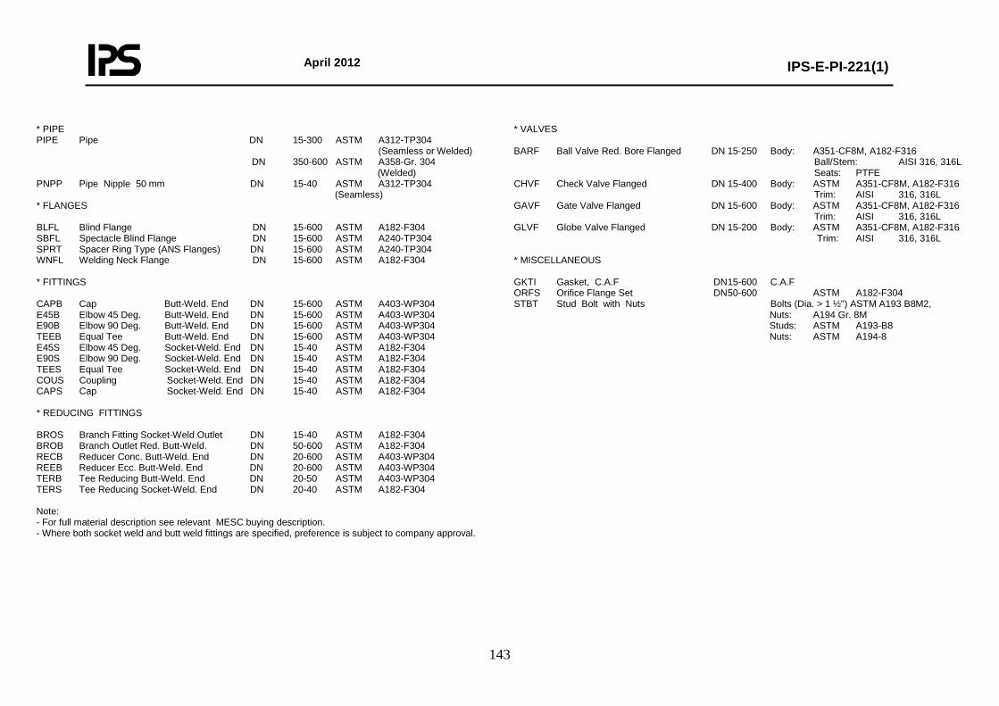
April 2012
IPS-E-PI-221(1)
143
* PIPE PIPE Pipe DN 15-300 ASTM A312-TP304 (Seamless or Welded) DN 350-600 ASTM A358-Gr. 304 (Welded) PNPP Pipe Nipple 50 mm DN 15-40 ASTM A312-TP304 (Seamless) * FLANGES BLFL Blind Flange DN 15-600 ASTM A182-F304 SBFL Spectacle Blind Flange DN 15-600 ASTM A240-TP304 SPRT Spacer Ring Type (ANS Flanges) DN 15-600 ASTM A240-TP304 WNFL Welding Neck Flange DN 15-600 ASTM A182-F304 * FITTINGS CAPB Cap Butt-Weld. End DN 15-600 ASTM A403-WP304 E45B Elbow 45 Deg. Butt-Weld. End DN 15-600 ASTM A403-WP304 E90B Elbow 90 Deg. Butt-Weld. End DN 15-600 ASTM A403-WP304 TEEB Equal Tee Butt-Weld. End DN 15-600 ASTM A403-WP304 E45S Elbow 45 Deg. Socket-Weld. End DN 15-40 ASTM A182-F304 E90S Elbow 90 Deg. Socket-Weld. End DN 15-40 ASTM A182-F304 TEES Equal Tee Socket-Weld. End DN 15-40 ASTM A182-F304 COUS Coupling Socket-Weld. End DN 15-40 ASTM A182-F304 CAPS Cap Socket-Weld. End DN 15-40 ASTM A182-F304 * REDUCING FITTINGS BROS Branch Fitting Socket-Weld Outlet DN 15-40 ASTM A182-F304 BROB Branch Outlet Red. Butt-Weld. DN 50-600 ASTM A182-F304 RECB Reducer Conc. Butt-Weld. End DN 20-600 ASTM A403-WP304 REEB Reducer Ecc. Butt-Weld. End DN 20-600 ASTM A403-WP304 TERB Tee Reducing Butt-Weld. End DN 20-50 ASTM A403-WP304 TERS Tee Reducing Socket-Weld. End DN 20-40 ASTM A182-F304 Note: - For full material description see relevant MESC buying description. - Where both socket weld and butt weld fittings are specified, preference is subject to company approval.
* VALVES BARF Ball Valve Red. Bore Flanged DN 15-250 Body: A351-CF8M, A182-F316 Ball/Stem: AISI 316, 316L Seats: PTFE CHVF Check Valve Flanged DN 15-400 Body: ASTM A351-CF8M, A182-F316 Trim: AISI 316, 316L GAVF Gate Valve Flanged DN 15-600 Body: ASTM A351-CF8M, A182-F316 Trim: AISI 316, 316L GLVF Globe Valve Flanged DN 15-200 Body: ASTM A351-CF8M, A182-F316 Trim: AISI 316, 316L * MISCELLANEOUS GKTI Gasket, C.A.F DN 15-600 C.A.F ORFS Orifice Flange Set DN 50-600 ASTM A182-F304 STBT Stud Bolt with Nuts Bolts (Dia. > 1 ½") ASTM A193 B8M2, Nuts: A194 Gr. 8M Studs: ASTM A193-B8 Nuts: ASTM A194-8
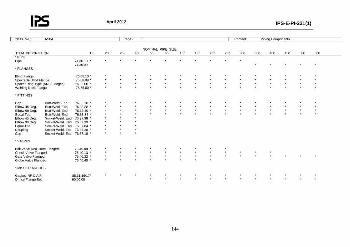
April 2012
IPS-E-PI-221(1)
144
Class No.: AS04 Page: 3 Content: Piping Components
NOMINAL PIPE SIZE ITEM DESCRIPTION 15 20 25 40 50 80 100 150 200 250 300 350 400 450 500 600 * PIPE Pipe 74.36.10 * * * * * * * * * * * 74.36.00 * * * * * * FLANGES Blind Flange 76.65.10 * * * * * * * * * * * * * * * * Spectacle Blind Flange 76.88.09 * * * * * * * * * * * * * * * * Spacer Ring Type (ANS Flanges) 76.88.00 * * * * * * * * * * * * * * * * Welding Neck Flange 76.65.80 * * * * * * * * * * * * * * * * * FITTINGS Cap Butt-Weld. End 76.33.18 * * * * * * * * * * * * * * * * Elbow 45 Deg. Butt-Weld. End 76.33.38 * * * * * * * * * * * * * * * * Elbow 90 Deg. Butt-Weld. End 76.33.40 * * * * * * * * * * * * * * * * Equal Tee Butt-Weld. End 76.33.84 * * * * * * * * * * * * * * * * Elbow 45 Deg. Socket-Weld. End 76.37.38 * * * * Elbow 90 Deg. Socket-Weld. End 76.37.39 * * * * Equal Tee Socket-Weld. End 76.37.84 * * * * Coupling Socket-Weld. End 76.37.28 * * * * Cap Socket-Weld. End 76.37.18 * * * * * VALVES Ball Valve Red. Bore Flanged 75.40.08 * * * * * * * * * * Check Valve Flanged 75.40.13 * * * * * * * * * * * * * Gate Valve Flanged 75.40.33 * * * * * * * * * * * * * * * * Globe Valve Flanged 75.40.40 * * * * * * * * * * MISCELLANEOUS Gasket, RF C.A.F. 85.31.16/17 * * * * * * * * * * * * * * * * Orifice Flange Set 60.00.00 * * * * * * * * * * * *
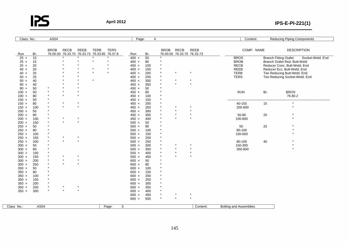
April 2012
IPS-E-PI-221(1)
145
Class No.: AS04 Page: 4 Content: Reducing Piping Components
Class No.: AS04 Page: 5 Content: Bolting and Assemblies
BROB RECB REEB TERB TERS Run Br. 76.00.00 76.33.70 76.33.73 76.33.85 76.37.8
BROB RECB REEB Run Br. 76.00.00 76.33.70 76.33.73
COMP. NAME DESCRIPTION
20 × 15 * * * * 25 × 15 * * * * 25 × 20 * * * 40 × 20 * * * * 40 × 25 * * * * 50 × 25 * * 50 × 40 * * * 80 × 40 * * 80 × 50 * * * 100 × 50 * * * 100 × 80 * * * 150 × 50 * 150 × 80 * * * 150 × 100 * * * 200 × 50 * 200 × 80 * 200 × 100 * * * 200 × 150 * * * 250 × 50 * 250 × 80 * 250 × 100 * 250 × 150 * * * 250 × 200 * * * 300 × 50 * 300 × 80 * 300 × 100 * 300 × 150 * * * 300 × 200 * * * 300 × 250 * * * 350 × 50 * 350 × 80 * 350 × 100 * 350 × 150 * 350 × 200 * 350 × 250 * * * 350 × 300 * * *
400 × 50 * 400 × 80 * 400 × 100 * 400 × 150 * 400 × 200 * * * 400 × 250 * 400 × 300 * * * 400 × 350 * * * 450 × 50 * 450 × 80 * 450 × 100 * 450 × 150 * 450 × 200 * 450 × 250 * * * 450 × 300 * * * 450 × 350 * * * 450 × 400 * * * 500 × 50 * 500 × 80 * 500 × 100 * 500 × 150 * 500 × 200 * 500 × 250 * 500 × 300 * * * 500 × 350 * * * 500 × 400 * * * 500 × 450 * * * 600 × 50 * 600 × 80 * 600 × 100 * 600 × 150 * 600 × 200 * 600 × 250 * 600 × 300 * 600 × 350 * 600 × 400 * 600 × 450 * * * 600 × 500 * * *
BROS Branch Fitting Outlet Socket-Weld. End BROB Branch Outlet Red. Butt-Weld RECB Reducer Conc. Butt-Weld. End REEB Reducer Ecc. Butt-Weld. End TERB Tee Reducing Butt-Weld. End TERS Tee Reducing Socket-Weld. End RUN Br. BROS 76.80.2 --------------------------------------------------------------------------------------------- 40-150 15 * 200-600 * 50-80 20 * 100-600 * 50 25 * 80-100 * 150-600 * 80-100 40 * 150-300 * 350-600 *
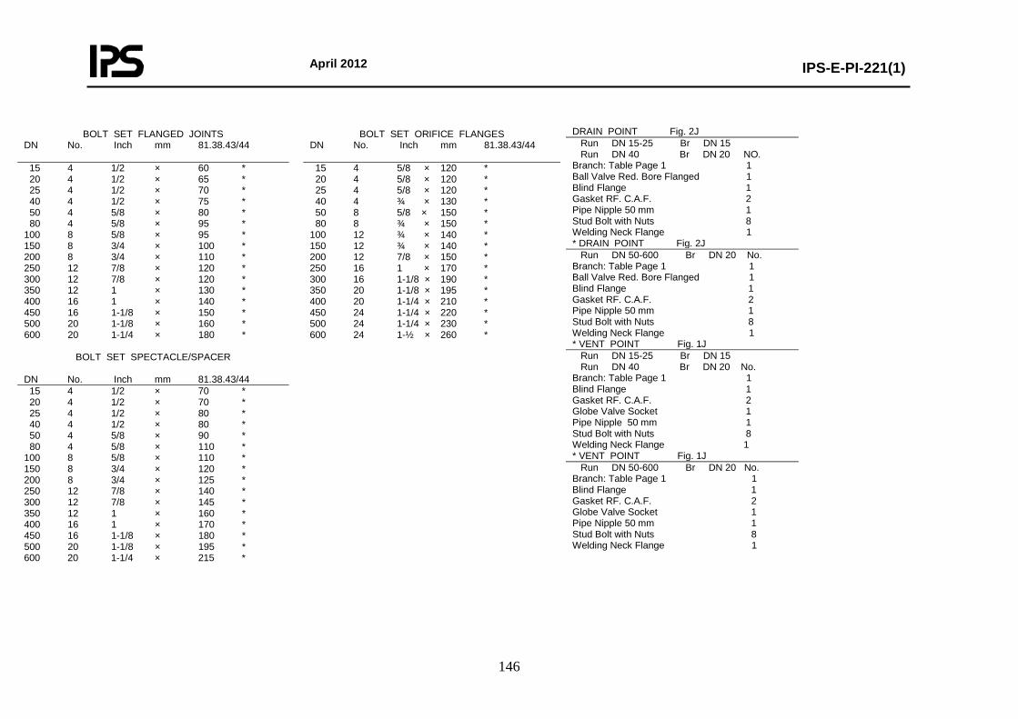
April 2012
IPS-E-PI-221(1)
146
DRAIN POINT Fig. 2J Run DN 15-25 Br DN 15 Run DN 40 Br DN 20 NO. Branch: Table Page 1 1 Ball Valve Red. Bore Flanged 1 Blind Flange 1 Gasket RF. C.A.F. 2 Pipe Nipple 50 mm 1 Stud Bolt with Nuts 8 Welding Neck Flange 1 * DRAIN POINT Fig. 2J Run DN 50-600 Br DN 20 No. Branch: Table Page 1 1 Ball Valve Red. Bore Flanged 1 Blind Flange 1 Gasket RF. C.A.F. 2 Pipe Nipple 50 mm 1 Stud Bolt with Nuts 8 Welding Neck Flange 1 * VENT POINT Fig. 1J Run DN 15-25 Br DN 15 Run DN 40 Br DN 20 No. Branch: Table Page 1 1 Blind Flange 1 Gasket RF. C.A.F. 2 Globe Valve Socket 1 Pipe Nipple 50 mm 1 Stud Bolt with Nuts 8 Welding Neck Flange 1 * VENT POINT Fig. 1J Run DN 50-600 Br DN 20 No. Branch: Table Page 1 1 Blind Flange 1 Gasket RF. C.A.F. 2 Globe Valve Socket 1 Pipe Nipple 50 mm 1 Stud Bolt with Nuts 8 Welding Neck Flange 1
BOLT SET FLANGED JOINTS DN No. Inch mm 81.38.43/44
BOLT SET ORIFICE FLANGES DN No. Inch mm 81.38.43/44
15 4 1/2 × 60 * 20 4 1/2 × 65 * 25 4 1/2 × 70 * 40 4 1/2 × 75 * 50 4 5/8 × 80 * 80 4 5/8 × 95 * 100 8 5/8 × 95 * 150 8 3/4 × 100 * 200 8 3/4 × 110 * 250 12 7/8 × 120 * 300 12 7/8 × 120 * 350 12 1 × 130 * 400 16 1 × 140 * 450 16 1-1/8 × 150 * 500 20 1-1/8 × 160 * 600 20 1-1/4 × 180 *
15 4 5/8 × 120 * 20 4 5/8 × 120 * 25 4 5/8 × 120 * 40 4 ¾ × 130 * 50 8 5/8 × 150 * 80 8 ¾ × 150 * 100 12 ¾ × 140 * 150 12 ¾ × 140 * 200 12 7/8 × 150 * 250 16 1 × 170 * 300 16 1-1/8 × 190 * 350 20 1-1/8 × 195 * 400 20 1-1/4 × 210 * 450 24 1-1/4 × 220 * 500 24 1-1/4 × 230 * 600 24 1-½ × 260 *
BOLT SET SPECTACLE/SPACER DN No. Inch mm 81.38.43/44 15 4 1/2 × 70 * 20 4 1/2 × 70 * 25 4 1/2 × 80 * 40 4 1/2 × 80 * 50 4 5/8 × 90 * 80 4 5/8 × 110 * 100 8 5/8 × 110 * 150 8 3/4 × 120 * 200 8 3/4 × 125 * 250 12 7/8 × 140 * 300 12 7/8 × 145 * 350 12 1 × 160 * 400 16 1 × 170 * 450 16 1-1/8 × 180 * 500 20 1-1/8 × 195 * 600 20 1-1/4 × 215 *
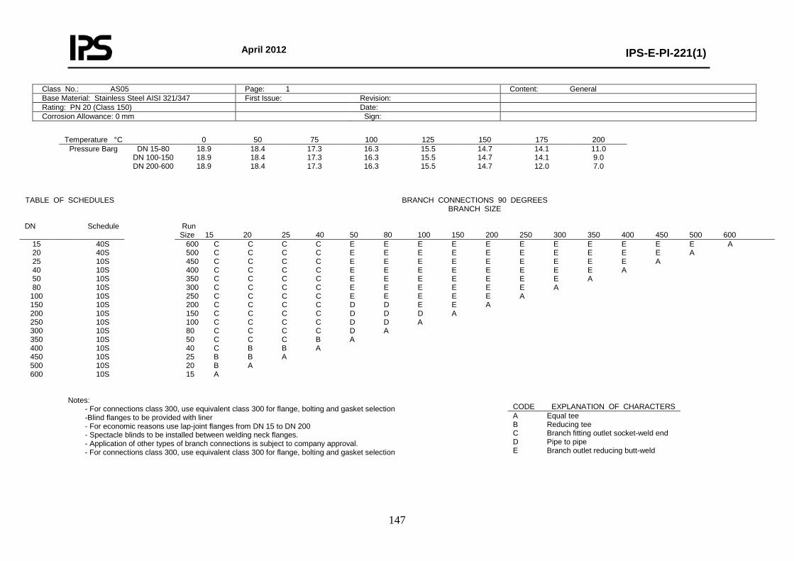
April 2012
IPS-E-PI-221(1)
147
Class No.: AS05 Page: 1 Content: General Base Material: Stainless Steel AISI 321/347 First Issue: Revision: Rating: PN 20 (Class 150) Date: Corrosion Allowance: 0 mm Sign:
Temperature °C 0 50 75 100 125 150 175 200
Pressure Barg DN 15-80 DN 100-150 DN 200-600
18.9 18.9 18.9
18.4 18.4 18.4
17.3 17.3 17.3
16.3 16.3 16.3
15.5 15.5 15.5
14.7 14.7 14.7
14.1 14.1 12.0
11.0 9.0 7.0
Notes:
- For connections class 300, use equivalent class 300 for flange, bolting and gasket selection -Blind flanges to be provided with liner - For economic reasons use lap-joint flanges from DN 15 to DN 200 - Spectacle blinds to be installed between welding neck flanges. - Application of other types of branch connections is subject to company approval.
- For connections class 300, use equivalent class 300 for flange, bolting and gasket selection
TABLE OF SCHEDULES BRANCH CONNECTIONS 90 DEGREES BRANCH SIZE
DN Schedule Run
Size 15 20 25 40 50 80 100 150 200 250 300 350 400 450 500 600 15 20 25 40 50 80
100 150 200 250 300 350 400 450 500 600
40S 40S 10S 10S 10S 10S 10S 10S 10S 10S 10S 10S 10S 10S 10S 10S
600 C C C C E E E E E E E E E E E A 500 C C C C E E E E E E E E E E A 450 C C C C E E E E E E E E E A 400 C C C C E E E E E E E E A 350 C C C C E E E E E E E A 300 C C C C E E E E E E A 250 C C C C E E E E E A 200 C C C C D D E E A 150 C C C C D D D A 100 C C C C D D A 80 C C C C D A 50 C C C B A 40 C B B A 25 B B A 20 B A 15 A
CODE EXPLANATION OF CHARACTERS A Equal tee B Reducing tee C Branch fitting outlet socket-weld end D Pipe to pipe E Branch outlet reducing butt-weld
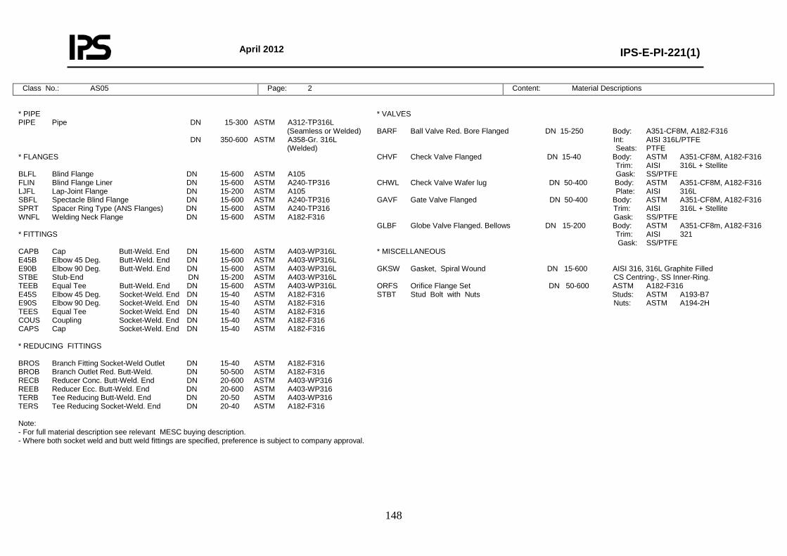
April 2012
IPS-E-PI-221(1)
148
Class No.: AS05 Page: 2 Content: Material Descriptions
* PIPE PIPE Pipe DN 15-300 ASTM A312-TP316L (Seamless or Welded) DN 350-600 ASTM A358-Gr. 316L (Welded) * FLANGES BLFL Blind Flange DN 15-600 ASTM A105 FLIN Blind Flange Liner DN 15-600 ASTM A240-TP316 LJFL Lap-Joint Flange DN 15-200 ASTM A105 SBFL Spectacle Blind Flange DN 15-600 ASTM A240-TP316 SPRT Spacer Ring Type (ANS Flanges) DN 15-600 ASTM A240-TP316 WNFL Welding Neck Flange DN 15-600 ASTM A182-F316 * FITTINGS CAPB Cap Butt-Weld. End DN 15-600 ASTM A403-WP316L E45B Elbow 45 Deg. Butt-Weld. End DN 15-600 ASTM A403-WP316L E90B Elbow 90 Deg. Butt-Weld. End DN 15-600 ASTM A403-WP316L STBE Stub-End DN 15-200 ASTM A403-WP316L TEEB Equal Tee Butt-Weld. End DN 15-600 ASTM A403-WP316L E45S Elbow 45 Deg. Socket-Weld. End DN 15-40 ASTM A182-F316 E90S Elbow 90 Deg. Socket-Weld. End DN 15-40 ASTM A182-F316 TEES Equal Tee Socket-Weld. End DN 15-40 ASTM A182-F316 COUS Coupling Socket-Weld. End DN 15-40 ASTM A182-F316 CAPS Cap Socket-Weld. End DN 15-40 ASTM A182-F316 * REDUCING FITTINGS BROS Branch Fitting Socket-Weld Outlet DN 15-40 ASTM A182-F316 BROB Branch Outlet Red. Butt-Weld. DN 50-500 ASTM A182-F316 RECB Reducer Conc. Butt-Weld. End DN 20-600 ASTM A403-WP316 REEB Reducer Ecc. Butt-Weld. End DN 20-600 ASTM A403-WP316 TERB Tee Reducing Butt-Weld. End DN 20-50 ASTM A403-WP316 TERS Tee Reducing Socket-Weld. End DN 20-40 ASTM A182-F316 Note: - For full material description see relevant MESC buying description. - Where both socket weld and butt weld fittings are specified, preference is subject to company approval.
* VALVES BARF Ball Valve Red. Bore Flanged DN 15-250 Body: A351-CF8M, A182-F316 Int: AISI 316L/PTFE Seats: PTFE CHVF Check Valve Flanged DN 15-40 Body: ASTM A351-CF8M, A182-F316 Trim: AISI 316L + Stellite Gask: SS/PTFE CHWL Check Valve Wafer lug DN 50-400 Body: ASTM A351-CF8M, A182-F316 Plate: AISI 316L GAVF Gate Valve Flanged DN 50-400 Body: ASTM A351-CF8M, A182-F316 Trim: AISI 316L + Stellite Gask: SS/PTFE GLBF Globe Valve Flanged. Bellows DN 15-200 Body: ASTM A351-CF8m, A182-F316 Trim: AISI 321 Gask: SS/PTFE * MISCELLANEOUS GKSW Gasket, Spiral Wound DN 15-600 AISI 316, 316L Graphite Filled CS Centring-, SS Inner-Ring. ORFS Orifice Flange Set DN 50-600 ASTM A182-F316 STBT Stud Bolt with Nuts Studs: ASTM A193-B7 Nuts: ASTM A194-2H
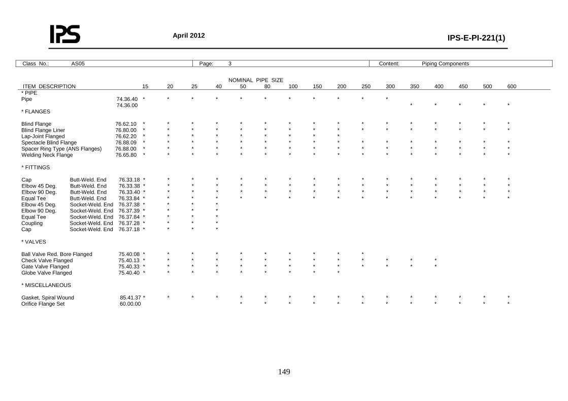
April 2012
IPS-E-PI-221(1)
149
Class No.: AS05 Page: 3 Content: Piping Components
NOMINAL PIPE SIZE ITEM DESCRIPTION 15 20 25 40 50 80 100 150 200 250 300 350 400 450 500 600 * PIPE Pipe 74.36.40 * * * * * * * * * * * 74.36.00 * * * * * * FLANGES Blind Flange 76.62.10 * * * * * * * * * * * * * * * * Blind Flange Liner 76.80.00 * * * * * * * * * * * * * * * * Lap-Joint Flanged 76.62.20 * * * * * * * * * Spectacle Blind Flange 76.88.09 * * * * * * * * * * * * * * * * Spacer Ring Type (ANS Flanges) 76.88.00 * * * * * * * * * * * * * * * * Welding Neck Flange 76.65.80 * * * * * * * * * * * * * * * * * FITTINGS Cap Butt-Weld. End 76.33.18 * * * * * * * * * * * * * * * * Elbow 45 Deg. Butt-Weld. End 76.33.38 * * * * * * * * * * * * * * * * Elbow 90 Deg. Butt-Weld. End 76.33.40 * * * * * * * * * * * * * * * * Equal Tee Butt-Weld. End 76.33.84 * * * * * * * * * * * * * * * * Elbow 45 Deg. Socket-Weld. End 76.37.38 * * * * Elbow 90 Deg. Socket-Weld. End 76.37.39 * * * * Equal Tee Socket-Weld. End 76.37.84 * * * * Coupling Socket-Weld. End 76.37.28 * * * * Cap Socket-Weld. End 76.37.18 * * * * * VALVES Ball Valve Red. Bore Flanged 75.40.08 * * * * * * * * * * Check Valve Flanged 75.40.13 * * * * * * * * * * * * * Gate Valve Flanged 75.40.33 * * * * * * * * * * * * * Globe Valve Flanged 75.40.40 * * * * * * * * * * MISCELLANEOUS Gasket, Spiral Wound 85.41.37 * * * * * * * * * * * * * * * * Orifice Flange Set 60.00.00 * * * * * * * * * * * *
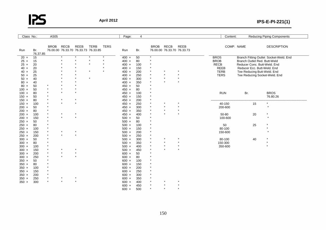
April 2012
IPS-E-PI-221(1)
150
Class No.: AS05 Page: 4 Content: Reducing Piping Components
BROB RECB REEB TERB TERS Run Br. 76.00.00 76.33.70 76.33.73 76.33.85 76.37.85
BROB RECB REEB Run Br. 76.00.00 76.33.70 76.33.73
COMP. NAME DESCRIPTION
20 × 15 * * * * 25 × 15 * * * * 25 × 20 * * * * 40 × 20 * * * 40 × 25 * * * * 50 × 25 * * 50 × 40 * * * 80 × 40 * * 80 × 50 * * * 100 × 50 * * * 100 × 80 * * * 150 × 50 * 150 × 80 * * * 150 × 100 * * * 200 × 50 * 200 × 80 * 200 × 100 * * * 200 × 150 * * * 250 × 50 * 250 × 80 * 250 × 100 * 250 × 150 * * * 250 × 200 * * * 300 × 50 * 300 × 80 * 300 × 100 * 300 × 150 * * * 300 × 200 * * * 300 × 250 * * * 350 × 50 * 350 × 80 * 350 × 100 * 350 × 150 * 350 × 200 * 350 × 250 * * * 350 × 300 * * *
400 × 50 * 400 × 80 * 400 × 100 * 400 × 150 * 400 × 200 * * * 400 × 250 * * * 400 × 300 * * * 400 × 350 * * * 450 × 50 * 450 × 80 * 450 × 100 * 450 × 150 * 450 × 200 * 450 × 250 * * * 450 × 300 * * * 450 × 350 * * * 450 × 400 * * * 500 × 50 * 500 × 80 * 500 × 100 * 500 × 150 * 500 × 200 * 500 × 250 * 500 × 300 * * * 500 × 350 * * * 500 × 400 * * * 500 × 450 * * * 600 × 50 * 600 × 80 * 600 × 100 * 600 × 150 * 600 × 200 * 600 × 250 * 600 × 300 * 600 × 350 * 600 × 400 * * * 600 × 450 * * * 600 × 500 * * *
BROS Branch Fitting Outlet Socket-Weld. End BROB Branch Outlet Red. Butt-Weld RECB Reducer Conc. Butt-Weld. End REEB Reducer Ecc. Butt-Weld. End TERB Tee Reducing Butt-Weld. End TERS Tee Reducing Socket-Weld. End RUN Br. BROS 76.80.26 --------------------------------------------------------------------------------------------- 40-150 15 * 200-600 * 50-80 20 * 100-600 * 50 25 * 80-100 * 150-600 * 80-100 40 * 150-300 * 350-600 *
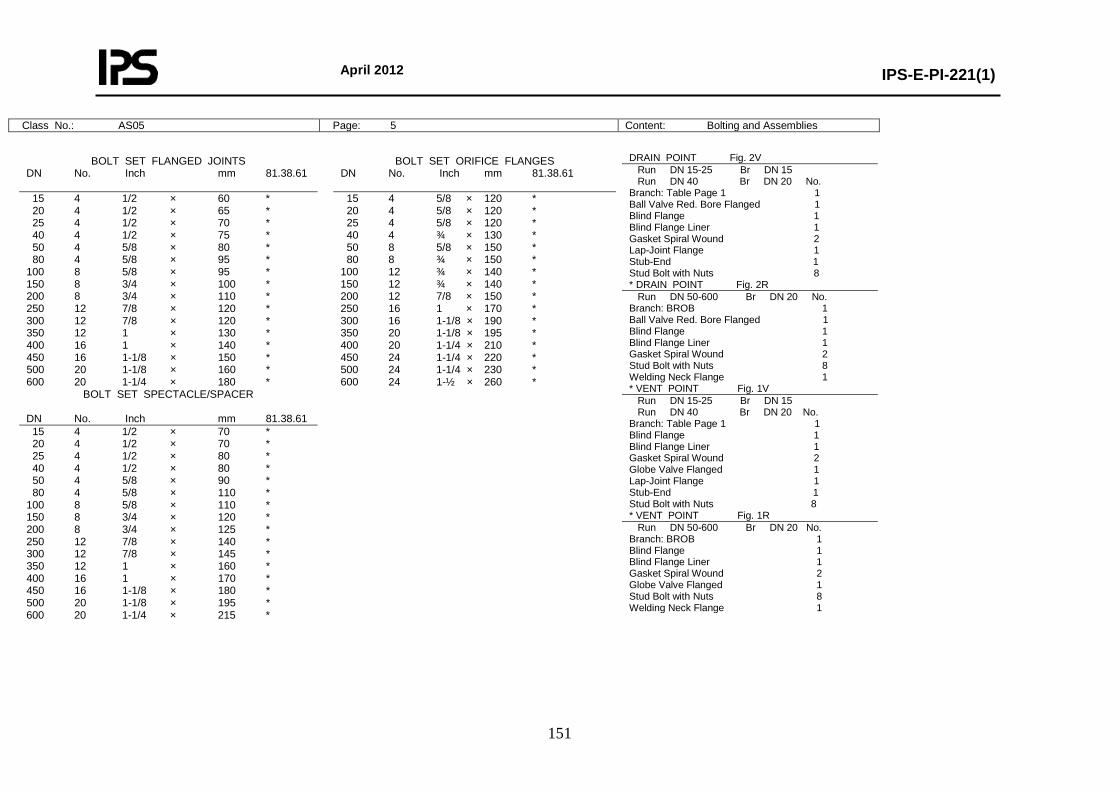
April 2012
IPS-E-PI-221(1)
151
Class No.: AS05 Page: 5 Content: Bolting and Assemblies
DRAIN POINT Fig. 2V Run DN 15-25 Br DN 15 Run DN 40 Br DN 20 No. Branch: Table Page 1 1 Ball Valve Red. Bore Flanged 1 Blind Flange 1 Blind Flange Liner 1 Gasket Spiral Wound 2 Lap-Joint Flange 1 Stub-End 1 Stud Bolt with Nuts 8 * DRAIN POINT Fig. 2R Run DN 50-600 Br DN 20 No. Branch: BROB 1 Ball Valve Red. Bore Flanged 1 Blind Flange 1 Blind Flange Liner 1 Gasket Spiral Wound 2 Stud Bolt with Nuts 8 Welding Neck Flange 1 * VENT POINT Fig. 1V Run DN 15-25 Br DN 15 Run DN 40 Br DN 20 No. Branch: Table Page 1 1 Blind Flange 1 Blind Flange Liner 1 Gasket Spiral Wound 2 Globe Valve Flanged 1 Lap-Joint Flange 1 Stub-End 1 Stud Bolt with Nuts 8 * VENT POINT Fig. 1R Run DN 50-600 Br DN 20 No. Branch: BROB 1 Blind Flange 1 Blind Flange Liner 1 Gasket Spiral Wound 2 Globe Valve Flanged 1 Stud Bolt with Nuts 8 Welding Neck Flange 1
BOLT SET FLANGED JOINTS DN No. Inch mm 81.38.61
BOLT SET ORIFICE FLANGES DN No. Inch mm 81.38.61
15 4 1/2 × 60 * 20 4 1/2 × 65 * 25 4 1/2 × 70 * 40 4 1/2 × 75 * 50 4 5/8 × 80 * 80 4 5/8 × 95 * 100 8 5/8 × 95 * 150 8 3/4 × 100 * 200 8 3/4 × 110 * 250 12 7/8 × 120 * 300 12 7/8 × 120 * 350 12 1 × 130 * 400 16 1 × 140 * 450 16 1-1/8 × 150 * 500 20 1-1/8 × 160 * 600 20 1-1/4 × 180 *
15 4 5/8 × 120 * 20 4 5/8 × 120 * 25 4 5/8 × 120 * 40 4 ¾ × 130 * 50 8 5/8 × 150 * 80 8 ¾ × 150 * 100 12 ¾ × 140 * 150 12 ¾ × 140 * 200 12 7/8 × 150 * 250 16 1 × 170 * 300 16 1-1/8 × 190 * 350 20 1-1/8 × 195 * 400 20 1-1/4 × 210 * 450 24 1-1/4 × 220 * 500 24 1-1/4 × 230 * 600 24 1-½ × 260 *
BOLT SET SPECTACLE/SPACER DN No. Inch mm 81.38.61 15 4 1/2 × 70 * 20 4 1/2 × 70 * 25 4 1/2 × 80 * 40 4 1/2 × 80 * 50 4 5/8 × 90 * 80 4 5/8 × 110 * 100 8 5/8 × 110 * 150 8 3/4 × 120 * 200 8 3/4 × 125 * 250 12 7/8 × 140 * 300 12 7/8 × 145 * 350 12 1 × 160 * 400 16 1 × 170 * 450 16 1-1/8 × 180 * 500 20 1-1/8 × 195 * 600 20 1-1/4 × 215 *
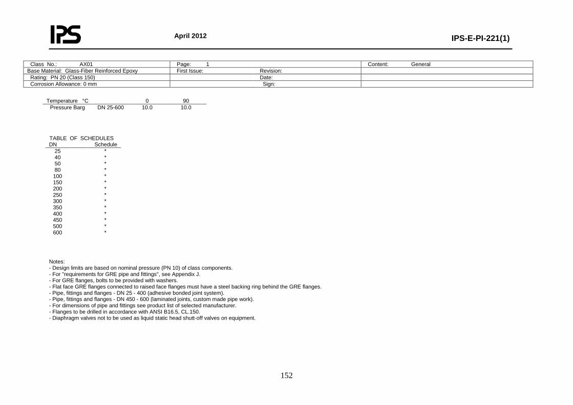
April 2012
IPS-E-PI-221(1)
152
Class No.: AX01 Page: 1 Content: General Base Material: Glass-Fiber Reinforced Epoxy First Issue: Revision: Rating: PN 20 (Class 150) Date: Corrosion Allowance: 0 mm Sign:
Temperature °C 0 90
Pressure Barg DN 25-600 10.0 10.0
Notes: - Design limits are based on nominal pressure (PN 10) of class components. - For "requirements for GRE pipe and fittings", see Appendix J. - For GRE flanges, bolts to be provided with washers. - Flat face GRE flanges connected to raised face flanges must have a steel backing ring behind the GRE flanges. - Pipe, fittings and flanges - DN 25 - 400 (adhesive bonded joint system). - Pipe, fittings and flanges - DN 450 - 600 (laminated joints, custom made pipe work). - For dimensions of pipe and fittings see product list of selected manufacturer. - Flanges to be drilled in accordance with ANSI B16.5, CL.150. - Diaphragm valves not to be used as liquid static head shutt-off valves on equipment.
TABLE OF SCHEDULES DN Schedule
25 40 50 80
100 150 200 250 300 350 400 450 500 600
* * * * * * * * * * * * * *
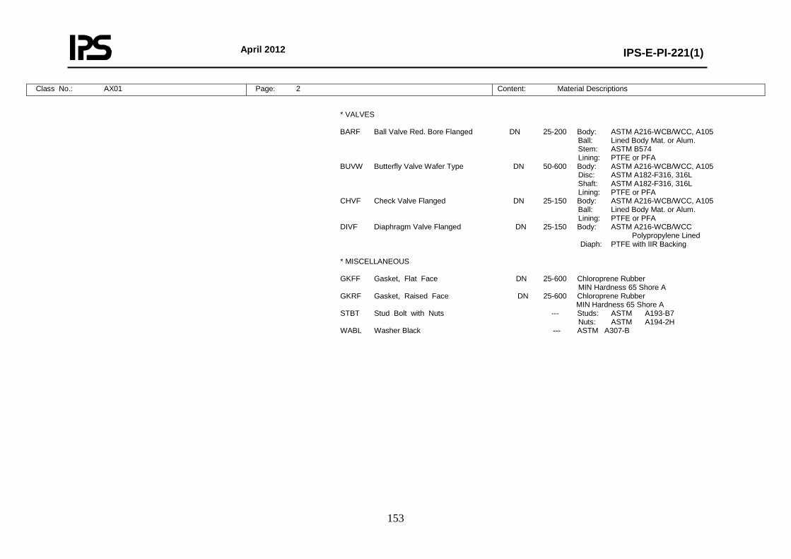
April 2012
IPS-E-PI-221(1)
153
Class No.: AX01 Page: 2 Content: Material Descriptions
* VALVES BARF Ball Valve Red. Bore Flanged DN 25-200 Body: ASTM A216-WCB/WCC, A105 Ball: Lined Body Mat. or Alum. Stem: ASTM B574 Lining: PTFE or PFA BUVW Butterfly Valve Wafer Type DN 50-600 Body: ASTM A216-WCB/WCC, A105 Disc: ASTM A182-F316, 316L Shaft: ASTM A182-F316, 316L Lining: PTFE or PFA CHVF Check Valve Flanged DN 25-150 Body: ASTM A216-WCB/WCC, A105 Ball: Lined Body Mat. or Alum. Lining: PTFE or PFA DIVF Diaphragm Valve Flanged DN 25-150 Body: ASTM A216-WCB/WCC Polypropylene Lined Diaph: PTFE with IIR Backing * MISCELLANEOUS GKFF Gasket, Flat Face DN 25-600 Chloroprene Rubber MIN Hardness 65 Shore A GKRF Gasket, Raised Face DN 25-600 Chloroprene Rubber MIN Hardness 65 Shore A STBT Stud Bolt with Nuts --- Studs: ASTM A193-B7 Nuts: ASTM A194-2H WABL Washer Black --- ASTM A307-B
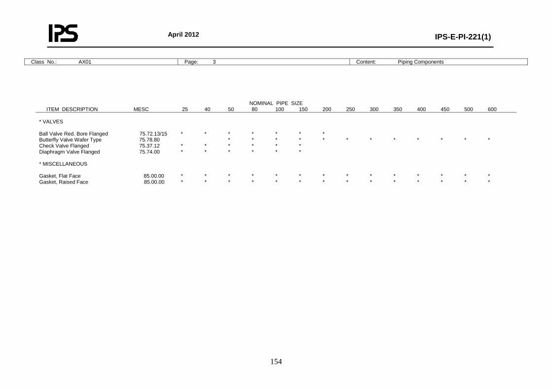
April 2012
IPS-E-PI-221(1)
154
Class No.: AX01 Page: 3 Content: Piping Components
NOMINAL PIPE SIZE ITEM DESCRIPTION MESC 25 40 50 80 100 150 200 250 300 350 400 450 500 600 * VALVES Ball Valve Red. Bore Flanged 75.72.13/15 * * * * * * * Butterfly Valve Wafer Type 75.78.80 * * * * * * * * * * * * Check Valve Flanged 75.37.12 * * * * * * Diaphragm Valve Flanged 75.74.00 * * * * * * * MISCELLANEOUS Gasket, Flat Face 85.00.00 * * * * * * * * * * * * * * Gasket, Raised Face 85.00.00 * * * * * * * * * * * * * *
April 2012
IPS-E-PI-221(1)
155
Class No.: AX01 Page: 4 Content: Reducing Piping Components
Class No.: AX01 Page: 5 Content: Bolting and Assemblies
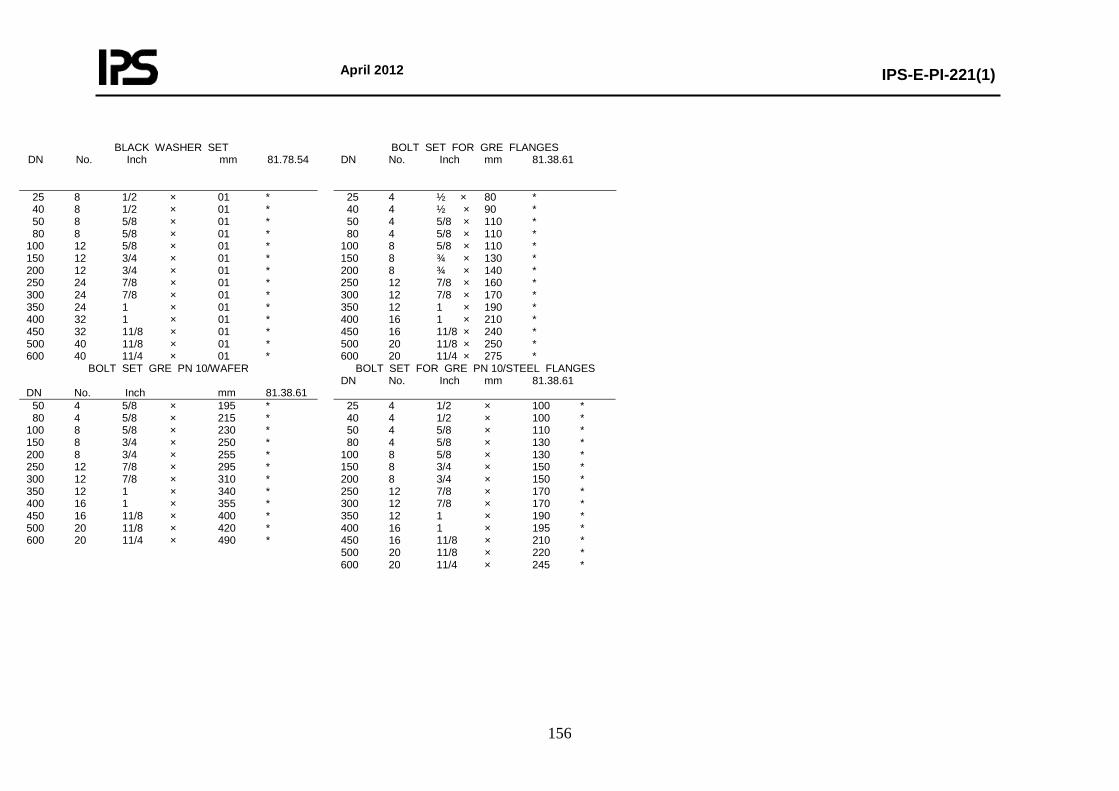
April 2012
IPS-E-PI-221(1)
156
BLACK WASHER SET DN No. Inch mm 81.78.54
BOLT SET FOR GRE FLANGES DN No. Inch mm 81.38.61
25 8 1/2 × 01 * 40 8 1/2 × 01 * 50 8 5/8 × 01 * 80 8 5/8 × 01 * 100 12 5/8 × 01 * 150 12 3/4 × 01 * 200 12 3/4 × 01 * 250 24 7/8 × 01 * 300 24 7/8 × 01 * 350 24 1 × 01 * 400 32 1 × 01 * 450 32 11/8 × 01 * 500 40 11/8 × 01 * 600 40 11/4 × 01 *
25 4 ½ × 80 * 40 4 ½ × 90 * 50 4 5/8 × 110 * 80 4 5/8 × 110 * 100 8 5/8 × 110 * 150 8 ¾ × 130 * 200 8 ¾ × 140 * 250 12 7/8 × 160 * 300 12 7/8 × 170 * 350 12 1 × 190 * 400 16 1 × 210 * 450 16 11/8 × 240 * 500 20 11/8 × 250 * 600 20 11/4 × 275 *
BOLT SET GRE PN 10/WAFER DN No. Inch mm 81.38.61
BOLT SET FOR GRE PN 10/STEEL FLANGES DN No. Inch mm 81.38.61
50 4 5/8 × 195 * 80 4 5/8 × 215 * 100 8 5/8 × 230 * 150 8 3/4 × 250 * 200 8 3/4 × 255 * 250 12 7/8 × 295 * 300 12 7/8 × 310 * 350 12 1 × 340 * 400 16 1 × 355 * 450 16 11/8 × 400 * 500 20 11/8 × 420 * 600 20 11/4 × 490 *
25 4 1/2 × 100 * 40 4 1/2 × 100 * 50 4 5/8 × 110 * 80 4 5/8 × 130 * 100 8 5/8 × 130 * 150 8 3/4 × 150 * 200 8 3/4 × 150 * 250 12 7/8 × 170 * 300 12 7/8 × 170 * 350 12 1 × 190 * 400 16 1 × 195 * 450 16 11/8 × 210 * 500 20 11/8 × 220 * 600 20 11/4 × 245 *
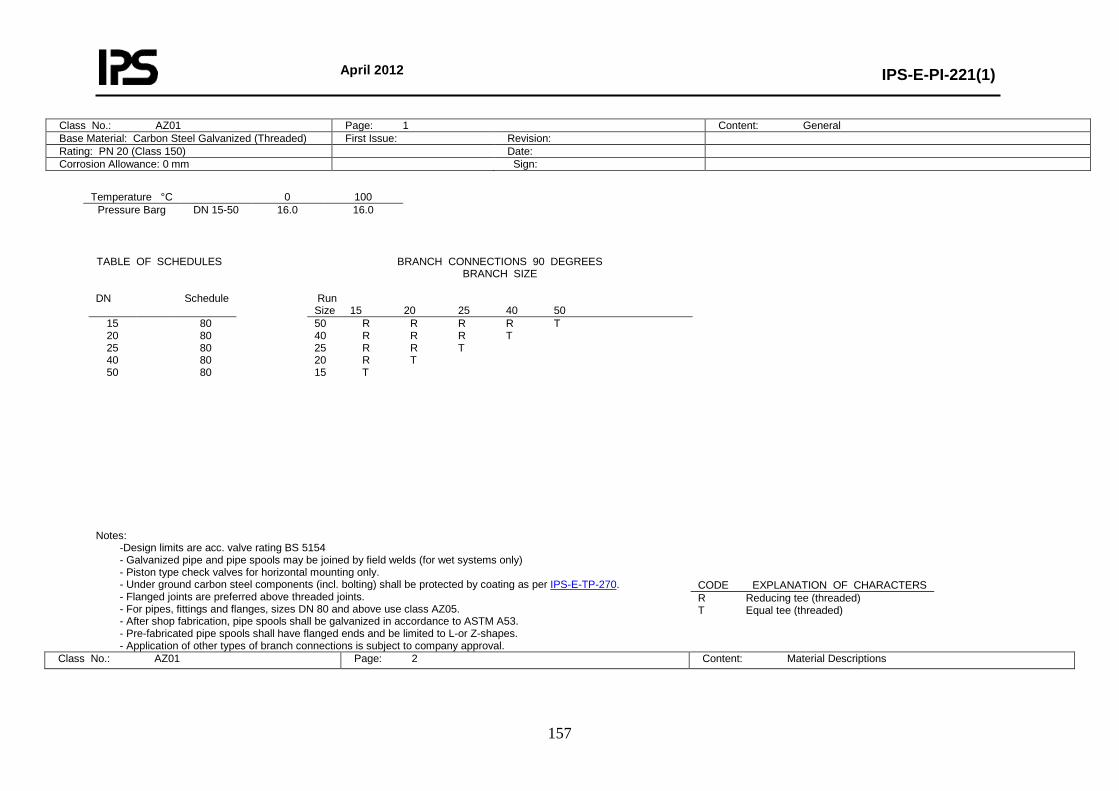
April 2012
IPS-E-PI-221(1)
157
Class No.: AZ01 Page: 1 Content: General Base Material: Carbon Steel Galvanized (Threaded) First Issue: Revision: Rating: PN 20 (Class 150) Date: Corrosion Allowance: 0 mm Sign:
Temperature °C 0 100
Pressure Barg DN 15-50 16.0 16.0
Notes:
-Design limits are acc. valve rating BS 5154 - Galvanized pipe and pipe spools may be joined by field welds (for wet systems only) - Piston type check valves for horizontal mounting only. - Under ground carbon steel components (incl. bolting) shall be protected by coating as per IPS-E-TP-270. - Flanged joints are preferred above threaded joints. - For pipes, fittings and flanges, sizes DN 80 and above use class AZ05. - After shop fabrication, pipe spools shall be galvanized in accordance to ASTM A53. - Pre-fabricated pipe spools shall have flanged ends and be limited to L-or Z-shapes. - Application of other types of branch connections is subject to company approval.
Class No.: AZ01 Page: 2 Content: Material Descriptions
TABLE OF SCHEDULES BRANCH CONNECTIONS 90 DEGREES BRANCH SIZE
DN Schedule Run
Size 15 20 25 40 50 15 20 25 40 50
80 80 80 80 80
50 R R R R T 40 R R R T 25 R R T 20 R T 15 T
CODE EXPLANATION OF CHARACTERS R Reducing tee (threaded) T Equal tee (threaded)
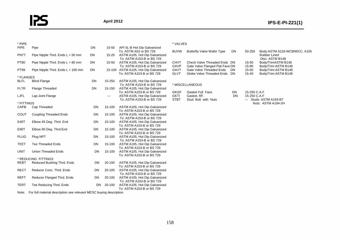
April 2012
IPS-E-PI-221(1)
158
* PIPE PIPE Pipe DN 15-50 API 5L-B Hot Dip Galvanized To: ASTM A53 or BS 729 PNTT Pipe Nipple Thrd. Ends L = 50 mm DN 15-25 ASTM A105, Hot Dip Galvanized To: ASTM A153-B or BS 729 PT80 Pipe Nipple Thrd. Ends L = 80 mm DN 15-50 ASTM A105, Hot Dip Galvanized To: ASTM A153-B or BS 729 PT99 Pipe Nipple Thrd. Ends L = 100 mm DN 15-100 ASTM A105, Hot Dip Galvanized To: ASTM A153-B or BS 729 * FLANGES BLFL Blind Flange DN 15-250 ASTM A105, Hot Dip Galvanized To: ASTM A153-B or BS 729 FLTR Flange Threaded DN 15-150 ASTM A105, Hot Dip Galvanized To: ASTM A153-B or BS 729 LJFL Lap-Joint Flange --- ASTM A105, Hot Dip Galvanized To: ASTM A153-B or BS 729 * FITTINGS CAPB Cap Threaded DN 15-100 ASTM A105, Hot Dip Galvanized To: ASTM A153-B or BS 729 COUT Coupling Threaded Ends DN 15-100 ASTM A105, Hot Dip Galvanized To: ASTM A153-B or BS 729 E45T Elbow 45 Deg. Thrd. End DN 15-100 ASTM A105, Hot Dip Galvanized To: ASTM A153-B or BS 729 E90T Elbow 90 Deg. Thrd.End DN 15-100 ASTM A105, Hot Dip Galvanized To: ASTM A153-B or BS 729 PLUG Plug NPT DN 15-100 ASTM A105, Hot Dip Galvanized To: ASTM A153-B or BS 729 TEET Tee Threaded Ends DN 15-100 ASTM A105, Hot Dip Galvanized To: ASTM A153-B or BS 729 UNIT Union Threaded Ends DN 15-100 ASTM A105, Hot Dip Galvanized To: ASTM A153-B or BS 729 * REDUCING FITTINGS REBT Reduced Bushing Thrd. Ends DN 20-100 ASTM A105, Hot Dip Galvanized To: ASTM A153-B or BS 729 RECT Reducer Conc. Thrd. Ends DN 20-100 ASTM A105, Hot Dip Galvanized To: ASTM A153-B or BS 729 REFT Reducer Flanged Thrd. Ends DN 20-100 ASTM A105, Hot Dip Galvanized To: ASTM A153-B or BS 729 TERT Tee Reducing Thrd. Ends DN 20-100 ASTM A105, Hot Dip Galvanized To: ASTM A153-B or BS 729 Note: For full material description see relevant MESC buying description.
* VALVES BUVW Butterfly Valve Wafer Type DN 50-250 Body:ASTM A216-WCB/WCC, A105 Rubber Lined Disc: ASTM B148 CHVT Check Valve Threaded Ends DN 15-50 Body/TrimASTM B148 GAVP Gate Valve Flanged Flat Face DN 15-80 Body/Trim:ASTM B148 GAVT Gate Valve Threaded Ends DN 15-50 Body/Trim:ASTM B148 GLVT Globe Valve Threaded Ends DN 15-40 Body/Trim:ASTM B148 * MISCELLANEOUS GKGF Gasket Full Face DN 15-250 C.A.F GKTI Gasket, RF. DN 15-250 C.A.F STBT Stud Bolt with Nuts --- Studs: ASTM A193-B7 Nuts: ASTM A194-2H
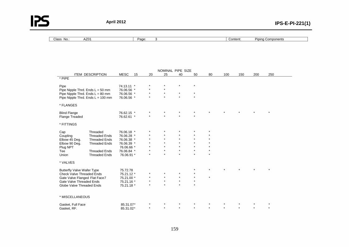
April 2012
IPS-E-PI-221(1)
159
Class No.: AZ01 Page: 3 Content: Piping Components
NOMINAL PIPE SIZE ITEM DESCRIPTION MESC 15 20 25 40 50 80 100 150 200 250 * PIPE Pipe 74.13.11 * * * * * Pipe Nipple Thrd. Ends L = 50 mm 76.06.56 * * * Pipe Nipple Thrd. Ends L = 80 mm 76.06.56 * * * * * Pipe Nipple Thrd. Ends L = 100 mm 76.06.56 * * * * * * FLANGES Blind Flange 76.62.15 * * * * * * * * * * Flange Treaded 76.62.61 * * * * * * FITTINGS Cap Threaded 76.06.18 * * * * * * Coupling Threaded Ends 76.06.28 * * * * * * Elbow 45 Deg. Threaded Ends 76.06.38 * * * * * * Elbow 90 Deg. Threaded Ends 76.06.39 * * * * * * Plug NPT 76.06.66 * * * * * * Tee Threaded Ends 76.06.84 * * * * * * Union Threaded Ends 76.06.91 * * * * * * * VALVES Butterfly Valve Wafer Type 75.72.78 * * * * * * Check Valve Threaded Ends 75.21.12 * * * * * Gate Valve Flanged Flat Face 7 75.21.00 * * * * * * Gate Valve Threaded Ends 75.21.16 * * * * * Globe Valve Threaded Ends 75.21.18 * * * * * * MISCELLANEOUS Gasket, Full Face 85.31.07 * * * * * * * * * * Gasket, RF. 85.31.02 * * * * * * * * * *
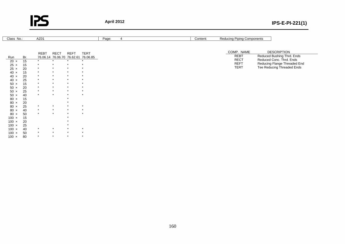
April 2012
IPS-E-PI-221(1)
160
Class No.: AZ01 Page: 4 Content: Reducing Piping Components
REBT RECT REFT TERT Run Br. 76.06.14 76.06.70 76.62.61 76.06.85 20 × 15 * * * * 25 × 15 * * * * 25 × 20 * * * * 40 × 15 * * * * 40 × 20 * * * * 40 × 25 * * * * 50 × 15 * * * * 50 × 20 * * * * 50 × 25 * * * * 50 × 40 * * * * 80 × 15 * 80 × 20 * 80 × 25 * * * * 80 × 40 * * * * 80 × 50 * * * * 100 × 15 * 100 × 20 * 100 × 25 * 100 × 40 * * * * 100 × 50 * * * * 100 × 80 * * * *
COMP. NAME DESCRIPTION REBT Reduced Bushing Thrd. Ends RECT Reduced Conc. Thrd. Ends REFT Reducing Flange Threaded End TERT Tee Reducing Threaded Ends

April 2012
IPS-E-PI-221(1)
161
Class No.: AS05 Page: 5 Content: Bolting and Assemblies
* DRAIN POINT Fig. 0C Run DN 15-25 Br DN 15 No. Branch: Table Page 1 1 Cap Threaded 1 Gate Valve Threaded Ends 1 Pipe Nipple Thrd. Ends L = 50 mm 2 * DRAIN POINT Fig. 0C Run DN 40-50 Br DN 20 No. Branch: Table Page 1 1 Cap Threaded 1 Gate Valve Threaded Ends 1 Pipe Nipple Thrd. Ends L = 50 mm 2 * VENT POINT Fig. 1C Run DN 15-25 Br DN 15 No. Branch: Table Page 1 1 Cap Threaded 1 Globe Valve Threaded Ends 1 Pipe Nipple Thrd. Ends L = 50 mm 2 * VENT POINT Fig. 1C Run DN 40-50 Br DN 20 No. Branch: Table Page 1 1 Cap Threaded 1 Globe Valve Threaded Ends 1 Pipe Nipple Thrd. Ends L = 50 mm 2
BOLTS.WA. LUG BUTTFY VALVE DN No. Inch mm 81.38.61 15 4 5/8 × 130 * 80 4 5/8 × 150 * 100 8 5/8 × 150 * 150 8 3/4 × 160 * 200 8 3/4 × 170 * 250 12 7/8 × 190 *
BOLT SET FLANGED JOINTS DN No. Inch mm 81.38.61 15 4 1/2 × 60 * 20 4 1/2 × 70 * 25 4 1/2 × 70 * 40 4 1/2 × 80 * 50 4 5/8 × 80 * 80 4 5/8 × 100 * 100 8 5/8 × 100 * 150 8 3/4 × 100 * 200 8 3/4 × 110 * 250 12 7/8 × 120 * BOLT SET SPECTACLE/SPACER DN No. Inch mm 81.38.61 15 4 1/2 × 70 * 20 4 1/2 × 70 * 25 4 1/2 × 80 * 40 4 1/2 × 80 * 50 4 5/8 × 90 * 80 4 5/8 × 110 * 100 8 5/8 × 110 * 150 8 3/4 × 120 * 200 8 3/4 × 130 * 250 12 7/8 × 140 *
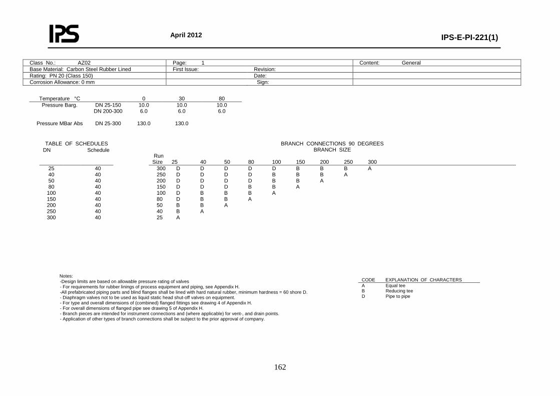
April 2012
IPS-E-PI-221(1)
162
Class No.: AZ02 Page: 1 Content: General Base Material: Carbon Steel Rubber Lined First Issue: Revision: Rating: PN 20 (Class 150) Date: Corrosion Allowance: 0 mm Sign:
Temperature °C 0 30 80 Pressure Barg.
Pressure MBar Abs
DN 25-150 DN 200-300
DN 25-300
10.0 6.0
130.0
10.0 6.0
130.0
10.0 6.0
Notes:
-Design limits are based on allowable pressure rating of valves - For requirements for rubber linings of process equipment and piping, see Appendix H. -All prefabricated piping parts and blind flanges shall be lined with hard natural rubber, minimum hardness = 60 shore D. - Diaphragm valves not to be used as liquid static head shut-off valves on equipment. - For type and overall dimensions of (combined) flanged fittings see drawing 4 of Appendix H. - For overall dimensions of flanged pipe see drawing 5 of Appendix H. - Branch pieces are intended for instrument connections and (where applicable) for vent-, and drain points. - Application of other types of branch connections shall be subject to the prior approval of company.
TABLE OF SCHEDULES BRANCH CONNECTIONS 90 DEGREES BRANCH SIZE
Run Size 25 40 50 80 100 150 200 250 300
DN Schedule
25 40 50 80
100 150 200 250 300
40 40 40 40 40 40 40 40 40
300 D D D D D B B B A 250 D D D D B B B A 200 D D D D B B A 150 D D D B B A 100 D B B B A 80 D B B A 50 B B A 40 B A 25 A
CODE EXPLANATION OF CHARACTERS A Equal tee B Reducing tee D Pipe to pipe
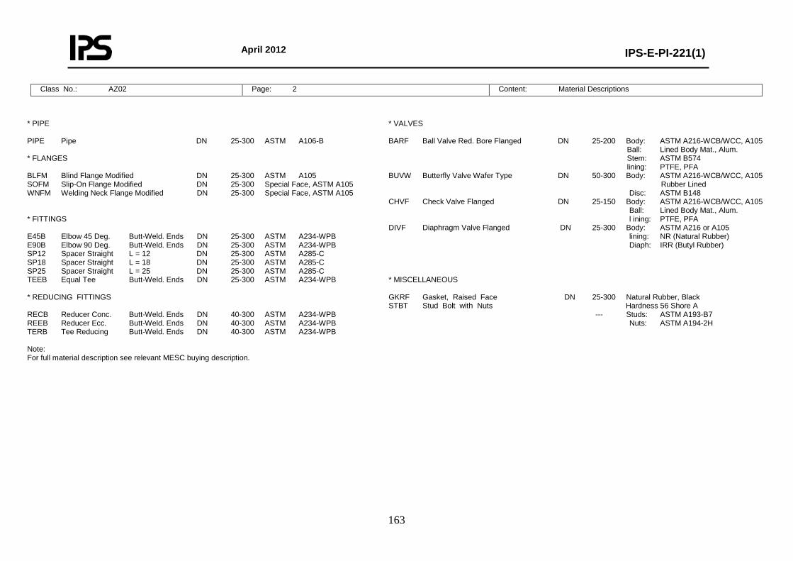
April 2012
IPS-E-PI-221(1)
163
Class No.: AZ02 Page: 2 Content: Material Descriptions
* PIPE PIPE Pipe DN 25-300 ASTM A106-B * FLANGES BLFM Blind Flange Modified DN 25-300 ASTM A105 SOFM Slip-On Flange Modified DN 25-300 Special Face, ASTM A105 WNFM Welding Neck Flange Modified DN 25-300 Special Face, ASTM A105 * FITTINGS E45B Elbow 45 Deg. Butt-Weld. Ends DN 25-300 ASTM A234-WPB E90B Elbow 90 Deg. Butt-Weld. Ends DN 25-300 ASTM A234-WPB SP12 Spacer Straight L = 12 DN 25-300 ASTM A285-C SP18 Spacer Straight L = 18 DN 25-300 ASTM A285-C SP25 Spacer Straight L = 25 DN 25-300 ASTM A285-C TEEB Equal Tee Butt-Weld. Ends DN 25-300 ASTM A234-WPB * REDUCING FITTINGS RECB Reducer Conc. Butt-Weld. Ends DN 40-300 ASTM A234-WPB REEB Reducer Ecc. Butt-Weld. Ends DN 40-300 ASTM A234-WPB TERB Tee Reducing Butt-Weld. Ends DN 40-300 ASTM A234-WPB Note: For full material description see relevant MESC buying description.
* VALVES BARF Ball Valve Red. Bore Flanged DN 25-200 Body: ASTM A216-WCB/WCC, A105 Ball: Lined Body Mat., Alum. Stem: ASTM B574 lining: PTFE, PFA BUVW Butterfly Valve Wafer Type DN 50-300 Body: ASTM A216-WCB/WCC, A105 Rubber Lined Disc: ASTM B148 CHVF Check Valve Flanged DN 25-150 Body: ASTM A216-WCB/WCC, A105 Ball: Lined Body Mat., Alum. l ining: PTFE, PFA DIVF Diaphragm Valve Flanged DN 25-300 Body: ASTM A216 or A105 lining: NR (Natural Rubber) Diaph: IRR (Butyl Rubber) * MISCELLANEOUS GKRF Gasket, Raised Face DN 25-300 Natural Rubber, Black STBT Stud Bolt with Nuts Hardness 56 Shore A --- Studs: ASTM A193-B7 Nuts: ASTM A194-2H
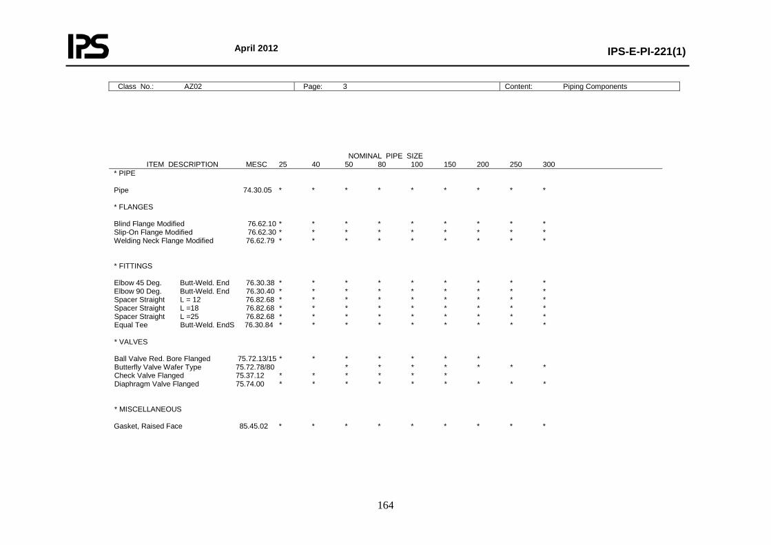
April 2012
IPS-E-PI-221(1)
164
Class No.: AZ02 Page: 3 Content: Piping Components
NOMINAL PIPE SIZE ITEM DESCRIPTION MESC 25 40 50 80 100 150 200 250 300 * PIPE Pipe 74.30.05 * * * * * * * * * * FLANGES Blind Flange Modified 76.62.10 * * * * * * * * * Slip-On Flange Modified 76.62.30 * * * * * * * * * Welding Neck Flange Modified 76.62.79 * * * * * * * * * * FITTINGS Elbow 45 Deg. Butt-Weld. End 76.30.38 * * * * * * * * * Elbow 90 Deg. Butt-Weld. End 76.30.40 * * * * * * * * * Spacer Straight L = 12 76.82.68 * * * * * * * * * Spacer Straight L =18 76.82.68 * * * * * * * * * Spacer Straight L =25 76.82.68 * * * * * * * * * Equal Tee Butt-Weld. EndS 76.30.84 * * * * * * * * * * VALVES Ball Valve Red. Bore Flanged 75.72.13/15 * * * * * * * Butterfly Valve Wafer Type 75.72.78/80 * * * * * * * Check Valve Flanged 75.37.12 * * * * * * Diaphragm Valve Flanged 75.74.00 * * * * * * * * * * MISCELLANEOUS Gasket, Raised Face 85.45.02 * * * * * * * * *
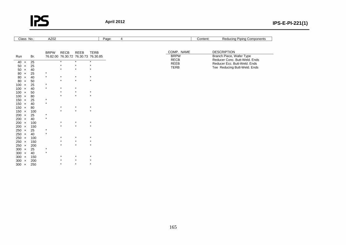
April 2012
IPS-E-PI-221(1)
165
Class No.: AZ02 Page: 4 Content: Reducing Piping Components
BRPW RECB REEB TERB Run Br. 76.82.00 76.30.72 76.30.73 76.30.85
40 × 25 * * * 50 × 25 * * * 50 × 40 * * * 80 × 25 * 80 × 40 * * * * 80 × 50 * * * 100 × 25 * 100 × 40 * * * 100 × 50 * * * 100 × 80 * * * 150 × 25 * 150 × 40 * 150 × 80 * * * 150 × 100 * * * 200 × 25 * 200 × 40 * 200 × 100 * * * 200 × 150 * * * 250 × 25 * 250 × 40 * 250 × 100 * * * 250 × 150 * * * 250 × 200 * * * 300 × 25 * 300 × 40 * 300 × 150 * * * 300 × 200 * * * 300 × 250 * * *
COMP. NAME DESCRIPTION BRPW Branch Piece, Wafer Type RECB Reducer Conc. Butt-Weld. Ends REEB Reducer Ecc. Butt-Weld. Ends TERB Tee Reducing Butt-Weld. Ends
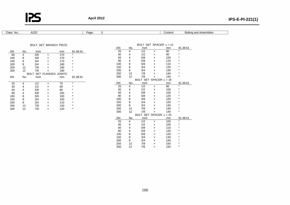
April 2012
IPS-E-PI-221(1)
166
Class No.: AZ02 Page: 5 Content: Bolting and Assemblies
BOLT SET BRANCH PIECE
DN No. Inch mm 81.38.61 80 4 5/8 × 170 * 100 8 5/8 × 170 * 150 8 3/4 × 170 * 200 8 3/4 × 180 * 250 12 7/8 × 190 * 300 12 7/8 × 190 *
BOLT SET FLANGED JOINTS DN No. Inch mm 81.38.61 25 4 1/2 × 70 * 40 4 1/2 × 80 * 50 4 5/8 × 80 * 80 4 5/8 × 100 * 100 8 5/8 × 100 * 150 8 3/4 × 100 * 200 8 3/4 × 110 * 250 12 7/8 × 120 * 300 12 7/8 × 120 *
BOLT SET SPACER L = 12 DN No. Inch mm 81.38.61 25 4 1/2 × 90 * 40 4 1/2 × 90 * 50 4 5/8 × 100 * 80 4 5/8 × 110 * 100 8 5/8 × 110 * 150 8 3/4 × 120 * 200 8 3/4 × 130 * 250 12 7/8 × 140 * 300 12 7/8 × 140 *
BOLT SET SPACER L = 18 DN No. Inch mm 81.38.61 25 4 1/2 × 90 * 40 4 1/2 × 100 * 50 4 5/8 × 100 * 80 4 5/8 × 120 * 100 8 5/8 × 120 * 150 8 3/4 × 120 * 200 8 3/4 × 130 * 250 12 7/8 × 140 * 300 12 7/8 × 140 *
BOLT SET SPACER L = 25 DN No. Inch mm 81.38.61 25 4 1/2 × 100 * 40 4 1/2 × 100 * 50 4 5/8 × 110 * 80 4 5/8 × 120 * 100 8 5/8 × 120 * 150 8 3/4 × 130 * 200 8 3/4 × 140 * 250 12 7/8 × 150 * 300 12 7/8 × 150 *
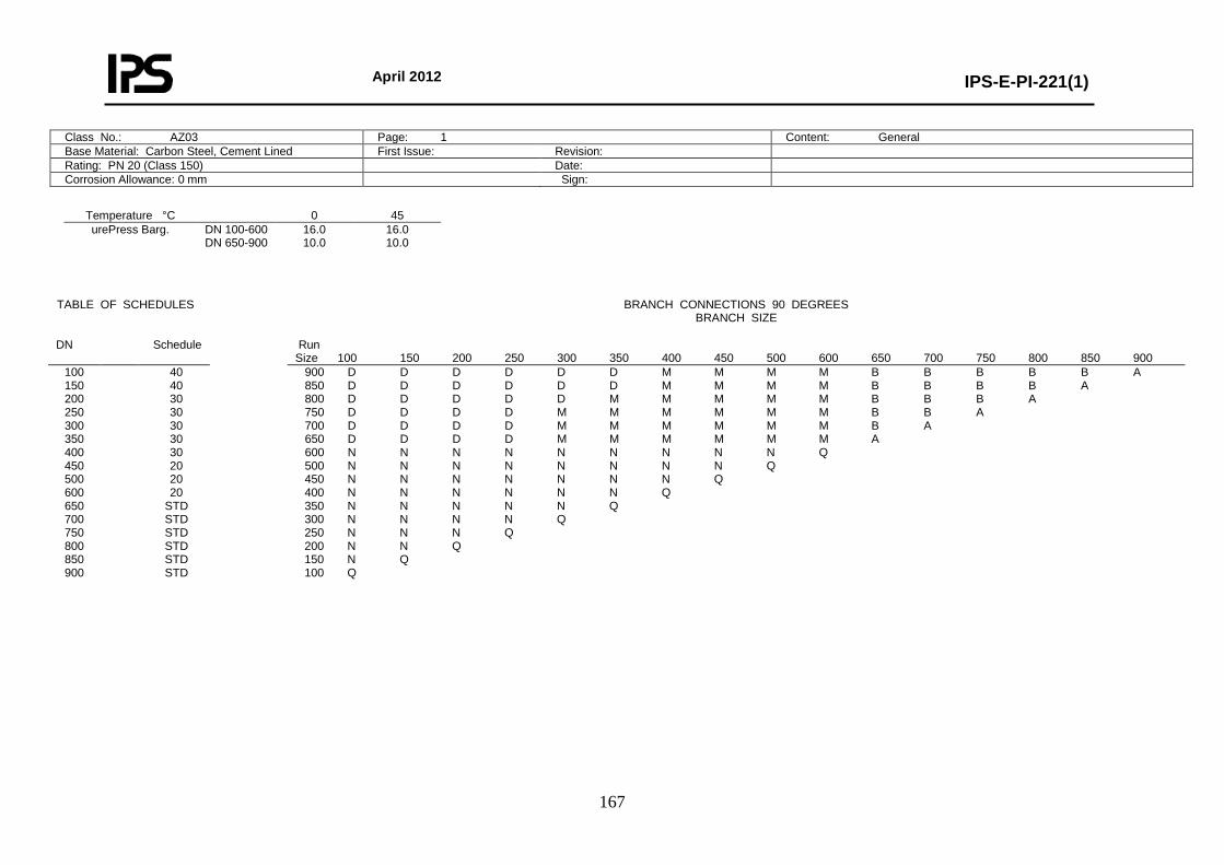
April 2012
IPS-E-PI-221(1)
167
Class No.: AZ03 Page: 1 Content: General Base Material: Carbon Steel, Cement Lined First Issue: Revision: Rating: PN 20 (Class 150) Date: Corrosion Allowance: 0 mm Sign:
Temperature °C 0 45 urePress Barg.
DN 100-600 DN 650-900
16.0 10.0
16.0 10.0
TABLE OF SCHEDULES BRANCH CONNECTIONS 90 DEGREES BRANCH SIZE
DN Schedule Run
Size 100 150 200 250 300 350 400 450 500 600 650 700 750 800 850 900 100 150 200 250 300 350 400 450 500 600 650 700 750 800 850 900
40 40 30 30 30 30 30 20 20 20
STD STD STD STD STD STD
900 D D D D D D M M M M B B B B B A 850 D D D D D D M M M M B B B B A 800 D D D D D M M M M M B B B A 750 D D D D M M M M M M B B A 700 D D D D M M M M M M B A 650 D D D D M M M M M M A 600 N N N N N N N N N Q 500 N N N N N N N N Q 450 N N N N N N N Q 400 N N N N N N Q 350 N N N N N Q 300 N N N N Q 250 N N N Q 200 N N Q 150 N Q 100 Q
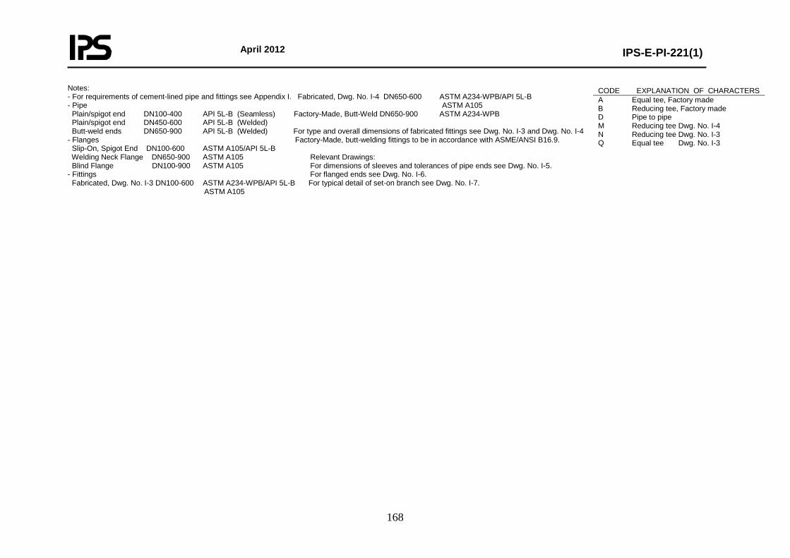
April 2012
IPS-E-PI-221(1)
168
Notes: - For requirements of cement-lined pipe and fittings see Appendix I. Fabricated, Dwg. No. I-4 DN650-600 ASTM A234-WPB/API 5L-B - Pipe ASTM A105 Plain/spigot end DN100-400 API 5L-B (Seamless) Factory-Made, Butt-Weld DN650-900 ASTM A234-WPB Plain/spigot end DN450-600 API 5L-B (Welded) Butt-weld ends DN650-900 API 5L-B (Welded) For type and overall dimensions of fabricated fittings see Dwg. No. I-3 and Dwg. No. I-4 - Flanges Factory-Made, butt-welding fittings to be in accordance with ASME/ANSI B16.9. Slip-On, Spigot End DN100-600 ASTM A105/API 5L-B Welding Neck Flange DN650-900 ASTM A105 Relevant Drawings: Blind Flange DN100-900 ASTM A105 For dimensions of sleeves and tolerances of pipe ends see Dwg. No. I-5. - Fittings For flanged ends see Dwg. No. I-6. Fabricated, Dwg. No. I-3 DN100-600 ASTM A234-WPB/API 5L-B For typical detail of set-on branch see Dwg. No. I-7. ASTM A105
CODE EXPLANATION OF CHARACTERS A Equal tee, Factory made B Reducing tee, Factory made D Pipe to pipe M Reducing tee Dwg. No. I-4 N Reducing tee Dwg. No. I-3 Q Equal tee Dwg. No. I-3

April 2012
IPS-E-PI-221(1)
169
Class No.: AZ03 Page: 2 Content: Material Descriptions
* FLANGES BLFL Blind Flange DN 100-900 ASTM A105 * FITTINGS TEEB Equal Tee Butt-Weld. Ends DN 100-900 ASTM A234-WPB * REDUCING FITTINGS TERB Tee Reducing Butt-Weld. Ends DN 150-900 ASTM A234-WPB Note: For full material description see relevant MESC buying description. Carbon steel blind flanges to be protected as follow: * Blast cleaning to SA 2½ * 400 mM (MIN) Epoxy coal tar paint.
* VALVES BUVW Butterfly Valve Wafer Type DN 100-900 Body: ASTM A216-WCB/WCC, A105 Rubber Lined Disc: ASTM B148 CHWL Dual PL. Check Valve Wafer Lug DN 100-900 Body: ASTM B148 Int: ASTM B148/NBR * MISCELLANEOUS GKFC Gasket, Flat Face DN 100-600 Chloroprene Rubber MIN Hardmess 70.5 Shore A GKRC Gasket, Raised Face DN 100-900 Chloroprene Rubber MIN Hardmess 70.5 Shore A STBT Stud Bolt with Nuts --- Studs: ASTM A193-B7 Nuts: ASTM A194-2H
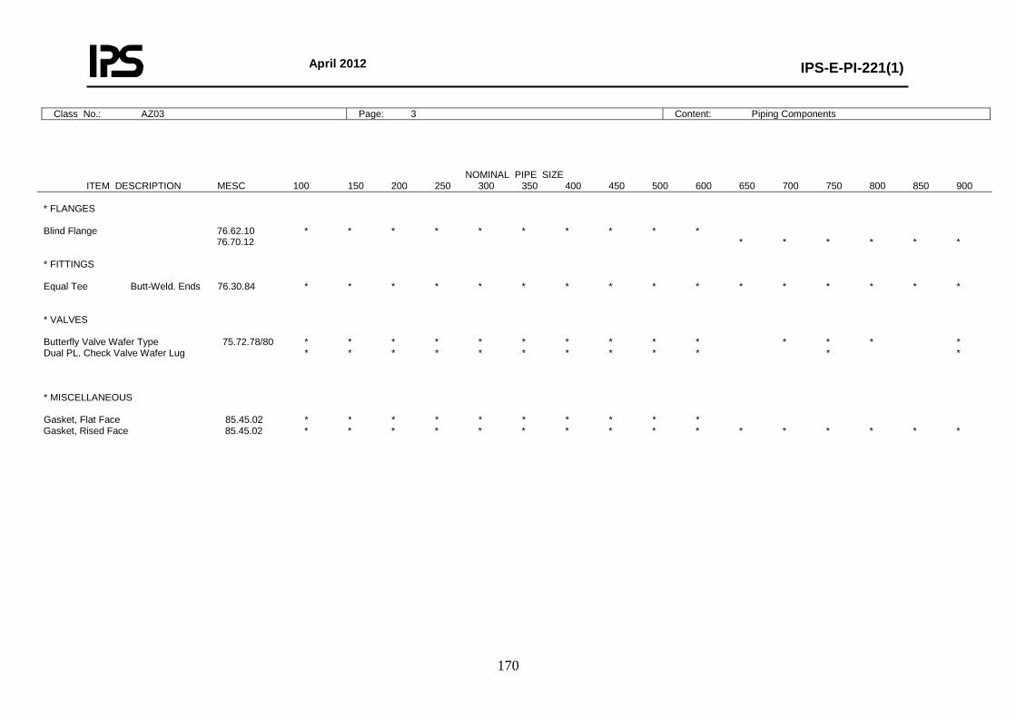
April 2012
IPS-E-PI-221(1)
170
Class No.: AZ03 Page: 3 Content: Piping Components
NOMINAL PIPE SIZE ITEM DESCRIPTION MESC 100 150 200 250 300 350 400 450 500 600 650 700 750 800 850 900 * FLANGES Blind Flange 76.62.10 * * * * * * * * * * 76.70.12 * * * * * * * FITTINGS Equal Tee Butt-Weld. Ends 76.30.84 * * * * * * * * * * * * * * * * * VALVES Butterfly Valve Wafer Type 75.72.78/80 * * * * * * * * * * * * * * Dual PL. Check Valve Wafer Lug * * * * * * * * * * * * * MISCELLANEOUS Gasket, Flat Face 85.45.02 * * * * * * * * * * Gasket, Rised Face 85.45.02 * * * * * * * * * * * * * * * *
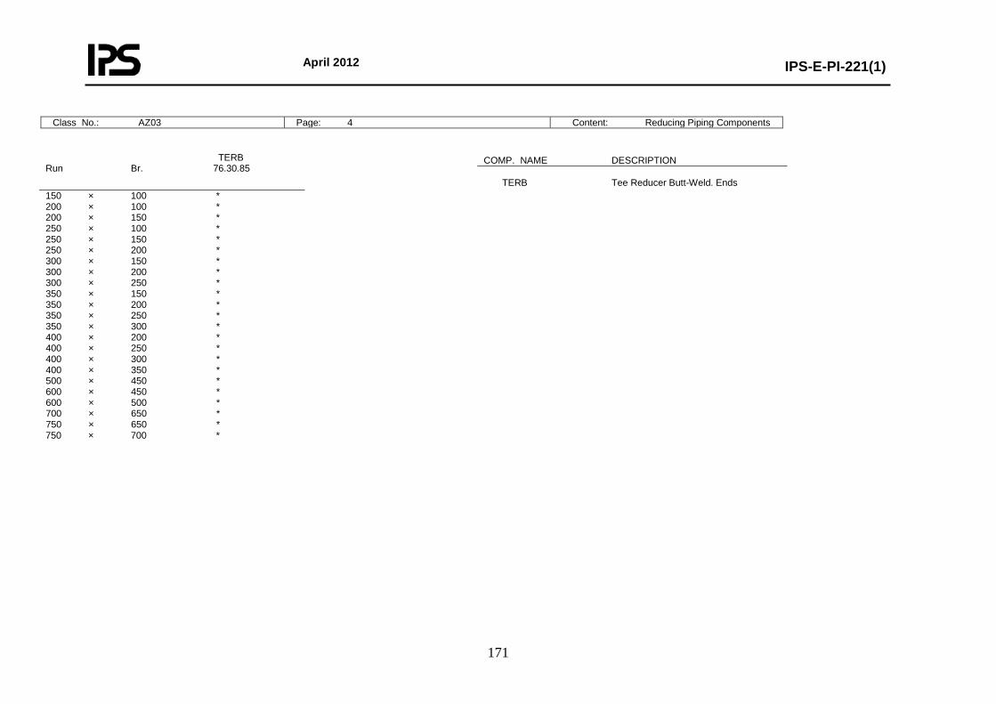
April 2012
IPS-E-PI-221(1)
171
Class No.: AZ03 Page: 4 Content: Reducing Piping Components
TERB Run Br. 76.30.85
150 × 100 * 200 × 100 * 200 × 150 * 250 × 100 * 250 × 150 * 250 × 200 * 300 × 150 * 300 × 200 * 300 × 250 * 350 × 150 * 350 × 200 * 350 × 250 * 350 × 300 * 400 × 200 * 400 × 250 * 400 × 300 * 400 × 350 * 500 × 450 * 600 × 450 * 600 × 500 * 700 × 650 * 750 × 650 * 750 × 700 *
COMP. NAME DESCRIPTION TERB Tee Reducer Butt-Weld. Ends
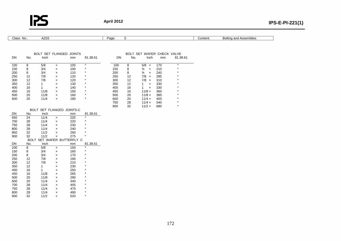
April 2012
IPS-E-PI-221(1)
172
Class No.: AZ03 Page: 5 Content: Bolting and Assemblies
BOLT SET FLANGED JOINTS DN No. Inch mm 81.38.61
BOLT SET WAFER CHECK VALVE DN No. Inch mm 81.38.61
100 8 5/8 × 100 * 150 8 3/4 × 100 * 200 8 3/4 × 110 * 250 12 7/8 × 120 * 300 12 7/8 × 120 * 350 12 1 × 130 * 400 16 1 × 140 * 450 16 11/8 × 150 * 500 20 11/8 × 160 * 600 20 11/4 × 180 *
100 8 5/8 × 170 * 150 8 ¾ × 210 * 200 8 ¾ × 240 * 250 12 7/8 × 285 * 300 12 7/8 × 310 * 350 12 1 × 330 * 400 16 1 × 330 * 450 16 11/8 × 360 * 500 20 11/8 × 385 * 600 20 11/4 × 400 * 750 28 11/4 × 540 * 900 32 11/2 × 680 *
BOLT SET FLANGED JOINTS-C DN No. Inch mm 81.38.61
650 24 11/4 × 220 * 700 28 11/4 × 220 * 750 28 11/4 × 230 * 800 28 11/4 × 240 * 850 32 11/2 × 260 * 900 32 11/2 × 275 *
BOLT SET WAFER BUTTERFLY C DN No. Inch mm 81.38.61
100 8 5/8 × 150 * 150 8 3/4 × 160 * 200 8 3/4 × 170 * 250 12 7/8 × 190 * 300 12 7/8 × 210 * 350 12 1 × 230 * 400 16 1 × 250 * 450 16 11/8 × 265 * 500 20 11/8 × 290 * 600 20 11/4 × 340 * 700 28 11/4 × 455 * 750 28 11/4 × 470 * 800 28 11/4 × 490 * 900 32 11/2 × 520 *
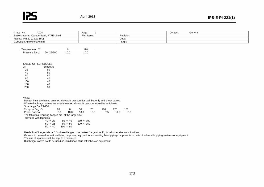
April 2012
IPS-E-PI-221(1)
173
Class No.: AZ04 Page: 1 Content: General Base Material: Carbon Steel, PTFE-Lined First Issue: Revision: Rating: PN 20 (Class 150) Date: Corrosion Allowance: 0 mm Sign:
Temperature °C 0 190
Pressure Barg DN 25-200 10.0 10.0
Notes: - Design limits are based on max. allowable pressure for ball, butterfly and check valves. * Where diaphragm valves are used the max. allowable pressure would be as follows: Size range DN 25-150. Temp. in Deg. C- 20 0 50 75 100 120 150 Press. Bar Ga. 10.0 10.0 10.0 10.0 7.5 6.5 5.0 - The following reducing flanges are, at the-large side- provided with tapholes: 40 × 25 80 × 40 150 × 100 50 × 25 80 × 50 200 × 150 50 × 40 100 × 80 - Use boltset "Large side tap" for these flanges. Use boltset "large side fl.", for all other size combinations. - Gaskets to be used for re-installation purposes only, and for connecting lined piping components to parts of vulnerable piping systems or equipment. - The use of spacers shall be kept to a minimum. - Diaphragm valves not to be used as liquid head shutt-off valves on equipment.
TABLE OF SCHEDULES DN Schedule
25 40 50 80
100 150 200
80 80 80 40 40 40 30
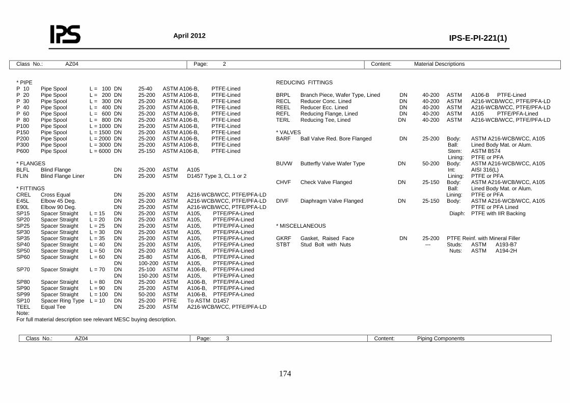
April 2012
IPS-E-PI-221(1)
174
Class No.: AZ04 Page: 2 Content: Material Descriptions
* PIPE P 10 Pipe Spool L = 100 DN 25-40 ASTM A106-B, PTFE-Lined P 20 Pipe Spool L = 200 DN 25-200 ASTM A106-B, PTFE-Lined P 30 Pipe Spool L = 300 DN 25-200 ASTM A106-B, PTFE-Lined P 40 Pipe Spool L = 400 DN 25-200 ASTM A106-B, PTFE-Lined P 60 Pipe Spool L = 600 DN 25-200 ASTM A106-B, PTFE-Lined P 80 Pipe Spool L = 800 DN 25-200 ASTM A106-B, PTFE-Lined P100 Pipe Spool L = 1000 DN 25-200 ASTM A106-B, PTFE-Lined P150 Pipe Spool L = 1500 DN 25-200 ASTM A106-B, PTFE-Lined P200 Pipe Spool L = 2000 DN 25-200 ASTM A106-B, PTFE-Lined P300 Pipe Spool L = 3000 DN 25-200 ASTM A106-B, PTFE-Lined P600 Pipe Spool L = 6000 DN 25-150 ASTM A106-B, PTFE-Lined * FLANGES BLFL Blind Flange DN 25-200 ASTM A105 FLIN Blind Flange Liner DN 25-200 ASTM D1457 Type 3, CL.1 or 2 * FITTINGS CREL Cross Equal DN 25-200 ASTM A216-WCB/WCC, PTFE/PFA-LD E45L Elbow 45 Deg. DN 25-200 ASTM A216-WCB/WCC, PTFE/PFA-LD E90L Elbow 90 Deg. DN 25-200 ASTM A216-WCB/WCC, PTFE/PFA-LD SP15 Spacer Straight L = 15 DN 25-200 ASTM A105, PTFE/PFA-Lined SP20 Spacer Straight L = 20 DN 25-200 ASTM A105, PTFE/PFA-Lined SP25 Spacer Straight L = 25 DN 25-200 ASTM A105, PTFE/PFA-Lined SP30 Spacer Straight L = 30 DN 25-200 ASTM A105, PTFE/PFA-Lined SP35 Spacer Straight L = 35 DN 25-200 ASTM A105, PTFE/PFA-Lined SP40 Spacer Straight L = 40 DN 25-200 ASTM A105, PTFE/PFA-Lined SP50 Spacer Straight L = 50 DN 25-200 ASTM A105, PTFE/PFA-Lined SP60 Spacer Straight L = 60 DN 25-80 ASTM A106-B, PTFE/PFA-Lined DN 100-200 ASTM A105, PTFE/PFA-Lined SP70 Spacer Straight L = 70 DN 25-100 ASTM A106-B, PTFE/PFA-Lined DN 150-200 ASTM A105, PTFE/PFA-Lined SP80 Spacer Straight L = 80 DN 25-200 ASTM A106-B, PTFE/PFA-Lined SP90 Spacer Straight L = 90 DN 25-200 ASTM A106-B, PTFE/PFA-Lined SP99 Spacer Straight L = 100 DN 50-200 ASTM A106-B, PTFE/PFA-Lined SP10 Spacer Ring Type L = 10 DN 25-200 PTFE To ASTM D1457 TEEL Equal Tee DN 25-200 ASTM A216-WCB/WCC, PTFE/PFA-LD Note: For full material description see relevant MESC buying description.
REDUCING FITTINGS BRPL Branch Piece, Wafer Type, Lined DN 40-200 ASTM A106-B PTFE-Lined RECL Reducer Conc. Lined DN 40-200 ASTM A216-WCB/WCC, PTFE/PFA-LD REEL Reducer Ecc. Lined DN 40-200 ASTM A216-WCB/WCC, PTFE/PFA-LD REFL Reducing Flange, Lined DN 40-200 ASTM A105 PTFE/PFA-Lined TERL Reducing Tee, Lined DN 40-200 ASTM A216-WCB/WCC, PTFE/PFA-LD * VALVES BARF Ball Valve Red. Bore Flanged DN 25-200 Body: ASTM A216-WCB/WCC, A105 Ball: Lined Body Mat. or Alum. Stem: ASTM B574 Lining: PTFE or PFA BUVW Butterfly Valve Wafer Type DN 50-200 Body: ASTM A216-WCB/WCC, A105 Int: AISI 316(L) Lining: PTFE or PFA CHVF Check Valve Flanged DN 25-150 Body: ASTM A216-WCB/WCC, A105 Ball: Lined Body Mat. or Alum. Lining: PTFE or PFA DIVF Diaphragm Valve Flanged DN 25-150 Body: ASTM A216-WCB/WCC, A105 PTFE or PFA Lined Diaph: PTFE with IIR Backing * MISCELLANEOUS GKRF Gasket, Raised Face DN 25-200 PTFE Reinf. with Mineral Filler STBT Stud Bolt with Nuts --- Studs: ASTM A193-B7 Nuts: ASTM A194-2H
Class No.: AZ04 Page: 3 Content: Piping Components
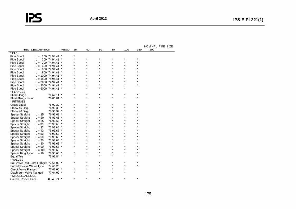
April 2012
IPS-E-PI-221(1)
175
NOMINAL PIPE SIZE ITEM DESCRIPTION MESC 25 40 50 80 100 150 200 * PIPE Pipe Spool L = 100 74.94.41 * * Pipe Spool L = 200 74.94.41 * * * * * * * Pipe Spool L = 300 74.94.41 * * * * * * * Pipe Spool L = 400 74.94.41 * * * * * * * Pipe Spool L = 600 74.94.41 * * * * * * * Pipe Spool L = 800 74.94.41 * * * * * * * Pipe Spool L = 1000 74.94.41 * * * * * * * Pipe Spool L = 1500 74.94.41 * * * * * * * Pipe Spool L = 2000 74.94.41 * * * * * * * Pipe Spool L = 3000 74.94.41 * * * * * * * Pipe Spool L = 6000 74.94.41 * * * * * * * FLANGES Blind Flange 76.62.11 * * * * * * * Blind Flange Liner 76.80.81 * * * * * * * * FITTINGS Cross Equal 76.93.30 * * * * * * * Elbow 45 Deg. 76.93.38 * * * * * * * Elbow 90 Deg. 76.93.39 * * * * * * * Spacer Straight L = 15 76.93.68 * * * * * * * Spacer Straight L = 20 76.93.68 * * * * * * * Spacer Straight L = 25 76.93.68 * * * * * * * Spacer Straight L = 30 76.93.68 * * * * * * * Spacer Straight L = 35 76.93.68 * * * * * * * Spacer Straight L = 40 76.93.68 * * * * * * * Spacer Straight L = 50 76.93.68 * * * * * * * Spacer Straight L = 60 76.93.68 * * * * * * * Spacer Straight L = 70 76.93.68 * * * * * * * Spacer Straight L = 80 76.93.68 * * * * * * * Spacer Straight L = 90 76.93.68 * * * * * * * Spacer Straight L = 100 76.93.68 * * * * * Spacer Ring Type L = 10 76.95.68 * * * * * * * Equal Tee 76.93.84 * * * * * * * * VALVES Ball Valve Red. Bore Flanged 77.55.00 * * * * * * * Butterfly Valve Wafer Type 77.60.20 * * * * * Check Valve Flanged 77.62.00 * * * * * * Diaphragm Valve Flanged 77.64.00 * * * * * * * MISCELLANEOUS Gasket, Raised Face 85.48.74 * * * * * * *
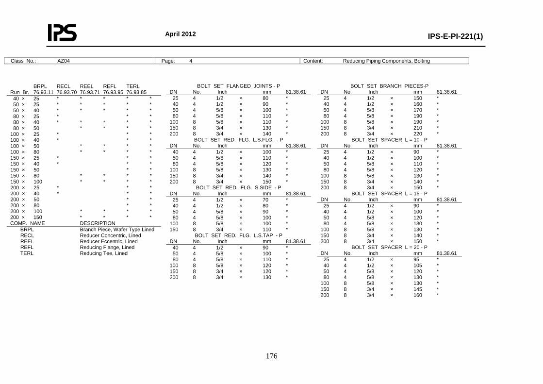
April 2012
IPS-E-PI-221(1)
176
Class No.: AZ04 Page: 4 Content: Reducing Piping Components, Bolting
BRPL RECL REEL REFL TERL Run Br. 76.93.11 76.93.70 76.93.71 76.93.95 76.93.85 40 × 25 * * * * * 50 × 25 * * * * * 50 × 40 * * * * * 80 × 25 * * * 80 × 40 * * * * * 80 × 50 * * * * 100 × 25 * * * 100 × 40 * * * 100 × 50 * * * * 100 × 80 * * * * 150 × 25 * * * 150 × 40 * * * 150 × 50 * * 150 × 80 * * * * 150 × 100 * * * * 200 × 25 * * * 200 × 40 * * * 200 × 50 * * 200 × 80 * * 200 × 100 * * * * 200 × 150 * * * * COMP. NAME DESCRIPTION BRPL Branch Piece, Wafer Type Lined RECL Reducer Concentric, Lined REEL Reducer Eccentric, Lined REFL Reducing Flange, Lined TERL Reducing Tee, Lined
BOLT SET FLANGED JOINTS - P DN No. Inch mm 81.38.61 25 4 1/2 × 80 * 40 4 1/2 × 90 * 50 4 5/8 × 100 * 80 4 5/8 × 110 * 100 8 5/8 × 110 * 150 8 3/4 × 130 * 200 8 3/4 × 140 *
BOLT SET RED. FLG. L.S.FLG. - P DN No. Inch mm 81.38.61 40 4 1/2 × 100 * 50 4 5/8 × 110 * 80 4 5/8 × 120 * 100 8 5/8 × 130 * 150 8 3/4 × 140 * 200 8 3/4 × 150 *
BOLT SET RED. FLG. S.SIDE - P DN No. Inch mm 81.38.61 25 4 1/2 × 70 * 40 4 1/2 × 80 * 50 4 5/8 × 90 * 80 4 5/8 × 100 * 100 8 5/8 × 100 * 150 8 3/4 × 110 *
BOLT SET RED. FLG. L.S.TAP - P DN No. Inch mm 81.38.61 40 4 1/2 × 90 * 50 4 5/8 × 100 * 80 4 5/8 × 110 * 100 8 5/8 × 120 * 150 8 3/4 × 120 * 200 8 3/4 × 130 *
BOLT SET BRANCH PIECES-P DN No. Inch mm 81.38.61 25 4 1/2 × 150 * 40 4 1/2 × 160 * 50 4 5/8 × 170 * 80 4 5/8 × 190 * 100 8 5/8 × 190 * 150 8 3/4 × 210 * 200 8 3/4 × 220 *
BOLT SET SPACER L = 10 - P DN No. Inch mm 81.38.61 25 4 1/2 × 90 * 40 4 1/2 × 100 * 50 4 5/8 × 110 * 80 4 5/8 × 120 * 100 8 5/8 × 130 * 150 8 3/4 × 140 * 200 8 3/4 × 150 *
BOLT SET SPACER L = 15 - P DN No. Inch mm 81.38.61 25 4 1/2 × 90 * 40 4 1/2 × 100 * 50 4 5/8 × 120 * 80 4 5/8 × 130 * 100 8 5/8 × 130 * 150 8 3/4 × 140 * 200 8 3/4 × 150 *
BOLT SET SPACER L = 20 - P DN No. Inch mm 81.38.61 25 4 1/2 × 95 * 40 4 1/2 × 105 * 50 4 5/8 × 120 * 80 4 5/8 × 130 * 100 8 5/8 × 130 * 150 8 3/4 × 145 * 200 8 3/4 × 160 *
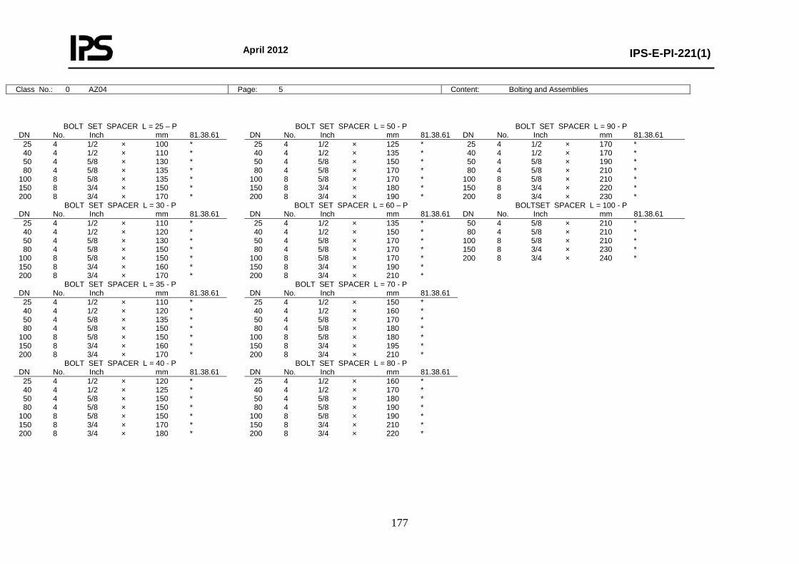
April 2012
IPS-E-PI-221(1)
177
Class No.: 0 AZ04 Page: 5 Content: Bolting and Assemblies
BOLT SET SPACER L = 25 – P DN No. Inch mm 81.38.61 25 4 1/2 × 100 * 40 4 1/2 × 110 * 50 4 5/8 × 130 * 80 4 5/8 × 135 * 100 8 5/8 × 135 * 150 8 3/4 × 150 * 200 8 3/4 × 170 *
BOLT SET SPACER L = 30 - P DN No. Inch mm 81.38.61 25 4 1/2 × 110 * 40 4 1/2 × 120 * 50 4 5/8 × 130 * 80 4 5/8 × 150 * 100 8 5/8 × 150 * 150 8 3/4 × 160 * 200 8 3/4 × 170 *
BOLT SET SPACER L = 35 - P DN No. Inch mm 81.38.61 25 4 1/2 × 110 * 40 4 1/2 × 120 * 50 4 5/8 × 135 * 80 4 5/8 × 150 * 100 8 5/8 × 150 * 150 8 3/4 × 160 * 200 8 3/4 × 170 *
BOLT SET SPACER L = 40 - P DN No. Inch mm 81.38.61 25 4 1/2 × 120 * 40 4 1/2 × 125 * 50 4 5/8 × 150 * 80 4 5/8 × 150 * 100 8 5/8 × 150 * 150 8 3/4 × 170 * 200 8 3/4 × 180 *
BOLT SET SPACER L = 50 - P DN No. Inch mm 81.38.61 25 4 1/2 × 125 * 40 4 1/2 × 135 * 50 4 5/8 × 150 * 80 4 5/8 × 170 * 100 8 5/8 × 170 * 150 8 3/4 × 180 * 200 8 3/4 × 190 *
BOLT SET SPACER L = 60 – P DN No. Inch mm 81.38.61 25 4 1/2 × 135 * 40 4 1/2 × 150 * 50 4 5/8 × 170 * 80 4 5/8 × 170 * 100 8 5/8 × 170 * 150 8 3/4 × 190 * 200 8 3/4 × 210 *
BOLT SET SPACER L = 70 - P DN No. Inch mm 81.38.61 25 4 1/2 × 150 * 40 4 1/2 × 160 * 50 4 5/8 × 170 * 80 4 5/8 × 180 * 100 8 5/8 × 180 * 150 8 3/4 × 195 * 200 8 3/4 × 210 *
BOLT SET SPACER L = 80 - P DN No. Inch mm 81.38.61 25 4 1/2 × 160 * 40 4 1/2 × 170 * 50 4 5/8 × 180 * 80 4 5/8 × 190 * 100 8 5/8 × 190 * 150 8 3/4 × 210 * 200 8 3/4 × 220 *
BOLT SET SPACER L = 90 - P DN No. Inch mm 81.38.61 25 4 1/2 × 170 * 40 4 1/2 × 170 * 50 4 5/8 × 190 * 80 4 5/8 × 210 * 100 8 5/8 × 210 * 150 8 3/4 × 220 * 200 8 3/4 × 230 *
BOLTSET SPACER L = 100 - P DN No. Inch mm 81.38.61 50 4 5/8 × 210 * 80 4 5/8 × 210 * 100 8 5/8 × 210 * 150 8 3/4 × 230 * 200 8 3/4 × 240 *
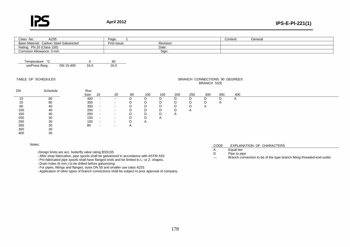
April 2012
IPS-E-PI-221(1)
178
Class No.: AZ05 Page: 1 Content: General Base Material: Carbon Steel Galvanized First Issue: Revision: Rating: PN 20 (Class 150) Date: Corrosion Allowance: 0 mm Sign:
Temperature °C 0 60 urePress Barg. DN 15-400 16.0 16.0
Notes:
-Design limits are acc. butterfly valve rating BS5155 - After shop fabrication, pipe spools shall be galvanized in accordance with ASTM A53 - Pre-fabricated pipe spools shall have flanged ends and be limited to L- or Z- shapes. - Drain holes (6 mm.) to be drilled before galvanizing - For pipes, fittings and flanges, sizes DN 50 and smaller use class AZ01 - Application of other types of branch connections shall be subject to prior approval of company.
TABLE OF SCHEDULES BRANCH CONNECTIONS 90 DEGREES BRANCH SIZE
DN Schedule Run
Size 15 20 80 100 150 200 250 300 350 400 15 20 80
100 150 200 250 300 350 400
80 80 40 40 40 30 30 30 30 30
400 - - D D D D D D D A 350 - - D D D D D D A 300 - - D D D D D A 250 - - D D D D A 200 - - D D D A 150 - - D D A 100 - - D A 80 - - A
CODE EXPLANATION OF CHARACTERS A Equal tee D Pipe to pipe --- Branch connection to be of the type branch fitting threaded-end outlet.
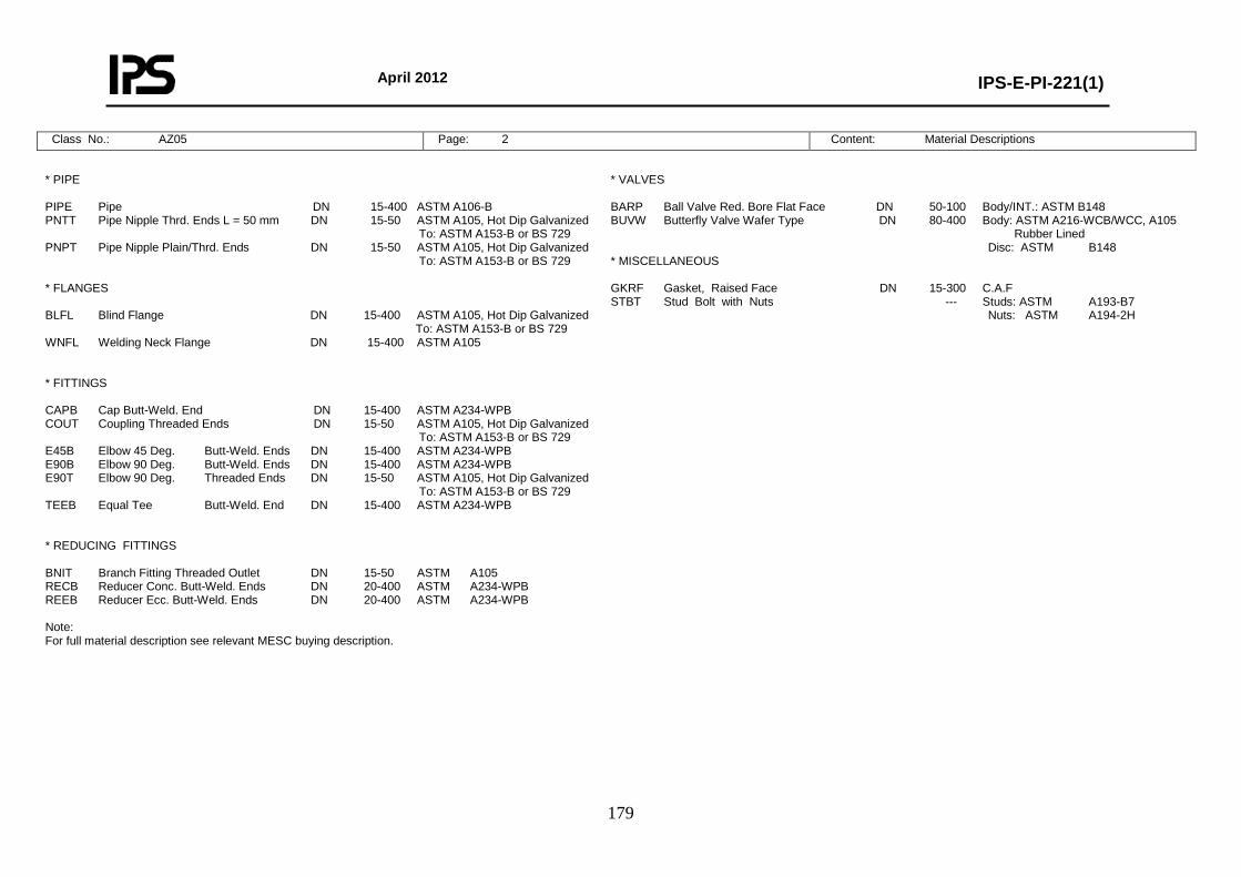
April 2012
IPS-E-PI-221(1)
179
Class No.: AZ05 Page: 2 Content: Material Descriptions
* PIPE PIPE Pipe DN 15-400 ASTM A106-B PNTT Pipe Nipple Thrd. Ends L = 50 mm DN 15-50 ASTM A105, Hot Dip Galvanized To: ASTM A153-B or BS 729 PNPT Pipe Nipple Plain/Thrd. Ends DN 15-50 ASTM A105, Hot Dip Galvanized To: ASTM A153-B or BS 729 * FLANGES BLFL Blind Flange DN 15-400 ASTM A105, Hot Dip Galvanized To: ASTM A153-B or BS 729 WNFL Welding Neck Flange DN 15-400 ASTM A105 * FITTINGS CAPB Cap Butt-Weld. End DN 15-400 ASTM A234-WPB COUT Coupling Threaded Ends DN 15-50 ASTM A105, Hot Dip Galvanized To: ASTM A153-B or BS 729 E45B Elbow 45 Deg. Butt-Weld. Ends DN 15-400 ASTM A234-WPB E90B Elbow 90 Deg. Butt-Weld. Ends DN 15-400 ASTM A234-WPB E90T Elbow 90 Deg. Threaded Ends DN 15-50 ASTM A105, Hot Dip Galvanized To: ASTM A153-B or BS 729 TEEB Equal Tee Butt-Weld. End DN 15-400 ASTM A234-WPB * REDUCING FITTINGS BNIT Branch Fitting Threaded Outlet DN 15-50 ASTM A105 RECB Reducer Conc. Butt-Weld. Ends DN 20-400 ASTM A234-WPB REEB Reducer Ecc. Butt-Weld. Ends DN 20-400 ASTM A234-WPB Note: For full material description see relevant MESC buying description.
* VALVES BARP Ball Valve Red. Bore Flat Face DN 50-100 Body/INT.: ASTM B148 BUVW Butterfly Valve Wafer Type DN 80-400 Body: ASTM A216-WCB/WCC, A105 Rubber Lined Disc: ASTM B148 * MISCELLANEOUS GKRF Gasket, Raised Face DN 15-300 C.A.F STBT Stud Bolt with Nuts --- Studs: ASTM A193-B7 Nuts: ASTM A194-2H
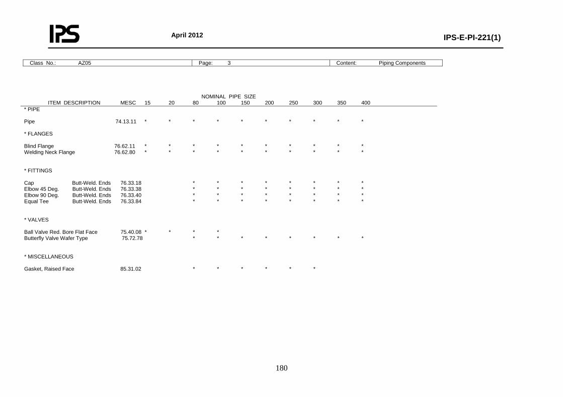
April 2012
IPS-E-PI-221(1)
180
Class No.: AZ05 Page: 3 Content: Piping Components
NOMINAL PIPE SIZE ITEM DESCRIPTION MESC 15 20 80 100 150 200 250 300 350 400 * PIPE Pipe 74.13.11 * * * * * * * * * * * FLANGES Blind Flange 76.62.11 * * * * * * * * * * Welding Neck Flange 76.62.80 * * * * * * * * * * * FITTINGS Cap Butt-Weld. Ends 76.33.18 * * * * * * * * Elbow 45 Deg. Butt-Weld. Ends 76.33.38 * * * * * * * * Elbow 90 Deg. Butt-Weld. Ends 76.33.40 * * * * * * * * Equal Tee Butt-Weld. Ends 76.33.84 * * * * * * * * * VALVES Ball Valve Red. Bore Flat Face 75.40.08 * * * * Butterfly Valve Wafer Type 75.72.78 * * * * * * * * * MISCELLANEOUS Gasket, Raised Face 85.31.02 * * * * * *
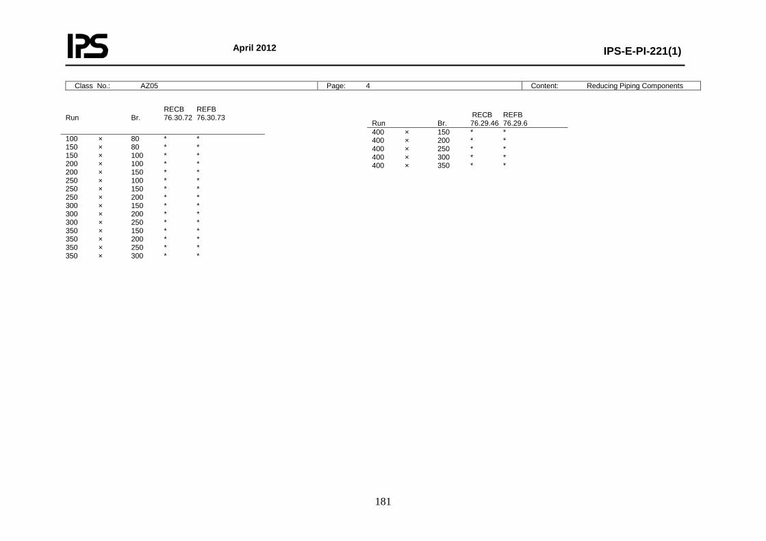
April 2012
IPS-E-PI-221(1)
181
Class No.: AZ05 Page: 4 Content: Reducing Piping Components
RECB REFB Run Br. 76.30.72 76.30.73
100 × 80 * * 150 × 80 * * 150 × 100 * * 200 × 100 * * 200 × 150 * * 250 × 100 * * 250 × 150 * * 250 × 200 * * 300 × 150 * * 300 × 200 * * 300 × 250 * * 350 × 150 * * 350 × 200 * * 350 × 250 * * 350 × 300 * *
RECB REFB Run Br. 76.29.46 76.29.6 400 × 150 * * 400 × 200 * * 400 × 250 * * 400 × 300 * * 400 × 350 * *
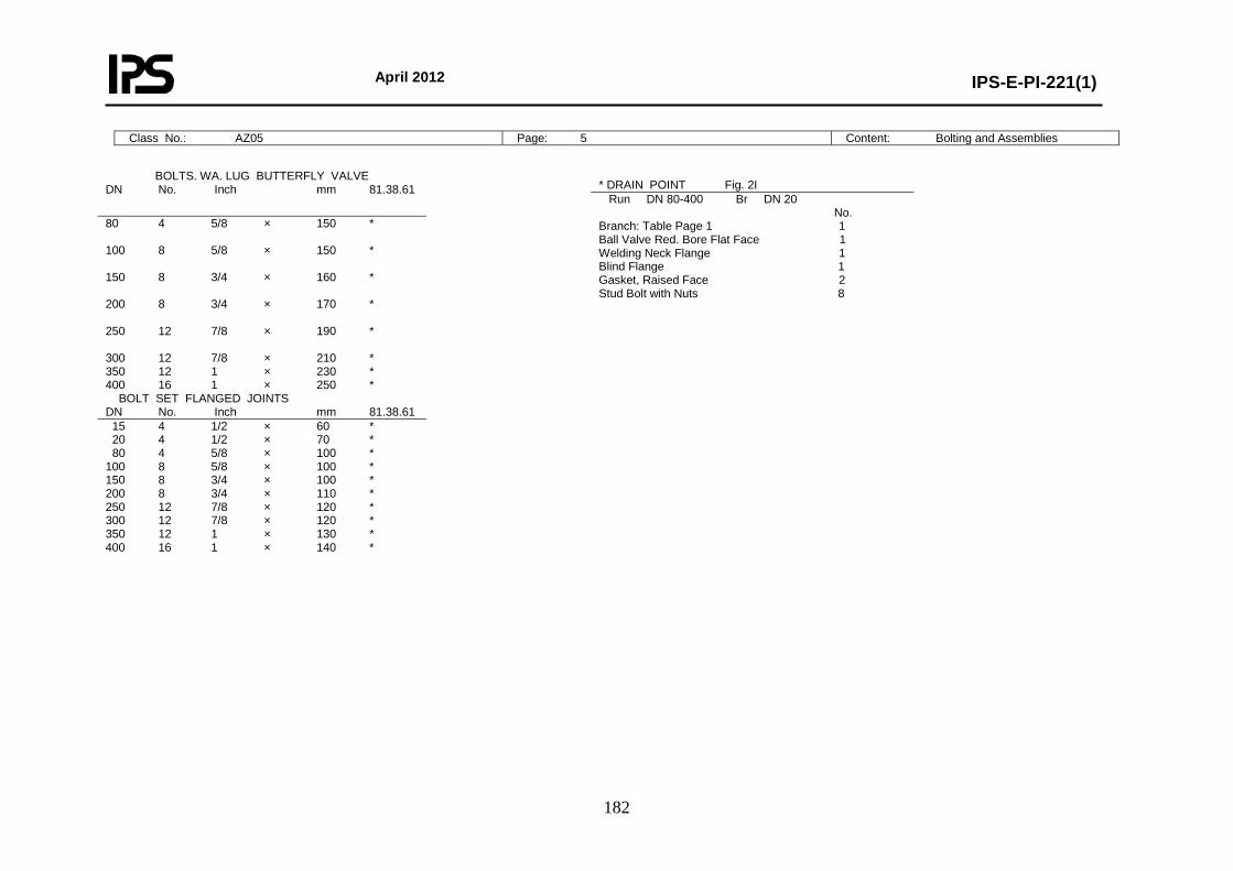
April 2012
IPS-E-PI-221(1)
182
Class No.: AZ05 Page: 5 Content: Bolting and Assemblies
BOLTS. WA. LUG BUTTERFLY VALVE DN No. Inch mm 81.38.61
80 4 5/8 × 150 * 100 8 5/8 × 150 * 150 8 3/4 × 160 * 200 8 3/4 × 170 * 250 12 7/8 × 190 * 300 12 7/8 × 210 * 350 12 1 × 230 * 400 16 1 × 250 * BOLT SET FLANGED JOINTS DN No. Inch mm 81.38.61 15 4 1/2 × 60 * 20 4 1/2 × 70 * 80 4 5/8 × 100 * 100 8 5/8 × 100 * 150 8 3/4 × 100 * 200 8 3/4 × 110 * 250 12 7/8 × 120 * 300 12 7/8 × 120 * 350 12 1 × 130 * 400 16 1 × 140 *
* DRAIN POINT Fig. 2I Run DN 80-400 Br DN 20 No. Branch: Table Page 1 1 Ball Valve Red. Bore Flat Face 1 Welding Neck Flange 1 Blind Flange 1 Gasket, Raised Face 2 Stud Bolt with Nuts 8

April 2012
IPS-E-PI-221(1)
183
Class No.: CN01 Page: 1 Content: General Base Material: Carbon Steel First Issue: Revision: Rating: PN 50 (Class 300) Date: Corrosion Allowance: 1 mm Sign:
Temperature °C 0 50 100 150 200 250 300 350 400 urePress Barg.
DN 15-600 50.5 50.0 46.3 45.1 43.8 41.8 38.8 36.8 32.6
Notes:
-Design limits are acc. flange rating ANSI B16.5 Material Group 1.1 - Piston type check valves for horizontal mounting only. - Application of other types of branch connections is subject to company approval
TABLE OF SCHEDULES BRANCH CONNECTIONS 90 DEGREES BRANCH SIZE
DN Schedule Run
Size 15 20 25 40 50 80 100 150 200 250 300 350 400 450 500 600 15 20 25 40 50 80
100 150 200 250 300 350 400 450 500 600
80 80 80 80 40 40 40 40 30 30 30 30 30 30 30 30
600 C C C C E E E E E E E E E E E A 500 C C C C E E E E E E E E E E A 450 C C C C E E E E E E E E E A 400 C C C C E E E E E E E E A 350 C C C C E E E E E E E A 300 C C C C E E E E E E A 250 C C C C E E E E E A 200 C C C C E E E E A 150 C C C C E E E A 100 C C C C D D A 80 C C C C D A 50 C C C B A 40 C B B A 25 B B A 20 B A 15 A
CODE EXPLANATION OF CHARACTERS A Equal tee B Reducing tee C Branch socket weld-end D Pipe to pipe E Branch outlet reducing butt-weld
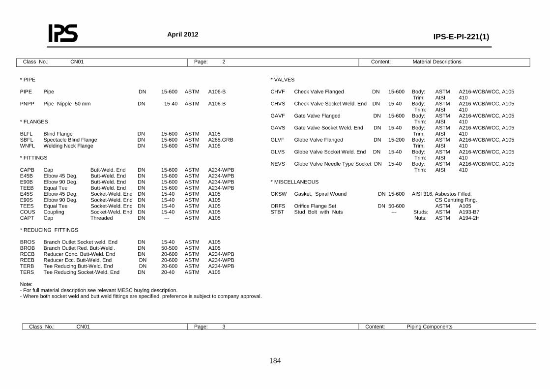
April 2012
IPS-E-PI-221(1)
184
Class No.: CN01 Page: 2 Content: Material Descriptions
* PIPE PIPE Pipe DN 15-600 ASTM A106-B PNPP Pipe Nipple 50 mm DN 15-40 ASTM A106-B * FLANGES BLFL Blind Flange DN 15-600 ASTM A105 SBFL Spectacle Blind Flange DN 15-600 ASTM A285.GRB WNFL Welding Neck Flange DN 15-600 ASTM A105 * FITTINGS CAPB Cap Butt-Weld. End DN 15-600 ASTM A234-WPB E45B Elbow 45 Deg. Butt-Weld. End DN 15-600 ASTM A234-WPB E90B Elbow 90 Deg. Butt-Weld. End DN 15-600 ASTM A234-WPB TEEB Equal Tee Butt-Weld. End DN 15-600 ASTM A234-WPB E45S Elbow 45 Deg. Socket-Weld. End DN 15-40 ASTM A105 E90S Elbow 90 Deg. Socket-Weld. End DN 15-40 ASTM A105 TEES Equal Tee Socket-Weld. End DN 15-40 ASTM A105 COUS Coupling Socket-Weld. End DN 15-40 ASTM A105 CAPT Cap Threaded DN --- ASTM A105 * REDUCING FITTINGS BROS Branch Outlet Socket weld. End DN 15-40 ASTM A105 BROB Branch Outlet Red. Butt-Weld . DN 50-500 ASTM A105 RECB Reducer Conc. Butt-Weld. End DN 20-600 ASTM A234-WPB REEB Reducer Ecc. Butt-Weld. End DN 20-600 ASTM A234-WPB TERB Tee Reducing Butt-Weld. End DN 20-600 ASTM A234-WPB TERS Tee Reducing Socket-Weld. End DN 20-40 ASTM A105 Note: - For full material description see relevant MESC buying description. - Where both socket weld and butt weld fittings are specified, preference is subject to company approval.
* VALVES CHVF Check Valve Flanged DN 15-600 Body: ASTM A216-WCB/WCC, A105 Trim: AISI 410 CHVS Check Valve Socket Weld. End DN 15-40 Body: ASTM A216-WCB/WCC, A105 Trim: AISI 410 GAVF Gate Valve Flanged DN 15-600 Body: ASTM A216-WCB/WCC, A105 Trim: AISI 410 GAVS Gate Valve Socket Weld. End DN 15-40 Body: ASTM A216-WCB/WCC, A105 Trim: AISI 410 GLVF Globe Valve Flanged DN 15-200 Body: ASTM A216-WCB/WCC, A105 Trim: AISI 410 GLVS Globe Valve Socket Weld. End DN 15-40 Body: ASTM A216-WCB/WCC, A105 Trim: AISI 410 NEVS Globe Valve Needle Type Socket DN 15-40 Body: ASTM A216-WCB/WCC, A105 Trim: AISI 410 * MISCELLANEOUS GKSW Gasket, Spiral Wound DN 15-600 AISI 316, Asbestos Filled, CS Centring Ring. ORFS Orifice Flange Set DN 50-600 ASTM A105 STBT Stud Bolt with Nuts --- Studs: ASTM A193-B7 Nuts: ASTM A194-2H
Class No.: CN01 Page: 3 Content: Piping Components
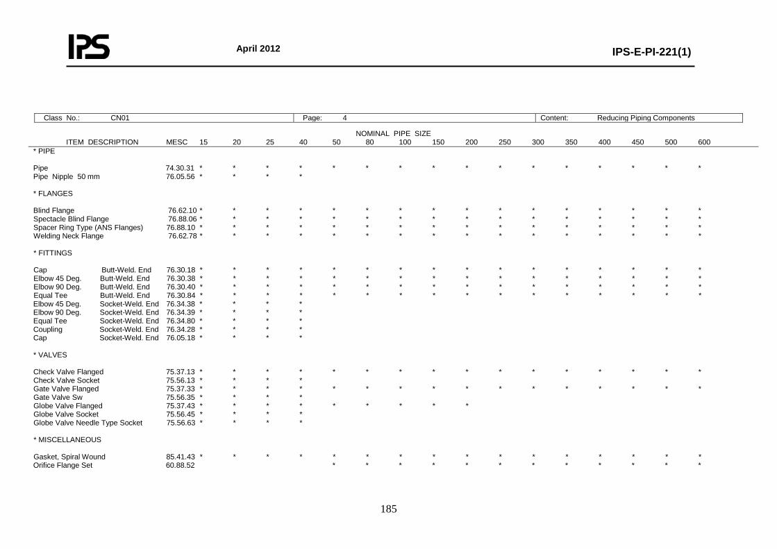
April 2012
IPS-E-PI-221(1)
185
Class No.: CN01 Page: 4 Content: Reducing Piping Components
NOMINAL PIPE SIZE ITEM DESCRIPTION MESC 15 20 25 40 50 80 100 150 200 250 300 350 400 450 500 600 * PIPE Pipe 74.30.31 * * * * * * * * * * * * * * * * Pipe Nipple 50 mm 76.05.56 * * * * * FLANGES Blind Flange 76.62.10 * * * * * * * * * * * * * * * * Spectacle Blind Flange 76.88.06 * * * * * * * * * * * * * * * * Spacer Ring Type (ANS Flanges) 76.88.10 * * * * * * * * * * * * * * * * Welding Neck Flange 76.62.78 * * * * * * * * * * * * * * * * * FITTINGS Cap Butt-Weld. End 76.30.18 * * * * * * * * * * * * * * * * Elbow 45 Deg. Butt-Weld. End 76.30.38 * * * * * * * * * * * * * * * * Elbow 90 Deg. Butt-Weld. End 76.30.40 * * * * * * * * * * * * * * * * Equal Tee Butt-Weld. End 76.30.84 * * * * * * * * * * * * * * * * Elbow 45 Deg. Socket-Weld. End 76.34.38 * * * * Elbow 90 Deg. Socket-Weld. End 76.34.39 * * * * Equal Tee Socket-Weld. End 76.34.80 * * * * Coupling Socket-Weld. End 76.34.28 * * * * Cap Socket-Weld. End 76.05.18 * * * * * VALVES Check Valve Flanged 75.37.13 * * * * * * * * * * * * * * * * Check Valve Socket 75.56.13 * * * * Gate Valve Flanged 75.37.33 * * * * * * * * * * * * * * * * Gate Valve Sw 75.56.35 * * * * Globe Valve Flanged 75.37.43 * * * * * * * * * Globe Valve Socket 75.56.45 * * * * Globe Valve Needle Type Socket 75.56.63 * * * * * MISCELLANEOUS Gasket, Spiral Wound 85.41.43 * * * * * * * * * * * * * * * * Orifice Flange Set 60.88.52 * * * * * * * * * * * *
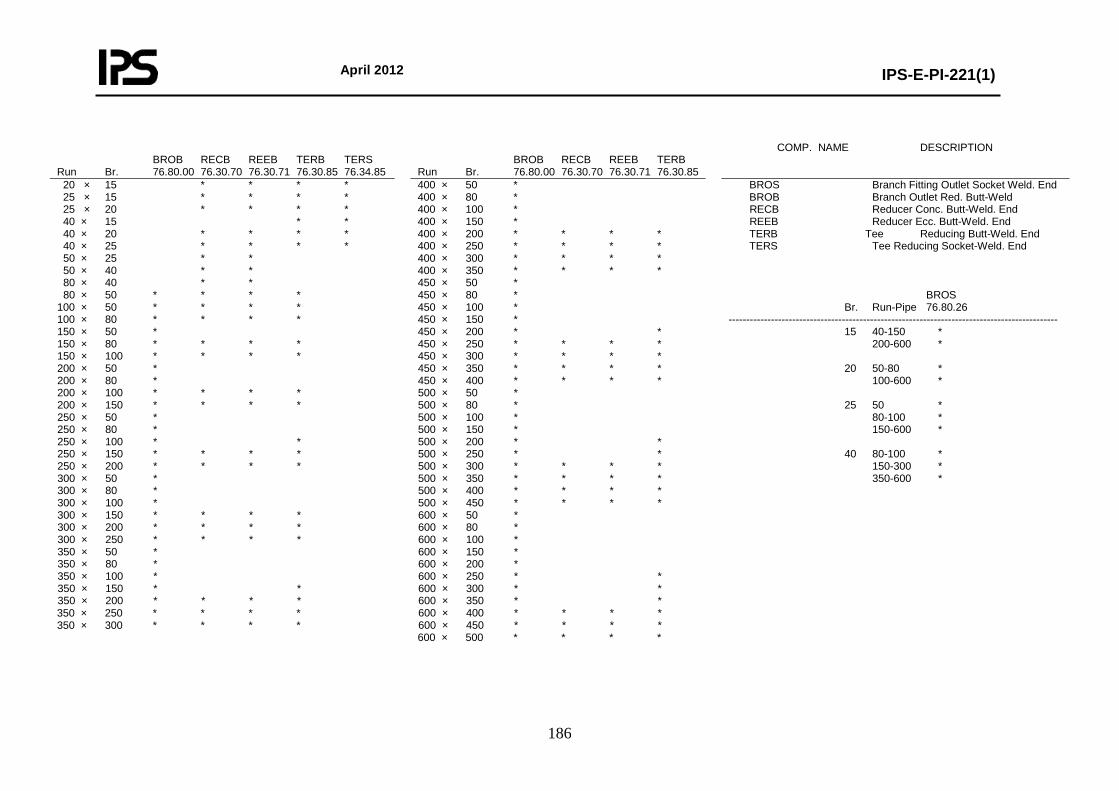
April 2012
IPS-E-PI-221(1)
186
BROB RECB REEB TERB TERS Run Br. 76.80.00 76.30.70 76.30.71 76.30.85 76.34.85
BROB RECB REEB TERB Run Br. 76.80.00 76.30.70 76.30.71 76.30.85
COMP. NAME DESCRIPTION
20 × 15 * * * * 25 × 15 * * * * 25 × 20 * * * * 40 × 15 * * 40 × 20 * * * * 40 × 25 * * * * 50 × 25 * * 50 × 40 * * 80 × 40 * * 80 × 50 * * * * 100 × 50 * * * * 100 × 80 * * * * 150 × 50 * 150 × 80 * * * * 150 × 100 * * * * 200 × 50 * 200 × 80 * 200 × 100 * * * * 200 × 150 * * * * 250 × 50 * 250 × 80 * 250 × 100 * * 250 × 150 * * * * 250 × 200 * * * * 300 × 50 * 300 × 80 * 300 × 100 * 300 × 150 * * * * 300 × 200 * * * * 300 × 250 * * * * 350 × 50 * 350 × 80 * 350 × 100 * 350 × 150 * * 350 × 200 * * * * 350 × 250 * * * * 350 × 300 * * * *
400 × 50 * 400 × 80 * 400 × 100 * 400 × 150 * 400 × 200 * * * * 400 × 250 * * * * 400 × 300 * * * * 400 × 350 * * * * 450 × 50 * 450 × 80 * 450 × 100 * 450 × 150 * 450 × 200 * * 450 × 250 * * * * 450 × 300 * * * * 450 × 350 * * * * 450 × 400 * * * * 500 × 50 * 500 × 80 * 500 × 100 * 500 × 150 * 500 × 200 * * 500 × 250 * * 500 × 300 * * * * 500 × 350 * * * * 500 × 400 * * * * 500 × 450 * * * * 600 × 50 * 600 × 80 * 600 × 100 * 600 × 150 * 600 × 200 * 600 × 250 * * 600 × 300 * * 600 × 350 * * 600 × 400 * * * * 600 × 450 * * * * 600 × 500 * * * *
BROS Branch Fitting Outlet Socket Weld. End BROB Branch Outlet Red. Butt-Weld RECB Reducer Conc. Butt-Weld. End REEB Reducer Ecc. Butt-Weld. End TERB Tee Reducing Butt-Weld. End TERS Tee Reducing Socket-Weld. End BROS Br. Run-Pipe 76.80.26 --------------------------------------------------------------------------------------------- 15 40-150 * 200-600 * 20 50-80 * 100-600 * 25 50 * 80-100 * 150-600 * 40 80-100 * 150-300 * 350-600 *
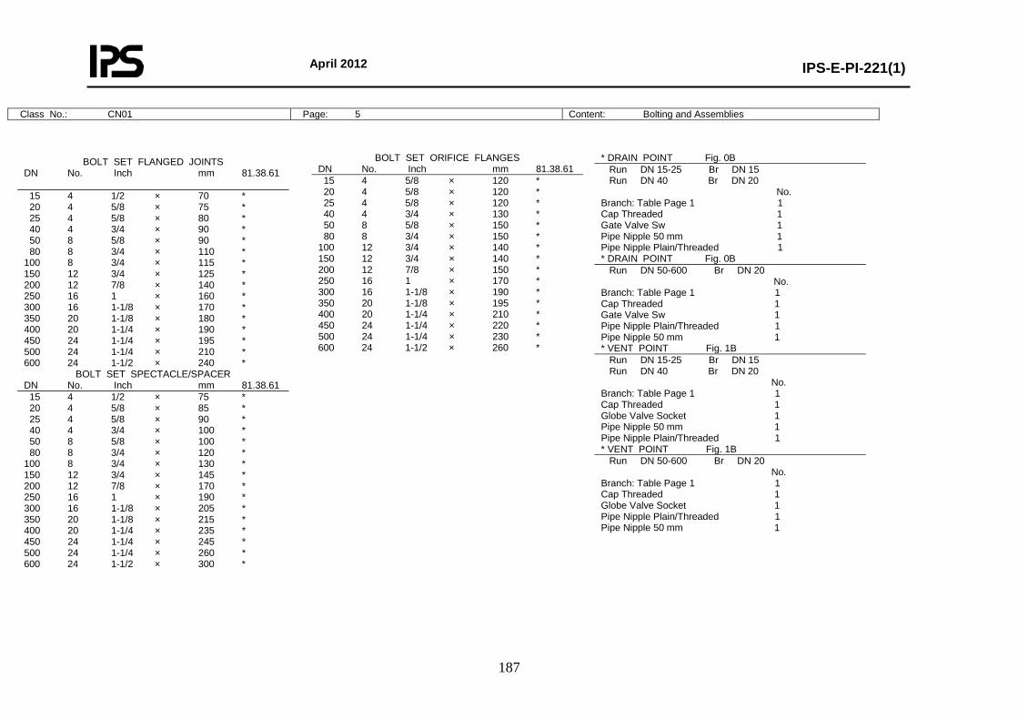
April 2012
IPS-E-PI-221(1)
187
Class No.: CN01 Page: 5 Content: Bolting and Assemblies
BOLT SET FLANGED JOINTS DN No. Inch mm 81.38.61 15 4 1/2 × 70 * 20 4 5/8 × 75 * 25 4 5/8 × 80 * 40 4 3/4 × 90 * 50 8 5/8 × 90 * 80 8 3/4 × 110 * 100 8 3/4 × 115 * 150 12 3/4 × 125 * 200 12 7/8 × 140 * 250 16 1 × 160 * 300 16 1-1/8 × 170 * 350 20 1-1/8 × 180 * 400 20 1-1/4 × 190 * 450 24 1-1/4 × 195 * 500 24 1-1/4 × 210 * 600 24 1-1/2 × 240 *
BOLT SET SPECTACLE/SPACER DN No. Inch mm 81.38.61 15 4 1/2 × 75 * 20 4 5/8 × 85 * 25 4 5/8 × 90 * 40 4 3/4 × 100 * 50 8 5/8 × 100 * 80 8 3/4 × 120 * 100 8 3/4 × 130 * 150 12 3/4 × 145 * 200 12 7/8 × 170 * 250 16 1 × 190 * 300 16 1-1/8 × 205 * 350 20 1-1/8 × 215 * 400 20 1-1/4 × 235 * 450 24 1-1/4 × 245 * 500 24 1-1/4 × 260 * 600 24 1-1/2 × 300 *
BOLT SET ORIFICE FLANGES DN No. Inch mm 81.38.61 15 4 5/8 × 120 * 20 4 5/8 × 120 * 25 4 5/8 × 120 * 40 4 3/4 × 130 * 50 8 5/8 × 150 * 80 8 3/4 × 150 * 100 12 3/4 × 140 * 150 12 3/4 × 140 * 200 12 7/8 × 150 * 250 16 1 × 170 * 300 16 1-1/8 × 190 * 350 20 1-1/8 × 195 * 400 20 1-1/4 × 210 * 450 24 1-1/4 × 220 * 500 24 1-1/4 × 230 * 600 24 1-1/2 × 260 *
* DRAIN POINT Fig. 0B Run DN 15-25 Br DN 15 Run DN 40 Br DN 20 No. Branch: Table Page 1 1 Cap Threaded 1 Gate Valve Sw 1 Pipe Nipple 50 mm 1 Pipe Nipple Plain/Threaded 1 * DRAIN POINT Fig. 0B Run DN 50-600 Br DN 20 No. Branch: Table Page 1 1 Cap Threaded 1 Gate Valve Sw 1 Pipe Nipple Plain/Threaded 1 Pipe Nipple 50 mm 1 * VENT POINT Fig. 1B Run DN 15-25 Br DN 15 Run DN 40 Br DN 20 No. Branch: Table Page 1 1 Cap Threaded 1 Globe Valve Socket 1 Pipe Nipple 50 mm 1 Pipe Nipple Plain/Threaded 1 * VENT POINT Fig. 1B Run DN 50-600 Br DN 20 No. Branch: Table Page 1 1 Cap Threaded 1 Globe Valve Socket 1 Pipe Nipple Plain/Threaded 1 Pipe Nipple 50 mm 1
April 2012
IPS-E-PI-221(1)
188
Class No.: CN02 Page: 1 Content: General Base Material: Carbon Steel First Issue: Revision: Rating: PN 50 (Class 300) Date: Corrosion Allowance: 1 mm Sign:
Temperature °C 0 50 75 100 125 150 175 200 urePress Barg.
DN 15-80 DN 100-150
DN 200-600
50.0 42.0
31.0
49.0 42.0
31.0
48.0 42.0
31.0
46.4 39.0
29.0
38.0 32.0
23.0
29.0 24.0
18.0
20.0 17.0
12.0
11.0 9.0
7.0
Notes:
-Design limits are acc. flange rating ANSI B16.5 Material Group 1.1 and ball valve rating acc. BS 5351 - Piston type check valves for horizontal mounting only. - Application of other types of branch connections is subject to company approval
TABLE OF SCHEDULES BRANCH CONNECTIONS 90 DEGREES BRANCH SIZE
DN Schedule Run Size 15 20 25 40 50 80 100 150 200 250 300 350 400 450 500 600
15 20 25 40 50 80
100 150 200 250 300 350 400 450 500 600
80 80 80 80 40 40 40 40 30 30 30 30 30 30 30 30
600 C C C C E E E E E E E E E E E A 500 C C C C E E E E E E E E E E A 450 C C C C E E E E E E E E E A 400 C C C C E E E E E E E E A 350 C C C C E E E E E E E A 300 C C C C E E E E E E A 250 C C C C E E E E E A 200 C C C C E E E E A 150 C C C C E E E A 100 C C C C D D A 80 C C C C D A 50 C C C B A 40 C B B A 25 B B A 20 B A 15 A
CODE EXPLANATION OF CHARACTERS A Equal tee B Reducing tee C Branch fitting outlet socket weld end D Pipe to pipe E Branch outlet reducing butt-weld
April 2012
IPS-E-PI-221(1)
189
Class No.: CN02 Page: 2 Content: Material Descriptions
* PIPE PIPE Pipe DN 15-400 API 5L-B (Seamless) DN 450-600 API 5L-B (Welded) PNPP Pipe Nipple 50 mm DN 15-40 ASTM 5L-B (Seamless) * FLANGES BLFL Blind Flange DN 15-600 ASTM A105 SBFL Spectacle Blind Flange DN 15-600 ASTM A285 GRB SOFL Slip-On Flange DN 15-600 ASTM A105 WNFL Welding Neck Flange DN 15-600 ASTM A105 * FITTINGS CAPB Cap Butt-Weld. End DN 15-600 ASTM A234-WPB E45B Elbow 45 Deg. Butt-Weld. End DN 15-600 ASTM A234-WPB E90B Elbow 90 Deg. Butt-Weld. End DN 15-600 ASTM A234-WPB TEEB Equal Tee Butt-Weld. End DN 15-600 ASTM A234-WPB E45S Elbow 45 Deg. Socket-Weld. End DN 15-40 ASTM A105 E90S Elbow 90 Deg. Socket-Weld. End DN 15-40 ASTM A105 TEES Equal Tee Socket-Weld. End DN 15-40 ASTM A105 COUS Coupling Socket-Weld. End DN 15-40 ASTM A105 CAPS Cap Socket-Weld. End DN 15-40 ASTM A105 * REDUCING FITTINGS BROS Branch Outlet Socket Weld. End DN 15-40 ASTM A105 BROB Branch Outlet Red. Butt-Weld . DN 50-600 ASTM A105 RECB Reducer Conc. Butt-Weld. End DN 20-600 ASTM A234-WPB REEB Reducer Ecc. Butt-Weld. End DN 20-600 ASTM A234-WPB TERB Tee Reducing Butt-Weld. End DN 20-600 ASTM A234-WPB TERS Tee Reducing Socket-Weld. End DN 20-40 ASTM A105 Note: - For full material description see relevant MESC buying description. - Where both socket weld and butt weld fittings are specified, preference is subject to company approval.
* VALVES BARF Ball Valve Red. Bore Flanged DN 15-250 Body: ASTM A216-WCB/WCC, A105 Ball/Stem: AISI 316, 316L Seats: PTFE CHVF Check Valve Flanged DN 15-600 Body: ASTM A216-WCB/WCC, A105 Trim: AISI 410 CHVS Check Valve Socket DN 15-40 Body: ASTM A216-WCB/WCC, A105 Trim: AISI 410 GAVF Gate Valve Flanged DN 15-600 Body: ASTM A216-WCB/WCC, A105 Trim: AISI 410 GLVF Globe Valve Flanged DN 15-200 Body: ASTM A216-WCB/WCC, A105 Trim: AISI 410 GLVS Globe Valve Socket DN 15-40 Body: ASTM A216-WCB/WCC, A105 Trim: AISI 410 NEVS Globe Valve Needle Type Socket DN 15-40 Body: ASTM A216-WCB/WCC, A105 Trim: AISI 410 * MISCELLANEOUS GKRF Gasket, Raised Face DN 15-600 CAF, Oil Resistant ORFS Orifice Flange Set DN 50-600 ASTM A105 STBT Stud Bolt with Nuts --- Studs: ASTM A193-B7 Nuts: ASTM A194-2H
Class No.: CN02 Page: 3 Content: Piping Components
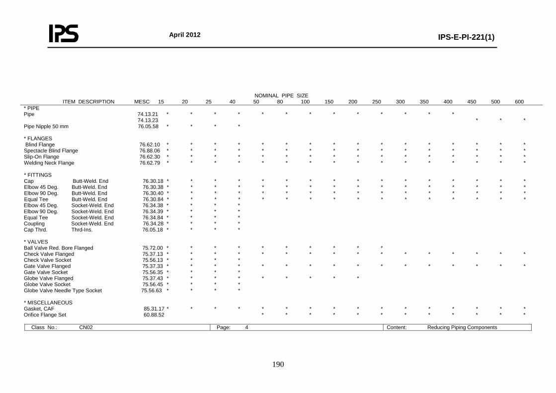
April 2012
IPS-E-PI-221(1)
190
Class No.: CN02 Page: 4 Content: Reducing Piping Components
NOMINAL PIPE SIZE ITEM DESCRIPTION MESC 15 20 25 40 50 80 100 150 200 250 300 350 400 450 500 600
* PIPE Pipe 74.13.21 * * * * * * * * * * * * * 74.13.23 * * * Pipe Nipple 50 mm 76.05.58 * * * * * FLANGES Blind Flange 76.62.10 * * * * * * * * * * * * * * * * Spectacle Blind Flange 76.88.06 * * * * * * * * * * * * * * * * Slip-On Flange 76.62.30 * * * * * * * * * * * * * * * * Welding Neck Flange 76.62.79 * * * * * * * * * * * * * * * * * FITTINGS Cap Butt-Weld. End 76.30.18 * * * * * * * * * * * * * * * * Elbow 45 Deg. Butt-Weld. End 76.30.38 * * * * * * * * * * * * * * * * Elbow 90 Deg. Butt-Weld. End 76.30.40 * * * * * * * * * * * * * * * * Equal Tee Butt-Weld. End 76.30.84 * * * * * * * * * * * * * * * * Elbow 45 Deg. Socket-Weld. End 76.34.38 * * * * Elbow 90 Deg. Socket-Weld. End 76.34.39 * * * * Equal Tee Socket-Weld. End 76.34.84 * * * * Coupling Socket-Weld. End 76.34.28 * * * * Cap Thrd. Thrd-Ins. 76.05.18 * * * * * VALVES Ball Valve Red. Bore Flanged 75.72.00 * * * * * * * * * * Check Valve Flanged 75.37.13 * * * * * * * * * * * * * * * * Check Valve Socket 75.56.13 * * * * Gate Valve Flanged 75.37.33 * * * * * * * * * * * * * * * * Gate Valve Socket 75.56.35 * * * * Globe Valve Flanged 75.37.43 * * * * * * * * * Globe Valve Socket 75.56.45 * * * * Globe Valve Needle Type Socket 75.56.63 * * * * * MISCELLANEOUS Gasket, CAF 85.31.17 * * * * * * * * * * * * * * * * Orifice Flange Set 60.88.52 * * * * * * * * * * * *
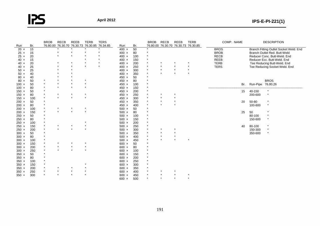
April 2012
IPS-E-PI-221(1)
191
BROB RECB REEB TERB TERS Run Br. 76.80.00 76.30.70 76.30.73 76.30.85 76.34.85
BROB RECB REEB TERB Run Br. 76.80.00 76.30.70 76.30.73 76.30.85
COMP. NAME DESCRIPTION
20 × 15 * * * * 25 × 15 * * * * 25 × 20 * * * * 40 × 15 * * 40 × 20 * * * * 40 × 25 * * * * 50 × 25 * * 50 × 40 * * 80 × 40 * * 80 × 50 * * * * 100 × 50 * * * * 100 × 80 * * * * 150 × 50 * 150 × 80 * * * * 150 × 100 * * * * 200 × 50 * 200 × 80 * 200 × 100 * * * * 200 × 150 * * * * 250 × 50 * 250 × 80 * 250 × 100 * * 250 × 150 * * * * 250 × 200 * * * * 300 × 50 * 300 × 80 * 300 × 100 * 300 × 150 * * * * 300 × 200 * * * * 300 × 250 * * * * 350 × 50 * 350 × 80 * 350 × 100 * 350 × 150 * * 350 × 200 * * * * 350 × 250 * * * * 350 × 300 * * * *
400 × 50 * 400 × 80 * 400 × 100 * 400 × 150 * 400 × 200 * * * * 400 × 250 * * * * 400 × 300 * * * * 400 × 350 * * * * 450 × 50 * 450 × 80 * 450 × 100 * 450 × 150 * 450 × 200 * 450 × 250 * * * 450 × 300 * * * 450 × 350 * * * 450 × 400 * * * 500 × 50 * 500 × 80 * 500 × 100 * 500 × 150 * 500 × 200 * 500 × 250 * 500 × 300 * * * 500 × 350 * * * 500 × 400 * * * 500 × 450 * * * * 600 × 50 * 600 × 80 * 600 × 100 * 600 × 150 * 600 × 200 * 600 × 250 * 600 × 300 * 600 × 350 * 600 × 400 * * * 600 × 450 * * * * 600 × 500 * * * *
BROS Branch Fitting Outlet Socket Weld. End BROB Branch Outlet Red. Butt-Weld RECB Reducer Conc. Butt-Weld. End REEB Reducer Ecc. Butt-Weld. End TERB Tee Reducing Butt-Weld. End TERS Tee Reducing Socket-Weld. End BROS Br. Run-Pipe 76.80.26 --------------------------------------------------------------------------------------------- 15 40-150 * 200-600 * 20 50-80 * 100-600 * 25 50 * 80-100 * 150-600 * 40 80-100 * 150-300 * 350-600 *

April 2012
IPS-E-PI-221(1)
192
Class No.: CN02 Page: 5 Content: Bolting and Assemblies
BOLT SET FLANGED JOINTS DN No. Inch mm 81.38.61 15 4 1/2 × 70 * 20 4 5/8 × 75 * 25 4 5/8 × 80 * 40 4 3/4 × 90 * 50 8 5/8 × 90 * 80 8 3/4 × 110 * 100 8 3/4 × 115 * 150 12 3/4 × 125 * 200 12 7/8 × 140 * 250 16 1 × 160 * 300 16 1-1/8 × 170 * 350 20 1-1/8 × 180 * 400 20 1-1/4 × 190 * 450 24 1-1/4 × 195 * 500 24 1-1/4 × 210 * 600 24 1-1/2 × 235 *
BOLT SET SPECTACLE/SPACER DN No. Inch mm 81.38.61 15 4 1/2 × 75 * 20 4 5/8 × 85 * 25 4 5/8 × 90 * 40 4 3/4 × 100 * 50 8 5/8 × 100 * 80 8 3/4 × 120 * 100 8 3/4 × 130 * 150 12 3/4 × 145 * 200 12 7/8 × 170 * 250 16 1 × 190 * 300 16 1-1/8 × 205 * 350 20 1-1/8 × 215 * 400 20 1-1/4 × 235 * 450 24 1-1/4 × 245 * 500 24 1-1/4 × 260 * 600 24 1-1/2 × 295 *
BOLT SET ORIFICE FLANGES DN No. Inch mm 81.38.61 15 4 5/8 × 120 * 20 4 5/8 × 120 * 25 4 5/8 × 120 * 40 4 3/4 × 130 * 50 8 5/8 × 150 * 80 8 3/4 × 150 * 100 12 3/4 × 140 * 150 12 3/4 × 140 * 200 12 7/8 × 150 * 250 16 1 × 170 * 300 16 1-1/8 × 190 * 350 20 1-1/8 × 195 * 400 20 1-1/4 × 210 * 450 24 1-1/4 × 220 * 500 24 1-1/4 × 230 * 600 24 1-1/2 × 260 *
* DRAIN POINT Fig. 2I Run DN 15-25 Br DN 15 Run DN 40 Br DN 20 No. Branch: Table Page 1 1 Ball Valve Red. Bore Flanged 1 Blind Flange 1 Gasket Raised Face 2 Stud Bolt with Nuts 8 Welding Neck Flange 1 * DRAIN POINT Fig. 2J Run DN 50-600 Br DN 20 No. Branch: Table Page 1 1 Ball Valve Red. Bore Flanged 1 Blind Flange 1 Gasket Raised Face 2 Pipe Nipple 50 mm 1 Stud Bolt with Nuts 8 Welding Neck Flange 1 * VENT POINT Fig. 1I Run DN 15-25 Br DN 15 Run DN 40 Br DN 20 No. Branch: Table Page 1 1 Blind Flange 1 Gasket Raised Face 2 Globe Valve Flanged 1 Stud Bolt with Nuts 8 Welding Neck Flange 1 * VENT POINT Fig. 1 J Run DN 50-600 Br DN 20 No. Branch: Table Page 1 1 Blind Flange 1 Gasket Raised Face 2 Globe Valve Flanged 1 Pipe Nipple 50 mm 1 Stud Bolt with Nuts 8 Welding Neck Flange 1
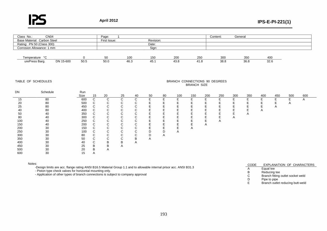
April 2012
IPS-E-PI-221(1)
193
Class No.: CN04 Page: 1 Content: General Base Material: Carbon Steel First Issue: Revision: Rating: PN 50 (Class 300) Date: Corrosion Allowance: 1 mm Sign:
Temperature °C 0 50 100 150 200 250 300 350 400 urePress Barg.
DN 15-600 50.5 50.0 46.3 45.1 43.8 41.8 38.8 36.8 32.6
Notes:
-Design limits are acc. flange rating ANSI B16.5 Material Group 1.1 and to allowable internal prisor acc. ANSI B31.3 - Piston type check valves for horizontal mounting only. - Application of other types of branch connections is subject to company approval
TABLE OF SCHEDULES BRANCH CONNECTIONS 90 DEGREES BRANCH SIZE
DN Schedule Run
Size 15 20 25 40 50 80 100 150 200 250 300 350 400 450 500 600 15 20 25 40 50 80
100 150 200 250 300 350 400 450 500 600
80 80 80 80 40 40 40 40 30 30 30 30 30 30 30 30
600 C C C C E E E E E E E E E E E A 500 C C C C E E E E E E E E E E A 450 C C C C E E E E E E E E E A 400 C C C C E E E E E E E E A 350 C C C C E E E E E E E A 300 C C C C E E E E E E A 250 C C C C E E E E E A 200 C C C C E E E E A 150 C C C C E E E A 100 C C C C D D A 80 C C C C D A 50 C C C B A 40 C B B A 25 B B A 20 B A 15 A
CODE EXPLANATION OF CHARACTERS A Equal tee B Reducing tee C Branch fitting outlet socket weld D Pipe to pipe E Branch outlet reducing butt-weld

April 2012
IPS-E-PI-221(1)
194
Class No.: CN04 Page: 2 Content: Material Descriptions
* PIPE PIPE Pipe DN 15-600 ASTM A106-B PNPP Pipe Nipple 50 mm DN 15-40 ASTM A106-B * FLANGES BLFL Blind Flange DN 15-600 ASTM A105 SBFL Spectacle Blind Flange DN 15-600 ASTM A516-60 SPRT Spacer Ring Type (ANS Flanges) DN 15-600 ASTM A516-60 WNFL Welding Neck Flange DN 15-600 ASTM A105 * FITTINGS CAPB Cap Butt-Weld. End DN 15-600 ASTM A234-WPB E45B Elbow 45 Deg. Butt-Weld. End DN 15-600 ASTM A234-WPB E90B Elbow 90 Deg. Butt-Weld. End DN 15-600 ASTM A234-WPB TEEB Equal Tee Butt-Weld. End DN 15-600 ASTM A234-WPB E45S Elbow 45 Deg. Socket-Weld. End DN 15-40 ASTM A105 E90S Elbow 90 Deg. Socket-Weld. End DN 15-40 ASTM A105 TEES Equal Tee Socket-Weld. End DN 15-40 ASTM A105 COUS Coupling Socket-Weld. End DN 15-40 ASTM A105 CAPS Cap Socket-Weld. End DN 15-40 ASTM A105 * REDUCING FITTINGS BROS Branch Fitting Outlet Socket-Weld. End DN 15-40 ASTM A105 BROB Branch Outlet Red. Butt-Weld. DN 50-600 ASTM A105 RECB Reducer Conc. Butt-Weld. End DN 20-600 ASTM A234-WPB REEB Reducer Ecc. Butt-Weld. End DN 20-600 ASTM A234-WPB TERB Tee Reducing Butt-Weld. End DN 20-600 ASTM A234-WPB TERS Tee Reducing Socket-Weld. End DN 20-40 ASTM A105 Note: - For full material description see relevant MESC buying description. - Where both socket weld and butt weld fittings are specified, preference is subject to company approval.
* VALVES CHVF Check Valve Flanged DN 15-600 Body: ASTM A216-WCB/WCC, A105 Trim: AISI 316 (L) + Stellite 6 GAVF Gate Valve Flanged DN 15-600 Body: ASTM A216-WCB/WCC, A105 Trim: AISI 316 (L) + Stellite 6 GLVF Globe Valve Flanged DN 15-200 Body: ASTM A216-WCB/WCC, A105 Trim: AISI 316 (L) + Stellite 6 * MISCELLANEOUS GKTI Gasket, C.A.F., Oil Resistance DN 15-600 Graphited ORFS Orifice Flange Set DN 50-600 ASTM A105 STBT Stud Bolt with Nuts ---- Studs: ASTM A193-B7 Nuts: ASTM A194-2H
Class No.: CN04 Page: 3 Content: Piping Components
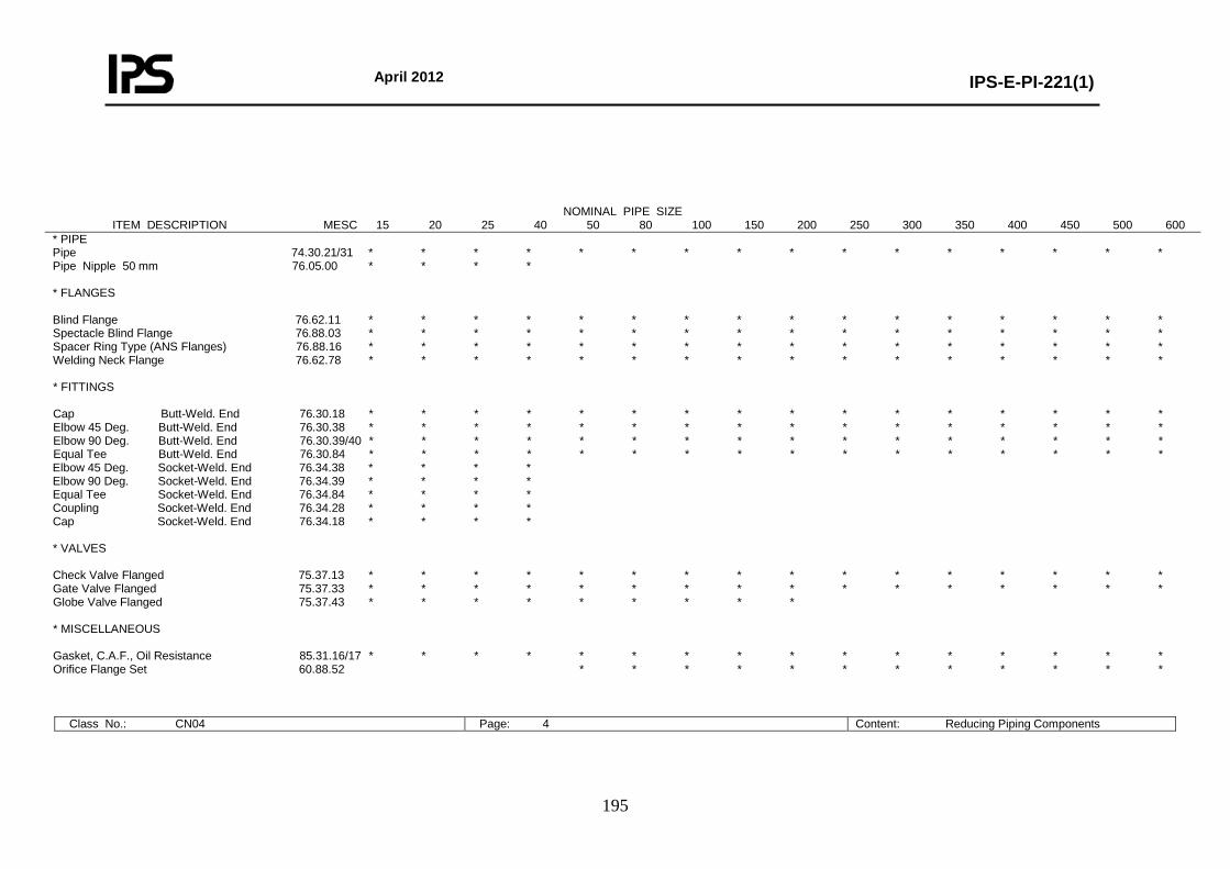
April 2012
IPS-E-PI-221(1)
195
Class No.: CN04 Page: 4 Content: Reducing Piping Components
NOMINAL PIPE SIZE ITEM DESCRIPTION MESC 15 20 25 40 50 80 100 150 200 250 300 350 400 450 500 600
* PIPE Pipe 74.30.21/31 * * * * * * * * * * * * * * * * Pipe Nipple 50 mm 76.05.00 * * * * * FLANGES Blind Flange 76.62.11 * * * * * * * * * * * * * * * * Spectacle Blind Flange 76.88.03 * * * * * * * * * * * * * * * * Spacer Ring Type (ANS Flanges) 76.88.16 * * * * * * * * * * * * * * * * Welding Neck Flange 76.62.78 * * * * * * * * * * * * * * * * * FITTINGS Cap Butt-Weld. End 76.30.18 * * * * * * * * * * * * * * * * Elbow 45 Deg. Butt-Weld. End 76.30.38 * * * * * * * * * * * * * * * * Elbow 90 Deg. Butt-Weld. End 76.30.39/40 * * * * * * * * * * * * * * * * Equal Tee Butt-Weld. End 76.30.84 * * * * * * * * * * * * * * * * Elbow 45 Deg. Socket-Weld. End 76.34.38 * * * * Elbow 90 Deg. Socket-Weld. End 76.34.39 * * * * Equal Tee Socket-Weld. End 76.34.84 * * * * Coupling Socket-Weld. End 76.34.28 * * * * Cap Socket-Weld. End 76.34.18 * * * * * VALVES Check Valve Flanged 75.37.13 * * * * * * * * * * * * * * * * Gate Valve Flanged 75.37.33 * * * * * * * * * * * * * * * * Globe Valve Flanged 75.37.43 * * * * * * * * * * MISCELLANEOUS Gasket, C.A.F., Oil Resistance 85.31.16/17 * * * * * * * * * * * * * * * * Orifice Flange Set 60.88.52 * * * * * * * * * * * *
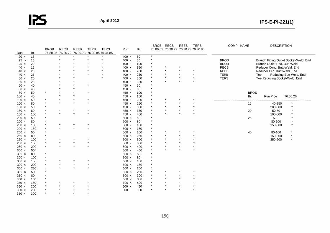
April 2012
IPS-E-PI-221(1)
196
BROB RECB REEB TERB TERS Run Br. 76.80.05 76.30.72 76.30.73 76.30.85 76.34.85
BROB RECB REEB TERB Run Br. 76.80.05 76.30.72 76.30.73 76.30.85
COMP. NAME DESCRIPTION
20 × 15 * * * * 25 × 15 * * * * 25 × 20 * * * * 40 × 15 * * * * 40 × 20 * * * * 40 × 25 * * * * 50 × 20 * * * 50 × 25 * * 50 × 40 * * * 80 × 40 * * 80 × 50 * * * * 100 × 40 * * 100 × 50 * * * * 100 × 80 * * * * 150 × 50 * 150 × 80 * * * * 150 × 100 * * * * 200 × 50 * 200 × 80 * 200 × 100 * * * * 200 × 150 * * * * 250 × 50 * 250 × 80 * 250 × 100 * * * * 250 × 150 * * * * 250 × 200 * * * * 300 × 50* 300 × 80 * 300 × 100 * 300 × 150 * * * * 300 × 200 * * * * 300 × 250 * * * * 350 × 50 * 350 × 80 * 350 × 100 * 350 × 150 * * * * 350 × 200 * * * * 350 × 250 * * * * 350 × 300 * * * *
400 × 50 * 400 × 80 * 400 × 100 * 400 × 150 * * * 400 × 200 * * * * 400 × 250 * * * * 400 × 300 * * * * 400 × 350 * * * * 450 × 50 * 450 × 80 * 450 × 100 * 450 × 150 * 450 × 200 * * * * 450 × 250 * * * * 450 × 300 * * * * 450 × 350 * * * * 450 × 400 * * * * 500 × 50 * 500 × 80 * 500 × 100 * 500 × 150 * 500 × 200 * * * * 500 × 250 * * * * 500 × 300 * * * * 500 × 350 * * * * 500 × 400 * * * * 500 × 450 * * * * 600 × 50 * 600 × 80 * 600 × 100 * 600 × 150 * 600 × 200 * 600 × 250 * * * * 600 × 300 * * * * 600 × 350 * * * * 600 × 400 * * * * 600 × 450 * * * * 600 × 500 * * * *
BROS Branch Fitting Outlet Socket-Weld. End BROB Branch Outlet Red. Butt-Weld RECB Reducer Conc. Butt-Weld. End REEB Reducer Ecc. Butt-Weld. End TERB Tee Reducing Butt-Weld. End TERS Tee Reducing Socket-Weld. End BROS Br. Run Pipe 76.80.26 --------------------------------------------------------------------------------------------- 15 40-150 * 200-600 * 20 50-80 * 100-600 * 25 50 * 80-100 * 150-600 * 40 80-100 * 150-300 * 350-600 *
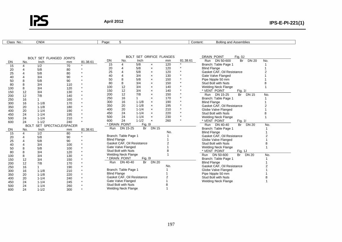
April 2012
IPS-E-PI-221(1)
197
Class No.: CN04 Page: 5 Content: Bolting and Assemblies
BOLT SET FLANGED JOINTS DN No. Inch mm 81.38.61 15 4 1/2 70 * 20 4 5/8 80 * 25 4 5/8 80 * 40 4 3/4 90 * 50 8 5/8 90 * 80 8 3/4 110 * 100 8 3/4 120 * 150 12 3/4 130 * 200 12 7/8 140 * 250 16 1 160 * 300 16 1-1/8 170 * 350 20 1-1/8 180 * 400 20 1-1/4 190 * 450 24 1-1/4 195 * 500 24 1-1/4 210 * 600 24 1-1/2 240 *
BOLT SET SPECTACLE/SPACER DN No. Inch mm 81.38.61 15 4 1/2 80 * 20 4 5/8 90 * 25 4 5/8 90 * 40 4 3/4 100 * 50 8 5/8 100 * 80 8 3/4 120 * 100 8 3/4 130 * 150 12 3/4 150 * 200 12 7/8 170 * 250 16 1 190 * 300 16 1-1/8 210 * 350 20 1-1/8 220 * 400 20 1-1/4 240 * 450 24 1-1/4 245 * 500 24 1-1/4 260 * 600 24 1-1/2 300 *
BOLT SET ORIFICE FLANGES DN No. Inch mm 81.38.61 15 4 5/8 × 120 * 20 4 5/8 × 120 * 25 4 5/8 × 120 * 40 4 3/4 × 130 * 50 8 5/8 × 150 * 80 8 3/4 × 150 * 100 12 3/4 × 140 * 150 12 3/4 × 140 * 200 12 7/8 × 150 * 250 16 1 × 170 * 300 16 1-1/8 × 190 * 350 20 1-1/8 × 195 * 400 20 1-1/4 × 210 * 450 24 1-1/4 × 220 * 500 24 1-1/4 × 230 * 600 24 1-1/2 × 260 * * DRAIN POINT Fig. 0I Run DN 15-25 Br DN 15 No. Branch: Table Page 1 1 Blind Flange 1 Gasket CAF, Oil Resistance 2 Gate Valve Flanged 1 Stud Bolt with Nuts 8 Welding Neck Flange 1 * DRAIN POINT Fig. 0I Run DN 40-40 Br DN 20 No. Branch: Table Page 1 1 Blind Flange 1 Gasket CAF, Oil Resistance 2 Gate Valve Flanged 1 Stud Bolt with Nuts 8 Welding Neck Flange 1
DRAIN POINT Fig. 0J Run DN 50-600 Br DN 20 No. Branch: Table Page 1 1 Blind Flange 1 Gasket CAF, Oil Resistance 2 Gate Valve Flanged 1 Pipe Nipple 50 mm 1 Stud Bolt with Nuts 8 Welding Neck Flange 1 * VENT POINT Fig. 1I Run DN 15-25 Br DN 15 No. Branch: Table Page 1 1 Blind Flange 1 Gasket CAF, Oil Resistance 2 Globe Valve Flanged 1 Stud Bolt with Nuts 8 Welding Neck Flange 1 * VENT POINT Fig. 1I Run DN 40-40 Br DN 20 No. Branch: Table Page 1 1 Blind Flange 1 Gasket CAF, Oil Resistance 2 Globe Valve Flanged 1 Stud Bolt with Nuts 8 Welding Neck Flange 1 * VENT POINT Fig. 1J Run DN 50-600 Br DN 20 No. Branch: Table Page 1 1 Blind Flange 1 Gasket CAF, Oil Resistance 2 Globe Valve Flanged 1 Pipe Nipple 50 mm 1 Stud Bolt with Nuts 8 Welding Neck Flange 1
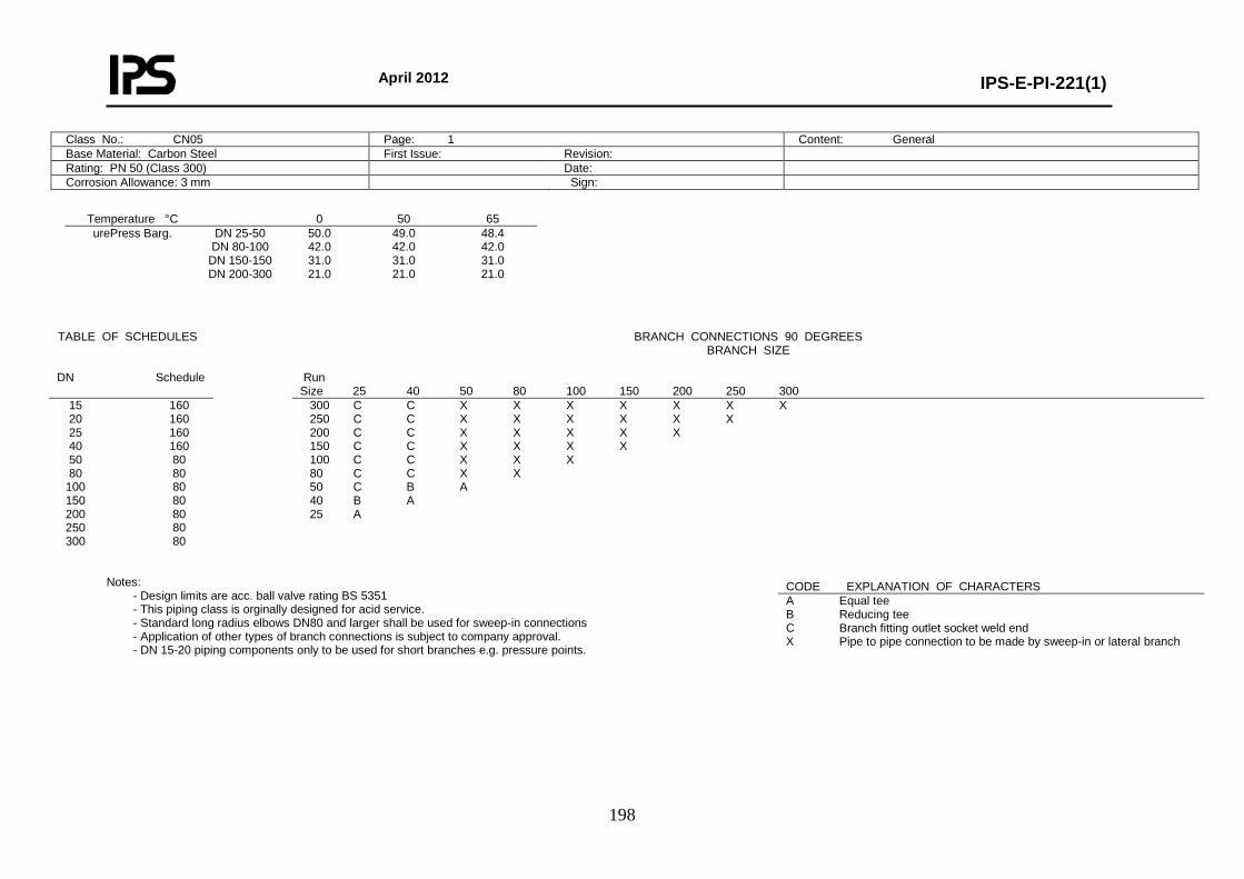
April 2012
IPS-E-PI-221(1)
198
Class No.: CN05 Page: 1 Content: General Base Material: Carbon Steel First Issue: Revision: Rating: PN 50 (Class 300) Date: Corrosion Allowance: 3 mm Sign:
Temperature °C 0 50 65 urePress Barg.
DN 25-50 DN 80-100
DN 150-150 DN 200-300
50.0 42.0 31.0 21.0
49.0 42.0 31.0 21.0
48.4 42.0 31.0 21.0
Notes:
- Design limits are acc. ball valve rating BS 5351 - This piping class is orginally designed for acid service. - Standard long radius elbows DN80 and larger shall be used for sweep-in connections - Application of other types of branch connections is subject to company approval. - DN 15-20 piping components only to be used for short branches e.g. pressure points.
TABLE OF SCHEDULES BRANCH CONNECTIONS 90 DEGREES BRANCH SIZE
DN Schedule Run
Size 25 40 50 80 100 150 200 250 300 15 20 25 40 50 80
100 150 200 250 300
160 160 160 160 80 80 80 80 80 80 80
300 C C X X X X X X X 250 C C X X X X X X 200 C C X X X X X 150 C C X X X X 100 C C X X X 80 C C X X 50 C B A 40 B A 25 A
CODE EXPLANATION OF CHARACTERS A Equal tee B Reducing tee C Branch fitting outlet socket weld end X Pipe to pipe connection to be made by sweep-in or lateral branch
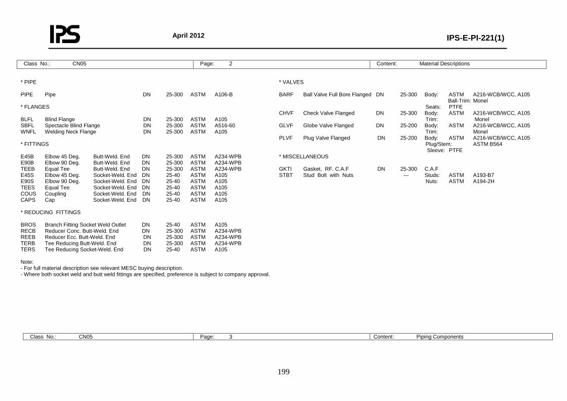
April 2012
IPS-E-PI-221(1)
199
Class No.: CN05 Page: 2 Content: Material Descriptions
* PIPE PIPE Pipe DN 25-300 ASTM A106-B * FLANGES BLFL Blind Flange DN 25-300 ASTM A105 SBFL Spectacle Blind Flange DN 25-300 ASTM A516-60 WNFL Welding Neck Flange DN 25-300 ASTM A105 * FITTINGS E45B Elbow 45 Deg. Butt-Weld. End DN 25-300 ASTM A234-WPB E90B Elbow 90 Deg. Butt-Weld. End DN 25-300 ASTM A234-WPB TEEB Equal Tee Butt-Weld. End DN 25-300 ASTM A234-WPB E45S Elbow 45 Deg. Socket-Weld. End DN 25-40 ASTM A105 E90S Elbow 90 Deg. Socket-Weld. End DN 25-40 ASTM A105 TEES Equal Tee Socket-Weld. End DN 25-40 ASTM A105 COUS Coupling Socket-Weld. End DN 25-40 ASTM A105 CAPS Cap Socket-Weld. End DN 25-40 ASTM A105 * REDUCING FITTINGS BROS Branch Fitting Socket Weld Outlet DN 25-40 ASTM A105 RECB Reducer Conc. Butt-Weld. End DN 25-300 ASTM A234-WPB REEB Reducer Ecc. Butt-Weld. End DN 25-300 ASTM A234-WPB TERB Tee Reducing Butt-Weld. End DN 25-300 ASTM A234-WPB TERS Tee Reducing Socket-Weld. End DN 25-40 ASTM A105 Note: - For full material description see relevant MESC buying description. - Where both socket weld and butt weld fittings are specified, preference is subject to company approval.
* VALVES BARF Ball Valve Full Bore Flanged DN 25-300 Body: ASTM A216-WCB/WCC, A105 Ball-Trim: Monel Seats: PTFE CHVF Check Valve Flanged DN 25-300 Body: ASTM A216-WCB/WCC, A105 Trim: Monel GLVF Globe Valve Flanged DN 25-200 Body: ASTM A216-WCB/WCC, A105 Trim: Monel PLVF Plug Valve Flanged DN 25-200 Body: ASTM A216-WCB/WCC, A105 Plug/Stem: ASTM B564 Sleeve: PTFE * MISCELLANEOUS GKTI Gasket, RF. C.A.F DN 25-300 C.A.F STBT Stud Bolt with Nuts --- Studs: ASTM A193-B7 Nuts: ASTM A194-2H
Class No.: CN05 Page: 3 Content: Piping Components
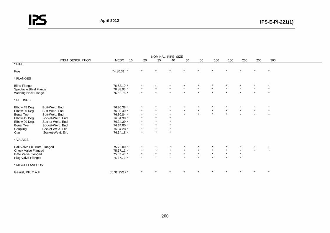
April 2012
IPS-E-PI-221(1)
200
NOMINAL PIPE SIZE ITEM DESCRIPTION MESC 15 20 25 40 50 80 100 150 200 250 300
* PIPE Pipe 74.30.31 * * * * * * * * * * * * FLANGES Blind Flange 76.62.10 * * * * * * * * * * * Spectacle Blind Flange 76.88.06 * * * * * * * * * * * Welding Neck Flange 76.62.78 * * * * * * * * * * * * FITTINGS Elbow 45 Deg. Butt-Weld. End 76.30.38 * * * * * * * * * * * Elbow 90 Deg. Butt-Weld. End 76.30.40 * * * * * * * * * * * Equal Tee Butt-Weld. End 76.30.84 * * * * * * * * * * * Elbow 45 Deg. Socket-Weld. End 76.34.38 * * * * Elbow 90 Deg. Socket-Weld. End 76.34.39 * * * * Equal Tee Socket-Weld. End 76.34.80 * * * * Coupling Socket-Weld. End 76.34.28 * * * * Cap Socket-Weld. End 76.34.18 * * * * * VALVES Ball Valve Full Bore Flanged 75.72.00 * * * * * * * * * * * Check Valve Flanged 75.37.13 * * * * * * * * * * * Gate Valve Flanged 75.37.43 * * * * * * * * * Plug Valve Flanged 75.37.73 * * * * * * * * * * MISCELLANEOUS Gasket, RF. C.A.F 85.31.15/17 * * * * * * * * * * *
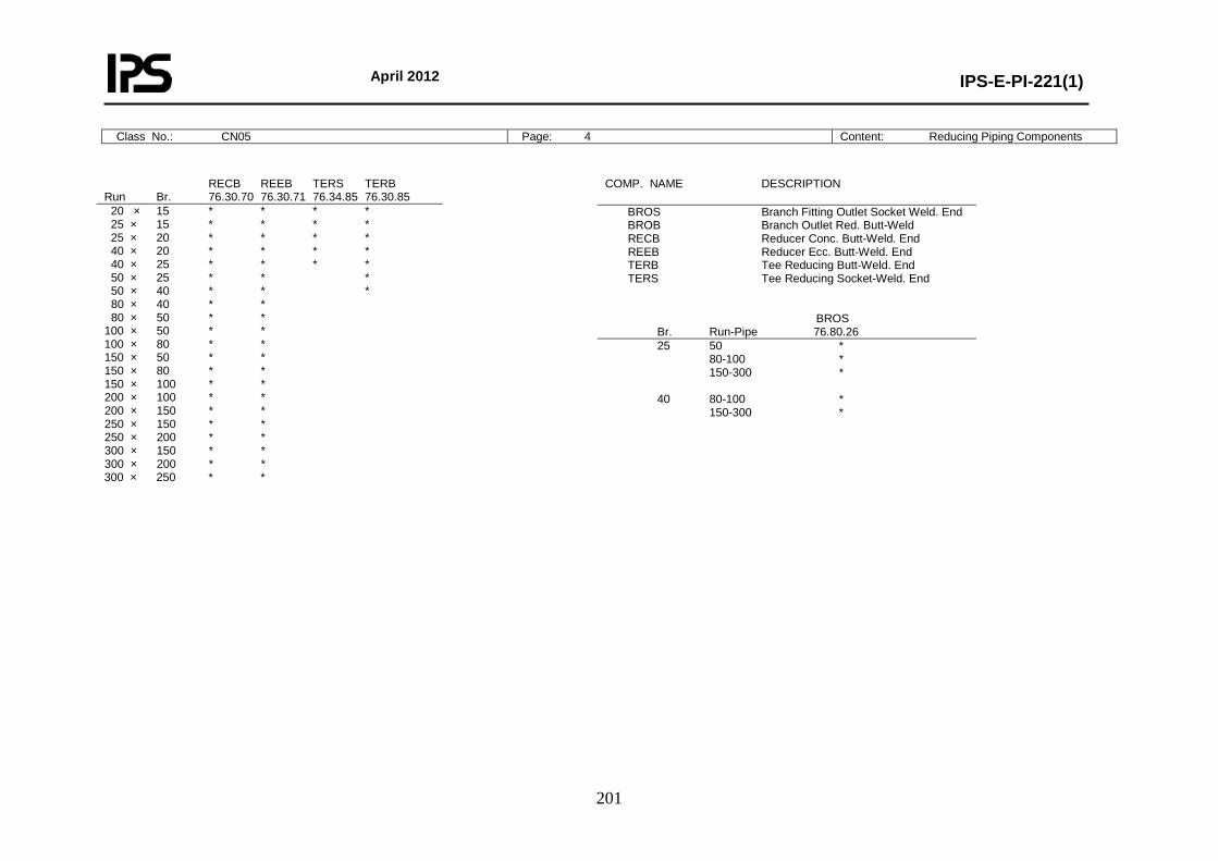
April 2012
IPS-E-PI-221(1)
201
Class No.: CN05 Page: 4 Content: Reducing Piping Components
RECB REEB TERS TERB Run Br. 76.30.70 76.30.71 76.34.85 76.30.85 20 × 15 * * * * 25 × 15 * * * * 25 × 20 * * * * 40 × 20 * * * * 40 × 25 * * * * 50 × 25 * * * 50 × 40 * * * 80 × 40 * * 80 × 50 * * 100 × 50 * * 100 × 80 * * 150 × 50 * * 150 × 80 * * 150 × 100 * * 200 × 100 * * 200 × 150 * * 250 × 150 * * 250 × 200 * * 300 × 150 * * 300 × 200 * * 300 × 250 * *
COMP. NAME DESCRIPTION
BROS Branch Fitting Outlet Socket Weld. End BROB Branch Outlet Red. Butt-Weld RECB Reducer Conc. Butt-Weld. End REEB Reducer Ecc. Butt-Weld. End TERB Tee Reducing Butt-Weld. End TERS Tee Reducing Socket-Weld. End BROS Br. Run-Pipe 76.80.26 25 50 * 80-100 * 150-300 * 40 80-100 * 150-300 *
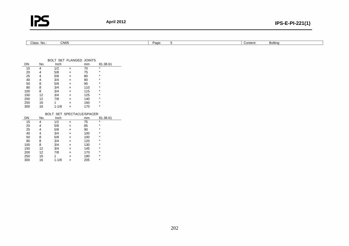
April 2012
IPS-E-PI-221(1)
202
Class No.: CN05 Page: 5 Content: Bolting
BOLT SET FLANGED JOINTS DN No. Inch mm 81.38.61 15 4 1/2 × 70 * 20 4 5/8 × 75 * 25 4 5/8 × 80 * 40 4 3/4 × 90 * 50 8 5/8 × 90 * 80 8 3/4 × 110 * 100 8 3/4 × 115 * 150 12 3/4 × 125 * 200 12 7/8 × 140 * 250 16 1 × 160 * 300 16 1-1/8 × 170 *
BOLT SET SPECTACLE/SPACER DN No. Inch mm 81.38.61 15 4 1/2 × 75 * 20 4 5/8 × 85 * 25 4 5/8 × 90 * 40 4 3/4 × 100 * 50 8 5/8 × 100 * 80 8 3/4 × 120 * 100 8 3/4 × 130 * 150 12 3/4 × 145 * 200 12 7/8 × 170 * 250 16 1 × 190 * 300 16 1-1/8 × 205 *
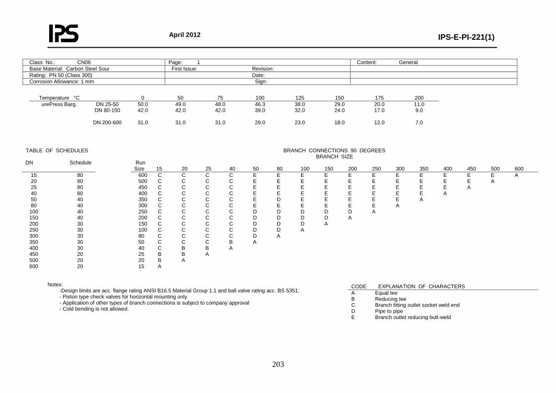
April 2012
IPS-E-PI-221(1)
203
Class No.: CN06 Page: 1 Content: General Base Material: Carbon Steel Sour First Issue: Revision: Rating: PN 50 (Class 300) Date: Corrosion Allowance: 1 mm Sign:
Temperature °C 0 50 75 100 125 150 175 200 urePress Barg.
DN 25-50 DN 80-150
DN 200-600
50.0 42.0
31.0
49.0 42.0
31.0
48.0 42.0
31.0
46.3 39.0
29.0
38.0 32.0
23.0
29.0 24.0
18.0
20.0 17.0
12.0
11.0 9.0
7.0
Notes:
-Design limits are acc. flange rating ANSI B16.5 Material Group 1.1 and ball valve rating acc. BS 5351. - Piston type check valves for horizontal mounting only. - Application of other types of branch connections is subject to company approval - Cold bending is not allowed.
TABLE OF SCHEDULES BRANCH CONNECTIONS 90 DEGREES BRANCH SIZE
DN Schedule Run Size 15 20 25 40 50 80 100 150 200 250 300 350 400 450 500 600
15 20 25 40 50 80
100 150 200 250 300 350 400 450 500 600
80 80 80 80 40 40 40 40 30 30 30 30 30 20 20 20
600 C C C C E E E E E E E E E E E A 500 C C C C E E E E E E E E E E A 450 C C C C E E E E E E E E E A 400 C C C C E E E E E E E E A 350 C C C C E D E E E E E A 300 C C C C E E E E E E A 250 C C C C D D D D D A 200 C C C C D D D D A 150 C C C C D D D A 100 C C C C D D A 80 C C C C D A 50 C C C B A 40 C B B A 25 B B A 20 B A 15 A
CODE EXPLANATION OF CHARACTERS A Equal tee B Reducing tee C Branch fitting outlet socket weld end D Pipe to pipe E Branch outlet reducing butt-weld
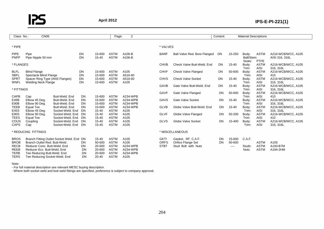
April 2012
IPS-E-PI-221(1)
204
Class No.: CN06 Page: 2 Content: Material Descriptions
* PIPE PIPE Pipe DN 15-600 ASTM A106-B PNPP Pipe Nipple 50 mm DN 15-40 ASTM A106-B * FLANGES BLFL Blind Flange DN 15-600 ASTM A105 SBFL Spectacle Blind Flange DN 15-600 ASTM A516-60 SPRT Spacer Ring Type (ANS Flanges) DN 15-600 ASTM A516-60 WNFL Welding Neck Flange DN 15-600 ASTM A105 * FITTINGS CAPB Cap Butt-Weld. End DN 15-600 ASTM A234-WPB E45B Elbow 45 Deg. Butt-Weld. End DN 15-600 ASTM A234-WPB E90B Elbow 90 Deg. Butt-Weld. End DN 15-600 ASTM A234-WPB TEEB Equal Tee Butt-Weld. End DN 15-600 ASTM A234-WPB E45S Elbow 45 Deg. Socket-Weld. End DN 15-40 ASTM A105 E90S Elbow 90 Deg. Socket-Weld. End DN 15-40 ASTM A105 TEES Equal Tee Socket-Weld. End DN 15-40 ASTM A105 COUS Coupling Socket-Weld. End DN 15-40 ASTM A105 CAPS Cap Socket-Weld. End DN 15-40 ASTM A105 * REDUCING FITTINGS BROS Branch Fitting Outlet Socket Weld. End DN 15-40 ASTM A105 BROB Branch Outlet Red. Butt-Weld . DN 50-600 ASTM A105 RECB Reducer Conc. Butt-Weld. End DN 20-600 ASTM A234-WPB REEB Reducer Ecc. Butt-Weld. End DN 20-600 ASTM A234-WPB TERB Tee Reducing Butt-Weld. End DN 20-600 ASTM A234-WPB TERS Tee Reducing Socket-Weld. End DN 20-40 ASTM A105 Note: - For full material description see relevant MESC buying description. - Where both socket weld and butt weld fittings are specified, preference is subject to company approval.
* VALVES BARF Ball Valve Red. Bore Flanged DN 15-250 Body: ASTM A216-WCB/WCC, A105 Ball/Stem: AISI 316, 316L Seats: PTFE CHVB Check Valve Butt-Weld. End DN 15-40 Body: ASTM A216-WCB/WCC, A105 Trim: AISI 316, 316L CHVF Check Valve Flanged DN 50-600 Body: ASTM A216-WCB/WCC, A105 Trim: AISI 410 CHVS Check Valve Socket DN 15-40 Body: ASTM A216-WCB/WCC, A105 Trim: AISI 316, 316L GAVB Gate Valve Butt-Weld. End DN 15-40 Body: ASTM A216-WCB/WCC, A105 Trim: AISI 316, 316L GAVF Gate Valve Flanged DN 50-600 Body: ASTM A216-WCB/WCC, A105 Trim: AISI 410 GAVS Gate Valve Socket DN 15-40 Body: ASTM A216-WCB/WCC, A105 Trim: AISI 316, 316L GLVB Globe Valve Butt-Weld. End DN 15-40 Body: ASTM A216-WCB/WCC, A105 Trim: AISI 316, 316L GLVF Globe Valve Flanged DN 50-200 Body: ASTM A216-WCB/WCC, A105 Trim: AISI 410 GLVS Globe Valve Socket DN 15-400 Body: ASTM A216-WCB/WCC, A105 Trim: AISI 316, 316L * MISCELLANEOUS GKTI Gasket, RF. C.A.F. DN 15-600 C.A.F. ORFS Orifice Flange Set DN 50-600 ASTM A105 STBT Stud Bolt with Nuts ---- Studs: ASTM A193-B7M Nuts: ASTM A194-2HM

April 2012
IPS-E-PI-221(1)
205
Class No.: CN06 Page: 3 Content: Piping Components
NOMINAL PIPE SIZE ITEM DESCRIPTION MESC 15 20 25 40 50 80 100 150 200 250 300 350 400 450 500 600
* PIPE Pipe 74.30.31 * * * * * * * * * * * * * * * * Pipe Nipple 50 mm 76.05.56 * * * * * FLANGES Blind Flange 76.62.10 * * * * * * * * * * * * * * * * Spectacle Blind Flange 76.88.06 * * * * * * * * * * * * * * * * Spacer Ring Type (ANS Flanges) 76.88.00 * * * * * * * * * * * * * * * * Welding Neck Flange 76.62.79 * * * * * * * * * * * * * * * * * FITTINGS Cap Butt-Weld. End 76.30.18 * * * * * * * * * * * * * * * * Elbow 45 Deg. Butt-Weld. End 76.30.38 * * * * * * * * * * * * * * * * Elbow 90 Deg. Butt-Weld. End 76.30.40 * * * * * * * * * * * * * * * * Equal Tee Butt-Weld. End 76.30.84 * * * * * * * * * * * * * * * * Elbow 45 Deg. Socket-Weld. End 76.34.38 * * * * Elbow 90 Deg. Socket-Weld. End 76.34.39 * * * * Equal Tee Socket-Weld. End 76.34.80 * * * * Coupling Socket-Weld. End 76.34.28 * * * * Cap Socket-Weld. End 76.34.18 * * * * * VALVES Ball Valve Red. Bore Flanged 75.37.00 * * * * * * * * * * Check Valve Butt-Weld. End 75.56.19 * * * * Check Valve Flanged 75.37.13 * * * * * * * * * * * * Check Valve Socket 75.56.13 * * * * Gate Valve Butt-Weld. End 75.56.38 * * * * Gate Valve Flanged 75.37.33 * * * * * * * * * * * * Gate Valve Socket 75.56.35 * * * * Globe Valve Butt-Weld. End 75.56.50 * * * * Globe Valve Flanged 75.37.43 * * * * * Globe Valve Socket 75.56.45 * * * * *MISCELLANEOUS Gasket, RF. C.A.F. 85.31.15/17 * * * * * * * * * * * * * * * * Orifice Flange Set 60.88.52 * * * * * * * * * * * *
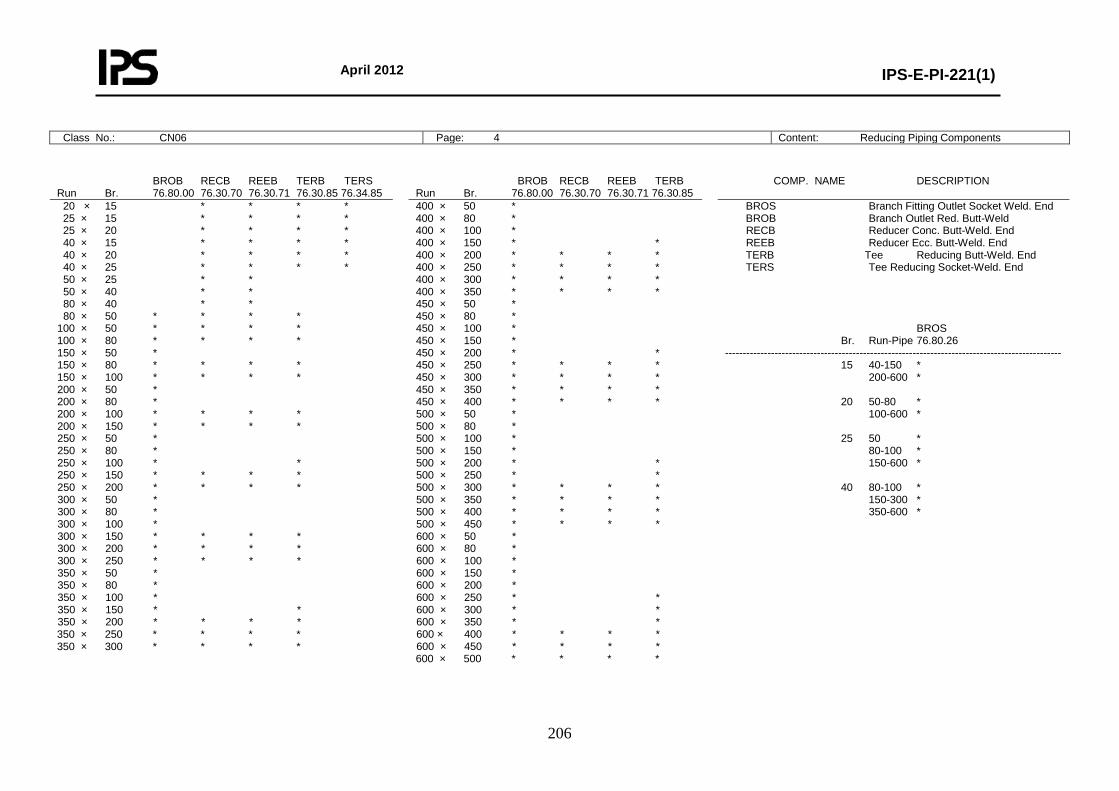
April 2012
IPS-E-PI-221(1)
206
Class No.: CN06 Page: 4 Content: Reducing Piping Components
BROB RECB REEB TERB TERS Run Br. 76.80.00 76.30.70 76.30.71 76.30.85 76.34.85
BROB RECB REEB TERB Run Br. 76.80.00 76.30.70 76.30.71 76.30.85
COMP. NAME DESCRIPTION
20 × 15 * * * * 25 × 15 * * * * 25 × 20 * * * * 40 × 15 * * * * 40 × 20 * * * * 40 × 25 * * * * 50 × 25 * * 50 × 40 * * 80 × 40 * * 80 × 50 * * * * 100 × 50 * * * * 100 × 80 * * * * 150 × 50 * 150 × 80 * * * * 150 × 100 * * * * 200 × 50 * 200 × 80 * 200 × 100 * * * * 200 × 150 * * * * 250 × 50 * 250 × 80 * 250 × 100 * * 250 × 150 * * * * 250 × 200 * * * * 300 × 50 * 300 × 80 * 300 × 100 * 300 × 150 * * * * 300 × 200 * * * * 300 × 250 * * * * 350 × 50 * 350 × 80 * 350 × 100 * 350 × 150 * * 350 × 200 * * * * 350 × 250 * * * * 350 × 300 * * * *
400 × 50 * 400 × 80 * 400 × 100 * 400 × 150 * * 400 × 200 * * * * 400 × 250 * * * * 400 × 300 * * * * 400 × 350 * * * * 450 × 50 * 450 × 80 * 450 × 100 * 450 × 150 * 450 × 200 * * 450 × 250 * * * * 450 × 300 * * * * 450 × 350 * * * * 450 × 400 * * * * 500 × 50 * 500 × 80 * 500 × 100 * 500 × 150 * 500 × 200 * * 500 × 250 * * 500 × 300 * * * * 500 × 350 * * * * 500 × 400 * * * * 500 × 450 * * * * 600 × 50 * 600 × 80 * 600 × 100 * 600 × 150 * 600 × 200 * 600 × 250 * * 600 × 300 * * 600 × 350 * * 600 × 400 * * * * 600 × 450 * * * * 600 × 500 * * * *
BROS Branch Fitting Outlet Socket Weld. End BROB Branch Outlet Red. Butt-Weld RECB Reducer Conc. Butt-Weld. End REEB Reducer Ecc. Butt-Weld. End TERB Tee Reducing Butt-Weld. End TERS Tee Reducing Socket-Weld. End BROS Br. Run-Pipe 76.80.26 ----------------------------------------------------------------------------------------------- 15 40-150 * 200-600 * 20 50-80 * 100-600 * 25 50 * 80-100 * 150-600 * 40 80-100 * 150-300 * 350-600 *
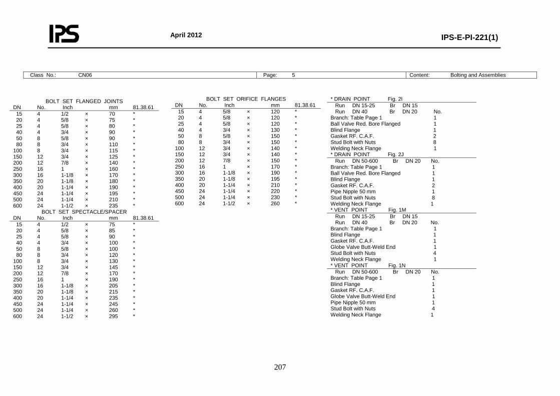
April 2012
IPS-E-PI-221(1)
207
Class No.: CN06 Page: 5 Content: Bolting and Assemblies
BOLT SET FLANGED JOINTS DN No. Inch mm 81.38.61 15 4 1/2 × 70 * 20 4 5/8 × 75 * 25 4 5/8 × 80 * 40 4 3/4 × 90 * 50 8 5/8 × 90 * 80 8 3/4 × 110 * 100 8 3/4 × 115 * 150 12 3/4 × 125 * 200 12 7/8 × 140 * 250 16 1 × 160 * 300 16 1-1/8 × 170 * 350 20 1-1/8 × 180 * 400 20 1-1/4 × 190 * 450 24 1-1/4 × 195 * 500 24 1-1/4 × 210 * 600 24 1-1/2 × 235 *
BOLT SET SPECTACLE/SPACER DN No. Inch mm 81.38.61 15 4 1/2 × 75 * 20 4 5/8 × 85 * 25 4 5/8 × 90 * 40 4 3/4 × 100 * 50 8 5/8 × 100 * 80 8 3/4 × 120 * 100 8 3/4 × 130 * 150 12 3/4 × 145 * 200 12 7/8 × 170 * 250 16 1 × 190 * 300 16 1-1/8 × 205 * 350 20 1-1/8 × 215 * 400 20 1-1/4 × 235 * 450 24 1-1/4 × 245 * 500 24 1-1/4 × 260 * 600 24 1-1/2 × 295 *
BOLT SET ORIFICE FLANGES DN No. Inch mm 81.38.61 15 4 5/8 × 120 * 20 4 5/8 × 120 * 25 4 5/8 × 120 * 40 4 3/4 × 130 * 50 8 5/8 × 150 * 80 8 3/4 × 150 * 100 12 3/4 × 140 * 150 12 3/4 × 140 * 200 12 7/8 × 150 * 250 16 1 × 170 * 300 16 1-1/8 × 190 * 350 20 1-1/8 × 195 * 400 20 1-1/4 × 210 * 450 24 1-1/4 × 220 * 500 24 1-1/4 × 230 * 600 24 1-1/2 × 260 *
* DRAIN POINT Fig. 2I Run DN 15-25 Br DN 15 Run DN 40 Br DN 20 No. Branch: Table Page 1 1 Ball Valve Red. Bore Flanged 1 Blind Flange 1 Gasket RF. C.A.F. 2 Stud Bolt with Nuts 8 Welding Neck Flange 1 * DRAIN POINT Fig. 2J Run DN 50-600 Br DN 20 No. Branch: Table Page 1 1 Ball Valve Red. Bore Flanged 1 Blind Flange 1 Gasket RF. C.A.F. 2 Pipe Nipple 50 mm 1 Stud Bolt with Nuts 8 Welding Neck Flange 1 * VENT POINT Fig. 1M Run DN 15-25 Br DN 15 Run DN 40 Br DN 20 No. Branch: Table Page 1 1 Blind Flange 1 Gasket RF. C.A.F. 1 Globe Valve Butt-Weld End 1 Stud Bolt with Nuts 4 Welding Neck Flange 1 * VENT POINT Fig. 1N Run DN 50-600 Br DN 20 No. Branch: Table Page 1 1 Blind Flange 1 Gasket RF. C.A.F. 1 Globe Valve Butt-Weld End 1 Pipe Nipple 50 mm 1 Stud Bolt with Nuts 4 Welding Neck Flange 1
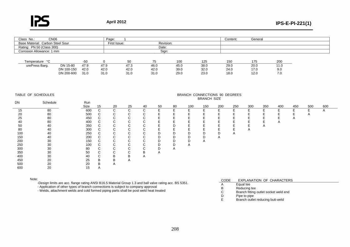
April 2012
IPS-E-PI-221(1)
208
Class No.: CN06 Page: 1 Content: General Base Material: Carbon Steel Sour First Issue: Revision: Rating: PN 50 (Class 300) Date: Corrosion Allowance: 1 mm Sign:
Temperature °C -50 0 50 75 100 125 150 175 200 urePress Barg.
DN 15-80 DN 100-150 DN 200-600
47.9 42.0 31.0
47.9 42.0 31.0
47.3 42.0 31.0
46.0 42.0 31.0
45.0 39.0 29.0
38.0 32.0 23.0
29.0 24.0 18.0
20.0 17.0 12.0
11.0 9.0 7.0
Note:
-Design limits are acc. flange rating ANSI B16.5 Material Group 1.3 and ball valve rating acc. BS 5351. - Application of other types of branch connections is subject to company approval - Welds, attachment welds and cold formed piping parts shall be post weld heat treated
TABLE OF SCHEDULES BRANCH CONNECTIONS 90 DEGREES BRANCH SIZE
DN Schedule Run Size 15 20 25 40 50 80 100 150 200 250 300 350 400 450 500 600
15 20 25 40 50 80
100 150 200 250 300 350 400 450 500 600
80 80 80 80 40 40 40 40 30 30 30 30 30 20 20 20
600 C C C C E E E E E E E E E E E A 500 C C C C E E E E E E E E E E A 450 C C C C E E E E E E E E E A 400 C C C C E E E E E E E E A 350 C C C C E D E E E E E A 300 C C C C E E E E E E A 250 C C C C D D D D D A 200 C C C C D D D D A 150 C C C C D D D A 100 C C C C D D A 80 C C C C D A 50 C C C B A 40 C B B A 25 B B A 20 B A 15 A
CODE EXPLANATION OF CHARACTERS A Equal tee B Reducing tee C Branch fitting outlet socket weld end D Pipe to pipe E Branch outlet reducing butt-weld
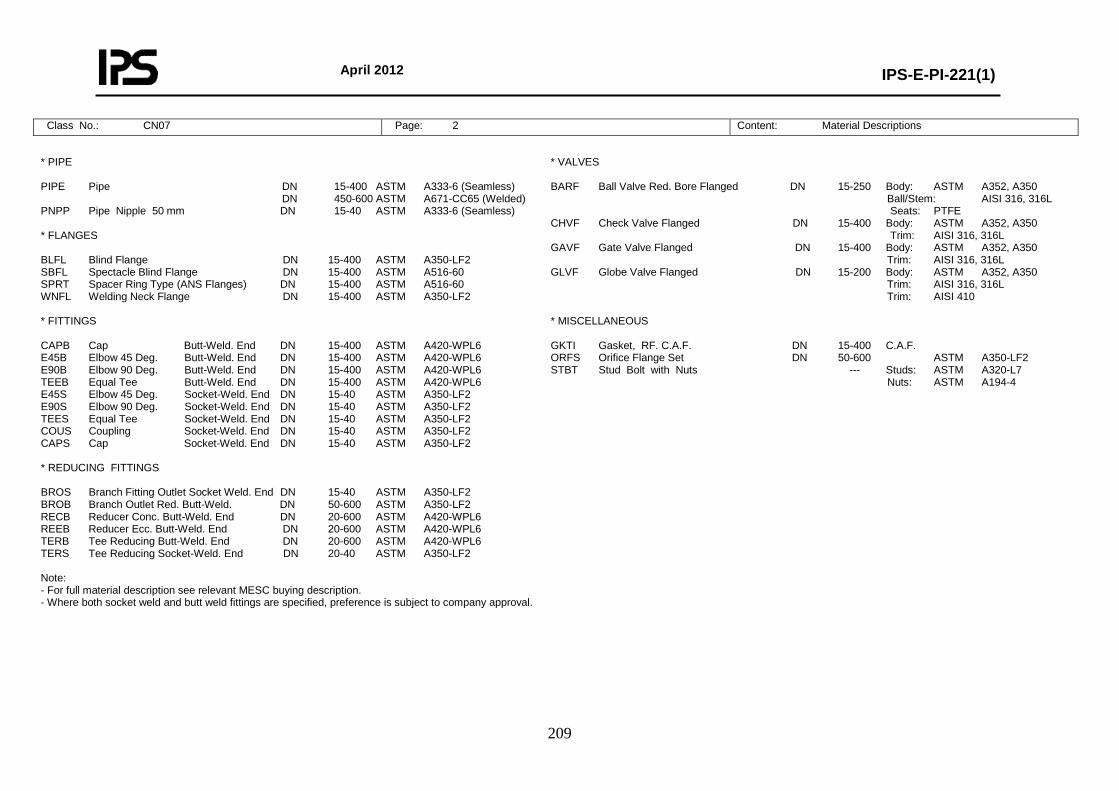
April 2012
IPS-E-PI-221(1)
209
Class No.: CN07 Page: 2 Content: Material Descriptions
* PIPE PIPE Pipe DN 15-400 ASTM A333-6 (Seamless) DN 450-600 ASTM A671-CC65 (Welded) PNPP Pipe Nipple 50 mm DN 15-40 ASTM A333-6 (Seamless) * FLANGES BLFL Blind Flange DN 15-400 ASTM A350-LF2 SBFL Spectacle Blind Flange DN 15-400 ASTM A516-60 SPRT Spacer Ring Type (ANS Flanges) DN 15-400 ASTM A516-60 WNFL Welding Neck Flange DN 15-400 ASTM A350-LF2 * FITTINGS CAPB Cap Butt-Weld. End DN 15-400 ASTM A420-WPL6 E45B Elbow 45 Deg. Butt-Weld. End DN 15-400 ASTM A420-WPL6 E90B Elbow 90 Deg. Butt-Weld. End DN 15-400 ASTM A420-WPL6 TEEB Equal Tee Butt-Weld. End DN 15-400 ASTM A420-WPL6 E45S Elbow 45 Deg. Socket-Weld. End DN 15-40 ASTM A350-LF2 E90S Elbow 90 Deg. Socket-Weld. End DN 15-40 ASTM A350-LF2 TEES Equal Tee Socket-Weld. End DN 15-40 ASTM A350-LF2 COUS Coupling Socket-Weld. End DN 15-40 ASTM A350-LF2 CAPS Cap Socket-Weld. End DN 15-40 ASTM A350-LF2 * REDUCING FITTINGS BROS Branch Fitting Outlet Socket Weld. End DN 15-40 ASTM A350-LF2 BROB Branch Outlet Red. Butt-Weld. DN 50-600 ASTM A350-LF2 RECB Reducer Conc. Butt-Weld. End DN 20-600 ASTM A420-WPL6 REEB Reducer Ecc. Butt-Weld. End DN 20-600 ASTM A420-WPL6 TERB Tee Reducing Butt-Weld. End DN 20-600 ASTM A420-WPL6 TERS Tee Reducing Socket-Weld. End DN 20-40 ASTM A350-LF2 Note: - For full material description see relevant MESC buying description. - Where both socket weld and butt weld fittings are specified, preference is subject to company approval.
* VALVES BARF Ball Valve Red. Bore Flanged DN 15-250 Body: ASTM A352, A350 Ball/Stem: AISI 316, 316L Seats: PTFE CHVF Check Valve Flanged DN 15-400 Body: ASTM A352, A350 Trim: AISI 316, 316L GAVF Gate Valve Flanged DN 15-400 Body: ASTM A352, A350 Trim: AISI 316, 316L GLVF Globe Valve Flanged DN 15-200 Body: ASTM A352, A350 Trim: AISI 316, 316L Trim: AISI 410 * MISCELLANEOUS GKTI Gasket, RF. C.A.F. DN 15-400 C.A.F. ORFS Orifice Flange Set DN 50-600 ASTM A350-LF2 STBT Stud Bolt with Nuts --- Studs: ASTM A320-L7 Nuts: ASTM A194-4
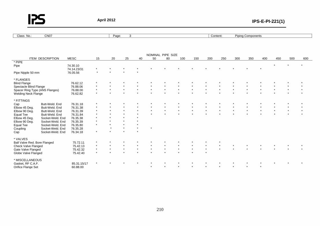
April 2012
IPS-E-PI-221(1)
210
Class No.: CN07 Page: 3 Content: Piping Components
NOMINAL PIPE SIZE ITEM DESCRIPTION MESC 15 20 25 40 50 80 100 150 200 250 300 350 400 450 500 600
* PIPE Pipe 74.30.10 * * * 74.14.23/31 * * * * * * * * * * * * * Pipe Nipple 50 mm 76.05.56 * * * * * FLANGES Blind Flange 76.62.12 * * * * * * * * * * * * * * * * Spectacle Blind Flange 76.88.06 * * * * * * * * * * * * * * * * Spacer Ring Type (ANS Flanges) 76.88.00 * * * * * * * * * * * * * * * * Welding Neck Flange 76.62.82 * * * * * * * * * * * * * * * * * FITTINGS Cap Butt-Weld. End 76.31.18 * * * * * * * * * * * * * * * * Elbow 45 Deg. Butt-Weld. End 76.31.38 * * * * * * * * * * * * * * * * Elbow 90 Deg. Butt-Weld. End 76.31.39 * * * * * * * * * * * * * * * * Equal Tee Butt-Weld. End 76.31.84 * * * * * * * * * * * * * * * * Elbow 45 Deg. Socket-Weld. End 76.35.38 * * * * Elbow 90 Deg. Socket-Weld. End 76.35.39 * * * * Equal Tee Socket-Weld. End 76.35.80 * * * * Coupling Socket-Weld. End 76.35.28 * * * * Cap Socket-Weld. End 76.34.18 * * * * * VALVES Ball Valve Red. Bore Flanged 75.72.11 * * * * * * * * * * Check Valve Flanged 75.42.13 * * * * * * * * * * * * * * * * Gate Valve Flanged 75.42.32 * * * * * * * * * * * * * * * * Globe Valve Flanged 75.42.40 * * * * * * * * * * MISCELLANEOUS Gasket, RF C.A.F. 85.31.15/17 * * * * * * * * * * * * * * * * Orifice Flange Set 60.88.00 * * * * * * * * *
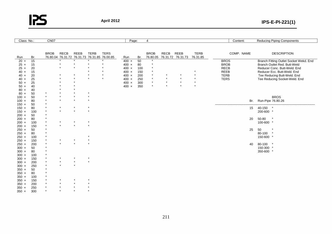
April 2012
IPS-E-PI-221(1)
211
Class No.: CN07 Page: 4 Content: Reducing Piping Components
BROB RECB REEB TERB TERS Run Br. 76.80.04 76.31.72 76.31.73 76.31.85 76.00.85
BROB RECB REEB TERB Run Br. 76.80.05 76.31.72 76.31.73 76.31.85
COMP. NAME DESCRIPTION
20 × 15 * * * * 25 × 15 * * * * 25 × 20 * * * * 40 × 15 * * 40 × 20 * * * * 40 × 25 * * * * 50 × 25 * * 50 × 40 * * 80 × 40 * * 80 × 50 * * * * 100 × 50 * * * * 100 × 80 * * * * 150 × 50 * 150 × 80 * * * * 150 × 100 * * * * 200 × 50 * 200 × 80 * 200 × 100 * * * * 200 × 150 * * * * 250 × 50 * 250 × 80 * 250 × 100 * * 250 × 150 * * * * 250 × 200 * * * * 300 × 50 * 300 × 80 * 300 × 100 * 300 × 150 * * * * 300 × 200 * * * * 300 × 250 * * * 350 × 50 * 350 × 80 * 350 × 100 * 350 × 150 * * * * 350 × 200 * * * * 350 × 250 * * * * 350 × 300 * * * *
400 × 50 * 400 × 80 * 400 × 100 * 400 × 150 * * 400 × 200 * * * * 400 × 250 * * * * 400 × 300 * * * * 400 × 350 * * * *
BROS Branch Fitting Outlet Socket Wekd. End BROB Branch Outlet Red. Butt-Weld RECB Reducer Conc. Butt-Weld. End REEB Reducer Ecc. Butt-Weld. End TERB Tee Reducing Butt-Weld. End TERS Tee Reducing Socket-Weld. End BROS Br. Run-Pipe 76.80.26 ----------------------------------------------------------------------------------------------- 15 40-150 * 200-600 * 20 50-80 * 100-600 * 25 50 * 80-100 * 150-600 * 40 80-100 * 150-300 * 350-600 *
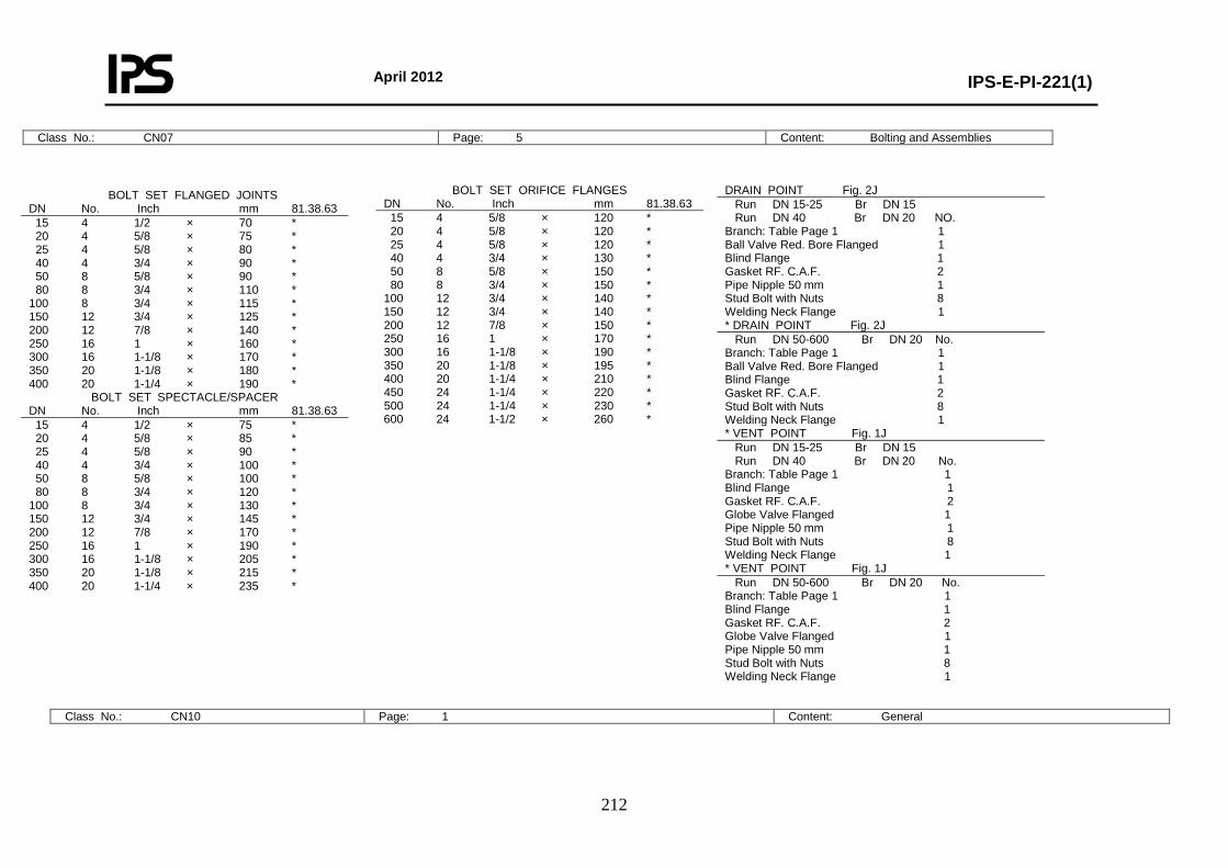
April 2012
IPS-E-PI-221(1)
212
Class No.: CN07 Page: 5 Content: Bolting and Assemblies
Class No.: CN10 Page: 1 Content: General
BOLT SET FLANGED JOINTS DN No. Inch mm 81.38.63 15 4 1/2 × 70 * 20 4 5/8 × 75 * 25 4 5/8 × 80 * 40 4 3/4 × 90 * 50 8 5/8 × 90 * 80 8 3/4 × 110 * 100 8 3/4 × 115 * 150 12 3/4 × 125 * 200 12 7/8 × 140 * 250 16 1 × 160 * 300 16 1-1/8 × 170 * 350 20 1-1/8 × 180 * 400 20 1-1/4 × 190 *
BOLT SET SPECTACLE/SPACER DN No. Inch mm 81.38.63 15 4 1/2 × 75 * 20 4 5/8 × 85 * 25 4 5/8 × 90 * 40 4 3/4 × 100 * 50 8 5/8 × 100 * 80 8 3/4 × 120 * 100 8 3/4 × 130 * 150 12 3/4 × 145 * 200 12 7/8 × 170 * 250 16 1 × 190 * 300 16 1-1/8 × 205 * 350 20 1-1/8 × 215 * 400 20 1-1/4 × 235 *
BOLT SET ORIFICE FLANGES DN No. Inch mm 81.38.63 15 4 5/8 × 120 * 20 4 5/8 × 120 * 25 4 5/8 × 120 * 40 4 3/4 × 130 * 50 8 5/8 × 150 * 80 8 3/4 × 150 * 100 12 3/4 × 140 * 150 12 3/4 × 140 * 200 12 7/8 × 150 * 250 16 1 × 170 * 300 16 1-1/8 × 190 * 350 20 1-1/8 × 195 * 400 20 1-1/4 × 210 * 450 24 1-1/4 × 220 * 500 24 1-1/4 × 230 * 600 24 1-1/2 × 260 *
DRAIN POINT Fig. 2J Run DN 15-25 Br DN 15 Run DN 40 Br DN 20 NO. Branch: Table Page 1 1 Ball Valve Red. Bore Flanged 1 Blind Flange 1 Gasket RF. C.A.F. 2 Pipe Nipple 50 mm 1 Stud Bolt with Nuts 8 Welding Neck Flange 1 * DRAIN POINT Fig. 2J Run DN 50-600 Br DN 20 No. Branch: Table Page 1 1 Ball Valve Red. Bore Flanged 1 Blind Flange 1 Gasket RF. C.A.F. 2 Stud Bolt with Nuts 8 Welding Neck Flange 1 * VENT POINT Fig. 1J Run DN 15-25 Br DN 15 Run DN 40 Br DN 20 No. Branch: Table Page 1 1 Blind Flange 1 Gasket RF. C.A.F. 2 Globe Valve Flanged 1 Pipe Nipple 50 mm 1 Stud Bolt with Nuts 8 Welding Neck Flange 1 * VENT POINT Fig. 1J Run DN 50-600 Br DN 20 No. Branch: Table Page 1 1 Blind Flange 1 Gasket RF. C.A.F. 2 Globe Valve Flanged 1 Pipe Nipple 50 mm 1 Stud Bolt with Nuts 8 Welding Neck Flange 1
April 2012
IPS-E-PI-221(1)
213
Base Material: Carbon Steel First Issue: Revision: Rating: PN 50 (Class 300) Date: Corrosion Allowance: 1 mm Sign:
Temperature °C 0 50 100 150 200 250 300 350 400 urePress Barg.
DN 15-600 42.9 42.9 42.9 42.9 42.9 40.9
38.0 36.2 27.7
Notes:
-Design limits are acc. flange rating ANSI B16.5 Material Group 1.1 and to allowable internal prisor acc. ANSI BS 31.1. - Max. allowable pressure for steam traps: 28 bar ga. - Piston type check valves for horizontal mounting only
Class No.: CN10 Page: 2 Content: Material Descriptions
TABLE OF SCHEDULES BRANCH CONNECTIONS 90 DEGREES BRANCH SIZE
Run Size 15 20 25 40 50 80 100 150 200 250 300 350 400 450 500 600
DN Schedule
15 20 25 40 50 80
100 150 200 250 300 350 400 450 500 600
80 80 80 80 40 40 40 40 30 30 30 30 30 30 30 30
600 C C C C E E E E E E E E E E E A 500 C C C C E E E E E E E E E E A 450 C C C C E E E E E E E E E A 400 C C C C E E E E E E E E A 350 C C C C E E E E E E E A 300 C C C C E E E E E E A 250 C C C C E E E E E A 200 C C C C E E E E A 150 C C C C E E E A 100 C C C C D D A 80 C C C C D A 50 C C C B A 40 C B B A 25 B B A 20 B A 15 A
CODE EXPLANATION OF CHARACTERS A Equal tee B Reducing tee C Branch fitting outlet socket weld D Pipe to pipe E Branch outlet reducing butt-weld
April 2012
IPS-E-PI-221(1)
214
* PIPE PIPE Pipe API 5L-B DN 15-400 API 5L-B (Seamless) API 5L-B DN 450-600 API 5L-B (Welded) Pipe DN 15-600 ASTM A106-B PNPP Pipe Nipple 50 mm DN 15-40 ASTM A106-B * FLANGES BLFL Blind Flange DN 15-600 ASTM A105 SBFL Spectacle Blind Flange DN 15-400 ASTM A516-60 SPRT Spacer Ring Type (ANS Flanges) DN 15-400 ASTM A516-60 WNFL Welding Neck Flange DN 15-600 ASTM A105 * FITTINGS CAPB Cap Butt-Weld. End DN 15-600 ASTM A234-WPB E45B Elbow 45 Deg. Butt-Weld. End DN 15-600 ASTM A234-WPB E90B Elbow 90 Deg. Butt-Weld. End DN 15-600 ASTM A234-WPB TEEB Equal Tee Butt-Weld. End DN 15-600 ASTM A234-WPB E45S Elbow 45 Deg. Socket-Weld. End DN 15-40 ASTM A105 E90S Elbow 90 Deg. Socket-Weld. End DN 15-40 ASTM A105 TEES Equal Tee Socket-Weld. End DN 15-40 ASTM A105 COUS Coupling Socket-Weld. End DN 15-40 ASTM A105 CAPS Cap Socket-Weld. End DN 15-40 ASTM A105 * REDUCING FITTINGS BROS Branch Fitting Outlet Socket Weld. End DN 15-40 ASTM A105 BROB Branch Outlet Red. Butt-Weld. DN 50-600 ASTM A105 RECB Reducer Conc. Butt-Weld. End DN 20-600 ASTM A234-WPB REEB Reducer Ecc. Butt-Weld. End DN 20-600 ASTM A234-WPB TERB Tee Reducing Butt-Weld. End DN 20-600 ASTM A234-WPB TERS Tee Reducing Socket-Weld. End DN 20-600 ASTM A105 Note: - For full material description see relevant MESC buying description. - Where both socket weld and butt weld fittings are specified, preference is subject to company approval. - Where both API 5L and ASTM A 106 pipes are specified, preference is subject to company approval.
* VALVES CHVF Check Valve Flanged DN 15-600 Body: ASTM A216-WCB/WCC, A105 Trim: Body Mat., AISI 316, 316L, AISI 410, + Stellite-6 CHVS Check Valve Socket DN 15-40 Body: ASTM A216-WCB/WCC, A105 Trim: Body Mat., AISI 316, 316L, AISI 410, + Stellite-6 GAVB Gate Valve Butt-Weld. End DN 50-600 Body: ASTM A216-WCB/WCC, A105 Trim: Body Mat., AISI 316, 316L, AISI 410, + Stellite-6 GAVF Gate Valve Flanged DN --- Body: ASTM A216-WCB/WCC, A105 Trim: Body Mat., AISI 316, 316L, AISI 410, + Stellite-6 GAVS Gate Valve Sw DN 15-40 Body: ASTM A216-WCB/WCC, A105 Trim: Body Mat., AISI 316, 316L, AISI 410, + Stellite-6 GLVB Globe Valve Butt-Weld. End DN 50-200 Body: ASTM A216-WCB/WCC, A105 Trim: Body Mat., AISI 316, 316L, AISI 410, + Stellite-6 GLVS Globe Valve Socket DN 15-40 Body: ASTM A216-WCB/WCC, A105 Trim: Body Mat., AISI 316, 316L, AISI 410, + Stellite-6 * MISCELLANEOUS GKSW Gasket, Spiral Wound DN 15-600 AISI 316, 316L, Asbestos Filled CS Centring Ring. ORFS Orifice Flange Set DN 50-600 ASTM A105 STBT Stud Bolt with Nuts ---- Studs: ASTM A193-B7 Nuts: ASTM A194-2H
April 2012
IPS-E-PI-221(1)
215
Class No.: CN10 Page: 3 Content: Piping Components
NOMINAL PIPE SIZE ITEM DESCRIPTION MESC 15 20 25 40 50 80 100 150 200 250 300 350 400 450 500 600
* PIPE Pipe 74.13.23/31 * * * * * * * * * * * * * 74.13.23/24 * * * 74.30.21/31 * * * * * * * * * * * * * * * * * FLANGES Blind Flange 76.62.10 * * * * * * * * * * * * * * * * Spectacle Blind Flange 76.88.06 * * * * * * * * * * * * * * * * Spacer Ring Type (ANS Flanges) 76.88.10 * * * * * * * * * * * * * * * * Welding Neck Flange 76.62.78 * * * * * * * * * * * * * * * * * FITTINGS Cap Butt-Weld. End 76.30.18 * * * * * * * * * * * * * * * * Elbow 45 Deg. Butt-Weld. End 76.30.38 * * * * * * * * * * * * * * * * Elbow 90 Deg. Butt-Weld. End 76.30.40 * * * * * * * * * * * * * * * * Equal Tee Butt-Weld. End 76.30.84 * * * * * * * * * * * * * * * * Elbow 45 Deg. Socket-Weld. End 76.34.38 * * * * Elbow 90 Deg. Socket-Weld. End 76.34.39 * * * * Equal Tee Socket-Weld. End 76.34.80 * * * * Coupling Socket-Weld. End 76.34.28 * * * * Cap Socket-Weld. End 76.34.18 * * * * * VALVES Check Valve Flanged 75.37.13 * * * * * * * * * * * * * * * * Check Valve Socket 75.56.13 * * * * Gate Valve Butt-Weld. End 75.56.33 * * * * * * * * * Gate Valve SW 75.56.35 * * * * Globe Valve Butt-Weld. End 75.56.54 * * * * * Globe Valve Socket 75.56.45 * * * * * MISCELLANEOUS Gasket, Spiral Wound 85.41.35 * * * * * * * * * * * * * * * * Orifice Flange Set 60.88.52 * * * * * * * * * * * *
April 2012
IPS-E-PI-221(1)
216
Class No.: CN10 Page: 4 Content: Reducing Piping Components
BROB RECB REEB TERB TERS Run Br. 76.80.05 76.30.72 76.30.73 76.30.85 76.34.85
BROB RECB REEB TERB Run Br. 76.80.05 76.30.72 76.30.73 76.30.85
COMP. NAME DESCRIPTION
20 × 15 * * * * 25 × 15 * * * * 25 × 20 * * * * 40 × 15 * * 40 × 20 * * * * 40 × 25 * * * * 50 × 25 * * 50 × 40 * * 80 × 40 * * 80 × 50 * * * * 100 × 50 * * * * 100 × 80 * * * * 150 × 50 * 150 × 80 * * * * 150 × 100 * * * * 200 × 50 * 200 × 80 * 200 × 100 * * * * 200 × 150 * * * * 250 × 50 * 250 × 80 * 250 × 100 * * 250 × 150 * * * * 250 × 200 * * * * 300 × 50 * 300 × 80 * 300 × 100 * 300 × 150 * * * * 300 × 200 * * * * 300 × 250 * * * * 350 × 50 * 350 × 80 * 350 × 100 * 350 × 150 * * 350 × 200 * * * * 350 × 250 * * * * 350 × 300 * * * *
400 × 50 * 400 × 80 * 400 × 100 * 400 × 150 * 400 × 200 * * * * 400 × 250 * * * * 400 × 300 * * * * 400 × 350 * * * * 450 × 80 * 450 × 100 * 450 × 150 * 450 × 200 * * * * 450 × 250 * * * * 450 × 300 * * * * 450 × 350 * * * * 450 × 400 * * * * 500 × 50 * 500 × 80 * 500 × 100 * 500 × 150 * 500 × 200 * 500 × 250 * * * * 500 × 300 * * * * 500 × 350 * * * * 500 × 400 * * * * 500 × 450 * * * * 600 × 50 * 600 × 80 * 600 × 100 * 600 × 150 * 600 × 200 * 600 × 250 * * * * 600 × 300 * * * * 600 × 350 * * * * 600 × 400 * * * * 600 × 450 * * * * 600 × 500 * * * *
BROS Branch Fitting Outlet Socket Weld BROB Branch Outlet Red. Butt-Weld RECB Reducer Conc. Butt-Weld. End REEB Reducer Ecc. Butt-Weld. End TERB Tee Reducing Butt-Weld. End TERS Tee Reducing Socket-Weld. End BROS Br. Run-Pipe 76.80.26 ------------------------------------------------------------------------------------------ 15 40-150 * 200-600 * 20 50-80 * 100-600 * 25 50 * 80-100 * 150-600 * 40 80-100 * 150-300 * 350-600 *
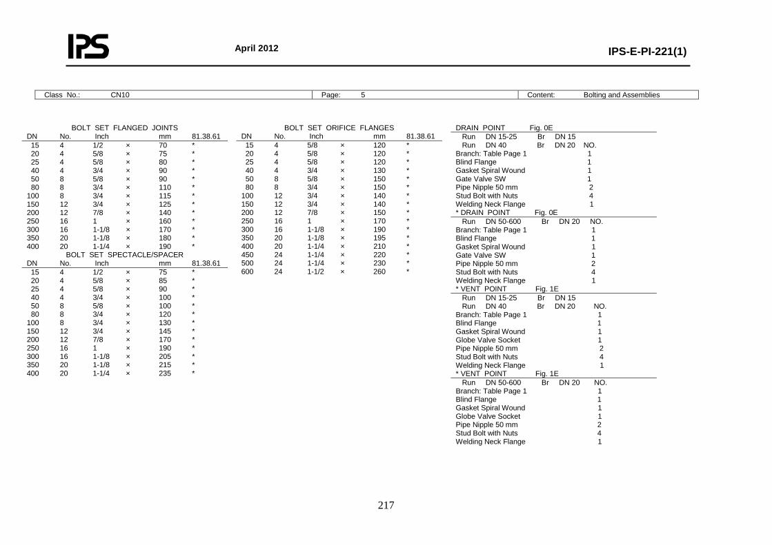
April 2012
IPS-E-PI-221(1)
217
Class No.: CN10 Page: 5 Content: Bolting and Assemblies
BOLT SET FLANGED JOINTS DN No. Inch mm 81.38.61 15 4 1/2 × 70 * 20 4 5/8 × 75 * 25 4 5/8 × 80 * 40 4 3/4 × 90 * 50 8 5/8 × 90 * 80 8 3/4 × 110 * 100 8 3/4 × 115 * 150 12 3/4 × 125 * 200 12 7/8 × 140 * 250 16 1 × 160 * 300 16 1-1/8 × 170 * 350 20 1-1/8 × 180 * 400 20 1-1/4 × 190 *
BOLT SET SPECTACLE/SPACER DN No. Inch mm 81.38.61 15 4 1/2 × 75 * 20 4 5/8 × 85 * 25 4 5/8 × 90 * 40 4 3/4 × 100 * 50 8 5/8 × 100 * 80 8 3/4 × 120 * 100 8 3/4 × 130 * 150 12 3/4 × 145 * 200 12 7/8 × 170 * 250 16 1 × 190 * 300 16 1-1/8 × 205 * 350 20 1-1/8 × 215 * 400 20 1-1/4 × 235 *
BOLT SET ORIFICE FLANGES DN No. Inch mm 81.38.61 15 4 5/8 × 120 * 20 4 5/8 × 120 * 25 4 5/8 × 120 * 40 4 3/4 × 130 * 50 8 5/8 × 150 * 80 8 3/4 × 150 * 100 12 3/4 × 140 * 150 12 3/4 × 140 * 200 12 7/8 × 150 * 250 16 1 × 170 * 300 16 1-1/8 × 190 * 350 20 1-1/8 × 195 * 400 20 1-1/4 × 210 * 450 24 1-1/4 × 220 * 500 24 1-1/4 × 230 * 600 24 1-1/2 × 260 *
DRAIN POINT Fig. 0E Run DN 15-25 Br DN 15 Run DN 40 Br DN 20 NO. Branch: Table Page 1 1 Blind Flange 1 Gasket Spiral Wound 1 Gate Valve SW 1 Pipe Nipple 50 mm 2 Stud Bolt with Nuts 4 Welding Neck Flange 1 * DRAIN POINT Fig. 0E Run DN 50-600 Br DN 20 NO. Branch: Table Page 1 1 Blind Flange 1 Gasket Spiral Wound 1 Gate Valve SW 1 Pipe Nipple 50 mm 2 Stud Bolt with Nuts 4 Welding Neck Flange 1 * VENT POINT Fig. 1E Run DN 15-25 Br DN 15 Run DN 40 Br DN 20 NO. Branch: Table Page 1 1 Blind Flange 1 Gasket Spiral Wound 1 Globe Valve Socket 1 Pipe Nipple 50 mm 2 Stud Bolt with Nuts 4 Welding Neck Flange 1 * VENT POINT Fig. 1E Run DN 50-600 Br DN 20 NO. Branch: Table Page 1 1 Blind Flange 1 Gasket Spiral Wound 1 Globe Valve Socket 1 Pipe Nipple 50 mm 2 Stud Bolt with Nuts 4 Welding Neck Flange 1
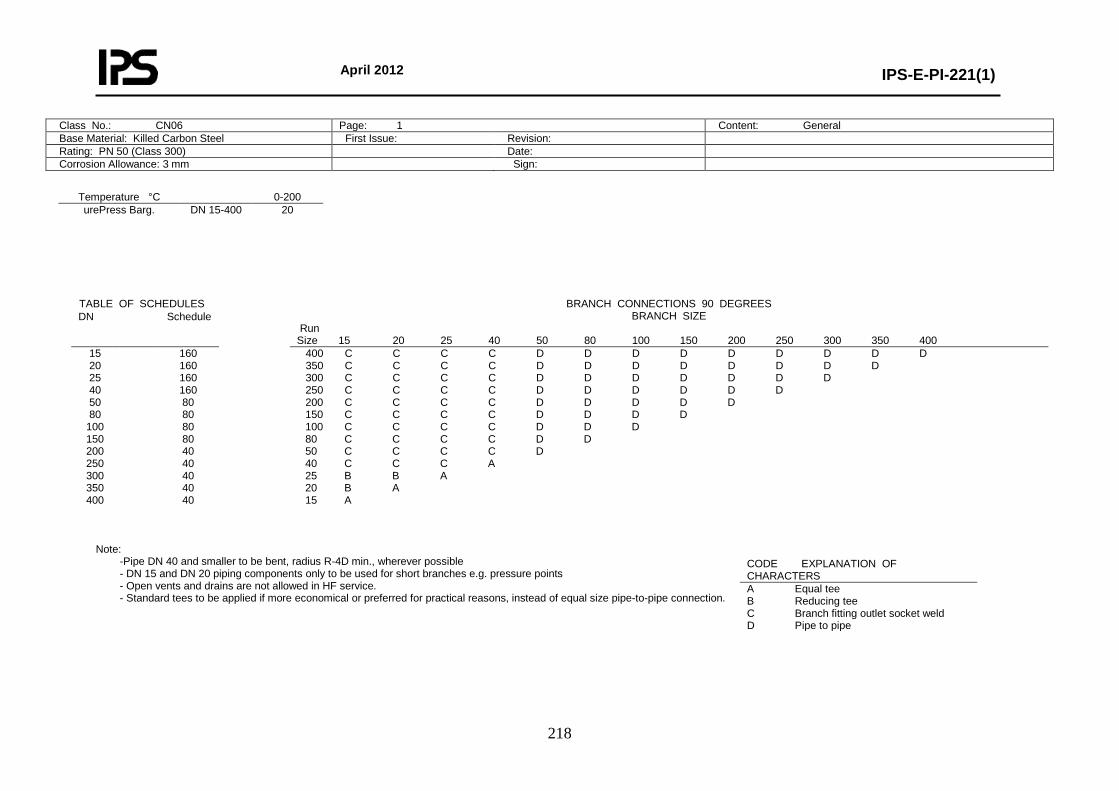
April 2012
IPS-E-PI-221(1)
218
Class No.: CN06 Page: 1 Content: General Base Material: Killed Carbon Steel First Issue: Revision: Rating: PN 50 (Class 300) Date: Corrosion Allowance: 3 mm Sign:
Temperature °C 0-200 urePress Barg.
DN 15-400 20
Note:
-Pipe DN 40 and smaller to be bent, radius R-4D min., wherever possible - DN 15 and DN 20 piping components only to be used for short branches e.g. pressure points - Open vents and drains are not allowed in HF service. - Standard tees to be applied if more economical or preferred for practical reasons, instead of equal size pipe-to-pipe connection.
TABLE OF SCHEDULES BRANCH CONNECTIONS 90 DEGREES BRANCH SIZE
Run Size 15 20 25 40 50 80 100 150 200 250 300 350 400
DN Schedule
15 20 25 40 50 80
100 150 200 250 300 350 400
160 160 160 160 80 80 80 80 40 40 40 40 40
400 C C C C D D D D D D D D D 350 C C C C D D D D D D D D 300 C C C C D D D D D D D 250 C C C C D D D D D D 200 C C C C D D D D D 150 C C C C D D D D 100 C C C C D D D 80 C C C C D D 50 C C C C D 40 C C C A 25 B B A 20 B A 15 A
CODE EXPLANATION OF CHARACTERS A Equal tee B Reducing tee C Branch fitting outlet socket weld D Pipe to pipe
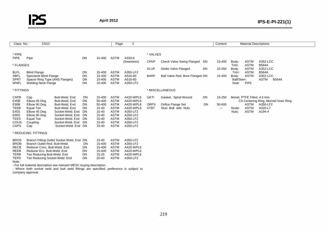
April 2012
IPS-E-PI-221(1)
219
Class No.: CN12 Page: 2 Content: Material Descriptions
* PIPE PIPE Pipe DN 15-400 ASTM A333-6 (Seamless) * FLANGES BLFL Blind Flange DN 15-400 ASTM A350-LF2 SBFL Spectacle Blind Flange DN 15-400 ASTM A516-60 SPRT Spacer Ring Type (ANS Flanges) DN 15-400 ASTM A516-60 WNFL Welding Neck Flange DN 15-400 ASTM A350-LF2 * FITTINGS CAPB Cap Butt-Weld. End DN 15-400 ASTM A420-WPL6 E45B Elbow 45 Deg. Butt-Weld. End DN 50-400 ASTM A420-WPL6 E90B Elbow 90 Deg. Butt-Weld. End DN 50-400 ASTM A420-WPL6 TEEB Equal Tee Butt-Weld. End DN 15-40 ASTM A420-WPL6 E45S Elbow 45 Deg. Socket-Weld. End DN 15-40 ASTM A350-LF2 E90S Elbow 90 Deg. Socket-Weld. End DN 15-40 ASTM A350-LF2 TEES Equal Tee Socket-Weld. End DN 15-40 ASTM A350-LF2 COUS Coupling Socket-Weld. End DN 15-40 ASTM A350-LF2 CAPS Cap Socket-Weld. End DN 15-40 ASTM A350-LF2 * REDUCING FITTINGS BROS Branch Fitting Outlet Socket Weld. End DN 15-40 ASTM A350-LF2 BROB Branch Outlet Red. Butt-Weld. DN 15-400 ASTM A350-LF2 RECB Reducer Conc. Butt-Weld. End DN 15-400 ASTM A420-WPL6 REEB Reducer Ecc. Butt-Weld. End DN 15-400 ASTM A420-WPL6 TERB Tee Reducing Butt-Weld. End DN 15-25 ASTM A420-WPL6 TERS Tee Reducing Socket-Weld. End DN 20-40 ASTM A350-LF2 Note: - For full material description see relevant MESC buying description. - Where both socket weld and butt weld fittings are specified, preference is subject to company approval.
* VALVES CHVF Check Valve Swing Flanged DN 15-400 Body: ASTM A352-LCC Trim: ASTM B564A GLVF Globe Valve Flanged DN 15-250 Body: ASTM A352-LCC Trim: ASTM B564A BARF Ball Valve Red. Bore Flanged DN 15-400 Body: ASTM A352-LCC Ball/Stem: ASTM B564A Seat: PIFE * MISCELLANEOUS GKTI Gasket, Spiral Wound DN 15-250 Monel, PTFE Filled, 4.5 mm CS Centering Ring, Monnel Inner Ring ORFS Orifice Flange Set DN 50-600 ASTM A350-LF2 STBT Stud Bolt with Nuts --- Studs: ASTM A320-L7 Nuts: ASTM A194-4
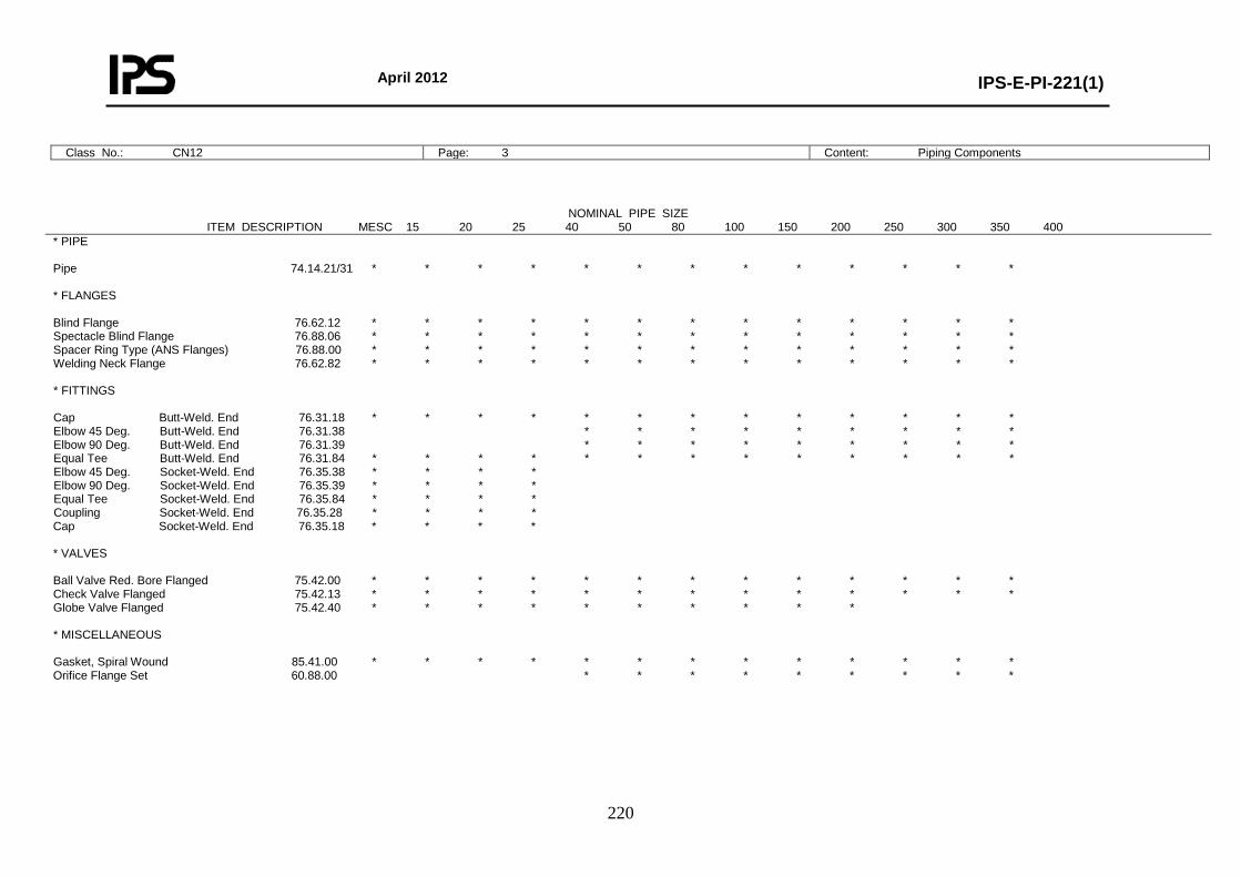
April 2012
IPS-E-PI-221(1)
220
Class No.: CN12 Page: 3 Content: Piping Components
NOMINAL PIPE SIZE ITEM DESCRIPTION MESC 15 20 25 40 50 80 100 150 200 250 300 350 400
* PIPE Pipe 74.14.21/31 * * * * * * * * * * * * * * FLANGES Blind Flange 76.62.12 * * * * * * * * * * * * * Spectacle Blind Flange 76.88.06 * * * * * * * * * * * * * Spacer Ring Type (ANS Flanges) 76.88.00 * * * * * * * * * * * * * Welding Neck Flange 76.62.82 * * * * * * * * * * * * * * FITTINGS Cap Butt-Weld. End 76.31.18 * * * * * * * * * * * * * Elbow 45 Deg. Butt-Weld. End 76.31.38 * * * * * * * * * Elbow 90 Deg. Butt-Weld. End 76.31.39 * * * * * * * * * Equal Tee Butt-Weld. End 76.31.84 * * * * * * * * * * * * * Elbow 45 Deg. Socket-Weld. End 76.35.38 * * * * Elbow 90 Deg. Socket-Weld. End 76.35.39 * * * * Equal Tee Socket-Weld. End 76.35.84 * * * * Coupling Socket-Weld. End 76.35.28 * * * * Cap Socket-Weld. End 76.35.18 * * * * * VALVES Ball Valve Red. Bore Flanged 75.42.00 * * * * * * * * * * * * * Check Valve Flanged 75.42.13 * * * * * * * * * * * * * Globe Valve Flanged 75.42.40 * * * * * * * * * * * MISCELLANEOUS Gasket, Spiral Wound 85.41.00 * * * * * * * * * * * * * Orifice Flange Set 60.88.00 * * * * * * * * *
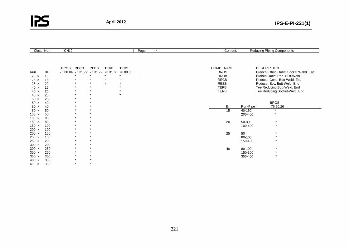
April 2012
IPS-E-PI-221(1)
221
Class No.: CN12 Page: 4 Content: Reducing Piping Components
BROB RECB REEB TERB TERS Run Br. 76.80.04 76.31.72 76.31.72 76.31.85 76.00.85 20 × 15 * * * * 25 × 15 * * * * 25 × 20 * * * * 40 × 15 * * * 40 × 20 * * * 40 × 25 * * * 50 × 25 * * 50 × 40 * * 80 × 40 * * 80 × 50 * * 100 × 50 * * 100 × 80 * * 150 × 80 * * 150 × 100 * * 200 × 100 * * 200 × 150 * * 250 × 150 * * 250 × 200 * * 300 × 200 * * 300 × 250 * * 350 × 250 * * 350 × 300 * * 400 × 300 * * 400 × 350 * *
COMP. NAME DESCRIPTION BROS Branch Fitting Outlet Socket Wekd. End BROB Branch Outlet Red. Butt-Weld RECB Reducer Conc. Butt-Weld. End REEB Reducer Ecc. Butt-Weld. End TERB Tee Reducing Butt-Weld. End TERS Tee Reducing Socket-Weld. End BROS Br. Run-Pipe 76.80.26 15 40-150 * 200-400 * 20 50-80 * 100-400 * 25 50 * 80-100 * 150-400 * 40 80-100 * 150-300 * 350-400 *
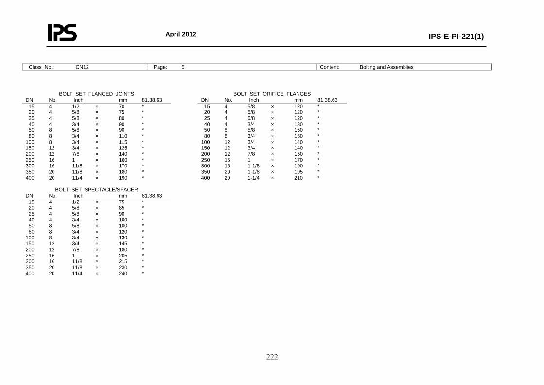
April 2012
IPS-E-PI-221(1)
222
Class No.: CN12 Page: 5 Content: Bolting and Assemblies
BOLT SET FLANGED JOINTS DN No. Inch mm 81.38.63 15 4 1/2 × 70 * 20 4 5/8 × 75 * 25 4 5/8 × 80 * 40 4 3/4 × 90 * 50 8 5/8 × 90 * 80 8 3/4 × 110 * 100 8 3/4 × 115 * 150 12 3/4 × 125 * 200 12 7/8 × 140 * 250 16 1 × 160 * 300 16 11/8 × 170 * 350 20 11/8 × 180 * 400 20 11/4 × 190 *
BOLT SET SPECTACLE/SPACER DN No. Inch mm 81.38.63 15 4 1/2 × 75 * 20 4 5/8 × 85 * 25 4 5/8 × 90 * 40 4 3/4 × 100 * 50 8 5/8 × 100 * 80 8 3/4 × 120 * 100 8 3/4 × 130 * 150 12 3/4 × 145 * 200 12 7/8 × 180 * 250 16 1 × 205 * 300 16 11/8 × 215 * 350 20 11/8 × 230 * 400 20 11/4 × 240 *
BOLT SET ORIFICE FLANGES DN No. Inch mm 81.38.63 15 4 5/8 × 120 * 20 4 5/8 × 120 * 25 4 5/8 × 120 * 40 4 3/4 × 130 * 50 8 5/8 × 150 * 80 8 3/4 × 150 * 100 12 3/4 × 140 * 150 12 3/4 × 140 * 200 12 7/8 × 150 * 250 16 1 × 170 * 300 16 1-1/8 × 190 * 350 20 1-1/8 × 195 * 400 20 1-1/4 × 210 *
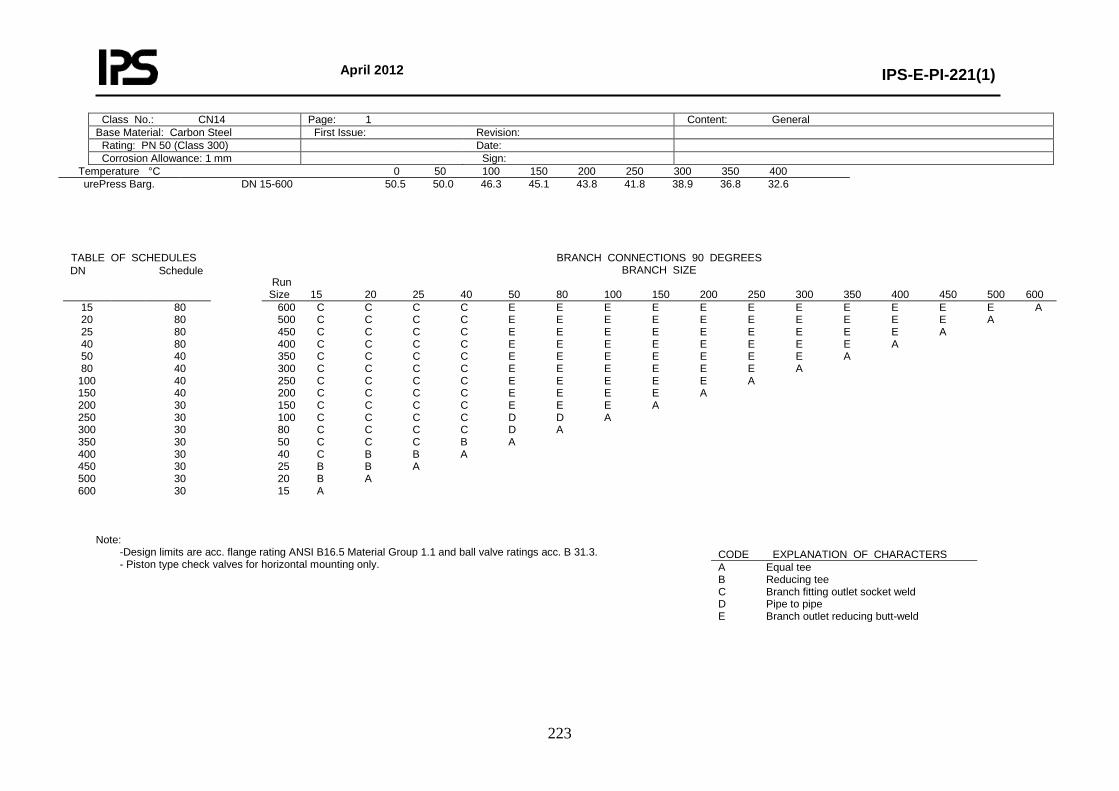
April 2012
IPS-E-PI-221(1)
223
Temperature °C 0 50 100 150 200 250 300 350 400 urePress Barg.
DN 15-600 50.5 50.0 46.3 45.1 43.8 41.8 38.9 36.8 32.6
Note:
-Design limits are acc. flange rating ANSI B16.5 Material Group 1.1 and ball valve ratings acc. B 31.3. - Piston type check valves for horizontal mounting only.
Class No.: CN14 Page: 1 Content: General Base Material: Carbon Steel First Issue: Revision: Rating: PN 50 (Class 300) Date: Corrosion Allowance: 1 mm Sign:
TABLE OF SCHEDULES BRANCH CONNECTIONS 90 DEGREES BRANCH SIZE
Run Size 15 20 25 40 50 80 100 150 200 250 300 350 400 450 500 600
DN Schedule
15 20 25 40 50 80
100 150 200 250 300 350 400 450 500 600
80 80 80 80 40 40 40 40 30 30 30 30 30 30 30 30
600 C C C C E E E E E E E E E E E A 500 C C C C E E E E E E E E E E A 450 C C C C E E E E E E E E E A 400 C C C C E E E E E E E E A 350 C C C C E E E E E E E A 300 C C C C E E E E E E A 250 C C C C E E E E E A 200 C C C C E E E E A 150 C C C C E E E A 100 C C C C D D A 80 C C C C D A 50 C C C B A 40 C B B A 25 B B A 20 B A 15 A
CODE EXPLANATION OF CHARACTERS A Equal tee B Reducing tee C Branch fitting outlet socket weld D Pipe to pipe E Branch outlet reducing butt-weld

April 2012
IPS-E-PI-221(1)
224
Class No.: CN14 Page: 2 Content: Material Descriptions
* PIPE PIPE Pipe DN 15-600 ASTM A106-B PNPP Pipe Nipple 50 mm DN 15-40 ASTM A106-B * FLANGES BLFL Blind Flange DN 15-600 ASTM A105 SBFL Spectacle Blind Flange DN 15-600 ASTM A516-60 SPRT Spacer Ring Type (ANS Flanges) DN 15-600 ASTM A516-60 WNFL Welding Neck Flange DN 15-600 ASTM A105 * FITTINGS CAPB Cap Butt-Weld. End DN 15-600 ASTM A234-WPB E45B Elbow 45 Deg. Butt-Weld. End DN 15-600 ASTM A234-WPB E90B Elbow 90 Deg. Butt-Weld. End DN 15-600 ASTM A234-WPB TEEB Equal Tee Butt-Weld. End DN 15-600 ASTM A234-WPB E45S Elbow 45 Deg. Socket-Weld. End DN 15-40 ASTM A105 E90S Elbow 90 Deg. Socket-Weld. End DN 15-40 ASTM A105 TEES Equal Tee Socket-Weld. End DN 15-40 ASTM A105 COUS Coupling Socket-Weld. End DN 15-40 ASTM A105 CAPS Cap Socket-Weld. End DN 15-40 ASTM A105 * REDUCING FITTINGS BROS Branch Fitting Outlet Socket Weld. End DN 15-40 ASTM A105 BROB Branch Outlet Red. Butt-Weld . DN 50-600 ASTM A105 RECB Reducer Conc. Butt-Weld. End DN 20-600 ASTM A234-WPB REEB Reducer Ecc. Butt-Weld. End DN 20-600 ASTM A234-WPB TERB Tee Reducing Butt-Weld. End DN 20-600 ASTM A234-WPB TERS Tee Reducing Socket-Weld. End DN 20-40 ASTM A105 Note: - For full material description see relevant MESC buying description. - Where both socket weld and butt weld fittings are specified, preference is subject to company approval.
* VALVES CHVF Check Valve Flanged DN 15-600 Body: ASTM A216-WCB/WCC, A105 Trim: AISI 410 GAVF Gate Valve Flanged DN 15-600 Body: ASTM A216-WCB/WCC, A105 Trim: AISI 410 GLVF Globe Valve Flanged DN 15-200 Body: ASTM A216-WCB/WCC, A105 Trim: AISI 410 * MISCELLANEOUS GKSW Gasket, Spiral Wound DN 15-600 AISI 316, Graphite Filled, CS Centring-, SS Inner Ring ORFS Orifice Flange Set DN 50-600 ASTM A105 STBT Stud Bolt with Nuts --- Studs: ASTM A193-B7 Nuts: ASTM A194-2H
Class No.: CN14 Page: 3 Content: Piping Components
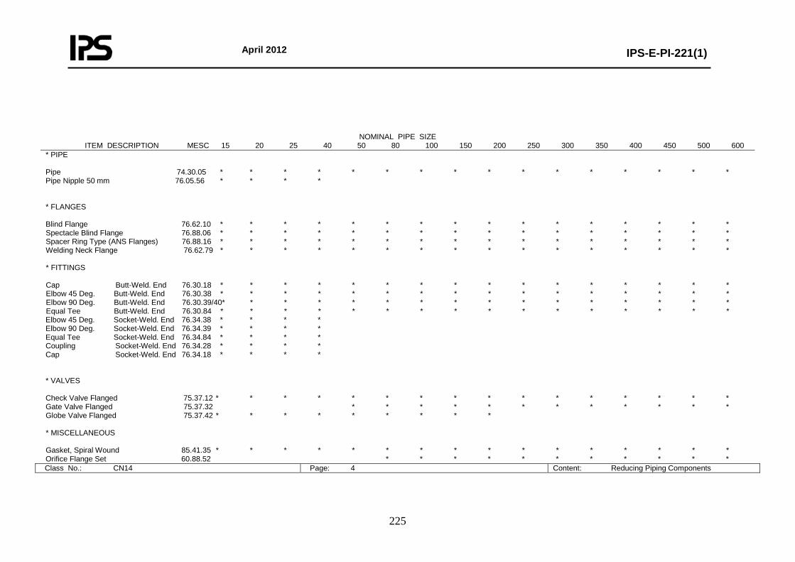
April 2012
IPS-E-PI-221(1)
225
Class No.: CN14 Page: 4 Content: Reducing Piping Components
NOMINAL PIPE SIZE ITEM DESCRIPTION MESC 15 20 25 40 50 80 100 150 200 250 300 350 400 450 500 600
* PIPE Pipe 74.30.05 * * * * * * * * * * * * * * * * Pipe Nipple 50 mm 76.05.56 * * * * * FLANGES Blind Flange 76.62.10 * * * * * * * * * * * * * * * * Spectacle Blind Flange 76.88.06 * * * * * * * * * * * * * * * * Spacer Ring Type (ANS Flanges) 76.88.16 * * * * * * * * * * * * * * * * Welding Neck Flange 76.62.79 * * * * * * * * * * * * * * * * * FITTINGS Cap Butt-Weld. End 76.30.18 * * * * * * * * * * * * * * * * Elbow 45 Deg. Butt-Weld. End 76.30.38 * * * * * * * * * * * * * * * * Elbow 90 Deg. Butt-Weld. End 76.30.39/40* * * * * * * * * * * * * * * * Equal Tee Butt-Weld. End 76.30.84 * * * * * * * * * * * * * * * * Elbow 45 Deg. Socket-Weld. End 76.34.38 * * * * Elbow 90 Deg. Socket-Weld. End 76.34.39 * * * * Equal Tee Socket-Weld. End 76.34.84 * * * * Coupling Socket-Weld. End 76.34.28 * * * * Cap Socket-Weld. End 76.34.18 * * * * * VALVES Check Valve Flanged 75.37.12 * * * * * * * * * * * * * * * * Gate Valve Flanged 75.37.32 * * * * * * * * * * * * Globe Valve Flanged 75.37.42 * * * * * * * * * * MISCELLANEOUS Gasket, Spiral Wound 85.41.35 * * * * * * * * * * * * * * * * Orifice Flange Set 60.88.52 * * * * * * * * * * *
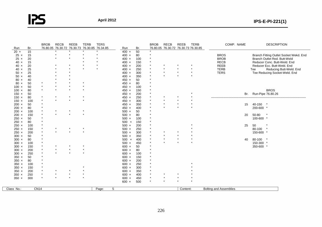
April 2012
IPS-E-PI-221(1)
226
Class No.: CN14 Page: 5 Content: Bolting and Assemblies
BROB RECB REEB TERB TERS Run Br. 76.80.05 76.30.72 76.30.73 76.30.85 76.34.85
BROB RECB REEB TERB Run Br. 76.80.05 76.30.72 76.30.73 76.30.85
COMP. NAME DESCRIPTION
20 × 15 * * * * 25 × 15 * * * * 25 × 20 * * * * 40 × 15 * * 40 × 20 * * * * 40 × 25 * * * * 50 × 25 * * 50 × 40 * * 80 × 40 * * 80 × 50 * * * * 100 × 50 * * * * 100 × 80 * * * * 150 × 50 150 × 80 * * * * 150 × 100 * * * * 200 × 50 * 200 × 80 * 200 × 100 * * * * 200 × 150 * * * * 250 × 50 * 250 × 80 * 250 × 100 * 250 × 150 * * * * 250 × 200 * * * * 300 × 50 * 300 × 80 * 300 × 100 * 300 × 150 * * * * 300 × 200 * * * * 300 × 250 * * * * 350 × 50 * 350 × 80 * 350 × 100 * 350 × 150 * * 350 × 200 * * * * 350 × 250 * * * * 350 × 300 * * * *
400 × 50 * 400 × 80 * 400 × 100 * 400 × 150 * 400 × 200 * * * * 400 × 250 * * * * 400 × 300 * * * * 400 × 350 * * * * 450 × 50 * 450 × 80 * 450 × 100 * 450 × 150 * 450 × 200 * * 450 × 250 * * * * 450 × 300 * * * * 450 × 350 * * * * 450 × 400 * * * * 500 × 50 * 500 × 80 * 500 × 100 * 500 × 150 * 500 × 200 * * 500 × 250 * * 500 × 300 * * * * 500 × 350 * * * * 500 × 400 * * * * 500 × 450 * * * * 600 × 50 * 600 × 80 * 600 × 100 * 600 × 150 * 600 × 200 * 600 × 250 * * 600 × 300 * * 600 × 350 * * 600 × 400 * * * * 600 × 450 * * * * 600 × 500 * * * *
BROS Branch Fitting Outlet Socket Wekd. End BROB Branch Outlet Red. Butt-Weld RECB Reducer Conc. Butt-Weld. End REEB Reducer Ecc. Butt-Weld. End TERB Tee Reducing Butt-Weld. End TERS Tee Reducing Socket-Weld. End BROS Br. Run-Pipe 76.80.26 --------------------------------------------------------------------------------------------- 15 40-150 * 200-600 * 20 50-80 * 100-600 * 25 50 * 80-100 * 150-600 * 40 80-100 * 150-300 * 350-600 *
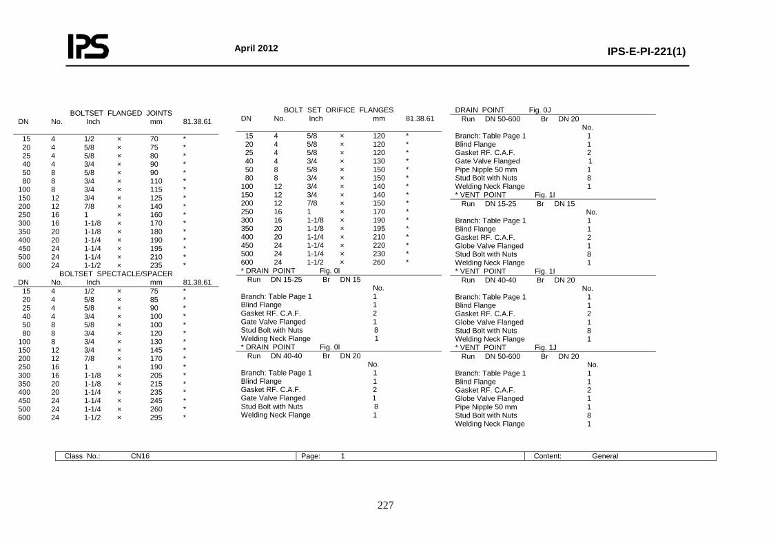
April 2012
IPS-E-PI-221(1)
227
BOLTSET FLANGED JOINTS DN No. Inch mm 81.38.61 15 4 1/2 × 70 * 20 4 5/8 × 75 * 25 4 5/8 × 80 * 40 4 3/4 × 90 * 50 8 5/8 × 90 * 80 8 3/4 × 110 * 100 8 3/4 × 115 * 150 12 3/4 × 125 * 200 12 7/8 × 140 * 250 16 1 × 160 * 300 16 1-1/8 × 170 * 350 20 1-1/8 × 180 * 400 20 1-1/4 × 190 * 450 24 1-1/4 × 195 * 500 24 1-1/4 × 210 * 600 24 1-1/2 × 235 *
BOLTSET SPECTACLE/SPACER DN No. Inch mm 81.38.61 15 4 1/2 × 75 * 20 4 5/8 × 85 * 25 4 5/8 × 90 * 40 4 3/4 × 100 * 50 8 5/8 × 100 * 80 8 3/4 × 120 * 100 8 3/4 × 130 * 150 12 3/4 × 145 * 200 12 7/8 × 170 * 250 16 1 × 190 * 300 16 1-1/8 × 205 * 350 20 1-1/8 × 215 * 400 20 1-1/4 × 235 * 450 24 1-1/4 × 245 * 500 24 1-1/4 × 260 * 600 24 1-1/2 × 295 *
BOLT SET ORIFICE FLANGES DN No. Inch mm 81.38.61 15 4 5/8 × 120 * 20 4 5/8 × 120 * 25 4 5/8 × 120 * 40 4 3/4 × 130 * 50 8 5/8 × 150 * 80 8 3/4 × 150 * 100 12 3/4 × 140 * 150 12 3/4 × 140 * 200 12 7/8 × 150 * 250 16 1 × 170 * 300 16 1-1/8 × 190 * 350 20 1-1/8 × 195 * 400 20 1-1/4 × 210 * 450 24 1-1/4 × 220 * 500 24 1-1/4 × 230 * 600 24 1-1/2 × 260 * * DRAIN POINT Fig. 0I Run DN 15-25 Br DN 15 No. Branch: Table Page 1 1 Blind Flange 1 Gasket RF. C.A.F. 2 Gate Valve Flanged 1 Stud Bolt with Nuts 8 Welding Neck Flange 1 * DRAIN POINT Fig. 0I Run DN 40-40 Br DN 20 No. Branch: Table Page 1 1 Blind Flange 1 Gasket RF. C.A.F. 2 Gate Valve Flanged 1 Stud Bolt with Nuts 8 Welding Neck Flange 1
DRAIN POINT Fig. 0J Run DN 50-600 Br DN 20 No. Branch: Table Page 1 1 Blind Flange 1 Gasket RF. C.A.F. 2 Gate Valve Flanged 1 Pipe Nipple 50 mm 1 Stud Bolt with Nuts 8 Welding Neck Flange 1 * VENT POINT Fig. 1I Run DN 15-25 Br DN 15 No. Branch: Table Page 1 1 Blind Flange 1 Gasket RF. C.A.F. 2 Globe Valve Flanged 1 Stud Bolt with Nuts 8 Welding Neck Flange 1 * VENT POINT Fig. 1I Run DN 40-40 Br DN 20 No. Branch: Table Page 1 1 Blind Flange 1 Gasket RF. C.A.F. 2 Globe Valve Flanged 1 Stud Bolt with Nuts 8 Welding Neck Flange 1 * VENT POINT Fig. 1J Run DN 50-600 Br DN 20 No. Branch: Table Page 1 1 Blind Flange 1 Gasket RF. C.A.F. 2 Globe Valve Flanged 1 Pipe Nipple 50 mm 1 Stud Bolt with Nuts 8 Welding Neck Flange 1
Class No.: CN16 Page: 1 Content: General
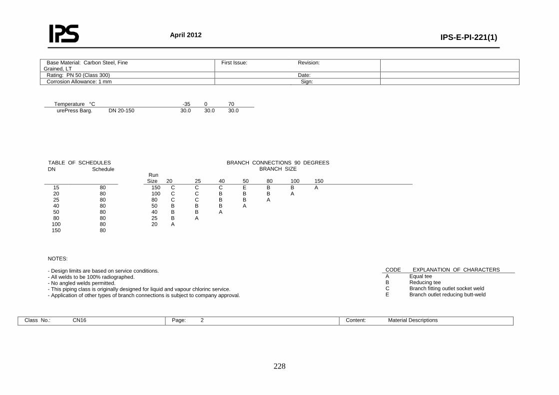
April 2012
IPS-E-PI-221(1)
228
Temperature °C -35 0 70 urePress Barg.
DN 20-150 30.0 30.0 30.0
NOTES: - Design limits are based on service conditions. - All welds to be 100% radiographed. - No angled welds permitted. - This piping class is originally designed for liquid and vapour chlorinc service. - Application of other types of branch connections is subject to company approval.
Class No.: CN16 Page: 2 Content: Material Descriptions
Base Material: Carbon Steel, Fine Grained, LT
First Issue: Revision:
Rating: PN 50 (Class 300) Date: Corrosion Allowance: 1 mm Sign:
TABLE OF SCHEDULES BRANCH CONNECTIONS 90 DEGREES BRANCH SIZE
Run Size 20 25 40 50 80 100 150
DN Schedule
15 20 25 40 50 80
100 150
80 80 80 80 80 80 80 80
150 C C C E B B A 100 C C B B B A 80 C C B B A 50 B B B A 40 B B A 25 B A 20 A
CODE EXPLANATION OF CHARACTERS A Equal tee B Reducing tee C Branch fitting outlet socket weld E Branch outlet reducing butt-weld
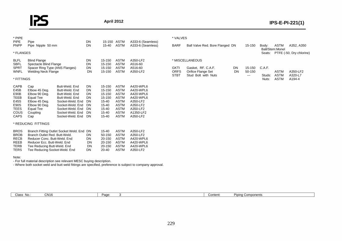
April 2012
IPS-E-PI-221(1)
229
* PIPE PIPE Pipe DN 15-150 ASTM A333-6 (Seamless) PNPP Pipe Nipple 50 mm DN 15-40 ASTM A333-6 (Seamless) * FLANGES BLFL Blind Flange DN 15-150 ASTM A350-LF2 SBFL Spectacle Blind Flange DN 15-150 ASTM A516-60 SPRT Spacer Ring Type (ANS Flanges) DN 15-150 ASTM A516-60 WNFL Welding Neck Flange DN 15-150 ASTM A350-LF2 * FITTINGS CAPB Cap Butt-Weld. End DN 15-150 ASTM A420-WPL6 E45B Elbow 45 Deg. Butt-Weld. End DN 15-150 ASTM A420-WPL6 E90B Elbow 90 Deg. Butt-Weld. End DN 15-150 ASTM A420-WPL6 TEEB Equal Tee Butt-Weld. End DN 15-150 ASTM A420-WPL6 E45S Elbow 45 Deg. Socket-Weld. End DN 15-40 ASTM A350-LF2 E90S Elbow 90 Deg. Socket-Weld. End DN 15-40 ASTM A350-LF2 TEES Equal Tee Socket-Weld. End DN 15-40 ASTM A350-LF2 COUS Coupling Socket-Weld. End DN 15-40 ASTM A1350-LF2 CAPS Cap Socket-Weld. End DN 15-40 ASTM A350-LF2 * REDUCING FITTINGS BROS Branch Fitting Outlet Socket Weld. End DN 15-40 ASTM A350-LF2 BROB Branch Outlet Red. Butt-Weld. DN 50-150 ASTM A350-LF2 RECB Reducer Conc. Butt-Weld. End DN 20-150 ASTM A420-WPL6 REEB Reducer Ecc. Butt-Weld. End DN 20-150 ASTM A420-WPL6 TERB Tee Reducing Butt-Weld. End DN 20-150 ASTM A420-WPL6 TERS Tee Reducing Socket-Weld. End DN 20-40 ASTM A350-LF2 Note: - For full material description see relevant MESC buying description. - Where both socket weld and butt weld fittings are specified, preference is subject to company approval.
* VALVES BARF Ball Valve Red. Bore Flanged DN 15-150 Body: ASTM A352, A350 Ball/Stem:Monel Seats: PTFE (-50, Dry chlorine) * MISCELLANEOUS GKTI Gasket, RF. C.A.F. DN 15-150 C.A.F. ORFS Orifice Flange Set DN 50-150 ASTM A350-LF2 STBT Stud Bolt with Nuts --- Studs: ASTM A320-L7 Nuts: ASTM A194-4
Class No.: CN16 Page: 3 Content: Piping Components
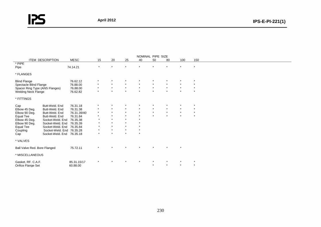
April 2012
IPS-E-PI-221(1)
230
NOMINAL PIPE SIZE ITEM DESCRIPTION MESC 15 20 25 40 50 80 100 150 * PIPE Pipe 74.14.21 * * * * * * * * * FLANGES Blind Flange 76.62.12 * * * * * * * * Spectacle Blind Flange 76.88.00 * * * * * * * * Spacer Ring Type (ANS Flanges) 76.88.00 * * * * * * * * Welding Neck Flange 76.62.82 * * * * * * * * * FITTINGS Cap Butt-Weld. End 76.31.18 * * * * * * * * Elbow 45 Deg. Butt-Weld. End 76.31.38 * * * * * * * * Elbow 90 Deg. Butt-Weld. End 76.31.39/40 * * * * * * * * Equal Tee Butt-Weld. End 76.31.84 * * * * * * * * Elbow 45 Deg. Socket-Weld. End 76.35.38 * * * * Elbow 90 Deg. Socket-Weld. End 76.35.39 * * * * Equal Tee Socket-Weld. End 76.35.84 * * * * Coupling Socket-Weld. End 76.35.28 * * * * Cap Socket-Weld. End 76.35.18 * * * * * VALVES Ball Valve Red. Bore Flanged 75.72.11 * * * * * * * * MISCELLANEOUS Gasket, RF. C.A.F. 85.31.15/17 * * * * * * * * Orifice Flange Set 60.88.00 * * * *
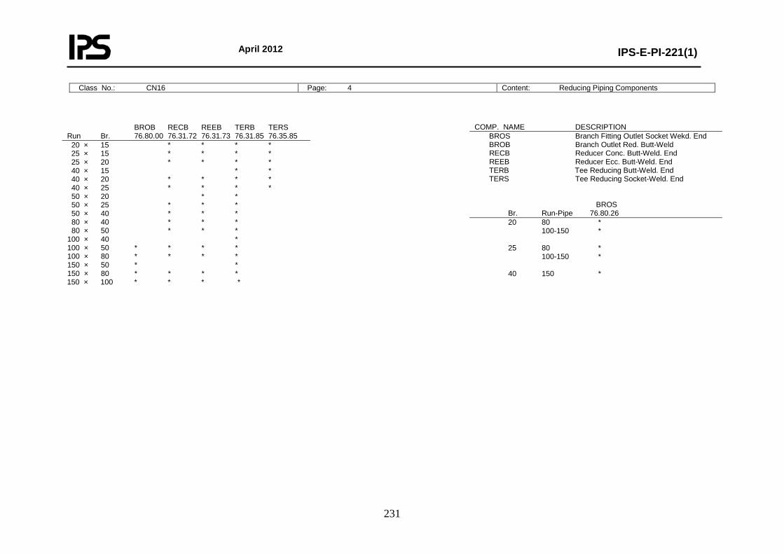
April 2012
IPS-E-PI-221(1)
231
Class No.: CN16 Page: 4 Content: Reducing Piping Components
BROB RECB REEB TERB TERS Run Br. 76.80.00 76.31.72 76.31.73 76.31.85 76.35.85 20 × 15 * * * * 25 × 15 * * * * 25 × 20 * * * * 40 × 15 * * 40 × 20 * * * * 40 × 25 * * * * 50 × 20 * * 50 × 25 * * * 50 × 40 * * * 80 × 40 * * * 80 × 50 * * * 100 × 40 * 100 × 50 * * * * 100 × 80 * * * * 150 × 50 * * 150 × 80 * * * * 150 × 100 * * * *
COMP. NAME DESCRIPTION BROS Branch Fitting Outlet Socket Wekd. End BROB Branch Outlet Red. Butt-Weld RECB Reducer Conc. Butt-Weld. End REEB Reducer Ecc. Butt-Weld. End TERB Tee Reducing Butt-Weld. End TERS Tee Reducing Socket-Weld. End BROS Br. Run-Pipe 76.80.26 20 80 * 100-150 * 25 80 * 100-150 * 40 150 *
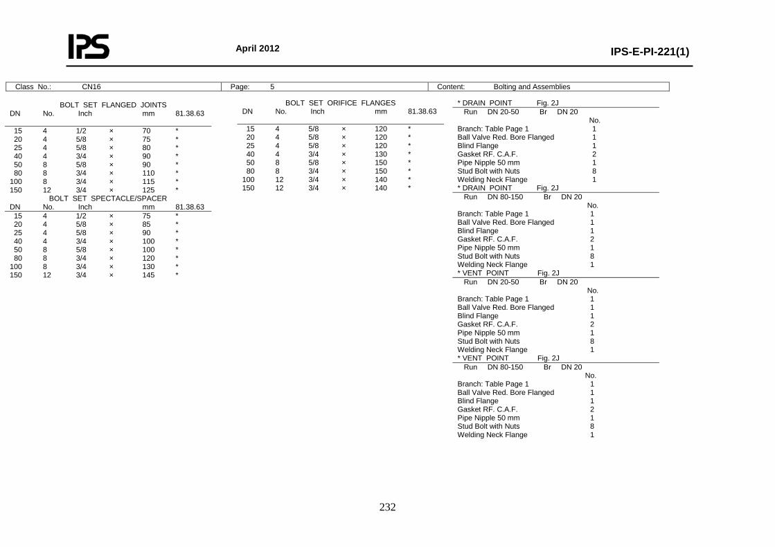
April 2012
IPS-E-PI-221(1)
232
Class No.: CN16 Page: 5 Content: Bolting and Assemblies
BOLT SET ORIFICE FLANGES DN No. Inch mm 81.38.63 15 4 5/8 × 120 * 20 4 5/8 × 120 * 25 4 5/8 × 120 * 40 4 3/4 × 130 * 50 8 5/8 × 150 * 80 8 3/4 × 150 * 100 12 3/4 × 140 * 150 12 3/4 × 140 *
* DRAIN POINT Fig. 2J Run DN 20-50 Br DN 20 No. Branch: Table Page 1 1 Ball Valve Red. Bore Flanged 1 Blind Flange 1 Gasket RF. C.A.F. 2 Pipe Nipple 50 mm 1 Stud Bolt with Nuts 8 Welding Neck Flange 1 * DRAIN POINT Fig. 2J Run DN 80-150 Br DN 20 No. Branch: Table Page 1 1 Ball Valve Red. Bore Flanged 1 Blind Flange 1 Gasket RF. C.A.F. 2 Pipe Nipple 50 mm 1 Stud Bolt with Nuts 8 Welding Neck Flange 1 * VENT POINT Fig. 2J Run DN 20-50 Br DN 20 No. Branch: Table Page 1 1 Ball Valve Red. Bore Flanged 1 Blind Flange 1 Gasket RF. C.A.F. 2 Pipe Nipple 50 mm 1 Stud Bolt with Nuts 8 Welding Neck Flange 1 * VENT POINT Fig. 2J Run DN 80-150 Br DN 20 No. Branch: Table Page 1 1 Ball Valve Red. Bore Flanged 1 Blind Flange 1 Gasket RF. C.A.F. 2 Pipe Nipple 50 mm 1 Stud Bolt with Nuts 8 Welding Neck Flange 1
BOLT SET FLANGED JOINTS DN No. Inch mm 81.38.63 15 4 1/2 × 70 * 20 4 5/8 × 75 * 25 4 5/8 × 80 * 40 4 3/4 × 90 * 50 8 5/8 × 90 * 80 8 3/4 × 110 * 100 8 3/4 × 115 * 150 12 3/4 × 125 *
BOLT SET SPECTACLE/SPACER DN No. Inch mm 81.38.63 15 4 1/2 × 75 * 20 4 5/8 × 85 * 25 4 5/8 × 90 * 40 4 3/4 × 100 * 50 8 5/8 × 100 * 80 8 3/4 × 120 * 100 8 3/4 × 130 * 150 12 3/4 × 145 *
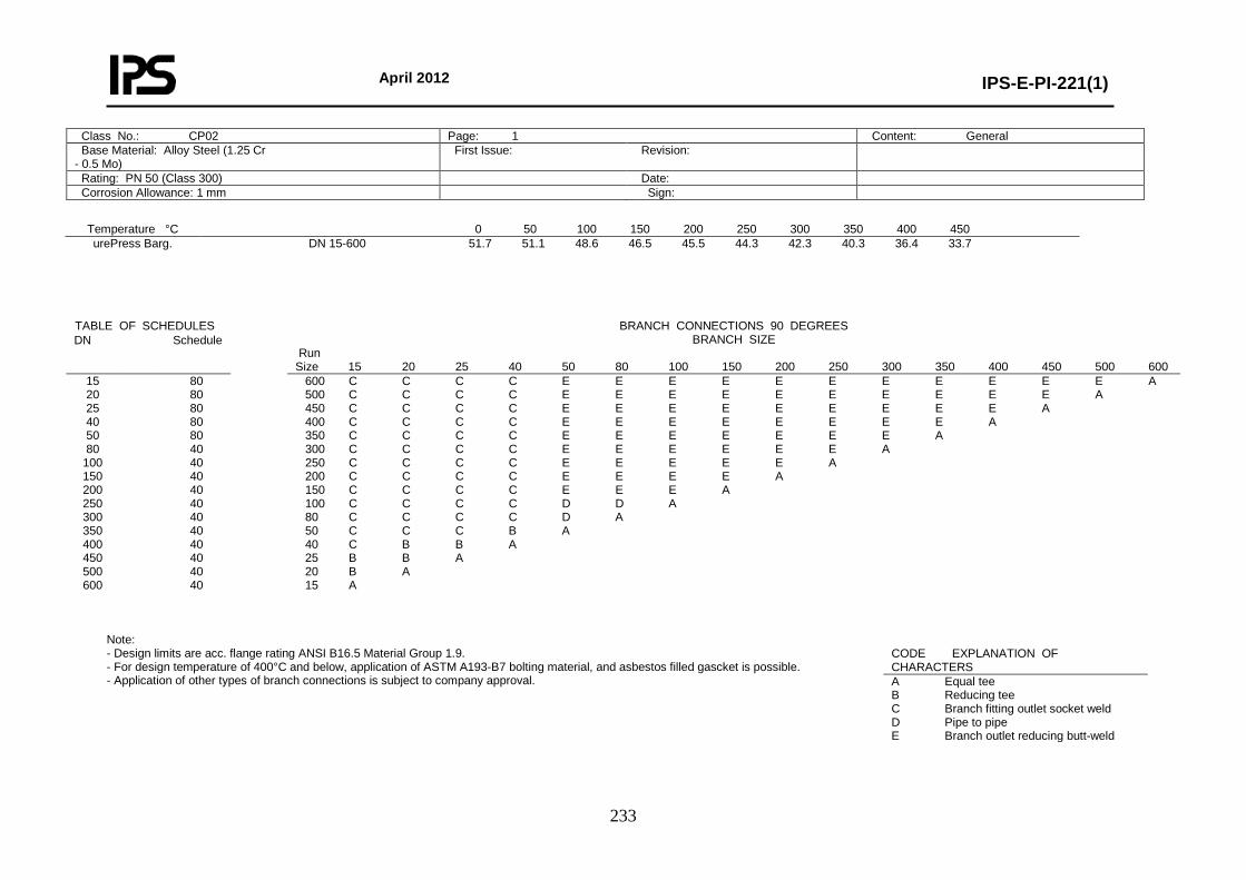
April 2012
IPS-E-PI-221(1)
233
Temperature °C 0 50 100 150 200 250 300 350 400 450 urePress Barg.
DN 15-600 51.7 51.1 48.6 46.5 45.5 44.3 42.3 40.3 36.4 33.7
Note: - Design limits are acc. flange rating ANSI B16.5 Material Group 1.9. - For design temperature of 400°C and below, application of ASTM A193-B7 bolting material, and asbestos filled gascket is possible. - Application of other types of branch connections is subject to company approval.
Class No.: CP02 Page: 1 Content: General Base Material: Alloy Steel (1.25 Cr - 0.5 Mo)
First Issue: Revision:
Rating: PN 50 (Class 300) Date: Corrosion Allowance: 1 mm Sign:
TABLE OF SCHEDULES BRANCH CONNECTIONS 90 DEGREES BRANCH SIZE
Run Size 15 20 25 40 50 80 100 150 200 250 300 350 400 450 500 600
DN Schedule
15 20 25 40 50 80
100 150 200 250 300 350 400 450 500 600
80 80 80 80 80 40 40 40 40 40 40 40 40 40 40 40
600 C C C C E E E E E E E E E E E A 500 C C C C E E E E E E E E E E A 450 C C C C E E E E E E E E E A 400 C C C C E E E E E E E E A 350 C C C C E E E E E E E A 300 C C C C E E E E E E A 250 C C C C E E E E E A 200 C C C C E E E E A 150 C C C C E E E A 100 C C C C D D A 80 C C C C D A 50 C C C B A 40 C B B A 25 B B A 20 B A 15 A
CODE EXPLANATION OF CHARACTERS A Equal tee B Reducing tee C Branch fitting outlet socket weld D Pipe to pipe E Branch outlet reducing butt-weld
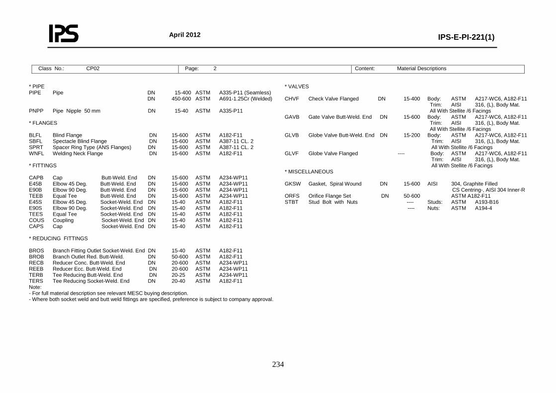
April 2012
IPS-E-PI-221(1)
234
Class No.: CP02 Page: 2 Content: Material Descriptions
* PIPE PIPE Pipe DN 15-400 ASTM A335-P11 (Seamless) DN 450-600 ASTM A691-1.25Cr (Welded) PNPP Pipe Nipple 50 mm DN 15-40 ASTM A335-P11 * FLANGES BLFL Blind Flange DN 15-600 ASTM A182-F11 SBFL Spectacle Blind Flange DN 15-600 ASTM A387-11 CL. 2 SPRT Spacer Ring Type (ANS Flanges) DN 15-600 ASTM A387-11 CL. 2 WNFL Welding Neck Flange DN 15-600 ASTM A182-F11 * FITTINGS CAPB Cap Butt-Weld. End DN 15-600 ASTM A234-WP11 E45B Elbow 45 Deg. Butt-Weld. End DN 15-600 ASTM A234-WP11 E90B Elbow 90 Deg. Butt-Weld. End DN 15-600 ASTM A234-WP11 TEEB Equal Tee Butt-Weld. End DN 15-600 ASTM A234-WP11 E45S Elbow 45 Deg. Socket-Weld. End DN 15-40 ASTM A182-F11 E90S Elbow 90 Deg. Socket-Weld. End DN 15-40 ASTM A182-F11 TEES Equal Tee Socket-Weld. End DN 15-40 ASTM A182-F11 COUS Coupling Socket-Weld. End DN 15-40 ASTM A182-F11 CAPS Cap Socket-Weld. End DN 15-40 ASTM A182-F11 * REDUCING FITTINGS BROS Branch Fitting Outlet Socket-Weld. End DN 15-40 ASTM A182-F11 BROB Branch Outlet Red. Butt-Weld. DN 50-600 ASTM A182-F11 RECB Reducer Conc. Butt-Weld. End DN 20-600 ASTM A234-WP11 REEB Reducer Ecc. Butt-Weld. End DN 20-600 ASTM A234-WP11 TERB Tee Reducing Butt-Weld. End DN 20-25 ASTM A234-WP11 TERS Tee Reducing Socket-Weld. End DN 20-40 ASTM A182-F11 Note: - For full material description see relevant MESC buying description. - Where both socket weld and butt weld fittings are specified, preference is subject to company approval.
* VALVES CHVF Check Valve Flanged DN 15-400 Body: ASTM A217-WC6, A182-F11 Trim: AISI 316, (L), Body Mat. All With Stellite /6 Facings GAVB Gate Valve Butt-Weld. End DN 15-600 Body: ASTM A217-WC6, A182-F11 Trim: AISI 316, (L), Body Mat. All With Stellite /6 Facings GLVB Globe Valve Butt-Weld. End DN 15-200 Body: ASTM A217-WC6, A182-F11 Trim: AISI 316, (L), Body Mat. All With Stellite /6 Facings GLVF Globe Valve Flanged ---- Body: ASTM A217-WC6, A182-F11 Trim: AISI 316, (L), Body Mat. All With Stellite /6 Facings * MISCELLANEOUS GKSW Gasket, Spiral Wound DN 15-600 AISI 304, Graphite Filled CS Centring-, AISI 304 Inner-R ORFS Orifice Flange Set DN 50-600 ASTM A182-F11 STBT Stud Bolt with Nuts ---- Studs: ASTM A193-B16 ---- Nuts: ASTM A194-4
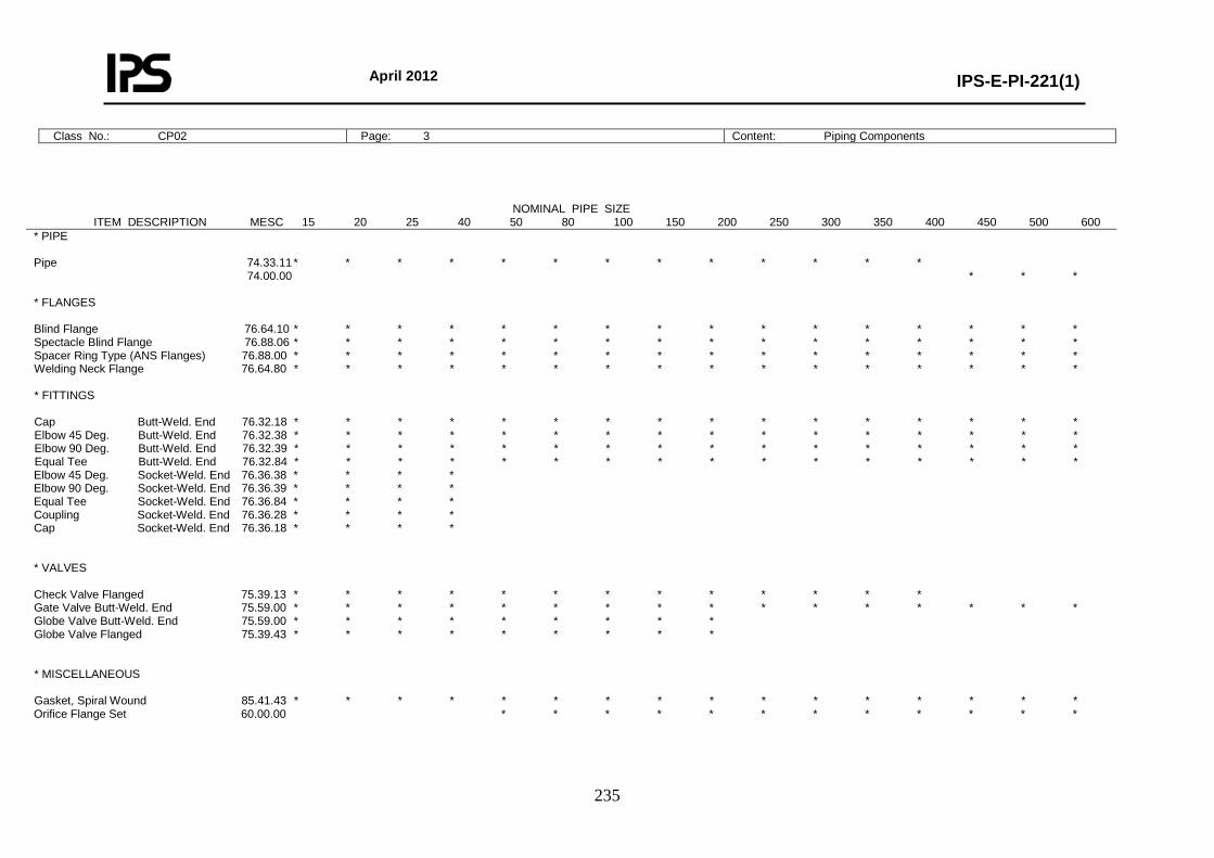
April 2012
IPS-E-PI-221(1)
235
Class No.: CP02 Page: 3 Content: Piping Components
NOMINAL PIPE SIZE ITEM DESCRIPTION MESC 15 20 25 40 50 80 100 150 200 250 300 350 400 450 500 600
* PIPE Pipe 74.33.11 * * * * * * * * * * * * * 74.00.00 * * * * FLANGES Blind Flange 76.64.10 * * * * * * * * * * * * * * * * Spectacle Blind Flange 76.88.06 * * * * * * * * * * * * * * * * Spacer Ring Type (ANS Flanges) 76.88.00 * * * * * * * * * * * * * * * * Welding Neck Flange 76.64.80 * * * * * * * * * * * * * * * * * FITTINGS Cap Butt-Weld. End 76.32.18 * * * * * * * * * * * * * * * * Elbow 45 Deg. Butt-Weld. End 76.32.38 * * * * * * * * * * * * * * * * Elbow 90 Deg. Butt-Weld. End 76.32.39 * * * * * * * * * * * * * * * * Equal Tee Butt-Weld. End 76.32.84 * * * * * * * * * * * * * * * * Elbow 45 Deg. Socket-Weld. End 76.36.38 * * * * Elbow 90 Deg. Socket-Weld. End 76.36.39 * * * * Equal Tee Socket-Weld. End 76.36.84 * * * * Coupling Socket-Weld. End 76.36.28 * * * * Cap Socket-Weld. End 76.36.18 * * * * * VALVES Check Valve Flanged 75.39.13 * * * * * * * * * * * * * Gate Valve Butt-Weld. End 75.59.00 * * * * * * * * * * * * * * * * Globe Valve Butt-Weld. End 75.59.00 * * * * * * * * * Globe Valve Flanged 75.39.43 * * * * * * * * * * MISCELLANEOUS Gasket, Spiral Wound 85.41.43 * * * * * * * * * * * * * * * * Orifice Flange Set 60.00.00 * * * * * * * * * * * *
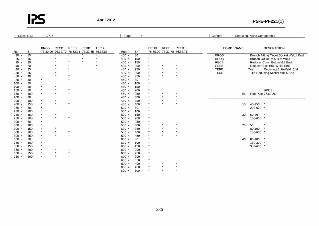
April 2012
IPS-E-PI-221(1)
236
Class No.: CP02 Page: 4 Content: Reducing Piping Components
BROB RECB REEB TERB TERS Run Br. 76.80.00 76.32.70 76.32.71 76.32.85 76.36.85
BROB RECB REEB Run Br. 76.80.00 76.32.70 76.32.71
COMP. NAME DESCRIPTION
20 × 15 * * * * 25 × 15 * * * * 25 × 20 * * * * 40 × 20 * * * 40 × 25 * * * 50 × 25 * * 50 × 40 * * 80 × 50 * * 100 × 50 * 100 × 80 * * * 150 × 80 * * * 150 × 100 * * * 200 × 80 200 × 100 * * * 200 × 150 * * * 250 × 80 * 250 × 100 * 250 × 150 * * * 250 × 200 * * * 300 × 80 * 300 × 100 * 300 × 150 * * * 300 × 200 * * * 300 × 250 * * * 350 × 80 * 350 × 100 * 350 × 150 * 350 × 200 * * * 350 × 250 * * * 350 × 300 * * *
400 × 80 * 400 × 100 * 400 × 150 * 400 × 200 * * * 400 × 250 * * * 400 × 300 * * * 400 × 350 * * * 450 × 80 * 450 × 100 * 450 × 150 * 450 × 200 * 450 × 250 * * * 450 × 300 * * * 450 × 350 * * * 450 × 400 * * * 500 × 80 * 500 × 100 * 500 × 150 * 500 × 200 * 500 × 250 * 500 × 300 * * * 500 × 350 * * * 500 × 400 * * * 500 × 450 * * * 600 × 80 * 600 × 100 * 600 × 150 * 600 × 200 * 600 × 250 * 600 × 300 * 600 × 350 * 600 × 400 * * * 600 × 450 * * * 600 × 500 * * *
BROS Branch Fitting Outlet Socket Wekd. End BROB Branch Outlet Red. Butt-Weld RECB Reducer Conc. Butt-Weld. End REEB Reducer Ecc. Butt-Weld. End TERB Tee Reducing Butt-Weld. End TERS Tee Reducing Socket-Weld. End BROS Br. Run-Pipe 76.80.26 _________________________________________________________ 15 40-150 * 200-600 * 20 50-80 * 100-600 * 25 50 * 80-100 * 150-600 * 40 80-100 * 150-300 * 350-600 *
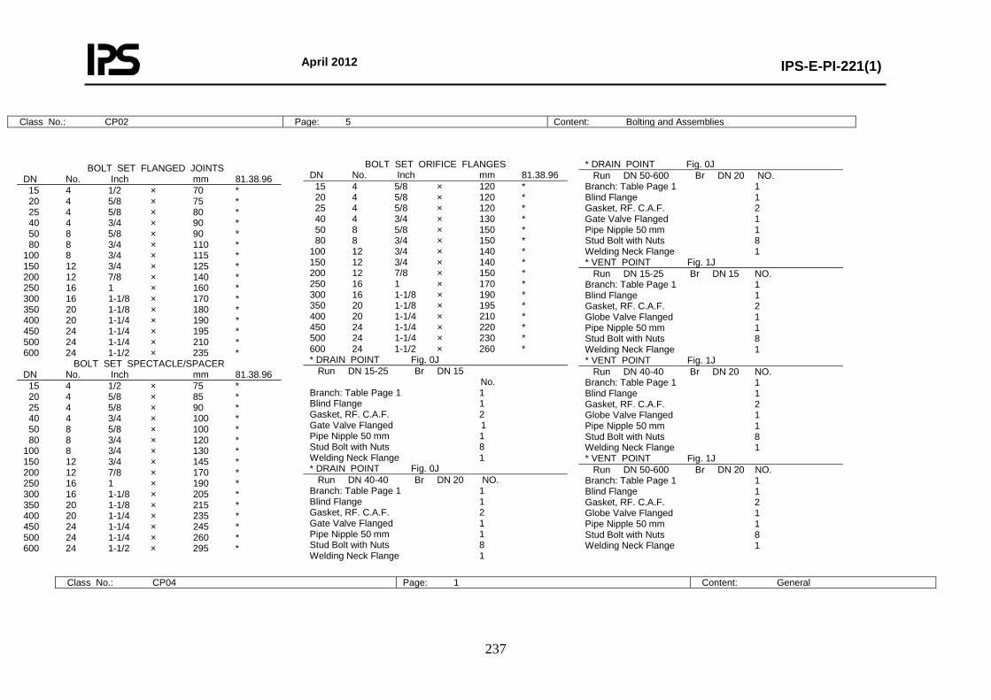
April 2012
IPS-E-PI-221(1)
237
Class No.: CP02 Page: 5 Content: Bolting and Assemblies
BOLT SET FLANGED JOINTS DN No. Inch mm 81.38.96 15 4 1/2 × 70 * 20 4 5/8 × 75 * 25 4 5/8 × 80 * 40 4 3/4 × 90 * 50 8 5/8 × 90 * 80 8 3/4 × 110 * 100 8 3/4 × 115 * 150 12 3/4 × 125 * 200 12 7/8 × 140 * 250 16 1 × 160 * 300 16 1-1/8 × 170 * 350 20 1-1/8 × 180 * 400 20 1-1/4 × 190 * 450 24 1-1/4 × 195 * 500 24 1-1/4 × 210 * 600 24 1-1/2 × 235 *
BOLT SET SPECTACLE/SPACER DN No. Inch mm 81.38.96 15 4 1/2 × 75 * 20 4 5/8 × 85 * 25 4 5/8 × 90 * 40 4 3/4 × 100 * 50 8 5/8 × 100 * 80 8 3/4 × 120 * 100 8 3/4 × 130 * 150 12 3/4 × 145 * 200 12 7/8 × 170 * 250 16 1 × 190 * 300 16 1-1/8 × 205 * 350 20 1-1/8 × 215 * 400 20 1-1/4 × 235 * 450 24 1-1/4 × 245 * 500 24 1-1/4 × 260 * 600 24 1-1/2 × 295 *
BOLT SET ORIFICE FLANGES DN No. Inch mm 81.38.96 15 4 5/8 × 120 * 20 4 5/8 × 120 * 25 4 5/8 × 120 * 40 4 3/4 × 130 * 50 8 5/8 × 150 * 80 8 3/4 × 150 * 100 12 3/4 × 140 * 150 12 3/4 × 140 * 200 12 7/8 × 150 * 250 16 1 × 170 * 300 16 1-1/8 × 190 * 350 20 1-1/8 × 195 * 400 20 1-1/4 × 210 * 450 24 1-1/4 × 220 * 500 24 1-1/4 × 230 * 600 24 1-1/2 × 260 * * DRAIN POINT Fig. 0J Run DN 15-25 Br DN 15 No. Branch: Table Page 1 1 Blind Flange 1 Gasket, RF. C.A.F. 2 Gate Valve Flanged 1 Pipe Nipple 50 mm 1 Stud Bolt with Nuts 8 Welding Neck Flange 1 * DRAIN POINT Fig. 0J Run DN 40-40 Br DN 20 NO. Branch: Table Page 1 1 Blind Flange 1 Gasket, RF. C.A.F. 2 Gate Valve Flanged 1 Pipe Nipple 50 mm 1 Stud Bolt with Nuts 8 Welding Neck Flange 1
* DRAIN POINT Fig. 0J Run DN 50-600 Br DN 20 NO. Branch: Table Page 1 1 Blind Flange 1 Gasket, RF. C.A.F. 2 Gate Valve Flanged 1 Pipe Nipple 50 mm 1 Stud Bolt with Nuts 8 Welding Neck Flange 1 * VENT POINT Fig. 1J Run DN 15-25 Br DN 15 NO. Branch: Table Page 1 1 Blind Flange 1 Gasket, RF. C.A.F. 2 Globe Valve Flanged 1 Pipe Nipple 50 mm 1 Stud Bolt with Nuts 8 Welding Neck Flange 1 * VENT POINT Fig. 1J Run DN 40-40 Br DN 20 NO. Branch: Table Page 1 1 Blind Flange 1 Gasket, RF. C.A.F. 2 Globe Valve Flanged 1 Pipe Nipple 50 mm 1 Stud Bolt with Nuts 8 Welding Neck Flange 1 * VENT POINT Fig. 1J Run DN 50-600 Br DN 20 NO. Branch: Table Page 1 1 Blind Flange 1 Gasket, RF. C.A.F. 2 Globe Valve Flanged 1 Pipe Nipple 50 mm 1 Stud Bolt with Nuts 8 Welding Neck Flange 1
Class No.: CP04 Page: 1 Content: General
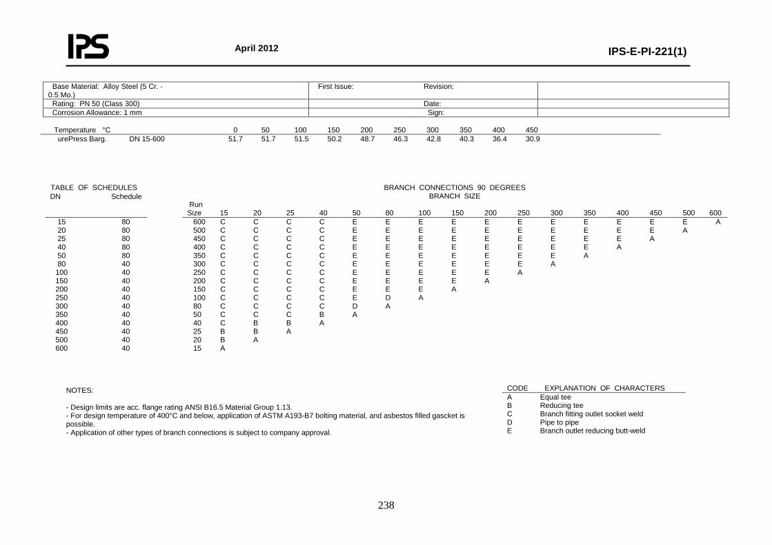
April 2012
IPS-E-PI-221(1)
238
Temperature °C 0 50 100 150 200 250 300 350 400 450 urePress Barg.
DN 15-600 51.7 51.7 51.5 50.2 48.7 46.3 42.8 40.3 36.4 30.9
NOTES: - Design limits are acc. flange rating ANSI B16.5 Material Group 1.13. - For design temperature of 400°C and below, application of ASTM A193-B7 bolting material, and asbestos filled gascket is possible. - Application of other types of branch connections is subject to company approval.
Base Material: Alloy Steel (5 Cr. - 0.5 Mo.)
First Issue: Revision:
Rating: PN 50 (Class 300) Date: Corrosion Allowance: 1 mm Sign:
TABLE OF SCHEDULES BRANCH CONNECTIONS 90 DEGREES BRANCH SIZE
Run Size 15 20 25 40 50 80 100 150 200 250 300 350 400 450 500 600
DN Schedule
15 20 25 40 50 80
100 150 200 250 300 350 400 450 500 600
80 80 80 80 80 40 40 40 40 40 40 40 40 40 40 40
600 C C C C E E E E E E E E E E E A 500 C C C C E E E E E E E E E E A 450 C C C C E E E E E E E E E A 400 C C C C E E E E E E E E A 350 C C C C E E E E E E E A 300 C C C C E E E E E E A 250 C C C C E E E E E A 200 C C C C E E E E A 150 C C C C E E E A 100 C C C C E D A 80 C C C C D A 50 C C C B A 40 C B B A 25 B B A 20 B A 15 A
CODE EXPLANATION OF CHARACTERS A Equal tee B Reducing tee C Branch fitting outlet socket weld D Pipe to pipe E Branch outlet reducing butt-weld
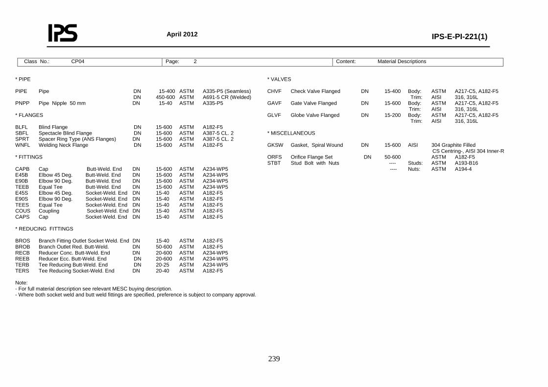
April 2012
IPS-E-PI-221(1)
239
Class No.: CP04 Page: 2 Content: Material Descriptions
* PIPE PIPE Pipe DN 15-400 ASTM A335-P5 (Seamless) DN 450-600 ASTM A691-5 CR (Welded) PNPP Pipe Nipple 50 mm DN 15-40 ASTM A335-P5 * FLANGES BLFL Blind Flange DN 15-600 ASTM A182-F5 SBFL Spectacle Blind Flange DN 15-600 ASTM A387-5 CL. 2 SPRT Spacer Ring Type (ANS Flanges) DN 15-600 ASTM A387-5 CL. 2 WNFL Welding Neck Flange DN 15-600 ASTM A182-F5 * FITTINGS CAPB Cap Butt-Weld. End DN 15-600 ASTM A234-WP5 E45B Elbow 45 Deg. Butt-Weld. End DN 15-600 ASTM A234-WP5 E90B Elbow 90 Deg. Butt-Weld. End DN 15-600 ASTM A234-WP5 TEEB Equal Tee Butt-Weld. End DN 15-600 ASTM A234-WP5 E45S Elbow 45 Deg. Socket-Weld. End DN 15-40 ASTM A182-F5 E90S Elbow 90 Deg. Socket-Weld. End DN 15-40 ASTM A182-F5 TEES Equal Tee Socket-Weld. End DN 15-40 ASTM A182-F5 COUS Coupling Socket-Weld. End DN 15-40 ASTM A182-F5 CAPS Cap Socket-Weld. End DN 15-40 ASTM A182-F5 * REDUCING FITTINGS BROS Branch Fitting Outlet Socket Weld. End DN 15-40 ASTM A182-F5 BROB Branch Outlet Red. Butt-Weld. DN 50-600 ASTM A182-F5 RECB Reducer Conc. Butt-Weld. End DN 20-600 ASTM A234-WP5 REEB Reducer Ecc. Butt-Weld. End DN 20-600 ASTM A234-WP5 TERB Tee Reducing Butt-Weld. End DN 20-25 ASTM A234-WP5 TERS Tee Reducing Socket-Weld. End DN 20-40 ASTM A182-F5 Note: - For full material description see relevant MESC buying description. - Where both socket weld and butt weld fittings are specified, preference is subject to company approval.
* VALVES CHVF Check Valve Flanged DN 15-400 Body: ASTM A217-C5, A182-F5 Trim: AISI 316, 316L GAVF Gate Valve Flanged DN 15-600 Body: ASTM A217-C5, A182-F5 Trim: AISI 316, 316L GLVF Globe Valve Flanged DN 15-200 Body: ASTM A217-C5, A182-F5 Trim: AISI 316, 316L * MISCELLANEOUS GKSW Gasket, Spiral Wound DN 15-600 AISI 304 Graphite Filled CS Centring-, AISI 304 Inner-R ORFS Orifice Flange Set DN 50-600 ASTM A182-F5 STBT Stud Bolt with Nuts ---- Studs: ASTM A193-B16 ---- Nuts: ASTM A194-4
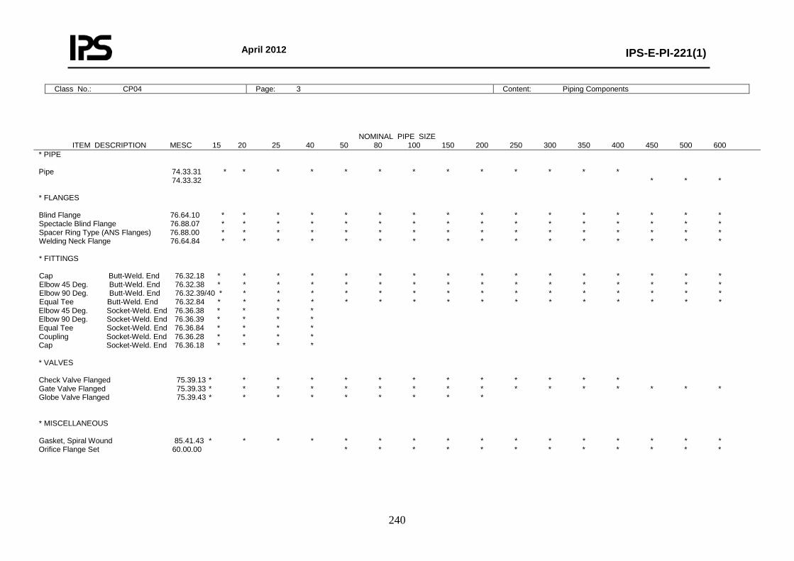
April 2012
IPS-E-PI-221(1)
240
Class No.: CP04 Page: 3 Content: Piping Components
NOMINAL PIPE SIZE ITEM DESCRIPTION MESC 15 20 25 40 50 80 100 150 200 250 300 350 400 450 500 600
* PIPE Pipe 74.33.31 * * * * * * * * * * * * * 74.33.32 * * * * FLANGES Blind Flange 76.64.10 * * * * * * * * * * * * * * * * Spectacle Blind Flange 76.88.07 * * * * * * * * * * * * * * * * Spacer Ring Type (ANS Flanges) 76.88.00 * * * * * * * * * * * * * * * * Welding Neck Flange 76.64.84 * * * * * * * * * * * * * * * * * FITTINGS Cap Butt-Weld. End 76.32.18 * * * * * * * * * * * * * * * * Elbow 45 Deg. Butt-Weld. End 76.32.38 * * * * * * * * * * * * * * * * Elbow 90 Deg. Butt-Weld. End 76.32.39/40 * * * * * * * * * * * * * * * * Equal Tee Butt-Weld. End 76.32.84 * * * * * * * * * * * * * * * * Elbow 45 Deg. Socket-Weld. End 76.36.38 * * * * Elbow 90 Deg. Socket-Weld. End 76.36.39 * * * * Equal Tee Socket-Weld. End 76.36.84 * * * * Coupling Socket-Weld. End 76.36.28 * * * * Cap Socket-Weld. End 76.36.18 * * * * * VALVES Check Valve Flanged 75.39.13 * * * * * * * * * * * * * Gate Valve Flanged 75.39.33 * * * * * * * * * * * * * * * * Globe Valve Flanged 75.39.43 * * * * * * * * * * MISCELLANEOUS Gasket, Spiral Wound 85.41.43 * * * * * * * * * * * * * * * * Orifice Flange Set 60.00.00 * * * * * * * * * * * *
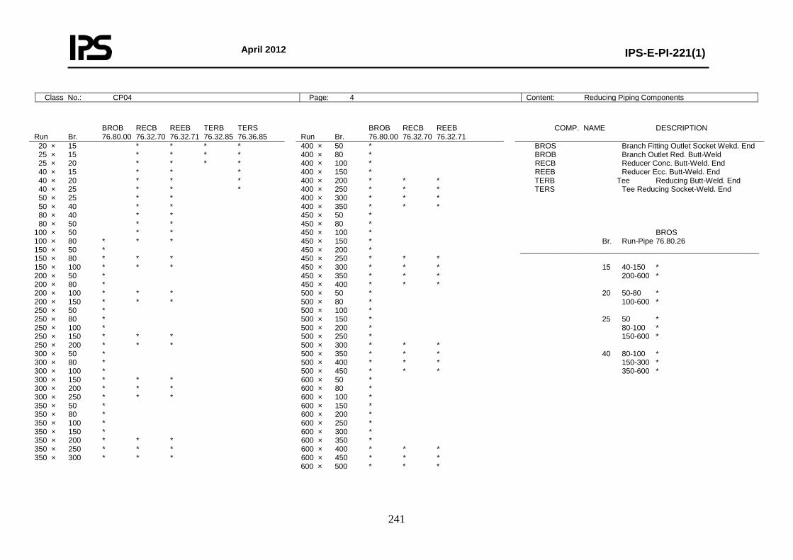
April 2012
IPS-E-PI-221(1)
241
Class No.: CP04 Page: 4 Content: Reducing Piping Components
BROB RECB REEB TERB TERS Run Br. 76.80.00 76.32.70 76.32.71 76.32.85 76.36.85
BROB RECB REEB Run Br. 76.80.00 76.32.70 76.32.71
COMP. NAME DESCRIPTION
20 × 15 * * * * 25 × 15 * * * * 25 × 20 * * * * 40 × 15 * * * 40 × 20 * * * 40 × 25 * * * 50 × 25 * * 50 × 40 * * 80 × 40 * * 80 × 50 * * 100 × 50 * * 100 × 80 * * * 150 × 50 * 150 × 80 * * * 150 × 100 * * * 200 × 50 * 200 × 80 * 200 × 100 * * * 200 × 150 * * * 250 × 50 * 250 × 80 * 250 × 100 * 250 × 150 * * * 250 × 200 * * * 300 × 50 * 300 × 80 * 300 × 100 * 300 × 150 * * * 300 × 200 * * * 300 × 250 * * * 350 × 50 * 350 × 80 * 350 × 100 * 350 × 150 * 350 × 200 * * * 350 × 250 * * * 350 × 300 * * *
400 × 50 * 400 × 80 * 400 × 100 * 400 × 150 * 400 × 200 * * * 400 × 250 * * * 400 × 300 * * * 400 × 350 * * * 450 × 50 * 450 × 80 * 450 × 100 * 450 × 150 * 450 × 200 * 450 × 250 * * * 450 × 300 * * * 450 × 350 * * * 450 × 400 * * * 500 × 50 * 500 × 80 * 500 × 100 * 500 × 150 * 500 × 200 * 500 × 250 * 500 × 300 * * * 500 × 350 * * * 500 × 400 * * * 500 × 450 * * * 600 × 50 * 600 × 80 * 600 × 100 * 600 × 150 * 600 × 200 * 600 × 250 * 600 × 300 * 600 × 350 * 600 × 400 * * * 600 × 450 * * * 600 × 500 * * *
BROS Branch Fitting Outlet Socket Wekd. End BROB Branch Outlet Red. Butt-Weld RECB Reducer Conc. Butt-Weld. End REEB Reducer Ecc. Butt-Weld. End TERB Tee Reducing Butt-Weld. End TERS Tee Reducing Socket-Weld. End BROS Br. Run-Pipe 76.80.26 _________________________________________________________ 15 40-150 * 200-600 * 20 50-80 * 100-600 * 25 50 * 80-100 * 150-600 * 40 80-100 * 150-300 * 350-600 *
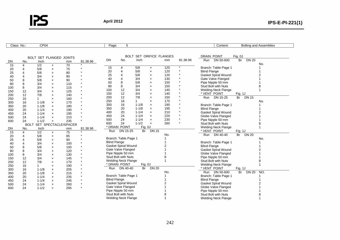
April 2012
IPS-E-PI-221(1)
242
Class No.: CP04 Page: 5 Content: Bolting and Assemblies
BOLT SET FLANGED JOINTS DN No. Inch mm 81.38.96 15 4 1/2 × 70 * 20 4 5/8 × 75 * 25 4 5/8 × 80 * 40 4 3/4 × 90 * 50 8 5/8 × 90 * 80 8 3/4 × 110 * 100 8 3/4 × 115 * 150 12 3/4 × 125 * 200 12 7/8 × 140 * 250 16 1 × 160 * 300 16 1-1/8 × 170 * 350 20 1-1/8 × 180 * 400 20 1-1/4 × 190 * 450 24 1-1/4 × 195 * 500 24 1-1/4 × 210 * 600 24 1-1/2 × 235 *
BOLT SET SPECTACLE/SPACER DN No. Inch mm 81.38.96 15 4 1/2 × 75 * 20 4 5/8 × 85 * 25 4 5/8 × 90 * 40 4 3/4 × 100 * 50 8 5/8 × 100 * 80 8 3/4 × 120 * 100 8 3/4 × 130 * 150 12 3/4 × 145 * 200 12 7/8 × 170 * 250 16 1 × 190 * 300 16 1-1/8 × 205 * 350 20 1-1/8 × 215 * 400 20 1-1/4 × 235 * 450 24 1-1/4 × 245 * 500 24 1-1/4 × 260 * 600 24 1-1/2 × 295 *
BOLT SET ORIFICE FLANGES DN No. Inch mm 81.38.96 15 4 5/8 × 120 * 20 4 5/8 × 120 * 25 4 5/8 × 120 * 40 4 3/4 × 130 * 50 8 5/8 × 150 * 80 8 3/4 × 150 * 100 12 3/4 × 140 * 150 12 3/4 × 140 * 200 12 7/8 × 150 * 250 16 1 × 170 * 300 16 1-1/8 × 190 * 350 20 1-1/8 × 195 * 400 20 1-1/4 × 210 * 450 24 1-1/4 × 220 * 500 24 1-1/4 × 230 * 600 24 1-1/2 × 260 * * DRAIN POINT Fig. 0J Run DN 15-25 Br DN 15 No. Branch: Table Page 1 1 Blind Flange 1 Gasket Spiral Wound 2 Gate Valve Flanged 1 Pipe Nipple 50 mm 1 Stud Bolt with Nuts 8 Welding Neck Flange 1 * DRAIN POINT Fig. 0J Run DN 40-40 Br DN 20 No. Branch: Table Page 1 1 Blind Flange 1 Gasket Spiral Wound 2 Gate Valve Flanged 1 Pipe Nipple 50 mm 1 Stud Bolt with Nuts 8 Welding Neck Flange 1
DRAIN POINT Fig. 0J Run DN 50-600 Br DN 20 No. Branch: Table Page 1 1 Blind Flange 1 Gasket Spiral Wound 2 Gate Valve Flanged 1 Pipe Nipple 50 mm 1 Stud Bolt with Nuts 8 Welding Neck Flange 1 * VENT POINT Fig. 1J Run DN 15-25 Br DN 15 No. Branch: Table Page 1 1 Blind Flange 1 Gasket Spiral Wound 2 Globe Valve Flanged 1 Pipe Nipple 50 mm 1 Stud Bolt with Nuts 8 Welding Neck Flange 1 * VENT POINT Fig. 1J Run DN 40-40 Br DN 20 No. Branch: Table Page 1 1 Blind Flange 1 Gasket Spiral Wound 2 Globe Valve Flanged 1 Pipe Nipple 50 mm 1 Stud Bolt with Nuts 8 Welding Neck Flange 1 * VENT POINT Fig. 1J Run DN 50-600 Br DN 20 NO. Branch: Table Page 1 1 Blind Flange 1 Gasket Spiral Wound 2 Globe Valve Flanged 1 Pipe Nipple 50 mm 1 Stud Bolt with Nuts 8 Welding Neck Flange 1
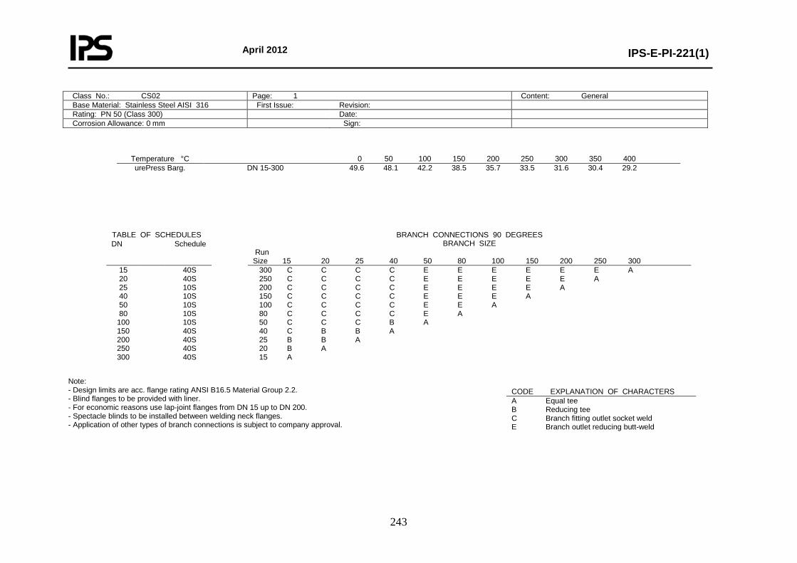
April 2012
IPS-E-PI-221(1)
243
Temperature °C 0 50 100 150 200 250 300 350 400 urePress Barg.
DN 15-300 49.6 48.1 42.2 38.5 35.7 33.5 31.6 30.4 29.2
Note: - Design limits are acc. flange rating ANSI B16.5 Material Group 2.2. - Blind flanges to be provided with liner. - For economic reasons use lap-joint flanges from DN 15 up to DN 200. - Spectacle blinds to be installed between welding neck flanges. - Application of other types of branch connections is subject to company approval.
Class No.: CS02 Page: 1 Content: General Base Material: Stainless Steel AISI 316 First Issue: Revision: Rating: PN 50 (Class 300) Date: Corrosion Allowance: 0 mm Sign:
TABLE OF SCHEDULES BRANCH CONNECTIONS 90 DEGREES BRANCH SIZE
Run Size 15 20 25 40 50 80 100 150 200 250 300
DN Schedule
15 20 25 40 50 80
100 150 200 250 300
40S 40S 10S 10S 10S 10S 10S 40S 40S 40S 40S
300 C C C C E E E E E E A 250 C C C C E E E E E A 200 C C C C E E E E A 150 C C C C E E E A 100 C C C C E E A 80 C C C C E A 50 C C C B A 40 C B B A 25 B B A 20 B A 15 A
CODE EXPLANATION OF CHARACTERS A Equal tee B Reducing tee C Branch fitting outlet socket weld E Branch outlet reducing butt-weld
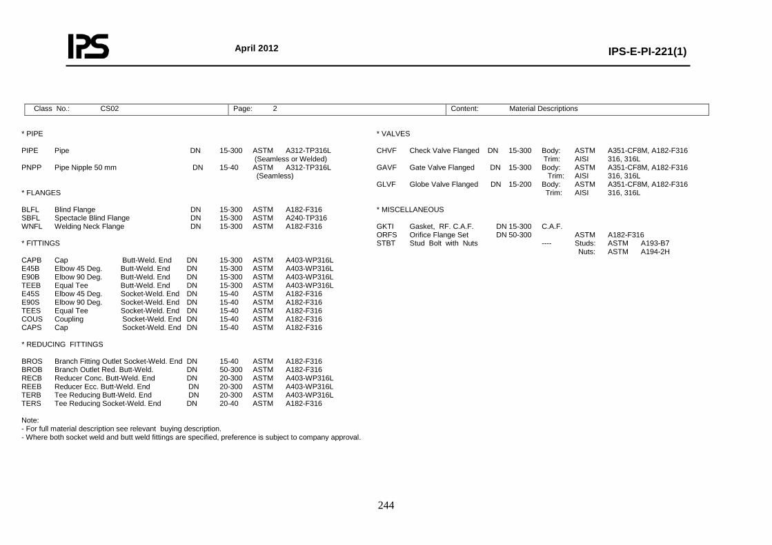
April 2012
IPS-E-PI-221(1)
244
Class No.: CS02 Page: 2 Content: Material Descriptions
* PIPE PIPE Pipe DN 15-300 ASTM A312-TP316L (Seamless or Welded) PNPP Pipe Nipple 50 mm DN 15-40 ASTM A312-TP316L (Seamless) * FLANGES BLFL Blind Flange DN 15-300 ASTM A182-F316 SBFL Spectacle Blind Flange DN 15-300 ASTM A240-TP316 WNFL Welding Neck Flange DN 15-300 ASTM A182-F316 * FITTINGS CAPB Cap Butt-Weld. End DN 15-300 ASTM A403-WP316L E45B Elbow 45 Deg. Butt-Weld. End DN 15-300 ASTM A403-WP316L E90B Elbow 90 Deg. Butt-Weld. End DN 15-300 ASTM A403-WP316L TEEB Equal Tee Butt-Weld. End DN 15-300 ASTM A403-WP316L E45S Elbow 45 Deg. Socket-Weld. End DN 15-40 ASTM A182-F316 E90S Elbow 90 Deg. Socket-Weld. End DN 15-40 ASTM A182-F316 TEES Equal Tee Socket-Weld. End DN 15-40 ASTM A182-F316 COUS Coupling Socket-Weld. End DN 15-40 ASTM A182-F316 CAPS Cap Socket-Weld. End DN 15-40 ASTM A182-F316 * REDUCING FITTINGS BROS Branch Fitting Outlet Socket-Weld. End DN 15-40 ASTM A182-F316 BROB Branch Outlet Red. Butt-Weld. DN 50-300 ASTM A182-F316 RECB Reducer Conc. Butt-Weld. End DN 20-300 ASTM A403-WP316L REEB Reducer Ecc. Butt-Weld. End DN 20-300 ASTM A403-WP316L TERB Tee Reducing Butt-Weld. End DN 20-300 ASTM A403-WP316L TERS Tee Reducing Socket-Weld. End DN 20-40 ASTM A182-F316 Note: - For full material description see relevant buying description. - Where both socket weld and butt weld fittings are specified, preference is subject to company approval.
* VALVES CHVF Check Valve Flanged DN 15-300 Body: ASTM A351-CF8M, A182-F316 Trim: AISI 316, 316L GAVF Gate Valve Flanged DN 15-300 Body: ASTM A351-CF8M, A182-F316 Trim: AISI 316, 316L GLVF Globe Valve Flanged DN 15-200 Body: ASTM A351-CF8M, A182-F316 Trim: AISI 316, 316L * MISCELLANEOUS GKTI Gasket, RF. C.A.F. DN 15-300 C.A.F. ORFS Orifice Flange Set DN 50-300 ASTM A182-F316 STBT Stud Bolt with Nuts ---- Studs: ASTM A193-B7 Nuts: ASTM A194-2H
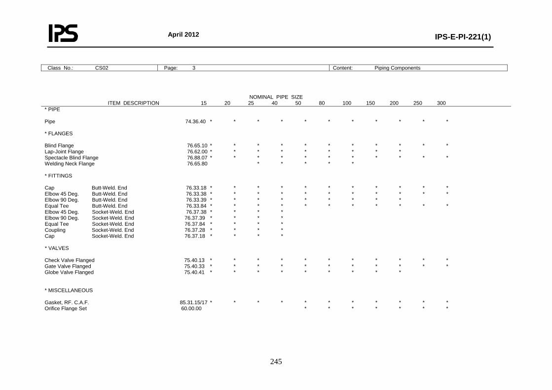
April 2012
IPS-E-PI-221(1)
245
Class No.: CS02 Page: 3 Content: Piping Components
NOMINAL PIPE SIZE ITEM DESCRIPTION 15 20 25 40 50 80 100 150 200 250 300
* PIPE Pipe 74.36.40 * * * * * * * * * * * * FLANGES Blind Flange 76.65.10 * * * * * * * * * * * Lap-Joint Flange 76.62.00 * * * * * * * * * Spectacle Blind Flange 76.88.07 * * * * * * * * * * * Welding Neck Flange 76.65.80 * * * * * * FITTINGS Cap Butt-Weld. End 76.33.18 * * * * * * * * * * * Elbow 45 Deg. Butt-Weld. End 76.33.38 * * * * * * * * * * * Elbow 90 Deg. Butt-Weld. End 76.33.39 * * * * * * * * * Equal Tee Butt-Weld. End 76.33.84 * * * * * * * * * * * Elbow 45 Deg. Socket-Weld. End 76.37.38 * * * * Elbow 90 Deg. Socket-Weld. End 76.37.39 * * * * Equal Tee Socket-Weld. End 76.37.84 * * * * Coupling Socket-Weld. End 76.37.28 * * * * Cap Socket-Weld. End 76.37.18 * * * * * VALVES Check Valve Flanged 75.40.13 * * * * * * * * * * * Gate Valve Flanged 75.40.33 * * * * * * * * * * * Globe Valve Flanged 75.40.41 * * * * * * * * * * MISCELLANEOUS Gasket, RF. C.A.F. 85.31.15/17 * * * * * * * * * * * Orifice Flange Set 60.00.00 * * * * * * *
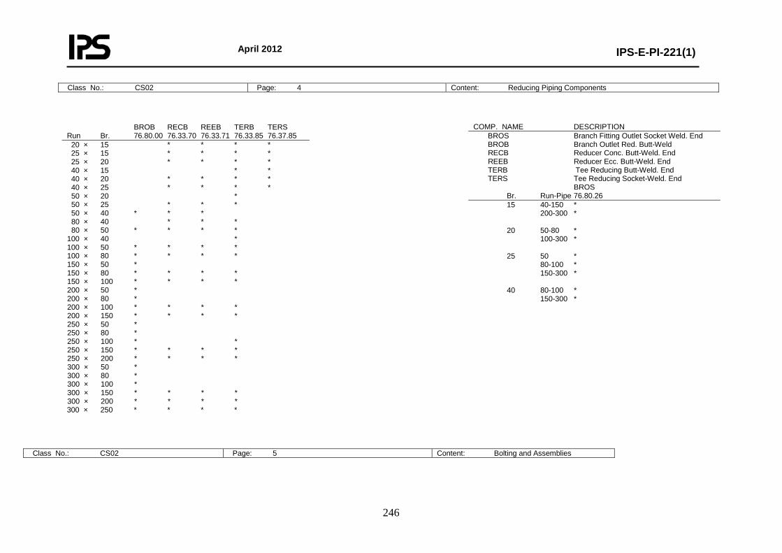
April 2012
IPS-E-PI-221(1)
246
Class No.: CS02 Page: 4 Content: Reducing Piping Components
Class No.: CS02 Page: 5 Content: Bolting and Assemblies
BROB RECB REEB TERB TERS Run Br. 76.80.00 76.33.70 76.33.71 76.33.85 76.37.85 20 × 15 * * * * 25 × 15 * * * * 25 × 20 * * * * 40 × 15 * * 40 × 20 * * * * 40 × 25 * * * * 50 × 20 * 50 × 25 * * * 50 × 40 * * * 80 × 40 * * * 80 × 50 * * * * 100 × 40 * 100 × 50 * * * * 100 × 80 * * * * 150 × 50 * 150 × 80 * * * * 150 × 100 * * * * 200 × 50 * 200 × 80 * 200 × 100 * * * * 200 × 150 * * * * 250 × 50 * 250 × 80 * 250 × 100 * * 250 × 150 * * * * 250 × 200 * * * * 300 × 50 * 300 × 80 * 300 × 100 * 300 × 150 * * * * 300 × 200 * * * * 300 × 250 * * * *
COMP. NAME DESCRIPTION BROS Branch Fitting Outlet Socket Weld. End BROB Branch Outlet Red. Butt-Weld RECB Reducer Conc. Butt-Weld. End REEB Reducer Ecc. Butt-Weld. End TERB Tee Reducing Butt-Weld. End TERS Tee Reducing Socket-Weld. End BROS Br. Run-Pipe 76.80.26 15 40-150 * 200-300 * 20 50-80 * 100-300 * 25 50 * 80-100 * 150-300 * 40 80-100 * 150-300 *
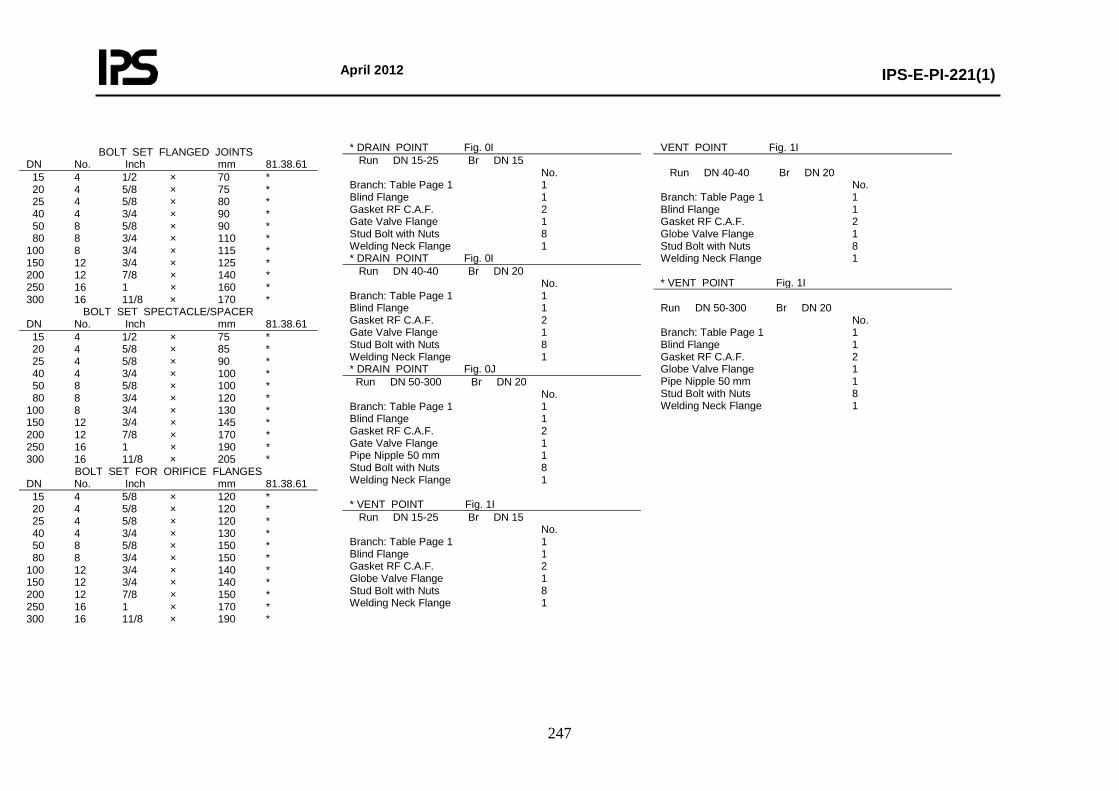
April 2012
IPS-E-PI-221(1)
247
BOLT SET FLANGED JOINTS DN No. Inch mm 81.38.61 15 4 1/2 × 70 * 20 4 5/8 × 75 * 25 4 5/8 × 80 * 40 4 3/4 × 90 * 50 8 5/8 × 90 * 80 8 3/4 × 110 * 100 8 3/4 × 115 * 150 12 3/4 × 125 * 200 12 7/8 × 140 * 250 16 1 × 160 * 300 16 11/8 × 170 *
BOLT SET SPECTACLE/SPACER DN No. Inch mm 81.38.61 15 4 1/2 × 75 * 20 4 5/8 × 85 * 25 4 5/8 × 90 * 40 4 3/4 × 100 * 50 8 5/8 × 100 * 80 8 3/4 × 120 * 100 8 3/4 × 130 * 150 12 3/4 × 145 * 200 12 7/8 × 170 * 250 16 1 × 190 * 300 16 11/8 × 205 *
BOLT SET FOR ORIFICE FLANGES DN No. Inch mm 81.38.61 15 4 5/8 × 120 * 20 4 5/8 × 120 * 25 4 5/8 × 120 * 40 4 3/4 × 130 * 50 8 5/8 × 150 * 80 8 3/4 × 150 * 100 12 3/4 × 140 * 150 12 3/4 × 140 * 200 12 7/8 × 150 * 250 16 1 × 170 * 300 16 11/8 × 190 *
* DRAIN POINT Fig. 0I Run DN 15-25 Br DN 15 No. Branch: Table Page 1 1 Blind Flange 1 Gasket RF C.A.F. 2 Gate Valve Flange 1 Stud Bolt with Nuts 8 Welding Neck Flange 1 * DRAIN POINT Fig. 0I Run DN 40-40 Br DN 20 No. Branch: Table Page 1 1 Blind Flange 1 Gasket RF C.A.F. 2 Gate Valve Flange 1 Stud Bolt with Nuts 8 Welding Neck Flange 1 * DRAIN POINT Fig. 0J Run DN 50-300 Br DN 20 No. Branch: Table Page 1 1 Blind Flange 1 Gasket RF C.A.F. 2 Gate Valve Flange 1 Pipe Nipple 50 mm 1 Stud Bolt with Nuts 8 Welding Neck Flange 1 * VENT POINT Fig. 1I Run DN 15-25 Br DN 15 No. Branch: Table Page 1 1 Blind Flange 1 Gasket RF C.A.F. 2 Globe Valve Flange 1 Stud Bolt with Nuts 8 Welding Neck Flange 1
VENT POINT Fig. 1I Run DN 40-40 Br DN 20 No. Branch: Table Page 1 1 Blind Flange 1 Gasket RF C.A.F. 2 Globe Valve Flange 1 Stud Bolt with Nuts 8 Welding Neck Flange 1 * VENT POINT Fig. 1I Run DN 50-300 Br DN 20 No. Branch: Table Page 1 1 Blind Flange 1 Gasket RF C.A.F. 2 Globe Valve Flange 1 Pipe Nipple 50 mm 1 Stud Bolt with Nuts 8 Welding Neck Flange 1
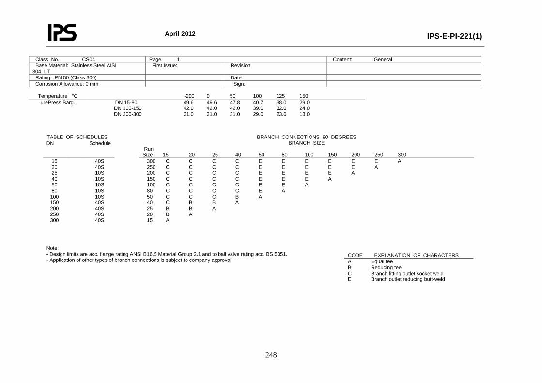
April 2012
IPS-E-PI-221(1)
248
Temperature °C -200 0 50 100 125 150 urePress Barg.
DN 15-80 49.6 49.6 47.8 40.7 38.0 29.0 DN 100-150 42.0 42.0 42.0 39.0 32.0 24.0 DN 200-300 31.0 31.0 31.0 29.0 23.0 18.0
Note: - Design limits are acc. flange rating ANSI B16.5 Material Group 2.1 and to ball valve rating acc. BS 5351. - Application of other types of branch connections is subject to company approval.
Class No.: CS04 Page: 1 Content: General Base Material: Stainless Steel AISI 304, LT
First Issue: Revision:
Rating: PN 50 (Class 300) Date: Corrosion Allowance: 0 mm Sign:
TABLE OF SCHEDULES BRANCH CONNECTIONS 90 DEGREES BRANCH SIZE
Run Size 15 20 25 40 50 80 100 150 200 250 300
DN Schedule
15 20 25 40 50 80
100 150 200 250 300
40S 40S 10S 10S 10S 10S 10S 40S 40S 40S 40S
300 C C C C E E E E E E A 250 C C C C E E E E E A 200 C C C C E E E E A 150 C C C C E E E A 100 C C C C E E A 80 C C C C E A 50 C C C B A 40 C B B A 25 B B A 20 B A 15 A
CODE EXPLANATION OF CHARACTERS A Equal tee B Reducing tee C Branch fitting outlet socket weld E Branch outlet reducing butt-weld
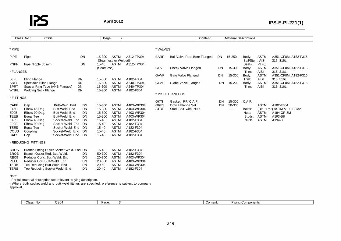
April 2012
IPS-E-PI-221(1)
249
Class No.: CS04 Page: 2 Content: Material Descriptions
* PIPE PIPE Pipe DN 15-300 ASTM A312-TP304 (Seamless or Welded) PNPP Pipe Nipple 50 mm DN 15-40 ASTM A312-TP304 (Seamless) * FLANGES BLFL Blind Flange DN 15-300 ASTM A182-F304 SBFL Spectacle Blind Flange DN 15-300 ASTM A240-TP304 SPRT Spacer Ring Type (ANS Flanges) DN 15-300 ASTM A240-TP304 WNFL Welding Neck Flange DN 15-300 ASTM A182-F304 * FITTINGS CAPB Cap Butt-Weld. End DN 15-300 ASTM A403-WP304 E45B Elbow 45 Deg. Butt-Weld. End DN 15-300 ASTM A403-WP304 E90B Elbow 90 Deg. Butt-Weld. End DN 15-300 ASTM A403-WP304 TEEB Equal Tee Butt-Weld. End DN 15-300 ASTM A403-WP304 E45S Elbow 45 Deg. Socket-Weld. End DN 15-40 ASTM A182-F304 E90S Elbow 90 Deg. Socket-Weld. End DN 15-40 ASTM A182-F304 TEES Equal Tee Socket-Weld. End DN 15-40 ASTM A182-F304 COUS Coupling Socket-Weld. End DN 15-40 ASTM A182-F304 CAPS Cap Socket-Weld. End DN 15-40 ASTM A182-F304 * REDUCING FITTINGS BROS Branch Fitting Outlet Socket-Weld. End DN 15-40 ASTM A182-F304 BROB Branch Outlet Red. Butt-Weld. DN 50-300 ASTM A182-F304 RECB Reducer Conc. Butt-Weld. End DN 20-300 ASTM A403-WP304 REEB Reducer Ecc. Butt-Weld. End DN 20-300 ASTM A403-WP304 TERB Tee Reducing Butt-Weld. End DN 20-50 ASTM A403-WP304 TERS Tee Reducing Socket-Weld. End DN 20-40 ASTM A182-F304 Note: - For full material description see relevant buying description. - Where both socket weld and butt weld fittings are specified, preference is subject to company approval.
* VALVES BARF Ball Valve Red. Bore Flanged DN 15-250 Body: ASTM A351-CF8M, A182-F316 Ball/Stem: AISI 316, 316L Seats: PTFE GHVF Check Valve Flanged DN 15-300 Body: ASTM A351-CF8M, A182-F316 Trim: AISI 316, 316L GAVF Gate Valve Flanged DN 15-300 Body: ASTM A351-CF8M, A182-F316 Trim: AISI 316, 316L GLVF Globe Valve Flanged DN 15-200 Body: ASTM A351-CF8M, A182-F316 Trim: AISI 316, 316L * MISCELLANEOUS GKTI Gasket, RF. C.A.F. DN 15-300 C.A.F. ORFS Orifice Flange Set DN 50-300 ASTM A182-F304 STBT Stud Bolt with Nuts - --- Bollts: (Dia. 1.½") ASTM A193-B8M2 Nuts: ASTM A194 GR 8M Studs: ASTM A193-B8 Nuts: ASTM A194-8
Class No.: CS04 Page: 3 Content: Piping Components
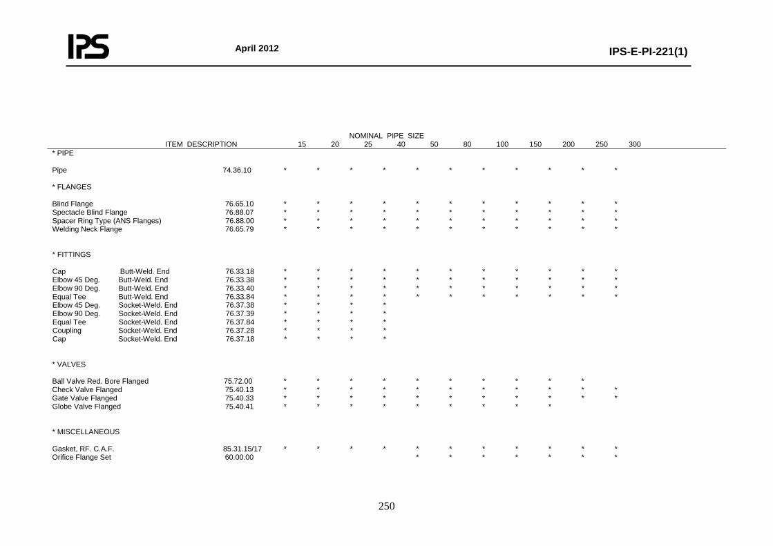
April 2012
IPS-E-PI-221(1)
250
NOMINAL PIPE SIZE ITEM DESCRIPTION 15 20 25 40 50 80 100 150 200 250 300
* PIPE Pipe 74.36.10 * * * * * * * * * * * * FLANGES Blind Flange 76.65.10 * * * * * * * * * * * Spectacle Blind Flange 76.88.07 * * * * * * * * * * * Spacer Ring Type (ANS Flanges) 76.88.00 * * * * * * * * * * * Welding Neck Flange 76.65.79 * * * * * * * * * * * * FITTINGS Cap Butt-Weld. End 76.33.18 * * * * * * * * * * * Elbow 45 Deg. Butt-Weld. End 76.33.38 * * * * * * * * * * * Elbow 90 Deg. Butt-Weld. End 76.33.40 * * * * * * * * * * * Equal Tee Butt-Weld. End 76.33.84 * * * * * * * * * * * Elbow 45 Deg. Socket-Weld. End 76.37.38 * * * * Elbow 90 Deg. Socket-Weld. End 76.37.39 * * * * Equal Tee Socket-Weld. End 76.37.84 * * * * Coupling Socket-Weld. End 76.37.28 * * * * Cap Socket-Weld. End 76.37.18 * * * * * VALVES Ball Valve Red. Bore Flanged 75.72.00 * * * * * * * * * * Check Valve Flanged 75.40.13 * * * * * * * * * * * Gate Valve Flanged 75.40.33 * * * * * * * * * * * Globe Valve Flanged 75.40.41 * * * * * * * * * * MISCELLANEOUS Gasket, RF. C.A.F. 85.31.15/17 * * * * * * * * * * * Orifice Flange Set 60.00.00 * * * * * * *
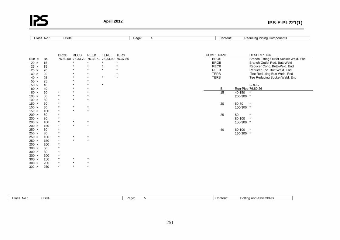
April 2012
IPS-E-PI-221(1)
251
Class No.: CS04 Page: 4 Content: Reducing Piping Components
Class No.: CS04 Page: 5 Content: Bolting and Assemblies
BROB RECB REEB TERB TERS Run × Br. 76.80.00 76.33.70 76.33.71 76.33.90 76.37.85 20 × 15 * * * * 25 × 15 * * * * 25 × 20 * * * * 40 × 20 * * * 40 × 25 * * * * 50 × 25 * * 50 × 40 * * * 80 × 40 * * 80 × 50 * * * 100 × 50 * * * 100 × 80 * * * 150 × 50 * 150 × 80 * * * 150 × 100 * * * 200 × 50 * 200 × 80 * 200 × 100 * * * 200 × 150 * * * 250 × 50 * 250 × 80 * 250 × 100 * * * 250 × 150 * * * 250 × 200 * 300 × 50 * 300 × 80 * 300 × 100 * 300 × 150 * * * 300 × 200 * * * 300 × 250 * * *
COMP. NAME DESCRIPTION BROS Branch Fitting Outlet Socket Weld. End BROB Branch Outlet Red. Butt-Weld RECB Reducer Conc. Butt-Weld. End REEB Reducer Ecc. Butt-Weld. End TERB Tee Reducing Butt-Weld. End TERS Tee Reducing Socket-Weld. End BROS Br. Run-Pipe 76.80.26 15 40-150 * 200-300 * 20 50-80 * 100-300 * 25 50 * 80-100 * 150-300 * 40 80-100 * 150-300 *
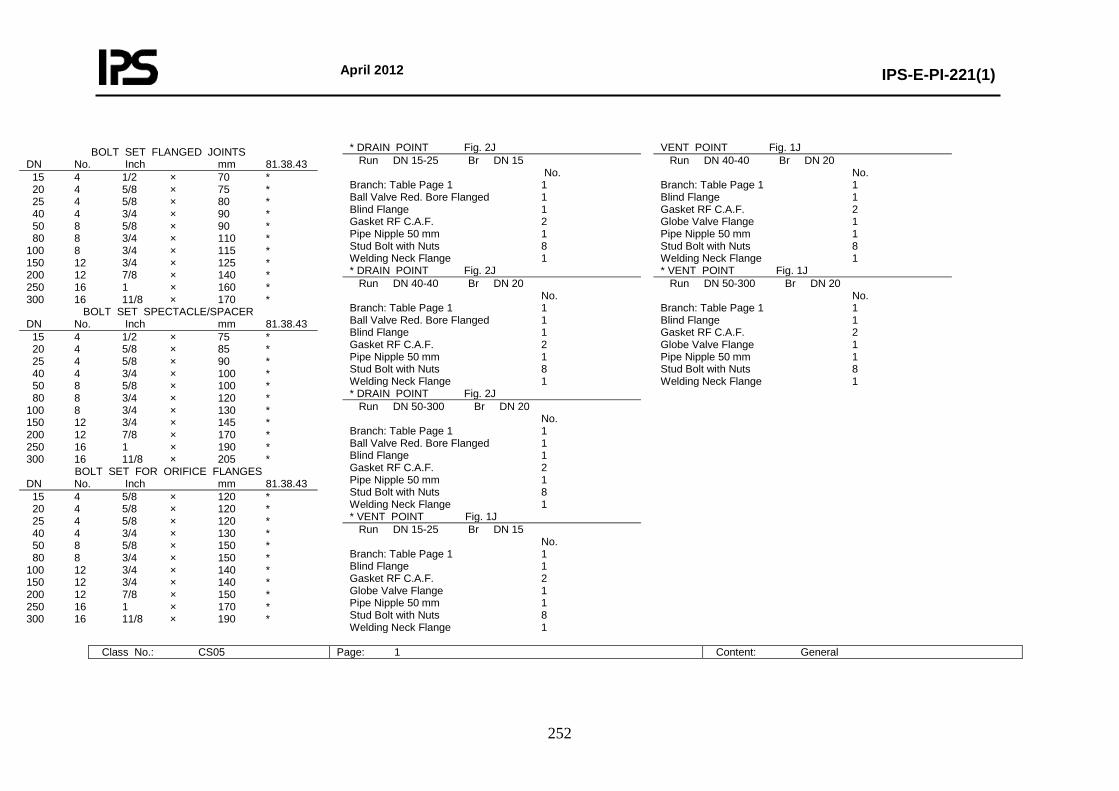
April 2012
IPS-E-PI-221(1)
252
BOLT SET FLANGED JOINTS DN No. Inch mm 81.38.43 15 4 1/2 × 70 * 20 4 5/8 × 75 * 25 4 5/8 × 80 * 40 4 3/4 × 90 * 50 8 5/8 × 90 * 80 8 3/4 × 110 * 100 8 3/4 × 115 * 150 12 3/4 × 125 * 200 12 7/8 × 140 * 250 16 1 × 160 * 300 16 11/8 × 170 *
BOLT SET SPECTACLE/SPACER DN No. Inch mm 81.38.43 15 4 1/2 × 75 * 20 4 5/8 × 85 * 25 4 5/8 × 90 * 40 4 3/4 × 100 * 50 8 5/8 × 100 * 80 8 3/4 × 120 * 100 8 3/4 × 130 * 150 12 3/4 × 145 * 200 12 7/8 × 170 * 250 16 1 × 190 * 300 16 11/8 × 205 *
BOLT SET FOR ORIFICE FLANGES DN No. Inch mm 81.38.43 15 4 5/8 × 120 * 20 4 5/8 × 120 * 25 4 5/8 × 120 * 40 4 3/4 × 130 * 50 8 5/8 × 150 * 80 8 3/4 × 150 * 100 12 3/4 × 140 * 150 12 3/4 × 140 * 200 12 7/8 × 150 * 250 16 1 × 170 * 300 16 11/8 × 190 *
* DRAIN POINT Fig. 2J Run DN 15-25 Br DN 15 No. Branch: Table Page 1 1 Ball Valve Red. Bore Flanged 1 Blind Flange 1 Gasket RF C.A.F. 2 Pipe Nipple 50 mm 1 Stud Bolt with Nuts 8 Welding Neck Flange 1 * DRAIN POINT Fig. 2J Run DN 40-40 Br DN 20 No. Branch: Table Page 1 1 Ball Valve Red. Bore Flanged 1 Blind Flange 1 Gasket RF C.A.F. 2 Pipe Nipple 50 mm 1 Stud Bolt with Nuts 8 Welding Neck Flange 1 * DRAIN POINT Fig. 2J Run DN 50-300 Br DN 20 No. Branch: Table Page 1 1 Ball Valve Red. Bore Flanged 1 Blind Flange 1 Gasket RF C.A.F. 2 Pipe Nipple 50 mm 1 Stud Bolt with Nuts 8 Welding Neck Flange 1 * VENT POINT Fig. 1J Run DN 15-25 Br DN 15 No. Branch: Table Page 1 1 Blind Flange 1 Gasket RF C.A.F. 2 Globe Valve Flange 1 Pipe Nipple 50 mm 1 Stud Bolt with Nuts 8 Welding Neck Flange 1
VENT POINT Fig. 1J Run DN 40-40 Br DN 20 No. Branch: Table Page 1 1 Blind Flange 1 Gasket RF C.A.F. 2 Globe Valve Flange 1 Pipe Nipple 50 mm 1 Stud Bolt with Nuts 8 Welding Neck Flange 1 * VENT POINT Fig. 1J Run DN 50-300 Br DN 20 No. Branch: Table Page 1 1 Blind Flange 1 Gasket RF C.A.F. 2 Globe Valve Flange 1 Pipe Nipple 50 mm 1 Stud Bolt with Nuts 8 Welding Neck Flange 1
Class No.: CS05 Page: 1 Content: General
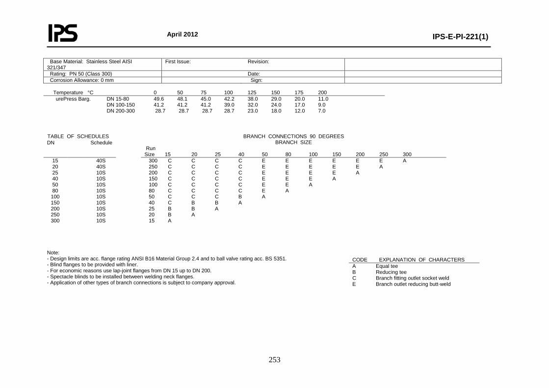
April 2012
IPS-E-PI-221(1)
253
Temperature °C 0 50 75 100 125 150 175 200 urePress Barg.
DN 15-80 49.6 48.1 45.0 42.2 38.0 29.0 20.0 11.0 DN 100-150 41.2 41.2 41.2 39.0 32.0 24.0 17.0 9.0 DN 200-300 28.7 28.7 28.7 28.7 23.0 18.0 12.0 7.0
Note: - Design limits are acc. flange rating ANSI B16 Material Group 2.4 and to ball valve rating acc. BS 5351. - Blind flanges to be provided with liner. - For economic reasons use lap-joint flanges from DN 15 up to DN 200. - Spectacle blinds to be installed between welding neck flanges. - Application of other types of branch connections is subject to company approval.
Base Material: Stainless Steel AISI 321/347
First Issue: Revision:
Rating: PN 50 (Class 300) Date: Corrosion Allowance: 0 mm Sign:
TABLE OF SCHEDULES BRANCH CONNECTIONS 90 DEGREES BRANCH SIZE
Run Size 15 20 25 40 50 80 100 150 200 250 300
DN Schedule
15 20 25 40 50 80
100 150 200 250 300
40S 40S 10S 10S 10S 10S 10S 10S 10S 10S 10S
300 C C C C E E E E E E A 250 C C C C E E E E E A 200 C C C C E E E E A 150 C C C C E E E A 100 C C C C E E A 80 C C C C E A 50 C C C B A 40 C B B A 25 B B A 20 B A 15 A
CODE EXPLANATION OF CHARACTERS A Equal tee B Reducing tee C Branch fitting outlet socket weld E Branch outlet reducing butt-weld

April 2012
IPS-E-PI-221(1)
254
Class No.: CS05 Page: 2 Content: Material Descriptions
* PIPE PIPE Pipe DN 15-300 ASTM A312-TP316L (Seamless or Welded) PNPP Pipe Nipple 50 mm DN 15-40 ASTM A312-TP316L (Seamless) * FLANGES BLFL Blind Flange DN 15-300 ASTM A182-F316 FLIN Blind Flange Liner DN 15-300 ASTM A240-TP316 SBFL Spectacle Blind Flange DN 15-300 ASTM A240-TP316 WNFL Welding Neck Flange DN 15-300 ASTM A182-F316 * FITTINGS CAPB Cap Butt-Weld. End DN 15-300 ASTM A403-WP316L E45B Elbow 45 Deg. Butt-Weld. End DN 15-300 ASTM A403-WP316L E90B Elbow 90 Deg. Butt-Weld. End DN 15-300 ASTM A403-WP316L STUB End DN 15-200 ASTM A403-WP316L TEEB Equal Tee Butt-Weld. End DN 15-300 ASTM A403-WP316L E45S Elbow 45 Deg. Socket-Weld. End DN 15-40 ASTM A182-F316 E90S Elbow 90 Deg. Socket-Weld. End DN 15-40 ASTM A182-F316 TEES Equal Tee Socket-Weld. End DN 15-40 ASTM A182-F316 COUS Coupling Socket-Weld. End DN 15-40 ASTM A182-F316 CAPS Cap Socket-Weld. End DN 15-40 ASTM A182-F316 * REDUCING FITTINGS BROS Branch Fitting Outlet Socket-Weld. End DN 15-40 ASTM A182-F316 BROB Branch Outlet Red. Butt-Weld. DN 50-300 ASTM A182-F316 RECB Reducer Conc. Butt-Weld. End DN 20-300 ASTM A403-WP316L REEB Reducer Ecc. Butt-Weld. End DN 20-300 ASTM A403-WP316L TERB Tee Reducing Butt-Weld. End DN 20-50 ASTM A403-WP316L TERS Tee Reducing Socket-Weld. End DN 20-40 ASTM A182-F316 Note: - For full material description see relevant buying description. - Where both socket weld and butt weld fittings are specified, preference is subject to company approval.
* VALVES BARF Ball Valve Red. Bore Flanged DN 15-250 Body: ASTM A351-CF8M, A182-F316 Int: AISI 316 (L)/ PTFE GHVF Check Valve Flanged DN 15-300 Body: ASTM A351-CF8M, A182-F316 Trim: AISI 316 (L) + Stellite 6 Seat: PTFE, FKM GAVF Gate Valve Flanged DN 50-300 Body: ASTM A351-CF8M, A182-F316 Trim: AISI 316 (L) + Stellite 6 GLBF Globe Valve Flanged DN 15-200 Body: ASTM A351-CF8M, A182-F316 Trim: AISI 316 (L) + Stellite 6 * MISCELLANEOUS GKSW Gasket, Spiral Wound DN 15-300 AISI 316, 316L Graphite Filled CS Centring-, SS Inner-Ring. ORFS Orifice Flange Set DN 50-300 ASTM A182-F316 STBT Stud Bolt with Nuts ---- Studs: ASTM A193-B7 Nuts: ASTM A194-2H
Class No.: CS05 Page: 3 Content: Piping Components
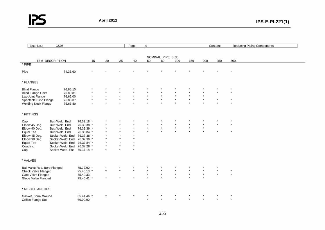
April 2012
IPS-E-PI-221(1)
255
lass No.: CS05 Page: 4 Content: Reducing Piping Components
NOMINAL PIPE SIZE ITEM DESCRIPTION 15 20 25 40 50 80 100 150 200 250 300 * PIPE Pipe 74.36.60 * * * * * * * * * * * * FLANGES Blind Flange 76.65.10 * * * * * * * * * * * Blind Flange Liner 76.80.81 * * * * * * * * * * * Lap-Joint Flange 76.62.00 * * * * * * * * * Spectacle Blind Flange 76.88.07 * * * * * * * * * * * Welding Neck Flange 76.65.80 * * * * * * * * * * * * FITTINGS Cap Butt-Weld. End 76.33.18 * * * * * * * * * * * Elbow 45 Deg. Butt-Weld. End 76.33.38 * * * * * * * * * * * Elbow 90 Deg. Butt-Weld. End 76.33.39 * * * * * * * * * Equal Tee Butt-Weld. End 76.33.84 * * * * * * * * * * * Elbow 45 Deg. Socket-Weld. End 76.37.38 * * * * Elbow 90 Deg. Socket-Weld. End 76.37.39 * * * * Equal Tee Socket-Weld. End 76.37.84 * * * * Coupling Socket-Weld. End 76.37.28 * * * * Cap Socket-Weld. End 76.37.18 * * * * * VALVES Ball Valve Red. Bore Flanged 75.72.00 * * * * * * * * * * Check Valve Flanged 75.40.13 * * * * * * * * * * * Gate Valve Flanged 75.40.33 * * * * * * * Globe Valve Flanged 75.40.41 * * * * * * * * * * MISCELLANEOUS Gasket, Spiral Wound 85.41.46 * * * * * * * * * * * Orifice Flange Set 60.00.00 * * * * * * *
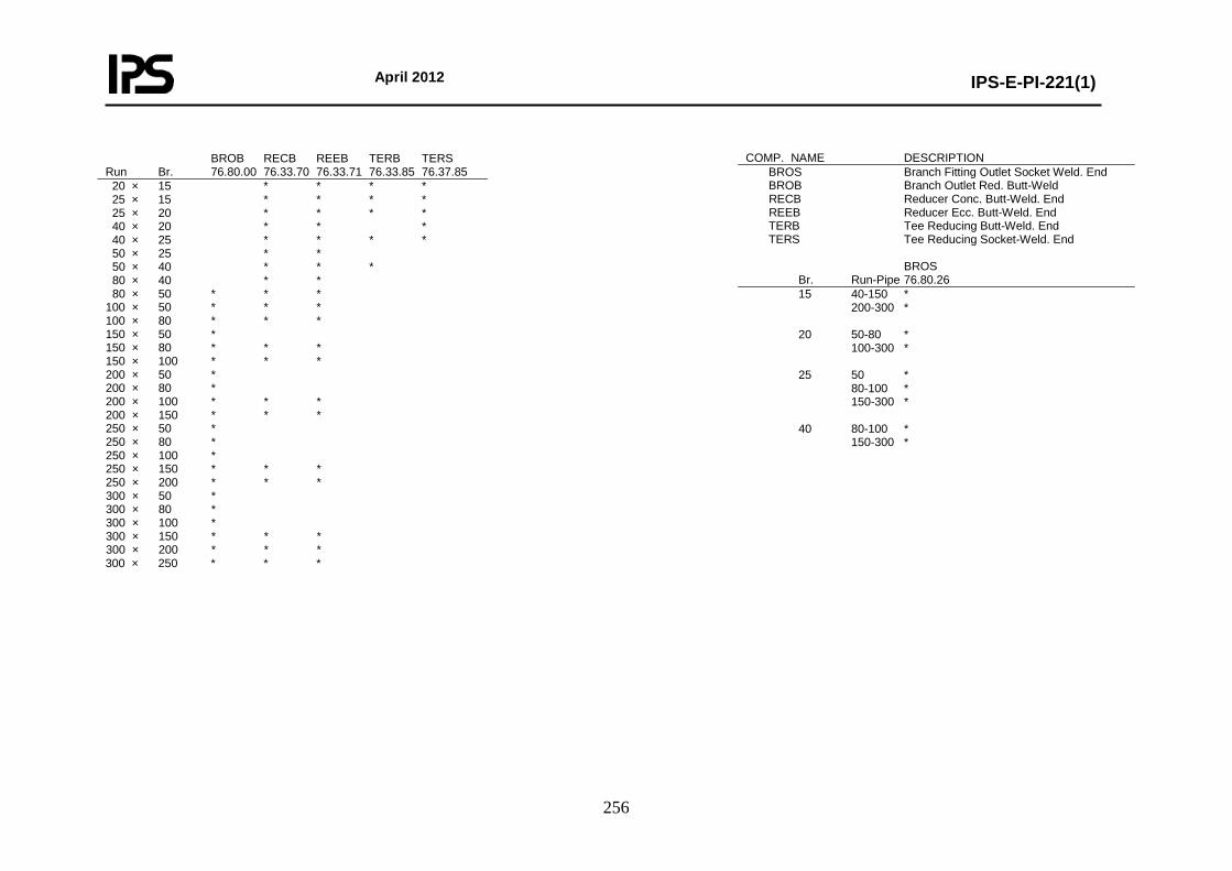
April 2012
IPS-E-PI-221(1)
256
BROB RECB REEB TERB TERS Run Br. 76.80.00 76.33.70 76.33.71 76.33.85 76.37.85 20 × 15 * * * * 25 × 15 * * * * 25 × 20 * * * * 40 × 20 * * * 40 × 25 * * * * 50 × 25 * * 50 × 40 * * * 80 × 40 * * 80 × 50 * * * 100 × 50 * * * 100 × 80 * * * 150 × 50 * 150 × 80 * * * 150 × 100 * * * 200 × 50 * 200 × 80 * 200 × 100 * * * 200 × 150 * * * 250 × 50 * 250 × 80 * 250 × 100 * 250 × 150 * * * 250 × 200 * * * 300 × 50 * 300 × 80 * 300 × 100 * 300 × 150 * * * 300 × 200 * * * 300 × 250 * * *
COMP. NAME DESCRIPTION BROS Branch Fitting Outlet Socket Weld. End BROB Branch Outlet Red. Butt-Weld RECB Reducer Conc. Butt-Weld. End REEB Reducer Ecc. Butt-Weld. End TERB Tee Reducing Butt-Weld. End TERS Tee Reducing Socket-Weld. End BROS Br. Run-Pipe 76.80.26 15 40-150 * 200-300 * 20 50-80 * 100-300 * 25 50 * 80-100 * 150-300 * 40 80-100 * 150-300 *

April 2012
IPS-E-PI-221(1)
257
Class No.: CS05 Page: 5 Content: Bolting and Assemblies
BOLT SET FLANGED JOINTS DN No. Inch mm 81.38.61 15 4 1/2 × 70 * 20 4 5/8 × 75 * 25 4 5/8 × 80 * 40 4 3/4 × 90 * 50 8 5/8 × 90 * 80 8 3/4 × 110 * 100 8 3/4 × 115 * 150 12 3/4 × 125 * 200 12 7/8 × 140 * 250 16 1 × 160 * 300 16 11/8 × 170 *
BOLT SET SPECTACLE/SPACER DN No. Inch mm 81.38.61 15 4 1/2 × 75 * 20 4 5/8 × 85 * 25 4 5/8 × 90 * 40 4 3/4 × 100 * 50 8 5/8 × 100 * 80 8 3/4 × 120 * 100 8 3/4 × 130 * 150 12 3/4 × 145 * 200 12 7/8 × 170 * 250 16 1 × 190 * 300 16 11/8 × 205 *
BOLT SET FOR ORIFICE FLANGES DN No. Inch mm 81.38.61 15 4 5/8 × 120 * 20 4 5/8 × 120 * 25 4 5/8 × 120 * 40 4 3/4 × 130 * 50 8 5/8 × 150 * 80 8 3/4 × 150 * 100 12 3/4 × 140 * 150 12 3/4 × 140 * 200 12 7/8 × 150 * 250 16 1 × 170 * 300 16 11/8 × 190 *
* DRAIN POINT Fig. 2I Run DN 15-25 Br DN 15 No. Branch: Table Page 1 1 Ball Valve Red. Bore Flanged 1 Blind Flange 1 Gasket Spiral Wound 2 Stud Bolt with Nuts 8 Welding Neck Flange 1 * DRAIN POINT Fig. 2I Run DN 40-40 Br DN 20 No. Branch: Table Page 1 1 Ball Valve Red. Bore Flanged 1 Blind Flange 1 Gasket Spiral Wound 2 Stud Bolt with Nuts 8 Welding Neck Flange 1 * DRAIN POINT Fig. 2J Run DN 50-300 Br DN 20 No. Branch: Table Page 1 1 Ball Valve Red. Bore Flanged 1 Blind Flange 1 Gasket Spiral Wound 2 Pipe Nipple 50 mm 1 Stud Bolt with Nuts 8 Welding Neck Flange 1 * VENT POINT Fig. 1I Run DN 15-25 Br DN 15 No. Branch: Table Page 1 1 Blind Flange 1 Gasket Spiral Wound 2 Globe Valve Flange Bellows Seal 1 Stud Bolt with Nuts 8 Welding Neck Flange 1
* VENT POINT Fig. 1I Run DN 40-40 Br DN 20 No. Branch: Table Page 1 1 Blind Flange 1 Gasket Spiral Wound 2 Globe Valve Flange Bellows Seal 1 Stud Bolt with Nuts 8 Welding Neck Flange 1 * VENT POINT Fig. 1I Run DN 50-300 Br DN 20 No. Branch: Table Page 1 1 Blind Flange 1 Gasket Spiral Wound 2 Globe Valve Flange Bellows Seal 1 Pipe Nipple 50 mm 1 Stud Bolt with Nuts 8 Welding Neck Flange 1
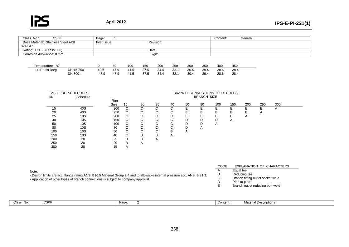
April 2012
IPS-E-PI-221(1)
258
Temperature °C 0 50 100 150 200 250 300 350 400 450 urePress Barg.
DN 15-250 49.6 47.9 41.5 37.5 34.4 32.1 30.4 29.4 28.6 28.4 DN 300- 47.9 47.9 41.5 37.5 34.4 32.1 30.4 29.4 28.6 28.4
Note: - Design limits are acc. flange rating ANSI B16.5 Material Group 2.4 and to allowable internal pressure acc. ANSI B 31.3. - Application of other types of branch connections is subject to company approval.
Class No.: CS06 Page: 2 Content: Material Descriptions
Class No.: CS06 Page: 1 Content: General Base Material: Stainless Steel AISI 321/347
First Issue: Revision:
Rating: PN 50 (Class 300) Date: Corrosion Allowance: 0 mm Sign:
TABLE OF SCHEDULES BRANCH CONNECTIONS 90 DEGREES BRANCH SIZE
Run Size 15 20 25 40 50 80 100 150 200 250 300
DN Schedule
15 20 25 40 50 80
100 150 200 250 300
40S 40S 10S 10S 10S 10S 10S 10S 20 20 20
300 C C C C E E E E E E A 250 C C C C E E E E E A 200 C C C C E E E E A 150 C C C C D D D A 100 C C C C D D A 80 C C C C D A 50 C C C B A 40 C B B A 25 B B A 20 B A 15 A
CODE EXPLANATION OF CHARACTERS A Equal tee B Reducing tee C Branch fitting outlet socket weld D Pipe to pipe E Branch outlet reducing butt-weld
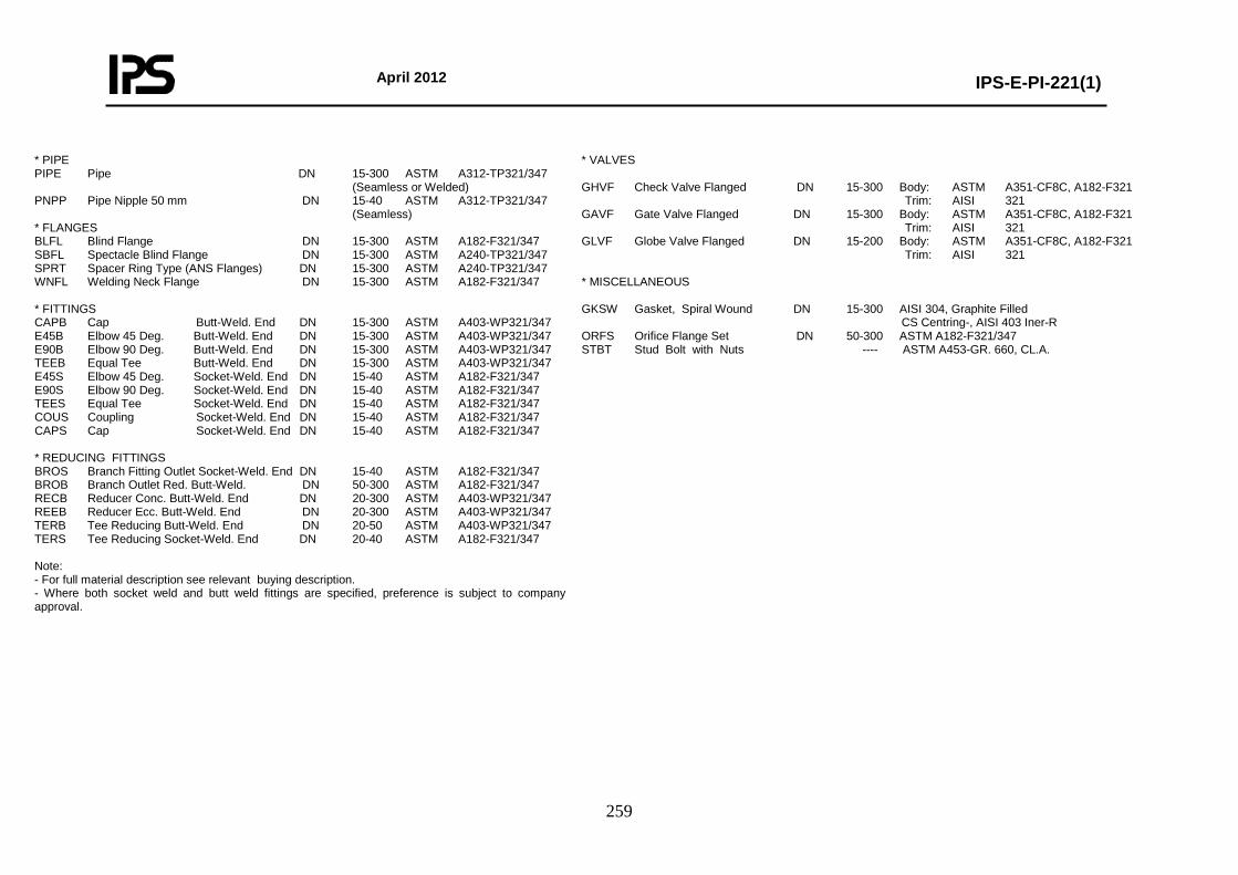
April 2012
IPS-E-PI-221(1)
259
* PIPE PIPE Pipe DN 15-300 ASTM A312-TP321/347 (Seamless or Welded) PNPP Pipe Nipple 50 mm DN 15-40 ASTM A312-TP321/347 (Seamless) * FLANGES BLFL Blind Flange DN 15-300 ASTM A182-F321/347 SBFL Spectacle Blind Flange DN 15-300 ASTM A240-TP321/347 SPRT Spacer Ring Type (ANS Flanges) DN 15-300 ASTM A240-TP321/347 WNFL Welding Neck Flange DN 15-300 ASTM A182-F321/347 * FITTINGS CAPB Cap Butt-Weld. End DN 15-300 ASTM A403-WP321/347 E45B Elbow 45 Deg. Butt-Weld. End DN 15-300 ASTM A403-WP321/347 E90B Elbow 90 Deg. Butt-Weld. End DN 15-300 ASTM A403-WP321/347 TEEB Equal Tee Butt-Weld. End DN 15-300 ASTM A403-WP321/347 E45S Elbow 45 Deg. Socket-Weld. End DN 15-40 ASTM A182-F321/347 E90S Elbow 90 Deg. Socket-Weld. End DN 15-40 ASTM A182-F321/347 TEES Equal Tee Socket-Weld. End DN 15-40 ASTM A182-F321/347 COUS Coupling Socket-Weld. End DN 15-40 ASTM A182-F321/347 CAPS Cap Socket-Weld. End DN 15-40 ASTM A182-F321/347 * REDUCING FITTINGS BROS Branch Fitting Outlet Socket-Weld. End DN 15-40 ASTM A182-F321/347 BROB Branch Outlet Red. Butt-Weld. DN 50-300 ASTM A182-F321/347 RECB Reducer Conc. Butt-Weld. End DN 20-300 ASTM A403-WP321/347 REEB Reducer Ecc. Butt-Weld. End DN 20-300 ASTM A403-WP321/347 TERB Tee Reducing Butt-Weld. End DN 20-50 ASTM A403-WP321/347 TERS Tee Reducing Socket-Weld. End DN 20-40 ASTM A182-F321/347 Note: - For full material description see relevant buying description. - Where both socket weld and butt weld fittings are specified, preference is subject to company approval.
* VALVES GHVF Check Valve Flanged DN 15-300 Body: ASTM A351-CF8C, A182-F321 Trim: AISI 321 GAVF Gate Valve Flanged DN 15-300 Body: ASTM A351-CF8C, A182-F321 Trim: AISI 321 GLVF Globe Valve Flanged DN 15-200 Body: ASTM A351-CF8C, A182-F321 Trim: AISI 321 * MISCELLANEOUS GKSW Gasket, Spiral Wound DN 15-300 AISI 304, Graphite Filled CS Centring-, AISI 403 Iner-R ORFS Orifice Flange Set DN 50-300 ASTM A182-F321/347 STBT Stud Bolt with Nuts ---- ASTM A453-GR. 660, CL.A.
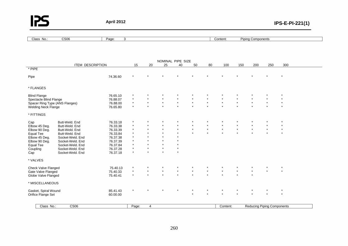
April 2012
IPS-E-PI-221(1)
260
Class No.: CS06 Page: 3 Content: Piping Components
Class No.: CS06 Page: 4 Content: Reducing Piping Components
NOMINAL PIPE SIZE ITEM DESCRIPTION 15 20 25 40 50 80 100 150 200 250 300
* PIPE Pipe 74.36.60 * * * * * * * * * * * * FLANGES Blind Flange 76.65.10 * * * * * * * * * * * Spectacle Blind Flange 76.88.07 * * * * * * * * * * * Spacer Ring Type (ANS Flanges) 76.88.00 * * * * * * * * * * * Welding Neck Flange 76.65.80 * * * * * * * * * * * * FITTINGS Cap Butt-Weld. End 76.33.18 * * * * * * * * * * * Elbow 45 Deg. Butt-Weld. End 76.33.38 * * * * * * * * * * * Elbow 90 Deg. Butt-Weld. End 76.33.39 * * * * * * * * * * * Equal Tee Butt-Weld. End 76.33.84 * * * * * * * * * * * Elbow 45 Deg. Socket-Weld. End 76.37.38 * * * * Elbow 90 Deg. Socket-Weld. End 76.37.39 * * * * Equal Tee Socket-Weld. End 76.37.84 * * * * Coupling Socket-Weld. End 76.37.28 * * * * Cap Socket-Weld. End 76.37.18 * * * * * VALVES Check Valve Flanged 75.40.13 * * * * * * * * * * * Gate Valve Flanged 75.40.33 * * * * * * * * * * * Globe Valve Flanged 75.40.41 * * * * * * * * * * MISCELLANEOUS Gasket, Spiral Wound 85.41.43 * * * * * * * * * * * Orifice Flange Set 60.00.00 * * * * * * *

April 2012
IPS-E-PI-221(1)
261
Class No.: CS06 Page: 5 Content: Bolting and Assemblies
BROB RECB REEB TERB TERS Run Br. 76.80.00 76.33.70 76.33.71 76.33.85 76.37.85 20 × 15 * * * * 25 × 15 * * * * 25 × 20 * * * * 40 × 15 * * 40 × 20 * * * * 40 × 25 * * * * 50 × 25 * * 50 × 40 * * * 80 × 40 * * 80 × 50 * * * 100 × 50 * * * 100 × 80 * * * 150 × 50 * 150 × 80 * * * 150 × 100 * * * 200 × 50 * 200 × 80 * 200 × 100 * 200 × 150 * * 250 × 50 * 250 × 80 * 250 × 100 * 250 × 150 * * 250 × 200 * * * 300 × 50 * 300 × 80 * 300 × 100 * 300 × 150 * 300 × 200 * * * 300 × 250 * * *
COMP. NAME DESCRIPTION BROS Branch Fitting Outlet Socket Weld. End BROB Branch Outlet Red. Butt-Weld RECB Reducer Conc. Butt-Weld. End REEB Reducer Ecc. Butt-Weld. End TERB Tee Reducing Butt-Weld. End TERS Tee Reducing Socket-Weld. End BROS Br. Run-Pipe 76.80.26 15 40-150 * 200-300 * 20 50-80 * 100-300 * 25 50 * 80-100 * 150-300 * 40 80-100 * 150-300 *
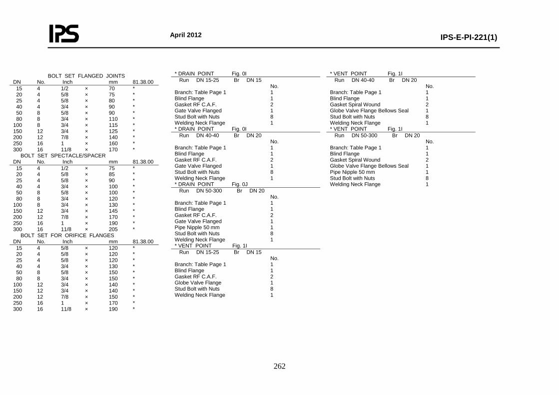
April 2012
IPS-E-PI-221(1)
262
BOLT SET FLANGED JOINTS DN No. Inch mm 81.38.00 15 4 1/2 × 70 * 20 4 5/8 × 75 * 25 4 5/8 × 80 * 40 4 3/4 × 90 * 50 8 5/8 × 90 * 80 8 3/4 × 110 * 100 8 3/4 × 115 * 150 12 3/4 × 125 * 200 12 7/8 × 140 * 250 16 1 × 160 * 300 16 11/8 × 170 * BOLT SET SPECTACLE/SPACER DN No. Inch mm 81.38.00 15 4 1/2 × 75 * 20 4 5/8 × 85 * 25 4 5/8 × 90 * 40 4 3/4 × 100 * 50 8 5/8 × 100 * 80 8 3/4 × 120 * 100 8 3/4 × 130 * 150 12 3/4 × 145 * 200 12 7/8 × 170 * 250 16 1 × 190 * 300 16 11/8 × 205 * BOLT SET FOR ORIFICE FLANGES DN No. Inch mm 81.38.00 15 4 5/8 × 120 * 20 4 5/8 × 120 * 25 4 5/8 × 120 * 40 4 3/4 × 130 * 50 8 5/8 × 150 * 80 8 3/4 × 150 * 100 12 3/4 × 140 * 150 12 3/4 × 140 * 200 12 7/8 × 150 * 250 16 1 × 170 * 300 16 11/8 × 190 *
* DRAIN POINT Fig. 0I Run DN 15-25 Br DN 15 No. Branch: Table Page 1 1 Blind Flange 1 Gasket RF C.A.F. 2 Gate Valve Flanged 1 Stud Bolt with Nuts 8 Welding Neck Flange 1 * DRAIN POINT Fig. 0I Run DN 40-40 Br DN 20 No. Branch: Table Page 1 1 Blind Flange 1 Gasket RF C.A.F. 2 Gate Valve Flanged 1 Stud Bolt with Nuts 8 Welding Neck Flange 1 * DRAIN POINT Fig. 0J Run DN 50-300 Br DN 20 No. Branch: Table Page 1 1 Blind Flange 1 Gasket RF C.A.F. 2 Gate Valve Flanged 1 Pipe Nipple 50 mm 1 Stud Bolt with Nuts 8 Welding Neck Flange 1 * VENT POINT Fig. 1I Run DN 15-25 Br DN 15 No. Branch: Table Page 1 1 Blind Flange 1 Gasket RF C.A.F. 2 Globe Valve Flange 1 Stud Bolt with Nuts 8 Welding Neck Flange 1
* VENT POINT Fig. 1I Run DN 40-40 Br DN 20 No. Branch: Table Page 1 1 Blind Flange 1 Gasket Spiral Wound 2 Globe Valve Flange Bellows Seal 1 Stud Bolt with Nuts 8 Welding Neck Flange 1 * VENT POINT Fig. 1I Run DN 50-300 Br DN 20 No. Branch: Table Page 1 1 Blind Flange 1 Gasket Spiral Wound 2 Globe Valve Flange Bellows Seal 1 Pipe Nipple 50 mm 1 Stud Bolt with Nuts 8 Welding Neck Flange 1
April 2012
IPS-E-PI-221(1)
263
Temperature °C 0 50 100 150 200 300 400 450 500 538 urePress Barg.
DN 15-250 49.6 47.9 41.5 37.5 34.4 30.4 28.6 28.3 27.0 24.4 DN 300- 47.9 47.9 41.5 37.5 34.4 30.4 28.6 28.3 27.0 24.4
Note: - Design limits are acc. flange rating ANSI B16.5 Material Group 2.4 and to allowable internal pressure acc. ANSI B 31.3. - Cold bending of pipe is not allowed and hot bending is not recommended. - Application of other types of branch connections is subject to company approval.
Class No.: CS07 Page: 1 Content: General Base Material: Stainless Steel AISI 321, Stab. HT
First Issue: Revision:
Rating: PN 50 (Class 300) Date: Corrosion Allowance: 0 mm Sign:
TABLE OF SCHEDULES BRANCH CONNECTIONS 90 DEGREES BRANCH SIZE
Run Size 15 20 25 40 50 80 100 150 200 250 300
DN Schedule
15 20 25 40 50 80
100 150 200 250 300
40S 40S 40S 40S 40S 40S 40S 40S 20 20 20
300 C C C C E E E B B B A 250 C C C C E E E B B A 200 C C C C E E B B A 150 C C C C E B B A 100 C C C C B B A 80 C C C B B A 50 C C C B A 40 C B B A 25 B B A 20 B A 15 A
CODE EXPLANATION OF CHARACTERS A Equal tee B Reducing tee C Branch fitting outlet socket weld E Branch outlet reducing butt-weld

April 2012
IPS-E-PI-221(1)
264
Class No.: CS07 Page: 2 Content: Material Descriptions
* PIPE PIPE Pipe DN 15-300 ASTM A312-TP321 STAB. HT. (Seamless or Welded) PNPP Pipe Nipple 50 mm DN 15-40 ASTM A312-TP321 STAB. HT. (Seamless) * FLANGES BLFL Blind Flange DN 15-300 ASTM A182-F321 STAB. HT. SBFL Spectacle Blind Flange DN 15-300 ASTM A240-TP321 STAB. HT. SPRT Spacer Ring Type (ANS Flanges) DN 15-300 ASTM A240-TP321 STAB. HT. WNFL Welding Neck Flange-Smooth Finish DN 15-300 ASTM A182-F321 STAB. HT. * FITTINGS CAPB Cap Butt-Weld. End DN 15-300 ASTM A403-WP-S-321 STAB. HT. E45B Elbow 45 Deg. Butt-Weld. End DN 15-300 ASTM A403-WP-S-321 STAB. HT. E90B Elbow 90 Deg. Butt-Weld. End DN 15-300 ASTM A403-WP-S-321 STAB. HT. TEEB Equal Tee Butt-Weld. End DN 15-300 ASTM A403-WP-S-321 STAB. HT. E45S Elbow 45 Deg. Socket-WeldEnd DN 15-40 ASTM A182-F321 STAB. HT. E90S Elbow 90 Deg. Socket-Weld.End DN 15-40 ASTM A182-F321 STAB. HT. TEES Equal Tee Socket-Weld. End DN 15-40 ASTM A182-F321 STAB. HT. COUS Coupling Socket-Weld. End DN 15-40 ASTM A182-F321 STAB. HT. CAPS Cap Socket-Weld. End DN 15-40 ASTM A182-F321 STAB. HT. * REDUCING FITTINGS BROS Branch Fitting Outlet Socket-Weld. End DN 15-40 ASTM A182-F321 STAB. HT. BROB Branch Outlet Red. Butt-Weld. DN 50-300 ASTM A182-F321 STAB. HT. RECB Reducer Conc. Butt-Weld. End DN 20-300 ASTM A403-WP-S-321 STAB. HT. REEB Reducer Ecc. Butt-Weld. End DN 20-300 ASTM A403-WP-S-321 STAB. HT. TERB Tee Reducing Butt-Weld. End DN 20-300 ASTM A403-WP-S-321 STAB. HT. TERS Tee Reducing Socket-Weld. End DN 20-40 ASTM A182-F321 STAB. HT. Note: - For full material description see relevant buying description. - Where both socket weld and butt weld fittings are specified, preference is subject to company approval.
* VALVES GHVF Check Valve Flanged DN 15-300 Body: ASTM A351-CF8C, A182-F321 Trim: AISI 321 + Stellite 6 GAVF Gate Valve Flanged DN 15-300 Body: ASTM A351-CF8C, A182-F321 Trim: AISI 321 + Stellite 6 GLVF Globe Valve Flanged DN 15-200 Body: ASTM A351-CF8C, A182-F321 Trim: AISI 321 + Stellite 6 * MISCELLANEOUS GKTI Gasket, Spiral Wound DN 15-300 AISI 316L Graphite Filled ORFS Orifice Flange Set DN 50-300 ASTM A182-F321 STAB. HT. STBT Stud Bolt with Nuts --- ASTM A453-GR. 660, CL.A.
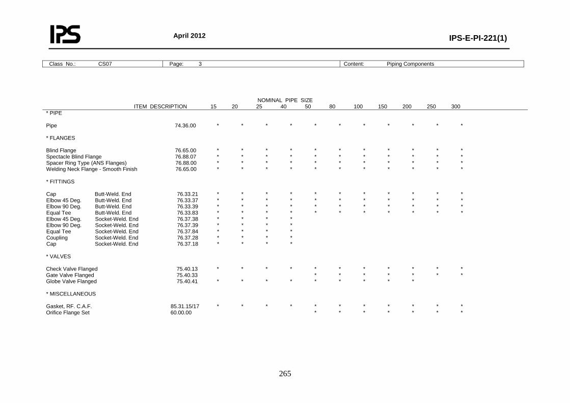
April 2012
IPS-E-PI-221(1)
265
Class No.: CS07 Page: 3 Content: Piping Components
NOMINAL PIPE SIZE ITEM DESCRIPTION 15 20 25 40 50 80 100 150 200 250 300
* PIPE Pipe 74.36.00 * * * * * * * * * * * * FLANGES Blind Flange 76.65.00 * * * * * * * * * * * Spectacle Blind Flange 76.88.07 * * * * * * * * * * * Spacer Ring Type (ANS Flanges) 76.88.00 * * * * * * * * * * * Welding Neck Flange - Smooth Finish 76.65.00 * * * * * * * * * * * * FITTINGS Cap Butt-Weld. End 76.33.21 * * * * * * * * * * * Elbow 45 Deg. Butt-Weld. End 76.33.37 * * * * * * * * * * * Elbow 90 Deg. Butt-Weld. End 76.33.39 * * * * * * * * * * * Equal Tee Butt-Weld. End 76.33.83 * * * * * * * * * * * Elbow 45 Deg. Socket-Weld. End 76.37.38 * * * * Elbow 90 Deg. Socket-Weld. End 76.37.39 * * * * Equal Tee Socket-Weld. End 76.37.84 * * * * Coupling Socket-Weld. End 76.37.28 * * * * Cap Socket-Weld. End 76.37.18 * * * * * VALVES Check Valve Flanged 75.40.13 * * * * * * * * * * * Gate Valve Flanged 75.40.33 * * * * * * * Globe Valve Flanged 75.40.41 * * * * * * * * * * MISCELLANEOUS Gasket, RF. C.A.F. 85.31.15/17 * * * * * * * * * * * Orifice Flange Set 60.00.00 * * * * * * *

April 2012
IPS-E-PI-221(1)
266
Class No.: CS07 Page: 4 Content: Reducing Piping Components
Class No.: CS07 Page: 5 Content: Bolting and Assemblies
COMP. NAME DESCRIPTION BROS Branch Fitting Outlet Socket Weld. End BROB Branch Outlet Red. Butt-Weld RECB Reducer Conc. Butt-Weld. End REEB Reducer Ecc. Butt-Weld. End TERB Tee Reducing Butt-Weld. End TERS Tee Reducing Socket-Weld. End BROS Br. Run-Pipe 76.80.26 15 40-150 * 200-300 * 20 50-80 * 100-300 * 25 50 * 80-100 * 150-300 * 40 80-100 * 150-300 *
BROB RECB REEB TERB TERS Run Br. 76.80.00 76.33.70 76.33.71 76.33.85 76.37.85 20 × 15 * * * * 25 × 15 * * * * 25 × 20 * * * * 40 × 15 * * 40 × 20 * * * * 40 × 25 * * * * 50 × 25 * * 50 × 40 * * * 80 × 40 * * 80 × 50 * * * * 100 × 50 * * * * 100 × 80 * * * * 150 × 50 * 150 × 80 * * * * 150 × 100 * * * * 200 × 50 * 200 × 80 * 200 × 100 * * * * 200 × 150 * * * * 250 × 50 * 250 × 80 * 250 × 100 * * 250 × 150 * * * * 250 × 200 * * * * 300 × 50 * 300 × 80 * 300 × 100 * 300 × 150 * * * * 300 × 200 * * * * 300 × 250 * * * *
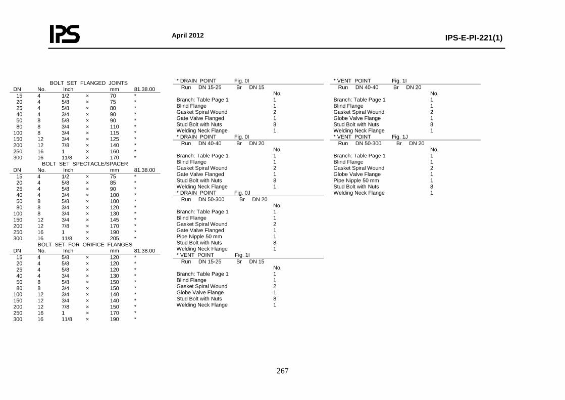
April 2012
IPS-E-PI-221(1)
267
BOLT SET FLANGED JOINTS DN No. Inch mm 81.38.00 15 4 1/2 × 70 * 20 4 5/8 × 75 * 25 4 5/8 × 80 * 40 4 3/4 × 90 * 50 8 5/8 × 90 * 80 8 3/4 × 110 * 100 8 3/4 × 115 * 150 12 3/4 × 125 * 200 12 7/8 × 140 * 250 16 1 × 160 * 300 16 11/8 × 170 *
BOLT SET SPECTACLE/SPACER DN No. Inch mm 81.38.00 15 4 1/2 × 75 * 20 4 5/8 × 85 * 25 4 5/8 × 90 * 40 4 3/4 × 100 * 50 8 5/8 × 100 * 80 8 3/4 × 120 * 100 8 3/4 × 130 * 150 12 3/4 × 145 * 200 12 7/8 × 170 * 250 16 1 × 190 * 300 16 11/8 × 205 *
BOLT SET FOR ORIFICE FLANGES DN No. Inch mm 81.38.00 15 4 5/8 × 120 * 20 4 5/8 × 120 * 25 4 5/8 × 120 * 40 4 3/4 × 130 * 50 8 5/8 × 150 * 80 8 3/4 × 150 * 100 12 3/4 × 140 * 150 12 3/4 × 140 * 200 12 7/8 × 150 * 250 16 1 × 170 * 300 16 11/8 × 190 *
* DRAIN POINT Fig. 0I Run DN 15-25 Br DN 15 No. Branch: Table Page 1 1 Blind Flange 1 Gasket Spiral Wound 2 Gate Valve Flanged 1 Stud Bolt with Nuts 8 Welding Neck Flange 1 * DRAIN POINT Fig. 0I Run DN 40-40 Br DN 20 No. Branch: Table Page 1 1 Blind Flange 1 Gasket Spiral Wound 2 Gate Valve Flanged 1 Stud Bolt with Nuts 8 Welding Neck Flange 1 * DRAIN POINT Fig. 0J Run DN 50-300 Br DN 20 No. Branch: Table Page 1 1 Blind Flange 1 Gasket Spiral Wound 2 Gate Valve Flanged 1 Pipe Nipple 50 mm 1 Stud Bolt with Nuts 8 Welding Neck Flange 1 * VENT POINT Fig. 1I Run DN 15-25 Br DN 15 No. Branch: Table Page 1 1 Blind Flange 1 Gasket Spiral Wound 2 Globe Valve Flange 1 Stud Bolt with Nuts 8 Welding Neck Flange 1
* VENT POINT Fig. 1I Run DN 40-40 Br DN 20 No. Branch: Table Page 1 1 Blind Flange 1 Gasket Spiral Wound 2 Globe Valve Flange 1 Stud Bolt with Nuts 8 Welding Neck Flange 1 * VENT POINT Fig. 1J Run DN 50-300 Br DN 20 No. Branch: Table Page 1 1 Blind Flange 1 Gasket Spiral Wound 2 Globe Valve Flange 1 Pipe Nipple 50 mm 1 Stud Bolt with Nuts 8 Welding Neck Flange 1
April 2012
IPS-E-PI-221(1)
268
PART THREE 0. INTRODUCTION This Standards is prepared in three parts, which are separately bindered as follow:
Part I General (guidance on the application of piping classes). Part II Piping class rating: PN 20 (150) and PN 50 (300). Part III Piping class rating: PN 100 (600), PN 150 (900), PN 250 (1500) and PN 420 (2500).
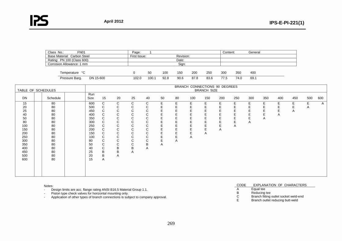
April 2012
IPS-E-PI-221(1)
269
Class No.: FN01 Page: 1 Content: General Base Material: Carbon Steel First Issue: Revision: Rating: PN 100 (Class 600) Date: Corrosion Allowance: 1 mm Sign:
Temperature °C 0 50 100 150 200 250 300 350 400 Pressure Barg. DN 15-600 102.0 100.1 92.8 90.6 87.8 83.6 77.5 74.0 69.1
TABLE OF SCHEDULES
BRANCH CONNECTIONS 90 DEGREES BRANCH SIZE
DN
Schedule
Run Size 15 20 25 40 50 80 100 150 200 250 300 350 400 450 500 600
15 20 25 40 50 80
100 150 200 250 300 350 400 450 500 600
80 80 80 80 80 80 80 80 80 80 80 80 80 80 80 80
600 C C C C E E E E E E E E E E E A 500 C C C C E E E E E E E E E E A 450 C C C C E E E E E E E E E A 400 C C C C E E E E E E E E A 350 C C C C E E E E E E E A 300 C C C C E E E E E E A 250 C C C C E E E E E A 200 C C C C E E E E A 150 C C C C E E E A 100 C C C C E E A 80 C C C C E A 50 C C C B A 40 C B B A 25 B B A 20 B A 15 A
Notes: - Design limits are acc. flange rating ANSI B16.5 Material Group 1.1. - Piston type check valves for horizontal mounting only. - Application of other types of branch connections is subject to company approval.
CODE EXPLANATION OF CHARACTERS A Equal tee B Reducing tee C Branch fitting outlet socket weld-end E Branch outlet reducing butt-weld
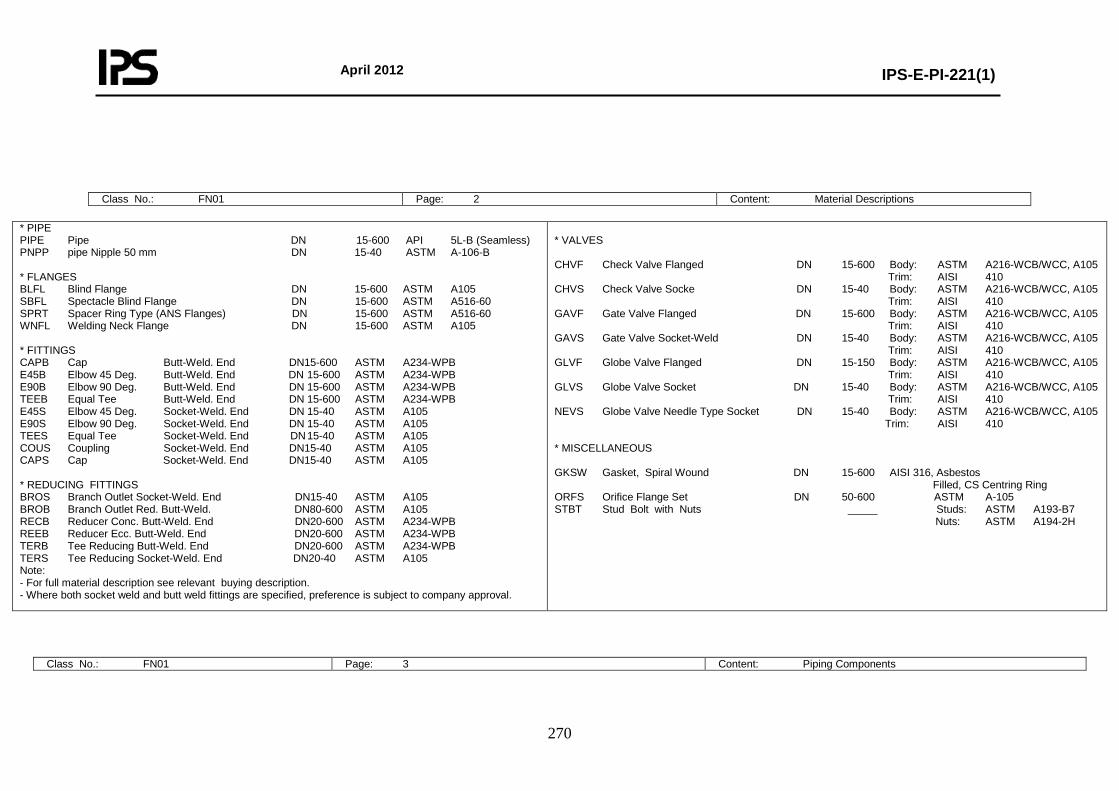
April 2012
IPS-E-PI-221(1)
270
Class No.: FN01 Page: 2 Content: Material Descriptions
* PIPE PIPE Pipe DN 15-600 API 5L-B (Seamless) PNPP pipe Nipple 50 mm DN 15-40 ASTM A-106-B * FLANGES BLFL Blind Flange DN 15-600 ASTM A105 SBFL Spectacle Blind Flange DN 15-600 ASTM A516-60 SPRT Spacer Ring Type (ANS Flanges) DN 15-600 ASTM A516-60 WNFL Welding Neck Flange DN 15-600 ASTM A105 * FITTINGS CAPB Cap Butt-Weld. End DN15-600 ASTM A234-WPB E45B Elbow 45 Deg. Butt-Weld. End DN 15-600 ASTM A234-WPB E90B Elbow 90 Deg. Butt-Weld. End DN 15-600 ASTM A234-WPB TEEB Equal Tee Butt-Weld. End DN 15-600 ASTM A234-WPB E45S Elbow 45 Deg. Socket-Weld. End DN 15-40 ASTM A105 E90S Elbow 90 Deg. Socket-Weld. End DN 15-40 ASTM A105 TEES Equal Tee Socket-Weld. End DN 15-40 ASTM A105 COUS Coupling Socket-Weld. End DN15-40 ASTM A105 CAPS Cap Socket-Weld. End DN15-40 ASTM A105 * REDUCING FITTINGS BROS Branch Outlet Socket-Weld. End DN15-40 ASTM A105 BROB Branch Outlet Red. Butt-Weld. DN80-600 ASTM A105 RECB Reducer Conc. Butt-Weld. End DN20-600 ASTM A234-WPB REEB Reducer Ecc. Butt-Weld. End DN20-600 ASTM A234-WPB TERB Tee Reducing Butt-Weld. End DN20-600 ASTM A234-WPB TERS Tee Reducing Socket-Weld. End DN20-40 ASTM A105 Note: - For full material description see relevant buying description. - Where both socket weld and butt weld fittings are specified, preference is subject to company approval.
* VALVES CHVF Check Valve Flanged DN 15-600 Body: ASTM A216-WCB/WCC, A105 Trim: AISI 410 CHVS Check Valve Socke DN 15-40 Body: ASTM A216-WCB/WCC, A105 Trim: AISI 410 GAVF Gate Valve Flanged DN 15-600 Body: ASTM A216-WCB/WCC, A105 Trim: AISI 410 GAVS Gate Valve Socket-Weld DN 15-40 Body: ASTM A216-WCB/WCC, A105 Trim: AISI 410 GLVF Globe Valve Flanged DN 15-150 Body: ASTM A216-WCB/WCC, A105 Trim: AISI 410 GLVS Globe Valve Socket DN 15-40 Body: ASTM A216-WCB/WCC, A105 Trim: AISI 410 NEVS Globe Valve Needle Type Socket DN 15-40 Body: ASTM A216-WCB/WCC, A105 Trim: AISI 410 * MISCELLANEOUS GKSW Gasket, Spiral Wound DN 15-600 AISI 316, Asbestos Filled, CS Centring Ring ORFS Orifice Flange Set DN 50-600 ASTM A-105 STBT Stud Bolt with Nuts _____ Studs: ASTM A193-B7 Nuts: ASTM A194-2H
Class No.: FN01 Page: 3 Content: Piping Components
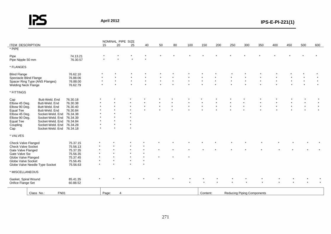
April 2012
IPS-E-PI-221(1)
271
ITEM DESCRIPTION
NOMINAL PIPE SIZE 15 20 25 40 50 80 100 150 200 250 300 350 400 450 500 600
* PIPE Pipe 74.13.21 * * * * * * * * * * * * * * * * Pipe Nipple 50 mm 76.30.57 * * * * * FLANGES Blind Flange 76.62.10 * * * * * * * * * * * * * * * * Spectacle Blind Flange 76.88.06 * * * * * * * * * * * * * * * * Spacer Ring Type (ANS Flanges) 76.88.00 * * * * * * * * * * * * * * * * Welding Neck Flange 76.62.79 * * * * * * * * * * * * * * * * * FITTINGS Cap Butt-Weld. End 76.30.18 * * * * * * * * * * * * * * * * Elbow 45 Deg. Butt-Weld. End 76.30.38 * * * * * * * * * * * * * * * * Elbow 90 Deg. Butt-Weld. End 76.30.40 * * * * * * * * * * * * * * * * Equal Tee Butt-Weld. End 76.30.84 * * * * * * * * * * * * * * * * Elbow 45 Deg. Socket-Weld. End 76.34.38 * * * Elbow 90 Deg. Socket-Weld. End 76.34.39 * * * Equal Tee Socket-Weld. End 76.34.84 * * * Coupling Socket-Weld. End 76.34.28 * * * Cap Socket-Weld. End 76.34.18 * * * * VALVES Check Valve Flanged 75.37.15 * * * * * * * * * * * * * * * * Check Valve Socket 75.56.13 * * * * Gate Valve Flanged 75.37.35 * * * * * * * * * * * * * * * * Gate Valve Sw 75.56.35 * * * * Globe Valve Flanged 75.37.45 * * * * * * * Globe Valve Socket 75.56.45 * * * * Globe Valve Needle Type Socket 75.56.63 * * * * * MISCELLANEOUS Gasket, Spiral Wound 85.41.35 * * * * * * * * * * * * * * * * Orifice Flange Set 60.88.52 * * * * * * * * * *
Class No.: FN01
Page: 4
Content: Reducing Piping Components
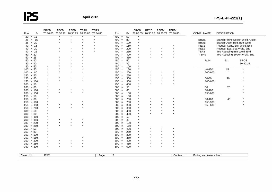
April 2012
IPS-E-PI-221(1)
272
BROB RECB REEB TERB TERS Run Br. 76.80.05 76.30.72 76.30.73 76.30.85 76.34.85
BROB RECB REEB TERB Run Br. 76.80.05 76.30.72 76.30.73 76.30.85
COMP. NAME DESCRIPTION
20 × 15 * * * * 25 × 15 * * * * 25 × 20 * * * * 40 × 15 * * 40 × 20 * * * * 40 × 25 * * * * 50 × 20 * 50 × 25 * * * 50 × 40 * * * 80 × 40 * * * 80 × 50 * * * * 100 × 50 * * * * 100 × 80 * * * * 150 × 50 * 150 × 80 * * * * 150 × 100 * * * * 200 × 50 * 200 × 80 * 200 × 100 * * * * 200 × 150 * * * * 250 × 50 * 250 × 80 * 250 × 100 * * 250 × 150 * * * * 250 × 200 * * * * 300 × 50 * 300 × 80 * 300 × 100 * 300 × 150 * * * * 300 × 200 * * * * 300 × 250 * * * * 350 × 50 * 350 × 80 * 350 × 100 * 350 × 150 * * 350 × 200 * * * * 350 × 250 * * * * 350 × 300 * * * *
400 × 50 * 400 × 80 * 400 × 100 * 400 × 150 * * 400 × 200 * * * * 400 × 250 * * * * 400 × 300 * * * * 400 × 350 * * * * 450 × 50 * 450 × 80 * 450 × 100 * 450 × 150 * 450 × 200 * * * * 450 × 250 * * * * 450 × 300 * * * * 450 × 350 * * * * 450 × 400 * * * * 500 × 50 * 500 × 80 * 500 × 100 * 500 × 150 * 500 × 200 * * * * 500 × 250 * * * * 500 × 300 * * * * 500 × 350 * * * * 500 × 400 * * * * 500 × 450 * * * * 600 × 50 * 600 × 80 * 600 × 100 * 600 × 150 * 600 × 200 * * * * 600 × 250 * * * * 600 × 300 * * * * 600 × 350 * * * * 600 × 400 * * * * 600 × 450 * * * * 600 × 500 * * * *
BROS Branch Fitting Socket-Weld. Outlet BROB Branch Outlet Red. Butt-Weld RECB Reducer Conc. Butt-Weld. End REEB Reducer Ecc. Butt-Weld. End TERB Tee Reducing Butt-Weld. End TERS Tee Reducing Socket-Weld. End RUN Br. BROS 76.80.26 _____________________________________________ 40-150 15 * 200-600 * 50-80 20 * 100-600 * 50 25 * 80-100 * 150-600 * 80-100 40 * 150-300 * 350-600 *
Class No.: FN01 Page: 5 Content: Bolting and Assemblies
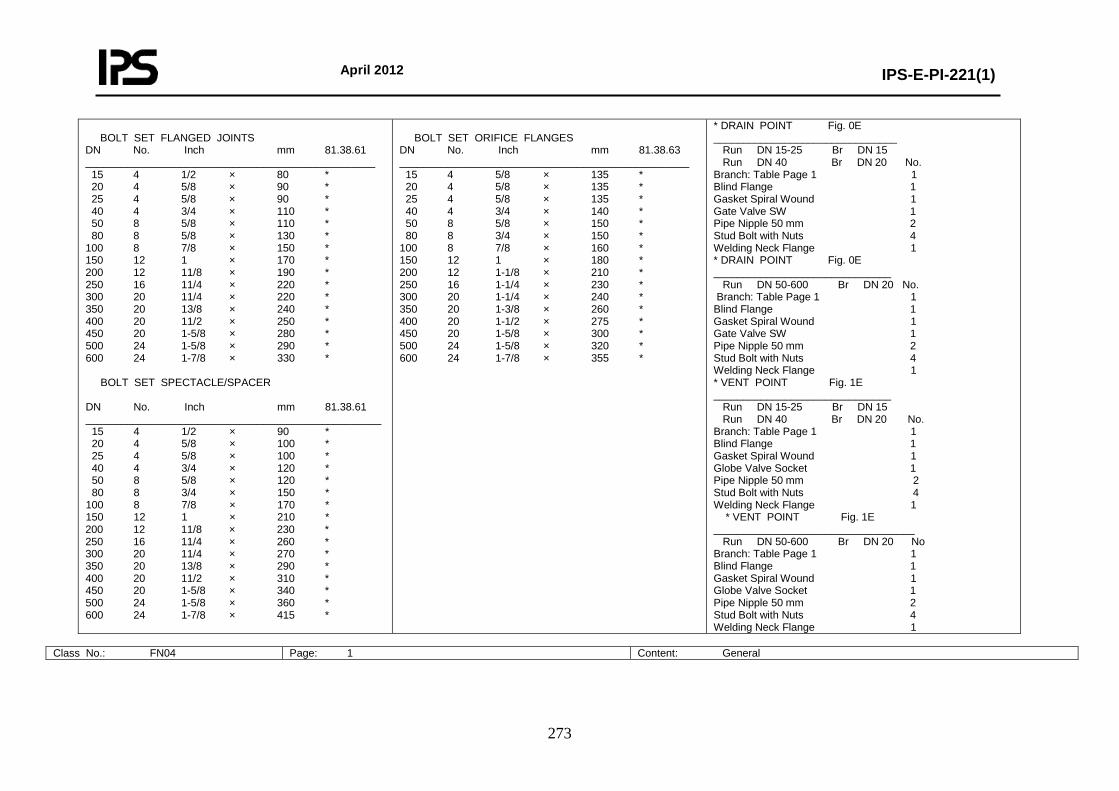
April 2012
IPS-E-PI-221(1)
273
BOLT SET FLANGED JOINTS DN No. Inch mm 81.38.61 _________________________________________________ 15 4 1/2 × 80 * 20 4 5/8 × 90 * 25 4 5/8 × 90 * 40 4 3/4 × 110 * 50 8 5/8 × 110 * 80 8 5/8 × 130 * 100 8 7/8 × 150 * 150 12 1 × 170 * 200 12 11/8 × 190 * 250 16 11/4 × 220 * 300 20 11/4 × 220 * 350 20 13/8 × 240 * 400 20 11/2 × 250 * 450 20 1-5/8 × 280 * 500 24 1-5/8 × 290 * 600 24 1-7/8 × 330 * BOLT SET SPECTACLE/SPACER DN No. Inch mm 81.38.61 __________________________________________________ 15 4 1/2 × 90 * 20 4 5/8 × 100 * 25 4 5/8 × 100 * 40 4 3/4 × 120 * 50 8 5/8 × 120 * 80 8 3/4 × 150 * 100 8 7/8 × 170 * 150 12 1 × 210 * 200 12 11/8 × 230 * 250 16 11/4 × 260 * 300 20 11/4 × 270 * 350 20 13/8 × 290 * 400 20 11/2 × 310 * 450 20 1-5/8 × 340 * 500 24 1-5/8 × 360 * 600 24 1-7/8 × 415 *
BOLT SET ORIFICE FLANGES DN No. Inch mm 81.38.63 _________________________________________________ 15 4 5/8 × 135 * 20 4 5/8 × 135 * 25 4 5/8 × 135 * 40 4 3/4 × 140 * 50 8 5/8 × 150 * 80 8 3/4 × 150 * 100 8 7/8 × 160 * 150 12 1 × 180 * 200 12 1-1/8 × 210 * 250 16 1-1/4 × 230 * 300 20 1-1/4 × 240 * 350 20 1-3/8 × 260 * 400 20 1-1/2 × 275 * 450 20 1-5/8 × 300 * 500 24 1-5/8 × 320 * 600 24 1-7/8 × 355 *
* DRAIN POINT Fig. 0E _______________________________ Run DN 15-25 Br DN 15 Run DN 40 Br DN 20 No. Branch: Table Page 1 1 Blind Flange 1 Gasket Spiral Wound 1 Gate Valve SW 1 Pipe Nipple 50 mm 2 Stud Bolt with Nuts 4 Welding Neck Flange 1 * DRAIN POINT Fig. 0E ______________________________ Run DN 50-600 Br DN 20 No. Branch: Table Page 1 1 Blind Flange 1 Gasket Spiral Wound 1 Gate Valve SW 1 Pipe Nipple 50 mm 2 Stud Bolt with Nuts 4 Welding Neck Flange 1 * VENT POINT Fig. 1E ______________________________ Run DN 15-25 Br DN 15 Run DN 40 Br DN 20 No. Branch: Table Page 1 1 Blind Flange 1 Gasket Spiral Wound 1 Globe Valve Socket 1 Pipe Nipple 50 mm 2 Stud Bolt with Nuts 4 Welding Neck Flange 1 * VENT POINT Fig. 1E __________________________________ Run DN 50-600 Br DN 20 No Branch: Table Page 1 1 Blind Flange 1 Gasket Spiral Wound 1 Globe Valve Socket 1 Pipe Nipple 50 mm 2 Stud Bolt with Nuts 4 Welding Neck Flange 1
Class No.: FN04 Page: 1 Content: General
April 2012
IPS-E-PI-221(1)
274
Base Material: Carbon Steel First Issue: Revision: Rating: PN 100 (Class 600) Date: Corrosion Allowance: 1 mm Sign:
Temperature °C 0 50 100 150 200 250 300 350 400 Pressure Barg. DN 15-600 102.0 100.0 92.7 90.6 87.8 83.6 77.5 73.9 69.1
TABLE OF SCHEDULES
BRANCH CONNECTIONS 90 DEGREES
BRANCH SIZE
DN
Schedule Run
Size 15 20 25 40 50 80 100 150 200 250 300 350 400 450 500 600
15 20 25 40 50 80
100 150 200 250 300 350 400 450 500 600
80 80 80 80 80 80 80 80 80 80 80 80 80 80 80 80
600 C C C C E E E E E E E E E E E A 500 C C C C E E E E E E E E E E A 450 C C C C E E E E E E E E E A 400 C C C C E E E E E E E E A 350 C C C C E E E E E E E A 300 C C C C E E E E E E A 250 C C C C E E E E E A 200 C C C C E E E E A 150 C C C C E E E A 100 C C C C E E A 80 C C C C E A 50 C C C B A 40 C B B A 25 B B A 20 B A 15 A
Notes: - Design limits are acc. flange rating ANSI B16.5 Material Group 1.1. - Piston type check valves for horizontal mounting only. - Application of other types of branch connections shall be subject to prior approval of company.
CODE EXPLANATION OF CHARACTERS A Equal tee B Reducing tee C Branch fitting outlet socket-weld E Branch outlet reducing butt-weld
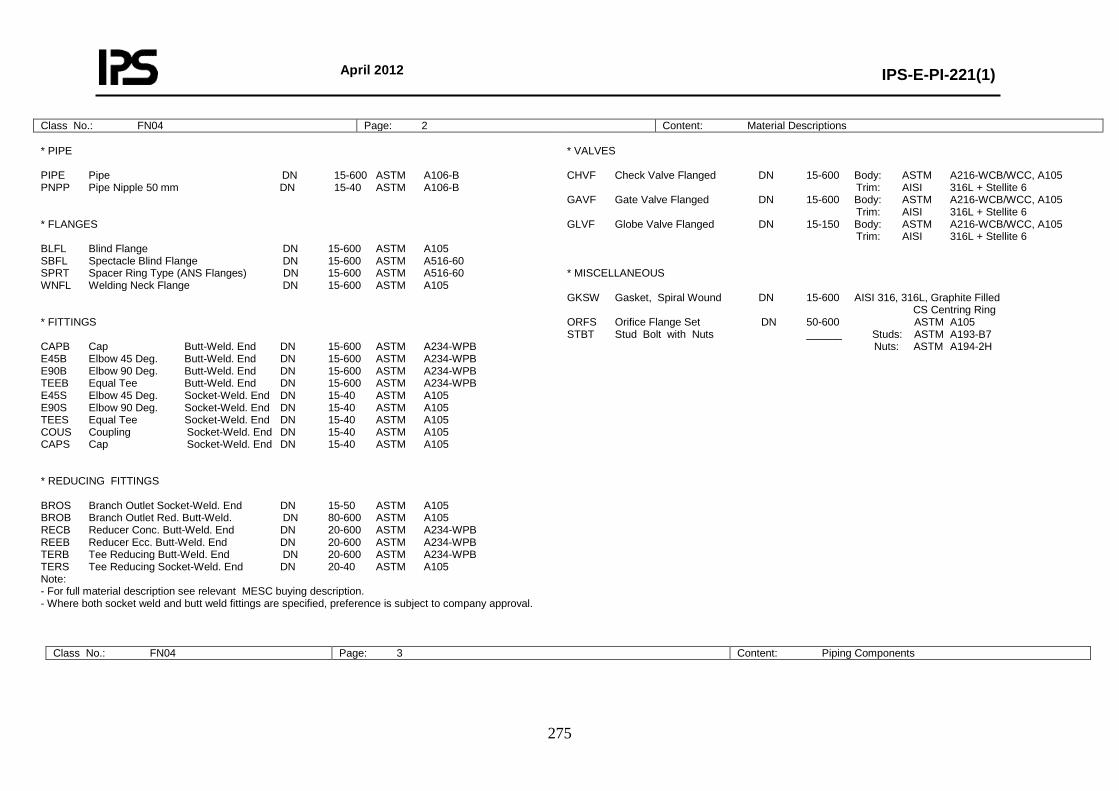
April 2012
IPS-E-PI-221(1)
275
Class No.: FN04 Page: 2 Content: Material Descriptions * PIPE PIPE Pipe DN 15-600 ASTM A106-B PNPP Pipe Nipple 50 mm DN 15-40 ASTM A106-B * FLANGES BLFL Blind Flange DN 15-600 ASTM A105 SBFL Spectacle Blind Flange DN 15-600 ASTM A516-60 SPRT Spacer Ring Type (ANS Flanges) DN 15-600 ASTM A516-60 WNFL Welding Neck Flange DN 15-600 ASTM A105 * FITTINGS CAPB Cap Butt-Weld. End DN 15-600 ASTM A234-WPB E45B Elbow 45 Deg. Butt-Weld. End DN 15-600 ASTM A234-WPB E90B Elbow 90 Deg. Butt-Weld. End DN 15-600 ASTM A234-WPB TEEB Equal Tee Butt-Weld. End DN 15-600 ASTM A234-WPB E45S Elbow 45 Deg. Socket-Weld. End DN 15-40 ASTM A105 E90S Elbow 90 Deg. Socket-Weld. End DN 15-40 ASTM A105 TEES Equal Tee Socket-Weld. End DN 15-40 ASTM A105 COUS Coupling Socket-Weld. End DN 15-40 ASTM A105 CAPS Cap Socket-Weld. End DN 15-40 ASTM A105 * REDUCING FITTINGS BROS Branch Outlet Socket-Weld. End DN 15-50 ASTM A105 BROB Branch Outlet Red. Butt-Weld. DN 80-600 ASTM A105 RECB Reducer Conc. Butt-Weld. End DN 20-600 ASTM A234-WPB REEB Reducer Ecc. Butt-Weld. End DN 20-600 ASTM A234-WPB TERB Tee Reducing Butt-Weld. End DN 20-600 ASTM A234-WPB TERS Tee Reducing Socket-Weld. End DN 20-40 ASTM A105 Note: - For full material description see relevant MESC buying description. - Where both socket weld and butt weld fittings are specified, preference is subject to company approval.
* VALVES CHVF Check Valve Flanged DN 15-600 Body: ASTM A216-WCB/WCC, A105 Trim: AISI 316L + Stellite 6 GAVF Gate Valve Flanged DN 15-600 Body: ASTM A216-WCB/WCC, A105 Trim: AISI 316L + Stellite 6 GLVF Globe Valve Flanged DN 15-150 Body: ASTM A216-WCB/WCC, A105 Trim: AISI 316L + Stellite 6 * MISCELLANEOUS GKSW Gasket, Spiral Wound DN 15-600 AISI 316, 316L, Graphite Filled CS Centring Ring ORFS Orifice Flange Set DN 50-600 ASTM A105 STBT Stud Bolt with Nuts ______ Studs: ASTM A193-B7 Nuts: ASTM A194-2H
Class No.: FN04 Page: 3 Content: Piping Components

April 2012
IPS-E-PI-221(1)
276
NOMINAL PIPE SIZE ITEM DESCRIPTION MESC 15 20 25 40 50 80 100 150 200 250 300 350 400 450 500 600 * PIPE Pipe 74.30.21/31 * * * * * * * * * * * * * * * * Pipe Nipple 50 mm 76.30.57 * * * * * FLANGES Blind Flange 76.62.10 * * * * * * * * * * * * * * * * Spectacle Blind Flange 76.88.06 * * * * * * * * * * * * * * * * Spacer Ring Type (ANS Flanges) 76.88.16 * * * * * * * * * * * * * * * * Welding Neck Flange 76.62.79 * * * * * * * * * * * * * * * * * FITTINGS Cap Butt-Weld. End 76.30.18 * * * * * * * * * * * * * * * * Elbow 45 Deg. Butt-Weld. End 76.30.38 * * * * * * * * * * * * * * * * Elbow 90 Deg. Butt-Weld. End 76.30.39/40 * * * * * * * * * * * * * * * * Equal Tee Butt-Weld. End 76.30.84 * * * * * * * * * * * * * * * * Elbow 45 Deg. Socket-Weld. End 76.34.38 * * * * Elbow 90 Deg. Socket-Weld. End 76.34.39 * * * * Equal Tee Socket-Weld. End 76.34.84 * * * * Coupling Socket-Weld. End 76.34.28 * * * * Cap Socket-Weld. End 76.34.18 * * * * * VALVES Check Valve Flanged 75.37.15 * * * * * * * * * * * * * * * * Gate Valve Flanged 75.37.35 * * * * * * * * * * * * * * * * Globe Valve Flanged 75.37.45 * * * * * * * * * MISCELLANEOUS Gasket, Spiral Wound 85.41.36 * * * * * * * * * * * * * * * * Orifice Flange Set 60.88.52 * * * * * * * * * * * *
Class No.: FN04 Page: 4 Content: Reducing Piping Components
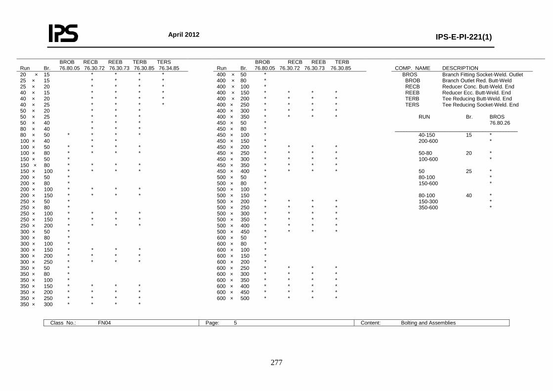
April 2012
IPS-E-PI-221(1)
277
BROB RECB REEB TERB TERS Run Br. 76.80.05 76.30.72 76.30.73 76.30.85 76.34.85
BROB RECB REEB TERB Run Br. 76.80.05 76.30.72 76.30.73 76.30.85
COMP. NAME DESCRIPTION
20 × 15 * * * * 25 × 15 * * * * 25 × 20 * * * * 40 × 15 * * * * 40 × 20 * * * * 40 × 25 * * * * 50 × 20 * * * 50 × 25 * * * 50 × 40 * * * 80 × 40 * * * 80 × 50 * * * * 100 × 40 * * 100 × 50 * * * * 100 × 80 * * * * 150 × 50 * 150 × 80 * * * * 150 × 100 * * * * 200 × 50 * 200 × 80 * 200 × 100 * * * * 200 × 150 * * * * 250 × 50 * 250 × 80 * 250 × 100 * * * * 250 × 150 * * * * 250 × 200 * * * * 300 × 50 * 300 × 80 * 300 × 100 * 300 × 150 * * * * 300 × 200 * * * * 300 × 250 * * * * 350 × 50 * 350 × 80 * 350 × 100 * 350 × 150 * * * * 350 × 200 * * * * 350 × 250 * * * * 350 × 300 * * * *
400 × 50 * 400 × 80 * 400 × 100 * 400 × 150 * * * * 400 × 200 * * * * 400 × 250 * * * * 400 × 300 * * * * 400 × 350 * * * * 450 × 50 * 450 × 80 * 450 × 100 * 450 × 150 * 450 × 200 * * * * 450 × 250 * * * * 450 × 300 * * * * 450 × 350 * * * * 450 × 400 * * * * 500 × 50 * 500 × 80 * 500 × 100 * 500 × 150 * 500 × 200 * * * * 500 × 250 * * * * 500 × 300 * * * * 500 × 350 * * * * 500 × 400 * * * * 500 × 450 * * * * 600 × 50 * 600 × 80 * 600 × 100 * 600 × 150 * 600 × 200 * 600 × 250 * * * * 600 × 300 * * * * 600 × 350 * * * * 600 × 400 * * * * 600 × 450 * * * * 600 × 500 * * * *
BROS Branch Fitting Socket-Weld. Outlet BROB Branch Outlet Red. Butt-Weld RECB Reducer Conc. Butt-Weld. End REEB Reducer Ecc. Butt-Weld. End TERB Tee Reducing Butt-Weld. End TERS Tee Reducing Socket-Weld. End RUN Br. BROS 76.80.26 __________________________________________ 40-150 15 * 200-600 * 50-80 20 * 100-600 * 50 25 * 80-100 * 150-600 * 80-100 40 * 150-300 * 350-600 *
Class No.: FN04 Page: 5 Content: Bolting and Assemblies
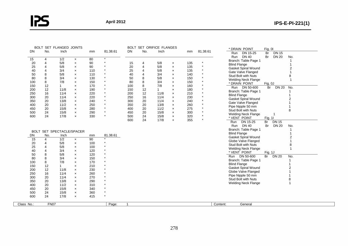
April 2012
IPS-E-PI-221(1)
278
Class No.: FN07 Page: 1 Content: General
* DRAIN POINT Fig. 0I Run DN 15-25 Br DN 15 Run DN 40 Br DN 20 No. Branch: Table Page 1 1 Blind Flange 1 Gasket Spiral Wound 2 Gate Valve Flanged 1 Stud Bolt with Nuts 8 Welding Neck Flange 1 * DRAIN POINT Fig. 0J Run DN 50-600 Br DN 20 No. Branch: Table Page 1 1 Blind Flange 1 Gasket Spiral Wound 2 Gate Valve Flanged 1 Pipe Nipple 50 mm 1 Stud Bolt with Nuts 8 Welding Neck Flange 1 * VENT POINT Fig. 1I Run DN 15-25 Br DN 15 Run DN 40 Br DN 20 No. Branch: Table Page 1 1 Blind Flange 1 Gasket Spiral Wound 2 Globe Valve Flanged 1 Stud Bolt with Nuts 8 Welding Neck Flange 1 * VENT POINT Fig. 1J Run DN 50-600 Br DN 20 No. Branch: Table Page 1 1 Blind Flange 1 Gasket Spiral Wound 2 Globe Valve Flanged 1 Pipe Nipple 50 mm 1 Stud Bolt with Nuts 8 Welding Neck Flange 1
BOLT SET FLANGED JOINTS DN No. Inch mm 81.38.61
BOLT SET ORIFICE FLANGES DN No. Inch mm 81.38.61
15 4 1/2 × 80 * 20 4 5/8 × 90 * 25 4 5/8 × 90 * 40 4 3/4 × 110 * 50 8 5/8 × 110 * 80 8 3/4 × 130 * 100 8 7/8 × 150 * 150 12 1 × 170 * 200 12 11/8 × 190 * 250 16 11/4 × 220 * 300 20 11/4 × 220 * 350 20 13/8 × 240 * 400 20 11/2 × 250 * 450 20 15/8 × 280 * 500 24 15/8 × 290 * 600 24 17/8 × 330 *
15 4 5/8 × 135 * 20 4 5/8 × 135 * 25 4 5/8 × 135 * 40 4 3/4 × 140 * 50 8 5/8 × 150 * 80 8 3/4 × 150 * 100 8 7/8 × 160 * 150 12 1 × 180 * 200 12 11/8 × 210 * 250 16 11/4 × 230 * 300 20 11/4 × 240 * 350 20 13/8 × 260 * 400 20 11/2 × 275 * 450 20 15/8 × 300 * 500 24 15/8 × 320 * 600 24 17/8 × 355 *
BOLT SET SPECTACLE/SPACER DN No. Inch mm 81.38.61 15 4 1/2 × 90 * 20 4 5/8 × 100 * 25 4 5/8 × 100 * 40 4 3/4 × 120 * 50 8 5/8 × 120 * 80 8 3/4 × 150 * 100 8 7/8 × 170 * 150 12 1 × 210 * 200 12 11/8 × 230 * 250 16 11/4 × 260 * 300 20 11/4 × 270 * 350 20 13/8 × 290 * 400 20 11/2 × 310 * 450 20 15/8 × 340 * 500 24 15/8 × 360 * 600 24 17/8 × 415 *
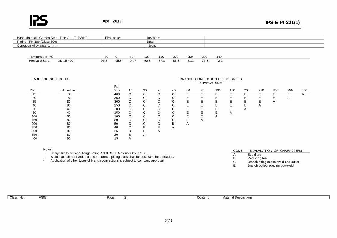
April 2012
IPS-E-PI-221(1)
279
Base Material: Carbon Steel, Fine Gr. LT, PWHT First Issue: Revision: Rating: PN 100 (Class 600) Date: Corrosion Allowance: 1 mm Sign:
Temperature °C -50 0 50 100 150 200 250 300 340 Pressure Barg. DN 15-400 95.8 95.8 94.7 90.3 87.8 85.3 81.1 75.3 72.2
TABLE OF SCHEDULES
BRANCH CONNECTIONS 90 DEGREES
BRANCH SIZE DN
Schedule
Run Size 15 20 25 40 50 80 100 150 200 250 300 350 400
15 20 25 40 50 80 100 150 200 250 300 350 400
80 80 80 80 40 40 80 80 80 80 80 80 80
400 C C C C E E E E E E E E A 350 C C C C E E E E E E E A 300 C C C C E E E E E E A 250 C C C C E E E E E A 200 C C C C E E E E A 150 C C C C E E E A 100 C C C C E E A 80 C C C C E A 50 C C C B A 40 C B B A 25 B B A 20 B A 15 A
Notes: - Design limits are acc. flange rating ANSI B16.5 Material Group 1.3. - Welds, attachment welds and cord formed piping parts shall be post-weld heat treaded. - Application of other types of branch connections is subject to company approval.
Class No.: FN07 Page: 2 Content: Material Descriptions
CODE EXPLANATION OF CHARACTERS A Equal tee B Reducing tee C Branch fitting socket weld end outlet E Branch outlet reducing butt-weld
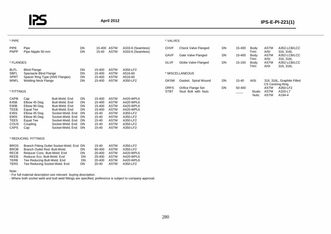
April 2012
IPS-E-PI-221(1)
280
* PIPE PIPE Pipe DN 15-400 ASTM A333-6 (Seamless) PNPP Pipe Nipple 50 mm DN 15-40 ASTM A333-6 (Seamless) * FLANGES BLFL Blind Flange DN 15-400 ASTM A350-LF2 SBFL Spectacle Blind Flange DN 15-400 ASTM A516-60 SPRT Spacer Ring Type (ANS Flanges) DN 15-400 ASTM A516-60 WNFL Welding Neck Flange DN 15-400 ASTM A350-LF2 * FITTINGS CAPB Cap Butt-Weld. End DN 15-400 ASTM A420-WPL6 E45B Elbow 45 Deg. Butt-Weld. End DN 15-400 ASTM A420-WPL6 E90B Elbow 90 Deg. Butt-Weld. End DN 15-400 ASTM A420-WPL6 TEEB Equal Tee Butt-Weld. End DN 15-400 ASTM A420-WPL6 E45S Elbow 45 Deg. Socket-Weld. End DN 15-40 ASTM A350-LF2 E90S Elbow 90 Deg. Socket-Weld. End DN 15-40 ASTM A350-LF2 TEES Equal Tee Socket-Weld. End DN 15-40 ASTM A350-LF2 COUS Coupling Socket-Weld. End DN 15-40 ASTM A350-LF2 CAPS Cap Socket-Weld. End DN 15-40 ASTM A350-LF2 * REDUCING FITTINGS BROS Branch Fitting Outlet Socket-Weld. End DN 15-40 ASTM A350-LF2 BROB Branch Outlet Red. Butt-Weld. DN 80-400 ASTM A350-LF2 RECB Reducer Conc. Butt-Weld. End DN 20-400 ASTM A420-WPL6 REEB Reducer Ecc. Butt-Weld. End DN 20-400 ASTM A420-WPL6 TERB Tee Reducing Butt-Weld. End DN 20-400 ASTM A420-WPL6 TERS Tee Reducing Socket-Weld. End DN 20-40 ASTM A350-LF2 Note: - For full material description see relevant buying description. - Where both socket weld and butt weld fittings are specified, preference is subject to company approval.
* VALVES CHVF Check Valve Flanged DN 15-400 Body: ASTM A352-LCB/LCC Trim: AISI 316, 316L GAVF Gate Valve Flanged DN 15-400 Body: ASTM A352-LCB/LCC Trim: AISI 316, 316L GLVF Globe Valve Flanged DN 15-150 Body: ASTM A352-LCB/LCC Trim: AISI 316, 316L * MISCELLANEOUS GKSW Gasket, Spiral Wound DN 15-40 AISI 316, 316L, Graphite Filled CS Centring Ring ORFS Orifice Flange Set DN 50-400 ASTM A350-LF2 STBT Stud Bolt with Nuts ____ Studs: ASTM A320-L7 Nuts: ASTM A194-4
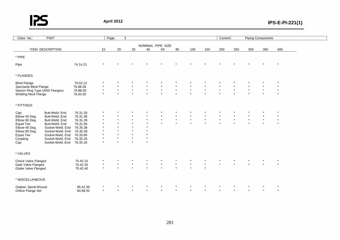
April 2012
IPS-E-PI-221(1)
281
Class No.: FN07 Page: 3 Content: Piping Components
NOMINAL PIPE SIZE ITEM DESCRIPTION 15 20 25 40 50 80 100 150 200 250 300 350 400
* PIPE Pipe 74.14.21 * * * * * * * * * * * * * * FLANGES Blind Flange 76.62.12 * * * * * * * * * * * * * Spectacle Blind Flange 76.88.06 * * * * * * * * * * * * * Spacer Ring Type (ANS Flanges) 76.88.00 * * * * * * * * * * * * * Welding Neck Flange 76.62.82 * * * * * * * * * * * * * * FITTINGS Cap Butt-Weld. End 76.31.18 * * * * * * * * * * * * * Elbow 45 Deg. Butt-Weld. End 76.31.38 * * * * * * * * * * * * * Elbow 90 Deg. Butt-Weld. End 76.31.39 * * * * * * * * * * * * * Equal Tee Butt-Weld. End 76.31.84 * * * * * * * * * * * * * Elbow 45 Deg. Socket-Weld. End 76.35.38 * * * * Elbow 90 Deg. Socket-Weld. End 76.35.39 * * * * Equal Tee Socket-Weld. End 76.35.80 * * * * Coupling Socket-Weld. End 76.35.28 * * * * Cap Socket-Weld. End 76.35.18 * * * * * VALVES Check Valve Flanged 75.42.15 * * * * * * * * * * * * * Gate Valve Flanged 75.42.35 * * * * * * * * * * * * * Globe Valve Flanged 75.42.40 * * * * * * * * * MISCELLANEOUS Gasket, Spiral Wound 85.41.36 * * * * * * * * * * * * * Orifice Flange Set 60.88.52 * * * * * * * * * * * * *
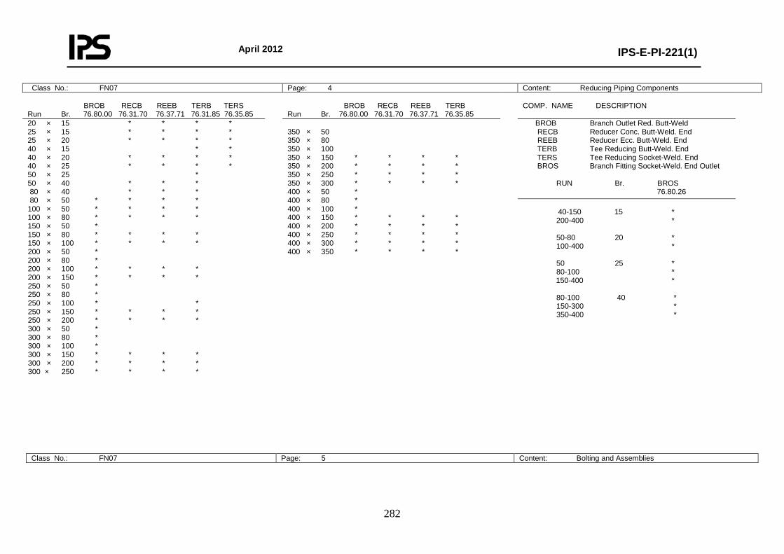
April 2012
IPS-E-PI-221(1)
282
Class No.: FN07 Page: 4 Content: Reducing Piping Components BROB RECB REEB TERB TERS Run Br. 76.80.00 76.31.70 76.37.71 76.31.85 76.35.85
BROB RECB REEB TERB Run Br. 76.80.00 76.31.70 76.37.71 76.35.85
COMP. NAME DESCRIPTION
20 × 15 * * * * 25 × 15 * * * * 25 × 20 * * * * 40 × 15 * * 40 × 20 * * * * 40 × 25 * * * * 50 × 25 * 50 × 40 * * * 80 × 40 * * * 80 × 50 * * * * 100 × 50 * * * * 100 × 80 * * * * 150 × 50 * 150 × 80 * * * * 150 × 100 * * * * 200 × 50 * 200 × 80 * 200 × 100 * * * * 200 × 150 * * * * 250 × 50 * 250 × 80 * 250 × 100 * * 250 × 150 * * * * 250 × 200 * * * * 300 × 50 * 300 × 80 * 300 × 100 * 300 × 150 * * * * 300 × 200 * * * * 300 × 250 * * * *
350 × 50 350 × 80 350 × 100 350 × 150 * * * * 350 × 200 * * * * 350 × 250 * * * * 350 × 300 * * * * 400 × 50 * 400 × 80 * 400 × 100 * 400 × 150 * * * * 400 × 200 * * * * 400 × 250 * * * * 400 × 300 * * * * 400 × 350 * * * *
BROB Branch Outlet Red. Butt-Weld RECB Reducer Conc. Butt-Weld. End REEB Reducer Ecc. Butt-Weld. End TERB Tee Reducing Butt-Weld. End TERS Tee Reducing Socket-Weld. End BROS Branch Fitting Socket-Weld. End Outlet RUN Br. BROS 76.80.26
40-150 15 * 200-400 * 50-80 20 * 100-400 * 50 25 * 80-100 * 150-400 * 80-100 40 * 150-300 * 350-400 *
Class No.: FN07 Page: 5 Content: Bolting and Assemblies
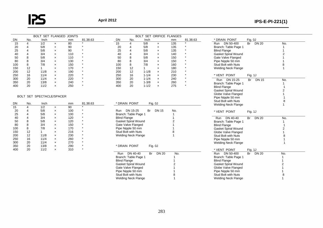
April 2012
IPS-E-PI-221(1)
283
BOLT SET FLANGED JOINTS DN No. Inch mm 81.38.63
BOLT SET ORIFICE FLANGES DN No. Inch mm 81.38.63
* DRAIN POINT Fig. 0J
15 4 1/2 × 80 * 20 4 5/8 × 90 * 25 4 5/8 × 90 * 40 4 3/4 × 110 * 50 8 5/8 × 110 * 80 8 3/4 × 130 * 100 8 7/8 × 150 * 150 12 1 × 170 * 200 12 11/8 × 190 * 250 16 11/4 × 220 * 300 20 11/4 × 220 * 350 20 13/8 × 240 * 400 20 11/2 × 250 * BOLT SET SPECTACLE/SPACER DN No. Inch mm 81.38.63
15 4 5/8 × 135 * 20 4 5/8 × 135 * 25 4 5/8 × 135 * 40 4 3/4 × 140 * 50 8 5/8 × 150 * 80 8 3/4 × 150 * 100 8 7/8 × 160 * 150 12 1 × 180 * 200 12 1-1/8 × 210 * 250 16 1-1/4 × 230 * 300 20 1-1/4 × 240 * 350 20 1-3/8 × 260 * 400 20 1-1/2 × 275 * * DRAIN POINT Fig. 0J
Run DN 50-400 Br DN 20 No. Branch: Table Page 1 1 Blind Flange 1 Gasket Spiral Wound 2 Gate Valve Flanged 1 Pipe Nipple 50 mm 1 Stud Bolt with Nuts 8 Welding Neck Flange 1 * VENT POINT Fig. 1J Run DN 15-25 Br DN 15 No. Branch: Table Page 1 1 Blind Flange 1 Gasket Spiral Wound 2 Globe Valve Flanged 1 Pipe Nipple 50 mm 1 Stud Bolt with Nuts 8 Welding Neck Flange 1 * VENT POINT Fig. 1J
15 4 1/2 × 90 * 20 4 5/8 × 100 * 25 4 5/8 × 100 * 40 4 3/4 × 120 * 50 8 5/8 × 120 * 80 8 3/4 × 150 * 100 8 7/8 × 170 * 150 12 1 × 216 * 200 12 11/8 × 230 * 250 16 11/4 × 260 * 300 20 11/4 × 270 * 350 20 13/8 × 290 * 400 20 11/2 × 310 *
Run DN 15-25 Br DN 15 No. Branch: Table Page 1 1 Blind Flange 1 Gasket Spiral Wound 2 Gate Valve Flanged 1 Pipe Nipple 50 mm 1 Stud Bolt with Nuts 8 Welding Neck Flange 1 * DRAIN POINT Fig. 0J
Run DN 40-40 Br DN 20 No. Branch: Table Page 1 1 Blind Flange 1 Gasket Spiral Wound 2 Globe Valve Flanged 1 Stud Bolt with Nuts 8 Pipe Nipple 50 mm 1 Welding Neck Flange 1 * VENT POINT Fig. 1J
Run DN 40-40 Br DN 20 No. Branch: Table Page 1 1 Blind Flange 1 Gasket Spiral Wound 2 Gate Valve Flanged 1 Pipe Nipple 50 mm 1 Stud Bolt with Nuts 8 Welding Neck Flange 1
Run DN 50-400 Br DN 20 No. Branch: Table Page 1 1 Blind Flange 1 Gasket Spiral Wound 2 Globe Valve Flanged 1 Pipe Nipple 50 mm 1 Stud Bolt with Nuts 8 Welding Neck Flange 1
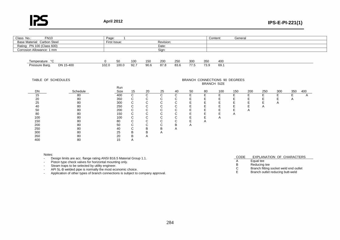
April 2012
IPS-E-PI-221(1)
284
Class No.: FN10 Page: 1 Content: General Base Material: Carbon Steel First Issue: Revision: Rating: PN 100 (Class 600) Date: Corrosion Allowance: 1 mm Sign:
Temperature °C 0 50 100 150 200 250 300 350 400 Pressure Barg. DN 15-400 102.0 100.0 92.7 90.6 87.8 83.6 77.5 73.9 69.1
TABLE OF SCHEDULES
BRANCH CONNECTIONS 90 DEGREES
BRANCH SIZE
DN
Schedule Run
Size 15 20 25 40 50 80 100 150 200 250 300 350 400 15 20 25 40 50 80 100 150 200 250 300 350 400
80 80 80 80 80 80 80 80 80 80 80 80 80
400 C C C C E E E E E E E E A 350 C C C C E E E E E E E A 300 C C C C E E E E E E A 250 C C C C E E E E E A 200 C C C C E E E E A 150 C C C C E E E A 100 C C C C E E A 80 C C C C E A 50 C C C B A 40 C B B A 25 B B A 20 B A 15 A
Notes: - Design limits are acc. flange rating ANSI B16.5 Material Group 1.1. - Piston type check valves for horizontal mounting only. - Steam traps to be selected by utility engineer. - API 5L-B welded pipe is normally the most economic choice. - Application of other types of branch connections is subject to company approval.
CODE EXPLANATION OF CHARACTERS A Equal tee B Reducing tee C Branch fitting socket weld end outlet E Branch outlet reducing butt-weld
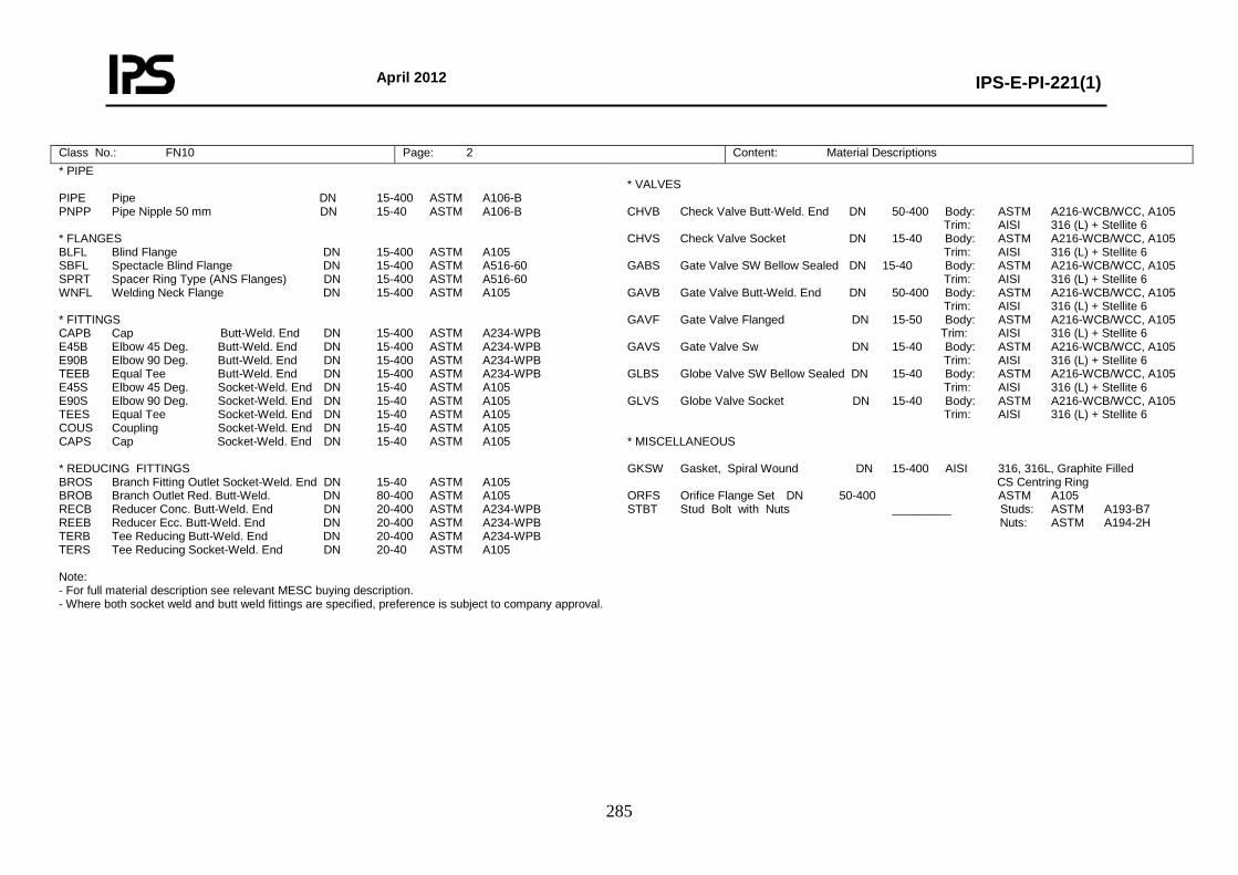
April 2012
IPS-E-PI-221(1)
285
Class No.: FN10 Page: 2 Content: Material Descriptions * PIPE PIPE Pipe DN 15-400 ASTM A106-B PNPP Pipe Nipple 50 mm DN 15-40 ASTM A106-B * FLANGES BLFL Blind Flange DN 15-400 ASTM A105 SBFL Spectacle Blind Flange DN 15-400 ASTM A516-60 SPRT Spacer Ring Type (ANS Flanges) DN 15-400 ASTM A516-60 WNFL Welding Neck Flange DN 15-400 ASTM A105 * FITTINGS CAPB Cap Butt-Weld. End DN 15-400 ASTM A234-WPB E45B Elbow 45 Deg. Butt-Weld. End DN 15-400 ASTM A234-WPB E90B Elbow 90 Deg. Butt-Weld. End DN 15-400 ASTM A234-WPB TEEB Equal Tee Butt-Weld. End DN 15-400 ASTM A234-WPB E45S Elbow 45 Deg. Socket-Weld. End DN 15-40 ASTM A105 E90S Elbow 90 Deg. Socket-Weld. End DN 15-40 ASTM A105 TEES Equal Tee Socket-Weld. End DN 15-40 ASTM A105 COUS Coupling Socket-Weld. End DN 15-40 ASTM A105 CAPS Cap Socket-Weld. End DN 15-40 ASTM A105 * REDUCING FITTINGS BROS Branch Fitting Outlet Socket-Weld. End DN 15-40 ASTM A105 BROB Branch Outlet Red. Butt-Weld. DN 80-400 ASTM A105 RECB Reducer Conc. Butt-Weld. End DN 20-400 ASTM A234-WPB REEB Reducer Ecc. Butt-Weld. End DN 20-400 ASTM A234-WPB TERB Tee Reducing Butt-Weld. End DN 20-400 ASTM A234-WPB TERS Tee Reducing Socket-Weld. End DN 20-40 ASTM A105 Note: - For full material description see relevant MESC buying description. - Where both socket weld and butt weld fittings are specified, preference is subject to company approval.
* VALVES CHVB Check Valve Butt-Weld. End DN 50-400 Body: ASTM A216-WCB/WCC, A105 Trim: AISI 316 (L) + Stellite 6 CHVS Check Valve Socket DN 15-40 Body: ASTM A216-WCB/WCC, A105 Trim: AISI 316 (L) + Stellite 6 GABS Gate Valve SW Bellow Sealed DN 15-40 Body: ASTM A216-WCB/WCC, A105 Trim: AISI 316 (L) + Stellite 6 GAVB Gate Valve Butt-Weld. End DN 50-400 Body: ASTM A216-WCB/WCC, A105 Trim: AISI 316 (L) + Stellite 6 GAVF Gate Valve Flanged DN 15-50 Body: ASTM A216-WCB/WCC, A105 Trim: AISI 316 (L) + Stellite 6 GAVS Gate Valve Sw DN 15-40 Body: ASTM A216-WCB/WCC, A105 Trim: AISI 316 (L) + Stellite 6 GLBS Globe Valve SW Bellow Sealed DN 15-40 Body: ASTM A216-WCB/WCC, A105 Trim: AISI 316 (L) + Stellite 6 GLVS Globe Valve Socket DN 15-40 Body: ASTM A216-WCB/WCC, A105 Trim: AISI 316 (L) + Stellite 6 * MISCELLANEOUS GKSW Gasket, Spiral Wound DN 15-400 AISI 316, 316L, Graphite Filled CS Centring Ring ORFS Orifice Flange Set DN 50-400 ASTM A105 STBT Stud Bolt with Nuts _________ Studs: ASTM A193-B7 Nuts: ASTM A194-2H
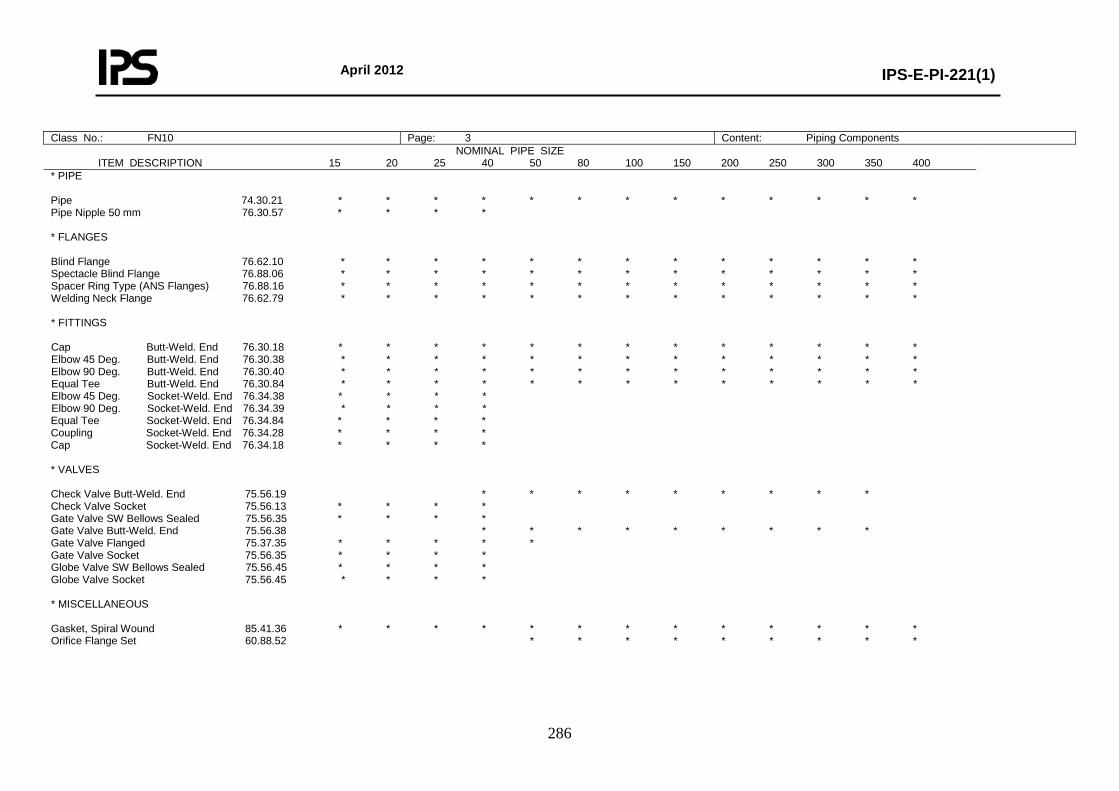
April 2012
IPS-E-PI-221(1)
286
Class No.: FN10 Page: 3 Content: Piping Components
NOMINAL PIPE SIZE ITEM DESCRIPTION 15 20 25 40 50 80 100 150 200 250 300 350 400
* PIPE Pipe 74.30.21 * * * * * * * * * * * * * Pipe Nipple 50 mm 76.30.57 * * * * * FLANGES Blind Flange 76.62.10 * * * * * * * * * * * * * Spectacle Blind Flange 76.88.06 * * * * * * * * * * * * * Spacer Ring Type (ANS Flanges) 76.88.16 * * * * * * * * * * * * * Welding Neck Flange 76.62.79 * * * * * * * * * * * * * * FITTINGS Cap Butt-Weld. End 76.30.18 * * * * * * * * * * * * * Elbow 45 Deg. Butt-Weld. End 76.30.38 * * * * * * * * * * * * * Elbow 90 Deg. Butt-Weld. End 76.30.40 * * * * * * * * * * * * * Equal Tee Butt-Weld. End 76.30.84 * * * * * * * * * * * * * Elbow 45 Deg. Socket-Weld. End 76.34.38 * * * * Elbow 90 Deg. Socket-Weld. End 76.34.39 * * * * Equal Tee Socket-Weld. End 76.34.84 * * * * Coupling Socket-Weld. End 76.34.28 * * * * Cap Socket-Weld. End 76.34.18 * * * * * VALVES Check Valve Butt-Weld. End 75.56.19 * * * * * * * * * Check Valve Socket 75.56.13 * * * * Gate Valve SW Bellows Sealed 75.56.35 * * * * Gate Valve Butt-Weld. End 75.56.38 * * * * * * * * * Gate Valve Flanged 75.37.35 * * * * * Gate Valve Socket 75.56.35 * * * * Globe Valve SW Bellows Sealed 75.56.45 * * * * Globe Valve Socket 75.56.45 * * * * * MISCELLANEOUS Gasket, Spiral Wound 85.41.36 * * * * * * * * * * * * * Orifice Flange Set 60.88.52 * * * * * * * * *

April 2012
IPS-E-PI-221(1)
287
Class No.: FN10 Page: 4 Content: Reducing Piping Components BROB RECB REEB TERB TERS Run Br. 76.80.05 76.30.71 76.30.73 76.30.85 76.34.85
BROB RECB REEB TERB Run Br. 76.80.05 76.30.71 76.30.73 76.30.85
COMP. NAME DESCRIPTION
20 × 15 * * * * 25 × 15 * * * * 25 × 20 * * * * 40 × 15 * * * * 40 × 20 * * * * 40 × 25 * * * * 50 × 20 * * 50 × 25 * * 50 × 40 * * 80 × 40 * * * 80 × 50 * * * * 100 × 40 * * 100 × 50 * * * * 100 × 80 * * * * 150 × 50 * 150 × 80 * * * * 150 × 100 * * * * 200 × 50 * 200 × 80 * 200 × 100 * * * * 200 × 150 * * * * 250 × 50 * 250 × 80 * 250 × 100 * * * * 250 × 150 * * * * 250 × 200 * * * * 300 × 50 * 300 × 80 * 300 × 100 * 300 × 150 * * * * 300 × 200 * * * * 300 × 250 * * * * 350 × 50 * 350 × 80 * 350 × 100 * 350 × 150 * * * * 350 × 200 * * * * 350 × 250 * * * * 350 × 300 * * * *
400 × 50 * 400 × 80 * 400 × 100 * 400 × 150 * * * * 400 × 200 * * * * 400 × 250 * * * * 400 × 300 * * * * 400 × 350 * * * *
BROS Branch Fitting Socket-Weld. Outlet BROB Branch Outlet Red. Butt-Weld RECB Reducer Conc. Butt-Weld. End REEB Reducer Ecc. Butt-Weld. End TERB Tee Reducing Butt-Weld. End TERS Tee Reducing Socket-Weld. End RUN Br. BROS 76.80.26
40-150 15 * 200-400 * 50-80 20 * 100-400 * 50 25 * 80-100 * 150-400 * 80-100 40 * 150-300 * 350-400 *
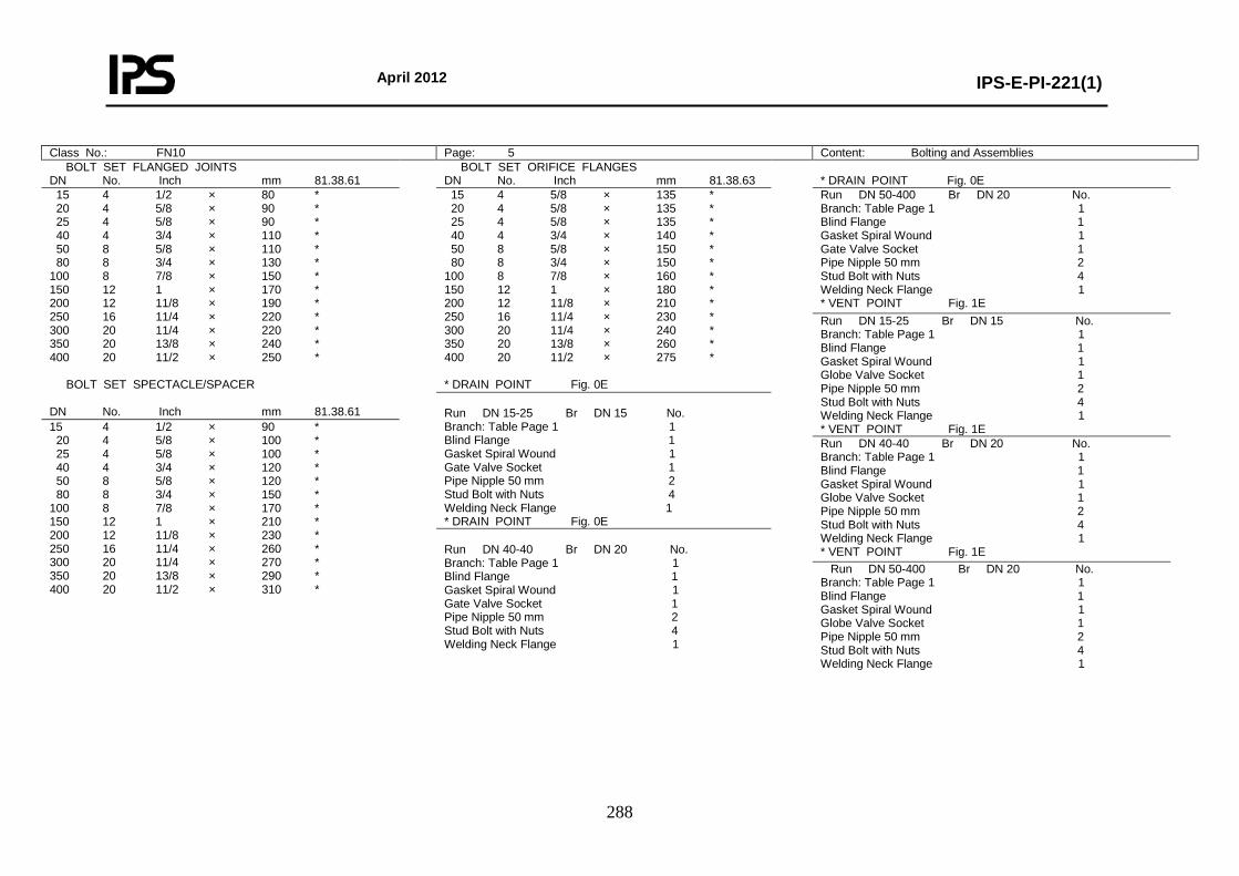
April 2012
IPS-E-PI-221(1)
288
Class No.: FN10 Page: 5 Content: Bolting and Assemblies BOLT SET FLANGED JOINTS DN No. Inch mm 81.38.61
BOLT SET ORIFICE FLANGES DN No. Inch mm 81.38.63
* DRAIN POINT Fig. 0E
15 4 1/2 × 80 * 20 4 5/8 × 90 * 25 4 5/8 × 90 * 40 4 3/4 × 110 * 50 8 5/8 × 110 * 80 8 3/4 × 130 * 100 8 7/8 × 150 * 150 12 1 × 170 * 200 12 11/8 × 190 * 250 16 11/4 × 220 * 300 20 11/4 × 220 * 350 20 13/8 × 240 * 400 20 11/2 × 250 * BOLT SET SPECTACLE/SPACER DN No. Inch mm 81.38.61
15 4 5/8 × 135 * 20 4 5/8 × 135 * 25 4 5/8 × 135 * 40 4 3/4 × 140 * 50 8 5/8 × 150 * 80 8 3/4 × 150 * 100 8 7/8 × 160 * 150 12 1 × 180 * 200 12 11/8 × 210 * 250 16 11/4 × 230 * 300 20 11/4 × 240 * 350 20 13/8 × 260 * 400 20 11/2 × 275 * * DRAIN POINT Fig. 0E
Run DN 50-400 Br DN 20 No. Branch: Table Page 1 1 Blind Flange 1 Gasket Spiral Wound 1 Gate Valve Socket 1 Pipe Nipple 50 mm 2 Stud Bolt with Nuts 4 Welding Neck Flange 1 * VENT POINT Fig. 1E Run DN 15-25 Br DN 15 No. Branch: Table Page 1 1 Blind Flange 1 Gasket Spiral Wound 1 Globe Valve Socket 1 Pipe Nipple 50 mm 2 Stud Bolt with Nuts 4 Welding Neck Flange 1 * VENT POINT Fig. 1E
Run DN 15-25 Br DN 15 No. Branch: Table Page 1 1 Blind Flange 1 Gasket Spiral Wound 1 Gate Valve Socket 1 Pipe Nipple 50 mm 2 Stud Bolt with Nuts 4 Welding Neck Flange 1 * DRAIN POINT Fig. 0E
15 4 1/2 × 90 * 20 4 5/8 × 100 * 25 4 5/8 × 100 * 40 4 3/4 × 120 * 50 8 5/8 × 120 * 80 8 3/4 × 150 * 100 8 7/8 × 170 * 150 12 1 × 210 * 200 12 11/8 × 230 * 250 16 11/4 × 260 * 300 20 11/4 × 270 * 350 20 13/8 × 290 * 400 20 11/2 × 310 *
Run DN 40-40 Br DN 20 No. Branch: Table Page 1 1 Blind Flange 1 Gasket Spiral Wound 1 Globe Valve Socket 1 Pipe Nipple 50 mm 2 Stud Bolt with Nuts 4 Welding Neck Flange 1 * VENT POINT Fig. 1E
Run DN 40-40 Br DN 20 No. Branch: Table Page 1 1 Blind Flange 1 Gasket Spiral Wound 1 Gate Valve Socket 1 Pipe Nipple 50 mm 2 Stud Bolt with Nuts 4 Welding Neck Flange 1
Run DN 50-400 Br DN 20 No. Branch: Table Page 1 1 Blind Flange 1 Gasket Spiral Wound 1 Globe Valve Socket 1 Pipe Nipple 50 mm 2 Stud Bolt with Nuts 4 Welding Neck Flange 1
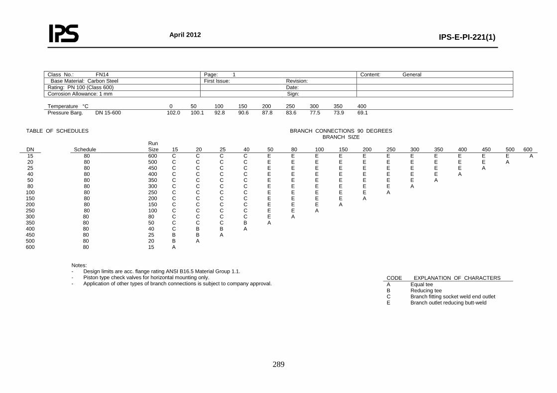
April 2012
IPS-E-PI-221(1)
289
Class No.: FN14 Page: 1 Content: General Base Material: Carbon Steel First Issue: Revision: Rating: PN 100 (Class 600) Date: Corrosion Allowance: 1 mm Sign: Temperature °C 0 50 100 150 200 250 300 350 400 Pressure Barg. DN 15-600 102.0 100.1 92.8 90.6 87.8 83.6 77.5 73.9 69.1
TABLE OF SCHEDULES
BRANCH CONNECTIONS 90 DEGREES
BRANCH SIZE
DN
Schedule Run
Size 15 20 25 40 50 80 100 150 200 250 300 350 400 450 500 600 15 20 25 40 50 80
100 150 200 250 300 350 400 450 500 600
80 80 80 80 80 80 80 80 80 80 80 80 80 80 80 80
600 C C C C E E E E E E E E E E E A 500 C C C C E E E E E E E E E E A 450 C C C C E E E E E E E E E A 400 C C C C E E E E E E E E A 350 C C C C E E E E E E E A 300 C C C C E E E E E E A 250 C C C C E E E E E A 200 C C C C E E E E A 150 C C C C E E E A 100 C C C C E E A 80 C C C C E A 50 C C C B A 40 C B B A 25 B B A 20 B A 15 A
Notes: - Design limits are acc. flange rating ANSI B16.5 Material Group 1.1. - Piston type check valves for horizontal mounting only. - Application of other types of branch connections is subject to company approval.
CODE EXPLANATION OF CHARACTERS A Equal tee B Reducing tee C Branch fitting socket weld end outlet E Branch outlet reducing butt-weld
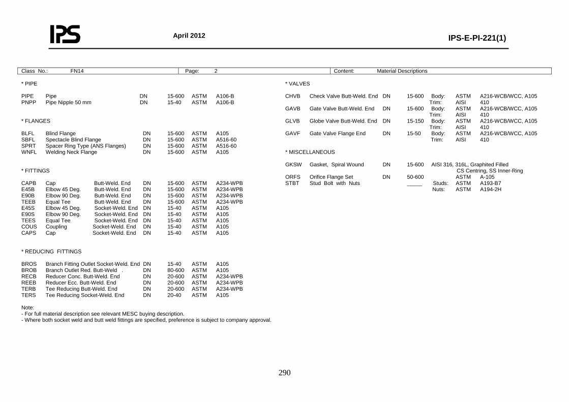
April 2012
IPS-E-PI-221(1)
290
Class No.: FN14 Page: 2 Content: Material Descriptions * PIPE PIPE Pipe DN 15-600 ASTM A106-B PNPP Pipe Nipple 50 mm DN 15-40 ASTM A106-B * FLANGES BLFL Blind Flange DN 15-600 ASTM A105 SBFL Spectacle Blind Flange DN 15-600 ASTM A516-60 SPRT Spacer Ring Type (ANS Flanges) DN 15-600 ASTM A516-60 WNFL Welding Neck Flange DN 15-600 ASTM A105 * FITTINGS CAPB Cap Butt-Weld. End DN 15-600 ASTM A234-WPB E45B Elbow 45 Deg. Butt-Weld. End DN 15-600 ASTM A234-WPB E90B Elbow 90 Deg. Butt-Weld. End DN 15-600 ASTM A234-WPB TEEB Equal Tee Butt-Weld. End DN 15-600 ASTM A234-WPB E45S Elbow 45 Deg. Socket-Weld. End DN 15-40 ASTM A105 E90S Elbow 90 Deg. Socket-Weld. End DN 15-40 ASTM A105 TEES Equal Tee Socket-Weld. End DN 15-40 ASTM A105 COUS Coupling Socket-Weld. End DN 15-40 ASTM A105 CAPS Cap Socket-Weld. End DN 15-40 ASTM A105 * REDUCING FITTINGS BROS Branch Fitting Outlet Socket-Weld. End DN 15-40 ASTM A105 BROB Branch Outlet Red. Butt-Weld . DN 80-600 ASTM A105 RECB Reducer Conc. Butt-Weld. End DN 20-600 ASTM A234-WPB REEB Reducer Ecc. Butt-Weld. End DN 20-600 ASTM A234-WPB TERB Tee Reducing Butt-Weld. End DN 20-600 ASTM A234-WPB TERS Tee Reducing Socket-Weld. End DN 20-40 ASTM A105 Note: - For full material description see relevant MESC buying description. - Where both socket weld and butt weld fittings are specified, preference is subject to company approval.
* VALVES CHVB Check Valve Butt-Weld. End DN 15-600 Body: ASTM A216-WCB/WCC, A105 Trim: AISI 410 GAVB Gate Valve Butt-Weld. End DN 15-600 Body: ASTM A216-WCB/WCC, A105 Trim: AISI 410 GLVB Globe Valve Butt-Weld. End DN 15-150 Body: ASTM A216-WCB/WCC, A105 Trim: AISI 410 GAVF Gate Valve Flange End DN 15-50 Body: ASTM A216-WCB/WCC, A105 Trim: AISI 410 * MISCELLANEOUS GKSW Gasket, Spiral Wound DN 15-600 AISI 316, 316L, Graphited Filled CS Centring, SS Inner-Ring ORFS Orifice Flange Set DN 50-600 ASTM A-105 STBT Stud Bolt with Nuts _____ Studs: ASTM A193-B7 Nuts: ASTM A194-2H
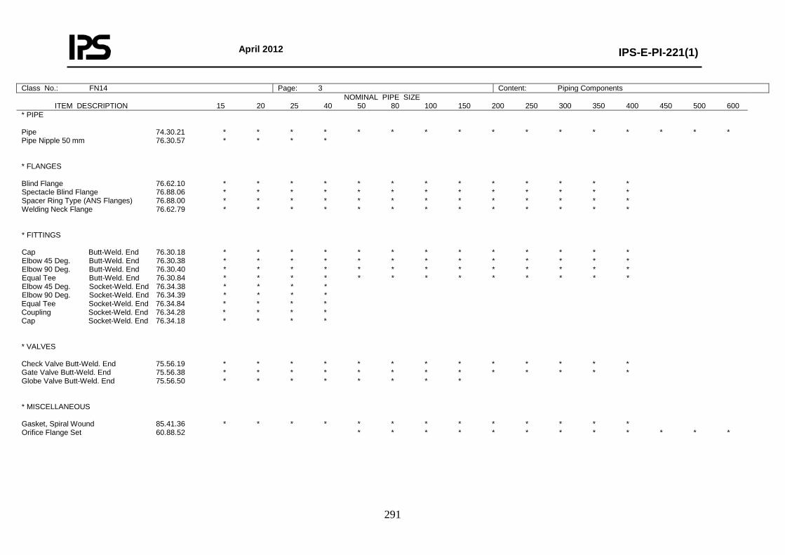
April 2012
IPS-E-PI-221(1)
291
Class No.: FN14 Page: 3 Content: Piping Components NOMINAL PIPE SIZE
ITEM DESCRIPTION 15 20 25 40 50 80 100 150 200 250 300 350 400 450 500 600
* PIPE Pipe 74.30.21 * * * * * * * * * * * * * * * * Pipe Nipple 50 mm 76.30.57 * * * * * FLANGES Blind Flange 76.62.10 * * * * * * * * * * * * * Spectacle Blind Flange 76.88.06 * * * * * * * * * * * * * Spacer Ring Type (ANS Flanges) 76.88.00 * * * * * * * * * * * * * Welding Neck Flange 76.62.79 * * * * * * * * * * * * * * FITTINGS Cap Butt-Weld. End 76.30.18 * * * * * * * * * * * * * Elbow 45 Deg. Butt-Weld. End 76.30.38 * * * * * * * * * * * * * Elbow 90 Deg. Butt-Weld. End 76.30.40 * * * * * * * * * * * * * Equal Tee Butt-Weld. End 76.30.84 * * * * * * * * * * * * * Elbow 45 Deg. Socket-Weld. End 76.34.38 * * * * Elbow 90 Deg. Socket-Weld. End 76.34.39 * * * * Equal Tee Socket-Weld. End 76.34.84 * * * * Coupling Socket-Weld. End 76.34.28 * * * * Cap Socket-Weld. End 76.34.18 * * * * * VALVES Check Valve Butt-Weld. End 75.56.19 * * * * * * * * * * * * * Gate Valve Butt-Weld. End 75.56.38 * * * * * * * * * * * * * Globe Valve Butt-Weld. End 75.56.50 * * * * * * * * * MISCELLANEOUS Gasket, Spiral Wound 85.41.36 * * * * * * * * * * * * * Orifice Flange Set 60.88.52 * * * * * * * * * * * *
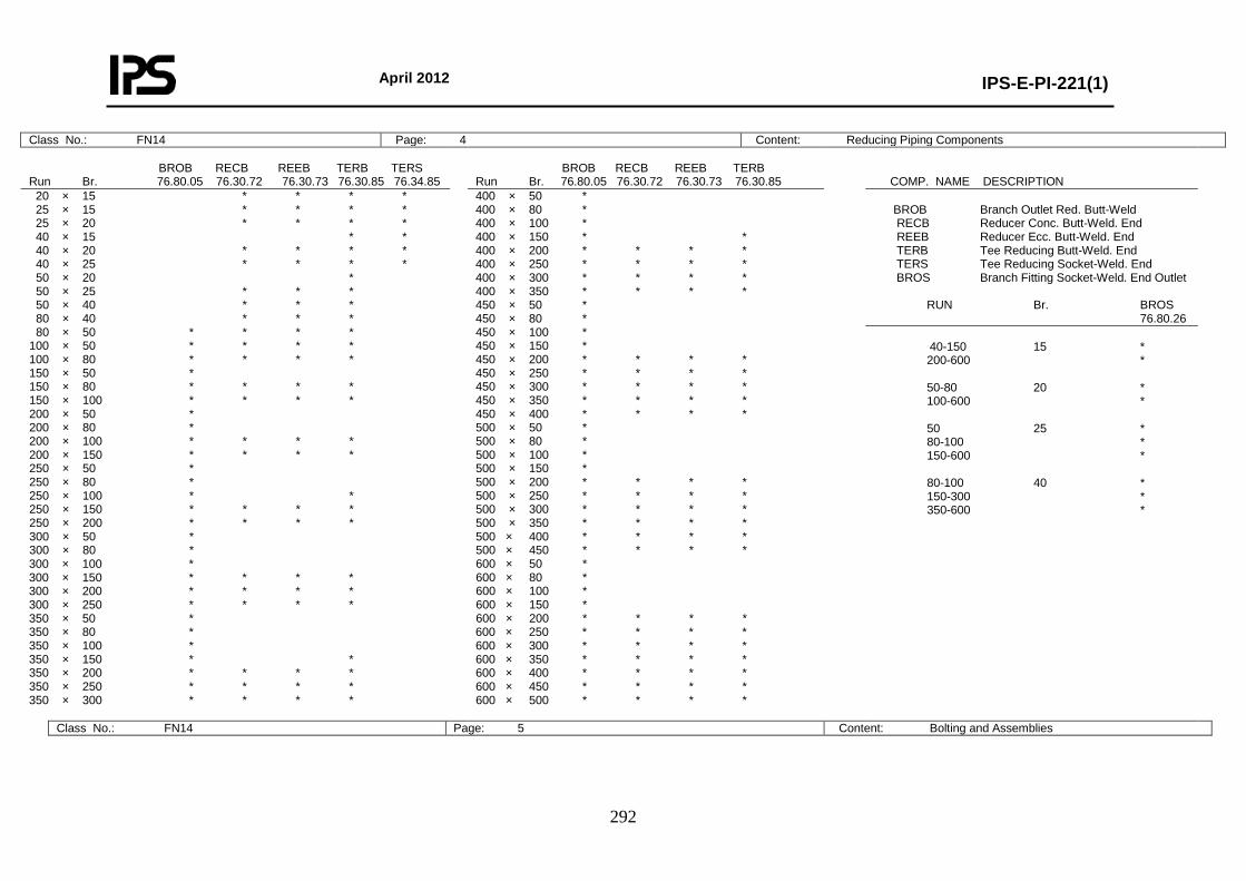
April 2012
IPS-E-PI-221(1)
292
Class No.: FN14 Page: 4 Content: Reducing Piping Components BROB RECB REEB TERB TERS Run Br. 76.80.05 76.30.72 76.30.73 76.30.85 76.34.85
BROB RECB REEB TERB Run Br. 76.80.05 76.30.72 76.30.73 76.30.85
COMP. NAME DESCRIPTION
20 × 15 * * * * 25 × 15 * * * * 25 × 20 * * * * 40 × 15 * * 40 × 20 * * * * 40 × 25 * * * * 50 × 20 * 50 × 25 * * * 50 × 40 * * * 80 × 40 * * * 80 × 50 * * * * 100 × 50 * * * * 100 × 80 * * * * 150 × 50 * 150 × 80 * * * * 150 × 100 * * * * 200 × 50 * 200 × 80 * 200 × 100 * * * * 200 × 150 * * * * 250 × 50 * 250 × 80 * 250 × 100 * * 250 × 150 * * * * 250 × 200 * * * * 300 × 50 * 300 × 80 * 300 × 100 * 300 × 150 * * * * 300 × 200 * * * * 300 × 250 * * * * 350 × 50 * 350 × 80 * 350 × 100 * 350 × 150 * * 350 × 200 * * * * 350 × 250 * * * * 350 × 300 * * * *
400 × 50 * 400 × 80 * 400 × 100 * 400 × 150 * * 400 × 200 * * * * 400 × 250 * * * * 400 × 300 * * * * 400 × 350 * * * * 450 × 50 * 450 × 80 * 450 × 100 * 450 × 150 * 450 × 200 * * * * 450 × 250 * * * * 450 × 300 * * * * 450 × 350 * * * * 450 × 400 * * * * 500 × 50 * 500 × 80 * 500 × 100 * 500 × 150 * 500 × 200 * * * * 500 × 250 * * * * 500 × 300 * * * * 500 × 350 * * * * 500 × 400 * * * * 500 × 450 * * * * 600 × 50 * 600 × 80 * 600 × 100 * 600 × 150 * 600 × 200 * * * * 600 × 250 * * * * 600 × 300 * * * * 600 × 350 * * * * 600 × 400 * * * * 600 × 450 * * * * 600 × 500 * * * *
BROB Branch Outlet Red. Butt-Weld RECB Reducer Conc. Butt-Weld. End REEB Reducer Ecc. Butt-Weld. End TERB Tee Reducing Butt-Weld. End TERS Tee Reducing Socket-Weld. End BROS Branch Fitting Socket-Weld. End Outlet RUN Br. BROS 76.80.26
40-150 15 * 200-600 * 50-80 20 * 100-600 * 50 25 * 80-100 * 150-600 * 80-100 40 * 150-300 * 350-600 *
Class No.: FN14 Page: 5 Content: Bolting and Assemblies
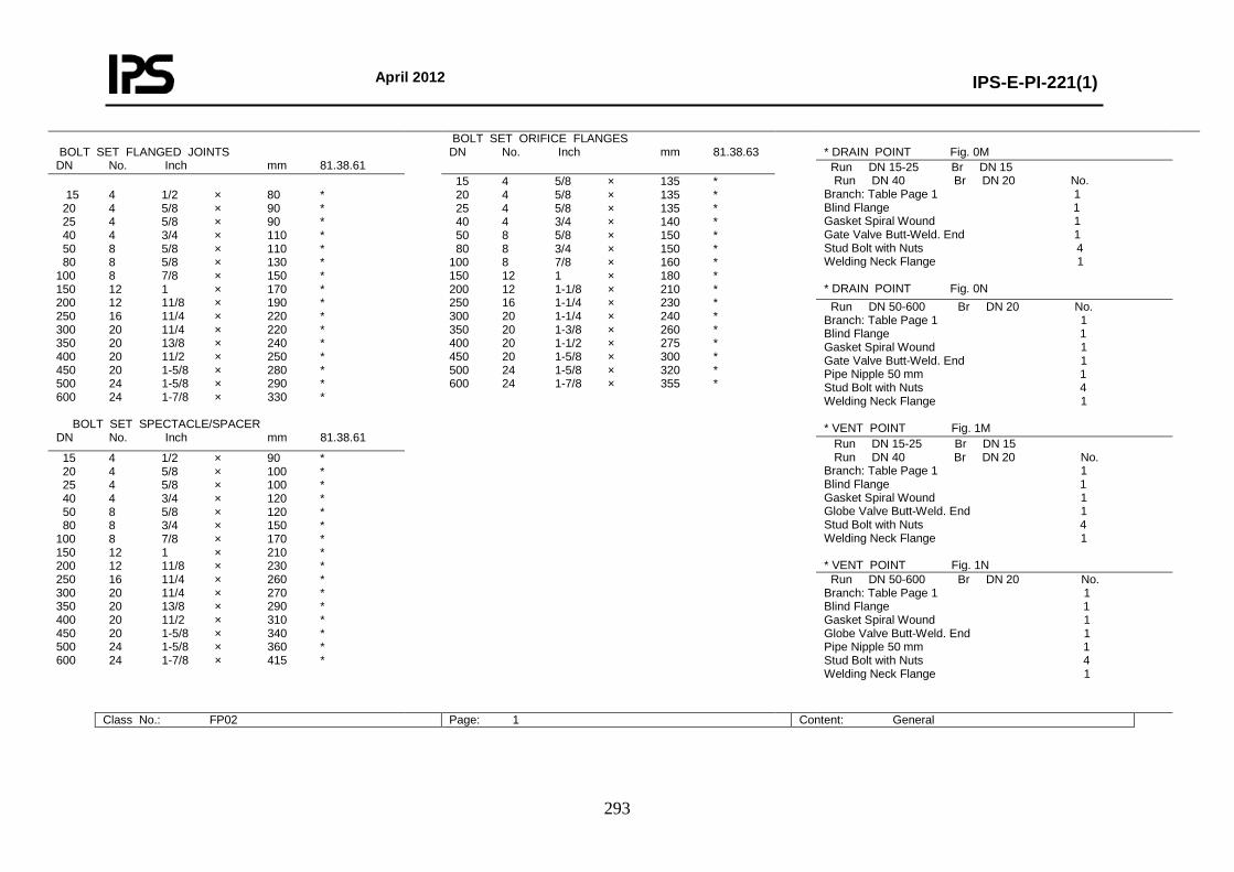
April 2012
IPS-E-PI-221(1)
293
BOLT SET FLANGED JOINTS DN No. Inch mm 81.38.61
BOLT SET ORIFICE FLANGES DN No. Inch mm 81.38.63
* DRAIN POINT Fig. 0M
Run DN 15-25 Br DN 15 Run DN 40 Br DN 20 No. Branch: Table Page 1 1 Blind Flange 1 Gasket Spiral Wound 1 Gate Valve Butt-Weld. End 1 Stud Bolt with Nuts 4 Welding Neck Flange 1 * DRAIN POINT Fig. 0N
15 4 1/2 × 80 * 20 4 5/8 × 90 * 25 4 5/8 × 90 * 40 4 3/4 × 110 * 50 8 5/8 × 110 * 80 8 5/8 × 130 * 100 8 7/8 × 150 * 150 12 1 × 170 * 200 12 11/8 × 190 * 250 16 11/4 × 220 * 300 20 11/4 × 220 * 350 20 13/8 × 240 * 400 20 11/2 × 250 * 450 20 1-5/8 × 280 * 500 24 1-5/8 × 290 * 600 24 1-7/8 × 330 * BOLT SET SPECTACLE/SPACER DN No. Inch mm 81.38.61
15 4 5/8 × 135 * 20 4 5/8 × 135 * 25 4 5/8 × 135 * 40 4 3/4 × 140 * 50 8 5/8 × 150 * 80 8 3/4 × 150 * 100 8 7/8 × 160 * 150 12 1 × 180 * 200 12 1-1/8 × 210 * 250 16 1-1/4 × 230 * 300 20 1-1/4 × 240 * 350 20 1-3/8 × 260 * 400 20 1-1/2 × 275 * 450 20 1-5/8 × 300 * 500 24 1-5/8 × 320 * 600 24 1-7/8 × 355 *
Run DN 50-600 Br DN 20 No. Branch: Table Page 1 1 Blind Flange 1 Gasket Spiral Wound 1 Gate Valve Butt-Weld. End 1 Pipe Nipple 50 mm 1 Stud Bolt with Nuts 4 Welding Neck Flange 1 * VENT POINT Fig. 1M Run DN 15-25 Br DN 15 Run DN 40 Br DN 20 No. Branch: Table Page 1 1 Blind Flange 1 Gasket Spiral Wound 1 Globe Valve Butt-Weld. End 1 Stud Bolt with Nuts 4 Welding Neck Flange 1 * VENT POINT Fig. 1N
15 4 1/2 × 90 * 20 4 5/8 × 100 * 25 4 5/8 × 100 * 40 4 3/4 × 120 * 50 8 5/8 × 120 * 80 8 3/4 × 150 * 100 8 7/8 × 170 * 150 12 1 × 210 * 200 12 11/8 × 230 * 250 16 11/4 × 260 * 300 20 11/4 × 270 * 350 20 13/8 × 290 * 400 20 11/2 × 310 * 450 20 1-5/8 × 340 * 500 24 1-5/8 × 360 * 600 24 1-7/8 × 415 *
Run DN 50-600 Br DN 20 No. Branch: Table Page 1 1 Blind Flange 1 Gasket Spiral Wound 1 Globe Valve Butt-Weld. End 1 Pipe Nipple 50 mm 1 Stud Bolt with Nuts 4 Welding Neck Flange 1
Class No.: FP02 Page: 1 Content: General
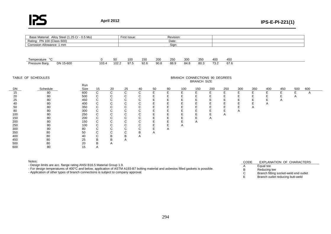
April 2012
IPS-E-PI-221(1)
294
Base Material: Alloy Steel (1.25 Cr - 0.5 Mo) First Issue: Revision: Rating: PN 100 (Class 600) Date: Corrosion Allowance: 1 mm Sign:
Temperature °C 0 50 100 150 200 250 300 350 400 450 Pressure Barg. DN 15-600 103.4 102.2 97.5 92.6 90.8 88.9 84.8 80.3 73.2 67.6
TABLE OF SCHEDULES
BRANCH CONNECTIONS 90 DEGREES
BRANCH SIZE
DN
Schedule Run
Size 15 20 25 40 50 80 100 150 200 250 300 350 400 450 500 600 15 20 25 40 50 80
100 150 200 250 300 350 400 450 500 600
80 80 80 80 80 80 80 80 80 80 80 80 80 80 80 80
600 C C C C E E E E E E E E E E E A 500 C C C C E E E E E E E E E E A 450 C C C C E E E E E E E E E A 400 C C C C E E E E E E E E A 350 C C C C E E E E E E E A 300 C C C C E E E E E E A 250 C C C C E E E E E A 200 C C C C E E E E A 150 C C C C E E E A 100 C C C C E E A 80 C C C C E A 50 C C C B A 40 C B B A 25 B B A 20 B A 15 A
Notes: - Design limits are acc. flange rating ANSI B16.5 Material Group 1.9. - For design temperatures of 400°C and below, application of ASTM A193-B7 bolting material and asbestos filled gaskets is possible. - Application of other types of branch connections is subject to company approval.
CODE EXPLANATION OF CHARACTERS A Equal tee B Reducing tee C Branch fitting socket-weld end outlet E Branch outlet reducing butt-weld

April 2012
IPS-E-PI-221(1)
295
Class No.: FP02 Page: 2 Content: Material Descriptions * PIPE PIPE Pipe DN 15-400 ASTM A335-P11 (Seamless) DN 450-600 ASTM A691-1.25CR (Welded) PNPP Pipe Nipple 50 mm DN 15-40 ASTM A335-P11 (Seamless) * FLANGES BLFL Blind Flange DN 15-600 ASTM A182-F11 SBFL Spectacle Blind Flange DN 15-600 ASTM A387-11 CL.2 SPRT Spacer Ring Type (ANS Flanges) DN 15-600 ASTM A387-11 CL.2 WNFL Welding Neck Flange DN 15-600 ASTM A182-F11 * FITTINGS CAPB Cap Butt-Weld. End DN 15-600 ASTM A234-WP11 E45B Elbow 45 Deg. Butt-Weld. End DN 15-600 ASTM A234-WP11 E90B Elbow 90 Deg. Butt-Weld. End DN 15-600 ASTM A234-WP11 TEEB Equal Tee Butt-Weld. End DN 15-600 ASTM A234-WP11 E45S Elbow 45 Deg. Socket-Weld. End DN 15-40 ASTM A182-F11 E90S Elbow 90 Deg. Socket-Weld. End DN 15-40 ASTM A182-F5 TEES Equal Tee Socket-Weld. End DN 15-40 ASTM A182-F5 COUS Coupling Socket-Weld. End DN 15-40 ASTM A182-F11 CAPS Cap Socket-Weld. End DN 15-40 ASTM A182-F11 * REDUCING FITTINGS BROS Branch Fitting Outlet Socket-Weld. End DN 15-40 ASTM A182-F11 BROB Branch Outlet Red. Butt-Weld. DN 80-600 ASTM A182-F11 RECB Reducer Conc. Butt-Weld. End DN 20-600 ASTM A234-WP11 REEB Reducer Ecc. Butt-Weld. End DN 20-600 ASTM A234-WP11 TERB Tee Reducing Butt-Weld. End DN 20-25 ASTM A234-WP11 TERS Tee Reducing Socket-Weld. End DN 20-40 ASTM A182-F11 Note: - For full material description see relevant MESC buying description. - Where both socket weld and butt weld fittings are specified, preference is subject to company approval.
* VALVES CHVB Check Valve Butt-Weld. End DN 15-400 Body: ASTM A217-WC6, A182-F11 Trim: AISI 316, 316L GAVB Gate Valve Butt-Weld. End DN 15-600 Body: ASTM A217-WC6, A182-F11 Trim: AISI 316, 316L GLVB Globe Valve Butt-Weld. End DN 15-150 Body: AASTM A217-WC6, A182-F11 Trim: AISI 316, 316L * MISCELLANEOUS GKSW Gasket, Spiral Wound DN 15-600 AISI 304, Graphite Filled, CS Centring-Ring, AISI 304 Inner R. ORFS Orifice Flange Set DN 50-600 ASTM A182-F11 STBT Stud Bolt with Nuts _____ Studs: ASTM A193-B16 Nuts: ASTM A194-4
Class No.: FP02 Page: 3 Content: Piping Components
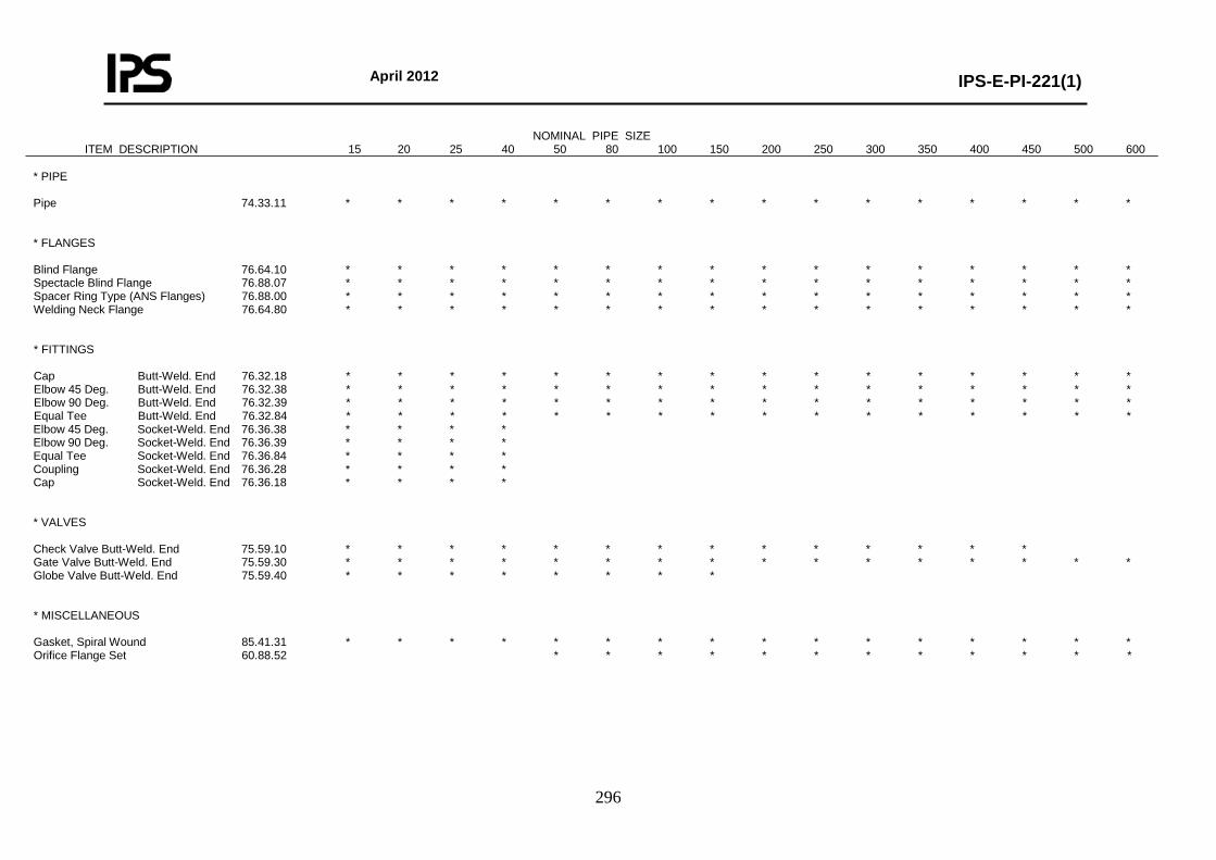
April 2012
IPS-E-PI-221(1)
296
NOMINAL PIPE SIZE ITEM DESCRIPTION 15 20 25 40 50 80 100 150 200 250 300 350 400 450 500 600
* PIPE Pipe 74.33.11 * * * * * * * * * * * * * * * * * FLANGES Blind Flange 76.64.10 * * * * * * * * * * * * * * * * Spectacle Blind Flange 76.88.07 * * * * * * * * * * * * * * * * Spacer Ring Type (ANS Flanges) 76.88.00 * * * * * * * * * * * * * * * * Welding Neck Flange 76.64.80 * * * * * * * * * * * * * * * * * FITTINGS Cap Butt-Weld. End 76.32.18 * * * * * * * * * * * * * * * * Elbow 45 Deg. Butt-Weld. End 76.32.38 * * * * * * * * * * * * * * * * Elbow 90 Deg. Butt-Weld. End 76.32.39 * * * * * * * * * * * * * * * * Equal Tee Butt-Weld. End 76.32.84 * * * * * * * * * * * * * * * * Elbow 45 Deg. Socket-Weld. End 76.36.38 * * * * Elbow 90 Deg. Socket-Weld. End 76.36.39 * * * * Equal Tee Socket-Weld. End 76.36.84 * * * * Coupling Socket-Weld. End 76.36.28 * * * * Cap Socket-Weld. End 76.36.18 * * * * * VALVES Check Valve Butt-Weld. End 75.59.10 * * * * * * * * * * * * * * Gate Valve Butt-Weld. End 75.59.30 * * * * * * * * * * * * * * * * Globe Valve Butt-Weld. End 75.59.40 * * * * * * * * * MISCELLANEOUS Gasket, Spiral Wound 85.41.31 * * * * * * * * * * * * * * * * Orifice Flange Set 60.88.52 * * * * * * * * * * * *
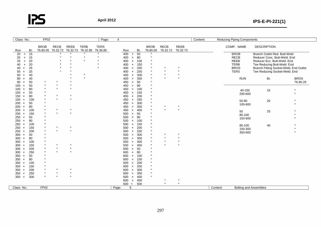
April 2012
IPS-E-PI-221(1)
297
Class No.: FP02 Page: 4 Content: Reducing Piping Components BROB RECB REEB TERB TERS Run Br. 76.80.05 76.32.72 76.32.73 76.32.85 76.36.85
BROB RECB REEB Run Br. 76.80.05 76.32.72 76.32.73
COMP. NAME DESCRIPTION
20 × 15 * * * * 25 × 15 * * * * 25 × 20 * * * * 40 × 20 * * * 40 × 25 * * * 50 × 25 * * 50 × 40 * * 80 × 40 * * 80 × 50 * * * 100 × 50 * * * 100 × 80 * * * 150 × 50 * 150 × 80 * * * 150 × 100 * * * 200 × 50 * 200 × 80 * 200 × 100 * * * 200 × 150 * * * 250 × 50 * 250 × 80 * 250 × 100 * 250 × 150 * * * 250 × 200 * * * 300 × 50 * 300 × 80 * 300 × 100 * 300 × 150 * * * 300 × 200 * * * 300 × 250 * * * 350 × 50 * 350 × 80 * 350 × 100 * 350 × 150 * 350 × 200 * * * 350 × 250 * * * 350 × 300 * * *
400 × 50 * 400 × 80 * 400 × 100 * 400 × 150 * 400 × 200 * * * 400 × 250 * * * 400 × 300 * * * 400 × 350 * * * 450 × 50 * 450 × 80 * 450 × 100 * 450 × 150 * 450 × 200 * 450 × 250 * 450 × 300 * 450 × 350 * * * 450 × 400 * * * 500 × 50 * 500 × 80 * 500 × 100 * 500 × 150 * 500 × 200 * 500 × 250 * 500 × 300 * * * 500 × 350 * * * 500 × 400 * * * 500 × 450 * * * 600 × 50 * 600 × 80 * 600 × 100 * 600 × 150 * 600 × 200 * 600 × 250 * 600 × 300 * 600 × 350 * 600 × 400 * 600 × 450 * * 600 × 500 * *
BROB Branch Outlet Red. Butt-Weld RECB Reducer Conc. Butt-Weld. End REEB Reducer Ecc. Butt-Weld. End TERB Tee Reducing Butt-Weld. End BROS Branch Fitting Socket-Weld. End Outlet TERS Tee Reducing Socket-Weld. End RUN Br. BROS 76.80.26
40-150 15 * 200-600 * 50-80 20 * 100-600 * 50 25 * 80-100 * 150-600 * 80-100 40 * 150-300 * 350-600 *
Class No.: FP02 Page: 5 Content: Bolting and Assemblies
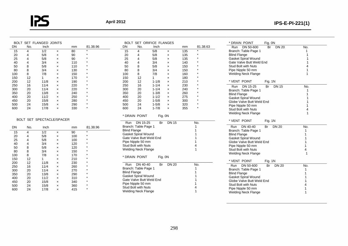
April 2012
IPS-E-PI-221(1)
298
BOLT SET FLANGED JOINTS DN No. Inch mm 81.38.96
BOLT SET ORIFICE FLANGES DN No. Inch mm 81.38.63
* DRAIN POINT Fig. 0N
Run DN 50-600 Br DN 20 No. Branch: Table Page 1 1 Blind Flange 1 Gasket Spiral Wound 1 Gate Valve Butt Weld End 1 Stud Bolt with Nuts 4 Pipe Nipple 50 mm 1 Welding Neck Flange 1 * VENT POINT Fig. 1N
15 4 1/2 × 80 * 20 4 5/8 × 90 * 25 4 5/8 × 90 * 40 4 3/4 × 110 * 50 8 5/8 × 110 * 80 8 3/4 × 130 * 100 8 7/8 × 150 * 150 12 1 × 170 * 200 12 11/8 × 190 * 250 16 11/4 × 220 * 300 20 11/4 × 220 * 350 20 13/8 × 240 * 400 20 11/2 × 250 * 450 20 15/8 × 280 * 500 24 15/8 × 290 * 600 24 17/8 × 330 * BOLT SET SPECTACLE/SPACER DN No. Inch mm 81.38.96
15 4 5/8 × 135 * 20 4 5/8 × 135 * 25 4 5/8 × 135 * 40 4 3/4 × 140 * 50 8 5/8 × 150 * 80 8 3/4 × 150 * 100 8 7/8 × 160 * 150 12 1 × 180 * 200 12 1-1/8 × 210 * 250 16 1-1/4 × 230 * 300 20 1-1/4 × 240 * 350 20 1-3/8 × 260 * 400 20 1-1/2 × 275 * 450 20 1-5/8 × 300 * 500 24 1-5/8 × 320 * 600 24 1-7/8 × 355 * * DRAIN POINT Fig. 0N
Run DN 15-25 Br DN 15 No. Branch: Table Page 1 1 Blind Flange 1 Gasket Spiral Wound 1 Globe Valve Butt Weld End 1 Pipe Nipple 50 mm 1 Stud Bolt with Nuts 4 Welding Neck Flange 1 * VENT POINT Fig. 1N Run DN 15-25 Br DN 15 No.
Branch: Table Page 1 1 Blind Flange 1 Gasket Spiral Wound 1 Gate Valve Butt Weld End 1 Pipe Nipple 50 mm 1 Stud Bolt with Nuts 4 Welding Neck Flange 1 * DRAIN POINT Fig. 0N _________________________________________________ Run DN 40-40 Br DN 20 No. Branch: Table Page 1 1 Blind Flange 1 Gasket Spiral Wound 1 Gate Valve Butt Weld End 1 Pipe Nipple 50 mm 1 Stud Bolt with Nuts 4 Welding Neck Flange 1
Run DN 40-40 Br DN 20 No. Branch: Table Page 1 1 Blind Flange 1 Gasket Spiral Wound 1 Globe Valve Butt Weld End 1 Pipe Nipple 50 mm 1 Stud Bolt with Nuts 4 Welding Neck Flange 1 * VENT POINT Fig. 1N
15 4 1/2 × 90 * 20 4 5/8 × 100 * 25 4 5/8 × 100 * 40 4 3/4 × 120 * 50 8 5/8 × 120 * 80 8 3/4 × 150 * 100 8 7/8 × 170 * 150 12 1 × 210 * 200 12 11/8 × 230 * 250 16 11/4 × 260 * 300 20 11/4 × 270 * 350 20 13/8 × 290 * 400 20 11/2 × 310 * 450 20 15/8 × 340 * 500 24 15/8 × 360 * 600 24 17/8 × 415 *
Run DN 50-600 Br DN 20 No. Branch: Table Page 1 1 Blind Flange 1 Gasket Spiral Wound 1 Globe Valve Butt Weld End 1 Stud Bolt with Nuts 4 Pipe Nipple 50 mm 1 Welding Neck Flange 1
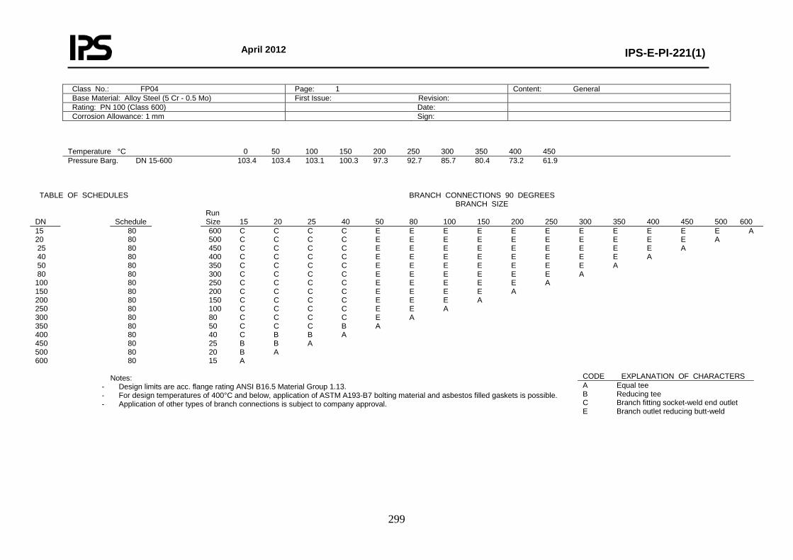
April 2012
IPS-E-PI-221(1)
299
Class No.: FP04 Page: 1 Content: General Base Material: Alloy Steel (5 Cr - 0.5 Mo) First Issue: Revision: Rating: PN 100 (Class 600) Date: Corrosion Allowance: 1 mm Sign:
Temperature °C 0 50 100 150 200 250 300 350 400 450 Pressure Barg. DN 15-600 103.4 103.4 103.1 100.3 97.3 92.7 85.7 80.4 73.2 61.9
TABLE OF SCHEDULES
BRANCH CONNECTIONS 90 DEGREES
BRANCH SIZE DN
Schedule
Run Size 15 20 25 40 50 80 100 150 200 250 300 350 400 450 500 600
15 20 25 40 50 80 100 150 200 250 300 350 400 450 500 600
80 80 80 80 80 80 80 80 80 80 80 80 80 80 80 80
600 C C C C E E E E E E E E E E E A 500 C C C C E E E E E E E E E E A 450 C C C C E E E E E E E E E A 400 C C C C E E E E E E E E A 350 C C C C E E E E E E E A 300 C C C C E E E E E E A 250 C C C C E E E E E A 200 C C C C E E E E A 150 C C C C E E E A 100 C C C C E E A 80 C C C C E A 50 C C C B A 40 C B B A 25 B B A 20 B A 15 A
Notes: - Design limits are acc. flange rating ANSI B16.5 Material Group 1.13. - For design temperatures of 400°C and below, application of ASTM A193-B7 bolting material and asbestos filled gaskets is possible. - Application of other types of branch connections is subject to company approval.
CODE EXPLANATION OF CHARACTERS A Equal tee B Reducing tee C Branch fitting socket-weld end outlet E Branch outlet reducing butt-weld
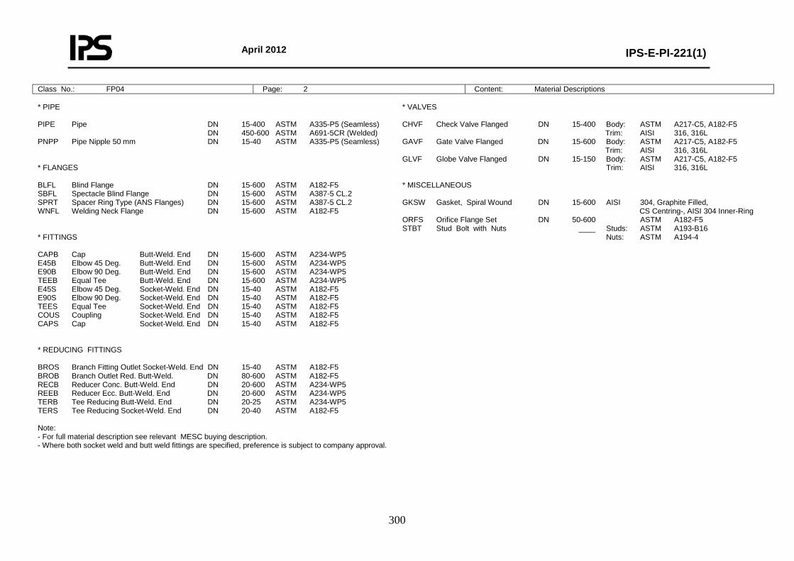
April 2012
IPS-E-PI-221(1)
300
Class No.: FP04 Page: 2 Content: Material Descriptions * PIPE PIPE Pipe DN 15-400 ASTM A335-P5 (Seamless) DN 450-600 ASTM A691-5CR (Welded) PNPP Pipe Nipple 50 mm DN 15-40 ASTM A335-P5 (Seamless) * FLANGES BLFL Blind Flange DN 15-600 ASTM A182-F5 SBFL Spectacle Blind Flange DN 15-600 ASTM A387-5 CL.2 SPRT Spacer Ring Type (ANS Flanges) DN 15-600 ASTM A387-5 CL.2 WNFL Welding Neck Flange DN 15-600 ASTM A182-F5 * FITTINGS CAPB Cap Butt-Weld. End DN 15-600 ASTM A234-WP5 E45B Elbow 45 Deg. Butt-Weld. End DN 15-600 ASTM A234-WP5 E90B Elbow 90 Deg. Butt-Weld. End DN 15-600 ASTM A234-WP5 TEEB Equal Tee Butt-Weld. End DN 15-600 ASTM A234-WP5 E45S Elbow 45 Deg. Socket-Weld. End DN 15-40 ASTM A182-F5 E90S Elbow 90 Deg. Socket-Weld. End DN 15-40 ASTM A182-F5 TEES Equal Tee Socket-Weld. End DN 15-40 ASTM A182-F5 COUS Coupling Socket-Weld. End DN 15-40 ASTM A182-F5 CAPS Cap Socket-Weld. End DN 15-40 ASTM A182-F5 * REDUCING FITTINGS BROS Branch Fitting Outlet Socket-Weld. End DN 15-40 ASTM A182-F5 BROB Branch Outlet Red. Butt-Weld. DN 80-600 ASTM A182-F5 RECB Reducer Conc. Butt-Weld. End DN 20-600 ASTM A234-WP5 REEB Reducer Ecc. Butt-Weld. End DN 20-600 ASTM A234-WP5 TERB Tee Reducing Butt-Weld. End DN 20-25 ASTM A234-WP5 TERS Tee Reducing Socket-Weld. End DN 20-40 ASTM A182-F5 Note: - For full material description see relevant MESC buying description. - Where both socket weld and butt weld fittings are specified, preference is subject to company approval.
* VALVES CHVF Check Valve Flanged DN 15-400 Body: ASTM A217-C5, A182-F5 Trim: AISI 316, 316L GAVF Gate Valve Flanged DN 15-600 Body: ASTM A217-C5, A182-F5 Trim: AISI 316, 316L GLVF Globe Valve Flanged DN 15-150 Body: ASTM A217-C5, A182-F5 Trim: AISI 316, 316L * MISCELLANEOUS GKSW Gasket, Spiral Wound DN 15-600 AISI 304, Graphite Filled, CS Centring-, AISI 304 Inner-Ring ORFS Orifice Flange Set DN 50-600 ASTM A182-F5 STBT Stud Bolt with Nuts ____ Studs: ASTM A193-B16 Nuts: ASTM A194-4
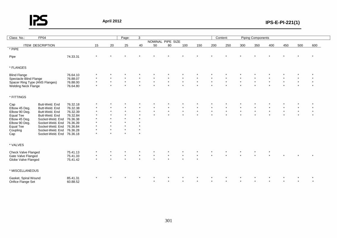
April 2012
IPS-E-PI-221(1)
301
Class No.: FP04 Page: 3 Content: Piping Components NOMINAL PIPE SIZE
ITEM DESCRIPTION 15 20 25 40 50 80 100 150 200 250 300 350 400 450 500 600
* PIPE Pipe 74.33.31 * * * * * * * * * * * * * * * * * FLANGES Blind Flange 76.64.10 * * * * * * * * * * * * * * * * Spectacle Blind Flange 76.88.07 * * * * * * * * * * * * * * * * Spacer Ring Type (ANS Flanges) 76.88.00 * * * * * * * * * * * * * * * * Welding Neck Flange 76.64.80 * * * * * * * * * * * * * * * * * FITTINGS Cap Butt-Weld. End 76.32.18 * * * * * * * * * * * * * * * * Elbow 45 Deg. Butt-Weld. End 76.32.38 * * * * * * * * * * * * * * * * Elbow 90 Deg. Butt-Weld. End 76.32.39 * * * * * * * * * * * * * * * * Equal Tee Butt-Weld. End 76.32.84 * * * * * * * * * * * * * * * * Elbow 45 Deg. Socket-Weld. End 76.36.38 * * * * Elbow 90 Deg. Socket-Weld. End 76.36.39 * * * * Equal Tee Socket-Weld. End 76.36.84 * * * * Coupling Socket-Weld. End 76.36.28 * * * * Cap Socket-Weld. End 76.36.18 * * * * * VALVES Check Valve Flanged 75.41.13 * * * * * * * * * * * * * Gate Valve Flanged 75.41.33 * * * * * * * * * * * * * * * * Globe Valve Flanged 75.41.42 * * * * * * * * * MISCELLANEOUS Gasket, Spiral Wound 85.41.31 * * * * * * * * * * * * * * * * Orifice Flange Set 60.88.52 * * * * * * * * * * * *
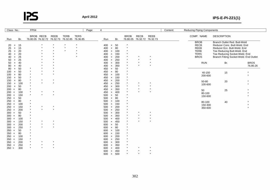
April 2012
IPS-E-PI-221(1)
302
Class No.: FP04 Page: 4 Content: Reducing Piping Components BROB RECB REEB TERB TERS Run Br. 76.80.05 76.32.72 76.32.73 76.32.85 76.36.85
BROB RECB REEB Run Br. 76.80.05 76.32.72 76.32.73
COMP. NAME DESCRIPTION
20 × 15 * * * * 25 × 15 * * * * 25 × 20 * * * * 40 × 20 * * * 40 × 25 * * * 50 × 25 * * 50 × 40 * * 80 × 40 * * 80 × 50 * * * 100 × 50 * * * 100 × 80 * * * 150 × 50 * 150 × 80 * * * 150 × 100 * * * 200 × 50 * 200 × 80 * 200 × 100 * * * 200 × 150 * * * 250 × 50 250 × 80 * 250 × 100 * 250 × 150 * * * 250 × 200 * * * 300 × 50 * 300 × 80 * 300 × 100 * 300 × 150 * * * 300 × 200 * * * 300 × 250 * * * 350 × 50 * 350 × 80 * 350 × 100 * 350 × 150 * 350 × 200 * * * 350 × 250 * * * 350 × 300 * * *
400 × 50 * 400 × 80 * 400 × 100 * 400 × 150 * 400 × 200 * * * 400 × 250 * * * 400 × 300 * * * 400 × 350 * * * 450 × 50 * 450 × 80 * 450 × 100 * 450 × 150 * 450 × 200 * 450 × 250 * * * 450 × 300 * * * 450 × 350 * * * 450 × 400 * * * 500 × 50 * 500 × 80 * 500 × 100 * 500 × 150 * 500 × 200 * 500 × 250 * 500 × 300 * * * 500 × 350 * * * 500 × 400 * * * 500 × 450 * * * 600 × 50 * 600 × 80 * 600 × 100 * 600 × 150 * 600 × 200 * 600 × 250 * 600 × 300 * 600 × 350 * 600 × 400 * * * 600 × 450 * * * 600 × 500 * * *
BROB Branch Outlet Red. Butt-Weld RECB Reducer Conc. Butt-Weld. End REEB Reducer Ecc. Butt-Weld. End TERB Tee Reducing Butt-Weld. End TERS Tee Reducing Socket-Weld. End BROS Branch Fitting Socket-Weld. End Outlet RUN Br. BROS 76.80.26
40-150 15 * 200-600 * 50-80 20 * 100-600 * 50 25 * 80-100 * 150-600 * 80-100 40 * 150-300 * 350-600 *
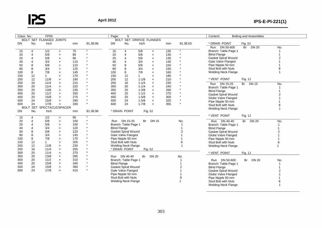
April 2012
IPS-E-PI-221(1)
303
Class No.: FP04 Page: 5 Content: Bolting and Assemblies BOLT SET FLANGED JOINTS DN No. Inch mm 81.38.96
BOLT SET ORIFICE FLANGES DN No. Inch mm 81.38.63
* DRAIN POINT Fig. 0J
Run DN 50-600 Br DN 20 No. Branch: Table Page 1 1 Blind Flange 1 Gasket Spiral Wound 2 Gate Valve Flanged 1 Pipe Nipple 50 mm 1 Stud Bolt with Nuts 8 Welding Neck Flange 1 * VENT POINT Fig. 1J
15 4 1/2 × 75 * 20 4 5/8 × 85 * 25 4 5/8 × 90 * 40 4 3/4 × 110 * 50 8 5/8 × 110 * 80 8 3/4 × 125 * 100 8 7/8 × 145 * 150 12 1 × 170 * 200 12 11/8 × 190 * 250 16 11/4 × 215 * 300 20 11/4 × 220 * 350 20 13/8 × 235 * 400 20 11/2 × 250 * 450 20 15/8 × 275 * 500 24 15/8 × 290 * 600 24 17/8 × 330 * BOLT SET SPECTACLE/SPACER DN No. Inch mm 81.38.96
15 4 5/8 × 135 * 20 4 5/8 × 135 * 25 4 5/8 × 135 * 40 4 3/4 × 140 * 50 8 5/8 × 150 * 80 8 3/4 × 150 * 100 8 7/8 × 160 * 150 12 1 × 180 * 200 12 1-1/8 × 210 * 250 16 1-1/4 × 230 * 300 20 1-1/4 × 240 * 350 20 1-3/8 × 260 * 400 20 1-1/2 × 275 * 450 20 1-5/8 × 300 * 500 24 1-5/8 × 320 * 600 24 1-7/8 × 355 * * DRAIN POINT Fig. 0J
Run DN 15-25 Br DN 15 No. Branch: Table Page 1 1 Blind Flange 1 Gasket Spiral Wound 2 Globe Valve Flanged 1 Pipe Nipple 50 mm 1 Stud Bolt with Nuts 8 Welding Neck Flange 1 * VENT POINT Fig. 1J 15 4 1/2 × 90 *
20 4 5/8 × 100 * 25 4 5/8 × 100 * 40 4 3/4 × 120 * 50 8 5/8 × 120 * 80 8 3/4 × 145 * 100 8 7/8 × 170 * 150 12 1 × 205 * 200 12 11/8 × 230 * 250 16 11/4 × 255 * 300 20 11/4 × 270 * 350 20 13/8 × 285 * 400 20 11/2 × 310 * 450 20 15/8 × 340 * 500 24 15/8 × 360 * 600 24 17/8 × 415 *
Run DN 15-25 Br DN 15 No. Branch: Table Page 1 1 Blind Flange 1 Gasket Spiral Wound 2 Gate Valve Flanged 1 Pipe Nipple 50 mm 1 Stud Bolt with Nuts 8 Welding Neck Flange 1 * DRAIN POINT Fig. 0J
Run DN 40-40 Br DN 20 No. Branch: Table Page 1 1 Blind Flange 1 Gasket Spiral Wound 2 Globe Valve Flanged 1 Pipe Nipple 50 mm 1 Stud Bolt with Nuts 8 Welding Neck Flange 1 * VENT POINT Fig. 1J
Run DN 40-40 Br DN 20 No. Branch: Table Page 1 1 Blind Flange 1 Gasket Spiral Wound 2 Gate Valve Flanged 1 Pipe Nipple 50 mm 1 Stud Bolt with Nuts 8 Welding Neck Flange 1
Run DN 50-600 Br DN 20 No. Branch: Table Page 1 1 Blind Flange 1 Gasket Spiral Wound 2 Globe Valve Flanged 1 Pipe Nipple 50 mm 1 Stud Bolt with Nuts 8 Welding Neck Flange 1
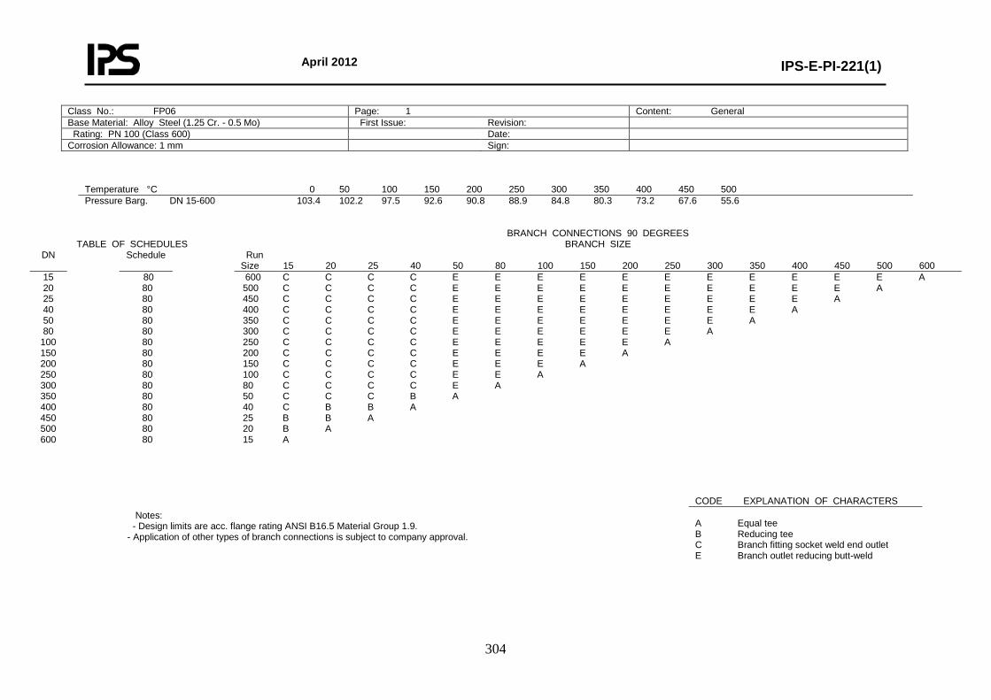
April 2012
IPS-E-PI-221(1)
304
Class No.: FP06 Page: 1 Content: General Base Material: Alloy Steel (1.25 Cr. - 0.5 Mo) First Issue: Revision: Rating: PN 100 (Class 600) Date: Corrosion Allowance: 1 mm Sign:
Temperature °C 0 50 100 150 200 250 300 350 400 450 500 Pressure Barg. DN 15-600 103.4 102.2 97.5 92.6 90.8 88.9 84.8 80.3 73.2 67.6 55.6
TABLE OF SCHEDULES BRANCH CONNECTIONS 90 DEGREES
BRANCH SIZE DN Schedule Run
Size 15 20 25 40 50 80 100 150 200 250 300 350 400 450 500 600 15 20 25 40 50 80
100 150 200 250 300 350 400 450 500 600
80 80 80 80 80 80 80 80 80 80 80 80 80 80 80 80
600 C C C C E E E E E E E E E E E A 500 C C C C E E E E E E E E E E A 450 C C C C E E E E E E E E E A 400 C C C C E E E E E E E E A 350 C C C C E E E E E E E A 300 C C C C E E E E E E A 250 C C C C E E E E E A 200 C C C C E E E E A 150 C C C C E E E A 100 C C C C E E A 80 C C C C E A 50 C C C B A 40 C B B A 25 B B A 20 B A 15 A
Notes: - Design limits are acc. flange rating ANSI B16.5 Material Group 1.9. - Application of other types of branch connections is subject to company approval.
CODE EXPLANATION OF CHARACTERS A Equal tee B Reducing tee C Branch fitting socket weld end outlet E Branch outlet reducing butt-weld
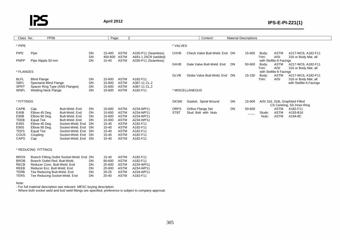
April 2012
IPS-E-PI-221(1)
305
Class No.: FP06 Page: 2 Content: Material Descriptions * PIPE PIPE Pipe DN 15-400 ASTM A335-P11 (Seamless) DN 450-600 ASTM A691-1.25CR (welded) PNPP Pipe Nipple 50 mm DN 15-40 ASTM A335-P11 (Seamless) * FLANGES BLFL Blind Flange DN 15-600 ASTM A182-F11 SBFL Spectacle Blind Flange DN 15-600 ASTM A387-11 CL.2 SPRT Spacer Ring Type (ANS Flanges) DN 15-600 ASTM A387-11 CL.2 WNFL Welding Neck Flange DN 15-600 ASTM A182-F11 * FITTINGS CAPB Cap Butt-Weld. End DN 15-600 ASTM A234-WP11 E45B Elbow 45 Deg. Butt-Weld. End DN 15-600 ASTM A234-WP11 E90B Elbow 90 Deg. Butt-Weld. End DN 15-600 ASTM A234-WP11 TEEB Equal Tee Butt-Weld. End DN 15-600 ASTM A234-WP11 E45S Elbow 45 Deg. Socket-Weld. End DN 15-40 ASTM A182-F11 E90S Elbow 90 Deg. Socket-Weld. End DN 15-40 ASTM A182-F11 TEES Equal Tee Socket-Weld. End DN 15-40 ASTM A182-F11 COUS Coupling Socket-Weld. End DN 15-40 ASTM A182-F11 CAPS Cap Socket-Weld. End DN 15-40 ASTM A182-F11 * REDUCING FITTINGS BROS Branch Fitting Outlet Socket-Weld. End DN 15-40 ASTM A182-F11 BROB Branch Outlet Red. Butt-Weld. DN 80-600 ASTM A182-F11 RECB Reducer Conc. Butt-Weld. End DN 20-600 ASTM A234-WP11 REEB Reducer Ecc. Butt-Weld. End DN 20-600 ASTM A234-WP11 TERB Tee Reducing Butt-Weld. End DN 20-25 ASTM A234-WP11 TERS Tee Reducing Socket-Weld. End DN 20-40 ASTM A182-F11 Note: - For full material description see relevant MESC buying description. - Where both socket weld and butt weld fittings are specified, preference is subject to company approval.
* VALVES CHVB Check Valve Butt-Weld. End DN 15-600 Body: ASTM A217-WC6, A182-F11 Trim: AISI 316 or Body Mat. all with Stellite-6 Facings GAVB Gate Valve Butt-Weld. End DN 50-600 Body: ASTM A217-WC6, A182-F11 Trim: AISI 316 or Body Mat. all with Stellite-6 Facings GLVB Globe Valve Butt-Weld. End DN 15-150 Body: ASTM A217-WC6, A182-F11 Trim: AISI 316 or Body Mat. all with Stellite-6 Facings * MISCELLANEOUS GKSW Gasket, Spiral Wound DN 15-600 AISI 316, 316L Graphited Filled CS Centring, SS Inner-Ring ORFS Orifice Flange Set DN 50-600 ASTM A182-F11 STBT Stud Bolt with Nuts ____ Studs: ASTM A193-B16 Nuts: ASTM A194-8C
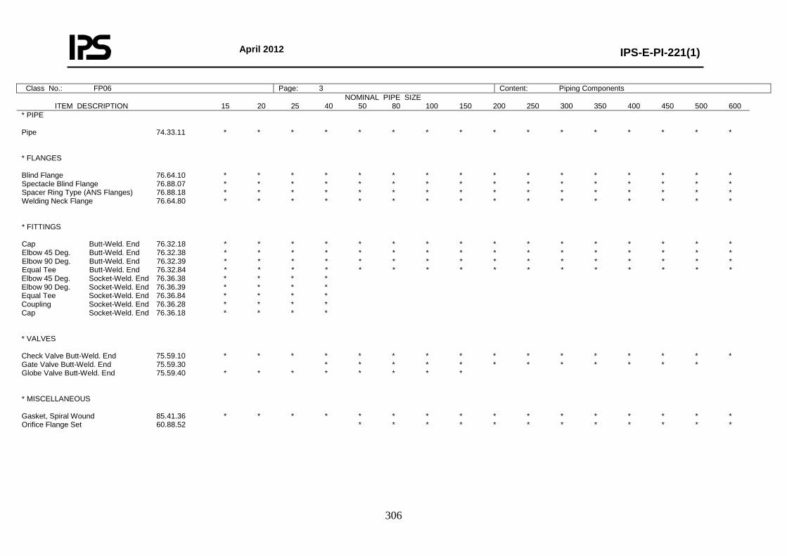
April 2012
IPS-E-PI-221(1)
306
Class No.: FP06 Page: 3 Content: Piping Components NOMINAL PIPE SIZE
ITEM DESCRIPTION 15 20 25 40 50 80 100 150 200 250 300 350 400 450 500 600
* PIPE Pipe 74.33.11 * * * * * * * * * * * * * * * * * FLANGES Blind Flange 76.64.10 * * * * * * * * * * * * * * * * Spectacle Blind Flange 76.88.07 * * * * * * * * * * * * * * * * Spacer Ring Type (ANS Flanges) 76.88.18 * * * * * * * * * * * * * * * * Welding Neck Flange 76.64.80 * * * * * * * * * * * * * * * * * FITTINGS Cap Butt-Weld. End 76.32.18 * * * * * * * * * * * * * * * * Elbow 45 Deg. Butt-Weld. End 76.32.38 * * * * * * * * * * * * * * * * Elbow 90 Deg. Butt-Weld. End 76.32.39 * * * * * * * * * * * * * * * * Equal Tee Butt-Weld. End 76.32.84 * * * * * * * * * * * * * * * * Elbow 45 Deg. Socket-Weld. End 76.36.38 * * * * Elbow 90 Deg. Socket-Weld. End 76.36.39 * * * * Equal Tee Socket-Weld. End 76.36.84 * * * * Coupling Socket-Weld. End 76.36.28 * * * * Cap Socket-Weld. End 76.36.18 * * * * * VALVES Check Valve Butt-Weld. End 75.59.10 * * * * * * * * * * * * * * * * Gate Valve Butt-Weld. End 75.59.30 * * * * * * * * * * * * Globe Valve Butt-Weld. End 75.59.40 * * * * * * * * * MISCELLANEOUS Gasket, Spiral Wound 85.41.36 * * * * * * * * * * * * * * * * Orifice Flange Set 60.88.52 * * * * * * * * * * * *
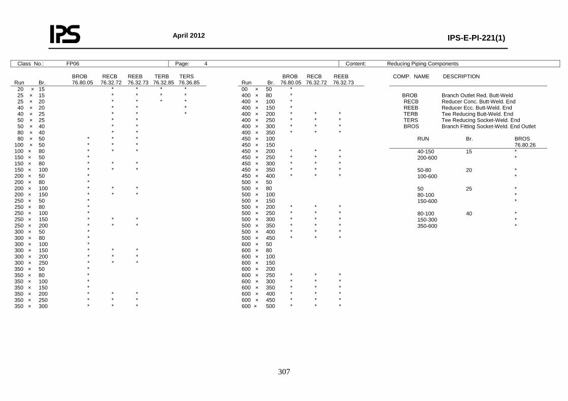
April 2012
IPS-E-PI-221(1)
307
Class No.: FP06 Page: 4 Content: Reducing Piping Components BROB RECB REEB TERB TERS Run Br. 76.80.05 76.32.72 76.32.73 76.32.85 76.36.85
BROB RECB REEB Run Br. 76.80.05 76.32.72 76.32.73
COMP. NAME DESCRIPTION
20 × 15 * * * * 25 × 15 * * * * 25 × 20 * * * * 40 × 20 * * * 40 × 25 * * * 50 × 25 * * 50 × 40 * * 80 × 40 * * 80 × 50 * * * 100 × 50 * * * 100 × 80 * * * 150 × 50 * 150 × 80 * * * 150 × 100 * * * 200 × 50 * 200 × 80 * 200 × 100 * * * 200 × 150 * * * 250 × 50 * 250 × 80 * 250 × 100 * 250 × 150 * * * 250 × 200 * * * 300 × 50 * 300 × 80 * 300 × 100 * 300 × 150 * * * 300 × 200 * * * 300 × 250 * * * 350 × 50 * 350 × 80 * 350 × 100 * 350 × 150 * 350 × 200 * * * 350 × 250 * * * 350 × 300 * * *
00 × 50 * 400 × 80 * 400 × 100 * 400 × 150 * 400 × 200 * * * 400 × 250 * * * 400 × 300 * * * 400 × 350 * * * 450 × 100 450 × 150 450 × 200 * * * 450 × 250 * * * 450 × 300 * * * 450 × 350 * * * 450 × 400 * * * 500 × 50 500 × 80 500 × 100 500 × 150 500 × 200 * * * 500 × 250 * * * 500 × 300 * * * 500 × 350 * * * 500 × 400 * * * 500 × 450 * * * 600 × 50 600 × 80 600 × 100 600 × 150 600 × 200 600 × 250 * * * 600 × 300 * * * 600 × 350 * * * 600 × 400 * * * 600 × 450 * * * 600 × 500 * * *
BROB Branch Outlet Red. Butt-Weld RECB Reducer Conc. Butt-Weld. End REEB Reducer Ecc. Butt-Weld. End TERB Tee Reducing Butt-Weld. End TERS Tee Reducing Socket-Weld. End BROS Branch Fitting Socket-Weld. End Outlet RUN Br. BROS 76.80.26
40-150 15 * 200-600 * 50-80 20 * 100-600 * 50 25 * 80-100 * 150-600 * 80-100 40 * 150-300 * 350-600 *
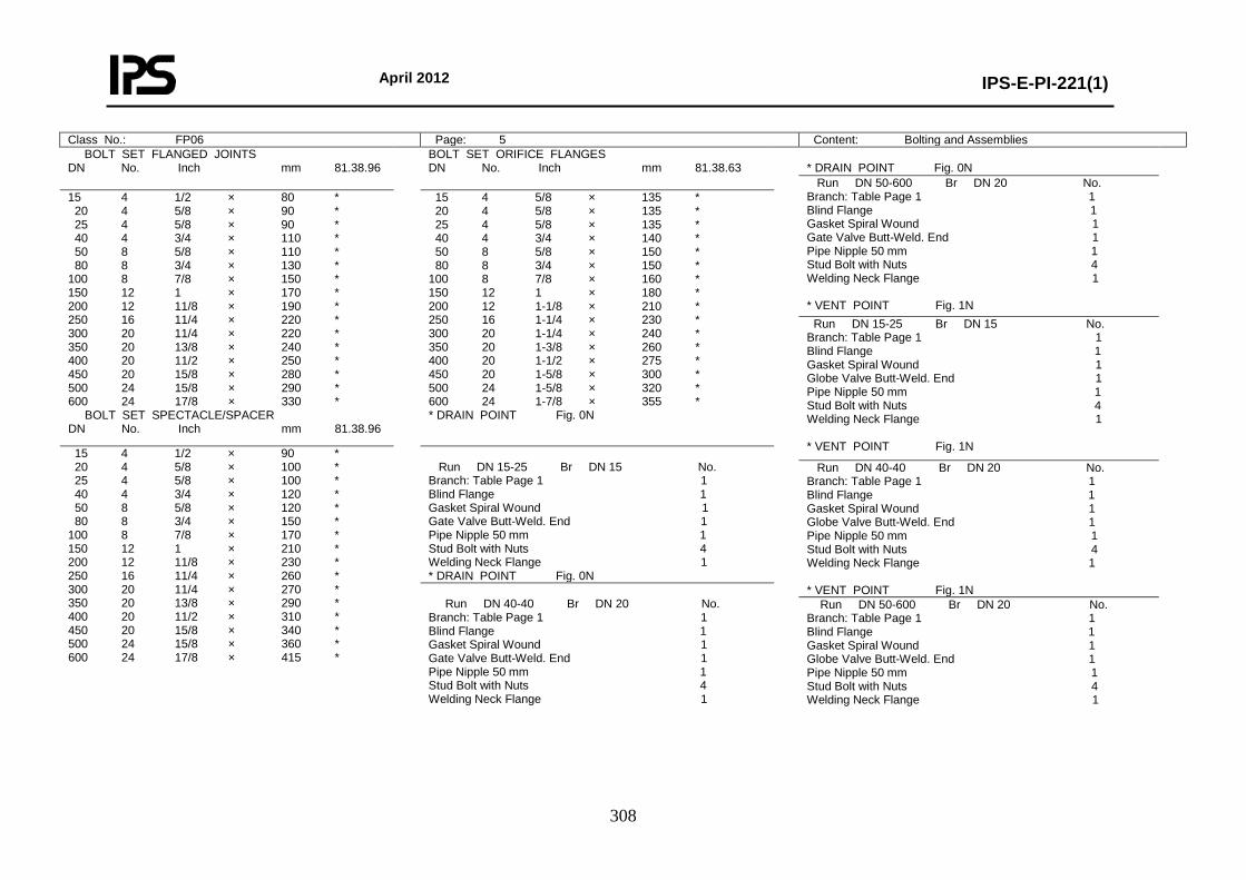
April 2012
IPS-E-PI-221(1)
308
Class No.: FP06 Page: 5 Content: Bolting and Assemblies BOLT SET FLANGED JOINTS DN No. Inch mm 81.38.96
BOLT SET ORIFICE FLANGES DN No. Inch mm 81.38.63
* DRAIN POINT Fig. 0N
Run DN 50-600 Br DN 20 No. Branch: Table Page 1 1 Blind Flange 1 Gasket Spiral Wound 1 Gate Valve Butt-Weld. End 1 Pipe Nipple 50 mm 1 Stud Bolt with Nuts 4 Welding Neck Flange 1 * VENT POINT Fig. 1N
15 4 1/2 × 80 * 20 4 5/8 × 90 * 25 4 5/8 × 90 * 40 4 3/4 × 110 * 50 8 5/8 × 110 * 80 8 3/4 × 130 * 100 8 7/8 × 150 * 150 12 1 × 170 * 200 12 11/8 × 190 * 250 16 11/4 × 220 * 300 20 11/4 × 220 * 350 20 13/8 × 240 * 400 20 11/2 × 250 * 450 20 15/8 × 280 * 500 24 15/8 × 290 * 600 24 17/8 × 330 * BOLT SET SPECTACLE/SPACER DN No. Inch mm 81.38.96
15 4 5/8 × 135 * 20 4 5/8 × 135 * 25 4 5/8 × 135 * 40 4 3/4 × 140 * 50 8 5/8 × 150 * 80 8 3/4 × 150 * 100 8 7/8 × 160 * 150 12 1 × 180 * 200 12 1-1/8 × 210 * 250 16 1-1/4 × 230 * 300 20 1-1/4 × 240 * 350 20 1-3/8 × 260 * 400 20 1-1/2 × 275 * 450 20 1-5/8 × 300 * 500 24 1-5/8 × 320 * 600 24 1-7/8 × 355 * * DRAIN POINT Fig. 0N
Run DN 15-25 Br DN 15 No. Branch: Table Page 1 1 Blind Flange 1 Gasket Spiral Wound 1 Globe Valve Butt-Weld. End 1 Pipe Nipple 50 mm 1 Stud Bolt with Nuts 4 Welding Neck Flange 1 * VENT POINT Fig. 1N 15 4 1/2 × 90 *
20 4 5/8 × 100 * 25 4 5/8 × 100 * 40 4 3/4 × 120 * 50 8 5/8 × 120 * 80 8 3/4 × 150 * 100 8 7/8 × 170 * 150 12 1 × 210 * 200 12 11/8 × 230 * 250 16 11/4 × 260 * 300 20 11/4 × 270 * 350 20 13/8 × 290 * 400 20 11/2 × 310 * 450 20 15/8 × 340 * 500 24 15/8 × 360 * 600 24 17/8 × 415 *
Run DN 15-25 Br DN 15 No. Branch: Table Page 1 1 Blind Flange 1 Gasket Spiral Wound 1 Gate Valve Butt-Weld. End 1 Pipe Nipple 50 mm 1 Stud Bolt with Nuts 4 Welding Neck Flange 1 * DRAIN POINT Fig. 0N
Run DN 40-40 Br DN 20 No. Branch: Table Page 1 1 Blind Flange 1 Gasket Spiral Wound 1 Globe Valve Butt-Weld. End 1 Pipe Nipple 50 mm 1 Stud Bolt with Nuts 4 Welding Neck Flange 1 * VENT POINT Fig. 1N
Run DN 40-40 Br DN 20 No. Branch: Table Page 1 1 Blind Flange 1 Gasket Spiral Wound 1 Gate Valve Butt-Weld. End 1 Pipe Nipple 50 mm 1 Stud Bolt with Nuts 4 Welding Neck Flange 1
Run DN 50-600 Br DN 20 No. Branch: Table Page 1 1 Blind Flange 1 Gasket Spiral Wound 1 Globe Valve Butt-Weld. End 1 Pipe Nipple 50 mm 1 Stud Bolt with Nuts 4 Welding Neck Flange 1
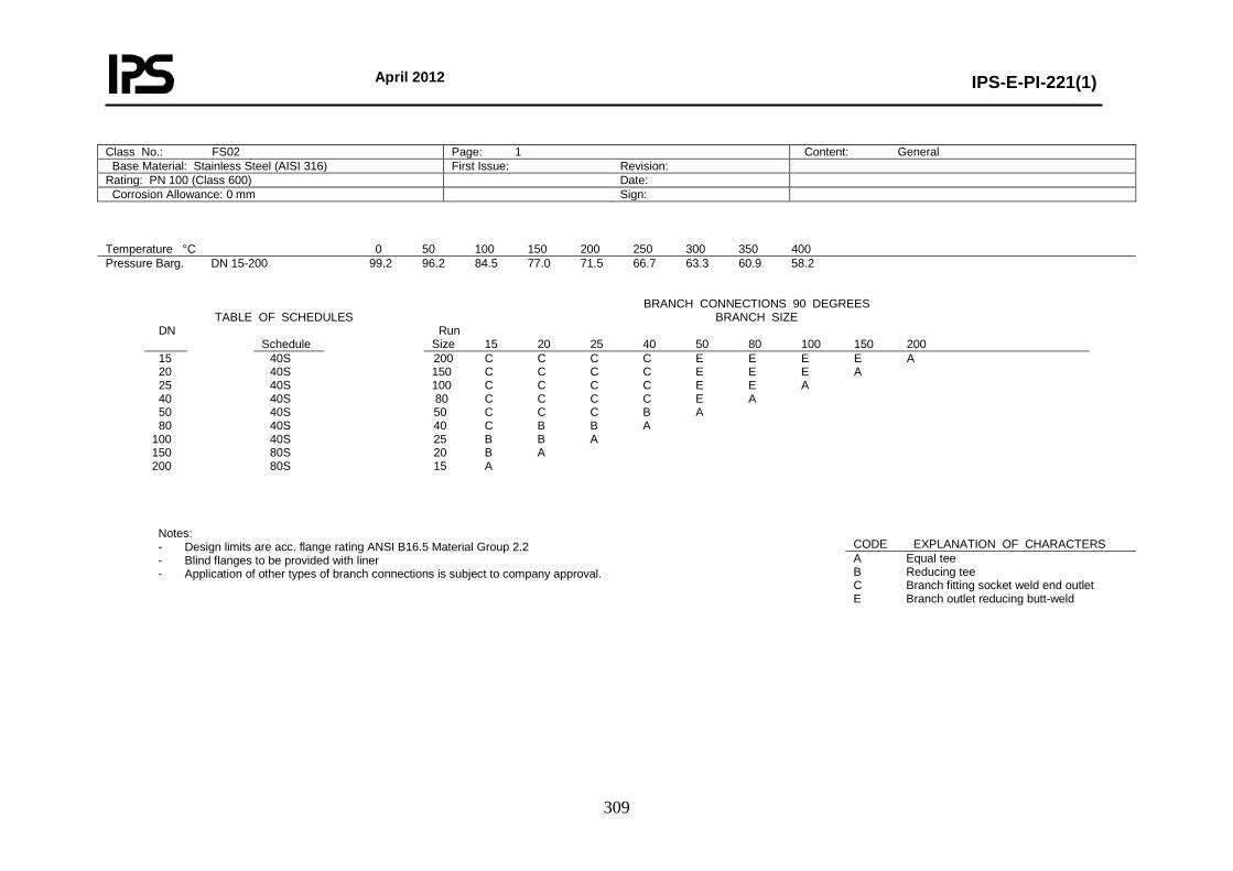
April 2012
IPS-E-PI-221(1)
309
Class No.: FS02 Page: 1 Content: General Base Material: Stainless Steel (AISI 316) First Issue: Revision: Rating: PN 100 (Class 600) Date: Corrosion Allowance: 0 mm Sign:
Temperature °C 0 50 100 150 200 250 300 350 400 Pressure Barg. DN 15-200 99.2 96.2 84.5 77.0 71.5 66.7 63.3 60.9 58.2
TABLE OF SCHEDULES
BRANCH CONNECTIONS 90 DEGREES BRANCH SIZE
DN Schedule
Run Size 15 20 25 40 50 80 100 150 200
15 20 25 40 50 80 100 150 200
40S 40S 40S 40S 40S 40S 40S 80S 80S
200 C C C C E E E E A 150 C C C C E E E A 100 C C C C E E A 80 C C C C E A 50 C C C B A 40 C B B A 25 B B A 20 B A 15 A
Notes: - Design limits are acc. flange rating ANSI B16.5 Material Group 2.2 - Blind flanges to be provided with liner - Application of other types of branch connections is subject to company approval.
CODE EXPLANATION OF CHARACTERS A Equal tee B Reducing tee C Branch fitting socket weld end outlet E Branch outlet reducing butt-weld
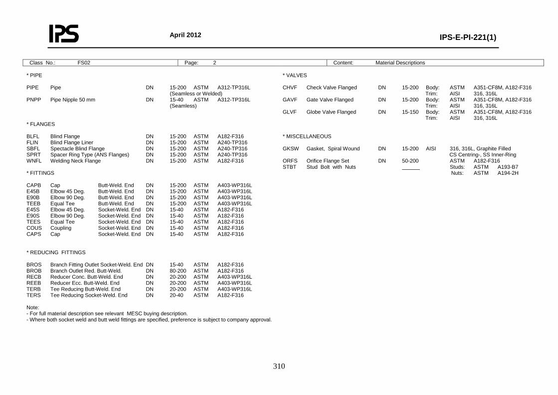
April 2012
IPS-E-PI-221(1)
310
Class No.: FS02 Page: 2 Content: Material Descriptions * PIPE PIPE Pipe DN 15-200 ASTM A312-TP316L (Seamless or Welded) PNPP Pipe Nipple 50 mm DN 15-40 ASTM A312-TP316L (Seamless) * FLANGES BLFL Blind Flange DN 15-200 ASTM A182-F316 FLIN Blind Flange Liner DN 15-200 ASTM A240-TP316 SBFL Spectacle Blind Flange DN 15-200 ASTM A240-TP316 SPRT Spacer Ring Type (ANS Flanges) DN 15-200 ASTM A240-TP316 WNFL Welding Neck Flange DN 15-200 ASTM A182-F316 * FITTINGS CAPB Cap Butt-Weld. End DN 15-200 ASTM A403-WP316L E45B Elbow 45 Deg. Butt-Weld. End DN 15-200 ASTM A403-WP316L E90B Elbow 90 Deg. Butt-Weld. End DN 15-200 ASTM A403-WP316L TEEB Equal Tee Butt-Weld. End DN 15-200 ASTM A403-WP316L E45S Elbow 45 Deg. Socket-Weld. End DN 15-40 ASTM A182-F316 E90S Elbow 90 Deg. Socket-Weld. End DN 15-40 ASTM A182-F316 TEES Equal Tee Socket-Weld. End DN 15-40 ASTM A182-F316 COUS Coupling Socket-Weld. End DN 15-40 ASTM A182-F316 CAPS Cap Socket-Weld. End DN 15-40 ASTM A182-F316 * REDUCING FITTINGS BROS Branch Fitting Outlet Socket-Weld. End DN 15-40 ASTM A182-F316 BROB Branch Outlet Red. Butt-Weld. DN 80-200 ASTM A182-F316 RECB Reducer Conc. Butt-Weld. End DN 20-200 ASTM A403-WP316L REEB Reducer Ecc. Butt-Weld. End DN 20-200 ASTM A403-WP316L TERB Tee Reducing Butt-Weld. End DN 20-200 ASTM A403-WP316L TERS Tee Reducing Socket-Weld. End DN 20-40 ASTM A182-F316 Note: - For full material description see relevant MESC buying description. - Where both socket weld and butt weld fittings are specified, preference is subject to company approval.
* VALVES CHVF Check Valve Flanged DN 15-200 Body: ASTM A351-CF8M, A182-F316 Trim: AISI 316, 316L GAVF Gate Valve Flanged DN 15-200 Body: ASTM A351-CF8M, A182-F316 Trim: AISI 316, 316L GLVF Globe Valve Flanged DN 15-150 Body: ASTM A351-CF8M, A182-F316 Trim: AISI 316, 316L * MISCELLANEOUS GKSW Gasket, Spiral Wound DN 15-200 AISI 316, 316L, Graphite Filled CS Centring-, SS Inner-Ring ORFS Orifice Flange Set DN 50-200 ASTM A182-F316 STBT Stud Bolt with Nuts ______ Studs: ASTM A193-B7 Nuts: ASTM A194-2H
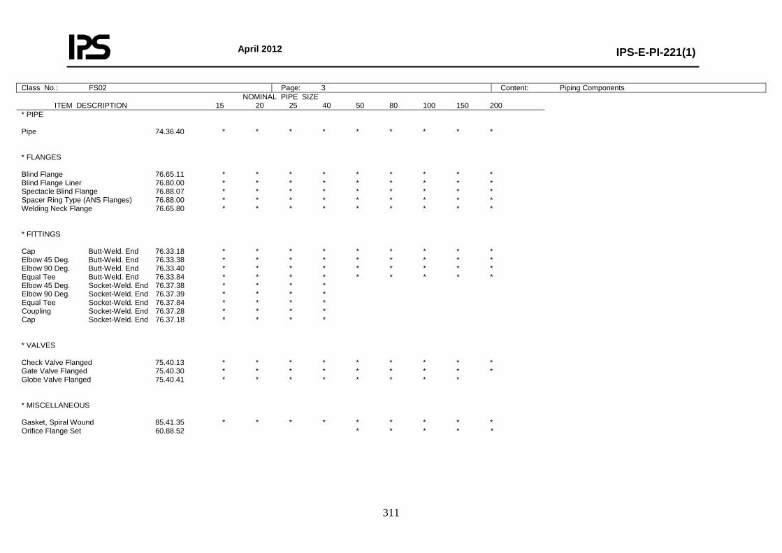
April 2012
IPS-E-PI-221(1)
311
Class No.: FS02 Page: 3 Content: Piping Components NOMINAL PIPE SIZE
ITEM DESCRIPTION 15 20 25 40 50 80 100 150 200
* PIPE Pipe 74.36.40 * * * * * * * * * * FLANGES Blind Flange 76.65.11 * * * * * * * * * Blind Flange Liner 76.80.00 * * * * * * * * * Spectacle Blind Flange 76.88.07 * * * * * * * * * Spacer Ring Type (ANS Flanges) 76.88.00 * * * * * * * * * Welding Neck Flange 76.65.80 * * * * * * * * * * FITTINGS Cap Butt-Weld. End 76.33.18 * * * * * * * * * Elbow 45 Deg. Butt-Weld. End 76.33.38 * * * * * * * * * Elbow 90 Deg. Butt-Weld. End 76.33.40 * * * * * * * * * Equal Tee Butt-Weld. End 76.33.84 * * * * * * * * * Elbow 45 Deg. Socket-Weld. End 76.37.38 * * * * Elbow 90 Deg. Socket-Weld. End 76.37.39 * * * * Equal Tee Socket-Weld. End 76.37.84 * * * * Coupling Socket-Weld. End 76.37.28 * * * * Cap Socket-Weld. End 76.37.18 * * * * * VALVES Check Valve Flanged 75.40.13 * * * * * * * * * Gate Valve Flanged 75.40.30 * * * * * * * * * Globe Valve Flanged 75.40.41 * * * * * * * * * MISCELLANEOUS Gasket, Spiral Wound 85.41.35 * * * * * * * * * Orifice Flange Set 60.88.52 * * * * *
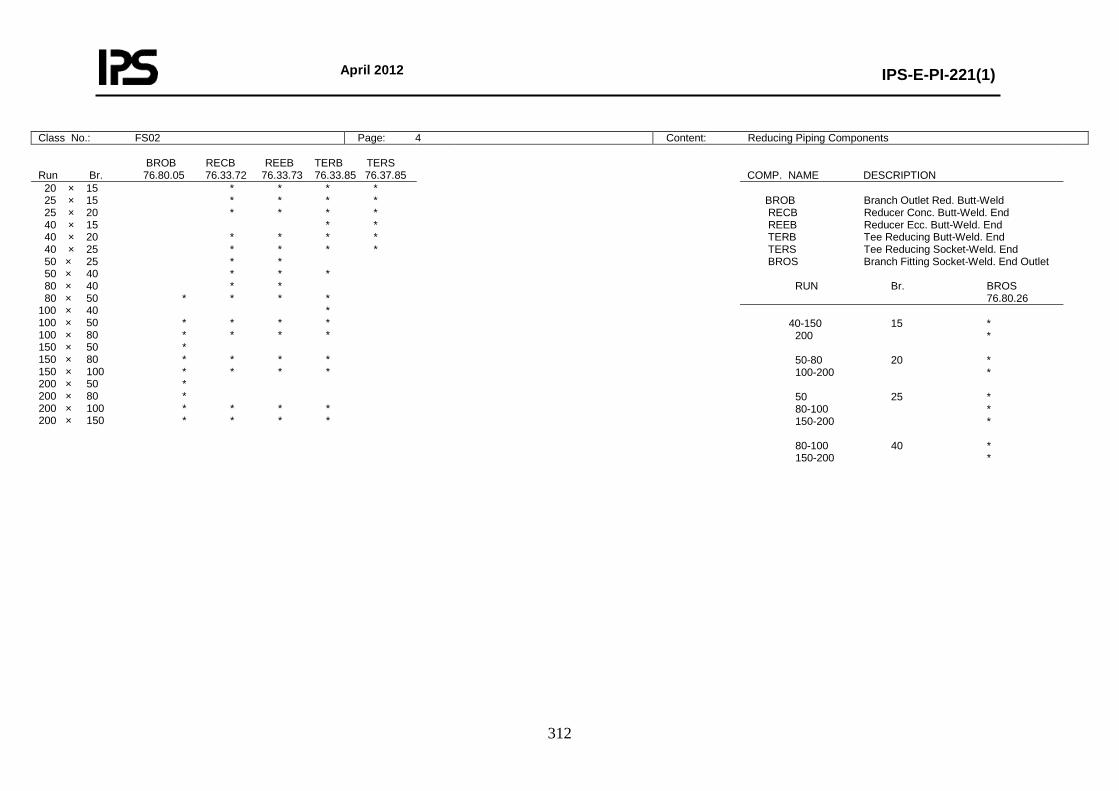
April 2012
IPS-E-PI-221(1)
312
Class No.: FS02 Page: 4 Content: Reducing Piping Components BROB RECB REEB TERB TERS Run Br. 76.80.05 76.33.72 76.33.73 76.33.85 76.37.85
COMP. NAME DESCRIPTION
20 × 15 * * * * 25 × 15 * * * * 25 × 20 * * * * 40 × 15 * * 40 × 20 * * * * 40 × 25 * * * * 50 × 25 * * 50 × 40 * * * 80 × 40 * * 80 × 50 * * * * 100 × 40 * 100 × 50 * * * * 100 × 80 * * * * 150 × 50 * 150 × 80 * * * * 150 × 100 * * * * 200 × 50 * 200 × 80 * 200 × 100 * * * * 200 × 150 * * * *
BROB Branch Outlet Red. Butt-Weld RECB Reducer Conc. Butt-Weld. End REEB Reducer Ecc. Butt-Weld. End TERB Tee Reducing Butt-Weld. End TERS Tee Reducing Socket-Weld. End BROS Branch Fitting Socket-Weld. End Outlet RUN Br. BROS 76.80.26
40-150 15 * 200 * 50-80 20 * 100-200 * 50 25 * 80-100 * 150-200 * 80-100 40 * 150-200 *
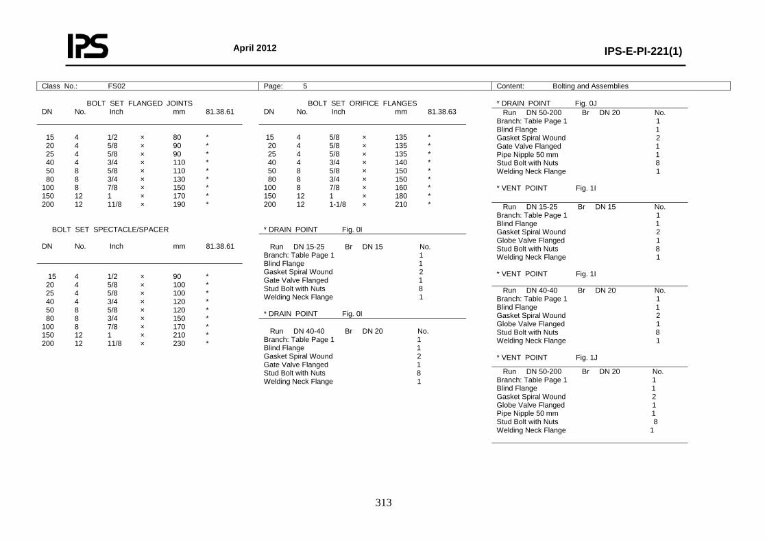
April 2012
IPS-E-PI-221(1)
313
Class No.: FS02 Page: 5 Content: Bolting and Assemblies
BOLT SET FLANGED JOINTS DN No. Inch mm 81.38.61
BOLT SET ORIFICE FLANGES
DN No. Inch mm 81.38.63
* DRAIN POINT Fig. 0J
Run DN 50-200 Br DN 20 No. Branch: Table Page 1 1 Blind Flange 1 Gasket Spiral Wound 2 Gate Valve Flanged 1 Pipe Nipple 50 mm 1 Stud Bolt with Nuts 8 Welding Neck Flange 1 * VENT POINT Fig. 1I
15 4 1/2 × 80 * 20 4 5/8 × 90 * 25 4 5/8 × 90 * 40 4 3/4 × 110 * 50 8 5/8 × 110 * 80 8 3/4 × 130 * 100 8 7/8 × 150 * 150 12 1 × 170 * 200 12 11/8 × 190 * BOLT SET SPECTACLE/SPACER DN No. Inch mm 81.38.61
15 4 5/8 × 135 * 20 4 5/8 × 135 * 25 4 5/8 × 135 * 40 4 3/4 × 140 * 50 8 5/8 × 150 * 80 8 3/4 × 150 * 100 8 7/8 × 160 * 150 12 1 × 180 * 200 12 1-1/8 × 210 * * DRAIN POINT Fig. 0I
Run DN 15-25 Br DN 15 No. Branch: Table Page 1 1 Blind Flange 1 Gasket Spiral Wound 2 Globe Valve Flanged 1 Stud Bolt with Nuts 8 Welding Neck Flange 1 * VENT POINT Fig. 1I
Run DN 15-25 Br DN 15 No. Branch: Table Page 1 1 Blind Flange 1 Gasket Spiral Wound 2 Gate Valve Flanged 1 Stud Bolt with Nuts 8 Welding Neck Flange 1 * DRAIN POINT Fig. 0I
15 4 1/2 × 90 * 20 4 5/8 × 100 * 25 4 5/8 × 100 * 40 4 3/4 × 120 * 50 8 5/8 × 120 * 80 8 3/4 × 150 * 100 8 7/8 × 170 * 150 12 1 × 210 * 200 12 11/8 × 230 *
Run DN 40-40 Br DN 20 No. Branch: Table Page 1 1 Blind Flange 1 Gasket Spiral Wound 2 Globe Valve Flanged 1 Stud Bolt with Nuts 8 Welding Neck Flange 1 * VENT POINT Fig. 1J
Run DN 40-40 Br DN 20 No. Branch: Table Page 1 1 Blind Flange 1 Gasket Spiral Wound 2 Gate Valve Flanged 1 Stud Bolt with Nuts 8 Welding Neck Flange 1
Run DN 50-200 Br DN 20 No. Branch: Table Page 1 1 Blind Flange 1 Gasket Spiral Wound 2 Globe Valve Flanged 1 Pipe Nipple 50 mm 1 Stud Bolt with Nuts 8 Welding Neck Flange 1
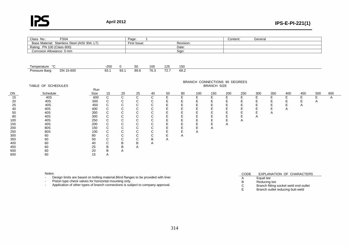
April 2012
IPS-E-PI-221(1)
314
Class No.: FS04 Page: 1 Content: General Base Material: Stainless Steel (AISI 304, LT) First Issue: Revision: Rating: PN 100 (Class 600) Date: Corrosion Allowance: 0 mm Sign:
Temperature °C -200 0 50 100 125 150 Pressure Barg. DN 15-600 93.1 93.1 89.6 76.3 72.7 69.2
TABLE OF SCHEDULES
BRANCH CONNECTIONS 90 DEGREES BRANCH SIZE
DN
Schedule
Run Size 15 20 25 40 50 80 100 150 200 250 300 350 400 450 500 600
15 20 25 40 50 80 100 150 200 250 300 350 400 450 500 600
40S 40S 40S 40S 40S 40S 40S 40S 80S 80S 60 60 60 60 60 60
600 C C C C E E E E E E E E E E E A 500 C C C C E E E E E E E E E E A 450 C C C C E E E E E E E E E A 400 C C C C E E E E E E E E A 350 C C C C E E E E E E E A 300 C C C C E E E E E E A 250 C C C C E E E E E A 200 C C C C E E E E A 150 C C C C E E E A 100 C C C C E E A 80 C C C C E A 50 C C C B A 40 C B B A 25 B B A 20 B A 15 A
Notes: - Design limits are based on bolting material.Blind flanges to be provided with liner - Piston type check valves for horizontal mounting only. - Application of other types of branch connections is subject to company approval.
CODE EXPLANATION OF CHARACTERS A Equal tee B Reducing tee C Branch fitting socket weld end outlet E Branch outlet reducing butt-weld
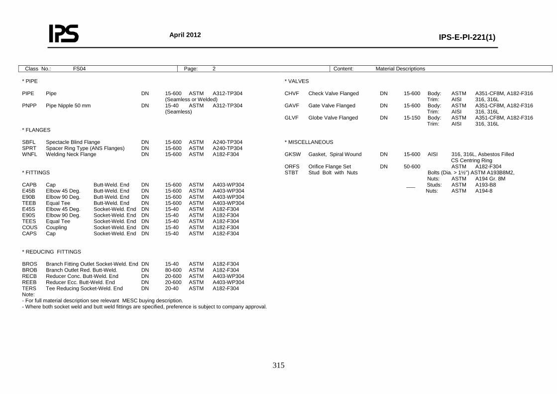
April 2012
IPS-E-PI-221(1)
315
Class No.: FS04 Page: 2 Content: Material Descriptions * PIPE PIPE Pipe DN 15-600 ASTM A312-TP304 (Seamless or Welded) PNPP Pipe Nipple 50 mm DN 15-40 ASTM A312-TP304 (Seamless) * FLANGES SBFL Spectacle Blind Flange DN 15-600 ASTM A240-TP304 SPRT Spacer Ring Type (ANS Flanges) DN 15-600 ASTM A240-TP304 WNFL Welding Neck Flange DN 15-600 ASTM A182-F304 * FITTINGS CAPB Cap Butt-Weld. End DN 15-600 ASTM A403-WP304 E45B Elbow 45 Deg. Butt-Weld. End DN 15-600 ASTM A403-WP304 E90B Elbow 90 Deg. Butt-Weld. End DN 15-600 ASTM A403-WP304 TEEB Equal Tee Butt-Weld. End DN 15-600 ASTM A403-WP304 E45S Elbow 45 Deg. Socket-Weld. End DN 15-40 ASTM A182-F304 E90S Elbow 90 Deg. Socket-Weld. End DN 15-40 ASTM A182-F304 TEES Equal Tee Socket-Weld. End DN 15-40 ASTM A182-F304 COUS Coupling Socket-Weld. End DN 15-40 ASTM A182-F304 CAPS Cap Socket-Weld. End DN 15-40 ASTM A182-F304 * REDUCING FITTINGS BROS Branch Fitting Outlet Socket-Weld. End DN 15-40 ASTM A182-F304 BROB Branch Outlet Red. Butt-Weld. DN 80-600 ASTM A182-F304 RECB Reducer Conc. Butt-Weld. End DN 20-600 ASTM A403-WP304 REEB Reducer Ecc. Butt-Weld. End DN 20-600 ASTM A403-WP304 TERS Tee Reducing Socket-Weld. End DN 20-40 ASTM A182-F304 Note: - For full material description see relevant MESC buying description. - Where both socket weld and butt weld fittings are specified, preference is subject to company approval.
* VALVES CHVF Check Valve Flanged DN 15-600 Body: ASTM A351-CF8M, A182-F316 Trim: AISI 316, 316L GAVF Gate Valve Flanged DN 15-600 Body: ASTM A351-CF8M, A182-F316 Trim: AISI 316, 316L GLVF Globe Valve Flanged DN 15-150 Body: ASTM A351-CF8M, A182-F316 Trim: AISI 316, 316L * MISCELLANEOUS GKSW Gasket, Spiral Wound DN 15-600 AISI 316, 316L, Asbestos Filled CS Centring Ring ORFS Orifice Flange Set DN 50-600 ASTM A182-F304 STBT Stud Bolt with Nuts Bolts (Dia. > 1½") ASTM A193B8M2, Nuts: ASTM A194 Gr. 8M ___ Studs: ASTM A193-B8 Nuts: ASTM A194-8
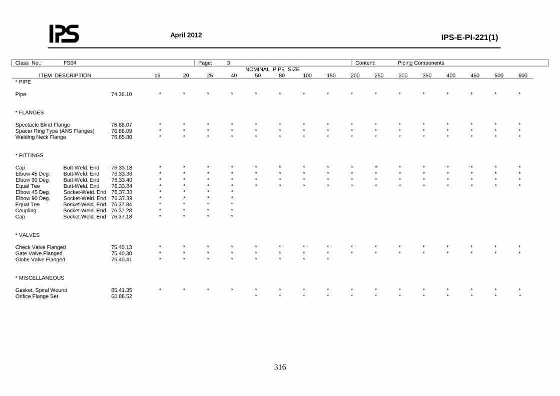
April 2012
IPS-E-PI-221(1)
316
Class No.: FS04 Page: 3 Content: Piping Components NOMINAL PIPE SIZE
ITEM DESCRIPTION 15 20 25 40 50 80 100 150 200 250 300 350 400 450 500 600
* PIPE Pipe 74.36.10 * * * * * * * * * * * * * * * * * FLANGES Spectacle Blind Flange 76.88.07 * * * * * * * * * * * * * * * * Spacer Ring Type (ANS Flanges) 76.88.09 * * * * * * * * * * * * * * * * Welding Neck Flange 76.65.80 * * * * * * * * * * * * * * * * * FITTINGS Cap Butt-Weld. End 76.33.18 * * * * * * * * * * * * * * * * Elbow 45 Deg. Butt-Weld. End 76.33.38 * * * * * * * * * * * * * * * * Elbow 90 Deg. Butt-Weld. End 76.33.40 * * * * * * * * * * * * * * * * Equal Tee Butt-Weld. End 76.33.84 * * * * * * * * * * * * * * * * Elbow 45 Deg. Socket-Weld. End 76.37.38 * * * * Elbow 90 Deg. Socket-Weld. End 76.37.39 * * * * Equal Tee Socket-Weld. End 76.37.84 * * * * Coupling Socket-Weld. End 76.37.28 * * * * Cap Socket-Weld. End 76.37.18 * * * * * VALVES Check Valve Flanged 75.40.13 * * * * * * * * * * * * * * * * Gate Valve Flanged 75.40.30 * * * * * * * * * * * * * * * * Globe Valve Flanged 75.40.41 * * * * * * * * * MISCELLANEOUS Gasket, Spiral Wound 85.41.35 * * * * * * * * * * * * * * * * Orifice Flange Set 60.88.52 * * * * * * * * * * * *
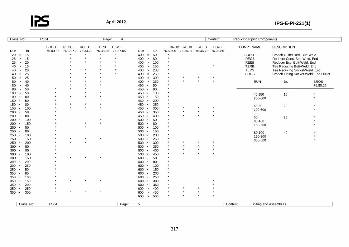
April 2012
IPS-E-PI-221(1)
317
Class No.: FS04 Page: 4 Content: Reducing Piping Components BROB RECB REEB TERB TERS Run Br. 76.80.05 76.33.71 76.33.73 76.33.85 76.37.85
BROB RECB REEB TERB Run Br. 76.80.05 76.36.71 76.36.73 76.33.85
COMP. NAME DESCRIPTION
20 × 15 * * * * 25 × 15 * * * * 25 × 20 * * * * 40 × 15 * * * 40 × 20 * * * * 40 × 25 * * * * 50 × 25 * * * 50 × 40 * * * 80 × 40 * * * 80 × 50 * * * 100 × 50 * * * 100 × 80 * * * * 150 × 50 * 150 × 80 * * * * 150 × 100 * * * * 200 × 50 * 200 × 80 * 200 × 100 * * 200 × 150 * * * 250 × 50 * * 250 × 80 * 250 × 100 * 250 × 150 * * * * 250 × 200 * * * 300 × 50 * 300 × 80 * 300 × 100 * 300 × 150 * * * * 300 × 200 * 300 × 250 * 350 × 50 * 350 × 80 * 350 × 100 * 350 × 150 * * * * 350 × 200 * 350 × 250 * 350 × 300 * * * *
400 × 50 * 400 × 80 * 400 × 100 * 400 × 150 * * 400 × 200 * 400 × 250 * 400 × 300 * * * * 400 × 350 * * * * 450 × 50 * 450 × 80 * 450 × 100 * 450 × 150 * 450 × 200 * 450 × 250 * 450 × 300 * * * * 450 × 350 * * * * 450 × 400 * * * * 500 × 50 * 500 × 80 * 500 × 100 * 500 × 150 * 500 × 200 * 500 × 250 * 500 × 300 * * * * 500 × 350 * * * * 500 × 400 * * * * 500 × 450 * * * * 600 × 50 * 600 × 80 * 600 × 100 * 600 × 150 * 600 × 200 * 600 × 250 * 600 × 300 * * 600 × 350 * * 600 × 400 * * * * 600 × 450 * * * * 600 × 500 * * * *
BROB Branch Outlet Red. Butt-Weld RECB Reducer Conc. Butt-Weld. End REEB Reducer Ecc. Butt-Weld. End TERB Tee Reducing Butt-Weld. End TERS Tee Reducing Socket-Weld. End BROS Branch Fitting Socket-Weld. End Outlet RUN Br. BROS 76.80.26
40-150 15 * 200-600 * 50-80 20 * 100-600 * 50 25 * 80-100 * 150-600 * 80-100 40 * 150-300 * 350-600 *
Class No.: FS04 Page: 5 Content: Bolting and Assemblies
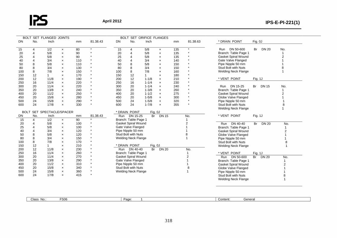
April 2012
IPS-E-PI-221(1)
318
BOLT SET FLANGED JOINTS DN No. Inch mm 81.38.43
BOLT SET ORIFICE FLANGES DN No. Inch mm 81.38.63
* DRAIN POINT Fig. 0J
Run DN 50-600 Br DN 20 No. Branch: Table Page 1 1 Gasket Spiral Wound 2 Gate Valve Flanged 1 Pipe Nipple 50 mm 1 Stud Bolt with Nuts 8 Welding Neck Flange 1 * VENT POINT Fig. 1J
15 4 1/2 × 80 * 20 4 5/8 × 90 * 25 4 5/8 × 90 * 40 4 3/4 × 110 * 50 8 5/8 × 110 * 80 8 3/4 × 130 * 100 8 7/8 × 150 * 150 12 1 × 170 * 200 12 11/8 × 190 * 250 16 11/4 × 220 * 300 20 11/4 × 220 * 350 20 13/8 × 240 * 400 20 11/2 × 250 * 450 20 15/8 × 280 * 500 24 15/8 × 290 * 600 24 17/8 × 330 * BOLT SET SPECTACLE/SPACER DN No. Inch mm 81.38.43
15 4 5/8 × 135 * 20 4 5/8 × 135 * 25 4 5/8 × 135 * 40 4 3/4 × 140 * 50 8 5/8 × 150 * 80 8 3/4 × 150 * 100 8 7/8 × 160 * 150 12 1 × 180 * 200 12 1-1/8 × 210 * 250 16 1-1/4 × 230 * 300 20 1-1/4 × 240 * 350 20 1-3/8 × 260 * 400 20 1-1/2 × 275 * 450 20 1-5/8 × 300 * 500 24 1-5/8 × 320 * 600 24 1-7/8 × 355 * * DRAIN POINT Fig. 0J
Run DN 15-25 Br DN 15 No. Branch: Table Page 1 1 Gasket Spiral Wound 2 Globe Valve Flanged 1 Pipe Nipple 50 mm 1 Stud Bolt with Nuts 8 Welding Neck Flange 1 * VENT POINT Fig. 1J Run DN 15-25 Br DN 15 No.
Branch: Table Page 1 1 Gasket Spiral Wound 2 Gate Valve Flanged 1 Pipe Nipple 50 mm 1 Stud Bolt with Nuts 8 Welding Neck Flange 1 * DRAIN POINT Fig. 0J
15 4 1/2 × 90 * 20 4 5/8 × 100 * 25 4 5/8 × 100 * 40 4 3/4 × 120 * 50 8 5/8 × 120 * 80 8 3/4 × 150 * 100 8 7/8 × 170 * 150 12 1 × 210 * 200 12 11/8 × 230 * 250 16 11/4 × 260 * 300 20 11/4 × 270 * 350 20 13/8 × 290 * 400 20 11/2 × 310 * 450 20 15/8 × 340 * 500 24 15/8 × 360 * 600 24 17/8 × 415 *
Run DN 40-40 Br DN 20 No. Branch: Table Page 1 1 Gasket Spiral Wound 2 Globe Valve Flanged 1 Pipe Nipple 50 mm 1 Stud Bolt with Nuts 8 Welding Neck Flange 1 * VENT POINT Fig. 1J
Run DN 40-40 Br DN 20 No. Branch: Table Page 1 1 Gasket Spiral Wound 2 Gate Valve Flanged 1 Pipe Nipple 50 mm 1 Stud Bolt with Nuts 8 Welding Neck Flange 1
Run DN 50-600 Br DN 20 No. Branch: Table Page 1 1 Gasket Spiral Wound 2 Globe Valve Flanged 1 Pipe Nipple 50 mm 1 Stud Bolt with Nuts 8 Welding Neck Flange 1
Class No.: FS06 Page: 1 Content: General
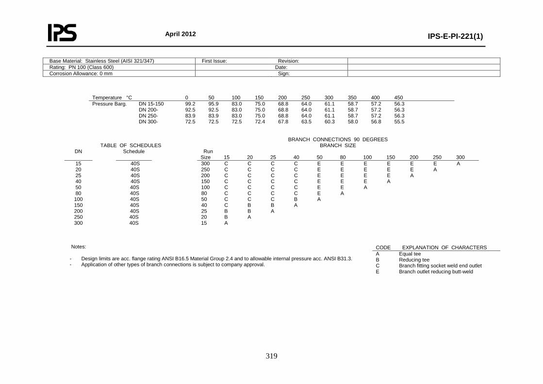
April 2012
IPS-E-PI-221(1)
319
Base Material: Stainless Steel (AISI 321/347) First Issue: Revision: Rating: PN 100 (Class 600) Date: Corrosion Allowance: 0 mm Sign:
Temperature °C 0 50 100 150 200 250 300 350 400 450 Pressure Barg. DN 15-150 99.2 95.9 83.0 75.0 68.8 64.0 61.1 58.7 57.2 56.3 DN 200- 92.5 92.5 83.0 75.0 68.8 64.0 61.1 58.7 57.2 56.3 DN 250- 83.9 83.9 83.0 75.0 68.8 64.0 61.1 58.7 57.2 56.3 DN 300- 72.5 72.5 72.5 72.4 67.8 63.5 60.3 58.0 56.8 55.5
TABLE OF SCHEDULES
BRANCH CONNECTIONS 90 DEGREES BRANCH SIZE
DN Schedule Run Size 15 20 25 40 50 80 100 150 200 250 300
15 20 25 40 50 80 100 150 200 250 300
40S 40S 40S 40S 40S 40S 40S 40S 40S 40S 40S
300 C C C C E E E E E E A 250 C C C C E E E E E A 200 C C C C E E E E A 150 C C C C E E E A 100 C C C C E E A 80 C C C C E A 50 C C C B A 40 C B B A 25 B B A 20 B A 15 A
Notes:
- Design limits are acc. flange rating ANSI B16.5 Material Group 2.4 and to allowable internal pressure acc. ANSI B31.3. - Application of other types of branch connections is subject to company approval.
CODE EXPLANATION OF CHARACTERS A Equal tee B Reducing tee C Branch fitting socket weld end outlet E Branch outlet reducing butt-weld
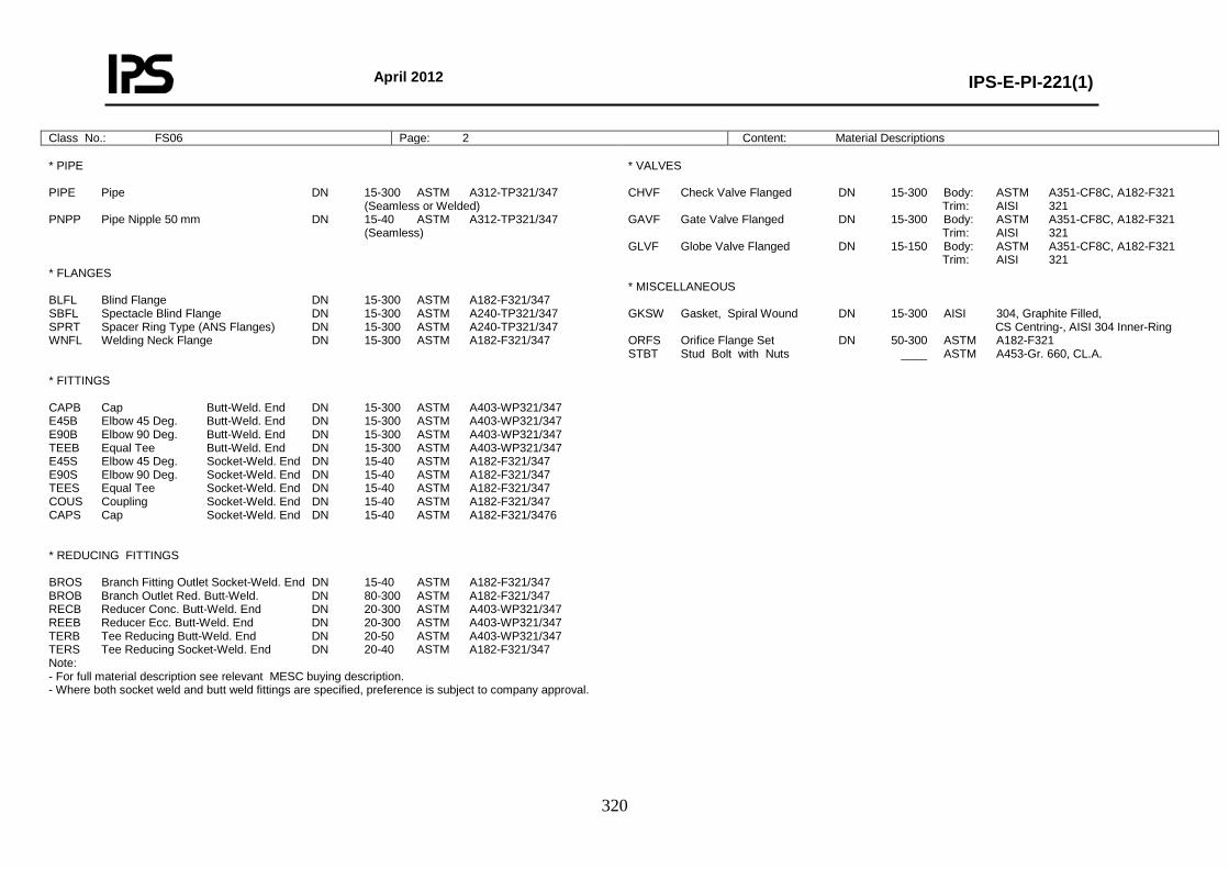
April 2012
IPS-E-PI-221(1)
320
Class No.: FS06 Page: 2 Content: Material Descriptions * PIPE PIPE Pipe DN 15-300 ASTM A312-TP321/347 (Seamless or Welded) PNPP Pipe Nipple 50 mm DN 15-40 ASTM A312-TP321/347 (Seamless) * FLANGES BLFL Blind Flange DN 15-300 ASTM A182-F321/347 SBFL Spectacle Blind Flange DN 15-300 ASTM A240-TP321/347 SPRT Spacer Ring Type (ANS Flanges) DN 15-300 ASTM A240-TP321/347 WNFL Welding Neck Flange DN 15-300 ASTM A182-F321/347 * FITTINGS CAPB Cap Butt-Weld. End DN 15-300 ASTM A403-WP321/347 E45B Elbow 45 Deg. Butt-Weld. End DN 15-300 ASTM A403-WP321/347 E90B Elbow 90 Deg. Butt-Weld. End DN 15-300 ASTM A403-WP321/347 TEEB Equal Tee Butt-Weld. End DN 15-300 ASTM A403-WP321/347 E45S Elbow 45 Deg. Socket-Weld. End DN 15-40 ASTM A182-F321/347 E90S Elbow 90 Deg. Socket-Weld. End DN 15-40 ASTM A182-F321/347 TEES Equal Tee Socket-Weld. End DN 15-40 ASTM A182-F321/347 COUS Coupling Socket-Weld. End DN 15-40 ASTM A182-F321/347 CAPS Cap Socket-Weld. End DN 15-40 ASTM A182-F321/3476 * REDUCING FITTINGS BROS Branch Fitting Outlet Socket-Weld. End DN 15-40 ASTM A182-F321/347 BROB Branch Outlet Red. Butt-Weld. DN 80-300 ASTM A182-F321/347 RECB Reducer Conc. Butt-Weld. End DN 20-300 ASTM A403-WP321/347 REEB Reducer Ecc. Butt-Weld. End DN 20-300 ASTM A403-WP321/347 TERB Tee Reducing Butt-Weld. End DN 20-50 ASTM A403-WP321/347 TERS Tee Reducing Socket-Weld. End DN 20-40 ASTM A182-F321/347 Note: - For full material description see relevant MESC buying description. - Where both socket weld and butt weld fittings are specified, preference is subject to company approval.
* VALVES CHVF Check Valve Flanged DN 15-300 Body: ASTM A351-CF8C, A182-F321 Trim: AISI 321 GAVF Gate Valve Flanged DN 15-300 Body: ASTM A351-CF8C, A182-F321 Trim: AISI 321 GLVF Globe Valve Flanged DN 15-150 Body: ASTM A351-CF8C, A182-F321 Trim: AISI 321 * MISCELLANEOUS GKSW Gasket, Spiral Wound DN 15-300 AISI 304, Graphite Filled, CS Centring-, AISI 304 Inner-Ring ORFS Orifice Flange Set DN 50-300 ASTM A182-F321 STBT Stud Bolt with Nuts ____ ASTM A453-Gr. 660, CL.A.

April 2012
IPS-E-PI-221(1)
321
Class No.: FS06 Page: 3 Content: Piping Components NOMINAL PIPE SIZE
ITEM DESCRIPTION 15 20 25 40 50 80 100 150 200 250 300
* PIPE Pipe 74.36.60 * * * * * * * * * * * 76.36.40 * FLANGES Blind Flange 76.65.10 * * * * * * * * * * * Spectacle Blind Flange 76.88.07 * * * * * * * * * * * Spacer Ring Type (ANS Flanges) 76.88.00 * * * * * * * * * * * Welding Neck Flange 76.65.80 * * * * * * * * * * * * FITTINGS Cap Butt-Weld. End 76.33.18 * * * * * * * * * * * Elbow 45 Deg. Butt-Weld. End 76.33.38 * * * * * * * * * * * Elbow 90 Deg. Butt-Weld. End 76.33.39 * * * * * * * * * * * Equal Tee Butt-Weld. End 76.33.84 * * * * * * * * * * * Elbow 45 Deg. Socket-Weld. End 76.37.38 * * * * Elbow 90 Deg. Socket-Weld. End 76.37.39 * * * * Equal Tee Socket-Weld. End 76.37.84 * * * * Coupling Socket-Weld. End 76.37.28 * * * * Cap Socket-Weld. End 76.37.18 * * * * * VALVES Check Valve Flanged 75.40.13 * * * * * * * * * * * Gate Valve Flanged 75.40.30 * * * * * * * * * * * Globe Valve Flanged 75.40.40 * * * * * * * * * MISCELLANEOUS Gasket, Spiral Wound 85.41.31 * * * * * * * * * * * Orifice Flange Set 60.88.52 * * * * * * *
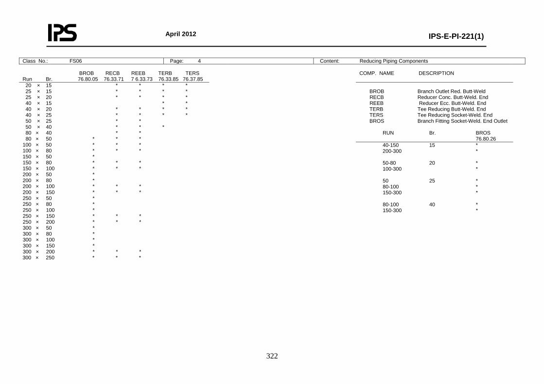
April 2012
IPS-E-PI-221(1)
322
Class No.: FS06 Page: 4 Content: Reducing Piping Components BROB RECB REEB TERB TERS Run Br. 76.80.05 76.33.71 7 6.33.73 76.33.85 76.37.85
COMP. NAME DESCRIPTION
20 × 15 * * * * 25 × 15 * * * * 25 × 20 * * * * 40 × 15 * * 40 × 20 * * * * 40 × 25 * * * * 50 × 25 * * 50 × 40 * * * 80 × 40 * * 80 × 50 * * * 100 × 50 * * * 100 × 80 * * * 150 × 50 * 150 × 80 * * * 150 × 100 * * * 200 × 50 * 200 × 80 * 200 × 100 * * * 200 × 150 * * * 250 × 50 * 250 × 80 * 250 × 100 * 250 × 150 * * * 250 × 200 * * * 300 × 50 * 300 × 80 * 300 × 100 * 300 × 150 * 300 × 200 * * * 300 × 250 * * *
BROB Branch Outlet Red. Butt-Weld RECB Reducer Conc. Butt-Weld. End REEB Reducer Ecc. Butt-Weld. End TERB Tee Reducing Butt-Weld. End TERS Tee Reducing Socket-Weld. End BROS Branch Fitting Socket-Weld. End Outlet RUN Br. BROS 76.80.26
40-150 15 * 200-300 * 50-80 20 * 100-300 * 50 25 * 80-100 * 150-300 * 80-100 40 * 150-300 *
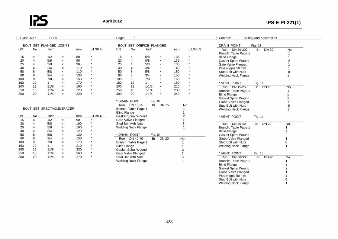
April 2012
IPS-E-PI-221(1)
323
Class No.: FS06 Page: 5 Content: Bolting and Assemblies BOLT SET FLANGED JOINTS DN No. Inch mm 81.38.40
BOLT SET ORIFICE FLANGES DN No. Inch mm 81.38.63
DRAIN POINT Fig. 0J
Run DN 50-300 Br DN 20 No. Branch: Table Page 1 1 Blind Flange 1 Gasket Spiral Wound 2 Gate Valve Flanged 1 Pipe Nipple 50 mm 1 Stud Bolt with Nuts 8 Welding Neck Flange 1 * VENT POINT Fig. 1I
15 4 1/2 × 80 * 20 4 5/8 × 90 * 25 4 5/8 × 90 * 40 4 3/4 × 110 * 50 8 5/8 × 110 * 80 8 3/4 × 130 * 100 8 7/8 × 150 * 150 12 1 × 170 * 200 12 11/8 × 190 * 250 16 11/4 × 220 * 300 20 11/4 × 220 * BOLT SET SPECTACLE/SPACER DN No. Inch mm 81.38.40
15 4 5/8 × 135 * 20 4 5/8 × 135 * 25 4 5/8 × 135 * 40 4 3/4 × 140 * 50 8 5/8 × 150 * 80 8 3/4 × 150 * 100 8 7/8 × 160 * 150 12 1 × 180 * 200 12 1-1/8 × 210 * 250 16 1-1/4 × 230 * 300 20 1-1/4 × 240 * * DRAIN POINT Fig. 0I
Run DN 15-25 Br DN 15 No. Branch: Table Page 1 1 Blind Flange 1 Gasket Spiral Wound 2 Globe Valve Flanged 1 Stud Bolt with Nuts 8 Welding Neck Flange 1 * VENT POINT Fig. 1I
Run DN 15-25 Br DN 15 No. Branch: Table Page 1 1 Blind Flange 1 Gasket Spiral Wound 2 Gate Valve Flanged 1 Stud Bolt with Nuts 8 Welding Neck Flange 1 * DRAIN POINT Fig. 0I
15 4 1/2 × 90 * 20 4 5/8 × 100 * 25 4 5/8 × 100 * 40 4 3/4 × 120 * 50 8 5/8 × 120 * 80 8 3/4 × 150 * 100 8 7/8 × 170 * 150 12 1 × 210 * 200 12 11/8 × 230 * 250 16 11/4 × 260 * 300 20 11/4 × 270 *
Run DN 40-40 Br DN 20 No. Branch: Table Page 1 1 Blind Flange 1 Gasket Spiral Wound 2 Globe Valve Flanged 1 Stud Bolt with Nuts 8 Welding Neck Flange 1 * VENT POINT Fig. 1J
Run DN 40-40 Br DN 20 No. Branch: Table Page 1 1 Blind Flange 1 Gasket Spiral Wound 2 Gate Valve Flanged 1 Stud Bolt with Nuts 8 Welding Neck Flange 1
Run DN 50-300 Br DN 20 No. Branch: Table Page 1 1 Blind Flange 1 Gasket Spiral Wound 2 Globe Valve Flanged 1 Pipe Nipple 50 mm 1 Stud Bolt with Nuts 8 Welding Neck Flange 1
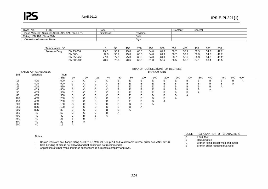
April 2012
IPS-E-PI-221(1)
324
Class No.: FS07 Page: 1 Content: General Base Material: Stainless Steel (AISI 321, Stab. HT) First Issue: Revision: Rating: PN 100 (Class 600) Date: Corrosion Allowance: 0 mm Sign:
Temperature °C 0 50 150 200 250 300 350 400 450 500 538 Pressure Barg. DN 15-250 99.2 95.9 75.0 68.8 64.0 61.1 58.7 57.2 56.3 54.3 49.2 DN 300- 97.3 95.9 75.0 68.8 64.0 61.1 58.7 57.2 56.3 54.3 49.2 DN 350-450 77.0 77.0 75.0 68.8 64.0 61.1 58.7 57.2 56.3 54.3 49.2 DN 500-600 70.6 70.6 70.6 66.0 61.8 58.7 56.5 55.3 54.1 53.4 48.5
TABLE OF SCHEDULES BRANCH CONNECTIONS 90 DEGREES
BRANCH SIZE DN Schedule Run
Size 15 20 25 40 50 80 100 150 200 250 300 350 400 450 500 600 15 20 25 40 50 80
100 150 200 250 300 350 400 450 500 600
40S 40S 40S 40S 40S 40S 40S 40S 80S 80S 80S 40 40 40 40 40
600 C C C C E E E E E E B B B B B A 500 C C C C E E E E E B B B B B A 450 C C C C E E E E E B B B B A 400 C C C C E E E E B B B B A 350 C C C C E E E E B B B A 300 C C C C E E E B B B A 250 C C C C E E E B B A 200 C C C C E E B B A 150 C C C C E B B A 100 C C C C B B A 80 C C C B B A 50 C C C B A 40 C B B A 25 B B A 20 B A 15 A
Notes:
- Design limits are acc. flange rating ANSI B16.5 Material Group 2.4 and to allowable internal prisor acc. ANSI B31.3. - Cold bending of pipe is not allowed and hot bending is not recommended. - Application of other types of branch connections is subject to company approval.
CODE EXPLANATION OF CHARACTERS A Equal tee B Reducing tee C Branch fitting socket weld end outlet E Branch outlet reducing butt-weld
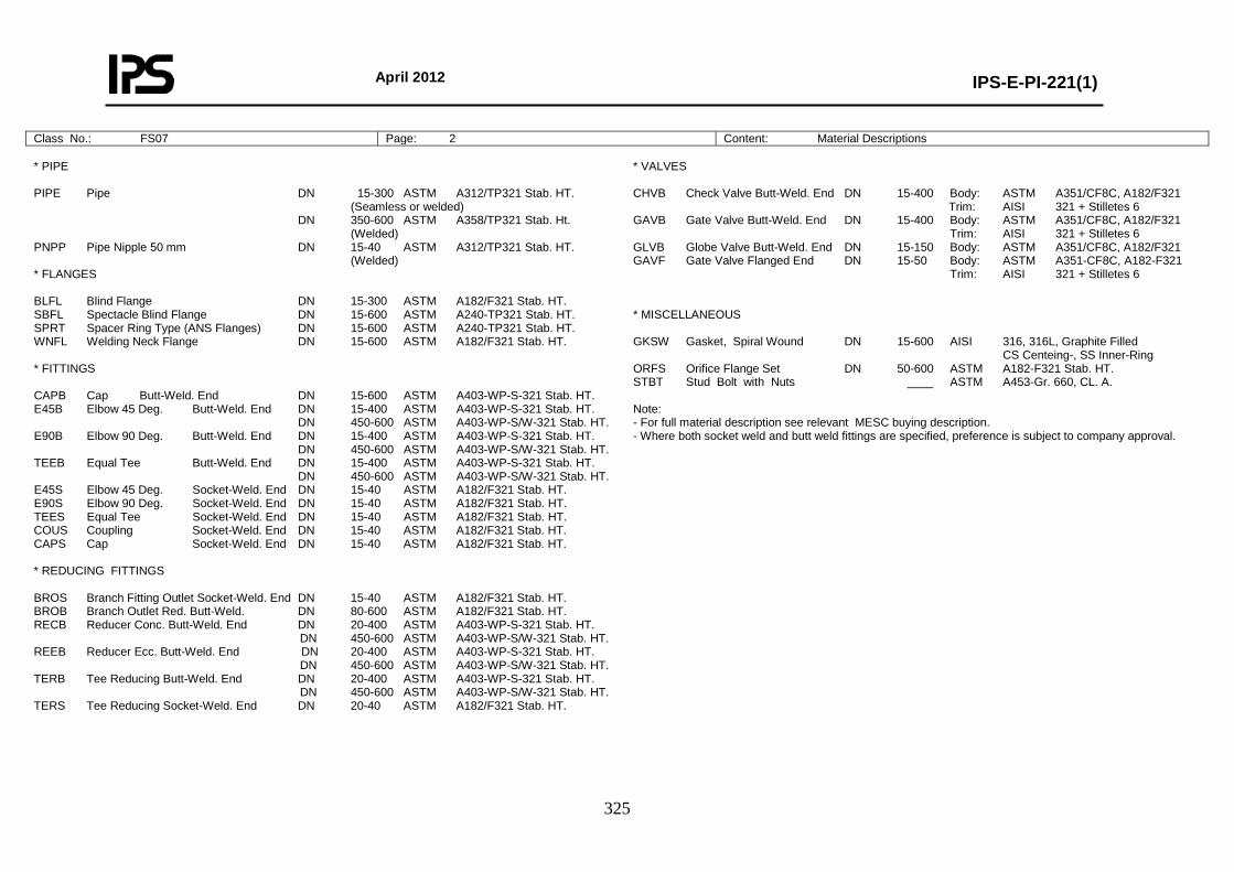
April 2012
IPS-E-PI-221(1)
325
Class No.: FS07 Page: 2 Content: Material Descriptions * PIPE PIPE Pipe DN 15-300 ASTM A312/TP321 Stab. HT. (Seamless or welded) DN 350-600 ASTM A358/TP321 Stab. Ht. (Welded) PNPP Pipe Nipple 50 mm DN 15-40 ASTM A312/TP321 Stab. HT. (Welded) * FLANGES BLFL Blind Flange DN 15-300 ASTM A182/F321 Stab. HT. SBFL Spectacle Blind Flange DN 15-600 ASTM A240-TP321 Stab. HT. SPRT Spacer Ring Type (ANS Flanges) DN 15-600 ASTM A240-TP321 Stab. HT. WNFL Welding Neck Flange DN 15-600 ASTM A182/F321 Stab. HT. * FITTINGS CAPB Cap Butt-Weld. End DN 15-600 ASTM A403-WP-S-321 Stab. HT. E45B Elbow 45 Deg. Butt-Weld. End DN 15-400 ASTM A403-WP-S-321 Stab. HT. DN 450-600 ASTM A403-WP-S/W-321 Stab. HT. E90B Elbow 90 Deg. Butt-Weld. End DN 15-400 ASTM A403-WP-S-321 Stab. HT. DN 450-600 ASTM A403-WP-S/W-321 Stab. HT. TEEB Equal Tee Butt-Weld. End DN 15-400 ASTM A403-WP-S-321 Stab. HT. DN 450-600 ASTM A403-WP-S/W-321 Stab. HT. E45S Elbow 45 Deg. Socket-Weld. End DN 15-40 ASTM A182/F321 Stab. HT. E90S Elbow 90 Deg. Socket-Weld. End DN 15-40 ASTM A182/F321 Stab. HT. TEES Equal Tee Socket-Weld. End DN 15-40 ASTM A182/F321 Stab. HT. COUS Coupling Socket-Weld. End DN 15-40 ASTM A182/F321 Stab. HT. CAPS Cap Socket-Weld. End DN 15-40 ASTM A182/F321 Stab. HT. * REDUCING FITTINGS BROS Branch Fitting Outlet Socket-Weld. End DN 15-40 ASTM A182/F321 Stab. HT. BROB Branch Outlet Red. Butt-Weld. DN 80-600 ASTM A182/F321 Stab. HT. RECB Reducer Conc. Butt-Weld. End DN 20-400 ASTM A403-WP-S-321 Stab. HT. DN 450-600 ASTM A403-WP-S/W-321 Stab. HT. REEB Reducer Ecc. Butt-Weld. End DN 20-400 ASTM A403-WP-S-321 Stab. HT. DN 450-600 ASTM A403-WP-S/W-321 Stab. HT. TERB Tee Reducing Butt-Weld. End DN 20-400 ASTM A403-WP-S-321 Stab. HT. DN 450-600 ASTM A403-WP-S/W-321 Stab. HT. TERS Tee Reducing Socket-Weld. End DN 20-40 ASTM A182/F321 Stab. HT.
* VALVES CHVB Check Valve Butt-Weld. End DN 15-400 Body: ASTM A351/CF8C, A182/F321 Trim: AISI 321 + Stilletes 6 GAVB Gate Valve Butt-Weld. End DN 15-400 Body: ASTM A351/CF8C, A182/F321 Trim: AISI 321 + Stilletes 6 GLVB Globe Valve Butt-Weld. End DN 15-150 Body: ASTM A351/CF8C, A182/F321 GAVF Gate Valve Flanged End DN 15-50 Body: ASTM A351-CF8C, A182-F321 Trim: AISI 321 + Stilletes 6 * MISCELLANEOUS GKSW Gasket, Spiral Wound DN 15-600 AISI 316, 316L, Graphite Filled CS Centeing-, SS Inner-Ring ORFS Orifice Flange Set DN 50-600 ASTM A182-F321 Stab. HT. STBT Stud Bolt with Nuts ____ ASTM A453-Gr. 660, CL. A. Note: - For full material description see relevant MESC buying description. - Where both socket weld and butt weld fittings are specified, preference is subject to company approval.

April 2012
IPS-E-PI-221(1)
326
Class No.: FS07 Page: 3 Content: Piping Components NOMINAL PIPE SIZE
ITEM DESCRIPTION 15 20 25 40 50 80 100 150 200 250 300 350 400 450 500 600
* PIPE Pipe 74.36.40 * * * * * * * * * * * * * * * * * FLANGES Blind Flange 76.65.10 * * * * * * * * * * * * * * * * Spectacle Blind Flange 76.88.07 * * * * * * * * * * * * * * * * Spacer Ring Type (ANS Flanges) 76.88.00 * * * * * * * * * * * * * * * * Welding Neck Flange 76.65.80 * * * * * * * * * * * * * * * * * FITTINGS Cap Butt-Weld. End 76.33.18 * * * * * * * * * * * * * * * * Elbow 45 Deg. Butt-Weld. End 76.33.38 * * * * * * * * * * * * * * * * Elbow 90 Deg. Butt-Weld. End 76.33.41 * * * * * * * * * * * * * * * * Equal Tee Butt-Weld. End 76.33.84 * * * * * * * * * * * * * * * * Elbow 45 Deg. Socket-Weld. End 76.34.38 * * * * Elbow 90 Deg. Socket-Weld. End 76.34.39 * * * * Equal Tee Socket-Weld. End 76.34.80 * * * * Coupling Socket-Weld. End 76.34.28 * * * * Cap Socket-Weld. End 76.34.18 * * * * * VALVES Check Valve Butt-Weld. End 75.58.15 * * * * * * * * * * * * * * * * Gate Valve Butt-Weld. End 75.58.35 * * * * * * * * * * * * * * * * Globe Valve Butt-Weld. End 75.58.45 * * * * * * * * * MISCELLANEOUS Gasket, Spiral Wound 85.41.37 * * * * * * * * * * * * * * * * Orifice Flange Se t 60.88.52 * * * * * * * * * * * *
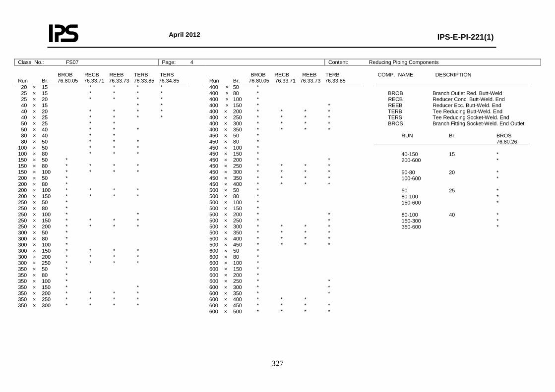
April 2012
IPS-E-PI-221(1)
327
Class No.: FS07 Page: 4 Content: Reducing Piping Components BROB RECB REEB TERB TERS Run Br. 76.80.05 76.33.71 76.33.73 76.33.85 76.34.85
BROB RECB REEB TERB Run Br. 76.80.05 76.33.71 76.33.73 76.33.85
COMP. NAME DESCRIPTION
20 × 15 * * * * 25 × 15 * * * * 25 × 20 * * * * 40 × 15 * * 40 × 20 * * * * 40 × 25 * * * * 50 × 25 * * 50 × 40 * * * 80 × 40 * * 80 × 50 * * * 100 × 50 * * * 100 × 80 * * * 150 × 50 * 150 × 80 * * * * 150 × 100 * * * * 200 × 50 * 200 × 80 * 200 × 100 * * * * 200 × 150 * * * * 250 × 50 * 250 × 80 * 250 × 100 * * 250 × 150 * * * * 250 × 200 * * * * 300 × 50 * 300 × 80 * 300 × 100 * 300 × 150 * * * * 300 × 200 * * * * 300 × 250 * * * * 350 × 50 * 350 × 80 * 350 × 100 * 350 × 150 * * 350 × 200 * * * * 350 × 250 * * * * 350 × 300 * * * *
400 × 50 * 400 × 80 * 400 × 100 * 400 × 150 * * 400 × 200 * * * * 400 × 250 * * * * 400 × 300 * * * * 400 × 350 * * * * 450 × 50 * 450 × 80 * 450 × 100 * 450 × 150 * 450 × 200 * * 450 × 250 * * * * 450 × 300 * * * * 450 × 350 * * * * 450 × 400 * * * * 500 × 50 * 500 × 80 * 500 × 100 * 500 × 150 * 500 × 200 * * 500 × 250 * * 500 × 300 * * * * 500 × 350 * * * * 500 × 400 * * * * 500 × 450 * * * * 600 × 50 * 600 × 80 * 600 × 100 * 600 × 150 * 600 × 200 * 600 × 250 * * 600 × 300 * * 600 × 350 * * 600 × 400 * * * 600 × 450 * * * * 600 × 500 * * * *
BROB Branch Outlet Red. Butt-Weld RECB Reducer Conc. Butt-Weld. End REEB Reducer Ecc. Butt-Weld. End TERB Tee Reducing Butt-Weld. End TERS Tee Reducing Socket-Weld. End BROS Branch Fitting Socket-Weld. End Outlet RUN Br. BROS 76.80.26 40-150 15 * 200-600 * 50-80 20 * 100-600 * 50 25 * 80-100 * 150-600 * 80-100 40 * 150-300 * 350-600 *
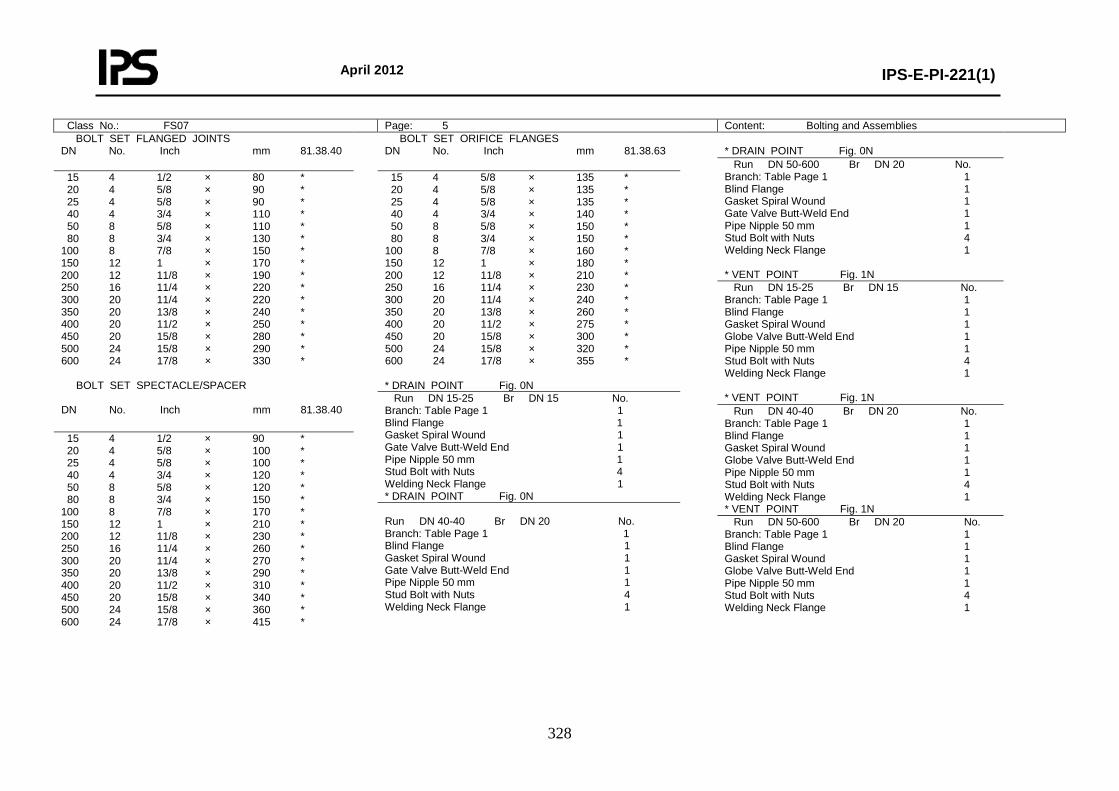
April 2012
IPS-E-PI-221(1)
328
Class No.: FS07 Page: 5 Content: Bolting and Assemblies BOLT SET FLANGED JOINTS DN No. Inch mm 81.38.40
BOLT SET ORIFICE FLANGES DN No. Inch mm 81.38.63
* DRAIN POINT Fig. 0N
Run DN 50-600 Br DN 20 No. Branch: Table Page 1 1 Blind Flange 1 Gasket Spiral Wound 1 Gate Valve Butt-Weld End 1 Pipe Nipple 50 mm 1 Stud Bolt with Nuts 4 Welding Neck Flange 1 * VENT POINT Fig. 1N
15 4 1/2 × 80 * 20 4 5/8 × 90 * 25 4 5/8 × 90 * 40 4 3/4 × 110 * 50 8 5/8 × 110 * 80 8 3/4 × 130 * 100 8 7/8 × 150 * 150 12 1 × 170 * 200 12 11/8 × 190 * 250 16 11/4 × 220 * 300 20 11/4 × 220 * 350 20 13/8 × 240 * 400 20 11/2 × 250 * 450 20 15/8 × 280 * 500 24 15/8 × 290 * 600 24 17/8 × 330 * BOLT SET SPECTACLE/SPACER DN No. Inch mm 81.38.40
15 4 5/8 × 135 * 20 4 5/8 × 135 * 25 4 5/8 × 135 * 40 4 3/4 × 140 * 50 8 5/8 × 150 * 80 8 3/4 × 150 * 100 8 7/8 × 160 * 150 12 1 × 180 * 200 12 11/8 × 210 * 250 16 11/4 × 230 * 300 20 11/4 × 240 * 350 20 13/8 × 260 * 400 20 11/2 × 275 * 450 20 15/8 × 300 * 500 24 15/8 × 320 * 600 24 17/8 × 355 * * DRAIN POINT Fig. 0N
Run DN 15-25 Br DN 15 No. Branch: Table Page 1 1 Blind Flange 1 Gasket Spiral Wound 1 Globe Valve Butt-Weld End 1 Pipe Nipple 50 mm 1 Stud Bolt with Nuts 4 Welding Neck Flange 1 * VENT POINT Fig. 1N Run DN 15-25 Br DN 15 No.
Branch: Table Page 1 1 Blind Flange 1 Gasket Spiral Wound 1 Gate Valve Butt-Weld End 1 Pipe Nipple 50 mm 1 Stud Bolt with Nuts 4 Welding Neck Flange 1 * DRAIN POINT Fig. 0N
Run DN 40-40 Br DN 20 No. Branch: Table Page 1 1 Blind Flange 1 Gasket Spiral Wound 1 Globe Valve Butt-Weld End 1 Pipe Nipple 50 mm 1 Stud Bolt with Nuts 4 Welding Neck Flange 1 * VENT POINT Fig. 1N
15 4 1/2 × 90 * 20 4 5/8 × 100 * 25 4 5/8 × 100 * 40 4 3/4 × 120 * 50 8 5/8 × 120 * 80 8 3/4 × 150 * 100 8 7/8 × 170 * 150 12 1 × 210 * 200 12 11/8 × 230 * 250 16 11/4 × 260 * 300 20 11/4 × 270 * 350 20 13/8 × 290 * 400 20 11/2 × 310 * 450 20 15/8 × 340 * 500 24 15/8 × 360 * 600 24 17/8 × 415 *
Run DN 40-40 Br DN 20 No. Branch: Table Page 1 1 Blind Flange 1 Gasket Spiral Wound 1 Gate Valve Butt-Weld End 1 Pipe Nipple 50 mm 1 Stud Bolt with Nuts 4 Welding Neck Flange 1
Run DN 50-600 Br DN 20 No. Branch: Table Page 1 1 Blind Flange 1 Gasket Spiral Wound 1 Globe Valve Butt-Weld End 1 Pipe Nipple 50 mm 1 Stud Bolt with Nuts 4 Welding Neck Flange 1
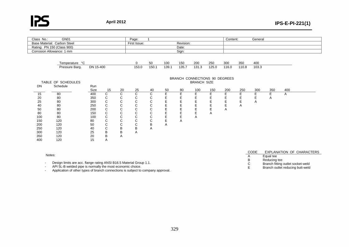
April 2012
IPS-E-PI-221(1)
329
Class No.: GN01 Page: 1 Content: General Base Material: Carbon Steel First Issue: Revision: Rating: PN 150 (Class 900) Date: Corrosion Allowance: 1 mm Sign:
Temperature °C 0 50 100 150 200 250 300 350 400 Pressure Barg. DN 15-400 153.0 150.1 139.1 135.7 131.3 125.0 116.0 110.8 103.3
TABLE OF SCHEDULES
BRANCH CONNECTIONS 90 DEGREES BRANCH SIZE
DN Schedule Run Size 15 20 25 40 50 80 100 150 200 250 300 350 400
15 20 25 40 50 80
100 150 200 250 300 350 400
80 80 80 80 80 80 80 120 120 120 120 120 120
400 C C C C E E E E E E E E A 350 C C C C E E E E E E E A 300 C C C C E E E E E E A 250 C C C C E E E E E A 200 C C C C E E E E A 150 C C C C E E E A 100 C C C C E E A 80 C C C C E A 50 C C C B A 40 C B B A 25 B B A 20 B A 15 A
Notes:
- Design limits are acc. flange rating ANSI B16.5 Material Group 1.1. - API 5L-B welded pipe is normally the most economic choice. - Application of other types of branch connections is subject to company approval.
CODE EXPLANATION OF CHARACTERS A Equal tee B Reducing tee C Branch fitting outlet socket-weld E Branch outlet reducing butt-weld
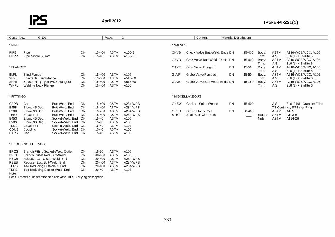
April 2012
IPS-E-PI-221(1)
330
Class No.: GN01 Page: 2 Content: Material Descriptions * PIPE PIPE Pipe DN 15-400 ASTM A106-B PNPP Pipe Nipple 50 mm DN 15-40 ASTM A106-B * FLANGES BLFL Blind Flange DN 15-400 ASTM A105 SBFL Spectacle Blind Flange DN 15-400 ASTM A516-60 SPRT Spacer Ring Type (ANS Flanges) DN 15-400 ASTM A516-60 WNFL Welding Neck Flange DN 15-400 ASTM A105 * FITTINGS CAPB Cap Butt-Weld. End DN 15-400 ASTM A234-WPB E45B Elbow 45 Deg. Butt-Weld. End DN 15-400 ASTM A234-WPB E90B Elbow 90 Deg. Butt-Weld. End DN 15-400 ASTM A234-WPB TEEB Equal Tee Butt-Weld. End DN 15-400 ASTM A234-WPB E45S Elbow 45 Deg. Socket-Weld. End DN 15-40 ASTM A105 E90S Elbow 90 Deg. Socket-Weld. End DN 15-40 ASTM A105 TEES Equal Tee Socket-Weld. End DN 15-40 ASTM A105 COUS Coupling Socket-Weld. End DN 15-40 ASTM A105 CAPS Cap Socket-Weld. End DN 15-40 ASTM A105 * REDUCING FITTINGS BROS Branch Fitting Socket-Weld. Outlet DN 15-50 ASTM A105 BROB Branch Outlet Red. Butt-Weld. DN 80-400 ASTM A105 RECB Reducer Conc. Butt-Weld. End DN 20-400 ASTM A234-WPB REEB Reducer Ecc. Butt-Weld. End DN 20-400 ASTM A234-WPB TERB Tee Reducing Butt-Weld. End DN 20-400 ASTM A234-WPB TERS Tee Reducing Socket-Weld. End DN 20-40 ASTM A105 Note: For full material description see relevant MESC buying description.
* VALVES CHVB Check Valve Butt-Weld. Ends DN 15-400 Body: ASTM A216-WCB/WCC, A105 Trim: AISI 316 (L) + Stellite 6 GAVB Gate Valve Butt-Weld. Ends DN 15-400 Body: ASTM A216-WCB/WCC, A105 Trim: AISI 316 (L) + Stellite 6 GAVF Gate Valve Flanged DN 15-50 Body: ASTM A216-WCB/WCC, A105 Trim: AISI 316 (L) + Stellite 6 GLVF Globe Valve Flanged DN 15-50 Body: ASTM A216-WCB/WCC, A105 Trim: AISI 316 (L) + Stellite 6 GLVB Globe Valve Butt-Weld. Ends DN 15-150 Body: ASTM A216-WCB/WCC, A105 Trim: AISI 316 (L) + Stellite 6 * MISCELLANEOUS GKSW Gasket, Spiral Wound DN 15-400 AISI 316, 316L, Graphite Filled CS Centring-, SS Inner-Ring ORFS Orifice Flange Set DN 50-400 ASTM A105 STBT Stud Bolt with Nuts ___ Studs: ASTM A193-B7 Nuts: ASTM A194-2H

April 2012
IPS-E-PI-221(1)
331
Class No.: GN01 Page: 3 Content: Piping Components NOMINAL PIPE SIZE
ITEM DESCRIPTION 15 20 25 40 50 80 100 150 200 250 300 350 400
* PIPE Pipe 74.30.21/31 * * * * * * * * * * * * * Pipe Nipple 50 mm 76.30.57 * * * * * FLANGES Blind Flange 76.62.10 * * * * * * * * * * * * * Spectacle Blind Flange 76.88.06 * * * * * * * * * * * * * Spacer Ring Type (ANS Flanges) 76.88.16 * * * * * * * * * * * * * Welding Neck Flange 76.62.79 * * * * * * * * * * * * * * FITTINGS Cap Butt-Weld. End 76.30.18 * * * * * * * * * * * * * Elbow 45 Deg. Butt-Weld. End 76.30.38 * * * * * * * * * * * * * Elbow 90 Deg. Butt-Weld. End 76.30.39/40 * * * * * * * * * * * * * Equal Tee Butt-Weld. End 76.30.84 * * * * * * * * * * * * * Elbow 45 Deg. Socket-Weld. End 76.34.38 * * * * Elbow 90 Deg. Socket-Weld. End 76.34.39 * * * * Equal Tee Socket-Weld. End 76.34.84 * * * * Coupling Socket-Weld. End 76.34.28 * * * * Cap Socket-Weld. End 76.34.18 * * * * * VALVES Check Valve Butt-Weld. End 75.56.16 * * * * * * * * * * * * * Gate Valve Butt-Weld. End 75.56.40 * * * * * * * * * * * * * Gate Valve Flanged 75.37.36 * * * * * Globe Valve Butt-Weld. End 75.56.54 * * * * * * * * Globe Valve Flanged 75.37.46 * * * * * * MISCELLANEOUS Gasket, Spiral Wound 85.41.37 * * * * * * * * * * * * * Orifice Flange Set 60.88.52 * * * * * * * * *
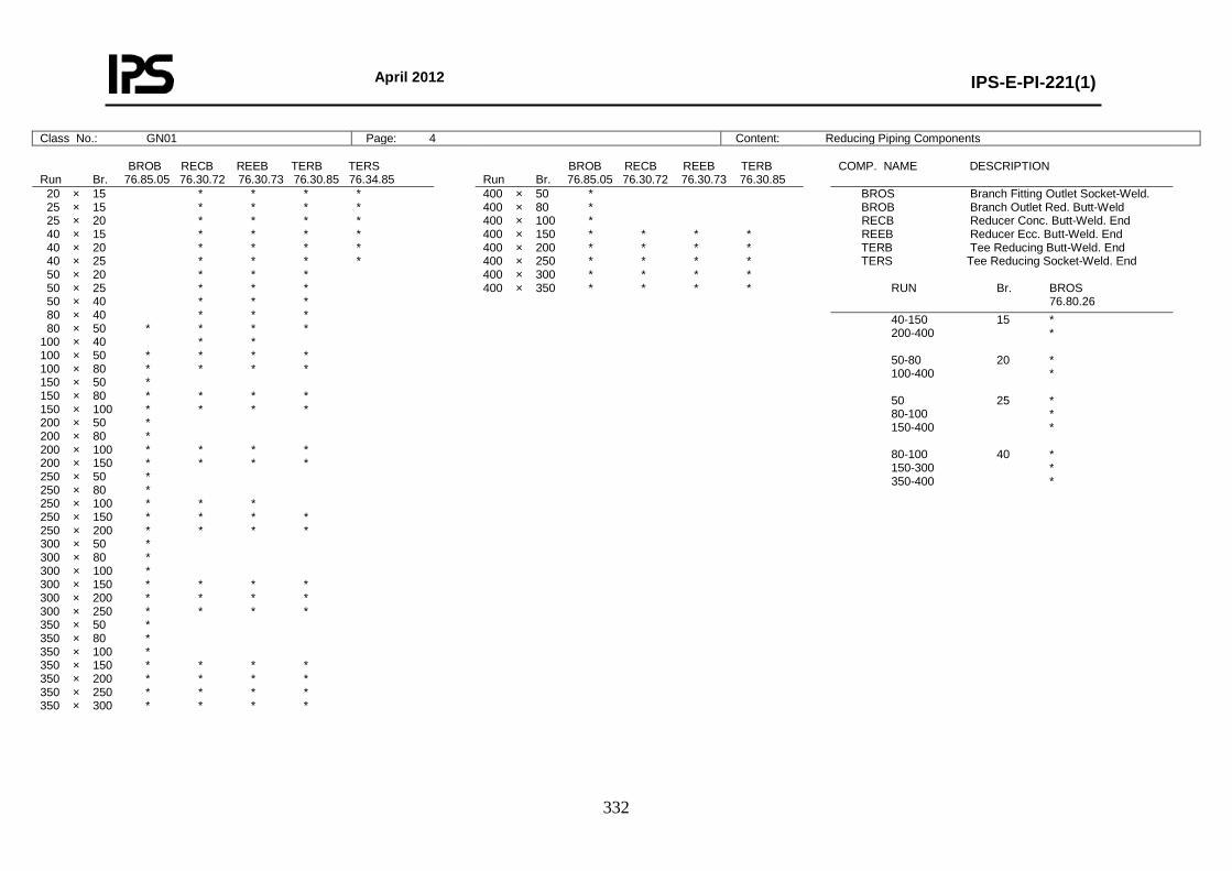
April 2012
IPS-E-PI-221(1)
332
Class No.: GN01 Page: 4 Content: Reducing Piping Components BROB RECB REEB TERB TERS Run Br. 76.85.05 76.30.72 76.30.73 76.30.85 76.34.85
BROB RECB REEB TERB Run Br. 76.85.05 76.30.72 76.30.73 76.30.85
COMP. NAME DESCRIPTION
20 × 15 * * * * 25 × 15 * * * * 25 × 20 * * * * 40 × 15 * * * * 40 × 20 * * * * 40 × 25 * * * * 50 × 20 * * * 50 × 25 * * * 50 × 40 * * * 80 × 40 * * * 80 × 50 * * * * 100 × 40 * * 100 × 50 * * * * 100 × 80 * * * * 150 × 50 * 150 × 80 * * * * 150 × 100 * * * * 200 × 50 * 200 × 80 * 200 × 100 * * * * 200 × 150 * * * * 250 × 50 * 250 × 80 * 250 × 100 * * * 250 × 150 * * * * 250 × 200 * * * * 300 × 50 * 300 × 80 * 300 × 100 * 300 × 150 * * * * 300 × 200 * * * * 300 × 250 * * * * 350 × 50 * 350 × 80 * 350 × 100 * 350 × 150 * * * * 350 × 200 * * * * 350 × 250 * * * * 350 × 300 * * * *
400 × 50 * 400 × 80 * 400 × 100 * 400 × 150 * * * * 400 × 200 * * * * 400 × 250 * * * * 400 × 300 * * * * 400 × 350 * * * *
BROS Branch Fitting Outlet Socket-Weld. BROB Branch Outlet Red. Butt-Weld RECB Reducer Conc. Butt-Weld. End REEB Reducer Ecc. Butt-Weld. End TERB Tee Reducing Butt-Weld. End TERS Tee Reducing Socket-Weld. End RUN Br. BROS 76.80.26 40-150 15 * 200-400 * 50-80 20 * 100-400 * 50 25 * 80-100 * 150-400 * 80-100 40 * 150-300 * 350-400 *

April 2012
IPS-E-PI-221(1)
333
Class No.: GN01 Page: 5 Content: Bolting and Assemblies BOLT SET FLANGED JOINTS DN No. Inch mm 81.38.61
BOLT SET ORIFICE FLANGES DN No. Inch mm 81.38.61
* DRAIN POINT Fig. 0N
Run DN 50-400 Br DN 20 No. Branch: Table Page 1 1 Blind Flange 1 Gasket Spiral Wound 1 Gate Valve Butt-Weld. Ends 1 Pipe Nipple 50 mm 1 Stud Bolt with Nuts 4 Welding Neck Flange 1 * VENT POINT Fig. 1N
15 4 3/4 × 110 * 20 4 3/4 × 110 * 25 4 7/8 × 130 * 40 4 1 × 140 * 50 8 7/8 × 150 * 80 8 7/8 × 150 * 100 8 11/8 × 170 * 150 12 11/8 × 190 * 200 12 13/8 × 220 * 250 16 13/8 × 240 * 300 20 13/8 × 250 * 350 20 11/2 × 275 * 400 20 15/8 × 290 * BOLT SET SPECTACLE/SPACER DN No. Inch mm 81.38.61
15 4 7/8 × 150 * 20 4 7/8 × 150 * 25 4 7/8 × 150 * 40 4 1 × 160 * 50 8 7/8 × 160 * 80 8 7/8 × 160 * 100 8 1-1/8 × 180 * 150 12 1-1/8 × 210 * 200 12 1-3/8 × 240 * 250 16 1-3/8 × 250 * 300 20 1-3/8 × 275 * 350 20 1-1/2 × 300 * 400 20 1-5/8 × 305 * * DRAIN POINT Fig. 0N
Run DN 15-25 Br DN 15 No. Branch: Table Page 1 1 Blind Flange 1 Gasket Spiral Wound 1 Globe Valve Butt-Weld. Ends 1 Pipe Nipple 50 mm 1 Stud Bolt with Nuts 4 Welding Neck Flange 1 * VENT POINT Fig. 1N
Run DN 15-25 Br DN 15 No. Branch: Table Page 1 1 Blind Flange 1 Gasket Spiral Wound 1 Gate Valve Butt-Weld. Ends 1 Pipe Nipple 50 mm 1 Stud Bolt with Nuts 4 Welding Neck Flange 1 * DRAIN POINT Fig. 0N
Run DN 40-40 Br DN 20 No. Branch: Table Page 1 1 Blind Flange 1 Gasket Spiral Wound 1 Globe Valve Butt-Weld. Ends 1 Pipe Nipple 50 mm 1 Stud Bolt with Nuts 4 Welding Neck Flange 1 * VENT POINT Fig. 1N
15 4 3/4 × 120 * 20 4 3/4 × 130 * 25 4 7/8 × 140 * 40 4 1 × 160 * 50 8 7/8 × 160 * 80 8 7/8 × 170 * 100 8 11/8 × 195 * 150 12 11/8 × 230 * 200 12 13/8 × 265 * 250 16 13/8 × 290 * 300 20 13/8 × 310 * 350 20 11/2 × 345 * 400 20 15/8 × 360 *
Run DN 40-40 Br DN 20 No. Branch: Table Page 1 1 Blind Flange 1 Gasket Spiral Wound 1 Gate Valve Butt-Weld. Ends 1 Pipe Nipple 50 mm 1 Stud Bolt with Nuts 4 Welding Neck Flange 1
Run DN 50-400 Br DN 20 No. Branch: Table Page 1 1 Blind Flange 1 Gasket Spiral Wound 1 Globe Valve Butt-Weld. Ends 1 Pipe Nipple 50 mm 1 Stud Bolt with Nuts 4 Welding Neck Flange 1
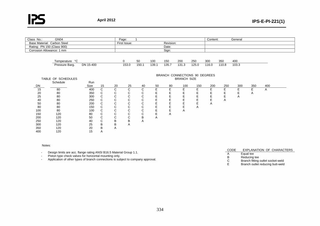
April 2012
IPS-E-PI-221(1)
334
Class No.: GN04 Page: 1 Content: General Base Material: Carbon Steel First Issue: Revision: Rating: PN 150 (Class 900) Date: Corrosion Allowance: 1 mm Sign:
Temperature °C 0 50 100 150 200 250 300 350 400 Pressure Barg. DN 15-400 153.0 150.1 139.1 135.7 131.3 125.0 116.0 110.8 103.3
TABLE OF SCHEDULES
BRANCH CONNECTIONS 90 DEGREES BRANCH SIZE
DN
Schedule Run Size 15 20 25 40 50 80 100 150 200 250 300 350 400
15 20 25 40 50 80 100 150 200 250 300 350 400
80 80 80 80 80 80 80 120 120 120 120 120 120
400 C C C C E E E E E E E E A 350 C C C C E E E E E E E A 300 C C C C E E E E E E A 250 C C C C E E E E E A 200 C C C C E E E E A 150 C C C C E E E A 100 C C C C E E A 80 C C C C E A 50 C C C B A 40 C B B A 25 B B A 20 B A 15 A
Notes:
- Design limits are acc. flange rating ANSI B16.5 Material Group 1.1. - Piston type check valves for horizontal mounting only. - Application of other types of branch connections is subject to company approval.
CODE EXPLANATION OF CHARACTERS A Equal tee B Reducing tee C Branch fitting outlet socket-weld E Branch outlet reducing butt-weld
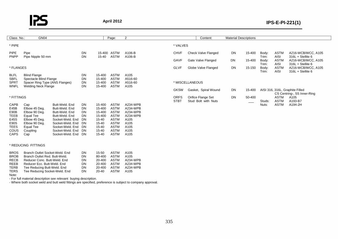
April 2012
IPS-E-PI-221(1)
335
Class No.: GN04 Page: 2 Content: Material Descriptions * PIPE PIPE Pipe DN 15-400 ASTM A106-B PNPP Pipe Nipple 50 mm DN 15-40 ASTM A106-B * FLANGES BLFL Blind Flange DN 15-400 ASTM A105 SBFL Spectacle Blind Flange DN 15-400 ASTM A516-60 SPRT Spacer Ring Type (ANS Flanges) DN 15-400 ASTM A516-60 WNFL Welding Neck Flange DN 15-400 ASTM A105 * FITTINGS CAPB Cap Butt-Weld. End DN 15-400 ASTM A234-WPB E45B Elbow 45 Deg. Butt-Weld. End DN 15-400 ASTM A234-WPB E90B Elbow 90 Deg. Butt-Weld. End DN 15-400 ASTM A234-WPB TEEB Equal Tee Butt-Weld. End DN 15-400 ASTM A234-WPB E45S Elbow 45 Deg. Socket-Weld. End DN 15-40 ASTM A105 E90S Elbow 90 Deg. Socket-Weld. End DN 15-40 ASTM A105 TEES Equal Tee Socket-Weld. End DN 15-40 ASTM A105 COUS Coupling Socket-Weld. End DN 15-40 ASTM A105 CAPS Cap Socket-Weld. End DN 15-40 ASTM A105 * REDUCING FITTINGS BROS Branch Outlet Socket-Weld. End DN 15-50 ASTM A105 BROB Branch Outlet Red. Butt-Weld. DN 80-400 ASTM A105 RECB Reducer Conc. Butt-Weld. End DN 20-400 ASTM A234-WPB REEB Reducer Ecc. Butt-Weld. End DN 20-400 ASTM A234-WPB TERB Tee Reducing Butt-Weld. End DN 20-400 ASTM A234-WPB TERS Tee Reducing Socket-Weld. End DN 20-40 ASTM A105 Note: - For full material description see relevant buying description. - Where both socket weld and butt weld fittings are specified, preference is subject to company approval.
* VALVES CHVF Check Valve Flanged DN 15-400 Body: ASTM A216-WCB/WCC, A105 Trim: AISI 316L + Stellite 6 GAVF Gate Valve Flanged DN 15-400 Body: ASTM A216-WCB/WCC, A105 Trim: AISI 316L + Stellite 6 GLVF Globe Valve Flanged DN 15-150 Body: ASTM A216-WCB/WCC, A105 Trim: AISI 316L + Stellite 6 * MISCELLANEOUS GKSW Gasket, Spiral Wound DN 15-400 AISI 316, 316L, Graphite Filled CS Centring-, SS Inner-Ring ORFS Orifice Flange Set DN 50-400 ASTM A105 STBT Stud Bolt with Nuts ___ Studs: ASTM A193-B7 Nuts: ASTM A194-2H
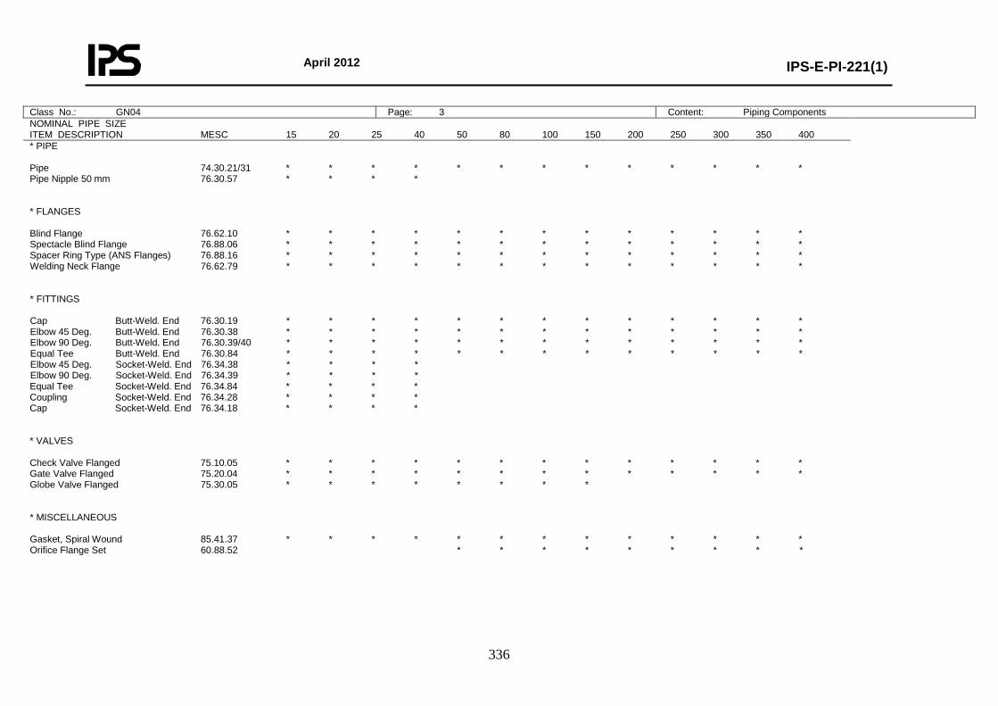
April 2012
IPS-E-PI-221(1)
336
Class No.: GN04 Page: 3 Content: Piping Components NOMINAL PIPE SIZE ITEM DESCRIPTION MESC 15 20 25 40 50 80 100 150 200 250 300 350 400
* PIPE Pipe 74.30.21/31 * * * * * * * * * * * * * Pipe Nipple 50 mm 76.30.57 * * * * * FLANGES Blind Flange 76.62.10 * * * * * * * * * * * * * Spectacle Blind Flange 76.88.06 * * * * * * * * * * * * * Spacer Ring Type (ANS Flanges) 76.88.16 * * * * * * * * * * * * * Welding Neck Flange 76.62.79 * * * * * * * * * * * * * * FITTINGS Cap Butt-Weld. End 76.30.19 * * * * * * * * * * * * * Elbow 45 Deg. Butt-Weld. End 76.30.38 * * * * * * * * * * * * * Elbow 90 Deg. Butt-Weld. End 76.30.39/40 * * * * * * * * * * * * * Equal Tee Butt-Weld. End 76.30.84 * * * * * * * * * * * * * Elbow 45 Deg. Socket-Weld. End 76.34.38 * * * * Elbow 90 Deg. Socket-Weld. End 76.34.39 * * * * Equal Tee Socket-Weld. End 76.34.84 * * * * Coupling Socket-Weld. End 76.34.28 * * * * Cap Socket-Weld. End 76.34.18 * * * * * VALVES Check Valve Flanged 75.10.05 * * * * * * * * * * * * * Gate Valve Flanged 75.20.04 * * * * * * * * * * * * * Globe Valve Flanged 75.30.05 * * * * * * * * * MISCELLANEOUS Gasket, Spiral Wound 85.41.37 * * * * * * * * * * * * * Orifice Flange Set 60.88.52 * * * * * * * * *
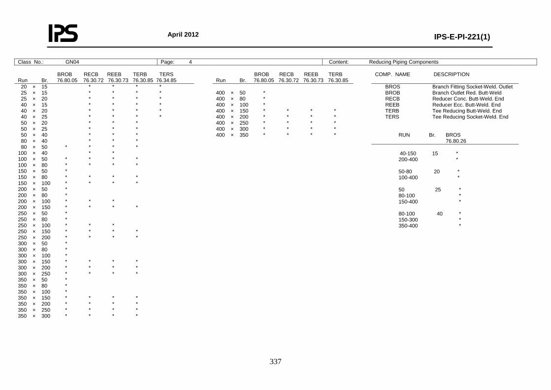
April 2012
IPS-E-PI-221(1)
337
Class No.: GN04 Page: 4 Content: Reducing Piping Components BROB RECB REEB TERB TERS Run Br. 76.80.05 76.30.72 76.30.73 76.30.85 76.34.85
BROB RECB REEB TERB Run Br. 76.80.05 76.30.72 76.30.73 76.30.85
COMP. NAME DESCRIPTION
20 × 15 * * * * 25 × 15 * * * * 25 × 20 * * * * 40 × 15 * * * * 40 × 20 * * * * 40 × 25 * * * * 50 × 20 * * * 50 × 25 * * * 50 × 40 * * * 80 × 40 * * * 80 × 50 * * * * 100 × 40 * * 100 × 50 * * * * 100 × 80 * * * * 150 × 50 * 150 × 80 * * * * 150 × 100 * * * * 200 × 50 * 200 × 80 * 200 × 100 * * * 200 × 150 * * * * 250 × 50 * 250 × 80 * 250 × 100 * * * 250 × 150 * * * * 250 × 200 * * * * 300 × 50 * 300 × 80 * 300 × 100 * 300 × 150 * * * * 300 × 200 * * * * 300 × 250 * * * * 350 × 50 * 350 × 80 * 350 × 100 * 350 × 150 * * * * 350 × 200 * * * * 350 × 250 * * * * 350 × 300 * * * *
400 × 50 * 400 × 80 * 400 × 100 * 400 × 150 * * * * 400 × 200 * * * * 400 × 250 * * * * 400 × 300 * * * * 400 × 350 * * * *
BROS Branch Fitting Socket-Weld. Outlet BROB Branch Outlet Red. Butt-Weld RECB Reducer Conc. Butt-Weld. End REEB Reducer Ecc. Butt-Weld. End TERB Tee Reducing Butt-Weld. End TERS Tee Reducing Socket-Weld. End RUN Br. BROS 76.80.26 40-150 15 * 200-400 * 50-80 20 * 100-400 * 50 25 * 80-100 * 150-400 * 80-100 40 * 150-300 * 350-400 *
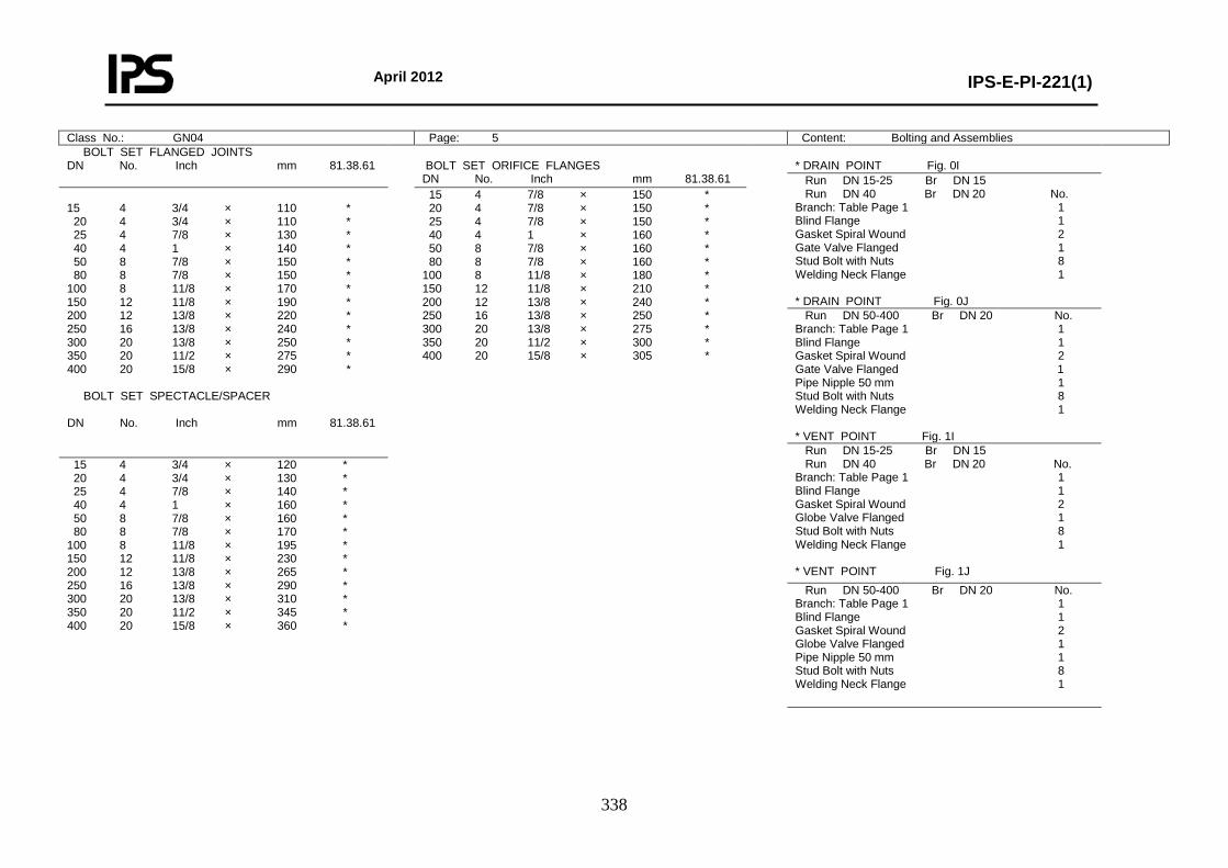
April 2012
IPS-E-PI-221(1)
338
Class No.: GN04 Page: 5 Content: Bolting and Assemblies BOLT SET FLANGED JOINTS DN No. Inch mm 81.38.61
BOLT SET ORIFICE FLANGES DN No. Inch mm 81.38.61
* DRAIN POINT Fig. 0I
Run DN 15-25 Br DN 15 Run DN 40 Br DN 20 No. Branch: Table Page 1 1 Blind Flange 1 Gasket Spiral Wound 2 Gate Valve Flanged 1 Stud Bolt with Nuts 8 Welding Neck Flange 1 * DRAIN POINT Fig. 0J
15 4 3/4 × 110 * 20 4 3/4 × 110 * 25 4 7/8 × 130 * 40 4 1 × 140 * 50 8 7/8 × 150 * 80 8 7/8 × 150 * 100 8 11/8 × 170 * 150 12 11/8 × 190 * 200 12 13/8 × 220 * 250 16 13/8 × 240 * 300 20 13/8 × 250 * 350 20 11/2 × 275 * 400 20 15/8 × 290 * BOLT SET SPECTACLE/SPACER DN No. Inch mm 81.38.61
15 4 7/8 × 150 * 20 4 7/8 × 150 * 25 4 7/8 × 150 * 40 4 1 × 160 * 50 8 7/8 × 160 * 80 8 7/8 × 160 * 100 8 11/8 × 180 * 150 12 11/8 × 210 * 200 12 13/8 × 240 * 250 16 13/8 × 250 * 300 20 13/8 × 275 * 350 20 11/2 × 300 * 400 20 15/8 × 305 *
Run DN 50-400 Br DN 20 No. Branch: Table Page 1 1 Blind Flange 1 Gasket Spiral Wound 2 Gate Valve Flanged 1 Pipe Nipple 50 mm 1 Stud Bolt with Nuts 8 Welding Neck Flange 1 * VENT POINT Fig. 1I Run DN 15-25 Br DN 15 Run DN 40 Br DN 20 No. Branch: Table Page 1 1 Blind Flange 1 Gasket Spiral Wound 2 Globe Valve Flanged 1 Stud Bolt with Nuts 8 Welding Neck Flange 1 * VENT POINT Fig. 1J
15 4 3/4 × 120 * 20 4 3/4 × 130 * 25 4 7/8 × 140 * 40 4 1 × 160 * 50 8 7/8 × 160 * 80 8 7/8 × 170 * 100 8 11/8 × 195 * 150 12 11/8 × 230 * 200 12 13/8 × 265 * 250 16 13/8 × 290 * 300 20 13/8 × 310 * 350 20 11/2 × 345 * 400 20 15/8 × 360 *
Run DN 50-400 Br DN 20 No. Branch: Table Page 1 1 Blind Flange 1 Gasket Spiral Wound 2 Globe Valve Flanged 1 Pipe Nipple 50 mm 1 Stud Bolt with Nuts 8 Welding Neck Flange 1
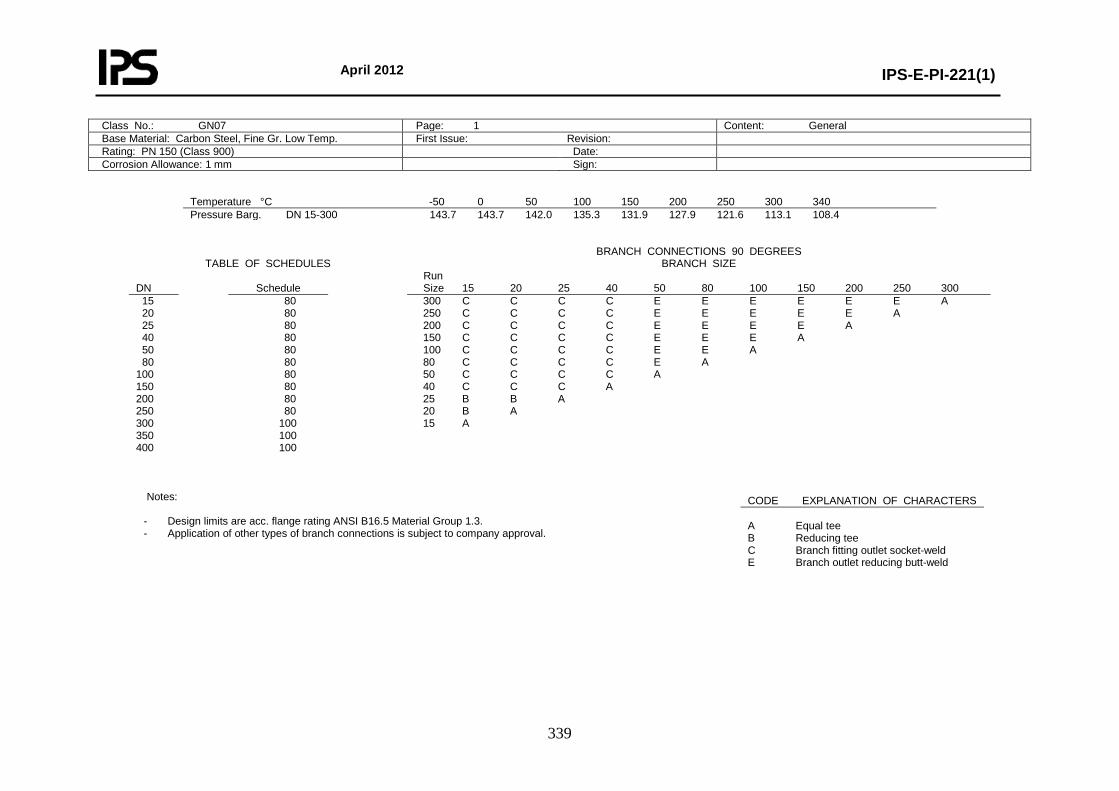
April 2012
IPS-E-PI-221(1)
339
Class No.: GN07 Page: 1 Content: General Base Material: Carbon Steel, Fine Gr. Low Temp. First Issue: Revision: Rating: PN 150 (Class 900) Date: Corrosion Allowance: 1 mm Sign:
Temperature °C -50 0 50 100 150 200 250 300 340 Pressure Barg. DN 15-300 143.7 143.7 142.0 135.3 131.9 127.9 121.6 113.1 108.4
TABLE OF SCHEDULES
BRANCH CONNECTIONS 90 DEGREES BRANCH SIZE
DN
Schedule
Run Size 15 20 25 40 50 80 100 150 200 250 300
15 20 25 40 50 80 100 150 200 250 300 350 400
80 80 80 80 80 80 80 80 80 80
100 100 100
300 C C C C E E E E E E A 250 C C C C E E E E E A 200 C C C C E E E E A 150 C C C C E E E A 100 C C C C E E A 80 C C C C E A 50 C C C C A 40 C C C A 25 B B A 20 B A 15 A
Notes:
- Design limits are acc. flange rating ANSI B16.5 Material Group 1.3. - Application of other types of branch connections is subject to company approval.
CODE EXPLANATION OF CHARACTERS A Equal tee B Reducing tee C Branch fitting outlet socket-weld E Branch outlet reducing butt-weld
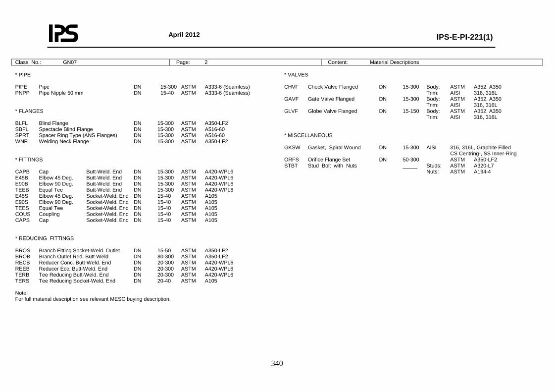
April 2012
IPS-E-PI-221(1)
340
Class No.: GN07 Page: 2 Content: Material Descriptions * PIPE PIPE Pipe DN 15-300 ASTM A333-6 (Seamless) PNPP Pipe Nipple 50 mm DN 15-40 ASTM A333-6 (Seamless) * FLANGES BLFL Blind Flange DN 15-300 ASTM A350-LF2 SBFL Spectacle Blind Flange DN 15-300 ASTM A516-60 SPRT Spacer Ring Type (ANS Flanges) DN 15-300 ASTM A516-60 WNFL Welding Neck Flange DN 15-300 ASTM A350-LF2 * FITTINGS CAPB Cap Butt-Weld. End DN 15-300 ASTM A420-WPL6 E45B Elbow 45 Deg. Butt-Weld. End DN 15-300 ASTM A420-WPL6 E90B Elbow 90 Deg. Butt-Weld. End DN 15-300 ASTM A420-WPL6 TEEB Equal Tee Butt-Weld. End DN 15-300 ASTM A420-WPL6 E45S Elbow 45 Deg. Socket-Weld. End DN 15-40 ASTM A105 E90S Elbow 90 Deg. Socket-Weld. End DN 15-40 ASTM A105 TEES Equal Tee Socket-Weld. End DN 15-40 ASTM A105 COUS Coupling Socket-Weld. End DN 15-40 ASTM A105 CAPS Cap Socket-Weld. End DN 15-40 ASTM A105 * REDUCING FITTINGS BROS Branch Fitting Socket-Weld. Outlet DN 15-50 ASTM A350-LF2 BROB Branch Outlet Red. Butt-Weld. DN 80-300 ASTM A350-LF2 RECB Reducer Conc. Butt-Weld. End DN 20-300 ASTM A420-WPL6 REEB Reducer Ecc. Butt-Weld. End DN 20-300 ASTM A420-WPL6 TERB Tee Reducing Butt-Weld. End DN 20-300 ASTM A420-WPL6 TERS Tee Reducing Socket-Weld. End DN 20-40 ASTM A105 Note: For full material description see relevant MESC buying description.
* VALVES CHVF Check Valve Flanged DN 15-300 Body: ASTM A352, A350 Trim: AISI 316, 316L GAVF Gate Valve Flanged DN 15-300 Body: ASTM A352, A350 Trim: AISI 316, 316L GLVF Globe Valve Flanged DN 15-150 Body: ASTM A352, A350 Trim: AISI 316, 316L * MISCELLANEOUS GKSW Gasket, Spiral Wound DN 15-300 AISI 316, 316L, Graphite Filled CS Centring-, SS Inner-Ring ORFS Orifice Flange Set DN 50-300 ASTM A350-LF2 STBT Stud Bolt with Nuts _____ Studs: ASTM A320-L7 Nuts: ASTM A194-4
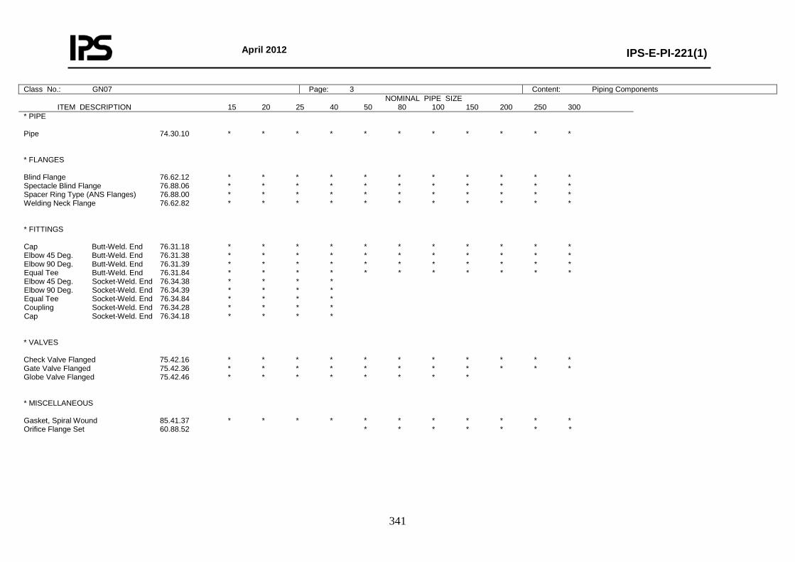
April 2012
IPS-E-PI-221(1)
341
Class No.: GN07 Page: 3 Content: Piping Components NOMINAL PIPE SIZE
ITEM DESCRIPTION 15 20 25 40 50 80 100 150 200 250 300
* PIPE Pipe 74.30.10 * * * * * * * * * * * * FLANGES Blind Flange 76.62.12 * * * * * * * * * * * Spectacle Blind Flange 76.88.06 * * * * * * * * * * * Spacer Ring Type (ANS Flanges) 76.88.00 * * * * * * * * * * * Welding Neck Flange 76.62.82 * * * * * * * * * * * * FITTINGS Cap Butt-Weld. End 76.31.18 * * * * * * * * * * * Elbow 45 Deg. Butt-Weld. End 76.31.38 * * * * * * * * * * * Elbow 90 Deg. Butt-Weld. End 76.31.39 * * * * * * * * * * * Equal Tee Butt-Weld. End 76.31.84 * * * * * * * * * * * Elbow 45 Deg. Socket-Weld. End 76.34.38 * * * * Elbow 90 Deg. Socket-Weld. End 76.34.39 * * * * Equal Tee Socket-Weld. End 76.34.84 * * * * Coupling Socket-Weld. End 76.34.28 * * * * Cap Socket-Weld. End 76.34.18 * * * * * VALVES Check Valve Flanged 75.42.16 * * * * * * * * * * * Gate Valve Flanged 75.42.36 * * * * * * * * * * * Globe Valve Flanged 75.42.46 * * * * * * * * * MISCELLANEOUS Gasket, Spiral Wound 85.41.37 * * * * * * * * * * * Orifice Flange Set 60.88.52 * * * * * * *
April 2012
IPS-E-PI-221(1)
342
Class No.: GN07 Page: 4 Content: Reducing Piping Components BROB RECB REEB TERB TERS Run Br. 76.31.70 76.31.71 76.31.85 76.34.85
COMP. NAME DESCRIPTION
20 × 15 * * * * 25 × 15 * * * * 25 × 20 * * * * 40 × 15 * * 40 × 20 * * * * 40 × 25 * * * * 50 × 20 * * 50 × 25 * * * 50 × 40 * * * 80 × 40 * * * 80 × 50 * * * * 100 × 40 * 100 × 50 * * * * 100 × 80 * * * * 150 × 50 * 150 × 80 * * * * 150 × 100 * * * * 200 × 50 * 200 × 80 * 200 × 100 * * * * 200 × 150 * * * * 250 × 50 * 250 × 80 * 250 × 100 * * 250 × 150 * * * * 250 × 200 * * * * 300 × 50 * 300 × 80 * 300 × 100 * 300 × 150 * * 300 × 200 * * * * 300 × 250 * * * *
BROS Branch Fitting Outlet Socket-Weld BROB Branch Outlet Red. Butt-Weld RECB Reducer Conc. Butt-Weld. End REEB Reducer Ecc. Butt-Weld. End TERB Tee Reducing Butt-Weld. End TERS Tee Reducing Socket-Weld. End RUN Br. BROS 76.80.26 40-150 15 * 200-300 * 50-80 20 * 100-300 * 50 25 * 80-100 * 150-300 * 80-100 40 * 150-300 *
April 2012
IPS-E-PI-221(1)
343
Class No.: GN07 Page: 5 Content: Bolting and Assemblies BOLT SET FLANGED JOINTS DN No. Inch mm 81.38.63
BOLT SET ORIFICE FLANGES DN No. Inch mm 81.38.63
* DRAIN POINT Fig. 0J
Run DN 50-300 Br DN 20 No. Branch: Table Page 1 1 Blind Flange 1 Gasket Spiral Wound 2 Gate Valve Flanged 1 Pipe Nipple 50 mm 1 Stud Bolt with Nuts 8 Welding Neck Flange 1 * VENT POINT Fig. 1J
15 4 3/4 × 110 * 20 4 3/4 × 110 * 25 4 7/8 × 125 * 40 4 1 × 140 * 50 8 7/8 × 145 * 80 8 7/8 × 145 * 100 8 11/8 × 170 * 150 12 11/8 × 190 * 200 12 13/8 × 220 * 250 16 13/8 × 235 * 300 20 13/8 × 250 * BOLT SET SPECTACLE/SPACER DN No. Inch mm 81.38.63
15 4 7/8 × 150 * 20 4 7/8 × 150 * 25 4 7/8 × 150 * 40 4 1 × 160 * 50 8 7/8 × 160 * 80 8 7/8 × 160 * 100 8 1-1/8 × 180 * 150 12 1-1/8 × 210 * 200 12 1-3/8 × 240 * 250 16 1-3/8 × 250 * 300 20 1-3/8 × 275 * * DRAIN POINT Fig. 0J
Run DN 15-25 Br DN 15 No. Branch: Table Page 1 1 Blind Flange 1 Gasket Spiral Wound 2 Globe Valve Flanged 1 Pipe Nipple 50 mm 1 Stud Bolt with Nuts 8 Welding Neck Flange 1 * VENT POINT Fig. 1J
Run DN 15-25 Br DN 15 No. Branch: Table Page 1 1 Blind Flange 1 Gasket Spiral Wound 2 Gate Valve Flanged 1 Pipe Nipple 50 mm 1 Stud Bolt with Nuts 8 Welding Neck Flange 1 * DRAIN POINT Fig. 0J
15 4 3/4 × 115 * 20 4 3/4 × 125 * 25 4 7/8 × 140 * 40 4 1 × 160 * 50 8 7/8 × 160 * 80 8 7/8 × 165 * 100 8 11/8 × 195 * 150 12 11/8 × 230 * 200 12 13/8 × 265 * 250 16 13/8 × 285 * 300 20 13/8 × 310 *
Run DN 40-40 Br DN 20 No. Branch: Table Page 1 1 Blind Flange 1 Gasket Spiral Wound 2 Globe Valve Flanged 1 Pipe Nipple 50 mm 1 Stud Bolt with Nuts 8 Welding Neck Flange 1 * VENT POINT Fig. 1J
Run DN 40-40 Br DN 20 No. Branch: Table Page 1 1 Blind Flange 1 Gasket Spiral Wound 2 Gate Valve Flanged 1 Pipe Nipple 50 mm 1 Stud Bolt with Nuts 8 Welding Neck Flange 1
Run DN 50-300 Br DN 20 No. Branch: Table Page 1 1 Blind Flange 1 Gasket Spiral Wound 2 Globe Valve Flanged 1 Pipe Nipple 50 mm 1 Stud Bolt with Nuts 8 Welding Neck Flange 1
April 2012
IPS-E-PI-221(1)
344
Class No.: GN10 Page: 1 Content: General Base Material: Carbon Steel First Issue: Revision: Rating: PN 150 (Class 900) Date: Corrosion Allowance: 1 mm Sign:
Temperature °C 0 50 100 150 200 250 300 350 400 Pressure Barg. DN 15-400 153.0 150.1 139.1 135.7 131.3 125.0 116.0 110.8 103.3
TABLE OF SCHEDULES
BRANCH CONNECTIONS 90 DEGREES BRANCH SIZE
DN
Schedule
Run Size 15 20 25 40 50 80 100 150 200 250 300 350 400
15 20 25 40 50 80
100 150 200 250 300 350 400
80 80 80 80 80 80 80 120 120 120 120 120 120
400 C C C C E E E E E E E E A 350 C C C C E E E E E E E A 300 C C C C E E E E E E A 250 C C C C E E E E E A 200 C C C C E E E E A 150 C C C C E E E A 100 C C C C E E A 80 C C C C E A 50 C C C B A 40 C B B A 25 B B A 20 B A 15 A
Notes:
- Design limits are acc. flange rating ANSI B16.5 Material Group 1.1. - API 5L-B welded pipe is normally the most economic choice. - Application of other types of branch connections is subject to company approval. - Piston type check valves for horizontal mounting only.
CODE EXPLANATION OF CHARACTERS A Equal tee B Reducing tee C Branch fitting outlet socket-weld E Branch outlet reducing butt-weld
April 2012
IPS-E-PI-221(1)
345
Class No.: GN10 Page: 2 Content: Material Descriptions * PIPE PIPE Pipe DN 15-400 ASTM A106-B PNPP Pipe Nipple 50 mm DN 15-40 ASTM A106-B * FLANGES BLFL Blind Flange DN 15-400 ASTM A105 SBFL Spectacle Blind Flange DN 15-400 ASTM A516-60 SPRT Spacer Ring Type (ANS Flanges) DN 15-400 ASTM A516-60 WNFL Welding Neck Flange DN 15-400 ASTM A105 * FITTINGS CAPB Cap Butt-Weld. End DN 15-400 ASTM A234-WPB E45B Elbow 45 Deg. Butt-Weld. End DN 15-400 ASTM A234-WPB E90B Elbow 90 Deg. Butt-Weld. End DN 15-400 ASTM A234-WPB TEEB Equal Tee Butt-Weld. End DN 15-400 ASTM A234-WPB E45S Elbow 45 Deg. Socket-Weld. End DN 15-40 ASTM A105 E90S Elbow 90 Deg. Socket-Weld. End DN 15-40 ASTM A105 TEES Equal Tee Socket-Weld. End DN 15-40 ASTM A105 COUS Coupling Socket-Weld. End DN 15-40 ASTM A105 CAPS Cap Socket-Weld. End DN 15-40 ASTM A105 * REDUCING FITTINGS BROS Branch Fitting Socket-Weld. Outlet DN 15-50 ASTM A105 BROB Branch Outlet Red. Butt-Weld. DN 15-400 ASTM A105 RECB Reducer Conc. Butt-Weld. End DN 20-400 ASTM A234-WPB REEB Reducer Ecc. Butt-Weld. End DN 20-400 ASTM A234-WPB TERB Tee Reducing Butt-Weld. End DN 20-400 ASTM A234-WPB TERS Tee Reducing Socket-Weld. End DN 20-40 ASTM A105 Note: For full material description see relevant MESC buying description.
* VALVES CHVF Check Valve Flanged DN 15-40 Body: ASTM A216-WCB/WCC, A105 Trim: AISI 316 (L) + Stellite 6 DN 50-400 Body: ASTM A216-WCB/WCC, A105 Trim: AISI 410 GAVF Gate Valve Flanged DN 15-40 Body: ASTM A216-WCB/WCC, A105 Trim: AISI 316 (L) + Stellite 6 DN 50-400 Body: ASTM A216-WCB/WCC, A105 Trim: AISI 410 GLVF Globe Valve Flanged DN 15-40 Body: ASTM A216-WCB/WCC, A105 Trim: AISI 316 (L) + Stellite 6 DN 50-150 Body: ASTM A216-WCB/WCC, A105 Trim: AISI 410 * MISCELLANEOUS GKSW Gasket, Spiral Wound DN 15-400 AISI 316, 316L, Graphite Filled CS Centring-, SS Inner-Ring ORFS Orifice Flange Set DN 50-400 ASTM A105 STBT Stud Bolt with Nuts ______ Studs: ASTM A193-B7 Nuts: ASTM A194-2H
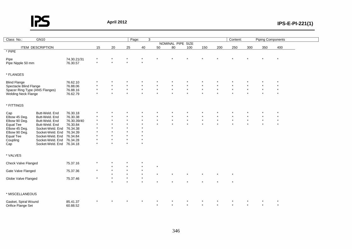
April 2012
IPS-E-PI-221(1)
346
Class No.: GN10 Page: 3 Content: Piping Components NOMINAL PIPE SIZE
ITEM DESCRIPTION 15 20 25 40 50 80 100 150 200 250 300 350 400
* PIPE Pipe 74.30.21/31 * * * * * * * * * * * * * Pipe Nipple 50 mm 76.30.57 * * * * * FLANGES Blind Flange 76.62.10 * * * * * * * * * * * * * Spectacle Blind Flange 76.88.06 * * * * * * * * * * * * * Spacer Ring Type (ANS Flanges) 76.88.16 * * * * * * * * * * * * * Welding Neck Flange 76.62.79 * * * * * * * * * * * * * * FITTINGS Cap Butt-Weld. End 76.30.18 * * * * * * * * * * * * * Elbow 45 Deg. Butt-Weld. End 76.30.38 * * * * * * * * * * * * * Elbow 90 Deg. Butt-Weld. End 76.30.39/40 * * * * * * * * * * * * * Equal Tee Butt-Weld. End 76.30.84 * * * * * * * * * * * * * Elbow 45 Deg. Socket-Weld. End 76.34.38 * * * * Elbow 90 Deg. Socket-Weld. End 76.34.39 * * * * Equal Tee Socket-Weld. End 76.34.84 * * * * Coupling Socket-Weld. End 76.34.28 * * * * Cap Socket-Weld. End 76.34.18 * * * * * VALVES Check Valve Flanged 75.37.16 * * * * * * * * Gate Valve Flanged 75.37.36 * * * * * * * * * * * * * Globe Valve Flanged 75.37.46 * * * * * * * * * * * * * * MISCELLANEOUS Gasket, Spiral Wound 85.41.37 * * * * * * * * * * * * * Orifice Flange Set 60.88.52 * * * * * * * * *
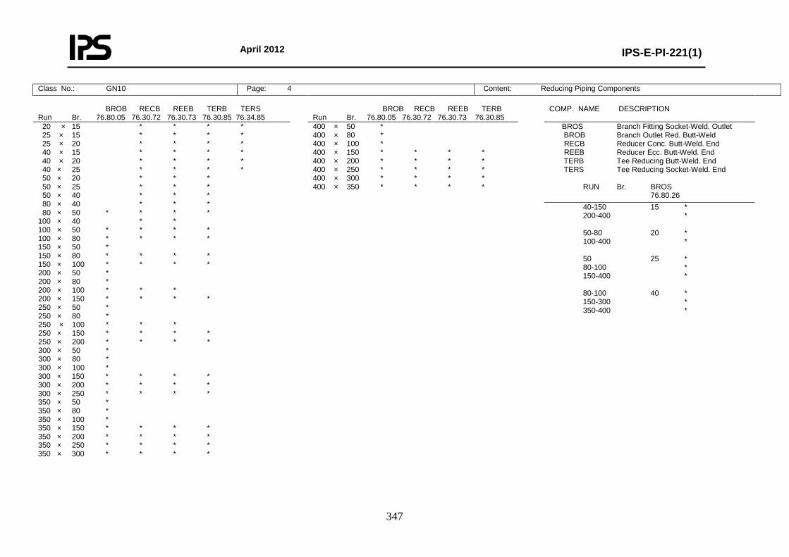
April 2012
IPS-E-PI-221(1)
347
Class No.: GN10 Page: 4 Content: Reducing Piping Components BROB RECB REEB TERB TERS Run Br. 76.80.05 76.30.72 76.30.73 76.30.85 76.34.85
BROB RECB REEB TERB Run Br. 76.80.05 76.30.72 76.30.73 76.30.85
COMP. NAME DESCRIPTION
20 × 15 * * * * 25 × 15 * * * * 25 × 20 * * * * 40 × 15 * * * * 40 × 20 * * * * 40 × 25 * * * * 50 × 20 * * * 50 × 25 * * * 50 × 40 * * * 80 × 40 * * * 80 × 50 * * * * 100 × 40 * * 100 × 50 * * * * 100 × 80 * * * * 150 × 50 * 150 × 80 * * * * 150 × 100 * * * * 200 × 50 * 200 × 80 * 200 × 100 * * * 200 × 150 * * * * 250 × 50 * 250 × 80 * 250 × 100 * * * 250 × 150 * * * * 250 × 200 * * * * 300 × 50 * 300 × 80 * 300 × 100 * 300 × 150 * * * * 300 × 200 * * * * 300 × 250 * * * * 350 × 50 * 350 × 80 * 350 × 100 * 350 × 150 * * * * 350 × 200 * * * * 350 × 250 * * * * 350 × 300 * * * *
400 × 50 * 400 × 80 * 400 × 100 * 400 × 150 * * * * 400 × 200 * * * * 400 × 250 * * * * 400 × 300 * * * * 400 × 350 * * * *
BROS Branch Fitting Socket-Weld. Outlet BROB Branch Outlet Red. Butt-Weld RECB Reducer Conc. Butt-Weld. End REEB Reducer Ecc. Butt-Weld. End TERB Tee Reducing Butt-Weld. End TERS Tee Reducing Socket-Weld. End RUN Br. BROS 76.80.26 40-150 15 * 200-400 * 50-80 20 * 100-400 * 50 25 * 80-100 * 150-400 * 80-100 40 * 150-300 * 350-400 *
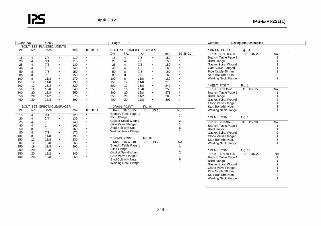
April 2012
IPS-E-PI-221(1)
348
Class No.: GN10 Page: 5 Content: Bolting and Assemblies BOLT SET FLANGED JOINTS DN No. Inch mm 81.38.61
BOLT SET ORIFICE FLANGES DN No. Inch mm 81.38.61
* DRAIN POINT Fig. 0J
Run DN 50-400 Br DN 20 No. Branch: Table Page 1 1 Blind Flange 1 Gasket Spiral Wound 2 Gate Valve Flanged 1 Pipe Nipple 50 mm 1 Stud Bolt with Nuts 8 Welding Neck Flange 1 * VENT POINT Fig. 1I
15 4 3/4 × 110 * 20 4 3/4 × 110 * 25 4 7/8 × 130 * 40 4 1 × 140 * 50 8 7/8 × 150 * 80 8 7/8 × 150 * 100 8 11/8 × 170 * 150 12 11/8 × 190 * 200 12 13/8 × 220 * 250 16 13/8 × 240 * 300 20 13/8 × 250 * 350 20 11/2 × 275 * 400 20 15/8 × 290 * BOLT SET SPECTACLE/SPACER DN No. Inch mm 81.38.61
15 4 7/8 × 150 * 20 4 7/8 × 150 * 25 4 7/8 × 150 * 40 4 1 × 160 * 50 8 7/8 × 160 * 80 8 7/8 × 160 * 100 8 11/8 × 180 * 150 12 11/8 × 210 * 200 12 13/8 × 240 * 250 16 13/8 × 250 * 300 20 13/8 × 275 * 350 20 11/2 × 300 * 400 20 15/8 × 305 * * DRAIN POINT Fig. 0I
Run DN 15-25 Br DN 15 No. Branch: Table Page 1 1 Blind Flange 1 Gasket Spiral Wound 2 Globe Valve Flanged 1 Stud Bolt with Nuts 8 Welding Neck Flange 1 * VENT POINT Fig. 1I
Run DN 15-25 Br DN 15 No. Branch: Table Page 1 1 Blind Flange 1 Gasket Spiral Wound 2 Gate Valve Flanged 1 Stud Bolt with Nuts 8 Welding Neck Flange 1 * DRAIN POINT Fig. 0I
15 4 3/4 × 120 * 20 4 3/4 × 130 * 25 4 7/8 × 140 * 40 4 1 × 160 * 50 8 7/8 × 160 * 80 8 7/8 × 170 * 100 8 11/8 × 195 * 150 12 11/8 × 230 * 200 12 13/8 × 265 * 250 16 13/8 × 290 * 300 20 13/8 × 310 * 350 20 11/2 × 345 * 400 20 15/8 × 360 *
Run DN 40-40 Br DN 20 No. Branch: Table Page 1 1 Blind Flange 1 Gasket Spiral Wound 2 Globe Valve Flanged 1 Stud Bolt with Nuts 8 Welding Neck Flange 1 * VENT POINT Fig. 1J
Run DN 40-40 Br DN 20 No. Branch: Table Page 1 1 Blind Flange 1 Gasket Spiral Wound 2 Gate Valve Flanged 1 Stud Bolt with Nuts 8 Welding Neck Flange 1
Run DN 50-400 Br DN 20 No. Branch: Table Page 1 1 Blind Flange 1 Gasket Spiral Wound 2 Globe Valve Flanged 1 Pipe Nipple 50 mm 1 Stud Bolt with Nuts 8 Welding Neck Flange 1
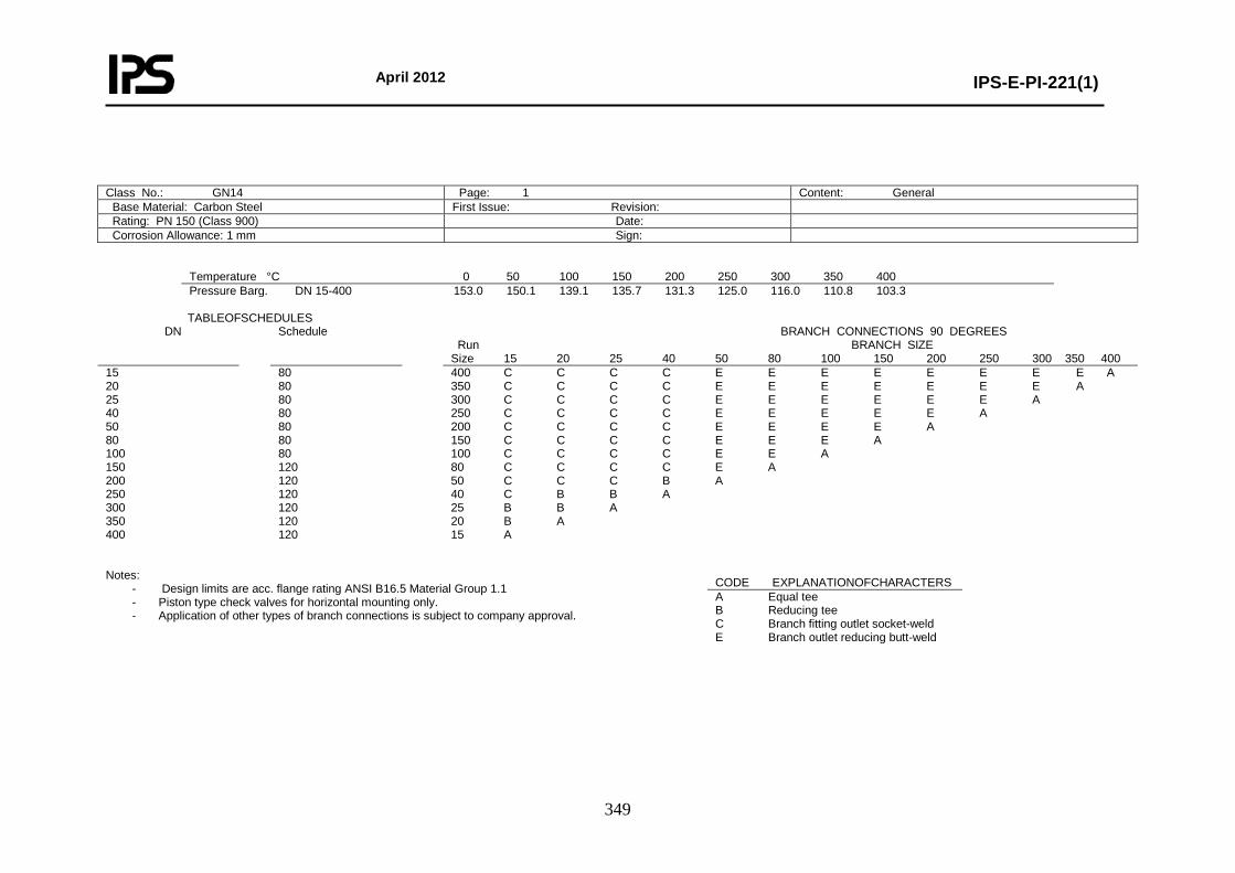
April 2012
IPS-E-PI-221(1)
349
Class No.: GN14 Page: 1 Content: General Base Material: Carbon Steel First Issue: Revision: Rating: PN 150 (Class 900) Date: Corrosion Allowance: 1 mm Sign:
Temperature °C 0 50 100 150 200 250 300 350 400 Pressure Barg. DN 15-400 153.0 150.1 139.1 135.7 131.3 125.0 116.0 110.8 103.3
TABLEOFSCHEDULES DN Schedule BRANCH CONNECTIONS 90 DEGREES
Run BRANCH SIZE Size 15 20 25 40 50 80 100 150 200 250 300 350 400
15 20 25 40 50 80 100 150 200 250 300 350 400
80 80 80 80 80 80 80 120 120 120 120 120 120
400 C C C C E E E E E E E E A 350 C C C C E E E E E E E A 300 C C C C E E E E E E A 250 C C C C E E E E E A 200 C C C C E E E E A 150 C C C C E E E A 100 C C C C E E A 80 C C C C E A 50 C C C B A 40 C B B A 25 B B A 20 B A 15 A
Notes:
- Design limits are acc. flange rating ANSI B16.5 Material Group 1.1 - Piston type check valves for horizontal mounting only. - Application of other types of branch connections is subject to company approval.
CODE EXPLANATIONOFCHARACTERS A Equal tee B Reducing tee C Branch fitting outlet socket-weld E Branch outlet reducing butt-weld
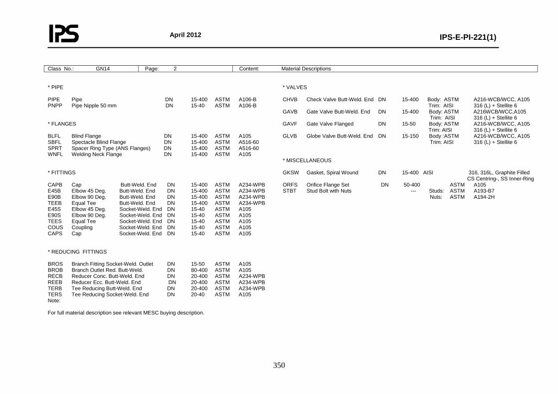
April 2012
IPS-E-PI-221(1)
350
Class No.: GN14 Page: 2 Content: Material Descriptions * PIPE PIPE Pipe DN 15-400 ASTM A106-B PNPP Pipe Nipple 50 mm DN 15-40 ASTM A106-B * FLANGES BLFL Blind Flange DN 15-400 ASTM A105 SBFL Spectacle Blind Flange DN 15-400 ASTM A516-60 SPRT Spacer Ring Type (ANS Flanges) DN 15-400 ASTM A516-60 WNFL Welding Neck Flange DN 15-400 ASTM A105 * FITTINGS CAPB Cap Butt-Weld. End DN 15-400 ASTM A234-WPB E45B Elbow 45 Deg. Butt-Weld. End DN 15-400 ASTM A234-WPB E90B Elbow 90 Deg. Butt-Weld. End DN 15-400 ASTM A234-WPB TEEB Equal Tee Butt-Weld. End DN 15-400 ASTM A234-WPB E45S Elbow 45 Deg. Socket-Weld. End DN 15-40 ASTM A105 E90S Elbow 90 Deg. Socket-Weld. End DN 15-40 ASTM A105 TEES Equal Tee Socket-Weld. End DN 15-40 ASTM A105 COUS Coupling Socket-Weld. End DN 15-40 ASTM A105 CAPS Cap Socket-Weld. End DN 15-40 ASTM A105 * REDUCING FITTINGS BROS Branch Fitting Socket-Weld. Outlet DN 15-50 ASTM A105 BROB Branch Outlet Red. Butt-Weld. DN 80-400 ASTM A105 RECB Reducer Conc. Butt-Weld. End DN 20-400 ASTM A234-WPB REEB Reducer Ecc. Butt-Weld. End DN 20-400 ASTM A234-WPB TERB Tee Reducing Butt-Weld. End DN 20-400 ASTM A234-WPB TERS Tee Reducing Socket-Weld. End DN 20-40 ASTM A105 Note: For full material description see relevant MESC buying description.
* VALVES CHVB Check Valve Butt-Weld. End DN 15-400 Body: ASTM A216-WCB/WCC, A105 Trim: AISI 316 (L) + Stellite 6 GAVB Gate Valve Butt-Weld. End DN 15-400 Body: ASTM A216WCB/WCC,A105 Trim: AISI 316 (L) + Stellite 6 GAVF Gate Valve Flanged DN 15-50 Body: ASTM A216-WCB/WCC, A105 Trim: AISI 316 (L) + Stellite 6 GLVB Globe Valve Butt-Weld. End DN 15-150 Body :ASTM A216-WCB/WCC, A105 Trim: AISI 316 (L) + Stellite 6 * MISCELLANEOUS GKSW Gasket, Spiral Wound DN 15-400 AISI 316, 316L, Graphite Filled CS Centring-, SS Inner-Ring ORFS Orifice Flange Set DN 50-400 ASTM A105 STBT Stud Bolt with Nuts --- Studs: ASTM A193-B7 Nuts: ASTM A194-2H
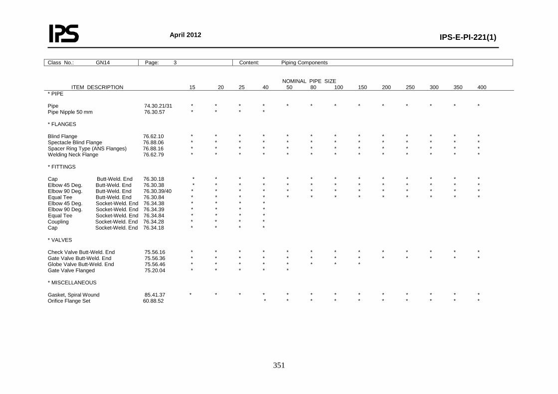
April 2012
IPS-E-PI-221(1)
351
Class No.: GN14 Page: 3 Content: Piping Components NOMINAL PIPE SIZE ITEM DESCRIPTION 15 20 25 40 50 80 100 150 200 250 300 350 400 * PIPE Pipe 74.30.21/31 * * * * * * * * * * * * * Pipe Nipple 50 mm 76.30.57 * * * * * FLANGES Blind Flange 76.62.10 * * * * * * * * * * * * * Spectacle Blind Flange 76.88.06 * * * * * * * * * * * * * Spacer Ring Type (ANS Flanges) 76.88.16 * * * * * * * * * * * * * Welding Neck Flange 76.62.79 * * * * * * * * * * * * * * FITTINGS Cap Butt-Weld. End 76.30.18 * * * * * * * * * * * * * Elbow 45 Deg. Butt-Weld. End 76.30.38 * * * * * * * * * * * * * Elbow 90 Deg. Butt-Weld. End 76.30.39/40 * * * * * * * * * * * * * Equal Tee Butt-Weld. End 76.30.84 * * * * * * * * * * * * * Elbow 45 Deg. Socket-Weld. End 76.34.38 * * * * Elbow 90 Deg. Socket-Weld. End 76.34.39 * * * * Equal Tee Socket-Weld. End 76.34.84 * * * * Coupling Socket-Weld. End 76.34.28 * * * * Cap Socket-Weld. End 76.34.18 * * * * * VALVES Check Valve Butt-Weld. End 75.56.16 * * * * * * * * * * * * * Gate Valve Butt-Weld. End 75.56.36 * * * * * * * * * * * * * Globe Valve Butt-Weld. End 75.56.46 * * * * * * * * Gate Valve Flanged 75.20.04 * * * * * * MISCELLANEOUS Gasket, Spiral Wound 85.41.37 * * * * * * * * * * * * * Orifice Flange Set 60.88.52 * * * * * * * * * *
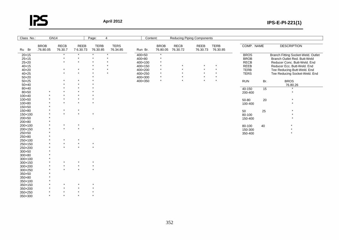
April 2012
IPS-E-PI-221(1)
352
Class No.: GN14 Page: 4 Content: Reducing Piping Components
BROB RECB REEB TERB TERS Ru Br .76.80.05 76.30.7 7 6.30.73 76.30.85 76.34.85
BROB RECB REEB TERB Run Br. 76.80.05 76.30.72 76.30.73 76.30.85
COMP. NAME DESCRIPTION
20×15 * * * * 25×15 * * * * 25×20 * * * * 40×15 * * 40×20 * * * * 40×25 * * * * 50×20 * 50×25 * * * 50×40 * * * 80×40 * * * 80×50 * * * * 100×40 * * * * 100×50 * * * * 100×80 * * * * 150×50 * 150×80 * * * 150×100 * * * * 200×50 * 200×80 * 200×100 * * * 200×150 * * * * 250×50 * 250×80 * 250×100 * * * 250×150 * * * * 250×200 * * * * 300×50 * 300×80 * 300×100 * 300×150 * * * * 300×200 * * * * 300×250 * * * * 350×50 * 350×80 * 350×100 * 350×150 * * * * 350×200 * * * * 350×250 * * * * 350×300 * * * *
400×50 * 400×80 * 400×100 * 400×150 * * * * 400×200 * * * * 400×250 * * * * 400×300 * * * * 400×350 * * * *
BROS Branch Fitting Socket-Weld. Outlet BROB Branch Outlet Red. Butt-Weld RECB Reducer Conc. Butt-Weld. End REEB Reducer Ecc. Butt-Weld. End TERB Tee Reducing Butt-Weld. End TERS Tee Reducing Socket-Weld. End
RUN Br. BROS 76.80.26
40-150 15 * 200-400 * 50-80 20 * 100-400 * 50 25 * 80-100 * 150-400 * 80-100 40 * 150-300 * 350-400 *
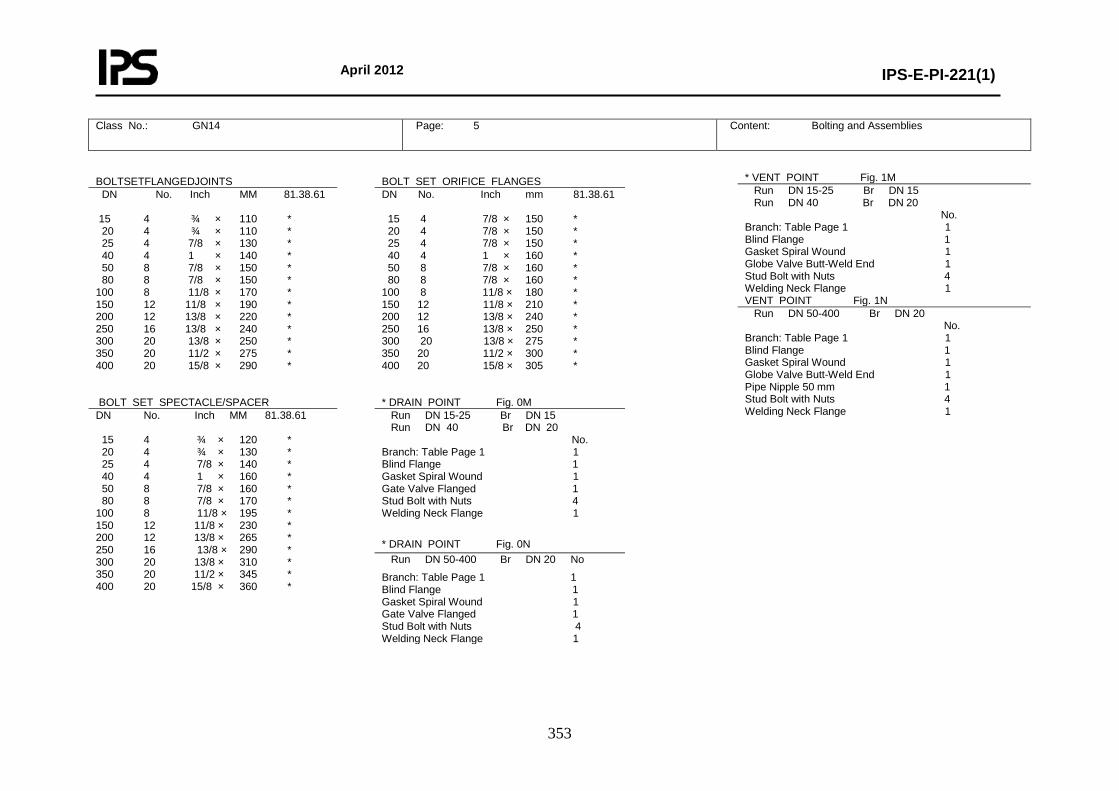
April 2012
IPS-E-PI-221(1)
353
Class No.: GN14 Page: 5
Content: Bolting and Assemblies
* VENT POINT Fig. 1M Run DN 15-25 Br DN 15 Run DN 40 Br DN 20 No. Branch: Table Page 1 1 Blind Flange 1 Gasket Spiral Wound 1 Globe Valve Butt-Weld End 1 Stud Bolt with Nuts 4 Welding Neck Flange 1 VENT POINT Fig. 1N Run DN 50-400 Br DN 20 No. Branch: Table Page 1 1 Blind Flange 1 Gasket Spiral Wound 1 Globe Valve Butt-Weld End 1 Pipe Nipple 50 mm 1 Stud Bolt with Nuts 4 Welding Neck Flange 1
BOLTSETFLANGEDJOINTS
BOLT SET ORIFICE FLANGES
DN No. Inch MM 81.38.61
DN No. Inch mm 81.38.61
15 4 ¾ × 110 * 20 4 ¾ × 110 * 25 4 7/8 × 130 * 40 4 1 × 140 * 50 8 7/8 × 150 * 80 8 7/8 × 150 * 100 8 11/8 × 170 * 150 12 11/8 × 190 * 200 12 13/8 × 220 * 250 16 13/8 × 240 * 300 20 13/8 × 250 * 350 20 11/2 × 275 * 400 20 15/8 × 290 *
15 4 7/8 × 150 * 20 4 7/8 × 150 * 25 4 7/8 × 150 * 40 4 1 × 160 * 50 8 7/8 × 160 * 80 8 7/8 × 160 * 100 8 11/8 × 180 * 150 12 11/8 × 210 * 200 12 13/8 × 240 * 250 16 13/8 × 250 * 300 20 13/8 × 275 * 350 20 11/2 × 300 * 400 20 15/8 × 305 *
BOLT SET SPECTACLE/SPACER
* DRAIN POINT Fig. 0M
DN No. Inch MM 81.38.61 Run DN 15-25 Br DN 15 Run DN 40 Br DN 20
15 4 ¾ × 120 * 20 4 ¾ × 130 * 25 4 7/8 × 140 * 40 4 1 × 160 * 50 8 7/8 × 160 * 80 8 7/8 × 170 * 100 8 11/8 × 195 * 150 12 11/8 × 230 * 200 12 13/8 × 265 * 250 16 13/8 × 290 * 300 20 13/8 × 310 * 350 20 11/2 × 345 * 400 20 15/8 × 360 *
No. Branch: Table Page 1 1 Blind Flange 1 Gasket Spiral Wound 1 Gate Valve Flanged 1 Stud Bolt with Nuts 4 Welding Neck Flange 1
* DRAIN POINT Fig. 0N Run DN 50-400 Br DN 20 No
Branch: Table Page 1 1 Blind Flange 1 Gasket Spiral Wound 1 Gate Valve Flanged 1 Stud Bolt with Nuts 4 Welding Neck Flange 1
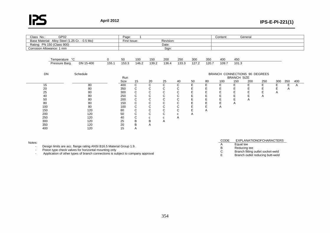
April 2012
IPS-E-PI-221(1)
354
Class No.: GP02 Page: 1 Content: General Base Material: Alloy Steel (1.25 Cr. - 0.5 Mo) First Issue: Revision: Rating: PN 150 (Class 900) Date: Corrosion Allowance: 1 mm Sign:
Temperature °C 0 50 100 150 200 250 300 350 400 450 Pressure Barg. DN 15-400 155.1 153.3 146.2 139.2 136.4 133.3 127.2 120.7 109.7 101.3
DN Schedule BRANCH CONNECTIONS 90 DEGREES
Run BRANCH SIZE Size 15 20 25 40 50 80 100 150 200 250 300 350 400
15 20 25 40 50 80
100 150 200 250 300 350 400
80 80 80 80 80 80 80
120 120 120 120 120 120
400 C C C C E E E E E E E E A 350 C C C C E E E E E E E A 300 C C C C E E E E E E A 250 C C C C E E E E E A 200 C C C C E E E E A 150 C C C C E E E A 100 C C C C E E A 80 C C C C E A 50 C C C c A 40 C c c A 25 B B A 20 B A 15 A
Notes:
- Design limits are acc. flange rating ANSI B16.5 Material Group 1.9. - Piston type check valves for horizontal mounting only - Application of other types of branch connections is subject to company approval
CODE EXPLANATIONOFCHARACTERS A Equal tee B Reducing tee C Branch fitting outlet socket-weld E Branch outlet reducing butt-weld
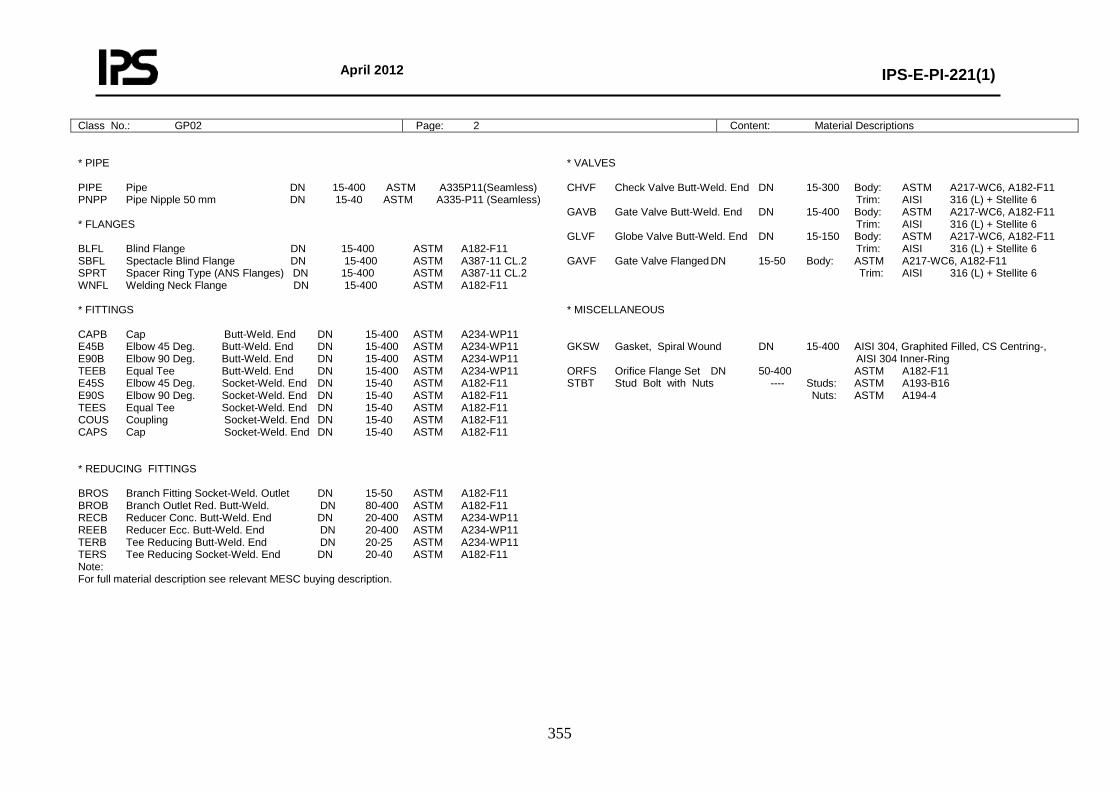
April 2012
IPS-E-PI-221(1)
355
Class No.: GP02 Page: 2 Content: Material Descriptions
* PIPE PIPE Pipe DN 15-400 ASTM A335P11(Seamless) PNPP Pipe Nipple 50 mm DN 15-40 ASTM A335-P11 (Seamless) * FLANGES BLFL Blind Flange DN 15-400 ASTM A182-F11 SBFL Spectacle Blind Flange DN 15-400 ASTM A387-11 CL.2 SPRT Spacer Ring Type (ANS Flanges) DN 15-400 ASTM A387-11 CL.2 WNFL Welding Neck Flange DN 15-400 ASTM A182-F11 * FITTINGS CAPB Cap Butt-Weld. End DN 15-400 ASTM A234-WP11 E45B Elbow 45 Deg. Butt-Weld. End DN 15-400 ASTM A234-WP11 E90B Elbow 90 Deg. Butt-Weld. End DN 15-400 ASTM A234-WP11 TEEB Equal Tee Butt-Weld. End DN 15-400 ASTM A234-WP11 E45S Elbow 45 Deg. Socket-Weld. End DN 15-40 ASTM A182-F11 E90S Elbow 90 Deg. Socket-Weld. End DN 15-40 ASTM A182-F11 TEES Equal Tee Socket-Weld. End DN 15-40 ASTM A182-F11 COUS Coupling Socket-Weld. End DN 15-40 ASTM A182-F11 CAPS Cap Socket-Weld. End DN 15-40 ASTM A182-F11 * REDUCING FITTINGS BROS Branch Fitting Socket-Weld. Outlet DN 15-50 ASTM A182-F11 BROB Branch Outlet Red. Butt-Weld. DN 80-400 ASTM A182-F11 RECB Reducer Conc. Butt-Weld. End DN 20-400 ASTM A234-WP11 REEB Reducer Ecc. Butt-Weld. End DN 20-400 ASTM A234-WP11 TERB Tee Reducing Butt-Weld. End DN 20-25 ASTM A234-WP11 TERS Tee Reducing Socket-Weld. End DN 20-40 ASTM A182-F11 Note: For full material description see relevant MESC buying description.
* VALVES CHVF Check Valve Butt-Weld. End DN 15-300 Body: ASTM A217-WC6, A182-F11 Trim: AISI 316 (L) + Stellite 6 GAVB Gate Valve Butt-Weld. End DN 15-400 Body: ASTM A217-WC6, A182-F11 Trim: AISI 316 (L) + Stellite 6 GLVF Globe Valve Butt-Weld. End DN 15-150 Body: ASTM A217-WC6, A182-F11 Trim: AISI 316 (L) + Stellite 6 GAVF Gate Valve Flanged DN 15-50 Body: ASTM A217-WC6, A182-F11 Trim: AISI 316 (L) + Stellite 6 * MISCELLANEOUS GKSW Gasket, Spiral Wound DN 15-400 AISI 304, Graphited Filled, CS Centring-, AISI 304 Inner-Ring ORFS Orifice Flange Set DN 50-400 ASTM A182-F11 STBT Stud Bolt with Nuts ---- Studs: ASTM A193-B16 Nuts: ASTM A194-4
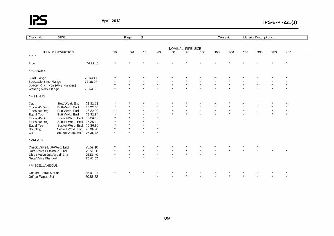
April 2012
IPS-E-PI-221(1)
356
Class No.: GP02 Page: 2 Content: Material Descriptions NOMINAL PIPE SIZE ITEM DESCRIPTION 15 20 25 40 50 80 100 150 200 250 300 350 400 * PIPE Pipe 74.33.11 * * * * * * * * * * * * * * FLANGES Blind Flange 76.64.10 * * * * * * * * * * * * * Spectacle Blind Flange 76.88.07 * * * * * * * * * * * * * Spacer Ring Type (ANS Flanges) * * * * * * * * * * * * * Welding Neck Flange 76.64.80 * * * * * * * * * * * * * * FITTINGS Cap Butt-Weld. End 76.32.18 * * * * * * * * * * * * * Elbow 45 Deg. Butt-Weld. End 76.32.38 * * * * * * * * * * * * * Elbow 90 Deg. Butt-Weld. End 76.32.39 * * * * * * * * * * * * * Equal Tee Butt-Weld. End 76.32.84 * * * * * * * * * * * * * Elbow 45 Deg. Socket-Weld. End 76.36.38 * * * * Elbow 90 Deg. Socket-Weld. End 76.36.39 * * * * Equal Tee Socket-Weld. End 76.36.80 * * * * Coupling Socket-Weld. End 76.36.28 * * * * Cap Socket-Weld. End 76.36.18 * * * * * VALVES Check Valve Butt-Weld. End 75.59.10 * * * * * * * * * * * Gate Valve Butt-Weld. End 75.59.30 * * * * * * * * * * * * * Globe Valve Butt-Weld. End 75.59.40 * * * * * * * * Gate Valve Flanged 75.41.33 * * * * * * MISCELLANEOUS Gasket, Spiral Wound 85.41.31 * * * * * * * * * * * * * Orifice Flange Set 60.88.52 * * * * * * * * * *
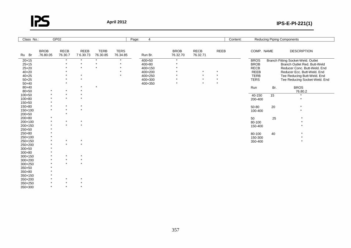
April 2012
IPS-E-PI-221(1)
357
Class No.: GP02 Page: 4 Content: Reducing Piping Components
BROB RECB REEB TERB TERS Ru Br .76.80.05 76.30.7 7 6.30.73 76.30.85 76.34.85
BROB RECB REEB Run Br. 76.32.70 76.32.71
COMP. NAME DESCRIPTION
20×15 * * * * 25×15 * * * * 25×20 * * * * 40×20 * * 40×25 * * * 50×25 * * 50×40 * 80×40 * * 80×50 * * * 100×50 * * * 100×80 * * * 150×50 * 150×80 * * * 150×100 * * * 200×50 * 200×80 * 200×100 * * * 200×150 * * * 250×50 * 250×80 * 250×100 * 250×150 * * * 250×200 * * * 300×50 * 300×80 * 300×150 * * * 300×200 * * * 300×250 * * * 350×50 * 350×80 * 350×150 * 350×200 * * * 350×250 * * * 350×300 * * *
400×50 * 400×80 * 400×150 * 400×200 * * * 400×250 * * * 400×300 * * * 400×350 * * *
BROS Branch Fitting Socket-Weld. Outlet BROB Branch Outlet Red. Butt-Weld RECB Reducer Conc. Butt-Weld. End REEB Reducer Ecc. Butt-Weld. End TERB Tee Reducing Butt-Weld. End TERS Tee Reducing Socket-Weld. End
Run Br. BROS 76.80.2
40-150 15 * 200-400 * 50-80 20 * 100-400 * 50 25 * 80-100 * 150-400 * 80-100 40 * 150-300 * 350-400 *
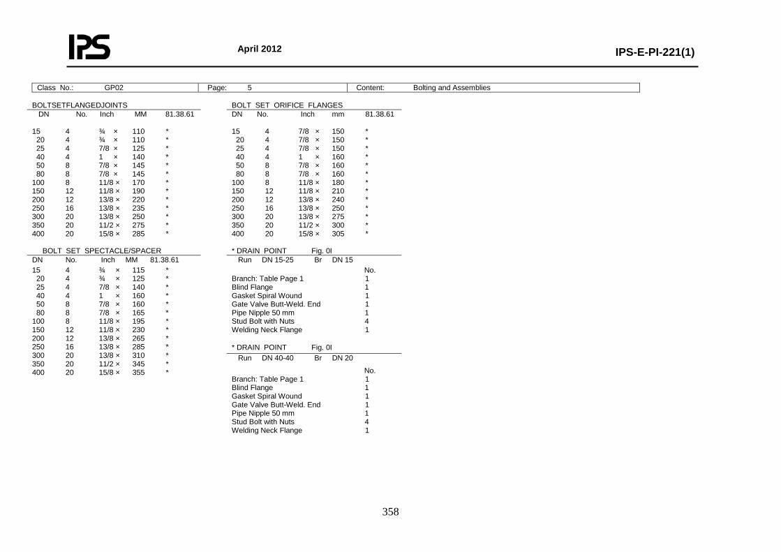
April 2012
IPS-E-PI-221(1)
358
Class No.: GP02 Page: 5 Content: Bolting and Assemblies
BOLTSETFLANGEDJOINTS BOLT SET ORIFICE FLANGES DN No. Inch MM 81.38.61
DN No. Inch mm 81.38.61
15 4 ¾ × 110 * 20 4 ¾ × 110 * 25 4 7/8 × 125 * 40 4 1 × 140 * 50 8 7/8 × 145 * 80 8 7/8 × 145 * 100 8 11/8 × 170 * 150 12 11/8 × 190 * 200 12 13/8 × 220 * 250 16 13/8 × 235 * 300 20 13/8 × 250 * 350 20 11/2 × 275 * 400 20 15/8 × 285 *
15 4 7/8 × 150 * 20 4 7/8 × 150 * 25 4 7/8 × 150 * 40 4 1 × 160 * 50 8 7/8 × 160 * 80 8 7/8 × 160 * 100 8 11/8 × 180 * 150 12 11/8 × 210 * 200 12 13/8 × 240 * 250 16 13/8 × 250 * 300 20 13/8 × 275 * 350 20 11/2 × 300 * 400 20 15/8 × 305 *
BOLT SET SPECTACLE/SPACER * DRAIN POINT Fig. 0I DN No. Inch MM 81.38.61 Run DN 15-25 Br DN 15 15 4 ¾ × 115 * 20 4 ¾ × 125 * 25 4 7/8 × 140 * 40 4 1 × 160 * 50 8 7/8 × 160 * 80 8 7/8 × 165 * 100 8 11/8 × 195 * 150 12 11/8 × 230 * 200 12 13/8 × 265 * 250 16 13/8 × 285 * 300 20 13/8 × 310 * 350 20 11/2 × 345 * 400 20 15/8 × 355 *
No. Branch: Table Page 1 1 Blind Flange 1 Gasket Spiral Wound 1 Gate Valve Butt-Weld. End 1 Pipe Nipple 50 mm 1 Stud Bolt with Nuts 4 Welding Neck Flange 1 * DRAIN POINT Fig. 0I Run DN 40-40 Br DN 20
No. Branch: Table Page 1 1 Blind Flange 1 Gasket Spiral Wound 1 Gate Valve Butt-Weld. End 1 Pipe Nipple 50 mm 1 Stud Bolt with Nuts 4 Welding Neck Flange 1
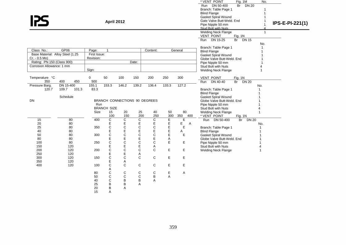
April 2012
IPS-E-PI-221(1)
359
Class No.: GP06 Page: 1 Content: General Base Material: Alloy Steel (1.25 Cr. - 0.5 Mo)
First Issue: Revision:
Rating: PN 150 (Class 900) Date: Corrosion Allowance: 1 mm
Sign:
Temperature °C 0 50 100 150 200 250 300 350 400 450 500 Pressure Barg. DN 15-400 155.1 153.3 146.2 139.2 136.4 133.3 127.2 120.7 109.7 101.3 83.3 DN
Schedule BRANCH CONNECTIONS 90 DEGREES Run BRANCH SIZE Size 15 20 25 40 50 80 100 150 200 250 300 350 400
15 20 25 40 50 80
100 150 200 250 300 350 400
80 80 80 80 80 80 80
120 120 120 120 120 120
400 C C C C E E E E E E E E A 350 C C C C E E E E E E E A 300 C C C C E E E E E E A 250 C C C C E E E E E A 200 C C C C E E E E A 150 C C C C E E E A 100 C C C C E E A 80 C C C C E A 50 C C C B A 40 C B B A 25 B B A 20 B A 15 A
* VENT POINT Fig. 1M No. Run DN 50-400 Br DN 20 Branch: Table Page 1 1 Blind Flange 1 Gasket Spiral Wound 1 Gate Valve Butt-Weld. End 1 Pipe Nipple 50 mm 1 Stud Bolt with Nuts 4 Welding Neck Flange 1 VENT POINT Fig. 1N Run DN 15-25 Br DN 15 No. Branch: Table Page 1 1 Blind Flange 1 Gasket Spiral Wound 1 Globe Valve Butt-Weld. End 1 Pipe Nipple 50 mm 1 Stud Bolt with Nuts 4 Welding Neck Flange 1 VENT POINT Fig. 1N Run DN 40-40 Br DN 20 No. Branch: Table Page 1 1 Blind Flange 1 Gasket Spiral Wound 1 Globe Valve Butt-Weld. End 1 Pipe Nipple 50 mm 1 Stud Bolt with Nuts 4 Welding Neck Flange 1 * VENT POINT Fig. 1N Run DN 50-400 Br DN 20 No. Branch: Table Page 1 1 Blind Flange 1 Gasket Spiral Wound 1 Globe Valve Butt-Weld. End 1 Pipe Nipple 50 mm 1 Stud Bolt with Nuts 4 Welding Neck Flange 1
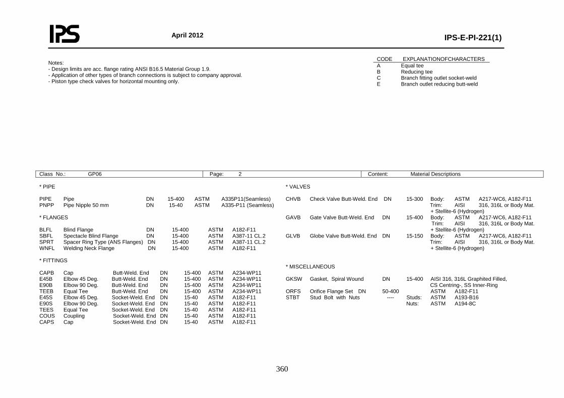
April 2012
IPS-E-PI-221(1)
360
Notes: - Design limits are acc. flange rating ANSI B16.5 Material Group 1.9. - Application of other types of branch connections is subject to company approval. - Piston type check valves for horizontal mounting only.
Class No.: GP06 Page: 2 Content: Material Descriptions
* PIPE PIPE Pipe DN 15-400 ASTM A335P11(Seamless) PNPP Pipe Nipple 50 mm DN 15-40 ASTM A335-P11 (Seamless) * FLANGES BLFL Blind Flange DN 15-400 ASTM A182-F11 SBFL Spectacle Blind Flange DN 15-400 ASTM A387-11 CL.2 SPRT Spacer Ring Type (ANS Flanges) DN 15-400 ASTM A387-11 CL.2 WNFL Welding Neck Flange DN 15-400 ASTM A182-F11 * FITTINGS CAPB Cap Butt-Weld. End DN 15-400 ASTM A234-WP11 E45B Elbow 45 Deg. Butt-Weld. End DN 15-400 ASTM A234-WP11 E90B Elbow 90 Deg. Butt-Weld. End DN 15-400 ASTM A234-WP11 TEEB Equal Tee Butt-Weld. End DN 15-400 ASTM A234-WP11 E45S Elbow 45 Deg. Socket-Weld. End DN 15-40 ASTM A182-F11 E90S Elbow 90 Deg. Socket-Weld. End DN 15-40 ASTM A182-F11 TEES Equal Tee Socket-Weld. End DN 15-40 ASTM A182-F11 COUS Coupling Socket-Weld. End DN 15-40 ASTM A182-F11 CAPS Cap Socket-Weld. End DN 15-40 ASTM A182-F11
* VALVES CHVB Check Valve Butt-Weld. End DN 15-300 Body: ASTM A217-WC6, A182-F11 Trim: AISI 316, 316L or Body Mat. + Stellite-6 (Hydrogen) GAVB Gate Valve Butt-Weld. End DN 15-400 Body: ASTM A217-WC6, A182-F11 Trim: AISI 316, 316L or Body Mat. + Stellite-6 (Hydrogen) GLVB Globe Valve Butt-Weld. End DN 15-150 Body: ASTM A217-WC6, A182-F11 Trim: AISI 316, 316L or Body Mat. + Stellite-6 (Hydrogen) * MISCELLANEOUS GKSW Gasket, Spiral Wound DN 15-400 AISI 316, 316L Graphited Filled, CS Centring-, SS Inner-Ring ORFS Orifice Flange Set DN 50-400 ASTM A182-F11 STBT Stud Bolt with Nuts ---- Studs: ASTM A193-B16 Nuts: ASTM A194-8C
CODE EXPLANATIONOFCHARACTERS A Equal tee B Reducing tee C Branch fitting outlet socket-weld E Branch outlet reducing butt-weld
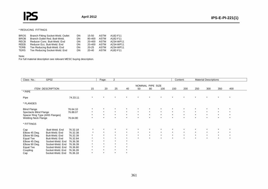
April 2012
IPS-E-PI-221(1)
361
* REDUCING FITTINGS BROS Branch Fitting Socket-Weld. Outlet DN 15-50 ASTM A182-F11 BROB Branch Outlet Red. Butt-Weld. DN 80-400 ASTM A182-F11 RECB Reducer Conc. Butt-Weld. End DN 20-400 ASTM A234-WP11 REEB Reducer Ecc. Butt-Weld. End DN 20-400 ASTM A234-WP11 TERB Tee Reducing Butt-Weld. End DN 20-25 ASTM A234-WP11 TERS Tee Reducing Socket-Weld. End DN 20-40 ASTM A182-F11 Note: For full material description see relevant MESC buying description.
Class No.: GP02 Page: 2 Content: Material Descriptions NOMINAL PIPE SIZE ITEM DESCRIPTION 15 20 25 40 50 80 100 150 200 250 300 350 400 * PIPE Pipe 74.33.11 * * * * * * * * * * * * * * FLANGES Blind Flange 76.64.10 * * * * * * * * * * * * * Spectacle Blind Flange 76.88.07 * * * * * * * * * * * * * Spacer Ring Type (ANS Flanges) * * * * * * * * * * * * * Welding Neck Flange 76.64.80 * * * * * * * * * * * * * * FITTINGS Cap Butt-Weld. End 76.32.18 * * * * * * * * * * * * * Elbow 45 Deg. Butt-Weld. End 76.32.38 * * * * * * * * * * * * * Elbow 90 Deg. Butt-Weld. End 76.32.39 * * * * * * * * * * * * * Equal Tee Butt-Weld. End 76.32.84 * * * * * * * * * * * * * Elbow 45 Deg. Socket-Weld. End 76.36.38 * * * * Elbow 90 Deg. Socket-Weld. End 76.36.39 * * * * Equal Tee Socket-Weld. End 76.36.80 * * * * Coupling Socket-Weld. End 76.36.28 * * * * Cap Socket-Weld. End 76.36.18 * * * *
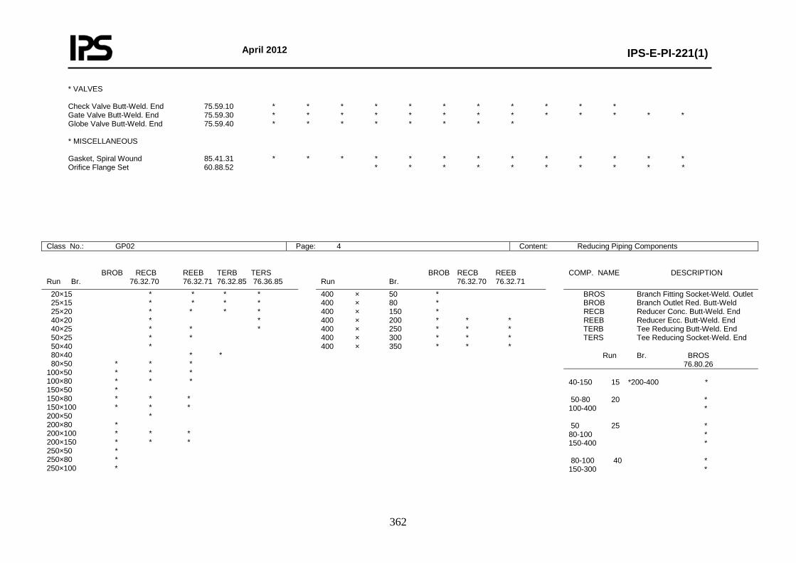
April 2012
IPS-E-PI-221(1)
362
* VALVES Check Valve Butt-Weld. End 75.59.10 * * * * * * * * * * * Gate Valve Butt-Weld. End 75.59.30 * * * * * * * * * * * * * Globe Valve Butt-Weld. End 75.59.40 * * * * * * * * * MISCELLANEOUS Gasket, Spiral Wound 85.41.31 * * * * * * * * * * * * * Orifice Flange Set 60.88.52 * * * * * * * * * *
Class No.: GP02 Page: 4 Content: Reducing Piping Components
BROB RECB REEB TERB TERS Run Br. 76.32.70 76.32.71 76.32.85 76.36.85
BROB RECB REEB Run Br. 76.32.70 76.32.71
COMP. NAME DESCRIPTION
20×15 * * * * 25×15 * * * * 25×20 * * * * 40×20 * * 40×25 * * * 50×25 * * 50×40 * 80×40 * * 80×50 * * * 100×50 * * * 100×80 * * * 150×50 * 150×80 * * * 150×100 * * * 200×50 * 200×80 * 200×100 * * * 200×150 * * * 250×50 * 250×80 * 250×100 *
400 × 50 * 400 × 80 * 400 × 150 * 400 × 200 * * * 400 × 250 * * * 400 × 300 * * * 400 × 350 * * *
BROS Branch Fitting Socket-Weld. Outlet BROB Branch Outlet Red. Butt-Weld RECB Reducer Conc. Butt-Weld. End REEB Reducer Ecc. Butt-Weld. End TERB Tee Reducing Butt-Weld. End TERS Tee Reducing Socket-Weld. End
Run Br. BROS 76.80.26
40-150 15 *200-400 * 50-80 20 * 100-400 * 50 25 * 80-100 * 150-400 * 80-100 40 * 150-300 *
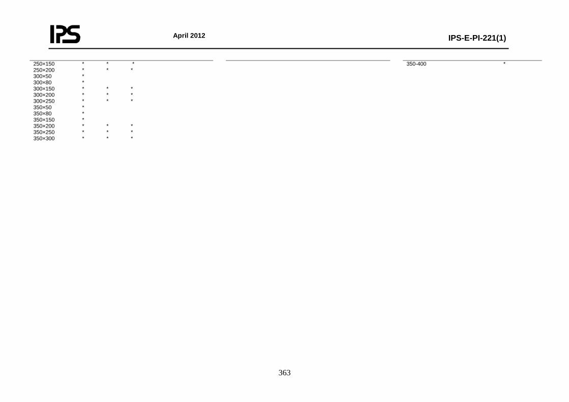
April 2012
IPS-E-PI-221(1)
363
250×150 * * * 250×200 * * * 300×50 * 300×80 * 300×150 * * * 300×200 * * * 300×250 * * * 350×50 * 350×80 * 350×150 * 350×200 * * * 350×250 * * * 350×300 * * *
350-400 *
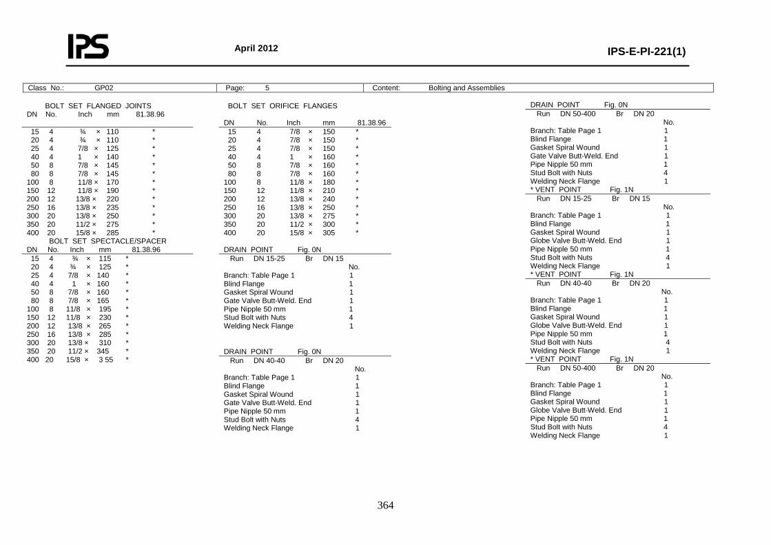
April 2012
IPS-E-PI-221(1)
364
Class No.: GP02 Page: 5 Content: Bolting and Assemblies
BOLT SET FLANGED JOINTS DN No. Inch mm 81.38.96
BOLT SET ORIFICE FLANGES DN No. Inch mm 81.38.96
15 4 ¾ × 110 * 20 4 ¾ × 110 * 25 4 7/8 × 125 * 40 4 1 × 140 * 50 8 7/8 × 145 * 80 8 7/8 × 145 * 100 8 11/8 × 170 * 150 12 11/8 × 190 * 200 12 13/8 × 220 * 250 16 13/8 × 235 * 300 20 13/8 × 250 * 350 20 11/2 × 275 * 400 20 15/8 × 285 *
15 4 7/8 × 150 * 20 4 7/8 × 150 * 25 4 7/8 × 150 * 40 4 1 × 160 * 50 8 7/8 × 160 * 80 8 7/8 × 160 * 100 8 11/8 × 180 * 150 12 11/8 × 210 * 200 12 13/8 × 240 * 250 16 13/8 × 250 * 300 20 13/8 × 275 * 350 20 11/2 × 300 * 400 20 15/8 × 305 *
BOLT SET SPECTACLE/SPACER DN No. Inch mm 81.38.96
DRAIN POINT Fig. 0N
15 4 ¾ × 115 * 20 4 ¾ × 125 * 25 4 7/8 × 140 * 40 4 1 × 160 * 50 8 7/8 × 160 * 80 8 7/8 × 165 * 100 8 11/8 × 195 * 150 12 11/8 × 230 * 200 12 13/8 × 265 * 250 16 13/8 × 285 * 300 20 13/8 × 310 * 350 20 11/2 × 345 * 400 20 15/8 × 3 55 *
Run DN 15-25 Br DN 15 No. Branch: Table Page 1 1 Blind Flange 1 Gasket Spiral Wound 1 Gate Valve Butt-Weld. End 1 Pipe Nipple 50 mm 1 Stud Bolt with Nuts 4 Welding Neck Flange 1 DRAIN POINT Fig. 0N Run DN 40-40 Br DN 20 No. Branch: Table Page 1 1 Blind Flange 1 Gasket Spiral Wound 1 Gate Valve Butt-Weld. End 1 Pipe Nipple 50 mm 1 Stud Bolt with Nuts 4 Welding Neck Flange 1
DRAIN POINT Fig. 0N Run DN 50-400 Br DN 20 No. Branch: Table Page 1 1 Blind Flange 1 Gasket Spiral Wound 1 Gate Valve Butt-Weld. End 1 Pipe Nipple 50 mm 1 Stud Bolt with Nuts 4 Welding Neck Flange 1 * VENT POINT Fig. 1N Run DN 15-25 Br DN 15 No. Branch: Table Page 1 1 Blind Flange 1 Gasket Spiral Wound 1 Globe Valve Butt-Weld. End 1 Pipe Nipple 50 mm 1 Stud Bolt with Nuts 4 Welding Neck Flange 1 * VENT POINT Fig. 1N Run DN 40-40 Br DN 20 No. Branch: Table Page 1 1 Blind Flange 1 Gasket Spiral Wound 1 Globe Valve Butt-Weld. End 1 Pipe Nipple 50 mm 1 Stud Bolt with Nuts 4 Welding Neck Flange 1 * VENT POINT Fig. 1N Run DN 50-400 Br DN 20 No. Branch: Table Page 1 1 Blind Flange 1 Gasket Spiral Wound 1 Globe Valve Butt-Weld. End 1 Pipe Nipple 50 mm 1 Stud Bolt with Nuts 4 Welding Neck Flange 1
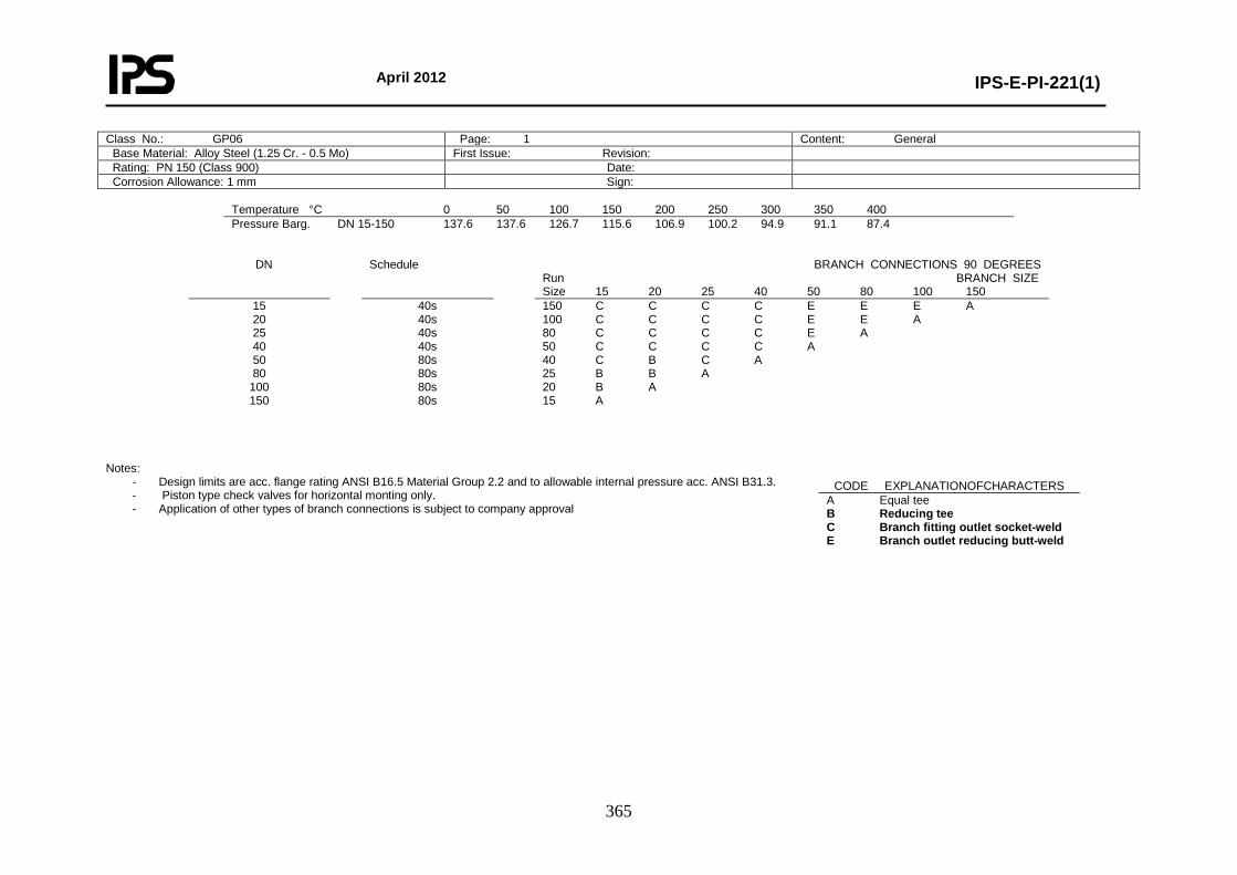
April 2012
IPS-E-PI-221(1)
365
Class No.: GP06 Page: 1 Content: General Base Material: Alloy Steel (1.25 Cr. - 0.5 Mo) First Issue: Revision: Rating: PN 150 (Class 900) Date: Corrosion Allowance: 1 mm Sign:
Temperature °C 0 50 100 150 200 250 300 350 400 Pressure Barg. DN 15-150 137.6 137.6 126.7 115.6 106.9 100.2 94.9 91.1 87.4
DN Schedule BRANCH CONNECTIONS 90 DEGREES Run BRANCH SIZE Size 15 20 25 40 50 80 100 150
15 20 25 40 50 80
100 150
40s 40s 40s 40s 80s 80s 80s 80s
150 C C C C E E E A 100 C C C C E E A 80 C C C C E A 50 C C C C A 40 C B C A 25 B B A 20 B A 15 A
Notes:
- Design limits are acc. flange rating ANSI B16.5 Material Group 2.2 and to allowable internal pressure acc. ANSI B31.3. - Piston type check valves for horizontal monting only. - Application of other types of branch connections is subject to company approval
CODE EXPLANATIONOFCHARACTERS A Equal tee B Reducing tee C Branch fitting outlet socket-weld E Branch outlet reducing butt-weld
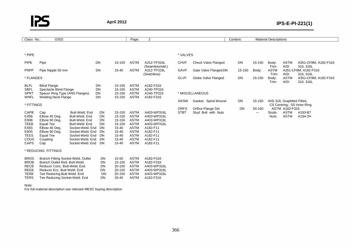
April 2012
IPS-E-PI-221(1)
366
Class No.: GS02 Page: 2 Content: Material Descriptions
* PIPE PIPE Pipe DN 15-150 ASTM A312-TP316L (Seamless/wld.) PNPP Pipe Nipple 50 mm DN 15-40 ASTM A312-TP316L (Seamless) * FLANGES BLFL Blind Flange DN 15-150 ASTM A182-F316 SBFL Spectacle Blind Flange DN 15-150 ASTM A240-TP316 SPRT Spacer Ring Type (ANS Flanges) DN 15-150 ASTM A240-TP316 WNFL Welding Neck Flange DN 15-150 ASTM A182-F316 * FITTINGS CAPB Cap Butt-Weld. End DN 15-150 ASTM A403-WP316L E45B Elbow 45 Deg. Butt-Weld. End DN 15-150 ASTM A403-WP316L E90B Elbow 90 Deg. Butt-Weld. End DN 15-150 ASTM A403-WP316L TEEB Equal Tee Butt-Weld. End DN 15-150 ASTM A403-WP316L E45S Elbow 45 Deg. Socket-Weld. End DN 15-40 ASTM A182-F11 E90S Elbow 90 Deg. Socket-Weld. End DN 15-40 ASTM A182-F11 TEES Equal Tee Socket-Weld. End DN 15-40 ASTM A182-F11 COUS Coupling Socket-Weld. End DN 15-40 ASTM A182-F11 CAPS Cap Socket-Weld. End DN 15-40 ASTM A182-F11 * REDUCING FITTINGS BROS Branch Fitting Socket-Weld. Outlet DN 15-50 ASTM A182-F316 BROB Branch Outlet Red. Butt-Weld. DN 15-150 ASTM A182-F316 RECB Reducer Conc. Butt-Weld. End DN 20-150 ASTM A403-WP316L REEB Reducer Ecc. Butt-Weld. End DN 20-150 ASTM A403-WP316L TERB Tee Reducing Butt-Weld. End DN 20-150 ASTM A403-WP316L TERS Tee Reducing Socket-Weld. End DN 20-40 ASTM A182-F316 Note: For full material description see relevant MESC buying description.
* VALVES CHVF Check Valve Flanged DN 15-150 Body: ASTM A351-CF8M, A182-F316 Trim: AISI 316, 316L GAVF Gate Valve Flanged DN 15-150 Body: ASTM A351-CF8M, A182-F316 Trim: AISI 316, 316L GLVF Globe Valve Flanged DN 15-150 Body: ASTM A351-CF8M, A182-F316 Trim: AISI 316, 316L * MISCELLANEOUS GKSW Gasket, Spiral Wound DN 15-150 AISI 316, Graphited Filled, CS Centring-, SS Inner-Ring ORFS Orifice Flange Set DN 50-150 ASTM A182-F316 STBT Stud Bolt with Nuts --- Studs: ASTM A193-B7 Nuts: ASTM A194-2H

April 2012
IPS-E-PI-221(1)
367
Class No.: GS02 Page: 3 Content: Piping Components NOMINAL PIPE SIZE ITEM DESCRIPTION 15 20 25 40 50 80 100 150 * PIPE Pipe 74.36.40 * * * * * * * * * FLANGES Blind Flange 76.65.11 * * * * * * * * Spectacle Blind Flange 76.88.07 * * * * * * * * Spacer Ring Type (ANS Flanges) * * * * * * * * Welding Neck Flange 76.65.80 * * * * * * * * * FITTINGS Cap Butt-Weld. End 76.32.18 * * * * * * * * Elbow 45 Deg. Butt-Weld. End 76.33.38 * * * * * * * * Elbow 90 Deg. Butt-Weld. End 76.33.40 * * * * * * * * Equal Tee Butt-Weld. End 76.33.84 * * * * * * * * Elbow 45 Deg. Socket-Weld. End 76.37.38 * * * * Elbow 90 Deg. Socket-Weld. End 76.37.39 * * * * Equal Tee Socket-Weld. End 76.37.80 * * * * Coupling Socket-Weld. End 76.37.28 * * * * Cap Socket-Weld. End 76.37.18 * * * * * VALVES Check Valve Flanged 75.40.11 * * * * * * * * Gate Valve Flanged 75.40.31 * * * * * * * * Globe Valve Flanged 75.40.41 * * * * * * * * * MISCELLANEOUS Gasket, Spiral Wound 85.41.37 * * * * * * * * Orifice Flange Set 60.88.52 * * * *
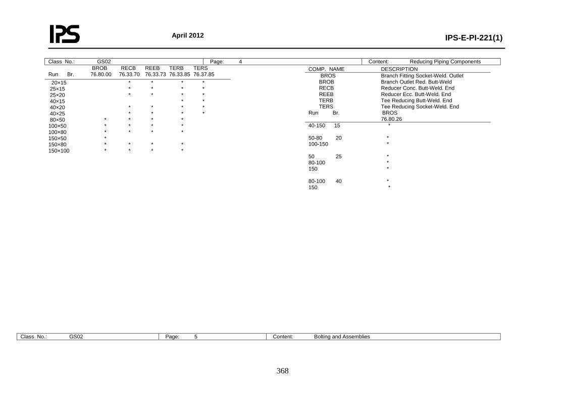
April 2012
IPS-E-PI-221(1)
368
BROB RECB REEB TERB TERS Run Br. 76.80.00 76.33.70 76.33.73 76.33.85 76.37.85 20×15 * * * * 25×15 * * * * 25×20 * * * * 40×15 * * 40×20 * * * * 40×25 * * * * 80×50 * * * * 100×50 * * * * 100×80 * * * * 150×50 * 150×80 * * * * 150×100 * * * *
Class No.: GS02 Page: 4 Content: Reducing Piping Components COMP. NAME DESCRIPTION BROS Branch Fitting Socket-Weld. Outlet BROB Branch Outlet Red. Butt-Weld RECB Reducer Conc. Butt-Weld. End REEB Reducer Ecc. Butt-Weld. End TERB Tee Reducing Butt-Weld. End TERS Tee Reducing Socket-Weld. End Run Br. BROS 76.80.26 40-150 15 * 50-80 20 * 100-150 * 50 25 * 80-100 * 150 * 80-100 40 * 150 *
Class No.: GS02 Page: 5 Content: Bolting and Assemblies
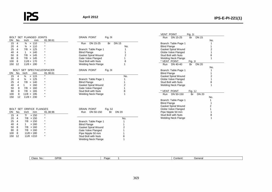
April 2012
IPS-E-PI-221(1)
369
Class No.: GP06 Page: 1 Content: General
BOLT SET FLANGED JOINTS DN No. Inch mm 81.38.61
DRAIN POINT Fig. 0I
15 4 ¾ × 110 * 20 4 ¾ × 110 * 25 4 7/8 × 125 * 40 4 1 × 140 * 50 8 7/8 × 145 * 80 8 7/8 × 145 * 100 8 11/8 × 170 * 150 12 11/8 × 190 *
Run DN 15-25 Br DN 15 No. Branch: Table Page 1 1 Blind Flange 1 Gasket Spiral Wound 2 Gate Valve Flanged 1 Stud Bolt with Nuts 8 Welding Neck Flange 1
BOLT SET SPECTACLE/SPACER DN No. Inch mm 81.38.61
DRAIN POINT Fig. 0I
15 4 ¾ × 115 * 20 4 ¾ × 125 * 25 4 7/8 × 140 * 40 4 1 × 160 * 50 8 7/8 × 160 * 80 8 7/8 × 165 * 100 8 11/8 × 195 * 150 12 11/8 × 230 *
No. Branch: Table Page 1 1 Blind Flange 1 Gasket Spiral Wound 2 Gate Valve Flanged 1 Stud Bolt with Nuts 8 Welding Neck Flange 1
BOLT SET ORIFICE FLANGES DN No. Inch mm 81.38.96
DRAIN POINT Fig. 0J Run DN 50-150 Br DN 20 15 4 7/ × 150 *
20 4 7/8 × 150 * 25 4 7/8 × 150 * 40 4 1 × 160 * 50 8 7/8 × 160 * 80 8 7/8 × 160 * 100 8 11/8 × 180 * 150 12 11/8 × 210 *
No. Branch: Table Page 1 1 Blind Flange 1 Gasket Spiral Wound 2 Gate Valve Flanged 1 Pipe Nipple 50 mm 1 Stud Bolt with Nuts 8 Welding Neck Flange 1
VENT POINT Fig. 1I Run DN 15-25 Br DN 15 No. Branch: Table Page 1 1 Blind Flange 1 Gasket Spiral Wound 2 Globe Valve Flanged 1 Stud Bolt with Nuts 8 Welding Neck Flange 1 * VENT POINT Fig. 1I Run DN 40-40 Br DN 20 No. Branch: Table Page 1 1 Blind Flange 1 Gasket Spiral Wound 2 Globe Valve Flanged 1 Stud Bolt with Nuts 8 Welding Neck Flange 1 * VENT POINT Fig. 1J Run DN 50-150 Br DN 20 No. Branch: Table Page 1 1 Blind Flange 1 Gasket Spiral Wound 2 Globe Valve Flanged 1 Pipe Nipple 50 mm 1 Stud Bolt with Nuts 8 Welding Neck Flange 1
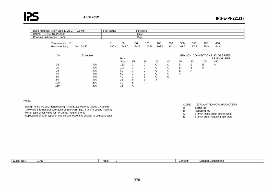
April 2012
IPS-E-PI-221(1)
370
Base Material: Alloy Steel (1.25 Cr. - 0.5 Mo) First Issue: Revision: Rating: PN 150 (Class 900) Date: Corrosion Allowance: 1 mm Sign:
Temperature °C 0 50 100 150 200 250 300 350 400 450 Pressure Barg. DN 15-150 146.4 142.0 124.5 112.5 103.2 96.1 91.5 87.9 85.8 84.6
DN Schedule BRANCH CONNECTIONS 90 DEGREES Run BRANCH SIZE Size 15 20 25 40 50 80 100 150
15 20 25 40 50 80
100 150
40s 40s 40s 40s 40s 40s 80s 80s
150 C C C C E E E A 100 C C C C E E A 80 C C C C E A 50 C C C C A 40 C B C A 25 B c A 20 B A 15 A
Notes:
- Design limits are acc. flange rating ANSI B16.5 Material Group 2.4 and to allowable internal pressure according to ANSI B31.3 and to bolting materia - Piston type check valve for horizontal mounting only - Application of other types of branch connections is subject to company appr
Class No.: GS06 Page: 2 Content: Material Descriptions
CODE EXPLANATION OFCHARACTERS A Equal tee B Reducing tee C Branch fitting outlet socket-weld E Branch outlet reducing butt-weld
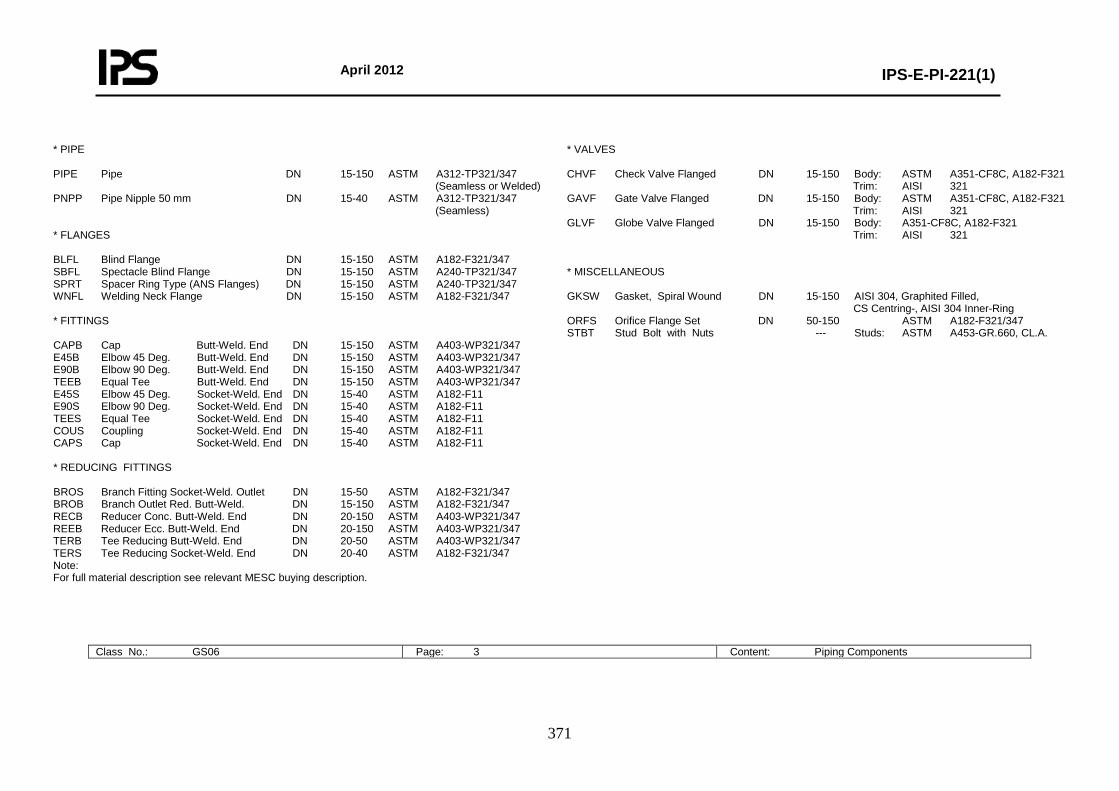
April 2012
IPS-E-PI-221(1)
371
* PIPE PIPE Pipe DN 15-150 ASTM A312-TP321/347 (Seamless or Welded) PNPP Pipe Nipple 50 mm DN 15-40 ASTM A312-TP321/347 (Seamless) * FLANGES BLFL Blind Flange DN 15-150 ASTM A182-F321/347 SBFL Spectacle Blind Flange DN 15-150 ASTM A240-TP321/347 SPRT Spacer Ring Type (ANS Flanges) DN 15-150 ASTM A240-TP321/347 WNFL Welding Neck Flange DN 15-150 ASTM A182-F321/347 * FITTINGS CAPB Cap Butt-Weld. End DN 15-150 ASTM A403-WP321/347 E45B Elbow 45 Deg. Butt-Weld. End DN 15-150 ASTM A403-WP321/347 E90B Elbow 90 Deg. Butt-Weld. End DN 15-150 ASTM A403-WP321/347 TEEB Equal Tee Butt-Weld. End DN 15-150 ASTM A403-WP321/347 E45S Elbow 45 Deg. Socket-Weld. End DN 15-40 ASTM A182-F11 E90S Elbow 90 Deg. Socket-Weld. End DN 15-40 ASTM A182-F11 TEES Equal Tee Socket-Weld. End DN 15-40 ASTM A182-F11 COUS Coupling Socket-Weld. End DN 15-40 ASTM A182-F11 CAPS Cap Socket-Weld. End DN 15-40 ASTM A182-F11 * REDUCING FITTINGS BROS Branch Fitting Socket-Weld. Outlet DN 15-50 ASTM A182-F321/347 BROB Branch Outlet Red. Butt-Weld. DN 15-150 ASTM A182-F321/347 RECB Reducer Conc. Butt-Weld. End DN 20-150 ASTM A403-WP321/347 REEB Reducer Ecc. Butt-Weld. End DN 20-150 ASTM A403-WP321/347 TERB Tee Reducing Butt-Weld. End DN 20-50 ASTM A403-WP321/347 TERS Tee Reducing Socket-Weld. End DN 20-40 ASTM A182-F321/347 Note: For full material description see relevant MESC buying description.
* VALVES CHVF Check Valve Flanged DN 15-150 Body: ASTM A351-CF8C, A182-F321 Trim: AISI 321 GAVF Gate Valve Flanged DN 15-150 Body: ASTM A351-CF8C, A182-F321 Trim: AISI 321 GLVF Globe Valve Flanged DN 15-150 Body: A351-CF8C, A182-F321 Trim: AISI 321 * MISCELLANEOUS GKSW Gasket, Spiral Wound DN 15-150 AISI 304, Graphited Filled, CS Centring-, AISI 304 Inner-Ring ORFS Orifice Flange Set DN 50-150 ASTM A182-F321/347 STBT Stud Bolt with Nuts --- Studs: ASTM A453-GR.660, CL.A.
Class No.: GS06 Page: 3 Content: Piping Components
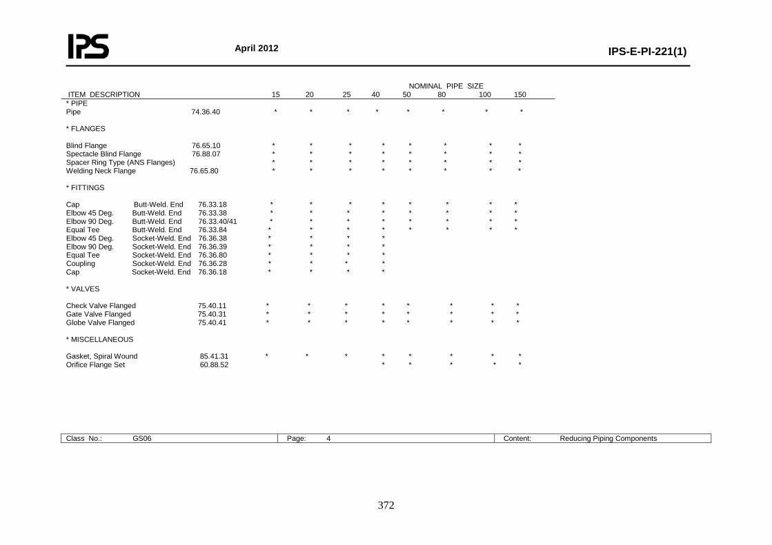
April 2012
IPS-E-PI-221(1)
372
NOMINAL PIPE SIZE ITEM DESCRIPTION 15 20 25 40 50 80 100 150 * PIPE Pipe 74.36.40 * * * * * * * * * FLANGES Blind Flange 76.65.10 * * * * * * * * Spectacle Blind Flange 76.88.07 * * * * * * * * Spacer Ring Type (ANS Flanges) * * * * * * * * Welding Neck Flange 76.65.80 * * * * * * * * * FITTINGS Cap Butt-Weld. End 76.33.18 * * * * * * * * Elbow 45 Deg. Butt-Weld. End 76.33.38 * * * * * * * * Elbow 90 Deg. Butt-Weld. End 76.33.40/41 * * * * * * * * Equal Tee Butt-Weld. End 76.33.84 * * * * * * * * Elbow 45 Deg. Socket-Weld. End 76.36.38 * * * * Elbow 90 Deg. Socket-Weld. End 76.36.39 * * * * Equal Tee Socket-Weld. End 76.36.80 * * * * Coupling Socket-Weld. End 76.36.28 * * * * Cap Socket-Weld. End 76.36.18 * * * * * VALVES Check Valve Flanged 75.40.11 * * * * * * * * Gate Valve Flanged 75.40.31 * * * * * * * * Globe Valve Flanged 75.40.41 * * * * * * * * * MISCELLANEOUS Gasket, Spiral Wound 85.41.31 * * * * * * * * Orifice Flange Set 60.88.52 * * * * *
Class No.: GS06 Page: 4 Content: Reducing Piping Components
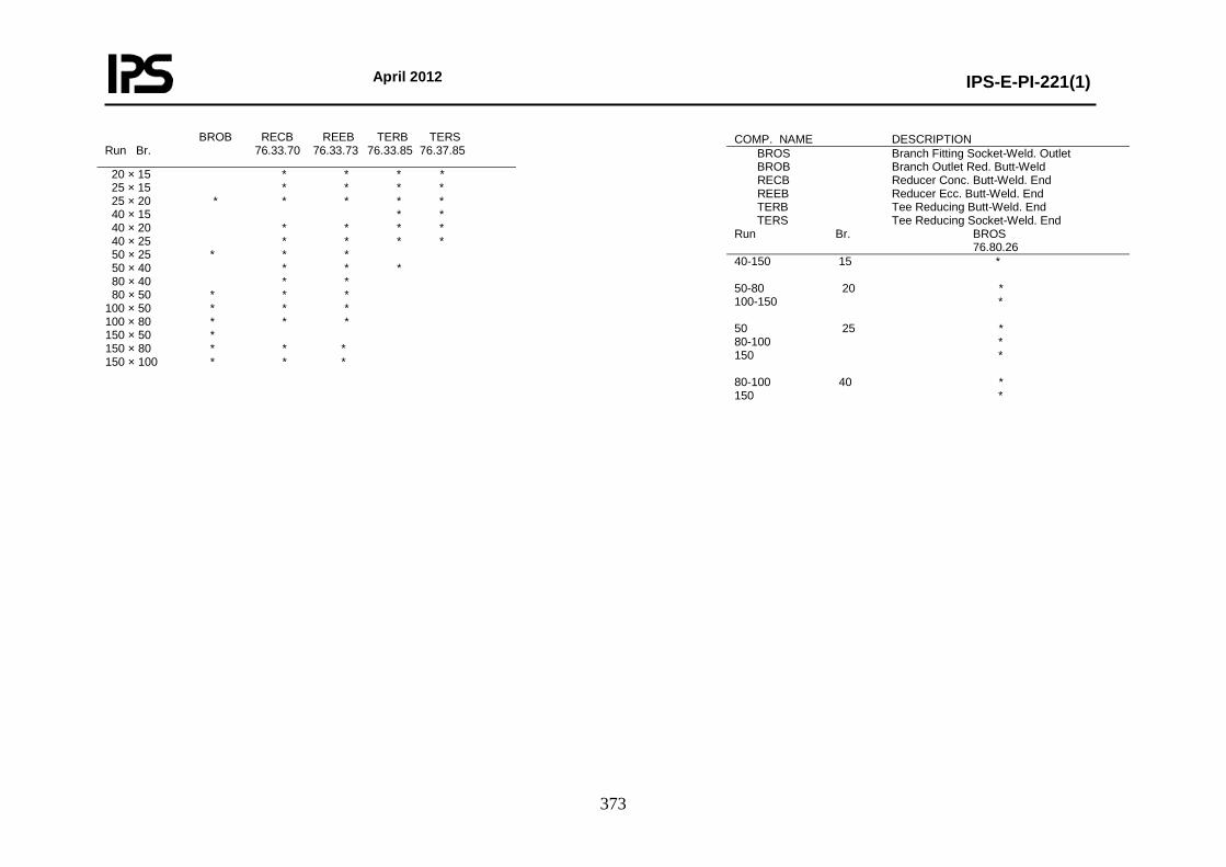
April 2012
IPS-E-PI-221(1)
373
BROB RECB REEB TERB TERS Run Br. 76.33.70 76.33.73 76.33.85 76.37.85
20 × 15 * * * * 25 × 15 * * * * 25 × 20 * * * * * 40 × 15 * * 40 × 20 * * * * 40 × 25 * * * * 50 × 25 * * * 50 × 40 * * * 80 × 40 * * 80 × 50 * * * 100 × 50 * * * 100 × 80 * * * 150 × 50 * 150 × 80 * * * 150 × 100 * * *
COMP. NAME DESCRIPTION BROS Branch Fitting Socket-Weld. Outlet BROB Branch Outlet Red. Butt-Weld RECB Reducer Conc. Butt-Weld. End REEB Reducer Ecc. Butt-Weld. End TERB Tee Reducing Butt-Weld. End TERS Tee Reducing Socket-Weld. End Run Br. BROS 76.80.26 40-150 15 * 50-80 20 * 100-150 * 50 25 * 80-100 * 150 * 80-100 40 * 150 *
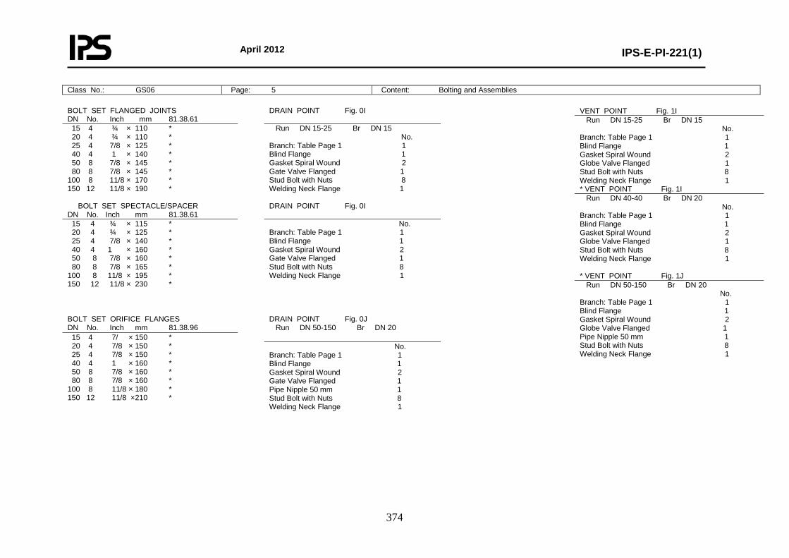
April 2012
IPS-E-PI-221(1)
374
Class No.: GS06 Page: 5 Content: Bolting and Assemblies
BOLT SET FLANGED JOINTS DN No. Inch mm 81.38.61
DRAIN POINT Fig. 0I
15 4 ¾ × 110 * 20 4 ¾ × 110 * 25 4 7/8 × 125 * 40 4 1 × 140 * 50 8 7/8 × 145 * 80 8 7/8 × 145 * 100 8 11/8 × 170 * 150 12 11/8 × 190 *
Run DN 15-25 Br DN 15 No. Branch: Table Page 1 1 Blind Flange 1 Gasket Spiral Wound 2 Gate Valve Flanged 1 Stud Bolt with Nuts 8 Welding Neck Flange 1
BOLT SET SPECTACLE/SPACER DN No. Inch mm 81.38.61
DRAIN POINT Fig. 0I
15 4 ¾ × 115 * 20 4 ¾ × 125 * 25 4 7/8 × 140 * 40 4 1 × 160 * 50 8 7/8 × 160 * 80 8 7/8 × 165 * 100 8 11/8 × 195 * 150 12 11/8 × 230 *
No. Branch: Table Page 1 1 Blind Flange 1 Gasket Spiral Wound 2 Gate Valve Flanged 1 Stud Bolt with Nuts 8 Welding Neck Flange 1
BOLT SET ORIFICE FLANGES DN No. Inch mm 81.38.96
DRAIN POINT Fig. 0J Run DN 50-150 Br DN 20 15 4 7/ × 150 *
20 4 7/8 × 150 * 25 4 7/8 × 150 * 40 4 1 × 160 * 50 8 7/8 × 160 * 80 8 7/8 × 160 * 100 8 11/8 × 180 * 150 12 11/8 × 210 *
No. Branch: Table Page 1 1 Blind Flange 1 Gasket Spiral Wound 2 Gate Valve Flanged 1 Pipe Nipple 50 mm 1 Stud Bolt with Nuts 8 Welding Neck Flange 1
VENT POINT Fig. 1I Run DN 15-25 Br DN 15 No. Branch: Table Page 1 1 Blind Flange 1 Gasket Spiral Wound 2 Globe Valve Flanged 1 Stud Bolt with Nuts 8 Welding Neck Flange 1 * VENT POINT Fig. 1I Run DN 40-40 Br DN 20 No. Branch: Table Page 1 1 Blind Flange 1 Gasket Spiral Wound 2 Globe Valve Flanged 1 Stud Bolt with Nuts 8 Welding Neck Flange 1 * VENT POINT Fig. 1J Run DN 50-150 Br DN 20 No. Branch: Table Page 1 1 Blind Flange 1 Gasket Spiral Wound 2 Globe Valve Flanged 1 Pipe Nipple 50 mm 1 Stud Bolt with Nuts 8 Welding Neck Flange 1
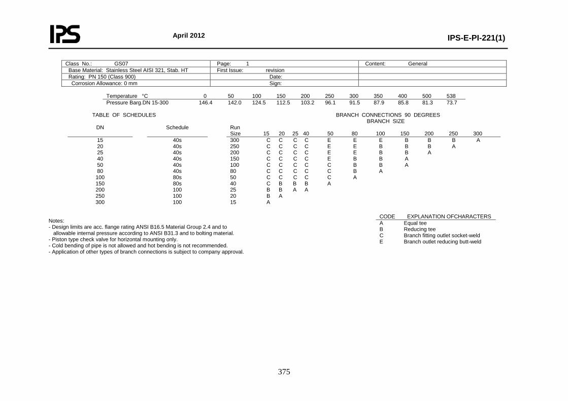
April 2012
IPS-E-PI-221(1)
375
Class No.: GS07 Page: 1 Content: General Base Material: Stainless Steel AISI 321, Stab. HT First Issue: revision Rating: PN 150 (Class 900) Date: Corrosion Allowance: 0 mm Sign:
Temperature °C 0 50 100 150 200 250 300 350 400 500 538 Pressure Barg.DN 15-300 146.4 142.0 124.5 112.5 103.2 96.1 91.5 87.9 85.8 81.3 73.7
TABLE OF SCHEDULES BRANCH CONNECTIONS 90 DEGREES BRANCH SIZE
DN Schedule Run Size 15 20 25 40 50 80 100 150 200 250 300
15 20 25 40 50 80
100 150 200 250 300
40s 40s 40s 40s 40s 40s 80s 80s 100 100 100
300 C C C C E E E B B B A 250 C C C C E E B B B A 200 C C C C E E B B A 150 C C C C E B B A 100 C C C C C B B A 80 C C C C C B A 50 C C C C C A 40 C B B B A 25 B B A A 20 B A 15 A
Notes: - Design limits are acc. flange rating ANSI B16.5 Material Group 2.4 and to allowable internal pressure according to ANSI B31.3 and to bolting material. - Piston type check valve for horizontal mounting only. - Cold bending of pipe is not allowed and hot bending is not recommended. - Application of other types of branch connections is subject to company approval.
CODE EXPLANATION OFCHARACTERS A Equal tee B Reducing tee C Branch fitting outlet socket-weld E Branch outlet reducing butt-weld
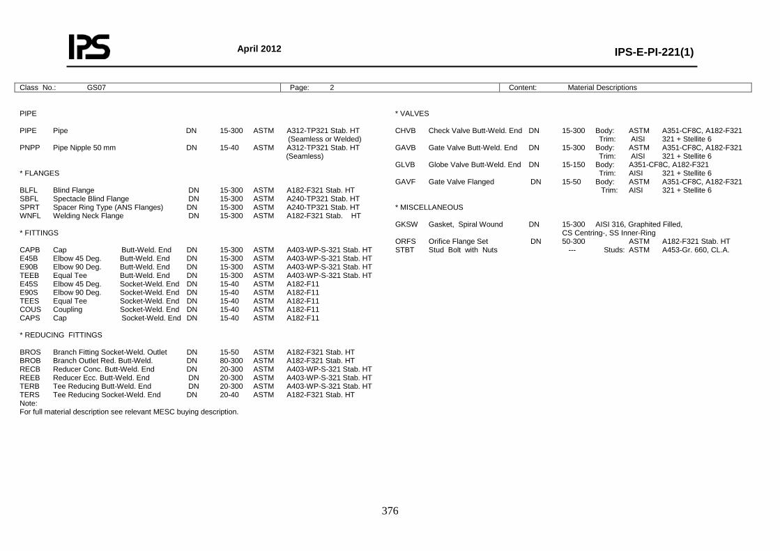
April 2012
IPS-E-PI-221(1)
376
Class No.: GS07 Page: 2 Content: Material Descriptions
PIPE PIPE Pipe DN 15-300 ASTM A312-TP321 Stab. HT (Seamless or Welded) PNPP Pipe Nipple 50 mm DN 15-40 ASTM A312-TP321 Stab. HT (Seamless) * FLANGES BLFL Blind Flange DN 15-300 ASTM A182-F321 Stab. HT SBFL Spectacle Blind Flange DN 15-300 ASTM A240-TP321 Stab. HT SPRT Spacer Ring Type (ANS Flanges) DN 15-300 ASTM A240-TP321 Stab. HT WNFL Welding Neck Flange DN 15-300 ASTM A182-F321 Stab. HT * FITTINGS CAPB Cap Butt-Weld. End DN 15-300 ASTM A403-WP-S-321 Stab. HT E45B Elbow 45 Deg. Butt-Weld. End DN 15-300 ASTM A403-WP-S-321 Stab. HT E90B Elbow 90 Deg. Butt-Weld. End DN 15-300 ASTM A403-WP-S-321 Stab. HT TEEB Equal Tee Butt-Weld. End DN 15-300 ASTM A403-WP-S-321 Stab. HT E45S Elbow 45 Deg. Socket-Weld. End DN 15-40 ASTM A182-F11 E90S Elbow 90 Deg. Socket-Weld. End DN 15-40 ASTM A182-F11 TEES Equal Tee Socket-Weld. End DN 15-40 ASTM A182-F11 COUS Coupling Socket-Weld. End DN 15-40 ASTM A182-F11 CAPS Cap Socket-Weld. End DN 15-40 ASTM A182-F11 * REDUCING FITTINGS BROS Branch Fitting Socket-Weld. Outlet DN 15-50 ASTM A182-F321 Stab. HT BROB Branch Outlet Red. Butt-Weld. DN 80-300 ASTM A182-F321 Stab. HT RECB Reducer Conc. Butt-Weld. End DN 20-300 ASTM A403-WP-S-321 Stab. HT REEB Reducer Ecc. Butt-Weld. End DN 20-300 ASTM A403-WP-S-321 Stab. HT TERB Tee Reducing Butt-Weld. End DN 20-300 ASTM A403-WP-S-321 Stab. HT TERS Tee Reducing Socket-Weld. End DN 20-40 ASTM A182-F321 Stab. HT Note: For full material description see relevant MESC buying description.
* VALVES CHVB Check Valve Butt-Weld. End DN 15-300 Body: ASTM A351-CF8C, A182-F321 Trim: AISI 321 + Stellite 6 GAVB Gate Valve Butt-Weld. End DN 15-300 Body: ASTM A351-CF8C, A182-F321 Trim: AISI 321 + Stellite 6 GLVB Globe Valve Butt-Weld. End DN 15-150 Body: A351-CF8C, A182-F321 Trim: AISI 321 + Stellite 6 GAVF Gate Valve Flanged DN 15-50 Body: ASTM A351-CF8C, A182-F321 Trim: AISI 321 + Stellite 6 * MISCELLANEOUS GKSW Gasket, Spiral Wound DN 15-300 AISI 316, Graphited Filled, CS Centring-, SS Inner-Ring ORFS Orifice Flange Set DN 50-300 ASTM A182-F321 Stab. HT STBT Stud Bolt with Nuts --- Studs: ASTM A453-Gr. 660, CL.A.
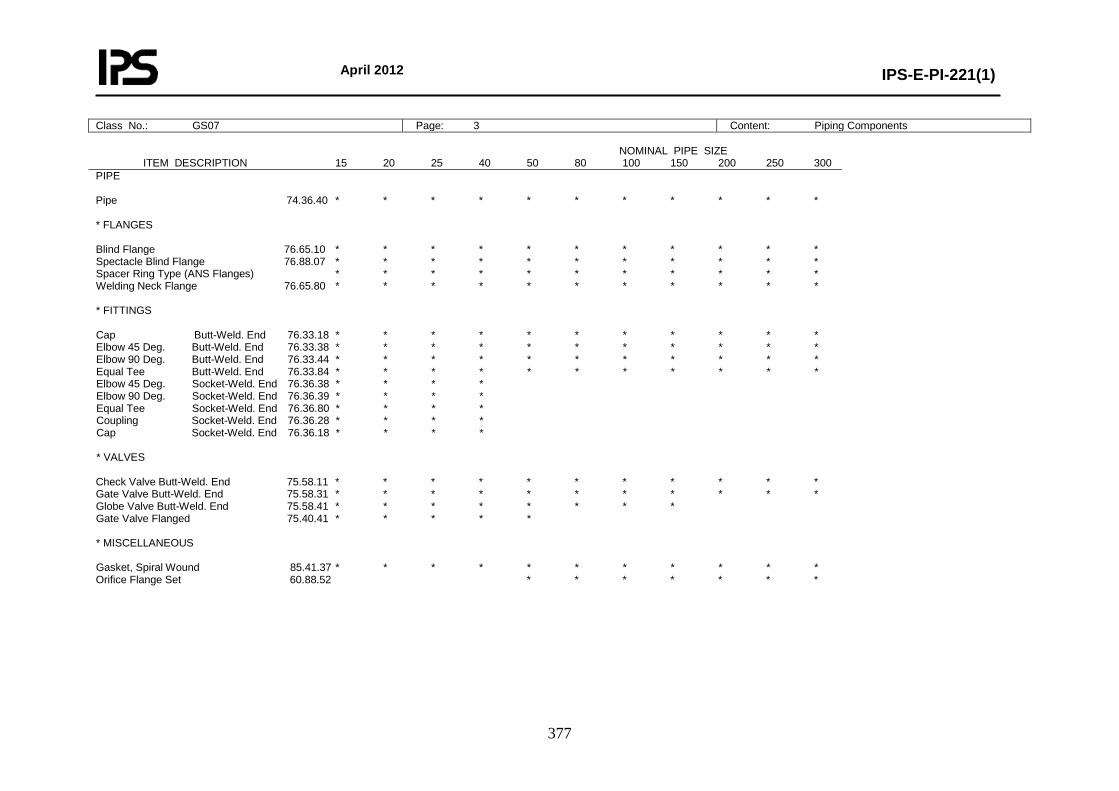
April 2012
IPS-E-PI-221(1)
377
Class No.: GS07 Page: 3 Content: Piping Components NOMINAL PIPE SIZE ITEM DESCRIPTION 15 20 25 40 50 80 100 150 200 250 300 PIPE Pipe 74.36.40 * * * * * * * * * * * * FLANGES Blind Flange 76.65.10 * * * * * * * * * * * Spectacle Blind Flange 76.88.07 * * * * * * * * * * * Spacer Ring Type (ANS Flanges) * * * * * * * * * * * Welding Neck Flange 76.65.80 * * * * * * * * * * * * FITTINGS Cap Butt-Weld. End 76.33.18 * * * * * * * * * * * Elbow 45 Deg. Butt-Weld. End 76.33.38 * * * * * * * * * * * Elbow 90 Deg. Butt-Weld. End 76.33.44 * * * * * * * * * * * Equal Tee Butt-Weld. End 76.33.84 * * * * * * * * * * * Elbow 45 Deg. Socket-Weld. End 76.36.38 * * * * Elbow 90 Deg. Socket-Weld. End 76.36.39 * * * * Equal Tee Socket-Weld. End 76.36.80 * * * * Coupling Socket-Weld. End 76.36.28 * * * * Cap Socket-Weld. End 76.36.18 * * * * * VALVES Check Valve Butt-Weld. End 75.58.11 * * * * * * * * * * * Gate Valve Butt-Weld. End 75.58.31 * * * * * * * * * * * Globe Valve Butt-Weld. End 75.58.41 * * * * * * * * Gate Valve Flanged 75.40.41 * * * * * * MISCELLANEOUS Gasket, Spiral Wound 85.41.37 * * * * * * * * * * * Orifice Flange Set 60.88.52 * * * * * * *
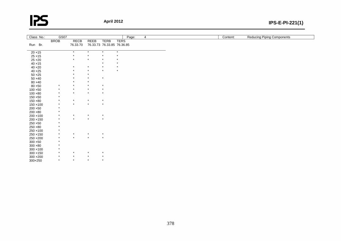
April 2012
IPS-E-PI-221(1)
378
BROB RECB REEB TERB TERS Run Br. 76.33.70 76.33.73 76.33.85 76.36.85 20 ×15 * * * * 25 ×15 * * * * 25 ×20 * * * * 40 ×15 * * 40 ×20 * * * * 40 ×25 * * * * 50 ×25 * * 50 ×40 * * * 80 ×40 * * 80 ×50 * * * * 100 ×50 * * * * 100 ×80 * * * * 150 ×50 * 150 ×80 * * * * 150 ×100 * * * * 200 ×50 * 200 ×80 * 200 ×100 * * * * 200 ×150 * * * * 250 ×50 * 250 ×80 * 250 ×100 * 250 ×150 * * * * 250 ×200 * * * * 300 ×50 * 300 ×80 * 300 ×100 * 300 ×150 * * * * 300 ×200 * * * * 300×250 * * * *
Class No.: GS07 Page: 4 Content: Reducing Piping Components
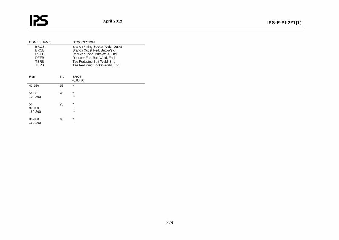
April 2012
IPS-E-PI-221(1)
379
COMP. NAME DESCRIPTION BROS Branch Fitting Socket-Weld. Outlet BROB Branch Outlet Red. Butt-Weld RECB Reducer Conc. Butt-Weld. End REEB Reducer Ecc. Butt-Weld. End TERB Tee Reducing Butt-Weld. End TERS Tee Reducing Socket-Weld. End
Run Br. BROS 76.80.26 40-150 15 * 50-80 20 * 100-300 * 50 25 * 80-100 * 150-300 * 80-100 40 * 150-300 *
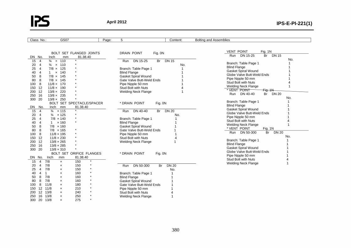
April 2012
IPS-E-PI-221(1)
380
Class No.: GS07 Page: 5 Content: Bolting and Assemblies
BOLT SET FLANGED JOINTS DN No. Inch mm 81.38.40
DRAIN POINT Fig. 0N
15 4 ¾ × 110 * 20 4 ¾ × 110 * 25 4 7/8 × 125 * 40 4 1 × 140 * 50 8 7/8 × 145 * 80 8 7/8 × 145 * 100 8 11/8 × 170 * 150 12 11/8 × 190 * 200 12 13/8 × 220 * 250 16 13/8 × 235 * 300 20 13/8 × 250 *
Run DN 15-25 Br DN 15 No. Branch: Table Page 1 1 Blind Flange 1 Gasket Spiral Wound 1 Gate Valve Butt-Weld Ends 1 Pipe Nipple 50 mm 1 Stud Bolt with Nuts 4 Welding Neck Flange 1
BOLT SET SPECTACLE/SPACER DN No. Inch mm 81.38.40
* DRAIN POINT Fig. 0N
15 4 ¾ × 115 * 20 4 ¾ × 125 * 25 4 7/8 × 140 * 40 4 1 × 160 * 50 8 7/8 × 160 80 8 7/8 × 165 * 100 8 11/8 × 195 * 150 12 11/8 × 230 * 200 12 13/8 × 265 * 250 16 13/8 × 285 * 300 20 13/8 × 310 *
Run DN 40-40 Br DN 20 No. Branch: Table Page 1 1 Blind Flange 1 Gasket Spiral Wound 1 Gate Valve Butt-Weld Ends 1 Pipe Nipple 50 mm 1 Stud Bolt with Nuts 4 Welding Neck Flange 1
BOLT SET ORIFICE FLANGES DN No. Inch mm 81.38.40
* DRAIN POINT Fig. 0N
15 4 7/8 × 150 * 20 4 7/8 × 150 * 25 4 7/8 × 150 * 40 4 1 × 160 * 50 8 7/8 × 160 * 80 8 7/8 × 160 * 100 8 11/8 × 180 * 150 12 11/8 × 210 * 200 12 13/8 × 240 * 250 16 13/8 × 250 * 300 20 13/8 × 275 *
Run DN 50-300 Br DN 20 No. Branch: Table Page 1 1 Blind Flange 1 Gasket Spiral Wound 1 Gate Valve Butt-Weld Ends 1 Pipe Nipple 50 mm 1 Stud Bolt with Nuts 4 Welding Neck Flange 1
VENT POINT Fig. 1N Run DN 15-25 Br DN 15 No. Branch: Table Page 1 1 Blind Flange 1 Gasket Spiral Wound 1 Globe Valve Butt-Weld Ends 1 Pipe Nipple 50 mm 1 Stud Bolt with Nuts 4 Welding Neck Flange 1 * VENT POINT Fig. 1N Run DN 40-40 Br DN 20 No. Branch: Table Page 1 1 Blind Flange 1 Gasket Spiral Wound 1 Globe Valve Butt-Weld Ends 1 Pipe Nipple 50 mm 1 Stud Bolt with Nuts 4 Welding Neck Flange 1 * VENT POINT Fig. 1N Run DN 50-300 Br DN 20 No. Branch: Table Page 1 1 Blind Flange 1 Gasket Spiral Wound 1 Globe Valve Butt-Weld Ends 1 Pipe Nipple 50 mm 1 Stud Bolt with Nuts 4 Welding Neck Flange 1
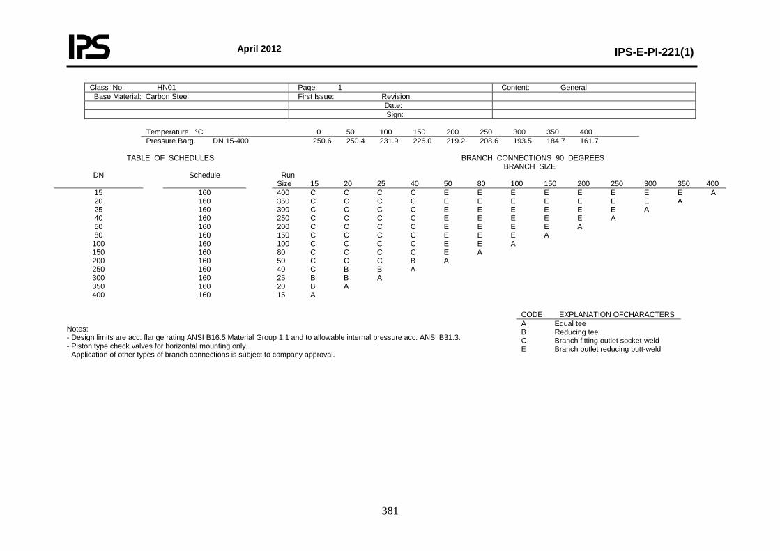
April 2012
IPS-E-PI-221(1)
381
Class No.: HN01 Page: 1 Content: General Base Material: Carbon Steel First Issue: Revision: Date: Sign:
Temperature °C 0 50 100 150 200 250 300 350 400 Pressure Barg. DN 15-400 250.6 250.4 231.9 226.0 219.2 208.6 193.5 184.7 161.7
TABLE OF SCHEDULES BRANCH CONNECTIONS 90 DEGREES BRANCH SIZE
DN Schedule Run Size 15 20 25 40 50 80 100 150 200 250 300 350 400
15 20 25 40 50 80
100 150 200 250 300 350 400
160 160 160 160 160 160 160 160 160 160 160 160 160
400 C C C C E E E E E E E E A 350 C C C C E E E E E E E A 300 C C C C E E E E E E A 250 C C C C E E E E E A 200 C C C C E E E E A 150 C C C C E E E A 100 C C C C E E A 80 C C C C E A 50 C C C B A 40 C B B A 25 B B A 20 B A 15 A
Notes: - Design limits are acc. flange rating ANSI B16.5 Material Group 1.1 and to allowable internal pressure acc. ANSI B31.3. - Piston type check valves for horizontal mounting only. - Application of other types of branch connections is subject to company approval.
CODE EXPLANATION OFCHARACTERS A Equal tee B Reducing tee C Branch fitting outlet socket-weld E Branch outlet reducing butt-weld
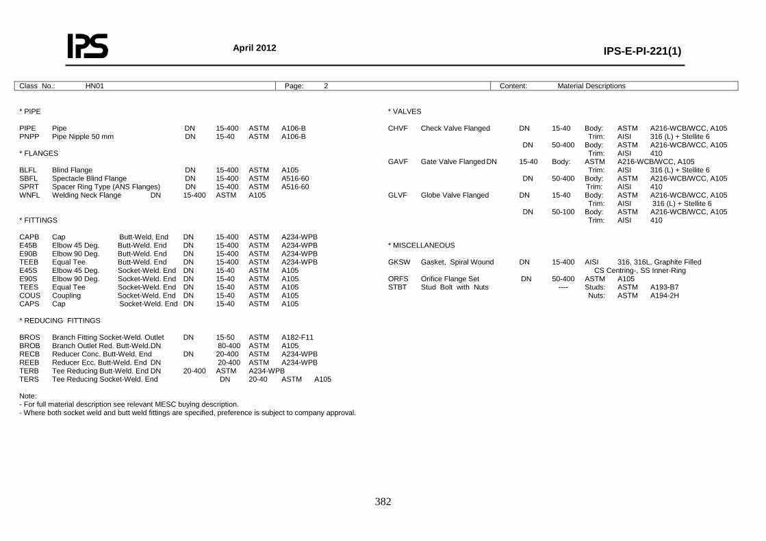
April 2012
IPS-E-PI-221(1)
382
Class No.: HN01 Page: 2 Content: Material Descriptions
* PIPE PIPE Pipe DN 15-400 ASTM A106-B PNPP Pipe Nipple 50 mm DN 15-40 ASTM A106-B * FLANGES BLFL Blind Flange DN 15-400 ASTM A105 SBFL Spectacle Blind Flange DN 15-400 ASTM A516-60 SPRT Spacer Ring Type (ANS Flanges) DN 15-400 ASTM A516-60 WNFL Welding Neck Flange DN 15-400 ASTM A105 * FITTINGS CAPB Cap Butt-Weld. End DN 15-400 ASTM A234-WPB E45B Elbow 45 Deg. Butt-Weld. End DN 15-400 ASTM A234-WPB E90B Elbow 90 Deg. Butt-Weld. End DN 15-400 ASTM A234-WPB TEEB Equal Tee Butt-Weld. End DN 15-400 ASTM A234-WPB E45S Elbow 45 Deg. Socket-Weld. End DN 15-40 ASTM A105 E90S Elbow 90 Deg. Socket-Weld. End DN 15-40 ASTM A105 TEES Equal Tee Socket-Weld. End DN 15-40 ASTM A105 COUS Coupling Socket-Weld. End DN 15-40 ASTM A105 CAPS Cap Socket-Weld. End DN 15-40 ASTM A105 * REDUCING FITTINGS BROS Branch Fitting Socket-Weld. Outlet DN 15-50 ASTM A182-F11 BROB Branch Outlet Red. Butt-Weld. DN 80-400 ASTM A105 RECB Reducer Conc. Butt-Weld. End DN 20-400 ASTM A234-WPB REEB Reducer Ecc. Butt-Weld. End DN 20-400 ASTM A234-WPB TERB Tee Reducing Butt-Weld. End DN 20-400 ASTM A234-WPB TERS Tee Reducing Socket-Weld. End DN 20-40 ASTM A105 Note: - For full material description see relevant MESC buying description. - Where both socket weld and butt weld fittings are specified, preference is subject to company approval.
* VALVES CHVF Check Valve Flanged DN 15-40 Body: ASTM A216-WCB/WCC, A105 Trim: AISI 316 (L) + Stellite 6 DN 50-400 Body: ASTM A216-WCB/WCC, A105 Trim: AISI 410 GAVF Gate Valve Flanged DN 15-40 Body: ASTM A216-WCB/WCC, A105 Trim: AISI 316 (L) + Stellite 6 DN 50-400 Body: ASTM A216-WCB/WCC, A105 Trim: AISI 410 GLVF Globe Valve Flanged DN 15-40 Body: ASTM A216-WCB/WCC, A105 Trim: AISI 316 (L) + Stellite 6 DN 50-100 Body: ASTM A216-WCB/WCC, A105 Trim: AISI 410 * MISCELLANEOUS GKSW Gasket, Spiral Wound DN 15-400 AISI 316, 316L, Graphite Filled CS Centring-, SS Inner-Ring ORFS Orifice Flange Set DN 50-400 ASTM A105 STBT Stud Bolt with Nuts ---- Studs: ASTM A193-B7 Nuts: ASTM A194-2H
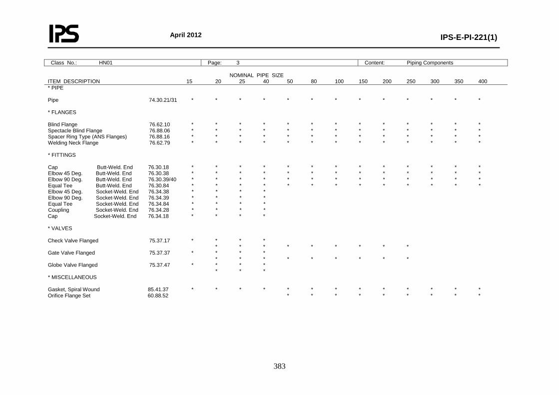
April 2012
IPS-E-PI-221(1)
383
Class No.: HN01 Page: 3 Content: Piping Components NOMINAL PIPE SIZE ITEM DESCRIPTION 15 20 25 40 50 80 100 150 200 250 300 350 400 * PIPE Pipe 74.30.21/31 * * * * * * * * * * * * * * FLANGES Blind Flange 76.62.10 * * * * * * * * * * * * * Spectacle Blind Flange 76.88.06 * * * * * * * * * * * * * Spacer Ring Type (ANS Flanges) 76.88.16 * * * * * * * * * * * * * Welding Neck Flange 76.62.79 * * * * * * * * * * * * * * FITTINGS Cap Butt-Weld. End 76.30.18 * * * * * * * * * * * * * Elbow 45 Deg. Butt-Weld. End 76.30.38 * * * * * * * * * * * * * Elbow 90 Deg. Butt-Weld. End 76.30.39/40 * * * * * * * * * * * * * Equal Tee Butt-Weld. End 76.30.84 * * * * * * * * * * * * * Elbow 45 Deg. Socket-Weld. End 76.34.38 * * * * Elbow 90 Deg. Socket-Weld. End 76.34.39 * * * * Equal Tee Socket-Weld. End 76.34.84 * * * * Coupling Socket-Weld. End 76.34.28 * * * * Cap Socket-Weld. End 76.34.18 * * * * * VALVES Check Valve Flanged 75.37.17 * * * * * * * * * * * * * Gate Valve Flanged 75.37.37 * * * * * * * * * * * * * Globe Valve Flanged 75.37.47 * * * * * * * * MISCELLANEOUS Gasket, Spiral Wound 85.41.37 * * * * * * * * * * * * * Orifice Flange Set 60.88.52 * * * * * * * * *
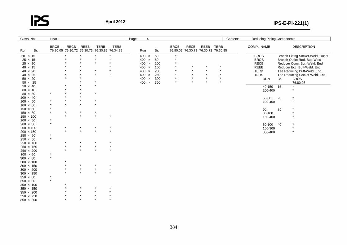
April 2012
IPS-E-PI-221(1)
384
Class No.: HN01 Page: 4 Content: Reducing Piping Components
BROB RECB REEB TERB TERS Run Br. 76.80.05 76.30.72 76.30.73 76.30.85 76.34.85
BROB RECB REEB TERB Run Br. 76.80.05 76.30.72 76.30.73 76.30.85
COMP. NAME DESCRIPTION
20 × 15 * * * * 25 × 15 * * * * 25 × 20 * * * * 40 × 15 * * * 40 × 20 * * * * 40 × 25 * * * * 50 × 20 * * 50 × 25 * * 50 × 40 * * * 80 × 40 * * 80 × 50 * * * * 100 × 40 * * 100 × 50 * * * * 100 × 80 * * * * 150 × 50 * 150 × 80 * * * * 150 × 100 * * * * 200 × 50 * 200 × 80 * 200 × 100 * * * * 200 × 150 * * * * 250 × 50 * 250 × 80 * 250 × 100 * * * * 250 × 150 * * * * 250 × 200 * * * * 300 × 50 * 300 × 80 * 300 × 100 * 300 × 150 * * * * 300 × 200 * * * * 300 × 250 * * * * 350 × 50 * 350 × 80 * 350 × 100 * 350 × 150 * * * * 350 × 200 * * * * 350 × 250 * * * * 350 × 300 * * * *
400 × 50 * 400 × 80 * 400 × 100 * 400 × 150 * * * * 400 × 200 * * * * 400 × 250 * * * * 400 × 300 * * * * 400 × 350 * * * *
BROS Branch Fitting Socket-Weld. Outlet BROB Branch Outlet Red. Butt-Weld RECB Reducer Conc. Butt-Weld. End REEB Reducer Ecc. Butt-Weld. End TERB Tee Reducing Butt-Weld. End TERS Tee Reducing Socket-Weld. End
RUN Br. BROS 76.80.26
40-150 15 * 200-400 * 50-80 20 * 100-400 * 50 25 * 80-100 * 150-400 * 80-100 40 * 150-300 * 350-400 *
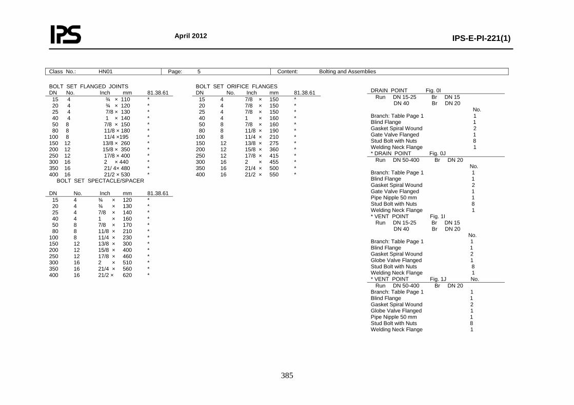
April 2012
IPS-E-PI-221(1)
385
Class No.: HN01 Page: 5 Content: Bolting and Assemblies
BOLT SET FLANGED JOINTS DN No. Inch mm 81.38.61
BOLT SET ORIFICE FLANGES DN No. Inch mm 81.38.61
15 4 ¾ × 110 * 20 4 ¾ × 120 * 25 4 7/8 × 130 * 40 4 1 × 140 * 50 8 7/8 × 150 * 80 8 11/8 × 180 * 100 8 11/4 ×195 * 150 12 13/8 × 260 * 200 12 15/8 × 350 * 250 12 17/8 × 400 * 300 16 2 × 440 * 350 16 21/ 4× 480 * 400 16 21/2 × 530 *
15 4 7/8 × 150 * 20 4 7/8 × 150 * 25 4 7/8 × 150 * 40 4 1 × 160 * 50 8 7/8 × 160 * 80 8 11/8 × 190 * 100 8 11/4 × 210 * 150 12 13/8 × 275 * 200 12 15/8 × 360 * 250 12 17/8 × 415 * 300 16 2 × 455 * 350 16 21/4 × 500 * 400 16 21/2 × 550 *
BOLT SET SPECTACLE/SPACER DN No. Inch mm 81.38.61
15 4 ¾ × 120 * 20 4 ¾ × 130 * 25 4 7/8 × 140 * 40 4 1 × 160 * 50 8 7/8 × 170 * 80 8 11/8 × 210 * 100 8 11/4 × 230 * 150 12 13/8 × 300 * 200 12 15/8 × 400 * 250 12 17/8 × 460 * 300 16 2 × 510 * 350 16 21/4 × 560 * 400 16 21/2 × 620 *
DRAIN POINT Fig. 0I Run DN 15-25 Br DN 15 DN 40 Br DN 20 No. Branch: Table Page 1 1 Blind Flange 1 Gasket Spiral Wound 2 Gate Valve Flanged 1 Stud Bolt with Nuts 8 Welding Neck Flange 1 * DRAIN POINT Fig. 0J Run DN 50-400 Br DN 20 No. Branch: Table Page 1 1 Blind Flange 1 Gasket Spiral Wound 2 Gate Valve Flanged 1 Pipe Nipple 50 mm 1 Stud Bolt with Nuts 8 Welding Neck Flange 1 * VENT POINT Fig. 1I Run DN 15-25 Br DN 15 DN 40 Br DN 20 No. Branch: Table Page 1 1 Blind Flange 1 Gasket Spiral Wound 2 Globe Valve Flanged 1 Stud Bolt with Nuts 8 Welding Neck Flange 1 * VENT POINT Fig. 1J No. Run DN 50-400 Br DN 20 Branch: Table Page 1 1 Blind Flange 1 Gasket Spiral Wound 2 Globe Valve Flanged 1 Pipe Nipple 50 mm 1 Stud Bolt with Nuts 8 Welding Neck Flange 1
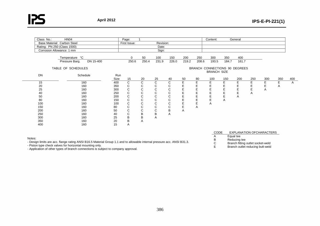
April 2012
IPS-E-PI-221(1)
386
Class No.: HN04 Page: 1 Content: General Base Material: Carbon Steel First Issue: Revision: Rating: PN 250 (Class 1500) Date: Corrosion Allowance: 1 mm Sign:
Temperature °C 0 50 100 150 200 250 300 350 400 Pressure Barg. DN 15-400 250.6 250.4 231.9 226.0 219.2 208.6 193.5 184.7 161.7
TABLE OF SCHEDULES BRANCH CONNECTIONS 90 DEGREES BRANCH SIZE
DN Schedule Run Size 15 20 25 40 50 80 100 150 200 250 300 350 400
15 20 25 40 50 80
100 150 200 250 300 350 400
160 160 160 160 160 160 160 160 160 160 160 160 160
400 C C C C E E E E E E E E A 350 C C C C E E E E E E E A 300 C C C C E E E E E E A 250 C C C C E E E E E A 200 C C C C E E E E A 150 C C C C E E E A 100 C C C C E E A 80 C C C C E A 50 C C C B A 40 C B B A 25 B B A 20 B A 15 A
Notes: - Design limits are acc. flange rating ANSI B16.5 Material Group 1.1 and to allowable internal pressure acc. ANSI B31.3. - Piston type check valves for horizontal mounting only. - Application of other types of branch connections is subject to company approval.
CODE EXPLANATION OFCHARACTERS A Equal tee B Reducing tee C Branch fitting outlet socket-weld E Branch outlet reducing butt-weld
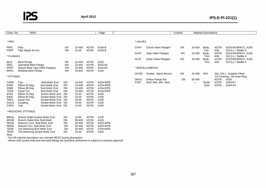
April 2012
IPS-E-PI-221(1)
387
Class No.: HN04 Page: 2 Content: Material Descriptions
* PIPE PIPE Pipe DN 15-400 ASTM A106-B PNPP Pipe Nipple 50 mm DN 15-40 ASTM A106-B * FLANGES BLFL Blind Flange DN 15-400 ASTM A105 SBFL Spectacle Blind Flange DN 15-400 ASTM A516-60 SPRT Spacer Ring Type (ANS Flanges) DN 15-400 ASTM A516-60 WNFL Welding Neck Flange DN 15-400 ASTM A105 * FITTINGS CAPB Cap Butt-Weld. End DN 15-400 ASTM A234-WPB E45B Elbow 45 Deg. Butt-Weld. End DN 15-400 ASTM A234-WPB E90B Elbow 90 Deg. Butt-Weld. End DN 15-400 ASTM A234-WPB TEEB Equal Tee Butt-Weld. End DN 15-400 ASTM A234-WPB E45S Elbow 45 Deg. Socket-Weld. End DN 15-40 ASTM A105 E90S Elbow 90 Deg. Socket-Weld. End DN 15-40 ASTM A105 TEES Equal Tee Socket-Weld. End DN 15-40 ASTM A105 COUS Coupling Socket-Weld. End DN 15-40 ASTM A105 CAPS Cap Socket-Weld. End DN 15-40 ASTM A105 * REDUCING FITTINGS BROS Branch Outlet Socket-Weld. End DN 15-50 ASTM A105 BROB Branch Outlet Red. Butt-Weld. DN 80-400 ASTM A105 RECB Reducer Conc. Butt-Weld. End DN 20-400 ASTM A234-WPB REEB Reducer Ecc. Butt-Weld. End DN 20-400 ASTM A234-WPB TERB Tee Reducing Butt-Weld. End DN 20-400 ASTM A234-WPB TERS Tee Reducing Socket-Weld. End DN 20-40 ASTM A105 Note: - For full material description see relevant MESC buying description. - Where both socket weld and butt weld fittings are specified, preference is subject to company approval.
* VALVES CHVF Check Valve Flanged DN 15-400 Body: ASTM A216-WCB/WCC, A105 Trim: AISI 316 (L) + Stellite 6 GAVF Gate Valve Flanged DN 15-400 Body: ASTM A216-WCB/WCC, A105 Trim: AISI 316 (L) + Stellite 6 GLVF Globe Valve Flanged DN 15-100 Body: ASTM A216-WCB/WCC, A105 Trim: AISI 316 (L) + Stellite 6 * MISCELLANEOUS GKSW Gasket, Spiral Wound DN 15-400 AISI 316, 316 L, Graphite Filled CS Centring-, SS Inner-Ring ORFS Orifice Flange Set DN 50-400 ASTM A105 STBT Stud Bolt with Nuts --- Studs: ASTM A193-B7 Nuts: ASTM A194-2H
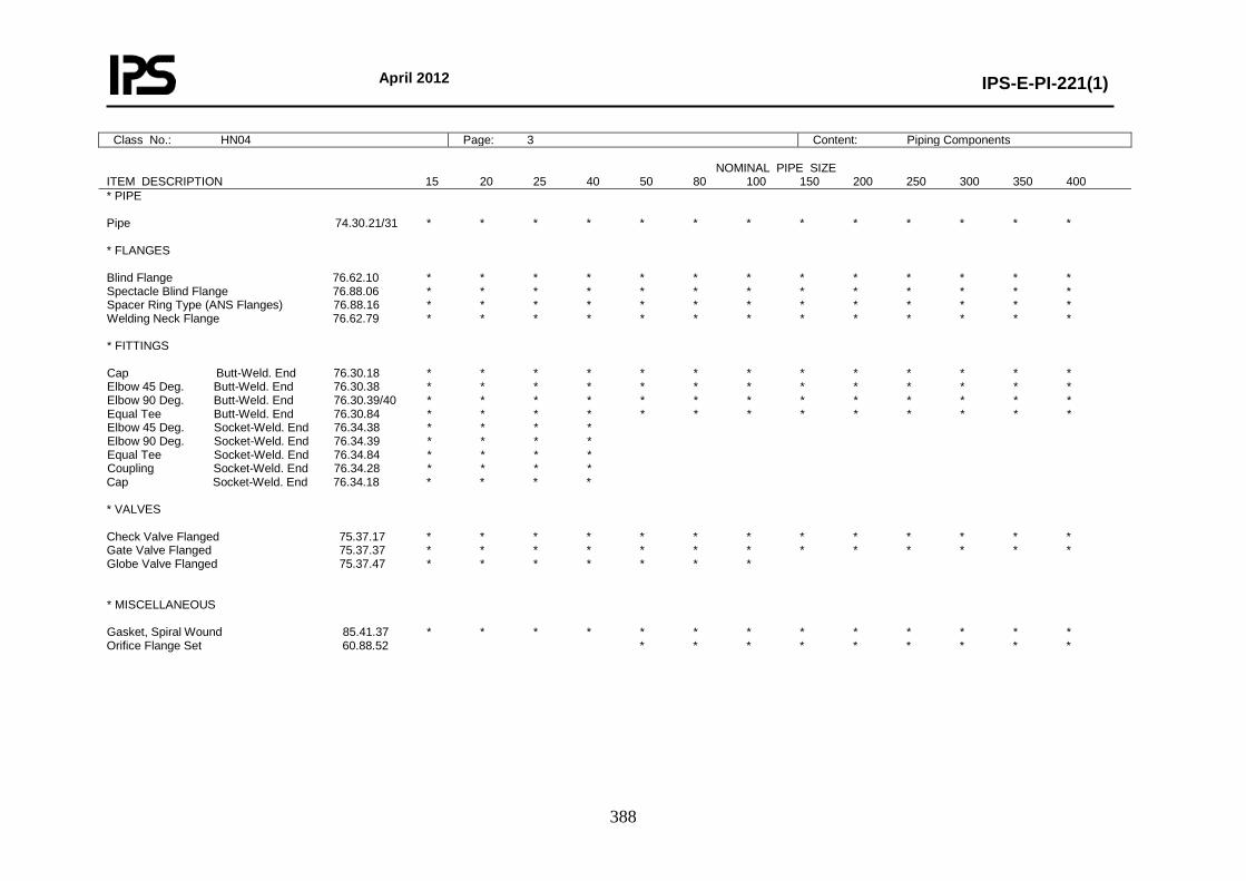
April 2012
IPS-E-PI-221(1)
388
Class No.: HN04 Page: 3 Content: Piping Components NOMINAL PIPE SIZE ITEM DESCRIPTION 15 20 25 40 50 80 100 150 200 250 300 350 400 * PIPE Pipe 74.30.21/31 * * * * * * * * * * * * * * FLANGES Blind Flange 76.62.10 * * * * * * * * * * * * * Spectacle Blind Flange 76.88.06 * * * * * * * * * * * * * Spacer Ring Type (ANS Flanges) 76.88.16 * * * * * * * * * * * * * Welding Neck Flange 76.62.79 * * * * * * * * * * * * * * FITTINGS Cap Butt-Weld. End 76.30.18 * * * * * * * * * * * * * Elbow 45 Deg. Butt-Weld. End 76.30.38 * * * * * * * * * * * * * Elbow 90 Deg. Butt-Weld. End 76.30.39/40 * * * * * * * * * * * * * Equal Tee Butt-Weld. End 76.30.84 * * * * * * * * * * * * * Elbow 45 Deg. Socket-Weld. End 76.34.38 * * * * Elbow 90 Deg. Socket-Weld. End 76.34.39 * * * * Equal Tee Socket-Weld. End 76.34.84 * * * * Coupling Socket-Weld. End 76.34.28 * * * * Cap Socket-Weld. End 76.34.18 * * * * * VALVES Check Valve Flanged 75.37.17 * * * * * * * * * * * * * Gate Valve Flanged 75.37.37 * * * * * * * * * * * * * Globe Valve Flanged 75.37.47 * * * * * * * * MISCELLANEOUS Gasket, Spiral Wound 85.41.37 * * * * * * * * * * * * * Orifice Flange Set 60.88.52 * * * * * * * * *
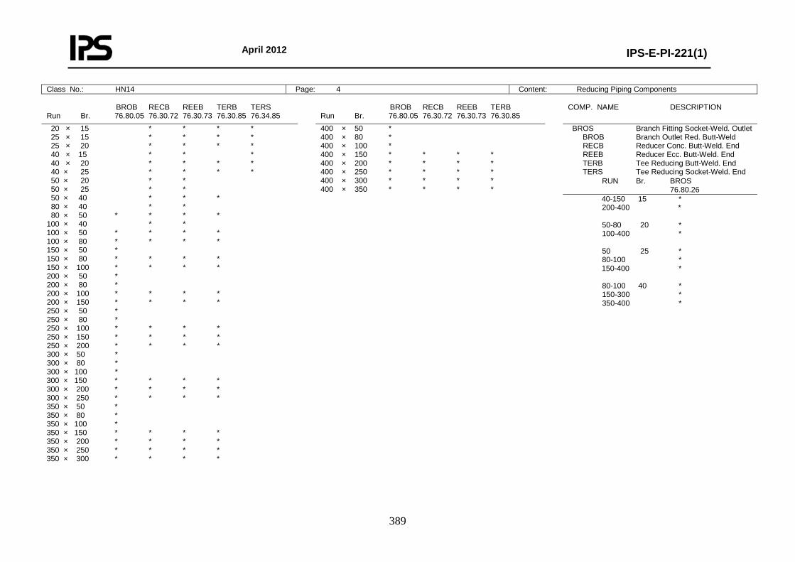
April 2012
IPS-E-PI-221(1)
389
Class No.: HN14 Page: 4 Content: Reducing Piping Components
BROB RECB REEB TERB TERS Run Br. 76.80.05 76.30.72 76.30.73 76.30.85 76.34.85
BROB RECB REEB TERB Run Br. 76.80.05 76.30.72 76.30.73 76.30.85
COMP. NAME DESCRIPTION
20 × 15 * * * * 25 × 15 * * * * 25 × 20 * * * * 40 × 15 * * * 40 × 20 * * * * 40 × 25 * * * * 50 × 20 * * 50 × 25 * * 50 × 40 * * * 80 × 40 * * 80 × 50 * * * * 100 × 40 * * 100 × 50 * * * * 100 × 80 * * * * 150 × 50 * 150 × 80 * * * * 150 × 100 * * * * 200 × 50 * 200 × 80 * 200 × 100 * * * * 200 × 150 * * * * 250 × 50 * 250 × 80 * 250 × 100 * * * * 250 × 150 * * * * 250 × 200 * * * * 300 × 50 * 300 × 80 * 300 × 100 * 300 × 150 * * * * 300 × 200 * * * * 300 × 250 * * * * 350 × 50 * 350 × 80 * 350 × 100 * 350 × 150 * * * * 350 × 200 * * * * 350 × 250 * * * * 350 × 300 * * * *
400 × 50 * 400 × 80 * 400 × 100 * 400 × 150 * * * * 400 × 200 * * * * 400 × 250 * * * * 400 × 300 * * * * 400 × 350 * * * *
BROS Branch Fitting Socket-Weld. Outlet BROB Branch Outlet Red. Butt-Weld RECB Reducer Conc. Butt-Weld. End REEB Reducer Ecc. Butt-Weld. End TERB Tee Reducing Butt-Weld. End TERS Tee Reducing Socket-Weld. End
RUN Br. BROS 76.80.26
40-150 15 * 200-400 * 50-80 20 * 100-400 * 50 25 * 80-100 * 150-400 * 80-100 40 * 150-300 * 350-400 *
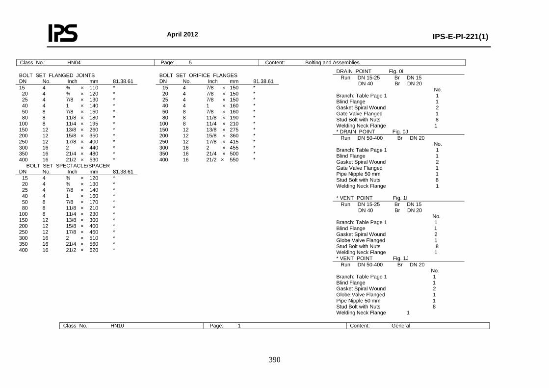
April 2012
IPS-E-PI-221(1)
390
Class No.: HN10 Page: 1 Content: General
Class No.: HN04 Page: 5 Content: Bolting and Assemblies
BOLT SET FLANGED JOINTS DN No. Inch mm 81.38.61
BOLT SET ORIFICE FLANGES DN No. Inch mm 81.38.61
15 4 ¾ × 110 * 20 4 ¾ × 120 * 25 4 7/8 × 130 * 40 4 1 × 140 * 50 8 7/8 × 150 * 80 8 11/8 × 180 * 100 8 11/4 × 195 * 150 12 13/8 × 260 * 200 12 15/8 × 350 * 250 12 17/8 × 400 * 300 16 2 × 440 * 350 16 21/4 × 480 * 400 16 21/2 × 530 *
15 4 7/8 × 150 * 20 4 7/8 × 150 * 25 4 7/8 × 150 * 40 4 1 × 160 * 50 8 7/8 × 160 * 80 8 11/8 × 190 * 100 8 11/4 × 210 * 150 12 13/8 × 275 * 200 12 15/8 × 360 * 250 12 17/8 × 415 * 300 16 2 × 455 * 350 16 21/4 × 500 * 400 16 21/2 × 550 *
BOLT SET SPECTACLE/SPACER DN No. Inch mm 81.38.61
15 4 ¾ × 120 * 20 4 ¾ × 130 * 25 4 7/8 × 140 * 40 4 1 × 160 * 50 8 7/8 × 170 * 80 8 11/8 × 210 * 100 8 11/4 × 230 * 150 12 13/8 × 300 * 200 12 15/8 × 400 * 250 12 17/8 × 460 * 300 16 2 × 510 * 350 16 21/4 × 560 * 400 16 21/2 × 620 *
DRAIN POINT Fig. 0I Run DN 15-25 Br DN 15 DN 40 Br DN 20 No. Branch: Table Page 1 1 Blind Flange 1 Gasket Spiral Wound 2 Gate Valve Flanged 1 Stud Bolt with Nuts 8 Welding Neck Flange 1 * DRAIN POINT Fig. 0J Run DN 50-400 Br DN 20 No. Branch: Table Page 1 1 Blind Flange 1 Gasket Spiral Wound 2 Gate Valve Flanged 1 Pipe Nipple 50 mm 1 Stud Bolt with Nuts 8 Welding Neck Flange 1 * VENT POINT Fig. 1I Run DN 15-25 Br DN 15 DN 40 Br DN 20 No. Branch: Table Page 1 1 Blind Flange 1 Gasket Spiral Wound 2 Globe Valve Flanged 1 Stud Bolt with Nuts 8 Welding Neck Flange 1 * VENT POINT Fig. 1J Run DN 50-400 Br DN 20 No. Branch: Table Page 1 1 Blind Flange 1 Gasket Spiral Wound 2 Globe Valve Flanged 1 Pipe Nipple 50 mm 1 Stud Bolt with Nuts 8 Welding Neck Flange 1
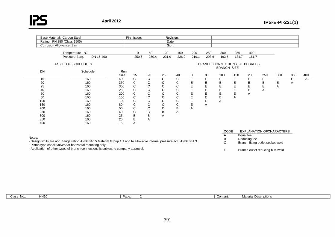
April 2012
IPS-E-PI-221(1)
391
Base Material: Carbon Steel First Issue: Revision: Rating: PN 250 (Class 1500) Date: Corrosion Allowance: 1 mm Sign:
Temperature °C 0 50 100 150 200 250 300 350 400 Pressure Barg. DN 15-400 250.6 250.4 231.9 226.0 219.1 208.6 193.5 184.7 161.7
TABLE OF SCHEDULES BRANCH CONNECTIONS 90 DEGREES BRANCH SIZE
DN Schedule Run Size 15 20 25 40 50 80 100 150 200 250 300 350 400
15 20 25 40 50 80
100 150 200 250 300 350 400
160 160 160 160 160 160 160 160 160 160 160 160 160
400 C C C C E E E E E E E E A 350 C C C C E E E E E E E A 300 C C C C E E E E E E A 250 C C C C E E E E E A 200 C C C C E E E E A 150 C C C C E E E A 100 C C C C E E A 80 C C C C E A 50 C C C B A 40 C B B A 25 B B A 20 B A 15 A
Notes: - Design limits are acc. flange rating ANSI B16.5 Material Group 1.1 and to allowable internal pressure acc. ANSI B31.3. - Piston type check valves for horizontal mounting only. - Application of other types of branch connections is subject to company approval.
Class No.: HN10 Page: 2 Content: Material Descriptions
CODE EXPLANATION OFCHARACTERS A Equal tee B Reducing tee C Branch fitting outlet socket-weld E Branch outlet reducing butt-weld
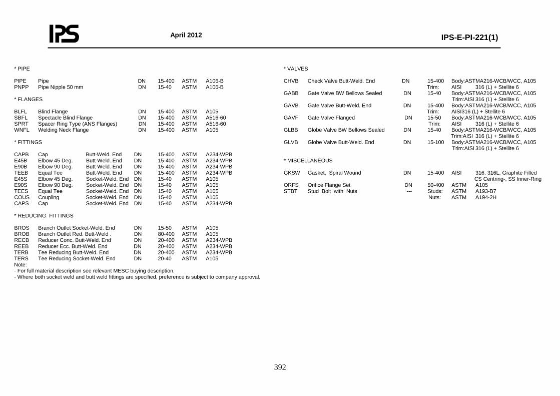
April 2012
IPS-E-PI-221(1)
392
* PIPE PIPE Pipe DN 15-400 ASTM A106-B PNPP Pipe Nipple 50 mm DN 15-40 ASTM A106-B * FLANGES BLFL Blind Flange DN 15-400 ASTM A105 SBFL Spectacle Blind Flange DN 15-400 ASTM A516-60 SPRT Spacer Ring Type (ANS Flanges) DN 15-400 ASTM A516-60 WNFL Welding Neck Flange DN 15-400 ASTM A105 * FITTINGS CAPB Cap Butt-Weld. End DN 15-400 ASTM A234-WPB E45B Elbow 45 Deg. Butt-Weld. End DN 15-400 ASTM A234-WPB E90B Elbow 90 Deg. Butt-Weld. End DN 15-400 ASTM A234-WPB TEEB Equal Tee Butt-Weld. End DN 15-400 ASTM A234-WPB E45S Elbow 45 Deg. Socket-Weld. End DN 15-40 ASTM A105 E90S Elbow 90 Deg. Socket-Weld. End DN 15-40 ASTM A105 TEES Equal Tee Socket-Weld. End DN 15-40 ASTM A105 COUS Coupling Socket-Weld. End DN 15-40 ASTM A105 CAPS Cap Socket-Weld. End DN 15-40 ASTM A234-WPB * REDUCING FITTINGS BROS Branch Outlet Socket-Weld. End DN 15-50 ASTM A105 BROB Branch Outlet Red. Butt-Weld . DN 80-400 ASTM A105 RECB Reducer Conc. Butt-Weld. End DN 20-400 ASTM A234-WPB REEB Reducer Ecc. Butt-Weld. End DN 20-400 ASTM A234-WPB TERB Tee Reducing Butt-Weld. End DN 20-400 ASTM A234-WPB TERS Tee Reducing Socket-Weld. End DN 20-40 ASTM A105 Note: - For full material description see relevant MESC buying description. - Where both socket weld and butt weld fittings are specified, preference is subject to company approval.
* VALVES CHVB Check Valve Butt-Weld. End DN 15-400 Body:ASTMA216-WCB/WCC, A105 Trim: AISI 316 (L) + Stellite 6 GABB Gate Valve BW Bellows Sealed DN 15-40 Body:ASTMA216-WCB/WCC, A105 Trim:AISI 316 (L) + Stellite 6 GAVB Gate Valve Butt-Weld. End DN 15-400 Body:ASTMA216-WCB/WCC, A105 Trim: AISI316 (L) + Stellite 6 GAVF Gate Valve Flanged DN 15-50 Body:ASTMA216-WCB/WCC, A105 Trim: AISI 316 (L) + Stellite 6 GLBB Globe Valve BW Bellows Sealed DN 15-40 Body:ASTMA216-WCB/WCC, A105 Trim:AISI 316 (L) + Stellite 6 GLVB Globe Valve Butt-Weld. End DN 15-100 Body:ASTMA216-WCB/WCC, A105 Trim:AISI 316 (L) + Stellite 6 * MISCELLANEOUS GKSW Gasket, Spiral Wound DN 15-400 AISI 316, 316L, Graphite Filled CS Centring-, SS Inner-Ring ORFS Orifice Flange Set DN 50-400 ASTM A105 STBT Stud Bolt with Nuts --- Studs: ASTM A193-B7 Nuts: ASTM A194-2H
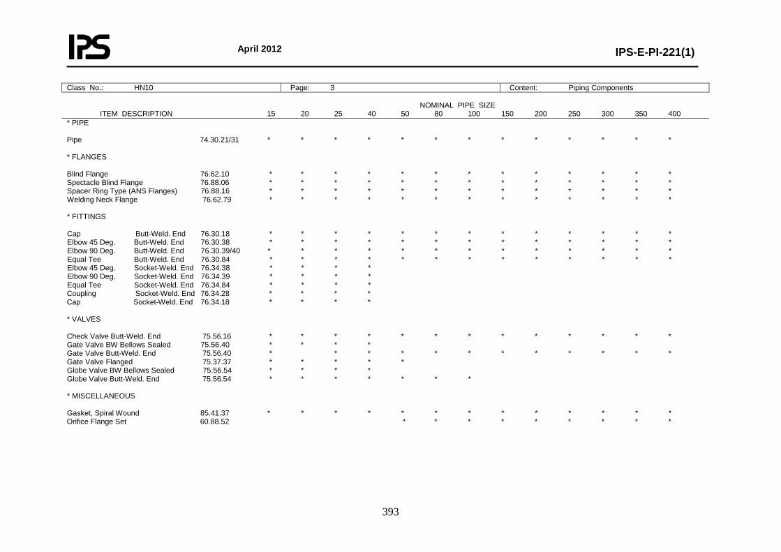
April 2012
IPS-E-PI-221(1)
393
Class No.: HN10 Page: 3 Content: Piping Components NOMINAL PIPE SIZE ITEM DESCRIPTION 15 20 25 40 50 80 100 150 200 250 300 350 400 * PIPE Pipe 74.30.21/31 * * * * * * * * * * * * * * FLANGES Blind Flange 76.62.10 * * * * * * * * * * * * * Spectacle Blind Flange 76.88.06 * * * * * * * * * * * * * Spacer Ring Type (ANS Flanges) 76.88.16 * * * * * * * * * * * * * Welding Neck Flange 76.62.79 * * * * * * * * * * * * * * FITTINGS Cap Butt-Weld. End 76.30.18 * * * * * * * * * * * * * Elbow 45 Deg. Butt-Weld. End 76.30.38 * * * * * * * * * * * * * Elbow 90 Deg. Butt-Weld. End 76.30.39/40 * * * * * * * * * * * * * Equal Tee Butt-Weld. End 76.30.84 * * * * * * * * * * * * * Elbow 45 Deg. Socket-Weld. End 76.34.38 * * * * Elbow 90 Deg. Socket-Weld. End 76.34.39 * * * * Equal Tee Socket-Weld. End 76.34.84 * * * * Coupling Socket-Weld. End 76.34.28 * * * * Cap Socket-Weld. End 76.34.18 * * * * * VALVES Check Valve Butt-Weld. End 75.56.16 * * * * * * * * * * * * * Gate Valve BW Bellows Sealed 75.56.40 * * * * Gate Valve Butt-Weld. End 75.56.40 * * * * * * * * * * * * Gate Valve Flanged 75.37.37 * * * * * Globe Valve BW Bellows Sealed 75.56.54 * * * * Globe Valve Butt-Weld. End 75.56.54 * * * * * * * * MISCELLANEOUS Gasket, Spiral Wound 85.41.37 * * * * * * * * * * * * * Orifice Flange Set 60.88.52 * * * * * * * * *
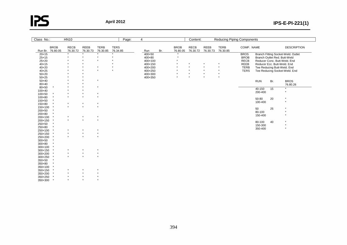
April 2012
IPS-E-PI-221(1)
394
Class No.: HN10 Page: 4 Content: Reducing Piping Components
BROB RECB REEB TERB TERS Run Br. 76.80.05 76.30.72 76.30.73 76.30.85 76.34.85
BROB RECB REEB TERB Run Br. 76.80.05 76.30.72 76.30.73 76.30.85
COMP. NAME DESCRIPTION
20×15 * * * * 25×15 * * * * 25×20 * * * * 40×15 * * * 40×20 * * * * 40×25 * * * * 50×20 * * 50×25 * * 50×40 * * * 80×40 * * 80×50 * * * * 100×40 * * 100×50 * * * * 100×80 * * * * 150×50 * 150×80 * * * * 150×100 * * * * 200×50 * 200×80 * 200×100 * * * * 200×150 * * * * 250×50 * 250×80 * 250×100 * * * * 250×150 * * * * 250×200 * * * * 300×50 * 300×80 * 300×100 * 300×150 * * * * 300×200 * * * * 300×250 * * * * 350×50 * 350×80 * 350×100 * 350×150 * * * * 350×200 * * * * 350×250 * * * * 350×300 * * * *
400×50 * 400×80 * 400×100 * 400×150 * * * * 400×200 * * * * 400×250 * * * * 400×300 * * * * 400×350 * * * *
BROS Branch Fitting Socket-Weld. Outlet BROB Branch Outlet Red. Butt-Weld RECB Reducer Conc. Butt-Weld. End REEB Reducer Ecc. Butt-Weld. End TERB Tee Reducing Butt-Weld. End TERS Tee Reducing Socket-Weld. End
RUN Br. BROS 76.80.26 40-150 15 * 200-400 * 50-80 20 * 100-400 * 50 25 * 80-100 * 150-400 * 80-100 40 * 150-300 * 350-400 *

April 2012
IPS-E-PI-221(1)
395
Class No.: HN14 Page: 1 Content: General
Class No.: HN10 Page: 4 Content: Reducing Piping Components
BOLT SET FLANGED JOINTS DN No. Inch mm 81.38.61
BOLT SET ORIFICE FLANGES DN No. Inch mm 81.38.61
15 4 ¾ × 110 * 20 4 ¾ × 120 * 25 4 7/8 × 130 * 40 4 1 × 140 * 50 8 7/8 × 150 * 80 8 11/8 × 180 * 100 8 11/4 × 195 * 150 12 13/8 × 260 * 200 12 15/8 × 350 * 250 12 17/8 × 400 * 300 16 2 × 440 * 350 16 21/4 × 480 * 400 16 21/2 × 530 *
15 4 7/8 × 150 * 20 4 7/8 × 150 * 25 4 7/8 × 150 * 40 4 1 × 160 * 50 8 7/8 × 160 * 80 8 11/8 × 190 * 100 8 11/4 × 210 * 150 12 13/8 × 275 * 200 12 15/8 × 360 * 250 12 17/8 × 415 * 300 16 2 × 455 * 350 16 21/4 × 500 * 400 16 21/2 × 550 *
BOLT SET SPECTACLE/SPACER DN No. Inch mm 81.38.61
* DRAIN POINT Fig. 0N
15 4 ¾× 120 * 20 4 3/4× 130 * 25 4 7/8× 140 * 40 4 1× 160 * 50 8 7/8× 170 * 80 8 11/8× 210 * 100 8 11/4× 230 * 150 12 13/8× 300 * 200 12 15/8× 400 * 250 12 17/8× 460 * 300 16 2× 510 * 350 16 21/4× 560 * 400 16 21/2× 620 *
Run DN 15-25 Br DN 15 No. Branch: Table Page 1 1 Blind Flange 1 Gasket Spiral Wound 1 Gate Valve Butt-Weld Ends 1 Pipe Nipple 50 mm 1 Stud Bolt with Nuts 4 Welding Neck Flange 1 * DRAIN POINT Fig. 0N
Run DN 40 Br DN 20 No. Branch: Table Page 1 1 Blind Flange 1 Gasket Spiral Wound 1 Gate Valve Butt-Weld Ends 1 Pipe Nipple 50 mm 1 Stud Bolt with Nuts 4 Welding Neck Flange 1
DRAIN POINT Fig. 0N Run DN 50-400 Br DN 20 No. Branch: Table Page 1 1 Blind Flange 1 Gasket Spiral Wound 1 Gate Valve Butt-Weld Ends 1 Pipe Nipple 50 mm 1 Stud Bolt with Nuts 4 Welding Neck Flange 1 * VENT POINT Fig. 1N Run DN 15-25 Br DN 15 Run DN 40 Br DN 20 No. Branch: Table Page 1 1 Blind Flange 1 Gasket Spiral Wound 1 Globe Valve Butt-Weld Ends 1 Pipe Nipple 50 mm 1 Stud Bolt with Nuts 4 Welding Neck Flange 1 * VENT POINT Fig. 1N Run DN 50-400 Br DN 20 No. Branch: Table Page 1 1 Blind Flange 1 Gasket Spiral Wound 1 Globe Valve Butt-Weld Ends 1 Pipe Nipple 50 mm 1 Stud Bolt with Nuts 4 Welding Neck Flange 1
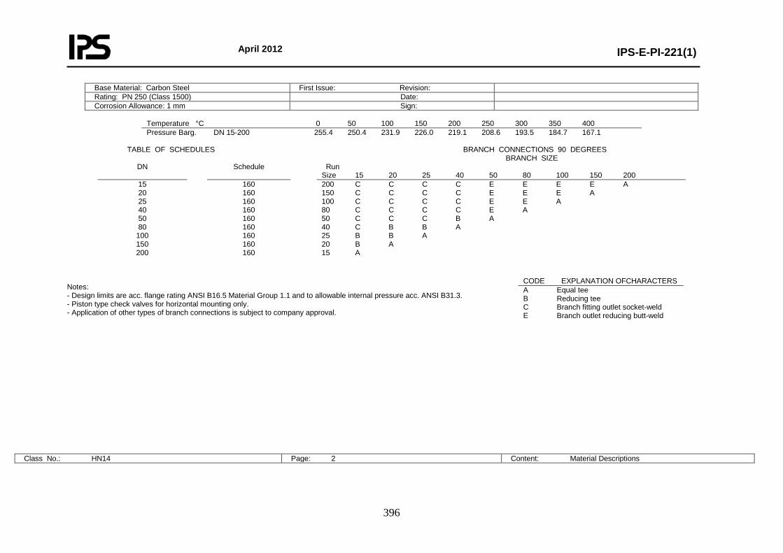
April 2012
IPS-E-PI-221(1)
396
Base Material: Carbon Steel First Issue: Revision: Rating: PN 250 (Class 1500) Date: Corrosion Allowance: 1 mm Sign:
Temperature °C 0 50 100 150 200 250 300 350 400 Pressure Barg. DN 15-200 255.4 250.4 231.9 226.0 219.1 208.6 193.5 184.7 167.1
TABLE OF SCHEDULES BRANCH CONNECTIONS 90 DEGREES BRANCH SIZE
DN Schedule Run Size 15 20 25 40 50 80 100 150 200
15 20 25 40 50 80
100 150 200
160 160 160 160 160 160 160 160 160
200 C C C C E E E E A 150 C C C C E E E A 100 C C C C E E A 80 C C C C E A 50 C C C B A 40 C B B A 25 B B A 20 B A 15 A
Notes: - Design limits are acc. flange rating ANSI B16.5 Material Group 1.1 and to allowable internal pressure acc. ANSI B31.3. - Piston type check valves for horizontal mounting only. - Application of other types of branch connections is subject to company approval.
Class No.: HN14 Page: 2 Content: Material Descriptions
CODE EXPLANATION OFCHARACTERS A Equal tee B Reducing tee C Branch fitting outlet socket-weld E Branch outlet reducing butt-weld
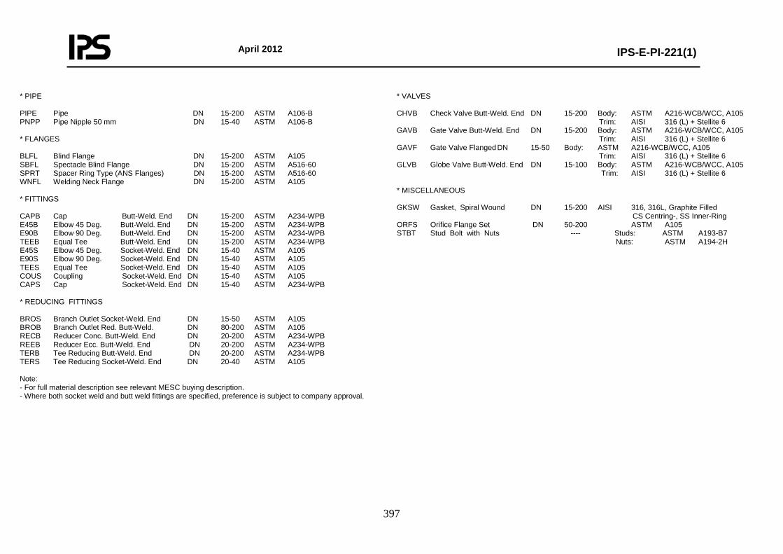
April 2012
IPS-E-PI-221(1)
397
* PIPE PIPE Pipe DN 15-200 ASTM A106-B PNPP Pipe Nipple 50 mm DN 15-40 ASTM A106-B * FLANGES BLFL Blind Flange DN 15-200 ASTM A105 SBFL Spectacle Blind Flange DN 15-200 ASTM A516-60 SPRT Spacer Ring Type (ANS Flanges) DN 15-200 ASTM A516-60 WNFL Welding Neck Flange DN 15-200 ASTM A105 * FITTINGS CAPB Cap Butt-Weld. End DN 15-200 ASTM A234-WPB E45B Elbow 45 Deg. Butt-Weld. End DN 15-200 ASTM A234-WPB E90B Elbow 90 Deg. Butt-Weld. End DN 15-200 ASTM A234-WPB TEEB Equal Tee Butt-Weld. End DN 15-200 ASTM A234-WPB E45S Elbow 45 Deg. Socket-Weld. End DN 15-40 ASTM A105 E90S Elbow 90 Deg. Socket-Weld. End DN 15-40 ASTM A105 TEES Equal Tee Socket-Weld. End DN 15-40 ASTM A105 COUS Coupling Socket-Weld. End DN 15-40 ASTM A105 CAPS Cap Socket-Weld. End DN 15-40 ASTM A234-WPB * REDUCING FITTINGS BROS Branch Outlet Socket-Weld. End DN 15-50 ASTM A105 BROB Branch Outlet Red. Butt-Weld. DN 80-200 ASTM A105 RECB Reducer Conc. Butt-Weld. End DN 20-200 ASTM A234-WPB REEB Reducer Ecc. Butt-Weld. End DN 20-200 ASTM A234-WPB TERB Tee Reducing Butt-Weld. End DN 20-200 ASTM A234-WPB TERS Tee Reducing Socket-Weld. End DN 20-40 ASTM A105 Note: - For full material description see relevant MESC buying description. - Where both socket weld and butt weld fittings are specified, preference is subject to company approval.
* VALVES CHVB Check Valve Butt-Weld. End DN 15-200 Body: ASTM A216-WCB/WCC, A105 Trim: AISI 316 (L) + Stellite 6 GAVB Gate Valve Butt-Weld. End DN 15-200 Body: ASTM A216-WCB/WCC, A105 Trim: AISI 316 (L) + Stellite 6 GAVF Gate Valve Flanged DN 15-50 Body: ASTM A216-WCB/WCC, A105 Trim: AISI 316 (L) + Stellite 6 GLVB Globe Valve Butt-Weld. End DN 15-100 Body: ASTM A216-WCB/WCC, A105 Trim: AISI 316 (L) + Stellite 6 * MISCELLANEOUS GKSW Gasket, Spiral Wound DN 15-200 AISI 316, 316L, Graphite Filled CS Centring-, SS Inner-Ring ORFS Orifice Flange Set DN 50-200 ASTM A105 STBT Stud Bolt with Nuts ---- Studs: ASTM A193-B7 Nuts: ASTM A194-2H
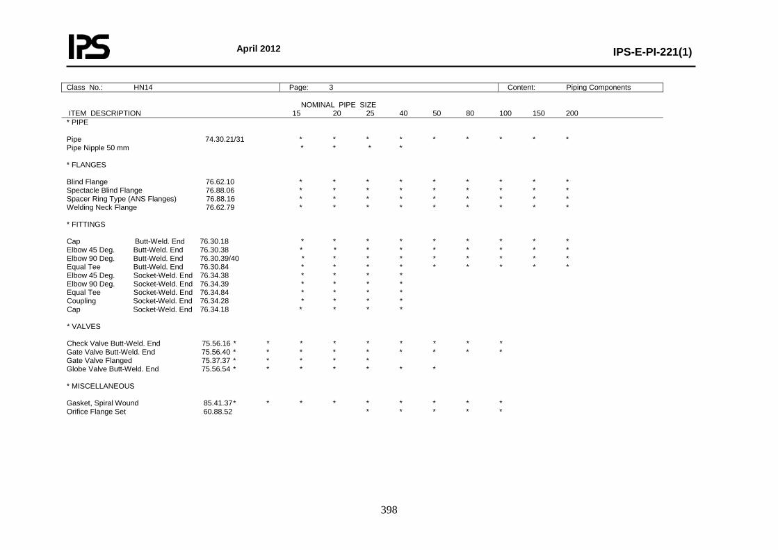
April 2012
IPS-E-PI-221(1)
398
Class No.: HN14 Page: 3 Content: Piping Components NOMINAL PIPE SIZE ITEM DESCRIPTION 15 20 25 40 50 80 100 150 200 * PIPE Pipe 74.30.21/31 * * * * * * * * * Pipe Nipple 50 mm * * * * * FLANGES Blind Flange 76.62.10 * * * * * * * * * Spectacle Blind Flange 76.88.06 * * * * * * * * * Spacer Ring Type (ANS Flanges) 76.88.16 * * * * * * * * * Welding Neck Flange 76.62.79 * * * * * * * * * * FITTINGS Cap Butt-Weld. End 76.30.18 * * * * * * * * * Elbow 45 Deg. Butt-Weld. End 76.30.38 * * * * * * * * * Elbow 90 Deg. Butt-Weld. End 76.30.39/40 * * * * * * * * * Equal Tee Butt-Weld. End 76.30.84 * * * * * * * * * Elbow 45 Deg. Socket-Weld. End 76.34.38 * * * * Elbow 90 Deg. Socket-Weld. End 76.34.39 * * * * Equal Tee Socket-Weld. End 76.34.84 * * * * Coupling Socket-Weld. End 76.34.28 * * * * Cap Socket-Weld. End 76.34.18 * * * * * VALVES Check Valve Butt-Weld. End 75.56.16 * * * * * * * * * Gate Valve Butt-Weld. End 75.56.40 * * * * * * * * * Gate Valve Flanged 75.37.37 * * * * * Globe Valve Butt-Weld. End 75.56.54 * * * * * * * * MISCELLANEOUS Gasket, Spiral Wound 85.41.37 * * * * * * * * * Orifice Flange Set 60.88.52 * * * * *
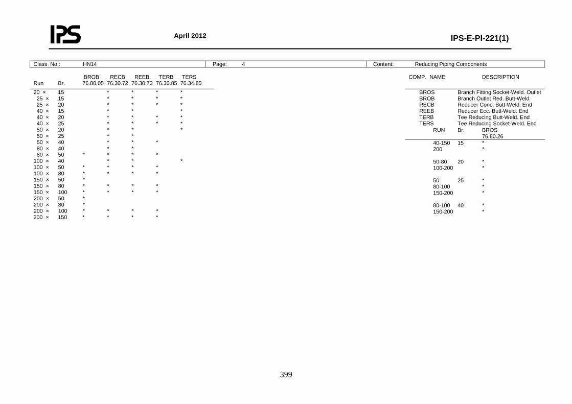
April 2012
IPS-E-PI-221(1)
399
Class No.: HN14 Page: 4 Content: Reducing Piping Components
BROB RECB REEB TERB TERS Run Br. 76.80.05 76.30.72 76.30.73 76.30.85 76.34.85
COMP. NAME DESCRIPTION
20 × 15 * * * * 25 × 15 * * * * 25 × 20 * * * * 40 × 15 * * * 40 × 20 * * * * 40 × 25 * * * * 50 × 20 * * * 50 × 25 * * 50 × 40 * * * 80 × 40 * * 80 × 50 * * * * 100 × 40 * * * 100 × 50 * * * * 100 × 80 * * * * 150 × 50 * 150 × 80 * * * * 150 × 100 * * * * 200 × 50 * 200 × 80 * 200 × 100 * * * * 200 × 150 * * * *
BROS Branch Fitting Socket-Weld. Outlet BROB Branch Outlet Red. Butt-Weld RECB Reducer Conc. Butt-Weld. End REEB Reducer Ecc. Butt-Weld. End TERB Tee Reducing Butt-Weld. End TERS Tee Reducing Socket-Weld. End
RUN Br. BROS 76.80.26
40-150 15 * 200 * 50-80 20 * 100-200 * 50 25 * 80-100 * 150-200 * 80-100 40 * 150-200 *

April 2012
IPS-E-PI-221(1)
400
Class No.: HN14 Page: 5 Content: Bolting and Assemblies
BOLT SET FLANGED JOINTS DN No. Inch mm 81.38.61
BOLT SET ORIFICE FLANGES DN No. Inch mm 81.38.61
15 4 ¾ × 110 * 20 4 ¾ × 120 * 25 4 7/8 × 130 * 40 4 1 × 140 * 50 8 7/8 × 150 * 80 8 11/8 × 180 * 100 8 11/4 × 195 * 150 12 13/8 × 260 * 200 12 15/8 × 350 *
15 4 7/8 × 150 * 20 4 7/8 × 150 * 25 4 7/8 × 150 * 40 4 1 × 160 * 50 8 7/8 × 160 * 80 8 11/8 × 190 * 100 8 11/4 × 210 * 150 12 13/8 × 275 * 200 12 15/8 × 360 *
BOLT SET SPECTACLE/SPACER DN No. Inch mm 81.38.61
15 4 ¾ × 120 * 20 4 ¾ × 130 * 25 4 7/8 × 140 * 40 4 1 × 160 * 50 8 7/8 × 170 * 80 8 11/8 × 210 * 100 8 11/4 × 230 * 150 12 13/8 × 300 * 200 12 15/8 × 400 *
DRAIN POINT Fig. 0M Run DN 15-25 Br DN 15 Run DN 40 Br DN 20 No. Branch: Table Page 1 1 Blind Flange 1 Gasket Spiral Wound 1 Gate Valve Butt-Weld Ends 1 Stud Bolt with Nuts 4 Welding Neck Flange 1 * DRAIN POINT Fig. 0N Run DN 50-200 Br DN 20 No. Branch: Table Page 1 1 Blind Flange 1 Gasket Spiral Wound 1 Gate Valve Butt-Weld Ends 1 Pipe Nipple 50 mm 1 Stud Bolt with Nuts 4 Welding Neck Flange 1 * VENT POINT Fig. 1M Run DN 15-25 Br DN 15 Run DN 40 Br DN 20 No. Branch: Table Page 1 1 Blind Flange 1 Gasket Spiral Wound 1 Globe Valve Butt-Weld Ends 1 Stud Bolt with Nuts 4 Welding Neck Flange 1 * VENT POINT Fig. 1N Run DN 50-200 Br DN 20 No. Branch: Table Page 1 1 Blind Flange 1 Gasket Spiral Wound 1 Globe Valve Butt-Weld Ends 1 Pipe Nipple 50 mm 1 Stud Bolt with Nuts 4 Welding Neck Flange 1
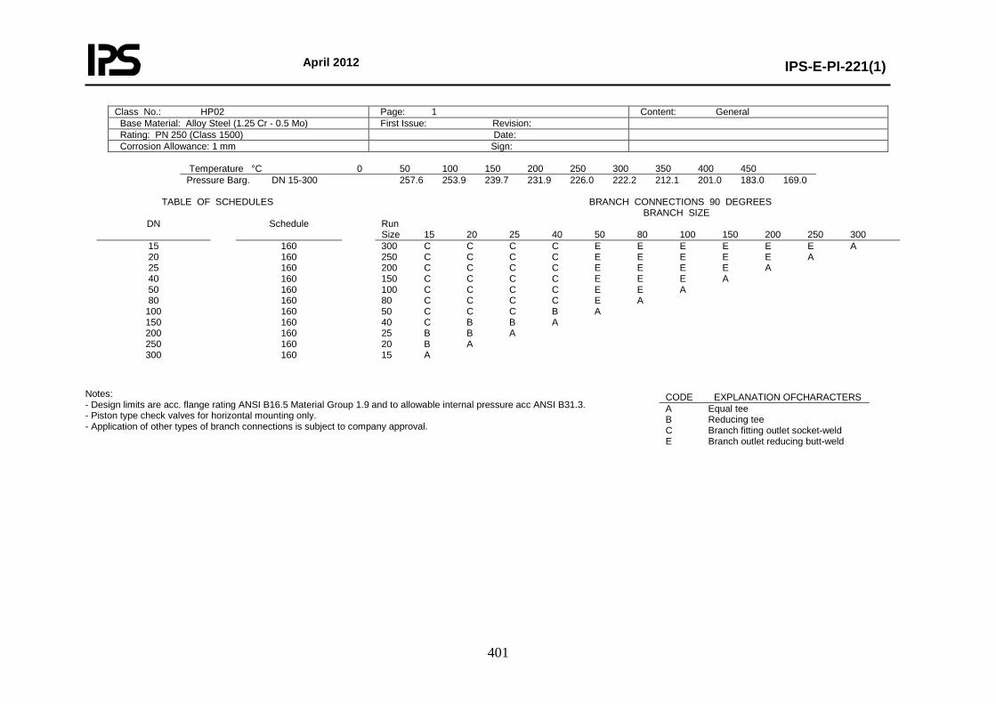
April 2012
IPS-E-PI-221(1)
401
Class No.: HP02 Page: 1 Content: General Base Material: Alloy Steel (1.25 Cr - 0.5 Mo) First Issue: Revision: Rating: PN 250 (Class 1500) Date: Corrosion Allowance: 1 mm Sign:
Temperature °C 0 50 100 150 200 250 300 350 400 450 Pressure Barg. DN 15-300 257.6 253.9 239.7 231.9 226.0 222.2 212.1 201.0 183.0 169.0
TABLE OF SCHEDULES BRANCH CONNECTIONS 90 DEGREES BRANCH SIZE
DN Schedule Run Size 15 20 25 40 50 80 100 150 200 250 300
15 20 25 40 50 80
100 150 200 250 300
160 160 160 160 160 160 160 160 160 160 160
300 C C C C E E E E E E A 250 C C C C E E E E E A 200 C C C C E E E E A 150 C C C C E E E A 100 C C C C E E A 80 C C C C E A 50 C C C B A 40 C B B A 25 B B A 20 B A 15 A
Notes: - Design limits are acc. flange rating ANSI B16.5 Material Group 1.9 and to allowable internal pressure acc ANSI B31.3. - Piston type check valves for horizontal mounting only. - Application of other types of branch connections is subject to company approval.
CODE EXPLANATION OFCHARACTERS A Equal tee B Reducing tee C Branch fitting outlet socket-weld E Branch outlet reducing butt-weld
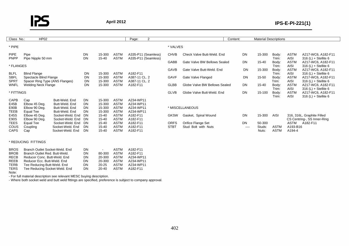
April 2012
IPS-E-PI-221(1)
402
Class No.: HP02 Page: 2 Content: Material Descriptions
* PIPE PIPE Pipe DN 15-300 ASTM A335-P11 (Seamless) PNPP Pipe Nipple 50 mm DN 15-40 ASTM A335-P11 (Seamless) * FLANGES BLFL Blind Flange DN 15-300 ASTM A182-F11 SBFL Spectacle Blind Flange DN 15-300 ASTM A387-11 CL. 2 SPRT Spacer Ring Type (ANS Flanges) DN 15-300 ASTM A387-11 CL. 2 WNFL Welding Neck Flange DN 15-300 ASTM A182-F11 * FITTINGS CAPB Cap Butt-Weld. End DN 15-300 ASTM A234-WP11 E45B Elbow 45 Deg. Butt-Weld. End DN 15-300 ASTM A234-WP11 E90B Elbow 90 Deg. Butt-Weld. End DN 15-300 ASTM A234-WP11 TEEB Equal Tee Butt-Weld. End DN 15-300 ASTM A234-WP11 E45S Elbow 45 Deg. Socket-Weld. End DN 15-40 ASTM A182-F11 E90S Elbow 90 Deg. Socket-Weld. End DN 15-40 ASTM A182-F11 TEES Equal Tee Socket-Weld. End DN 15-40 ASTM A182-F11 COUS Coupling Socket-Weld. End DN 15-40 ASTM A182-F11 CAPS Cap Socket-Weld. End DN 15-40 ASTM A182-F11 * REDUCING FITTINGS BROS Branch Outlet Socket-Weld. End DN - ASTM A182-F11 BROB Branch Outlet Red. Butt-Weld. DN 80-300 ASTM A182-F11 RECB Reducer Conc. Butt-Weld. End DN 20-300 ASTM A234-WP11 REEB Reducer Ecc. Butt-Weld. End DN 20-300 ASTM A234-WP11 TERB Tee Reducing Butt-Weld. End DN 20-25 ASTM A234-WP11 TERS Tee Reducing Socket-Weld. End DN 20-40 ASTM A182-F11 Note: - For full material description see relevant MESC buying description. - Where both socket weld and butt weld fittings are specified, preference is subject to company approval.
* VALVES CHVB Check Valve Butt-Weld. End DN 15-300 Body: ASTM A217-WC6, A182-F11 Trim: AISI 316 (L) + Stellite 6 GABB Gate Valve BW Bellows Sealed DN 15-40 Body: ASTM A217-WC6, A182-F11 Trim: AISI 316 (L) + Stellite 6 GAVB Gate Valve Butt-Weld. End DN 15-300 Body: ASTM A217-WC6, A182-F11 Trim: AISI 316 (L) + Stellite 6 GAVF Gate Valve Flanged DN 15-50 Body: ASTM A217-WC6, A182-F11 Trim: AISI 316 (L) + Stellite 6 GLBB Globe Valve BW Bellows Sealed DN 15-40 Body: ASTM A217-WC6, A182-F11 Trim: AISI 316 (L) + Stellite 6 GLVB Globe Valve Butt-Weld. End DN 15-100 Body: ASTM A217-WC6, A182-F11 Trim: AISI 316 (L) + Stellite 6 * MISCELLANEOUS GKSW Gasket, Spiral Wound DN 15-300 AISI 316, 316L, Graphite Filled CS Centring-, SS Inner-Ring ORFS Orifice Flange Set DN 50-300 ASTM A182-F11 STBT Stud Bolt with Nuts ---- Studs: ASTM A193-B16 Nuts: ASTM A194-4
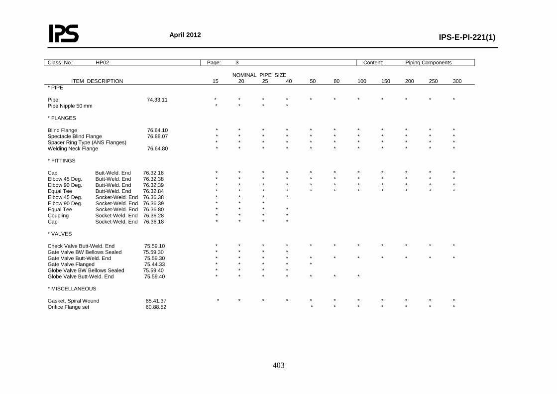
April 2012
IPS-E-PI-221(1)
403
Class No.: HP02 Page: 3 Content: Piping Components
NOMINAL PIPE SIZE ITEM DESCRIPTION 15 20 25 40 50 80 100 150 200 250 300 * PIPE Pipe 74.33.11 * * * * * * * * * * * Pipe Nipple 50 mm * * * * * FLANGES Blind Flange 76.64.10 * * * * * * * * * * * Spectacle Blind Flange 76.88.07 * * * * * * * * * * * Spacer Ring Type (ANS Flanges) * * * * * * * * * * * Welding Neck Flange 76.64.80 * * * * * * * * * * * * FITTINGS Cap Butt-Weld. End 76.32.18 * * * * * * * * * * * Elbow 45 Deg. Butt-Weld. End 76.32.38 * * * * * * * * * * * Elbow 90 Deg. Butt-Weld. End 76.32.39 * * * * * * * * * * * Equal Tee Butt-Weld. End 76.32.84 * * * * * * * * * * * Elbow 45 Deg. Socket-Weld. End 76.36.38 * * * * Elbow 90 Deg. Socket-Weld. End 76.36.39 * * * Equal Tee Socket-Weld. End 76.36.80 * * * * Coupling Socket-Weld. End 76.36.28 * * * * Cap Socket-Weld. End 76.36.18 * * * * * VALVES Check Valve Butt-Weld. End 75.59.10 * * * * * * * * * * * Gate Valve BW Bellows Sealed 75.59.30 * * * * Gate Valve Butt-Weld. End 75.59.30 * * * * * * * * * * * Gate Valve Flanged 75.44.33 * * * * * Globe Valve BW Bellows Sealed 75.59.40 * * * * Globe Valve Butt-Weld. End 75.59.40 * * * * * * * * MISCELLANEOUS Gasket, Spiral Wound 85.41.37 * * * * * * * * * * * Orifice Flange set 60.88.52 * * * * * * *
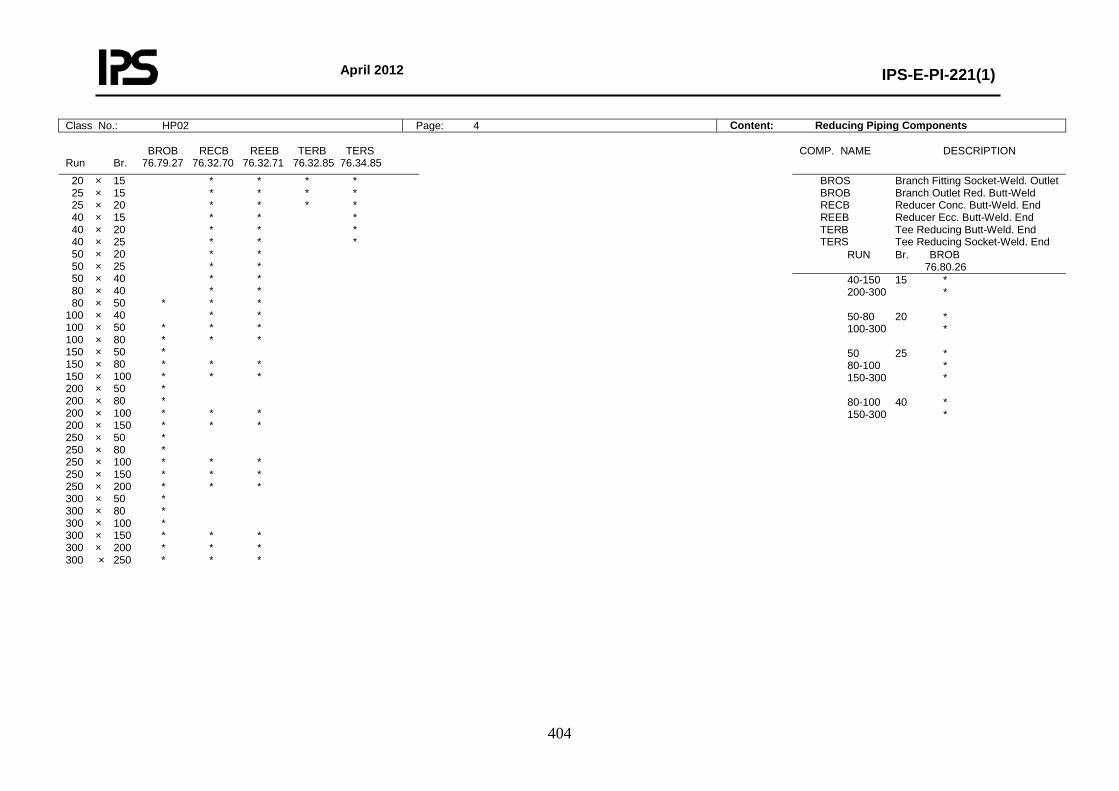
April 2012
IPS-E-PI-221(1)
404
Class No.: HP02 Page: 4 Content: Reducing Piping Components
BROB RECB REEB TERB TERS Run Br. 76.79.27 76.32.70 76.32.71 76.32.85 76.34.85
COMP. NAME DESCRIPTION
20 × 15 * * * * 25 × 15 * * * * 25 × 20 * * * * 40 × 15 * * * 40 × 20 * * * 40 × 25 * * * 50 × 20 * * 50 × 25 * * 50 × 40 * * 80 × 40 * * 80 × 50 * * * 100 × 40 * * 100 × 50 * * * 100 × 80 * * * 150 × 50 * 150 × 80 * * * 150 × 100 * * * 200 × 50 * 200 × 80 * 200 × 100 * * * 200 × 150 * * * 250 × 50 * 250 × 80 * 250 × 100 * * * 250 × 150 * * * 250 × 200 * * * 300 × 50 * 300 × 80 * 300 × 100 * 300 × 150 * * * 300 × 200 * * * 300 × 250 * * *
BROS Branch Fitting Socket-Weld. Outlet BROB Branch Outlet Red. Butt-Weld RECB Reducer Conc. Butt-Weld. End REEB Reducer Ecc. Butt-Weld. End TERB Tee Reducing Butt-Weld. End TERS Tee Reducing Socket-Weld. End
RUN Br. BROB 76.80.26
40-150 15 * 200-300 * 50-80 20 * 100-300 * 50 25 * 80-100 * 150-300 * 80-100 40 * 150-300 *
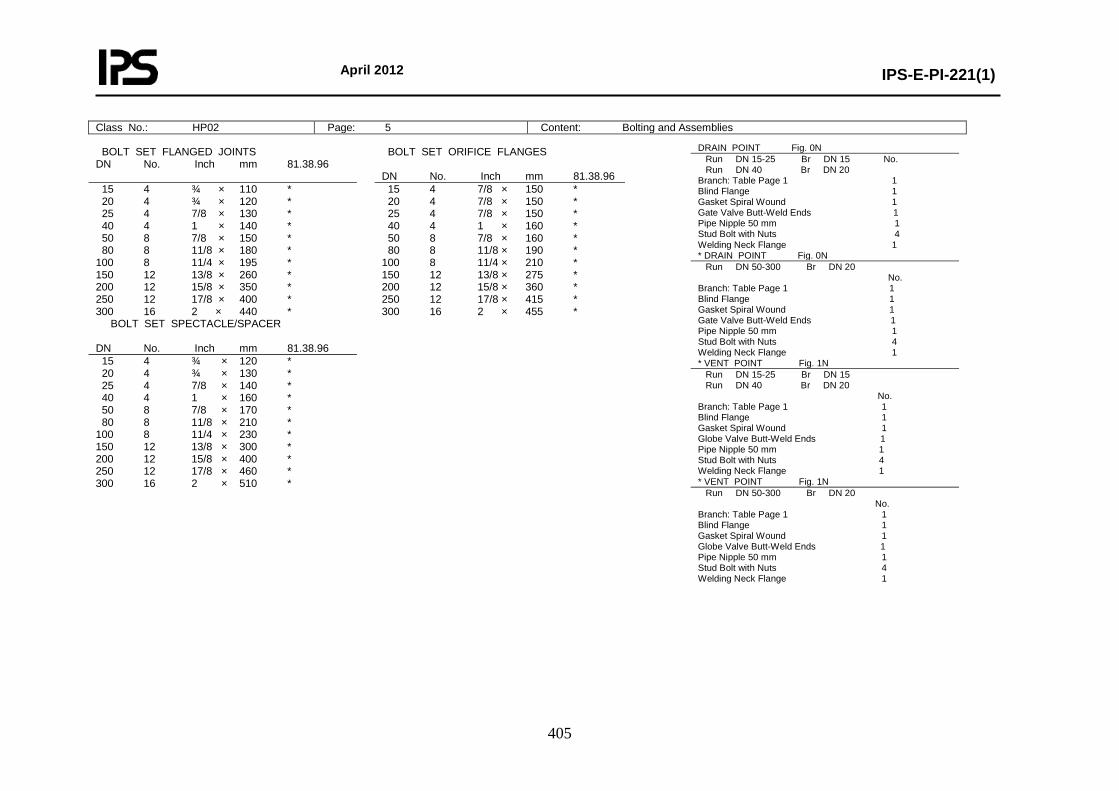
April 2012
IPS-E-PI-221(1)
405
Class No.: HP02 Page: 5 Content: Bolting and Assemblies
BOLT SET FLANGED JOINTS DN No. Inch mm 81.38.96
BOLT SET ORIFICE FLANGES DN No. Inch mm 81.38.96
15 4 ¾ × 110 * 20 4 ¾ × 120 * 25 4 7/8 × 130 * 40 4 1 × 140 * 50 8 7/8 × 150 * 80 8 11/8 × 180 * 100 8 11/4 × 195 * 150 12 13/8 × 260 * 200 12 15/8 × 350 * 250 12 17/8 × 400 * 300 16 2 × 440 *
15 4 7/8 × 150 * 20 4 7/8 × 150 * 25 4 7/8 × 150 * 40 4 1 × 160 * 50 8 7/8 × 160 * 80 8 11/8 × 190 * 100 8 11/4 × 210 * 150 12 13/8 × 275 * 200 12 15/8 × 360 * 250 12 17/8 × 415 * 300 16 2 × 455 *
BOLT SET SPECTACLE/SPACER DN No. Inch mm 81.38.96
15 4 ¾ × 120 * 20 4 ¾ × 130 * 25 4 7/8 × 140 * 40 4 1 × 160 * 50 8 7/8 × 170 * 80 8 11/8 × 210 * 100 8 11/4 × 230 * 150 12 13/8 × 300 * 200 12 15/8 × 400 * 250 12 17/8 × 460 * 300 16 2 × 510 *
DRAIN POINT Fig. 0N Run DN 15-25 Br DN 15 No. Run DN 40 Br DN 20 Branch: Table Page 1 1 Blind Flange 1 Gasket Spiral Wound 1 Gate Valve Butt-Weld Ends 1 Pipe Nipple 50 mm 1 Stud Bolt with Nuts 4 Welding Neck Flange 1 * DRAIN POINT Fig. 0N Run DN 50-300 Br DN 20 No. Branch: Table Page 1 1 Blind Flange 1 Gasket Spiral Wound 1 Gate Valve Butt-Weld Ends 1 Pipe Nipple 50 mm 1 Stud Bolt with Nuts 4 Welding Neck Flange 1 * VENT POINT Fig. 1N Run DN 15-25 Br DN 15 Run DN 40 Br DN 20 No. Branch: Table Page 1 1 Blind Flange 1 Gasket Spiral Wound 1 Globe Valve Butt-Weld Ends 1 Pipe Nipple 50 mm 1 Stud Bolt with Nuts 4 Welding Neck Flange 1 * VENT POINT Fig. 1N Run DN 50-300 Br DN 20 No. Branch: Table Page 1 1 Blind Flange 1 Gasket Spiral Wound 1 Globe Valve Butt-Weld Ends 1 Pipe Nipple 50 mm 1 Stud Bolt with Nuts 4 Welding Neck Flange 1
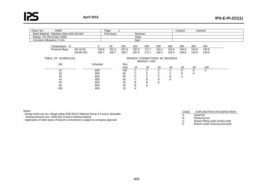
April 2012
IPS-E-PI-221(1)
406
Class No.: HS06 Page: 1 Content: General Base Material: Stainless Steel AISI 321/347 First Issue: Revision: Rating: PN 250 (Class 1500) Date: Corrosion Allowance: 0 mm Sign:
Temperature °C 0 50 100 150 200 250 300 350 400 450 Pressure Barg. DN 15-50 236.8 231.0 207.6 187.5 171.7 160.1 152.6 146.6 143.0 140.9 DN 80-100 190.7 190.7 190.7 187.5 171.7 160.1 152.6 146.6 143.0 140.9
TABLE OF SCHEDULES BRANCH CONNECTIONS 90 DEGREES BRANCH SIZE
DN Schedule Run Size 15 20 25 40 50 80 100
15 20 25 40 50 80
100
80S 80S 80S 80S 80S 80S 80S
100 C C C C E E A 80 C C C C E A 50 C C C B A 40 C B B A 25 B B A 20 B A 15 A
Notes: - Design limits are acc. flange rating ANSI B16.5 Material Group 2.4 and to allowable internal pressure acc. ANSI B31.3 and to bolting material. - Application of other types of branch connections is subject to company approval.
CODE EXPLANATION OFCHARACTERS A Equal tee B Reducing tee C Branch fitting outlet socket-weld E Branch outlet reducing butt-weld

April 2012
IPS-E-PI-221(1)
407
Class No.: HS06 Page: 2 Content: Material Descriptions
* PIPE PIPE Pipe DN 15-100 ASTM A312-TP321/347 (Seamless or Welded) PNPP Pipe Nipple 50 mm DN 15-40 ASTM A312-TP321/347 (Seamless) * FLANGES BLFL Blind Flange DN 15-100 ASTM A182-F321/347 SBFL Spectacle Blind Flange DN 15-100 ASTM A240-TP321/347 SPRT Spacer Ring Type (ANS Flanges) DN 15-100 ASTM A240-TP321/347 WNFL Welding Neck Flange DN 15-100 ASTM A182-F321/347 * FITTINGS CAPB Cap Butt-Weld. End DN 15-100 ASTM A403-WP321/347 E45B Elbow 45 Deg. Butt-Weld. End DN 15-100 ASTM A403-WP321/347 E90B Elbow 90 Deg. Butt-Weld. End DN 15-100 ASTM A403-WP321/347 TEEB Equal Tee Butt-Weld. End DN 15-100 ASTM A403-WP321/347 E45S Elbow 45 Deg. Socket-Weld. End DN 15-40 ASTM A182-F321/347 E90S Elbow 90 Deg. Socket-Weld. End DN 15-40 ASTM A182-F321/347 TEES Equal Tee Socket-Weld. End DN 15-40 ASTM A182-F321/347 COUS Coupling Socket-Weld. End DN 15-40 ASTM A182-F321/347 CAPS Cap Socket-Weld. End DN 15-40 ASTM A182-F321/347 * REDUCING FITTINGS BROS Branch Outlet Socket-Weld. End DN 15-50 ASTM A182-F321/347 BROB Branch Outlet Red. Butt-Weld. DN 80-100 ASTM A182-F321/347 RECB Reducer Conc. Butt-Weld. End DN 20-100 ASTM A403-WP321/347 REEB Reducer Ecc. Butt-Weld. End DN 20-100 ASTM A403-WP321/347 TERB Tee Reducing Butt-Weld. End DN 20-50 ASTM A403-WP321/347 TERS Tee Reducing Socket-Weld. End DN 20-40 ASTM A182-F321/347 Note: - For full material description see relevant MESC buying description. - Where both socket weld and butt weld fittings are specified, preference is subject to company approval.
* VALVES CHVF Check Valve Flanged DN 15-100 Body: ASTM A351-CF8C, A182-F321 Trim: AISI 321 GAVF Gate Valve Flanged DN 15-100 Body: ASTM A351-CF8C, A182-F321 Trim: AISI 321 GLVF Globe Valve Flanged DN 15-100 Body: ASTM A351-CF8C, A182-F321 Trim: AISI 321 * MISCELLANEOUS GKSW Gasket, Spiral Wound DN 15-100 AISI 316, 316L, Graphite Filled CS Centring-, SS Inner-Ring ORFS Orifice Flange Set DN 50-100 ASTM A182-F321/347 STBT Stud Bolt with Nuts --- ASTM A453-Gr. 660, CL.
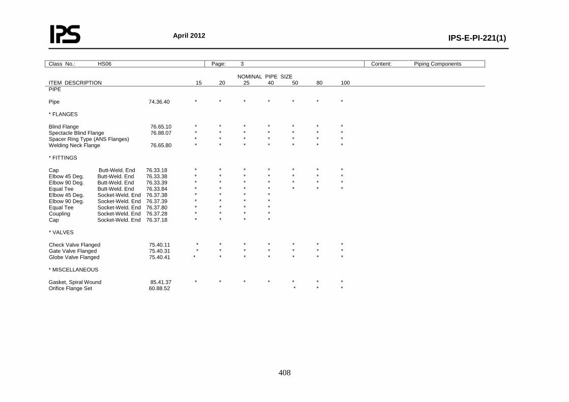
April 2012
IPS-E-PI-221(1)
408
Class No.: HS06 Page: 3 Content: Piping Components
NOMINAL PIPE SIZE ITEM DESCRIPTION 15 20 25 40 50 80 100 PIPE Pipe 74.36.40 * * * * * * * * FLANGES Blind Flange 76.65.10 * * * * * * * Spectacle Blind Flange 76.88.07 * * * * * * * Spacer Ring Type (ANS Flanges) * * * * * * * Welding Neck Flange 76.65.80 * * * * * * * * FITTINGS Cap Butt-Weld. End 76.33.18 * * * * * * * Elbow 45 Deg. Butt-Weld. End 76.33.38 * * * * * * * Elbow 90 Deg. Butt-Weld. End 76.33.39 * * * * * * * Equal Tee Butt-Weld. End 76.33.84 * * * * * * * Elbow 45 Deg. Socket-Weld. End 76.37.38 * * * * Elbow 90 Deg. Socket-Weld. End 76.37.39 * * * * Equal Tee Socket-Weld. End 76.37.80 * * * * Coupling Socket-Weld. End 76.37.28 * * * * Cap Socket-Weld. End 76.37.18 * * * * * VALVES Check Valve Flanged 75.40.11 * * * * * * * Gate Valve Flanged 75.40.31 * * * * * * * Globe Valve Flanged 75.40.41 * * * * * * * * MISCELLANEOUS Gasket, Spiral Wound 85.41.37 * * * * * * * Orifice Flange Set 60.88.52 * * *
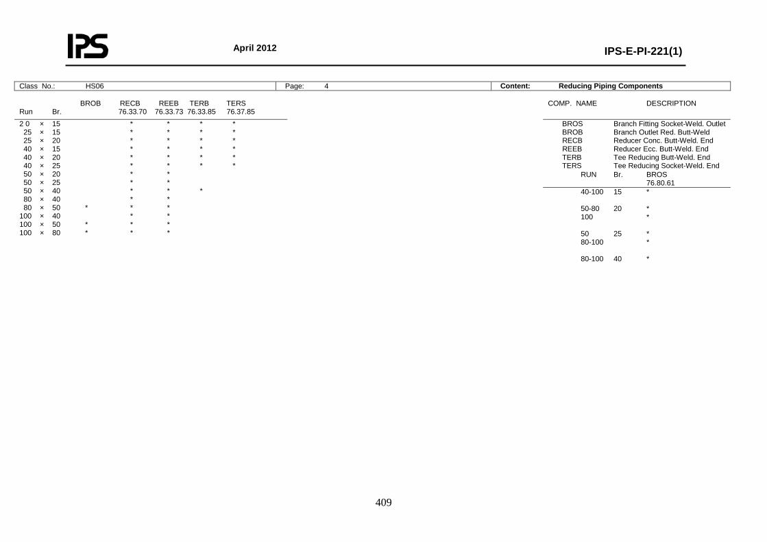
April 2012
IPS-E-PI-221(1)
409
Class No.: HS06 Page: 4 Content: Reducing Piping Components
BROB RECB REEB TERB TERS Run Br. 76.33.70 76.33.73 76.33.85 76.37.85
COMP. NAME DESCRIPTION
2 0 × 15 * * * * 25 × 15 * * * * 25 × 20 * * * * 40 × 15 * * * * 40 × 20 * * * * 40 × 25 * * * * 50 × 20 * * 50 × 25 * * 50 × 40 * * * 80 × 40 * * 80 × 50 * * * 100 × 40 * * 100 × 50 * * * 100 × 80 * * *
BROS Branch Fitting Socket-Weld. Outlet BROB Branch Outlet Red. Butt-Weld RECB Reducer Conc. Butt-Weld. End REEB Reducer Ecc. Butt-Weld. End TERB Tee Reducing Butt-Weld. End TERS Tee Reducing Socket-Weld. End
RUN Br. BROS 76.80.61
40-100 15 * 50-80 20 * 100 * 50 25 * 80-100 * 80-100 40 *
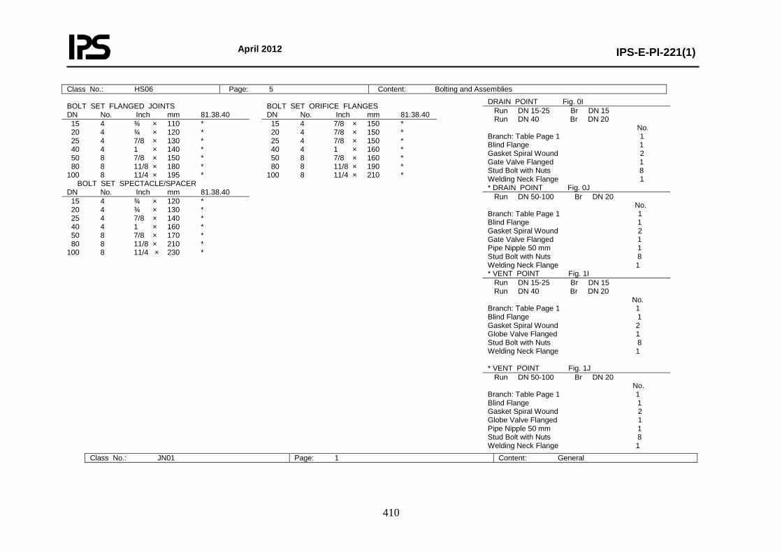
April 2012
IPS-E-PI-221(1)
410
Class No.: JN01 Page: 1 Content: General
Class No.: HS06 Page: 5 Content: Bolting and Assemblies
BOLT SET FLANGED JOINTS DN No. Inch mm 81.38.40
BOLT SET ORIFICE FLANGES DN No. Inch mm 81.38.40
15 4 ¾ × 110 * 20 4 ¾ × 120 * 25 4 7/8 × 130 * 40 4 1 × 140 * 50 8 7/8 × 150 * 80 8 11/8 × 180 * 100 8 11/4 × 195 *
15 4 7/8 × 150 * 20 4 7/8 × 150 * 25 4 7/8 × 150 * 40 4 1 × 160 * 50 8 7/8 × 160 * 80 8 11/8 × 190 * 100 8 11/4 × 210 *
BOLT SET SPECTACLE/SPACER DN No. Inch mm 81.38.40
15 4 ¾ × 120 * 20 4 ¾ × 130 * 25 4 7/8 × 140 * 40 4 1 × 160 * 50 8 7/8 × 170 * 80 8 11/8 × 210 * 100 8 11/4 × 230 *
DRAIN POINT Fig. 0I Run DN 15-25 Br DN 15 Run DN 40 Br DN 20 No. Branch: Table Page 1 1 Blind Flange 1 Gasket Spiral Wound 2 Gate Valve Flanged 1 Stud Bolt with Nuts 8 Welding Neck Flange 1 * DRAIN POINT Fig. 0J Run DN 50-100 Br DN 20 No. Branch: Table Page 1 1 Blind Flange 1 Gasket Spiral Wound 2 Gate Valve Flanged 1 Pipe Nipple 50 mm 1 Stud Bolt with Nuts 8 Welding Neck Flange 1 * VENT POINT Fig. 1I Run DN 15-25 Br DN 15 Run DN 40 Br DN 20 No. Branch: Table Page 1 1 Blind Flange 1 Gasket Spiral Wound 2 Globe Valve Flanged 1 Stud Bolt with Nuts 8 Welding Neck Flange 1 * VENT POINT Fig. 1J Run DN 50-100 Br DN 20 No. Branch: Table Page 1 1 Blind Flange 1 Gasket Spiral Wound 2 Globe Valve Flanged 1 Pipe Nipple 50 mm 1 Stud Bolt with Nuts 8 Welding Neck Flange 1
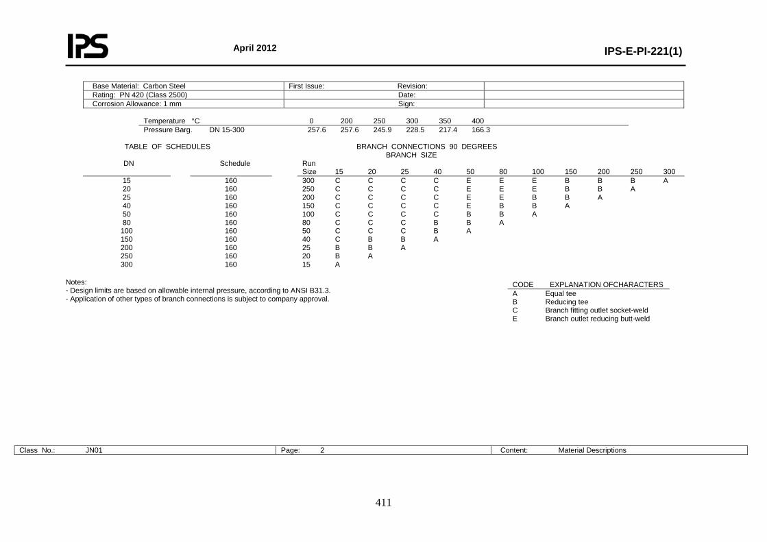
April 2012
IPS-E-PI-221(1)
411
Base Material: Carbon Steel First Issue: Revision: Rating: PN 420 (Class 2500) Date: Corrosion Allowance: 1 mm Sign:
Temperature °C 0 200 250 300 350 400 Pressure Barg. DN 15-300 257.6 257.6 245.9 228.5 217.4 166.3
TABLE OF SCHEDULES BRANCH CONNECTIONS 90 DEGREES BRANCH SIZE
DN Schedule Run Size 15 20 25 40 50 80 100 150 200 250 300
15 20 25 40 50 80
100 150 200 250 300
160 160 160 160 160 160 160 160 160 160 160
300 C C C C E E E B B B A 250 C C C C E E E B B A 200 C C C C E E B B A 150 C C C C E B B A 100 C C C C B B A 80 C C C B B A 50 C C C B A 40 C B B A 25 B B A 20 B A 15 A
Notes: - Design limits are based on allowable internal pressure, according to ANSI B31.3. - Application of other types of branch connections is subject to company approval.
Class No.: JN01 Page: 2 Content: Material Descriptions
CODE EXPLANATION OFCHARACTERS A Equal tee B Reducing tee C Branch fitting outlet socket-weld E Branch outlet reducing butt-weld
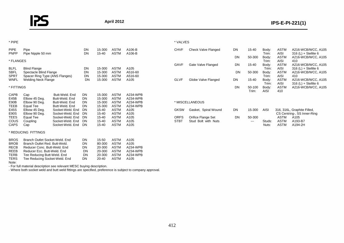
April 2012
IPS-E-PI-221(1)
412
* PIPE PIPE Pipe DN 15-300 ASTM A106-B PNPP Pipe Nipple 50 mm DN 15-40 ASTM A106-B * FLANGES BLFL Blind Flange DN 15-300 ASTM A105 SBFL Spectacle Blind Flange DN 15-300 ASTM A516-60 SPRT Spacer Ring Type (ANS Flanges) DN 15-300 ASTM A516-60 WNFL Welding Neck Flange DN 15-300 ASTM A105 * FITTINGS CAPB Cap Butt-Weld. End DN 15-300 ASTM A234-WPB E45B Elbow 45 Deg. Butt-Weld. End DN 15-300 ASTM A234-WPB E90B Elbow 90 Deg. Butt-Weld. End DN 15-300 ASTM A234-WPB TEEB Equal Tee Butt-Weld. End DN 15-300 ASTM A234-WPB E45S Elbow 45 Deg. Socket-Weld. End DN 15-40 ASTM A105 E90S Elbow 90 Deg. Socket-Weld. End DN 15-40 ASTM A105 TEES Equal Tee Socket-Weld. End DN 15-40 ASTM A105 COUS Coupling Socket-Weld. End DN 15-40 ASTM A105 CAPS Cap Socket-Weld. End DN 15-40 ASTM A105 * REDUCING FITTINGS BROS Branch Outlet Socket-Weld. End DN 15-50 ASTM A105 BROB Branch Outlet Red. Butt-Weld. DN 80-300 ASTM A105 RECB Reducer Conc. Butt-Weld. End DN 20-300 ASTM A234-WPB REEB Reducer Ecc. Butt-Weld. End DN 20-300 ASTM A234-WPB TERB Tee Reducing Butt-Weld. End DN 20-300 ASTM A234-WPB TERS Tee Reducing Socket-Weld. End DN 20-40 ASTM A105 Note: - For full material description see relevant MESC buying description. - Where both socket weld and butt weld fittings are specified, preference is subject to company approval.
* VALVES CHVF Check Valve Flanged DN 15-40 Body: ASTM A216-WCB/WCC, A105 Trim: AISI 316 (L) + Stellite 6 DN 50-300 Body: ASTM A216-WCB/WCC, A105 Trim: AISI 410 GAVF Gate Valve Flanged DN 15-40 Body: ASTM A216-WCB/WCC, A105 Trim: AISI 316 (L) + Stellite 6 DN 50-300 Body: ASTM A216-WCB/WCC, A105 Trim: AISI 410 GLVF Globe Valve Flanged DN 15-40 Body: ASTM A216-WCB/WCC, A105 Trim: AISI 316 (L) + Stellite 6 DN 50-100 Body: ASTM A216-WCB/WCC, A105 Trim: AISI 410 * MISCELLANEOUS GKSW Gasket, Spiral Wound DN 15-300 AISI 316, 316L, Graphite Filled, CS Centring-, SS Inner-Ring ORFS Orifice Flange Set DN 50-300 ASTM A105 STBT Stud Bolt with Nuts --- Studs: ASTM A193-B7 Nuts: ASTM A194-2H
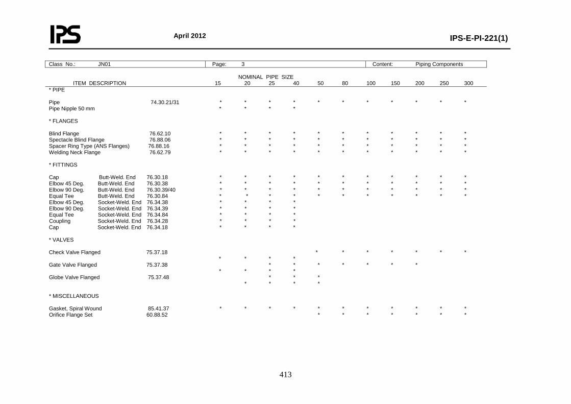
April 2012
IPS-E-PI-221(1)
413
Class No.: JN01 Page: 3 Content: Piping Components
NOMINAL PIPE SIZE ITEM DESCRIPTION 15 20 25 40 50 80 100 150 200 250 300 * PIPE Pipe 74.30.21/31 * * * * * * * * * * * Pipe Nipple 50 mm * * * * * FLANGES Blind Flange 76.62.10 * * * * * * * * * * * Spectacle Blind Flange 76.88.06 * * * * * * * * * * * Spacer Ring Type (ANS Flanges) 76.88.16 * * * * * * * * * * * Welding Neck Flange 76.62.79 * * * * * * * * * * * * FITTINGS Cap Butt-Weld. End 76.30.18 * * * * * * * * * * * Elbow 45 Deg. Butt-Weld. End 76.30.38 * * * * * * * * * * * Elbow 90 Deg. Butt-Weld. End 76.30.39/40 * * * * * * * * * * * Equal Tee Butt-Weld. End 76.30.84 * * * * * * * * * * * Elbow 45 Deg. Socket-Weld. End 76.34.38 * * * * Elbow 90 Deg. Socket-Weld. End 76.34.39 * * * * Equal Tee Socket-Weld. End 76.34.84 * * * * Coupling Socket-Weld. End 76.34.28 * * * * Cap Socket-Weld. End 76.34.18 * * * * * VALVES Check Valve Flanged 75.37.18 * * * * * * * * * * * Gate Valve Flanged 75.37.38 * * * * * * * * * * * Globe Valve Flanged 75.37.48 * * * * * * * * MISCELLANEOUS Gasket, Spiral Wound 85.41.37 * * * * * * * * * * * Orifice Flange Set 60.88.52 * * * * * * *
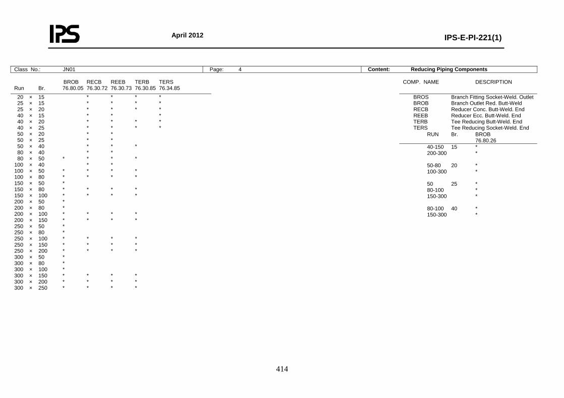
April 2012
IPS-E-PI-221(1)
414
Class No.: JN01 Page: 4 Content: Reducing Piping Components
BROB RECB REEB TERB TERS Run Br. 76.80.05 76.30.72 76.30.73 76.30.85 76.34.85
COMP. NAME DESCRIPTION
20 × 15 * * * * 25 × 15 * * * * 25 × 20 * * * * 40 × 15 * * * 40 × 20 * * * * 40 × 25 * * * * 50 × 20 * * 50 × 25 * * 50 × 40 * * * 80 × 40 * * 80 × 50 * * * * 100 × 40 * * 100 × 50 * * * * 100 × 80 * * * * 150 × 50 * 150 × 80 * * * * 150 × 100 * * * * 200 × 50 * 200 × 80 * 200 × 100 * * * * 200 × 150 * * * * 250 × 50 * 250 × 80 * 250 × 100 * * * * 250 × 150 * * * * 250 × 200 * * * * 300 × 50 * 300 × 80 * 300 × 100 * 300 × 150 * * * * 300 × 200 * * * * 300 × 250 * * * *
BROS Branch Fitting Socket-Weld. Outlet BROB Branch Outlet Red. Butt-Weld RECB Reducer Conc. Butt-Weld. End REEB Reducer Ecc. Butt-Weld. End TERB Tee Reducing Butt-Weld. End TERS Tee Reducing Socket-Weld. End
RUN Br. BROB 76.80.26
40-150 15 * 200-300 * 50-80 20 * 100-300 * 50 25 * 80-100 * 150-300 * 80-100 40 * 150-300 *
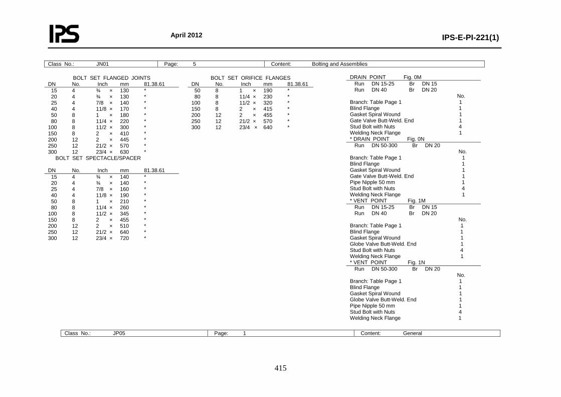
April 2012
IPS-E-PI-221(1)
415
Class No.: JP05 Page: 1 Content: General
Class No.: JN01 Page: 5 Content: Bolting and Assemblies
BOLT SET FLANGED JOINTS DN No. Inch mm 81.38.61
BOLT SET ORIFICE FLANGES DN No. Inch mm 81.38.61
15 4 ¾ × 130 * 20 4 ¾ × 130 * 25 4 7/8 × 140 * 40 4 11/8 × 170 * 50 8 1 × 180 * 80 8 11/4 × 220 * 100 8 11/2 × 300 * 150 8 2 × 410 * 200 12 2 × 445 * 250 12 21/2 × 570 * 300 12 23/4 × 630 *
50 8 1 × 190 * 80 8 11/4 × 230 * 100 8 11/2 × 320 * 150 8 2 × 415 * 200 12 2 × 455 * 250 12 21/2 × 570 * 300 12 23/4 × 640 *
BOLT SET SPECTACLE/SPACER DN No. Inch mm 81.38.61
15 4 ¾ × 140 * 20 4 ¾ × 140 * 25 4 7/8 × 160 * 40 4 11/8 × 190 * 50 8 1 × 210 * 80 8 11/4 × 260 * 100 8 11/2 × 345 * 150 8 2 × 455 * 200 12 2 × 510 * 250 12 21/2 × 640 * 300 12 23/4 × 720 *
DRAIN POINT Fig. 0M Run DN 15-25 Br DN 15 Run DN 40 Br DN 20 No. Branch: Table Page 1 1 Blind Flange 1 Gasket Spiral Wound 1 Gate Valve Butt-Weld. End 1 Stud Bolt with Nuts 4 Welding Neck Flange 1 * DRAIN POINT Fig. 0N Run DN 50-300 Br DN 20 No. Branch: Table Page 1 1 Blind Flange 1 Gasket Spiral Wound 1 Gate Valve Butt-Weld. End 1 Pipe Nipple 50 mm 1 Stud Bolt with Nuts 4 Welding Neck Flange 1 * VENT POINT Fig. 1M Run DN 15-25 Br DN 15 Run DN 40 Br DN 20 No. Branch: Table Page 1 1 Blind Flange 1 Gasket Spiral Wound 1 Globe Valve Butt-Weld. End 1 Stud Bolt with Nuts 4 Welding Neck Flange 1 * VENT POINT Fig. 1N Run DN 50-300 Br DN 20 No. Branch: Table Page 1 1 Blind Flange 1 Gasket Spiral Wound 1 Globe Valve Butt-Weld. End 1 Pipe Nipple 50 mm 1 Stud Bolt with Nuts 4 Welding Neck Flange 1
April 2012
IPS-E-PI-221(1)
416
Base Material: Alloy Steel (2.25 Cr, 1.0 Mo) First Issue: Revision: Rating: PN 420 (Class 2500) Date: Corrosion Allowance: 1 mm Sign:
Temperature °C 0 100 150 200 400 450 500 538 Pressure Barg. DN 15-300 257.6 237.5 231.8 230.6 230.5 193.5 148.4 100.1
TABLE OF SCHEDULES BRANCH CONNECTIONS 90 DEGREES BRANCH SIZE
DN Schedule Run Size 15 20 25 40 50 80 100 150 200 250 300
15 20 25 40 50 80
100 150 200 250 300
160 160 160 160 160 160 160 160 160 160 160
300 C C C C E E E B B B A 250 C C C C E E E B B A 200 C C C C E E B B A 150 C C C C E B B A 100 C C C C B B A 80 C C C B B A 50 C C C B A 40 C B B A 25 B B A 20 B A 15 A
Notes: - Design limits are based on allowable internal pressure, according to ANSI B31.3. - For temperature points a branch outlet (DN 50) shall be used for nominal pipe sizes DN 80 and above. - Bolt diameter limited to 2 inch. - Piston type check valves for horizontal mounting only. - Application of other types of branch connections is subject to company approval.
Class No.: JP05 Page: 2 Content: Material Descriptions
CODE EXPLANATION OFCHARACTERS A Equal tee B Reducing tee C Branch fitting outlet socket-weld E Branch outlet reducing butt-weld
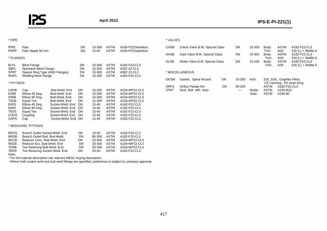
April 2012
IPS-E-PI-221(1)
417
* PIPE PIPE Pipe DN 15-300 ASTM A335-P22 Seamless PNPP Pipe Nipple 50 mm DN 15-40 ASTM A335-P22 Seamless * FLANGES BLFL Blind Flange DN 15-300 ASTM A182-F22-CL3 SBFL Spectacle Blind Flange DN 15-300 ASTM A387-22-CL2 SPRT Spacer Ring Type (ANS Flanges) DN 15-300 ASTM A387-22-CL2 WNFL Welding Neck Flange DN 15-300 ASTM A182-F22-CL3 * FITTINGS CAPB Cap Butt-Weld. End DN 15-300 ASTM A234-WP22-CL3 E45B Elbow 45 Deg. Butt-Weld. End DN 15-300 ASTM A234-WP22-CL3 E90B Elbow 90 Deg. Butt-Weld. End DN 15-300 ASTM A234-WP22-CL3 TEEB Equal Tee Butt-Weld. End DN 15-300 ASTM A234-WP22-CL3 E45S Elbow 45 Deg. Socket-Weld. End DN 15-40 ASTM A182-F22-CL3 E90S Elbow 90 Deg. Socket-Weld. End DN 15-40 ASTM A182-F22-CL3 TEES Equal Tee Socket-Weld. End DN 15-40 ASTM A182-F22-CL3 COUS Coupling Socket-Weld. End DN 15-40 ASTM A182-F22-CL3 CAPS Cap Socket-Weld. End DN 15-40 ASTM A182-F22-CL3 * REDUCING FITTINGS BROS Branch Outlet Socket-Weld. End DN 15-50 ASTM A182-F22-CL3 BROB Branch Outlet Red. Butt-Weld. DN 80-300 ASTM A182-F22-CL3 RECB Reducer Conc. Butt-Weld. End DN 20-300 ASTM A234-WP22-CL3 REEB Reducer Ecc. Butt-Weld. End DN 20-300 ASTM A234-WP22-CL3 TERB Tee Reducing Butt-Weld. End DN 20-300 ASTM A234-WP22-CL3 TERS Tee Reducing Socket-Weld. End DN 20-40 ASTM A182-F22-CL3 Note: - For full material description see relevant MESC buying description. - Where both socket weld and butt weld fittings are specified, preference is subject to company approval.
* VALVES CHSB Check Valve B.W. Special Class DN 15-300 Body: ASTM A182-F22-CL3 Trim: AISI 316 (L) + Stellite 6 GASB Gate Valve B.W. Special Class DN 15-300 Body: ASTM A182-F22-CL3 Trim: AISI 316 (L) + Stellite 6 GLSB Globe Valve B.W. Special Class DN 15-100 Body: ASTM A182-F22-CL3 Trim: AISI 316 (L) + Stellite 6 * MISCELLANEOUS GKSW Gasket, Spiral Wound DN 15-300 AISI 316, 316L, Graphite Filled, CS Centring-, SS Inner-Ring ORFS Orifice Flange Set DN 50-200 ASTM A182-F22-CL3 STBT Stud Bolt with Nuts --- Studs: ASTM A193-B16 Nuts: ASTM A194-8C
April 2012
IPS-E-PI-221(1)
418
Class No.: JP05 Page: 3 Content: Piping Components
NOMINAL PIPE SIZE ITEM DESCRIPTION 15 20 25 40 50 80 100 150 200 250 300 * PIPE Pipe 74.33.21 * * * * * * * * * * * Pipe Nipple 50 mm * * * * * FLANGES Blind Flange 76.64.12 * * * * * * * * * * * Spectacle Blind Flange 76.88.07 * * * * * * * * * * * Spacer Ring Type (ANS Flanges) * * * * * * * * * * * Welding Neck Flange 76.64.82 * * * * * * * * * * * * FITTINGS Cap Butt-Weld. End 76.32.18 * * * * * * * * * * * Elbow 45 Deg. Butt-Weld. End 76.32.38 * * * * * * * * * * * Elbow 90 Deg. Butt-Weld. End 76.32.39/40 * * * * * * * * * * * Equal Tee Butt-Weld. End 76.32.84 * * * * * * * * * * * Elbow 45 Deg. Socket-Weld. End 76.36.38 * * * * Elbow 90 Deg. Socket-Weld. End 76.36.39 * * * * Equal Tee Socket-Weld. End 76.36.80 * * * * Coupling Socket-Weld. End 76.36.28 * * * * Cap Socket-Weld. End 76.36.18 * * * * * VALVES Check Valve BW. Special Class 75.59.10 * * * * * * * * * * * Gate Valve BW. Special Class 75.59.30 * * * * * * * * * * * Globe Valve BW. Special Class 75.59.40 * * * * * * * * MISCELLANEOUS Gasket, Spiral Wound 85.41.37 * * * * * * * * * * * Orifice Flange Set 60.88.52 * * * * *
April 2012
IPS-E-PI-221(1)
419
Class No.: JP05 Page: 4 Content: Reducing Piping Components
BROB RECB REEB TERB TERS Run Br. 76.80.10 76.32.70 76.32.71 76.32.85 76.36.85
COMP. NAME DESCRIPTION
20 × 15 * * * * 25 × 15 * * * * 25 × 20 * * * * 40 × 15 * * * * 40 × 20 * * * * 40 × 25 * * * * 50 × 20 * * * 50 × 25 * * * 50 × 40 * * * 80 × 40 * * * 80 × 50 * * * * 100 × 40 * * 100 × 50 * * * 100 × 80 * * * * 150 × 50 * 150 × 80 * * * * 150 × 100 * * * * 200 × 50 * 200 × 80 * 200 × 100 * * * * 200 × 150 * * * * 250 × 50 * 250 × 80 * 250 × 100 * * * * 250 × 150 * * * * 250 × 200 * * * * 300 × 50 * 300 × 80 * 300 × 100 * 300 × 150 * * * * 300 × 200 * * * * 300 × 250 * * * *
BROS Branch Fitting Socket-Weld. Outlet BROB Branch Outlet Red. Butt-Weld RECB Reducer Conc. Butt-Weld. End REEB Reducer Ecc. Butt-Weld. End TERB Tee Reducing Butt-Weld. End TERS Tee Reducing Socket-Weld. End
RUN Br. BROS 76.83.43
40-150 15 * 200-300 * 50-80 20 * 100-300 * 50 25 * 80-100 * 150-300 * 80-100 40 * 150-300 *
April 2012
IPS-E-PI-221(1)
420
Class No.: JP05 Page: 5 Content: Bolting and Assemblies
BOLT SET FLANGED JOINTS DN No. Inch mm 81.38.96
BOLT SET ORIFICE FLANGES DN No. Inch mm 81.38.96
15 4 ¾ × 130 * 20 4 ¾ × 130 * 25 4 7/8 × 140 * 40 4 11/8 × 170 * 50 8 1 × 180 * 80 8 11/4 × 220 * 100 8 11/2 × 300 * 150 8 2 × 410 * 200 12 2 × 445 *
50 8 1 × 190 * 80 8 11/4 × 230 * 100 8 11/2 × 320 * 150 8 2 × 415 * 200 12 2 × 455 *
BOLT SET SPECTACLE/SPACER DN No. Inch mm 81.38.96
15 4 ¾ × 140 * 20 4 ¾ × 140 * 25 4 7/8 × 160 * 40 4 11/8 × 190 * 50 8 1 × 210 * 80 8 11/4 × 260 * 100 8 11/2 × 345 * 150 8 2 × 455 * 200 12 2 × 510 *
* DRAIN POINT Fig. 0N Run DN 15-25 Br DN 15 No. Run DN 40 Br DN 20 Branch: Table Page 1 1 Blind Flange 1 Gasket Spiral Wound 1 Gate Valve BW Special Class 1 Pipe Nipple 50 mm 1 Stud Bolt with Nuts 4 Welding Neck Flange 1 * DRAIN POINT Fig. 0N Run DN 50-300 Br DN 20 No. Branch: Table Page 1 1 Blind Flange 1 Gasket Spiral Wound 1 Gate Valve BW Special Class 1 Pipe Nipple 50 mm 1 Stud Bolt with Nuts 4 Welding Neck Flange 1 * VENT POINT Fig. 1N Run DN 15-25 Br DN 15 Run DN 40 Br DN 20 No. Branch: Table Page 1 1 Blind Flange 1 Gasket Spiral Wound 1 Globe Valve BW Special Class 1 Pipe Nipple 50 mm 1 Stud Bolt with Nuts 4 Welding Neck Flange 1 * VENT POINT Fig. 1N Run DN 50-300 Br DN 20 No. Branch: Table Page 1 1 Blind Flange 1 Gasket Spiral Wound 1 Pipe Nipple 50 mm 1 Stud Bolt with Nuts 4 Welding Neck Flange 1
April 2012
IPS-E-PI-221(1)
421
Class No.: JS02 Page: 1 Content: General Base Material: Stainless Steel AISI 316 First Issue: Revision: Rating: PN 420 (Class 2500) Date: Corrosion Allowance: 0 mm Sign:
Temperature °C 0 50 150 200 250 300 350 400 Pressure Barg. DN 15-300 223.4 223.4 223.4 208.5 195.3 183.9 175.5 168.4
TABLE OF SCHEDULES BRANCH CONNECTIONS 90 DEGREES BRANCH SIZE
DN Schedule Run Size 15 20 25 40 50 80 100 150 200 250 300
15 20 25 40 50 80
100 150 200 250 300
160 160 160 160 160 160 160 160 160 160 160
300 C C C C E E E B B B A 250 C C C C E E E B B A 200 C C C C E E B B A 150 C C C C E B B A 100 C C C C B B A 80 C C C B B A 50 C C C B A 40 C B B A 25 B B A 20 B A 15 A
Notes: - Design limits are based on allowable internal pressure according to ANSI B31.3. - Piston type check valves for horizontal mounting only. - Application of other types of branch connections is subject to company approval.
CODE EXPLANATION OFCHARACTERS A Equal tee B Reducing tee C Branch fitting outlet socket-weld E Branch outlet reducing butt-weld
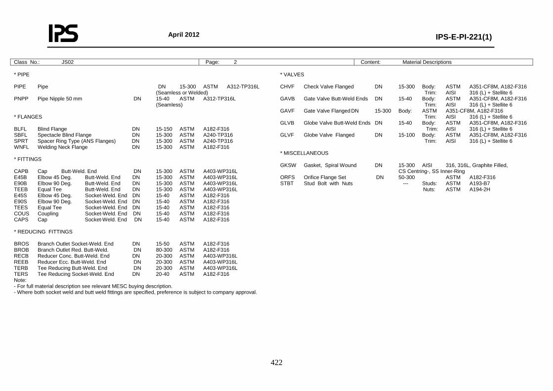
April 2012
IPS-E-PI-221(1)
422
Class No.: JS02 Page: 2 Content: Material Descriptions
* PIPE PIPE Pipe DN 15-300 ASTM A312-TP316L (Seamless or Welded) PNPP Pipe Nipple 50 mm DN 15-40 ASTM A312-TP316L (Seamless) * FLANGES BLFL Blind Flange DN 15-150 ASTM A182-F316 SBFL Spectacle Blind Flange DN 15-300 ASTM A240-TP316 SPRT Spacer Ring Type (ANS Flanges) DN 15-300 ASTM A240-TP316 WNFL Welding Neck Flange DN 15-300 ASTM A182-F316 * FITTINGS CAPB Cap Butt-Weld. End DN 15-300 ASTM A403-WP316L E45B Elbow 45 Deg. Butt-Weld. End DN 15-300 ASTM A403-WP316L E90B Elbow 90 Deg. Butt-Weld. End DN 15-300 ASTM A403-WP316L TEEB Equal Tee Butt-Weld. End DN 15-300 ASTM A403-WP316L E45S Elbow 45 Deg. Socket-Weld. End DN 15-40 ASTM A182-F316 E90S Elbow 90 Deg. Socket-Weld. End DN 15-40 ASTM A182-F316 TEES Equal Tee Socket-Weld. End DN 15-40 ASTM A182-F316 COUS Coupling Socket-Weld. End DN 15-40 ASTM A182-F316 CAPS Cap Socket-Weld. End DN 15-40 ASTM A182-F316 * REDUCING FITTINGS BROS Branch Outlet Socket-Weld. End DN 15-50 ASTM A182-F316 BROB Branch Outlet Red. Butt-Weld. DN 80-300 ASTM A182-F316 RECB Reducer Conc. Butt-Weld. End DN 20-300 ASTM A403-WP316L REEB Reducer Ecc. Butt-Weld. End DN 20-300 ASTM A403-WP316L TERB Tee Reducing Butt-Weld. End DN 20-300 ASTM A403-WP316L TERS Tee Reducing Socket-Weld. End DN 20-40 ASTM A182-F316 Note: - For full material description see relevant MESC buying description. - Where both socket weld and butt weld fittings are specified, preference is subject to company approval.
* VALVES CHVF Check Valve Flanged DN 15-300 Body: ASTM A351-CF8M, A182-F316 Trim: AISI 316 (L) + Stellite 6 GAVB Gate Valve Butt-Weld Ends DN 15-40 Body: ASTM A351-CF8M, A182-F316 Trim: AISI 316 (L) + Stellite 6 GAVF Gate Valve Flanged DN 15-300 Body: ASTM A351-CF8M, A182-F316 Trim: AISI 316 (L) + Stellite 6 GLVB Globe Valve Butt-Weld Ends DN 15-40 Body: ASTM A351-CF8M, A182-F316 Trim: AISI 316 (L) + Stellite 6 GLVF Globe Valve Flanged DN 15-100 Body: ASTM A351-CF8M, A182-F316 Trim: AISI 316 (L) + Stellite 6 * MISCELLANEOUS GKSW Gasket, Spiral Wound DN 15-300 AISI 316, 316L, Graphite Filled, CS Centring-, SS Inner-Ring ORFS Orifice Flange Set DN 50-300 ASTM A182-F316 STBT Stud Bolt with Nuts --- Studs: ASTM A193-B7 Nuts: ASTM A194-2H

April 2012
IPS-E-PI-221(1)
423
Class No.: JS02 Page: 3 Content: Piping Components
NOMINAL PIPE SIZE ITEM DESCRIPTION 15 20 25 40 50 80 100 150 200 250 300 * PIPE Pipe 74.36.40 * * * * * * * * * * * Pipe Nipple 50 mm * * * * * FLANGES Blind Flange 76.65.11 * * * * * * * * Spectacle Blind Flange 76.88.07 * * * * * * * * * * * Spacer Ring Type (ANS Flanges) * * * * * * * * * * * Welding Neck Flange 76.65.80 * * * * * * * * * * * * FITTINGS Cap Butt-Weld. End 76.33.18 * * * * * * * * * * * Elbow 45 Deg. Butt-Weld. End 76.33.38 * * * * * * * * * * * Elbow 90 Deg. Butt-Weld. End 76.33.40 * * * * * * * * * * * Equal Tee Butt-Weld. End 76.33.84 * * * * * * * * * * * Elbow 45 Deg. Socket-Weld. End 76.37.38 * * * * Elbow 90 Deg. Socket-Weld. End 76.37.39 * * * * Equal Tee Socket-Weld. End 76.37.80 * * * * Coupling Socket-Weld. End 76.37.28 * * * * Cap Socket-Weld. End 76.37.18 * * * * * VALVES Check Valve Flanged 75.40.11 * * * * * * * * * * * Gate Valve Butt-Weld Ends 75.58.31 * * * * Gate Valve Flanged 75.40.31 * * * * * * * * * * * Globe Valve Butt-Weld Ends 75.58.41 * * * * Globe Valve Flanged 75.40.41 * * * * * * * * MISCELLANEOUS Gasket, Spiral Wound 85.41.37 * * * * * * * * * * * Orifice Flange Set 60.88.52 * * * * * * *

April 2012
IPS-E-PI-221(1)
424
Class No.: JS02 Page: 4 Content: Reducing Piping Components
BROB RECB REEB TERB TERS Run Br. 76.79.71 76.33.70 76.33.73 76.33.85 76.37.85
COMP. NAME DESCRIPTION
20 × 15 * * * * 25 × 15 * * * * 25 × 20 * * * * 40 × 15 * * * * 40 × 20 * * * * 40 × 25 * * * * 50 × 20 * * * 50 × 25 * * * 50 × 40 * * * 80 × 40 * * * 80 × 50 * * * * 100 × 40 * * * 100 × 50 * * * * 100 × 80 * * * * 150 × 50 * 150 × 80 * * * * 150 × 100 * * * * 200 × 50 * 200 × 80 * 200 × 100 * * * * 200 × 150 * * * * 250 × 50 * 250 × 80 * 250 × 100 * * * * 250 × 150 * * * * 250 × 200 * * * * 300 × 50 * 300 × 80 * 300 × 100 * 300 × 150 * * * * 300 × 200 * * * * 300 × 250 * * * *
BROS Branch Fitting Socket-Weld. Outlet BROB Branch Outlet Red. Butt-Weld RECB Reducer Conc. Butt-Weld. End REEB Reducer Ecc. Butt-Weld. End TERB Tee Reducing Butt-Weld. End TERS Tee Reducing Socket-Weld. End
RUN Br. BROS 76.83.38
40-150 15 * 200-300 * 50-80 20 * 100-300 * 50 25 * 80-100 * 150-300 * 80-100 40 * 150-300 *
Class No.: JS02 Page: 5 Content: Bolting and Assemblies
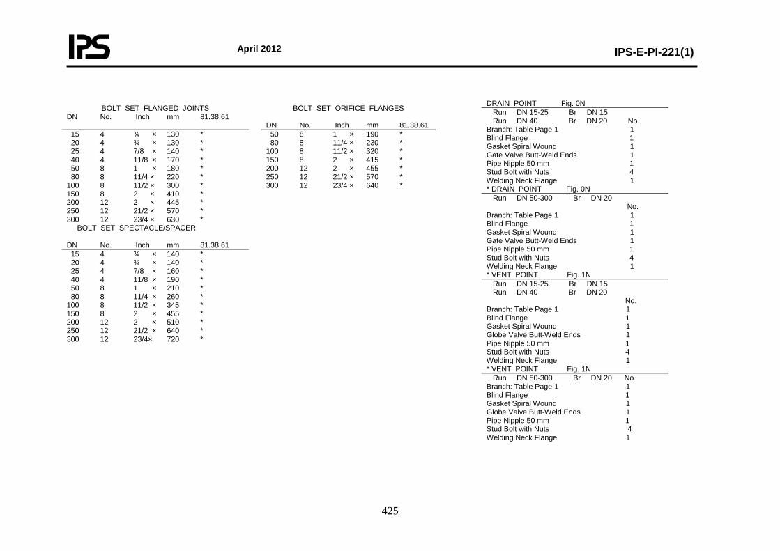
April 2012
IPS-E-PI-221(1)
425
BOLT SET FLANGED JOINTS DN No. Inch mm 81.38.61
BOLT SET ORIFICE FLANGES DN No. Inch mm 81.38.61
15 4 ¾ × 130 * 20 4 ¾ × 130 * 25 4 7/8 × 140 * 40 4 11/8 × 170 * 50 8 1 × 180 * 80 8 11/4 × 220 * 100 8 11/2 × 300 * 150 8 2 × 410 * 200 12 2 × 445 * 250 12 21/2 × 570 * 300 12 23/4 × 630 *
50 8 1 × 190 * 80 8 11/4 × 230 * 100 8 11/2 × 320 * 150 8 2 × 415 * 200 12 2 × 455 * 250 12 21/2 × 570 * 300 12 23/4 × 640 *
BOLT SET SPECTACLE/SPACER DN No. Inch mm 81.38.61
15 4 ¾ × 140 * 20 4 ¾ × 140 * 25 4 7/8 × 160 * 40 4 11/8 × 190 * 50 8 1 × 210 * 80 8 11/4 × 260 * 100 8 11/2 × 345 * 150 8 2 × 455 * 200 12 2 × 510 * 250 12 21/2 × 640 * 300 12 23/4× 720 *
DRAIN POINT Fig. 0N Run DN 15-25 Br DN 15 Run DN 40 Br DN 20 No. Branch: Table Page 1 1 Blind Flange 1 Gasket Spiral Wound 1 Gate Valve Butt-Weld Ends 1 Pipe Nipple 50 mm 1 Stud Bolt with Nuts 4 Welding Neck Flange 1 * DRAIN POINT Fig. 0N Run DN 50-300 Br DN 20 No. Branch: Table Page 1 1 Blind Flange 1 Gasket Spiral Wound 1 Gate Valve Butt-Weld Ends 1 Pipe Nipple 50 mm 1 Stud Bolt with Nuts 4 Welding Neck Flange 1 * VENT POINT Fig. 1N Run DN 15-25 Br DN 15 Run DN 40 Br DN 20 No. Branch: Table Page 1 1 Blind Flange 1 Gasket Spiral Wound 1 Globe Valve Butt-Weld Ends 1 Pipe Nipple 50 mm 1 Stud Bolt with Nuts 4 Welding Neck Flange 1 * VENT POINT Fig. 1N Run DN 50-300 Br DN 20 No. Branch: Table Page 1 1 Blind Flange 1 Gasket Spiral Wound 1 Globe Valve Butt-Weld Ends 1 Pipe Nipple 50 mm 1 Stud Bolt with Nuts 4 Welding Neck Flange 1
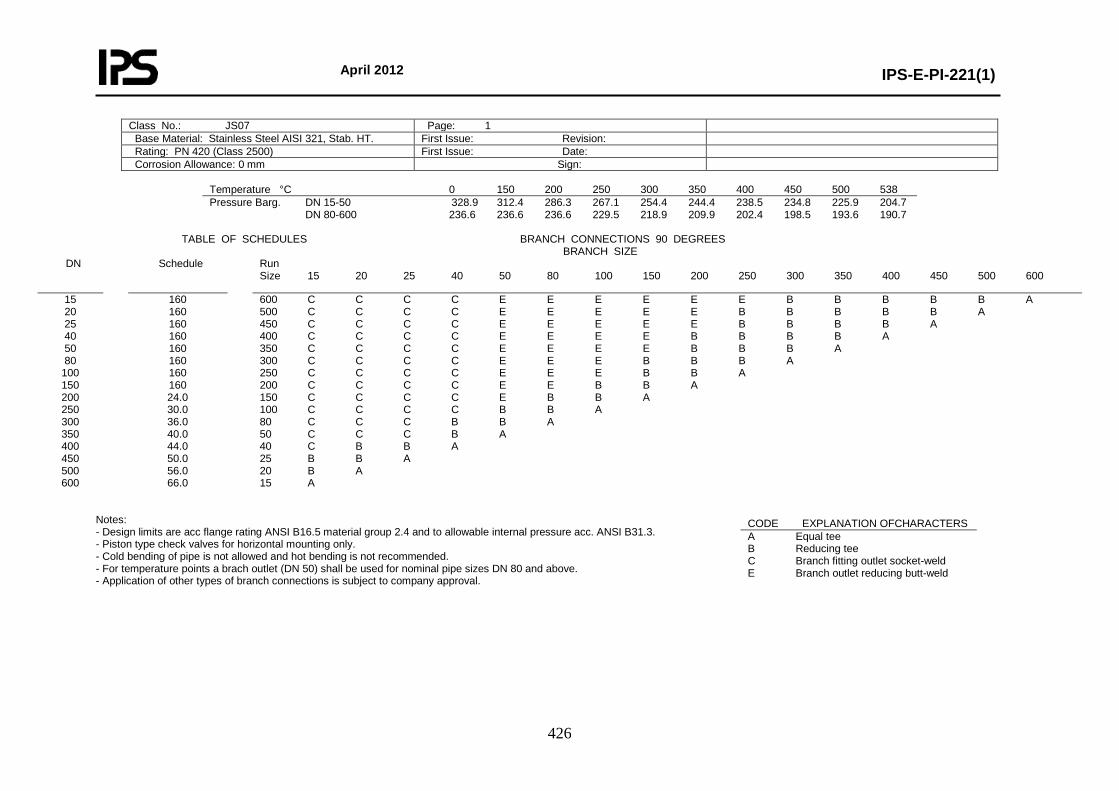
April 2012
IPS-E-PI-221(1)
426
Class No.: JS07 Page: 1 Base Material: Stainless Steel AISI 321, Stab. HT. First Issue: Revision: Rating: PN 420 (Class 2500) First Issue: Date: Corrosion Allowance: 0 mm Sign:
Temperature °C 0 150 200 250 300 350 400 450 500 538 Pressure Barg. DN 15-50 328.9 312.4 286.3 267.1 254.4 244.4 238.5 234.8 225.9 204.7 DN 80-600 236.6 236.6 236.6 229.5 218.9 209.9 202.4 198.5 193.6 190.7
TABLE OF SCHEDULES BRANCH CONNECTIONS 90 DEGREES BRANCH SIZE
DN Schedule Run Size 15 20 25 40 50 80 100 150 200 250 300 350 400 450 500 600
15 20 25 40 50 80
100 150 200 250 300 350 400 450 500 600
160 160 160 160 160 160 160 160 24.0 30.0 36.0 40.0 44.0 50.0 56.0 66.0
600 C C C C E E E E E E B B B B B A 500 C C C C E E E E E B B B B B A 450 C C C C E E E E E B B B B A 400 C C C C E E E E B B B B A 350 C C C C E E E E B B B A 300 C C C C E E E B B B A 250 C C C C E E E B B A 200 C C C C E E B B A 150 C C C C E B B A 100 C C C C B B A 80 C C C B B A 50 C C C B A 40 C B B A 25 B B A 20 B A 15 A
Notes: - Design limits are acc flange rating ANSI B16.5 material group 2.4 and to allowable internal pressure acc. ANSI B31.3. - Piston type check valves for horizontal mounting only. - Cold bending of pipe is not allowed and hot bending is not recommended. - For temperature points a brach outlet (DN 50) shall be used for nominal pipe sizes DN 80 and above. - Application of other types of branch connections is subject to company approval.
CODE EXPLANATION OFCHARACTERS A Equal tee B Reducing tee C Branch fitting outlet socket-weld E Branch outlet reducing butt-weld
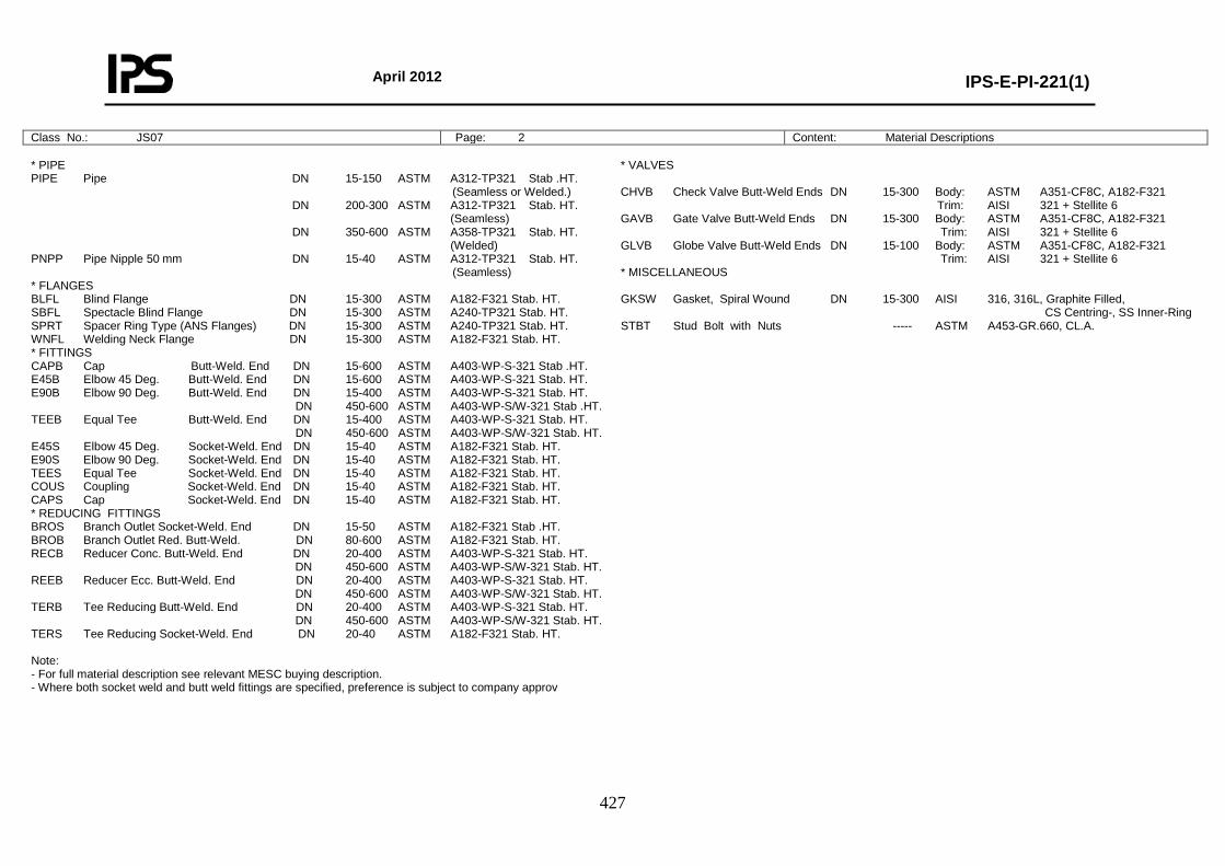
April 2012
IPS-E-PI-221(1)
427
Class No.: JS07 Page: 2 Content: Material Descriptions
* PIPE PIPE Pipe DN 15-150 ASTM A312-TP321 Stab .HT. (Seamless or Welded.) DN 200-300 ASTM A312-TP321 Stab. HT. (Seamless) DN 350-600 ASTM A358-TP321 Stab. HT. (Welded) PNPP Pipe Nipple 50 mm DN 15-40 ASTM A312-TP321 Stab. HT. (Seamless) * FLANGES BLFL Blind Flange DN 15-300 ASTM A182-F321 Stab. HT. SBFL Spectacle Blind Flange DN 15-300 ASTM A240-TP321 Stab. HT. SPRT Spacer Ring Type (ANS Flanges) DN 15-300 ASTM A240-TP321 Stab. HT. WNFL Welding Neck Flange DN 15-300 ASTM A182-F321 Stab. HT. * FITTINGS CAPB Cap Butt-Weld. End DN 15-600 ASTM A403-WP-S-321 Stab .HT. E45B Elbow 45 Deg. Butt-Weld. End DN 15-600 ASTM A403-WP-S-321 Stab. HT. E90B Elbow 90 Deg. Butt-Weld. End DN 15-400 ASTM A403-WP-S-321 Stab. HT. DN 450-600 ASTM A403-WP-S/W-321 Stab .HT. TEEB Equal Tee Butt-Weld. End DN 15-400 ASTM A403-WP-S-321 Stab. HT. DN 450-600 ASTM A403-WP-S/W-321 Stab. HT. E45S Elbow 45 Deg. Socket-Weld. End DN 15-40 ASTM A182-F321 Stab. HT. E90S Elbow 90 Deg. Socket-Weld. End DN 15-40 ASTM A182-F321 Stab. HT. TEES Equal Tee Socket-Weld. End DN 15-40 ASTM A182-F321 Stab. HT. COUS Coupling Socket-Weld. End DN 15-40 ASTM A182-F321 Stab. HT. CAPS Cap Socket-Weld. End DN 15-40 ASTM A182-F321 Stab. HT. * REDUCING FITTINGS BROS Branch Outlet Socket-Weld. End DN 15-50 ASTM A182-F321 Stab .HT. BROB Branch Outlet Red. Butt-Weld. DN 80-600 ASTM A182-F321 Stab. HT. RECB Reducer Conc. Butt-Weld. End DN 20-400 ASTM A403-WP-S-321 Stab. HT. DN 450-600 ASTM A403-WP-S/W-321 Stab. HT. REEB Reducer Ecc. Butt-Weld. End DN 20-400 ASTM A403-WP-S-321 Stab. HT. DN 450-600 ASTM A403-WP-S/W-321 Stab. HT. TERB Tee Reducing Butt-Weld. End DN 20-400 ASTM A403-WP-S-321 Stab. HT. DN 450-600 ASTM A403-WP-S/W-321 Stab. HT. TERS Tee Reducing Socket-Weld. End DN 20-40 ASTM A182-F321 Stab. HT. Note: - For full material description see relevant MESC buying description. - Where both socket weld and butt weld fittings are specified, preference is subject to company approv
* VALVES CHVB Check Valve Butt-Weld Ends DN 15-300 Body: ASTM A351-CF8C, A182-F321 Trim: AISI 321 + Stellite 6 GAVB Gate Valve Butt-Weld Ends DN 15-300 Body: ASTM A351-CF8C, A182-F321 Trim: AISI 321 + Stellite 6 GLVB Globe Valve Butt-Weld Ends DN 15-100 Body: ASTM A351-CF8C, A182-F321 Trim: AISI 321 + Stellite 6 * MISCELLANEOUS GKSW Gasket, Spiral Wound DN 15-300 AISI 316, 316L, Graphite Filled, CS Centring-, SS Inner-Ring STBT Stud Bolt with Nuts ----- ASTM A453-GR.660, CL.A.
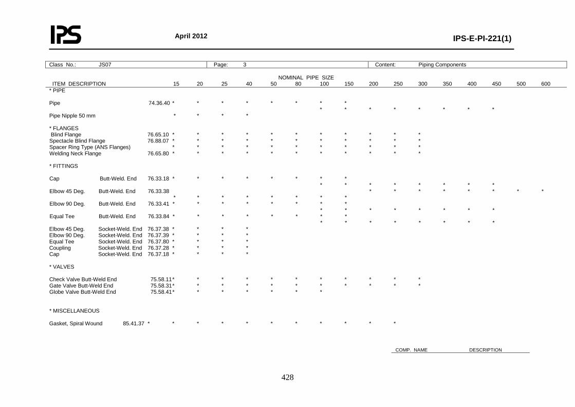
April 2012
IPS-E-PI-221(1)
428
Class No.: JS07 Page: 3 Content: Piping Components
NOMINAL PIPE SIZE ITEM DESCRIPTION 15 20 25 40 50 80 100 150 200 250 300 350 400 450 500 600 * PIPE Pipe 74.36.40 * * * * * * * * * * * * * * * * Pipe Nipple 50 mm * * * * * FLANGES Blind Flange 76.65.10 * * * * * * * * * * * Spectacle Blind Flange 76.88.07 * * * * * * * * * * * Spacer Ring Type (ANS Flanges) * * * * * * * * * * * Welding Neck Flange 76.65.80 * * * * * * * * * * * * FITTINGS Cap Butt-Weld. End 76.33.18 * * * * * * * * * * * * * * * * Elbow 45 Deg. Butt-Weld. End 76.33.38 * * * * * * * * * * * * * * * * Elbow 90 Deg. Butt-Weld. End 76.33.41 * * * * * * * * * * * * * * * * Equal Tee Butt-Weld. End 76.33.84 * * * * * * * * * * * * * * * * Elbow 45 Deg. Socket-Weld. End 76.37.38 * * * * Elbow 90 Deg. Socket-Weld. End 76.37.39 * * * * Equal Tee Socket-Weld. End 76.37.80 * * * * Coupling Socket-Weld. End 76.37.28 * * * * Cap Socket-Weld. End 76.37.18 * * * * * VALVES Check Valve Butt-Weld End 75.58.11 * * * * * * * * * * * Gate Valve Butt-Weld End 75.58.31 * * * * * * * * * * * Globe Valve Butt-Weld End 75.58.41 * * * * * * * * MISCELLANEOUS Gasket, Spiral Wound 85.41.37 * * * * * * * * * * *
COMP. NAME DESCRIPTION
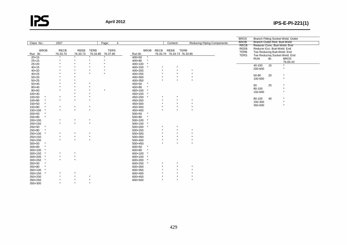
April 2012
IPS-E-PI-221(1)
429
BROS Branch Fitting Socket-Weld. Outlet BROB Branch Outlet Red. Butt-Weld RECB Reducer Conc. Butt-Weld. End REEB Reducer Ecc. Butt-Weld. End TERB Tee Reducing Butt-Weld. End TERS Tee Reducing Socket-Weld. End RUN Br. BROS 76.83.43 40-150 15 * 200-600 * 50-80 20 * 100-600 * 50 25 * 80-100 * 150-600 * 80-100 40 * 150-300 * 350-600 *
Class No.: JS07 Page: 4 Content: Reducing Piping Components
BROB RECB REEB TERB TERS Run Br. 76.33.70 76.33.73 76.33.85 76.37.85
BROB RECB REEB TERB Run Br. 76.33.70 76.33.73 76.33.85
20×15 * * * * 25×15 * * * * 25×20 * * * * 40×15 * * * * 40×20 * * * * 40×25 * * * * 50×20 * * 50×25 * * 50×40 * * * 80×40 * * * 80×50 * * * * 100×40 * * 100×50 * * * * 100×80 * * * * 150×50 * 150×80 * * * * 150×100 * * * * 200×50 * 200×80 * 200×100 * * * 200×150 * * * 250×50 * 250×80 * 250×100 * * * * 250×150 * * * 250×200 * * * 300×50 * 300×80 * 300×100 * 300×150 * * * 300×200 * * * 300×250 * * * 350×50 * 350×80 * 350×100 * 350×150 * * * 350×200 * * * 350×250 * * * 350×300 * * *
400×50 * 400×80 * 400×100 * 400×150 * * * 400×200 * * * 400×250 * * * 400×300 * * * 400×350 * * * 450×50 * 450×80 * 450×100 * 450×150 * 450×200 * * * 450×250 * * * 450×300 * * * 450×350 * * * 450×400 * * * 500×50 * 500×80 * 500×100 * 500×150 * 500×200 * * * 500×250 * * * 500×300 * * * 500×350 * * * 500×400 * * * 500×450 * * * 600×50 * 600×80 * 600×100 * 600×150 * 600×200 * 600×250 * * * 600×300 * * * 600×350 * * * 600×400 * * * 600×450 * * * 600×500 * * *
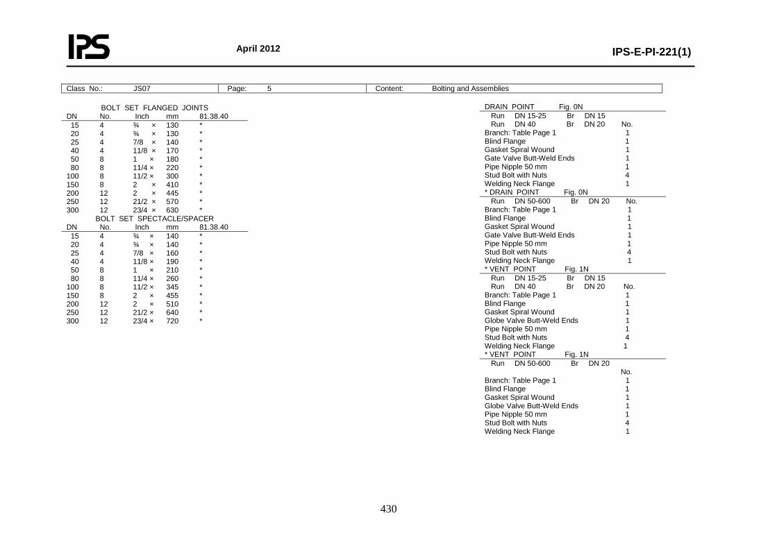
April 2012
IPS-E-PI-221(1)
430
Class No.: JS07 Page: 5 Content: Bolting and Assemblies
BOLT SET FLANGED JOINTS DN No. Inch mm 81.38.40
15 4 ¾ × 130 * 20 4 ¾ × 130 * 25 4 7/8 × 140 * 40 4 11/8 × 170 * 50 8 1 × 180 * 80 8 11/4 × 220 * 100 8 11/2 × 300 * 150 8 2 × 410 * 200 12 2 × 445 * 250 12 21/2 × 570 * 300 12 23/4 × 630 *
BOLT SET SPECTACLE/SPACER DN No. Inch mm 81.38.40
15 4 ¾ × 140 * 20 4 ¾ × 140 * 25 4 7/8 × 160 * 40 4 11/8 × 190 * 50 8 1 × 210 * 80 8 11/4 × 260 * 100 8 11/2 × 345 * 150 8 2 × 455 * 200 12 2 × 510 * 250 12 21/2 × 640 * 300 12 23/4 × 720 *
DRAIN POINT Fig. 0N Run DN 15-25 Br DN 15 Run DN 40 Br DN 20 No. Branch: Table Page 1 1 Blind Flange 1 Gasket Spiral Wound 1 Gate Valve Butt-Weld Ends 1 Pipe Nipple 50 mm 1 Stud Bolt with Nuts 4 Welding Neck Flange 1 * DRAIN POINT Fig. 0N Run DN 50-600 Br DN 20 No. Branch: Table Page 1 1 Blind Flange 1 Gasket Spiral Wound 1 Gate Valve Butt-Weld Ends 1 Pipe Nipple 50 mm 1 Stud Bolt with Nuts 4 Welding Neck Flange 1 * VENT POINT Fig. 1N Run DN 15-25 Br DN 15 Run DN 40 Br DN 20 No. Branch: Table Page 1 1 Blind Flange 1 Gasket Spiral Wound 1 Globe Valve Butt-Weld Ends 1 Pipe Nipple 50 mm 1 Stud Bolt with Nuts 4 Welding Neck Flange 1 * VENT POINT Fig. 1N Run DN 50-600 Br DN 20 No. Branch: Table Page 1 1 Blind Flange 1 Gasket Spiral Wound 1 Globe Valve Butt-Weld Ends 1 Pipe Nipple 50 mm 1 Stud Bolt with Nuts 4 Welding Neck Flange 1