english · • using unapproved auxiliary equipment • operating equipment in excess of maximum...
TRANSCRIPT

This document is subject to change without notice. Check http://www.vernetechnology.it for the latest version.
ENGLISH
415
/N 10045-_ _ Customer Product Manual Part
Low pressure dense phase transport system

Table of Contets
SafetyQualified PersonnelIntended Use Regulations and Approvals Personal Safety Fire Safety Grounding Action in the Event of a Malfunction Disposal
DisposalPump group partsSpacerManifold: valve diagramManifold group NEA 415 technical data
Cyclic pressures
MaintenanceDiagnostics
RepairFluidization tube replacementDisassembly of the pumpPump assemblyReplacement of the pinch valve
Spare parts
Contact usVERNE TECHNOLOGY welcomes requests for information, comments, and inquiries about its products. General information about VERNE TECHNOLOGY can be found on the Internet using the following address: http://www.vernetechnology.it.
NoteThis is a VERNE TECHNOLOGY publication which is protected by copyright. Original copyright date 2017. No part of this document may be photocopied, reproduced, or translated to another language without the prior written consent of VERNE TECHNOLOGY. The information contained in this publication is subject to change without notice.
11112233
4567
8
18
21222326
28
Technical specificationsPower supplies and transportDimensions
1011
PN 10046-_ _Pump components NEA 415Principle of operationTechnical dataDust pipe installation
13141617
19

Low pressure dense phase transport system NEA 415
©
CONTACTSADMINISTRATIVE HEADQUARTERS:
Verne Technology S.r.l.Via Montenapoleone, 820121 - MILANO (MI) - ITALY-Tel. +39 (0)2-783275 | Fax +39 (0)2-784087
e-mail: [email protected]
LOGISTICS: (shipping and delivery)
Via Elettrochimica1, 23900LECCO (LC) - ITALY -Tel. +39 (0)341-423183
e-mail: [email protected]

Low pressure dense phase transport system NEA 4151
©
Safety
Read and follow these safety instructions. Task-and equipment-specific warnings, cautions, and instructions are included in equipment documentation where appropriate.
Make sure all equipment documentation, including these instructions, is accessible to all persons operating or servicing equipment.
Qualified Personnel
Equipment owners are responsible for making sure that Vere Technology equipment is installed, operated, and serviced by qualified personnel. Qualified personnel are those employees or contractors who are trained to safely perform their assigned tasks. They are familiar with all relevant safety rules and regulations and are physically capable of performing their assigned tasks.
Intended Use
Use of NEA 415 equipment in ways other than those described in the documentation supplied with the equipment may result in injury to persons or damage to property. Some examples of unintended use of equipment include • using incompatible materials • making unauthorized modifications • removing or bypassing safety guards or interlocks • using incompatible or damaged parts • using unapproved auxiliary equipment • operating equipment in excess of maximum ratings
Regulations and Approvals Make sure all equipment is rated and approved for the environment in which it is used. Any approvals obtai-ned for Verne Technology equipment will be voided if instructions for installation, operation, and service are not followed.
All phases of equipment installation must comply with all federal, state, and local codes.
Personal Safety
To prevent injury follow these instructions.
• Do not operate or service equipment unless you are qualified.
• Do not operate equipment unless safety guards, doors, or covers are intact and automatic interlocks are operating properly. Do not bypass or disarm any safety devices.
• Keep clear of moving equipment. Before adjusting or servicing any moving equipment, shut off the power supply and wait until the equipment comes to a complete stop. Lock out power and secure the equipment to prevent unexpected movement.
• Relieve (bleed off) hydraulic and pneumatic pressure before adjusting or servicing pressurized systems or components. Disconnect, lock out, and tag switches before servicing electrical equipment.
• Obtain and read Material Safety Data Sheets (MSDS) for all materials used. Follow the manufacturer’s instructions for safe handling and use of materials, and use recommended personal protection device Grounding inside and around the booth openings must comply with NFPA requirements for Class 2, Division 1 or 2 Hazardous Locations. Refer to NFPA 33, NFPA 70 (NEC articles 500, 502, and 516), and NFPA 77, latest conditions.
• To prevent injury, be aware of less-obvious dangers in the workplace that often cannot be completely elimi- nated, such as hot surfaces, sharp edges, energized electrical circuits, and moving parts that cannot be enclosed or otherwise guarded for practical reasons.

Low pressure dense phase transport system NEA 4152
©
Fire Safety
To avoid a fire or explosion, follow these instructions.
• Do not smoke, weld, grind, or use open flames where flammable materials are being used or stored. • Provide adequate ventilation to prevent dangerous concentrations of volatile materials or vapors. Refer to local codes or your material MSDS for guidance.
• Do not disconnect live electrical circuits while working with flammable materials. Shut off power at a disconnect switch first to prevent sparking.
• Know where emergency stop buttons, shutoff valves, and fire extinguishers are located. If a fire starts in a spray booth, immediately shut off the spray system and exhaust fans.
• Clean, maintain, test, and repair equipment according to the instructions in your equipment documenta- tion.
• Use only replacement parts that are designed for use with original equipment. Contact your Vere Technology representative for parts information and advice.
Grounding
WARNING: Operating faulty electrostatic equipment is hazardous and can cause electro-cution, fire, or explosion. Make resistance checks part of your periodic maintenance program. If you receive even a slight electrical shock or notice static sparking or arcing, shut down all electrical or electrostatic equipment immediately. Do not restart the equipment until the problem has been identified and corrected
• All electrically conductive objects in the spray areas shall be electrically connected to ground with a resistance of not more than 1 megohm as measured with an instrument that applies at least 500 volts to the circuit being evaluated.
• Equipment to be grounded includes, but is not limited to, the floor of the spray area, operator platforms, hoppers, photoeye supports, and blow-off nozzles. Personnel working in the spray area must be grounded.
• There is a possible ignition potential from the charged human body. Personnel standing on a painted surface, such as an operator platform, or wearing non-conductive shoes, are not grounded. Personnel must wear shoes with conductive soles or use a ground strap to maintain a connection to ground when working with or around electrostatic equipment. • Operators must maintain skin-to-handle contact between their hand and the gun handle to prevent shocks while operating manual electrostatic spray guns. If gloves must be worn, cut away the palm or fingers, wear electrically conductive gloves, or wear a grounding strap connected to the gun handle or other true earth ground. • Shut off electrostatic power supplies and ground gun electrodes before making adjustments or cleaning powder spray guns. • Connect all disconnected equipment, ground cables, and wires after servicing equipment.
Intervention in case of malfunctionIf a system or equipment in your system malfunctions, immediately turn off the system and perform the following steps:
•
• Identify the reason for the malfunction and correct the problem before restarting the equipment.
Disposal
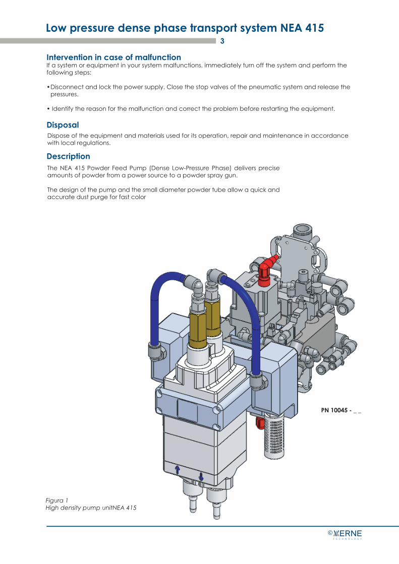
Description
Low pressure dense phase transport system NEA 4153
©
Figura 1High density pump unitNEA 415
PN 10045 - _ _
Disconnect and lock the power supply. Close the stop valves of the pneumatic system and release the pressures.
Dispose of the equipment and materials used for its operation, repair and maintenance in accordance with local regulations.
The NEA 415 Powder Feed Pump (Dense Low-Pressure Phase) delivers precise amounts of powder from a power source to a powder spray gun.
The design of the pump and the small diameter powder tube allow a quick and accurate dust purge for fast color
Low pressure dense phase transport system NEA 415 4
©
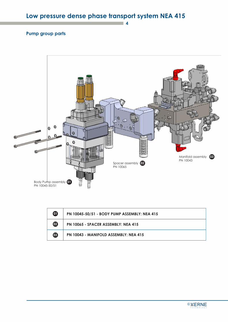
Pump group parts
01
02
03
Body Pump assemblyPN 10045-50/51
Spacer assemblyPN 10065
Manifold assemblyPN 10043
01
02
03
PN 10045-50/51 - BODY PUMP ASSEMBLY: NEA 415
PN 10065 - SPACER ASSEMBLY: NEA 415
PN 10043 - MANIFOLD ASSEMBLY: NEA 415
Low pressure dense phase transport system NEA 415 5
©
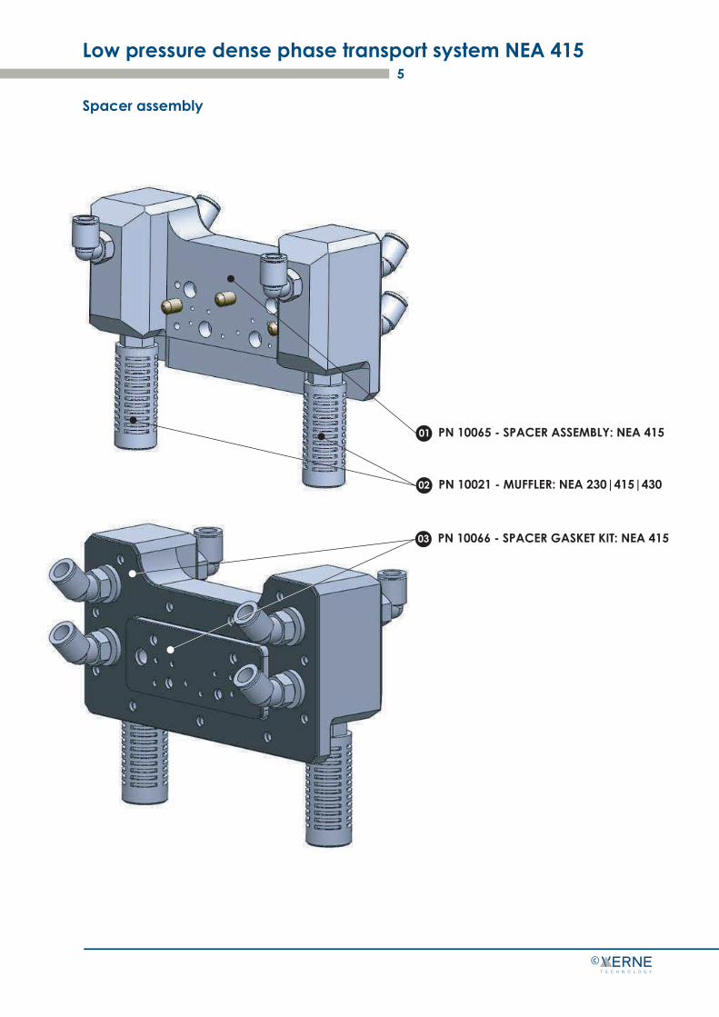
Spacer assembly
01 PN 10065 - SPACER ASSEMBLY: NEA 415
02 PN 10021 - MUFFLER: NEA 230|415|430
03 PN 10066 - SPACER GASKET KIT: NEA 415
Low pressure dense phase transport system NEA 415 6
©
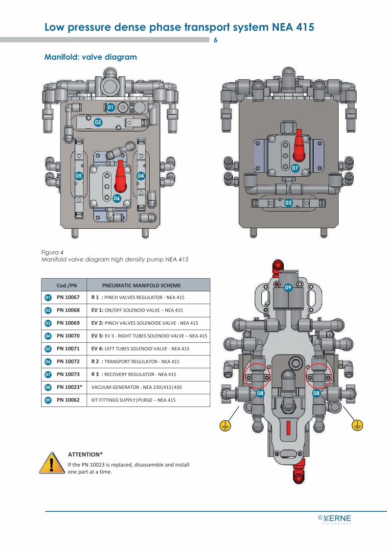
Manifold: valve diagram
01
01
02
05
06
0407
03
02
03
04
05
06
07
08
09
PN 10067 R 1 : PINCH VALVES REGULATOR - NEA 415
PN 10068 EV 1: ON/OFF SOLENOID VALVE – NEA 415
PN 10069 EV 2: PINCH VALVES SOLENOIDE VALVE - NEA 415
PN 10070 EV 3: EV 3 - RIGHT TUBES SOLENOID VALVE – NEA 415
PN 10071 EV 4: LEFT TUBES SOLENOID VALVE - NEA 415
PN 10072 R 2 : TRANSPORT REGULATOR - NEA 415
PN 10073 R 3 : RECOVERY REGULATOR - NEA 415
PN 10023* VACUUM GENERATOR - NEA 230|415|430
PN 10062 KIT FITTINGS SUPPLY|PURGE – NEA 415
PNEUMATIC MANIFOLD SCHEMECod./PN
0808
09
Figura 4Manifold valve diagram high density pump NEA 415
If the PN 10023 is replaced, disassemble and install one part at a time.
ATTENTION*

NEA 415 pump manifold groupSee fig. 4.
Low pressure dense phase transport system NEA 415 7
©
Air control components
1
2
3
4
5
6
7
8
9
EV3Apply positive and negative compressed air to the right fluidization tubes alternately.
EV4
Control valve of the pinch valveEV2
Apply compressed air between the pinch valves alternately.
Regulator and pressure gauge (RECOVERY)R3
Silencers Allows a silent output of the pump operating air.
Regulator and pressure gauge (PINCH VALVES)R1
Adjusts the pressure of the vacuum generators. Variable from PLC.
Vacuum generators Based on the venturi principle, it generates the negative air pressure necessary to attract dust into the fluidization tubes.
Cycle activation check valveEV1
It supplies all the pneumatic components on the MANIFOLD body.
Regulator and pressure gauge (TRANSPORT)R2
Adjusts the transport pressure of the product.Variable from PLC.
Adjusts the closing pressure of the pinch valves.Set at 2,5 bar.
Description Function
Control valve for fluidization tubes of DX
Control valve for fluidization tubes of SX Apply positive and negative compressed air to the leftfluidization tubes alternately.
Low pressure dense phase transport system NEA 415 8
©
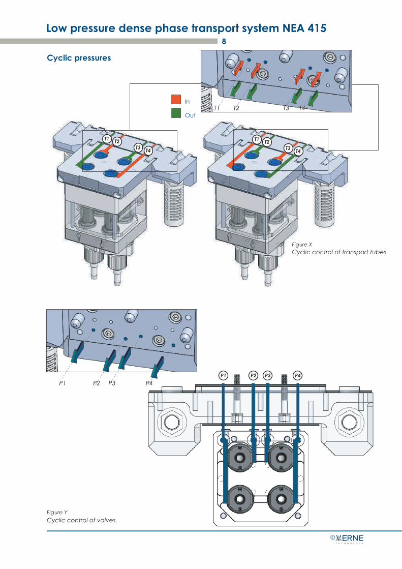
Cyclic pressures
Cyclic control of valvesFigure Y
In
Out
Figure XCyclic control of transport tubes
P1 P2 P3 P4 P1 P2 P3 P4
T1 T2T3 T4
T1 T2T3 T4
T1 T2 T3 T4

Low pressure dense phase transport system NEA 415 9
©
Technical specifications

Power supply and transport specifications
Low pressure dense phase transport system NEA 415 10
©
Exit (maxim) 400 gr/min
Weight / Dimensions P/N 10050-10051 Kg 14 - See fig. 5
Powder tube
Lenght
Dimension 10 mm ø D Est x 6 mm ø D Int
Manifold Group 415 NEA P / N 10043
Manifold air IN 6.0 bar (87 psi)
Voltage
Absorbed power 24W, 2.5A
Working air pressure
Pinch valves ( R1) 2,5 bar (35 psi)
Feeding pipe
Dimension ø10 mm 6.0 bar (87 psi)
125 VA with 24 Vdc
Pump NEA 415 P/N 10046 -_ _
Air intake cleaning (Purge 1 - Purge 2) Max 7.0 bar (100 psi)
Uscita: 10−35 m (20−98 foot)
Ingresso: 1−3 m (3,5−12 foot)
Cleaning pipe
Dimension ø16 mm Max 7.0 bar (100 psi)
Permissible air humidity 95% without condensation
Operating ambient temperature da +15 a +40 °C
pulsations transport max 600 pul/min
-- CLEANING VALVE NOT SUPPLIED --

Dimensions
Low pressure dense phase transport system NEA 415 11
©
350
mm
150
mm
200 mm
90 mm
290 mm
55 mm
240 mm 280 m
m

PN 10046-_ _ Body pump NEA 41512
©
Fig.1 PN 10046-_ _ Body pump NEA 415
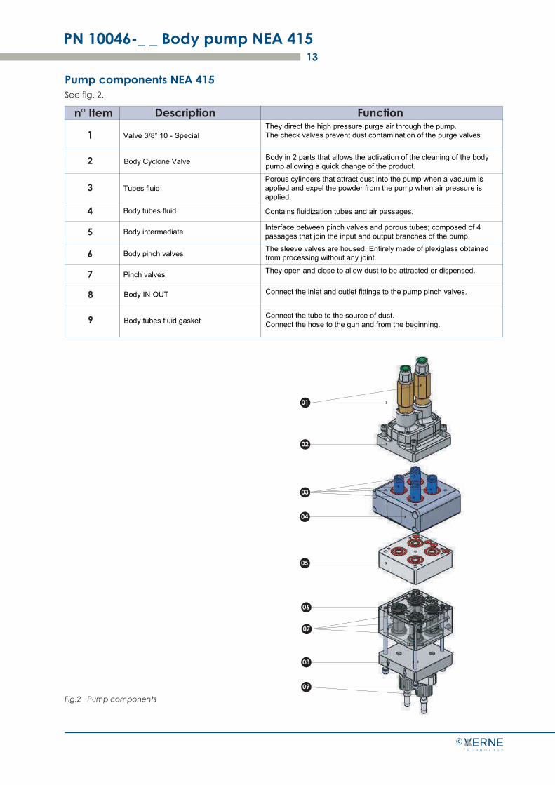
Pump components NEA 415See fig. 2.
PN 10046-_ _ Body pump NEA 41513
©
1
2
3
4
5
6
7
Tubes fluid
Body tubes fluid
Body intermediate
They direct the high pressure purge air through the pump. The check valves prevent dust contamination of the purge valves.
Porous cylinders that attract dust into the pump when a vacuum is applied and expel the powder from the pump when air pressure is applied.
Contains fluidization tubes and air passages.
Interface between pinch valves and porous tubes; composed of 4 passages that join the input and output branches of the pump.
01
02
03
04
05
07
06
08
09
Valve 3/8” 10 - Special
Body pinch valves The sleeve valves are housed. Entirely made of plexiglass obtained from processing without any joint.
Pinch valves They open and close to allow dust to be attracted or dispensed.
8 Body IN-OUT Connect the inlet and outlet fittings to the pump pinch valves.
9 Body tubes fluid gasketConnect the tube to the source of dust.Connect the hose to the gun and from the beginning.
Body Cyclone Valve Body in 2 parts that allows the activation of the cleaning of the body pump allowing a quick change of the product.
Fig.2 Pump components
Description Function

Principle of operation
Pumping
PN 10046-_ _ Body pump 41514
Fig.3Operating principle - pumping INOUT EMPTYFULL
©
The NEA 415 pump consists of two halves that function identically. The two halves alternately attract and dispense the powder from the pump; while one half attracts it, the other half dispenses it.
Air
Air
Air
Air
A
B
C
D
PN 10046-_ _ Body pump NEA 41515
©
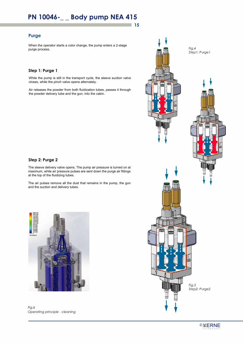
Purge
When the operator starts a color change, the pump enters a 2-stage purge process.
Step 1: Purge 1
Step 2: Purge 2
Fig.4 Step1: Purge1
Fig.6Operating principle - cleaning
Fig.5Step2: Purge2
While the pump is still in the transport cycle, the sleeve suction valve closes, while the pinch valve opens alternately.
Air releases the powder from both fluidization tubes, passes it through the powder delivery tube and the gun, into the cabin.
The sleeve delivery valve opens. The pump air pressure is turned on at maximum, while air pressure pulses are sent down the purge air fittings at the top of the fluidizing tubes.
The air pulses remove all the dust that remains in the pump, the gun and the suction and delivery tubes.

Technical data
PN 10046-_ _ Body pump NEA 41516
©
Fig.6 Dimensions of pump NEA 415
90
335
100

Installation of the powder tube
PN 10046-_ _ Body pump NEA 41517
©
Fig.7 Installation of the dust tube
Tube with 10 mm external ø in polyethylene or flexible
1. Unscrew the tightening nut anticlockwise.
2. Make sure the sealing oring is in the tube adapter housing (03).
3. Insert the nut of the sealing tube adapter and make it reach the end of the thread by turning it clockwise.
4. Push the adapter into the bottom of the IN-OUT input (fig.01).
5. Tighten the nut to the south IN-OUT input as far as it will go.
6. Insert the transport tube.
Fig. 7
01
02
03
04
05
Input IN-OUT sud
Tube adapter
Seal gasket
Clamping nut
Tube
NOTE: Cut the tube in polyethylene or flexible according to use with a special cutter. If the powder tube is cut unevenly there may be cross contamination of the powder. See fig. 7

MaintenancePerform maintenance operations to ensure that the pump always operates at maximum efficiency.
PN 10046-_ _ Body pump NEA 41518
©
DANGER: The following operations must be carried out by qualified personnel only. Follow the safety instructions in this manual and in all other manuals used.
NOTE: These operations must be performed with a higher or lower frequency depending on factors such as the experience of the operator and the type of powder used.
Frequency P/N Procedure
Daily
P/N: 10050 o 10051
P/N: 10061
P/N: 10060
P/N: 10058
P/N: 10056
P/N: 10055
P/N: 10054
P/N: 10052
Check to see if the pinch valve body shows signs of dust leakage. In the presen-ce of dust in the sleeve or crackle valve body in the pinch valves, replace the pinch valves and filter discs.
NOTE: To reduce downtime it is advisable to always reserve spare parts such as PN 10061, PN 10056 and PN 10054, to be installed while cleaning or checking the other set.
Remove the pump and check if the wear blocks show signs of wear or sinte-ring. If necessary, clean these components with an ultrasonic cleaning device.
Every four months or every time the pump is dismantled
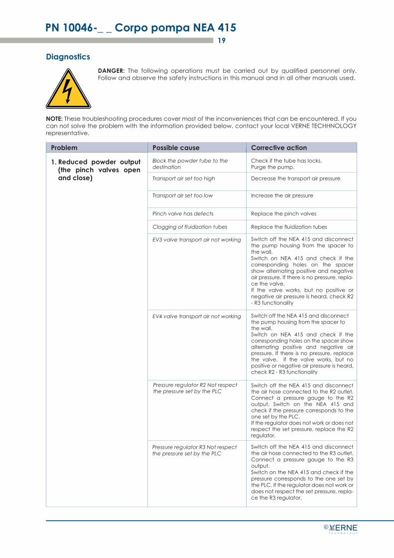
Diagnostics
PN 10046-_ _ Corpo pompa NEA 41519
©
Problem Possible cause Corrective action
1.
Transport air set too high
Transport air set too low
Check if the tube has locks. Purge the pump.
Decrease the transport air pressure
Increase the air pressure
Block the powder tube to the destination
Pinch valve has defects Replace the pinch valves
Clogging of fluidization tubes Replace the fluidization tubes
EV3 valve transport air not working
EV4 valve transport air not working
Pressure regulator R2 Not respect the pressure set by the PLC
Pressure regulator R3 Not respect the pressure set by the PLC
DANGER: The following operations must be carried out by qualified personnel only. Follow and observe the safety instructions in this manual and in all other manuals used.
NOTE: These troubleshooting procedures cover most of the inconveniences that can be encountered. If you can not solve the problem with the information provided below, contact your local VERNE TECHHNOLOGY representative.
Reduced powder output (the pinch valves open and close)
Switch off the NEA 415 and disconnect the pump housing from the spacer to the wall. Switch on NEA 415 and check if the corresponding holes on the spacer show alternating positive and negative air pressure. If there is no pressure, repla-ce the valve. If the valve works, but no positive or negative air pressure is heard, check R2 - R3 functionality
Switch off the NEA 415 and disconnect the pump housing from the spacer to the wall. Switch on NEA 415 and check if the corresponding holes on the spacer show alternating positive and negative air pressure. If there is no pressure, replace the valve. If the valve works, but no positive or negative air pressure is heard, check R2 - R3 functionality
Switch off the NEA 415 and disconnect the air hose connected to the R2 outlet. Connect a pressure gauge to the R2 output. Switch on the NEA 415 and check if the pressure corresponds to the one set by the PLC. If the regulator does not work or does not respect the set pressure, replace the R2 regulator.
Switch off the NEA 415 and disconnect the air hose connected to the R3 outlet. Connect a pressure gauge to the R3 output. Switch on the NEA 415 and check if the pressure corresponds to the one set by the PLC. If the regulator does not work or does not respect the set pressure, repla-ce the R3 regulator.
PN 10046-_ _ Body pump NEA 41520
©
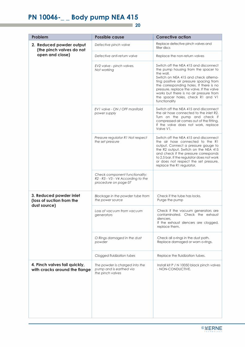
Problem Possible cause Corrective action
Defective pinch valve
Defective anti-return valve
Replace defective pinch valves and filter discs
Replace the non-return valves
Reduced powder output (the pinch valves do not open and close)
2.
EV2 valve - pinch valves. Not working
EV1 valve - ON / OFF manifold power supply
Pressure regulator R1 Not respect the set pressure
Check component functionality: R2 - R3 - V3 - V4 According to the procedure on page 07
3. Reduced powder inlet (loss of suction from the dust source)
Blockage in the powder tube from the power source
Check if the tube has locks. Purge the pump
Loss of vacuum from vacuum generators
O Rings damaged in the dust powder
Clogged fluidization tubes Replace the fluidization tubes.
4. Pinch valves fail quickly, with cracks around the flange
The powder is charged into the pump and is earthed via the pinch valves
Install kit P / N 10050 black pinch valves - NON-CONDUCTIVE.
Switch off the NEA 415 and disconnect the pump housing from the spacer to the wall. Switch on NEA 415 and check alterna-ting positive air pressure spacing from the corresponding holes. If there is no pressure, replace the valve. If the valve works but there is no air pressure from the spacer holes, check R1 and V1 functionality
Switch off the NEA 415 and disconnect the air hose connected to the inlet R2. Turn on the pump and check if compressed air comes out of the fitting. If the valve does not work, replace Valve V1.
Switch off the NEA 415 and disconnect the air hose connected to the R1 output. Connect a pressure gauge to the R2 output. Switch on the NEA 415 and check if the pressure corresponds to 2.5 bar. If the regulator does not work or does not respect the set pressure, replace the R1 regulator.
Check if the vacuum generators are contaminated. Check the exhaust silencers. If the exhaust silencers are clogged, replace them.
Check all o-rings in the dust path. Replace damaged or worn o-rings.
3 4
Switch off the pump and disconnect the tubes at the top and bottom
Repair
PN 10046-_ _ Body pump NEA 41521
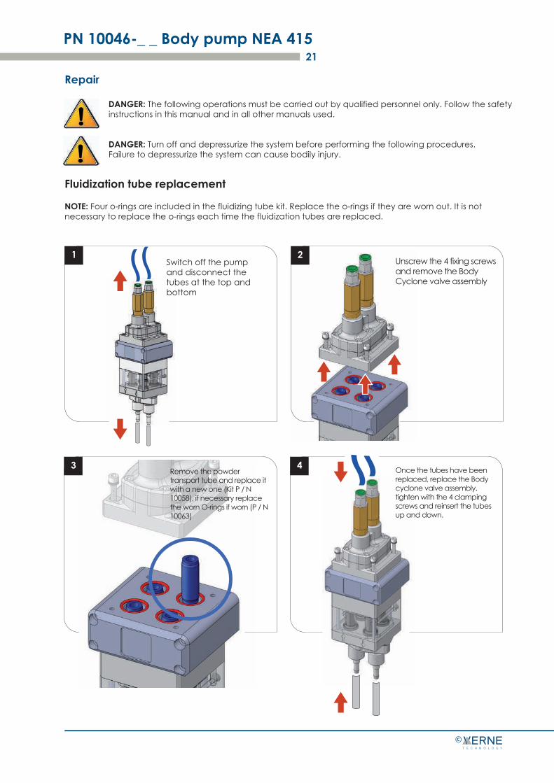
DANGER: The following operations must be carried out by qualified personnel only. Follow the safety instructions in this manual and in all other manuals used.
DANGER: Turn off and depressurize the system before performing the following procedures. Failure to depressurize the system can cause bodily injury.
©
Fluidization tube replacement
NOTE: Four o-rings are included in the fluidizing tube kit. Replace the o-rings if they are worn out. It is not necessary to replace the o-rings each time the fluidization tubes are replaced.
1 2Unscrew the 4 fixing screws and remove the Body Cyclone valve assembly
Remove the powder transport tube and replace it with a new one (Kit P / N 10058), if necessary replace the worn O-rings if worn (P / N 10063)
Once the tubes have been replaced, replace the Body cyclone valve assembly, tighten with the 4 clamping screws and reinsert the tubes up and down.
Disassembling pump
PN 10046-_ _ Body pump NEA 41522
-
©
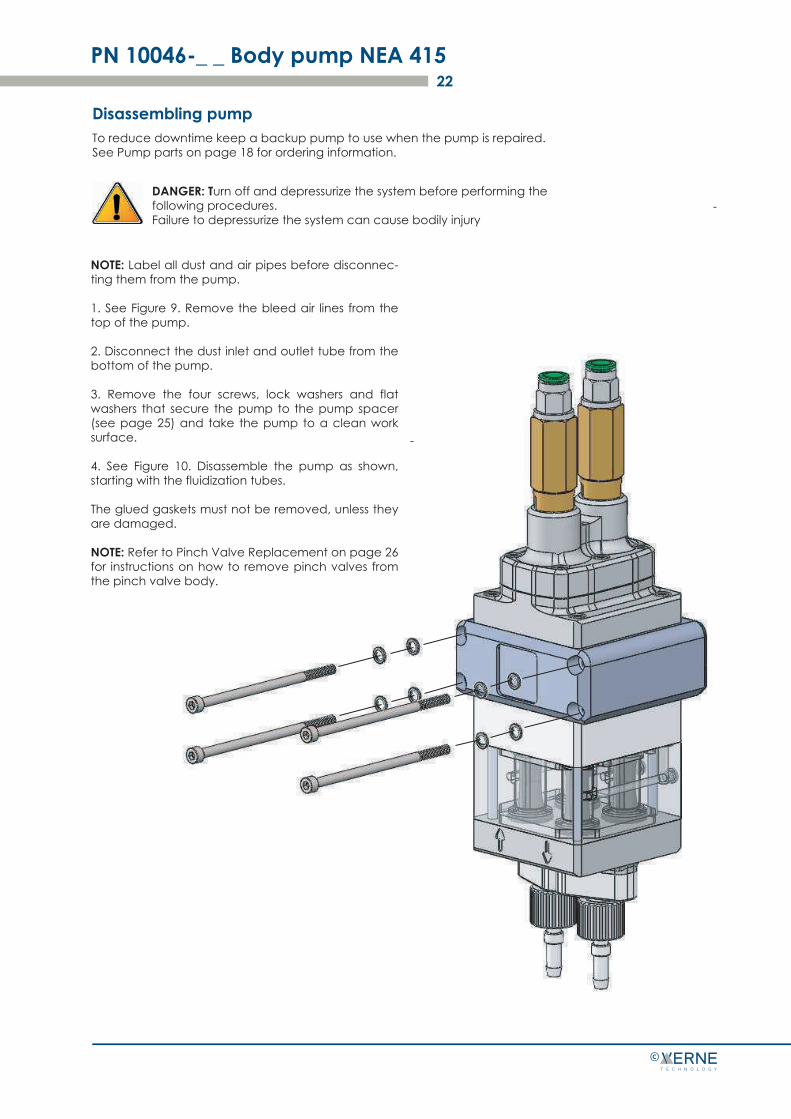
To reduce downtime keep a backup pump to use when the pump is repaired. See Pump parts on page 18 for ordering information.
DANGER: Turn off and depressurize the system before performing the following procedures. Failure to depressurize the system can cause bodily injury
-
NOTE: Label all dust and air pipes before disconnec-ting them from the pump.
1. See Figure 9. Remove the bleed air lines from the top of the pump.
2. Disconnect the dust inlet and outlet tube from the bottom of the pump.
3. Remove the four screws, lock washers and flat washers that secure the pump to the pump spacer (see page 25) and take the pump to a clean work surface.
4. See Figure 10. Disassemble the pump as shown, starting with the fluidization tubes.
The glued gaskets must not be removed, unless they are damaged.
NOTE: Refer to Pinch Valve Replacement on page 26 for instructions on how to remove pinch valves from the pinch valve body.
PN 10046-_ _ Body pump NEA 415
©
23
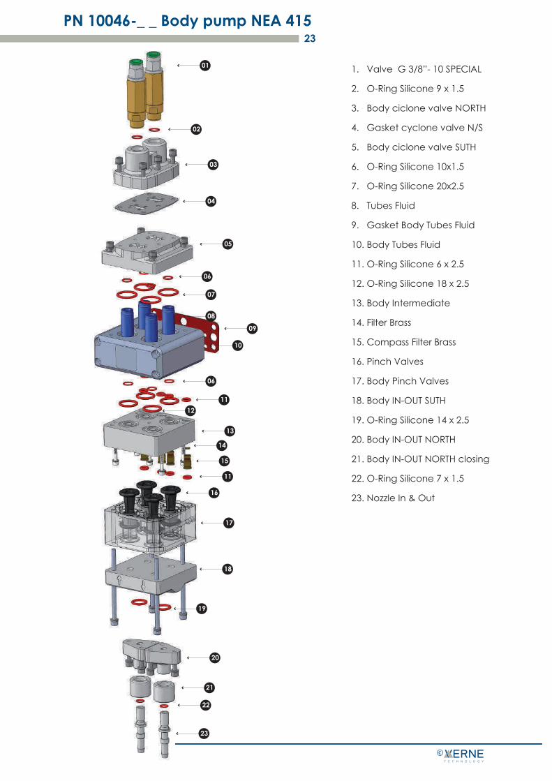
1. Valve G 3/8”- 10 SPECIAL
2. O-Ring Silicone 9 x 1.5
3. Body ciclone valve NORTH
4. Gasket cyclone valve N/S
5. Body ciclone valve SUTH
6. O-Ring Silicone 10x1.5
7. O-Ring Silicone 20x2.5
8. Tubes Fluid
9. Gasket Body Tubes Fluid
10. Body Tubes Fluid
11. O-Ring Silicone 6 x 2.5
12. O-Ring Silicone 18 x 2.5
13. Body Intermediate
14. Filter Brass
15. Compass Filter Brass
16. Pinch Valves
17. Body Pinch Valves
18. Body IN-OUT SUTH
19. O-Ring Silicone 14 x 2.5
20. Body IN-OUT NORTH
21. Body IN-OUT NORTH closing
22. O-Ring Silicone 7 x 1.5
23. Nozzle In & Out
01
03
04
06
05
06
07
08
10
11
15
12
13
11
16
17
18
19
20
21
22
23
02
14
09
alto
basso
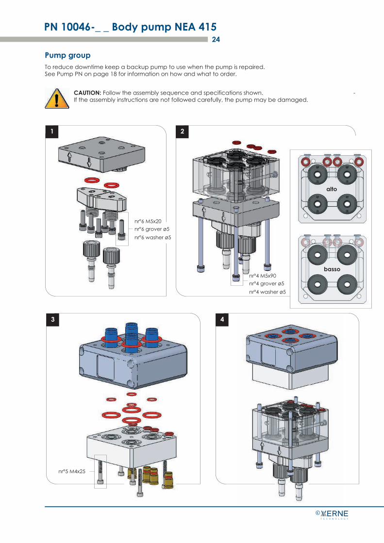
Pump group
PN 10046-_ _ Body pump NEA 41524
©
To reduce downtime keep a backup pump to use when the pump is repaired. See Pump PN on page 18 for information on how and what to order.
CAUTION: Follow the assembly sequence and specifications shown. If the assembly instructions are not followed carefully, the pump may be damaged.
-
1 2
3 4
nr°6 M5x20nr°6 grover ø5nr°6 washer ø5
nr°4 M5x90nr°4 grover ø5nr°4 washer ø5
nr°5 M4x25
PN 10046-_ _ Body pump NEA 41525
©
5 6
7
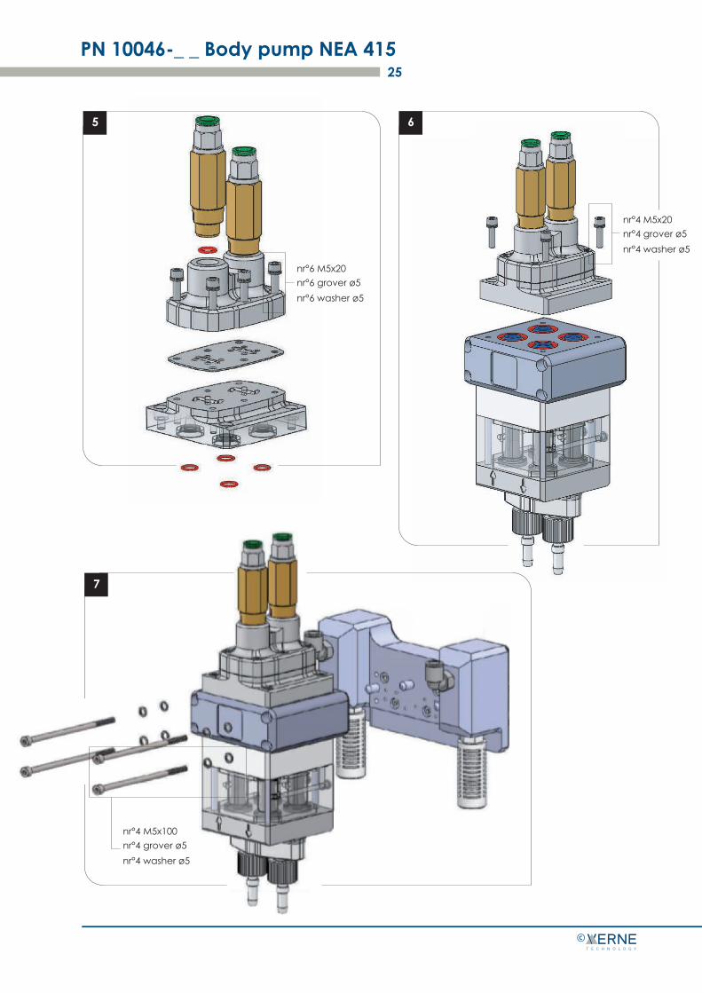
nr°6 M5x20nr°6 grover ø5nr°6 washer ø5
nr°4 M5x20nr°4 grover ø5nr°4 washer ø5
nr°4 M5x100nr°4 grover ø5nr°4 washer ø5
Replacement of the pinch valve
PN 10046-_ _ Body pump NEA 41526
©
1
5
CAUTION: Before putting the pinch valve body in a vice,
fill the jaws. Tighten the clamp just enough to hold the valve body firmly. Failure to comply may cause damage to the sleeve valve body.
NOTE: Replace the filter discs (included in the pinch valve kit) when replacing the pinch valves. Refer to item 7 of the Pump assembly procedure.
-
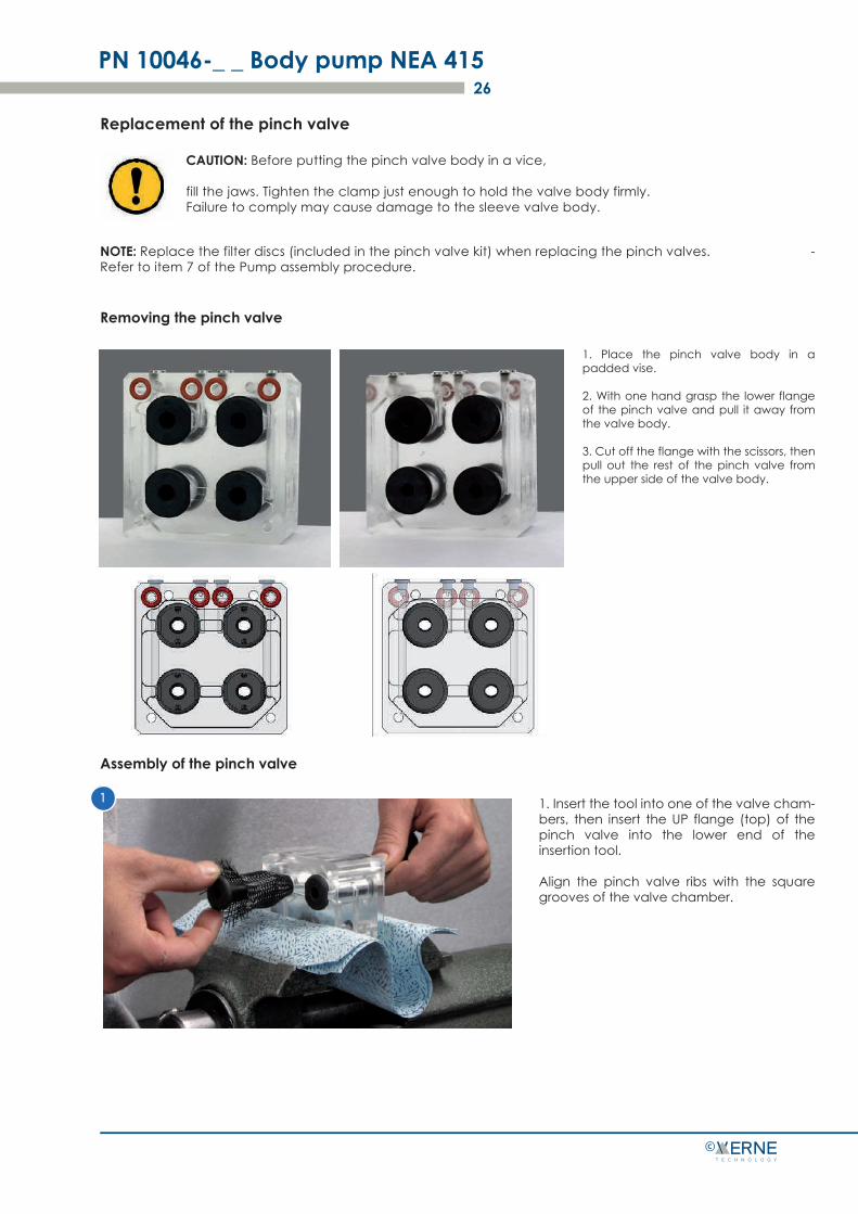
Removing the pinch valve
Assembly of the pinch valve
1
1. Place the pinch valve body in a padded vise.
2. With one hand grasp the lower flange of the pinch valve and pull it away from the valve body.
3. Cut off the flange with the scissors, then pull out the rest of the pinch valve from the upper side of the valve body.
1. Insert the tool into one of the valve cham-bers, then insert the UP flange (top) of the pinch valve into the lower end of the insertion tool.
Align the pinch valve ribs with the square grooves of the valve chamber.
PN 10046-_ _ Body pump NEA 41527
©
5
2
5
3
5
4
5
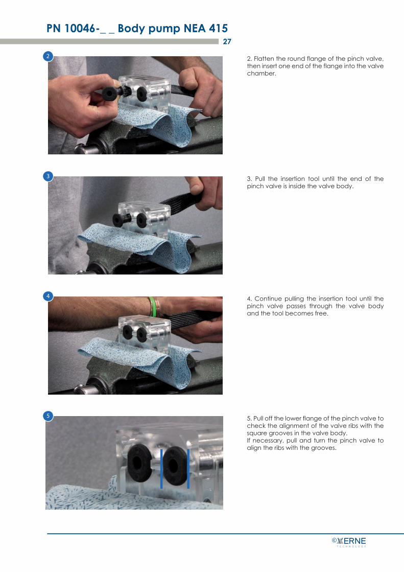
2. Flatten the round flange of the pinch valve, then insert one end of the flange into the valve chamber.
3. Pull the insertion tool until the end of the pinch valve is inside the valve body.
4. Continue pulling the insertion tool until the pinch valve passes through the valve body and the tool becomes free.
5. Pull off the lower flange of the pinch valve to check the alignment of the valve ribs with the square grooves in the valve body. If necessary, pull and turn the pinch valve to align the ribs with the grooves.
415
415
Low pressure dense phase transport system NEA 415 28
©
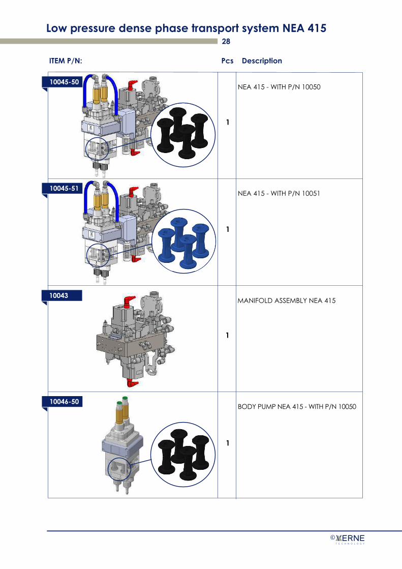
ITEM P/N: Pcs Description
10045-50NEA 415 - WITH P/N 10050
10045-51NEA 415 - WITH P/N 10051
10046-50BODY PUMP NEA 415 - WITH P/N 10050
1
1
1
10043MANIFOLD ASSEMBLY NEA 415
1
Low pressure dense phase transport system NEA 415 29
©
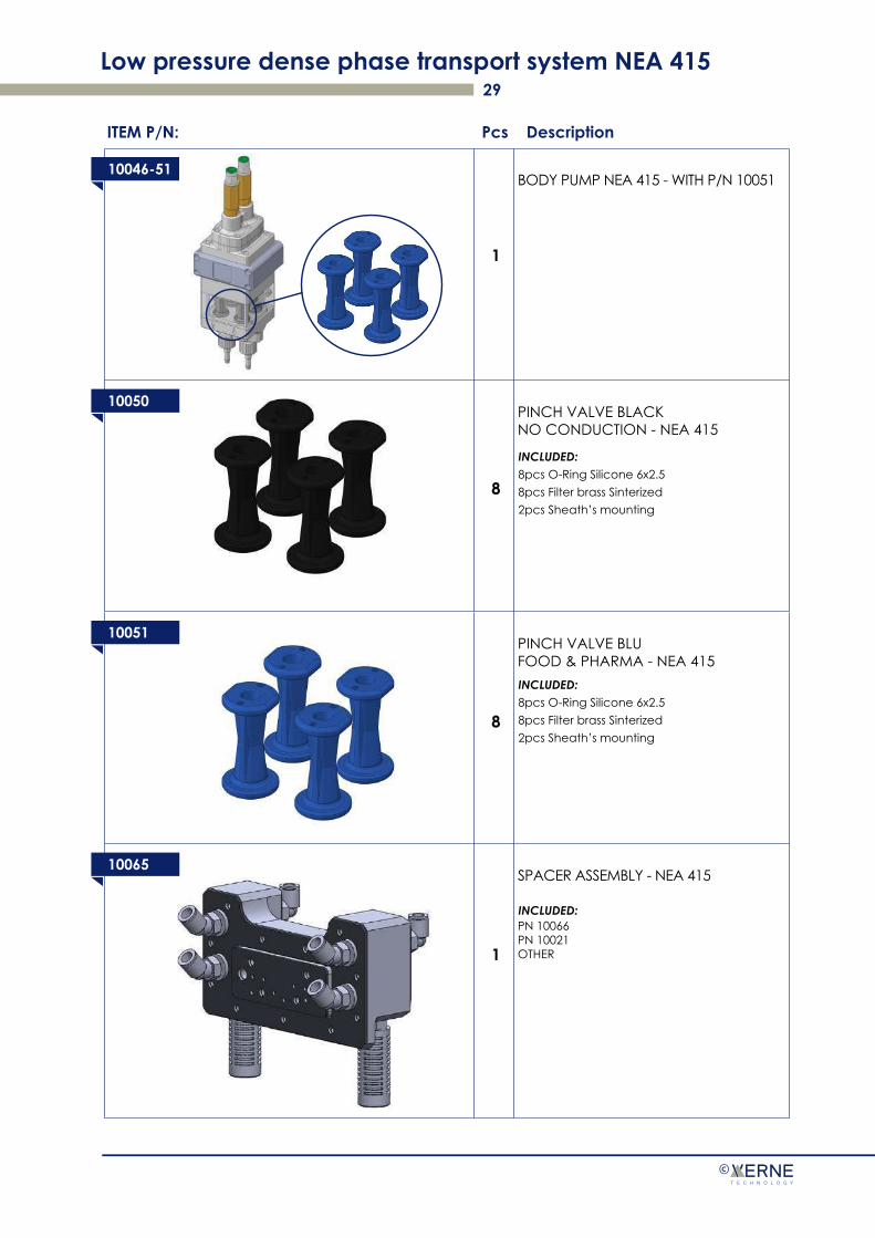
10046-51BODY PUMP NEA 415 - WITH P/N 10051
ITEM P/N: Pcs Description
10050PINCH VALVE BLACKNO CONDUCTION - NEA 415
10051PINCH VALVE BLUFOOD & PHARMA - NEA 415
10065SPACER ASSEMBLY - NEA 415
PN 10066PN 10021OTHER
1
8
8
1
INCLUDED:8pcs O-Ring Silicone 6x2.58pcs Filter brass Sinterized 2pcs Sheath’s mounting
INCLUDED:8pcs O-Ring Silicone 6x2.58pcs Filter brass Sinterized 2pcs Sheath’s mounting
INCLUDED:
Low pressure dense phase transport system NEA 415 30
©
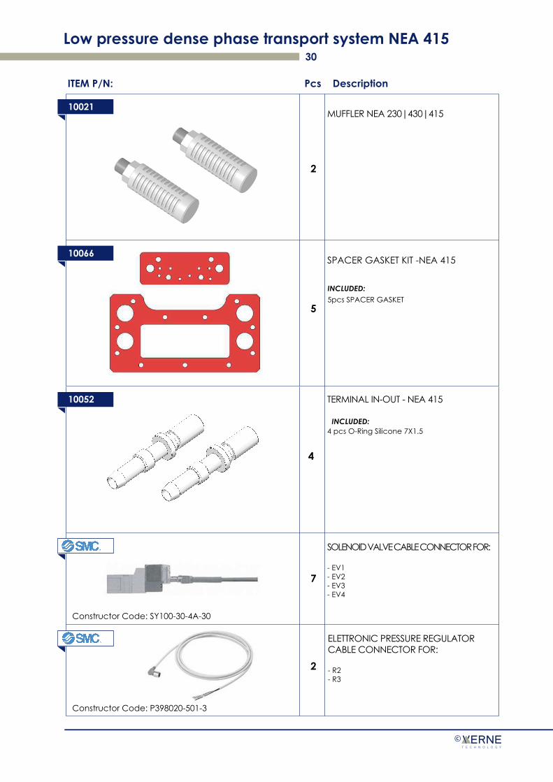
10021MUFFLER NEA 230|430|415
ITEM P/N: Pcs Description
10066SPACER GASKET KIT -NEA 415
10052 TERMINAL IN-OUT - NEA 415
4 pcs O-Ring Silicone 7X1.5
5
4
INCLUDED:5pcs SPACER GASKET
INCLUDED:
2
SOLENOID VALVE CABLE CONNECTOR FOR:
- EV1- EV2- EV3- EV4
7
ELETTRONIC PRESSURE REGULATOR CABLE CONNECTOR FOR:
- R2- R3
2
Constructor Code: SY100-30-4A-30
Constructor Code: P398020-501-3
Low pressure dense phase transport system NEA 415 31
©
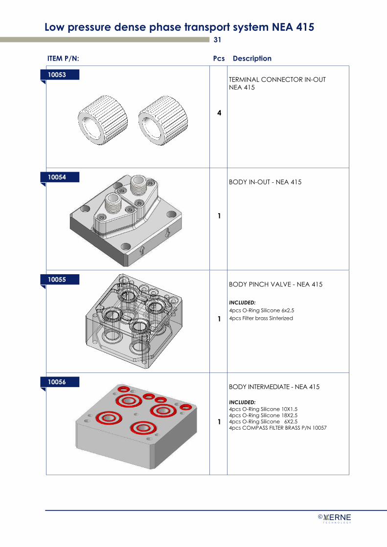
10053TERMINAL CONNECTOR IN-OUT NEA 415
ITEM P/N: Pcs Description
10054BODY IN-OUT - NEA 415
10055BODY PINCH VALVE - NEA 415
10056BODY INTERMEDIATE - NEA 415
4pcs O-Ring Silicone 10X1.54pcs O-Ring Silicone 18X2.54pcs O-Ring Silicone 6X2.54pcs COMPASS FILTER BRASS P/N 10057
4
1
1
1
INCLUDED:4pcs O-Ring Silicone 6x2.54pcs Filter brass Sinterized
INCLUDED:
Low pressure dense phase transport system NEA 415 32
©
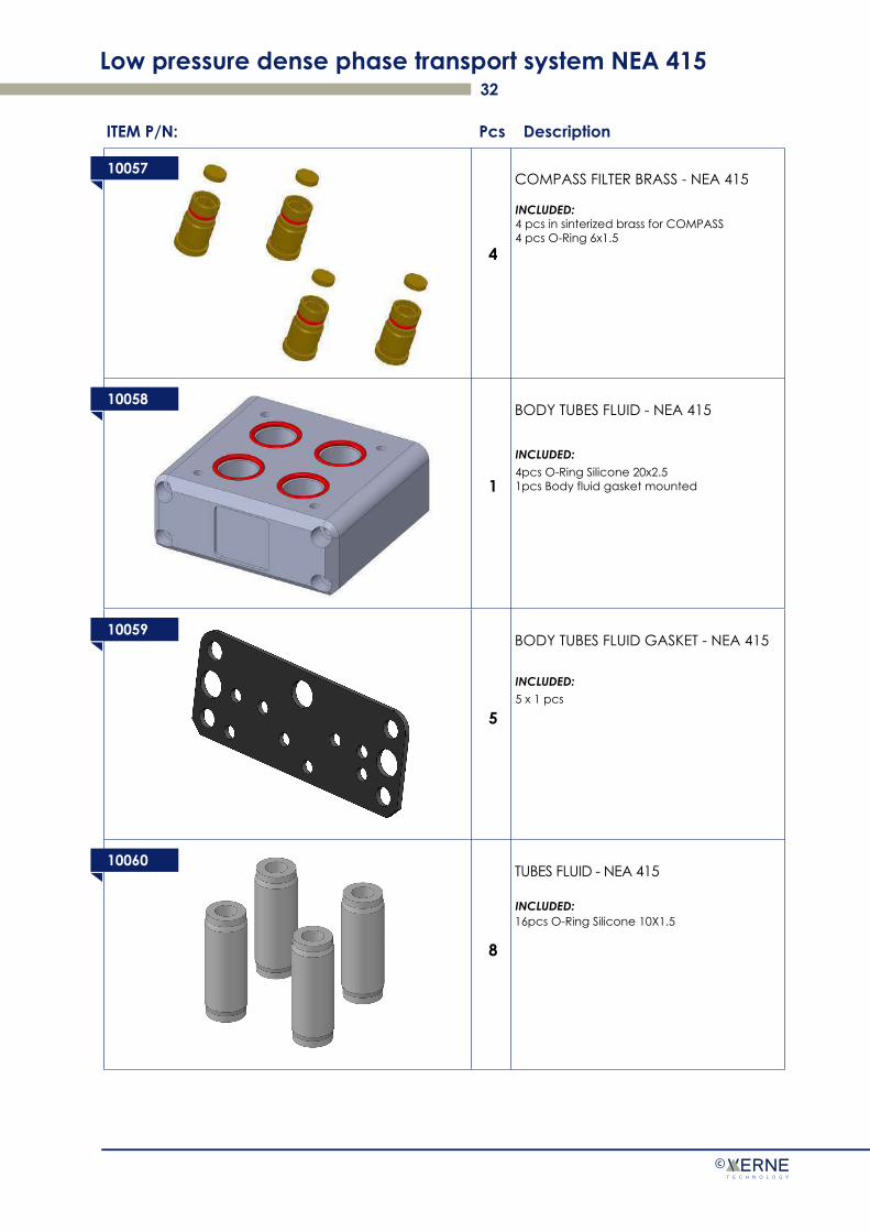
10057COMPASS FILTER BRASS - NEA 415
ITEM P/N: Pcs Description
10058BODY TUBES FLUID - NEA 415
10059BODY TUBES FLUID GASKET - NEA 415
10060TUBES FLUID - NEA 415
16pcs O-Ring Silicone 10X1.5
4
1
5
8
INCLUDED:4pcs O-Ring Silicone 20x2.51pcs Body fluid gasket mounted
INCLUDED:5 x 1 pcs
INCLUDED:
INCLUDED:4 pcs in sinterized brass for COMPASS4 pcs O-Ring 6x1.5
Low pressure dense phase transport system NEA 415 33
©
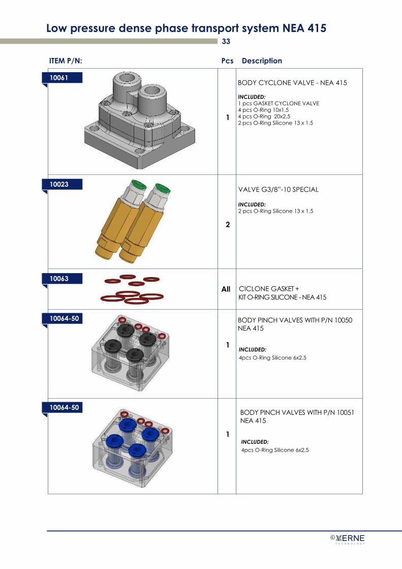
10061BODY CYCLONE VALVE - NEA 415
ITEM P/N: Pcs Description
10023
10063
10064-50 BODY PINCH VALVES WITH P/N 10050NEA 415
1
2
1
INCLUDED:1 pcs GASKET CYCLONE VALVE4 pcs O-Ring 10x1.54 pcs O-Ring 20x2.52 pcs O-Ring Silicone 13 x 1.5
VALVE G3/8”-10 SPECIAL
INCLUDED:2 pcs O-Ring Silicone 13 x 1.5
CICLONE GASKET +All
10064-50
INCLUDED:4pcs O-Ring Silicone 6x2.5
BODY PINCH VALVES WITH P/N 10051NEA 415
INCLUDED:4pcs O-Ring Silicone 6x2.5
1
KIT O-RING SILICONE - NEA 415
Low pressure dense phase transport system NEA 415 34
©
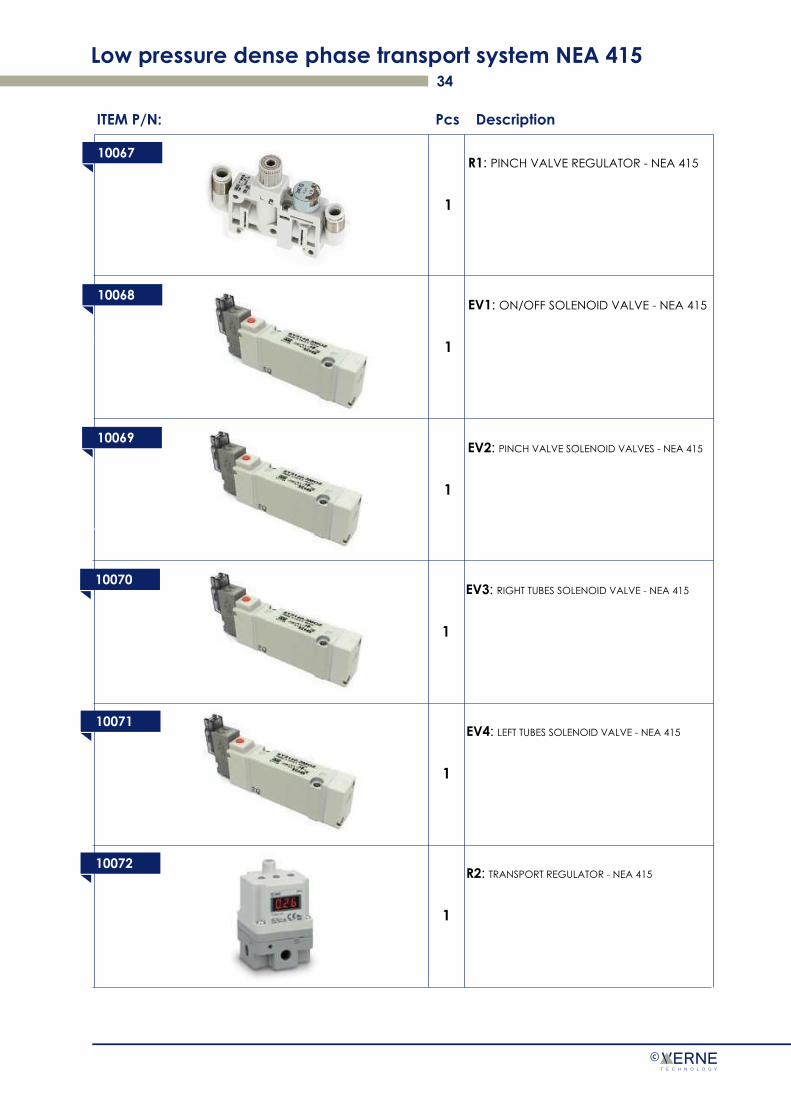
10067R1: PINCH VALVE REGULATOR - NEA 415
ITEM P/N: Pcs Description
10063
1
10068EV1: ON/OFF SOLENOID VALVE - NEA 415
1
10069EV2: PINCH VALVE SOLENOID VALVES - NEA 415
1
10070EV3: RIGHT TUBES SOLENOID VALVE - NEA 415
1
10071EV4: LEFT TUBES SOLENOID VALVE - NEA 415
1
10072R2: TRANSPORT REGULATOR - NEA 415
1

Low pressure dense phase transport system NEA 415 35
©
10073R3: RECOVERY REGULATOR - NEA 415
ITEM P/N: Pcs Description
10063
1
10023VACUUM GENERATOR -NEA 230|430|415
2
10062KIT FITTINGS|PURGE -NEA 415
1INCLUDED:
All fittings
10070
10071
Low pressure dense phase transport system NEA 415
©
DECLARATION OF CONFORMITYModel: NEA 415 low pressure dense phase transport system
Principle:
Note: The year of manufacture of the appliance appears in the serial number. "PL00171" indicates that the appliance was manufactured in 2017, the final "1" indicates the lot of the year.
Date: 01 Dicembre 2017
Verne Technology S.r.l.CEOCarlo Perillo
The installation and commissioning of NEA 415 PN 10045 -__ and subgroups PN 10043, PN 10065 and PN10046 -__ must be carried out in compliance with the international and national regulations of the country of use.
NEA 415 PN 10045 -__ and subgroups PN 10043, PN 10065 and PN 10046 -__, must be considered as compo-nents, since according to the machine directive it is neither a machine nor an appliance ready for use.
It is therefore up to the end user to ensure the conformity of his machine in the applicable regulations.
Verne Technology srl declines all responsibility for damage to persons, animals or objects due to the use of NEA 415 PN 10045 -__ and subgroups PN 10043, PN 10065 and PN 10046 -__, not foreseen or that do not comply with the international and national standards of the country of use.
The Products and materials presented in this manual are susceptible at any time of evolution or modifica-tion.