enhance and increase your recovery – flexibility to … - tony lain… · enhance and increase...
TRANSCRIPT

Enhance and Increase Your Recovery Enhance and Increase Your Recovery Enhance and Increase Your Recovery –FLEXIBILITY TO YOUR FIELD DEVELOPMENT
Enhance and Increase Your Recovery –FLEXIBILITY TO YOUR FIELD DEVELOPMENT
Tony J. A. Laing – UK Regional Manager
Agenda
Objectives
Introduction to why boosting
Where boosting is today
An awareness of what more can be achieved in recovery (dual boost)
Some case studies
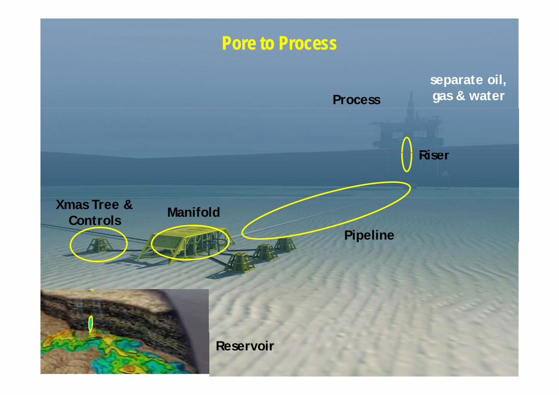
Pore to ProcessPore to Process
Processseparate oil, gas & water
RiserRiser
Pipeline
Xmas Tree &Controls Manifold
Reservoir
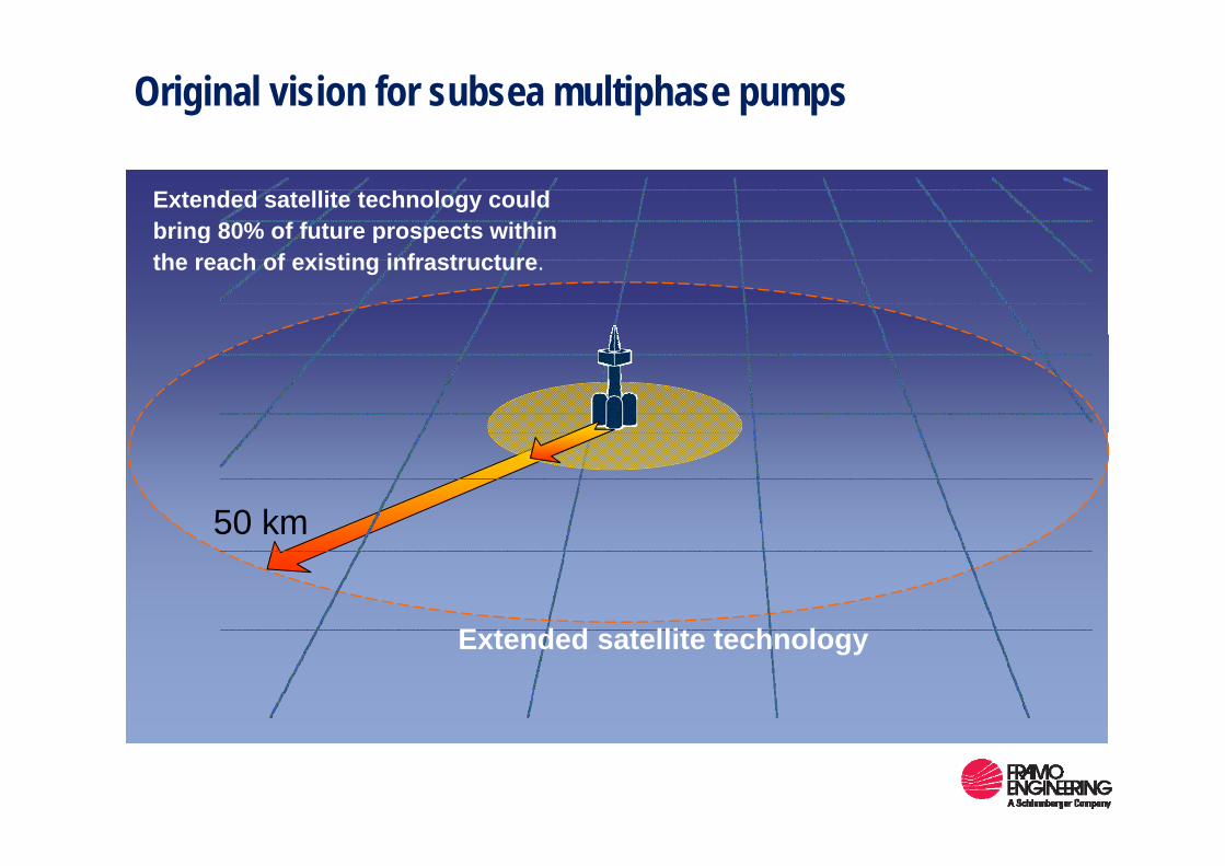
Original vision for subsea multiphase pumps
Extended satellite technology couldbring 80% of future prospects withinbring 80% of future prospects withinthe reach of existing infrastructure.
50 km
E t d d t llit t h l
50 km
Extended satellite technology
4
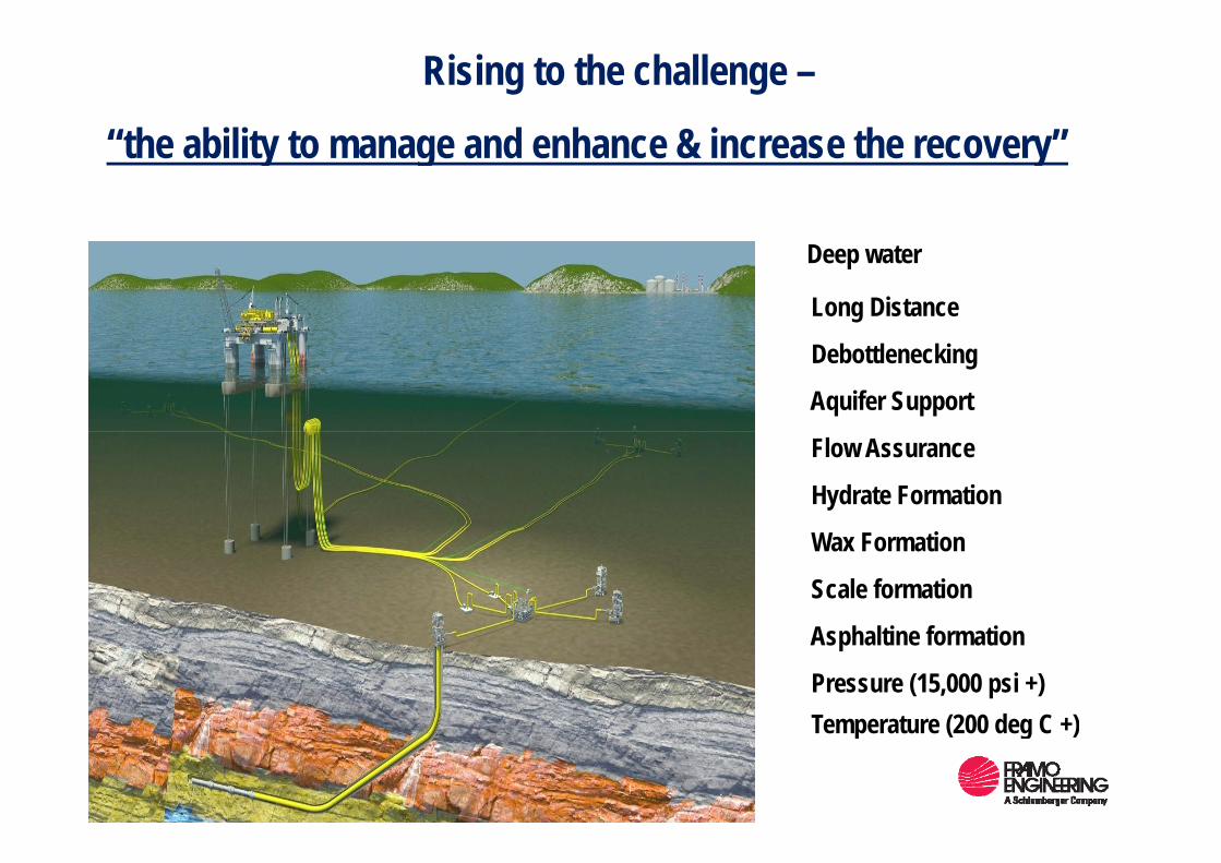
Rising to the challenge –
“the ability to manage and enhance & increase the recovery”“the ability to manage and enhance & increase the recovery”
Deep water
Long Distance
Debottlenecking
Aquifer Support
Flow Assurance
Hydrate Formation
Wax Formation
Scale formation
A h lti f tiAsphaltine formation
Pressure (15,000 psi +)Temperature (200 deg C +)Temperature (200 deg C +)
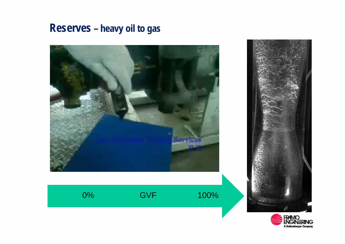
Reserves – heavy oil to gas
100%GVF0%
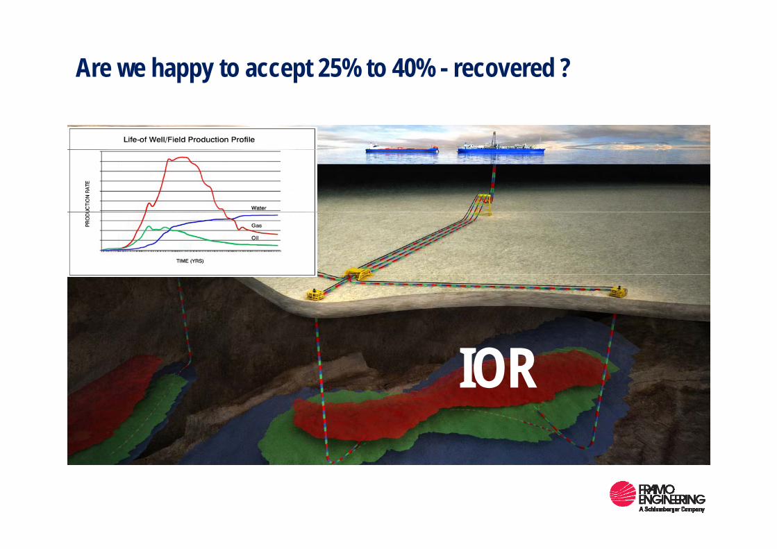
Are we happy to accept 25% to 40% - recovered ?
IOR
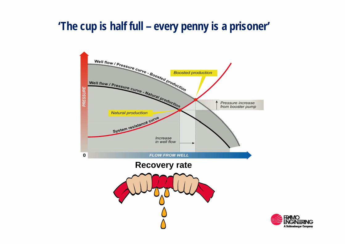
‘The cup is half full – every penny is a prisoner’
Recovery rate
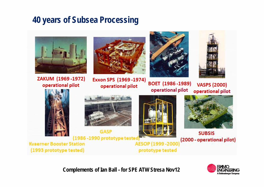
40 years of Subsea Processing
Complements of Ian Ball - for SPE ATW Stresa Nov12
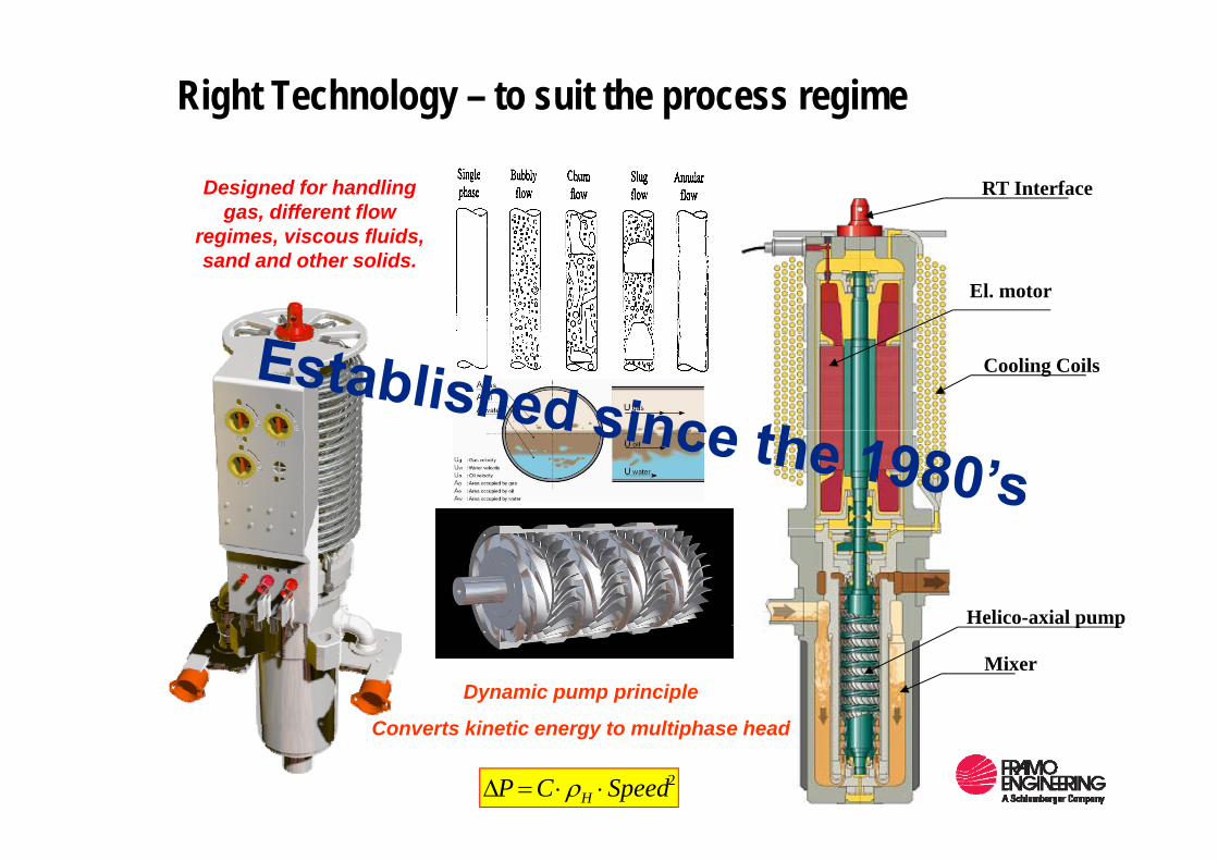
Right Technology – to suit the process regime
RT InterfaceDesigned for handling gas, different flow
regimes viscous fluids
El. motor
regimes, viscous fluids, sand and other solids.
Cooling Coils
Helico-axial pump
Mixer
p p
Dynamic pump principle
C t ki ti t lti h h dConverts kinetic energy to multiphase head
2SpeedCP H ⋅⋅=Δ ρ
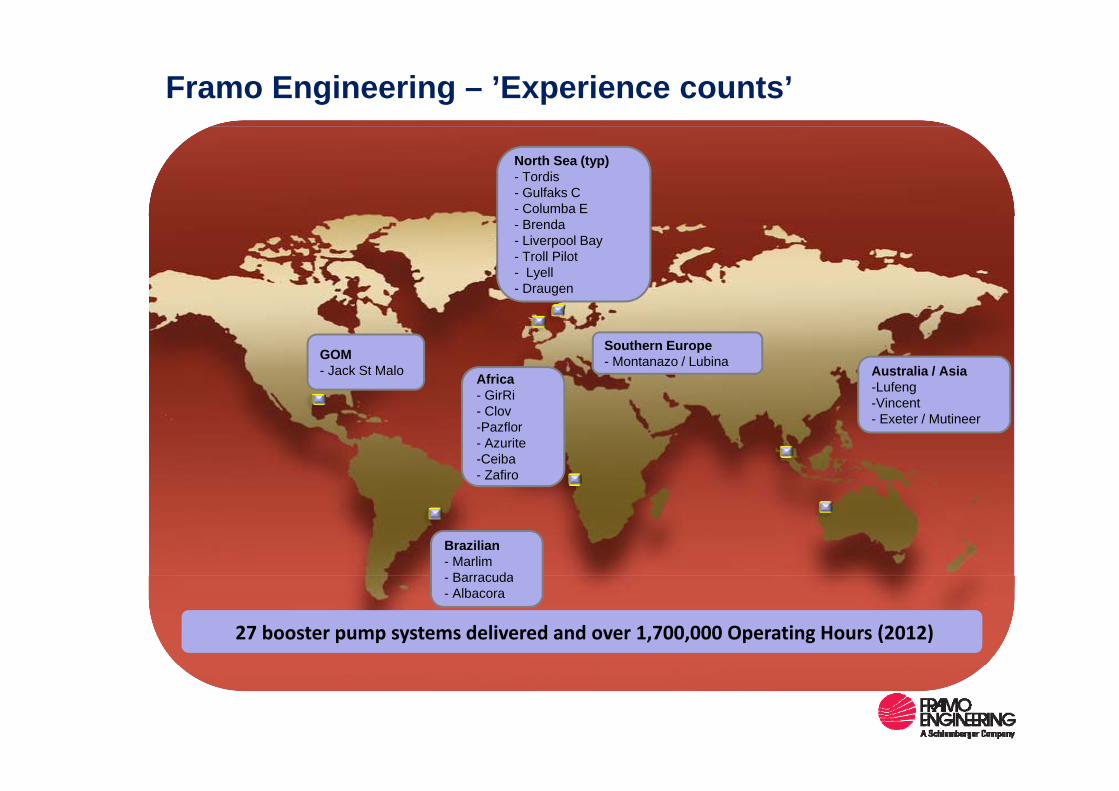
Framo Engineering – ’Experience counts’
North Sea (typ)- Tordis- Gulfaks C- Columba E- Brenda- Liverpool Bay- Troll Pilot- Lyell- Draugen
Africa - GirRi
Australia / Asia-Lufeng
Southern Europe- Montanazo / LubinaGOM
- Jack St Malo
- GirRi- Clov-Pazflor- Azurite-Ceiba- Zafiro
-Vincent- Exeter / Mutineer
Brazilian- Marlim
Barracuda
27 booster pump systems delivered and over 1,700,000 Operating Hours (2012)
- Barracuda- Albacora
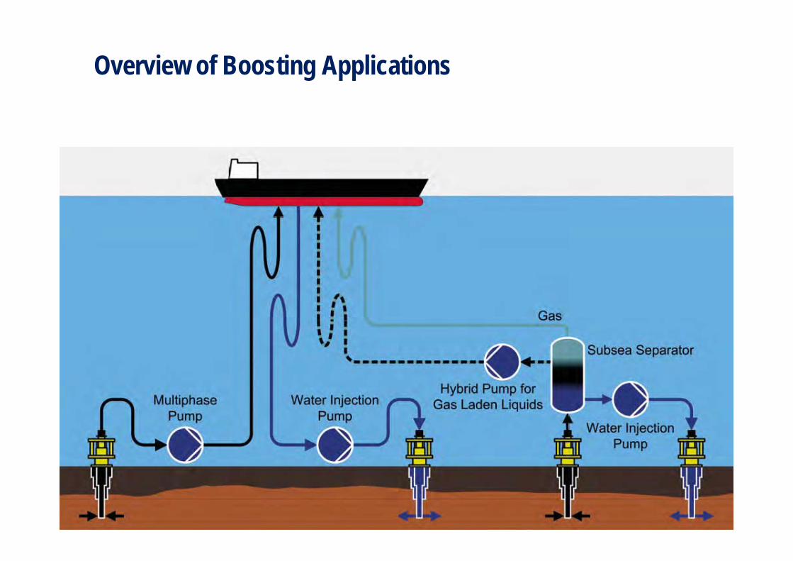
Overview of Boosting Applications
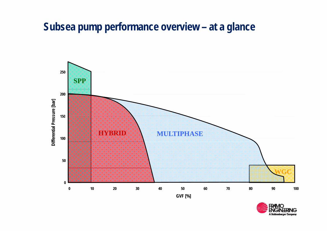
Subsea pump performance overview – at a glance
SPP250
150
200
sure
[bar
]
MULTIPHASE100
150
ffere
ntial
Pre
ss
HYBRID
50
Dif
WGC0
0 10 20 30 40 50 60 70 80 90 100
GVF [%]
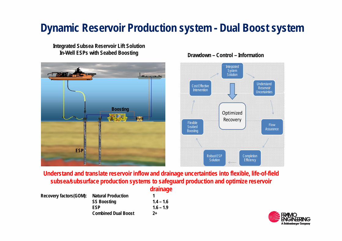
Dynamic Reservoir Production system - Dual Boost system
I t t d
Drawdown – Control – InformationIntegrated Subsea Reservoir Lift Solution
In-Well ESPs with Seabed Boosting
Integrated System Solution
Understand Reservoir
UncertaintiesCost Effective Intervention Uncertainties
Optimized Recovery
Boosting
Flow Assurance
Flexible Seabed Boosting
Recovery
Completion Efficiency
Robust ESP Solution
ESP
Understand and translate reservoir inflow and drainage uncertainties into flexible, life-of-field Understand and translate reservoir inflow and drainage uncertainties into flexible, life of field subsea/subsurface production systems to safeguard production and optimize reservoir
drainageRecovery factors(GOM): Natural Production 1
SS Boosting 1.4 – 1.6SS Boosting 1.4 1.6ESP 1.6 – 1.9Combined Dual Boost 2+
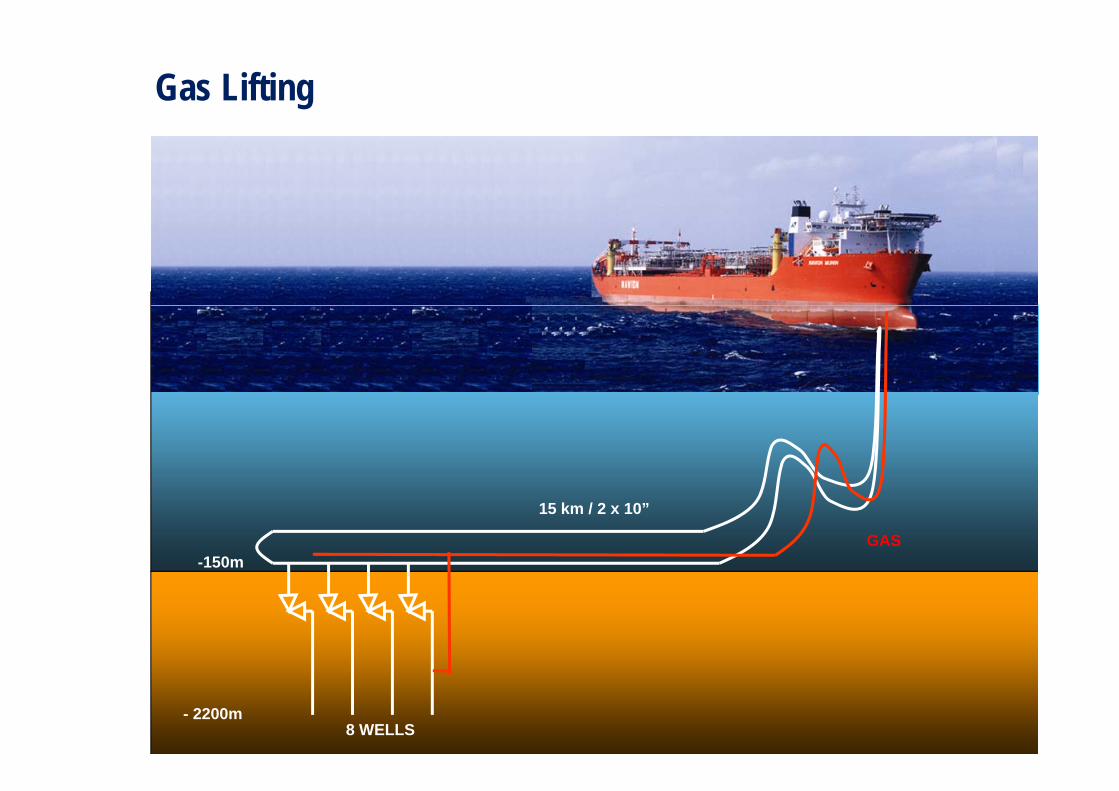
Gas Lifting
0 m
-150m
15 km / 2 x 10”
GAS
- 2200m8 WELLS

Case Study Gas Lifting and Boosting
0 m
-150m
5 km / 2 x 6”POWER
15 km
2 x 10”
- 2200m8 WELLS
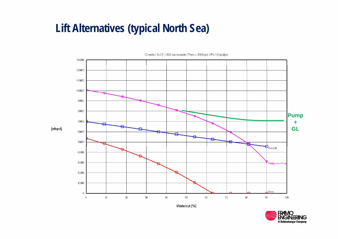
Lift Alternatives (typical North Sea)
Pump+
GL

Schlumberger / Framo Dual Lift System Simulation suggests that optimal technique for maximum recovery is
a combination of in well ESP’s coupled with seabed boosting
++
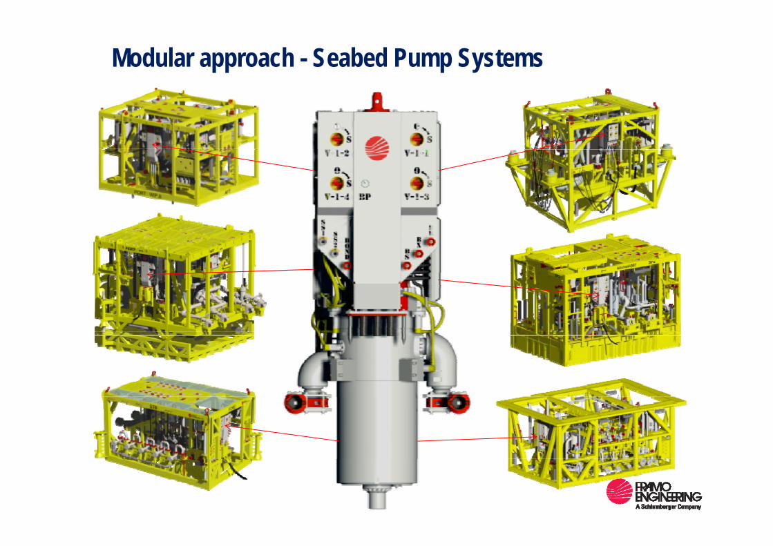
Modular approach - Seabed Pump Systems
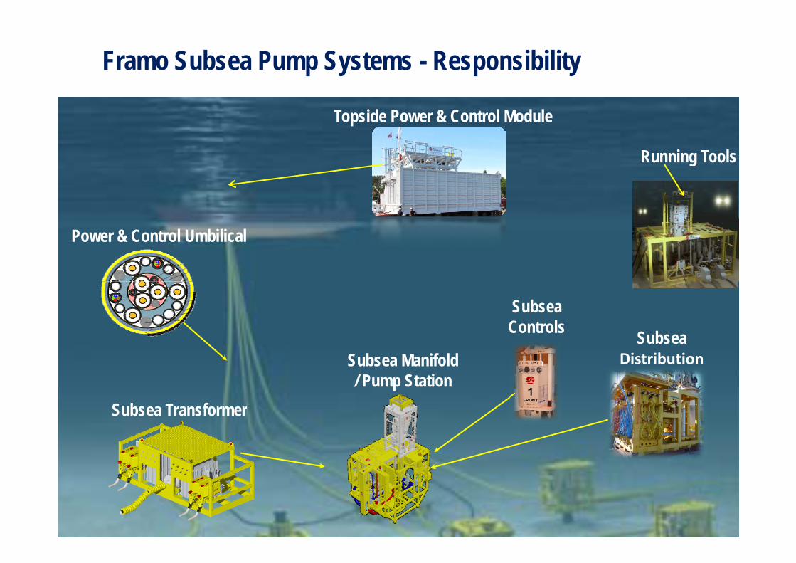
Framo Subsea Pump Systems - Responsibility
Topside Power & Control Module
Running ToolsRunning Tools
Power & Control Umbilical
SubseaControls Subsea
Distribution
Subsea Transformer
Subsea Manifold/ Pump Station
Subsea Transformer
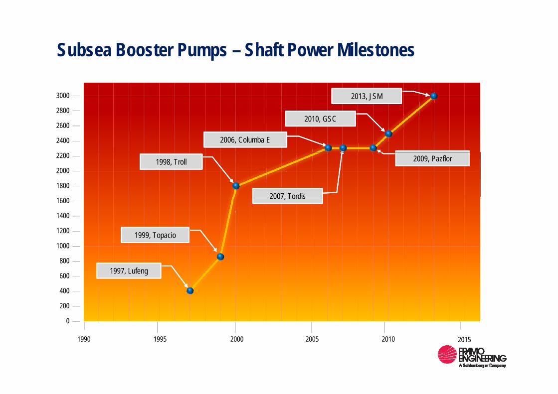
Subsea Booster Pumps – Shaft Power Milestones
3000 2013, JSM
2400
2600
28002010, GSC
2006, Columba E
1800
2000
22001998, Troll
2007 Tordis
2009, Pazflor
1200
1400
1600 2007, Tordis
1999, Topacio
600
800
1000
1997, Lufeng
200
400
0
1990 2000 201020051995 2015
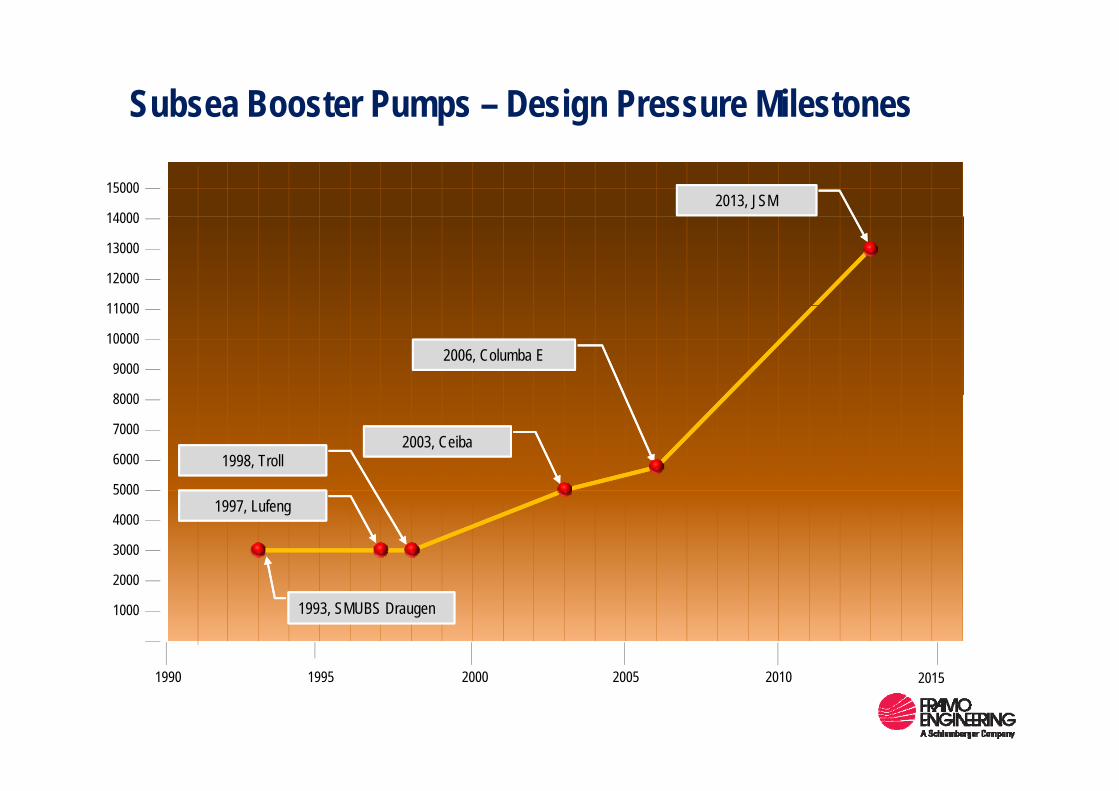
Subsea Booster Pumps – Design Pressure Milestones
14000
150002013, JSM
11000
12000
13000
14000
8000
9000
10000
11000
2006, Columba E
5000
6000
7000
8000
1998, Troll2003, Ceiba
2000
3000
4000
50001997, Lufeng
1000
2000
1993, SMUBS Draugen
1990 2000 201020051995 2015
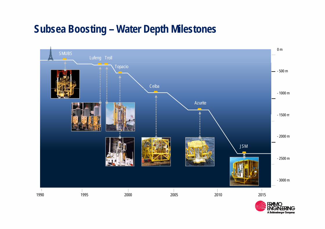
Subsea Boosting – Water Depth Milestones0 m
TrollLufengSMUBS
- 500 m
Ceiba
Topacio
- 1000 m
1500 m
Azurite
- 1500 m
- 2000 m
- 2500 m
JSM
- 3000 m
1990 2000 201020051995 2015
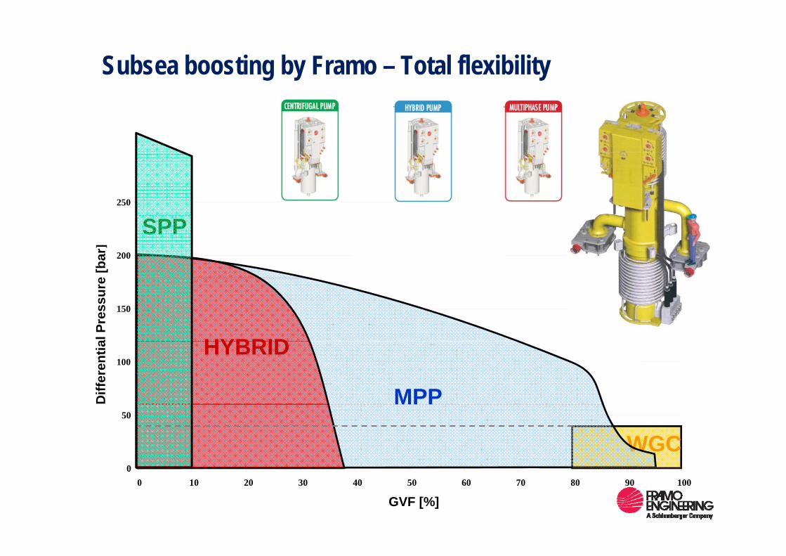
Subsea boosting by Framo – Total flexibility
250
SPP200
e [b
ar]
150
al P
ress
ure
HYBRID100
Diff
eren
tia HYBRID
MPP
WGC0
50MPP
00 10 20 30 40 50 60 70 80 90 100
GVF [%]
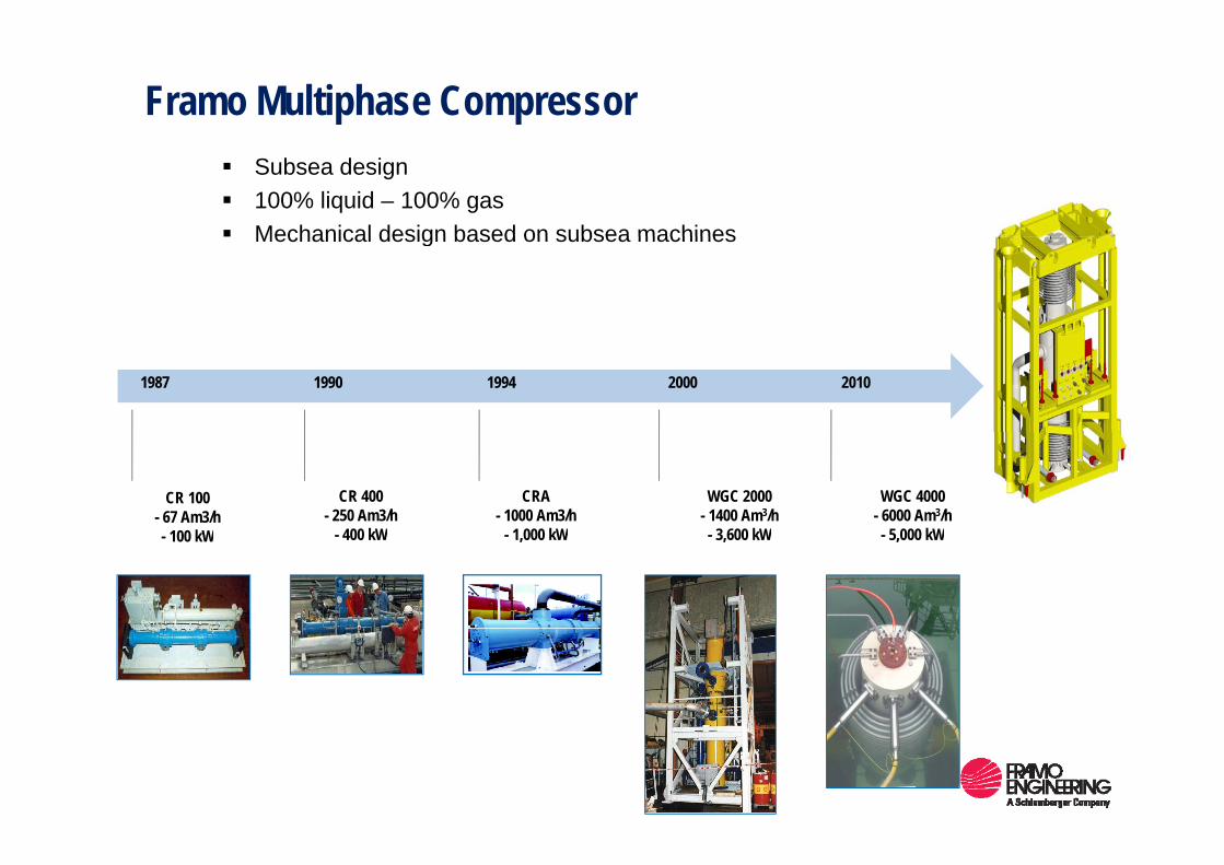
Framo Multiphase Compressor Subsea design100% liquid – 100% gasMechanical design based on subsea machinesMechanical design based on subsea machines
1987 1990 1994 2000 2010
CR 100- 67 Am3/h
100 kW
CR 400- 250 Am3/h
400 kW
CRA- 1000 Am3/h
1 000 kW
WGC 2000- 1400 Am3/h
3 600 kW
WGC 4000- 6000 Am3/h
5 000 kW- 100 kW - 400 kW - 1,000 kW - 3,600 kW - 5,000 kW
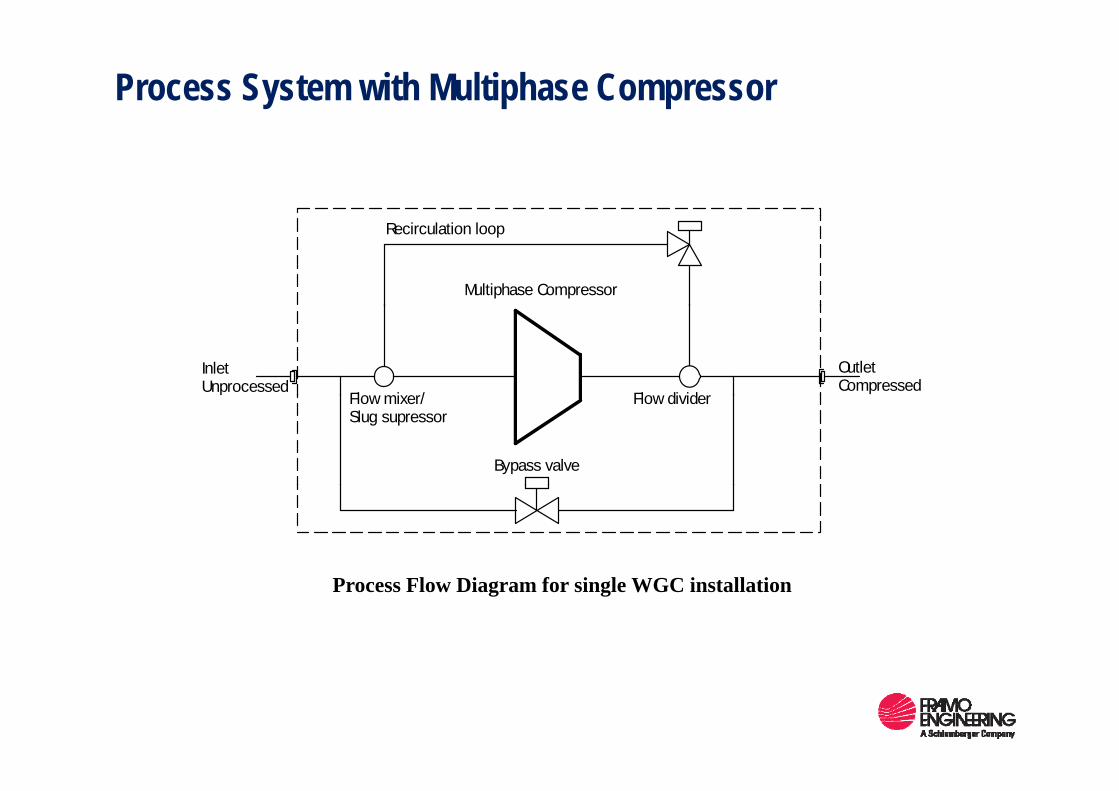
Process System with Multiphase Compressor
Multiphase Compressor
Recirculation loop
InletUnprocessed
OutletCompressed
Flow mixer/ Flow divider
Bypass valve
Flow mixer/Slug supressor
Flow divider
Process Flow Diagram for single WGC installation
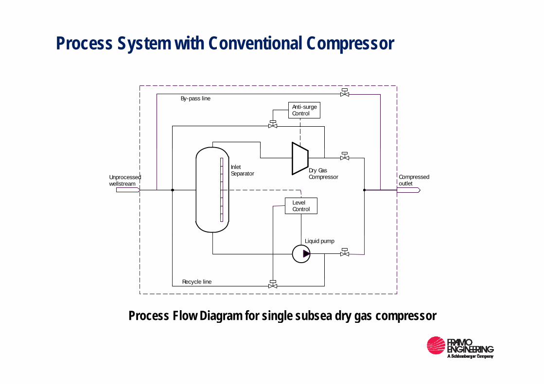
Process System with Conventional Compressor
A tiBy-pass line
Anti-surgeControl
Unprocessedwellstream
Compressedoutlet
InletSeparator Dry Gas
Compressor
LevelControl
Liquid pump
Recycle line
Process Flow Diagram for single subsea dry gas compressor
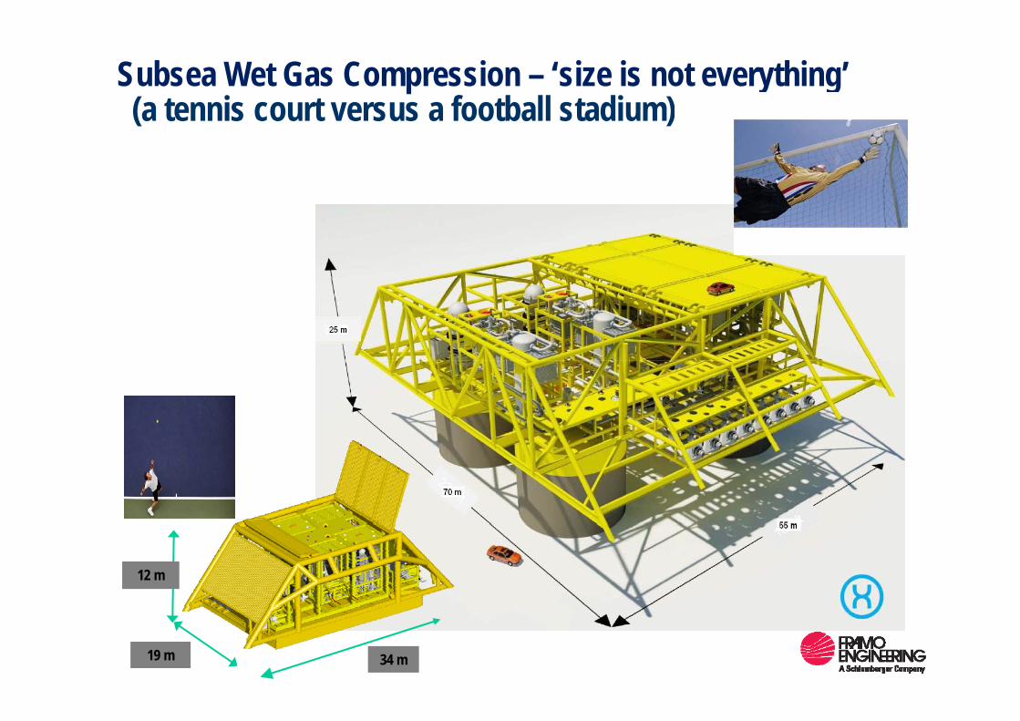
Subsea Wet Gas Compression – ‘size is not everything’(a tennis court versus a football stadium)(a tennis court versus a football stadium)
12 m
34 m19 m

Wet Gas Compression (WGC)
GullfaksKey data – WGC Module:
A
B C
Gullfaks2 x 1200-4500 RPM 2 x 2.5 MW6000 m3/h32 bar dPHeight < 8 metersFootprint 5x4 meters
GullveigK
DE
FM
L G
Footprint 5x4 meters
L GGullfaks Sør
Gas pipe
N
Gas pipe
JI
H
Rimfaks
Skinfaks
N5
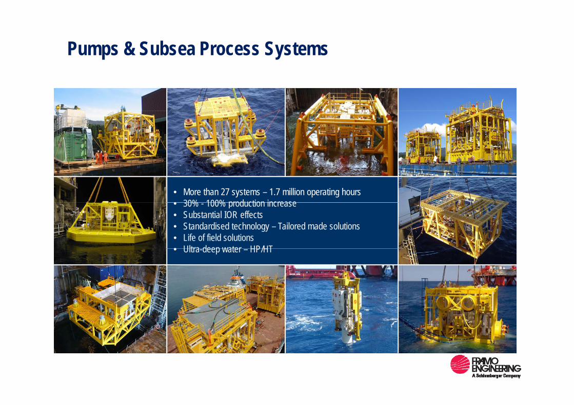
Pumps & Subsea Process Systems
• More than 27 systems – 1.7 million operating hours• 30% 100% production increase• 30% - 100% production increase• Substantial IOR effects• Standardised technology – Tailored made solutions • Life of field solutions • Ultra deep water HP/HT• Ultra-deep water – HP/HT
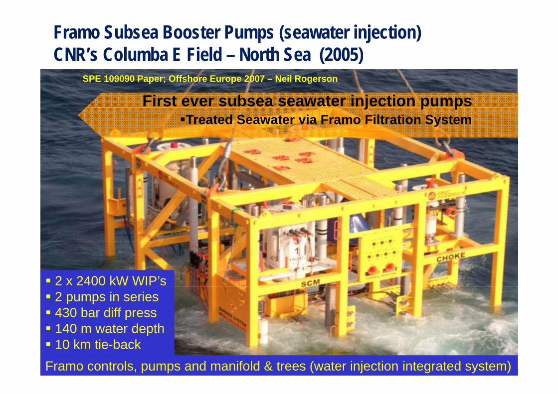
Framo Subsea Booster Pumps (seawater injection) CNR’s Columba E Field – North Sea (2005)( )
First ever subsea seawater injection pumpsSPE 109090 Paper; Offshore Europe 2007 – Neil Rogerson
j p pTreated Seawater via Framo Filtration System
2 x 2400 kW WIP’s2 pumps in series430 bar diff press140 m water depth140 m water depth10 km tie-back
Framo controls, pumps and manifold & trees (water injection integrated system)

Framo Subsea Booster Pumps (production and boosting)Premier Oil (Oilexco) Brenda Field – North Sea (2006)Premier Oil (Oilexco) Brenda Field North Sea (2006)
Multiphase PumpMultiphase Meter Multiport Selector Manifold
Subsea Control ModulesBoosting, Manifold & Trees
Improved Reservoir Management Increased Production Increased Control
CapacityIncreased Flexibility
150 m water depth10 / 20 km tie-back1100 kW Power System
Framo Production & Boosting SystemOTC – 17899 Paper; OTC 2006 - Mike Coulthard

Barracuda Subsea Multiphase Pump
P. 48 FPSOIntegrated
Power/Control Umbilical
Production Flow Line Service/Gas Inj. Line
Prod. XTMain Data:
MPP Station
Main Data:Liquid flow rate: 3000 m3/dPump diff. press.: 60 – 70 barGVF 60% MPP Station
Water depth: 1060 m
GVF: 60%Motor shaft power: 1.5 MW
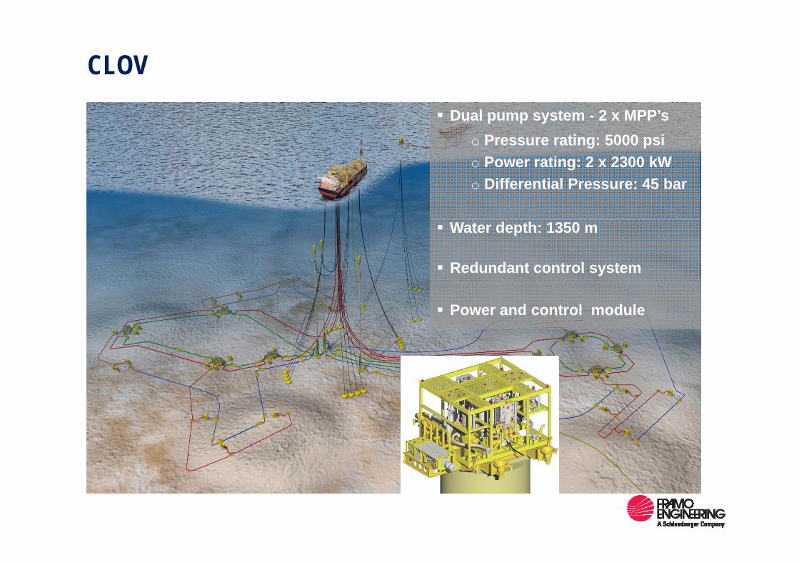
CLOVDual pump system - 2 x MPP’s
o Pressure rating: 5000 psio Power rating: 2 x 2300 kWo Differential Pressure: 45 bar
Water depth: 1350 m
Redundant control system
Power and control module
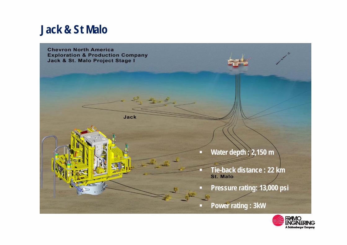
Jack & St Malo
W t d th 2 150 Water depth : 2,150 m
Tie-back distance : 22 km
Pressure rating: 13,000 psi
Power rating : 3kWPower rating : 3kW
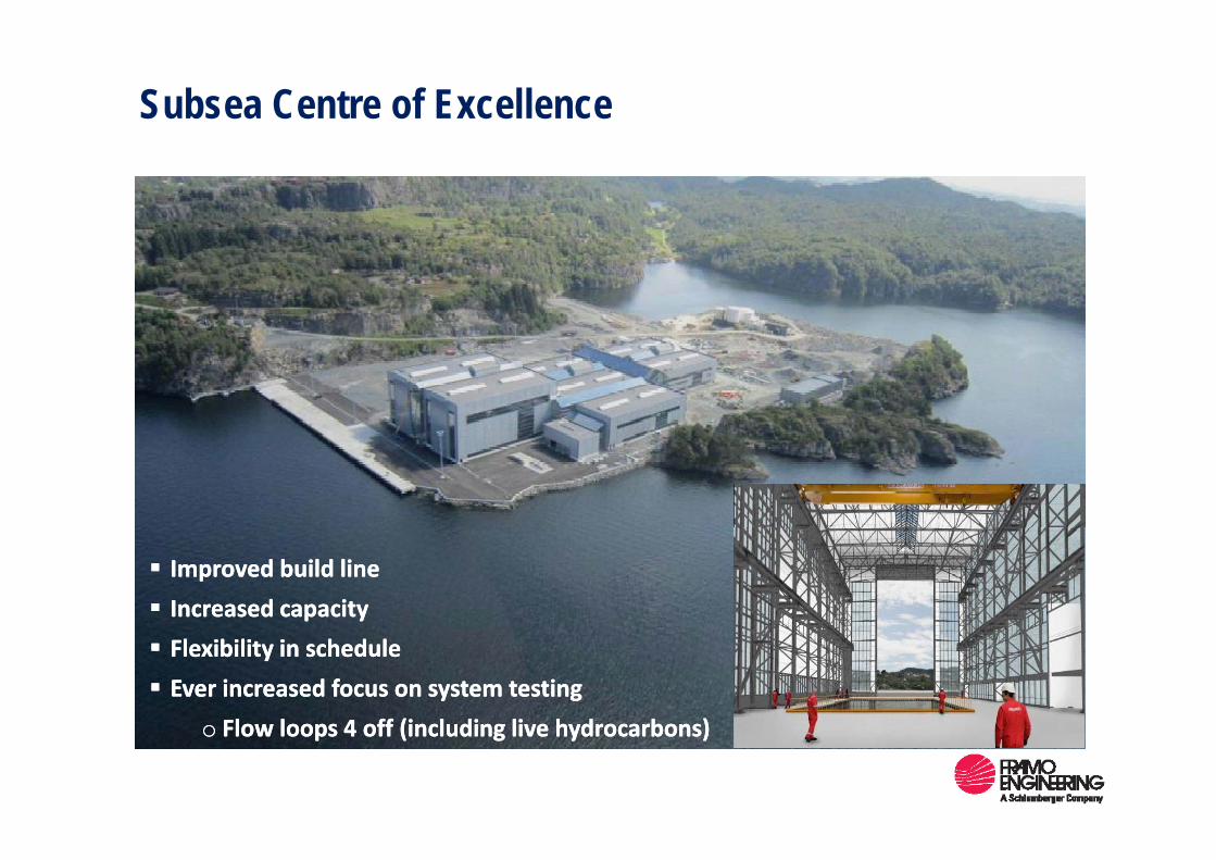
Subsea Centre of Excellence
ImprovedImproved buildbuild linelineIncreasedIncreased capacitycapacityFlexibilityFlexibility in in schedulescheduleEver Ever increasedincreased focusfocus onon system system testingtesting
Fl l 4 ff (i l di li h d b )Fl l 4 ff (i l di li h d b )oo Flow loops 4 off (including live hydrocarbons)Flow loops 4 off (including live hydrocarbons)
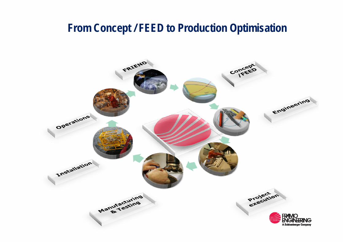
From Concept / FEED to Production Optimisation
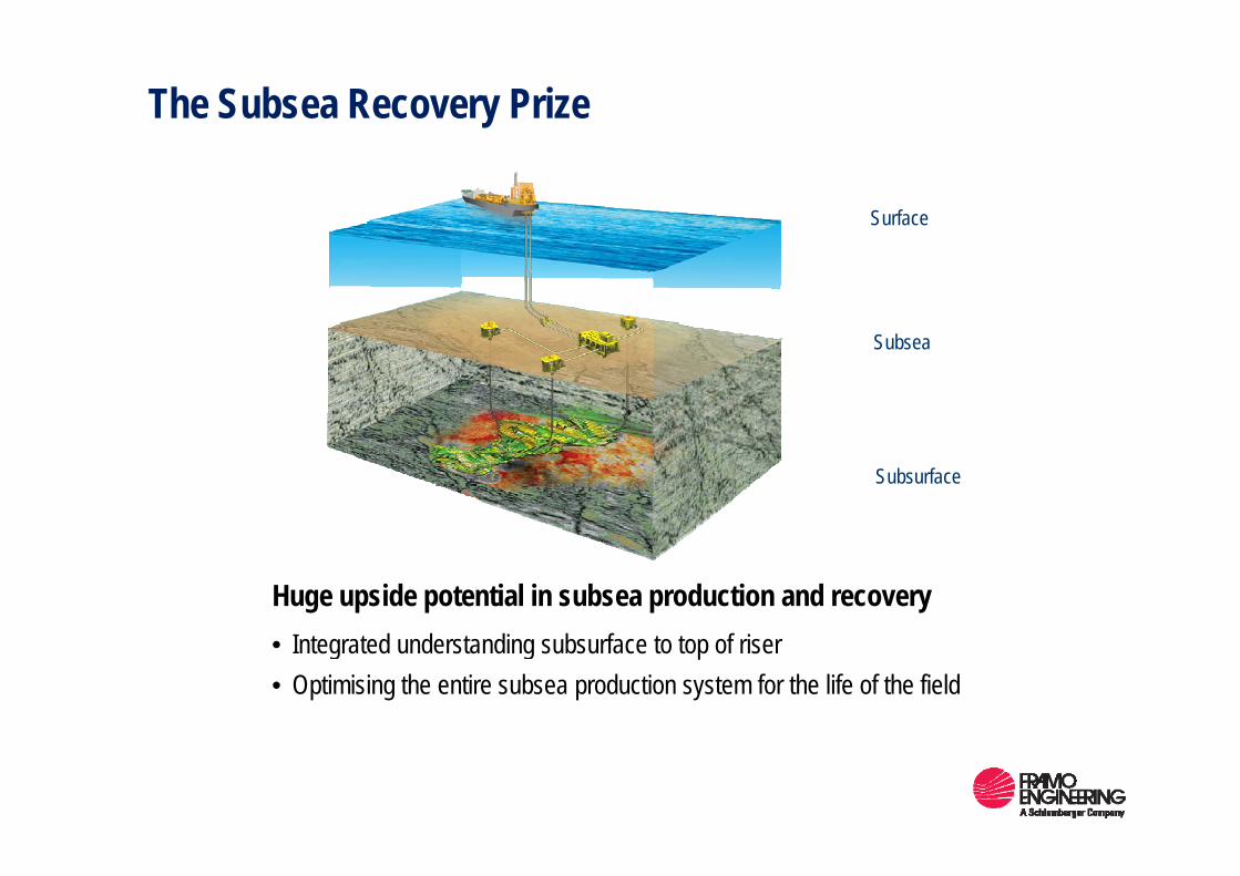
The Subsea Recovery Prize
Surface
SubseaSubsea
Subsurface
Huge upside potential in subsea production and recoveryI t t d d t di b f t t f i• Integrated understanding subsurface to top of riser
• Optimising the entire subsea production system for the life of the field
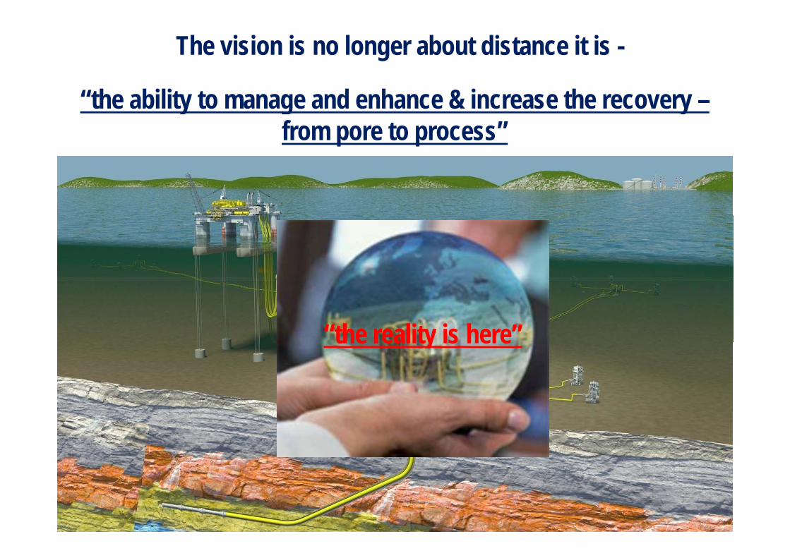
The vision is no longer about distance it is -
“the ability to manage and enhance & increase the recovery –from pore to process”
“the reality is here”the reality is here