enhancing flexibility and transient capability of the diesel engine
TRANSCRIPT
AUTOMOTIVE RESEARCH CENTER
THE UNIVERSITY OF MICHIGAN
arc
Enhancing Flexibility and Enhancing Flexibility and Transient Capability of the Transient Capability of the
Diesel Engine System SimulationDiesel Engine System Simulation
ARC Conference
May 19-20, 1998
Ann Arbor, Michigan
Zoran FilipiDennis Assanis
Dohoy JungGeorge Delagrammatikas
Jennifer LiedtkeDavid Reyes
Doug RosenbaumAlejandro Sales

AUTOMOTIVE RESEARCH CENTER
THE UNIVERSITY OF MICHIGAN
arc
ACKNOWLEDGEMENTSACKNOWLEDGEMENTS
• National Automotive Center (NAC) located within the US Army TARDEC for technical and financial support.
• The University of Wisconsin team has contributed the MATLAB vehicle template and component models for the drivetrain sub-system.
• Guoqing Zhang and Xiaoliu Liu for initial contributions to implementation of the V12 diesel engine simulation in Matlab-SIMULINK.

AUTOMOTIVE RESEARCH CENTER
THE UNIVERSITY OF MICHIGAN
arc
OUTLINEOUTLINE
• Introduction:- The need for enhanced flexibilty and transient capability of
the diesel engine simulation in the context of Powertrain System modeling.
• Thermal network modeling of engine heat rejection.
• Assessment of the potential of the Low Heat Rejection (LHR) tank engine.
• Virtual diesel engine for the HEV.
• Scaling of the complete diesel engine system for optimization studies.
AUTOMOTIVE RESEARCH CENTER
THE UNIVERSITY OF MICHIGAN
arc
FlexibilityFlexibility
• Matlab-SIMULINK environment allows easy reconfiguration of the engine and powertrain system, e.g. variation of the number of cylinders, configuration of the driveline (4x2, 4x4, 6x6 ...).
• Variation of the number of cylinders or cylinder size requires resizing of external diesel engine system components.
• Turbomachinery is modeled using digitized maps, hence for every variation of engine size new set of maps is needed.
• Control devices, such as wastegates also need to be scaled.

AUTOMOTIVE RESEARCH CENTER
THE UNIVERSITY OF MICHIGAN
arc
Need to Enhance Transient CapabilityNeed to Enhance Transient Capability
• Rapid changes of engine speed and load initiate very dramatic thermal transients
• Combustion chamber thermal condition affects volumetric efficiency, heat rejection, combustion and friction in a diesel engine
• Transient heat transfer model needed to enhance simulations ability to predict system response and vehicle performance
• Enhanced heat transfer model essential for evaluation of alternative designs, such as Low Heat Rejection (LHR) engines

AUTOMOTIVE RESEARCH CENTER
THE UNIVERSITY OF MICHIGAN
arcThermal Network Modeling -Thermal Network Modeling -
MOTIVATIONMOTIVATION• Wall temperature variations during engine speed and
load transient
475
480
485
490
495
500
505
510
0 5 10 15 20 25 30
Pis
ton
Sur
face
Te
mp.
(K
)
Time (s)
Cyclicfluctuationsof wall temperatures

AUTOMOTIVE RESEARCH CENTER
THE UNIVERSITY OF MICHIGAN
arc Thermal Behavior of the Thermal Behavior of the LHR EngineLHR Engine
• Cyclic surface temperature variations of conventional metal engines : 5 to 15 K
• Cyclic surface temperature variations of LHR engines: 100 to 150 K (Zirconia Coating)
• Larger temperature swing of LHR engine requires the capability for transient surface temperature prediction.
0
500
1000
1500
2000
0 100 200 300 400 500 600 700
Te
mp
era
ture
(K
)
Crank Angle (deg)
Piston Surface
Mean Gas
Conventional Eng.LHR Eng. (1.0 mm Coating)
----___

AUTOMOTIVE RESEARCH CENTER
THE UNIVERSITY OF MICHIGAN
arc
Modeling IssuesModeling Issues
• Need fidelity and computational efficiency
• Finite Element Methods- High fidelity- Computationally intensive- Need to generate meshes for every new design
• Thermal Network model provides a good compromise:- High fidelity of global component temperature predictions- much less computational effort than FEA methods
AUTOMOTIVE RESEARCH CENTER
THE UNIVERSITY OF MICHIGAN
arc
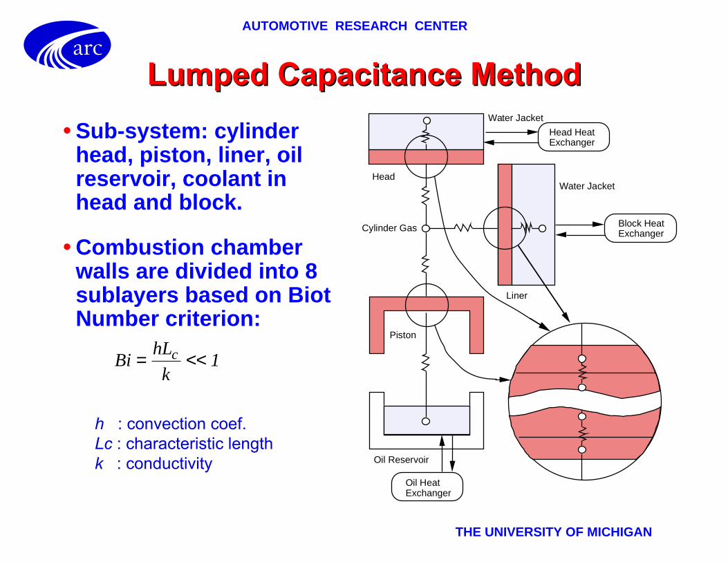
Lumped Capacitance MethodLumped Capacitance Method
• Sub-system: cylinder head, piston, liner, oil reservoir, coolant in head and block.
• Combustion chamber walls are divided into 8 sublayers based on Biot Number criterion:
Liner
Water Jacket
Head
Oil Reservoir
Oil HeatExchanger
Water Jacket
Piston
Head HeatExchanger
Block HeatExchanger
Cylinder Gas
BihL
kc= << 1
h : convection coef.Lc : characteristic lengthk : conductivity

AUTOMOTIVE RESEARCH CENTER
THE UNIVERSITY OF MICHIGAN
arc
LUMPED CAPACITANCE METHODLUMPED CAPACITANCE METHOD(Mathematical Formulation)(Mathematical Formulation)
• Conservation of Energy
T T
RQ Q m c
T T
tjp
ip
i jp
j
condconvrad
sourcepsource
kpk
i v iip
ip−
∑ + ∑ − ∑ =−+
,
..
.
sin
sin
,
1
∆
• Thermal Resistances
RL
kA=
Rr r
Hk= ln( / )2 1
2π
RhAs
= 1
T :Nodal Temp. R : Thermal Resistance Q : Heat Source or Sink m : mass Cv : Const. Vol. Specific Heat i, j : node p, p+1 : Time step ∆t : Time Step Size
(Axial Conduction)
(Radial Conduction)
(Convection)
L : Distance between Nodes k : Conductivity A : Cross Sectional Area r1, r2 : Inner and Outer Radii H : Cylinder Height h : Convection Coef. As : Surface Area
Heat Heat fluxfluxtermterm
CapacitanceCapacitancetermterm

AUTOMOTIVE RESEARCH CENTER
THE UNIVERSITY OF MICHIGAN
arcVirtual Tank EngineVirtual Tank Engine
• Hypothetical V12 Diesel Engine
• 4-Stroke DI Diesel
• 2 Turbochargers
• 2 Intercoolers
• Bore = 6.25 in (15.9 cm)
• Stroke = 6.25 in (15.9 cm)
• CR = 15
• Predicted Power: 1440 HP@2100 rpm
INTER-COOLER
FUELSYSTEM
AirExhaustgas
W.
TC CT
Air Exhaustgas
INTER-COOLER
V12 ENGINE
IM
IM
EM
EM

AUTOMOTIVE RESEARCH CENTER
THE UNIVERSITY OF MICHIGAN
arc
Engine System in SIMULINKEngine System in SIMULINKPowerSim
I/M 1
I/M 2
E/M 1
E/M 2Cylinders
Heat Trans.Model

AUTOMOTIVE RESEARCH CENTER
THE UNIVERSITY OF MICHIGAN
arc
The Effect of Wall Insulation on The Effect of Wall Insulation on System Steady-State andSystem Steady-State and
Transient PerformanceTransient Performance
• Steady-state performance at full load
• Acceleration from stand still with 100% driver’s demand after engine has been warmed up
• Three virtual engine versions:
- Conventional Engine- LHR Engine (0.5 mm Zirconia Coating)- LHR Engine (1.0 mm Zirconia Coating)

AUTOMOTIVE RESEARCH CENTER
THE UNIVERSITY OF MICHIGAN
arc
Engine Performance Comparison - Engine Performance Comparison - Conventional vs. LHR EngineConventional vs. LHR Engine
2000
2500
3000
3500
4000
4500
5000
5500
6000
0
500
1000
1500
2000
800 1000 1200 1400 1600 1800 2000 2200
Conventional Eng.LHR Eng. (0.5 mm Coating)LHR Eng. (1.0 mm Coating)Cummins Eng.
Conventional Eng.LHR Eng. (0.5 mm Coating)LHR Eng. (1.0 mm Coating)Cummins Eng.
To
rqu
e
(Nm
)
Engine Speed (rpm)
Po
we
r (k
W)
AUTOMOTIVE RESEARCH CENTER
THE UNIVERSITY OF MICHIGAN
arc
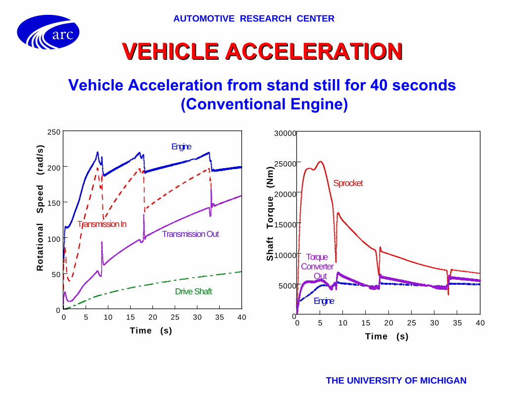
VEHICLE ACCELERATIONVEHICLE ACCELERATION
Vehicle Acceleration from stand still for 40 seconds (Conventional Engine)
0
50
100
150
200
250
0 5 10 15 20 25 30 35 40
Ro
tati
on
al
Sp
ee
d
(ra
d/s
)
Time (s)
Engine
Transmission InTransmission Out
Drive Shaft
0
5000
10000
15000
20000
25000
30000
0 5 10 15 20 25 30 35 40
Sh
aft
T
orq
ue
(N
m)
Time (s)
Engine
Sprocket
TorqueConverter
Out

AUTOMOTIVE RESEARCH CENTER
THE UNIVERSITY OF MICHIGAN
arc
Transient Temperature VariationsTransient Temperature Variations
450
500
550
600
650
700
750
0 5 10 15 20 25 30
Pis
ton
S
urf
ace
T
em
p.
(K)
Time (s)
Conventional Engine
LHR Engine (1.0 mm Coating)
800
810
820
830
840
850
860
870
880
0 5 10 15 20 25 30 35 40
Exh
au
st
Ga
s T
em
pe
ratu
re
(K)
Time (s)
LHR Engine (1.0 mm Coating)
Conventional Engine

AUTOMOTIVE RESEARCH CENTER
THE UNIVERSITY OF MICHIGAN
arc
Boost Pressure Histories -Boost Pressure Histories -Conventional vs. LHRConventional vs. LHR
100
150
200
250
300
350
400
0 5 10 15 20 25 30 35 40
Bo
ost
P
ress
ure
(k
Pa
)
Time (s)
LHR Engine (1.0 mm Coating)
Conventional Engine

AUTOMOTIVE RESEARCH CENTER
THE UNIVERSITY OF MICHIGAN
arc
System Response System Response
0
10
20
30
40
50
60
0 5 10 15 20 25 30 35 40
LHR Engine
Conventional Engine
Ve
hic
le
Sp
ee
d
(Mile
/h)
Time (s)
0.0
0.1
0.2
0.3
0.4
0.5
0.6
0.7
0 5 10 15 20 25 30
Cyl
ind
er
Eq
uiv
ale
nce
R
ati
o
(-)
Time (s)
LHR Engine
Fuel control based on manifold pressure
Comparison of Vehicle Speeds F/A Equivalence Ratio in the LHR Cylinder

AUTOMOTIVE RESEARCH CENTER
THE UNIVERSITY OF MICHIGAN
arc
Enhancing Flexibility for Integration Enhancing Flexibility for Integration with Optimization Codeswith Optimization Codes
• Engine system needs to be simulated within the range, e.g. 1.0 to 1.9 liter displacement.
• External components have to scaled accordingly, including turbomachinery.
• Continuous variation of size required throughout the range

AUTOMOTIVE RESEARCH CENTER
THE UNIVERSITY OF MICHIGAN
arc
1
1.2
1.4
1.6
1.8
2
2.2
2.4
2.6
0 5 10 15
Turbocharged Diesel EngineTurbocharged Diesel Enginefor the HEVfor the HEV
• Baseline engine : VW 1.9 L TDI
• Wide engine speed range requires boost pressure control - wastegate
FUELSYSTEM
4CYL ENGINE
IM
EM
INTER-COOLER
TC
ATMOSPHERE
WGP
ress
ure
Rat
io
Mass flow rate
Simulated engine operating line

AUTOMOTIVE RESEARCH CENTER
THE UNIVERSITY OF MICHIGAN
arc
Scaling of Engine GeometryScaling of Engine Geometry
• Express the following as a function of Bore :- Stroke- Connecting rod length- Valve/port diameters and maximum valve lifts- Manifold volumes
• Assume scaled engine will have same S/B ratio as the baseline engine
• Find new Bore as a function of new displacement. i.e:
• Calculate new engine geometry as a function of B new
BB
S
V
Inewold
old
displ new
cylinders= ( )_ /4 1 3
Π

AUTOMOTIVE RESEARCH CENTER
THE UNIVERSITY OF MICHIGAN
arc
Wastegate ModelingWastegate Modeling
• Wastegate valve dynamics
• m, b, S, A v, Adfgm , Fprel- design parameters
• Pressures at every instant supplied by the engine simulation
m z b z Sz p p A p p A Fexman back v cntrl atm dfgm prel
.. .( ) ( )+ + = − + − −
TURBUNEINLET SIDE
PEXMAN
PBACK
Diaphragm
Pcontrol (boost)
PatmSpring
Needs to be scaled along with engine geometry
A v new/A v old = A dfgmnew/A dfgmold =Vnew/Vold
Spring stiffness and F prel scale linearly with Adfgm new
AUTOMOTIVE RESEARCH CENTER
THE UNIVERSITY OF MICHIGAN
arc
1
1.2
1.4
1.6
1.8
2
2.2
2.4
2.6
0 5 10 15
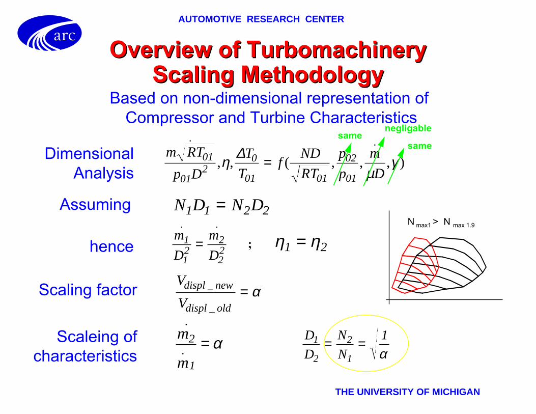
Overview of Turbomachinery Overview of Turbomachinery Scaling MethodologyScaling Methodology
m RT
p D
T
Tf
ND
RT
p
p
m
D01
012
0
01 01
02
01
. .
, , ( , , , )ηµ
γ∆ =
N D N D1 1 2 2=
m
D
m
D1
12
2
22
. .
= η η1 2=
V
Vdispl new
displ old
_
_= α
m
m
2
1
.
. = α D
D
N
N1
2
2
1
1= =α
samenegligable
same
Based on non-dimensional representation of Compressor and Turbine Characteristics
DimensionalAnalysis
Assuming
Scaling factor
hence
Scaleing ofcharacteristics
N max1 > N max 1.9
;

AUTOMOTIVE RESEARCH CENTER
THE UNIVERSITY OF MICHIGAN
arc
Simulated Intake and ExhaustSimulated Intake and ExhaustManifold Pressure for the Range of Manifold Pressure for the Range of
Turbocharged EnginesTurbocharged Engines
1
1 . 2
1 . 4
1 . 6
1 . 8
2
1 0 0 0 2 0 0 0 3 0 0 0 4 0 0 0
Displacement=1.9LDisplacement=1.8LDisplacement=1.7LDisplacement=1.6LDisplacement=1.5LDisplacement=1.4LDisplacement=1.3LDisplacement=1.2LDisplacement=1.1LDisplacement=1.0LIn
take
Man
ifold
Pre
ssur
e (b
ar)
Engine Speed (RPM)
1
1 . 2
1 . 4
1 . 6
1 . 8
2
2 . 2
1 0 0 0 2 0 0 0 3 0 0 0 4 0 0 0
Displacement=1.9LDisplacement=1.8LDisplacement=1.7LDisplacement=1.6LDisplacement=1.5LDisplacement=1.4LDisplacement=1.3LDisplacement=1.2LDisplacement=1.1LDisplacement=1.0L
Exh
aust
Man
ifold
Pre
ssur
e (b
ar)
Engine Speed (RPM)

AUTOMOTIVE RESEARCH CENTER
THE UNIVERSITY OF MICHIGAN
arc
Simulated Power Output and BSFC for Simulated Power Output and BSFC for the Range of Turbocharged Enginesthe Range of Turbocharged Engines
0
1 0
2 0
3 0
4 0
5 0
6 0
1 0 0 0 2 0 0 0 3 0 0 0 4 0 0 0
Displacement=1.9LDisplacement=1.8LDisplacement=1.7LDisplacement=1.6LDisplacement=1.5LDisplacement=1.4LDisplacement=1.3LDisplacement=1.2LDisplacement=1.1LDisplacement=1.0L
Pow
er (
kW)
Engine Speed (RPM)
2 0 0
2 1 0
2 2 0
2 3 0
2 4 0
2 5 0
2 6 0
2 7 0
1 0 0 0 2 0 0 0 3 0 0 0 4 0 0 0
Displacement=1.9LDisplacement=1.8LDisplacement=1.7LDisplacement=1.6LDisplacement=1.5LDisplacement=1.4LDisplacement=1.3LDisplacement=1.2LDisplacement=1.1LDisplacement=1.0L
BS
FC
(g
/kW
-hr)
Engine Speed (RPM)

AUTOMOTIVE RESEARCH CENTER
THE UNIVERSITY OF MICHIGAN
arc
SummarySummary
• Thermal network modeling allows prediction of the effect of the variation of engine component wall temperatures on system response and vehicle performance
• Thermal network model critical for evaluation of the LHR concept for tank propulsion
• Lumped capacitance model provides fidelity at low cost
• Turbomachinery scaling methodology enhances the flexibility of the system simulation and allows continuous variations of engine size in optimization studies.

AUTOMOTIVE RESEARCH CENTER
THE UNIVERSITY OF MICHIGAN
arc
Future ChallengesFuture Challenges
• Extend the thermal network model to include engine external components, e.g. manifolds.
• Investigate engine transients under extreme conditions, i.e.:
- cold start and engine acceleration at very low temperatures- system response at very high ambient temperatures- high altitude operation
• Develop techniques for modeling variable geometry turbines/compressors.
• Investigate the effect of alternative turbocharging techniques, e.g. sequential turbocharging, supercharging + turbocharging etc.