enhancing software portability with a testing and ... · enhancing software portability with a...
TRANSCRIPT

Enhancing Software Portability with a Testing and EvaluationPlatform
Florian Weisshardt, Fraunhofer IPA, [email protected], GermanyJannik Kett, Fraunhofer IPA, [email protected], GermanyThiago de Freitas Oliveira Araujo, Fraunhofer IPA, [email protected], GermanyAlexander Bubeck, Fraunhofer IPA, [email protected], GermanyAlexander Verl, Fraunhofer IPA, [email protected], Germany
Abstract
Recently a variety of service robots is available as standard platforms allowing a worldwide exchange of software forapplications in the service sector or industrial environments. Open source software components enhance this sharingprocess, but require the maintenance of a certain level of quality. This paper presents an approach to a testing andevaluation platform which facilitates the sharing of capabilities over different robot types, environments and applicationcases.
1 IntroductionIn the past years, there have been more and more com-plex and capable service robots available as standard plat-forms [1]. Two examples are the Care-O-bot R© 3 [2] andthe PR2 [3] robots, which are already in use in differ-ent organizations spread all over the world [4]. Firstthese robots were mainly targeted at the research com-munity, but nowadays they get closer to real applicationin the service sector or in industrial environments as well.An example of a robot for industrial environments is therob@work3 platform [5].All these robots share their capabilities due to the useof the open source Robot Operating System (ROS) [6]with the goal to minimize development efforts for a singlerobot by maximizing the reuse of capabilities developedfor each of them. Within the ROS infrastructure it is easyto share software components and developed capabilitiesas shown in [7] like hardware drivers, manipulation, nav-igation and perception components which are organizedin ROS packages.There are more and more industrial robots being avail-able in ROS with the goal to make use of the capabilitiesin the ROS framework. In order to accelerate the transferto the industrial domain the ROS-Industrial Initiative [8]was founded by SwRI.The development in ROS and ROS-Industrial is realizedin a distributed open source community [9] by devel-opers with different background and coding capabilities.Hence, the packages have different activity levels, releasecycles and levels of maturity. From an outside point ofview it is often hard to distinguish well established andwidely used packages from one shot implementations fora single use case.A requirement for sharing functionalities from one robotto another one, from one environment to another one andfrom one to another application, as illustrated in Figure
1, is to make sure that these functionalities will performin a way they are supposed to. The only way to ensurethis wide range of hardware and environment indepen-dent applications is to perform an extensive testing whichis often executed manually and therefore time consumingand related to high costs. One way of decreasing effortand cost is to make use of mostly automated testing ofsoftware capabilities on the target robot, environment andapplication case.
Extensive testing and an objective QA analysis of avail-able ROS components is one of the lessons learned fromthe early stages of the ROS-Industrial Initiative [8]. Theauthors state that it is a major issue to develop reliableindustrial applications.
Figure 1: Sharing functionalities between differentrobots (e.g. Care-O-bot R© 3, PR2 and rob@work3), dif-ferent environments and various application cases.
In this paper, a testing platform for software capabili-ties is proposed which can be tested with a variety ofrobot types, environments and application cases in orderto enhance the transfer of software capabilities. Figure 2shows the hierarchical setup of the proposed testing plat-form which is embedded into the continuous integration

(CI) server Jenkins [10] and offers various types of tests:build, simulation-in-the-loop, hardware-on-the-loop andscenario tests.The paper is structured as follows: After discussing re-lated work and the approach in section 2, the testing plat-form is introduced in section 3. In this section, the setupof the infrastructure and the hierarchical layers of thebuild and test structure are shown. In section 4, the eval-uation of the usage by the Care-O-bot R© Research [11]community is shown. The paper closes with a conclusionand outlook in section 5.
Figure 2: Overview of the testing framework includingbuild, simulation-in-the-loop, hardware-on-the-loop andscenario tests.
2 Related work and approach
The goal of this work is to obtain a stable and portablesoftware which is usable on several robots, in variousenvironments and in different application cases. Neithertype nor architecture nor release version of the installedoperation system should influence the performance or re-liability of the developed code. Moreover, it should beensured that different repository versions are compatibleto each other.In general, software development testing and continu-ous integration are widely used tools. In the domain ofrobotics and ROS there is related work realized by Wil-low Garage and now continued at OSRF [12]. They focuson building ROS code for various architectures and oper-ating systems by executing bare unit tests and buildingbinary releases. They use the Jenkins continuous integra-tion server [10] to automate the process.Based on the work of [12], we propose a testing and eval-uation framework which enables automated testing andprovides feedback about the operational capability andbehavior of software package. Using the proposed testingplatform allows benchmarking tests too. This is not onlyachieved by executing build and unit testing jobs but byadding the capability to execute standardized tests in sim-ulation (simulation-in-the-loop) and on the real hardware(hardware-in-the-loop) as shown in Figure 2. The resultsare visualized by a web-based front end in the form of acomponent catalog which displays the test results includ-ing reports, statistics and videos.The testing platform is based on the following user sto-ries:
Component developer A component developer, re-sponsible for the object perception or the navigation func-tionality, wants to further develop and enhance his code.After committing the changes of the source code, a buildis automatically triggered and tested for several test cases(benchmark tests), on various versions of the operatingsystem, architectures, multiple robots and in a set of en-vironments. Shortly afterwards, the developer receivesa feedback: only 60% of the formerly defined test casesare passed. So there is a need to fix the degradation whichcame into the component. After fixing the code, the de-veloper checks in further changes. The whole testing pro-cess starts again until all tests pass again.
Application developer Furthermore, an applicationdeveloper needs an object perception algorithm for hisapplication. Based on the results of the benchmarkingtests being visualized in the component catalog the appli-cation developer can choose among various available im-plementations for an object perception component. Thisallows to save time while choosing the component whichworks best for the boundary conditions of the specific ap-plication.
3 Testing Platform
Figure 2 shows an overview of the testing platform. First,the code which is organized in software repositories ischecked out on the continuous integration server followedby a build process on different architectures. After a suc-cessful build, there are various test cases which are trig-gered using tests in a simulation environment and fromprevious recorded sensor data. Verifying the correct be-havior of single components a compound of multiplecomponents is tested in a scenario setup. The results ofall stages are recorded and visualized in a web interfaceby the continuous integration server.
The infrastructure and the hierarchical layers of the buildand test structure is shown in Figure 3. Besides com-monly used continuous integration and static code anal-ysis tools the testing framework supports simulation-in-the-loop and hardware-in-the-loop. Before testing insimulation or on the real hardware there is always a socalled priority build which does compilation and basictests on various architectures so that only tests are exe-cuted in simulation or on the hardware if the code at leastcompiles and fulfills some basic requirements. All testscan easily be configured by a specific plugin for Jenkinsand therefore enables various stakeholders of the devel-opment process (component developer, system integratorand application developer) [13] to use the framework.

Figure 3: Hierarchy of the build tests.
Every developer can define its own version of the repos-itory which will be tested by creating a set of jobs onJenkins1. As shown in Figure 3, a set of jobs for onerepository consists of:
Pipe starter jobs The pipe job is responsible for trig-gering a new run of the test pipeline. The test pipelinecan be triggered either manually by the user or by sourcecode changes in a version control system.
Build jobs Build tests cover basic tests by checkout,dependency checks and installation, compiling, staticcode analysis. Each build job is executed in a clean chrootenvironment for various architectures (32bit and 64bit)and OS release version where only the dependencies de-fined in the ROS packages will be installed. This ensuresthe same system configuration for all following jobs. Incase of a successful build the chroot environment will besaved on the Jenkins server as a tarball, so that furtherjobs can execute tests on top of the build job. Results ofthe static code analysis are aggregated on the jobs page.
Hardware-in-the-loop testing Jobs finishing success-fully building software components on the build farm di-rectly trigger a test procedure on the robot platforms thatare integrated into the continuous integration server. Therobots themselves are setup as slaves for Jenkins check-ing out all repositories which are required for testing onthe robot PCs. There are two kind of tests: On the onehand, fully automated tests that require no interactionfrom a human. On the other hand partly manual testswhich need either input from a human observer or needto be supervised by a human because the robot makes useof its actuators and performs movements which could re-sult in damaging the robot or the environment.During the automated testing all hardware componentsare checked. Thus, all sensors, e.g. cameras and laserscanners, can be tested for being available on the robotand delivering correct data using so called hz tests [14].Furthermore, the availability of essential system compo-nents can be verified using diagnostics information [15]about the hardware status. The partly manual tests in-clude moving all actuators, e.g. base, arm and gripper aswell as testing input and output devices, e.g. speakers,
microphones, status LEDs and tactile sensors. The con-trollers of the actuators are tested relating to their abilityto move the components in joint space as well as carte-sian space and deliver status information about their jointconfiguration.The automated and partly manual tests for the hardwarelayer are necessary to ensure the correct behavior of allhardware components before being able to perform anyother high level tests on the robot hardware.
Tests based on previously recorded data Apart fromdirectly testing on the hardware system, the test frame-work provides the possibility to perform tests based onpreviously recorded data, e.g. from real hardware sen-sors.
Listing 1: Configuration file for testing object detec-tion component 2
tolerance: 0.1PKG: object_detection_2mode : default
test_bag:− name: testCase1
bag_path: /test/bagfiles/testCase.bagyaml_path: /test/yaml/testCase.yamltolerance: 0.1 # meters
− name: testCase2bag_path: /test/bagfiles/testCase2.bagyaml_path: /test/yaml/testCase2.yamltolerance: 0.2 # meters
Listings 1 shows the definition of tests for an object de-tection component where the ground truth data is givenby another configuration file shown in listing 2. It con-tains the definition of objects type and position.
Listing 2: Configuration file defining ground truthdata for object detection testing
objects:− label: milk
tolerance: 0.04 # metersposition : [−0.09, −0.35, 1.34] # [x,y,z]orientation : [0 , 0, 0] # [r,p,y]
− label: zwiebacktolerance: 0.05 # metersposition : [−0.09, −0.35, 1.33] # [x,y,z]orientation : [0 , 0, 0] # [r,p,y]
Simulation-in-the-loop testing Testing in a simulationenvironment offer the opportunity to setup a multitude oftest cases without the need of avoiding damages to therobot and the environment because simulation can eas-ily restart, e.g. in case of collision. This allows fullyautomated tests without supervision by an operator. Forthe simulation tests the Jenkins system will automaticallystart the jobs on a simulation enabled host and run thesimulation prior to executing the test itself.
1A running version of the test infrastructure can be found on http://build.care-o-bot.org
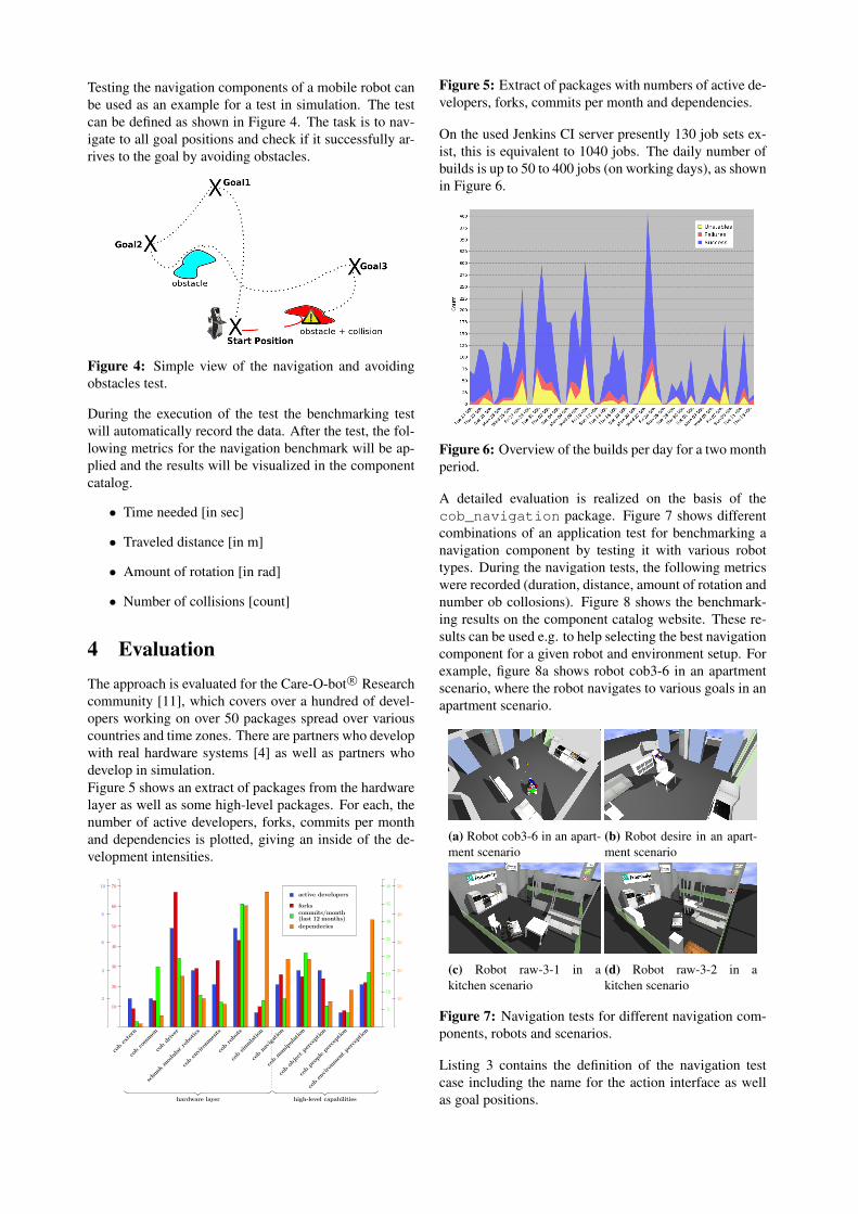
Testing the navigation components of a mobile robot canbe used as an example for a test in simulation. The testcan be defined as shown in Figure 4. The task is to nav-igate to all goal positions and check if it successfully ar-rives to the goal by avoiding obstacles.
Figure 4: Simple view of the navigation and avoidingobstacles test.
During the execution of the test the benchmarking testwill automatically record the data. After the test, the fol-lowing metrics for the navigation benchmark will be ap-plied and the results will be visualized in the componentcatalog.
• Time needed [in sec]
• Traveled distance [in m]
• Amount of rotation [in rad]
• Number of collisions [count]
4 EvaluationThe approach is evaluated for the Care-O-bot R© Researchcommunity [11], which covers over a hundred of devel-opers working on over 50 packages spread over variouscountries and time zones. There are partners who developwith real hardware systems [4] as well as partners whodevelop in simulation.Figure 5 shows an extract of packages from the hardwarelayer as well as some high-level packages. For each, thenumber of active developers, forks, commits per monthand dependencies is plotted, giving an inside of the de-velopment intensities.
cobextern
cobcommon
cobdriver
schunk
modularrobotics
cobenvironm
ents
cobrobots
cobsimulation
cobnavigation
cobmanipulation
cobobjectperception
cobpeopleperception
cobenvironm
entperception
2
4
6
8
10
10
20
30
40
50
60
70
5
10
15
20
25
30
35
40
10
20
30
40
50
active developers
forkscommits/month(last 12 months)
dependecies
hardware layer high-level capabilities
Figure 5: Extract of packages with numbers of active de-velopers, forks, commits per month and dependencies.
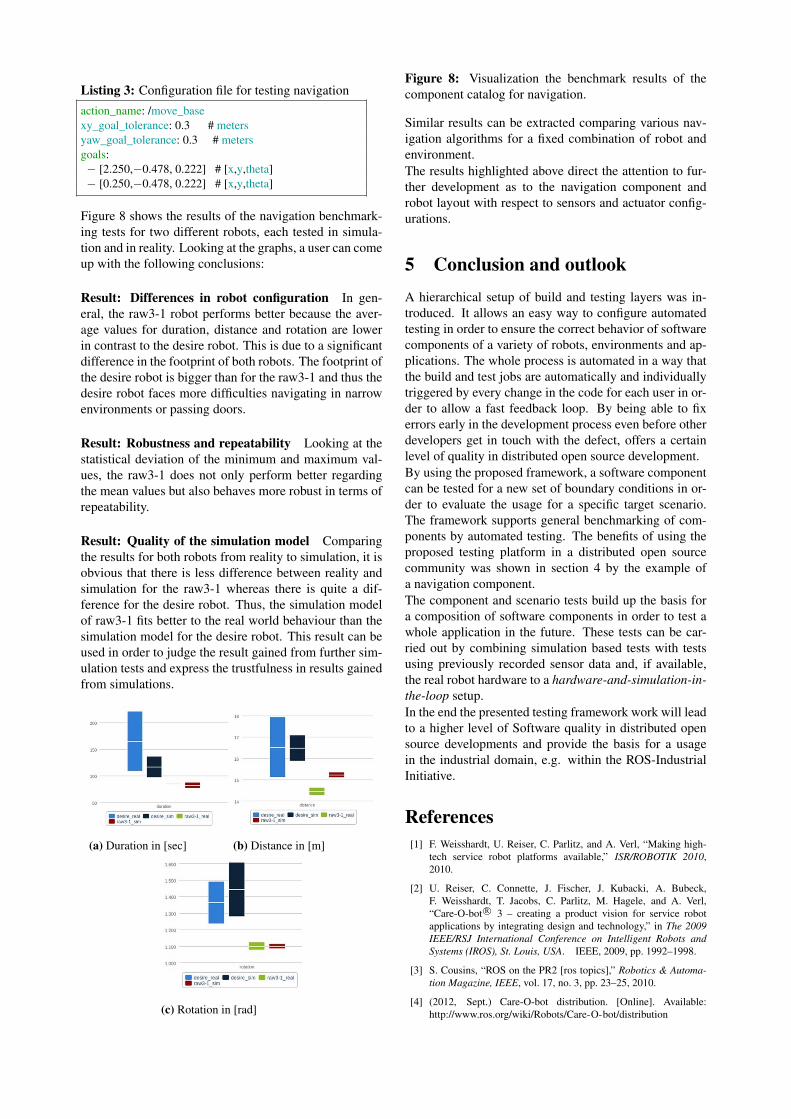
On the used Jenkins CI server presently 130 job sets ex-ist, this is equivalent to 1040 jobs. The daily number ofbuilds is up to 50 to 400 jobs (on working days), as shownin Figure 6.
Figure 6: Overview of the builds per day for a two monthperiod.
A detailed evaluation is realized on the basis of thecob_navigation package. Figure 7 shows differentcombinations of an application test for benchmarking anavigation component by testing it with various robottypes. During the navigation tests, the following metricswere recorded (duration, distance, amount of rotation andnumber ob collosions). Figure 8 shows the benchmark-ing results on the component catalog website. These re-sults can be used e.g. to help selecting the best navigationcomponent for a given robot and environment setup. Forexample, figure 8a shows robot cob3-6 in an apartmentscenario, where the robot navigates to various goals in anapartment scenario.
(a) Robot cob3-6 in an apart-ment scenario
(b) Robot desire in an apart-ment scenario
(c) Robot raw-3-1 in akitchen scenario
(d) Robot raw-3-2 in akitchen scenario
Figure 7: Navigation tests for different navigation com-ponents, robots and scenarios.
Listing 3 contains the definition of the navigation testcase including the name for the action interface as wellas goal positions.
Listing 3: Configuration file for testing navigation
action_name: /move_basexy_goal_tolerance: 0.3 # metersyaw_goal_tolerance: 0.3 # metersgoals:− [2.250,−0.478, 0.222] # [x,y,theta]− [0.250,−0.478, 0.222] # [x,y,theta]
Figure 8 shows the results of the navigation benchmark-ing tests for two different robots, each tested in simula-tion and in reality. Looking at the graphs, a user can comeup with the following conclusions:
Result: Differences in robot configuration In gen-eral, the raw3-1 robot performs better because the aver-age values for duration, distance and rotation are lowerin contrast to the desire robot. This is due to a significantdifference in the footprint of both robots. The footprint ofthe desire robot is bigger than for the raw3-1 and thus thedesire robot faces more difficulties navigating in narrowenvironments or passing doors.
Result: Robustness and repeatability Looking at thestatistical deviation of the minimum and maximum val-ues, the raw3-1 does not only perform better regardingthe mean values but also behaves more robust in terms ofrepeatability.
Result: Quality of the simulation model Comparingthe results for both robots from reality to simulation, it isobvious that there is less difference between reality andsimulation for the raw3-1 whereas there is quite a dif-ference for the desire robot. Thus, the simulation modelof raw3-1 fits better to the real world behaviour than thesimulation model for the desire robot. This result can beused in order to judge the result gained from further sim-ulation tests and express the trustfulness in results gainedfrom simulations.
(a) Duration in [sec] (b) Distance in [m]
(c) Rotation in [rad]
Figure 8: Visualization the benchmark results of thecomponent catalog for navigation.
Similar results can be extracted comparing various nav-igation algorithms for a fixed combination of robot andenvironment.The results highlighted above direct the attention to fur-ther development as to the navigation component androbot layout with respect to sensors and actuator config-urations.
5 Conclusion and outlookA hierarchical setup of build and testing layers was in-troduced. It allows an easy way to configure automatedtesting in order to ensure the correct behavior of softwarecomponents of a variety of robots, environments and ap-plications. The whole process is automated in a way thatthe build and test jobs are automatically and individuallytriggered by every change in the code for each user in or-der to allow a fast feedback loop. By being able to fixerrors early in the development process even before otherdevelopers get in touch with the defect, offers a certainlevel of quality in distributed open source development.By using the proposed framework, a software componentcan be tested for a new set of boundary conditions in or-der to evaluate the usage for a specific target scenario.The framework supports general benchmarking of com-ponents by automated testing. The benefits of using theproposed testing platform in a distributed open sourcecommunity was shown in section 4 by the example ofa navigation component.The component and scenario tests build up the basis fora composition of software components in order to test awhole application in the future. These tests can be car-ried out by combining simulation based tests with testsusing previously recorded sensor data and, if available,the real robot hardware to a hardware-and-simulation-in-the-loop setup.In the end the presented testing framework work will leadto a higher level of Software quality in distributed opensource developments and provide the basis for a usagein the industrial domain, e.g. within the ROS-IndustrialInitiative.
References[1] F. Weisshardt, U. Reiser, C. Parlitz, and A. Verl, “Making high-
tech service robot platforms available,” ISR/ROBOTIK 2010,2010.
[2] U. Reiser, C. Connette, J. Fischer, J. Kubacki, A. Bubeck,F. Weisshardt, T. Jacobs, C. Parlitz, M. Hagele, and A. Verl,“Care-O-bot R© 3 – creating a product vision for service robotapplications by integrating design and technology,” in The 2009IEEE/RSJ International Conference on Intelligent Robots andSystems (IROS), St. Louis, USA. IEEE, 2009, pp. 1992–1998.
[3] S. Cousins, “ROS on the PR2 [ros topics],” Robotics & Automa-tion Magazine, IEEE, vol. 17, no. 3, pp. 23–25, 2010.
[4] (2012, Sept.) Care-O-bot distribution. [Online]. Available:http://www.ros.org/wiki/Robots/Care-O-bot/distribution

[5] (2012, Sept.) Rob@work 3. [Online]. Available: http://www.care-o-bot-research.org/robatwork-3
[6] M. Quigley, K. Conley, B. Gerkey, J. Faust, T. Foote, J. Leibs,R. Wheeler, and A. Ng, “ROS: an open-source robot operatingsystem,” in ICRA Workshop on Open Source Software, vol. 3, no.3.2, 2009.
[7] S. Cousins, B. Gerkey, K. Conley, and W. Garage, “Sharing soft-ware with ROS [ros topics],” Robotics & Automation Magazine,IEEE, vol. 17, no. 2, pp. 12–14, 2010.
[8] S. Edwards and C. Lewis, “Ros-industrial: applying the robot op-erating system (ros) to industrial applications,” in IEEE Int. Con-ference on Robotics and Automation, ECHORD Workshop, 2012.
[9] (2013, Nov.) ROS metrics. [Online]. Available: http://wiki.ros.org/Metrics
[10] (2013, Nov.) Jenkins CI. [Online]. Available: http://jenkins-ci.org/
[11] (2012, Sept.) Care-O-bot Research. [Online]. Available:http://www.care-o-bot-research.org
[12] (2013, Nov.) Continuous integration at OSRF. [Online]. Avail-able: http://jenkins.ros.org/
[13] A. Bubeck, F. Weisshardt, T. Sing, U. Reiser, M. Hagele, andA. Verl, “Implementing best practices for systems integration anddistributed software development in service robotics-the care-o-bot R© robot family,” in System Integration (SII), 2012 IEEE/SICEInternational Symposium on. IEEE, 2012, pp. 609–614.
[14] (2012, Sept.) ROS hz tests. [Online]. Available: http://www.ros.org/wiki/rostest/Nodes
[15] (2012, Sept.) ROS diagnostics. [Online]. Available: http://www.ros.org/wiki/diagnostics
Acknowledgments
The work leading to these results has received fund-ing from the European Community’s Seventh Frame-work Program (FP7/2007-2013) under grant agreementno 609206.