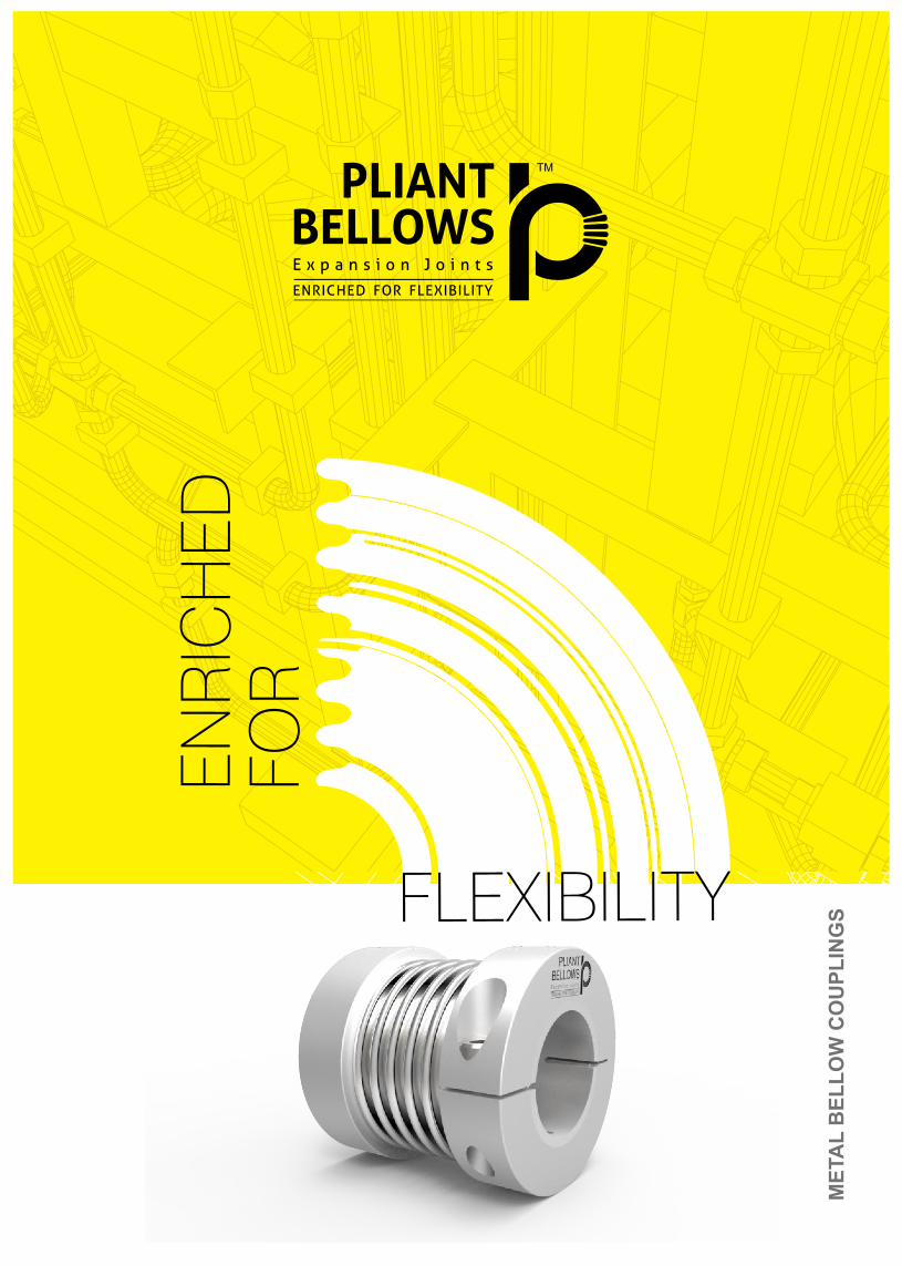
enriched for flexibility - bellows · pliant bellows is the brand name of bellows manufactured by...
TRANSCRIPT
ME
TA
L B
EL
LO
W C
OU
PL
ING
S
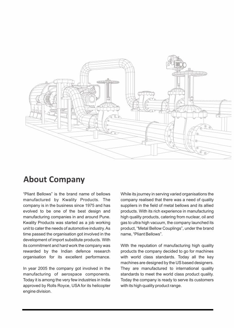
“Pliant Bellows” is the brand name of bellows
manufactured by Kwality Products. The
company is in the business since 1975 and has
evolved to be one of the best design and
manufacturing companies in and around Pune.
Kwality Products was started as a job working
unit to cater the needs of automotive industry. As
time passed the organisation got involved in the
development of import substitute products. With
its commitment and hard work the company was
rewarded by the Indian defence research
organisation for its excellent performance.
In year 2005 the company got involved in the
manufacturing of aerospace components.
Today it is among the very few industries in India
approved by Rolls Royce, USA for its helicopter
engine division.
While its journey in serving varied organisations the
company realised that there was a need of quality
suppliers in the field of metal bellows and its allied
products. With its rich experience in manufacturing
high quality products, catering from nuclear, oil and
gas to ultra high vacuum, the company launched its
product, “Metal Bellow Couplings”, under the brand
name, “Pliant Bellows”.
With the reputation of manufacturing high quality
products the company decided to go for machines
with world class standards. Today all the key
machines are designed by the US based designers.
They are manufactured to international quality
standards to meet the world class product quality.
Today the company is ready to serve its customers
with its high quality product range.
About Company

Business Philosophy & Strengths
- As the CEO and GM are technically qualifi ed, the general orientation of the company is towards technical excellence .The work culture has also been developed accordingly.
- The company implements, Kaizen (Continuous Improvement) and 5 S techniques to keep the entire
system up to mark.
- To facilitate the above at operational level, experienced and qualifi ed manpower has been employed.
- The company has endeavoured to meet and achieve the quality standards set by the customers.
Systems And Certifi cations
Kwality Products is an ISO 9001:2015 cert ied company and is well supported by ERP Software to maintain the documentation and the entire tracking from incoming raw material to dispatch. The company has been approved by Rolls Royce for its engineering needs.

Mr. Anand Uttarkar CEO
The CEO, Mr. Anand Uttarkar is a qualifi ed engineer
with a M.S. Degree in Industrial Engineering from Texas,
USA and has rich experience in the current line of
activity.
Mrs. Priya Bagul-UttarkarGeneral Manager
The GM, Mrs. Priya Bagul-Uttarkar is a Mechanical
Engineer with a post graduation diploma in Tool & Die
designing from Indo-German Tool Room and MBA in
Finance from a reputed Institute in India.
Leadership Team
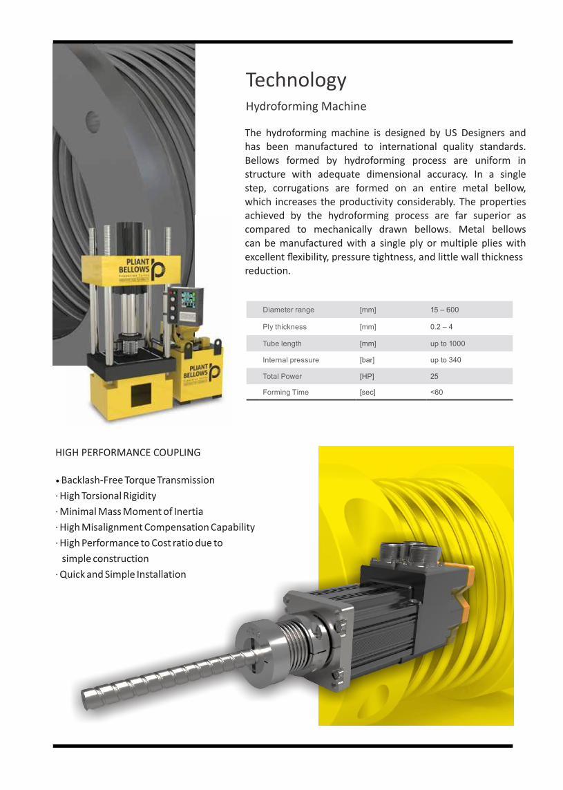
The hydroforming machine is designed by US Designers and has been manufactured to international quality standards. Bellows formed by hydroforming process are uniform in structure with adequate dimensional accuracy. In a single step, corrugations are formed on an entire metal bellow, which increases the productivity considerably. The properties achieved by the hydroforming process are far superior as compared to mechanically drawn bellows. Metal bellows can be manufactured with a single ply or multiple plies with excellent fl exibility, pressure tightness, and little wall thickness reduction.
Diameter range [mm] 15 – 600
Ply thickness [mm] 0.2 – 4
Tube length [mm] up to 1000
Internal pressure [bar] up to 340
Total Power [HP] 25
Forming Time [sec] <60
HIGH PERFORMANCE COUPLING
Backlash-Free Torque Transmission
· High Torsional Rigidity
· Minimal Mass Moment of Inertia
· High Misalignment Compensation Capability
· High Performance to Cost ratio due to
simple construction
· Quick and Simple Installation
TechnologyHydroforming Machine
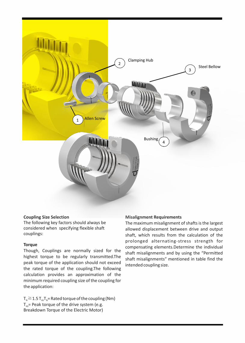
Misalignment RequirementsThe maximum misalignment of shafts is the largest allowed displacement between drive and output shaft, which results from the calculation of the prolonged alternating-stress strength for compensating elements.Determine the individual shaft misalignments and by using the “Permitted shaft misalignments“ mentioned in table find the intended coupling size.
Coupling Size SelectionThe following key factors should always be considered when specifying flexible shaft couplings:
TorqueThough, Couplings are normally sized for the highest torque to be regularly transmitted.The peak torque of the application should not exceed the rated torque of the coupling.The following calculation provides an approximation of the minimum required coupling size of the coupling for the application:
T �1.5 T T = Rated torque of the coupling (Nm)N AS N
T = Peak torque of the drive system (e.g. AS
Breakdown Torque of the Electric Motor)
Clamping Hub
Steel Bellow
Bushing
Allen Screw
2
3
4
1
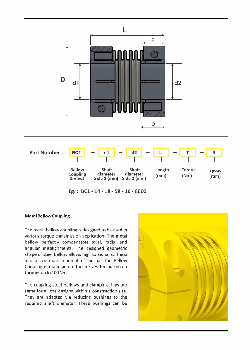
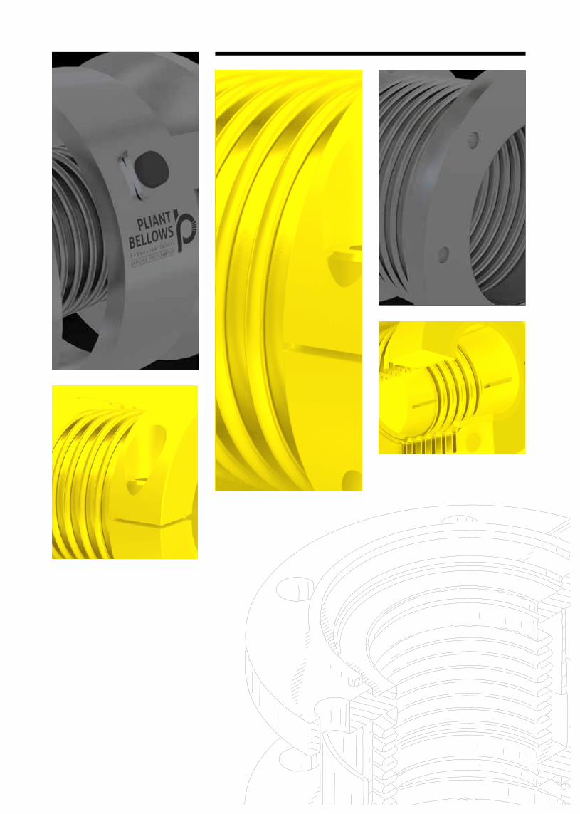
Metal Bellow Coupling
The metal bellow coupling is designed to be used in various torque transmission application. The metal bellow perfectly compensates axial, radial and angular misalignments. The designed geometric shape of steel bellow allows high torsional stiffness and a low mass moment of inertia. The Bellow Coupling is manufactured in 5 sizes for maximum torques up to 400 Nm.
The coupling steel bellows and clamping rings are same for all the designs within a construction size. They are adapted via reducing bushings to the required shaft diameter. These bushings can be
Part Number :
Bellow CouplingSeries1
Shaft diameter
Side 1 (mm)
Shaft diameter
Side 2 (mm)
Length (mm)
Torque (Nm)
Speed (rpm)
BC1 d1 d2 L T S
Eg. : BC1 ‐ 14 ‐ 18 ‐ 58 ‐ 10 ‐ 8000
L
c
b
d2D
d1
Rated Torque Test Torque Rated Torque Test Torque Rated Torque Test Torque Rated Torque Test Torque Rated Torque Test Torque
(mm) Nm Nm Nm Nm Nm Nm Nm Nm Nm Nm
8 9 14 - - - - - - - -
9 11 17 - - - - - - - -
10 13 20 20 32 - - - - - -
11 14 21 24 36 - - - - - -
12 16 24 26 39 - - - - - -
14 16 24 31 47 35 51 - - - -
15 16 24 33 50 42 63 - - - -
16 16 24 35 52 51 77 - - - -
18 16 24 39 59 58 87 - - - -
19 16 24 40 60 61 91 - - - -
20 16 24 40 60 67 100 133 199 - -
24 - - 40 60 74 110 147 220 - -
25 - - 40 60 85 128 167 250 205 301
28 - - 40 60 85 128 187 280 225 323
30 - - 40 60 85 128 200 300 240 360
32 - - - - 85 128 200 300 256 384
35 - - - - 85 128 200 300 280 420
38 - - - - 85 128 200 300 305 457
40 - - - - 85 128 200 300 320 480
42 - - - - 85 128 200 300 340 510
45 - - - - - - 200 300 360 540
50 - - - - - - 200 300 400 600
55 - - - - - - 200 300 400 600
60 - - - - - - - - 400 600
65 - - - - - - - - 400 600
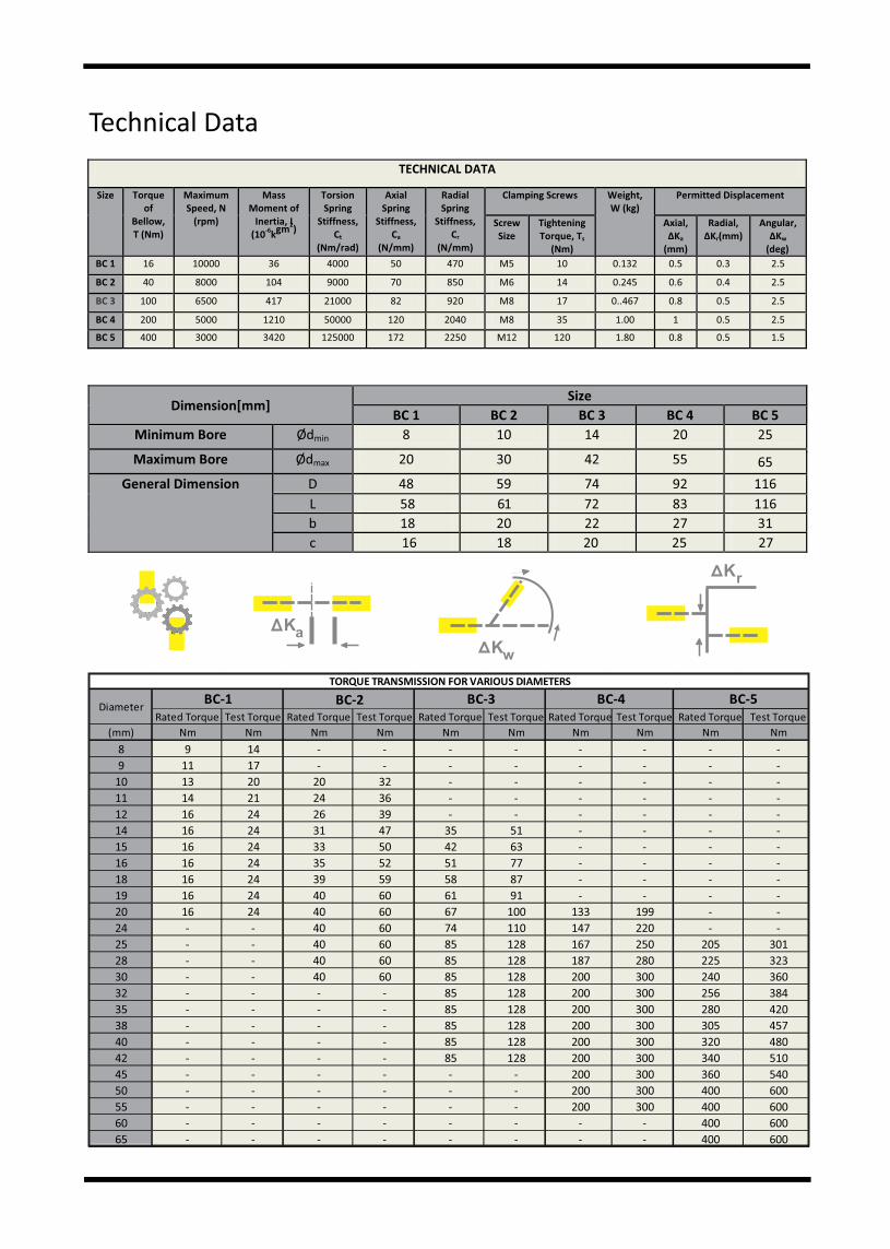
TORQUE TRANSMISSION FOR VARIOUS DIAMETERS
BC‐1 BC‐2 BC‐3 BC‐4 BC‐5Diameter
Technical Data
TECHNICAL DATA
Size
Torque of
Bellow, T (Nm)
Maximum Speed, N
(rpm)
Mass Moment of
Inertia, I
(102
‐6 gm ) k
Torsion Spring
Stiffness, Ct
(Nm/rad)
Axial Spring
Stiffness, Ca
(N/mm)
Radial Spring
Stiffness, C r
(N/mm)
Clamping Screws
Weight, W (kg)
Permitted Displacement
Screw Size
Tightening Torque, Ts
(Nm)
Axial, ∆Ka
(mm)
Radial,
∆Kr(mm) Angular,
∆Kw
(deg)
BC 1
16
10000
36
4000
50
470
M5
10
0.132
0.5
0.3
2.5
BC 2 40 8000 104 9000 70 850 M6 14 0.245 0.6 0.4 2.5
BC 3 100 6500 417 21000 82 920 M8 17 0..467 0.8 0.5 2.5
BC 4 200 5000 1210 50000 120 2040 M8 35 1.00 1 0.5 2.5
BC 5 400 3000 3420 125000 172 2250 M12 120 1.80 0.8 0.5 1.5
Dimension[mm] Size
BC 1 BC 2 BC 3 BC 4 BC 5 Minimum Bore
Ødmin
8
10
14
20
25
Maximum Bore
Ødmax
20
30
42
55
65
General Dimension
D
48
59
74
92
116 L
58
61
72
83
116
b
18
20
22
27
31 c 16 18 20 25 27
KaKw
Kr

Installing Couplings
General Instructions-
1. Ensure that both the shafts are free of burrs, damage, or foreign matter, and can penetrate the bores. 2. Install the coupling by holding the shaft and the related hub, rotating it back and forth as you progress
it along the shaft. 3. Do not apply any forces that cause extension, compression or lateral displacement of the coupling
beyond its permissible offsets.
Installation Guidelines‐1. Position and secure the larger of the 2 shafts (if different) and progress the coupling onto it.
2. Progress the second shaft into the bore, taking care not to lever either shaft against the inner wall of the spacer.
3. Progress the coupling along the shafts to a position midway between the shaft terminations. Rotate the coupling to ensure it is not binding and is in its natural state, i.e., neither extended nor compressed.
4. Align the second shaft with the first using a straight edge and feeler gauges or a dial indicator.
5. Secure the second shaft and re-check alignment. Final alignment must be within the permissible offsets.
6. Secure one hub, tightening each screw alternately. Repeat for the second hub.
- Power GenerationApplications
- Sugar Mill
- Infrastructure
- HVAC
- Cryogenic
- Steel Industries
- Measurement & Control Systems
- Pulp & Paper
- Oil & Gas
- Engine Exhaust
- Solar Technology
- Chemical Industries
- Instrument & Valve Industries
- Water/ Waste Water
- Nuclear Plant
- Automobile Industries
Testing - Hydrostatic Pressure and Leak Test
Capabilities - Pneumatic Bubble Soap Leak Test
- Vacuum Test
- Dye Penetrant Test
- Visual Test
- Fatigue Test
- Squirm Test
- Spring Rate Test
- Radiography Test
- X-Ray Test
- Ultrasonic Test
- Helium Leak Detection Test
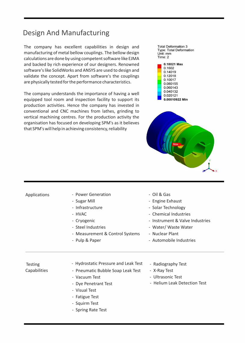
Design And Manufacturing
The company has excellent capabilities in design and manufacturing of metal bellow couplings. The bellow design calculations are done by using competent software like EJMA and backed by rich experience of our designers. Renowned software's like SolidWorks and ANSYS are used to design and validate the concept. Apart from software's the couplings are physically tested for the performance characteristics.
The company understands the importance of having a well equipped tool room and inspection facility to support its production activities. Hence the company has invested in conventional and CNC machines from lathes, grinding to vertical machining centres. For the production activity the organisation has focused on developing SPM's as it believes that SPM's will help in achieving consistency, reliability

Other Products
Axial Expansion Joints
These Joints are the simplest form of bellows manufactured. Pliant Bellows can manufacture
them in single and multiple ply.
Lateral Expansion Joints
Lateral expansion joints refers to the direction perpendicular to the centre line of the pipe expansion joint. Lateral defl ection is also called as Parallel Offset and Transverse. The lateral expansion joints are also known as tied lateral expansion joints.
Hinged Expansion Joints
When the angular movement is only in one plane, hinge or angular expansion joints are used. An angular expansion can be expressed when an expansion joint experience bending about its centre which is the centre line and half way between the ends of metal bellows.
Pressure Switch Bellows
Pressure switches are designed to make electrical contact when a set pressure is reached. These switches can be designed to close or open, based on the pressure rising or falling.
Universal Expansion Joints
Universal expansion joints are made up of 2 elements of bellows joined together by a common spool piece so it is also called as Double Bellows Expansion Joint or Universal Bellows.
Inline Pressure Balanced Expansion Joints
An inline pressure balanced expansion jointaccommodates axial and lateral movementsand counteracts the bellows pressure thrust.
Pressure Balanced (Elbow) Expansion Joints
An Elbow Pressure Balanced Expansion Joint is designed to absorb externally imposed axial movement without imposing pressure loading on the system.
Gimbal Expansion Joints
The gimbal expansion joints are the most reliable expansion joint since it is capable of absorbing angular motion in all the

Website: www.pliantbellows.com|Tele: +91‐7028997949 / +91‐20‐26814175
Customer: ...................................................................Sr.No: ............... Date: ...............
Email Id: ...................................................Mob. No.: .......................PO No: ……........……
Type of Bellow Coupling
Bellow Material
Bore Diameter
Length (L)
Torque (T)
Speed (S)
Part Number
BC1……..........................BC2: ……......................BC3: .....................
BC4: …………...................BC5: ….…...................
Material: …................……………………………….No of Ply: .……………….
Ply Thickness: …………………………
d1(mm):.................................. d2(mm)...............................
In mm: ……………………………...................
In Nm :……………….………....
In rpm :……………….………....
BC Sr.No- dmin- dmax- Length- Torque- Speed
Part Number Generation:
Part Number :
Bellow CouplingSeries1
Shaft diameter
Side 1 (mm)
Shaft diameter
Side 2 (mm)
Length (mm)
Torque (Nm)
Speed (rpm)
BC1 d1 d2 L T S
Email Id: [email protected]
Eg. : BC1 ‐ 14 ‐ 18 ‐ 58 ‐ 10 ‐ 8000
ENRICHED��FOR��FLEXIBILITY
PLIANT BELLOWS DATASHEET

KWALITY PRODUCTS
ISO 9001:2015
©Copyright registered. All rights reserved. Imitation of this brochure is a cognisable offence.
Corporate Office
Final Plot No.38/1, Ramtekdi
Industrial Estate, Hadapsar, Pune,
Maharashtra, India- 411013
Phone
+91-20-2681 4175
+91-70289 97949
+91-98904 54224
Website: www.pliantbellows.com
ww
w.p
epd
eck.
com