envi programmer’s guide - harris geospatial solutions · the envi programmer’s guide provides...
TRANSCRIPT

ENVI Programmer’s Guide
ENVI Version 4.7August, 2009 EditionCopyright © ITT VIsual Information SolutionsAll Rights Reserved
20PRG47DOC

Restricted Rights NoticeThe IDL®, IDL Advanced Math and Stats™, ENVI®, ENVI Zoom™, and ENVI® EX software programs and the accompanying procedures, functions, and documentation described herein are sold under license agreement. Their use, duplication, and disclosure are subject to the restrictions stated in the license agreement. ITT Visual Information Solutions reserves the right to make changes to this document at any time and without notice.
Limitation of WarrantyITT Visual Information Solutions makes no warranties, either express or implied, as to any matter not expressly set forth in the license agreement, including without limitation the condition of the software, merchantability, or fitness for any particular purpose.ITT Visual Information Solutions shall not be liable for any direct, consequential, or other damages suffered by the Licensee or any others resulting from use of the software packages or their documentation.
Permission to Reproduce this ManualIf you are a licensed user of these products, ITT Visual Information Solutions grants you a limited, nontransferable license to reproduce this particular document provided such copies are for your use only and are not sold or distributed to third parties. All such copies must contain the title page and this notice page in their entirety.
Export Control InformationThis software and associated documentation are subject to U.S. export controls including the United States Export Administration Regulations. The recipient is responsible for ensuring compliance with all applicable U.S. export control laws and regulations. These laws include restrictions on destinations, end users, and end use.
AcknowledgmentsENVI® and IDL® are registered trademarks of ITT Corporation, registered in the United States Patent and Trademark Office. ION™, ION Script™, ION Java™, and ENVI Zoom™ are trademarks of ITT Visual Information Solutions.ESRI®, ArcGIS®, ArcView®, and ArcInfo® are registered trademarks of ESRI.Portions of this work are Copyright © 2009 ESRI. All rights reserved.PowerPoint® and Windows® are registered trademarks of Microsoft Corporation in the United States and/or other countries.Macintosh® is a registered trademark of is a trademark of Apple Inc., registered in the U.S. and other countries.UNIX® is a registered trademark of The Open Group.Adobe Illustrator® and Adobe PDF® Print Engine are either registered trademarks or trademarks of Adobe Systems Incorporated in the United States and/or other countries.Numerical Recipes™ is a trademark of Numerical Recipes Software. Numerical Recipes routines are used by permission.GRG2™ is a trademark of Windward Technologies, Inc. The GRG2 software for nonlinear optimization is used by permission.NCSA Hierarchical Data Format (HDF) Software Library and Utilities. Copyright © 1988-2001, The Board of Trustees of the University of Illinois. All rights reserved.NCSA HDF5 (Hierarchical Data Format 5) Software Library and Utilities. Copyright © 1998-2002, by the Board of Trustees of the University of Illinois. All rights reserved.CDF Library. Copyright © 2002, National Space Science Data Center, NASA/Goddard Space Flight Center.NetCDF Library. Copyright © 1993-1999, University Corporation for Atmospheric Research/Unidata.HDF EOS Library. Copyright © 1996, Hughes and Applied Research Corporation.SMACC. Copyright © 2000-2004, Spectral Sciences, Inc. and ITT Visual Information Solutions. All rights reserved.This software is based in part on the work of the Independent JPEG Group.Portions of this software are copyrighted by DataDirect Technologies, © 1991-2003.BandMax®. Copyright © 2003, The Galileo Group Inc.Portions of this computer program are copyright © 1995-2008 Celartem, Inc., doing business as LizardTech. All rights reserved. MrSID is protected by U.S. Patent No. 5,710,835. Foreign Patents Pending.Portions of this software were developed using Unisearch’s Kakadu software, for which ITT has a commercial license. Kakadu Software. Copyright © 2001. The University of New South Wales, UNSW, Sydney NSW 2052, Australia, and Unisearch Ltd, Australia.This product includes software developed by the Apache Software Foundation (www.apache.org/).MODTRAN is licensed from the United States of America under U.S. Patent No. 5,315,513 and U.S. Patent No. 5,884,226.QUAC and FLAASH are licensed from Spectral Sciences, Inc. under U.S. Patent No. 6,909,815 and U.S. Patent No. 7,046,859 B2.Portions of this software are copyrighted by Merge Technologies Incorporated.Support Vector Machine (SVM) is based on the LIBSVM library written by Chih-Chung Chang and Chih-Jen Lin (www.csie.ntu.edu.tw/~cjlin/libsvm), adapted by ITT Visual Information Solutions for remote sensing image supervised classification purposes.IDL Wavelet Toolkit Copyright © 2002, Christopher Torrence.IMSL is a trademark of Visual Numerics, Inc. Copyright © 1970-2006 by Visual Numerics, Inc. All Rights Reserved.Other trademarks and registered trademarks are the property of the respective trademark holders.

Contents
Overview of ENVI Programming ...................................................................... 9About This Guide ......................................................................................................................... 10Extending ENVI ........................................................................................................................... 11Band and Spectral Math User Functions ................................................................................ 11Batch Mode ............................................................................................................................ 11User Functions ....................................................................................................................... 11ENVI Menu Files ................................................................................................................... 12Interactive User Routines ....................................................................................................... 12Compiling ............................................................................................................................... 12Custom File Input ................................................................................................................... 12Toggle Catch .......................................................................................................................... 13
Introduction to ENVI Programming ............................................................................................. 14Library Routines .................................................................................................................... 14ENVI Save Files ..................................................................................................................... 14Differences in File I/O Between ENVI and IDL ................................................................... 15The ENVI and IDL Library Directories ................................................................................. 15Common Keywords for ENVI Library Routines ................................................................... 16
Band and Spectral Math ................................................................................. 17Introduction .................................................................................................................................. 18Band Math .................................................................................................................................... 19
Writing Band Math User Functions ....................................................................................... 19Compiling Band Math User Functions .................................................................................. 19Examples ................................................................................................................................ 20
ENVI Programmer’s Guide 3

4
Spectral Math ................................................................................................................................ 24Writing Spectral Math User Functions .................................................................................. 24Compiling Spectral Math User Functions .............................................................................. 24Examples ................................................................................................................................ 24
Working in Batch Mode .................................................................................. 29Overview of Batch Mode ............................................................................................................. 30
Hybrid Batch Mode ................................................................................................................ 30Initiating Batch Mode ................................................................................................................... 31Exiting Batch Mode ...................................................................................................................... 33Writing Batch Mode Routines ...................................................................................................... 34
Using ENVI Library Routines in IDL Programs ................................................................... 34Using ENVI Recording to Write Batch Code ........................................................................ 35
Message Logging in Batch Mode ................................................................................................. 37Using the Batch Mode Log File ............................................................................................. 37
Helpful Tips for Batch Mode ........................................................................................................ 38Making a Shortcut for Initiating Batch Mode ........................................................................ 38
Examples of ENVI Batch Mode Routines .................................................................................... 40Example: File Statistics (Non-Interactive) ............................................................................. 40Example: Saturation Stretch (Non-Interactive) ...................................................................... 41
Working with User Functions ......................................................................... 45Overview of User Functions ......................................................................................................... 46Modifying the ENVI Menus ......................................................................................................... 47
Working with the Menu Files ................................................................................................ 47Example: Writing a Simple User Function ............................................................................ 49
Adding Widgets to User Functions .............................................................................................. 53Compound Widgets ...................................................................................................................... 54
WIDGET_EDIT ..................................................................................................................... 54WIDGET_GEO ...................................................................................................................... 54WIDGET_MAP ..................................................................................................................... 55WIDGET_MENU .................................................................................................................. 55WIDGET_MULTI ................................................................................................................. 56WIDGET_OUTF ................................................................................................................... 56WIDGET_OUTFM ................................................................................................................ 57WIDGET_PARAM ................................................................................................................ 57WIDGET_PMENU ................................................................................................................ 57WIDGET_RGB ...................................................................................................................... 58WIDGET_SLABEL ............................................................................................................... 58WIDGET_SLIST ................................................................................................................... 58WIDGET_SSLIDER .............................................................................................................. 59WIDGET_STRING ............................................................................................................... 59WIDGET_SUBSET ............................................................................................................... 60WIDGET_TOGGLE .............................................................................................................. 60
Contents ENVI Programmer’s Guide

5
Auto-Managed Widget Events ..................................................................................................... 61WIDGET_AUTO_BASE ....................................................................................................... 61AUTO_WID_MNG ............................................................................................................... 61
Trapping Errors in User Functions ............................................................................................... 65Input/Output Error Handling .................................................................................................. 65Using CATCH for Unexpected Non-Input/Output Errors ..................................................... 66
Using Processing Routines and Tiling .......................................................................................... 67Tiled Processing Routines ...................................................................................................... 68Non-Tiled Processing Routines ............................................................................................. 76Processing Status Report ........................................................................................................ 78
Adapting User Functions for ENVI .............................................................................................. 80Using FORWARD_FUNCTION or COMPILE_OPT STRICTARR ................................... 80Using RESOLVE_ALL to Find and Compile Dependent Routines ...................................... 80Creating a Save File ............................................................................................................... 80
Programming Tools ........................................................................................ 83Introduction .................................................................................................................................. 84Plotting .......................................................................................................................................... 85
Example: Plotting Data .......................................................................................................... 85Creating Vector Plot Symbols ................................................................................................ 86
Creating Multipart Vectors ........................................................................................................... 88Example ................................................................................................................................. 88
Reports .......................................................................................................................................... 90Example: Creating a Report ................................................................................................... 90
RGB Color Triplets ...................................................................................................................... 91Example: Getting RGB Color Values .................................................................................... 91
File Information ............................................................................................................................ 92Example: Basic Image Information ....................................................................................... 92Example: Map Information .................................................................................................... 92
Managing Files ............................................................................................................................. 94ENVI_PICKFILE ................................................................................................................... 94ENVI_SELECT ..................................................................................................................... 95ENVI_OPEN_FILE ............................................................................................................... 95ENVI_FILE_MNG ................................................................................................................ 96ENVI_GET_FILE_IDS ......................................................................................................... 96Example: Choosing Files Interactively .................................................................................. 96
Accessing Image Data .................................................................................................................. 97ENVI_GET_DATA ............................................................................................................... 97ENVI_GET_SLICE ............................................................................................................... 97
Creating ENVI Format Files ......................................................................................................... 98Saving Image Data to Memory .............................................................................................. 98Saving Image Data to Disk .................................................................................................... 98Creating New Files from Existing ENVI Files ...................................................................... 98
ENVI Programmer’s Guide Contents
6
Working with Interactive User Routines ..................................................... 101Overview of Interactive User Routines ...................................................................................... 102Plot Functions ............................................................................................................................. 103
Example: Plot Function ........................................................................................................ 104Spectral Analyst Functions ......................................................................................................... 105
Example: Spectral Analyst Function .................................................................................... 106User-Defined Map Projection Types .......................................................................................... 108
Example: User-Defined Map Projection .............................................................................. 109User-Defined RPC Reader .......................................................................................................... 111
Example: User-Defined RPC Reader ................................................................................... 113User Move Routines ................................................................................................................... 115
User-Defined Move Routines .............................................................................................. 115Example: Simple User-Defined Move Routine ................................................................... 116Example: Widget User-Defined Move Routine ................................................................... 117Example: User-Defined Motion Routine ............................................................................. 118
Creating Custom File Input .......................................................................... 121Types of Image Storage .............................................................................................................. 122Parsing Image File Headers ........................................................................................................ 123
Example: Parsing a Keyword/Value Header ....................................................................... 123Example: Parsing a Positional Header ................................................................................. 124
Custom File Readers ................................................................................................................... 125Spatial Read Routines ................................................................................................................. 126
Example: Unsigned Integer Spatial Reader ......................................................................... 126Spectral Read Routines ............................................................................................................... 128
Example: Unsigned Integer Spectral Reader ....................................................................... 128
Additional Topics in ENVI Programming .................................................... 131Coordinate Systems in ENVI ..................................................................................................... 132
File Coordinates ................................................................................................................... 132Image (Pixel) Coordinates ................................................................................................... 132XSTART and YSTART ....................................................................................................... 132
Regions of Interest ...................................................................................................................... 134Processing with ROIs ........................................................................................................... 134Selecting ROIs ..................................................................................................................... 134Using ROI Data .................................................................................................................... 137Using ROI DIMS Pointers ................................................................................................... 139Using ROI Addresses ........................................................................................................... 140
Using Endmember Collection Widgets ...................................................................................... 142Working with Display Groups .................................................................................................... 144
DISP_GET_LOCATION ..................................................................................................... 144DISP_GOTO ........................................................................................................................ 144ENVI_CLOSE_DISPLAY ................................................................................................... 144ENVI_DISP_QUERY .......................................................................................................... 144
Contents ENVI Programmer’s Guide

7
ENVI_GET_IMAGE ........................................................................................................... 145ENVI Installation Components .................................................................................................. 146
ENVI Subdirectories ............................................................................................................ 146The Menu Directory ............................................................................................................. 147The Map_Proj Directory ...................................................................................................... 147
Index ................................................................................................................ 149
ENVI Programmer’s Guide Contents

8
Contents ENVI Programmer’s Guide

Chapter 1
Overview of ENVI Programming
This chapter covers the following topics:
About This Guide . . . . . . . . . . . . . . . . . . . . . . . 10Extending ENVI . . . . . . . . . . . . . . . . . . . . . . . . 11
Introduction to ENVI Programming . . . . . . . . . 14
ENVI Programmer’s Guide 9

10 Chapter 1: Overview of ENVI Programming
About This Guide
The ENVI Programmer’s Guide provides sample code and instruction on programming in ENVI. This guide is intended as a supplement to the following guides:
• ENVI Help
• ENVI Reference Guide
• IDL Reference Guide
In order to program in ENVI, you must have an ENVI + IDL software license and installation. ENVI + IDL provides complete access to all IDL functions, therefore allowing you to customize ENVI. You can write user functions and batch mode routines, and access the ENVI command line using the ENVI + IDL package. For more information, see the Installation and Licensing Guide.
About This Guide ENVI Programmer’s Guide
Chapter 1: Overview of ENVI Programming 11
Extending ENVI
The term “extending ENVI” has a broad meaning and covers a variety of customizations. Whether you are creating simple enhancements or large-scale complex additions, you will benefit from understanding the programming concepts and tools used in ENVI.
Common ENVI extensions include user functions that incorporate the following:
• Band Math and Spectral Math operations
• Batch mode routines
• Spatial, spectral, or region of interest (ROI) processing
• Custom file input methods
• Report and plotting tools.
Many ENVI library routines are available to help you write custom routines while maintaining the same look-and-feel as ENVI. This manual provides several interactive examples and sample routines to help you understand and develop custom routines.
NoteYou need ENVI + IDL to use the ENVI command line and programming extensibility.
Band and Spectral Math User Functions
You can enter most Band Math and Spectral Math expressions directly in ENVI’s Band Math and Spectral Math dialogs, respectively. Or, you can write user functions to handle the data input, output, and user interfaces. With Band Math, you can input data from any bands (or a file), process the data, and output a band. Spectral Math allows you to input spectra from a plot or file, process them, and output a spectrum. When writing Band Math or Spectral Math user functions, you do not need to make menu changes, create parameter widgets, or perform I/O as you would with an ENVI library routine. You only need to provide the processing calculation within your function. See “Band and Spectral Math” on page 17 for more information.
Batch Mode
Performing a linear sequence of ENVI processing tasks in a non-interactive manner is called batch mode. You can write a batch mode routine (an IDL program) and call it from the ENVI menu system to perform the tasks, or you can start batch mode from the IDL command line. Batch mode uses the ENVI_DOIT library routine, which provides the processing portion of a user function without requiring any user interaction. See “Working in Batch Mode” on page 29 for more information.
User Functions
User functions are programs you write in IDL, C, Fortran, or another other high-level language, that perform a specific ENVI processing task. You can integrate them into ENVI and run them from the ENVI menu system. User functions get input data from ENVI and enter results directly into ENVI. Also, ENVI provides a set of library routines and
ENVI Programmer’s Guide Extending ENVI

12 Chapter 1: Overview of ENVI Programming
programming tools written in IDL to handle input, output, plotting, reports, and file management. You can use many of the ENVI library routines (such as classification) in user functions or batch mode routines. ENVI compound widgets simplify the process of writing widget interfaces, and they give user functions the same look-and-feel as ENVI. See “Overview of User Functions” on page 46 and “Programming Tools” on page 83 for more information.
ENVI Menu Files
The ENVI main menu bar (defined by envi.men) and Display group menu bar (defined by display.men) are configurable items located in the menu subdirectory of the ENVI installation. These two ASCII files outline the placement of menu buttons, pull-down menus, and separators. They also define the procedure called when you select the menu item. You can reposition menu items or add new items, depending on your needs and preferences. ENVI does not distinguish between ENVI and user-event handlers, which ensures that user events are easily integrated. See “Overview of User Functions” on page 46 for more information.
You can also use the ENVI_DEFINE_MENU_BUTTON procedure to add menu items (buttons) to the ENVI menu system.
Interactive User Routines
Interactive user routines are processes that ENVI applies or calls automatically in a session. You can supply additional routines to use along with the default methods in ENVI. You can add interactive routines for plot functions, spectral analysis functions, and user-defined move routines. See “Working with Interactive User Routines” on page 101 for more information.
Compiling
After writing a custom routine (user function, interactive user routine, or custom file reader), you should place the resulting .pro or .sav file in the save_add directory of your ENVI installation. This allows the routine to be automatically compiled or restored when ENVI is started. Use only lowercase names (including extensions) for files placed in the save_add directory. You can change the location of the save_add directory, as desired, in your ENVI preferences or configuration file.
As an alternative, you can compile .pro files within ENVI only if you have ENVI + IDL, by selecting File → Compile IDL Module from the ENVI main menu bar. This allows you to debug the routine during development. If you have standalone ENVI, you must use a compiled (.sav) file to add a user function to ENVI. See “Adapting User Functions for ENVI” on page 80 for more information.
Custom File Input
You can write a custom file input routine to open and read your data format on-the-fly. When opening an unsupported file format automatically (without prompting for the file information), the input routine parses the file header and places the bands in the Available Bands List. Custom readers can access data stored in unsupported storage formats on-the-fly in ENVI, without converting to an ENVI format. See “Creating Custom File Input” on page 121 for more information.
Extending ENVI ENVI Programmer’s Guide

Chapter 1: Overview of ENVI Programming 13
Toggle Catch
When developing user functions, you may find it useful to disable the mechanism ENVI uses to catch errors. Displaying the catch mechanism causes ENVI to halt execution at the error and allows the routine’s variables to be examined. The error message is printed in the IDL log window, and variables can be examined using the ENVI command line.
See “ENVI_TOGGLE_CATCH” in the ENVI Reference Guide for a full list of keywords and example usage.
ENVI Programmer’s Guide Extending ENVI

14 Chapter 1: Overview of ENVI Programming
Introduction to ENVI Programming
Library Routines
Library routines are IDL-based functions and procedures that you call from an IDL or ENVI command line (or incorporate into a user function or batch mode routine) that encompass nearly all of the functionality in ENVI. For example, the library routine MATH_DOIT lets you perform Band Math on a spatial dataset, just like you would by selecting Basic Tools → Band Math from the ENVI main menu bar. The ENVI Reference Guide contains a complete index and full reference page for each library routine.
Most of ENVI’s library routines require user interaction. When writing your own code to call ENVI library routines, you must explicitly handle all aspects of a library routine. As a result, most of the ENVI library routines require many more keywords than a typical IDL routine. Because so much information often must be passed into an ENVI library routine, they typically use keywords instead of positional parameters, to prevent you from having to pass information in a specific sequence.
For example, consider performing a simple maximum likelihood classification with your own code. You could perform the same classification in batch mode using the routine ENVI_DOIT with the CLASS_DOIT keyword. If you perform this classification interactively, you must specify the name of the input file, spatial and spectral subsets for the input file, ROIs to use as the training sets, whether the ROI data should be collected from an input file or another file, a probability threshold, whether to generate rule images, and whether the results should be saved to file or memory. You must specify these parameters in your code, using keywords to ENVI_DOIT.
ENVI Save Files
ENVI is broken into several small IDL files called ENVI save files (.sav). These are binary format files, stored in the save directory of your ENVI installation, that contain ENVI library routines and internal variables required to run ENVI.
On a Windows PC, save files are typically in the following location, where xx is the ENVI version:
C:\Program Files\ITT\IDLxx\products\envixx\save
On a Unix platform, save files are typically in the following location:
/usr/local/itt/idlxx/products/envixx/save
When you start ENVI, only a small subset of these save files that enable core functionality are restored.
If you have standalone ENVI (not ENVI + IDL), you must create and compile a save file in order to add a user function to ENVI. See “Creating a Save File” on page 80 for more information.
Introduction to ENVI Programming ENVI Programmer’s Guide

Chapter 1: Overview of ENVI Programming 15
Differences in File I/O Between ENVI and IDL
File input/output (I/O) for ENVI programming differs significantly from IDL programming. In IDL, file I/O requires you to obtain a logical unit number (LUN) for the file and to use IDL procedures such as OPENR, READU, OPENW, and WRITEU to read from and write to the file. In contrast, all file I/O for the ENVI library routines is controlled internally, so you never need to obtain an LUN. Instead, all ENVI library routines require you to specify the input file by a unique file ID (FID). The FID is essentially a pointer to the data file, but it is not an LUN. When a file needs to be accessed, ENVI internally obtains an LUN for the file, reads or writes the required data, and then frees the LUN. Thus, ENVI does not consume or reserve any LUNs. This method of file I/O allows you to open an unlimited number of files in ENVI simultaneously, while IDL only provides 128 LUNs.
Instead of using OPENR to open a file, ENVI provides several different types of library routines for opening files. Each of these routines returns an FID for the file that was opened. The FID is then passed to the ENVI library routine that needs to access the data. ENVI also provides routines that read data from the file into an IDL array that you can use when you need direct access to the data. Examples include ENVI_GET_DATA (to read spatial image data), ENVI_GET_SLICE (to read a spectral slice of an image), and ENVI_GET_TILE (to read a large image using tiling). The routine ENVI_GET_IMAGE is further used to retrieve image data from a display group. In a similar fashion, when the results of an ENVI library routine include an output image, whether saved to disk or memory, the ENVI routine returns the FID for the result.
The ENVI and IDL Library Directories
ENVI and IDL both have a library directory called lib. The purpose of these two directories is quite different, so it is important to choose the right one when saving your procedure files.
• The ENVI lib directory contains the IDL code used for some of ENVI’s routines. The ENVI developers provided these files as examples. However, they are not actually used by ENVI. So, if you edit the code in one of these files, running the corresponding program from the ENVI menu system will not reflect the changes you made. The ENVI lib directory is also not in IDL’s default path. It is directly under the main ENVI directory. On a Windows platform, lib is typically in the following location, where xx is your current software version:
C:\Program Files\ITT\IDLxx\products\envixx\lib
• The IDL lib directory, on the other hand, contains procedure files used by IDL. For example, the common IDL function CONGRID (which resizes an array) is built into IDL, but it is written in IDL and stored in IDL’s lib directory. Thus, the IDL lib directory is always in IDL’s default path and is within the main IDL directory. On a Windows platform, lib is typically in the following location:
C:\Program Files\ITT\IDLxx\lib
You can edit IDL’s path to include a new directory, but IDL always locates any file saved in its lib directory (without any special editing of the IDL path).
ENVI Programmer’s Guide Introduction to ENVI Programming

16 Chapter 1: Overview of ENVI Programming
Common Keywords for ENVI Library Routines
Several keywords are common to nearly every ENVI library routine. These keywords control basic file input and output for processing. See “Common Keywords” in the ENVI Reference Guide for a list and definitions.
Introduction to ENVI Programming ENVI Programmer’s Guide

Chapter 2
Band and Spectral Math
This chapter covers the following topics:
Introduction . . . . . . . . . . . . . . . . . . . . . . . . . . . . 18Band Math . . . . . . . . . . . . . . . . . . . . . . . . . . . . . 19
Spectral Math . . . . . . . . . . . . . . . . . . . . . . . . . . . 24
ENVI Programmer’s Guide 17

18 Chapter 2: Band and Spectral Math
Introduction
Band Math and Spectral Math provide some of the simplest programming interfaces for processing spatial and spectral data, respectively. Math functions do not require you to change menus, create processing parameter widgets, perform I/O, or other items necessary in a library routine. Instead, ENVI does all the work so that you can concentrate on the processing function.
Introduction ENVI Programmer’s Guide

Chapter 2: Band and Spectral Math 19
Band Math
ENVI’s Band Math function accesses data spatially by mapping user-defined variables to bands or files. You can use ENVI’s Band Math dialog to define the bands or files used as input, to call a user Band Math function, and to write the result to a file or memory. See “Band Math” in the ENVI User’s Guide for complete details about writing proper Band Math expressions.
Writing Band Math User Functions
Since ENVI + IDL gives you access to IDL functionality, you can use the power of built-in IDL features, IDL user functions, or your own routines to perform custom Band Math operations. The only requirement for these functions is that they accept one or more image arrays as input and that they output a single-band, 2D array with the same dimensions as the input bands.
Band Math user functions are simple to write and execute as Band Math expressions. For example, to execute a function called BM_RATIO with two input bands, enter the following in the Enter an expression field of the Band Math dialog:
bm_ratio(b1, b2)
The function declaration for this routine is as follows:
FUNCTION bm_ratio, b1, b2
The processing that takes place within the Band Math user function has the same constraints as Band Math expressions. Input data are tiled; therefore, functions like min() and max() are invalid since they return only the minimum or maximum of the current tile and not the minimum or maximum of the input band.
The function accepts the input bands, processes the data, and returns the result. Functions have the following model:
FUNCTION bm_func, b1, [b2,..., bn, parameters and keywords] processing steps RETURN, resultEND
To be compatible with tiled processing, custom Band Math functions should avoid processing that requires the entire band in memory at one time.
Compiling Band Math User Functions
Once the user function is complete, you should place the resulting .pro or .sav file in the save_add directory. This allows the user function to be automatically compiled or restored when ENVI is started.
As an alternative, you can compile .pro files within ENVI only if you have ENVI + IDL, by selecting File → Compile IDL Module from the ENVI main menu bar. If you have standalone ENVI, you must use a compiled (.sav) file to add a user function to ENVI. See “Adapting User Functions for ENVI” on page 80 for more information.
ENVI Programmer’s Guide Band Math

20 Chapter 2: Band and Spectral Math
Examples
Following are simple examples of Band Math user functions. Note that these examples only illustrate the process of executing your own custom functions. In most cases, you can apply algorithms directly in the Band Math dialog without having to write a user function. These examples assume you have ENVI + IDL.
Band Math User Function 1
The following example is a very simple user function that adds two bands.
1. Enter the following into a text editor and save the file as user_bm1.pro in the save_add directory of your ENVI installation:
FUNCTION user_bm1, b1, b2 RETURN, b1 + b2END
2. Start ENVI. From the ENVI main menu bar, select File → Open Image File and open a multi-band image file. The Available Bands List appears.
3. From the ENVI main menu bar, select Basic Tools → Band Math. The Band Math dialog appears. Type the following in the Enter an expression field.
user_bm1(b1, b2)
Click OK. The Variables to Bands Pairings dialog appears.
4. The variable B1 is highlighted by default. Map this variable to a specific band by highlighting a band name in the Available Bands List in the Variables to Bands Pairings dialog. Highlight the B2 variable and map it to another band in the Available Bands List.
5. Select output to File or Memory and click OK. The output image appears in the Available Bands List.
Band Math User Function 2
The following example is a user function that converts the data type of a variable to byte, then inverts the values.
1. Enter the following into a text editor and save the file as user_bm2.pro in the save_add directory of your ENVI installation:
FUNCTION user_bm2, b1 lut = 255 - BINDGEN(256) b1 = BYTSCL(b1) b1 = lut[b1] RETURN, b1END
2. Start ENVI. From the ENVI main menu bar, select File → Open Image File and open an image file. The Available Bands List appears.
3. From the ENVI main menu bar, select Basic Tools → Band Math. The Band Math dialog appears. Type the following in the Enter an expression field.
user_bm2(b1)
Band Math ENVI Programmer’s Guide

Chapter 2: Band and Spectral Math 21
Click OK. The Variables to Bands Pairings dialog appears.
4. The variable B1 is highlighted by default. Map this variable to a specific band by highlighting a band name in the Available Bands List in the Variables to Bands Pairings dialog.
5. Select output to File or Memory and click OK. The output image appears in the Available Bands List.
Band Math User Function 3
The following example is a user function that replaces variable B1 with the values of variable B2 at each B1 location that has a value of 0. This function is useful for taking a classification image and replacing the unclassified pixels with those of another classification image.
1. Enter the following into a text editor and save the file as user_bm3.pro in the save_add directory of your ENVI installation:
FUNCTION user_bm3, b1, b2 b1 = (b1 EQ 0)*b2 + (b1 NE 0)*b1 RETURN, b1END
2. Start ENVI. From the ENVI main menu bar, select File → Open Image File and open a multi-band image file. The Available Bands List appears.
3. From the ENVI main menu bar, select Basic Tools → Band Math. The Band Math dialog appears. Type the following in the Enter an expression field:
user_bm3(b1, b2)
Click OK. The Variables to Bands Pairings dialog appears.
4. The variable B1 is highlighted by default. Map this variable to a specific band by highlighting a band name in the Available Bands List in the Variables to Bands Pairings dialog. Highlight the B2 variable and map it to another band in the Available Bands List.
5. Select output to File or Memory and click OK. The output image appears in the Available Bands List.
Band Math User Function 4
The following example is a user function that calculates a normalized difference vegetation index (NDVI) and scales it into the byte data range. Note that the MIN and MAX keywords are required in the function call to BYTSCL to ensure that the same minimum and maximum values are used for scaling all tiles of a tiled image (for more information, see “IDL Tips for Use in Band Math” in the ENVI User’s Guide).
NoteAn infrared image band near 0.8 µm should be used for the B1 variable, while a red band near 0.6 µm should be used for the B2 variable.
ENVI Programmer’s Guide Band Math

22 Chapter 2: Band and Spectral Math
1. Enter the following into a text editor and save the file as user_bm4.pro in the save_add directory of your ENVI installation:
FUNCTION user_bm4, b1, b2 NDVI_float = (float(b1) - b2) / (float(b1) + b2) b1 = BYTSCL(NDVI_float, min = -1.0, max = 1.0) RETURN, b1END
2. Start ENVI. From the ENVI main menu bar, select File → Open Image File and open a multi-band image file (see Note above). The Available Bands List appears.
3. From the ENVI main menu bar, select Basic Tools → Band Math. The Band Math dialog appears. Type the following in the Enter an expression field:
user_bm4(b1, b2)
Click OK. The Variables to Bands Pairings dialog appears.
4. The variable B1 is highlighted by default. Map this variable to a specific band by highlighting a band name in the Available Bands List in the Variables to Bands Pairings dialog. Highlight the B2 variable and map it to another band in the Available Bands List.
5. Select output to File or Memory and click OK. The output image appears in the Available Bands List.
Band Math User Function 5
The following steps demonstrate how to create a user function that calculates a ratio and optionally checks for divide-by-zero errors:
1. Open a text editor and type the following:
(b1 + b2) / (b1 - b2)
2. Declare the function with two input bands (b1 and b2) and a keyword check:
FUNCTION bm_ratio, b1, b2, check=check
3. Calculate the denominator:
den = float(b1) - b2
4. If the keyword check is set, find the location of all zeros:
IF (keyword_set(check)) THEN ptr = WHERE(den EQ 0., count) $ ELSE count = 0
5. Temporarily set denominator values to 1.0, preventing the trap handler from being called when a divide-by-zero error occurs:
IF (count GT 0) THEN den[ptr] = 1.0
The program will not crash if a divide-by-zero occurs, but it is faster to set the values to 1.0 to avoid trap-handler overhead.
6. Calculate the remaining ratio:
result = (float(b1) + b2) / den
Band Math ENVI Programmer’s Guide

Chapter 2: Band and Spectral Math 23
7. If there were any divide-by-zeros, set the result to 0.0:
if (count GT 0) THEN result[ptr] = 0.0
8. Finally, the result is returned from the function:
RETURN, result
9. Following is the full Band Math function:
FUNCTION bm_ratio, b1, b2, check=check den = float(b1) - b2 IF (keyword_set(check)) THEN ptr = WHERE(den EQ 0., count) $ ELSE count = 0 IF (count GT 0) THEN den[ptr] = 1.0 result = (float(b1) + b2) / den IF (count GT 0) THEN result[ptr] = 0.0 RETURN, resultEND
10. Save the file as mfband.pro in the save_add directory of your ENVI installation.
11. Start ENVI. From the ENVI main menu bar, select File → Open Image File and open a multi-band image file (see Note above). The Available Bands List appears.
12. From the ENVI main menu bar, select Basic Tools → Band Math. The Band Math dialog appears. Type the following in the Enter an expression field to calculate the ratio without divide-by-zero checking:
bm_ratio(b1, b2)
13. Or, to calculate the ratio with divide-by-zero checking, enter the following expression:
bm_ratio(b1, b2, /check)
Click OK. The Variables to Bands Pairings dialog appears.
14. The variable B1 is highlighted by default. Map this variable to a specific band by highlighting a band name in the Available Bands List in the Variables to Bands Pairings dialog. Highlight the B2 variable and map it to another band in the Available Bands List.
15. Select output to File or Memory and click OK. The output image appears in the Available Bands List.
ENVI Programmer’s Guide Band Math

24 Chapter 2: Band and Spectral Math
Spectral Math
Use Spectral Math to apply mathematical expressions or IDL procedures to spectra (and to selected multiband images). You can use ENVI’s Spectral Math dialog to define the spectra or files used as input, call a Spectral Math user function, and write the result to a plot window, file, or memory. See “Spectral Math” in ENVI Help for instructions on writing proper Spectral Math expressions.
Writing Spectral Math User Functions
Because ENVI + IDL provides access to IDL functionality, you can use the power of built-in IDL features, IDL user functions, or write your own user functions to perform Spectral Math operations. The only requirement for these functions is that they accept one or more vectors (spectra) as input and that they output a vector result.
Spectral Math user functions are simple to write and execute as Spectral Math expressions. They accept the input spectra, process the data, and return the result. Functions have the following model:
FUNCTION sm_func, s1, [s2,..., sn, parameters and keywords] processing steps RETURN, result END
The output of a Spectral Math user function is a single spectrum or spectra with the same number of bands as the input. When an input parameter is mapped to a file, a whole line of spectra are processed at a time.
Compiling Spectral Math User Functions
Once the user function is complete, you should place the resulting .pro or .sav file in the save_add directory. This allows the function to be automatically compiled or restored when ENVI is started.
As an alternative, you can compile .pro files within ENVI only if you have ENVI + IDL, by selecting File → Compile IDL Module from the ENVI main menu bar. If you have standalone ENVI, you must use a compiled (.sav) file to add a user function to ENVI. See “Adapting User Functions for ENVI” on page 80 for more information.
Examples
Following are simple examples of Spectral Math user functions. Note that these examples are only intended to illustrate the process of executing your own custom functions. In most cases, you can apply algorithms directly in the Spectral Math dialog without having to write a user function. These examples assume you have ENVI + IDL.
Spectral Math ENVI Programmer’s Guide

Chapter 2: Band and Spectral Math 25
Example: Spectral Math User Function 1
The following example is a simple user function that adds two spectra.
1. Enter the following into a text editor and save the file as user_sm1.pro in the save_add directory of your ENVI installation:
FUNCTION user_sm1, s1, s2 RETURN, s1+s2END
2. Start ENVI. From the ENVI main menu bar, select File → Open Image File and open an image file containing spectra. The spectra can be from a multi-band image (that is, a Z Profile), a spectral library, or an ASCII file. The Available Spectra List appears.
3. From the ENVI main menu bar, select Basic Tools → Spectral Math. The Spectral Math dialog appears. Type the following in the Enter an expression field.
user_sm1(s1, s2)
Click OK. The Variables to Spectra Pairings dialog appears.
4. The variable S1 is highlighted by default. Map this variable to a specific spectra by highlighting a spectra name in the Available Spectra List (in the Variables to Spectra Pairings dialog). Highlight the S2 variable and map it to another spectra in the Available Spectra List.
5. Select output to File or Memory and click OK. The output image appears in the Available Bands List.
Example: Spectral Math User Function 2
The following example is a simple user function that computes the average of six spectra.
1. Enter the following into a text editor and save the file as user_sm2.pro in the save_add directory of your ENVI installation:
FUNCTION user_sm2, s1, s2, s3, s4, s5, s6 average = (s1+s2+s3+s4+s5+s6)/6. RETURN, average END
2. Start ENVI. From the ENVI main menu bar, select File → Open Image File and open an image file containing at least six spectra. They can be from a multi-band image (that is, a Z Profile), a spectral library, or an ASCII file. The Available Spectra List appears.
3. From the ENVI main menu bar, select Basic Tools → Spectral Math. The Spectral Math dialog appears. Type the following in the Enter an expression field:
user_sm2(s1,s2,s3,s4,s5,s6)
4. The variable S1 is highlighted by default. Map this variable to a specific spectra by highlighting a spectra name in the Available Spectra List (in the Variables to Spectra Pairings dialog). Highlight the remaining variables and map them to other spectra in the Available Spectra List.
5. Select output to File or Memory and click OK. The output image appears in the Available Spectra List.
ENVI Programmer’s Guide Spectral Math

26 Chapter 2: Band and Spectral Math
Example: Spectral Math User Function 3
The following steps demonstrate how to create a user function that calculates a ratio and optionally checks for divide-by-zero errors.
1. Open a text editor and type the following to declare the function with two input spectra (S1 and S2) and a keyword check:
FUNCTION sm_ratio, s1, s2, check=check
2. If the keyword check is set, find the location of any zeros:
IF (keyword_set(check)) THEN ptr = WHERE(s2 EQ 0., count) $ ELSE count = 0
3. Temporarily set values of 0 to 1.0, preventing the trap handler from being called when a divide-by-zero error occurs:
IF (count GT 0) THEN s2[ptr] = 1.0
The program will not crash if a divide-by-zero occurs, but it is faster to set the values to 1.0 to avoid trap-handler overhead.
4. Calculate the ratio:
result = float(s1) / s2
5. If there were any divide-by-zero errors, set the result to 0.0:
IF (count GT 0) THEN result[ptr] = 0.0
6. Finally, the result is returned from the function:
RETURN, result
7. Following is the full Spectral Math function:
FUNCTION sm_ratio, s1, s2, check=check IF (keyword_set(check)) THEN ptr = WHERE(s2 EQ 0., count) $ ELSE count = 0 IF (count GT 0) THEN s2[ptr] = 1.0 result = float(s1) / s2 IF (count GT 0) THEN result[ptr] = 0.0 RETURN, resultEND
8. Save the function as mfspec.pro and place it in the save_add directory of the ENVI installation.
9. Start ENVI. From the ENVI main menu bar, select File → Open Image File and open an image file containing spectra. The spectra can be from a multi-band image (that is, a Z Profile), a spectral library, or an ASCII file. The Available Spectra List appears.
10. Display the image and plot two spectra by selecting Tools → Profiles → Z Profile (Spectrum) from the Display group menu bar.
11. From the ENVI main menu bar, select Basic Tools → Spectral Math. The Spectral Math dialog appears. Type the following in the Enter an expression field to perform the ratio without divide-by-zero checking.
sm_ratio(s1, s2)
Spectral Math ENVI Programmer’s Guide

Chapter 2: Band and Spectral Math 27
12. Or, to perform the ratio with divide-by-zero checking, enter the following expression:
sm_ratio(s1, s2, /CHECK)
13. The variable S1 is highlighted by default. Map this variable to a specific spectra by highlighting a spectra name in the Available Spectra List (in the Variables to Spectra Pairings dialog). Highlight the S2 variable and map it to another spectra in the Available Spectra List.
14. Select output to File or Memory and click OK. The output image appears in the Available Spectra List.
ENVI Programmer’s Guide Spectral Math

28 Chapter 2: Band and Spectral Math
Spectral Math ENVI Programmer’s Guide

Chapter 3
Working in Batch Mode
This chapter covers the following topics:
Overview of Batch Mode . . . . . . . . . . . . . . . . . . 30Initiating Batch Mode . . . . . . . . . . . . . . . . . . . . 31Exiting Batch Mode . . . . . . . . . . . . . . . . . . . . . . 33Writing Batch Mode Routines . . . . . . . . . . . . . . 34
Message Logging in Batch Mode . . . . . . . . . . . 37Helpful Tips for Batch Mode . . . . . . . . . . . . . . . 38Examples of ENVI Batch Mode Routines . . . . . 40
ENVI Programmer’s Guide 29

30 Chapter 3: Working in Batch Mode
Overview of Batch Mode
Performing a linear sequence of ENVI processing tasks in a non-interactive manner is called batch mode. You can write a batch mode routine (an IDL program) and call it from the ENVI menu system to perform the tasks, or you can start batch mode from the IDL command line. Batch mode uses the ENVI_DOIT library routine, which provides the processing portion of a user function without requiring any user interaction. See “Working in Batch Mode” on page 29 for more information.
Running ENVI in batch mode is no different than working in an ordinary IDL session, except that you can use various ENVI library routines. To access these library routines, you must restore them into the IDL session’s memory.
To run a batch mode routine, start by creating a user function that contains the necessary ENVI program calls and appropriate parameters. Then run it using one of the following options:
• From the ENVI menu system, which allows you to link a combination of processes and start them from a single menu option
• From the IDL command line (assuming you have purchased ENVI + IDL), which allows you to perform common processing steps on various files outside of interactive ENVI. This capability can be useful in several cases: if you are primarily working in IDL but occasionally need to use ENVI routines; if you want to write user functions that combine your own IDL code with ENVI routines; or if you need to do a large amount of ENVI processing without any user interaction (for example, go home while the ENVI processing is performed overnight).
Hybrid Batch Mode
If you have an ENVI + IDL license and you start ENVI, all of the ENVI library routines and save files are automatically restored. So, you do not have to initiate batch mode in the concurrent IDL session. This state is often referred to as hybrid batch mode because you can perform batch mode processing and use ENVI library routines without having to initiate batch mode. This can be both convenient and problematic.
For example, if an IDL procedure you are running at the command line produces a new image band, you could directly enter these new data into the Available Bands List for use in the ENVI session by using the library routine ENVI_ENTER_DATA. However, if the IDL procedure crashes, then you have also crashed the concurrent ENVI session! When writing user functions, you may find it convenient to work in hybrid batch mode because it simulates the environment where the code will eventually be executed. However, when running true batch processes, it is recommended that you use a separate IDL session where batch mode has been initiated.
The control for blocking the IDL command line is in the ENVI Configuration File, or you can change it within ENVI by selecting File → Preferences from the ENVI main menu bar, clicking Miscellaneous, and setting the Command Line Blocking option to No.
Overview of Batch Mode ENVI Programmer’s Guide

Chapter 3: Working in Batch Mode 31
Initiating Batch Mode
Initiating ENVI batch mode requires you to restore several ENVI save files (.sav) and call the ENVI routine ENVI_BATCH_INIT. The combined process is referred to as initiating batch mode. The save files are binary format files that contain the ENVI library routines and internal variables required to run ENVI.
Do not attempt to initialize ENVI in batch mode from an IDL session that is currently running an interactive ENVI session. Instead, start a new IDL session to initialize ENVI in batch mode.
1. Start ENVI.
2. From the ENVI main menu bar, select File → Preferences.
3. Click Miscellaneous and ensure that the Exit IDL on Exit from ENVI option is set to No.
4. Exit ENVI and, if required, exit IDL.
5. Start a new IDL session and enter the following command at the IDL command line:
ENVI, /RESTORE_BASE_SAVE_FILES
If you forget to use the keyword RESTORE_BASE_SAVE_FILES, you will start a normal ENVI session.
If you have multiple versions of IDL installed on your computer, be sure that the IDL executable you are using to start a new IDL session is the same one associated with your ENVI installation (where the main ENVI directory is installed). In a standard UNIX installation, the ENVI executable file is in the following location:
/usr/local/itt/idlxx/products/envixx/bin/envi.run
The path to the IDL executable in the same installation is in the following location:
/usr/local/itt/idlxx/bin
This IDL installation includes an extra file (envi.sav) in the idlxx/lib/hook directory. If you try initiating batch mode from a separate installation of IDL (if you are not using ENVI + IDL), you will receive the error “Attempt to call undefined procedure/function: ENVI.”
6. Next, call the ENVI__BATCH_INIT procedure from the IDL command line:
ENVI_BATCH_INIT
Calling ENVI_BATCH_INIT is nearly identical to starting a new ENVI session, except there is no GUI. After batch mode has been established, all subsequent calls to ENVI_BATCH_INIT are ignored.
ENVI Programmer’s Guide Initiating Batch Mode

32 Chapter 3: Working in Batch Mode
The following is example code for initiating batch mode:
; *******************************************************; This batch example shows how to initialize ENVI; in batch mode.;; For more information see the ENVI Programmer’s Guide.; *******************************************************; Copyright (c) 2000-2001, ITT Visual Information Solutions.; *******************************************************pro bt_init envi, /restore_base_save_files envi_batch_init, log_file=’batch.log’ ; Batch processing would go here envi_batch_exitend
Initiating Batch Mode ENVI Programmer’s Guide

Chapter 3: Working in Batch Mode 33
Exiting Batch Mode
If you will continue working in the IDL session after you have finished ENVI batch mode work, then it is equally important to properly exit the batch mode session. In order to run a program as complex as ENVI, many different variables, common blocks, structures, pointers, and objects are created. When you exit ENVI, all of these components are properly deleted and the memory they consume is released. The routine ENVI_BATCH_EXIT closes the session that was started with ENVI_BATCH_INIT, and it has the same effect in batch mode as choosing File → Exit from the ENVI main menu bar. For example, the license used for the ENVI session will be released. If you set the ENVI preference Exit IDL on Exit from ENVI to Yes, then the IDL session will also terminate.
ENVI Programmer’s Guide Exiting Batch Mode

34 Chapter 3: Working in Batch Mode
Writing Batch Mode Routines
The primary purpose of ENVI’s batch mode is to allow ENVI processing without user interaction. Many users also find it convenient to add functionality to their own standalone IDL programs by using ENVI library routines.
Using ENVI Library Routines in IDL Programs
If ENVI has a function you would like to use, you should use it instead of coding the function from scratch in IDL. However, to access the ENVI library routines, the IDL session where your IDL program is running must be in batch mode. Be sure to include commands for initiating batch mode and to call ENVI_BATCH_EXIT upon completion to clean up ENVI-specific resources that consume memory.
Example: Simple Batch Mode Routine: VIEW_DEM
This example shows a simple IDL procedure that prompts you to select a DEM file and to display the DEM and its shaded relief image side-by-side. Instead of coding a shaded-relief algorithm from scratch, use the TOPO_DOIT library routine.
NoteIf a previous IDL session is open, exit and start a new IDL session before running this example code.
PRO VIEW_DEMcompile_opt strictarrenvi, /restore_base_save_filesenvi_batch_init, log_file=’batch.log’
dem_file = ENVI_PICKFILE(TITLE = ‘select a DEM’)IF (dem_file EQ ““) THEN RETURNENVI_OPEN_FILE, dem_file, R_FID = dem_fid
ENVI_FILE_QUERY, dem_fid, dims=dims, ns=ns, nl=nlproj = ENVI_GET_PROJECTION(FID = dem_fid, PIXEL_SIZE = pixel_size)
ENVI_DOIT, ‘TOPO_DOIT’, AZIMUTH = 15.0, BPTR = [2], DIMS = dims, $ ELEVATION = 45.0, FID = dem_fid, IN_MEMORY = 1, POS = [0], $ R_FID = shaded_fid, PIXEL_SIZE = pixel_size
dem = ENVI_GET_DATA(FID = dem_fid, DIMS = dims, POS = [0])shaded = ENVI_GET_DATA(FID = shaded_fid, DIMS = dims, POS = [0])
WINDOW, /FREE, XSIZE = (2*ns), YSIZE = nlTVSCL, dem, ORDER = 1TVSCL, shaded, ns, 0, ORDER = 1
ENVI_BATCH_EXITEND
Example: Using COMPILE_OPT
The above example contains the following line:
compile_opt strictarr
Writing Batch Mode Routines ENVI Programmer’s Guide

Chapter 3: Working in Batch Mode 35
If you were to save and compile the code without this statement, you should receive several IDL compilation errors. The lines where errors occur all contain ENVI library functions. Because these functions are not built into IDL, the IDL compiler does not recognize them as functions. Instead, it assumes that they are variables that are being dereferenced. This problem arises because IDL originally allowed function calls and variable dereferencing to use the same syntax:
number = my_array(0,0)result = my_function(0,0)
In modern versions of IDL (release 5.0 and later), the syntax for dereferencing variables changed to use square brackets instead of parentheses. This newer syntax eliminates the ambiguity, but to ensure backwards compatibility of IDL code, the compiler still must recognize both types of syntax. Previously, the only solution for this problem was using the FORWARD_FUNCTION statement to declare the names of uncompiled functions so that the compiler would correctly recognize them. In IDL 5.3, a much better solution was introduced. Using the COMPILE_OPT statement, you can instruct the IDL compiler to strictly enforce the new square brackets syntax for dereferencing variables, thus allowing the compiler to correctly identify previously unknown functions.
Using ENVI Recording to Write Batch Code
You can use the ENVI Log Manager to save an ASCII file containing information about each processing function called and its parameters. (Vector and matrix parameters are currently not logged.) You can use portions of the ASCII file as step-by-step instructions for a batch routine to perform the same processing.
The log file example below lists information about the following processes completed in one ENVI session:
• Opening a file
• ISODATA classification
• Class sieve
• Class clump
Each step in the log file is separated by three asterisks and a blank line.
*** Opened File: E:\DATA\canyon.tm [Thu Nov 13 09:19:49 1997]***
*** Classification *** [Thu Nov 13 09:22:06 1997]Method: IsoDataInput File: E:\DATA\canyon.tmBands: 1-6Dims: 1-640,1-400Output File: To MemoryOutput Rule File: NONENumber of Classes: 7Change Threshold: 5.00Iterations: 1***
*** Sieve Classes *** [Thu Nov 13 09:25:35 1997]Input File: {M8} (640x400x1)
ENVI Programmer’s Guide Writing Batch Mode Routines

36 Chapter 3: Working in Batch Mode
Bands: 1Dims: 1-640,1-400Selected Classes: 1-7Group Minimum Threshold: 15Number of Neighbors : 8Output File: To Memory***
*** Clump Classes *** [Thu Nov 13 09:26:07 1997]Input File: {M9} (640x400x1)Bands: 1Dims: 1-640,1-400Selected Classes: 1-7Operator Size Rows: 3 Cols: 3Output File: To Memory***
For this example, each step after opening the file can be accomplished in batch mode using a call to an ENVI_DOIT routine. The code for the equivalent batch routine uses the following processing functions:
• Initialize ENVI in batch mode using ENVI_BATCH_INIT.
• Open the input file using ENVI_OPEN_FILE.
• Perform the ISODATA classification using ENVI_DOIT with the CLASS_DOIT keyword.
• Sieve the classification image using ENVI_DOIT with the CLASS_CS_DOIT keyword.
• Clump the classification image using ENVI_DOIT with the CLASS_CS_DOIT keyword.
• Exit ENVI using ENVI_BATCH_EXIT.
Writing Batch Mode Routines ENVI Programmer’s Guide
Chapter 3: Working in Batch Mode 37
Message Logging in Batch Mode
Perhaps the most powerful (and most common) use for ENVI batch mode is to process data files with no user interaction. For example, if you need to process hundreds of image files identically using ENVI, you can write an IDL procedure that finds all the files, opens them, performs all the ENVI processing, and saves the results to disk. All of this processing could occur while you are away; all you need to do is call your ENVI batch mode program in IDL.
Using the Batch Mode Log File
When using ENVI in batch mode to process files without any user interaction, you should ensure that the batch mode will not be suspended when an error or informational message is issued, and that important messages from the system are collected so that you can review them after the processing has finished. This is accomplished by initiating batch mode in a slightly different manner than shown so far.
Initiating Batch Mode with a Log File
When initiating batch mode, you can define a log file with the LOG_FILE keyword. This keyword passes ENVI a filename for a writable file that will receive any error or informational messages. Type the following at the IDL command line:
ENVI, /RESTORE_BASE_SAVE_FILESENVI_BATCH_INIT, LOG_FILE = 'test_batch_log.txt'
When running a real ENVI batch mode library routine, the batch log accumulates any system-generated messages.
ENVI Programmer’s Guide Message Logging in Batch Mode

38 Chapter 3: Working in Batch Mode
Helpful Tips for Batch Mode
While each user is likely to have unique needs for batch mode, the following suggestions are often helpful:
• Always run your batch mode routine in IDL, not in hybrid batch mode. When an ENVI session is running from the same IDL session that is executing a batch mode routine, some library routines may halt and wait for user input.
• Following a standard filenaming convention can be helpful, especially if the data to be processed consist of multiple files (image data, leader, trailer, navigation data, engineering data, etc.), but only certain data types will be processed by your batch code.
• Use the IDL function FILE_SEARCH to make a list of the files to process. You should use full path names.
• Using IDL’s string operators such as STRMID, RSTRPOS, and STRSPLIT, you can usually construct intuitive output filenames from the names of the input files. For example, if the input filename and path (in the variable IN_FNAME) is:
X:\data\my_image_L0.dat
And you want to name the output file (in the variable OUT_FNAME):
X:\data\my_image_L1.img
You could use the following command:
out_fname = $STRMID(in_fname, 0,STRPOS(in_fname,"_",/reverse_search))+"_L1.img"
• See “Example: Using COMPILE_OPT” on page 34 for steps on properly dereferencing variables.
Making a Shortcut for Initiating Batch Mode
If you frequently work in batch mode, you may find it convenient to put the commands that initiate batch mode into an IDL file so that you can initiate batch mode with a single command. Here is a simple example:
PRO ENVI_BATCH ENVI, /RESTORE_BASE_SAVE_FILES ENVI_BATCH_INITEND
You could then initiate batch mode by calling your shortcut at the IDL command line:
envi_batch
If you would like to make a shortcut that is a bit more flexible and offers an option to initiate batch mode with a batch log file, you can do this with a slightly more sophisticated shortcut procedure. An example of one such routine called START_BATCH is included in the example code below. To initiate batch mode with a log file, call START_BATCH with the name of the batch file as its first argument and a variable that will receive the batch log’s LUN as its second argument:
START_BATCH, "my_batch_log_filename.txt", batch_unit
Helpful Tips for Batch Mode ENVI Programmer’s Guide

Chapter 3: Working in Batch Mode 39
To initiate batch mode without a batch log file, call START_BATCH with no arguments:
START_BATCH
The following is the example code for the START_BATCH.pro procedure.
PRO START_BATCH, batch_log_name, batch_unit;; An example shortcut procedure for initiating ENVI batch mode.;IF (N_PARAMS() GT 0) THEN BEGIN ; If a batch log file is requested, make sure the filename ; is valid (i.e., a scalar string) and then initiate batch ; mode. sz = SIZE(batch_log_name) IF (sz(0) NE 0) OR (sz(1) NE 7) THEN BEGIN PRINT, 'ERROR: Filename argument must be a scalar string.' RETURN ENDIF ENVI, /RESTORE_BASE_SAVE_FILES ENVI_BATCH_INIT, LOG_FILE = batch_log_name, $ BATCH_LUN = batch_unitENDIF ELSE BEGIN ; If no batch file is requested, just initiate batch mode. ENVI, /RESTORE_BASE_SAVE_FILES ENVI_BATCH_INITENDELSE
END
ENVI Programmer’s Guide Helpful Tips for Batch Mode

40 Chapter 3: Working in Batch Mode
Examples of ENVI Batch Mode Routines
The following examples illustrate ENVI batch mode routines. The first example computes statistics on an input file without linking multiple ENVI library routines. The next example links together multiple processing steps and uses the output from the previous step as input into the next step. The ENVI Reference Guide also includes examples for using each processing function.
Example: File Statistics (Non-Interactive)
The following example uses the non-interactive batch mode to compute the basic statistics of the specified file. First, restore the ENVI save files (.sav) and start ENVI in batch mode. Next, open the file using ENVI_OPEN_FILE. The returned FID is passed into the statistics library routine ENVI_STATS_DOIT. When the processing is complete, terminate the ENVI session using ENVI_BATCH_EXIT.
The following sample code is also available in the file btstats1.pro in the lib directory of the ENVI installation.
; *******************************************************; This batch example shows how to calculate statistics; in ENVI batch mode.;; For more information see the ENVI Programmers Guide.; *******************************************************; Copyright (c) 2000-2001, ITT Visual Information Solutions; *******************************************************
pro bstats1
; Restore the core file and start ENVI in batchENVI, /RESTORE_BASE_SAVE_FILESENVI_BATCH_INIT, LOG_FILE = 'batch.log'
; Open the input fileENVI_OPEN_FILE, 'c:\data\test.img', R_FID = fidIF (fid EQ -1) THEN BEGIN ENVI_BATCH_EXIT RETURNENDIF
ENVI_FILE_QUERY, fid, NB = nb
; Set the POS to process the entire image, all bandspos = LINDGEN(nb)
; Calculate the basic statisticsENVI_DOIT, 'envi_stats_doit', $ FID = fid, POS = pos, DIMS = dims, $ DMIN = dmin, DMAX = dmax, MEAN = mean, $ STDV = stdv, COMP_FLAG = 1
; make sure each one is defined on the returnPRINT, dmin, dmax, mean, stdv
; Exit ENVI
Examples of ENVI Batch Mode Routines ENVI Programmer’s Guide

Chapter 3: Working in Batch Mode 41
ENVI_BATCH_EXITEND
Additional statistics are available using ENVI_STATS_DOIT.
The following steps outline this example:
1. Edit the paths and filenames to match those on the current machine; save the file as an IDL (.pro) file.
2. Start IDL (without ENVI running).
3. Type the following at the IDL command line to compile the routine. The path to the saved routine is c:\my_path.
.compile c:\my_path\bt_stat
4. Type the following at the ENVI command line to execute the routine:
btstat1
5. The resulting statistics are printed to the IDL log window.
Example: Saturation Stretch (Non-Interactive)
The following example performs a saturation stretch on an RGB image. This example is intended to run from the command line without any user interaction. The batch routine links a number of ENVI library routines.
1. Open an RGB image file using ENVI_OPEN_FILE.
2. Perform a 2% stretch on the RGB image using STRETCH_DOIT.
3. Transform the stretched RGB to HSV color space using RGB_TRANS_DOIT.
4. Apply a Gaussian stretch on the saturation band using STRETCH_DOIT.
5. Transform the HSV and stretched saturation band to RGB using RGB_ITRANS_DOIT.
Non-interactive batch routines must first restore the ENVI save files (.sav). The input, output, and temporary filenames used by this example must be changed to reflect the configuration of the current machine. The input file must reference an RGB image that already exists.
ENVI is initialized in batch mode using ENVI_BATCH_INIT. The routines STRETCH_DOIT, RGB_TRANS_DOIT, and RGB_ITRANS_DOIT are restored automatically when called using ENVI_DOIT.
The processing steps in this example use the output from one _DOIT routine as input into the next. Each library routine creates and opens the output files, allowing the file ID to be returned using the keyword R_FID. The file ID or an array of file IDs are passed into the next library routine.
ENVI Programmer’s Guide Examples of ENVI Batch Mode Routines

42 Chapter 3: Working in Batch Mode
The following sample code is also available in the file btstats1.pro in the lib directory of the ENVI installation:
; *******************************************************; This batch example is run from the IDL command line without any; user interactions.;; This batch routine performs a saturation stretch on an rgb file.;; 1.Open an rgbfile.; 2. Perform a 2% stretch on the rgb, store the result in tmp1_name; 3. Transform the rgb to hls, store the result in tmp2_name.; 4. Gaussian stretch the saturation band, store the result tmp3_name.; 5. Transform the hl and stretched saturation band to rgb, store the; result in out_name.;; For more information see the ENVI Programmers Guide.; *******************************************************
; Copyright (c) 2000-2001, ITT Visual Information Solutions; *******************************************************PRO satstrch
; Restore the ENVI core filesENVI, /RESTORE_BASE_SAVE_FILES
; Initialize ENVI and send all errors to an error file.ENVI_BATCH_INIT, LOG_FILE = 'e:\data\testing\batch.log'
; Define the needed file names (remember to specify the full path).in_name = 'e:\data\testing\test.img'out_name = 'e:\data\testing\new_rgb'tmp1_name = 'e:\data\testing\tmp1'tmp2_name = 'e:\data\testing\tmp2'tmp3_name = 'e:\data\testing\tmp3'
; open the fileENVI_OPEN_FILE, in_name, R_FID = fidIF (fid EQ -1) THEN BEGIN ENVI_BATCH_EXIT RETURNENDIF
; Set up to process the entire image, first 3 bands as RGB
ENVI_FILE_QUERY, fid, BNAMES = bnamespos = [0, 1, 2]
; Stretch the input image with a 2% stretch
ENVI_DOIT, 'stretch_doit', $ FID = fid, POS = pos, DIMS = dims, $ OUT_NAME = tmp1_name, METHOD = 1, OUT_DT = 1, $ I_MIN = 2.0, I_MAX = 98.0, RANGE_BY = 0, $ OUT_MIN = 0, OUT_MAX = 255, IN_MEMORY = 0, $ R_FID = st_fid
IF (N_ELEMENTS(st_fid) EQ 0) THEN BEGIN ENVI_BATCH_EXIT
Examples of ENVI Batch Mode Routines ENVI Programmer’s Guide

Chapter 3: Working in Batch Mode 43
RETURNENDIF
; Convert stretched data to hls, all bands are from the; samefile so make an arrayof 3 from st_fid
ENVI_DOIT, 'rgb_trans_doit', FID = [st_fid, st_fid, st_fid], $ POS = pos, OUT_NAME = tmp2_name, DIMS = dims, R_FID = hls_fid, $ HSV = 0, IN_MEMORY = 0IF (N_ELEMENTS(hls_fid) EQ 0) THEN BEGIN ENVI_BATCH_EXIT RETURNENDIF
; Gaussian stretch the saturation band, do a percent; stretch 0% to 100% (the entire range). Set the output range; from 0.0 to 1.0. Store the result tmp2_name.
ENVI_DOIT, 'stretch_doit', $ FID = hls_fid, POS = [2], DIMS = dims, $ METHOD = 3, RANGE_BY = 0, I_MIN = 0.0, $ I_MAX = 100.0, STDV = 2.0, OUT_DT = 4, $ OUT_MIN = 0.0, OUT_MAX = 1.0, IN_MEMORY = 0, $ R_FID = gst_fid, OUT_NAME = tmp3_nameIF (N_ELEMENTS(gst_fid) EQ 0) THEN BEGIN ENVI_BATCH_EXIT RETURNENDIF
; Preform the inverse color transformation of the hl and the; stretched saturation band back to rgb. Now we incorporate; the results of two file for the inverse transformation and; must build the fid and pos arrays.
out_bname = 'satstrch(' + bnames[pos] + ')'ENVI_DOIT, 'rgb_itrans_doit', $ FID = [hls_fid, hls_fid, gst_fid], POS = [0, 1, 0], $ OUT_NAME = out_name, DIMS = dims, HSV = 0, $ OUT_BNAME = out_bname, IN_MEMORY = 0
; Close the input file and delete the tmp files from disk.ENVI_FILE_MNG, ID = fid, /REMOVEENVI_FILE_MNG, ID = st_fid, /REMOVE, /DELETEENVI_FILE_MNG, ID = hls_fid, /REMOVE, /DELETEENVI_FILE_MNG, ID = gst_fid, /REMOVE, /DELETE
; Remember to exit enviENVI_BATCH_EXITEND
The following steps outline this example:
1. Edit the paths and filenames to match those on the current machine. Save the file as an IDL (.pro) file.
2. Start IDL (without ENVI running).
3. Type the following at the IDL command line to compile the routine. The path to the saved routine is c:\my_path.
ENVI Programmer’s Guide Examples of ENVI Batch Mode Routines

44 Chapter 3: Working in Batch Mode
.compile c:\my_path\btsat.pro
4. Type the following at the ENVI command line to execute the routine:
satstrch
5. Start ENVI and view the RGB file created. See the variable OUT_NAME for the RGB filename.
Examples of ENVI Batch Mode Routines ENVI Programmer’s Guide

Chapter 4
Working with User Functions
This chapter covers the following topics:
Overview of User Functions . . . . . . . . . . . . . . . 46Modifying the ENVI Menus . . . . . . . . . . . . . . . 47Adding Widgets to User Functions . . . . . . . . . . 53Compound Widgets . . . . . . . . . . . . . . . . . . . . . . 54
Auto-Managed Widget Events . . . . . . . . . . . . . . 61Trapping Errors in User Functions . . . . . . . . . . . 65Using Processing Routines and Tiling . . . . . . . . 67Adapting User Functions for ENVI . . . . . . . . . . 80
ENVI Programmer’s Guide 45

46 Chapter 4: Working with User Functions
Overview of User Functions
This chapter covers the development of custom user functions. User functions are IDL programs you can use to call ENVI library routines. You can access user functions through the ENVI menu system. When designing user functions, you can choose to use no interface, use ENVI’s compound widgets to simplify interface design and give your functions the same look-and-feel as ENVI, or create your own interface using IDL widgets. If you choose to use ENVI’s compound widgets, you can let ENVI automatically manage input from your interface to your user function.
User functions allow you to directly add new functionality to ENVI by adding your own IDL programs to the ENVI menu system. Each user function gets its own menu item. User functions are semi-permanent, meaning they will remain there until you choose to remove them. They are nearly identical to batch mode procedures, except that there is no need to initiate batch mode (since ENVI is already running).
You define all aspects of the user function, including the level of user interaction (from none to extensive). You can write user functions in IDL, C, Fortran, or other high-level languages and save them as.pro or .sav files in the save_add directory of your ENVI installation, where they are automatically compiled or restored into the ENVI session’s memory when ENVI starts. Once you have added the user function to ENVI, you can modify its code any time, recompile it within the current ENVI session, and use it in its modified form without having to restart ENVI.
User Functions are Widget Event Handlers
You do not need to be versed in IDL widget programming to add user functions to ENVI. However, because ENVI is itself an IDL widget program, you will benefit from knowing a few widget basics.
Because user functions are additions to an IDL widget program, they are technically event handlers, a special class of IDL routines that are executed in response to a widget event. A widget event occurs when you select the user function from the ENVI menu system. While ENVI (or any widget program) is running, a special IDL routine called XMANAGER runs in the background and monitors for widget events; this is what allows widget programs to be interactive. When an event occurs, information about the event is passed into the event handler procedure by XMANAGER in the form of a structure variable called the event structure. Thus, all ENVI user functions must follow one simple rule for event handlers: the procedure definition statement for a user function must include a positional parameter to receive the event structure variable:
PRO MyUserFunction, event
Although most user functions never need the information contained in the event structure, the positional parameter must still be included.
Overview of User Functions ENVI Programmer’s Guide

Chapter 4: Working with User Functions 47
Modifying the ENVI Menus
The ENVI menu system is comprised of the ENVI main menu bar that appears when you start ENVI, and the Display group menu bar, which is accessed only from display group windows. These are defined by two ASCII files located in the menu directory of the ENVI installation (where xx or x.x is the software version):
Windows:
C:\Program Files\ITT\IDLxx\products\envixx\menu
UNIX:
/usr/local/itt/idlxx/products/envixx/menu
The envi.men file defines the ENVI main menu bar, and the display.men file defines the Display group menu bar. Each time a new ENVI session is started, ENVI reads the two menu files and constructs the menus based on the content of the files.
Each ENVI menu item is defined by a one-line entry in one of the files. The item’s definition statement includes a number that defines the level of the menu item (how deeply it is nested within other pull-down menu items), the text that appears on the item, a widget user value for the item, and the name of the routine that is executed when the item is selected (i.e., the name of the user function in the save_add directory).
Because both menu files are editable, you can change the entire ENVI menu system. You can rename, move, duplicate, or completely remove menu items. Similarly, you can add a user function’s menu item to any location. For example, if the user function is a new filtering routine, you may choose to add it to the Filter menu.
NoteYou can also use the ENVI_DEFINE_MENU_BUTTON procedure to add menu items (buttons) to the ENVI menu system.
Working with the Menu Files
Using a text editor, open the envi.men file located in ENVI’s menu directory. The top portion of the file, where each line is preceded by a semi-colon, contains a brief description of the file. Following these comment lines, each item in the ENVI main menu bar is defined by a separate line in this file. Refer to the line near the top of the file where the menu item definitions begin.
0 {File} 1 {Open Image File}{open envi file}{envi_menu_event} 1 {Open Vector File}{open vector file}{envi_menu_event} 1 {Open External File} 2 {Landsat} 3 {Fast} {open fast tm} {envi_menu_event} 3 {GeoTIFF} {open tiff} {envi_menu_event} 3 {HDF} {open envi file} {envi_menu_event} 3 {NLAPS} {open nlaps} {envi_menu_event}
ENVI Programmer’s Guide Modifying the ENVI Menus

48 Chapter 4: Working with User Functions
The number at the beginning of the line defines the hierarchy of the menu item (0 is a main item that opens a pull-down menu, 1 is the first level of items beneath the main menu, 2 is a nested menu item beneath a first-level item, etc.) Following are descriptions for the items in the first line beginning with 1.
• {Open Image File}: The first set of curly brackets defines the text that appears as the menu item.
• {open envi file}: The second set of curly brackets defines the user value assigned to the menu item. This can be used to programmatically determine what type of event occurred. The user value is typically used only when the same user function handles events from more than one menu item, in which case the user value identifies which item was selected.
• {envi_menu_event}: The third set of curly brackets defines the event-handling procedure (the name of the user function) to execute when the menu item is selected. You will notice that none of the event handler names include the .pro or .sav extensions. The name of the user function should be listed here, not the name of the file that contains the procedure.
Scroll down the envi.men file and compare the menu definitions for the File item with the menu items you see on the ENVI main menu bar under File.
Menus that contain submenus are created by defining only a hierarchy number and the first set of curly brackets. Create a separator line by adding an optional fourth set of curly brackets containing the word separator.
User Values
Most of the event handlers (the third set of curly brackets) for the items under the File menu say {envi_menu_event}. But the user values (the second set of curly brackets) all have unique names. For most routines built into ENVI, a single event-handling procedure is used to manage all possible events. When you select an item from the File menu, the event-handling procedure first checks the event structure to identify the item’s user value, then skips to the appropriate section in the event-handling procedure. This is a clean method for routines built into ENVI because there are literally hundreds of menu items.
When adding only a few user functions to ENVI, most programmers find it convenient to make a separate user function for each new menu item. In this case, the contents of the second set of curly brackets are meaningless, since they are never actually referenced in the user function. However, because each new menu item definition must still have this second set of curly brackets, you should give the user value a name that you will recognize, such as the name of the user function itself. Or, many programmers choose to put the text not used or dummy into the user value definition, so that when they read the menu file, they immediately see that the user value is not used.
When the New Menu Button Does Not Appear
First, you must restart ENVI for changes to the menu file to take effect. If your user function still does not appear in the ENVI menu system, the menu file may require a carriage return:
1. Open envi.men.
Modifying the ENVI Menus ENVI Programmer’s Guide

Chapter 4: Working with User Functions 49
2. If you have not done so already, add your menu button to the end of envi.men (after the “Help” entry). This simplifies adding new menu buttons since they have their own place at the end of envi.men. For example, see {My Added Function} below:
0 {Help} 1 {Start ENVI Help} {envi help} {envi_menu_event} 1 {Mouse Button Descriptions} {mouse descriptions} {envi_menu_event} 1 {About ENVI} {about envi} {envi_menu_event}0 {My Added Function} {unused} {my_program_name}
3. Position your cursor at the end of the last line of the file, and press Enter.
4. Save envi.men and restart ENVI. You should see the new menu button.
Other ASCII definition files (such as map_proj.txt, ellipse.txt, display.men, datum.txt, and others) may also require a carriage return if they fail to incorporate your changes.
Example: Writing a Simple User Function
The following example will help you become comfortable with modifying ENVI menus. You will create a new menu item and a simple user function that is called when you select the menu item in ENVI.
NoteAnother way to create new menu items is to use the routine ENVI_DEFINE_MENU_BUTTON, instead of following the steps below.
1. Scroll to the bottom of the file envi.men above the line that defines the Help menu item.
2. Create a new main-level menu item to hold the user functions you will create:
0 {MyFunctions}
3. Add an item called Basic File Info, nested within the MyFunctions menu item.
1 {Basic File Info} {not used} {file_info}
This section of the menu file should now look like this:
0 {MyFunctions} 1 {Basic File Info} {not used} {file_info}
4. Save the modified menu file.
5. If an ENVI session is open, close it and restart ENVI. Check to see that your new items are now on the menu.
6. Using the IDLDE that is running the ENVI session you just started, open a new Editor window.
This user function prompts you to select an open file and print some basic information about the file to the IDL Output Log window. Use the ENVI_FILE_QUERY routine to get image size information and the IDL routine FSTAT to get file size information. The FSTAT routine takes as its argument the IDL LUN for the file. Because the FID is not an LUN, you also need to open the file using IDL file I/O procedures.
ENVI Programmer’s Guide Modifying the ENVI Menus

50 Chapter 4: Working with User Functions
7. Enter these lines into the new editor window:
PRO file_info, event ENVI_SELECT, title='choose a file', fid=in_fid ENVI_FILE_QUERY, in_fid, ns=ns, nl=nl, nb=nb, fname=fname OpenR, unit, fname, /Get_LUN info = FSTAT(unit) Free_LUN, unit print, 'you selected ',fname print, 'number of samples = ',ns print, 'number of lines = ',nl print, 'number of bands = ',nb print, 'file size in bytes = ',info.sizeEND
8. Save the file into the save_add directory as file_info.pro.
9. Compile the user function to be sure it contains no syntax errors. Because you are working in hybrid batch mode, any routine or user function you compile in IDL will also be compiled and available for use in the concurrent ENVI session.
10. Select Basic File Info from the ENVI main menu bar to run the user function.
11. In the IDL Output Log window, you should see the results of the simple user function as shown here. Choose any image file that is in an ENVI-supported format.
you selected D:\enviprog\AVIRIS\Cup95_at.intnumber of samples = 400number of lines = 350number of bands = 50file size in bytes = 14000000
12. Try running it again, but this time when you are prompted to select a file, click Cancel in the file selection dialog. What happens?
% OPENR: Filename argument must be a scalar string FNAME.% Execution halted at: FILE_INFO 7D:\Program Files\ITT\envi44\save_add\file_info.pro% WIDGET_PROCESS_EVENTS % $MAIN$
The user function crashed because you have not yet accounted for the possibility that the user cancelled the function.
Recovering from a User Function Crash
At this point, the ENVI session is inactive. It has essentially crashed. If you had already done a lot of processing in memory, you could potentially lose all of your unsaved work. If you look at the error messages in the ENVI Output Log window, you see three routines listed: FILE_INFO, WIDGET_PROCESS_EVENTS, and $MAIN$. This list is called the stack trace, and it tells you exactly where IDL stopped. When more than one routine is listed, the other routines must have been called within ENVI in chronological order from the bottom up. The routine $MAIN$ refers to the main-level routine, which in this case, is the ENVI widget routine (where IDL started). WIDGET_PROCESS_EVENTS is an ENVI library routine that is involved with executing user functions. The top procedure name in the stack trace is the user function FILE_INFO.
Modifying the ENVI Menus ENVI Programmer’s Guide

Chapter 4: Working with User Functions 51
When a crash occurs, the ENVI cursor moves to the reported line number within the program level listed at the top of the stack trace.
1. At the ENVI command line, type the following:
help, in_fid, fname
IN_FID INT = -1FNAME UNDEFINED = <Undefined>
If you look at the user function code, you can follow the chain of events that caused the crash. Because you cancelled the file selection dialog, the returned FID was not defined (–1), so the ENVI_FILE_QUERY routine failed, causing the FNAME variable to be undefined and the OPENR routine to crash.
In many cases, you can recover from a crash in an ENVI user function by entering RETALL at the ENVI command line. This command is short for “return all,” and it instructs IDL to return to the $MAIN$ program level (where ENVI is active).
2. In the ENVI Output Log window, type:
retall
Checking Errors
Now that you have added the user function to the ENVI menu file, you can modify the code, recompile it, and use the new version in the current ENVI session without having to restart.
1. Return to the IDE Editor window where the basic_file_info.pro file should be open. Add the line shown in bold below:
PRO file_info, event ENVI_SELECT, title='choose a file', fid=in_fid IF (in_fid eq -1L) THEN return ENVI_FILE_QUERY, in_fid, ns=ns, nl=nl, nb=nb, fname=fname OpenR, unit, fname, /Get_LUN info = FSTAT(unit) Free_LUN, unit print, 'you selected ',fname print, 'number of samples = ',ns print, 'number of lines = ',nl print, 'number of bands = ',nb print, 'file size in bytes = ',info.sizeEND
2. Save the modified user function code as basic_file_info.pro, overwriting the previous version in the save_add directory.
NoteRemember, if you have already compiled a routine at least once in an IDL session, modifying and saving the routine will not cause IDL to use the updated version. You have to recompile the modified version, or IDL continues to use the older version already in memory.
3. Recompile the modified version of FILE_INFO.
ENVI Programmer’s Guide Modifying the ENVI Menus

52 Chapter 4: Working with User Functions
4. Return to the ENVI session and try running your modified user function, once again clicking Cancel in the Input Selection Dialog by File.
The user function now checks for the user cancelling the routine and returns.
This user function was only a simple example that did not greatly extend ENVI’s functionality. The example was designed to give you some practice manipulating the ENVI menu system and adding user function code.
Modifying the ENVI Menus ENVI Programmer’s Guide

Chapter 4: Working with User Functions 53
Adding Widgets to User Functions
User functions can take virtually any form and can be used for nearly any purpose. Although user functions are selected interactively from the ENVI menu and run from within an ENVI session, they are not required to have any user interaction. For example, a user function could be used to execute batch mode. However, user functions are particularly well-suited for more complicated routines that do require user input. While it is possible to collect user input from the command line, this approach is not intuitive for the ENVI user, as no other ENVI routine requires command-line input. Further, because the command line is not accessible in ENVI, this approach is limiting. Using widgets to interactively collect input is much easier and more straightforward, and it follows the existing model for ENVI routines.
Using widgets to collect input in your user functions is much easier than adding widgets to an ordinary IDL program because there is no need to write your own event-handling procedures to manage the widget events; ENVI auto-manages the widget events for you. In addition, ENVI’s special compound widgets are included in the library of ENVI routines, making it easy to create user functions that have the same look-and-feel of ENVI. ENVI’s auto-managed widgets allow you to create user functions that fit seamlessly into ENVI.
When a widget interface for a user function is auto-managed by ENVI, the GUI is always modal. That is, the widget interface blocks the rest of ENVI from responding until you select the OK or Cancel button, either of which destroys the GUI (OK destroys and proceeds, and Cancel destroys and returns). In this mode, ENVI handles all of the widget events and conveniently returns the user input in a structure variable. Using ENVI to auto-manage the GUI in this fashion allows user functions to take a very simple form, where they can execute linearly from the beginning of the file to the end.
See “Auto-Managed Widget Events” on page 61 for more information.
ENVI Programmer’s Guide Adding Widgets to User Functions
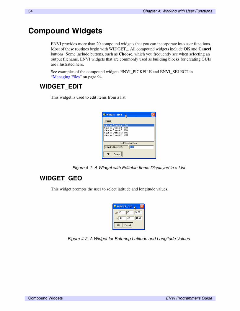
54 Chapter 4: Working with User Functions
Compound Widgets
ENVI provides more than 20 compound widgets that you can incorporate into user functions. Most of these routines begin with WIDGET_. All compound widgets include OK and Cancel buttons. Some include buttons, such as Choose, which you frequently see when selecting an output filename. ENVI widgets that are commonly used as building blocks for creating GUIs are illustrated here.
See examples of the compound widgets ENVI_PICKFILE and ENVI_SELECT in “Managing Files” on page 94.
WIDGET_EDIT
This widget is used to edit items from a list.
WIDGET_GEO
This widget prompts the user to select latitude and longitude values.
Figure 4-1: A Widget with Editable Items Displayed in a List
Figure 4-2: A Widget for Entering Latitude and Longitude Values
Compound Widgets ENVI Programmer’s Guide

Chapter 4: Working with User Functions 55
WIDGET_MAP
This widget is used to edit map coordinates and projections.
WIDGET_MENU
This widget is used to make a menu of exclusive or non-exclusive buttons. Exclusive buttons have round radio buttons, and non-exclusive buttons have square boxes with check marks.
Figure 4-3: A Widget for Editing Map Coordinates and Projections
Figure 4-4: A Widget with Exclusive Radio Buttons
ENVI Programmer’s Guide Compound Widgets

56 Chapter 4: Working with User Functions
WIDGET_MULTI
This widget is used to select multiple items from a list. ENVI uses it to select ROIs to use for a classification.
WIDGET_OUTF
This widget is used to select an output filename.
Figure 4-5: A Widget for Selecting Items from a List
Figure 4-6: A Widget for Selecting or Choosing an Output Filename
Compound Widgets ENVI Programmer’s Guide

Chapter 4: Working with User Functions 57
WIDGET_OUTFM
This widget is also used to select an output filename, but it provides the option to save the result to memory. If you select File, you can enter or choose an output filename.
WIDGET_PARAM
This widget is used for entering numeric parameters.
WIDGET_PMENU
This widget provides a drop-down list and is an alternative to using WIDGET_MENU with exclusive buttons.
Figure 4-7: A Widget for Selecting Output to File or Memory
Figure 4-8: A Widget for Entering Numeric Parameters
Figure 4-9: A Widget with a Drop-down List
ENVI Programmer’s Guide Compound Widgets
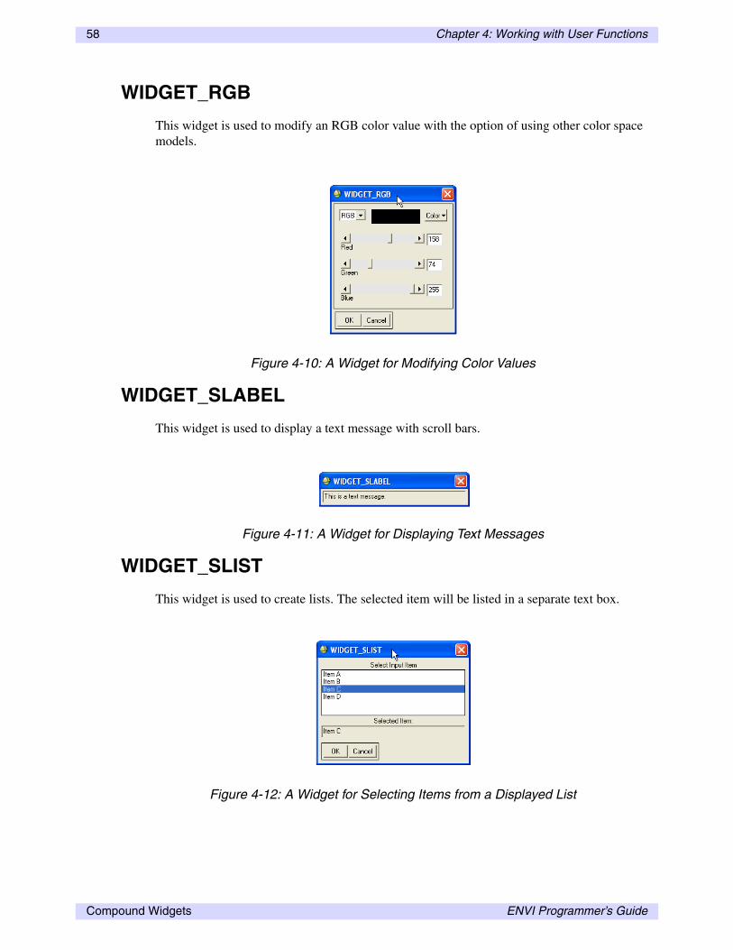
58 Chapter 4: Working with User Functions
WIDGET_RGB
This widget is used to modify an RGB color value with the option of using other color space models.
WIDGET_SLABEL
This widget is used to display a text message with scroll bars.
WIDGET_SLIST
This widget is used to create lists. The selected item will be listed in a separate text box.
Figure 4-10: A Widget for Modifying Color Values
Figure 4-11: A Widget for Displaying Text Messages
Figure 4-12: A Widget for Selecting Items from a Displayed List
Compound Widgets ENVI Programmer’s Guide

Chapter 4: Working with User Functions 59
WIDGET_SSLIDER
This widget is used to set a numeric value using a slider.
WIDGET_STRING
This widget is used to enter strings.
Figure 4-13: A Widget with a Slider for Specifying Numeric Values
Figure 4-14: A Widget for Entering Text
ENVI Programmer’s Guide Compound Widgets

60 Chapter 4: Working with User Functions
WIDGET_SUBSET
This widget contains a Spatial Subset button, which displays ENVI’s Select Spatial Subset dialog.
WIDGET_TOGGLE
This widget contains a toggle button.
Figure 4-15: A Standard Spatial Subset Widget
Figure 4-16: A Widget with an Arrow Toggle Button
Compound Widgets ENVI Programmer’s Guide
Chapter 4: Working with User Functions 61
Auto-Managed Widget Events
Ordinarily, user functions that include widgets must have separate routines to handle all of the events that the widgets might generate. These event-handling routines can be cumbersome and often confusing to code, especially for a relatively new programmer. To facilitate adding widgets to user functions, ENVI developers provided a mechanism for ENVI to automatically manage all of the events that originate from ENVI widgets. Two ENVI routines are central to allowing you to use auto-managed widgets.
WIDGET_AUTO_BASE
In ordinary IDL widget programming, all widget bases, including the top-level base (TLB), are created using the IDL function WIDGET_BASE. However, in ENVI programming, if you want to create widget hierarchies whose events are auto-managed by ENVI, you must use the the WIDGET_AUTO_BASE routine to create the TLB. All other bases used in building the GUI for the user function should be created with the IDL function WIDGET_BASE.
TLBs created using WIDGET_AUTO_BASE are automatically column-based, centered, and modal (blocking). Unlike WIDGET_BASE, which can accept dozens of different keywords controlling the appearance of the base, WIDGET_AUTO_BASE only accepts four keywords: GROUP, TITLE, XBIG, and YBIG. These keywords allow the GUI to be tied to an existing widget, to be given a title for the window bar, and to be automatically be offset if unusually wide or tall.
AUTO_WID_MNG
In an ordinary IDL widget program, once the GUI is defined, the XMANAGER procedure is called to register the widget and to begin monitoring for events that you would have to manage with a separate event handler procedure. However, for auto-managed widgets, you never need to call XMANAGER. Instead, you can call a special ENVI function called AUTO_WID_MNG, which internally registers the widget, monitors for events, and returns the user input to you as a structure variable. The AUTO_WID_MNG function also adds OK and Cancel buttons to the bottom of the widget.
This function is used as follows:
result = AUTO_WID_MNG(TLB)
The argument of the function (TLB) must be a widget base created with WIDGET_AUTO_BASE. When the user function’s GUI is dismissed (for example, by clicking OK to proceed with the routine), RESULT is set to a structure variable that contains a special tag for each widget used in the GUI. The name of each tag in the structure is defined by the user value (specified by the UVALUE keyword) assigned to each ENVI compound widget when the GUI was defined.
ENVI Programmer’s Guide Auto-Managed Widget Events

62 Chapter 4: Working with User Functions
This technique gives user functions a very simple form:
PRO MyUserFunction, Event TLB = WIDGET_AUTO_BASE(...) 1st_parameter = WIDGET_PARAM(TLB, uvalue='param1'...) result = AUTO_WID_MNG(TLB) do the processing...END
In this example, the value of result.param1 contains the information you entered into the WIDGET_PARAM widget. See the ENVI Reference Guide for descriptions of each compound widget, including the type of information returned by the widget. In addition to tags for each ENVI widget used in the GUI, the RESULT structure always contains a tag called ACCEPT, which is set to 1 if you click OK or 0 if you click Cancel.
If you prefer, you can write your own event-handling routines for your user functions. If you do this, you can still use the ENVI compound widgets in your code. The ENVI widget produces an event structure with an extra tag called RESULT that contains the information entered into the widget. There are some cases when it is preferable to write your own event-handling procedures, for example, if you need to create a user function whose GUI is not modal. However, you can write most user functions without this additional detail.
Example: Building a Simple GUI with Auto-Managed Widgets
This example demonstrates how to build a GUI and work with the result structure. This user function collects two numeric parameters and prompts the user to add or multiply them. Call this user function TEST_WIDGETS.
1. Open the envi.men file and add an item under the MyFuntions menu:
1 {Test Widgets} {not used} {test_widgets}
2. Save the menu file.
3. Restart ENVI. In the IDLDE window that is running the ENVI session, open a new editor window.
4. In the new editor window, enter the following user function code:
PRO test_widgets, event COMPILE_OPT STRICTARR TLB = WIDGET_AUTO_BASE(title='widget test') p1 = WIDGET_PARAM(tlb, /auto_manage, dt=4, field=2, $ prompt='enter the first parameter', uvalue='p1') p2 = WIDGET_PARAM(tlb, /auto_manage, dt=4, field=2, $ prompt='enter the second parameter', uvalue='p2') operation = WIDGET_TOGGLE(tlb, /auto_manage, default=0, $ list=['add', 'multiply'], prompt='operation', $ uvalue='operation') result=AUTO_WID_MNG(TLB) IF (result.accept eq 0) THEN return IF (result.operation eq 0) THEN $ ENVI_INFO_WID, STRTRIM(result.p1 + result.p2) ELSE $ ENVI_INFO_WID, STRTRIM(result.p1 * result.p2)END
5. Save the file as test_widgets.pro in the save_add directory.
6. Compile the user function to ensure there are no syntax errors.
Auto-Managed Widget Events ENVI Programmer’s Guide

Chapter 4: Working with User Functions 63
7. After compilation, place your cursor on the line at the bottom of the code that begins with:
IF (result.operation eq 0) THEN $
8. Then, from the Run menu in the IDLDE, select Set Breakpoint. You should see a yellow circle appear next to this line in the Editor window. Setting a breakpoint allows you to execute the user function, but it stops at the line where the breakpoint occurs. This allows you to examine some of the variables created within TEST_WIDGETS.
9. After the breakpoint is set, try running TEST_WIDGETS. You can execute the function by using the menu item under MyFunctions, or by using the Run button on the Editor toolbar.
10. When the widget interface appears, pay particular attention to the layout of the widgets. For example, examine the widget to see if the toggle button appears on one line or two, whether the widget GUI looks the same as ENVI’s GUIs, and to see if the widget interface could be organized better.
It takes some practice to control the layout of any widget interface. It is usually possible to force widgets to appear on a single line by putting them into their own widget base that is defined as a row base instead of a column base.
11. After you fill in values and select an operation, click the OK button. The user function should now halt execution because of the breakpoint.
12. In the IDLDE, use the Variable Watch Window to examine the RESULT variable, or use the HELP command:
help, result, /struct
** Structure <bed2b8>, 4 tags, length=24, refs=1:P1 DOUBLE 32.000000P2 DOUBLE 24.800000OPERATION INT 1ACCEPT INT 1
13. The result structure contains four tags, one for each of the two WIDGET_PARAMS (P1 and P2), one for the WIDGET_TOGGLE (OPERATION), and one to indicate which of the OK and Cancel buttons was clicked (ACCEPT). Note that the tag names are the same as the user values for the widgets. The ACCEPT tag is always automatically added to the result structure.
The values RESULT.P1 and RESULT.P2 are set to the entered parameters, RESULT.OPERATION is set to the index into the LIST array that corresponds to the value selected (0 for add and 1 for multiply), and RESULT.ACCEPT is set to 1 to indicate the user clicked OK. If the ACCEPT tag is set to 0, then the user clicked Cancel. If this occurs, then the user function returns in the next line.
Also note that the numeric data returned by AUTO_WID_MNG are double-precision values. This is always the case for numeric data collected by ENVI’s AUTO_WID_MNG routine, so in some cases, you may need to change the data type to something more appropriate for your needs.
14. From the IDLDE Run menu, select Step Out to continue executing the user function.
The results of the operation are displayed in an ENVI report widget created with the function ENVI_INFO_WID. This is a special widget routine that makes a simple
ENVI Programmer’s Guide Auto-Managed Widget Events

64 Chapter 4: Working with User Functions
dialog window in which to display text reports. This widget is not modal; that is, the widget does not block the rest of ENVI from functioning.
15. With a few minor modifications, you can significantly improve the appearance of the widget interface. Make the following changes to the TEST_WIDGETS routine (highlighted by line comments in the following code).
PRO TEST_WIDGETS, event
COMPILE_OPT STRICTARR
TLB = WIDGET_AUTO_BASE(title='widget test')
;+++++++++++++++BEGIN: Code Modification+++++++++++++++ row_base1 = WIDGET_BASE(TLB, /row) p1 = WIDGET_PARAM(row_base1, /auto_manage, dt=4, $ ;++++++++++++++++END: Code Modification++++++++++++++++ field=2, prompt='enter the first parameter', $ uvalue='p1')
;+++++++++++++++BEGIN: Code Modification+++++++++++++++ row_base2 = WIDGET_BASE(TLB, /row) p2 = WIDGET_PARAM(row_base2, /auto_manage, dt=4, $ ;++++++++++++++++END: Code Modification++++++++++++++++ field=2, prompt='enter the second parameter', $ uvalue='p2')
;+++++++++++++++BEGIN: Code Modification+++++++++++++++ row_base3 = WIDGET_BASE(TLB, /row) operation = WIDGET_TOGGLE(row_base3, /auto_manage, $ ;++++++++++++++++END: Code Modification++++++++++++++++ default=0, list=['add', 'multiply'], $ prompt='operation', uvalue='operation') result=AUTO_WID_MNG(TLB)
IF (result.operation EQ 0) THEN $ ENVI_INFO_WID, STRTRIM(result.p1 + result.p2) ELSE $ ENVI_INFO_WID, STRTRIM(result.p1 * result.p2)
END
16. Save the user function code (overwriting the original version in the save_add directory), and compile it to ensure there are no syntax errors.
17. Place the cursor on the line containing the breakpoint, then from the Run menu, select Clean Breakpoint.
18. Now, try running the modified version of the TEST_WIDGETS user function.
Note that the widget layout has changed so that all of the individual widgets now appear on only one line.
Auto-Managed Widget Events ENVI Programmer’s Guide

Chapter 4: Working with User Functions 65
Trapping Errors in User Functions
Whenever possible, potential errors that could occur when executing a user function should be trapped internally to prevent ENVI from crashing. While it is impossible (and unreasonably time-consuming) to account for every possibility, there are several quick and easy ways of preventing the most common problems. General guidelines include the following:
• When a widget includes a Cancel button (every ENVI_SELECT, ENVI_PICKFILE, and AUTO_WID_MNG widget has one), always check to see if it was selected. This type of error checking is very easy to implement and should always be included in a user function.
• Wherever possible, hard code default values into widgets or algorithms in case the user leaves a required value undefined.
• When using the WHERE function, always use the optional COUNT parameter to ensure a valid result was returned.
Input/Output Error Handling
Although not a requirement, you should properly handle I/O errors in all user functions. Use the IDL routine ON_IOERROR, which specifies a jump to statement when an I/O error occurs. If ON_IOERROR is called and an I/O error occurs later in the same procedure activation, control is transferred to the designated statement with the error code stored in the system variable !ERROR_STATE. The text of the error message is contained in !ERROR_STATE.MSG.
The IDL routine CATCH provides a more generalized mechanism for handling exceptions and errors. The advantage of CATCH is that it traps not only I/O errors but also any programming errors such as undefined variables, invalid array subscripts, or undefined functions.
ENVI uses a mix of ON_IOERROR and CATCH for error handling. Library routines internally use ON_IOERROR with a CATCH mechanism setup prior to the routine call. Any I/O errors are handled within the routine, but other programming errors are handled externally. In order to follow this model, the event handler establishes a CATCH mechanism after getting the processing parameters and prior to calling the library routine.
The ENVI routine ENVI_IO_ERROR reports I/O errors and provides an option to delete the output file being created. Using this routine keeps the user function I/O error display consistent with ENVI.
The following example summarizes the use of the error handling routines.
Example: Input/Output Error Handling
This example illustrates the combined use of ON_IOERROR and ENVI_IO_ERROR to trap and display I/O errors. All user functions should perform these basic steps. The following steps outline a technique for handling I/O errors.
1. At the start of the routine, clear the system error code !ERROR_STATE using the MESSAGE routine, and declare the jump location for an I/O error.
ENVI Programmer’s Guide Trapping Errors in User Functions

66 Chapter 4: Working with User Functions
2. When the processing is complete, clear the system error code !ERROR_STATE, using the MESSAGE routine to remove any non-fatal errors.
3. Determine if there was an I/O error and print the error message.
4. Delete the current output file specified by the file unit number UNIT.
You can use the following model to handle I/O errors. This is just one suggested method; many other effective techniques are available.
PRO user_function, [parameters and keywords] message, /reset on_ioerror, trouble Initialization and Processing ...message,/resettrouble: IF (!error_state.code NE 0) THEN $ ENVI_IO_ERROR, 'User Function', unit=unit IF (!error_state.code EQ 0) THEN $ Write an ENVI header END
Using CATCH for Unexpected Non-Input/Output Errors
The IDL routine CATCH allows you to use IDL’s internal error-catching mechanism to make a generic error handler that prevents a crash when an unexpected error condition occurs. The IDL system variable !ERROR_STATE contains information about the last error, including the internal error code (!ERROR_STATE.CODE) and the text of the error message (!ERROR_STATE.MSG). Each time an IDL error occurs, this system variable is updated. CATCH’s usage is simple:
CATCH, error
When CATCH is called, the ERROR variable is set to 0. However, when an error condition occurs, ERROR is set to the internal error code !ERROR_STATE.CODE, and the IDL procedure (the ENVI user function) jumps immediately to the line of the program where the CATCH procedure was called and continues executing from there. At this point, you can use the information in the !ERROR_STATE system variable to display a message about the error and prompt the user to choose how to proceed.
The following code example works well as a generic error handler when placed at the beginning of a user function:
CATCH, errorIF (error NE 0) THEN BEGIN ok = DIALOG_MESSAGE(!error_state.msg, /cancel) IF (STRUPCASE(ok) EQ 'CANCEL') THEN returnENDIF
Trapping Errors in User Functions ENVI Programmer’s Guide

Chapter 4: Working with User Functions 67
Using Processing Routines and Tiling
Processing routines in ENVI take input image data, process the data, and output a new image, plot, or report. ENVI commonly refers to these as the “DOIT” portions of a user function.
ENVI processing routines are usually combined with ENVI’s tiling methodology to handle images of any spatial or spectral size. Tiles can be spatial or spectral with the size of a spatial tile defined in the configuration file. The size of a spectral tile is always the number of samples times the number of bands.
All ENVI user functions can use the built-in tiling functions to get data. This ensures that the processing function operates on any size data file, both spatially and spectrally. ENVI tiles come in three formats: BSQ (number of samples by number of tile lines), BIL (number of samples by number of bands), or BIP (number of bands by number of samples). BIL and BIP tiles differ only by a transpose:
BIL tile = transpose(BIP tile)
ENVI also provides routines that display a processing status dialog, reporting the percentage of processing completed. See “Processing Status Report” on page 78.
ENVI also allows non-tiled processing. However, this is not a recommended solution because it does not always work for large images. Nevertheless, non-tiled processing is a quick way to access data without the overhead of setting up tiling operations, and it can be used as a prototyping technique (see “Non-Tiled Processing Routines” on page 76).
All processing functions should include both error handling and status reports as common practice. The next sections break down the processing routine into basic components, and they discuss the available ENVI routines.
NoteCreating the processing routine as a separate procedure from the menu event handler and processing parameter input allows the routine to be called directly with all supplied arguments. See “Overview of Batch Mode” on page 30.
ENVI Programmer’s Guide Using Processing Routines and Tiling
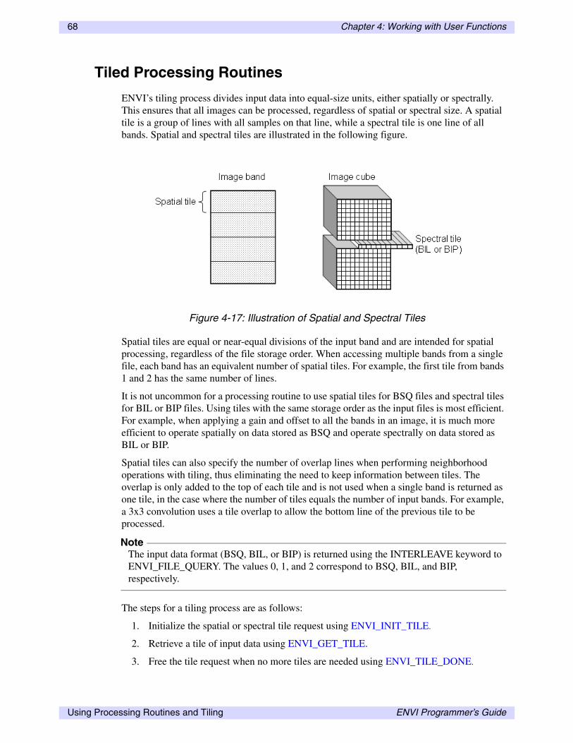
68 Chapter 4: Working with User Functions
Tiled Processing Routines
ENVI’s tiling process divides input data into equal-size units, either spatially or spectrally. This ensures that all images can be processed, regardless of spatial or spectral size. A spatial tile is a group of lines with all samples on that line, while a spectral tile is one line of all bands. Spatial and spectral tiles are illustrated in the following figure.
Spatial tiles are equal or near-equal divisions of the input band and are intended for spatial processing, regardless of the file storage order. When accessing multiple bands from a single file, each band has an equivalent number of spatial tiles. For example, the first tile from bands 1 and 2 has the same number of lines.
It is not uncommon for a processing routine to use spatial tiles for BSQ files and spectral tiles for BIL or BIP files. Using tiles with the same storage order as the input files is most efficient. For example, when applying a gain and offset to all the bands in an image, it is much more efficient to operate spatially on data stored as BSQ and operate spectrally on data stored as BIL or BIP.
Spatial tiles can also specify the number of overlap lines when performing neighborhood operations with tiling, thus eliminating the need to keep information between tiles. The overlap is only added to the top of each tile and is not used when a single band is returned as one tile, in the case where the number of tiles equals the number of input bands. For example, a 3x3 convolution uses a tile overlap to allow the bottom line of the previous tile to be processed.
NoteThe input data format (BSQ, BIL, or BIP) is returned using the INTERLEAVE keyword to ENVI_FILE_QUERY. The values 0, 1, and 2 correspond to BSQ, BIL, and BIP, respectively.
The steps for a tiling process are as follows:
1. Initialize the spatial or spectral tile request using ENVI_INIT_TILE.
2. Retrieve a tile of input data using ENVI_GET_TILE.
3. Free the tile request when no more tiles are needed using ENVI_TILE_DONE.
Figure 4-17: Illustration of Spatial and Spectral Tiles
Using Processing Routines and Tiling ENVI Programmer’s Guide

Chapter 4: Working with User Functions 69
The following examples detail the use of the tiling routines and issues related to input file storage order. In all examples, the returned TILE_ID from ENVI_INIT_TILE is a unique reference ID associated with the requested tiles that is used by the other tile routines. A FOR loop is then used to loop over the total number of tiles (NUM_TILES returned from the tile initialization). Within the FOR loop, the current tile, band index, and tile data information are printed to the IDL Output Log window. Once all the tiles have been retrieved, the tile request is freed using ENVI_TILE_DONE.
Example: Spatial Tiling
Tiling routines that process only spatial tiles should not be concerned with the input data storage order. Tiles are initialized as spatial tiles, and each tile is processed in the same way. The tile initialization routine needs the file ID, the selected bands, and the spatial dimensions. ENVI_SELECT returns all of these parameters when you select an input file.
The routine in the following example uses ENVI_SELECT to choose the input file, returning the FID, POS, and DIMS variables as inputs to ENVI_INIT_TILE. For spatial tiles, the interleave value is 0 (BSQ), regardless of the data interleave. The following sample code is also available in the file uftile1.pro in the lib directory of the ENVI installation.
pro spat_tile envi_select, title='Input Filename', fid=fid, $ pos=pos, dims=dims if (fid eq -1) then return tile_id = envi_init_tile(fid, pos, interleave=0, $ num_tiles=num_tiles, xs=dims[1], xe=dims[2], $ ys=dims[3], ye=dims[4]) for i=0L, num_tiles-1 do begin data = envi_get_tile(tile_id, i, band_index=band_index) print, i, band_index help, data endfor envi_tile_done, tile_idend
As you can see, all spatial tiling is performed the same way, regardless of the data storage order. To execute this example:
1. Save the routine to a file and place it in the save_add directory.
2. Start or restart ENVI.
3. Open the IDL development environment (PC) or the shell window where ENVI was started (UNIX, Mac OS X).
4. Type the following at the ENVI command line:
spat_tile
5. Choose an input file and look at the messages displayed in the IDL Output Log window.
NoteThe band index returned from ENVI_GET_TILE references the POS array, and the actual file band number is POS[band_index].
ENVI Programmer’s Guide Using Processing Routines and Tiling

70 Chapter 4: Working with User Functions
Example: Spectral Tiles
Tiling routines that process only spectral tiles should use BIL and BIP tile interleaves for optimal performance. The dimensions of a BIL slice are always [number of samples, number of bands]. A BIP slice is the transpose of the BIL slice, so dimensions are [number of bands, number of samples]. The tile initialization routine needs the file ID, selected bands, and spatial dimensions. ENVI_SELECT returns all of these parameters when you select an input file.
NoteIf performance is not an issue, then you should always use BIL tiles.
The routine in the following example uses ENVI_SELECT to choose the input file, returning the selected FID, POS and DIMS variables for inputs to ENVI_INIT_TILE. The spectral tiles in this example use BIL tiles for data in BSQ or BIL interleave and BIP tiles for data in BIP interleave. The input data interleave format is returned using the INTERLEAVE keyword to ENVI_FILE_QUERY. The following sample code is also available in the file uftile2.pro in the lib directory of the installation.
pro spec_tile envi_select, title='Input Filename', fid=fid, $ pos=pos, dims=dims if (fid eq -1) then return envi_file_query, fid, interleave=interleave tile_id = envi_init_tile(fid, pos, num_tiles=num_tiles, $ interleave=(interleave > 1), xs=dims[1], xe=dims[2], $ ys=dims[3], ye=dims[4]) for i=0L, num_tiles-1 do begin data = envi_get_tile(tile_id, i) print, i help, data endfor envi_tile_done, tile_idend
To execute this example:
1. Save the routine to a file and place it in the save_add directory.
2. Start or restart ENVI.
3. Open the IDL development environment (PC) or the shell window where ENVI was started (UNIX, Mac OS X).
4. Type the following at the ENVI command line:
spec_tile
5. Choose an input file and look at the messages displayed in the IDL Output Log window.
NoteThe greater than operator (>) used in the call to ENVI_INIT_TILE returns the greater of its two arguments. For details, see ENVI_INIT_TILE.
Using Processing Routines and Tiling ENVI Programmer’s Guide
Chapter 4: Working with User Functions 71
Example: Spatial and Spectral Tiles
Tiling routines that process either spatial or spectral tiles should set the tile interleave equal to the file interleave. For example, a gain and offset correction applied to every band in an image could be applied using any of the file interleaves. With a BSQ interleave, the current gain and offset values are based on the band index of the current tile. BIL and BIP tile interleaves apply gains and offsets as vectors to every band in the current tile. The tile initialization routine needs the file ID, selected bands, and spatial dimensions. ENVI_SELECT returns all of these parameters when used to select the input file and is used in this example. For details, see ENVI_INIT_TILE. The input image’s interleave is found using the INTERLEAVE keyword to ENVI_FILE_QUERY.
The following sample code is also available in the file uftile3.pro in the lib directory of the ENVI installation.
pro ss_tile envi_select, title='Input Filename', fid=fid, $ pos=pos, dims=dims if (fid eq -1) then return envi_file_query, fid, interleave=interleave tile_id = envi_init_tile(fid, pos, num_tiles=num_tiles, $ interleave=interleave, xs=dims[1], xe=dims[2], $ ys=dims[3], ye=dims[4]) for i=0L, num_tiles-1 do begin data = envi_get_tile(tile_id, i) ; Sample case statement for BSQ, BIL and BIP tiles case interleave of 0: 1: 2: endcase print, i help, data endfor envi_tile_done, tile_idend
To execute this example.
1. Save the routine to a file and place it in the save_add directory.
2. Start or restart ENVI.
3. Open the IDL development environment (PC) or the shell window where ENVI was started (UNIX, Mac OS X).
4. Type the following at the ENVI command line:
ss_tile
5. Choose an input file and look at the messages displayed in the IDL Output Log window.
ENVI Programmer’s Guide Using Processing Routines and Tiling

72 Chapter 4: Working with User Functions
Saving the Results
This section discusses how to save image results from tiled processing. For information on outputting results to plots, see “Plotting” on page 85. For information on outputting results to a report, see “Reports” on page 90. You can write image results to a file or memory; ENVI allows both options whenever possible. When writing results to a file, you should write the result with the same interleave as the tile processing. Tiles processed using spatial BSQ tiles generate BSQ results; similarly, BIL tiles generate BIL results. Following this simplification, the processed tiles are written directly to files without the need to convert interleave formats.
Output files are opened for writing using the IDL routine OPENW. Prior to calling OPENW, a file unit number is allocated using GET_LUN. The tile data are written to the file using the IDL routine WRITEU, which writes the specified array of data in binary format. After all data are written to the file, the file is closed and the file unit number is deallocated using the IDL routine FREE_LUN.
Once the file is written to disk, the ENVI routine ENVI_SETUP_HEAD is used to write an ENVI header and optionally open the file. The following file information is required to write the header: filename, number of samples (ns), number of lines (nl), number of bands (nb), offset, interleave, and data type. Although optional, you should also supply the x and y starting pixel, text description, band names, and inheritance. The optional OPEN keyword opens the file and loads the contents into the Available Bands List. Remember to use the WRITE keyword to write the header file to disk. Otherwise, it is stored in memory only and will be lost when the IDL session ends.
NoteAdditional information is required for special file types, such as classification and spectral libraries. See ENVI_SETUP_HEAD for more information.
For memory output, the result is stored in an allocated array in memory. The processed data from each tile are inserted into the appropriate storage location. The dimensions of a memory array are always [ns, nl, nb]. The IDL functions BYTARR, INTARR, LONARR, FLTARR, DBLARR, and MAKE_ARRAY are used to create memory arrays of type byte, integer, long integer, floating-point, double-precision, and arbitrary, respectively.
When the processing is completed and the memory array contains the processed result, the array is passed into ENVI using the routine ENVI_ENTER_DATA. At a minimum, only the memory array is required. Although optional, you should also supply the x and y starting pixel, text description, band names, and inheritance.
The following examples detail the use of writing header files and entering memory results.
Example: Saving Spatial Tiles to Disk
The “Example: Spatial Tiling” on page 69 is modified in the example below to save the resulting tiles to disk and to write an ENVI header file. The new modifications are as follows:
1. Accept an output filename as a parameter.
2. Open the output file and write the result.
3. Call ENVI_SETUP_HEAD to write an ENVI header file.
Using Processing Routines and Tiling ENVI Programmer’s Guide

Chapter 4: Working with User Functions 73
The IDL procedure OPENW is used to open the output filename, and the keyword GET_LUN allocates an LUN. Within the tile processing loop, each returned data tile is written to disk using the IDL procedure WRITEU, which uses the LUN and the tile data array as arguments. The tile data are written in binary format using the data type of the tile data array. Since no actual processing is performed, the tile data type remains the same as the input data type (the value returned from ENVI_FILE_QUERY using the DATA_TYPE keyword).
NoteTile processing may change the data type; be sure to check that the output data type is what you expect.
After writing all data to the output file, close the file and free the allocated file unit number using the IDL procedure FREE_LUN. The ENVI header file is written using ENVI_SETUP_HEAD. The below example specifies both the required keywords FNAME, NS, NL, NB, DATA_TYPE, OFFSET and INTERLEAVE, and the optional keywords XSTART, YSTART, and DESCRIP.
The following sample code is also available in the file uftile4.pro in the lib directory of the installation.
pro spat_disk, out_name ; Check for an output filename if (n_elements(out_name) eq 0) then begin print, 'Please specify a valid output filename' return endif envi_select, title='Input Filename', fid=fid, $ pos=pos, dims=dims if (fid eq -1) then return envi_file_query, fid, data_type=data_type, xstart=xstart,$ ystart=ystart ns = dims[2] - dims[1] + 1 nl = dims[4] - dims[3] + 1 nb = n_elements(pos) openw, unit, out_name, /get_lun tile_id = envi_init_tile(fid, pos, interleave=0, $ num_tiles=num_tiles, xs=dims[1], xe=dims[2], $ ys=dims[3], ye=dims[4]) for i=0L, num_tiles-1 do begin data = envi_get_tile(tile_id, i, band_index=band_index) print, i, band_index writeu, unit, data endfor free_lun, unit envi_setup_head, fname=out_name, ns=ns, nl=nl, nb=nb, $ data_type=data_type, offset=0, interleave=0, $ xstart=xstart+dims[1], ystart=ystart+dims[3], $ descrip='Test routine output', /write, /open envi_tile_done, tile_idend
To execute this example:
1. Save the procedure to a file and place it in the save_add directory.
2. Start or restart ENVI.
ENVI Programmer’s Guide Using Processing Routines and Tiling

74 Chapter 4: Working with User Functions
3. Open the IDL development environment (PC) or the shell window where ENVI was started (UNIX, Mac OS X).
4. Type the following at the ENVI command line to save the tiles to disk, where filename is a valid output file name:
spat_disk, 'filename'
5. Choose an input file.
6. The resulting image is added to the Available Bands List.
Example: Saving Spatial Tiles to Memory
The “Example: Saving Spatial Tiles to Disk” on page 72 is modified in the example below to save the resulting tiles to memory. Data are then entered into ENVI using ENVI_ENTER_DATA.
The IDL function MAKE_ARRAY is used to allocate an output memory array for the tiled data. In this example, the output array is the same data type as the input, so the TYPE keyword to MAKE_ARRAY is set to the data type returned form ENVI_FILE_QUERY.
NoteThe output data type is not always the same as the input data type. It depends upon the processing routine and the range of the output data.
To save each tile into the output array, the band index and y start value returned from ENVI_GET_TILE are used to index into the appropriate array location. The y start value is in file coordinates, and any spatial line subset (specified by DIMS[3]) must be subtracted. After saving all the tile data into the output memory array, the data are entered into ENVI using ENVI_ENTER_DATA. The below example uses this routine’s optional keywords, XSTART, YSTART, and DESCRIP. This sample code is also available in the file uftile5.pro in the lib directory of the installation.
pro spat_mem envi_select, title='Input Filename', fid=fid, $ pos=pos, dims=dims if (fid eq -1) then return envi_file_query, fid, data_type=data_type, xstart=xstart,$ ystart=ystart ns = dims[2] - dims[1] + 1 nl = dims[4] - dims[3] + 1 nb = n_elements(pos) mem_res = make_array(ns, nl, nb, type=data_type, /nozero) tile_id = envi_init_tile(fid, pos, interleave=0, $ num_tiles=num_tiles, xs=dims[1], xe=dims[2], $ ys=dims[3], ye=dims[4]) for i=0L, num_tiles-1 do begin data = envi_get_tile(tile_id, i, band_index=band_index, $ ys=ys) print, i, band_index mem_res[0,ys-dims[3],band_index] = data endfor envi_enter_data, mem_res, xstart=xstart+dims[1], $ ystart=ystart+dims[3], descrip='Test routine output' envi_tile_done, tile_idend
Using Processing Routines and Tiling ENVI Programmer’s Guide

Chapter 4: Working with User Functions 75
To execute this example:
1. Save the procedure to a file and place it in the save_add directory.
2. Start or restart ENVI.
3. Open the IDL development environment (PC) or the shell window where ENVI was started (UNIX, Mac OS X).
4. Type the following at the ENVI command line to save the tiles to memory:
spat_mem
5. Choose an input file.
6. The resulting image is added to the Available Bands List.
Example: Saving Spectral Tiles to Disk
The “Example: Saving Spatial Tiles to Disk” on page 72 is modified in the below example to save spectral tiles to disk.
The IDL procedure OPENW is used to open the output filename, and the keyword GET_LUN allocates an LUN. Within the tile processing loop, each returned data tile is written to disk using the IDL procedure WRITEU, which uses the LUN and the tile data array as arguments. The tile data are written in binary format using the data type of the tile data array. Since no actual processing is performed, the tile data type remains the same as the input data type (the value returned from ENVI_FILE_QUERY using the DATA_TYPE keyword).
NoteTile processing may change the data type, so be sure to check that the output data type is what you expected.
Writing each tile in the data tile interleave also preserves the file interleave. Both the input and output file have the same interleave. The input file interleave is returned from ENVI_FILE_QUERY using the INTERLEAVE keyword.
After writing all data to the output file, close the file and free the allocated file unit number using the IDL procedure FREE_LUN. The ENVI header file is written using ENVI_SETUP_HEAD. The below example specifies both the required keywords FNAME, NS, NL, NB, DATA_TYPE, OFFSET and INTERLEAVE, and the optional keywords XSTART, YSTART, and DESCRIP.
The following sample code is also available in the file uftile6.pro in the lib directory of the installation.
pro spec_disk, out_name ; Check for an output filename if (n_elements(out_name) eq 0) then begin print, 'Please specify a valid output filename' return endif envi_select, title='Input Filename', fid=fid, $ pos=pos, dims=dims if (fid eq -1) then return envi_file_query, fid, data_type=data_type, xstart=xstart,$ ystart=ystart, interleave=interleave ns = dims[2] - dims[1] + 1
ENVI Programmer’s Guide Using Processing Routines and Tiling
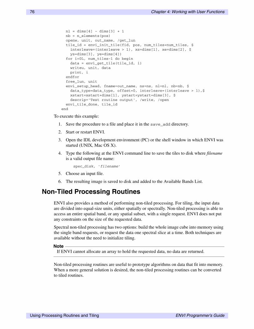
76 Chapter 4: Working with User Functions
nl = dims[4] - dims[3] + 1 nb = n_elements(pos) openw, unit, out_name, /get_lun tile_id = envi_init_tile(fid, pos, num_tiles=num_tiles, $ interleave=(interleave > 1), xs=dims[1], xe=dims[2], $ ys=dims[3], ye=dims[4]) for i=0L, num_tiles-1 do begin data = envi_get_tile(tile_id, i) writeu, unit, data print, i endfor free_lun, unit envi_setup_head, fname=out_name, ns=ns, nl=nl, nb=nb, $ data_type=data_type, offset=0, interleave=(interleave > 1),$ xstart=xstart+dims[1], ystart=ystart+dims[3], $ descrip='Test routine output', /write, /open envi_tile_done, tile_idend
To execute this example:
1. Save the procedure to a file and place it in the save_add directory.
2. Start or restart ENVI.
3. Open the IDL development environment (PC) or the shell window in which ENVI was started (UNIX, Mac OS X).
4. Type the following at the ENVI command line to save the tiles to disk where filename is a valid output file name:
spec_disk, 'filename'
5. Choose an input file.
6. The resulting image is saved to disk and added to the Available Bands List.
Non-Tiled Processing Routines
ENVI also provides a method of performing non-tiled processing. For tiling, the input data are divided into equal-size units, either spatially or spectrally. Non-tiled processing is able to access an entire spatial band, or any spatial subset, with a single request. ENVI does not put any constraints on the size of the requested data.
Spectral non-tiled processing has two options: build the whole image cube into memory using the single band requests, or request the data one spectral slice at a time. Both techniques are available without the need to initialize tiling.
NoteIf ENVI cannot allocate an array to hold the requested data, no data are returned.
Non-tiled processing routines are useful to prototype algorithms on data that fit into memory. When a more general solution is desired, the non-tiled processing routines can be converted to tiled routines.
Using Processing Routines and Tiling ENVI Programmer’s Guide

Chapter 4: Working with User Functions 77
The two routines used to access non-tiled spatial and spectral data are ENVI_GET_DATA and ENVI_GET_SLICE, respectively.
The following examples illustrate the use of these routines.
Example: Non-tiled Spatial Processing
This example interactively requests a band of spatial data. The routine ENVI_SELECT is used to choose the input data.
1. Start ENVI.
2. Open an multi-band image file.
3. Open the IDL development environment (PC) or the shell window in which ENVI was started (UNIX, Mac OS X).
4. Type the following on the ENVI command line to select a file:
ENVI_SELECT, title='Input Filename', fid=fid, pos=pos, $ dims=dims
5. Type the following at the ENVI command line to return the first band of data:
data = ENVI_GET_DATA(fid=fid, dims=dims, pos=pos[0])
6. Verify the return of the data using the help command:
help, data
7. If the number of elements of POS is greater than one, then type the following at the ENVI command line to return the second band of data:
data = ENVI_GET_DATA(fid=fid, dims=dims, pos=pos[1])
This interactive example is for demonstration purposes only. In practice, these steps are part of the processing routine.
Example: Non-tiled Spectral Processing
This example interactively requests a spectral data slice, which is a single line of all bands. Both BIL [ns, nb] and BIP [nb, ns] slices can be requested. The routine ENVI_SELECT is used to choose the band of data to request.
1. Start ENVI.
2. Open a multi-band image file.
3. Open the IDL development environment (PC) or the shell window in which ENVI was started (UNIX, Mac OS X).
4. Type the following at the ENVI command line to select a file:
ENVI_SELECT, title='Input Filename', fid=fid, pos=pos, $ dims=dims
5. Type the following at the ENVI command line to get a BIL slice of data for the first line:
data = ENVI_GET_SLICE(fid=fid, pos=pos, line=dims[3], $ xs=dims[1], xe=dims[2], /bil)
ENVI Programmer’s Guide Using Processing Routines and Tiling

78 Chapter 4: Working with User Functions
6. Verify the return of the data using the help command:
help, data
7. Type the following at the ENVI command line to get a BIP slice of data for the last line:
data = ENVI_GET_SLICE(fid=fid, pos=pos, line=dims[4], $ xs=dims[1], xe=dims[2], /bip)
This interactive example is for demonstration purposes only. In practice, these steps are part of the processing routine.
Processing Status Report
The processing status dialog shows the percent completed for the current processing. Using the ENVI processing status reports, you have control over the increment size and the update frequency. The optional Cancel button aborts processing on the next increment update. The processing status is controlled by three routines:
• ENVI_REPORT_INC: Set the report increment
• ENVI_REPORT_INIT: Initialize the report dialog
• ENVI_REPORT_STAT: Update the percent completed and check for cancellation.
NoteProcessing is aborted on the next increment update, unless the increment is 100% or the final increment is processing; then cancellation is ignored.
Each element of the string array argument to ENVI_REPORT_INIT is displayed on a separate line in the processing status dialog. ENVI typically uses a two-element array indicating the input and output file. To remain consistent, the array is set as follows, where filename is the actual input or output filename:
['Input File: filename', 'Output File: filename']
For items that are output to memory, the array is set as follows:
['Input File: filename', 'Output to Memory']
The processing status dialog is usually updated inside the tiling loop, which loops over the total number of tiles. For these cases, the report increment is set to the total number of tiles. For example, for five tiles, the report increment is set to 5, which implies 20% increments.
Example: Processing Status Dialog
This example interactively creates a processing status dialog and updates the percent completed.
1. Start ENVI.
2. Open the IDL development environment (PC, Macintosh) or the shell window in which ENVI was started (UNIX).
3. Type the following at the ENVI command line to create the Status dialog:
ENVI_REPORT_INIT, ['Input File: filename', $ 'Output File: filename'], title='Test Status', base=base
Using Processing Routines and Tiling ENVI Programmer’s Guide

Chapter 4: Working with User Functions 79
4. The following dialog should now be on the screen:
5. Now set the increment to 3 and update the percent completed using ENVI_REPORT_STAT. Type the following at the ENVI command line to set the increment:
ENVI_REPORT_INC, base, 3
6. Type the following at the ENVI command line to update the percent completed to 33%, 66%, and 99%:
ENVI_REPORT_STAT, base, 1, 3ENVI_REPORT_STAT, base, 2, 3ENVI_REPORT_STAT, base, 3, 3
7. Type the following at the ENVI command line to delete the status dialog:
ENVI_REPORT_INIT, base=base, /finish
This interactive example is for demonstration purposes only. In practice, these steps are part of the processing routine. When used with a tiled processing routine, the increment is typically the number of tiles being processed, and the report is updated before the next tile is requested. For non-tiled processing, the increment and report updates can be related to any processing loop used.
Figure 4-18: Processing Status Dialog
ENVI Programmer’s Guide Using Processing Routines and Tiling

80 Chapter 4: Working with User Functions
Adapting User Functions for ENVI
You can compile .pro files within ENVI only if you have ENVI + IDL. If you have standalone ENVI, you must create a (.sav) to add a user function. Before creating a .sav file, the user function may need some important modifications.
Using FORWARD_FUNCTION or COMPILE_OPT STRICTARR
See “Example: Using COMPILE_OPT” on page 34 for details on properly dereferencing variables.
Using RESOLVE_ALL to Find and Compile Dependent Routines
Many common IDL routines are not actually built into IDL as part of the binary IDL application, but they are included in the IDL library (or lib) as .pro code. For example, XMANAGER, CONGRID, and SWAP_ENDIAN are all IDL library routines. When working in run-time IDL or run-time ENVI, you usually do not notice if a routine is part of the IDL library because IDL automatically compiles required routines whenever necessary. However, run-time ENVI cannot compile any .pro code, so if your user function includes any IDL lib routines, you must compile them in the IDL session before creating the ENVI save file (.sav). Because this situation occurs quite often, IDL provides a special routine called RESOLVE_ALL to find and compile all dependent routines in any compiled procedure.
Using RESOLVE_ALL on ENVI user functions is a bit different than using it on ordinary IDL procedures. RESOLVE_ALL only finds and compiles dependent routines whose filenames allow you to auto-compile them; in other words, routines that are stored in a file whose name is the same as the routine’s. None of the ENVI library routines follows this naming convention except for the ENVI library routine, which actually should be excluded from the ENVI save file.
You should use two keywords when calling RESOLVE_ALL:
• Set the CONTINUE_ON_ERROR keyword to allow RESOLVE_ALL to continue working even if it does not find an ENVI routine. Otherwise, RESOLVE_ALL halts execution to report the problem.
• Set the keyword SKIP_ROUTINES to envi. This tells RESOLVE_ALL to ignore any references to the ENVI library routine and prevents the complete ENVI save file from being compiled in your user function save file. This could create a very large save file and may cause other issues.
Creating a Save File
NoteIf you are currently running an ENVI session, be sure to exit ENVI before saving and compiling your user function procedure in IDL. Otherwise, your ENVI save file (.sav) will include all of the compiled ENVI routines.
Adapting User Functions for ENVI ENVI Programmer’s Guide
Chapter 4: Working with User Functions 81
1. Immediately following the procedure definition statement in the user function code, add the COMPILE_OPT STRICTARR or FORWARD_FUNCTION statement.
The COMPILE_OPT statement is only active within the procedure where it is included (see IDL Help for details), so if your user function consists of multiple procedures (for example, a widget creation routine and various event handlers), then you should add the COMPILE_OPT statement after each procedure definition statement.
If using the FORWARD_FUNCTION statement, name all of the ENVI library functions used in the code (you do not need to list ENVI procedures, only functions).
2. Save the modified user function code, overwriting the original file.
3. Start a new IDL session.
4. Compile the modified user function. If you receive any syntax errors upon compilation, then you may have used the wrong variable dereferencing syntax; you must use square brackets. Correct any errors before proceeding.
5. Call RESOLVE_ALL from the IDL command line to compile all dependent routines in the code:
Resolve_All, /continue_on_error, skip_routines='envi'
NoteIf your user function uses any ENVI library routines, expect to see several error messages printed to the Output Log.
6. Create the ENVI save file (.sav) by calling the SAVE procedure at the IDL command line, and set the ROUTINES keyword:
SAVE, file='my_user_function.sav', /routines
NoteThe name of the save file that is created must have the same root name as the user function name, it must have a .sav extension, and it must be placed in ENVI’s save_add directory.
ENVI Programmer’s Guide Adapting User Functions for ENVI

82 Chapter 4: Working with User Functions
Adapting User Functions for ENVI ENVI Programmer’s Guide

Chapter 5
Programming Tools
This chapter covers the following topics:
Introduction . . . . . . . . . . . . . . . . . . . . . . . . . . . . 84Plotting . . . . . . . . . . . . . . . . . . . . . . . . . . . . . . . . 85Creating Multipart Vectors . . . . . . . . . . . . . . . . 88Reports . . . . . . . . . . . . . . . . . . . . . . . . . . . . . . . . 90RGB Color Triplets . . . . . . . . . . . . . . . . . . . . . . 91
File Information . . . . . . . . . . . . . . . . . . . . . . . . . 92Managing Files . . . . . . . . . . . . . . . . . . . . . . . . . 94Accessing Image Data . . . . . . . . . . . . . . . . . . . . 97Creating ENVI Format Files . . . . . . . . . . . . . . . 98
ENVI Programmer’s Guide 83

84 Chapter 5: Programming Tools
Introduction
This chapter covers programming tools used in custom development, including plotting, reports, graphics colors, and general file utilities. Plots and reports can display or summarize processing results, while the other tools are provided as utilities. The following sections provide detailed descriptions and examples.
NoteThe interactive examples that follow are for demonstration purposes only. In practice, these steps are part of a processing routine.
Introduction ENVI Programmer’s Guide
Chapter 5: Programming Tools 85
Plotting
You can define a set of plots and load them into the ENVI Plot Window with a single call. ENVI manages the resulting plot, giving you the functionality that comes with the ENVI Plot Window. The loaded data can be spatial (such as an X Profile), spectral (such as a Z Profile), or any x,y data.
The routine ENVI_PLOT_DATA is used to plot x,y data. You can specify any number of y plots, but they all use the same x values. Use optional keywords to set the plot title, color, name, line style, axis names, and titles, and to provide custom control for the displayed data.
Example: Plotting Data
This example interactively creates an x,y plot using a single y data array. The function FINDGEN is used to create an x array of incrementing floating-point numbers. The y values are an array of uniform random numbers calculated with the function RANDOMU.
1. Start ENVI.
2. Open the IDL development environment (PC) or the shell window where ENVI was started (UNIX, Mac OS X).
3. Type the following at the ENVI command line:
x = findgen(100)y = randomu(seed, 100)ENVI_PLOT_DATA, x, y, plot_title=’Numbers’, $plot_colors=[10], plot_names=’Random’, $xtitle=’Count’, ytitle=’Value’
The following plot is displayed on the screen. Note that the value of the keyword PLOT_COLORS references a ENVI graphic colors index (see “RGB Color Triplets” on page 91).
ENVI Programmer’s Guide Plotting
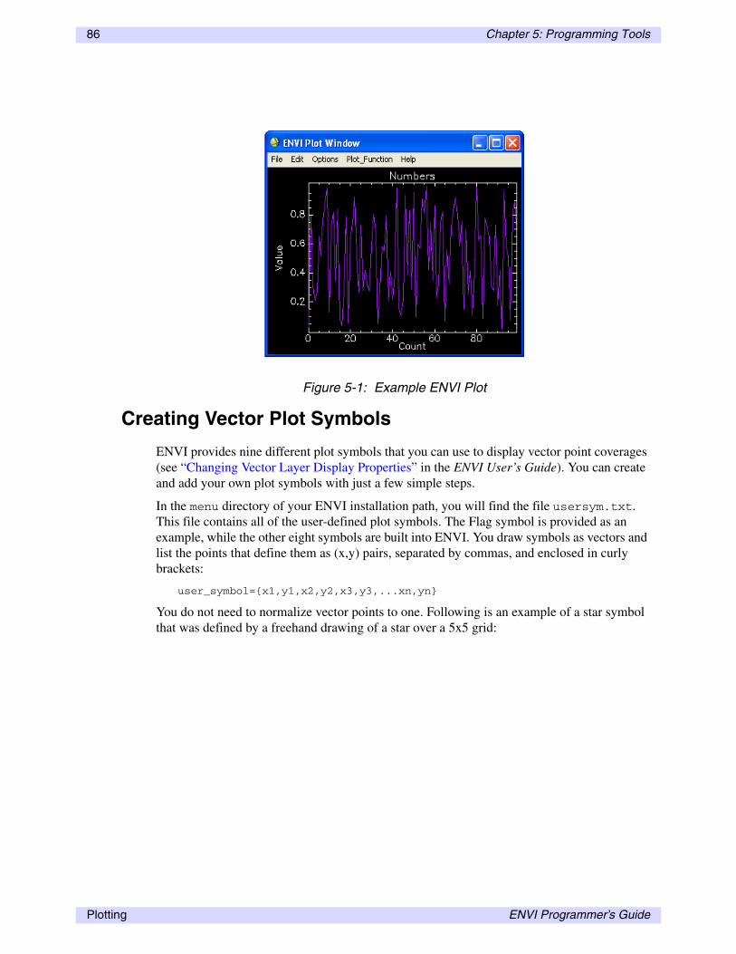
86 Chapter 5: Programming Tools
Creating Vector Plot Symbols
ENVI provides nine different plot symbols that you can use to display vector point coverages (see “Changing Vector Layer Display Properties” in the ENVI User’s Guide). You can create and add your own plot symbols with just a few simple steps.
In the menu directory of your ENVI installation path, you will find the file usersym.txt. This file contains all of the user-defined plot symbols. The Flag symbol is provided as an example, while the other eight symbols are built into ENVI. You draw symbols as vectors and list the points that define them as (x,y) pairs, separated by commas, and enclosed in curly brackets:
user_symbol={x1,y1,x2,y2,x3,y3,...xn,yn}
You do not need to normalize vector points to one. Following is an example of a star symbol that was defined by a freehand drawing of a star over a 5x5 grid:
Figure 5-1: Example ENVI Plot
Plotting ENVI Programmer’s Guide

Chapter 5: Programming Tools 87
star={1.5,0.5,2,2.2,1,3.5,2.2,3,2.5,4.5,2.75,3,4,4,3.25,2.5,3.75,1,2.5, 1.5,1.5,0.5}
The first point is (1.5, 0.5), the second point is (2, 2.2), etc. You can have line breaks at any point on the line that defines the symbol. For example, the following definition for the star also works:
star={
1.5,0.5,2,2.2,1,3.5,2.2,3,2.5,4.5,2.75,3,4,4,3.25,2.5,3.75,1,2.5, 1.5,1.5,0.5}
After you have edited the file usersym.txt, remember to save it and restart ENVI. Your new symbols should appear as options when you edit a vector layer.
Figure 5-2:
ENVI Programmer’s Guide Plotting

88 Chapter 5: Programming Tools
Creating Multipart Vectors
You can create a multipart vector using ENVI’s EVF routines with the PARTS_PTR and TYPE keywords. This section demonstrates how to programmatically create a large polygon that contains three holes.
The example below uses the routines ENVI_EVF_DEFINE_INIT, ENVI_EVF_DEFINE_ADD_RECORD, and ENVI_EVF_DEFINE_CLOSE. Use the PARTS_PTR and TYPE keywords when adding points to the vector record to indicate that the polygon is a multipart polygon. The important step is to specify the main polygon points first, followed by the points for the internal holes. The PARTS_PTR keyword tells ENVI how to order them in the file.
The example polygon has 33 points, with 3 internal holes. The first 7 points define the main polygon, the next 10 define the first hole, the next 8 define the second hole, and the last 7 define the third hole.
Define the PARTS_PTR keyword as follows:
parts_ptr = [0L, 7, -17, -25, -32]
Where the negative sign denotes nodes that are multipart. Set TYPE=5 when defining multipart polygon records.
Example
pro create_multipart_vector ; Create a projection for the points ;the points in this example are in UTM easting/northingproj = envi_proj_create(/utm, zone=13) ; ; define a polygon in easting/northing coordinates ; note first and last coords are identical for each polygon ; first 7 nodes are main polygon, next 10 are first donut, ; next 8 are second donut, last 7 are third donutpolygon = [ $ 276165.00, 4903605.0, $ 276825.00, 4896075.0, $ 276855.00, 4896075.0, $ 283815.00, 4896675.0, $ 284205.00, 4905135.0, $ 276195.00, 4903635.0, $ 276165.00, 4903605.0, $ 278685.00, 4900035.0, $ 278715.00, 4900035.0, $ 278715.00, 4900155.0, $ 278745.00, 4900155.0, $ 279345.00, 4900065.0, $ 279345.00, 4899705.0, $ 279345.00, 4899675.0, $ 279075.00, 4899405.0, $ 278775.00, 4899465.0, $ 278685.00, 4900035.0, $ 281685.00, 4898115.0, $ 281895.00, 4898145.0, $
Creating Multipart Vectors ENVI Programmer’s Guide

Chapter 5: Programming Tools 89
282855.00, 4897965.0, $ 282675.00, 4897365.0, $ 282045.00, 4897035.0, $ 281775.00, 4897395.0, $ 281775.00, 4897425.0, $ 281685.00, 4898115.0, $ 281595.00, 4903395.0, $ 281805.00, 4903395.0, $ 282825.00, 4903395.0, $ 282855.00, 4902645.0, $ 282855.00, 4902585.0, $ 282075.00, 4902075.0, $ 281595.00, 4903395.0]
polygon = reform(polygon, 2, 32) ; Initialize the new EVF file evf_ptr = envi_evf_define_init(‘sample.evf’, $ projection=proj, $ layer_name=’Sample EVF File’) if (ptr_valid(evf_ptr) eq 0) then return
; define parts_ptr as first: main polygon nodes (0-7),; then first hole (next 10 points specified as negative); second hole (next 8 points specified as negative); third hole (last 7 points specified as negative) parts_ptr = [0L, 7, -17, -25, -32]
;add polygon and parts to record - multipart is type 5envi_evf_define_add_record, evf_ptr, polygon, parts_ptr=parts_ptr, type=5
; Finish defining the new EVF file and closeevf_id = envi_evf_define_close(evf_ptr, /return_id) envi_evf_close, evf_id end
ENVI Programmer’s Guide Creating Multipart Vectors

90 Chapter 5: Programming Tools
Reports
You can programmatically access the ENVI report widget, which is used to display text data. The report widget generated by the routine ENVI_INFO_WID displays each element of a user-defined string array on a new line. Once displayed, ENVI automatically manages the resulting report, providing the functionality common to all report widgets, including output to a file. The following example details the use of ENVI_INFO_WID.
Example: Creating a Report
This example interactively creates a text report and displays the result. A string array with four elements, including one NULL string, is created as output to the report widget. The NULL string element translates into a blank line.
1. Start ENVI.
2. Open the IDL development environment (PC) or the shell window where ENVI was started (UNIX, Mac OS X).
3. Type the following at the ENVI command line to create the Report dialog:
str = ['Line 1', 'Next line is blank', '', 'Line 4']ENVI_INFO_WID, str, title='Report'
The following report displays on the screen.
Figure 5-3: Example ENVI Report
Reports ENVI Programmer’s Guide
Chapter 5: Programming Tools 91
RGB Color Triplets
ENVI maintains a set of graphics colors that are used for annotations, vector overlays, plots, classification images, and other items. Many routines reference colors by the graphics color index; however, some use the RGB color triplet. The routine ENVI_GET_RGB_TRIPLETS returns the RGB value for any color index. To avoid indexing past the number of graphics colors, the modulo operator is automatically applied within ENVI_GET_RGB_TRIPLETS. For example, to set the lookup table for a classification image, ENVI_GET_RGB_TRIPLETS is called for each class with the index set equal to the class number. If there are more classes than color indices, the class colors are repeated as necessary.
NoteYou can add custom graphics colors to ENVI by modifying the colors.txt file. (See “Editing System Color Tables” in ENVI Help.) Each line of the file contains an RGB triplet value and a name. Although not required, it is best to leave color 0 as black and 1 as white.
Example: Getting RGB Color Values
This example interactively gets RGB color triplets associated with a graphics color and prints the result to the IDL log window.
1. Start ENVI.
2. Open the IDL development environment (PC) or the shell window where ENVI was started (UNIX, Mac OS X).
3. Type the following at the ENVI command line to get the RGB for color index 0:
ENVI_GET_RGB_TRIPLETS, 0, r, g, bprint, r, g, b
4. Type the following at the ENVI command line to get the RGB for color index 1:
ENVI_GET_RGB_TRIPLETS, 1, r, g, bprint, r, g, b
ENVI Programmer’s Guide RGB Color Triplets

92 Chapter 5: Programming Tools
File Information
Extracting file information is an integral part of ENVI programming. The ENVI_FILE_QUERY routine provides all known basic file information for any open file, whether in memory or on disk, including the dimensions of the data, map coordinates, or any other information you request.
Example: Basic Image Information
This example shows how to interactively choose a file, extract basic file information, and print the result to the IDL log window.
1. Start ENVI.
2. Open any image file.
3. Open the IDL development environment (PC) or the shell window where ENVI was started (UNIX, Mac OS X).
4. Type the following at the ENVI command line to select an input file:
ENVI_SELECT, title='Input Filename', fid=fid
5. Type the following at the ENVI command line to get basic file information and print the result:
ENVI_FILE_QUERY, fid, ns=ns, nl=nl, nb=nb,offset=offset,$ data_type=data_type, interleave=interleaveprint, ns, nl, nb, offset, data_type, interleave
Example: Map Information
This example shows how to interactively choose a file, extract the map projection information, and print the results to the IDL log window. You must choose a georeferenced file using ENVI_SELECT to see associated projection information. ENVI_GET_MAP_INFO returns map information, and ENVI_GET_PROJECTION returns projection information.
1. Start ENVI.
2. Open the IDL development environment (PC) or the shell window where ENVI was started (UNIX, Mac OS X).
3. Open a georeferenced image file. Type the following at the ENVI command line to select an input file:
ENVI_SELECT, title='Georeferenced Filename', fid= fid
4. Type the following at the ENVI command line to get the map information and print the result:
map_info = ENVI_GET_MAP_INFO(fid=fid)print, map_info
5. Type the following at the ENVI command line to get projection information and print the result:
proj = ENVI_GET_PROJECTION(fid=fid)
File Information ENVI Programmer’s Guide

Chapter 5: Programming Tools 93
print, proj
ENVI Programmer’s Guide File Information

94 Chapter 5: Programming Tools
Managing Files
ENVI provides tools to open, close, and select image files both for interactive and batch mode programming. Interactive programs select ENVI image files using the routine ENVI_SELECT, which uses the returned FID as a reference to the file. Image files used for display and processing must be referenced by their FID. When selecting non-image files, such as ROI files, use ENVI_PICKFILE to get the filename. This provides the link to extract the necessary information.
When performing batch mode programming, the routine ENVI_OPEN_FILE opens an ENVI image file and returns the FID without any user interaction. Both batch and interactive programming can use ENVI_FILE_MNG to close and optionally delete image files. See “Examples of ENVI Batch Mode Routines” on page 40.
ENVI_PICKFILE
This routine produces a widget that prompts you to choose a file on disk. ENVI_PICKFILE produces the same widget as selecting File → Open Image File from the ENVI main menu bar. This routine does not actually open a file; instead, it returns the fully qualified file path as a string. It is often used when you know a user will open a new file from disk, or when you do not intend to use ENVI routines to process the file (for example, when you just need to get the name of the file). See ENVI_PICKFILE in the ENVI Reference Guide for a full list of keywords and example usage.
Figure 5-4: ENVI Filename Selection Widget
Managing Files ENVI Programmer’s Guide

Chapter 5: Programming Tools 95
ENVI_SELECT
This routine produces a widget that prompts you to select a file from those that have already been opened. ENVI_SELECT produces ENVI’s file selection dialog, including buttons for spatial and spectral subsetting and for choosing a mask band. This routine also incorporates the functionality of ENVI_PICKFILE because the widget includes a button to open ENVI-format files from disk. ENVI_SELECT not only returns an FID for the selected file, but also the DIMS and POS variables that will likely be required for further processing. See “ENVI_SELECT” in the ENVI Reference Guide for a full list of keywords and example usage.
ENVI_OPEN_FILE
This routine returns an FID with user interaction. It is the most direct, simple way to open an ENVI file. The keyword NO_REALIZE prevents the Available Bands List dialog window from opening when the file is open. If the Available Bands List is already open, this keyword has no effect. See “ENVI_OPEN_FILE” in the ENVI Reference Guide for a full list of keywords and example usage.
ENVI can read a wide variety of formats. ENVI_OPEN_FILE only opens files for which there is an accompanying ENVI header file. The ENVI library contains a special processing routine called ENVI_OPEN_DATA_FILE that opens and returns an FID for
Figure 5-5: Input Selection by File Widget
ENVI Programmer’s Guide Managing Files

96 Chapter 5: Programming Tools
external format files. This routine has a keyword for each type of external file format that ENVI can read, and it requires no user interaction.
ENVI_FILE_MNG
This routine allows you to close or delete opened files from disk. No user interaction is required. See “ENVI_FILE_MNG” in the ENVI Reference Guide for a full list of keywords.
ENVI_GET_FILE_IDS
This routine returns FIDs for all of the currently opened files. See “ENVI_GET_FILE_IDS” in the ENVI Reference Guide for a full list of keywords and example usage.
Example: Choosing Files Interactively
This example demonstrates how to interactively select a file using ENVI_SELECT and close the file with ENVI_FILE_MNG using the returned FID. Once the file selection dialog appears (following Step 3 below), select an open file, or select Open Image File if no files are currently open. Click OK.
If you select Cancel on the file selection dialog, the keyword FID returns a value of 1, indicating that you did not select a file.
1. Start ENVI.
2. Open the IDL development environment (PC) or the shell window where ENVI was started (UNIX, Mac OS X).
3. Type the following at the ENVI command line to select an input file:
ENVI_SELECT, title='Input Filename', fid=fid
4. Type the following at the ENVI command line to close the file:
ENVI_FILE_MNG, id=fid, /remove
Managing Files ENVI Programmer’s Guide

Chapter 5: Programming Tools 97
Accessing Image Data
When image files are very large (as is often the case with remotely sensed images), it is not advisable to read an entire file into memory all at once using IDL’s READU procedure. Instead, ENVI provides two processing routines that read image data in smaller, more manageable pieces. The two routines provide data in a logical organization, either one band at a time, or one spectral slice at a time.
ENVI_GET_DATA
This function is designed to retrieve spatial image data. It returns data from only one specified band at a time. If spatial data are required from more than one band, the band must be called multiple times. The returned dimensions are controlled by the DIMS keyword. See “ENVI_GET_DATA” in the ENVI Reference Guide for a list of keywords and example usage.
ENVI_GET_SLICE
This function is designed to retrieve spectral image data. It returns data from all of the image bands for one specified line, for any number of samples in that line. The data can be returned in either BIP or BIL storage order. See “ENVI_GET_SLICE” in the ENVI Reference Guide for a list of keywords and example usage.
ENVI Programmer’s Guide Accessing Image Data
98 Chapter 5: Programming Tools
Creating ENVI Format Files
ENVI’s image format is perhaps the simplest format possible. See ENVI Image Files in Getting Started with ENVI for more information about ENVI image and header formats.
Saving Image Data to Memory
When a user function results in image data contained in an IDL array, you can readily enter these data into ENVI as a memory-only item.
ENVI_ENTER_DATA
Use this routine to enter image data from an IDL array into the Available Bands List. This routine automatically creates an ENVI header file for the image (which is also stored in memory), and it returns the FID for the in-memory image. Once the image appears in the Available Bands List, you can use it like any other ENVI image and even save it to disk by selecting File → Save File As → ENVI Standard from the ENVI main menu bar. See “ENVI_ENTER_DATA” in the ENVI Reference Guide for a full list of keywords and example usage.
Saving Image Data to Disk
Because IDL’s WRITEU procedure produces ENVI format files, ENVI does not provide a separate library routine for writing image data contained in IDL arrays to disk. Instead, just use WRITEU:
OpenW, unit, 'new_envi_image_file.img', /Get_LUNWriteU, unit, image_arrayFree_LUN, unit
ENVI_SETUP_HEAD
Use this routine to write the ENVI header file for an image that is already saved to disk. The OPEN keyword to this routine also allows you to open the image file into the Available Bands List. If you call ENVI_SETUP_HEAD without setting the OPEN or WRITE keywords, the ENVI header file will be created in memory only (which allows ENVI_FILE_QUERY to read the file’s header information throughout the rest of the user function). ENVI_SETUP_HEAD optionally returns an FID for the image file on disk. See “ENVI_SETUP_HEAD” in the ENVI Reference Guide for a full list of keywords and example usage.
Creating New Files from Existing ENVI Files
A third ENVI routine creates new ENVI-format image and header files, although it can only be used with files that are already open in ENVI (files for which an FID has already been obtained).
Creating ENVI Format Files ENVI Programmer’s Guide

Chapter 5: Programming Tools 99
CF_DOIT
Use this routine to create a new ENVI-format file from existing ENVI files. The images that are incorporated into the new file can be any combination of open ENVI files on disk or in memory, and you can save the resulting file to disk or memory. CF_DOIT is equivalent to selecting File → Save File As → ENVI Standard from the ENVI main menu bar. See “CF_DOIT” in the ENVI Reference Guide for a full list of keywords and example usage.
ENVI Programmer’s Guide Creating ENVI Format Files

100 Chapter 5: Programming Tools
Creating ENVI Format Files ENVI Programmer’s Guide

Chapter 6
Working with Interactive User Routines
This chapter covers the following topics:
Overview of Interactive User Routines . . . . . . 102Plot Functions . . . . . . . . . . . . . . . . . . . . . . . . . 103Spectral Analyst Functions . . . . . . . . . . . . . . . 105
User-Defined Map Projection Types . . . . . . . . 108User-Defined RPC Reader . . . . . . . . . . . . . . . . 111User Move Routines . . . . . . . . . . . . . . . . . . . . 115
ENVI Programmer’s Guide 101

102 Chapter 6: Working with Interactive User Routines
Overview of Interactive User Routines
This chapter covers the development of user functions that relate to ENVI’s interactive analysis. For selected functions, ENVI allows you to develop additional methods or transforms that are applied automatically to the data. Interactive user functions are triggered by certain events or user selection. For example, when you select a custom plot function, it applies a transformation to the plot data and displays the result in place of the original data. You can also apply custom scoring functions to ENVI’s Spectral Analyst and attach a user function to the zoom event. Detailed descriptions and examples are provided in the following sections.
Overview of Interactive User Routines ENVI Programmer’s Guide

Chapter 6: Working with Interactive User Routines 103
Plot Functions
Plot functions provide a method for applying transforms or routines to data in any ENVI Plot Window. ENVI provides a standard set of plot functions while also allowing you to define custom plot functions, which receive the normal plot data as input, apply the processing, and return the transformed data to the plot. Any new data are also applied through the selected plot function. Plot functions only operate on the y-axis data; the x-axis remains the same. Plot functions are typically applied to spectral data from Z Profiles, spectral libraries, ROI means, or other sources. However, there are no data source requirements to these routines. Refer to “Using Interactive Plot Functions” in the ENVI User’s Guide for additional information.
You can add custom plot functions to ENVI by entering the menu name and function into the useradd.txt file in the menu directory of the installation. Plot functions use the {plot} tag to differentiate them from other functions. The format for a plot function is:
{plot} {Button Name} {function_name} {type=n}
Where:
• {plot}: Tag that indicates the following definition is a plot function
• {Button Name}: Menu button name for the Plot_Function menu
• {function_name}: Name of the plot function to call
• {type=n}: Type of plot function updates. Set {type=0} to call the plot function only when new data are available. Set {type=1} to call the plot function when new data are available or the plot is zoomed.
Following is a sample portion of the useradd.txt file related to plot functions:
{plot} {Normal} {sp_normal} {type=0}{plot} {Continuum Removed} {sp_continuum_removed} {type=1}{plot} {Binary Encoding} {sp_binary_encoding} {type=0}
Plot function declarations have a number of arguments, including the x-axis and y-axis data, bad band information, and left and right zoom indices. Remember, ENVI calls your plot function and automatically passes the required parameters to it. A sample plot function declaration is shown below:
FUNCTION my_func, x, y, bbl, bbl_array, l_pos=l_pos, $ r_pos=r_pos, _extra=_extra
Where:
• my_func: The plot function name
• x: Data values for the x-axis
• y: Data values for the y-axis
• bbl: Pointer to each of the bad bands in a Z Profile. If there are no bad bands or the current plot is not a Z Profile, this value is undefined.
• bbl_array: An array of ones and zeros representing the good and bad points in the plot, respectively. The number of elements of bbl_array equals the number of elements of x. This array is defined for all plots, regardless of the type of data.
• l_pos: The left (lower) index of the x array
ENVI Programmer’s Guide Plot Functions
104 Chapter 6: Working with Interactive User Routines
• r_pos: The right (upper) index of the x array
• _extra: You must specify this keyword to collect all extra keywords that ENVI uses when calling the user-defined function.
The plot function returns the new y-axis data.
You can use the following model for plot functions:
FUNCTION my_plot_func, x, y, bbl, bbl_array, $ l_pos=lpos, r_pos=r_pos, _extra=_extra statements ... RETURN, plot_resultEND
Plot functions that operate on Z Profile data may be concerned with the bad bands information passed to the function. Bad bands are typically ignored while calculating the plot function, and their output values are not displayed in the plot. To ignore bad bands, define a pointer to the good bands and use it as an index into the x and y arrays. The following statement sets the variable PTR to an index of all good points, and the variable COUNT equals the number of good points.
ptr = where(bbl_array EQ 1, COUNT)
Example: Plot Function
This example creates a plot function to compute the zero-mean value of a plot (in other words, to center the plot). Calculate the mean value only on the good points in the plot; the mean does not change when the plot is zoomed. First, find the good data points by examining BBL_ARRAY and build an index where it is equal to 1. Next, use only the good points to calculate the mean, which is subtracted from the y-axis data. If no valid data points exist, then set the result to 0. The resulting y-axis data are returned from the function.
The following sample code is also available in the file irplot.pro in the lib directory of the ENVI installation.
function pf_zero_mean, x, y, bbl, bbl_array, _extra=_extra bbl_ptr = where(bbl_array eq 1, count) if (count gt 0) then $ result = y - (total(y[bbl_ptr]) / count) $ else $ result = fltarr(n_elements(y)) return, resultend
The following steps outline the procedure for executing this example:
1. Save the plot function to a file and place it in the save_add directory.
2. Add the following plot function definition to the useradd.txt file in the menu directory of the installation tree. This allows you to select the function from the Plot_Function menu.
{plot} {Zero Mean} {pf_zero_mean} {type=0}
3. Start ENVI.
4. Open a file and display an X Profile.
5. Select Zero Mean from the Plot_Function menu in the X Profile plot.
Plot Functions ENVI Programmer’s Guide

Chapter 6: Working with Interactive User Routines 105
Spectral Analyst Functions
Spectral Analyst functions provide a method to match an unknown spectrum to the materials in a spectral library. ENVI includes common spectral similarity techniques such as Binary Encoding, Spectral Angle Mapper, and Spectral Feature Fitting. You can add custom functions to the Spectral Analyst and use them along with ENVI-defined functions. Individual 0 to 1 scores are accumulated for each of the functions, and the library spectra are ranked in order of best-to-worst match.
Add custom spectral analyst functions to ENVI by entering the menu name and function into the useradd.txt file in the menu directory of the installation. Spectral Analyst functions use the {identify} tag to differentiate them from other functions in this file. The format for an entry is:
{identify} {Method Name} {Out Name} {func_name} {min, max}
Where:
• {identify}: Tag to indicate the following definition is a Spectral Analyst function
• {Method Name}: Method name for the spectral identification widget
• {Out Name}: Column name for the Spectral Analyst output ranking report window
• {func_name}: Name of the spectral identification function to call. The function name is also used as the base name for FUNCTION_NAME_SETUP, called once for a given spectral library.
• {min, max}: The default minimum and maximum outputs for the identification function. You may edit the default minimum and maximum values when running the Spectral Analyst function. The current scale factors are passed into the identification function. The output values are then scaled to a [0, 1] range to allow a cumulative ranking of all methods.
Spectral Analyst functions have two parts. The first is the setup procedure, which is called after the spectral library is selected. It conditions the library for the selected identification function. All library calculations that are not dependent on the input data should be performed once in the setup procedure. The name of the setup procedure is formed from the function name with an additional “_SETUP”. For example, the setup procedure for FUNC_NAME is FUNC_NAME_SETUP.
NoteUnlike the identification function, the setup procedure is a procedure that you must define even if no setup is necessary.
The setup procedure for the function FUNC_NAME is declared as follows:
PRO func_name_setup, wl, spec_lib, handles, num_spec=num_spec
Where:
• wl: Wavelength values for the spectral library. All spectra in the library have one sample at each wavelength, allowing a single wavelength vector for each library.
ENVI Programmer’s Guide Spectral Analyst Functions

106 Chapter 6: Working with Interactive User Routines
• spec_lib: A 2D array of all spectral library spectra. The dimensions are [wavelength_samples, num_spectra].
• handles: An array of two handles for storing user data. Any preprocessing of the spectral library should be stored in one of these handles. The handle array is also passed into the identification function.
• num_spec: The number of spectra in the library. This value is equal to the second dimension of the SPEC_LIB array.
The second part of the Spectral Analyst user function is the identification function, which calculates the score for the current spectrum against the library spectra. The method for calculating the score depends on the user function. You must apply the current minimum and maximum scale factors to the resulting score. The function output is an array of scaled scores for each of the library spectra. The identification function for FUNC_NAME is declared as follows:
FUNCTION func_name, wl, ref_spec, spec_lib, handles,$ num_spec=num_spec, scale_vals=scale_vals
Where:
• wl: Wavelength values for the spectral library. All spectra in the library have one sample at each wavelength, allowing a single wavelength vector for each library.
• ref_spec: Reference spectrum used to score against the library. The reference spectrum has the same number of wavelength samples as the library spectra.
• spec_lib: A 2D array of all spectral library spectra. The dimensions are [wavelength_samples, num_spectra].
• handles: An array of two handles for storing user data. Any data stored in the setup procedure can be extracted using HANDLE_VALUE.
• num_spec: The number of spectra in the library. This value is equal to the second dimension of the SPEC_LIB array.
• scale_vals: An array containing the current minimum and maximum scale factors, respectively. The scale factors are applied to the calculated score to bring its range to 0 to 1.
The resulting score is automatically combined with other spectral analyst functions based on the current weights. Any spectral analyst function with a weight of 0 is not called since its output score would not be used.
Example: Spectral Analyst Function
This example creates a Spectral Analyst function that calculates the minimum distance between each library spectra and the current reference spectrum. The setup procedure is defined, but it is empty since no setup is necessary in this example. The identification function computes the distance measure as the square root of the sum of the differences at each wavelength. A distance score is computed between each library spectrum and the input reference spectrum. The output scores are scaled by the largest distance error in order to keep the distance measure between 0 and 1.
Spectral Analyst Functions ENVI Programmer’s Guide

Chapter 6: Working with Interactive User Routines 107
NoteThis example is for illustration purposes only. An actual minimum distance Spectral Analyst function removes the continuum from the library (in the setup procedure) and reference spectrum prior to calculating the distance score.
The following sample code is also available in the file irsadist.pro in the lib directory of the installation:
pro irsadist_func_setup, wl, spec_lib, handles, num_spec=num_spec ; No initialization is necessaryend
function irsadist_func, wl, ref, spec_lib, handles, num_spec=num_spec,$ scale_vals=scale_vals ; Compute the distance compared to each library member result = dblarr(num_spec) for i=0L, num_spec-1 do $ result[i] = sqrt(total((spec_lib[*,i]-ref)^2, /double))
; scale the result from zero to one dmax = max(result, min=dmin) return, (1d - ((result - dmin) / (dmax - dmin))) / scale_vals(1)end
The following steps outline the procedure for executing this example.
1. Save the function to a file and place it in the save_add directory.
2. Add the Spectral Analyst function definition to the useradd.txt file in the menu directory of the installation tree so you can select the function from the Spectral Analyst menu.
{identify} {Minimum Distance} {MDIST} {irsadist_func} {0,1.}
3. Start ENVI.
4. Open a file and display a Z Profile.
5. Select Spectral Analyst from the Spectral Tools menu and open a spectral library for comparison.
6. Set the Minimum Distance weight to 1.0 and select OK.
7. Rank the current Z Profile by selecting Apply.
ENVI Programmer’s Guide Spectral Analyst Functions

108 Chapter 6: Working with Interactive User Routines
User-Defined Map Projection Types
ENVI supports many different map projections and map projection types. You can create custom map projections by selecting Map → Customize Map Projections from the ENVI main menu bar. (See “Building Customized Map Projections” in the ENVI User’s Guide.) However, you may want to define your own map projection type. Add these to ENVI by writing an IDL procedure that calculates the forward and inverse conversions between latitude/longitude and the new projection coordinates. For information about ENVI’s datums, ellipsoids, and map projections, see “Map Tools” in the ENVI User’s Guide.
Add custom map projection types to ENVI by entering the projection name and user routine name in the useradd.txt file in the menu directory of the installation. Map projection types use the {projection type} tag to differentiate them from other routines in this file. The format for an entry is as follows:
{projection type} {projection name} {routine_root_name} {number of extra parameters}
Where:
• {projection type}: Tag to indicate the following definition is a user-defined projection type
• {projection name}: Name of the projection in the Projection Type list
• {routine_root_name}: Root name for the user routine
• {number of extra parameters}: Number of parameters this projection requires in addition to the default parameters: ellipsoid a and b, projection origin (latitude/longitude), and false easting/northing. This value can be 0 if there are no additional parameters needed. You can add a maximum of nine additional parameters.
User-defined map projection routines may have two parts: one that allows you to enter extra parameters, and another that performs the coordinate conversions. If extra parameters are needed, then use a procedure named routine_root_name_DEFINE to input these parameters. This procedure contains one parameter that is an array of the number of extra parameters needed. These are double-precision, floating-point data values, and you can input up to nine of them. This procedure assigns the values to the extra parameters by either getting input from a dialog when the Build Customized Map Projection function runs, or by setting the values in the function. If the number of extra parameters is 0, then routine_root_name_DEFINE is not needed.
The second required procedure is named routine_root_name_CONVERT. It performs the forward and inverse conversions between latitude/longitude and new projection coordinates. This procedure must work for both a scalar value or an array of values, and it has six parameters, as shown below:
routine_root_name_convert, x, y, lat, lon, to_map=to_map, projection=proj
Where:
• x, y: Map projection coordinates
• lat/lon: Latitude and longitude coordinates
• to_map: If set, the procedure converts latitude/longitude to map x,y coordinates. If not set, the procedure converts the other way around.
User-Defined Map Projection Types ENVI Programmer’s Guide

Chapter 6: Working with Interactive User Routines 109
• proj: User-defined projection
Add the .pro or .sav file for the user routine to the save_add directory of the ENVI installation.
To complete the projection definition process:
1. Restart ENVI.
2. From the ENVI main menu bar, select Map → Customize Map Projections.
3. The newly defined projection type will appear in the Projection Type list.
4. Select the projection type and enter the values for the parameters.
The routine saves the new projection to the map_proj.txt file, and you can select it from among all ENVI projection routines.
Example: User-Defined Map Projection
The following two examples of user-defined map projections (USER_PROJ_TEST1 and USER_PROJ_TEST2) illustrate how to define a new projection without any additional parameters and with four additional parameters, respectively. Depending on the type of projection you add, use one of the two examples as a model.
For the sake of illustration, the first test passes through the map coordinates by setting the output map coordinates equal to the input coordinates. Since there are no additional parameters, only the _CONVERT routine is needed.
pro user_proj_test1_convert, x, y, lat, lon, to_map=to_map, projection=p if (keyword_set(to_map)) then begin x = lon y = lat endif else begin lon = x lat = y endelseend
The following steps outline the process for executing this example:
1. Save the routine to a file and place it in the save_add directory.
2. Add the user-defined projection definition to the useradd.txt file in the menu directory of the installation tree to show the new user-defined projection.
{projection type} {User Projection #1} {user_proj_test1} {0}
3. Start ENVI.
4. Define your new projection. From the ENVI main menu bar, select Map → Customize Map Projections.
5. Select your new projection type name from the Projection Type list.
6. After successfully entering any parameters, you can save your new projection to map_proj.txt.
ENVI Programmer’s Guide User-Defined Map Projection Types

110 Chapter 6: Working with Interactive User Routines
The next example requires you to define four additional parameters, which means you must create both the _DEFINE and _CONVERT routines.
pro user_proj_test2_define, add_params if (n_elements(add_params) gt 0) then begin default_1 = add_params[0] default_2 = add_params[1] default_3 = add_params[2] default_4 = add_params[3] endif
base = widget_auto_base(title='User Projection #1 Additional Parameters') sb = widget_base(base, /column, /frame) sb1 = widget_base(sb, /row) wp = widget_param(sb1, prompt='Parameter #1', xsize=12, dt=4,$ field=4, default=default_1, uvalue='param_1', /auto) sb1 = widget_base(sb, /row) wp = widget_param(sb1, prompt='Parameter #2', xsize=12, dt=4,$ field=4, default=default_2, uvalue='param_2', /auto) sb1 = widget_base(sb, /row) wp = widget_param(sb1, prompt='Parameter #3', xsize=12, dt=4,$ field=4, default=default_3, uvalue='param_3', /auto) sb1 = widget_base(sb, /row) wp = widget_param(sb1, prompt='Parameter #4', xsize=12, dt=4,$ field=4, default=default_4, uvalue='param_4', /auto) result = auto_wid_mng(base) if (result.accept) then $ add_params = [result.param_1, result.param_2, $ result.param_3, result.param_4]end
pro user_proj_test2_convert, x, y, lat, lon, to_map=to_map, projection=pif (keyword_set(to_map)) then begin x = lon * 100. + p.params[4] y = lat * 100. + p.params[5] endif else begin lon = (x - p.params[4]) / 100. lat = (y - p.params[5]) / 100. endelseend
The following steps outline the procedure for executing this example.
1. Save the routine to a file and place in the save_add directory.
2. Add the user-defined projection definition to the useradd.txt file in the menu directory of the installation tree to show the new user-defined projection.
{projection type} {User Projection #2} {user_proj_test2} {4}
3. Start ENVI.
4. Define your new projection. From the ENVI main menu bar, select Map → Customize Map Projections.
5. Select your new projection type name from the Projection Type list.
6. After successfully entering any parameters, you can save your new projection to map_proj.txt.
User-Defined Map Projection Types ENVI Programmer’s Guide

Chapter 6: Working with Interactive User Routines 111
User-Defined RPC Reader
From the ENVI main menu bar, selecting Map → Orthorectification → Generic RPC and RSM allows you to access a user function for reading a custom rational polynomial coefficients (RPC) file format. You cannot create a user-defined RPC reader based on replacement sensor model (RSM) information.
Place the user function in the save_add directory of the ENVI installation to compile when an ENVI session starts. It is associated to the Generic RPC and RSM option through the useradd.txt file in the menu directory of the ENVI installation.
You should implement this RPC reader function to exit gracefully if the input file does not contain RPCs. It must also never display any user-interface elements, which interfere with ENVI's ability to read RPC data from other files. Once implemented, you must register the RPC reader function with ENVI so it is called when ENVI attempts to import RPC data.
This function must also find the coefficients for the specified image or file, copy them to an ENVI RPC structure, and return this structure to ENVI. If the RPCs cannot be found or imported, the routine should not produce an error, but return a value of –1, which indicates your function could not import any RPCs for these data.
The inputs to the RPC reader function can be either a file ID identifying an image or a filename. Specify the file ID using the FID keyword, and specify the filename with the FNAME keyword. ENVI can call your RPC reader function with either the FID or FNAME keyword set, but not both.
If the input from ENVI is an file ID, it indicates the RPC information should come from an image already opened in ENVI. The file ID is used to identify the open image associated with the requested RPCs. The RPC information should be imported for this file and then returned to ENVI in the RPC coefficient structure. If no RPC information can be read for this file, a value of –1 must be returned to ENVI.
If none of the RPC readers available to ENVI (including any user-defined RPC reader functions) can import RPC information from the file ID, you are prompted to select the file containing RPC coefficients. This filename is then passed to each reader in an attempt to import RPC information from the file. If you select a file containing RPC information, this file is passed to the RPC reader function with the FNAME keyword. As with the file ID, it is your responsibility to read the RPC information from this file, and return the data in an RPC structure or return a value of –1 if no RPC information could be imported.
The RPC data returned to ENVI must be stored in an ENVI_RPC_STRUCT structure, which is defined by ENVI to contain the coefficients required to perform the RPC transformation. The tags in this structure are described in Table 6-1.
Tag Name Data Type and Size
Description
OFFSETS Double-precision array[5]
Normalization offset coefficients for computing RPC transformation, in the following order: line, sample, latitude, longitude, height
Table 6-1: ENVI_RPC_STRUCT Structure
ENVI Programmer’s Guide User-Defined RPC Reader

112 Chapter 6: Working with Interactive User Routines
After you have written your RPC reader function, save it as a .pro file (or compile to a .sav file with the same name as your function), and place it in the save_add directory, where it will be automatically compiled when ENVI starts. Modify the useradd.txt file in the menu directory to register your RPC reader function. Add the following line to the useradd.txt file:
{rpc reader} {rpc reader name} {rpc reader function name} {}
The first set of brackets indicates the function will be added as an RPC reader to ENVI. The second set of brackets indicates the name of this new reader (which is not used by ENVI, but allows you to distinguish between multiple RPC readers, if present). The third set of brackets contains the routine name of your RPC reader function. The fourth set of brackets remains
SCALES Double-precision array[5]
Normalization scale coefficients for computing RPC transformation, in the following order: line, sample, latitude, longitude, height
LINE_NUM_COEFF Double-precision array[20]
20 numerator coefficients for the rational polynomial row value calculation
LINE_DEN_COEFF Double-precision array[20]
20 denominator coefficients for the rational polynomial row value calculation
SAMP_NUM_COEFF Double-precision array[20]
20 numerator coefficients for the rational polynomial column value calculation
SAMP_DEN_COEFF Double-precision array[20]
20 denominator coefficients for the rational polynomial column value calculation
P_OFF Double-precision scalar
Column offset (in image coordinates) from the upper-left corner of the RPC source image to the upper-left corner of this image subset, if any. This value is almost always 0, unless the image being read has been spatially subset from a larger source image to which the RPCs apply.
L_OFF Double-precision scalar
Row offset (in image coordinates) from the upper-left corner of the RPC source image to the upper-left corner of this image subset, if any. This value is almost always 0, unless the image being read has been spatially subset from a larger source image to which the RPCs apply.
Tag Name Data Type and Size Description
Table 6-1: ENVI_RPC_STRUCT Structure (Continued)
User-Defined RPC Reader ENVI Programmer’s Guide

Chapter 6: Working with Interactive User Routines 113
empty. After you have modified and saved the useradd.txt file, you can access your custom RPC reader from the ENVI main menu bar by selecting Map → Orthorectification → Generic RPC after you restart ENVI.
Example: User-Defined RPC Reader
The following example RPC reader function reads the coefficients from a standard ASCII text file, with one coefficient per line. In this example, the name of the file containing RPC coefficients must be the same as the name of the input file with an .rpc extension. The RPC reader function uses the name and extension to import the RPCs directly from the file ID for the associated image. The following example code is saved to a file named envi_user_rpc_reader.pro, which is the same name as the function. This file is then placed in the save_add directory.
FUNCTION ENVI_USER_RPC_READER, FID=fileID, FNAME=filename, $ _EXTRA=extraCOMPILE_OPT STRICTARR
; NOTE: You should include error handling in this function.; If no RPCs can be read, return -1.; If read successfully, return a structure full of RPCs.; Make sure you have the filename to read in the; coefficients.IF (N_ELEMENTS(filename) EQ 0) THEN BEGIN IF (N_ELEMENTS(fileID) EQ 0) THEN RETURN, -1 ENVI_FILE_QUERY, fileID, FNAME = filename filename = filename + '.rpc'ENDIF
; Get the RPC structure to fill.rpcCoeffs = get_rpc_coefficient_structure()
; Find the name of the RPC file, then open it to read.; For this example, the RPCs are assumed to be stored in a file; with an .rpc extension appended to the name of the data file.IF (~FILE_TEST(filename)) THEN RETURN, -1OPENR, unit, filename, /GET_LUNvalue = ''
; Fill up the RPC offset values.FOR index = 0, 4 DO BEGIN READF, unit, value rpcCoeffs.offsets[index] = DOUBLE(value)ENDFOR; Fill up the RPC scale values.FOR index = 0, 4 DO BEGIN READF, unit, value rpcCoeffs.scales[index] = DOUBLE(value)ENDFOR; Fill up the RPC numerator coefficients for the line terms.FOR INDEX = 0, 19 DO BEGIN READF, unit, value rpcCoeffs.line_num_coeff[index] = DOUBLE(value)ENDFOR; Fill up the RPC denominator coefficients for the line terms.FOR INDEX = 0, 19 DO BEGIN READF, unit, value
ENVI Programmer’s Guide User-Defined RPC Reader

114 Chapter 6: Working with Interactive User Routines
rpcCoeffs.line_den_coeff[index] = DOUBLE(value)ENDFOR; Fill up the RPC numerator coefficients for the sample terms.FOR INDEX = 0, 19 DO BEGIN READF, unit, value rpcCoeffs.samp_num_coeff[index] = DOUBLE(value)ENDFOR; Fill up the RPC denominator coefficients for the sample terms.FOR INDEX = 0, 19 DO BEGIN READF, unit, value rpcCoeffs.samp_den_coeff[index] = DOUBLE(value)ENDFORREADF,unit,valuerpcCoeffs.p_off = DOUBLE(value)READF,unit,valuerpcCoeffs.l_off = DOUBLE(value); Close the file.FREE_LUN, unit
; Return the RPC coefficients.RETURN, rpcCoeffs
END
After you save the function and place it in the save_add directory, you must register it by adding the following line to the useradd.txt file in the menu directory:
{rpc reader} {example rpc reader} {envi_user_rpc_reader} {}
After restarting your ENVI session, ENVI automatically calls this function if all of the standard ENVI RPC readers fail to find RPCs for the input file when you select Map → Orthorectification → Generic RPC from the ENVI main menu bar.
User-Defined RPC Reader ENVI Programmer’s Guide

Chapter 6: Working with Interactive User Routines 115
User Move Routines
Two types of user move routines provide methods of attaching user functions to motion events: ENVI calls a user-defined move routine each time the zoom location is moved, and a user-defined motion routine each time the cursor moves in the display group. For both move routines, the position information is passed into the routine, allowing the display of position-dependent information. For example, move routines can display housekeeping data for the current line of an image.
Most move routines display user data in a text widget, much like the Cursor Location/Value tool. The move routine first checks if the widget exists, and if not, it creates the widget. Keep in mind that the widget may have been closed since the last update. Displayed data can come from the current image or another source, and you can prompt for an input file when you create a move routine.
Move routines are defined in the ENVI configuration file envi.cfg, or by selecting File → Preferences from the ENVI main menu bar. Once you define a move routine, ENVI calls it for every zoom location event, regardless of the image being displayed. User move routines may also use the file type to further restrict the display of data. When displaying housekeeping data from a custom format, you should add a new file type to the filetype.txt file in the menu directory of the installation tree. The move routine can then use ENVI_FILE_TYPE to check for the proper file type prior to displaying data.
Move routines can also output data directly to the IDL log window using a simple PRINT statement. Although not elegant, this is a simple way to develop or debug move routines that will eventually use a widget interface.
User-Defined Move Routines
User-defined move routines are defined as procedures with parameters for the display number and the x and y locations. The latter are floating-point values, which may be fractional portions of a pixel.
PRO user_move, dn, xloc, yloc, xstart=xstart, ystart=ystart
Where:
• dn: The display number where the zoom event occurred within
• xloc: The current x location in image coordinates. Subtract the xstart value to convert to file coordinates.
• yloc: The current y location in image coordinates. Subtract the ystart value to convert to file coordinates.
• xstart: The x starting location of the first pixel in the file (in image coordinates)
• ystart: The y starting location of the first pixel in the file (in image coordinates)
File coordinates are necessary to use the function ENVI_GET_DATA, but you may not need them for extracting custom housekeeping data.
ENVI Programmer’s Guide User Move Routines

116 Chapter 6: Working with Interactive User Routines
NoteWhen you display bands from different files as an RGB image, you should retrieve the x and y starting location from ENVI_FILE_QUERY instead of using the keyword inputs.
Example: Simple User-Defined Move Routine
This example creates a user-defined move routine that outputs the current zoom position and pixel value to the IDL log window. Using the DN, the routine ENVI_DISP_QUERY returns the FID associated with the displayed band. The COLOR keyword to ENVI_DISP_QUERY is used to determine if a gray scale or RGB is currently displayed. For each displayed band, a DIMS array is created and used as input into ENVI_GET_DATA to retrieve the value of the current pixel. The pixel value is printed to the IDL log window.
This sample code is also available in the file irudm1.pro in the lib directory of the installation.
pro ud_move_1, dn, xloc, yloc, xstart=xstart, ystart=ystart; Get the file FIDs envi_disp_query, dn, fid=fid, pos=pos, color=color if (color eq 8) then nb = 3 $ else nb = 1; Print the DN and zoom location print, dn, xloc + 1, yloc + 1; Print out the current pixel for each displayed band for i=0, nb-1 do begin envi_file_query, fid[i], xstart=xstart, ystart=ystart $ dims = long([0, xloc - xstart, xloc - xstart, $ yloc - ystart, yloc - ystart]) print, envi_get_data(fid=fid[i], pos=pos[i], dims=dims) endforend
The following steps outline the procedure for executing this example.
1. Save the routine to a file and place it in the save_add directory of the ENVI installation.
2. Start ENVI.
3. Select File → Preferences from the ENVI main menu bar and enter ud_move_1 in the User Defined Move Routine field. When prompted, save and overwrite the existing ENVI configuration file.
4. Open a file and display a band.
5. Open the IDL Development Environment (PC) or the shell window where ENVI was started (UNIX, Mac OS X).
6. When you move the zoom location, the move routine prints the data to the IDL Output Log window.
User Move Routines ENVI Programmer’s Guide

Chapter 6: Working with Interactive User Routines 117
Example: Widget User-Defined Move Routine
This example creates a user-defined move routine that outputs the current display number, zoom position, and starting pixel values to a widget. The routine first checks for the text widget used to display the move routine data and, if not found, creates one. The text string is then output to the text widget or display group.
The following sample code is also available in the file irudm2.pro in the lib directory of the installation.
pro ud_move_2, dn, xloc, yloc, xstart=xstart, ystart=ystart common ud_move_2_c, ud_wid, data ; ; Check for a valid widget id. If the widget ID is not valid ; then create the widget, otherwise update the text field. ; if (n_elements(ud_wid) eq 0) then ud_wid = -1L if (widget_info(ud_wid, /valid) eq 0) then begin ; ; Create the widget used to display the data. Give it a title and ; use envi_center to center the widget on the screen. A text widget ; is created as a place holder for the user text data. ; title = 'Custom Move Routine' envi_center, xoff, yoff base = widget_base(title=title, xoff=xoff, yoff=yoff, $ /row, group=envi_main_base()) sb = widget_base(base, /column, /frame) sb1 = widget_base(sb, /col) lab = widget_label(sb1, value='Line Header Data') tw = widget_text(sb1, value='Data display area.', xs=40, ys=5) widget_control,base,/realize ; ; Use the data structure for any info the you would like to ; keep around. ; data = {tw:tw} ud_wid = base
endif ; ; Update the text widget with the current information. ; For now just display the dn, xloc, yloc, xstart, ystart. ; msg = ['Display Number ' + string(dn), 'Loc (x,y): ' + string(xloc+1) $ + ',' + string(yloc+1), 'Start (x,y): ' + string(xstart+1) + ',' + $ string(ystart+1)] widget_control, data.tw, set_value=msg, /no_copyend
The following steps outline the procedure for executing this example.
1. Save the routine to a file and place it in the save_add directory of the ENVI installation.
2. Start ENVI.
ENVI Programmer’s Guide User Move Routines
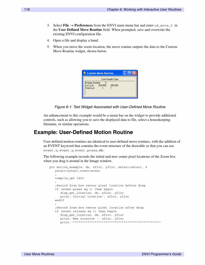
118 Chapter 6: Working with Interactive User Routines
3. Select File → Preferences from the ENVI main menu bar and enter ud_move_2 in the User Defined Move Routine field. When prompted, save and overwrite the existing ENVI configuration file.
4. Open a file and display a band.
5. When you move the zoom location, the move routine outputs the data to the Custom Move Routine widget, shown below.
An enhancement to this example would be a menu bar on the widget to provide additional controls, such as allowing you to save the displayed data to file, select a housekeeping filename, or similar operations.
Example: User-Defined Motion Routine
User-defined motion routines are identical to user-defined move routines, with the addition of an EVENT keyword that contains the event structure of the drawable so that you can use event.x, event.y, event.press, etc.
The following example records the initial and new center pixel locations of the Zoom box when you drag it around in the Image window.
pro motion_example, dn, xfloc, yfloc, xstart=xstart, $ ystart=ystart,event=event ; compile_opt idl2 ; ;Record Zoom box center pixel location before drag if (event.press eq 1) then begin disp_get_location, dn, xfloc, yfloc print,'Initial Location', xfloc, yfloc endif ; ;Record Zoom box center pixel location after drag if (event.release eq 1) then begin disp_get_location, dn, xfloc, yfloc print,'New Location ', xfloc, yfloc print,'************************************************'
Figure 6-1: Text Widget Associated with User-Defined Move Routine
User Move Routines ENVI Programmer’s Guide

Chapter 6: Working with Interactive User Routines 119
endif ; return ;end
The following steps outline the procedure for executing this example.
1. Save the routine to a file and place it in the save_add directory of the ENVI installation.
2. Start ENVI.
3. Select File → Preferences from the ENVI main menu bar and enter motion_example in the User Defined Motion Routine field. When prompted, save and overwrite the existing ENVI configuration file.
4. Open a file and display a band.
5. When you drag the Zoom box around the Image window, the motion routine outputs the data to the IDL log window.
ENVI Programmer’s Guide User Move Routines

120 Chapter 6: Working with Interactive User Routines
User Move Routines ENVI Programmer’s Guide

Chapter 7
Creating Custom File Input
This chapter covers topics about creating custom file input. It includes the following:
Types of Image Storage . . . . . . . . . . . . . . . . . . 122Parsing Image File Headers . . . . . . . . . . . . . . . 123Custom File Readers . . . . . . . . . . . . . . . . . . . . 125
Spatial Read Routines . . . . . . . . . . . . . . . . . . . 126Spectral Read Routines . . . . . . . . . . . . . . . . . . 128
ENVI Programmer’s Guide 121

122 Chapter 7: Creating Custom File Input
Types of Image Storage
ENVI provides a very powerful interface for importing files not directly supported. In fact, you can interactively open many files in ENVI by specifying the number of samples, lines, bands, data type, header offset, and data storage interleave. The data in these files must be stored as BSQ, BIL, or BIP. A more automated approach, and the only custom development needed, is to parse the header for the necessary parameters and use ENVI_SETUP_HEAD to open the file. Once the file is open, ENVI handles the remainder of the I/O.
When the files do not conform to any of the standard storage formats, you can still integrate the data without conversion. By creating a spatial and spectral read routine, the data quickly become integrated into ENVI. As the name implies, the spatial read routine handles all spatial data requests, from the whole image to a single pixel. The spectral read routine is responsible for all spectral requests. ENVI breaks down all input data requests into these two fundamental types, allowing easy integration of custom read routines.
Methods of importing files into ENVI are covered in more detail in the following sections.
Types of Image Storage ENVI Programmer’s Guide

Chapter 7: Creating Custom File Input 123
Parsing Image File Headers
To automatically import files that are currently not supported, you must develop a parsing routine to extract the basic file information. If the data are not stored as BSQ, BIL, or BIP, you must also develop a custom read routine (see “Custom File Readers” on page 125). At a minimum, you must specify the following information in order to open a file in ENVI.
• Number of samples, lines, and bands• Data type• Offset to image data• File storage order: BSQ, BIL, or BIP• Byte storage order: Host (Intel), Network (IEEE)
You can parse additional file information from the header, including any georeferencing information. Open the file using ENVI_SETUP_HEAD with the keywords set from the parsed header information. Set the OPEN keyword to open the file, and optionally, the WRITE keyword to write an ENVI header file.
The strategy for parsing the header depends on the header format. Some headers are keyword/value based and work well when read into a string variable. You can use the STRPOS function to locate the keyword, while the string value that follows is converted to the appropriate type. Other headers use a fixed location and length for each header parameter. These headers are easily parsed using file positioning and single reads for each of the parameters.
Example: Parsing a Keyword/Value Header
This example illustrates how to parse a keyword/value header for the necessary file parameters. The keywords/values in this example are separated only by a space. Other header files may use an equal sign instead.
This example assumes a 512-byte header is appended to the front of a BSQ byte image file with the following keywords.
SAMPLES value LINES value BANDS value
The sample code follows.PRO parse_header, fname buf = bytarr(512) OpenR, unit, fname, /get_lun ReadU, unit, buf free_lun, unit hdr = strupcase(string(buf)) loc = strpos(hdr, 'SAMPLES') + 7 ns = long(strmid(hdr, loc, strlen(hdr)) loc = strpos(hdr, 'LINES') + 5 nl = long(strmid(hdr, loc, strlen(hdr)) loc = strpos(hdr, 'BANDS') + 5 nb = long(strmid(hdr, loc, strlen(hdr)) ENVI_SETUP_HEAD, fname=fname, ns=ns, nl=nl, nb=nb, $ data_type=1,interleave=0, offset=512, /openEND
ENVI Programmer’s Guide Parsing Image File Headers

124 Chapter 7: Creating Custom File Input
Example: Parsing a Positional Header
This example illustrates how to parse a header file with defined parameter positions. The file read position is set to the byte location of a particular value. The value is read according to the format of the header data. Typical formats include byte, integer, long, floating-point, and double-precision floating-point numbers, as well as formatted ASCII data. This example reads binary header values for the samples, lines, and bands parameters.
This example assumes a 512-byte header is appended to the front of a BSQ byte image file with the following values. All values are assumed to be in network (IEEE) storage order.
• Bytes 20-23: Binary long number of samples
• Bytes 30-33: Binary long number of lines
• Bytes 40-43: Binary long number of bands
The sample code follows.
PRO parse_header, fname OpenR, unit, fname, /get_lun ns = 0L nl = 0L nb = 0L point_lun, unit, 20L ReadU, unit, ns point_lun, unit, 30L ReadU, unit, nl point_lun, unit, 40L ReadU, unit, nb free_lun, unit ; Check to see if we need to swap IF (byte(256,0) EQ 0) then begin byteorder, ns, /lswap byteorder, nl, /lswap byteorder, nb, /lswap ENDIF ENVI_SETUP_HEAD, fname=fname, ns=ns, nl=nl, nb=nb, $ data_type=1, interleave=0, offset=512, /openEND
Parsing Image File Headers ENVI Programmer’s Guide

Chapter 7: Creating Custom File Input 125
Custom File Readers
Custom file readers provide a powerful mechanism for importing custom formats or files directly into ENVI, without the need for conversion. When files do not conform to any of the standard storage formats, you need to create custom file readers. By creating a spatial and spectral read routine, ENVI automatically integrates the data and makes them available to all ENVI functions. All spatial or spectral requests for data go through the specified read routines. In simple cases, read routines perform data format conversions; in more complex cases, they interface to an image database where data requests are pulled directly from the database.
A spatial read routine is responsible for all spatial data requests, ranging from a whole band to a single pixel. A spectral read routine handles all spectral data requests, ranging from a single spectrum to the spectra for an entire line. All input data requests are broken down into these two fundamental types. When opening files with custom read routines, use the READ_PROCEDURE keyword to ENVI_SETUP_HEAD in order to define the spatial and spectral readers. Then, ENVI uses these procedures in place of its internal readers.
Files with custom readers must also have a defined file type in the filetype.txt file in the menu directory of the installation tree. Specifying a file type allows files to have an ENVI header, but it also allows files to be opened by the custom open procedure, which defines the READ_PROCEDURES. When the file has an ENVI header and is opened as an ENVI file, the header is read first. The header information is passed to the custom open routine using a PRE_FS keyword. The custom open routine parses the header in a normal manner and calls ENVI_SETUP_HEAD with PRE_FS and the usual keywords set. A custom open procedure called OPEN_MYFILE is defined here:
PRO open_myfile, fname, cancel=cancel, r_fid=r_fid, pre_fs=pre_fs
The parameters for this procedure are described as follows:
• fname: The filename including the path of the file to open
• cancel: Set this keyword to 1 when an error is encountered opening the file. Otherwise, set the keyword to 0.
• r_fid: Set this keyword to the returned FID from ENVI_SETUP_HEAD.
• pre_fs: The value passed into the open procedure from parsing the ENVI header. This value must be passed directly to ENVI_SETUP_HEAD. If no ENVI header is present or the file is not opened as an ENVI file, this value is undefined.
When opening custom files directly from the menu and not as ENVI files, the menu event handler first calls ENVI_PICKFILE to select the file. The filename is passed to the open routine as defined above. Supporting both methods of opening the files (directly or as ENVI files) allows files to remain in their native formats, with ENVI header parameter definitions, including map projections.
Custom read procedures often need special information not available through ENVI_FILE_QUERY. This is achieved by setting the INFO keyword to ENVI_SETUP_HEAD and extracting its handle value in the read routine using the H_INFO keyword to ENVI_FILE_QUERY. The associated INFO data are retrieved using the procedure HANDLE_VALUE with the H_INFO handle.
Spatial and spectral read routines are detailed in the following sections.
ENVI Programmer’s Guide Custom File Readers

126 Chapter 7: Creating Custom File Input
Spatial Read Routines
Spatial read routines handle all spatial data requests, ranging from an entire band to a single pixel. Spatial data are used extensively throughout ENVI, including display data, processing functions, and interactive routines. Read routines are not concerned with the originating source of the request; they must satisfy the data request.
Spatial requests specify x and y starting and ending pixels and the desired band number. The input file unit number for the opened input file is also passed to the routine. Spatial read routines are defined as follows:
PRO myread_spatial, unit, r_data, fid, band, xs, ys, xe, ye,$ _extra=_extra
Where:
• unit: The file unit number already open for reading
• r_data: The parameter variable for the returned data. The read procedure must define this variable before exiting.
• fid: The file ID of the input image file
• band: The band position for the desired data. The band variable is a long-integer value ranging from 0 to 1 minus the number of bands.
• xs:The x starting pixel for the spatial request (in file coordinates)
• ys: The y starting pixel for the spatial request (in file coordinates)
• xe: The x ending pixel for the spatial request (in file coordinates)
• ye: The y ending pixel for the spatial request (in file coordinates)
• _extra: You must specify this keyword in order to collect keywords not used by custom read routines. The use of _extra prevents errors when calling a routine with a keyword that is not listed in its definition.
The read routine reads the appropriate data from the file and stores the results in the R_DATA parameter. Opening and closing input files is performed externally, and the corresponding file unit is passed as the UNIT parameter.
The following example illustrates the use of a custom spatial read procedure. This example only works with unsigned integer data and should not be run on files with other data types.
Example: Unsigned Integer Spatial Reader
This example defines a spatial read routine used to simulate unsigned integer values.
• Data from 0 to 32767 are mapped from 0 to 32767.
• Data from 32768 to 65535 are mapped from –32768 to –1.
This routine takes the data and re-maps them into a continuous range from –38768 to 32767. Now the data are in the following ranges:
• Data from 0 to 32767 are mapped from –32768 to –1.
• Data from 32768 to 65535 are mapped from 0 to 32767.
Spatial Read Routines ENVI Programmer’s Guide

Chapter 7: Creating Custom File Input 127
Although the displayed data values are shifted, the images are displayed properly. The following Band Math expression converts the images to long-integer type and allows display of the proper values:
long(b1) + 32768L
The spatial read routine uses ENVI_FILE_QUERY to get necessary information about the image file. The output array is allocated as an integer array, since this read routine works only with integer data. Often, read routines need to support a variety of data types and must allocate arrays based on the file data type. Based on the file interleave, the unshifted data are placed into the output array. After completing the data ingest, the routine checks for byte swapping and performs the data shift. Using the following formula, the data are shifted to the simulated unsigned integer range.
(r_data + (r_data lt 0) * 65536l) - 32768L
The following sample code is also available in the file fiunit.pro in the lib directory of the installation.
pro utest_spatial, unit, r_data, fid, band, xs, ys, xe, ye,$ _extra=_extra ; Get the necessary file information envi_file_query, fid, ns=ns, nl=nl, nb=nb, $ interleave=interleave, offset=offset, $ byte_swap=byte_swap ; Calculate the output size and allocate the array o_ns = xe - xs + 1 o_nl = ye - ys + 1 r_data = intarr(o_ns, o_nl, /nozero) ; Read according to the file interleave case interleave of 0: begin a_offset = offset + 2 * (ns*nl*band + ys*ns) $ a = assoc(unit, intarr(ns, /nozero), a_offset) for i=0L,o_nl-1 do r_data[0,i] = a[xs:xe, i] end 1: begin aout = assoc(unit, intarr(ns, /nozero), offset) for i=ys,ye do r_data [0,i-ys] = $ reform(aout[xs:xe, band+nb*i],/over) end 2: begin aout = assoc(unit, intarr(nb, ns, /nozero), offset) for i=ys,ye do r_data[0,i-ys] = $ reform(aout[band, xs:xe, i],/over) end endcase ; check for byte swap if (byte_swap) then byteorder, r_data ; Shift an unsigned data value to the top and bottown r_data[0,0] = (r_data + (r_data lt 0) * 65536l) - 32768lend
The spatial read routine composes half of a read routine. See Example: Unsigned Integer Spectral Reader for a spectral read routine. Both of these routines are available in the fiuint.pro in the ENVI lib directory. Save the above spatial read routine to a file, and place it in the save_add directory of the installation tree.
ENVI Programmer’s Guide Spatial Read Routines

128 Chapter 7: Creating Custom File Input
Spectral Read Routines
Spectral read routines handle all spectral data requests, ranging from all spectra for an entire line to a single spectrum. Unlike spatial data requests, the maximum spectral requests are limited to a single line. Spectral data are used extensively throughout ENVI for a number of processing functions and interactive routines.
Spectral requests specify the bands to read, starting and ending pixels, and the line. Spectral readers are also required to open and close the input files. Input filenames are returned from ENVI_FILE_QUERY using the supplied FID. Spectral read routines are defined as follows:
PRO myread_spectral, fid, pos, xs=xs, xe=xe, y=y, spectra=spectra,$ _extra=_extra
Where:
• fid: The parameter variable for the returned data. The read procedure must define this variable before exiting.
• pos: The band positions for the desired spectra. POS is a long array with values ranging from 0 to 1 minus the number of bands. If POS is undefined, all the bands for the requested spectra are returned.
• xs:The x starting pixel for the spectral request (in file coordinates)
• xe: The x ending pixel for the spectral request (in file coordinates)
• y: The y line number for the spectral request (in file coordinates)
• spectra: The name of the variable in which the requested spectra are to be stored
• _extra: You must specify this keyword in order to collect keywords not used by custom read routines. The use of _EXTRA prevents errors when calling a routine with a keyword that is not listed in its definition.
The read routine reads the appropriate spectra from the file and stores the results in the SPECTRA variable. Opening and closing input files is performed within the spectral read procedure. The following example only works with unsigned integer data and should not be run on files with other data types.
Example: Unsigned Integer Spectral Reader
This example defines a spectral read routine used to simulate unsigned integer values.
• Data from 0 to 32767 are mapped from 0 to 32767.
• Data from 32768 to 65535 are mapped from -32768 to -1.
This routine takes the data and re-maps them into a continuous range from -38768 to 32767. Now the data are in the following ranges:
• Data from 0 to 32767 are mapped from -32768 to -1.
• Data from 32768 to 64535 are mapped from 0 to 32767.
Spectral Read Routines ENVI Programmer’s Guide

Chapter 7: Creating Custom File Input 129
Although the displayed data values are shifted, the images display properly. The following Band Math expression converts the images to long-integer type and allows display of the proper values.
long(b1) + 32768L
The spectral read routine uses ENVI_FILE_QUERY to get necessary information about the image file and opens the input file. Based on the file interleave, the spectral data are read and saved in the output array SPECTRA. After completing the data ingest, the routine checks for byte swapping and performs the data shift. Using the following formula, the data are shifted to the simulated unsigned integer range:
(spectra + (spectra lt 0) * 65536L) - 32768L
The following sample code is also available in the file fiunit.pro in the lib directory of the installation.
pro utest_spectral, fid, pos, xs=xs, xe=xe, y=y, $spectra=spectra, _extra=extra ; envi_file_query, fid, fname=fname, ns=ns, nl=nl, nb=nb, $ offset=offset, interleave=interleave, $ byte_swap=byte_swap o_nb = n_elements(pos) openr, unit, fname, /get_lun case interleave of 0: begin loc = lindgen(nb) * ns * nl + y * ns + xs spectra = intarr(nb, /nozero) aout = assoc(unit, intarr(ns, /nozero), offset) for i=0L, o_nb-1 do spectra[0,i] = aout[loc[pos[i]]] end 1: begin aout = assoc(unit, intarr(ns, nb, /nozero), offset) spectra = reform(aout[xs:xe,*,y]) if (n_elements(pos) gt 0) then spectra = spectra[*,pos] end 2: begin loc = y * ns + xs aout = assoc(unit, intarr(nb,ns, /nozero), offset) spectra = aout[*,xs:xe,y] if (n_elements(pos) gt 0) then spectra = spectra[pos,*] end endcase free_lun, unit ; Byte swap if necessary if (byte_swap) then byteorder, spectra ; Convert from signed integer to "unsigned integer" spectra[0,0] = (spectra + (spectra lt 0) * 65536l) - 32768l if (xs eq xe) then spectra = reform(spectra, /over)end
The spectral read routine composes half of a read routine. The spatial read routine (described in “Example: Unsigned Integer Spatial Reader” on page 126) composes the other half. Add the spectral read routine to the same file where you added your spatial read routine (in the save_add directory). Add the following line to the data file header to define the read routines to use for accessing data:
read procedures = {utest_spatial, utest_spectral}
ENVI Programmer’s Guide Spectral Read Routines

130 Chapter 7: Creating Custom File Input
Alternately, when ENVI_SETUP_HEAD is called, you can define the read procedures using the READ_PROCEDURE keyword as follows:
read_procedure = ['utest_spatial', 'utest_spectral']
Spectral Read Routines ENVI Programmer’s Guide

Chapter 8
Additional Topics in ENVI Programming
This chapter covers topics about coordinate systems in ENVI, ROIs, using endmember collection widgets, working with display groups, and ENVI installation components. It includes the following:
Coordinate Systems in ENVI . . . . . . . . . . . . . . 132Regions of Interest . . . . . . . . . . . . . . . . . . . . . . 134Using Endmember Collection Widgets . . . . . . 142
Working with Display Groups . . . . . . . . . . . . . 144ENVI Installation Components . . . . . . . . . . . . 146
ENVI Programmer’s Guide 131

132 Chapter 8: Additional Topics in ENVI Programming
Coordinate Systems in ENVI
ENVI uses several different types of coordinate systems, some referring to the location of pixels within a display group, others referring to the location of image data within an array variable or file. In order to avoid confusion, both in ENVI programming and in common use of interactive ENVI, you should understand the differences among the various coordinate systems.
File Coordinates
File coordinates refer to the position of an image pixel within an IDL array and are equivalent to IDL array subscript positions. Unlike image coordinates, the file coordinates are always zero-based numbers, because IDL arrays are subscripted from 0 to the number of elements minus one.
Image (Pixel) Coordinates
Image coordinates refer to the location of an image pixel in a display group in generic (sample, line) coordinates. Image coordinates are relatively simple because they always increase (one unit for every pixel) with increasing sample and line number. Sample coordinates increase as you move from left to right in a display group, and line coordinates increase from top to bottom.
The image coordinates for the first pixel in an image are defined by the XSTART and YSTART values in the image’s header file. For most images, ENVI sets the default XSTART and YSTART values to 1, defining the first pixel in an image with a coordinate of (1,1). Thus, if the image were an IDL 2D array variable, the data contained in subscript position [0, 0] correspond to image coordinates (1,1). If XSTART or YSTART are set to any other values (including negative numbers or 0), the image coordinates begin incrementing from these values.
XSTART and YSTART
Using XSTART and YSTART values to define where the image coordinates begin allows ENVI images to use a generic coordinate system that references an image other than itself. For example, if a small image is extracted as a spatial subset of a much larger image, the smaller, spatially subsetted image can retain its original image coordinates by setting its XSTART and YSTART to the first sample and line number of the subset. In some instances, ENVI processing routines automatically set the resulting image’s XSTART and YSTART values appropriately. For instance, when performing an Image-to-Image Registration, the registered image’s XSTART and YSTART values are set relative to the base image’s image coordinates. This allows you to directly compare the two images using a common image coordinate system (as you can see when doing a dynamic overlay of the registered result and the base, the link offsets are computed directly from XSTART and YSTART).
Working with the XSTART and YSTART Programmatically
If you were to select File → Edit ENVI Header from the ENVI main menu bar to find an image’s XSTART and YSTART values, the relationship between file coordinates and image coordinates is as follows:
Coordinate Systems in ENVI ENVI Programmer’s Guide

Chapter 8: Additional Topics in ENVI Programming 133
(sample) image coordinate = file coordinate + XSTART
(line) image coordinate = file coordinate + YSTART
However, it is important to recognize that the XSTART and YSTART values are reported differently within ENVI than they are in ENVI batch mode. In batch mode, the XSTART and YSTART values returned by ENVI_FILE_QUERY are reported as zero-based numbers; they are always one less than the values reported by the Header Info dialog in ENVI. For example, if a file has the standard XSTART and YSTART values of 1, then the ENVI main menu bar option File → Edit ENVI Header reports the values as 1. Working with the same file in batch mode, ENVI_FILE_QUERY reports the XSTART and YSTART values as 0. Thus, in batch mode, the relationship between image coordinates and file coordinates becomes:
(sample) image coordinate = file coordinate + XSTART + 1
(line) image coordinate = file coordinate + YSTART + 1
The same relationship holds true when defining a new file’s XSTART and YSTART values in batch mode using ENVI_SETUP_HEAD or ENVI_ENTER_DATA: the XSTART and YSTART values are defined as zero-based numbers. To make a file whose first pixel has an image coordinate of (1,1), set XSTART and YSTART to 0.
When coding a user function that processes and returns image data, if you provide the capability to spatially subset the input image, you should keep track of the correct XSTART and YSTART values for the resulting output image (so that the image coordinates will correctly reference the original). The following code excerpt illustrates one method of updating the coordinates:
; select an input image and return the DIMS;ENVI_SELECT, fid=fid, dims=dims...
; get the image's XSTART and YSTART values;ENVI_FILE_QUERY, fid, xstart=xs, ystart=ys...
; if the starting sample and line are not zero; then it was spatially subsetted so you’ll; need to update the XSTART and YSTART for the ; output image's header file;IF (dims[1] ne 0) THEN xs = xs + dims[1]IF (dims[3] ne 0) THEN ys = ys + dims[3]
Because the batch mode XSTART and YSTART values are zero-based numbers, you can add them to the DIMS values, which are in file coordinates. When the header for the processed file is written, you can set the XSTART and YSTART values using the XS and YS variables.
For additional examples of converting between image coordinates and file coordinates in an ENVI routine, see “User Move Routines” on page 115.
ENVI Programmer’s Guide Coordinate Systems in ENVI

134 Chapter 8: Additional Topics in ENVI Programming
Regions of Interest
Regions of interest (ROIs) are selected image subsets that are typically drawn by the user. These regions are often irregularly shaped and are typically used to extract statistics for classification, masking, and other operations. ENVI allows you to select any combination of polygons, vectors, or points as a ROI. You can define multiple ROIs for a single image and subsequently use them with other images.
Processing with ROIs
Graphically, an ROI is a set of polygons, polylines, or points. However, from a processing standpoint, ROIs are addresses with associated data. Most ROI processing routines do not need the spatial correlation that they have graphically, but instead need the associated data. For example, the average spectrum from an ROI is calculated by summing the pixel values for each band and dividing by the total points in the ROI, regardless of where the points lie within the ROI. You do not need to know the addresses of each ROI point to calculate the mean.
ENVI provides a set of functions that allow you to open ROI files, list all open ROIs, get ROI addresses, retrieve ROI data, convert ROI IDs to DIMS pointers, and create ROIs. When working with ROIs, there must to be a tie between an ROI and a data file. To ensure this, first select a file and retrieve the list of ROIs that match the file’s spatial dimensions. The selected file does not have to be the one used to draw the ROI; it only has to have the same spatial dimensions. Next, select the desired ROIs from the returned list and use them with the file information to get the associated data. The entire ROI data are returned in a single array (there is no tiling associated with ROIs).
NoteROIs are related to a file by the spatial dimensions, number of samples, and number of lines. Use Reconcile ROIs to map an ROI to a file with different spatial dimensions.
The following ENVI ROI routines are available:
• ENVI_CREATE_ROI: Create a new ROI
• ENVI_DEFINE_ROI: Add objects to an ROI
• ENVI_DELETE_ROIS: Delete ROIs from ENVI
• ENVI_GET_ROI: Get the address of address of an ROI
• ENVI_GET_ROI_DATA: Get the data associated with and ROI
• ENVI_GET_ROI_DIMS_PTR: Convert the ROI ID to a DIMS pointer value
• ENVI_GET_ROI_IDS: Get a list of ROI IDs
• ENVI_RESTORE_ROIS: Open and load a saved ROI file
• ENVI_SAVE_ROIS: Save ROIs in ENVI
Selecting ROIs
To understand ROI selection, you should remember that an ROI has an associated number of samples and lines. For a given spatial size, an image may have any number of associated
Regions of Interest ENVI Programmer’s Guide

Chapter 8: Additional Topics in ENVI Programming 135
ROIs, or none. ENVI_GET_ROI_IDS returns all available ROIs associated with a given spatial dimension. There are three ways to specify the desired spatial dimension to ENVI_GET_ROI_IDS:
• Use the keywords NS and NL.
• Use the keyword FID to match the spatial dimensions of the file specified by the FID.
• Use the keyword DN to match the spatial dimension of the image in the display specified by DN.
The compound widget WIDGET_MULTI provides an excellent method for selecting additional ROIs. Once you select the final ROIs, you can use them to get associated ROI data, use them as input into a processing function like statistics, or get their addresses.
In addition to drawing ROIs in the current ENVI session, you can restore previously saved ROI files using the procedure ENVI_RESTORE_ROIS. Although ENVI_RESTORE_ROIS does not return any ROI IDs, the loaded ROIs are now available using ENVI_GET_ROI_IDS.
The following examples demonstrate ROI selection.
Example: ROI Selection
In this example, basic ROI selection uses ENVI_GET_ROI_IDS with an associated spatial dimension. Interactively draw ROIs on an image. Select the image file using ENVI_SELECT and access the spatial dimensions using ENVI_FILE_QUERY. Retrieve the ROI IDs by specifying NS and NL for the file. For comparison, the ROI IDs are also retrieved by specifying the FID for the image file. The following steps outline this process:
1. Start ENVI, open a file, and display a gray scale image.
2. Interactively draw three separate polygon ROIs, each having approximately 200 points.
3. Open the IDL development environment (PC) or the shell window where ENVI was started (UNIX, Mac OS X).
4. Type the following at the ENVI command line to select the displayed file:
roi_multi_sel
5. Select the displayed file (the gray scale image):
ENVI_SELECT, title='Input Filename', fid=fid
6. Type the following at the ENVI command line to get the number of samples and lines:
ENVI_FILE_QUERY, fid, ns=ns, nl=nl
7. Type the following at the ENVI command line to get all the ROIs associated with a given number of samples and number of lines, and print the result:
roi_ids = ENVI_GET_ROI_IDS(ns=ns, nl=nl)print, roi_ids
8. Type the following at the ENVI command line to get all the ROIs with the same spatial dimensions as the file specified by FID, and print the result:
roi_ids = ENVI_GET_ROI_IDS(fid=fid)print, roi_ids
The two printed ROI_IDS should be the same since they reference the same spatial dimensions.
ENVI Programmer’s Guide Regions of Interest
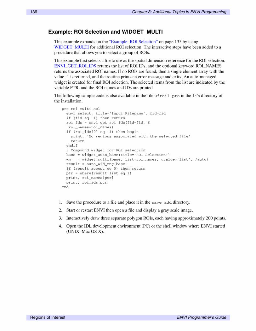
136 Chapter 8: Additional Topics in ENVI Programming
Example: ROI Selection and WIDGET_MULTI
This example expands on the “Example: ROI Selection” on page 135 by using WIDGET_MULTI for additional ROI selection. The interactive steps have been added to a procedure that allows you to select a group of ROIs.
This example first selects a file to use as the spatial dimension reference for the ROI selection. ENVI_GET_ROI_IDS returns the list of ROI IDs, and the optional keyword ROI_NAMES returns the associated ROI names. If no ROIs are found, then a single element array with the value -1 is returned, and the routine prints an error message and exits. An auto-managed widget is created for final ROI selection. The selected items from the list are indicated by the variable PTR, and the ROI names and IDs are printed.
The following sample code is also available in the file ufroi1.pro in the lib directory of the installation.
pro roi_multi_sel envi_select, title='Input Filename', fid=fid if (fid eq -1) then return roi_ids = envi_get_roi_ids(fid=fid, $ roi_names=roi_names) if (roi_ids[0] eq -1) then begin print, 'No regions associated with the selected file' return endif ; Compound widget for ROI selection base = widget_auto_base(title='ROI Selection') wm = widget_multi(base, list=roi_names, uvalue='list', /auto) result = auto_wid_mng(base) if (result.accept eq 0) then return ptr = where(result.list eq 1) print, roi_names[ptr] print, roi_ids[ptr]end
1. Save the procedure to a file and place it in the save_add directory.
2. Start or restart ENVI then open a file and display a gray scale image.
3. Interactively draw three separate polygon ROIs, each having approximately 200 points.
4. Open the IDL development environment (PC) or the shell window where ENVI started (UNIX, Mac OS X).
Regions of Interest ENVI Programmer’s Guide

Chapter 8: Additional Topics in ENVI Programming 137
5. Type the following at the ENVI command line to run the routine:
roi_multi_sel
The sample code in this example can be used as a model for allowing ROI selection in user functions.
Example: Restore Saved ROIs
This example interactively restores a saved ROI file. The compound widget ENVI_PICKFILE is used to select the file, and the returned filename is then passed to ENVI_RESTORE_ROIS. An informational message is displayed showing the restored ROIs.
1. Start ENVI.
2. Open a file and display a gray scale image.
3. Interactively draw three separate polygon ROIs, each having approximately 200 points.
4. Save the ROIs to a file.
5. Open the IDL development environment (PC) or the shell window where ENVI started (UNIX, Mac OS X).
6. Type the following at the ENVI command line to select the ROI file you saved above:
name = ENVI_PICKFILE(title='ROI File', filter='*.roi')
7. Type the following at the ENVI command line to restore the saved ROIs:
ENVI_RESTORE_ROIS, name
Now two sets of the same ROIs are loaded into ENVI: the ones created interactively and the ones loaded from the file. Although these two sets originated from the same source, they are now considered independent.
Using ROI Data
Once you select an ROI, acquiring and processing the data is quite simple. The ROI data are returned in an array using ENVI_GET_ROI_DATA. The file from which to extract the data is defined by the FID variable passed into ENVI_GET_ROI_DATA.
The following examples build on the previous ROI selection examples by adding the data request.
Example: Using ROI Data
Basic ROI selection uses ENVI_GET_ROI_IDS with an associated spatial dimension. This example shows how to interactively select all ROIs associated with the spatial dimensions specified by FID. The ROI data from the first band are accessed using ENVI_GET_ROI_DATA. The ROI mean for this band is calculated and printed.
1. Start ENVI.
2. Open a file and display a gray scale image.
3. Interactively draw one polygon ROI with approximately 200 points.
4. Open the IDL development environment (PC) or the shell window where ENVI was started (UNIX, Mac OS X).
ENVI Programmer’s Guide Regions of Interest

138 Chapter 8: Additional Topics in ENVI Programming
5. Type the following at the ENVI command line to select the displayed file. Select the displayed file (the gray scale image):
ENVI_SELECT, title='Input Filename', fid=fid, pos=pos
6. Type the following at the ENVI command line to get all the ROIs with the same spatial dimensions as the file specified by FID:
roi_ids = ENVI_GET_ROI_IDS(fid=fid)
7. Type the following at the ENVI command line to get the ROI data for the first band, and calculate the ROI mean value:
data = ENVI_GET_ROI_DATA(roi_ids[0], fid=fid, pos=pos[0])print, 'ROI mean = ', total(data) / n_elements(data)
To access any remaining bands in the POS array, ENVI_GET_ROI_DATA is called again with the POS keyword set to the next element. This process continues in a loop until all bands have been accessed. Or, the ROI data from all of the bands in the file can be extracted in a single call to ENVI_GET_ROI_DATA. This interactive example is for demonstration purposes only. In practice, these steps are part of a user function.
Example: Calculating ROI Means
This example extends the “Example: ROI Selection and WIDGET_MULTI” on page 136 to request ROI data and calculate the ROI mean.
This example uses ENVI_SELECT to select the file to use as the spatial dimension reference. Then, ENVI_GET_ROI_IDS returns return the list of ROI IDs, and the keyword ROI_NAMES returns the associated ROI name. If no ROIs are found, then a single element array with the value –1 is returned and the routine prints an error message and exits. Next, an auto-managed widget is created for the final ROI selection. The selected items from the list are indicated by the variable PTR. The data for each band of a selected ROI is read, and the mean value is computed. The resulting mean values are printed.
The following sample code is also available in the file ufroi2.pro in the lib directory of the installation.
pro roi_mean envi_select, title='Input Filename', fid=fid, pos=pos if (fid eq -1) then return roi_ids = envi_get_roi_ids(fid=fid, roi_names=roi_names) if (roi_ids[0] eq -1) then begin print, ‘No regions associated with the selected file’ return endif ; Compound widget for ROI selection base = widget_auto_base(title='ROI Selection') wm = widget_multi(base, list=roi_names, uvalue='list', /auto) result = auto_wid_mng(base) if (result.accept eq 0) then return ptr = where(result.list eq 1, count) result = dblarr(n_elements(pos)) ; ROI Mean calculation for i=0L count-1 do begin for j=0L, n_elements(pos)-1 do begin data = envi_get_roi_data(roi_ids[ptr[i]], fid=fid, $ pos=pos[j]) result[j] = total(data, /double) / n_elements(data)
Regions of Interest ENVI Programmer’s Guide

Chapter 8: Additional Topics in ENVI Programming 139
endfor print, roi_names[ptr[i]] print, result endforend
8. Save the procedure to a file and place it in the save_add directory.
9. Start or restart ENVI.
10. Open a file and display a gray scale image.
11. Interactively draw three separate polygon ROIs, each having approximately 200 points.
12. Open the IDL development environment (PC) or the shell window where ENVI started (UNIX, Mac OS X).
13. Type the following at the ENVI command line to run the routine:
roi_mean
The sample code in this example is a useful model for adding ROI selection to user functions. To calculate ROI statistics, you should use ENVI_STATS_DOIT and set the ROI DIMS pointer.
Using ROI DIMS Pointers
In many ENVI routines, you have the option to spatially subset an image using an ROI instead of specifying a range of samples and lines. In ENVI programming routines, the DIMS variable is used to define the spatial subset. The first element of the DIMS variable is called the ROI pointer, which tells ENVI if the spatial subset should be based on an ROI. When the ROI pointer is set to a value of -1L, it means an ROI is not being used. Properly set the ROI pointer using the routine ENVI_GET_ROI_DIMS_PTR.
NoteAn ROI DIMS pointer value can change when ROIs are added or deleted. It is best to convert the ROI IDs when defining the DIMS array.
Example: ROI DIMS Pointer
This example converts the “Example: Calculating ROI Means” on page 138 by using ENVI_STATS_DOIT to calculate the ROI statistics.
This example shows you how to select the image file used as the spatial reference for the ROIs. Next, use ENVI_GET_ROI_IDS to return the list of ROI IDs, and use the keyword ROI_NAMES to return the associated ROI name. If no ROIs are found, then a single element array with the value -1 is returned, and the routine prints an error message and exits. Create an auto-managed widget for the final ROI selection. The selected items from the list are indicated by the variable PTR. Calculate the basic statistics for each selected ROI using ENVI_STATS_DOIT. Print the resulting minimum, maximum, mean, and standard deviation vectors.
The sample code is also available in the file ufroi3.pro in the lib directory of the installation.
ENVI Programmer’s Guide Regions of Interest

140 Chapter 8: Additional Topics in ENVI Programming
pro roi_stat envi_select, title='Input Filename', fid=fid, pos=pos if (fid eq -1) then return roi_ids = envi_get_roi_ids(fid=fid, roi_names=roi_names) if (roi_ids[0] eq -1) then begin print, 'No regions associated with the selected file' return endif ; Compound widget for ROI selection base = widget_auto_base(title='ROI Selection') wm = widget_multi(base, list=roi_names, uvalue='list', /auto) result = auto_wid_mng(base) if (result.accept eq 0) then return ptr = where(result.list eq 1, count) result = dblarr(n_elements(pos)) ; ROI Stats calculation for i=0L, count-1 do begin dims = [envi_get_roi_dims_ptr(roi_ids[ptr[i]]), 0,0,0,0] envi_stats_doit, fid=fid, dims=dims, pos=pos, comp_flag=0, $ report_flag=0, mean=mean, stdv=stdv, dmin=dmin, dmax=dmax print, roi_names[ptr[i]] print, dmin, dmax, mean, stdvendforend
1. Save the procedure to a file and place it in the save_add directory.
2. Start or restart ENVI.
3. Open a file and display a gray scale image.
4. Interactively draw three separate polygon ROIs, each having approximately 200 points.
5. Open the IDL development environment (PC) or the shell window where ENVI started (UNIX, Mac OS X).
6. Type the following at the ENVI command line to run the routine:
roi_stat
The sample code in this example is a useful model for calculating statistics for ROIs.
Using ROI Addresses
ENVI provides access to the spatial location of any ROI through its addresses. ROI addresses are single-element addresses referenced from the first pixel in the image, increasing in the sample direction. The following list shows some sample ROI addresses and their corresponding pixels for an image with ten samples and eight lines.
• 0: First pixel in the image
• 12: Third pixel on the second line
• 30: First pixel on the third line
• 79: Last pixel in the image
Regions of Interest ENVI Programmer’s Guide

Chapter 8: Additional Topics in ENVI Programming 141
The routine ENVI_GET_ROI returns the address associated with the specified ROI. If necessary, the address can be converted to spatial x and y values (see the following example). ROI addresses are zero-based, where the first pixel in the image has an address of 0.
Example: ROI Addresses
This example computes the x and y values for a ROI address. The ROI selection uses ENVI_GET_ROI_IDS with an associated spatial dimension using the keyword FID. The FID is returned using the compound widget ENVI_SELECT. Next, convert the ROI address returned from ENVI_GET_ROI to x,y locations and print them.
1. Start ENVI.
2. Open a file and display a gray scale image.
3. Interactively draw one polygon ROI with approximately 200 points.
4. Open the IDL development environment (PC) or the shell window where ENVI started (UNIX, Mac OS X).
5. Type the following at the ENVI command line to select the displayed file (gray scale image):
ENVI_SELECT, title='Input Filename', fid=fid
6. Type the following at the ENVI command line to get all the ROIs with the same spatial dimensions as the file specified by FID:
roi_ids = ENVI_GET_ROI_IDS(fid=fid)
7. Type the following at the ENVI command line to get the ROI address:
addr = ENVI_GET_ROI(roi_ids[0])
8. Get the number of samples and lines in the file specified by FID:
ENVI_FILE_QUERY, fid, ns=ns, nl=nl
9. Calculate and print the x,y location for each point in the ROI:
y = addr / nsx = addr - y * nsprint, xprint, y
This interactive example is for demonstration purposes only. In practice, these steps are part of a user function.
ENVI Programmer’s Guide Regions of Interest

142 Chapter 8: Additional Topics in ENVI Programming
Using Endmember Collection Widgets
The Endmember Collection dialog is one of ENVI’s most sophisticated compound widgets. It is used to collect training sets and endmembers for classification and mapping routines, and it can be incorporated into user functions with the routine ENVI_COLLECT_SPECTRA. However, this widget functions differently than all of the other ENVI widgets, and it requires some special instruction. (For users that are familiar with IDL widget programming, using the Endmember Collection widget is essentially no different than writing a custom event handler for the widget’s Apply button).
The Endmember Collection Dialog is not modal (see “Adding Widgets to User Functions” on page 53 for an explanation of modality). After this dialog widow is displayed, all of ENVI’s menus remain active. The primary reason this widget is not modal is because it serves as a repository of endmember spectra that can be used for a wide variety of routines. Thus, it makes sense to allow continued access to the widget after the original processing is finished. However, while not being modal makes the widget more functional, it also makes it more complicated to use.
A user function that produces the Endmember Collection widget is broken into two parts. The first procedure is defined in the menu file and is executed when you select the user function from the ENVI main menu bar. This procedure ends after it calls ENVI_COLLECT_SPECTRA.
The second procedure is executed when you click Apply. Instead of the widget returning the data in a structure variable, ENVI automatically calls this procedure into which the endmember data are passed. The name of the procedure is defined by the PROCEDURE keyword to ENVI_COLLECT_SPECTRA. This second procedure uses the information
Figure 8-1: Endmember Collection Widget
Using Endmember Collection Widgets ENVI Programmer’s Guide

Chapter 8: Additional Topics in ENVI Programming 143
collected by the widget to carry out the user function’s processing. Because the Endmember Collection dialog remains open, you can modify the contents of the dialog window and run the second part of the user function multiple times by clicking Apply.
In IDL widget programming, this second procedure is referred to as an event handler because it handles the widget event that occurs when you click Apply. This event-handling procedure can have any name, but you must define the following keywords in the procedure definition statement:
PRO MyEventHandler, fid=fid, pos=pos, dims=dims, $ spec=spec, snames=snames, scolors=scolors, _extra=extra
The FID, POS, and DIMS variables are passed into ENVI_COLLECT_SPECTRA when it is called. SPEC, SNAMES, and SCOLORS are collected by the Endmember Collection widget. The _EXTRA keyword passes additional information from the first procedure (the one that called ENVI_COLLECT_SPECTRA) to the event-handling procedure.
The two procedures that comprise the single user function are frequently included in the same file. With this organization, the first procedure (the one defined in the menu file) must be the last procedure in the file. Otherwise, IDL will not auto-compile both procedures when it starts ENVI. The file that contains the user function has the following structure:
PRO MyEventHandler, fid=fid, pos=pos, dims=dims, $ spec=spec, snames=snames, scolors=scolors, _extra=extra do the user function processing...END
PRO MyUserFunction, event ENVI_SELECT, fid=fid, pos=pos, dims=dims info = {structure variable of useful information} do any pre-processing if necessary ENVI_COLLECT_SPECTRA, dims=dims, fid=fid, pos=pos,$ title=title, procedure='MyEventHandler',$ h_info=infoEND
ENVI Programmer’s Guide Using Endmember Collection Widgets

144 Chapter 8: Additional Topics in ENVI Programming
Working with Display Groups
While writing user functions, you may want to programmatically retrieve information about a display group. Each display group is identified by a unique display number (DN). Once a DN for a particular display is obtained, several different ENVI routines provide useful information about the displayed image data, along with controls for moving the position of the Zoom window.
DISP_GET_LOCATION
This routine returns the x,y location of the current pixel. See “DISP_GET_LOCATION” in the ENVI Reference Guide for a complete description, list of associated keywords, and example usage.
DISP_GOTO
Use this procedure to move the current pixel of a given display. The Zoom window also moves so that it is centered around the new current pixel location. If this location is not within the current display group, the Image and Scroll windows also move so that they include the new current pixel.
See “DISP_GOTO” in the ENVI Reference Guide for a complete description, list of associated keywords, and example usage.
ENVI_CLOSE_DISPLAY
Use the ENVI_CLOSE_DISPLAY procedure to close all three windows of a display group. Use the DN variable to specify the display number for the display group you want to close. See “ENVI_CLOSE_DISPLAY” in the ENVI Reference Guide for a complete description, list of associated keywords, and example usage.
ENVI_DISP_QUERY
This routine provides fundamental file information about the displayed image, including the FID of the image file, its spatial dimensions, its type (RGB, gray scale, or classification), the band positions that are displayed, and the size (in pixels) of the windows in the display group.
Use the W1 keyword to find the window IDs for the Image, Zoom, and Scroll windows of a display group. This window ID is not the draw widget ID for the display group windows. It is the value of !d.window, which you can use with IDL's WSET or WSHOW routines.
Obtain the zoom and resize factors using the ZFACT and REBIN keywords, respectively.
See “ENVI_DISP_QUERY” in the ENVI Reference Guide for a complete description, list of associated keywords, and example usage.
Working with Display Groups ENVI Programmer’s Guide
Chapter 8: Additional Topics in ENVI Programming 145
ENVI_GET_IMAGE
This routine is equivalent to ENVI_GET_DATA, except that it returns data displayed in the display group instead of that stored in an image file. Given the band positions, dimensions, and DN, ENVI_GET_IMAGE returns the bytescale-stretched data. See “ENVI_GET_IMAGE” in the ENVI Reference Guide for a complete description, list of associated keywords, and example usage.
ENVI Programmer’s Guide Working with Display Groups

146 Chapter 8: Additional Topics in ENVI Programming
ENVI Installation Components
After installing ENVI, you will find an envixx directory containing several subdirectories. Some of these subdirectories contain files that are particularly important for ENVI programming. These are defined in the following tables.
ENVI Subdirectories
ENVI includes the following subdirectories.
Subdirectory Contents
bin envi.run: A special ASCII file used by IDL to auto-start ENVI
data ENVI’s default data directory, which contains example data distributed with ENVI
filt_func Filter function spectral library files for resampling to known sensors
help ENVI Help files and PDF versions of the documentation
lib Example ENVI code (sample IDL procedures using some of the ENVI routines)
map_proj Files that store the data related to ENVI map projections
menu A variety of setup and configuration files, including the menu definition files
save The ENVI save files (.sav)
save_add Recommended storage location for user-written code, such as user functions
spec_lib ENVI spectral library files
Table 8-1: ENVI Subdirectories
ENVI Installation Components ENVI Programmer’s Guide
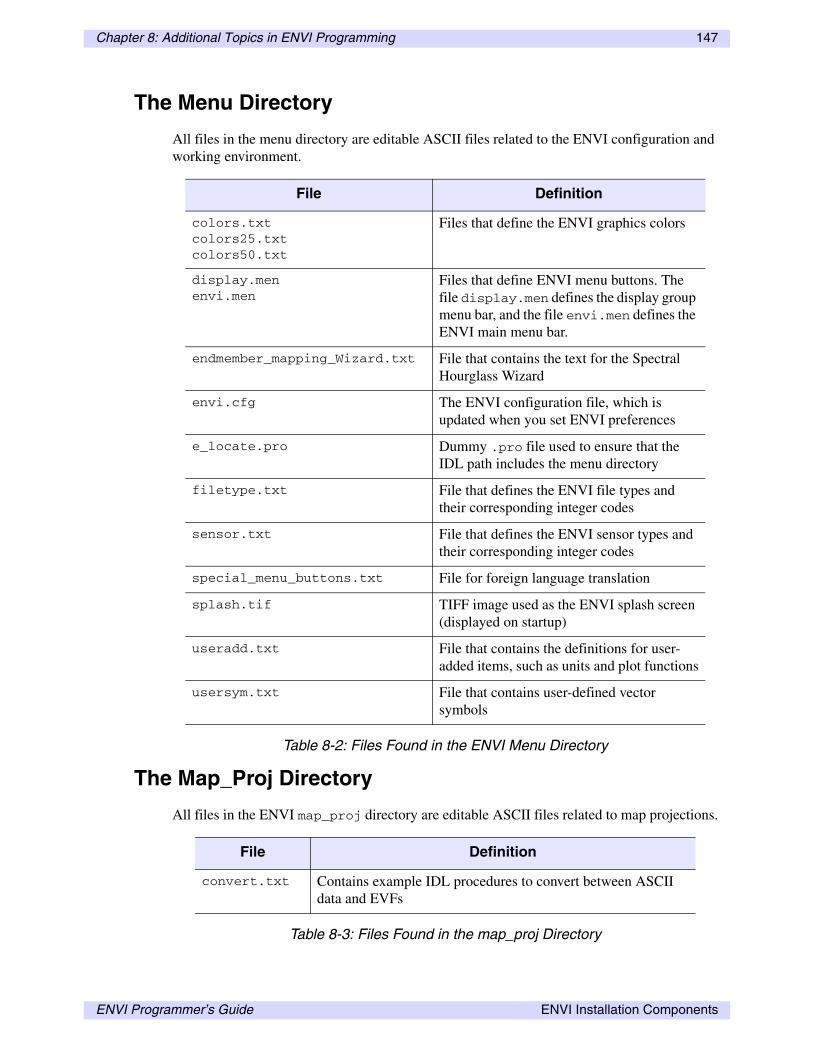
Chapter 8: Additional Topics in ENVI Programming 147
The Menu Directory
All files in the menu directory are editable ASCII files related to the ENVI configuration and working environment.
The Map_Proj Directory
All files in the ENVI map_proj directory are editable ASCII files related to map projections.
File Definition
colors.txt colors25.txt colors50.txt
Files that define the ENVI graphics colors
display.men envi.men
Files that define ENVI menu buttons. The file display.men defines the display group menu bar, and the file envi.men defines the ENVI main menu bar.
endmember_mapping_Wizard.txt File that contains the text for the Spectral Hourglass Wizard
envi.cfg The ENVI configuration file, which is updated when you set ENVI preferences
e_locate.pro Dummy .pro file used to ensure that the IDL path includes the menu directory
filetype.txt File that defines the ENVI file types and their corresponding integer codes
sensor.txt File that defines the ENVI sensor types and their corresponding integer codes
special_menu_buttons.txt File for foreign language translation
splash.tif TIFF image used as the ENVI splash screen (displayed on startup)
useradd.txt File that contains the definitions for user-added items, such as units and plot functions
usersym.txt File that contains user-defined vector symbols
Table 8-2: Files Found in the ENVI Menu Directory
File Definition
convert.txt Contains example IDL procedures to convert between ASCII data and EVFs
Table 8-3: Files Found in the map_proj Directory
ENVI Programmer’s Guide ENVI Installation Components
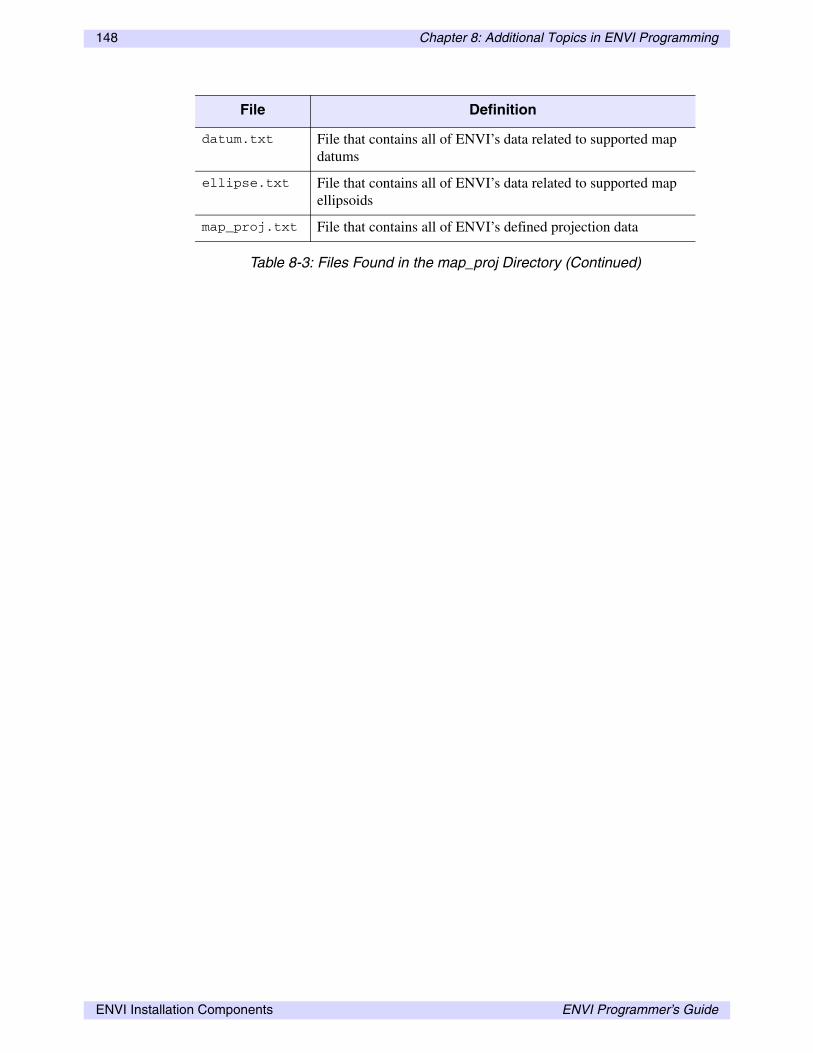
148 Chapter 8: Additional Topics in ENVI Programming
datum.txt File that contains all of ENVI’s data related to supported map datums
ellipse.txt File that contains all of ENVI’s data related to supported map ellipsoids
map_proj.txt File that contains all of ENVI’s defined projection data
File Definition
Table 8-3: Files Found in the map_proj Directory (Continued)
ENVI Installation Components ENVI Programmer’s Guide

Index
Aauto-managed widget events, 61
Bband math
user functions, 19batch mode, 30
example routines, 40exiting, 33helpful tips, 38hybrid, 30initializing, 31message logging, 37recording, 35shortcuts, 38writing routines, 34
CCATCH, 66compiling code, 12copyrights, 2crashes, 50
DDIMS pointers, 139display groups
programming tools, 144
Eendmember collection
widgets, 142ENVI header file
parsing, 123ENVI image format
creating, 98ENVI save files, 14
creating, 80use in batch mode, 31
error handling (programming), 65checking, 51input/output errors, 65toggle catch, 13using CATCH, 66
Ffile management, 94
ENVI Programmer’s Guide 149

150
custom file readers, 125spatial read routines, 126spectral read routines, 128
ENVI and IDL input/output, 15querying file information, 92querying map information, 92
Hhybrid batch mode, 30
IIDL
multiple versions, 31images
coordinates, 132retrieving spatial and spectral information, 97
input error handling, 65input file dialogs, 95installation directories, 146
Llegalities, 2library directories, 15library routines, 14
IDL compilation errors, 34
Mmanaging files, 94map projections
querying information, 92menus
directory, 147modifying, 47user values, 48
multipart polygons, 88
Nnon-tiled processing, 76
Oopening files, 94
outputerror handling, 65
Ppixels
coordinates, 132plots
programming tools, 85overview and example, 85plot functions, 103
processing statusreports, 78
programmingexamples
multipart vectors, 88programming in ENVI, 14
band math user functions, 19batch mode, 30compiling, 12display groups, 144examples
band math, 20basic image information, 92calculating file statistics, 40calculating ROI means, 138choosing files interactively, 96creating a report, 90getting RGB color values, 91input/output error handling, 65map information, 92non-tiled spatial processing, 77non-tiled spectral processing, 77parsing image headers, 123parsing positional headers, 124plot functions, 104plotting data, 85processing status dialog, 78restoring saved ROIs, 137ROI addresses, 141ROI DIMS pointer, 139saturation stretch, 41saving spatial tiles to disk, 72saving spatial tiles to memory, 74saving spectral tiles to disk, 75selecting ROIs, 135selecting ROIs using WIDGET_MULTI, 136simple batch mode routine, 34simple GUI with widgets, 62
Index ENVI Programmer’s Guide

151
simple user function, 49spatial and spectral tiling, 71spatial read routines, 126spatial tiling, 69Spectral Analyst functions, 106spectral math, 24spectral read routines, 128spectral tiling, 70user-defined map projections, 109user-defined motion routines, 118user-defined move routines, 116user-defined RPC readers, 113using ROI data, 137widget user-defined move routines, 117
file information, 92file management, 94file readers, 125interactive user routines, 102parsing headers, 123plotting, 85processing status reports, 78reports, 90RGB triplets, 91ROIs, 134saving processing results, 72spatial read routines, 126spectral math user functions, 24spectral read routines, 128tiling, 67toggle catch, 13
Rreporting, 90RESOLVE_ALL, 80RGB
color triplets, 91ROIs
programming, 134addresses, 140DIMS pointers, 139obtaining data, 137selecting, 134
routinescompiling dependent, 80non-tiled processing, 76processing, 67
Ssaving
processing results, 72spatial read routines, 126spectral analyst, 105spectral math
user functions, 24spectral read routines, 128status reports, 78symbols
user-defined vector symbols, 86
Ttiled processing, 76tiling, 67
examplesnon-tiled spatial processing, 77non-tiled spectral processing, 77saving results, 72saving spatial tiles to disk, 72saving spatial tiles to memory, 74saving spectral tiles to disk, 75spatial, 69spatial and spectral, 71spectral, 70
non-tiled routines, 76processing, 67
toggle catch, 13trademarks, 2
Uuser functions, 46
adapting for ENVI, 80adding widgets, 53auto-managed widget events, 61checking errors, 51input/output error handling, 65processing routines and tiling, 67recovering from crashes, 50trapping errors, 65unexpected errors, 66as widget event handlers, 46
user move routines, 115user-defined, 102
map projection types, 108motion routines, 118
ENVI Programmer’s Guide Index

152
move routines, 115RPC readers, 111
Vvectors
multipart, 88user-defined symbols, 86
Wwidgets
adding to user functions, 53
auto-managed events, 61compound, 54endmember collection, 142event handlers, 46examples, 54
XXSTART, 132
YYSTART, 132
Index ENVI Programmer’s Guide