environment dust-tight/water-jet-proof (ip65 equivalent)model selection ley-x5 series step motor...
TRANSCRIPT

Groove for auto switch
Tubing∗ Order separately.
Lube-retainer(Except LEY63)Retains grease oil film.
Scraper
Water resistant type For checking the limit and intermediate signal∗ Order the water resistant 2-color indicator
solid state auto switch separately.
Vent hole
Seal connector
Aluminum coverProtects the motor.
Prevents dust and water droplets from entering between the cable and motor cover.
Reduces internal pressure fluctuation to prevent dust and water droplets from entering.∗ Be sure to attach tubing.∗ For size 63, order a fitting separately.
Enclosure: IP65 equivalent Note)
Max. stroke: 500 mm** For size 32
LEY-X5 (Made to Order) LEY63mmm-mPType Type
Type
Page 486 * Select options
63Size25, 32Size
Step Motor (Servo/24 VDC) AC Servo Motor (400 W)
AC Servo Motor (100/200 W)
Servo Motor (24 VDC) Page 500
Page 494
Environment Dust-tight/Water-jet-proof (IP65 Equivalent)
Note) IP65 enclosure: The protection structure against solid foreign objects is dust-tight type and the protection structure against water is water-jet-proof type.Dust-tight means that no dust can enter the inside of the equipment.Water-jet-proof means that the product is not adversely affected by direct water jets from any direction. That is, even when direct water jets are applied to the product for 3 minutes by means of the pre-determined method, there is no water entry that hinders correct operation inside the equipment. Be sure to take appropriate protection measures when the product is used in an environment where it is constantly exposed to water or fluids other than water splash. In particular, the product cannot be used in an environment with oil, such as cutting oil or cutting fluid.
485
LEF
LAT
LEJ
LEL
LEY
LEM
LESLEPYLEPS
LEY-X5
LECSLECSS-T
LECYMotor-less
11-LEFS
11-LEJS
LER
LEH
25A-
LEC
LZ
LC3F2
LEY-X5
A

Hor
izon
tal w
ork
load
[kg]
Speed [mm/s]
0
10
20
30
40
505560
70
80
0 300200 400100 500 600
Lead 3: LEY25C
Lead 6: LEY25B
Lead 12: LEY25A
Hor
izon
tal w
ork
load
[kg]
Speed [mm/s]
0
10
20
30
404550
60
70
80
90
0 300200 400100 500 600
Lead 4: LEY32C
Lead 8: LEY32B
Lead 16: LEY32A
Ver
tical
wor
k lo
ad [k
g]Speed [mm/s]
0
10
20
30
35
29
15
7
0 300200 400100 500 600
Lead 3: LEY25C
Lead 6: LEY25B
Lead 12: LEY25A
Ver
tical
wor
k lo
ad [k
g]
Speed [mm/s]
0
10
20
30
4042
50
0 300200 400100 500 600
21
Lead 4: LEY32C
Lead 8: LEY32B
Lead 16: LEY32A
Load
: F [N
]
Stroke [mm]
100
10
10 300200 400100 500 600
LEY32
LEY25
F
Center of gravity
Workpiece
Graph of Allowable Lateral Load on the Rod End (Guide)
[Stroke] = [Product stroke] + [Distance from the rod end to the center of gravity of the workpiece]
Step Motor (Servo/24 VDC) Servo Motor (24 VDC)
Electric Actuator/Rod TypeLEY-X5 Series Dust-tight/Water-jet-proof (IP65 Equivalent)
Model SelectionLEY-X5 SeriessPage 486
Speed–Work Load Graph (Guide) for Step Motor (Servo/24 VDC) LECP6, LECP1, LECPMJ
Horizontal Vertical
LEY25m
LEY32m LEY32m
LEY25m for acceleration/deceleration: 2000 mm/s2
for acceleration/deceleration: 2000 mm/s2
Refer to page 229 for the LECPA or LECA6.
228

Hor
izon
tal w
ork
load
[kg]
Speed [mm/s]
0
10
20
12
30
18
40
50
60
70
80
0 300200 400100 500 600
Lead 3: LEY25C
Lead 6: LEY25B
Lead 12: LEY25A
Hor
izon
tal w
ork
load
[kg]
Speed [mm/s]
0
10
20
30
40
50
60
80
70
90
0 300200 400100 500 600
Lead 4: LEY32C
Lead 8: LEY32B
Lead 16: LEY32A
Ver
tical
wor
k lo
ad [k
g]
Speed [mm/s]
0
10
20
30
35
29
15
7
0 300200 400100 500 600
Lead 3: LEY25C
Lead 6: LEY25B
Lead 12: LEY25A
Ver
tical
wor
k lo
ad [k
g]
Speed [mm/s]
0
10
2021
30
4042
50
0 300200 400100 500 600
Lead 4: LEY32C
Lead 8: LEY32B
Lead 16: LEY32A
Hor
izon
tal w
ork
load
[kg]
Speed [mm/s]
0
10
20
30
15
7
40
0 300200 400100 500 600
Lead 3: LEY25AC
Lead 6: LEY25AB
Lead 12: LEY25AA
Ver
tical
wor
k lo
ad [k
g]
Speed [mm/s]
0
10
5
2
11
15
0 300200 400100 500 600
Lead 3: LEY25C
Lead 6: LEY25B
Lead 12: LEY25A
Horizontal Vertical
LEY25m
LEY32m LEY32m
LEY25m
Speed–Work Load Graph (Guide)For Step Motor (Servo/24 VDC) LECPA
for acceleration/deceleration: 2000 mm/s2
for acceleration/deceleration: 2000 mm/s2
Refer to page 228 for the LECP6, LECP1, LECPMJ.
Horizontal Vertical
LEY25Am LEY25m
For Servo Motor (24 VDC) LECA6
229
Model Selection LEY-X5 SeriesStep Motor (Servo/24 VDC) Servo Motor (24 VDC) Dust-tight/Water-jet-proof (IP65 Equivalent)
LEF
LAT
LEJ
LEL
LEY
LEM
LESLEPYLEPS
LEY-X5
LECSLECSS-T
LECYMotor-less
11-LEFS
11-LEJS
LER
LEH
25A-
LEC
LZ
LC3F2
LEY

Force Conversion Graph
Step Motor (Servo/24 VDC) Servo Motor (24 VDC)
LEY25
LEY32
LEY25
<Pushing Force and Trigger Level Range> Without Load
<Set Values for Vertical Upward Transfer Pushing Operation>For vertical loads (upward), set the pushing force to the maximum value shown below, and operate at the work load or less.
* Set values for the controller.
For
ce [N
]
Set value of pushing force∗ [%]
Lead 3: LEY25C
Lead 6: LEY25B
Lead 12: LEY25A
10 20 30 40 50 60 70 80 900
100
200
300
400
500
Max. 65%
Set value of pushing force∗ [%]
For
ce [N
]
Lead 4: LEY32C
Lead 8: LEY32B
Lead 16: LEY32A
10 20 30 40 50 60 70 80 90
Max. 85%
0
100
200
300
400
500
600
700
800
Set value of pushing force∗ [%]F
orce
[N]
Max. 95%
Lead 3: LEY25AC
Lead 6: LEY25AB
Lead 12: LEY25AA
20 30 40 50 60 70 80 90 1000
20
40
60
80
100
120
140
Model LEY25 LEY32 LEY25ALead A B C A B C A B C
Work load [kg] 2.5 5 10 4.5 9 18 1.2 2.5 5Pushing force 65% 85% 95%
Model Pushing speed[mm/s]
Pushing force(Setting input value) Model Pushing speed
[mm/s]Pushing force(Setting input value)
LEY251 to 4 20% to 65%
LEY25A1 to 4 40% to 95%
5 to 20 35% to 65% 5 to 20 60% to 95%
21 to 35 50% to 65% 21 to 35 80% to 95%
LEY321 to 4 20% to 85%
5 to 20 35% to 85%
21 to 30 60% to 85%
Ambient temperatureSet value of pushing force*
[%]Duty ratio
[%]Continuous pushing time
[minute]
40°C or less 95 or less 100 —
Ambient temperatureSet value of pushing force*
[%]Duty ratio
[%]Continuous pushing time
[minute]
25°C or less 85 or less 100 —
40°C65 or less 100 —
85 50 15
Ambient temperatureSet value of pushing force*
[%]Duty ratio
[%]Continuous pushing time
[minute]
40°C or less 65 or less 100 —
230
LEY-X5 SeriesStep Motor (Servo/24 VDC) Servo Motor (24 VDC) Dust-tight/Water-jet-proof (IP65 Equivalent)

Speed [mm/s]
Wor
k lo
ad [k
g]
0
5
10
15
20
25
30
35
40
0 200 400 600 800 1000 1200
Lead 3: LEY25C
Lead 12: LEY25A
Lead 6: LEY25B
T1
a1 a2
L
Spe
ed: V
[mm
/s]
Time [s]
T2 T3 T4
W
Step 1 Check the work load–speed. <Speed–Vertical work load graph>
Step 2 Check the cycle time.
Workpiece mass: 16 [kg] Speed: 300 [mm/s]
Acceleration/Deceleration: 5000 [mm/s2]
Stroke: 300 [mm]
Workpiece mounting condition: Vertical upward downward transfer
Operatingconditions
Selection Procedure
Positioning Control Selection Procedure
Selection Example
Step 1Check the work load–speed.(Vertical transfer) Step 2 Check the cycle time.
Calculate the cycle time using the following calculation method.
Cycle time T can be found from the following equation.
Select the target model based on the workpiece mass and speed with reference to the <Speed–Vertical work load graph>.
Selection example) The LEY25B is temporarily selected based on the graph shown on the right side.
T = T1 + T2 + T3 + T4 [s]
T1 = V/a1 [s]
T4 = 0.05 [s]
T3 = V/a2 [s]
T2 = [s]L − 0.5 · V · (T1 + T3)
V
T4: Settling time varies depending on the motor type and load. The value below is recommended.
T2: Constant speed time can be found from the following equation.
T1: Acceleration time and T3: Deceleration time can be obtained by the following equation.
L : Stroke [mm] ⋅⋅⋅ (Operating condition)V : Speed [mm/s] ⋅⋅⋅ (Operating condition)a1: Acceleration [mm/s2] ⋅⋅⋅ (Operating condition)a2: Deceleration [mm/s2] ⋅⋅⋅ (Operating condition)
T1: Acceleration time [s] ⋅⋅⋅ Time until reaching the set speedT2: Constant speed time [s] ⋅⋅⋅ Time while the actuator is
operating at a constant speedT3: Deceleration time [s] ⋅⋅⋅ Time from the beginning of the
constant speed operation to stopT4: Settling time [s] ⋅⋅⋅ Time until positioning is completedCalculation example)
T1 to T4 can be calculated as follows.
T1 = V/a1 = 300/5000 = 0.06 [s], T3 = V/a2 = 300/5000 = 0.06 [s]
T4 = 0.05 [s]
Therefore, the cycle time can be obtained as follows.T = T1 + T2 + T3 + T4 = 0.06 + 0.94 + 0.06 + 0.05 = 1.11 [s]
T2 = = = 0.94 [s] L − 0.5 · V · (T1 + T3)
V
300 − 0.5 · 300 · (0.06 + 0.06)
300
<Speed–Vertical work load graph>(LEY25)
∗ It is necessary to mount a guide outside the actuator when used for horizontal transfer.When selecting the target model, refer to the horizontal work load in the specifications on pages 256, 265, 495 and 501, and the precautions.
Based on the above calculation result, the LEY25B-300 is selected.
The regeneration option may be necessary. Refer to pages 234 and 235 for “Required Conditions for Regeneration Option”.
LEY SeriessPages 254, 264 LEY-X5 SeriessPages 494, 500
AC Servo MotorElectric Actuator/Rod TypeLEY/LEY-X5 Series Dust-tight/Water-jet-proof (IP65 Equivalent)
Model Selection 25, 32, 63Size
232

For
ce [N
]
Torque limit/Command value [%]
500
400
300
200
100
02010 4030
Lead 12: LEY25A
Lead 3: LEY25C
Lead 6: LEY25B
Jig
Load
: F [N
]
Stroke [mm]0 100 200 300 400 500 600
100
10
1
LEY32
LEY25
<Graph of allowable lateral load on the rod end>
Step 2 Check the force. <Force conversion graph>
Mounting condition: Horizontal (pushing) Duty ratio: 60 [%]
Jig weight: 0.5 [kg] Speed: 100 [mm/s]
Force: 255 [N] Stroke: 300 [mm]
Operatingconditions
Force Control Selection Procedure
Selection Example
Check the lateral load on the rod end.
Step 2 Check the force.
Select the target model based on the torque limit/command value and pushing force with reference to the <Force conversion graph>.
Selection example)Based on the graph shown on the right side,Torque limit/Command value: 30 [%]Force: 255 [N]Therefore, the LEY25B is temporarily selected.
Step 3 Check the lateral load on the rod end. <Graph of allowable lateral load on the rod end>Confirm the allowable lateral load on the rod end of the actuator: LEY25B, which has been selected temporarily with reference to the <Graph of allowable lateral load on the rod end>.
Selection example)Based on the graph shown on the right side,Jig weight: 0.5 [kg] ≈ 5 [N]Product stroke: 300 [mm]Therefore, the lateral load on the rod end is in the allowable range.
Step 3
<Force conversion graph>(LEY25)
Based on the above calculation result, the LEY25B-300 is selected.
Selection Procedure
Step 1 Check the duty ratio.
* The duty ratio is a ratio of the operation time in one cycle.
Step 1 Check the duty ratio.<Conversion table of force–duty ratio>Select the [Force] from the duty ratio with reference to the <Conversion table of force–duty ratio>.
Selection example)Based on the table below, Duty ratio: 60 [%]Therefore, Torque limit/Command value will be 30 [%].
* [Torque limit/Command value [%]] is the set value for the driver.* [Continuous pushing time] is the time that the actuator can continuously keep pushing.
<Conversion table of force–duty ratio>(LEY25/AC Servo motor)
Torque limit/Command value [%]
Duty ratio[%]
Continuouspushing time [minute]
25 or less 100 —
30 60 1.5
233
Model Selection LEY/LEY-X5 SeriesAC Servo Motor 25, 32, 63Size Dust-tight/Water-jet-proof (IP65 Equivalent)
LEF
LAT
LEJ
LEL
LEY
LEM
LESLEPYLEPS
LEY-X5
LECSLECSS-T
LECYMotor-less
11-LEFS
11-LEJS
LER
LEH
25A-
LEC
LZ
LC3F2
LEY

0
10
20
30
40
16
8
0 200 400 600 800 1000 1200Speed [mm/s]
Wor
k lo
ad [k
g]
Lead 3: LEY25C
Lead 6: LEY25B
Lead 12: LEY25A
Area where the regeneration option is required.
37
19
9
0 200 400 600 800 1000 140012000
10
20
30
40
50
Speed [mm/s]
Wor
k lo
ad [k
g]
Lead 5: LEY32C
Lead 10: LEY32B
Lead 20: LEY32A
Area where the regeneration option is required.
0 200 400 600 800 1000 12000
10
20
30
40
50
60
Speed [mm/s]
Wor
k lo
ad [k
g]
12
24
46
Lead 4: LEY32DC
Lead 8: LEY32DB
Lead 16: LEY32DA
Area where the regeneration option is required.
Speed [mm/s]
Wor
k lo
ad [k
g]
0
20
40
60
80
120
100
0 200 400 600 800 1000 1200 1400
Lead 5: LEY63C
Lead 2.86: LEY63L (Top/Parallel type only)
Lead 20: LEY63A
Area where the regeneration option is required.
Lead 10: LEY63B
Speed–Vertical Work Load Graph/Required Conditions for “Regeneration Option”
Required conditions for “Regeneration option”* Regeneration option is required when using product above regeneration line
in graph. (Order separately.)
“Regeneration Option” Models
LEY25 (Motor mounting position: Top/Parallel, In-line)
LEY32 (Motor mounting position: Top/Parallel) LEY32D (Motor mounting position: In-line)
LEY63 (Motor mounting position: Top/Parallel, In-line)
Size Model
LEY25 LEC-MR-RB-032
LEY32 LEC-MR-RB-032
LEY63 LEC-MR-RB-12
234
LEY/LEY-X5 SeriesAC Servo Motor 25, 32, 63Size Dust-tight/Water-jet-proof (IP65 equivalent)

0 200 400 600 800 1000 140012000
20
40
50
60
70
Speed [mm/s]
Wor
k lo
ad [k
g]
Lead 3: LEY25C
Lead 12: LEY25A
Lead 6: LEY25B
Area where the regeneration option is required.
0 200 400 600 800 1000 140012000
20
30
40
60
80
Speed [mm/s]
Wor
k lo
ad [k
g]
Area where the regeneration option is required.
Lead 5: LEY32C
Lead 20: LEY32A
Lead 10: LEY32B
0 200 400 600 800 1000 140012000
20
30
40
60
80
Speed [mm/s]
Wor
k lo
ad [k
g]
Lead 4: LEY32DC
Area where the regeneration option is required.
Lead 16: LEY32DA
Lead 8: LEY32DB
Speed [mm/s]
Wor
k lo
ad [k
g]
0
50
100
150
200
250
0 200 400 600 800 12001000
Lead 5: LEY63C
Lead 2.86: LEY63L (Top/Parallel type only)
Lead 20: LEY63A
Lead 10: LEY63B
Speed–Horizontal Work Load Graph/Required Conditions for “Regeneration Option”
Required conditions for “Regeneration option”* Regeneration option is required when using product above regeneration line
in graph. (Order separately.)
“Regeneration Option” Models
LEY25 (Motor mounting position: Top/Parallel, In-line)
LEY32 (Motor mounting position: Top/Parallel)
LEY63l (Motor mounting position: Top/Parallel, In-line)
LEY32D (Motor mounting position: In-line)
Allowable Stroke Speed [mm/s]
ModelAC servo
motorLead Stroke [mm]
Symbol [mm] 30 50 100 150 200 250 300 350 400 450 500 600 700 800
LEY25Motor mounting position:
Top/Parallel, In-line
100 W/40
A 12 900 600 — — —B 6 450 300 — — —C 3 225 150 — — —
(Motor rotation speed) (4500 rpm) (3000 rpm) — — —
LEY32Motor mounting position:
Top/Parallel
200 W/60
A 20 1200 800 —B 10 600 400 —C 5 300 200 —
(Motor rotation speed) (3600 rpm) (2400 rpm) —
LEY32DMotor mounting position:
In-line
200 W/60
A 16 1000 640 —B 8 500 320 —C 4 250 160 —
(Motor rotation speed) (3750 rpm) (2400 rpm) —
LEY63Motor mounting position:
Top/Parallel, In-line
400 W/60
A 20 1000 800 600 500B 10 500 400 300 250C 5 250 200 150 125
(Motor rotation speed) (3000 rpm) (2400 rpm) (1800 rpm) (1500 rpm)L* 2.86 70
(Motor rotation speed) (1470 rpm)
Size Model
LEY25 LEC-MR-RB-032
LEY32 LEC-MR-RB-032
LEY63 —
* Top/Parallel type only
235
Model Selection LEY/LEY-X5 SeriesAC Servo Motor 25, 32, 63Size Dust-tight/Water-jet-proof (IP65 Equivalent)
LEF
LAT
LEJ
LEL
LEY
LEM
LESLEPYLEPS
LEY-X5
LECSLECSS-T
LECYMotor-less
11-LEFS
11-LEJS
LER
LEH
25A-
LEC
LZ
LC3F2
LEY

F
Center of gravity
Workpiece
For
ce [N
]
Torque limit/Command value [%]
500
400
300
200
100
02010 4030
Lead 3: LEY25C
Lead 6: LEY25B
Lead 12: LEY25A
For
ce [N
]
Torque limit/Command value [%]
600
500
400
300
200
100
02010 4030
Lead 5: LEY32C
Lead 10: LEY32B
Lead 20: LEY32A
For
ce [N
]
Torque limit/Command value [%]
800
700
600
500
400
300
200
1000
2010 4030
Lead 4: LEY32DC
Lead 8: LEY32DB
Lead 16: LEY32DA
0
500
1000
1500
2000
2500
3000
3500
10 20 30 40 50 60Torque limit/Command value [%]
For
ce [N
]
Lead 5: LEY63C
Lead 2.86: LEY63L(Top/Parallel type only)
Lead 10: LEY63B
Lead 20: LEY63A
Load
: F [N
]
Stroke [mm]
100
1
10
0 100 200 300 400 500 600 700 800 900 1000
LEY63LEY32
LEY25
Force Conversion Graph (Guide)
Graph of Allowable Lateral Load on the Rod End (Guide)
LEY25 (Motor mounting position: Top/Parallel, In-line)
LEY32D (Motor mounting position: In-line)LEY32 (Motor mounting position: Top/Parallel)
LEY63 (Motor mounting position: Top/Parallel, In-line)
[Stroke] = [Product stroke] + [Distance from the rod end to the center of gravity of the workpiece]
Torque limit/Command value [%] Duty ratio [%] Continuous pushing time [minute]25 or less 100 —
30 60 1.540 30 0.550 20 0.16
Torque limit/Command value [%] Duty ratio [%] Continuous pushing time [minute]25 or less 100 —
30 60 1.5
Torque limit/Command value [%] Duty ratio [%] Continuous pushing time [minute]25 or less 100 —
30 60 1.5
Torque limit/Command value [%] Duty ratio [%] Continuous pushing time [minute]25 or less 100 —
30 60 1.5
236
LEY/LEY-X5 SeriesAC Servo Motor 25, 32, 63Size Dust-tight/Water-jet-proof (IP65 equivalent)

Refer to page 228 for model selection.
Confirm that the combination of the controller/driver and the actuator is correct.
The actuator and controller/driver are sold as a package.
<Check the following before use.>q Check the actuator label for model number. This matches the controller/driver.w Check Parallel I/O configuration matches (NPN or PNP).
∗ Refer to the operation manual for using the products. Please download it via our website, http://www.smcworld.com
How to Order
q Size w Motor mounting position
r Lead [mm]e Motor type
∗ Refer to the applicable stroke table.
t Stroke [mm] y Motor option∗ u Rod end thread
∗ For auto switches, refer to page 507.∗ “-X5” is not added to an actuator model
with a controller/driver part number suffix.Example) “LEY25DB-100” for the
LEY25DB-100BMU-R16N1D-X5
Applicable Stroke Table
∗ Please consult with SMC for non-standard strokes as they are produced as special orders.
: Standard
6N 11D B25 50LEY X5q w e r t y u i !0 !1 !2 !3
Ro
Made to Order: Dust-tight/Water-jet-proof
∗ When “With lock” is selected for the top mounting type, the motor body will stick out of the end of the body for strokes 50 mm or less. Check for interference with workpieces before selecting a model.
Motor
q w
StrokeModel 30 50 100 150 200 250 300 350 400 450 500 Manufacturable stroke range
[mm]LEY25 — — 15 to 400LEY32 20 to 500
Nil Rod end female thread
M Rod end male thread(1 rod end nut is included.)
Nil Without optionB With lock
30 30to to
500 500
Symbol TypeSize Compatible
controller/driver25 32
Nil Step motor(Servo/24 VDC)
LECP6LECP1LECPA
LECPMJ
A Servo motor(24 VDC)
— LECA6
Symbol LEY25 LEY32A 12 16B 6 8C 3 4
Nil Top mountingD In-line
2532
∗1 Mounting bracket is shipped together, (but not assembled).∗2 For horizontal cantilever mounting with the rod flange, head flange and ends tapped, use the actuator
within the following stroke range. LEY25: 200 mm or less LEY32: 100 mm or less
∗3 Rod flange is not available for the LEY25/32 with stroke 50 mm or less and motor option “With lock”.∗4 Head flange is not available for the LEY32.
i Mounting∗1
Symbol TypeMotor mounting positionTop mounting In-line
Nil Ends tapped/Body bottom tapped
∗2
L Foot —F Rod flange ∗2 ∗3
G Head flange ∗2 ∗4 —
Step Motor (Servo/24 VDC) Servo Motor (24 VDC)
Electric Actuator/Rod Type Dust-tight/Water-jet-proof (IP65 Equivalent)
LEY-X5 (Made to Order) Series LEY25, 32
486A

!2 I/O cable length [m]∗1, Communication plug
!0 Actuator cable length [m]
∗ Cable is shipped assembled.
o Actuator cable type
!3 Controller/Driver mounting
∗ DIN rail is not included. Order it separately.
!1 Controller/Driver type∗1
∗1 For details about controller/driver and compatible motor, refer to the compatible controller/driver below.
∗2 Only available for the motor type “Step motor”.∗3 Not applicable to CE.∗4 When pulse signals are open collector, order
the current limiting resistor (LEC-PA-R-) on page 596 separately.∗1 When “Without controller/driver” is selected
for controller/driver types, I/O cable cannot be selected. Refer to page 568 (For LECP6/ LECA6), page 582 (For LECP1) or page 596 (For LECPA) if I/O cable is required.
∗2 When “Pulse input type” is selected for controller/driver types, pulse input usable only with differential. Only 1.5 m cables usable with open collector.
∗3 For the LECPMJ, only “Nil”, “S” and “T” are selectable since I/O cable is not included.
Compatible Controller/Driver
Type
Step datainput type
Step datainput type
CC-Linkdirectinput type
Programless type Pulse input type
Series LECP6 LECA6 LECPMJ LECP1 LECPA
FeaturesValue (Step data) input
Standard controllerCC-Link direct input
Capable of setting up operation(step data) without using
a PC or teaching box
Operationby pulse signals
Compatible motorStep motor
(Servo/24 VDC)Servo motor
(24 VDC)Step motor
(Servo/24 VDC)
Maximum number of step data 64 points 14 points —Power supply voltage 24 VDCReference page Page 560 Page 560 Page 600 Page 576 Page 590
Nil Without controller/driver6N LECP6/LECA6
(Step data input type)NPN
6P PNP1N LECP1∗2
(Programless type)NPN
1P PNP
MJ LECPMJ∗2 ∗3
(CC-Link direct input type)—
AN LECPA∗2 ∗4
(Pulse input type)NPN
AP PNP
Nil Screw mountingD DIN rail mounting∗
R Robotic cable (Flexible cable) 1 1.5 A 10∗3 3 B 15∗5 5 C 20∗8 8∗
Nil Without cable1 1.53 3∗2
5 5∗2
S Straight type communication plug connector∗3
T T-branch type communication plug connector∗3
∗ Produced upon receipt of order. Refer to the specifications Note 5) on page 488.
487
Electric Actuator/Rod Type LEY-X5 SeriesStep Motor (Servo/24 VDC) Servo Motor (24 VDC) Dust-tight/Water-jet-proof (IP65 Equivalent)
LEF
LAT
LEJ
LEL
LEY
LEM
LESLEPYLEPS
LEY-X5
LECSLECSS-T
LECYMotor-less
11-LEFS
11-LEJS
LER
LEH
25A-
LEC
LZ
LC3F2
LEY-X5
A

Specifications
Step Motor (Servo/24 VDC)
Note 1) Please consult with SMC for non-standard strokes as they are produced as special orders.Note 2) Horizontal: The maximum value of the work load. An external guide is necessary to support the load. (Friction coefficient of guide: 0.1 or less) The
actual work load and transfer speed change according to the condition of the external guide. Also, speed changes according to the work load. Check “Model Selection” on page 228.Vertical: Speed changes according to the work load. Check “Model Selection” on page 228. The values shown in ( ) are the acceleration/deceleration. Set these values to be 3000 [mm/s2] or less.
Note 3) Pushing force accuracy is ±20% (F.S.).Note 4) The pushing force values for LEY25 is 35% to 65% and for LEY32 is 35% to 85%. The pushing force values change according to the duty ratio
and pushing speed. Check “Model Selection” on page 230.Note 5) The speed and force may change depending on the cable length, load and mounting conditions. Furthermore, if the cable length exceeds 5 m, then
it will decrease by up to 10% for each 5 m. (At 15 m: Reduced by up to 20%)Note 6) The allowable speed for pushing operation. When push conveying a workpiece, operate at the vertical work load or less.Note 7) A reference value for correcting an error in reciprocal operation.Note 8) Impact resistance: No malfunction occurred when the actuator was tested with a drop tester in both an axial direction and a perpendicular direction
to the lead screw. (Test was performed with the actuator in the initial state.)Vibration resistance: No malfunction occurred in a test ranging between 45 to 2000 Hz. Test was performed in both an axial direction and a perpendicular direction to the lead screw. (Test was performed with the actuator in the initial state.)
Note 9) Cannot be used in an environment where oil such as cutting oil splashes or it is constantly exposed to water. Take suitable protective measures. For details about enclosure, refer to “Enclosure” on page 306.
Note 10) The power consumption (including the controller) is for when the actuator is operating.Note 11) The standby power consumption when operating (including the controller) is for when the actuator is stopped in the set position during the operation.
Except during the pushing operation.Note 12) The maximum instantaneous power consumption (including the controller) is for when the actuator is operating. This value can be used for the
selection of the power supply.Note 13) With lock onlyNote 14) For an actuator with lock, add the power consumption for the lock.Note 15) When mounting vertically and using the product facing upwards in an environment where water is present, take necessary measures to prevent
water from splashing on the rod cover, because water will accumulate on the rod seal due to the structure of the product.
Model LEY25 LEY32
Act
uat
or
spec
ifica
tio
ns
Stroke [mm] Note 1) 30, 50, 100, 150, 200250, 300, 350, 400
30, 50, 100, 150, 200250, 300, 350, 400, 450, 500
Work load[kg] Note 2)
Ho
rizo
nta
l
ForLECP6LECP1
LECPMJ
(3000 [mm/s2]) 20 40 60 30 45 60
(2000 [mm/s2]) 30 60 70 40 60 80
ForLECPA
(3000 [mm/s2]) 12 30 30 20 40 40
(2000 [mm/s2]) 18 50 50 30 60 60
Vertical Note 15) (3000 [mm/s2]) 7 15 29 10 21 42
Pushing force [N] Note 3) Note 4) Note 5) 63 to 122 126 to 238 232 to 452 80 to 189 156 to 370 296 to 707
Speed [mm/s] Note 5) 18 to 400 9 to 200 5 to 100 24 to 400 12 to 200 6 to 100
Max. acceleration/deceleration [mm/s2] 3000
Pushing speed [mm/s] Note 6) 35 or less 30 or less
Positioning repeatability [mm] ±0.02
Lost motion [mm] Note 7) 0.1 or less
Screw lead [mm] 12 6 3 16 8 4
Impact/Vibration resistance [m/s2] Note 8) 50/20
Actuation typeBall screw + Belt (LEY)
Ball screw (LEYD)
Guide type Sliding bushing (Piston rod)
Enclosure Note 9) IP65 equivalent
Operating temperature range [°C] 5 to 40
Operating humidity range [%RH] 90 or less (No condensation)
Ele
ctri
c sp
ecifi
catio
ns Motor size 42 56.4
Motor type Step motor (Servo/24 VDC)
Encoder Incremental A/B phase (800 pulse/rotation)
Rated voltage [V] 24 VDC ±10%
Power consumption [W] Note 10) 40 50
Standby power consumption when operating [W] Note 11) 15 48
Max. instantaneous power consumption [W] Note 12) 48 104
Lo
ck u
nit
spec
ifica
tio
ns Type Note 13) Non-magnetizing lock
Holding force [N] 78 157 294 108 216 421
Power consumption [W] Note 14) 5 5
Rated voltage [V] 24 VDC ±10%
488
LEY-X5 SeriesStep Motor (Servo/24 VDC) Servo Motor (24 VDC) Dust-tight/Water-jet-proof (IP65 Equivalent)
A

Specifications
Servo Motor (24 VDC)Note 1) Please consult with SMC for non-standard strokes
as they are produced as special orders.Note 2) Horizontal: The maximum value of the work load. An
external guide is necessary to support the load. (Friction coefficient of guide: 0.1 or less) The actual work load and transfer speed change according to the condition of the external guide.Vertical: Speed changes according to the work load. Check “Model Selection” on page 228. The values shown in ( ) are the acceleration/deceleration.Set these values to be 3000 [mm/s2] or less.
Note 3) Pushing force accuracy is ±20% (F.S.).Note 4) The pushing force values for LEY25A is 50% to
95%. The pushing force values change according to the duty ratio and pushing speed. Check “Model Selection” on page 230.
Note 5) The allowable speed for pushing operation. When push conveying a workpiece, operate at the vertical work load or less.
Note 6) A reference value for correcting an error in reciprocal operation.
Note 7) Impact resistance: No malfunction occurred when the actuator was tested with a drop tester in both an axial direction and a perpendicular direction to the lead screw. (Test was performed with the actuator in the initial state.)Vibration resistance: No malfunction occurred in a test ranging between 45 to 2000 Hz. Test was performed in both an axial direction and a perpendicular direction to the lead screw. (Test was performed with the actuator in the initial state.)
Note 8) Cannot be used in an environment where oil such as cutting oil splashes or it is constantly exposed to water. Take suitable protective measures. For details about enclosure, refer to “Enclosure” on page 306.
Note 9) The power consumption (including the controller) is for when the actuator is operating.
Note 10) The standby power consumption when operating (including the controller) is for when the actuator is stopped in the set position during the operation with the maximum work load. Except during the pushing operation.
Note 11) The maximum instantaneous power consumption (including the controller) is for when the actuator is operating. This value can be used for the selection of the power supply.
Note 12) With lock onlyNote 13) For an actuator with lock, add the power
consumption for the lock.Note 14) When mounting vertically and using the product
facing upwards in an environment where water is present, take necessary measures to prevent water from splashing on the rod cover, because water will accumulate on the rod seal due to the structure of the product.
Weight
Weight: Motor Top Mounting Type
Weight: In-line Motor Type
Additional Weight [kg]
Size 25 32Lock 0.33 0.63
Rod end male threadMale thread 0.03 0.03Nut 0.02 0.02
Foot (2 sets including mounting bolt) 0.08 0.14Rod flange (including mounting bolt)
0.17 0.20Head flange (including mounting bolt)
Model LEY25D LEY32DStroke [mm] 30 50 100 150 200 250 300 350 400 30 50 100 150 200 250 300 350 400 450 500
Productweight [kg]
Step motor 1.46 1.53 1.70 1.96 2.14 2.31 2.49 2.66 2.84 2.49 2.60 2.89 3.36 3.65 3.92 4.22 4.50 4.77 5.05 5.33
Servo motor 1.42 1.49 1.66 1.92 2.10 2.27 2.45 2.62 2.80 — — — — — — — — — — —
Model LEY25 LEY32Stroke [mm] 30 50 100 150 200 250 300 350 400 30 50 100 150 200 250 300 350 400 450 500
Productweight [kg]
Step motor 1.45 1.52 1.69 1.95 2.13 2.30 2.48 2.65 2.83 2.48 2.59 2.88 3.35 3.64 3.91 4.21 4.49 4.76 5.04 5.32
Servo motor 1.41 1.48 1.65 1.91 2.09 2.26 2.44 2.61 2.79 — — — — — — — — — — —
Model LEY25A
Act
uat
or
spec
ifica
tio
ns
Stroke [mm] Note 1) 30, 50, 100, 150, 200250, 300, 350, 400
Work load[kg] Note 2)
Horizontal (3000 [mm/s2]) 7 15 30
Vertical Note 14) (3000 [mm/s2]) 2 5 11
Pushing force [N] Note 3) Note 4) 18 to 35 37 to 72 66 to 130
Speed [mm/s] 2 to 400 1 to 200 1 to 100
Max. acceleration/deceleration [mm/s2] 3000
Pushing speed [mm/s] Note 5) 35 or less
Positioning repeatability [mm] ±0.02
Lost motion [mm] Note 6) 0.1 or less
Screw lead [mm] 12 6 3
Impact/Vibration resistance [m/s2] Note 7) 50/20
Actuation typeBall screw + Belt (LEY)
Ball screw (LEYD)
Guide type Sliding bushing (Piston rod)
Enclosure Note 8) IP65 equivalent
Operating temperature range [°C] 5 to 40
Operating humidity range [%RH] 90 or less (No condensation)
Ele
ctri
c sp
ecifi
catio
ns Motor size 42
Motor type Servo motor (24 VDC)
Encoder Incremental A/B phase (800 pulse/rotation)/Z-phase
Rated voltage [V] 24 VDC ±10%
Power consumption [W] Note 9) 86
Standby power consumption when operating [W] Note 10) 4 (Horizontal)/12 (Vertical)
Max. instantaneous power consumption [W] Note 11) 96
Lo
ck u
nit
spec
ifica
tio
ns Type Note 12) Non-magnetizing lock
Holding force [N] 78 157 294
Power consumption [W] Note 13) 5
Rated voltage [V] 24 VDC ±10%
489
Electric Actuator/Rod Type LEY-X5 SeriesStep Motor (Servo/24 VDC) Servo Motor (24 VDC) Dust-tight/Water-jet-proof (IP65 Equivalent)
LEF
LAT
LEJ
LEL
LEY
LEM
LESLEPYLEPS
LEY-X5
LECSLECSS-T
LECYMotor-less
11-LEFS
11-LEJS
LER
LEH
25A-
LEC
LZ
LC3F2
LEY-X5
A
When rod end male thread selected
#9 #8
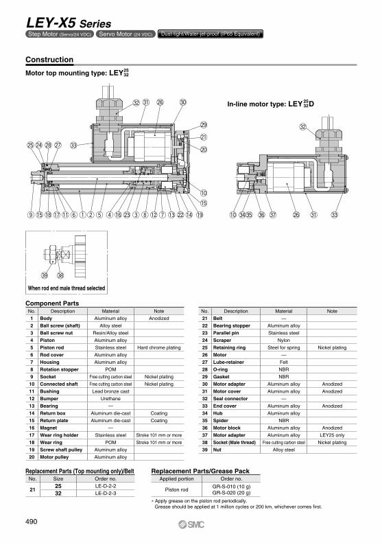
Construction
Motor top mounting type: LEY
Component Parts
In-line motor type: LEY D
2532
2532
Replacement Parts (Top mounting only)/Belt Replacement Parts/Grease Pack
* Apply grease on the piston rod periodically.Grease should be applied at 1 million cycles or 200 km, whichever comes first.
o!5 !8 !7 !1 yqwt r e u!2 !3 !4!6 @3 @2 !0 #4#5 #6 #7 @6 #1
#2
#3
@0
@1
@9
#0@6#1#2
#3@7@8@4@5
!5
!0
i !9
No. Description Material Note
21 Belt —
22 Bearing stopper Aluminum alloy
23 Parallel pin Stainless steel
24 Scraper Nylon
25 Retaining ring Steel for spring Nickel plating
26 Motor —
27 Lube-retainer Felt
28 O-ring NBR
29 Gasket NBR
30 Motor adapter Aluminum alloy Anodized
31 Motor cover Aluminum alloy Anodized
32 Seal connector —
33 End cover Aluminum alloy Anodized
34 Hub Aluminum alloy
35 Spider NBR
36 Motor block Aluminum alloy Anodized
37 Motor adapter Aluminum alloy LEY25 only
38 Socket (Male thread) Free cutting carbon steel Nickel plating
39 Nut Alloy steel
Applied portion Order no.
Piston rodGR-S-010 (10 g)GR-S-020 (20 g)
No. Size Order no.
2125 LE-D-2-2
32 LE-D-2-3
No. Description Material Note
1 Body Aluminum alloy Anodized
2 Ball screw (shaft) Alloy steel
3 Ball screw nut Resin/Alloy steel
4 Piston Aluminum alloy
5 Piston rod Stainless steel Hard chrome plating
6 Rod cover Aluminum alloy
7 Housing Aluminum alloy
8 Rotation stopper POM
9 Socket Free cutting carbon steel Nickel plating
10 Connected shaft Free cutting carbon steel Nickel plating
11 Bushing Lead bronze cast
12 Bumper Urethane
13 Bearing —
14 Return box Aluminum die-cast Coating
15 Return plate Aluminum die-cast Coating
16 Magnet —
17 Wear ring holder Stainless steel Stroke 101 mm or more
18 Wear ring POM Stroke 101 mm or more
19 Screw shaft pulley Aluminum alloy
20 Motor pulley Aluminum alloy
490
LEY-X5 SeriesStep Motor (Servo/24 VDC) Servo Motor (24 VDC) Dust-tight/Water-jet-proof (IP65 Equivalent)
Rod operating range Note 1)
K Note 4)
Actuator cable
H thread depth C
Origin Note 2)
[Stroke end]Strokeend Note 3)
[Origin]
Vent hole Note 5)
4 x O1 thread depth R4 x O1 threaddepth R
XA H9
XB
XA
MH
ML + Stroke (MB)MAMC
MD Section XX
6 x MOthread depth MR
øXA H9 depth XA
T
M
SM
XW
Q
Y
A + Stroke
B + Stroke
Stroke
GV
OA
FV
EV
J
øOB
(GH)
FHEHM
M
øPB
PCL
øD
2
U
PA
[2]
Attach tubing (O.D.: ø4) Note 5)
(Order separately.)
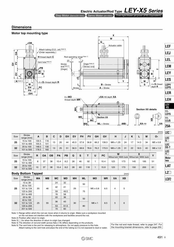
Dimensions
Motor top mounting type
Note 1) Range within which the rod can move when it returns to origin. Make sure a workpiece mounted on the rod does not interfere with the workpieces and facilities around the rod.
Note 2) Position after return to origin.Note 3) [ ] for when the direction of return to origin has changed.Note 4) The direction of rod end width across flats (K) differs depending on the products.Note 5) The vent hole is the port for releasing to atmosphere. Do not apply pressure to this hole.
Attach tubing to the vent hole and place the end of the tubing so it is not exposed to dust or water.
For the rod end male thread, refer to page 247. For the mounting bracket dimensions, refer to page 250.
SizeStroke
range [mm] R OA OB PA PB Q S T U PC W X YWithout lock With lock Without lock With lock
2515 to 100
8 37 38 15.4 8.2 28 46 92 1 15.4 123 173 145 195 51101 to 400
3220 to 100
10 37 38 15.4 8.2 28 60 118 1 15.9 123 173 150 200 61101 to 500
SizeStroke
range [mm] A B C D EH EV FH FV GH GV H J K L M O1
2515 to 100 130.5 116
13 20 44 45.5 57.6 56.8 66.2 139.5 M8 x 1.25 24 17 14.5 34 M5 x 0.8101 to 400 155.5 141
3220 to 100 148.5 130
13 25 51 56.5 69.6 78.6 76.2 173.5 M8 x 1.25 31 22 18.5 40 M6 x 1.0101 to 500 178.5 160
[mm]Body Bottom Tapped
SizeStroke
range [mm] MA MB MC MD MH ML MO MR XA XB
25
15 to 39
20 46
24 32
29
50
M5 x 0.8 6.5 4 540 to 100
42 41101 to 124
75125 to 200 59 49.5201 to 400 76 58
32
20 to 39
25 55
22 36
30
50
M6 x 1 8.5 5 640 to 100
36 43101 to 124
80125 to 200 53 51.5201 to 500 70 60
Section XX details
[mm]
491
Electric Actuator/Rod Type LEY-X5 SeriesStep Motor (Servo/24 VDC) Servo Motor (24 VDC) Dust-tight/Water-jet-proof (IP65 Equivalent)
LEF
LAT
LEJ
LEL
LEY
LEM
LESLEPYLEPS
LEY-X5
LECSLECSS-T
LECYMotor-less
11-LEFS
11-LEJS
LER
LEH
25A-
LEC
LZ
LC3F2
LEY-X5
A

MH
Section XX
MA ML + Stroke
MCMD
U
Vent hole Note 5)
øOB
FHEHM
M
GO
AF
VE
VJ
H thread depth C Rod operating range Note 1)
Origin Note 2)
[Stroke end]Strokeend Note 3)
[Origin]
PC
4 x O1 thread depth R
XA H9
XB
XA
6 x MOthread depth MR
øXA H9 depth XA
K Note 4)
Q
A + Stroke
WB + Stroke
øP
B
YPA
Stroke
LøD
[2] 2
Attach tubing (O.D.: ø4) Note 5)
(Order separately.)
Dimensions
In-line motor type
SizeStroke
range [mm]A B C D EH EV FH FV G H J K L
Without lock With lock
2515 to 100 250 300 89.5
13 20 44 45.5 57.6 57.7 94.7 M8 x 1.25 24 17 14.5101 to 400 275 325 114.5
3220 to 100 265.5 315.5 96
13 25 51 56.5 69.6 79.6 116.6 M8 x 1.25 31 22 18.5101 to 500 295.5 345.5 126
SizeStroke
range [mm] M O1 R OA OB PA PB Q U PC W YWithout lock With lock
2515 to 100
34 M5 x 0.8 8 37 38 15.4 8.2 28 0.9 15.9 146 196 24.5101 to 400
3220 to 100
40 M6 x 1.0 10 37 38 15.4 8.2 28 1 15.9 151 201 27101 to 500
[mm]Body Bottom Tapped
SizeStroke
range [mm] MA MC MD MH ML MO MR XA XB
25
15 to 39
20
24 32
29
50
M5 x 0.8 6.5 4 540 to 100
42 41101 to 124
75125 to 200 59 49.5201 to 400 76 58
32
20 to 39
25
22 36
30
50
M6 x 1 8.5 5 640 to 100
36 43101 to 124
80125 to 200 53 51.5201 to 500 70 60
Section XX details
[mm]
Note 1) Range within which the rod can move when it returns to origin. Make sure a workpiece mounted on the rod does not interfere with the workpieces and facilities around the rod.
Note 2) Position after return to origin.Note 3) [ ] for when the direction of return to origin has changed.Note 4) The direction of rod end width across flats (K) differs depending on the products.Note 5) The vent hole is the port for releasing to atmosphere. Do not apply pressure to this hole.
Attach tubing to the vent hole and place the end of the tubing so it is not exposed to dust or water.
For the rod end male thread, refer to page 247. For the mounting bracket dimensions, refer to page 250.
492
LEY-X5 SeriesStep Motor (Servo/24 VDC) Servo Motor (24 VDC) Dust-tight/Water-jet-proof (IP65 Equivalent)
A

Refer to page 232 for model selection.
How to Order
w Size e Motor mounting position
r Motor type*
* Refer to the applicable stroke table.
y Stroke [mm]
i Rod end thread
u Motor option
* When “With lock” is selected for the top mounting type, the motor body will stick out of the end of the body for size 25 with strokes 30 mm or less. Check for interference with workpieces before selecting a model.
* For motor type S2 and S6, the compatible driver part number suffixes are S1 and S5 respectively.
!0 Cable type*
* The motor and encoder cables are included. (The lock cable is also included when the motor with lock option is selected.)
* Standard cable entry direction is Top mounting: (A) Axis side In-line: (B) Counter axis side(Refer to page 623 for details.)
!1 Cable length [m]*
* The length of the encoder, motor and lock cables are the same.
t Lead [mm]
* The values shown in ( ) are the equivalent lead which includes the pulley ratio for size 32 top mounting type.
!2 Driver type*
* For auto switches, refer to page 507.
* When the driver type is selected, the cable is included. Select cable type and cable length.Example)S2S2: Standard cable (2 m) + Driver (LECSS2)S2 : Standard cable (2 m)Nil : Without cable and driver
o Mounting*1
*1 Mounting bracket is shipped together, (but not assembled).
*2 For horizontal cantilever mounting with the rod flange, head flange and ends tapped, use the actuator within the following stroke range. LEY25: 200 mm or less LEY32: 100 mm or less
*3 Rod flange is not available for the LEY25 with stroke 30 mm and motor option “With lock”.
*4 Head flange is not available for the LEY32.
* Please consult with SMC for non-standard strokes as they are produced as special orders.
* Applicable Stroke Table : Standard
Made to Order: Dust-tight/Water-jet-proofq Accuracy
SB A12S225 100 X5w
LEYe r t
Hq y u i o !0 !1 !2 !3
!3 I/O cable length [m]** When “Without driver” is selected for driver type,
only “Nil: Without cable” can be selected.Refer to page 624 if I/O cable is required.(Options are shown on page 624.)
Motor
Nil Without cableH Without cable (Connector only)1 1.5
Nil Basic typeH High precision type
StrokeModel
30 50 100 150 200 250 300 350 400 450 500 Manufacturablestroke range [mm]
LEY25 — — 15 to 400LEY32 20 to 500
Symbol TypeMotor mounting positionTop mounting In-line
Nil Ends tapped/Body bottom tapped
*2
L Foot —F Rod flange*2 *3 G Head flange*2 *4 —
Compatible driver Power supply voltage [V]Nil Without driver —A1 LECSA1 100 to 120A2 LECSA2 200 to 230B1 LECSB1 100 to 120B2 LECSB2 200 to 230C1 LECSC1 100 to 120C2 LECSC2 200 to 230S1 LECSS1 100 to 120S2 LECSS2 200 to 230
Symbol LEY25 LEY32*A 12 16 (20)B 6 8 (10)C 3 4 (5)
Nil Without cable2 25 5A 10
Nil Without cableS Standard cableR Robotic cable (Flexible cable)
Nil Without optionB With lock*
Nil Rod end female thread
M Rod end male thread(1 rod end nut is included.)
30 30to to
500 500
Symbol TypeOutput
[W]Actuator
sizeCompatible driver
S2 AC servo motor(Incremental encoder)
100 25 LECSA-S1
S3 AC servo motor(Incremental encoder)
200 32 LECSA-S3
S6 AC servo motor(Absolute encoder)
100 25LECSB-S5LECSC-S5LECSS-S5
S7 AC servo motor(Absolute encoder)
200 32LECSB-S7LECSC-S7LECSS-S7
Nil Top mountingD In-line
2532
AC Servo Motor
Electric Actuator/Rod Type Dust-tight/Water-jet-proof (IP65 Equivalent)
LEY-X5 (Made to Order) Series LEY25, 32
494A

Specifications
Weight
[kg]Additional Weight
[kg]Product Weight
Note 1) Please consult with SMC for non-standard strokes as they are produced as special orders.Note 2) The maximum value of the horizontal work load. An external guide is necessary to support the load.
The actual work load changes according to the condition of the external guide. Please confirm using actual device.
Note 3) The force setting range (set values for the driver) for the force control with the torque control mode. Set it with reference to “Force Conversion Graph” on page 236. When the control equivalent to the pushing operation of the controller LECP series is performed, select the LECSS driver and combine it with the Simple Motion (manufactured by Mitsubishi Electric Corporation) which has a pushing operation function.
Note 4) The allowable speed changes according to the stroke. Set the number of rotations according to speed.Note 5) The allowable collision speed for collision with the workpiece with the torque control mode.Note 6) A reference value for correcting an error in reciprocal operation.Note 7) Equivalent lead which includes the pulley ratio [1.25:1]Note 8) Impact resistance: No malfunction occurred when the actuator was tested with a drop tester in both an
axial direction and a perpendicular direction to the lead screw. (Test was performed with the actuator in the initial state.)
Vibration resistance: No malfunction occurred in a test ranging between 45 to 2000 Hz. Test was performed in both an axial direction and a perpendicular direction to the lead screw. (Test was performed with the actuator in the initial state.)
Note 9) Cannot be used in an environment where oil such as cutting oil splashes or it is constantly exposed to water. Take suitable protective measures. For details about enclosure, refer to “Enclosure” on page 306.
Note 10) When mounting vertically and using the product facing upwards in an environment where water is present, take necessary measures to prevent water from splashing on the rod cover, because water will accumulate on the rod seal due to the structure of the product.
Note 11) The power consumption (including the driver) is for when the actuator is operating.Note 12) The standby power consumption when operating (including the driver) is for when the actuator is
stopped in the set position during the operation.Note 13) The maximum instantaneous power consumption (including the driver) is for when the actuator is
operating.Note 14) Only when motor option “With lock” is selected.Note 15) For an actuator with lock, add the power consumption for the lock.
Model LEY25S26 /LEY25DS2
6 LEY32S37 (Top mounting) LEY32DS3
7 (In-line)
Act
uat
or
spec
ifica
tio
ns
Stroke [mm] Note 1) 30, 50, 100, 150, 200250, 300, 350, 400
30, 50, 100, 150, 200, 250300, 350, 400, 450, 500
30, 50, 100, 150, 200, 250300, 350, 400, 450, 500
Work load [kg]Horizontal Note 2) 18 50 50 30 60 60 30 60 60Vertical Note 10) 8 16 30 9 19 37 12 24 46
Force [N] Note 3) (Set value: 15 to 30%) 65 to 131 127 to 255 242 to 485 79 to 157 154 to 308 294 to 588 98 to 197 192 to 385 368 to 736Note 4)
Max. speed[mm/s]
Strokerange
Up to 300 900 450 2251200 600 300 1000 500 250
305 to 400 600 300 150405 to 500 — — — 800 400 200 640 320 160
Pushing speed [mm/s] Note 5) 35 or less 30 or less 30 or lessMax. acceleration/deceleration [mm/s2] 5000 5000Positioning repeatability [mm]
Basic type ±0.02High precision type ±0.01
Lost motion [mm] Note 6) Basic type 0.1 or lessHigh precision type 0.05 or less
Lead [mm] 12 6 3 20 Note 7) 10 Note 7) 5 Note 7) 16 8 4Impact/Vibration resistance [m/s2] Note 8) 50/20 50/20Actuation type Ball screw + Belt/Ball screw Ball screw + Belt Ball screwGuide type Sliding bushing (Piston rod) Sliding bushing (Piston rod)Enclosure Note 9) IP65 equivalentOperating temperature range [°C] 5 to 40 5 to 40Operating humidity range [%RH] 90 or less (No condensation) 90 or less (No condensation)Regeneration option May be required depending on speed and work load. (Refer to pages 234 and 235.)
Ele
ctri
c sp
ecifi
cati
on
s Motor output/Size 100 W/40 200 W/60Motor type AC servo motor (100/200 VAC) AC servo motor (100/200 VAC)
Encoder Motor type S2, S3: Incremental 17-bit encoder (Resolution: 131072 p/rev)Motor type S6, S7: Absolute/incremental dual 18-bit encoder (Resolution: 262144 p/rev)
Power consumption [W] Note 11)
Horizontal 45 65 65Vertical 145 175 175
Standby power consumptionwhen operating [W] Note 12)
Horizontal 2 2 2Vertical 8 8 8
Max. instantaneous power consumption [W] Note 13) 445 724 724
Lock
uni
tsp
ecifi
catio
ns Type Note 14) Non-magnetizing lockHolding force [N] 131 255 485 157 308 588 197 385 736Power consumption [W] at 20°C Note 15) 6.3 7.9 7.9Rated voltage [V] 24 VDC 0-10%
Series LEY25DS (Motor mounting position: In-line) LEY32DS (Motor mounting position: In-line)Stroke [mm] 30 50 100 150 200 250 300 350 400 30 50 100 150 200 250 300 350 400 450 500
Mot
orty
pe Incremental encoder 1.34 1.41 1.58 1.84 2.02 2.19 2.37 2.54 2.72 2.44 2.55 2.84 3.31 3.59 3.87 4.16 4.44 4.72 5.00 5.28Absolute encoder 1.40 1.47 1.64 1.90 2.08 2.25 2.43 2.60 2.78 2.38 2.49 2.78 3.25 3.53 3.81 4.10 4.38 4.66 4.94 5.22
Series LEY25S (Motor mounting position: Top mounting) LEY32S (Motor mounting position: Top mounting)Stroke [mm] 30 50 100 150 200 250 300 350 400 30 50 100 150 200 250 300 350 400 450 500
Mot
orty
pe Incremental encoder 1.31 1.38 1.55 1.81 1.99 2.16 2.34 2.51 2.69 2.42 2.53 2.82 3.29 3.57 3.85 4.14 4.42 4.70 4.98 5.26Absolute encoder 1.37 1.44 1.61 1.87 2.05 2.22 2.40 2.57 2.75 2.36 2.47 2.76 3.23 3.51 3.79 4.08 4.36 4.64 4.92 5.20
Size 25 32
LockIncremental encoder 0.20 0.40Absolute encoder 0.30 0.66
Rod end male threadMale thread 0.03 0.03Nut 0.02 0.02
Foot (2 sets including mounting bolt) 0.08 0.14Rod flange (including mounting bolt)
0.17 0.20Head flange (including mounting bolt)
495
Electric Actuator/Rod Type LEY-X5 SeriesAC Servo Motor Dust-tight/Water-jet-proof (IP65 Equivalent)
LEF
LAT
LEJ
LEL
LEY
LEM
LESLEPYLEPS
LEY-X5
LECSLECSS-T
LECYMotor-less
11-LEFS
11-LEJS
LER
LEH
25A-
LEC
LZ
LC3F2
LEY-X5
A

When rod end male thread selected
#6 #5
Construction
Motor top mounting type: LEY
Component Parts
In-line motor type: LEY D2532 25
32
Replacement Parts (Top mounting only)/Belt Replacement Parts/Grease Pack
* Apply grease on the piston rod periodically.Grease should be applied at 1 million cycles or 200 km, whichever comes first.
Cable is shipped together.
o !7 !8 y t q w eri u@2
!9
@1
@0
!2 !3 !4 !0 #3 #4 #3 #2 #1 @7
#0#1 @6@7
@3@4@5 !1@8@9
!5
!0
!6
Applied portion Order no.
Piston rodGR-S-010 (10 g)GR-S-020 (20 g)
No. Size Order no.
2125 LE-D-2-2
32 LE-D-2-4
No. Description Material Note
19 Screw shaft pulley Aluminum alloy
20 Motor pulley Aluminum alloy
21 Belt —
22 Bearing stopper Aluminum alloy
23 Parallel pin Stainless steel
24 Scraper Nylon
25 Retaining ring Steel for spring Nickel plating
26 Motor adapter Aluminum alloy Coating
27 Motor —
28 Lube-retainer Felt
29 O-ring NBR
30 Gasket NBR
31 O-ring NBR
32 Motor block Aluminum alloy Coating
33 Hub Aluminum alloy
34 Spider Urethane
35 Socket (Male thread) Free cutting carbon steel Nickel plating
36 Nut Alloy steel Zinc chromated
No. Description Material Note
1 Body Aluminum alloy Anodized
2 Ball screw (shaft) Alloy steel
3 Ball screw nut Resin/Alloy steel
4 Piston Aluminum alloy
5 Piston rod Stainless steel Hard chrome plating
6 Rod cover Aluminum alloy
7 Housing Aluminum alloy
8 Rotation stopper POM
9 Socket Free cutting carbon steel Nickel plating
10 Connected shaft Free cutting carbon steel Nickel plating
11 Bushing Lead bronze cast
12 Bumper Urethane
13 Bearing —
14 Return box Aluminum die-cast Coating
15 Return plate Aluminum die-cast Coating
16 Magnet —
17 Wear ring holder Stainless steel Stroke 101 mm or more
18 Wear ring POM Stroke 101 mm or more
496
LEY-X5 SeriesAC Servo Motor Dust-tight/Water-jet-proof (IP65 Equivalent)

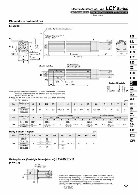
K Note 2) 4 x O1 thread depth R
Vent hole Note 3)
H thread depth C
4 x O1 thread depth R
Encoder Z-phase detecting position
Rod operating range Note 1)
(Stroke + 4 mm)
2 ± 1
øD
V
EV
J
MEH PC
MPA
øPB
A + Stroke
B + Stroke
Y
L SM
TZ
M
U
XW
Attach tubing (O.D.: ø4) Note 3)
(Order separately.)
MH
Section XX
MA ML + Stroke
MCMD
XA H9
XB
XA
6 x MOthread depth MR
(MB)
øXA H9 depth XA
Dimensions
Motor top mounting type: LEY25 32
SizeStroke
range [mm] S T U PCIncremental encoder Absolute encoder
YWithout lock With lock Without lock With lockW X Z W X Z W X Z W X Z
2515 to 100
46 92 1 15.4 87 120 14.1 123.9 156.9 15.8 82.4 115.4 14.1 123.5 156.5 15.8 51101 to 400
3220 to 100
60 118 1 15.9 88.2 128.2 17.1 116.8 156.8 17.1 76.6 116.6 17.1 116.1 156.1 17.1 61101 to 500
SizeStroke
range [mm] A B C D EH EV H J K L M O1 R PA PB V
2515 to 100 130.5 116
13 20 44 45.5 M8 x 1.25 24 17 14.5 34 M5 x 0.8 8 15.4 8.2 40101 to 400 155.5 141
3220 to 100 148.5 130
13 25 51 56.5 M8 x 1.25 31 22 18.5 40 M6 x 1.0 10 15.4 8.2 60101 to 500 178.5 160
[mm]
[mm]
Body Bottom Tapped
SizeStroke
range [mm] MA MB MC MD MH ML MO MR XA XB
25
15 to 39
20 46
24 32
29
50
M5 x 0.8 6.5 4 540 to 100
42 41101 to 124
75125 to 200 59 49.5201 to 400 76 58
32
20 to 39
25 55
22 36
30
50
M6 x 1 8.5 5 640 to 100
36 43101 to 124
80125 to 200 53 51.5201 to 500 70 60
Section XX details
Note 1) Range within which the rod can move. Make sure a workpiece mounted on the rod does not interfere with the workpieces and facilities around the rod.
Note 2) The direction of rod end width across flats (mK) differs depending on the products.Note 3) The vent hole is the port for releasing to atmosphere. Do not apply pressure to this hole.
Attach tubing to the vent hole and place the end of the tubing so it is not exposed to dust or water.
For the rod end male thread, refer to page 261. For the mounting bracket dimensions, refer to page 250.
497
Electric Actuator/Rod Type LEY-X5 SeriesAC Servo Motor Dust-tight/Water-jet-proof (IP65 Equivalent)
LEF
LAT
LEJ
LEL
LEY
LEM
LESLEPYLEPS
LEY-X5
LECSLECSS-T
LECYMotor-less
11-LEFS
11-LEJS
LER
LEH
25A-
LEC
LZ
LC3F2
LEY-X5
A

MH
Section XX
MA ML + Stroke
MCMD
JPC
EV
ZT
SEHM
M
U
R4 x O1 thread depth R
H thread depth C
Encoder Z-phase detecting position
Rod operating range Note 1)
(Stroke + 4 mm)
2 ± 1
Vent hole Note 3)
XA H9
XB
XA
6 x MOthread depth MR
øXA H9 depth XA
K Note 2)
øD
WA + Stroke
B + Stroke
Y
L
øP
B
PAAttach tubing (O.D.: ø4) Note 3)
(Order separately.)
Dimensions
SizeStroke
range [mm] H J K L M O1 R PA PB V S T U PC Y
2515 to 100
M8 x 1.25 24 17 14.5 34 M5 x 0.8 8 15.4 8.2 40 45 46.5 1.5 15.9 71.5101 to 400
3220 to 100
M8 x 1.25 31 22 18.5 40 M6 x 1.0 10 15.4 8.2 60 60 61 1 15.9 87101 to 500
SizeStroke
range [mm]
Incremental encoder Absolute encoderB C D EH EVWithout lock With lock Without lock With lock
A W Z A W Z A W Z A W Z
2515 to 100 238
87 14.6274.9
123.9 16.3233.4
82.4 14.6274.5
123.5 16.3136.5
13 20 44 45.5101 to 400 263 299.9 258.4 299.5 161.5
3220 to 100 262.7
88.2 17.1291.3
116.8 17.1251.1
76.6 17.1290.6
116.1 17.1156
13 25 51 56.5101 to 500 292.7 321.3 281.1 320.6 186
[mm]
[mm]
Body Bottom Tapped
SizeStroke
range [mm] MA MC MD MH ML MO MR XA XB
25
15 to 39
20
24 32
29
50
M5 x 0.8 6.5 4 540 to 100
42 41101 to 124
75125 to 200 59 49.5201 to 400 76 58
32
20 to 39
25
22 36
30
50
M6 x 1 8.5 5 640 to 100
36 43101 to 124
80125 to 200 53 51.5201 to 500 70 60
Section XX details
Note 1) Range within which the rod can move. Make sure a workpiece mounted on the rod does not interfere with the workpieces and facilities around the rod.
Note 2) The direction of rod end width across flats (mK) differs depending on the products.Note 3) The vent hole is the port for releasing to atmosphere. Do not apply pressure to this hole.
Attach tubing to the vent hole and place the end of the tubing so it is not exposed to dust or water.
For the rod end male thread, refer to page 261. For the mounting bracket dimensions, refer to page 250.
In-line motor type: LEY25 32D
498
LEY-X5 SeriesAC Servo Motor Dust-tight/Water-jet-proof (IP65 Equivalent)
A

w y !0i oe r tq u !1 !2 !3 !4
Refer to page 232 for model selection.
y Stroke [mm]
!0 Mounting*1 !1 Cable type Note 1)
!2 Cable length Note 2) [m]
u Dust/Drip proof i Motor option o Rod end thread
r Motor type t Lead [mm]
*1 Mounting bracket is shipped together, (but not assembled).
*2 For horizontal cantilever mounting with the rod flange and ends tapped, use the actuator within the following stroke range.• LEY63: 400 mm or less
*3 For mounting with the double clevis, use the actuator within the following stroke range.• LEY63: 300 mm or less
Note 1) The motor and encoder cables are included. (The lock cable is also included when the motor with lock option is selected.)
* Standard cable entry direction is • Top/Parallel: (A) Axis side • In-line: (B) Counter axis side (Refer to page 623 for details.)
* When the driver type is selected, the cable is included. Select cable type and cable length.Example) S2S2 : Standard cable (2 m) + Driver (LECSS2)S2 : Standard cable (2 m) Nil : Without cable and driver
* When using the dust-tight/water-jet-proof (IP65 equivalent), correctly mount the fitting and tubing to the vent hole tap, and then place the end of the tubing in an area not exposed to dust or water.
* The fitting and tubing should be provided separately by the customer. Select [Applicable tubing O.D.: ø4 or more, Connection thread: Rc1/8].
* Cannot be used in an environment where oil such as cutting oil splashes or it is constantly exposed to water. Take suitable protective measures. For details about enclosure, refer to “Enclosure” on page 306.
* Screw lead 5 mm, Pulley ratio [4:7] equivalent lead
* Only available for top mounting and right/left side parallel types.
Note 2) The length of the encoder, motor and lock cables are the same.
* Applicable stroke table
Note) Please consult with SMC for non-standard strokes as they are produced as special orders.
Symbol TypeOutput
[W]Actuator
sizeCompatible
driver
S4 AC servo motor(Incremental encoder)
400 63 LECSA2-S4
S8 AC servo motor(Absolute encoder)
400 63LECSB2-S8LECSC2-S8LECSS2-S8
!3 Driver typeCompatible driver Power supply voltage
Nil Without driver
A2 LECSA2/Pulse input(Incremental encoder)
200 V to 230 V
B2 LECSB2/Pulse input(Absolute encoder)
200 V to 230 V
C2 LECSC2/CC-Link(Absolute encoder)
200 V to 230 V
S2 LECSS2/SSCNET#(Absolute encoder)
200 V to 230 V
Stroke[mm]
Model100 200 300 400 500 600 700 800 Manufacturable
stroke range
LEY63 50 to 800
Nil Without cable
2 2
5 5
A 10
Nil Without cable
S Standard cable
R Robotic cable (Flexible cable)
Symbol TypeMotor mounting position
Top/Parallel In-line
Nil Ends tapped/Body bottom tapped
*2
L Foot —
F Rod flange*2 D Double clevis*3 —
100 100
to to
800 800
Symbol LEY63A 20
B 10
C 5
L 2.86*
Nil Rod end female thread
M Rod end male thread(1 rod end nut is included.)
Nil IP5x equivalent (Dust-protected)
P IP65 equivalent (Dust-tight/Water-jet-proof)/ With vent hole tap
Nil Without option
B With lock
e Motor mounting positionNil Top mounting
R Right side parallel
L Left side parallel
D In-line
S 2B PH S4 200LEY 63 A2
q AccuracyNil Basic type
H High precision type
w Size63
!4 I/O cable length [m]*
Nil Without cable
H Without cable (Connector only)
1 1.5
* When “Without driver” is selected for driver type, only “Nil: Without cable” can be selected.Refer to page 624 if I/O cable is required.(Options are shown on page 624.)
AC Servo Motor
Electric Actuator/Rod Type Dust-tight/Water-jet-proof (IP65 Equivalent)
LEY Series LEY63
How to Order
* Select options
500A

Product Weight Additional Weight [kg] [kg]
Note 1) Please consult with SMC for non-standard strokes as they are produced as special orders.Note 2) The maximum value of the horizontal work load. An external guide is necessary to support the load. The actual work load changes according to the
condition of the external guide. Please confirm using actual device.Note 3) Set values for the driver.Note 4) The force setting range (set values for the driver) for the force control with the torque control mode. The pushing force and duty ratio change
according to the set value. Set it with reference to “Force Conversion Graph” on page 236. When the control equivalent to the pushing operation of the controller LECP series is performed, select the LECSS driver and combine it with the Simple Motion (manufactured by Mitsubishi Electric Corporation) which has a pushing operation function.
Note 5) The allowable speed changes according to the stroke. Set the number of rotations according to speed.Note 6) The allowable collision speed for collision with the workpiece with the torque control mode.Note 7) A reference value for correcting an error in reciprocal operation. Note 8) Impact resistance: No malfunction occurred when the actuator was tested with a drop tester in both an axial direction and a perpendicular direction
to the lead screw. (Test was performed with the actuator in the initial state.)Vibration resistance: No malfunction occurred in a test ranging between 45 to 2000 Hz. Test was performed in both an axial direction and a
perpendicular direction to the lead screw. (Test was performed with the actuator in the initial state.)Note 9) When mounting vertically and using the product facing upwards in an environment where water is present, take necessary measures to prevent
water from splashing on the rod cover, because water will accumulate on the rod seal due to the structure of the product.Note 10) The power consumption (including the driver) is for when the actuator is operating.Note 11) The standby power consumption when operating (including the driver) is for when the actuator is stopped in the set position during the operation.Note 12) The maximum instantaneous power consumption (including the driver) is for when the actuator is operating.Note 13) Only when motor option “With lock” is selected.Note 14) For an actuator with lock, add the power consumption for the lock.
Model LEY63S48 (Top/Parallel) LEY63DS4
8 (In-line)
Act
uat
or
spec
ifica
tio
ns
Stroke [mm] Note 1) 100, 200, 300, 400, 500, 600, 700, 800
Work load [kg]Horizontal Note 2) 40 70 80 200 40 70 80Vertical Note 9) 19 38 72 115 19 38 72
Force [N]/Set value Note 3) : 15 to 50% Note 4) 156 to 521 304 to 1012 573 to 1910 1003 to 3343 156 to 521 304 to 1012 573 to 1910
Note 5)Max. speed[mm/s]
Strokerange
Up to 500 1000 500 250
70
1000 500 250505 to 600 800 400 200 800 400 200605 to 700 600 300 150 600 300 150705 to 800 500 250 125 500 250 125
Pushing speed [mm/s] Note 6) 30 or lessMax. acceleration/deceleration [mm/s2] 5000 3000 5000Positioning repeatability [mm]
Basic type ±0.02High precision type ±0.01
Lost motion [mm] Note 7) Basic type 0.1 or lessHigh precision type 0.05 or less
Screw lead [mm] (including pulley ratio) 20 10 5 5 (2.86) 20 10 5Impact/Vibration resistance [m/s2] Note 8) 50/20Actuation type Ball screw Ball screw + Belt [Pulley ratio 4:7] Ball screwGuide type Sliding bushing (Piston rod)Operating temperature range [°C] 5 to 40Operating humidity range [%RH] 90 or less (No condensation)Regeneration option May be required depending on speed and work load. (Refer to pages 234 and 235.)
Ele
ctri
c sp
ecifi
cati
on
s Motor output/Size 400 W/60Motor type AC servo motor (200 VAC)
Encoder Motor type S4: Incremental 17-bit encoder (Resolution: 131072 p/rev) Motor type S8: Absolute 18-bit encoder (Resolution: 262144 p/rev)
Power consumption [W] Note 10) Horizontal 210Vertical 230
Standby power consumptionwhen operating [W] Note 11)
Horizontal 2Vertical 18
Max. instantaneous power consumption [W] Note 12) 1275
Lo
ck u
nit
sp
ecifi
cati
on
s Type Note 13) Non-magnetizing lockHolding force [N] 313 607 1146 2006 313 607 1146Power consumption [W] at 20°C Note 14) 7.9Rated voltage [V] 24 VDC 0
−10%
Size 63
LockIncremental encoder 0.4Absolute encoder 0.6
Rod end male thread
Male thread 0.12Nut 0.04
Foot (2 sets including mounting bolt) 0.26Rod flange (including mounting bolt) 0.51Double clevis (including pin, retaining ring and mounting bolt) 0.58
Series LEY63S (Motor mounting position: Top/Parallel)Stroke [mm] 100 200 300 400 500 600 700 800
Mot
or ty
pe Incrementalencoder 5.4 6.6 8.3 9.4 10.5 12.2 13.4 14.5
Absoluteencoder 5.5 6.7 8.4 9.5 10.6 12.3 13.5 14.6
Series LEY63DS (Motor mounting position: In-line)Stroke [mm] 100 200 300 400 500 600 700 800
Mot
or ty
pe Incrementalencoder 5.6 6.7 8.4 9.6 10.7 12.4 13.5 14.7
Absoluteencoder 5.7 6.8 8.5 9.7 10.8 12.5 13.6 14.8
Specifications
Weight
501
Electric Actuator/Rod Type LEY SeriesAC Servo Motor Dust-tight/Water-jet-proof (IP65 Equivalent)
* Select options
LEF
LAT
LEJ
LEL
LEY
LEM
LESLEPYLEPS
LEY-X5
LECSLECSS-T
LECYMotor-less
11-LEFS
11-LEJS
LER
LEH
25A-
LEC
LZ
LC3F2
LEY-X5
A

Cable is shipped together.
@9 @9#0
@7@8
@4
y
o
q reiu @0!6 !5 !4 !1 !2
!7
wt
!3
!0 @8!9
!8
@3@4
@1@2
@5@6
When rod end male thread selected
Component PartsNo. Description Material Note
1 Body Aluminum alloy Anodized
2 Ball screw shaft Alloy steel
3 Ball screw nut Resin/Alloy steel
4 Piston Aluminum alloy
5 Piston rod Stainless steel Hard chrome plating
6 Rod cover Aluminum alloy
7 Bearing holder Aluminum alloy
8 Rotation stopper Resin
9 Socket Free cutting carbon steel Nickel plating
10 Bushing Lead bronze cast
11 Bearing —
12 Return box Aluminum alloy Coating
13 Return plate Aluminum alloy Coating
14 Magnet —
15 Wear ring holder Stainless steel
No. Description Material Note
16 Wear ring Resin
17 Screw shaft pulley Aluminum alloy
18 Motor pulley Aluminum alloy
19 Belt —
20 Lock nut Alloy steel Black dyed
21 Seal NBR
22 Retaining ring Steel for spring
23 Motor adapter Aluminum alloy Coating
24 Motor —
25 Socket (Male thread) Free cutting carbon steel Nickel plating
26 Nut Alloy steel Trivalent chromated
27 Motor block Aluminum alloy Coating
28 Spacer A Stainless steel
29 Hub Aluminum alloy
30 Spider Urethane
Replacement Parts (Top/Parallel only)/BeltNo. Size Lead Order no.
19 63A/B/C LE-D-2-5
L LE-D-2-6
Construction
Motor top mounting type: LEY63
In-line motor type: LEY63D
Replacement Parts/Grease PackApplied portion Order no.
Piston rodGR-S-010 (10 g)GR-S-020 (20 g)
* Apply grease on the piston rod periodically.Grease should be applied at 1 million cycles or 200 km, whichever comes first.
502
LEY SeriesAC Servo Motor Dust-tight/Water-jet-proof (IP65 Equivalent)
* Select options

Rc1/8Vent hole tap∗
18
ZZ
ZT
UM
SM
4 x O1
thread depth RA + Stroke
B + Stroke
YL
XW
Encoder Z-phase detecting position
4±1
Rod operating range
(Stroke + 8 mm)
øD
EV
V
J
EHM
4 x O1
thread depth R
M
H x 2thread depth C
K Note 2)
Note 1)
Section XX details
ML + Stroke
Section XXMCMA
øXA H9 depth XA6 x MOthread depth MR
MH
MD
XAXBXA H9
IP65 equivalent (Dust-tight/Water-jet-proof): LEY63-P(View ZZ)
* When using the dust-tight/water-jet-proof (IP65 equivalent), correctly mount the fitting and tubing to the vent hole tap, and then place the end of the tubing in an area not exposed to dust or water. The fitting and tubing should be provided separately by the customer.Select [Applicable tubing O.D.: ø4 or more, Connection thread: Rc1/8].
[mm]
SizeStroke range
[mm] MA MC MD MH ML MO MR XA XB
63
50 to 74
38
24 50
4465
M8 x 1.25 10 6 775 to 124 45 60.5125 to 200 58 67201 to 500
86 81100
501 to 800 135
Body Bottom Tapped
Dimensions: Motor Top/Parallel
[mm]
SizeStroke range
[mm] A B C D EH EV H J K L M O1 R S Y
63 Up to 200 192.6 155.2
21 40 76 82 M16 x 2 44 36 37.4 60 M8 x 1.25 16 80 32.2205 to 500 227.6 190.2505 to 800 262.6 225.2
SizeStroke range
[mm] T U VIncremental encoder Absolute encoder
Without lock With lock Without lock With lockW X Z W X Z W X Z W X Z
63 Up to 200
146 4 60 110.2 150.215.6
(16.6)* 138.8 178.815.6
(16.6)* 98.5 138.515.6
(16.6)* 138 17815.6
(16.6)*205 to 500505 to 800
Note 1) Range within which the rod can move.Make sure a workpiece mounted on the rod does not interfere with the workpieces and facilities around the rod.
Note 2) The direction of rod end width across flats (K) differs depending on the products.
* The values in ( ) are the dimensions when L is selected for screw lead.
503
Electric Actuator/Rod Type LEY SeriesAC Servo Motor Dust-tight/Water-jet-proof (IP65 Equivalent)
* Select options
LEF
LAT
LEJ
LEL
LEY
LEM
LESLEPYLEPS
LEY-X5
LECSLECSS-T
LECYMotor-less
11-LEFS
11-LEJS
LER
LEH
25A-
LEC
LZ
LC3F2
LEY-X5

T2
S1
U
S1
T2 U
Note) When the motor is mounted on the left or right side in parallel, the groove for auto switch on the side to which the motor is mounted is hidden.
[mm]
Size S1 T2 U63 84 142 4
Motor left side parallel type: LEY63L Motor right side parallel type: LEY63R
Dimensions: Motor Top/Parallel
504
LEY SeriesAC Servo Motor Dust-tight/Water-jet-proof (IP65 Equivalent)
* Select options
10.5
50
Rc1/8Vent hole tap∗
UVWB + Stroke
A + Stroke
Rod operating range Note 1)
(Stroke + 8 mm)
4±1
L
M
K Note 2)
MEHS
JE
VTZ
H thread effective depth C
4 x O1 thread effective depth R
Encoder Z-phase detecting position
øD
ZZ
Section XX details
MH
6 x MO threadeffective depth MRøXA H9 depth XA
XAXBXA H9
MAMC
ML + Stroke
MDSection XX
LEY63D
IP65 equivalent (Dust-tight/Water-jet-proof): LEY63D-P
Note 1) Range within which the rod can move. Make sure a workpiece mounted on the rod does not interfere with the workpieces and facilities around the rod.
Note 2) The direction of rod end width across flats (K) differs depending on the products. [mm]
* When using the dust-tight/water-jet-proof (IP65 equivalent), correctly mount the fitting and tubing to the vent hole tap, and then place the end of the tubing in an area not exposed to dust or water. The fitting and tubing should be provided separately by the customer.Select [Applicable tubing O.D.: ø4 or more, Connection thread: Rc1/8].
SizeStroke range
[mm] C D EH EV H J K L M O1 R S T U
63 Up to 200
21 40 76 82 M16 x 2 44 36 37.4 60 M8 x 1.25 16 78 83 5205 to 500505 to 800
SizeStroke range
[mm] B VIncremental encoder Absolute encoder
Without lock With lock Without lock With lockA W Z A W Z A W Z A W Z
63Up to 200 190.7
60338.3
110.2 8.1366.9
138.8 8.1326.6
98.5 8.1366.1
138 8.1205 to 500 225.7 373.3 401.9 361.6 401.1505 to 800 260.7 408.3 436.9 396.6 436.1
(View ZZ)
[mm]
SizeStroke range
[mm] MA MC MD MH ML MO MR XA XB
63
50 to 74
38
24 50
4465
M8 x 1.25 10 6 775 to 124 45 60.5
125 to 200 58 67201 to 500
86 81100
501 to 800 135
Body Bottom Tapped
Dimensions: In-line Motor
505
Electric Actuator/Rod Type LEY SeriesAC Servo Motor Dust-tight/Water-jet-proof (IP65 Equivalent)
* Select options
LEF
LAT
LEJ
LEL
LEY
LEM
LESLEPYLEPS
LEY-X5
LECSLECSS-T
LECYMotor-less
11-LEFS
11-LEJS
LER
LEH
25A-
LEC
LZ
LC3F2
LEY-X5

M18
x 1
.5
76.4∗39
26
Width across flats 27 11
Outward mounting
110
95
88
50
4 x ø9
LA + StrokeLS + Stroke
84.3
3.2
29.2
3.2
5 5
25.2
814.2
LS + Stroke
28.4∗
9
108
92
60 80
4 x ø9
DA + StrokeCL + Stroke
1430
22
ø14 hole H10axis d9
8
37.4 −0.144−0.3
+0.422+0.2
End male thread: LEY63-M
* The measurement 76.4 is when the unit is in the Z-phase detecting position. At this position, 4 mm from the end of the operating range.
Included parts• Flange• Body mounting bolt
Included parts• Foot• Body mounting bolt
Included parts• Double clevis• Body mounting bolt• Clevis pin• Retaining ring
Material: Carbon steel (Chromate treated)
* The overall length is when the unit is in the Z-phase detecting position. At this position, 4 mm from the end of the operating range.
Note) When the motor mounting is the right or left side paralleltype, the head side foot should be mounted outwards.
Rod flange: LEY63-F
Foot: LEY63-L
Double clevis: LEY63-D
Dimensions
[mm]Stroke range [mm] LA LS
50 to 200 200.8 133.2201 to 500 235.8 168.2501 to 800 270.8 203.2
[mm]Stroke range [mm] DA CL
50 to 200 236.6 222.6201 to 500 271.6 257.6501 to 800 306.6 292.6
Material: Carbon steel (Nickel plating)* When the unit is in the Z-phase detecting
position. At this position, 4 mm from the end of the operating range.
Material: Cast iron (Coating)* The overall length is when the unit is in the Z-phase detecting
position. At this position, 4 mm from the end of the operating range.
506
LEY SeriesAC Servo Motor Dust-tight/Water-jet-proof (IP65 Equivalent)
* Select options

Indicator lightSlotted set screw (flat point)Mounting screw M2.5 x 4 L Stainless steel
2
2.8
0.2
3
24
500(1000)(3000)(5000)
ø2.
66 Most sensitive position
Indicator lightSlotted set screwM2.5 x 4 L
2
42.
8 22
83.2 4.
6
9.3
4
4 4
2.6
6 Most sensitive position
2.7
Indicator lightSlotted set screw (flat point)Mounting screw M2.5 x 4 L Stainless steel
2
2.8
22
8
4.6
ø2.6
9.3 2.
6
6 Most sensitive position
ø2.6
500(
1000
)(30
00)(
5000
)
SMC
SMC
Note 1) Refer to Best Pneumatics No. 2-1 for solid state auto switch common specifications.Note 2) Refer to Best Pneumatics No. 2-1 for lead wire lengths.
Grommet
Water (coolant) resistant type 2-wire load current is reduced
(2.5 to 40 mA). The proper operating range can
be determined by the color of the light. (Red → Green ← Red)
Using flexible cable as standard spec.
RoHS
2 cores (Brown/Blue)
0.88
17
Auto switch model D-M9NA D-M9NAV D-M9PA D-M9PAV D-M9BA D-M9BAV
3 cores (Brown/Blue/Black)
Sheath
Insulator
Conductor
Outside diameter [mm]
Number of cores
Outside diameter [mm]
Effective area [mm2]
Strand diameter [mm]
Minimum bending radius [mm] (Reference values)
2.6
0.88
17
2.7 x 3.2 (ellipse)
0.9
20
2.6
0.88
17
2.7 x 3.2 (ellipse)
0.9
20
0.15
0.05
2.6 2.6
Oilproof Flexible Heavy-duty Lead Wire Specifications
Water Resistant 2-Color IndicatorSolid State Auto Switch: Direct Mounting TypeD-M9NA(V)/D-M9PA(V)/D-M9BA(V)
PrecautionsCaution
Fix the auto switch with the existing screw installed on the auto switch body. The auto switch may be damaged if a screw other than the one supplied is used.Please consult with SMC if using coolantliquid other than water based solution.
Auto switch model
Electrical entry direction
Wiring type
Output type
Applicable load
Power supply voltage
Current consumption
Load voltage
Load current
Internal voltage drop
Leakage current
Indicator light
Standard
D-M9NAVD-M9NA D-M9BA D-M9BAV
2-wire
—
24 VDC relay, PLC
—
—
24 VDC (10 to 28 VDC)
2.5 to 40 mA
4 V or less
0.8 mA or less
D-M9PAVD-M9PA
Operating range .......... Red LED illuminates.Proper operating range .......... Green LED illuminates.
3-wire
IC circuit, Relay, PLC
5, 12, 24 VDC (4.5 to 28 V)
10 mA or less
40 mA or less
0.8 V or less at 10 mA (2 V or less at 40 mA)
100 µA or less at 24 VDC
In-line Perpendicular In-line Perpendicular In-line Perpendicular
NPN PNP
CE marking, RoHS
28 VDC or less —
D-M9A, D-M9AV (With indicator light)
Auto Switch SpecificationsPLC: Programmable Logic Controller
Weight (g)
Auto switch model0.5 m (Nil)
1 m (M)3 m (L)5 m (Z)
D-M9NA(V)8
144168
D-M9PA(V) D-M9BA(V)7
133863
Leadwire
length
Dimensions
D-M9A
D-M9NAV/D-M9PAV D-M9BAV
(mm)
507
LEF
LAT
LEJ
LEL
LEY
LEM
LESLEPYLEPS
LEY-X5
LECSLECSS-T
LECYMotor-less
11-LEFS
11-LEJS
LER
LEH
25A-
LEC
LZ
LC3F2
LEY-X5
A