environmental management plan gas collection … · 1.4 overview of qgc’s environmental...
TRANSCRIPT

Environmental Management Plan Gas Collection Header Pipeline
QCLNG- BG00-ENV-PLN-000002
Rev 3
December 2011
Uncontrolled when printed
QCLNG PROJECT

Environmental Management Plan Gas Collection Header Pipeline
Revision 3 – December 2011 QCLNG- BG00-ENV-PLN-000002
2 of 89
DOCUMENT INFORMATION SHEET
TITLE: QCLNG Gas Collection Header Environmental Management Plan
PURPOSE AND SCOPE: The purpose of this document is to describe the environmental values and factors that may be impacted on by the development of the QCLNG Project’s Gas Collection Header that will transmit gas from the QCLNG Central Processing Plants to the Export Pipeline.
It applies to all staff, contractors and sub-contractors involved in the design, construction and operation of this pipeline, as described in this EMP.
Revision Record
Issue Date Reason for Issue Responsible Accountable
1 19th May 2010 For supporting information to the EA application for the Gas Collection Header
P. Jacob M. Harris
2 16th May 2011 Revised with SEWPC comments B. French A. Wharton
3 15th December 2011
Revised in line with SEWPC RFI (File Ref 2011/00941)
B. French J. MacDermott

Environmental Management Plan Gas Collection Header Pipeline
Revision 3 – December 2011 QCLNG- BG00-ENV-PLN-000002
3 of 89
Table of Contents
1.0 INTRODUCTION 5
1.1 The QCLNG Project 5
1.2 Scope Of The Environmental Management Plan 6
1.3 Company Structure 6
1.4 Overview of QGC’s Environmental Management Policy 6
1.5 QGC Environmental Management Structure and Responsibilities 8
1.6 BG and QGC’s compliance record 11
1.7 Overview of Legislation 11
1.8 The Pipeline Licence Application for the Gas Collection Header 11
2.0 DESCRIPTION OF PETROLEUM TENURES / PETROLEUM AUTHOR ITIES 11
2.1 Description of Area 16
3.0 DESCRIPTION OF PROJECT ACTIVITIES 17
3.1 Gas Collection Header Pipeline Specifications 17
3.2 Design Parameters 17
3.3 Cathodic Protection 19
3.4 Corridor Widths and Access 20
3.5 Design Criteria for Temporary or Permanent Access Crossings 23
3.6 Watercourse Crossings 23
3.7 Timeframe And Staging 24
3.8 Environmentally Relevant Activities 25
3.9 Notifiable Activities 25
4.0 FINANCIAL ASSURANCE 25
5.0 STRUCTURE OF ENVIRONMENTAL MANAGEMENT 28
5.1 Environmental Factors 28
5.2 Environmental Objectives And Performance Criteria 29
6.0 ENVIRONMENTAL MANAGEMENT PLANS 33
6.1 Noise And Vibration 33
6.2 Air Quality and Dust 35
6.3 Climate Extremes And Climate Change 38
6.4 Visual Amenity And Lighting 39
6.5 Flora And Fauna 40
6.6 Weeds And Pests 49
6.7 Stock Access And Control 51
6.8 Surface Water And Groundwater 53
6.9 Topography 57
6.10 Soil Erosion And Sediment Control 58

Environmental Management Plan Gas Collection Header Pipeline
Revision 3 – December 2011 QCLNG- BG00-ENV-PLN-000002
4 of 89
6.11 Soil Contamination 61
6.12 Community 63
6.13 Heritage 66
6.14 Landscape And Character Maintenance 67
6.15 Fire Management 69
6.16 Dangerous Goods 70
6.17 Traffic And Transport 71
6.18 Waste Management 73
6.19 Effluent Disposal 77
6.20 Rehabilitation 78
6.21 Decommissioning 82
6.22 Incidents And Complaints 83
6.23 Environmental Induction And Training 85
6.24 Emergency Response For Environmental Incidents 85
7.0 STAKEHOLDER FEEDBACK PROCEDURES 87
8.0 INSPECTION AND AUDITING PROGRAM 87
9.0 RECORD KEEPING 88
10.0 MANAGEMENT REVIEW AND REPORTING 88
11.0 GOVERNMENT AND PUBLIC REPORTING 88
12.0 CONTINUAL IMPROVEMENT 89

Environmental Management Plan Gas Collection Header Pipeline
Revision 3 – December 2011 QCLNG- BG00-ENV-PLN-000002
5 of 89
1.0 INTRODUCTION
This document is an Environmental Management Plan (EMP) for Level 1 petroleum activities, prepared in accordance with the obligations in the Environmental Protection Act 1994 (EP Act), in support of a point to point Petroleum Pipeline Licence (PPL) Application made under the Petroleum and Gas (Production and Safety) Act 2004 (P&G Act) and covering construction and operation of the proposed Gas Collection Header Pipeline for the QGC Queensland Curtis Liquefied Natural Gas (QCLNG) Project. The PPL application is PPL153.
This EMP aims to ensure all environmental requirements for the construction of the QCLNG gas collection header pipeline are outlined in a clear and concise manner to ensure that compliance can be achieved. Environmental mitigation measures in this EMP have been established based on legislative requirements and on the environmental impact assessment undertaken for the QCLNG Project.
This EMP is a living document that will be progressively updated, with additional technical and engineering design information to be added when available.
1.1 The QCLNG Project
QGC Limited (QGC), a wholly-owned subsidiary of BG Group plc, proposes to develop a world-scale, integrated liquefied natural gas (LNG) project in Queensland, known as the Queensland Curtis LNG (QCLNG) Project.
The QCLNG Project involves expanding QGC’s existing coal seam gas (CSG) operations in the Surat Basin of southern Queensland and transporting the gas via an underground pipeline to a gas liquefaction and export facility on Curtis Island, near Gladstone, where the gas will be converted to liquefied natural gas (LNG) for export to markets in the Asia Pacific region and around the world.
The Project will rank as one of Australia’s largest capital investments and generate significant economic benefits for Australia and in particular for Queensland. The Project is forecast to stimulate an increase in Queensland’s gross state product of up to $32 billion between 2010 and 2021, or approximately $2.6 billion per annum.
As the Proponent, QGC will develop the following components of infrastructure for the QCLNG Project:
• Gas Field Component: an expansion of QGC’s existing CSG fields in the Surat Basin of southern Queensland including management of Associated Water produced
• Pipeline Component: a network of underground pipelines, including gas and water collection pipelines in the Gas Field, and an underground gas transmission pipeline (Export Pipeline) from the Gas Field to the proposed Curtis Island LNG Facility of approximately 340km.
• LNG Component: a gas liquefaction facility on the south west coast of Curtis Island. The LNG Facility will initially comprise two processing units, or “trains”, with provision for a third train. Nominal production capacity with three trains operating will be up to 12 million tonnes per annum (mtpa) of LNG. This component also includes an export jetty and other supporting infrastructure
• Shipping Operations: LNG shipping operations to load the LNG and transport cargoes to global export markets.
A fifth component, a swing basin at the export jetty and new shipping channel from the existing channels in the Port of Gladstone, will need to be developed to access the LNG export jetty.

Environmental Management Plan Gas Collection Header Pipeline
Revision 3 – December 2011 QCLNG- BG00-ENV-PLN-000002
6 of 89
1.2 Scope Of The Environmental Management Plan
This EMP has been developed for the Gas Collection Header as part of the QCLNG project.
The Gas Collection Header will encompass the development, construction, operation and decommissioning of a 191.2 km central pipeline located upstream to collect gas from centralised compressor facilities for delivery to the Export Pipeline.
1.3 Company Structure
BG Group Plc
• BG Group plc is a UK-listed energy business with activities on five continents and interests in 27 countries. Although headquartered in Reading, more than 60 per cent of the company’s 5,300 employees are located outside the United Kingdom. BG Group has operations across the energy sector, particularly in natural gas, where it has experience throughout the gas chain from exploration to distribution to the customer. BG Group ranks among the largest companies on the London Stock Exchange with a market capitalisation of approximately A$72 billion (as of July 2009). In 2008 BG Group’s operating profit was £5.4 billion.
QGC Pty Limited
• Founded as Queensland Gas Company Limited, the Brisbane-headquartered CSG explorer listed on the Australian Stock Exchange (ASX) in August 2000 with a market capitalisation of $16 million. Over the next seven years, the company rapidly developed a strong reserves base in the Surat Basin of southern Queensland, culminating in its first gas sales in the domestic market in 2007.
• In February 2008, QGC announced an alliance with BG Group plc (BG Group) via a subsidiary company (BG International Limited) to develop the QCLNG Project. After an agreed takeover announced in October 2008, BG Group purchased QGC. This acquisition consolidated QGC’s extensive CSG expertise and BG Group’s international experience in LNG within a single-company structure. In April 2009, QGC was delisted from the ASX. In addition to LNG, the new QGC is focused on continued expansion of its CSG resource base in Queensland and supply to both domestic and export markets.
• QGC has already committed a significant proportion of its fast-growing reserves to meeting Australia’s energy needs. These reserves are projected to supply about 20 per cent of Queensland’s domestic gas market in 2009. After the QCLNG Project has commenced production, QGC will continue to identify, evaluate and pursue opportunities for domestic gas sales.
QCLNG Pipeline Pty Ltd
• QCLNG Pipeline Pty Ltd (QCLNG Pipeline) is a wholly owned subsidiary of BG Group plc, and proposes to construct, own and operate the 42” gas pipelines required to transport QGC’s gas from its Central Processing Plants in the gas fields to Curtis Island.
• QCLNG Pipeline has the ability to draw on the financial and technical resources of the BG Group to competently and safely manage the construction and operation of the pipelines. QCLNG Pipeline Pty Ltd will be required to comply with QGC’s health, safety, security and environmental (HSSE) management policies, procedures and processes as described below and within this document.
1.4 Overview of QGC’s Environmental Management Poli cy
QGC’s environmental policy is to manage all its construction and operational activities and those conducted by its contractors in a pro-active manner to minimise any environmental impacts from the

Environmental Management Plan Gas Collection Header Pipeline
Revision 3 – December 2011 QCLNG- BG00-ENV-PLN-000002
7 of 89
development of the QCLNG Project. QGC has developed and implemented a structured environmental program that involved:
• Identification of environmental values;
• Environmental assessment;
• Implementation of environmental mitigation strategies to avoid or minimise environmental impacts;
• Environmental monitoring;
• Environmental Inspections and auditing;
• Complaint investigation and resolution;
• Corrective action;
• Transparent public environmental reporting;
• Community consultation and engagement; and
• Management Review.
QGC, a BG Group Company, strives for continual improvement in the environmental outcomes achieved through all of its activities and those identified in this Environmental Management Plan (EMP). This EMP for this part of the QCLNG Project is complementary to, and consistent with, QGC’s and BG’s Corporate Environmental Policy, that is documented in the QGC Environmental Management System and on the web site (www.qgc.com.au).
Under BG’s Environmental Management System, new projects such as the QCLNG Project will require a project specific Environmental Management System (EMS) which is consistent with the BG Business Principles, which are provided below.
CONDUCT
•We act with integrity, fairness and transparency
•We comply with legal, regulatory and licence requirements
•We do not tolerate corruption in any form, whether direct or indirect
•Our investment criteria take account of economic returns, environmental impacts, social consequences and human rights
• High standards of corporate governance are integral to the way we manage our business
•We treat people with fairness, respect and decency
•We help employees develop their potential
•We believe that all injuries are preventable
•We provide healthy, safe and secure work environments
•We work to ensure that neighbouringcommunities benefit from our presence on an enduring basis
•We listen to neighbouringcommunities and take account of their interests
•We support human rights within our areas of influence
•We make a positive contribution to the protection of the environment
•We go beyond compliance with local environmental regulation to meet internationally accepted best practice
•We reduce to the minimum practicable any adverse effects of our operations on the environment
OUR PEOPLE SOCIETY ENVIRONMENTCONDUCT
•We act with integrity, fairness and transparency
•We comply with legal, regulatory and licence requirements
•We do not tolerate corruption in any form, whether direct or indirect
•Our investment criteria take account of economic returns, environmental impacts, social consequences and human rights
• High standards of corporate governance are integral to the way we manage our business
•We treat people with fairness, respect and decency
•We help employees develop their potential
•We believe that all injuries are preventable
•We provide healthy, safe and secure work environments
•We work to ensure that neighbouringcommunities benefit from our presence on an enduring basis
•We listen to neighbouringcommunities and take account of their interests
•We support human rights within our areas of influence
•We make a positive contribution to the protection of the environment
•We go beyond compliance with local environmental regulation to meet internationally accepted best practice
•We reduce to the minimum practicable any adverse effects of our operations on the environment
OUR PEOPLE SOCIETY ENVIRONMENT

Environmental Management Plan Gas Collection Header Pipeline
Revision 3 – December 2011 QCLNG- BG00-ENV-PLN-000002
8 of 89
It is with these commitments that the QCLNG Project will not only meet the commitments presented in the QCLNG EIS, those required by government and those identified in this EMP, that it is QGC’s view that this Project will be managed in such a way to ensure that the environmental and social values within the areas and community in which we operate will be maintained and where ever possible enhanced.
1.5 QGC Environmental Management Structure and Resp onsibilities
In 2009, the BG Group, agreed to take over QGC, resulting in QGC becoming a BG Group Business. The business of QGC is currently transitioning to be fully consistent with the principles and standards of the BG Group. The QCLNG Project is a key global project of the BG Group and as such it has been developed under the corporate framework for the BG Group and to the business standards and principles for which the BG Group is committed. The organisational structure below outlines the reporting arrangements of all major parties involved in developing, constructing and operating the QCLNG Project.
Figure 1 QGC Environmental Management Structure
BG Group
HSSE Team
QGC Corporate
QCLNG
Environment
EPC
Contractors
Sub
Contractors
Sub
Contractors
Sub
Contractors
Sub
Contractors
QGC Domestic
HSSE Team
QGC EMS

Environmental Management Plan Gas Collection Header Pipeline
Revision 3 – December 2011 QCLNG- BG00-ENV-PLN-000002
9 of 89
BG Group HSSE Roles and Responsibilities
BG Group HSSE Business Unit located in the United Kingdom plays a key role in ensuring all of BG Group’s businesses and its operations meet BG Group HSSE standards, reporting requirements and international, national and local laws. The BG Group HSSE Business Unit responsibilities include but are not limited to:
• Setting HSSE standards for all BG Group Projects and existing operations.
• Implementing global HSSE auditing and reviewing across its activities including environmental incidents, management systems and operational procedures.
• Preparing public environmental reports and input into public financial reports.
• Reviewing and setting standards for key environmental issues including greenhouse gases, hazard and risk, climate change.
• Ensuring all projects have a certified EMS from 2 years of approval.
The development of the QCLNG Project has resulted in the deployment of BG Group’s corporate HSSE resources to Queensland, to ensure that the project is implemented in accordance with all BG standards.
QGC
QGC responsibility is to develop the domestic gas operations while developing the QCLNG Project and growing both markets. Its role is to ensure that the QCLNG Project and its subsequent operations perform to meet BG’s, shareholders and communities expectations. It will, over the coming years, be an international leader in the development and sale of CSG and LNG across the world. In doing this it is responsible for:
• Resourcing the QCLNG Environment Team;
• Driving the QCLNG EMS process to certification;
• Auditing and reviewing the environmental performance of the QCLNG Project; and
• Management review of the QCLNG Project for environmental performance.
QCLNG Environment Team
The QCLNG Environment team is a dedicated project team that will be in place that will work with BG Group’s and QGC’s HSSE teams to ensure that the QCLNG Project is constructed and operates in accordance with all commitments outlined in the QCLNG EIS, BG Group business standards and principles, QGC standards and procedures, QGC’s EMS and any license or approval issued by international, national, state or local government agencies. The QCLNG Environment Team will be responsible for:
• Review of all tenders and contracts to ensure that all companies contracted and equipment supplied meets the QCLNG Project’s environmental criteria.
• Develop all construction and operating environmental procedures, as required, to ensure environmental compliance with all abovementioned documentation.
• Develop and implement all contractor environmental induction and awareness training.
• Inspect and audit QCLNG construction and operations activities as per internal QGC or BG requirements or as stipulated by any licence or permit.
• Report to Government, community groups, and internal QGC or BG stakeholders on the environmental performance of the QCLNG Project.

Environmental Management Plan Gas Collection Header Pipeline
Revision 3 – December 2011 QCLNG- BG00-ENV-PLN-000002
10 of 89
• Drive a culture of environmental performance and environmental improvement through all aspects of QCLNG Project activities.
EPC Contractors
A number of EPC Contractors will be contracted to construct key project components such as major gas field infrastructure, pipelines (Gas Collection Header and Export Pipeline) and the LNG Facility, or supply equipment. These contractors will be required to:
• Comply with all BG business standards and principles;
• Comply with any QGC environmental policies, procedures or systems;
• Report to QCLNG Environment Team any incidents and corrective action undertaken;
• Participate in any environmental training, induction programs and review programs;
• Allow the QCLNG Environment Team to inspect and audit their activities and operations as it relates to the QCLNG Project, as required; and
• Attend any performance meetings as directed by BG Group, QGC or QCLNG Environment Team.
Sub-contractors of QGC or EPC Contractors
A number of Sub-contractors will be contracted to assist EPC Contractors or QGC to construct project components or supply equipment. These contractors will be required to:
• Comply with all BG business standards and principles;
• Comply with all EPC Contractor requirements as negotiated with QGC or BG Group;
• Comply with any QCLNG environmental policies, procedures or systems;
• Report to EPC Contractor and QCLNG Environment Team any incidents and corrective action undertaken;
• Participate in any environmental training, induction programs and review programs;
• Allow the QCLNG Environment Team to inspect and audit their activities and operations as it relates to the QCLNG Project, as required; and
• Attend any performance meetings as directed by an EPC Contractor, BG Group, QGC or QCLNG Environment Team.
The QCLNG Project has employed a comprehensive corporate structure with clearly defined roles and responsibilities to ensure that the environmental performance of any part of the QCLNG Project is transparently, efficiently and effectively reported in a timely way and that the appropriate person can be contacted and advise on any corrective action that may be required to be undertaken from time to time.

Environmental Management Plan Gas Collection Header Pipeline
Revision 3 – December 2011 QCLNG- BG00-ENV-PLN-000002
11 of 89
1.6 BG and QGC’s compliance record
As a result of the agreed takeover, QGC became a part of the BG Group in 2009. The business of QGC is currently in transition to be fully consistent with the principles and standards of the BG Group.
At the time of writing this report, neither QGC nor BG Group have received any enforcement notices or have been prosecuted for an environmental offence under the Environmental Protection Act 1994 or its subordinate legislation.
It should also be noted that at the time of writing this report, no company Director of BG Group or QGC has been prosecuted for an environmental offence under the Environmental Protection Act 1994 or its subordinate legislation.
1.7 Overview of Legislation
Under the Environmental Protection Act 1994 (EP Act) persons proposing new petroleum projects must apply for an environmental authority under the EP Act and one or more petroleum authorities under the Petroleum and Gas (Production and Safety) Act 2004 (P&G Act). Applications for a level 1 petroleum activity must be accompanied by an EMP. The submission of this EMP is to ensure compliance with the EP Act and to ensure that an appropriate and valid application has been lodged and can be reviewed by interested parties as part of the public notification process that is required under the EP Act for this EMP and EA application.
1.8 The Pipeline Licence Application for the Gas Co llection Header
PPL application 153 is for a transmission pipeline as defined under the P&G Act as, “ a pipeline operated, or to be operated, for the primary purpose of conveying petroleum directly to a market after it has been processed, whether or not it is subsequently processed or reprocessed.” To this end, this application is for a point-to-point pipeline licence with the start point being Braemar State Forest and the end point being west of Wandoan.
2.0 DESCRIPTION OF PETROLEUM TENURES / PETROLEUM AU THORITIES
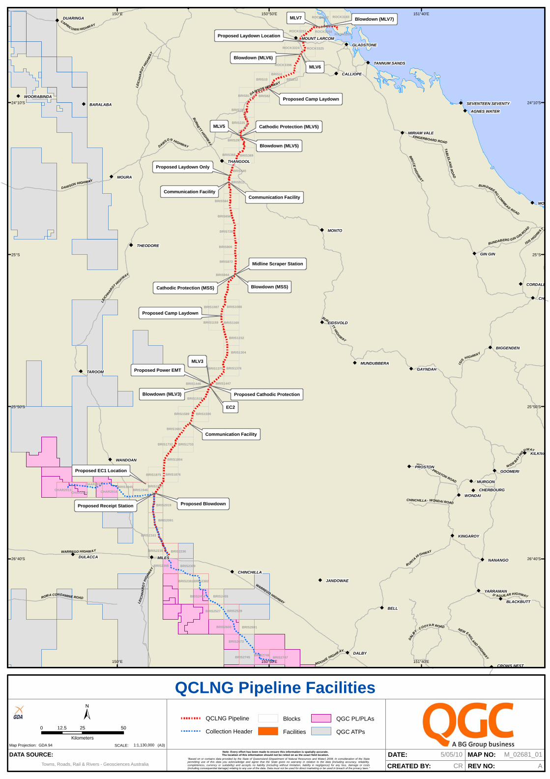
The pipeline route for the Gas Collection Header was detailed in the QCLNG EIS. The route commences at the Braemer State Forest. At this stage, construction in the State Forest cannot be avoided as this is related to the connection of Gas Field Component infrastructure. The route of the Gas Collection Header from Braemar State Forest to Wandoan is detailed in Figure 2. Figures 3, 4 and 5 indicate the land use along the Gas Collection Header route alignment.
Ö
Ö
Ö
Ö
Ö
Ö
Ö
Ö
Ö
Ö
Ö
Ö
Ö
Ö
Ö
Ö
Ö
Ö
Ö
Ö
Ö
Ö
Ö
Ö
ÖÖ
Ö
ÖÖ
Ö
Ö
Ö
Ö
Ö
Ö
Ö
Ö
Ö
Ö
Ö
Ö
ÖÖ
Ö
Ö
Ö
Ö
EC2
Proposed EC1 Location
Proposed Receipt Station
Proposed Camp Laydown
Proposed Camp Laydown
Proposed Laydown Only
Proposed Laydown Location
MLV5
MLV6
MLV7
Midline Scraper Station
Communication Facility
Communication Facility
MLV3
Proposed Power EMT
Proposed Cathodic Protection
Cathodic Protection (MSS)
Cathodic Protection (MLV5)
Blowdown (MSS)
Blowdown (MLV3)
Blowdown (MLV5)
Blowdown (MLV6)
Blowdown (MLV7)
Proposed Blowdown
Communication Facility
BRIS2308
BRIS1946
BRIS2382
BRIS2600
BRIS2454
BRIS2163
BRIS2455
BRIS2747BRIS2746
BRIS2673
BRIS2745
BRIS2528
BRIS2236
BRIS2091
BRIS2527
BRIS2235
BRIS1945
BRIS2381
BRIS2309
BRIS2601
BRIS2019
CHAR2016CHAR2014CHAR2013
CHAR2015
BRIS11
BRIS10
BRIS81
BRIS12
BRIS82
BRIS944
BRIS656
BRIS368
BRIS584
BRIS800
BRIS728
BRIS153
BRIS872
BRIS369
BRIS1160BRIS1159
BRIS1376
BRIS1732
BRIS1088
BRIS1589
BRIS1804
BRIS1876
BRIS1590
BRIS1518
BRIS1304
BRIS1232
BRIS1875
BRIS1947
BRIS1733
BRIS440
BRIS225
BRIS297
BRIS512
BRIS1375
BRIS1087
BRIS1661
ROCK3183
ROCK3325
ROCK3255ROCK3254ROCK3253
ROCK3324
ROCK3182
ROCK3396
BRIS1446 BRIS1447
BURNETT H
IGH
WAY
BR
UC
E H
IGH
WA
Y
LE
ICH
HA
R
DT HIG
H
WAY
B UNYA HIGHWAY
DAWSON HIGHWAY
ISIS
HIGHWAY
WARREGO HIGHWAY
CAPRICO RN HIGHWAY
D'AGUILAR HIGHWAYROMA CONDAMINE ROAD
NEW ENG
LA
ND HIGH
WAY
BUNDABERG
LOW
MEA
D ROAD
BUNDABERG GIN GIN R
OAD
W IDE BA
Y H
IG
HWAY
TA
BL
EL
AN
D R
OA
D
MOONIE HIGHW
AY
WONDAI - PROSTON ROAD
CHINCHILLA - WONDAI ROAD
FINGERBOARD ROAD
DA
LB
Y - COOYAR ROAD
BU
RN
ETT HIG
HW
AY
DAWSON HIGHWAY
LEIC
HH
AR
DT
HIG
HW
AY
DAWSON HIGHWAY
LE
ICH
HA
RD
T H
IGH
WA
Y
ISIS HIG
HWA
Y
WARREGO HIGHWAY
BELL
DALBY
MILES
MOURA
MONTO
TAROOM
WONDAI
MURGON
DULACCA
WANDOAN
GAYNDAH
NANANGO
GOOMERI
GIN GIN
YARRAMAN
KINGAROY
DUARINGA
JANDOWAE
BARALABA
CALLIOPE
THEODORE
GLADSTONE
BIGGENDEN
BLACKBUTT
CHERBOURG
MUNDUBBERA
CROWS NEST
CHINCHILLA
WOORABINDA
MIRIAM VALE
AGNES WATER
TANNUM SANDS
SEVENTEEN SEVENTY
MONTO
PROSTON
EIDSVOLD
CORDALB
CHI
KILKIVA
THANGOOLTHANGOOL
CALLIOPE
THEODORE
MOO
MOUNT LARCOM
151°40'E
151°40'E
150°50'E
150°50'E
150°E
150°E
24°10'S 24°10'S
25°S 25°S
25°50'S 25°50'S
26°40'S 26°40'S
QCLNG Pipeline Facilities
Map Projection: GDA 94
DATA SOURCE:
Towns, Roads, Rail & Rivers - Geosciences Australia"Based on or contains data provided by the State of Queensland (Department of Natural Resources and Water) 2008. In consideration of the Statepermitting use of this data you acknowledge and agree that the State gives no warranty in relation to the data (including accuracy, reliability,completeness, currency or suitability) and accepts no liability (including without limitation, liability in negligence) for any loss, damage or costs(including consequential damage) relating to any use of the data. Data must not be used for direct marketing or be used in breach of the privacy laws."
Note: Every effort has been made to ensure this information is spatially accurate.The location of this information should not be relied on as the exact field location.
SCALE: (A3)
DATE:
CREATED BY:
MAP NO:
REV NO:
M_02681_015/05/10
CR A
QCLNG Pipeline
Collection Header
Blocks
Facilities
QGC PL/PLAs
QGC ATPs
1:1,130,000
0 25 5012.5
Kilometers
±

CHINCHILLA
MILES
TARA
WANDOAN
CONDAMINE
WA
NT
QLD
SANSW
VIC
TAS
AREA OF DETAIL
ÜPROJECT:
CLIENT:
TITLE:
DATA SOURCE:
SCALE:
1:250,000 Topographic Raster copyright Geoscience AustraliaDCDB data copyright State of Queensland (2009)
21-April-2010
Collection Header CHPPL_1
Queensland Curtis LNG Project
GP0 Box 3107 - Brisbane QLD 4000p (07) 3024 9000 f (07) 3024 8999
w http://www.qgc.com.au e [email protected]
DATE:
Queensland Gas Company
DATE DRAWN APPROVED DRAWING NO. REV.
MA
P:
T:\C
lien
ts -
Pro
ject
s\Q
GC
\QG
C02
0-Q
CL
NG
\GIS
\Dat
a\W
ork
Req
ues
t\W
R_Q
GC
_011
53\W
R_Q
GC
_011
53_C
HP
PL
_1A
rcM
XD
:T:
\Clie
nts
- P
roje
cts\
QG
C\Q
GC
020-
QC
LN
G\G
IS\D
ata\
Wo
rk R
equ
est\
WR
_QG
C_0
1153
\WR
_QG
C_0
1153
_CH
PP
L_1
.mxd
1: 500,000 (A3) GDA94 Lat/Long
21.04.2010 EH JT A Gladstone
BRISBANE
Condamine
QUEENSLAND
NEW SOUTHWALES
WR_QGC_01153_CHPPL_1
Collection Header Pipeline
Export Pipeline
Cadastre
5 0 5 10 15 202.5
Kilometers
Unidel Group Pty Ltd does not guarantee the accuracy or completeness of the map and does not make any warranty about the data.Unidel Group Pty Ltd is not under any liability to the user for any loss or damage (including consequential loss or damage) which the user may suffer resulting from the use of this map.
Legend
PROPOSED PIPELINE ALIGNMENT
Export Pipeline & KPsCollection Header & KPs
REV NO DATE SUPPLIED BY
Rev GRev F
15-03-201015-03-2010
UnidelUnidel

430
419
CHINCHILLA
MILES
TARA
WANDOAN
CONDAMINE
WA
NT
QLD
SANSW
VIC
TAS
AREA OF DETAIL
ÜPROJECT:
CLIENT:
TITLE:
DATA SOURCE:
SCALE:
1:250,000 Topographic Raster copyright Geoscience AustraliaDCDB data copyright State of Queensland (2009)Mining Tenements Information copyright State of Queensland (Dept. of Mines & Energy)
21-April-2010
Collection Header Pipeline Surrounding Mining Tenements CHPPL 2b (Map 2 of 2)
Queensland Curtis LNG Project
GP0 Box 3107 - Brisbane QLD 4000p (07) 3024 9000 f (07) 3024 8999
w http://www.qgc.com.au e [email protected]
DATE:
Queensland Gas Company
DATE DRAWN APPROVED DRAWING NO. REV.
MA
P:
T:\C
lien
ts -
Pro
ject
s\Q
GC
\QG
C02
0-Q
CL
NG
\GIS
\Dat
a\W
ork
Req
ues
t\W
R_Q
GC
_011
53\W
R_Q
GC
_011
53_C
HP
PL
_2b
Arc
MX
D:
T:\C
lien
ts -
Pro
ject
s\Q
GC
\QG
C02
0-Q
CL
NG
\GIS
\Dat
a\W
ork
Req
ues
t\W
R_Q
GC
_011
53\W
R_Q
GC
_011
53_C
HP
PL
_2b
.mxd
1: 500,000 (A3) GDA94 Lat/Long
23.04.2010 EH JT A Gladstone
BRISBANE
Condamine
QUEENSLAND
NEW SOUTHWALES
WR_QGC_01153_CHPPL_2b
Export Pipeline
Collection Header Pipeline
Mining Development Lease
5 0 5 10 15 202.5
Kilometers
Unidel Group Pty Ltd does not guarantee the accuracy or completeness of the map and does not make any warranty about the data.Unidel Group Pty Ltd is not under any liability to the user for any loss or damage (including consequential loss or damage) which the user may suffer resulting from the use of this map.
Legend
PROPOSED PIPELINE ALIGNMENT
Export Pipeline & KPsCollection Header & KPs
REV NO DATE SUPPLIED BY
Rev GRev F
15-03-201015-03-2010
UnidelUnidel

253
273
278
226272
267
171
209
276
277
225
215
275
247
179229
747
676
648
702
692
651
692
692
810
810
702
810
810
867
1165
1367
787
813
1164
869
792
1015
1386
1041
1041
1118
1046
1132
1041
813
1041
1251
1148
1132
1041
1251
1132
1251
1251
1251
1251
1251
1251
CHINCHILLA
MILES
TARA
WANDOAN
CONDAMINE
WA
NT
QLD
SANSW
VIC
TAS
AREA OF DETAIL
ÜPROJECT:
CLIENT:
TITLE:
DATA SOURCE:
SCALE:
1:250,000 Topographic Raster copyright Geoscience AustraliaDCDB data copyright State of Queensland (2009)Petroleum Tenements Information copyright State of Queensland (Dept. of Mines & Energy)
21-April-2010
Collection Header Pipeline Surrounding Petroleum Tenements CHPPL 2a (Map 1 of 2)
Queensland Curtis LNG Project
GP0 Box 3107 - Brisbane QLD 4000p (07) 3024 9000 f (07) 3024 8999
w http://www.qgc.com.au e [email protected]
DATE:
Queensland Gas Company
DATE DRAWN APPROVED DRAWING NO. REV.
MA
P:
T:\C
lien
ts -
Pro
ject
s\Q
GC
\QG
C02
0-Q
CL
NG
\GIS
\Dat
a\W
ork
Req
ues
t\W
R_Q
GC
_011
53\W
R_Q
GC
_011
53_C
HP
PL
_2a
Arc
MX
D:
T:\C
lien
ts -
Pro
ject
s\Q
GC
\QG
C02
0-Q
CL
NG
\GIS
\Dat
a\W
ork
Req
ues
t\W
R_Q
GC
_011
53\W
R_Q
GC
_011
53_C
HP
PL
_2a.
mxd
1: 500,000 (A3) GDA94 Lat/Long
23.04.2010 EH JT A Gladstone
BRISBANE
Condamine
QUEENSLAND
NEW SOUTHWALES
WR_QGC_01153_CHPPL_2a
Export Pipeline
Collection Header Pipeline
Exploration Permit - Coal
Exporation Permit - Petroleum
Petroleum Lease
5 0 5 10 15 202.5
Kilometers
DATA NOT VERIFIED
Unidel Group Pty Ltd does not guarantee the accuracy or completeness of the map and does not make any warranty about the data.Unidel Group Pty Ltd is not under any liability to the user for any loss or damage (including consequential loss or damage) which the user may suffer resulting from the use of this map.
Legend
PROPOSED PIPELINE ALIGNMENT
Export Pipeline & KPs
Collection Header & KPs
REV NO DATE SUPPLIED BY
Rev G
Rev F
15-03-2010
15-03-2010
Unidel
Unidel

Environmental Management Plan Gas Collection Header Pipeline
Revision 3 – December 2011 QCLNG- BG00-ENV-PLN-000002
16 of 89
2.1 Description of Area
The following blocks and sub blocks listed below describe the areas for which this application is made.
Table 2.1: Block description
BLOCK BLOCK BLOCK BRIS1944 BRIS2454 BRIS2380 BRIS1945 BRIS2455 BRIS2452 BRIS1946 BRIS2527 BRIS2453 BRIS1947 BRIS2528 BRIS2526 BRIS2019 BRIS2600 BRIS2091 BRIS2601 BRIS2163 BRIS2673 BRIS2235 BRIS2745 BRIS2236 BRIS2746 BRIS2308 BRIS2747 BRIS2309 CHAR2013 BRIS2310 CHAR2014 BRIS2381 CHAR2015 BRIS2382 CHAR2016
Table 2.2: Lot and Plan Details for Gas Collection Header Pipeline
LOT & PLAN LOT & PLAN LOT & PLAN LOT & PLAN LOT & PLAN LOT & PLAN 3RP620202 1CP903915 1RP612108 13CTN301 3RW317 19PH524 63PM40 1RN1225 86DS636 12CTN301 1RW670 3SP104391 62PM40 15RN474 3MPH14076 25CTN406 7RW668 15FT111 70PM427 5RN516 1MPH14076 23CTN1233 16RW328 7NT243 67PM48 7RN1009 2DS725 7RP609065 13RW330 5NT364 66PM48 16RP883977 2SP108915 25CTN406 14RW329 42SP137907 111PM166 16RP883977 1SP108915 12SP199383 12RW330 42SP137907 156RN416 12RP912765 2SP157677 19CTN345 1RW333 2AU97 195RN415 DAP19580 4SP225924 4CTN406 3RW740 12AU174 70PM427 49PM187 3SP225924 31SP122298 1RW333 5NT196 68PM315 47PM164 2SP225924 1CL4032 3RW740 4NT195 BAP12253 42PM135 8SP200847 269CL4095 4WK198 07NT243 90PM74 43PM135 525CL40243 217CL4081 19PH524 42SP137907 87PM74 2RP616140 67CL40347 524CL40243 19PH524 2NT338 88PM73 194RN432 3RP801363 477CL40223 3SP104391 6NT354 24RN1599 193RN433 9SP200837 3SP217657 5WK207 302FTY1349 10RN52 23RN527 9SP200837 412CL40158 8WK171 6NT354 4RN903 43RN1261 137FTY1831 1RP616641 6RW337 17NT354 24RN1599 18RN1457 2MPH34582 1RP606302 3RW317 24AU146 4RN903 16RN517 137FTY1831 18CTN344 1RW330 23FT111 109PM165 4SP225924 45RP894241 13SP200915 15RW329 21FT111 18PM191 4RP620657 6CTN812615 1RP865974 1WK233 21FT111 19PM186 3SP101558 48CTN512 219CL40301 3WK225 17FT111 1PM191 201SP116496 49CTN512 217CL4081 1WK233 302FTY1349 49PM187 201SP116496 4RP860093 269CL4095 1RW341 AYNT233 40PM188 140SP122252 479CL40215 218CL4081 1RW341 4AU106 23RN527 3RP613702 525CL40243 16CTN344 1RW341 17FT111

Environmental Management Plan Gas Collection Header Pipeline
Revision 3 – December 2011 QCLNG- BG00-ENV-PLN-000002
17 of 89
The Gas Collection Header route selected has been assessed against a range of factors. These include:
• Topography and potential constructability of the large diameter pipeline;
• Potential environmental constraints;
• Commercial viability;
• Corridor length;
• Approvals and land access complexity; and
• Community impacts.
A final route was selected based on a risk assessment of these and other environmental and social factors including outcomes from public submissions and government consultation which occurred as part of the QCLNG EIS process. The outcomes of these assessments and community issues raised during the QCLNG EIS Process are detailed in Section 5 of this report.
3.0 DESCRIPTION OF PROJECT ACTIVITIES
The Gas Collection Header will link QGC’s production areas. This pipeline will be approximately 191.2 km in length and will generally extend from an area east of Tara to west of Wandoan.
3.1 Gas Collection Header Pipeline Specifications
The proposed pipeline (construction and operation) activities that may affect the environment include:
• Clearing pipeline construction corridors, referred to as a right-of-way (ROW), for installation of pipes;
• Excavation of pipe trenches;
• Pipe laying activities;
• Pipe laydown and storage areas;
• Restoration of the ROW;
• Borrow pits;
• Erecting and operating temporary accommodation camps and administration facilities;
• Communication facilities;
• Portable water supply or transport;
• Water management;
• Dangerous goods and fuel storage;
• Transport of plant, equipment and materials by road or rail and facilities to support the logistics of transport; and
• Maintenance and surveillance activities during operations.
3.2 Design Parameters
Metered, compressed, dry gas from each of the CPP’s will be collected and transported by collection laterals to the Gas Collection Header. Collection laterals will be located where required to connect a CPP to the collection header. The Gas Collection Header spans the length of the gas field and is approximately 191 km long. The Gas Collection Header connects to the Export Pipeline at the Receipt Station, which is located about 20 km SE of the town of Wandoan.

Environmental Management Plan Gas Collection Header Pipeline
Revision 3 – December 2011 QCLNG- BG00-ENV-PLN-000002
18 of 89
The Gas Collection Header and Export Pipeline are designed to free flow the peak feed gas demand of the LNG Plant. The pipeline may be modified to supply a third train of gas in future by the installation of mid-line compression.
Refer to Table 3.1 below for the operating and design temperatures, pressures and flows for each the Laterals, Gas Collection Header and Export Pipeline. The Gas Collection Header and Export Pipeline will be designed for full class 600 operation rated to 10,200 kPag as described by Australian Standard AS2885.
The Receipt Station contains metering facilities for custody transfer of gas from the Gas Fields to the Export Pipeline. A scraper station including coalescer/s will also be located at the Receipt Station. The sizing of filter coalescers will consider the expected TEG carryover and condensation from CPPs and the expected pigging frequency for the Gas Collection Header. A liquid storage vessel will be installed at the facilities to collect liquids should they occur.
The 42” Export Pipeline will transport gas to the LNG Facility at Gladstone and is approximately 333 km long. The Export Pipeline and Gas Collection Header provides buffer capacity to allow the gas production to be shutdown in an orderly manner in the event of an LNG Plant upset, and similarly, will provide line pack to allow the LNG Plant to be shut down in an orderly manner in the event of a loss of gas production from the field.
Table 3.1: Location Specific Operating and Design Gas Conditions for CSG to LNG1
Location Pressure, kPag Temperature, °C Flow, MMscfd
Min. Max. Operating Min. Max. Design Min. Max. Design
Well Head Separator
500 345 10 48 50 0.3 5 5
FCS Inlet 345 172 10 35 35 - 80 80
Inlet to Trunklines 1,8182 To be comfirmed2
207 55 55 - 80 80
CPP Inlet4 107 457 457
- 90 100
- 400 440
- 600 660
Inlet to Collection Header - 10,200 10,200 20 55 85 Refer to CPP sizes above
Delivery at LNG Plant6 5,500 10,200 5,500 10 35 85 4628 1,360 1,360
Notes: 1. These values are for performance assessment only and are not to be used for mechanical design of equipment. 2. The maximum pressure at the outlet of the FCS is based on the limit of 150# flanges, the design outlet pressure will be determined
based on trunkline hydraulic analysis 3. Inlet to Collection Header or a Collection lateral is at the battery limit isolation valve at the outlet of the CPP (prior to the pig
launcher) 4. Inlet to LNG Plant is at the LNG plant battery limit which is downstream of the inlet gas meter on the outlet of the filter coalescer. 5. These temperatures are indicative, actual range of operating temps to be determined by hydraulic analysis. 6. These are the min. and max. steady state operating conditions.
The design parameters (refer to Table 3.2 below) for the Gas Collection Header are described below. The depth of cover will (a) conform to AS2885 and (b) accommodate the requirements of the Department of Transport and Main Roads for road and rail crossings.

Environmental Management Plan Gas Collection Header Pipeline
Revision 3 – December 2011 QCLNG- BG00-ENV-PLN-000002
19 of 89
Table 3.2: Gas Collection Header Design Parameters
Pipeline Component Design Parameters
Gas Collection Header
Number of pipelines 1 * gas
Length (~ km) 191.2
Diameter (mm) 1067
Wall thickness (mm) minimum maximum
14.1 23.5
Material AP15L –X70
Coating External
Dual Layer Fusion-bonded epoxy
Internal Two-pack epoxy
Nominal Capacity 1,510 TJ/d
Maximum Allowable Operating Pressure 10.2MPa
Construction ROW (m) – average 40*
Depth of cover (min)1 Generally: 75cm
Deep cultivated areas: 1.2m
Road crossings22m
Rail crossings3 2m
Watercourse crossings 2m minimum
Corrosion Protection External coating and impressed current system
Non-destructive testing 100% non-destructive inspection of welded joints
Monitoring system Supervisory control and Data Acquisition (SCADA) connected to the QGC control centre
3.3 Cathodic Protection
A Cathodic Protection (CP) system will be installed on the pipeline to provide a secondary form of corrosion protection. The secondary system will consist of small power rectifiers and anode beds that will maintain the pipe at a negative potential to prevent corrosion should the coating become damaged. Anode beds are likely to be located at each end of the pipeline and at the scraper station.
1 Depth of HDD crossings will depend on geotechnical investigations, length and topography of the crossing, but will be greater than the
depths listed in this table. 2 Crossings of state-controlled roads corridors to be trenchless. 3 Crossings of railway corridors to be trenchless and in accordance with AS4799 Installation of underground utility services and pipelines
within railway boundaries.

Environmental Management Plan Gas Collection Header Pipeline
Revision 3 – December 2011 QCLNG- BG00-ENV-PLN-000002
20 of 89
Test points will be located at approximately 3 km to 5 km intervals along the pipeline to allow monitoring of the system. The CP system will be checked regularly to ensure that the protection voltages are within limits and will be monitored to ensure that any areas of corrosion activity are identified.
3.4 Corridor Widths and Access
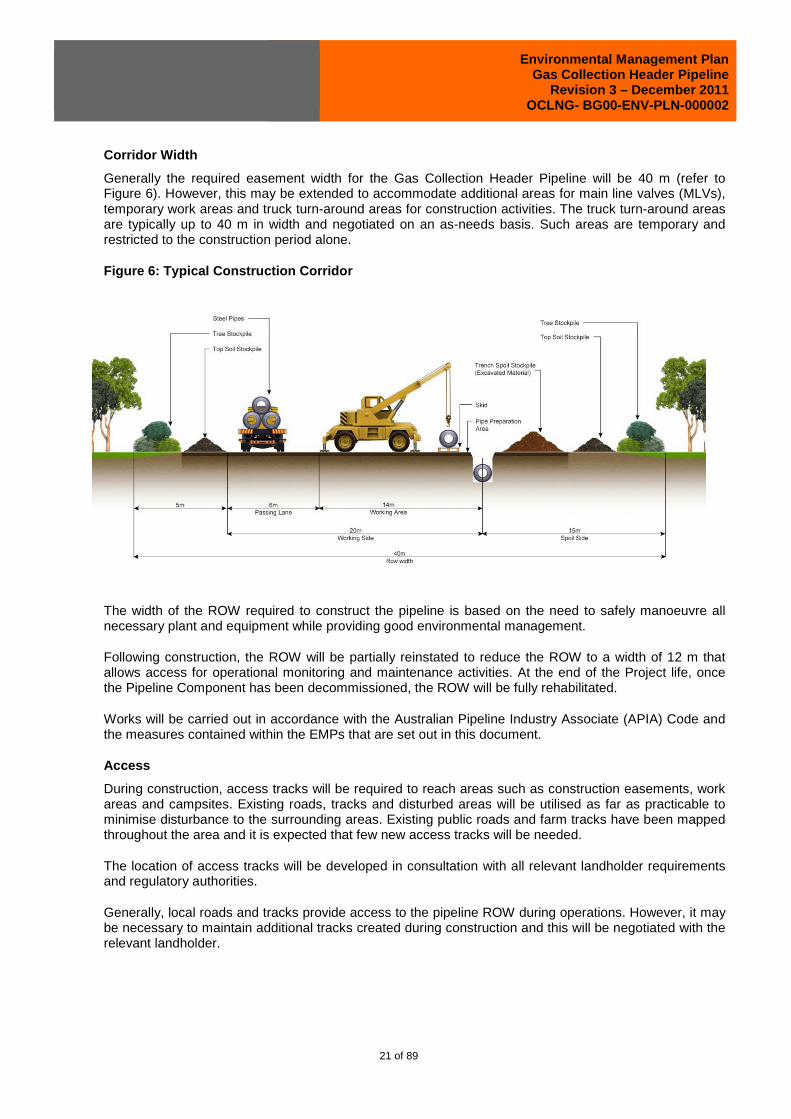
The requirement for a 40 m clearing width has been developed taking into account the volume of topsoil to be removed from the corridor, the volume of subsoil that will be removed from the trench, and safe working distances for the various pieces of equipment required for the construction of the pipeline. An engineering illustration for the ROW clearing is provided in Figure 6 below.
The base area for the soil stockpiles has been calculated using the following assumptions:
• mean topsoil depth along route of 15 cm (based on studies undertaken)
• mean subsoil depth of 1.85 m (typical trench depth of 2 m)
• predominance of duplex soils along the route
• typical stockpiled topsoil angle of repose of 30 degrees and bulking factor of 15 per cent (most topsoils are sands/sandy loam along route)
• typical stockpiled subsoil angle of repose of 45 degrees (usually 40 to 50 deg) and bulking factor of 30 per cent (most clays along route will be ‘cloddy’)
• stockpile heights of up to 2 m (or higher depending upon the site conditions) for short-term storage.
Environmental Management Plan Gas Collection Header Pipeline
Revision 3 – December 2011 QCLNG- BG00-ENV-PLN-000002
21 of 89
Corridor Width
Generally the required easement width for the Gas Collection Header Pipeline will be 40 m (refer to Figure 6). However, this may be extended to accommodate additional areas for main line valves (MLVs), temporary work areas and truck turn-around areas for construction activities. The truck turn-around areas are typically up to 40 m in width and negotiated on an as-needs basis. Such areas are temporary and restricted to the construction period alone.
Figure 6: Typical Construction Corridor
The width of the ROW required to construct the pipeline is based on the need to safely manoeuvre all necessary plant and equipment while providing good environmental management.
Following construction, the ROW will be partially reinstated to reduce the ROW to a width of 12 m that allows access for operational monitoring and maintenance activities. At the end of the Project life, once the Pipeline Component has been decommissioned, the ROW will be fully rehabilitated.
Works will be carried out in accordance with the Australian Pipeline Industry Associate (APIA) Code and the measures contained within the EMPs that are set out in this document.
Access
During construction, access tracks will be required to reach areas such as construction easements, work areas and campsites. Existing roads, tracks and disturbed areas will be utilised as far as practicable to minimise disturbance to the surrounding areas. Existing public roads and farm tracks have been mapped throughout the area and it is expected that few new access tracks will be needed.
The location of access tracks will be developed in consultation with all relevant landholder requirements and regulatory authorities.
Generally, local roads and tracks provide access to the pipeline ROW during operations. However, it may be necessary to maintain additional tracks created during construction and this will be negotiated with the relevant landholder.

Environmental Management Plan Gas Collection Header Pipeline
Revision 3 – December 2011 QCLNG- BG00-ENV-PLN-000002
22 of 89
Temporary and Permanent Aboveground Facilities
A range of temporary facilities will be required during pipeline construction. These include work areas for equipment, pipe delivery and storage. In addition, campsites for temporary accommodation of the construction workforce will be required. Occasionally, borrow pits to source additional fill material may be required. These additional work areas will be fully rehabilitated once the pipeline is operational.
Permanent aboveground facilities for the pipeline will include:
• mainline valves
• scraper stations
• communication towers
• cathodic protection facilities
• marker signs.
Construction activities are outlined in Table 3.3 below and include the potential for three spreads per pipeline.
Table 3.3 Construction Program Characteristics for Gas Collection Header Pipeline
Construction Element Details
Width of vegetation clearing 40m for the Gas Collection Header Pipeline Corridor
Depth of trench to provide the minimum depth of cover
Generally 2m
Deep Cultivated Areas 2,4m
Road Crossings 2.4/3.05m
Creeks and Rivers 2.4/3.2m
Trenchless techniques This can include boring, HDD or tunnelling. This technique is used, geotechnical constraints permitting, for rail line crossings, state controlled road crossings and watercourses and other environmentally sensitive areas (such as wetlands) where trenching techniques may cause unacceptable environmental disturbance.
Construction Workforce 500 for Gas Collection Header
Construction Spreads 2 construction spreads plus special crossing team
Standard construction hours 6 am – 6 pm seven days per/week
Construction duration (approximate) 18-24 months
Refuelling Mobile fuel truck and construction depot
Normal time between clear and grade and restoration
Up to four months
The crossing of any roads or rail lines will be carried out by a specialist crew, enabling the activity to be completed within a minimum timeframe. At no time will a road be permanently impassable and traffic management measures will be implemented.
All crossings of state-controlled roads and rail lines will be by trenchless techniques and there will be no interruption to rail traffic although some reduction in speed may be required. This will be negotiated with the relevant rail authority before the start of a specific crossing.

Environmental Management Plan Gas Collection Header Pipeline
Revision 3 – December 2011 QCLNG- BG00-ENV-PLN-000002
23 of 89
3.5 Design Criteria for Temporary or Permanent Acce ss Crossings
Temporary access crossings for machinery and transport across a waterway are dependent on the level of flow in the waterway. Dry waterway crossings are cleared in a similar manner to the remaining ROW, although all material removed is stockpiled back from the top of the bank and above the riparian zone. Vehicle access is then directly along the ROW.
If required, the area is compacted or felled timber may be laid across the traffic area to provide a more stable base. For waterways with a low volume of flow, a temporary culvert will be set up by installing pipes in line with the flow and providing compacted subsoil material over the pipe.
For waterways with heavy flows, an alternative crossing point will be located or timing for construction.
At locations where temporary crossings are created, all excess materials will be removed at the completion of construction and the area reinstated.
Permanent crossing points would normally be existing access tracks and the Project would not expect to create any permanent access crossings.
3.6 Watercourse Crossings
Further work has been done in relation to the potential construction method for crossing each of the various watercourses. A listing of the watercourses and their proposed method of crossing (minor crossing, major crossing or trenchless) is given in Appendix 1.
The Gas Collection Header watercourse crossings are classified as minor and major. In all, there are 82 minor open-cut crossings, 22 major open-cut crossings, including two proposed HDD crossings. The need to do HDD will be reviewed during detailed design.
A description of different crossing techniques is p rovided below.
Standard Open-Cut
This technique is suitable for the majority of watercourse crossings encountered along the various pipeline routes and for the crossing of unsealed local roads. It may also be applied to some low-traffic sealed roads where this will not create undue traffic interruptions.
Trenchless
The following trenchless techniques may be used where standard open-cut is not appropriate. These techniques are described below.
Horizontal Directional Drill (HDD)
This technique is used for trenchless crossings requiring long sections of pipe installation. It is suitable for road, rail and watercourse crossings but is predominantly used for watercourse crossings.
The feasibility of using HDD is limited by site conditions such as soil stability, slope, access, available workspace and nature of subsurface rock (gravel soils or cobble are not ideal for HDD). The length of the drill and the pipe diameter also influence the ability to use HDD as the risk of failure (unsuccessful construction) increases with pipe diameter and length of drill.
The installation of the pipeline by HDD involves drilling a hole at a shallow angle beneath the surface through which the pipe is threaded.

Environmental Management Plan Gas Collection Header Pipeline
Revision 3 – December 2011 QCLNG- BG00-ENV-PLN-000002
24 of 89
Drilling is conducted by a specially designed drill rig, operated by a specialist contractor. A variety of associated equipment and infrastructure is required. Note that the work area (equipment laydown) usually exceeds the standard ROW width, being typically about 50 m wide.
Although HDD substantially reduces the impacts in the immediate area of the crossing (such as to the bed and banks of watercourses), the technique can introduce additional environmental considerations. These include clearing of an area for the set-up of the equipment and pipe string, drill site sediment control, drill mud (water-based bentonite) management, potential for drill mud seepage through alluvial materials, and waste management. Access for vehicles and equipment around the watercourse is also required, resulting in the additional use, or creation of, access tracks.
HDD also has the potential for the drill bit to intersect a fracture within the underlying geology. Should this occur, bentonite mud may be released to the surface (such as into the watercourse). This event is referred to as a ‘frac out’ and may present a safety hazard in road and rail corridors and an environmental hazard in watercourses. Bentonite is a natural clay-like substance formed from the deposition of volcanic ash. When it is released into a watercourse through a ‘frac out’, it will cause increased turbidity until the material is fully dispersed.
If partial losses are experienced due to a frac out then a Loss Circulation Material (LCM) is added to the drilling fluid initially. The LCM would be a combination of bridging agents, fibres and flakes and swelling additives. If returns are not regained by treating with LCM, the drilling borehole assembly will have to be removed and a cementing application tried. In a dry watercourse, it is often preferable to leave the spilt bentonite in situ where it will dry out and break down into the surrounding area. Where a large spill occurs, the material can be excavated and disposed of by burial. Where a spill occurs within a rail or road corridor, material would be removed to ensure the safe operation of the infrastructure.
To address these issues, site-specific management procedures will be prepared before drilling as an outcome of the detailed design phase of this Project.
Boring
Boring is a low-impact technique involving drilling short distances from below ground within an enlarged trench area (bore pit) either side of the crossing location within the ROW This method may be used for road and rail crossings as well as for watercourses. For road and rail crossings, the bore pits are located outside the infrastructure corridor.
The feasibility of using a bore is limited by site conditions, including depth required, width of crossing, geology, landform, soil type and service/ infrastructure.
Tunnelling
Tunnelling is similar to boring but requires much larger bore pits, and micro-tunnelling equipment is used instead of a drill. This reduces the depth and distance required to achieve a HDD crossing with large-diameter pipe. The tunnel is lined with concrete sections through which the pipe is threaded. This method is not suitable for certain types of soil, such as gravels.
3.7 Timeframe And Staging
It is projected that construction of the Gas Collection Header will take between 18 and 24 months using two construction spreads, plus a special crossing team, and will require approximately 500 workers for the duration of the construction period.
The pipeline is projected to remain in operation for a period of approximately 20 years, before it is decommissioned.
Environmental Management Plan Gas Collection Header Pipeline
Revision 3 – December 2011 QCLNG- BG00-ENV-PLN-000002
25 of 89
3.8 Environmentally Relevant Activities
A number of Environmentally Relevant Activities (ERA’s) will be required for the construction and continued operation of the Gas Collection Header. Chapter 4 activities, as prescribed by the Environmental Protection Regulation 2008, if they are not environmentally relevant activities conducted under Chapter 5A, are likely to include:
• ERA 8: chemical storage;
• ERA 15: fuel burning;
• ERA 16: extractive and screening activities;
• ERA 17: abrasive blasting;
• ERA 18: boilermaking or engineering;
• ERA 56: regulated waste storage;
• ERA 57: regulated waste transport;
• ERA 60: regulated waste disposal and
• ERA 63: sewage treatment.
3.9 Notifiable Activities
Pursuant to Schedule 3 of the EP Act (defined below), the following notifiable activities may be undertaken during the construction and operation of the Gas Collection Header:
7. Chemical storage (other than petroleum products or oil under item 29) - storing more than 10t of chemicals (other than compressed or liquefied gases) that are dangerous goods under the dangerous goods code.
23. Metal treatment or coating - treating or coating metal including, for example, anodising, galvanising, pickling, electroplating, heat treatment using cyanide compounds and spray painting using more than 5L of paint per week (other than spray painting within a fully enclosed booth).
29. Petroleum product or oil storage - storing petroleum products or oil-
(a) in underground tanks with more than 200L capacity; or
(b) in above ground tanks with-
(i) for petroleum products or oil in class 3 in packaging groups 1 and 2 of the dangerous goods code-more than 2500L capacity; or
(ii) for petroleum products or oil in class 3 in packaging groups 3 of the dangerous goods code-more than 5000L capacity; or
(iii) for petroleum products that are combustible liquids in class C1 or C2 in Australian Standard AS 1940, 'The storage and handling of flammable and combustible liquids' published by Standards Australia-more than 25 000L capacity.
4.0 FINANCIAL ASSURANCE
COMMERCIAL IN CONFIDENCE The following financial assurance estimate is based on activities to be undertaken in the construction, operation and rehabilitation of the Gas Collection Header pipeline (see Table 4.1).

Environmental Management Plan Gas Collection Header Pipeline
Revision 3 – December 2011 QCLNG- BG00-ENV-PLN-000002
26 of 89
The key assumptions used in deriving the estimate are as follows:
1) Maximum of 40 m x 60 km graded and trenched at any one time = 240 ha
2) 30 km of pipe strung and bent
3) 30 km of pipe welded and joint coated
4) One HDD in progress
5) Allow 50 km of 8 m wide access tracks to rehabilitate = 40 ha
6) Two construction camps
7) Pipe removed from ROW and stockpiled nearby for collection by scrap metal merchant
8) Construction camps leased, lessor to remove but not clean up
9) Two workfronts included in calculation
10) Unit costs for these activities have been based on Financial Assurance estimates previously made by
QGC for DERM relating to existing QGC activities in the Surat Basin
11) Given ongoing refinement of camp layouts and design, the construction camp rehabilitation costs have
been calculated based on previous estimates of unit costs for existing QGC camps.

Environmental Management Plan Gas Collection Header Pipeline
Rev 3 - December 2011 QCLNG- BG00-ENV-PLN-000002
27 of 89
Table 4.1: DERM Financial Assurance Template for this Point-to-Point Pipeline Licence
Calculation of Financial Assurance for 192km of pip eline.
Pipeline Construction
Activity category / Disturbance type
Unit rehabilitation cost (GST included)
(from site-specific costs or Schedule in
Code)
Existing significant disturbance at
commencement of this Work
Program/Development Plan (e.g. number of
wells/pits/ponds)
Maximum additional significant
disturbance proposed during
term of Work Program/Development
Plan1
Rehabilitation of significant disturbance proposed during term
of Program/Plan
Maximum rehabilitation
cost (R) R = (B+C–D) x (A)
(A) (B) (C) (D)
Removal of strung and welded pipe, restoration of ROW as per attached work sheet, and in accordance with methodology report.
See calculation sheets
See assumptions on calculation sheets
113km 50km $3,665,200
Total rehabilitation liability for the term of the work program or development plan $3,665,200
Maintenance and monitoring costs (20% of rehab cost s to a maximum amount of $20, 000) $20,000
CPI (3% of total rehabilitation costs (compounded f or 1 year) $109,956
Financial assurance (Pay the difference between thi s amount and any financial assurance currently subm itted for this project) $3,795,156

Environmental Management Plan Gas Collection Header Pipeline
Rev 3 - December 2011 QCLNG- BG00-ENV-PLN-000002
28 of 89
5.0 STRUCTURE OF ENVIRONMENTAL MANAGEMENT
Section 5 describes the environmental factors and those mitigations measures that have been designed as part of the engineering works, consultation outcomes and as identified in the QCLNG EIS to protect Queensland’s environmental amenity and to prevent environmental harm in the construction and operation of the Gas Collection Header pipeline.
5.1 Environmental Factors
As the basis for preparing the EMPs, environmental factors have been identified for which there are environmental values. For each environmental factor, individual management plans have been proposed to manage impacts on the environmental values associated with the environmental factors. Environmental factors and associated EMPs are described in Table below.
This application relates only to the activities described in the Gas Collection Header PPL application. The following environmental factors are not impacted by these activities:
• Associated Water Storage
• Associated Water Management.
Table 5.1: Environmental Factors of the Gas Collection Header
Environmental Factor Management Plans Noise and Vibration Noise and Vibration Air Quality Air Quality and Dust Management
Greenhouse Gases Climate Change and Climate Extremes Climate Change and Climate Extremes Visual Amenity and Lighting Visual Amenity and Lighting Flora and Fauna Terrestrial Flora and Fauna
Weed and Pest Management (including Mosquitoes, Biting Midges and Fire Ants) Stock Access and Control
Water Surface Water Quality Groundwater
Land Soil Erosion and Sediment Control Soil Contamination Landscape and Character Maintenance Topography
Waste Waste Effluent Disposal
Traffic and Transport Traffic and Transport Health, Safety and Security Incidents and Complaints
Environmental Induction and Training Emergency Response for Environmental Incidents Fire Dangerous Goods
Rehabilitation and Decommissioning Progressive Rehabilitation Decommissioning
Social Community Heritage

Environmental Management Plan Gas Collection Header Pipeline
Rev 3 - December 2011 QCLNG- BG00-ENV-PLN-000002
29 of 89
5.2 Environmental Objectives And Performance Criter ia
For each environmental factor identified, an environmental objective and performance criteria has been determined. These are listed in Table 5. below for the QCLNG project.
Table 5.2: Environmental Objectives and Performance Criteria for Gas Collection Header
Element Objective Performance Criteria
Noise and vibration
To construct and operate in a manner that minimises the impact of noise and vibrations on surrounding residences and industry.
No exceedence of Project derived noise criteria at sensitive receptors. No noise-related complaints received from residents and landholders. Consultation with potentially affected sensitive receptors. Respond to all complaints.
Air quality and dust
To construct and operate in a manner that minimises impacts on ambient air quality.
No exceedence of Project derived air quality criteria at sensitive receptors. Consultation with potentially affected sensitive receptors. Respond to all complaints on air quality.
Climate extremes and climate change
Climate extremes and climate change do not adversely impact Project infrastructure.
Engineering design of Project infrastructure includes consideration of climate extremes and climate change.
Visual amenity To minimise impacts on visual amenity associated with the Gas Field.
Respond to all complaints regarding visual amenity and, where feasible, implement mitigation measures. Consultation with potentially affected sensitive receptors.
Lighting To reduce as much as practicable lighting impacts on sensitive receptors.
Respond to all complaints regarding lighting and, where feasible, implement mitigation measures. Consultation with potentially affected sensitive receptors.
Flora and Fauna To minimise impacts on the abundance and distribution of flora and fauna as a result of Project activities. Progressively rehabilitate all land significantly disturbed by construction to the pre-disturbed land use and suitability class.
Avoid, where practicable, endangered, vulnerable and near threatened (EVNT) flora species and the habitat of EVNT fauna. No unauthorised clearing of native vegetation. Permits and approvals in place for any unavoidable disturbance of EVNT flora and fauna species habitat. No introduction of declared pests as a result of Project activities. Minimise impacts to native vegetation and habitat fragmentation. Progressive rehabilitation occurs to restore areas consistent with pre-disturbance vegetation and surrounding ecology and land use. Provide suitable soil and landform conditions to encourage natural regeneration of native vegetation except within those areas required for ongoing maintenance and over the buried pipeline. Large trees will not be permitted within 5m either side of the pipeline. The re-establishment of native vegetation will include the shrubby understorey and ground cover, providing habitat for small ground dwelling fauna species and restoration of landscape connectivity. Develop and implement an offsets plan for the QCLNG Project incorporating the QCLNG GCH.
Weeds and pests To prevent the spread or
introduction of pest and weed species as a results of Project activities.
No increase in abundance or distribution of weed and pest species as a result of Project activities.

Environmental Management Plan Gas Collection Header Pipeline
Rev 3 - December 2011 QCLNG- BG00-ENV-PLN-000002
30 of 89
Element Objective Performance Criteria
Mosquito and biting midge
To undertake Project activities such that potential health impacts on Project personnel and nearby sensitive receptors arising from mosquitoes and biting midges are minimised.
Minimise potential mosquito and biting midge breeding sites resulting from Project activities.
Eastern Red Fire Ant
To prevent spread or introduction of Eastern Red Fire Ant as a result of Project activities.
No evidence of ERFA on Project sites.
Stock access and control
To minimise the impact on stock movements.
Where deemed necessary, stock access will be restricted from petroleum works sites. No stock injured or killed due to Gas Field Activities. No complaints from stock farmers
Surface water quality
To minimise the potential impacts associated with erosion and to prevent the release of contaminants that may adversely affect downstream surface water quality
No release of contaminants to surface waters outside the boundary of Project infrastructure. No failures of sediment and erosion control techniques leading to unacceptable sediment release.
Groundwater quality and availability
To protect the quality of the existing groundwater resources and not extract groundwater to the detriment of other groundwater users and biodiversity dependent on groundwater supplies.
Groundwater quality not impacted by activities. Develop trigger levels for the point at which changes to groundwater quality and levels may result in the implementation of groundwater management plans.
Associated Water storage
To minimise the environmental impacts related to the storage of Associated Water.
Ponds and water storage facilities will be managed in accordance with a Ponds Operational Plan Guide (POP Guide), Pond Operational Plans (POPs) and the Standard Pond Operating Procedures (SPOPs). Ponds will be designed and constructed to suitable engineering standards. No significant unplanned releases of Associated Water. No contamination of soils and water outside the footprint of storage ponds.
Associated Water management
To minimise the environmental impacts related to the transfer, treatment, release or beneficial use of Associated Water.
No significant unplanned releases of Associated Water. No contamination of soils and water outside the footprint of brine evaporation ponds or salt disposal facilities. Associated Water quality meets Project derived criteria specific to each beneficial use. Volume and timing of Associated Water utilised for any beneficial use will be in accordance with Project derived guidelines.
Soil erosion and sediment control
To minimise environmental impacts caused by soil loss and erosion.
Erosion and sediment control techniques implemented onsite where necessary. No failures of sediment and erosion control techniques leading to unacceptable sediment release.
Soil contamination No contamination of soils arising from Project activities. To manage any pre-existing contaminated soils such that extent of contamination is not exacerbated by Project activities. Minimise, where practicable, contamination of soils by Associated Water.
No release of contaminants, hazardous substance or dangerous goods to soil. Identify all pre-existing contaminated soils likely to be impacted by Project activities. Where pre-existing contaminated soils are identified, and disturbance by Project activities is unavoidable, develop and implement appropriate management strategies. No contamination of soils and water outside the footprint of water management infrastructure.

Environmental Management Plan Gas Collection Header Pipeline
Rev 3 - December 2011 QCLNG- BG00-ENV-PLN-000002
31 of 89
Element Objective Performance Criteria
Landscape and character maintenance
To minimise the impact on environmental and community values from the location of infrastructure.
Respond to all complaints regarding impacts on environmental and community values and, where feasible, implement mitigation measures. Consultation with potentially affected stakeholders. Evidence that decision criteria for location of infrastructure includes consideration of environmental and community values.
Topography maintenance
To minimise impacts to topography.
Minimise sediment and erosion release from areas where topography is altered. Consultation with stakeholders regarding topography following decommissioning. Where practicable, sites are returned to their original profile upon decommissioning.
Waste management
To minimise waste generation and maximise reuse and recycling of waste products. To dispose of waste in an appropriate manner.
No contamination of soil, air or water as a result of inappropriate waste management. Develop and implement a plan for waste minimisation and management. All waste disposal to be carried out by a licensed waste contractor. Waste management practices to not result in loss of health to personnel or sensitive receptors.
Effluent disposal To release treated effluent and manage sewage sludge without causing environmental harm.
Treated effluent meets quality requirements of design parameters. All sewage sludge is disposed at an appropriate sewerage disposal facility.
Traffic and Transport
To minimise as much as practicable potential impacts associated with traffic generated by the Project.
Minimal traffic-related complaints and incidents. To minimise impacts on road pavements, or where this is not practicable, to negotiate appropriate contributions or upgrades to road pavement impacts with relevant authorities.
Incidents and complaints
To have a process whereby all complaints can be lodged and responded to in an appropriate manner.
Record all complaints and responses in an incidents and complaints register. Respond appropriately to all incidents and complaints.
Environmental induction and ongoing training
To ensure that all Project personnel, including contractors, comply with the environmental requirements of all tasks.
All personnel undergo site inductions and, where necessary, additional training, that address environmental requirements of Project activities. Full compliance with induction and training procedures.
Emergency response for environmental incidents.
To ensure that Project personnel can respond effectively and efficiently in the event of an environmental incident to ensure no long-term adverse impacts on health, safety or the environment.
Any emergency response addressed in accordance with the QGC Emergency Response Plan. Nil government notices.
Fire management To prevent the initiation of bushfires as a result of Project Activities. To protect Project personnel and key Project infrastructure from bushfire impacts.
Develop and implement an Emergency Response Plan that includes fire management. No unplanned and uncontrolled fires caused by Project activities. Consultation with all relevant fire management authorities.
Dangerous goods and hazardous substances
To protect Project personnel, the public and the environment from harm due to the transport, storage or use of dangerous goods or hazardous substances.
No unplanned release of dangerous goods or hazardous substances. All transport, storage and handling of dangerous goods or hazardous substances is performed in accordance with applicable legislation, guidelines and standards.
Revegetation and rehabilitation
To restore, as far as reasonably practicable, land to its pre-
Prior to clearing, the native vegetation which is present will be surveyed as part of pre-clearance surveys to

Environmental Management Plan Gas Collection Header Pipeline
Rev 3 - December 2011 QCLNG- BG00-ENV-PLN-000002
32 of 89
Element Objective Performance Criteria existing condition prior to disturbance.
document such features as the regional ecosystem, species composition and condition.
Analogue sites will be established prior to rehabilitation commencing to establish benchmarks for rehabilitation for comparison against rehabilitation progress, and to verify compliance with performance objectives. Analogue sites will be assessed in accordance with the BioCondition assessment methodology (version 2.1) developed by the DERM.
Topsoil will be appropriately separated and stockpiled and reinstated within one month of completion of all construction activities in that area. For watercourses which drain an existing and named river, creek or tributary (not ephemeral) reinstatement will occur immediately post backfill to ensure impacts are minimised.
Re-profiling natural contours and drainage lines to their original profile to the greatest extent practicable taking into account landscape features and variation.
No weed species introduced.
Rehabilitation area stabilised with no significant erosion events until the vegetation is self-sustaining and for at least the first twelve months.
Respread felled native vegetation and timber over the ROW (but maintaining operational access to the buried pipe) to assist natural regeneration and provide habitat for ground-dwelling fauna.
Site specific rehabilitation plans will be prepared by the construction contractor based on the above criteria prior to rehabilitation commencing. These will address as a minimum areas of remnant vegetation and mapped MNES ecological communities and potential fauna habitats. These site specific rehabilitation plans will incorporate a range of aspects important to rehabilitation success such as soil type and appropriate vegetation and include details regarding site specific rehabilitation measures and performance objectives.
Decommissioning To decommission Project facilities
such that they do not present an ongoing environmental risk. To plan for decommissioning in consultation with relevant stakeholders.
Develop and implement, in consultation with stakeholders, a detailed decommissioning plan for all facilities prior to the end of their useful life.

Environmental Management Plan Gas Collection Header Pipeline
Rev 3 - December 2011 QCLNG- BG00-ENV-PLN-000002
33 of 89
6.0 ENVIRONMENTAL MANAGEMENT PLANS
The QCLNG Project draft EIS and supplementary EIS (sEIS) describe, in detail, the environmental values of the gas field, potential impacts on environmental values and measures to mitigate impacts.
EMPs have been prepared based on the findings outlined in Volume 4 of the QCLNG EIS. The management plans are consistent with BG Group’s Business Principles for the protection of environmental and social values across all the company’s activities, operations and projects.
6.1 Noise And Vibration
Environmental Values
The Gas Collection Header predominantly traverses rural areas, which in general is expected to have low background noise levels. The DERM Planning for Noise Control Guideline 2004 states that where background noise levels are less than 25 dB(A), a deemed background noise level of 25 dB(A) will apply. In accordance with these guidelines, QGC has adopted a deemed background level of 25 dB(A) for rural residential areas and a level of 30 dB(A) for urban residential areas.
Generally all noise impacts associated with the Gas Collection Header will occur during the construction of the pipeline. Construction activities will be limited to 12 hours per day. Where construction noise may impact on the acoustic environment of residential premises it is usually recommended that construction hours be limited to 7am to 6pm Monday to Friday, 7am to 1pm Saturday. Based on the recommended noise levels as described in the above mentioned DERM guidelines, QGC has adopted the following noise limits for pipeline construction activities:
• 45 dB(A) between 7am and 6pm from Monday to Friday
• 45 dB(A) between 7 am and 1 pm on Saturdays
• 30 db(A) at all other times.
Potential Impacts on Environmental Values
Potential noise impacts associated with the construction and the operation of the pipeline are projected to be minor and are expected to remain within the recommended noise limits as prescribed in the DERM guidelines. This is expected as the pipeline crosses predominantly rural areas and also as construction activities will be restricted to daylight hours wherever possible.
In the unlikely event that construction activities are required at night near sensitive receptors, these activities may be scheduled to occur when they generate the least disruption, or managed through negotiation of alternative arrangements with affected stakeholders.
Construction
All noise impacts associated with the construction of the pipeline will lead to temporary disturbances (if any) to sensitive receptors. Trenching and restoration works are expected to generate the highest noise levels. Other sources of noise will be associated with construction camps and traffic movements.
Vibration impacts which may occur as a result of the pipeline construction activities (excluding blasting) are projected to be minimal and therefore would remain predominantly within the 40 m ROW.
Construction works will occur during daylight hours, except in the following instances, where extended or continuous operation may be necessary:
• Boring or tunnelling for trenchless techniques – once boring or tunnelling has commenced the process is continuous to ensure the opening created does not collapse

Environmental Management Plan Gas Collection Header Pipeline
Rev 3 - December 2011 QCLNG- BG00-ENV-PLN-000002
34 of 89
• Water filling of the pipeline and pumping pressure are required for hydrotesting as testing cannot cease midway as the pipeline must be maintained at pressure during the testing procedures
• Works that do not pose an audible disturbance to any residences (i.e. in rural areas well away from residences)
• Transporting plant, equipment and pipe by oversized trucks outside of hours as required by authorities for safety reasons – this is a particular requirement for oversized truck movements, which may travel outside of daylight hours to minimise potential impacts on traffic movements
• In an emergency to avoid injury or loss of life, property and/or to prevent environmental harm where agreement is reached with local resident(s) to reduce construction duration and/or manage other traffic, amenity or disturbance issues
• Extenuating circumstances which are outside the Project’s control such as long periods of bad weather causing delays to the pipeline construction program.
Operation
The operating pipeline does not emit any discernible noise. On rare occasions it may be necessary to depressurise a section of the pipeline for safety or maintenance reasons. During this time – four to six hours – the noise emitted by the gas release will be in the vicinity of 130 dB(A) at the point of release, and the noise will be audible over a distance of 6 km to 10 km. Depressurisation would occur at main line valve and scraper station locations. Special procedures will be implemented to manage this event should it be necessary.
Noise and Vibration Management Plans
Table 6.1: Noise and Vibration Management Plan (Construction)
Noise and Vibration Management Plan (Construction) Operational Policy
To construct in a manner that minimises the impact of noise and vibrations on surrounding residences and industry.
Performance Criteria
• No exceedence of Project derived noise criteria at sensitive receptors. • Responded to all noise-related complaints received from residents and landholders and
implement mitigation measures. • Consultation with potentially affected sensitive receptors.
Implementation Strategy
• High noise events such as blasting will be scheduled during times of least impact to the local community.
• Community to be given adequate notice of any scheduled atypical noise events. • Any blasting to be carried out in accordance with relevant State legislation. • A plan will be prepared before blasting activities begin, giving consideration to potential air-
blast pressure and vibration and including mitigation measures. • Equipment will be fitted with noise-control devices. • Campsites, offices and stockpile sites to be located a sufficient distance from residences to
limit noise impacts. Monitoring and Auditing
• Landholder complaints relating to noise and vibration will be recorded and closed out by the Environmental Manager or delegate.
• Noise surveys at relevant local residences will be undertaken at the request of the administering authority.
• The method of measurement and reporting will be conducted in accordance with the DERM Noise Measurement Manual and/or AS 1055.
Reporting and Corrective Action
• The owner and construction contractor will maintain records of all monitoring and auditing activities and report results to the Environmental Manager at agreed intervals.
• Recommendations and corrective actions arising from audits and reviews will be implemented.

Environmental Management Plan Gas Collection Header Pipeline
Rev 3 - December 2011 QCLNG- BG00-ENV-PLN-000002
35 of 89
Noise and Vibration Management Plan (Construction) • Routine work reports will be recorded and reviewed by each supervisor or manager. • All incidents that deviate from normal operating conditions will be reported and action
initiated (including reporting to relevant agencies where this is warranted/required) by the owner and construction contractor to prevent a recurrence of the incident.
• Non-compliance and incident reports will be reviewed and closed out by senior management.
Table 6.2: Noise and Vibration Management Plan (Operation)
Noise and Vibration Management Plan (Operation) Management Policy
To operate in a manner that minimises the impact of noise and vibrations on surrounding residences and industry.
Performance Objectives
• No exceedence of Project derived noise criteria at sensitive receptors. • Responded to all noise-related complaints received from residents and landholders and
implement mitigation measures. • Consultation with potentially affected sensitive receptors.
Implementation Strategy
• Notify adjacent landholders of timing and duration prior to any maintenance activities creating excess noise along the ROW.
• Schedule, where possible, unavoidable loud noise activities (e.g. planned venting, pipeline blowdown) at times that will minimise nuisance to surrounding landholders.
• Notify landholders in advance of unavoidable loud noise activities where practicable. • Notify local residents, landholders and affected industries of any planned venting.
Monitoring • Landholder complaints relating to noise and vibration will be recorded and closed out by the Environmental Manager or delegate.
• Noise surveys at relevant local residences will be undertaken at the request of the administering authority.
• The method of measurement and reporting will be conducted in accordance with the DERM Noise Measurement Manual and/or AS 1055.
Reporting And Corrective Action
• Complaints relating to noise will be addressed promptly, with further investigations and reporting to the DERM if required.
• Routine work reports with maintenance records will be recorded and reviewed by each supervisor or manager.
• All works that deviate from normal operating conditions will be reported and action initiated (including reporting to relevant agencies where this is warranted/required) to prevent a recurrence of the incident.
• Non-compliance and incident reports will be reviewed and closed out by senior management.
• Regular reviews, recommendations and corrective actions shall be implemented.
6.2 Air Quality and Dust
Environmental Values
The Project environmental objective for air quality is to preserve ambient air quality to the extent that ecological health, public amenity or safety is maintained.
The air quality standards that have been considered during this assessment include:
• Environmental Protection (Air) Policy 2008 (EPP Air)
• National Environment Protection Measure for Ambient Air Quality (NEPM Air)
• BG Group corporate global air quality standards.

Environmental Management Plan Gas Collection Header Pipeline
Rev 3 - December 2011 QCLNG- BG00-ENV-PLN-000002
36 of 89
QGC will not exceed air quality objectives as set by the EPP Air, NEPM Air or the BG Group air quality standard. In general, the company standards are more stringent than the air quality objectives set by EPP Air and the NEPM Air.
Potential Impacts on Environmental Values
Construction
The construction earthworks and associated vehicle movements are likely to generate dust particularly during dry, windy weather conditions. No other major air contaminants are predicted to result as pipeline construction in high risk areas, such as rail lines, will be done using trenchless techniques.
Any impacts associated with dust generation are likely to be more adverse in areas located in proximity to sensitive receptors such as urban areas or residences. However, with the implementation of mitigation strategies, see Table 6.3 and 6.4, it is expected that dust concentrations within these sensitive areas will remain within acceptable limits.
Operation
Operation of the pipelines will generate air emissions from the following sources:
• Dust from ongoing management of the pipelines’ ROW
• Vented CSG from the pipelines.
• Dust generated during operations will be minimal in comparison to construction. Dust concentrations and fallout are expected to be within acceptable limits.
Hydrocarbon emissions from venting at various stages along the pipelines are likely to consist almost solely of unburnt CSG for which no air quality objectives have been published. Vented CSG is comprised of approximately 97% Methane. Although Methane is not a risk to air quality it is a known Greenhouse Gas. For further information about Greenhouse Gas emissions refer the section below Table 6.5.
Air Quality and Dust Management Plans
Table 6.3: Air Quality and Dust Management Plan (Construction)
Air Quality and Dust Management Plan (Construction) Operational Policy
To construct and operate in a manner that minimizes impacts on ambient air quality.
Performance Criteria
• No exceedence of Project derived air quality criteria at sensitive receptors. • Consultation with potentially affected sensitive receptors. • Respond to all complaints on air quality.
Implementation Strategy
• Vehicles and machinery to be fitted with appropriate exhaust systems and devices. Such devices will be maintained in good working order.
• Drive on unsealed surfaces, adjacent to residences, at speeds to minimise dust generation. • Haul roads to be well maintained. • Watering of the ROW, access tracks and topsoil stockpiles on an as-required basis to
minimise the potential for environmental nuisance due to dust. • Soil stockpiles to be kept as low as possible. • Watering frequency will be increased during periods of high risk (e.g. high winds). • The potential for generation of bulldust will be reduced through management and control
(e.g. watering, mulching cleared vegetation to provide a stable surface). • Community to be notified and consulted about scheduled construction activity likely to
generate dust. • Avoid smoke generation, with a strict no-burning policy. • Fire control procedures in welding operations.
Monitoring and Auditing
• Visual checks of dust emissions, particularly during windy/dry periods. • Water construction sites and access roads on an as-required basis (e.g. persistent dust

Environmental Management Plan Gas Collection Header Pipeline
Rev 3 - December 2011 QCLNG- BG00-ENV-PLN-000002
37 of 89
Air Quality and Dust Management Plan (Construction) emissions).
• Visual evidence of defective exhausts, and subsequent repair of relevant construction vehicle by contractor.
Reporting and Corrective Action
• The owner and construction contractor will maintain records of all monitoring and auditing activities and report results to the Environmental Manager at agreed intervals.
• Recommendations and corrective actions arising from audits and reviews will be implemented.
• Routine work reports will be recorded and reviewed by each supervisor or manager. • All incidents that deviate from normal operating conditions will be reported and action
initiated (including reporting to relevant agencies where this is warranted/required) by the owner and construction contractor to prevent a recurrence of the incident.
• Non-compliance and incident reports will be reviewed and closed out by senior management.
Table 6.4: Air Quality and Dust Management Plan (Operation)
Air Quality and Dust Management Plan (Operation) Management Policy
To operate the pipeline and associated facilities in a manner that maintains ambient air quality of the area.
Performance Objectives
• No exceedence of Project derived air quality criteria at sensitive receptors. • Consultation with potentially affected sensitive receptors. • Respond to all complaints on air quality.
Implementation strategy
• Minimise maintenance activities requiring purging of gas, and conduct under favourable weather conditions to facilitate rapid atmospheric dispersion.
• Undertake leakage detection surveys at flanges at regular intervals to detect fugitive gas emissions.
• Repair any detected leaks as a high priority. • Ensure vehicles and machinery exhaust systems are maintained in good working order. • Water sites and access roads for large excavation, construction or clearing works, as
required. • Venting, for commissioning or emergency situations, will be at appropriately located
valves. Monitoring • Gas will be metered prior to entering the pipeline using proven metering systems.
• Monitoring of compressor station air emissions through manual sample points within six months of commissioning and every two years of operation.
• Leak-detection surveys at flanges. • Monitoring of pipeline pressure. • Estimate and record volume of any gas vented.
Reporting and Corrective Action
• Landholder complaints will be recorded and action taken. • Non-Compliance and Incident Reporting will be undertaken by Operations Management to
ensure prompt rectification and, if required, initiation of changes to system.
Greenhouse Gases
The main Greenhouse Emissions Sources for the construction of the Gas Collection Header will be associated with truck movements for pipe deliveries/construction of campsites and personnel movements.
QGC is committed to minimising energy consumption and greenhouse gas emissions through continual improvement and technologies. It is committed to:
Environmental Management Plan Gas Collection Header Pipeline
Rev 3 - December 2011 QCLNG- BG00-ENV-PLN-000002
38 of 89
• Developing a Greenhouse Gas Management Plan
• Implementing an auditing and reporting program (including auditing and reporting requirements under the National Greenhouse and Energy Reporting System and the potential Carbon Pollution Reduction Scheme) through QGC’s annual internal performance reporting
• Project commitments relating to minimising energy consumption and greenhouse gas emissions through continual improvement and technological developments.
6.3 Climate Extremes And Climate Change
Environmental Values
Climate variability and climate change issues can potentially impact on the design life of the project as well as significantly alter the conditions in which the Gas Collection Header and associated infrastructure operates. Accordingly, infrastructure design is adapting to changes in rainfall patterns, changes in atmospheric temperature variation and increased intensity of storm events.
Climate Extremes and Climate Change Management Plan
Table 6.5: Climate Extremes and Climate Change Management Plan
Climate Extremes and Climate Change Management Plan Management Policy
Climate extremes and future climate change do not adversely impact Project infrastructure.
Performance Objectives
Engineering design of Project infrastructure includes consideration of climate extremes and climate change.
Implementation strategy
• Pipelines will be buried deep enough and adequately weighted down to prevent exposure during flood events or damage as a result of surface erosion from flooding.
• Pipeline routes will be subject to a visual inspection following significant rainfall or floods to ensure that the pipeline cover and any associated infrastructure is intact and has not been damaged.
• Revegetation strategies will include the selection of drought-tolerant grass species for stabilisation purposes.
• Strategies to mitigate impacts from extreme climate events and climate change include: o providing wet weather access to all construction sites o reduction, where appropriate, of construction activities during wet weather o sediment and erosion controls will be designed and implemented to cope with high
rainfall events o ensuring adequate dust, sediment and erosion management o monitoring short- and longer-term weather predictions o ensuring pipelines are buried deep enough to not be affected during flooding events o developing and implementing emergency response plans for extreme events including
fires and flooding o ensuring that all personnel are aware of and have rehearsed emergency response
measures in the event of flooding, fire and cyclones o Consideration of trenchless techniques, such as HDD, at major river crossings to
avoid risks associated with flood waters and to maintain stability of crossing area. Monitoring • Engineering designs of Project infrastructure include considerations of climate extremes
and climate change. • Audit of construction methods in accordance with engineering design that includes
consideration of climatic extremes and climate change. • Record all instances of failure of Project infrastructure caused by climatic extremes.
Reporting and Corrective Action
• All activities impacted by extreme weather will need to be re-assessed in light of any failures resulting in environmental impacts.
• All damage to pipeline infrastructure will be recorded and any actions to remediate sites will be recorded.
Environmental Management Plan Gas Collection Header Pipeline
Rev 3 - December 2011 QCLNG- BG00-ENV-PLN-000002
39 of 89
6.4 Visual Amenity And Lighting
Environmental Values
The majority of the area traversed by the Gas Collection Header has been highly modified by agricultural and grazing activities. The landscape within the view shed also has many elements of existing infrastructure such as roads, railways, transmission lines, communication towers, power lines, existing CSG infrastructure and power stations. Man modified landscapes are sources of lighting.
Undisturbed landscapes, which have a reduced capacity to absorb changes to the landscapes, include state forests and remnant vegetation.
The majority of the pipelines will be underground with only scraper stations, meter stations, MLVs and marker posts being the key aboveground elements. When the in-line compressor is required on the Gas Collection Header this will be the largest aboveground facility. In summary there are limited above-ground components associated with construction of the Gas Collection Header.
Potential Impacts on Environmental Values
The key visual characteristics of the pipelines fall into two categories:
• Temporary changes associated with construction
• Long-term changes associated with vegetation removal and the presence of above-ground infrastructure
Construction
Due to the presence of vehicles, trucks and earthmoving equipment, the ROW may be visible during the construction phase. This will be a temporary visual impact on the landscape. However, there will also be a visual impact associated with the removal of existing vegetation in some areas of the proposed ROW.
For pipeline corridors (i.e. the ROW), the visual impact associated with construction may also be more apparent from elevated viewing locations or across open areas with little or no intervening vegetation. This is because elevated viewing locations may be able to see longer sections of the ROW and the screening effect of vegetation is less apparent than when viewed from flatter or vegetated areas.
The location of the ROW will be more obvious where existing vegetation is removed prior to rehabilitation of the easement. The impact will diminish as rehabilitation works take effect. The ROW is likely to be more obvious in forested areas due to the loss of tall vegetation.
There will minimal visibility of the ROW from major roads which occur in proximity to the Gas Collection Header route. Where a pipeline runs parallel to the roads, once the route is rehabilitated the easement has the appearance of a widened road reserve and creates little visual impact.
Although there will be some views from highways, the overall impact is considered to be negligible due to the predominantly low landscape sensitivity and limited viewing opportunities afforded by topography and vegetation. Visibility from minor roads, which have far fewer users than the highways and main roads, is sometimes restricted by roadside vegetation. It is considered that the visual impact will be minor-to-negligible from these locations partly as the viewer numbers are low, but also because this rural landscape can absorb further change. Intersections with roads are normally less visible due to short interaction with the road easement.
There will be no visual impact on townships and minimal visibility from other settlements or residential dwellings in the area.

Environmental Management Plan Gas Collection Header Pipeline
Rev 3 - December 2011 QCLNG- BG00-ENV-PLN-000002
40 of 89
During construction, there may be limited instances of construction activities occurring at night and therefore requiring lighting. These instances will be limited in duration at any one location.
Operation
The only visual impacts during operation will be from scraper stations, meter stations, MLVs and marker posts. These latter items must be at distances such that they can be seen one from the other for safety requirements under Australian Standard 2885.
The only other visual amenity impacts that may arise during operations may be the lower canopy of the rehabilitating vegetation in the ROW. These impacts may be more evident where the pipeline traversed tall forests.
Visual Amenity and Lighting Management Plan
Table 6.6: Visual Amenity and Lighting Management Plan
Visual Amenity and Lighting Management Plan Policy To minimise impacts on visual amenity associated with the pipeline.
To reduce as much as practicable lighting impacts on sensitive receptors. Performance criteria
• Respond to all complaints regarding visual amenity and lighting and, where feasible, implement mitigation measures.
• Consultation with potentially affected sensitive receptors. Implementation strategy
• Route selection that ensures watercourse crossings and camps are located at an appropriate distance from residents.
• Consultation with landowners and neighbouring occupiers in relation to the location of camps.
• Lighting will be installed with reference to AS 4282-1997 Control of obtrusive effects of outdoor lighting.
Monitoring and auditing
• Visual amenity will be monitored from potentially affected viewsheds. • Landholder complaints relating to lighting will be recorded and closed out by the
Environmental Manager or delegate. Reporting and corrective action
• Complaints relating to visual amenity and lighting will be addressed promptly, with further investigations and reporting to the DERM if required.
• In response to DERM and or community concerns, appropriate remedies will be assessed in order to minimise potential impacts.
6.5 Flora And Fauna
Environmental Values
Pre-clearance surveys were undertaken in 2010 and 2011 along the entire Pipeline RoW and associated Camp and Pipe Laydown areas by suitably qualified ecologists approved by DSEWPC. As a result those EVNT flora species and threatened ecological communities (TECs) that do and do not occur within the RoW can be stated with confidence. The pre-clearance surveys also ground-truthed and verified the presence and extent of Endangered and Of Concern Regional Ecosystems (REs) within the RoW. The ground-truthed REs have been reflected in the mapping prepared for the QCLNG Pipeline Significant Species Management Plan (SSMP). DERM mapping has been used for Least Concern REs.
The Gas Collection Header Pipeline will require the clearing of one threatened ecological community (TEC) listed as Endangered under the Environment Protection and Biodiversity Conservation Act 1999 (EPBC Act), namely, Brigalow woodland/open forest community. This ecological community is represented by Regional Ecosystems (RE) 11.4.3 and 11.9.5 and occurs in small sections between kilometre posts (KP) 40

Environmental Management Plan Gas Collection Header Pipeline
Rev 3 - December 2011 QCLNG- BG00-ENV-PLN-000002
41 of 89
- 90. Based on pre-clearance surveys undertaken by Unidel ecologists within the 40m wide Gas Collection Header ROW between May and August 2010, a maximum area of 2.52ha of Brigalow TEC will be cleared.
Field assessment indicates that where the pipeline actually intersects a number of mapped REs the vegetation is mostly cleared and degraded and contains Buffel Grass.
Two Of Concern REs occur along the Gas Collection Header Pipeline (i.e. REs 11.3.2 and 11.3.4) totalling an area of 1.52ha. These communities occur as a mosaic within riparian vegetation at three locations transected by the proposed alignment (i.e. Wambo Creek at KP 61.2, the Condamine River at KP 66.8 and Columboola Creek at KP 88.4). Two TECs have been identified on the GCH being Brigalow and the Coolibah – Black Box Woodland. The Coolibah – Black Box Woodland TEC was recorded in an area adjacent to the Condamine River (between KP 68 and KP 69 which will be avoided as a result of horizontal directional drilling being used in this area. Up to 2.52 ha of Brigalow will be cleared.
There are 21 endangered EVNT flora species under the Queensland Nature Conservation Act 1992 (NC Act) known to occur in, or have ranges that overlap, with the Gas Collection Header Pipeline corridor. These species and their preferred habitats were targeted during pre-clearance surveys of the ROW by qualified ecologists.
Two EVNT flora species have been confirmed during pre-clearance surveys for the Gas Collection Header. These include Philotheca sporadica which is listed as Vulnerable under both the EPBC Act and the NC Act and has been recorded between KPs 23 and 24. The second species is Gonocarpus urceolatus which is listed as Vulnerable under the NC Act and has been recorded at numerous locations along the Gas Collection Header. QGC have obtained the necessary approvals from DERM and Department of Sustainability, Environment, Water, Population and Communities (DSEWPC) to clear these species within the ROW.
Database searches identified 17 EVNT fauna species (under the EPBC Act and/or the NC Act), 11 of which were considered to potentially occur in the area.
None of these EVNT fauna species were recorded in the vicinity of the Gas Collection Header Pipeline during field surveys.
The proposed alignment traverses cleared grazing country, vegetated land, several ephemeral watercourses and the Braemar State Forest. Fauna habitats on most rural lands and roadside verges are fragmented and substantially degraded. However, some areas, particularly riparian zones, have significant fauna habitat values with a relatively high percentage of hollow-bearing trees, moderate to dense levels of understorey vegetation and ground logs. In particular, the Gas Collection Header Pipeline traverses the Braemar State Forest between KPs 0.6-11. This area is considered to function as a fauna refuge area due to its large size, limited fragmentation and the rarity of weed infestations.
The aquatic environment occurring along the proposed alignment is limited to a number of ephemeral watercourses including Kogan Creek (KP 9.5), Wambo Creek (KPs 44 and 61.2), Columboola Creek (KP 88.4) and the Condamine River (KP 66.5). A small number of common aquatic plants including Cyperus spp. and Fimbristylis dichotoma were observed within and on the margins of these aquatic habitats.
Potential Impacts on Environmental Values
Construction
The principal impact on flora and fauna will be the clearing of native vegetation on easements for pipelines.
For each regional ecosystem conservation status, Table 6. presents the potential worst case vegetation clearing and the potential impacts of clearing within a local and bioregional perspective.
Table 6.7: Worst Case Vegetation Clearing Areas

Environmental Management Plan Gas Collection Header Pipeline
Rev 3 - December 2011 QCLNG- BG00-ENV-PLN-000002
42 of 89
RE/Ecological Community
Status
Clearing Extents
(ha)
Extent within 10 km (ha)
% of that within 10 km to be cleared
Extent in bioregion
% of that within
Bioregion to be cleared
EPBC listed1 2.52 467 0.06 76,888 <0.01
Endangered 0.12 467 0.06 76,888 <0.01
Of Concern 1.52 1,315 0.06 1,012,514 <0.01
Least Concern 174.19 34,864 0.50 2,499,139 <0.01
TOTAL 182.51 36,646 0.48 3,588,541 <0.01
1 EPBC-listed communities are overlapping (and not additional to) VM Act REs. Some Brigalow TECs areas do not constitute remnant status so are not included in the Endangered RE clearing extent.
Other potential detrimental impacts on biodiversity include:
• the movement of machinery and vehicles between areas, which has the potential to spread weeds including a number of environmental and declared noxious species, such as Buffel grass, parthenium weed and giant rat’s tail grass
• the introduction or proliferation of pest fauna species
• the activities of machinery and construction operations which may increase the likelihood of bushfires
• indirect impacts, being altered water, sediment and nutrient flows if watercourse disturbance is not effectively managed.
There are a number of ways that EVNT fauna could potentially be impacted by the proposed development including:
• removal of habitat such as mature vegetation, hollow-bearing trees and fallen logs may result in loss of nesting, shelter and foraging resources
• fragmentation of habitat due to pipelines and access road construction, may result in these features acting as movement barriers, particularly to fossorial4 species, thereby altering movement patterns. They may also limit access to dry-season fauna refuges associated with riverine environments
• predators may gain access. Dingoes and to a lesser extent foxes and cats are known to follow roads and tracks as they provide easy-access paths. This may open up new habitats and expose fauna to elevated predation risks
• the establishment of environmental weeds, particularly Buffel grass, has the potential to destroy natural fauna habitats through altered fire regimes and removal of fauna food resources
• noise and increased human activity, particularly during site development, may restrict species movements and limit access to food or other resources
• potential for trenchfall in which fauna species fall into and become trapped in the open pipeline trench during construction
• the potential for road kills along access tracks will elevate mortality risks for some species
• runoff may result in sedimentation and eutrophication of aquatic habitats.
4 Burrowing

Environmental Management Plan Gas Collection Header Pipeline
Rev 3 - December 2011 QCLNG- BG00-ENV-PLN-000002
43 of 89
Significant Species Management Plans (SSMPs) have been prepared to assist QGC and the Construction Contractor manage the environmental impacts upon Threatened Ecological Communities (TECs) and EVNT species listed under the EPBC Act and NC Act during construction, operation and decommissioning phases of the Project. The SSMPs have been prepared in accordance with the Project Development Approval Conditions set by DSEWPC, Queensland Coordinator-General and DERM. The QCLNG Pipeline SSMP (QCLNG-BG00-ENV-RPT-000002) outlines the general management procedures to be implemented, including what will occur if any new EVNT species are identified, and specific management and mitigation measures to be adopted for each species and community.
Mapping of the actual presence of TECs and EVNT flora species (verified through pre-clearance surveys undertaken by Unidel qualified ecologists approved by DSEWPC) is provided in the QCLNG Pipeline SSMP. Mapping of ‘potential habitat’ for MNES along the RoW, based on desktop analysis utilising the Unidel verified Endangered and Of Concern REs, and DERM Least Concern REs have been prepared. Potential habitat maps are provided within each individual SSMP and quantification of impacts for each MNES has been provided for the Gas Collection Header and Export Pipeline.
The following process will be implemented by the Construction Contractor and QGC to document and verify the disturbance to MNES prior to, and after, clearing:
• Environmental Constraints Maps (ECMs) will be prepared to cover all clearance areas. As well as incorporating information on a range of environmental aspects relevant to the construction team, the ECMs will incorporate information obtained from the pre-clearance surveys including the location of any identified MNES including known MNES breeding/habitat areas.
• Field Environment Officers will undertake a ‘pre-construction walkthrough’ to inspect the proposed disturbance areas at least five business days prior to clearing to identify any significant environmental features, including those areas mapped on the ECMs, and ensure those areas are appropriately flagged or fenced off where they can be avoided or lie adjacent to the clearing area; Any EVNT flora species which may be identified but have not been recorded in the pre-clearance surveys and captured on the ECMs will be recorded on a Flora Survey Form and managed in accordance with relevant regulatory requirements.
• During the ‘pre-construction walkthrough’ the Field Environment Officer will also refer to the SSMPs of the potential and confirmed MNES, to identify from the potential habitat mapping where the areas of higher likelihood for encountering MNES are located and to ensure any other additional mitigation measures are implemented
• Any confirmed MNES or identified potential or actual MNES habitat areas, as well as other significant environmental features which are not contained on the ECMs will be recorded in a pre construction Verification Checklist, which is used to ensure the construction team is apprised of the latest details within the clearance area including relevant environmental aspects. For any newly identified MNES to be impacted by the Pipeline which are not already identified in the Pipeline SSMP, a new SSMP will be prepared and provided to DSEWPC for approval prior to clearing commencing at that location.
• Following the Pre-construction walkthrough undertaken by the Environmental Field Officers, and within 24 hours prior to clearing, licensed Fauna Spotter Catchers will inspect the clearance areas for fauna species and breeding places and will be present at the time of clearing. All fauna including any MNES or NC Act species, which are identified, relocated or injured by the clearing process will be recorded on a Fauna Survey form and reported to the regulators in line with reporting procedures.
• Relevant details recorded on the pre-construction Verification Checklist will then be updated onto the ECMs, which as well as being a tool to identify environmental constraints to be observed during

Environmental Management Plan Gas Collection Header Pipeline
Rev 3 - December 2011 QCLNG- BG00-ENV-PLN-000002
44 of 89
the construction process, are intended as a means of documenting disturbance to EPBC and NC Act listed flora, communities and species habitats.
• The areas of confirmed TEC and NC Act Regional Ecosystems (RE) within the ROW which are contained within the ECM datasets will then be used to accurately calculate the disturbance areas for these listed flora, communities and species habitats. A summary register will be prepared to capture total clearing areas for each confirmed EVNT flora species, TEC and RE within the ROW and any confirmed actual MNES habitat areas and will also include any additional areas which may be cleared outside of the ROW.
• This process for the calculation of disturbance areas will be audited as part of routine project audits and in accordance with State and Federal regulatory requirements.
Due to limited availability of actual MNES habitat data, potential habitat areas may also be used in the calculation of offsets for MNES species. In order to provide more accurate potential habitat estimates than those provided by the desktop assessment, additional targeted ecological surveys may be undertaken to verify the presence of MNES or NC Act species within the areas identified as potential habitat through the desktop assessment. Further details on this process are provided in the QCLNG Pipeline SSMP.
Operation
During the operational phase of pipelines, easements will, as far as reasonably practicable, be rehabilitated to their pre-disturbance condition.
Flora and Fauna Protection Management Plans
Table 6.8: Flora and Fauna Protection Management Plan (Construction)
Flora and Fauna Protection Management Plan (Construct ion) Operational Policy
To minimise impacts on the abundance and distribution of flora and fauna as a result of Project activities. Progressively rehabilitate disturbed areas where practicable.
Performance Criteria
• Avoid, where practicable, areas of EVNT flora species and the habitat of EVNT fauna. • No unauthorized clearing of native vegetation. • Permits and approvals in place for any unavoidable disturbance of EVNT flora and fauna
species. • No introduction of declared pests as a result of Project activities. • Develop and implement an environmental offsets strategy. • Minimise impacts to native vegetation and on habitat fragmentation. • Progressive rehabilitation is consistent with the pre-clearance vegetation, surrounding areas
ecology and pre-disturbed land use.
• No remnant vegetation is cleared outside the ROW for temporary work areas (as per the Environmental Authority conditions).
Implementation Strategy
• Ensure DERM Forestry Products have been consulted in relation to extraction of millable timber.
• Potential habitat will be identified on site using potential habitat mapping prepared for each MNES species and contained within the individual SSMPs.
• As part of construction pre-start checks and completion of the Verification Checklist, Field Environment Officers will inspect the proposed disturbance areas at least five business days prior to clearing to identify any significant environmental features (including those areas mapped on Environmental Constraint Maps as TECs and ‘potential’ habitat for MNES species included in the SSMPs) and ensure those areas are appropriately flagged or fenced off where they can be avoided or lie adjacent to the clearing area.
• Ensure all clearing widths are clearly marked in the field prior to clearing works and at least 10km in front of any clear and grade activities. A Maximum ROW width of 40m is to be implemented.
• Where practicable, minimise the width of the ROW to 30m where adjacent to environmentally

Environmental Management Plan Gas Collection Header Pipeline
Rev 3 - December 2011 QCLNG- BG00-ENV-PLN-000002
45 of 89
Flora and Fauna Protection Management Plan (Construct ion) sensitive areas, including known habitat for EVNT species where identified on Environmental Constraints Maps and in riparian and micro habitat areas. Avoid areas of remnant brigalow and where not possible, minimise impact. Note: Pre-clearing surveys indicate that disturbance of approximately 2.52ha of brigalow is unavoidable within the GCH ROW. Additional walk through inspections will be undertaken within the ROW and for construction activity areas outside the ROW prior to clear and grade activities to identify these locations and minimise the extent of clearing wherever practicable.
• Avoid all Semi-evergreen Vine Thicket (SEVT) areas. Note: A Pipeline alignment has been adopted where there will be no impact to SEVT areas in accordance with Condition E 21 of Environmental Authority PEN100953310.
• If clearing in DERM-mapped wetland areas occurs, impact monitoring is to be implemented, which may include (as appropriate) surface water quality monitoring as well as targeted pre- and/or post-clearance ecological surveys. All impact monitoring shall be documented.
• Avoid the destruction of mature riparian trees unless presence compromises safe construction.
• No clearing of remnant vegetation, or areas of MNES, shall be undertaken for construction camps, additional work areas or vehicle access tracks. If any areas outside the ROW are identified for work areas pre-clearance surveys will be carried out to ensure they do not impact on environmentally sensitive areas and MNES.
• No disturbance of protected species without relevant permit. • Flag individual significant plant species (including habitat trees) within the easement that must
be avoided during construction. • Construction of physical barriers around significant vegetation areas in order to restrict
access and avoid disturbance. The type and extent of physical barriers will take account of the significant vegetation to be protected, level of protection required, as well as potential impacts on native fauna access and egress. Flagging tape (black and yellow) will be used to identify any Environmentally Sensitive Areas including vegetation to be retained on the ROW and any other laydown or storage areas. This coloured tape is in accordance with Pipeline Industry Code of Compliance. All such vegetation protection will be undertaken in accordance with the Australian Standard for Protection of Trees on a Construction Site where applicable.
• The Field Environment Officer will also ensure any other additional mitigation measures are implemented in accordance with the SSMP.
• Spotter catchers will inspect the areas proposed for clearing for fauna species and breeding places prior to clearing and details of identified, relocated or injured fauna will be recorded in in the Fauna Survey Form. Any, breeding places or confirmed habitat will be recorded in the pre-construction Verification Checklist for updating on the ECMs and will be managed in accordance with the SSMP procedures;
• Any EVNT flora species which may be identified but have not been recorded in the pre-clearance surveys and captured on the ECMs will be recorded on a Flora Survey Form and managed in accordance with relevant regulatory requirements.;
• Details of cleared TECs, EVNT flora species and REs will be updated into the ECMs and then into a summary register of vegetation disturbance areas.
• For any new confirmed MNES to be impacted by the Pipeline not already identified in the Pipeline SSMP, a new SSMP will be prepared and provided to DSEWPC for approval.
• Following clearing, the ECMs and the summary register of vegetation disturbance areas will be updated to enable accurate calculation of the areas of disturbance for monitoring of compliance with approval conditions and calculation of offset requirements,
• No burning of felled vegetation or deliberate lighting of fires. Rather, the felled vegetation should be stick raked into piles and left for redistribution to provide animal habitat and to assist in revegetation and erosion control. This will further encourage regrowth within these communities, as well as minimise weed infestations. Vegetation shall not be pushed into gullies, waterways or other drainage lines or into Brigalow TEC or RE areas or other MNES areas.
• Whilst construction will be year round, where construction occurs outside of the driest months, additional trench surveillance will be undertaken, when reptiles and amphibians are least active and conditions are most favourable for minimising mortality in the trench.
• Qualified spotter catchers will be used to survey, record and relocate wildlife immediately prior to and during clearing and trenching activities.
• Trenching to occur progressively to minimise the period of time trenches are open, as well as

Environmental Management Plan Gas Collection Header Pipeline
Rev 3 - December 2011 QCLNG- BG00-ENV-PLN-000002
46 of 89
Flora and Fauna Protection Management Plan (Construct ion) their length. Any one continual length of open trench will not exceed 15km and the maximum cumulative amount of open trench from different work fronts will not exceed more than 40km of open trench at any one time. Open trenching works will last for a duration of approximately 6 weeks at any one location due to the nature of associated hydro-testing requirements for the pipe.
• Install fauna escape ramps or ladders in all open-trench areas along pipelines. • Maintain contact details for qualified veterinarian staff who can assess, treat or euthanise (as
necessary) any large native vertebrates. • Ensure no permanent barrier to fish movement at any stage of the Project. Note: Review of
the design drawings indicates that there will be no permanent structure above creek bed level. Any temporary creek crossing works will be undertaken in accordance with the following DERM and DEEDI documents to prevent impacts on any State and Federally listed species:
• DEEDI Code – Temporary waterway barrier works; • DEEDI Code – Self-assessable development minor waterway barrier works (Sept
2010); and • DERM Guideline – activities in a watercourse, lake or spring associated with
mining operations (v2). • Strict no-weapons and no-pets policy for workforce. • All vehicles to remain on designated access roads and tracks and within defined pipeline
construction area and associated work/camp sites. • Vehicle movements are not permitted at night without express authorisation from the site
manager. Vehicle operation hours will be 6 am - 6 pm (maximum 12 hours per day), 7 days a week. This will be monitored through in-vehicle monitoring systems (IVMS) on all vehicles. If night driving is required along the ROW it will be at 20km/hr for safety reasons and to minimise the likelihood of hitting fauna species.
• During standard operating hours (6am-6pm) vehicles will travel along the ROW at appropriate speeds that minimise environmental risks. Speed limits will be defined for, and signposted on the verge of, specific sections of unsealed access tracks and along the ROW. Speed limits will be dependent on the nature of the particular track section and relevant Project HSSE requirements. The standard speed limit is 40km/hr and in environmentally sensitive areas (including those areas mapped as potential habitat in the SSMP) it will be reduced to 20km/hr to minimise the likelihood of hitting fauna species.
• Specific mitigation measures will be implemented where required by species specific SSMPs. • Existing roads and tracks will be utilised for access where practicable. • All land disturbed by the pipeline will be rehabilitated to its pre-disturbance land use and
suitability class. The re-establishment of native vegetation will primarily be through managing natural regeneration and will include shrubby understorey and ground cover to provide habitat for ground dwelling fauna and restoration of landscape connectivity. Further details pertaining to the method of rehabilitation, monitoring and performance outcomes are included in the Pipeline SSMP and future site specific rehabilitation plans are to be prepared by the Construction Contractor in consultation with landowners and QGC prior to rehabilitation commencing.
• Spreading of cleared vegetation, logs, hollows and dead timber across the disturbed areas within woodland fauna habitats will be carried out immediately after disturbance to facilitate small ground-fauna movement.
• Bare vehicle tracks will be minimised following the rehabilitation of the corridor post-construction.
• Environmental Offset Initiatives will be implemented in accordance with the QCLNG Pipeline Offsets Plan.
• Where construction is required in the vicinity of watercourses mitigation measures as detailed in the QCLNG Pipeline Aquatic Values Management Plan (AVMP) (QCLNG-BG00-ENV-RPT-000009) will be implemented. The overall intent of the AVMP is to provide an assessment of aquatic values at watercourse crossings along the Pipeline ROW and to outline the mitigation measures which shall be implemented to minimise impacts to these aquatic values, in particular MNES.
Monitoring and Auditing
• During construction, the entire length of the ROW and associated work areas will be regularly inspected to assess the effectiveness of protection measures with particular attention to flora

Environmental Management Plan Gas Collection Header Pipeline
Rev 3 - December 2011 QCLNG- BG00-ENV-PLN-000002
47 of 89
Flora and Fauna Protection Management Plan (Construct ion) and fauna protection and management.
• Specific measures from SSMPs applicable to confirmed species or TECs will be implemented.
• Throughout construction, the entire length of the open trench will be inspected twice daily (morning and evening) by approved spotter catchers.
• The construction contractor’s spotter-catchers will use a Fauna Survey Form to record all fauna survey, removal and relocation activities. This fauna survey sheet shall include the following information: the date, location, weather conditions, name of the spotter catcher, scientific and common species names, the number of species and the actions - such as relocation, treatment, death. This information shall be retained as part of the construction team environmental records and provided to DERM on a three monthly basis as a Return of Operations form in accordance with Damage Mitigation Permit requirements. Any injuries or deaths to vertebrates will also be reported to DERM within 24 hours.
• The ECMs and a summary register of vegetation disturbance areas will be updated after clearing, to document the regional ecosystems, TECs and listed flora species impacted and enable calculation of disturbance areas. This summary register will specify the nature of the listed vegetation or listed species habitat type, the areas cleared and the location..
• The Fauna Survey Form, and the process and documentation used for capture and calculation of vegetation disturbance areas will be audited as part of routine project audits and in accordance with State and Federal regulatory requirements.
• The process used to calculate disturbance to MNES habitat for offsetting purposes is detailed in the Pipeline SSMP and will also be included in the routine project audits.
• Environmental Offset initiatives will be audited against objectives established in the QCLNG Pipeline Offsets Plan.
• Conditions of the Environmental Authority (EA) require that a third party audit be conducted for compliance with EA conditions on an annual basis.
Reporting and Corrective Action
• The owner and construction contractor will maintain records of all monitoring and auditing activities and report results to the Environmental Manager at agreed intervals.
• All clearing and impacts will be recorded by the construction contractor and maintained in an appropriate registers. Therefore all pipeline approved disturbed limits will be monitored and complied with. Any additional impacts that may be required will be reported to the relevant government regulators and approved.
• Information gathered on the number and varieties of fauna removed from trenches will be presented to the relevant authorities in the State (e.g. Queensland Museum).
• Offset Audits will be reported annually. Actions to address failed objectives will be developed, implemented and reviewed as part of the annual audit process.
• Recommendations and corrective actions arising from audits and reviews will be implemented.
• Routine work reports will be recorded and reviewed by each supervisor or manager • All incidents that deviate from normal operating conditions will be reported to the
Environmental Manager and corrective action initiated by the owner and construction contractor to prevent a recurrence of the incident
• Reporting to the relevant agencies where this is warranted/required will be carried out by the Environmental Manager.
• Non-compliance and incident reports will be reviewed and closed out by the owner.
Table 6.9: Flora and Fauna Protection Management Plan (Operation)
Flora and Fauna Protection Management Plan (Operation ) Management Policy
To minimise impacts on the abundance and distribution of flora and fauna as a result of Project activities. Progressively rehabilitate disturbed areas where practicable.
Performance Objectives
• Avoid, where practicable, clearing of EVNT flora species and the habitat of EVNT fauna. • No unauthorised clearing of native vegetation. • Permits and approvals in place for any unavoidable disturbance of EVNT flora and fauna

Environmental Management Plan Gas Collection Header Pipeline
Rev 3 - December 2011 QCLNG- BG00-ENV-PLN-000002
48 of 89
Flora and Fauna Protection Management Plan (Operation ) species.
• No introduction of declared pests as a result of Project activities. • Minimise impacts to native vegetation and on habitat fragmentation. • Progressive rehabilitation is consistent with the surrounding area and land use post
restoration. Implementation Strategy
• Inspect condition of revegetation on ROW during regular surveys and patrols. • Implement and maintain weed management strategy (refer to Section 6.6). • Restrict clearing of vegetation to large vegetation regrowth occurring within the three metres
of the pipeline centreline. • Stockpile topsoil and subsoil separately where excavation is to be undertaken, to maintain
grass seed stock and re-spread once the pipeline trench has been filled in. Stockpiles will be managed to prevent erosion and placed away from waterways.
• Soil profiles will be re-established consistent with the pre-disturbance profiles and land form to enhance the success of natural regeneration.
• Maintain records of properties where pest-control infrastructure is in place or is installed. • Ensure all vermin or dingo fencing is re-established and gates are closed. • Where soil is exposed, re-establish with appropriate grass species in accordance with the
surrounding landscape wherever possible to minimise fragmentation and prevent impacts on natural ecosystem functioning and fauna movement. Rehabilitation to be in accordance with site specific rehabilitation plans developed for the appropriate vegetation community.
• All vehicles to remain on designated access roads and tracks and within the defined ROW and associated work/camp sites.
• Vehicle movements are not permitted at night without express authorisation from the site manager. Vehicle operation hours will be 6 am - 6 pm (maximum 12 hours per day), 7 days a week. This will be monitored through in-vehicle monitoring systems (IVMS) on all vehicles. If night driving is required along the ROW it will be at 20km/hr for safety reasons and to minimise the likelihood of collision with fauna species.
• During standard operating hours (6am-6pm) vehicles will travel along the ROW at appropriate speeds that minimise environmental risks. Speed limits will be defined for, and signposted on the verge of, specific sections of unsealed access tracks and along the ROW. Speed limits will be dependent on the nature of the particular track section and relevant Project HSSE requirements. The standard speed limit is 40km/hr and in environmentally sensitive areas (including those areas mapped as potential habitat in the SSMP) it will be reduced to 20km/hr to minimise the likelihood of hitting fauna species.
• Specific mitigation measures will be implemented where required by species specific SSMPs.
Monitoring • Ongoing monitoring (pipeline and above-ground facilities) will be undertaken to assess the success and integrity of revegetation and to ensure appropriate follow-up measures are implemented.
• Monitoring will occur weekly until the rehabilitated areas are considered stable, and then at least monthly for the first 12 months post construction. Details of the monitoring method to be used will be detailed in the site specific rehabilitation plans to be developed prior to commencement of rehabilitation works.
• Monitoring will then be undertaken annually until the rehabilitation has met the set performance objectives using the BioCondition assessment methodology.
• Regular audits and reviews will be undertaken and recommendations and corrective actions shall be implemented.
• Spotter catchers will be present during clearing and monitor clearing activities to ensure direct impacts to fauna are avoided and minimised.
Reporting and Corrective Action
• Non-Compliance and Incident Reporting (refer to Section 6.22) will be actioned by Operations Management to ensure prompt rectification and, where required, initiated changes to systems.
• Landholder complaints will be recorded and actioned.
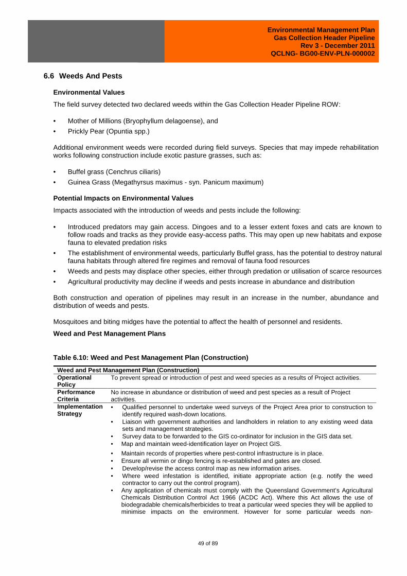
Environmental Management Plan Gas Collection Header Pipeline
Rev 3 - December 2011 QCLNG- BG00-ENV-PLN-000002
49 of 89
6.6 Weeds And Pests
Environmental Values
The field survey detected two declared weeds within the Gas Collection Header Pipeline ROW:
• Mother of Millions (Bryophyllum delagoense), and
• Prickly Pear (Opuntia spp.)
Additional environment weeds were recorded during field surveys. Species that may impede rehabilitation works following construction include exotic pasture grasses, such as:
• Buffel grass (Cenchrus ciliaris)
• Guinea Grass (Megathyrsus maximus - syn. Panicum maximum)
Potential Impacts on Environmental Values
Impacts associated with the introduction of weeds and pests include the following:
• Introduced predators may gain access. Dingoes and to a lesser extent foxes and cats are known to follow roads and tracks as they provide easy-access paths. This may open up new habitats and expose fauna to elevated predation risks
• The establishment of environmental weeds, particularly Buffel grass, has the potential to destroy natural fauna habitats through altered fire regimes and removal of fauna food resources
• Weeds and pests may displace other species, either through predation or utilisation of scarce resources
• Agricultural productivity may decline if weeds and pests increase in abundance and distribution
Both construction and operation of pipelines may result in an increase in the number, abundance and distribution of weeds and pests.
Mosquitoes and biting midges have the potential to affect the health of personnel and residents.
Weed and Pest Management Plans
Table 6.10: Weed and Pest Management Plan (Construction)
Weed and Pest Management Plan (Construction) Operational Policy
To prevent spread or introduction of pest and weed species as a results of Project activities.
Performance Criteria
No increase in abundance or distribution of weed and pest species as a result of Project activities.
Implementation Strategy
• Qualified personnel to undertake weed surveys of the Project Area prior to construction to identify required wash-down locations.
• Liaison with government authorities and landholders in relation to any existing weed data sets and management strategies.
• Survey data to be forwarded to the GIS co-ordinator for inclusion in the GIS data set. • Map and maintain weed-identification layer on Project GIS. • Maintain records of properties where pest-control infrastructure is in place. • Ensure all vermin or dingo fencing is re-established and gates are closed. • Develop/revise the access control map as new information arises. • Where weed infestation is identified, initiate appropriate action (e.g. notify the weed
contractor to carry out the control program). • Any application of chemicals must comply with the Queensland Government’s Agricultural
Chemicals Distribution Control Act 1966 (ACDC Act). Where this Act allows the use of biodegradable chemicals/herbicides to treat a particular weed species they will be applied to minimise impacts on the environment. However for some particular weeds non-

Environmental Management Plan Gas Collection Header Pipeline
Rev 3 - December 2011 QCLNG- BG00-ENV-PLN-000002
50 of 89
Weed and Pest Management Plan (Construction) biodegradable chemicals/herbicides may be the only option. Any person applying chemicals will hold the relevant licences and use them in accordance with relevant regulations and project HSSE requirements. Any relevant Pest Fact Sheets produced by DEEDI will be consulted.
• Vehicles, plant and equipment must travel on approved access routes only (Approved Access Mapping).
• Plan construction activities to minimise the spread of weeds. • Limit vehicle movements on vegetated areas that may contain weed material. • Vehicles travelling from weed-affected areas must wash-down prior to leaving these areas
or prior to re-entering the road network. • All vehicles, plant and equipment (including hand tools such as shovels) will be inspected
by nominated personnel before being certified clean for entry to the Project Area. • All vehicles, plant and equipment will be kept visually clean (as practicable) and kept free of
grass and other materials where possible. • Equipment and vehicles will be cleaned in designated wash-down sites before leaving
weed-infested areas or entering weed-free areas. • Personal clothing, including boots, will be cleaned of mud and weed seeds nightly as well
as whenever leaving weed-infested areas. Trouser pockets and cuffs are to be turned out to remove any seeds.
• Vehicles, plant and equipment that fail inspection must be washed down and re-inspected. • A log, to be completed for all wash-down activities, is to be maintained at the construction
site office and made available to the Environmental Manager, auditors or regulators on request.
• Only identified wash-down facilities will be used (refer GIS maps). • Wash-downs to be managed so as to not leave a weed seedbank. • Ensure potential mosquito-breeding sites, including equipment and materials that pool
water, are avoided or drained regularly. Any such equipment or debris no longer required for construction will be disposed of as soon as possible.
• Campsite and Office Supervisors and Construction Superintendents will be trained to recognise mosquito-breeding activity and the treatment of breeding sites.
• Periodic inspection of any ponded water to ensure no mosquito breeding occurring. • Removal of any mosquito breeding site from Project related source.
Monitoring and Auditing
• During construction, the entire length of the ROW and associated work areas will be inspected monthly to assess the effectiveness of weed protection measures.
• Regular audits will be undertaken, and recommendations and corrective actions will be implemented.
Reporting and Corrective Action
• Non-Compliance and Incident Reporting will be reported to, and regulated by, senior management to ensure prompt rectification and change management as required.
• Landholder complaints will be recorded and appropriately acted upon by the Environmental Manager
• A survey of weed-prone areas to be conducted after early wet-season rainfall events and thereafter monthly during the first wet season, if access allows.
Table 6.11: Weed and Pest Management Plan (Operation)
Weed and Pest Management Plan (Operation) Operational Policy To prevent spread or introduction of pest and weed species as a results of Project
activities. Performance Criteria No increase in abundance or distribution of weed and pest species as a result of Project
activities. Implementation Strategy
• Qualified personnel to undertake weed surveys of the Project Area prior to construction to identify required wash-down locations.
• Liaison with government authorities and landholders in relation to any existing weed data sets and management strategies.
• Survey data to be forwarded to the GIS co-ordinator for inclusion in the GIS data set. • Map and maintain weed-identification layer on Project GIS. • Where weed infestation is identified, initiate appropriate action (e.g. notify the weed
contractor to carry out the control program).
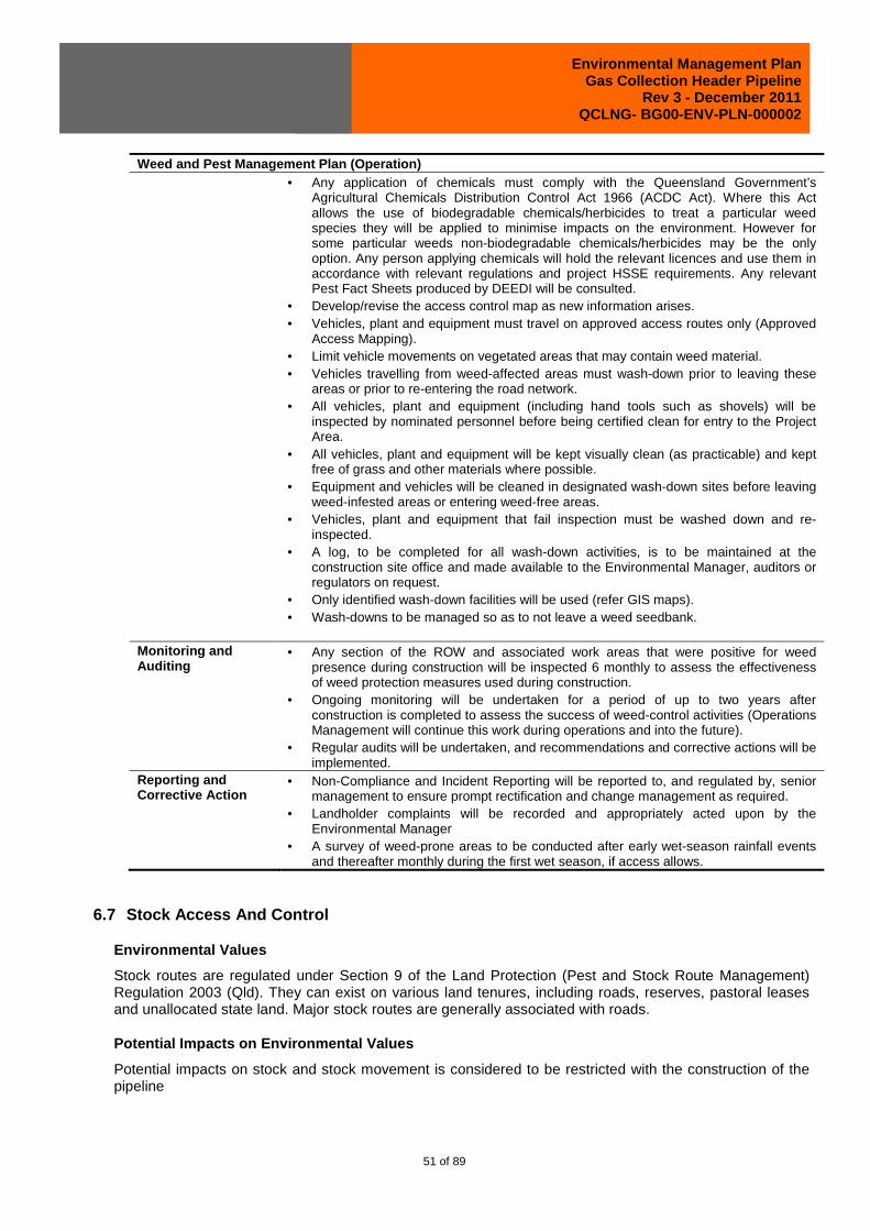
Environmental Management Plan Gas Collection Header Pipeline
Rev 3 - December 2011 QCLNG- BG00-ENV-PLN-000002
51 of 89
Weed and Pest Management Plan (Operation) • Any application of chemicals must comply with the Queensland Government’s
Agricultural Chemicals Distribution Control Act 1966 (ACDC Act). Where this Act allows the use of biodegradable chemicals/herbicides to treat a particular weed species they will be applied to minimise impacts on the environment. However for some particular weeds non-biodegradable chemicals/herbicides may be the only option. Any person applying chemicals will hold the relevant licences and use them in accordance with relevant regulations and project HSSE requirements. Any relevant Pest Fact Sheets produced by DEEDI will be consulted.
• Develop/revise the access control map as new information arises. • Vehicles, plant and equipment must travel on approved access routes only (Approved
Access Mapping). • Limit vehicle movements on vegetated areas that may contain weed material. • Vehicles travelling from weed-affected areas must wash-down prior to leaving these
areas or prior to re-entering the road network. • All vehicles, plant and equipment (including hand tools such as shovels) will be
inspected by nominated personnel before being certified clean for entry to the Project Area.
• All vehicles, plant and equipment will be kept visually clean (as practicable) and kept free of grass and other materials where possible.
• Equipment and vehicles will be cleaned in designated wash-down sites before leaving weed-infested areas or entering weed-free areas.
• Vehicles, plant and equipment that fail inspection must be washed down and re-inspected.
• A log, to be completed for all wash-down activities, is to be maintained at the construction site office and made available to the Environmental Manager, auditors or regulators on request.
• Only identified wash-down facilities will be used (refer GIS maps). • Wash-downs to be managed so as to not leave a weed seedbank.
Monitoring and Auditing
• Any section of the ROW and associated work areas that were positive for weed presence during construction will be inspected 6 monthly to assess the effectiveness of weed protection measures used during construction.
• Ongoing monitoring will be undertaken for a period of up to two years after construction is completed to assess the success of weed-control activities (Operations Management will continue this work during operations and into the future).
• Regular audits will be undertaken, and recommendations and corrective actions will be implemented.
Reporting and Corrective Action
• Non-Compliance and Incident Reporting will be reported to, and regulated by, senior management to ensure prompt rectification and change management as required.
• Landholder complaints will be recorded and appropriately acted upon by the Environmental Manager
• A survey of weed-prone areas to be conducted after early wet-season rainfall events and thereafter monthly during the first wet season, if access allows.
6.7 Stock Access And Control
Environmental Values
Stock routes are regulated under Section 9 of the Land Protection (Pest and Stock Route Management) Regulation 2003 (Qld). They can exist on various land tenures, including roads, reserves, pastoral leases and unallocated state land. Major stock routes are generally associated with roads.
Potential Impacts on Environmental Values
Potential impacts on stock and stock movement is considered to be restricted with the construction of the pipeline

Environmental Management Plan Gas Collection Header Pipeline
Rev 3 - December 2011 QCLNG- BG00-ENV-PLN-000002
52 of 89
Construction
Without adequate control of stock movements, the interaction of stock with pipeline construction may result in:
• Injury or fatality of stock
• Loss or escape of stock
• Restricted access to pasture.
Unrestricted stock movements may also result in damage to gas field infrastructure, which, in turn, may endanger personnel and residents.
Construction activities will be the predominant source of potential impacts on stock. The operation of pipelines is likely to have minimal impact on stock.
Operation
Impacts to stock during operation phase of the pipeline are considered to be negligible.
Stock Access and Control Management Plan
Table 6.12: Stock Access and Control Management Plan
Stock Access and Control Management Plan Policy To minimise the impact on stock movements. Performance criteria
• Where deemed necessary through risk assessment and landholder consultation, stock access will be restricted from Activity sites.
• No stock injured or killed due to pipeline activities. • No complaints from stock farmers.
Implementation strategy
• Identification of stock routes and program of consultation with DERM land management for works within stock routes.
• Where there is a risk to stock safety or pipeline infrastructure, stock may be restricted from accessing certain areas.
• Landholders will be consulted to determine stock movement requirements. • Agreements reached with landholders to restrict access during Activities so that stock is not
unduly disrupted. • Landholder requirements communicated to all relevant QGC personnel. • Upon decommissioning, sites will be rehabilitated to ensure there is no impediment or
potential to cause harm to stock. If infrastructure is to remain, it should, where necessary, exclude stock access with permanent fencing.
Monitoring and auditing
• Stock access observations will be incorporated into the annual audit. • All stock injuries or fatalities attributable to the Project will be recorded and investigated. • All personnel will be aware of landholder requirements and will communicate any breaches
(e.g. fences in need of repair) Reporting and corrective action
• Complaints will be addressed promptly by Land Access Officer and recorded in the incident reporting database if non-compliance with landholder requirements is identified.
• Corrective action will be taken to prevent any repeat of stock injuries or fatalities attributable to the Project.

Environmental Management Plan Gas Collection Header Pipeline
Rev 3 - December 2011 QCLNG- BG00-ENV-PLN-000002
53 of 89
6.8 Surface Water And Groundwater
Environmental Values
Surface Water
The two main catchments traversed by the Gas Collection Pipeline include the Condamine Balonne and the Dawson-Fitzroy. The majority of the pipeline passes through the Condamine-Balonne catchment with the remaining 50 km traversing the upper catchment areas of the Dawson-Fitzroy.
Higher order streams that are to be traversed by the proposed pipeline route include:
• Wambo Creek (Stream Order Category 4)
• Condamine River (Category 7)
• Columboola Creek (Category 4)
• Dogwood Creek (Category 4).
The Gas Collection Header crosses the Condamine River which forms the headwaters of the Ramsar listed Narran Lake Reserve situated approximately 450 km southwest of the Project area.
The DERM Directory of Important Wetlands Dataset indicates that the only nationally wetlands located within the vicinity of the Collection Header are:
• Gums Lagoon located approximately 45 km south of the southern portion of the Gas Collection Header and
• Lake Broadwater approximately 28 km east of the southern portion of the Gas Collection Header.
The Gas Collection Header does not occur within the sub-catchment area of either of these wetlands.
Groundwater
The analysis of bore data has concluded that shallow groundwater along the Gas Collection Header route is expected to be predominantly alluvium associated with major watercourses. Seepage and artesian flow may be encountered in some watercourse beds where aquifers adjoin impermeable rock or in topographically low areas.
Potential Impacts on Environmental Values
Surface water impacts associated with the Gas Collection Header will generally be restricted to the construction activities located in proximity to surface water and/or groundwater features. Impacts associated with the operation of the pipeline are projected to be minimal.
Surface Water
The key impacts to watercourses that can arise from the installation of pipelines are:
• Sedimentation as a result of soil erosion
• Scouring of the streambed due to destabilisation of ground
• Changes to stream flow due to construction
• Pollution of waters due to uncontrolled release of chemicals used in construction.
• Spread of weed species.

Environmental Management Plan Gas Collection Header Pipeline
Rev 3 - December 2011 QCLNG- BG00-ENV-PLN-000002
54 of 89
Construction activities have the potential to lead to sedimentation of watercourses due to erosion as a result of land clearing, soil disturbance and vehicle movements. The cumulative effect of numerous point sources (e.g. disturbed crossings and unstable banks) in an already turbid river system has the potential to impact on sensitive downstream environments and in-stream habitats. For further information please refer to the soil erosion and sedimentation EMP in Section 6.10.
Scouring can lead to the destabilisation of the watercourse. The greatest risk with respect to scouring of creek beds and banks will be the initial wet-season flows prior to successful rehabilitation. There is also a risk that the high discharge velocities that can occur in many of the stream types, and variations in the velocity flow path could lead to the reinstatement stabilisation techniques failing and causing exposure of the pipeline.
During construction there will be temporary interruptions to existing drainage patterns resulting from clearing, grading and trenching activities, diversion drains and bunding. All barriers and/or dams installed during the construction of the pipelines will be removed after construction leaving no permanent flow inhibition.
All pipelines will be designed and constructed consistent with AS2885. Construction environmental management will also be consistent with the requirements of the APIA Code of Environmental Practice for Onshore Pipelines. The majority of the creeks intersected by the pipelines are ephemeral and every effort will be made to construct across these creeks when they are dry.
Due to the separation of catchments transected by the proposed alignment and the closest Ramsar wetlands being more than 450 km from the nearest pipeline, it is considered unlikely that the proposal could have any potential impact on any Ramsar wetland
Groundwater
The investigation identified that the groundwater level in most areas is unlikely to be within 2.5 m of the ground surface and is therefore unlikely to be affected by the pipeline construction and operations
In the event shallower water tables are intersected by the trench, there may be a requirement for dewatering of the trench during construction. This intersection by the trench has the potential to create localised impacts to the groundwater flow patterns. This impact will be temporary due to the short duration of the open trench (approximately three weeks in any one area) and depth of the intrusion.
Surface Water and Groundwater Management Plans
Table 6.13: Surface Water and Groundwater Management Plan (Construction)
Surface Water and Groundwater Management Plan (Constr uction) Operational Policy
To minimise the potential impacts associated with erosion and to prevent the release of contaminants that may adversely affect downstream surface-water quality. To protect the quality of the existing groundwater resources.
Performance Criteria
No release of contaminants to surface waters outside the boundary of Project infrastructure. No failures of sediment and erosion control techniques leading to unacceptable sediment release. Groundwater quality not impacted by construction or during the post construction period.
Implementation Strategy
• Watercourse banks reinstated to prevent scouring. • Watercourse flows and channel crossings not altered. • Erosion- and sediment-control techniques implemented on-site where topography and
landscape require particular management. • No direct or indirect release of contaminants to surface waters as a result of construction
activities. • No accelerated erosion as a result of construction activities. • Where wet crossings are unavoidable, water-quality characteristics measured to be within the
limits set out in the EA. • The crossings will typically be at right angles to the direction of water flow. This will minimise

Environmental Management Plan Gas Collection Header Pipeline
Rev 3 - December 2011 QCLNG- BG00-ENV-PLN-000002
55 of 89
Surface Water and Groundwater Management Plan (Constr uction) scour potential. This will include vehicular and maintenance access.
• Crossings will, where practicable, be undertaken in no- or low-flow conditions during drier months (e.g. April – October).
• Breakers will be installed in trenches close to flowing streams (or in periods of potential inundation) to limit the potential for streamflow or shallow groundwater channelling within the trench.
• Berms will be installed downslope of trench breakers to divert seepage away from the ROW to stable ground.
• Vehicle crossings will be appropriately constructed (e.g. include rock and flume/s) to cater for existing or expected flow conditions.
• Watercourse banks will be reinstated as near as possible to their former profile and stabilised and revegetated as necessary to prevent scouring.
• Existing layers of cobbles and/or coarse gravel in the bed of the watercourse will be reinstated.
• Banks to be reinstated to a slope no steeper than existing site conditions and to a grade compatible with the strength of the site’s soil type.
• Watercourses will be stabilised with, for example, gabions (rock mattresses) or jute matting as required.
• Drainage shall be reinstated to preconstruction direction. • Crossings will be completed promptly. • The disturbance corridor for the bed and bank of watercourses will be the narrowest
practicable for safe construction. However, a wider ROW and work area will be required for watercourses with deep and steep banks in order to install the pipelines at the required depth.
• Where practicable, large trees, particularly hollow-bearing trees, will be retained. Root stock will, wherever practicable, be retained for stabilisation of the banks.
• Riparian vegetation clearing will be kept to the minimum practical for safe construction of the Pipeline and take into consideration other environmental constraints such as soil and felled vegetation stockpiling for rehabilitation.
• Sediment fences will be installed between the creek and the construction area when wet weather is expected.
• The Construction Supervisor will be vigilant of flood warnings and, where necessary, action will be taken in accordance with the Emergency Response Plan.
• Any trench water will be pumped out to stable ground well away from any watercourse. • Where trench de-watering is required at a watercourse, the water will be discharged through
a settlement basin to minimise turbidity. Hydrotest Water • Hydrotest water is to be sourced only from authorised sources under permits issued by the
regulatory authority. • The source of hydrostatic test water shall be approved in advance by the Environmental
Manager. • If required, relevant permits to draw water from State Resources shall be obtained. • Where water is to be transferred from one catchment to another in-line filters will be used. • Pipeline sections crossing water bodies (trenchless crossings in particular) will be tested prior
to installation. • Inspection of all pipeline section welds or hydrotesting of pipeline sections before installation
under water bodies will be performed in accordance with construction specifications/procedures.
• Disposal of hydrotest water will be in accordance with relevant environmental authority conditions.
Compressor Station • Bunding and sediment fences will be installed to prevent any contamination of surface waters • Stormwater falling outside bunded areas will be drained away from process areas and
systems for managing contaminated stormwater into natural drainage points around the site. • Grade and slope site to ensure stormwater drains away from process equipment. • Fit bunded areas with drains normally closed so that stormwater can be drained to the on-site

Environmental Management Plan Gas Collection Header Pipeline
Rev 3 - December 2011 QCLNG- BG00-ENV-PLN-000002
56 of 89
Surface Water and Groundwater Management Plan (Constr uction) evaporation pond.
• Direct bunded drains into an interceptor pit. • Remove unnecessary water traps to prevent mosquito-breeding areas. • Maintenance and cleaning of vehicles to be completed at off-site facilities where possible. If
completed on-site, activities will be at locations where the potential for the release of contaminants to waters or stormwater systems is minimised.
Monitoring and Auditing
• During construction, the entire length of the easement will be regularly inspected to assess the effectiveness of protection measures, with frequent assessment of the effectiveness of the management of watercourse environments.
• Water quality will be monitored upstream and downstream of the construction area where a discharge occurs
• Records will be maintained of all releases to waters including the location, frequency of discharge and monitoring results.
Reporting and Corrective Action
• The following will be reported regularly: 1. Contractor compliance with approved erosion and sediment control plan. 2. Incidents of erosion or surface water contamination. 3. Results of routine inspections.
• The following are classified as incidents relating to surface-water management: 1. Erosion and sediment control plan not prepared and/or implemented. 2. Breach in integrity of bunds / erosion controls 3. Any temporary sediment basins demonstrating significant reduced available volume. 4. Insufficient housekeeping to prevent general rubbish and contaminants entering
stormwater and runoff from the site. • Should an incident/failure to comply occur, the following corrective actions could be
considered: 1. Repair soil erosion and sediment controls. 2. Repair stormwater controls. 3. Contain and remedy or dispose of contaminated material/s. 4. Clean out temporary sediment basins allowing for dissipation of concentrated flows. 5. Improve level of housekeeping. 6. Review the relevant plans.
• Landholder complaints will be recorded and appropriately acted upon by the Environmental Manager.
Table 6.14: Surface Water and Groundwater Management Plan (Operation)
Surface Water and Groundwater Management Plan (Operation) Management Policy
To minimise the potential impacts associated with erosion and to prevent the release of contaminants that may adversely affect downstream surface-water quality. To protect the quality of the existing groundwater resources.
Performance Objectives
• No release of contaminants to surface waters outside the boundary of Project infrastructure. • No failures of sediment and erosion control techniques leading to unacceptable sediment
release. • Groundwater quality not impacted by post-construction activities.
Implementation strategy
Compressor Station • Drain stormwater falling outside bunded areas away from process areas and systems for
managing contaminated stormwater into natural drainage points around the site. • Grade and slope site to ensure stormwater drains away from process equipment. • Fit bunded areas with drains normally closed so that stormwater can be drained to the on-
site evaporation pond. • Direct bunded drains into an interceptor pit. • Remove unnecessary water traps to prevent mosquito-breeding areas. • Maintenance and cleaning of vehicles to be completed at off-site facilities where possible. If
completed on-site, activities will be at locations where the potential for the release of contaminants to waters or stormwater systems is minimised.
Pipeline

Environmental Management Plan Gas Collection Header Pipeline
Rev 3 - December 2011 QCLNG- BG00-ENV-PLN-000002
57 of 89
Surface Water and Groundwater Management Plan (Operation) • No visible evidence of:
− Significant erosion following high rainfall. − Damage or failure of stormwater control devices or systems. − Collapse/subsidence of banks at nearby watercourse crossings or notable increases in
flow levels or flooding associated with local waterways. − Subsidence or exposure of pipeline.
• Ensure run-off is distributed to the greatest extent possible, particularly in critical areas (e.g. adjacent to watercourses, highly erosive soils) to stable ground by the use of turn-off drains, contour banks, etc.
• Ensure ground stabilisation, either by vegetation cover or compaction, to all unsealed areas within the boundary fence at above-ground facilities.
• Monitor and maintain stormwater run-off control devices (e.g. spoon drains, diffusers, berms) at above-ground facilities.
Monitoring • Periodic inspections to visually assess presence and effectiveness of run-off control structures.
Reporting and Corrective Action
• Rectify deficient run-off control structures.
6.9 Topography
Environmental Values
The Gas Collection Header is predominantly situated on flat and undulating plains. No steep sloping areas that are expected to place any constraints on pipeline construction occur along the proposed route.
Potential Impacts On Environmental Values
The pipeline route has been selected to avoid or minimise impacts associated with topographical and geomorphology constraints. It is expected that he construction of the Gas Collection Header will require minimal landform modification although crossing of significance with high river banks will require careful management.
Land topography will not be impacted during the operation of the pipeline.
Topography Maintenance Management Plan
Table 6.15: Topography Maintenance Management Plan
Topography Maintenance Management Plan Policy To minimise impacts to topography. Performance criteria
• Minimise sediment and erosion release from areas where topography is altered. • Consultation with stakeholders regarding topography following decommissioning. • Where practicable, sites are returned to their original profile upon decommissioning.
Implementation strategy
• The Activity area will be returned to original or stable contours, re-establishing surface drainage lines and other land features.
• Where areas of significant topographic restriction cannot be avoided: − Limit access of specialist heavy machinery. − Careful excavation. − Adopt special measures to build access tracks with appropriate grade. − Development sites with significant topographic restrictions will be subject to a detailed
site development plan. Monitoring and auditing:
• Development sites will be inspected to ensure compliance with site development plans.
Reporting and corrective action
• Instances of non-compliance will be investigated and corrective actions taken.

Environmental Management Plan Gas Collection Header Pipeline
Rev 3 - December 2011 QCLNG- BG00-ENV-PLN-000002
58 of 89
6.10 Soil Erosion And Sediment Control
Environmental Values
The majority of the first 150 km of the Gas Collection Header is comprised of shallow infertile texture contrast soils (Sodosols) with shallow topsoil (typically 10-20 cm thick) and a sharp transition to a medium to heavy clay subsoil that is sodic and highly dispersive.
Between KPs 79 to 89 the Gas Collection Header passes through predominantly deep cracking clay soils (Vertosols) that are valued for cropping and intensive and pasture production. Melonholes (gilgai) which are commonly associated with these deep cracking soils were found to be common in the area.
The remainder of the route (i.e. KP 140-194) predominantly occurs in shallow dark and brown cracking clay (Vertosol) soils with a generally low to moderate erosion risk.
Measures to avoid strategic cropping areas have been incorporated into the route planning for the project. Thus, only minor areas that are suitable for intensive cropping will be affected by the project.
The majority of the area transected by the pipeline is currently relatively stable with only short sections exhibiting significant existing erosion levels, primarily in the form of gully erosion. These significant existing erosion areas are mainly located around local drainage channels (i.e. in the vicinity of Wambo and Columboola Creeks) where previous disturbances have exposed highly dispersive sodic subsoils prone to gully and tunnel erosion (often associated with the effects of existing adjacent infrastructure such as roadways).
Potential Impacts on Environmental Values
The most significant soil and terrain impacts are generally associated with the construction of the pipeline. Impacts associated with the operation of the pipeline are expected to be minimal.
Construction
Construction activities which have the potential to impact on the soils and terrain of the Project area include:
• Pipeline route clearing and excavation activities
• Development of additional access tracks
• Establishment and operation of any construction work areas
• Establishment of stockpiling areas for pipe.
Without appropriate mitigation measures in place there is a potential that construction activities could instigate or exacerbate soil erosion that could lead to the reduction of land capability and impact water quality values downstream.
The instigation or exacerbation of gully and tunnel erosion in proximity to drainage lines will be a potential risk associated with pipeline construction. Where shallow texture contrast soils are found in steeper terrain near the central and northern sections of the Gas Collection Header, the potential for erosion will be significant if not properly managed.
The cracking clay soils primarily associated with (former) brigalow vegetation also have significantly dispersive sodic subsoils that will require careful management strategies. However, these soils will be more conducive to vegetative rehabilitation due to the inherent fertility levels and better soil structure.
With the implementation of the erosion control measures as discussed in the Soil Erosion and Sediment Control Management Plan the elevated soil erosion potential risk would only exist for short periods. In these
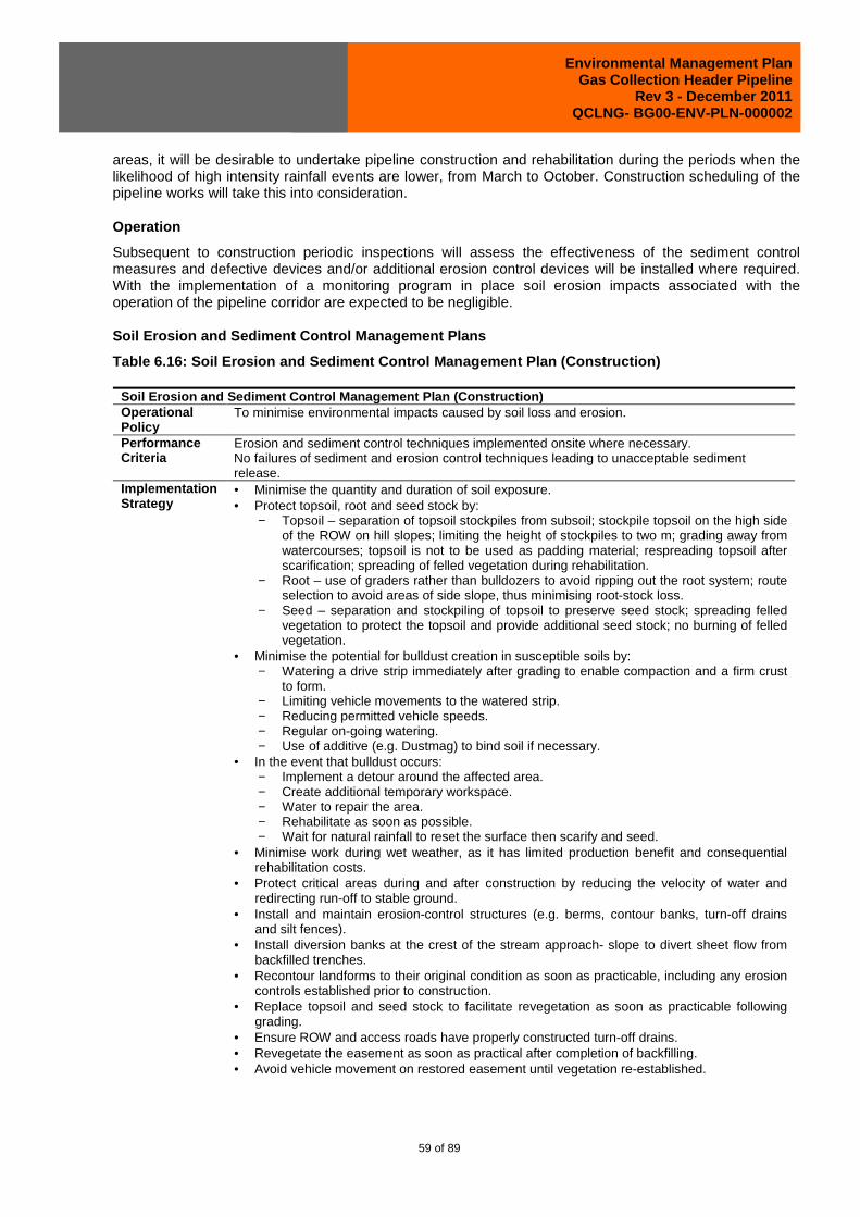
Environmental Management Plan Gas Collection Header Pipeline
Rev 3 - December 2011 QCLNG- BG00-ENV-PLN-000002
59 of 89
areas, it will be desirable to undertake pipeline construction and rehabilitation during the periods when the likelihood of high intensity rainfall events are lower, from March to October. Construction scheduling of the pipeline works will take this into consideration.
Operation
Subsequent to construction periodic inspections will assess the effectiveness of the sediment control measures and defective devices and/or additional erosion control devices will be installed where required. With the implementation of a monitoring program in place soil erosion impacts associated with the operation of the pipeline corridor are expected to be negligible.
Soil Erosion and Sediment Control Management Plans
Table 6.16: Soil Erosion and Sediment Control Management Plan (Construction)
Soil Erosion and Sediment Control Management Plan (Construction) Operational Policy
To minimise environmental impacts caused by soil loss and erosion.
Performance Criteria
Erosion and sediment control techniques implemented onsite where necessary. No failures of sediment and erosion control techniques leading to unacceptable sediment release.
Implementation Strategy
• Minimise the quantity and duration of soil exposure. • Protect topsoil, root and seed stock by:
− Topsoil – separation of topsoil stockpiles from subsoil; stockpile topsoil on the high side of the ROW on hill slopes; limiting the height of stockpiles to two m; grading away from watercourses; topsoil is not to be used as padding material; respreading topsoil after scarification; spreading of felled vegetation during rehabilitation.
− Root – use of graders rather than bulldozers to avoid ripping out the root system; route selection to avoid areas of side slope, thus minimising root-stock loss.
− Seed – separation and stockpiling of topsoil to preserve seed stock; spreading felled vegetation to protect the topsoil and provide additional seed stock; no burning of felled vegetation.
• Minimise the potential for bulldust creation in susceptible soils by: − Watering a drive strip immediately after grading to enable compaction and a firm crust
to form. − Limiting vehicle movements to the watered strip. − Reducing permitted vehicle speeds. − Regular on-going watering. − Use of additive (e.g. Dustmag) to bind soil if necessary.
• In the event that bulldust occurs: − Implement a detour around the affected area. − Create additional temporary workspace. − Water to repair the area. − Rehabilitate as soon as possible. − Wait for natural rainfall to reset the surface then scarify and seed.
• Minimise work during wet weather, as it has limited production benefit and consequential rehabilitation costs.
• Protect critical areas during and after construction by reducing the velocity of water and redirecting run-off to stable ground.
• Install and maintain erosion-control structures (e.g. berms, contour banks, turn-off drains and silt fences).
• Install diversion banks at the crest of the stream approach- slope to divert sheet flow from backfilled trenches.
• Recontour landforms to their original condition as soon as practicable, including any erosion controls established prior to construction.
• Replace topsoil and seed stock to facilitate revegetation as soon as practicable following grading.
• Ensure ROW and access roads have properly constructed turn-off drains. • Revegetate the easement as soon as practical after completion of backfilling. • Avoid vehicle movement on restored easement until vegetation re-established.

Environmental Management Plan Gas Collection Header Pipeline
Rev 3 - December 2011 QCLNG- BG00-ENV-PLN-000002
60 of 89
Soil Erosion and Sediment Control Management Plan (Construction) • Inspect the ROW and maintain erosion and sediment controls as necessary during and after
construction, until stabilisation is achieved. Monitoring and Auditing
• During construction, the entire length of the easement will be regularly inspected to assess the effectiveness of erosion-protection measures, with particular attention to sensitive locations.
• The inspection of sediment controls should focus on integrity of: − Topsoil stockpiles − Sediment fencing condition − ROW diversions channels (ensure they are not being eroded or “washed out”) − Drainage channels and creeks.
• Additional inspections will be undertaken following high rainfall (i.e. >25 mm per day). Reporting and Corrective Action
• The following will be reported regularly: 1. Contractor compliance with approved erosion and sediment control plan. 2. Incidents of erosion or surface water contamination. 3. Results of routine inspections.
• The following are classified as incidents relating to surface-water management: 1. Erosion and sediment control plan not prepared and/or implemented. 2. Breach in integrity of bunds / erosion controls 3. Any temporary sediment basins demonstrating significant reduced available volume. 4. Insufficient housekeeping to prevent general rubbish and contaminants entering
stormwater and runoff from the site. • Should an incident/failure to comply occur, the following corrective actions could be
considered: 1. Repair soil erosion and sediment controls. 2. Repair stormwater controls. 3. Contain and remedy or dispose of contaminated material/s. 4. Clean out temporary sediment basins allowing for dissipation of concentrated flows. 5. Improve level of housekeeping. 6. Review the relevant plans.
• Landholder complaints will be recorded and appropriately acted upon by the Environmental Manager
Table 6.17: Soil Erosion and Sediment Control Management Plan (Operation)
Soil Erosion and Sediment Control Management Plan (Ope ration) Policy To minimise environmental impacts caused by soil loss and erosion. Performance Objectives
Erosion and sediment control techniques implemented onsite where necessary. No failures of sediment and erosion control techniques leading to unacceptable sediment release.
Implementation strategy
No visible evidence of: − Significant erosion during operations (i.e. significantly above that of adjacent lands). − Significant erosion following excavation or extreme rainfall. − Significant changes to ground level, drainage patterns, etc. which may indicate soil
erosion and sedimentation. − Damage or failure of erosion/sediment control devices. − Collapse/subsidence of banks at nearby watercourse crossings. − Subsidence or exposure of pipeline.
• Install, maintain and monitor erosion and sediment control devices (e.g. berms, silt fences, jute matting) so that ground is stable and vegetation cover is maintained.
• Gravel permanent access roads to above-ground facilities. • Ensure ground stabilisation, either by vegetation cover or compaction, to all unsealed areas
within the boundary fence at above-ground facilities. • Install sediment fencing around active erosion adjacent to watercourses, as needed, to
keep areas stable. • Monitor and maintain storm water run-off control devices (e.g. spoon drains, diffusers,
berms) at above-ground facilities.

Environmental Management Plan Gas Collection Header Pipeline
Rev 3 - December 2011 QCLNG- BG00-ENV-PLN-000002
61 of 89
Soil Erosion and Sediment Control Management Plan (Ope ration) Monitoring and Auditing
• Visual assessment of presence and effectiveness of erosion, sediment and run-off control structures during periodic inspections.
• Inspection of watercourse crossings after major rainfall events (e.g. >25 mm per day). • Re-instate or repair defective erosion, sediment and run-off control devices. • Review stormwater management techniques as required.
Reporting and Corrective Actions
• Install additional erosion, sediment or run-off control measures where inspections indicate remedial action is required.
• Utilise latest techniques as they become known where standard techniques continually fail to meet performance criteria.
6.11 Soil Contamination
Environmental Values
Pipelines will pass through rural land that has been predominantly used for grazing. A risk-based approach was used during the route selection to avoid areas of known or likely contamination. This process will continue during the route refinement and detailed design phase and in consultation with landholders.
After reviewing past land uses of affected land parcels, after detailed soil surveys along the route and after negotiation with landholders during the route selection process no contaminated sites have yet been identified.
Notwithstanding this, it is recognised that there still remains a remote possibility that contaminated lands will be encountered along the pipeline route. The following observation and experience were taken into account:
• Many rural properties do not have access to waste collection services and in the past waste has often been disposed of on site. Wastes include domestic waste, animal carcasses, chemical containers and other materials such as asbestos sheeting
• Burning wastes, particularly treated or painted timber, can release heavy metals into the soil. No such contaminated areas were identified during field work and site inspections, but such disposal sites may be encountered along the route during development
• Rural properties may also have operational or abandoned animal dips which contain pesticide residues and heavy metals
• The preferred route crosses rail tracks and major roadways at various points. Hydrocarbon contamination, including coal fines and herbicide residues associated with weed control may be potential problems at such points. Where asbestos brake linings have been used on trains, dust and fibres from these can accumulate in the soil adjacent to tracks, also causing land contamination.
Negotiations with landholders in relation to the pipeline easements will continue throughout the final alignment selection phase to identify any known stock dips or waste disposal areas.
Potential Impacts On Environmental Values
If contaminated land is encountered during the construction phase there may be a risk to construction personnel and the wider public. There is also a risk that the release of contaminated material into the environment beyond the work area will cause environmental harm and/or affect public health.
There is also a risk of localised land contamination from Project-related activities associated with the handling and use of fuels and chemicals. Pipeline projects generally involve relatively small quantities of chemicals and the volume of any potential spill would be low. The construction and operation of the Gas Collection Header is no different.

Environmental Management Plan Gas Collection Header Pipeline
Rev 3 - December 2011 QCLNG- BG00-ENV-PLN-000002
62 of 89
Soil Contamination Management Plans
Table 6.18: Soil Contamination Management Plan (Construction)
Soil Contamination Management Plan (Construction) Operational Policy
No contamination of soils arising from Project activities. To manage any pre-existing contaminated soils such that extent of contamination is not exacerbated by Project activities.
Performance Criteria
• Project sites not added to Queensland Contaminated Land Register (CLR). • No release of hazardous substance or dangerous goods to soil. • Identify all pre-existing contaminated soils likely to be impacted by Project activities. • Where pre-existing contaminated soils are identified, and disturbance by Project activities is
unavoidable, develop and implement appropriate management strategies. Implementation Strategy
• Trenching Supervisor will be instructed in process for handling previously unidentified contaminated areas (e.g. dip, waste pit) or acid sulfate soil in the event that any such areas are uncovered during trenching. These will include: − Cessation of trenching at the location. − Relocation and recommencement of trenching 50m ahead. − Advise Environment Manager for notification to regulatory authorities. − Have site assessed in accordance with the relevant DERM Guidelines – Draft Guideline
for the Assessment and Management of Contaminated Land in Queensland, Department of Environment, May 1998 where contamination is confirmed.
− Initiate appropriate remedial action based on the assessment. This may include deviating around the site.
• Storage of all fuels and chemicals will comply with relevant legislation governing the storage and handling of materials that may adversely impact the environment if released (i.e. Queensland Dangerous Goods Safety Management Regulations, 2001).
• Appropriate spill-containment facilities for all chemicals and fuel storage areas will be established in accordance with AS 1940 and AS 3780.
• A hazardous materials register detailing the location and quantities of hazardous substances will be established and maintained, including details of storage, use and disposal.
• Personnel will be inducted and trained in safe work practices to minimise the risk of spillage.
• If an area of contamination is reported, the cause will be identified and the area of contamination contained. The impact may be contained by isolating the source or implementing controls around the affected site.
• Remediation of contaminated land will use the most appropriate available method to achieve required commercial/industrial guideline validation results.
• Validation sampling of any remediated area will be used to establish the site as “clean” in line with the relevant DERM Contaminated Land and National Environment Protection Measure (NEPM) Guidelines.
• Wastes will be classified, transported and disposed of in accordance with Queensland Environmental Protection (Waste Management) Policy 2000 and Environmental Protection (Waste Management) Regulation 2000.
Monitoring and Auditing
• The integrity of storage facilities for hazardous materials and wastes and bunded areas will be routinely inspected.
Reporting and Corrective Action
• Regular audits and reviews of this EMP will be undertaken and recommendations and corrective actions implemented.
• Daily or weekly work reports (as appropriate) shall be recorded and reviewed by each supervisor or manager.
• Non-Compliance and Incident Reporting will be closed out by senior management to ensure prompt rectification and change management as required.
• The owner and construction contractor will maintain records of all monitoring and auditing activities and report results to the Environmental Manager at agreed intervals.

Environmental Management Plan Gas Collection Header Pipeline
Rev 3 - December 2011 QCLNG- BG00-ENV-PLN-000002
63 of 89
Table 6.19: Soil Contamination Management Plan (Operation)
Soil Contamination Management Plan (Operation) Operational Policy
No contamination of soils arising from Project activities. To manage any pre-existing contaminated soils such that extent of contamination is not exacerbated by Project activities. Minimise, where practicable, contamination of soils by hydrotest water.
Performance Criteria
• Where pre-existing contaminated soils are identified, and disturbance by Project activities is unavoidable, continued implementation of appropriate management strategies.
Implementation Strategy
• Storage of all fuels and chemicals will comply with relevant legislation governing the storage and handling of materials that may adversely impact the environment if released (i.e. Queensland Dangerous Goods Safety Management Regulations, 2001)
• Appropriate spill-containment facilities for all chemicals and fuel storage areas will be established (in accordance with AS 1940 and AS 3780).
• A hazardous materials register detailing the location and quantities of hazardous substances will be established and maintained, including details of storage, use and disposal.
• Personnel will be inducted and trained in safe work practices to minimise the risk of spillage. • If an area of contamination is reported, the cause will be identified and the area of
contamination contained. The impact may be contained by isolating the source or implementing controls around the affected site.
• Remediation of contaminated land will use the most appropriate available method to achieve required commercial/industrial guideline validation results.
• Validation sampling of any remediated area will be used to establish the site as “clean” as per the relevant DERM Contaminated Land and National Environment Protection Measure (NEPM) Guidelines.
• Monitoring and Auditing
• Regular monitoring of groundwater and surface water to ensure any releases are identified and remediated as soon as practicable.
• The integrity of storage facilities for hazardous materials and wastes and bunded areas will be routinely inspected.
Reporting and Corrective Action
• Regular audits and reviews of this EMP will be undertaken and recommendations and corrective actions implemented.
• Daily or weekly monitoring reports (as appropriate) shall be recorded and reviewed by each supervisor or manager.
• Non-Compliance and Incident Reporting will be closed out by senior management to ensure prompt rectification and change management as required.
• The Environmental Manager will maintain records of all monitoring and auditing activities and report results to the Environmental Manager at agreed intervals.
6.12 Community
Environmental Values
The Gas Collection Header traverses mainly through land that falls within Western Downs Regional Council. Townships within this area have a strong sense of community and value the friendly nature of the area as well the country lifestyle and the availability of services and infrastructure. There is strong social capital in the area, with an above average number of the population involved in some form of volunteer work.
Communities in this area desire a balance between community lifestyle, development and the environment. They recognise the importance of development in stimulating growth in the area and seek sustainable opportunities that will enhance the character and heritage of the community whilst preserving its natural resources.

Environmental Management Plan Gas Collection Header Pipeline
Rev 3 - December 2011 QCLNG- BG00-ENV-PLN-000002
64 of 89
The most common liveability concern arises from the condition of road transport infrastructure within the area.
Potential Impacts On Environmental Values
It is likely that there will be impacts on the local community as a result of the construction and operation of the Gas Collection Header. Potential impacts are likely to include the following:
• Labour force and employment impacts within the area;
• Demographic impacts;
• Housing impacts;
• Social infrastructure and access impacts;
• Community health and safety impacts;
• Property and land use impacts; and
• Lifestyle, amenity and community values impacts.
A detailed Social Impact Assessment has been undertaken as part of the EIS process, and a Draft Social Impact Management Plan has been prepared. The Draft Social Impact Management Plan document provides a detailed analysis of the potential impacts of the construction and operation of the Collection Header.
Community Management Plan
Table 6.20: Community Management Plan
Community Management Plan Policy • QGC’s commitment to social sustainability in the Project area is expressed in two
fundamental principles: • avoiding or mitigating negative impacts on social values • enhance Project benefits and community development throughout the Project area.
Performance criteria
• Minor community impacts as a result of the construction and operation of the Collection Header
• Positive legacy in the area as a result of investment in infrastructure upgrades, employment opportunities, social infrastructure etc.
• Compliance with the Draft Social Impact Management Plan Implementation strategy
• Local recruitment and training strategy is paramount
− Institutional and community partnerships to be developed for local skills development, including o Identifying local labour force availability and skill set match to project requirements o A particular focus on employment programs with Indigenous people o Targeting Project recruitment programs, skills development, public information
strategy to increase local and regional employment and job placement programs to include young people and unemployed people
o Invest in local training and skills development program
• Source part of skilled workforce from outside of local region • Ensure relevant agencies are aware of project development and likely consequent population
growth • Invest in community capacity and social infrastructure through QGC Community
Development Fund • Integration program required and support for social infrastructure • Provision of workers’ camps for majority of the Gas Field construction workforce
− Develop a housing management and accommodation strategy − Develop a camp management strategy
• Investment in housing production partnerships including affordable housing. The Project

Environmental Management Plan Gas Collection Header Pipeline
Rev 3 - December 2011 QCLNG- BG00-ENV-PLN-000002
65 of 89
Community Management Plan intends to make a contribution to affordable housing for low-income people in the Dalby region, to ensure that the most vulnerable community members are not excessively impacted by indirect population demands.
• Liaison with community and private child care providers to monitor Project demand • Augment existing health services by providing a doctor for camp residents for the peak
average construction period − Work with other stakeholders to increase local capacity for rural medicine and health
service provision − Project will have its own medievac arrangements. − Liaison with local and regional emergency services
• Invest in the expansion of community based re-settlement programs and family support services (such as counselling, parenting support, playgroups, and personal development and youth programs). Such investment could enhance overall community capacity and resilience.
• Invest in the development of local human service provider capacity to support people with culturally diverse needs (including linguistic and cross cultural awareness).
• Undertake community development initiatives targeting behaviour awareness and management for workers and local young men and women, and assertiveness training for local young men and women.
• Maximise local employment where possible − Remote location of workers camps where possible − Project will support community services which are critical to managing such impacts.
• QGC's Social Performance Plan and Social Investment Strategy will contribute to local community capacity and social infrastructure upgrades.
• Land access and community relations procedures in place, with contractors required to perform to BG Group standards. − Land access and compensation negotiations under way with each property owner
directly affected by the project. − Temporary impacts will be negotiated and suitable arrangements will be made with
landholders. − Public grievance procedures in place
• Grievance procedures in place Project driving standards and traffic management measures will be implemented.
• To reduce risks of accident, mitigation will focus on project driving standards and health and safety awareness in communities.
• Project infrastructure will be located to reduce and mitigate impacts on dwellings, towns and sensitive receptors. − Mitigation strategies relevant to each receptor will be developed on a site by site basis,
including mitigation at source and at receptor. − Transparent approach in monitoring noise.
• Avoid and minimise Project activity on GQAL − Land access negotiations and compensation will be used to mitigate these impacts
• Avoidance of forests of environmental significance where possible − Rehabilitation of land where possible − Likely development of forestry using associated water
• Stock crossing points will be installed. • Consultations with landholders will be undertaken to discuss management of irrigation
systems • Weed and seed transfer related mitigation impacts discussed in the weed and pest
management plan • Project staff will follow correct land access procedures of closing fence gates to avoid cattle
from going across their designated land. Monitoring and auditing
• As per the Draft Social Impact Management Plan
Reporting and corrective action
• Non-compliance and reported incidents will be investigated and closed out. • QGC and EPC contractor will maintain records of complaints received and corrective actions
undertaken to prevent recurrence.
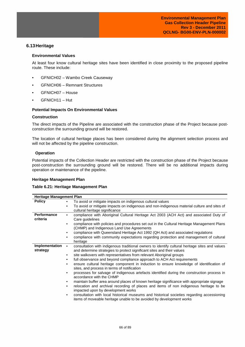
Environmental Management Plan Gas Collection Header Pipeline
Rev 3 - December 2011 QCLNG- BG00-ENV-PLN-000002
66 of 89
6.13 Heritage
Environmental Values
At least four know cultural heritage sites have been identified in close proximity to the proposed pipeline route. These include:
• GFNICH02 – Wambo Creek Causeway
• GFNICH06 – Remnant Structures
• GFNICH07 – House
• GFNICH11 – Hut
Potential Impacts On Environmental Values
Construction
The direct impacts of the Pipeline are associated with the construction phase of the Project because post-construction the surrounding ground will be restored.
The location of cultural heritage places has been considered during the alignment selection process and will not be affected by the pipeline construction.
Operation
Potential impacts of the Collection Header are restricted with the construction phase of the Project because post-construction the surrounding ground will be restored. There will be no additional impacts during operation or maintenance of the pipeline.
Heritage Management Plan
Table 6.21: Heritage Management Plan
Heritage Management Plan Policy • To avoid or mitigate impacts on indigenous cultural values
• To avoid or mitigate impacts on indigenous and non-indigenous material culture and sites of cultural heritage significance
Performance criteria
• compliance with Aboriginal Cultural Heritage Act 2003 (ACH Act) and associated Duty of Care guidelines
• compliance with policies and procedures set out in the Cultural Heritage Management Plans (CHMP) and Indigenous Land Use Agreements
• compliance with Queensland Heritage Act 1992 (QH Act) and associated regulations • compliance with community expectations regarding protection and management of cultural
heritage Implementation strategy
• consultation with indigenous traditional owners to identify cultural heritage sites and values and determine strategies to protect significant sites and their values
• site walkovers with representatives from relevant Aboriginal groups • full observance and beyond compliance approach to ACH Act requirements • ensure cultural heritage component in induction to ensure knowledge of identification of
sites, and process in terms of notification • processes for salvage of indigenous artefacts identified during the construction process in
accordance with the CHMP • maintain buffer area around places of known heritage significance with appropriate signage • relocation and archival recording of places and items of non indigenous heritage to be
impacted upon by development works • consultation with local historical museums and historical societies regarding accessioning
items of moveable heritage unable to be avoided by development works

Environmental Management Plan Gas Collection Header Pipeline
Rev 3 - December 2011 QCLNG- BG00-ENV-PLN-000002
67 of 89
Heritage Management Plan Monitoring and auditing
• monitoring of sensitive areas by representatives from the relevant Traditional Owner groups during clearing and grading and / or trenching operations and during preliminary ground disturbance activities group in accordance with ACH Act Duty of Care guidelines
• monitoring by QGC of compliance with QH Act. • monitoring by contractors and construction managers to ensure detailed design and
construction planning avoids or mitigates impacts on non-indigenous cultural heritage Reporting and corrective action
• new indigenous heritage sites identified during construction phase will be reported to DERM for inclusion in the Aboriginal and Torres Strait Islander Register and Database
• notify the Queensland Police if human remains are discovered to determine whether the remains are ancient and/or indigenous. If determined to be indigenous, the DERM procedure on the discovery, handling and management of human remains under the provisions of the ACH Act will apply.
• notify the DERM of any discoveries under s.89 of the QH Act
6.14 Landscape And Character Maintenance
Environmental Values
The routes for pipelines proposed as part of the Pipeline Component of the QCLNG Project traverse predominantly freehold lots. However, several leasehold areas and reserves are located along the proposed routes. Proposed routes have been selected to avoid major mining leases (ML) or mining lease applications (MLA).
Existing infrastructure such as roads, power lines, railways and other pipelines either intersect or occur in proximity to the proposed pipeline route. The depth of the pipe under road crossings will be a minimum depth of 1.2m below the bottom of table drains. Pipeline depth under rail crossings will be a minimum of 2 m under the full width of the rail reserve and trench-less techniques will be used.
The pipeline routes has been planned to largely avoid residential areas. The key residential and recreational areas along the pipeline routes are associated with the townships.
Potential Impacts On Environmental Values
Construction
The pipelines will not impose any long-term restrictions on the current use of identified land tenure along the routes.
The main impact of the Project in terms of land use will be primarily during the construction program when land used for activities such as agriculture and grazing will be temporarily restricted over the ROW.
Several quarries and extractive industries have been identified within 5 km of the proposed pipeline route. Land overlain by mining permits, claims and leases is subject to the provisions of the Minerals Resources Act 1989 (Qld) (MR Act). QGC has considered the relevant provisions of the MR Act in determining the current proposed alignment of the Collection Header. Location of the pipeline alignments has been, and will continue to be, negotiated with the relevant operators to help ensure that, where practicable, the installed pipeline will have limited adverse impacts on future extraction activities and to ensure that extraction activities have no adverse impacts on the integrity of the pipeline.
Where commercially viable quantities of timber are identified for removal, further discussions will be held with relevant regional groups within DERM Forest Products, including the Manager, Western Forest Management Area (FMA) and Manager, Cypress FMA. The Project schedule is unlikely to allow for negotiation or retrieval of commercial timber with DERM at least 18 months before construction begins.

Environmental Management Plan Gas Collection Header Pipeline
Rev 3 - December 2011 QCLNG- BG00-ENV-PLN-000002
68 of 89
Operation
Once the pipeline is operational, land use impact will be minimal comprising periodic inspections and maintenance of the route by QGC.
Landscape and Character Maintenance Management Plan
Table 6.22: Landscape and Character Maintenance Management Plan
Landscape and Character Maintenance Management Plan Policy To minimise the impact on environmental and community values from the location and
construction of infrastructure. Performance criteria
• Respond to all complaints regarding impacts on environmental and community values and, where feasible, implement mitigation measures.
• Consultation with potentially affected stakeholders. • Evidence that decision criteria for location of infrastructure includes consideration of
environmental and community values. Implementation strategy
• QGC will aim to minimise the impact on rural lifestyle values through: − appropriate siting of Pipeline infrastructure − progressive rehabilitation of disturbed areas − direct liaison with potentially affected stakeholders.
• Mitigation measures to reduce impacts on landscape character, land use and existing infrastructure include: − ensuring appropriate buffers are maintained between the Pipeline and existing and
planned development, or where this is not practicable, ensuring pipeline design meets the safety requirements for developed areas
− ensuring appropriate discussions with landholders and occupants in relation to the provision of access for pipeline construction and ongoing maintenance during operation
− liaising with mining permit, claim or lease holders to determine the most appropriate alignment based on current and future needs and ensuring that existing legislation has been considered
− consultation with infrastructure providers (e.g. regional councils for water pipelines, telecommunications providers for fibre optic cables) and “Dial Before You Dig” queries to identify other underground infrastructure
− minimising impacts on Good Quality Agricultural Land (GQAL) by following fence lines where practicable and/or minimising construction and camps in areas designated as Class A agricultural land or land used for cropping
− ensuring that associated work areas are minimised in environmentally sensitive areas, state forest, and riparian zones
− ensuring minimal impact on major transport corridors by boring under all sealed State controlled roads and railway lines
− ensuring that the Pipeline is appropriately signposted − ensuring appropriate notification and management of noisy and dusty activities
particularly in proximity to residential areas, roads and schools. • Identify all public and private infrastructure within the Project area prior to construction. • Seek broad consent from all Native Title claimants for all current and future acts required to
construct and operate the pipeline. • Where commercially viable quantities of millable timber are identified with DERM QGC will
provide sufficient lead time for DERM to arrange for salvage of this timber. • Pipeline infrastructure will not be established, without prior consultation with potentially
impacted parties, in areas where quarrying activities occur. • All precautions will be taken to minimise damage to farm infrastructure. • Individual access and entry protocols will be agreed and documented through close
consultation with all landholders. Care will be taken to minimise disruption to existing lifestyles of landholders.
• The ROW will be progressively rehabilitated.

Environmental Management Plan Gas Collection Header Pipeline
Rev 3 - December 2011 QCLNG- BG00-ENV-PLN-000002
69 of 89
Landscape and Character Maintenance Management Plan Monitoring and auditing:
• A record of all instances of non-compliance with this plan will be maintained. • Location and design of infrastructure will be subject to a rigorous selection process where
potential conflicts with existing land use and landscape character are identified. • Actual development sites will be inspected to determine compliance with site selection and
design requirements. Reporting and corrective action
• All complaints about impacts on land use and landscape character will be followed up and corrective actions taken.
6.15 Fire Management
Environmental Values
Regional Council Planning Schemes classify areas as having a low, medium and high bushfire risk. The pipeline passes through both low and medium bushfire risk areas.
Potential Impacts On Environmental Values
The following activities, if not appropriately managed have the potential to cause bushfires:
• Unplanned gas release
• Fire at chemical or fuel/oil storage
• Cutting, welding and grinding (hot work)
• Fire caused in camps (not subject to this application)
The bushfire risk around the infrastructure (mainline valves, scraper stations and in-line compressor station) is low-to-medium because the majority of the surrounding countryside has been cleared for pastures or cropping.
Bushfires resulting from QGC activities or sources other than QGC activities have the potential to impact:
• biodiversity
• human safety (personnel and the public)
• QGC and other party’s infrastructure.
Fire Management and Prevention Plan
Table 6.23 Fire Management and Prevention Plan Fire Management and Prevention Plan Operational Policy
To minimise the potential for vegetation to catch fire from construction activities and to be prepared to manage wildfires or vegetation control by landholders and third parties.
Performance Criteria
• Develop and implement and Emergency Response Plan that includes fire management. • No unplanned and uncontrolled fires caused by Project Activities. • Consultation with all relevant fire management authorities.
Implementation Strategy
• No uncontrolled fires along the ROW. • No build-up of flammable material near hot-work areas. • Emergency Response Plan implemented. • Safety Management Plan implemented. • Permits and approvals sought as required for measures to minimise fire risks.

Environmental Management Plan Gas Collection Header Pipeline
Rev 3 - December 2011 QCLNG- BG00-ENV-PLN-000002
70 of 89
Fire Management and Prevention Plan • Open fires, including barbecues, billy fires and vegetation burning, will be banned on the
Project. • Vegetation and other flammable material to be stockpiled well clear of hot-work activities to
prevent unnecessary build-up of flammable material in working areas. • Burning of felled timber and vegetation stockpiles not permitted (re-spreading is preferred). If
burning should be required (e.g. heavy wooded weed infestation), permits must be obtained from the relevant authorities prior to any such activity.
• Vehicle and machinery exhaust systems will be inspected regularly for leaks and accumulated vegetation debris. Fuel systems will be inspected for leaks.
• Water trucks (used for project road maintenance) will be available for use as fire trucks as required.
• All personnel to be made aware of the risks and management procedures in the event of bushfire (see Safety Management Plan).
• All vehicles equipped with portable fire extinguishers. • Precautions will be taken to minimise the risk of fire during welding. Fire extinguishers and a
water cart will be available to welding crew. All appropriate crew members will be trained in the use of firefighting equipment.
• The Emergency Response Plan shall include details on local contacts for fire fighting assistance.
• The Construction Manager will ensure that all relevant laws with regard to Fire Management are adhered to.
• The Construction Manager will ensure procedures are in place for monitoring fire activity in the area.
• In the even of fire, the Construction Manager will immediately notify the relevant authorities. Monitoring and Auditing
• During construction, the entire length of the ROW and associated access areas will be regularly inspected to assess the effectiveness of Fire Management and Prevention practices.
• Inspection of work areas for flammable material. • Regular audits of this EMP, will be undertaken, and recommendations and corrective actions
implemented. Reporting and Corrective Action
• Non-Compliance and Incident Reporting will be reported to, and regulated by, senior management to ensure prompt rectification and change management as required.
• Landholder complaints will be recorded and appropriately acted upon by the Environmental Manager (see Section 6.22).
6.16 Dangerous Goods
There will only be minor quantities of dangerous goods stored at the pipeline locations. Typical materials or chemicals stored on site would be those for radiographic inspections of the pipeline; cleaning products used to prepare joints for welding and/or coating, cold galvanizing materials, foam for trench breakers and chemicals used in hydrotest water (e.g. oxygen scavengers or biocides). These would typically be stored in 200 L drums and there would be approximately 20 to 30 drums on site at a time. All drums will be stored in accordance with the dangerous goods regulations.
Not all materials and chemicals may be classified as dangerous goods. Diesel is not classified as dangerous goods as it has a flashpoint greater than 60.5ºC.
The Dangerous Goods Management Plan is set out in Table. As personnel numbers and on-site activities will be significantly less during the operational phase of the project, this plan is considered appropriate for both construction activities and operations.

Environmental Management Plan Gas Collection Header Pipeline
Rev 3 - December 2011 QCLNG- BG00-ENV-PLN-000002
71 of 89
Dangerous Goods and Hazardous Substances Management Plan
Table 6.24: Dangerous Goods and Hazardous Substances Management Plan
Dangerous Goods and Hazardous Substances Management Plan Management Policy
To protect Project personnel, the public and the environment from harm due to the transport, storage or use of dangerous goods or hazardous substances.
Performance Objectives
• No unplanned release of dangerous goods or hazardous substances. • All transport, storage and handling of dangerous goods or hazardous substances is
performed in accordance with applicable legislation, guidelines and standards. Implementation Strategy
• Compliance with license requirements for chemical and fuel storage. • Compliance with appropriate Australian Standards and regulations covering the use of the
chemicals on-site. • All relevant Material Safety Data Sheets (MSDS) on-site. • No incidents resulting in surface or groundwater contamination. • No release of contaminated water from ROW or above-ground facilities. • No spills. • No refuelling of vehicles and machinery within 100 m of a watercourse; when possible, all
refuelling will be off-site at dedicated facilities. • Provide training for all personnel in handling hazardous materials. • Provide and maintain materials and equipment for responding to hazardous spill incidents. • Fuels, oils and chemicals will be contained within on-site containment systems and stored
in accordance with relevant Australian Standards (including AS 1940) and Fire Safety regulations.
• MSDSs for each chemical used will be kept in a location that is easily accessible, 24 hours per day.
• Maintain inventory of all hazardous materials storage volumes and locations. Monitoring and Auditing
• Monitoring of storage, refuelling and worksite areas. • Regular ROW inspections. • Spills Register (for spills greater than 5 litres).
Reporting and Corrective Action
• Incident report to be issued for all spills greater than 5 litres. • All spills of chemicals or hydrocarbons on-site, regardless of amount or nature of the spill,
reported to Construction Supervisor. Environmental Manager will advise DERM if further action required.
• Spills to be remediated depending on nature of product (consult with Environmental Manager/DERM): − Small Hydrocarbon Spill. Apply absorbent material. Rip ground and mix with fertiliser.
Turn soil three-monthly until no evidence of spill. − Large hydrocarbon spill. Consult DERM. − Chemical Spill. Application of appropriate absorbent material. Remove effected soil if
required. • Repair and replace faulty equipment as soon as possible.
6.17 Traffic And Transport
Environmental Values
An existing network of state and regional council controlled roads, as well as access tracks will be required to transport equipment and personnel. The Western Rail Line, which connects Brisbane to Miles, could potentially be used for transporting pipe and other materials during the construction phase.
As previously discussed the transport of plant and materials for the pipelines is expected to be a combination of shipping, rail and road.

Environmental Management Plan Gas Collection Header Pipeline
Rev 3 - December 2011 QCLNG- BG00-ENV-PLN-000002
72 of 89
The key items to be transported will be:
• pipe and fittings
• pre-assembled components (e.g. scraper and meter stations)
• construction plant and equipment
• camp facilities.
In addition, there will be daily movements of construction vehicles servicing the accommodation camps, water trucks for dust management and movement of personnel to and from the work areas.
Potential Impacts On Environmental Values
With the construction and operation of such a large pipeline it is inevitable that there will be impacts on the transport infrastructure and network. Particularly, the transportation of the pipeline materials from a port facility (Gladstone, Bundaberg or Brisbane) via multi-modal transport and construction within road and rail corridors will have an impact on the transport network and infrastructure.
Transport activities associated with pipeline construction have the potential to:
• impact on pest and disease strategies within the areas of activity
• generate dust that may impair visibility within the road reserve
• remove remnant vegetation within the road reserve
• damage the road pavement
• increase traffic flows within the road network.
Activities with the potential to impact on roads include:
• extendable semi-trailers delivering pipe to worksites
• low loaders mobilising construction equipment between worksites
• increased traffic movement in rural townships (e.g. Wandoan, Miles, Chinchilla, Taroom, Biloela)
• transporting construction personnel to worksites
• open-cut crossings of unsealed roads
• pipeline surveillance and maintenance activities.
These actions may cause:
• localised traffic congestion or disruption
• accelerated deterioration of road pavement integrity
• introduction and/or spread of pest species
• dust nuisance to residences.

Environmental Management Plan Gas Collection Header Pipeline
Rev 3 - December 2011 QCLNG- BG00-ENV-PLN-000002
73 of 89
Traffic and Transport Management Plan
Table 6.25: Traffic and Transport Management Plan
Traffic and Transport Management Plan Policy To minimise as much as practicable potential impacts associated with traffic generated by the
Project. Performance Criteria
• Minimal traffic-related complaints and incidents. • To minimize impacts on road pavements, or where this is not practicable, to negotiate
appropriate contributions or upgrades to road pavement impacts with relevant authorities. Implementation Strategy
• All vehicles travelling to, from and within the Pipelines area during all phases to follow relevant traffic management plans.
• Car pooling and bus services will be implemented where possible to minimise worker journeys.
• Truck deliveries will be take place during hours that present the least risk to road users. • Dangerous goods will be transported along preferred routes in accordance with the
Australian Code for the Transport of Dangerous Goods by Road and Rail, and in accordance with the Queensland Transport Operations (Road Use Management – Dangerous Goods) Regulation 1998, the Transport Infrastructure Act 1994.
• The transport of oversize loads will be restricted to non-peak periods where possible. • Clear signs and signals will be installed to guide traffic movement and increase traffic
safety. • Vehicles will observe Project traffic regulations (i.e. speed limits). • Necessary approvals for traffic-related activities to be sought from relevant bodies. • Prior to construction works, a traffic or access plan will be prepared in order to minimise the
impact to landholders. • Weed management measures will be implemented to minimise the spread of weed.
Monitoring And Auditing
• The number of incidents or complaints received in relation to project traffic will be monitored.
• Potential transport network shortcomings will be reported to the relevant authorities and appropriate action taken in agreement with those authorities.
• Road conditions will be monitored on a regular basis. • Transport companies will be audited to ensure compliance with the Traffic Management
Plan. Reporting And Corrective Action
• The occurrence of any traffic incidents or complaints will be recorded by the Environmental Officer and reported to the HSSE Manager.
• All traffic incidents involving Project personnel will be thoroughly investigated. • Non-compliance and reported incidents will be investigated and closed out.
6.18 Waste Management
Environmental Values
There will be a variety of types of waste associated with the construction and operation of the Collection Header. Waste types are likely to include:
• Wastes associated from the delivery of materials and pipe preparation;
• Hydrostatic test waters;
• Drilling muds and other synthetic lubricants;
• Recyclables;
• Putrescibles from construction camps; and
• Workshop related wastes

Environmental Management Plan Gas Collection Header Pipeline
Rev 3 - December 2011 QCLNG- BG00-ENV-PLN-000002
74 of 89
QGC is committed to minimise the use of resources and reduce waste wherever possible. Additionally, QGC’s resource use and waste management objective is to reduce the risk of harm to people and the environment through a reduction of waste generation and careful waste stream management.
Potential Impacts On Environmental Values
Potential impacts of waste generated by the pipeline activities include:
• water pollution caused by release or spills of solid or liquid waste either directly to receiving waters or indirectly via stormwater run-off to receiving waters from waste-contaminated sites
• land contamination caused by spills or inappropriate disposal to soils of solid and liquid waste
• groundwater contamination caused by release or spills of solid or liquid waste to land and subsequent transport of mobile or soluble waste constituents to the groundwater resource
• littering caused by lack of suitable containment measures for general rubbish, scrap metal or other waste
• decreased abundance and altered distribution of fauna and flora
• increased abundance of vermin and spread of disease
• loss of vegetation and increasing sodic condition of soils caused by improper release or spills of wastewater with high total dissolved solids (TDS) concentrations.
All waste material will be removed from the ROW daily or stored on site in skips which will be removed on a regular basis. Wastes will be disposed of to a facility agreed to by the Local Government Authority (LGA) and in accordance with regulatory waste management guidelines
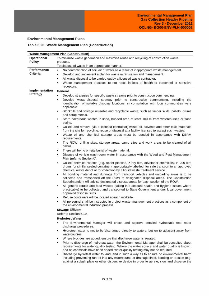
Environmental Management Plan Gas Collection Header Pipeline
Rev 3 - December 2011 QCLNG- BG00-ENV-PLN-000002
75 of 89
Environmental Management Plans
Table 6.26: Waste Management Plan (Construction)
Waste Management Plan (Construction) Operational Policy
To minimise waste generation and maximise reuse and recycling of construction waste products. To dispose of waste in an appropriate manner.
Performance Criteria
• No contamination of soil, air or water as a result of inappropriate waste management. • Develop and implement a plan for waste minimisation and management. • All waste disposal to be carried out by a licensed waste contractor. • Waste management practices to not result in loss of health to personnel or sensitive
receptors. Implementation Strategy
General • Develop strategies for specific waste streams prior to construction commencing. • Develop waste-disposal strategy prior to construction commencing, including the
identification of suitable disposal locations, in consultation with local communities were applicable.
• Stockpile and salvage reusable and recyclable waste, such as timber skids, pallets, drums and scrap metals.
• Store hazardous wastes in lined, bunded area at least 100 m from watercourses or flood plains.
• Collect and remove (via a licensed contractor) waste oil, solvents and other toxic materials from the site for recycling, reuse or disposal at a facility licensed to accept such wastes.
• Waste oil and chemical storage areas must be bunded in accordance with DERM requirements.
• The ROW, drilling sites, storage areas, camp sites and work areas to be cleared of all debris.
• There will be no on-site burial of waste material. • Dispose of vehicle wash-down water in accordance with the Weed and Pest Management
Plan (refer to Section 0). • Collect chemical wastes (e.g. spent pipeline, X-ray film, developer chemicals) in 200 litre
drums (or similar sealed container), appropriately labelled, for safe transport to an approved chemical waste depot or for collection by a liquid waste treatment service.
• All bonding material and dunnage from transport vehicles and unloading areas is to be collected and transported off the ROW to designated disposal areas. The Construction Superintendent will advise designated disposal areas for each section of the ROW.
• All general refuse and food wastes (taking into account health and hygiene issues where practicable) to be collected and transported to State Government and/or local government approved disposal sites.
• Refuse containers will be located at each worksite. • All personnel shall be instructed in project waste- management practices as a component of
the environmental induction process.
Sewage Effluent Refer to Section 6.19.
Hydrotest Water • The Environmental Manager will check and approve detailed hydrostatic test water
discharge procedures. • Hydrotest water is not to be discharged directly to waters, but on to adjacent away from
watercourses. • Where biocides are added, ensure that discharge water is aerated. • Prior to discharge of hydrotest water, the Environmental Manager shall be consulted about
requirements for water-quality testing. Where the water source and water quality is known, and no chemicals have been added, water-quality testing may not be required.
• Discharge hydrotest water to land, and in such a way as to ensure no environmental harm including preventing run-off into any watercourse or drainage lines, flooding or erosion (e.g. against a splash plate or other dispersive device in order to aerate, slow and disperse the

Environmental Management Plan Gas Collection Header Pipeline
Rev 3 - December 2011 QCLNG- BG00-ENV-PLN-000002
76 of 89
Waste Management Plan (Construction) flow).
• All solid waste (e.g. mill scale, construction debris) is to be captured and disposed of through the waste management system.
• Discharge of hydrotest water shall be in compliance with all regulatory and landholder requirements and shall not cause environmental harm.
• The treatment and disposal of hydrotest water containing biocides shall be done in accordance with the recommendations made in the CSIRO Manufacturing and Infrastructure Technology report (2005).
Monitoring and Auditing
• During construction, the entire length of the ROW and associated access areas will be regularly inspected to assess the effectiveness of Waste Management Practices.
• Housekeeping checks will ensure waste is being stored correctly and there is no littering. • Regular audits of this EMP will be undertaken, and recommendations and corrective actions
shall be implemented. • Review of old campsite area after relocation. • Review of waste-management procedures, and quantity of regulated wastes generated.
Reporting and Corrective Action
• Non-Compliance and Incident Reporting will be reported to, and regulated by, senior management to ensure prompt rectification and change management as required.
• Landholder complaints will be recorded and appropriately acted upon by the Environmental Manager (refer to Section 6.22)
Table 6.27: Waste Management Plan
Waste Management Plan (Operation) Management Policy
To minimise waste generation and maximise reuse and recycling of construction waste products. To dispose of waste in an appropriate manner.
Performance Objectives
• No contamination of soil, air or water as a result of inappropriate waste management. • Develop and implement a plan for waste minimisation and management. • All waste disposal to be carried out by a licensed waste contractor. • Waste management practices to not result in loss of health to personnel or sensitive
receptors. Implementation Strategy
• Locate refuse containers at above-ground facilities. • Where practical, segregated and reuse/recycle wastes (e.g. scrap metal). • Dispose of all litter and general waste at a local municipal waste station using an approved
waste contractor. • Instruct all personnel in waste-management practices as a component of the induction
process. • Transport and dispose of all hazardous wastes (i.e. DERM Regulated Wastes, such as oils,
semi-fluid lubricants and ethylene glycol) by a licensed contractor to an approved facility. • Waste fuels, oils and chemicals will be contained within on-site systems and stored in
accordance with relevant Australian Standards (including AS 1940) and Fire Safety regulations.
• Store and handle all oils and chemical wastes (bunding as per regulatory guidelines) in accordance with the relevant Australian Standards and Fire Safety regulations.
• Maintain records of all regulated wastes stored (and removed) from site. • Provide safety and response training for all personnel. • Provide and maintain materials and equipment for responding to hazardous spill incidents.
Monitoring and Auditing
• Six-monthly operations inspections and regular ROW patrols and surveys. • Waste spill observations to be included in reports from pipeline and facility inspections,
ground patrols and any operational audit undertaken. • The Proponent and/or contractor(s) to retrieve and dispose of worksite waste within
24 hours of notification. Reporting and Corrective Action
• Report hazardous waste spills to the Environmental Manager. • Water quality analysis of the wastewater discharge to the evaporation pond on an annual
basis in accordance with the EA.

Environmental Management Plan Gas Collection Header Pipeline
Rev 3 - December 2011 QCLNG- BG00-ENV-PLN-000002
77 of 89
6.19 Effluent Disposal
Environmental Values
The ROW for the Gas Collection Header traverses a variety of different environments ranging from remnant vegetation patches through to cleared agricultural land. These environmental values are to be protected through the careful location of effluent and sewage sludge producing activities and selection of treatment and release methods.
Any effluent from temporary, mobile toilets along construction right of ways will either be:
• managed by the relevant contractor and disposed of at an appropriately licensed waste disposal facility or
• transferred to effluent treatment facilities at camps.
Potential Impacts On Environmental Values
Potential environmental impacts on environmental values for the release of effluent can include:
• Eutrophication of waters due increased nutrient and organic matter;
• Impacts associated with the accumulation of toxicants such as heavy metals;
• Impacts on downstream aquatic communities;
• Soil contamination; and
• Public health and safety impacts.
Effluent Disposal Management Plans
Table 6.28: Effluent Disposal Management Plan (Construction)
Effluent Disposal Management Plan (Construction) Policy To release treated effluent and manage sewage sludge without causing environmental harm. Performance Criteria
• Treated effluent meets quality requirements of design parameters. • All sewage sludge is disposed off at an appropriate sewerage disposal facility.
Implementation Strategy
• Sewage treatment plants will be subject to a site- based management plan, also detailing the irrigation of treated effluent.
• All regulated waste must be recorded and tracked in accordance with the EP regulations, which includes keeping records of the pickup date, waste description, quantity, origin and destination.
• Sewage will be treated to Class A Effluent standard • Raw sewage will be gravity-fed into a pump well and balance tank(s) and will then flow
through treatment units composed of a number of components including: − a primary tank which undertakes sedimentation, digestion and storage of solid matter − balance tank for flow equalisation − aeration tank to reduce organic matter − clarifier for further removal of residual suspended solids − final effluent tank for disinfection and storage of treated water − filter feed tank, gravity-fed from the final effluent tank − ultra filtration membrane − chlorine dosing − final treated effluent tank with three days wet-weather storage.
• Sanitary bio-solids or sludge from camp sewage treatment operations will be disposed at commercially licensed offsite facilities as necessary.
• Sludge from the onsite wastewater treatment facilities will be pumped out periodically and

Environmental Management Plan Gas Collection Header Pipeline
Rev 3 - December 2011 QCLNG- BG00-ENV-PLN-000002
78 of 89
Effluent Disposal Management Plan (Construction) transported to the nearest licensed wastewater treatment works.
• The effluent disposal system will consist of a fenced (sediment fencing and bund). • The final treatment method will be selected in consultation with the relevant Council and
DERM. Monitoring And Auditing
• Significant sewage treatment plants with irrigation mechanisms will be tested every six months and be subject to daily, weekly and monthly checks.
• Daily treated effluent discharge limits to be reviewed monthly. • The annual audit will encompass effluent waste tracking. • The waste transfer station will record all wastes that it manages on-site. • Soil and water quality in and around irrigation areas will be tested on a regular basis. • The quality of treated effluent discharged to land will be monitored in accordance with the
Project derived quality requirements. Reporting And Corrective Action
• The waste transfer station will use an on-site EHS and EMS program to manage all wastes. • Any non-compliance with sewage management plans will be followed up and corrective
actions taken • Irrigation regimes will be amended depending on the results of soils and water quality
monitoring.
During Pipeline operations there will not be any camps requiring management of effluent.
6.20 Rehabilitation
Environmental Values
Rehabilitation of disturbed areas will be undertaken to reinstate the area to the state of the surrounding environment and pre-disturbance land use, both immediately and gradually as the particular areas require. The ROW of the Gas Collection Header will be partially reinstated immediately upon completion of construction. These works will be carried out in accordance with the Australian Pipeline Industry Associate (APIA) Code. To ensure appropriate revegetation techniques for the differing land types along the ROW, rehabilitation plans will be developed and implemented which are tailored to specific vegetation communities or land classifications such as State Forest areas. Rehabilitation activities are likely to include:
• Retain and store topsoil to ensure it can be re-instated and the seed bank remains viable to support natural regeneration;
• Re-profiling natural contours and drainage lines to their original profile to the greatest extent practicable with topsoil spread across the ROW to minimise erosion and promote vegetation regrowth;
• Re-spreading mulch or felled vegetation across the ROW for stability and/or fauna habitat and to support the natural regeneration process;
• Installation of permanent erosion and sediment controls to shed runoff from the altered surface;
• Restoration of watercourses by installing, as required, jute matting on the banks, contour berms on the high bank, rock lining the creek base to minimise scour, and limiting the use of fertilizers;
• Direct seeding with a standard QGC mix approved by the landholder.
Table 6.29: Revegetation and Rehabilitation Management Plan
Revegetation and Rehabilitation Management Plan Operational To restore, as far as reasonably practicable, land to its pre-construction land form and vegetation

Environmental Management Plan Gas Collection Header Pipeline
Rev 3 - December 2011 QCLNG- BG00-ENV-PLN-000002
79 of 89
Revegetation and Rehabilitation Management Plan Polic y cover. Performance Criteria
• All significantly disturbed land is rehabilitated so that the distribution of vegetation communities represent that of adjacent areas and the pre-disturbed distribution.
• Analogue sites to be established for comparative monitoring are to represent the land use(s), topographic and soil characteristics and vegetation community(ies) of each area to be rehabilitated prior to rehabilitation commencing.
• Natural regeneration of native vegetation will be allowed to occur except within those areas required for ongoing maintenance and over the top of the buried pipeline. Large trees will not be permitted to grow within 5m either side of the pipeline.
• The re-establishment of native vegetation will include the shrubby understorey and ground cover, providing habitat for small ground dwelling fauna species and restoration of landscape connectivity.
• Site specific rehabilitation plans are to be prepared by the construction contractor in relation to all areas of remnant vegetation and mapped areas of MNES prior to commencement of rehabilitation in these areas. These plans will contain further detail on the regional ecosystem, species composition and habitat values present prior to clearing, document and map the location of the area, how rehabilitation will be conducted and performance criteria. The following rehabilitation performance criteria will be used as a guide when preparing such plans: i. The rehabilitated site shows distinct and progressive re-establishment of the various
strata which characterises the pre-disturbed vegetation communities;
ii. All dominant species within each strata are re-established at densities and frequencies equivalent to that of the pre-disturbed site;
iii. Habitat structures, including (but not limited to) litter cover, fallen woody material, hollow logs, etc. should be re-established to reflect the pre-disturbed values;
iv. Suitable analogue sites are to be used for measuring rehabilitation success that represent the land use(s), topographic and soil characteristics and vegetation community(ies) of each area to be rehabilitated.
• Within two years from completion of pipeline construction the rehabilitation will result in self-sustaining vegetation cover with a species diversity similar to that of surrounding undisturbed areas and the pre-clearing vegetation.
• No weed species introduced. • Rehabilitation area stabilised with appropriate sediment and erosion control measures with
no significant erosion events until vegetation is self-sustaining or at least the first twelve months.
Implementation Strategy
Prior to clearing, the native vegetation which is present will be surveyed as part of pre-clearance surveys to document such features as the regional ecosystem, species composition and condition.
• Analogue sites will be established prior to rehabilitation commencing to establish benchmarks for rehabilitation, compare against the rehabilitation progress and verify compliance with performance objectives.
• Topsoil will be appropriately separated and stockpiled and reinstated within one month of completion of all construction activities in that area. For watercourses which drain an existing and named river, creek or tributary (not ephemeral) reinstatement will occur prior to the end of the shift if not immediately post backfill to ensure impacts are minimised.
• Re-profiling natural contours and drainage lines to their original profile to the greatest extent practicable taking into account landscape features and variation.
Pipeline Weed Management Plan to be implemented and no weed species introduced.
• Rehabilitation area stabilised with no significant erosion events. • Respread felled native vegetation and timber over the ROW (but maintaining operational
access to the buried pipe) to assist natural regeneration and provide habitat for ground-dwelling fauna.
• Site specific rehabilitation plans will be prepared by the construction contractor prior to rehabilitation commencing. These will address as a minimum areas of remnant vegetation and confirmed MNES ecological communities and species habitats. These site specific

Environmental Management Plan Gas Collection Header Pipeline
Rev 3 - December 2011 QCLNG- BG00-ENV-PLN-000002
80 of 89
Revegetation and Rehabilitation Management Plan rehabilitation plans will include further detail regarding specific rehabilitation measures and performance criteria.
• Compacted ground is to be treated appropriately to remove any impediment to revegetation, however in the case of Brigalow rehabilitation, ground disturbance is to be minimised to encourage suckering.
• No burning of felled vegetation or deliberate lighting of fires. Felled vegetation should be redistributed to provide fauna habitat and to assist in revegetation and erosion control. This will further encourage regrowth within these communities, as well as minimise weed infestations.
• Vegetation shall not be pushed into gullies, waterways or other drainage lines.
• When re-spreading on slopes, tree trunks should be along the line of the contour. The root ball for large trees should be left lying to the outer edge of the ROW.
• Felled vegetation should be re-spread in “filter strips” NOT distributed across the entire ROW so that access is prevented during operations and any erosion or subsidence will be apparent during subsequent monitoring inspections.
• Revegetation should occur naturally and in line with pre-disturbance vegetation communities and surrounding vegetation. Restoration activities will comply with the Pipeline EA and Construction Environment Management Plan (CEMP).
• Areas where natural regeneration has not occurred and/or plant growth is not advancing after twelve months, an investigation will be undertaken to determine issues (such as topsoil inversion) and rectification carried out. This may include direct seeding with native species of local provenance (or with existing dominant surrounding pasture species where the previous land use was grazing land). Use of tube stock or other more intensive measures will be considered in areas where SSMPs recommend greater intervention.
• Any re-seeding plan implemented will be based on soil type and existing local ground layer vegetation characteristics (i.e. native or improved pastures) along the route. The type of species to be used, density of plantings etc will be determined as part of the development of the site specific rehabilitation plans.
• No areas will be left in an unstable condition. • No unplanned change in drainage patterns will occur to avoid increased soil erosion. • Drainage patterns will be reinstated correctly. • Re-spread and compact subsoil over the trench, with crown development, and use subsoil for
the construction of contour banks on steep slopes and above banks at water crossings. • The ROW, all work areas, temporary access tracks and other areas that have been
compacted by construction activities to be ripped or scarified to relieve compaction and to trap water and seed. Particular attention will be paid to areas subject to regular watering and high traffic.
• Compaction relief to be carried out along the contours (parallel) to minimise rilling. • Drainage lines to be restored as appropriate. • Any wheel ruts to be graded and erosion-control measures installed. • Temporary access roads not required for operations or to be retained by the landowner to be
closed and reinstated to a condition compatible with the surrounding land use. • Where access routes are to be retained, but are not public
(i.e. existing tracks), the entry to be blocked and disguised (e.g. by dog-legging or felled vegetation spreading).
• Access tracks in existence prior to construction are not to be blocked in anyway. • New access tracks to be retained at the request of the landowner must be documented by
agreement and confirmed with the Environmental Manager before departure. • Flagging used to identify clearing boundaries and sensitive features to be removed. • Permanent erosion and sediment control measures are to be installed where necessary.
Existing soil-erosion measures will be reinstated to a condition at least equal to the pre-existing state (refer also to Section 6.10).
• Above-ground infrastructure (e.g. valves and pigging stations) to be fenced to discourage third-party, stock and wildlife entry.

Environmental Management Plan Gas Collection Header Pipeline
Rev 3 - December 2011 QCLNG- BG00-ENV-PLN-000002
81 of 89
Revegetation and Rehabilitation Management Plan • Permanent pipeline warning signs to be erected along the ROW in accordance with AS2885. • All waste materials and equipment to be removed from the pipeline construction area once
backfilling and tie-ins are completed (refer to Section 6.18). • Where revegetation of the ROW has not commenced by the end of construction, stabilisation
of areas at risk of erosion (e.g. watercourse banks and approaches) will be carried out (e.g. placement of rock, timber or jute matting) as instructed by the Environmental Manager – Constructor and/or person suitably qualified in soil-erosion controls.
• Use quick-growing and (preferably) native species and/or those that are compatible with the adjacent grazing uses to provide cover in highly erodible areas.
• If in the unlikely event imported topsoil (of an appropriate quality and weed free) is required for construction-corridor repairs, this will only be used with landholder approval.
Monitoring and Auditing
• Analogue sites to be established for comparative monitoring are to represent the land use(s), topographic and soil characteristics and vegetation community(ies) of each area to be rehabilitated prior to rehabilitation commencing.
• Parameters to be measured in the analogue site for comparison against rehabilitated sites to determine rehabilitation success include as a minimum:
• Flora species richness and diversity;
• A description of the structural strata present;
• Dominant species within each strata;
• Associated stem count densities;
• Percentage foliage cover.
• Regular weekly inspections following reinstatement works will be undertaken to evaluate weeds, stability and rehabilitation success until the site is considered stable. Inspections will then be relaxed to monthly inspections to assess for ongoing success.
• After the initial twelve months, monitoring will be undertaken quarterly for the next twelve months at which time the vegetation should be self-sustaining and not require significant weed control or maintenance input.
• Monitoring will then occur annually until the rehabilitation has met the performance objectives
as detailed in the site specific rehabilitation plans. Guiding principles are outlined above. • Monitoring will also include an assessment of the effectiveness of weed-control measures. • The process of monitoring and rehabilitation will conclude only once the site becomes stable
and rehabilitation achieves the performance objectives. • Regular audits of this EMP will be undertaken, and recommendations and corrective actions
implemented. Reporting and Corrective Action
• Non-Compliance and Incident Reporting will be reported to, and regulated by, senior management to ensure prompt rectification and change management as required.
• Landholder complaints will be recorded and appropriately acted upon by the Environmental Manager (see Section 6.22)
• Areas where natural regeneration has not been successful after twelve months, an investigation will be undertaken to determine issues (such as topsoil inversion) and rectification carried out. This may include direct seeding with native species of local provenance (or with existing dominant surrounding pasture species where the previous land use was grazing land). Use of tube stock or other more intensive measures will be considered in areas where SSMPs recommend greater intervention.
Revegetation and rehabilitation will take place following construction of the Pipelines. Any further disturbance during operations will be managed in accordance with the Revegetation and Rehabilitation Plan.
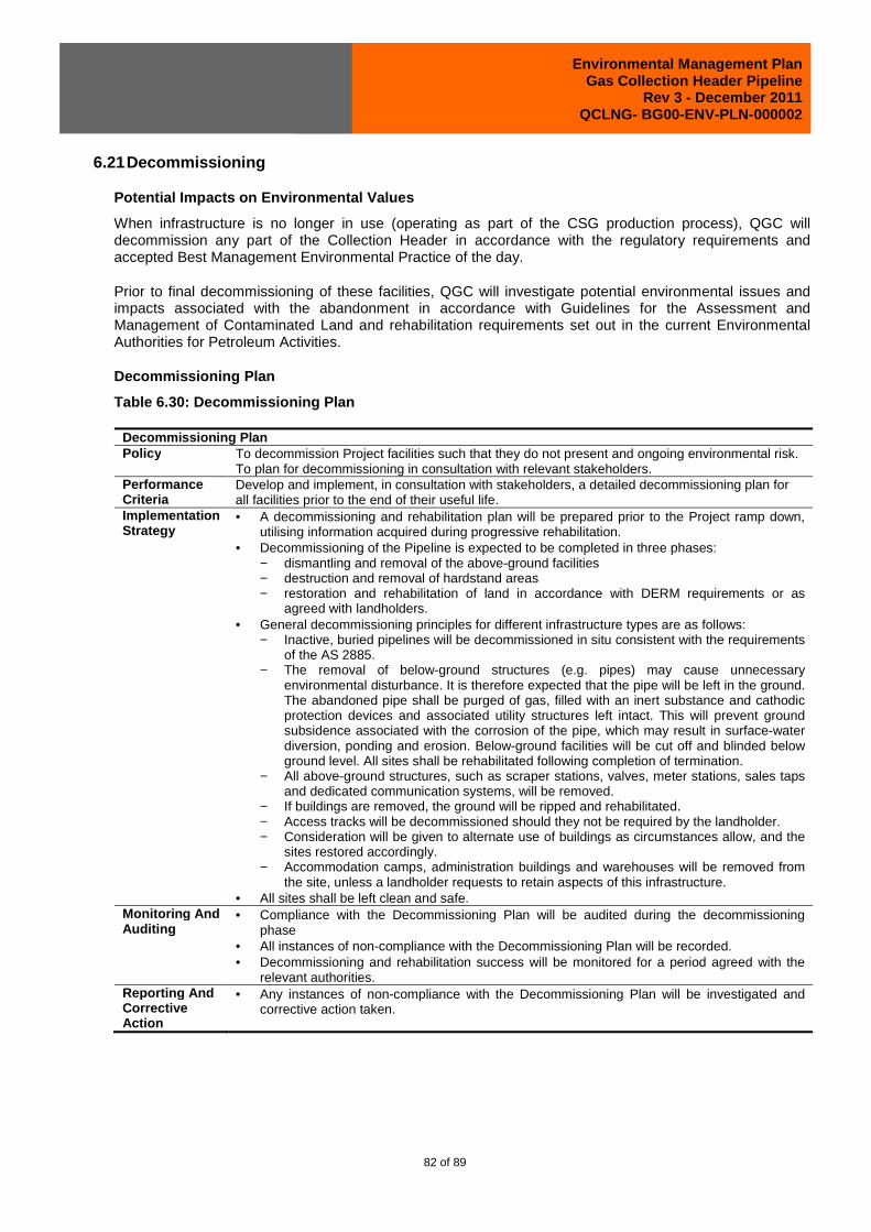
Environmental Management Plan Gas Collection Header Pipeline
Rev 3 - December 2011 QCLNG- BG00-ENV-PLN-000002
82 of 89
6.21 Decommissioning
Potential Impacts on Environmental Values
When infrastructure is no longer in use (operating as part of the CSG production process), QGC will decommission any part of the Collection Header in accordance with the regulatory requirements and accepted Best Management Environmental Practice of the day.
Prior to final decommissioning of these facilities, QGC will investigate potential environmental issues and impacts associated with the abandonment in accordance with Guidelines for the Assessment and Management of Contaminated Land and rehabilitation requirements set out in the current Environmental Authorities for Petroleum Activities.
Decommissioning Plan
Table 6.30: Decommissioning Plan
Decommissioning Plan Policy To decommission Project facilities such that they do not present and ongoing environmental risk.
To plan for decommissioning in consultation with relevant stakeholders. Performance Criteria
Develop and implement, in consultation with stakeholders, a detailed decommissioning plan for all facilities prior to the end of their useful life.
Implementation Strategy
• A decommissioning and rehabilitation plan will be prepared prior to the Project ramp down, utilising information acquired during progressive rehabilitation.
• Decommissioning of the Pipeline is expected to be completed in three phases: − dismantling and removal of the above-ground facilities − destruction and removal of hardstand areas − restoration and rehabilitation of land in accordance with DERM requirements or as
agreed with landholders. • General decommissioning principles for different infrastructure types are as follows:
− Inactive, buried pipelines will be decommissioned in situ consistent with the requirements of the AS 2885.
− The removal of below-ground structures (e.g. pipes) may cause unnecessary environmental disturbance. It is therefore expected that the pipe will be left in the ground. The abandoned pipe shall be purged of gas, filled with an inert substance and cathodic protection devices and associated utility structures left intact. This will prevent ground subsidence associated with the corrosion of the pipe, which may result in surface-water diversion, ponding and erosion. Below-ground facilities will be cut off and blinded below ground level. All sites shall be rehabilitated following completion of termination.
− All above-ground structures, such as scraper stations, valves, meter stations, sales taps and dedicated communication systems, will be removed.
− If buildings are removed, the ground will be ripped and rehabilitated. − Access tracks will be decommissioned should they not be required by the landholder. − Consideration will be given to alternate use of buildings as circumstances allow, and the
sites restored accordingly. − Accommodation camps, administration buildings and warehouses will be removed from
the site, unless a landholder requests to retain aspects of this infrastructure. • All sites shall be left clean and safe.
Monitoring And Auditing
• Compliance with the Decommissioning Plan will be audited during the decommissioning phase
• All instances of non-compliance with the Decommissioning Plan will be recorded. • Decommissioning and rehabilitation success will be monitored for a period agreed with the
relevant authorities. Reporting And Corrective Action
• Any instances of non-compliance with the Decommissioning Plan will be investigated and corrective action taken.

Environmental Management Plan Gas Collection Header Pipeline
Rev 3 - December 2011 QCLNG- BG00-ENV-PLN-000002
83 of 89
6.22 Incidents And Complaints
An environmental incident will be regarded as any incident that harms or has the potential to harm environmental and social values. In the event that an environmental incident occurs, the following steps will be followed immediately:
• Prevention of further pollution/environmental harm (including impacts on air, water quality, flora and fauna and noise environment)
• Clean-up and/or control of polluting substance(s)
• Implementation of mitigation measures to prevent recurrence of similar incident
• Reporting and documenting of incident and instigation of incident
• Investigation in accordance with BG Group Standards.
All environmental incidents, near-misses and hazards will be reported via the Synergi incident reporting system in accordance with the BG Group Standard for incident reporting. Complaints will be handled by the Land Access and Communications teams in the first instance, who will liaise with the complainant(s), the Environment Team and the Environment Manager for an effective resolution. The Environment Manager has responsibility to ensure that all complaints are addressed and appropriately closed off.
The Incident and Complaint Management Plan is set out in Table. As management and response to incidents and complaints will remain consistent throughout the life of the project, this management plan is considered appropriate for both construction activities and operations.
Incident and Complaint Management Plan
Table 6.31: Incidents and Complaints Management Plan
Incidents and Complaints Management Plan Operational Policy
To have a process whereby all complaints can be lodged and responded to in an appropriate manner.
Performance Criteria
• Record all complaints and responses in an incidents and complaints register. • Respond appropriately to all incidents and complaints.
Implementation Strategy
• All environmental incidents will be recorded in the Synergi database, with corrective actions assigned and followed up by the responsible person for a particular incident.
• The complaints form will document at least the following information: − Time, date and nature of complaint. − Type of communication (telephone, letter, email, visit). − Name, contact address and contact number (if provided). − Response and investigation undertaken as a result of the complaint. − Action taken and signature of person investigating complaint.
• Each complaint will be investigated as soon as practicable and, where appropriate, action taken to remedy the cause of the complaint. If DERM advises alleged nuisance, it will be investigated and DERM advised of any action proposed or undertaken, and records will be kept of all complaints.
Monitoring and Auditing
• The Environmental Officer will maintain the complaints register and ensure all complaints are resolved. The complaint form will be checked by the Environmental Officer within two weeks of complaint receipt to ensure follow-up action has been taken to resolve the issue.
• Where required, the relevant authorities will be informed of complaints. Reporting and Corrective Action
• All complaints and incidents are to be reported to the Environmental Officer, who will report to the relevant Manager.
• Should further incidents occur or complaints be received in relation to previous occurrences, an appropriate selection of the following corrective actions will be undertaken: − Additional environmental awareness training of the workforce with respect to the
procedures to be followed for environmental incidents or complaints.

Environmental Management Plan Gas Collection Header Pipeline
Rev 3 - December 2011 QCLNG- BG00-ENV-PLN-000002
84 of 89
Incidents and Complaints Management Plan − Investigation into why the incident/complaint was not addressed within the specified
timeframe. − Incident/complaint follow-up according to the results of the investigation. − Where required, work place practices will be reviewed.

Environmental Management Plan Gas Collection Header Pipeline
Rev 3 - December 2011 QCLNG- BG00-ENV-PLN-000002
85 of 89
6.23 Environmental Induction And Training
Impacts to the environmental values from pipeline activities have the potential to occur during both the construction and operation components of the project. All relevant personnel with management and operational responsibilities for the Project will receive training and an induction to ensure they are familiar with the relevant management systems and requirements, as appropriate to their roles and responsibilities. The purpose of the training is to ensure all individuals are aware of their environmental responsibilities and have obtained the skills and competence to fulfil such responsibilities.
The Environmental Induction and Training Plan is set out in Table 6.31. As personnel numbers and on-site activities will be significantly less during the operational phase of the project, this plan is considered appropriate for both construction activities and operations.
Environmental Induction and Training Plan
Table 6.32: Environmental Induction and Training Plan
Environmental Induction and Training Plan Operational Policy
To ensure that all Project personnel, including contractors, comply with the environmental requirements of all tasks.
Performance Criteria
• All personnel undergo site inductions and, where necessary, additional training, that address environmental requirements of Project activities.
• Full compliance with induction and training procedures. Implementation Strategy
• Training programs will be conducted as required. • All site staff to be made aware of the Project EMP, EA conditions, environmentally sensitive
areas and environmental responsibilities. • Identify the skills required to effectively implement the Project; and the EMP and its
procedures or sub plans. Ensure the skills of relevant contractors working on the site are also included.
• As a minimum, everyone will have basic environmental training and be familiar with the EMP, their roles and responsibilities detailed in it and what it requires in their job.
• Develop an induction training plan that explains environmental obligations, the purpose of the EMP and any issues new starters, whether permanent or contractors, must be aware of.
• Identify and describe how specific operations’ skills training will occur, when and with which staff. Ensure all site staff are aware of their responsibilities in implementing work instructions or procedures contained in the EMP.
• Ensure a document exists that clearly lists who will require training, the frequency of training and the procedure to document training activities. Identify to what basic level or standard training will be targeted.
Monitoring and Auditing
• The success of the training programs will be assessed and documented. • Non-compliance with training will be recorded
Reporting and Corrective Action
• In the event of a staff member not being adequately trained or inducted, training activities will be undertaken as necessary.
• The training or induction programme will be revised accordingly.
6.24 Emergency Response For Environmental Incidents
Impacts to the environmental values from pipeline activities have the potential to occur during both the construction and operation components of the project. Appropriate emergency response needs to be in place for the life of the project. The Emergency Response for Environmental Incidents Management Plan is set out in Table 6.33.

Environmental Management Plan Gas Collection Header Pipeline
Rev 3 - December 2011 QCLNG- BG00-ENV-PLN-000002
86 of 89
Emergency Response for Environmental Incidents Mana gement Plan
Table 6.33: Emergency Response for Environmental Incidents Management Plan
Emergency Response for Environmental Incidents Manage ment Plan Policy To ensure that Project personnel can respond effectively and efficiently in the event of an
environmental incident to ensure no long-term adverse impacts on health, safety or the environment.
Performance Criteria
• Any emergency response addressed in accordance with the QGC Emergency Management Plan.
• Nil government notices. Implementation Strategy
• A detailed Crisis and Emergency Management Plan will be prepared and will include the following: − Response procedures in the event of a fire, chemical release, spill, leak, explosion,
equipment failure, bomb threat, natural disaster (including severe storm and flood events) or any other likely emergency.
− Communication arrangements and contact details. − Roles and responsibilities of relevant personnel. − Emergency controls and alarms. − Evacuation procedures. − Emergency response equipment. − Leak detection and control points. − Training requirements. − Site access and security. − Notify and report to DERM. − Develop callout response plan. − Spill-containment procedure. − Safely recover spillage. − Clean-up and rehabilitation. − Incident investigation. − ER training (refer Section 6.31 Error! Reference source not found.). − Monitoring and detection systems. − Callout contact lists. − Measures to halt spill [i.e. control pumps, etc. − Personnel responsibilities. − Equipment requirements. − Location, storage, maintenance and transport of equipment to site. − Communications and logistics.
Monitoring And Auditing
• The effectiveness of the emergency response plan will be tested at least annually and audited.
Reporting And Corrective Action
• The Corporate HSSE Manager will be responsible for compiling the results of testing and auditing programs. These results will be reported to the relevant Manager.
• The following constitute incidents or failure to comply: 1. Emergency response plan is not prepared or implemented. 2. Emergency response equipment is not provided. 3. Emergency response training is not undertaken. 4. Emergency response procedures not followed in the event of an incident.
• In the event of an incident or failure to comply, a selection of the following actions will be undertaken, as appropriate: 1. Prepare or implement the emergency response plan. 2. Provide the necessary equipment or training. 3. Investigate why the emergency response procedures were not followed and implement
mitigating measures.

Environmental Management Plan Gas Collection Header Pipeline
Rev 3 - December 2011 QCLNG- BG00-ENV-PLN-000002
87 of 89
7.0 STAKEHOLDER FEEDBACK PROCEDURES
QGC has prepared Stakeholder Feedback Procedures which describes the process for making a complaint or grievance as well as receiving, handling, monitoring and tracking complaints or grievances regarding any actions or activities undertaken by QGC.
The stakeholder feedback mechanisms include:
• A free call 1800 number where communities can lodge complaints or concerns 24 hours a day, 7 days per week
• Stakeholder email address: [email protected] and [email protected]
• Direct contract with QGC employees
• Feedback forms
• External third parties
• The Grievance Procedure stipulates:
• Timeframes for QGC to respond to complaints
• Investigation roles and responsibilities for investigating, auctioning and reporting
• Tracking of progress
• Appeals process and procedures
• Management review.
QGC’s stakeholder feedback procedure has been developed and is available on the QCLNG website: http://www.qclng.com.au/.
8.0 INSPECTION AND AUDITING PROGRAM
The QCLNG Environment Team will be required to conduct:
• regular inspections (at least quarterly) on those activities being conducted in the area covered by this EM Plan
• an annual audit of the activities being conducted over the year as part of this EM Plan and determine a level of compliance with this EM Plan and the Environmental Authority by QGC and its contractors
• audit all registers such as licensing and permitting, waste, legal, discharges etc to determine the adequacy of the records being kept.
All audit findings are to be reported to the General Managers of the QCLNG Project for:
• Environment
• Project Delivery (Gas Fields, Pipeline and LNG)
• BG Group HSSE.
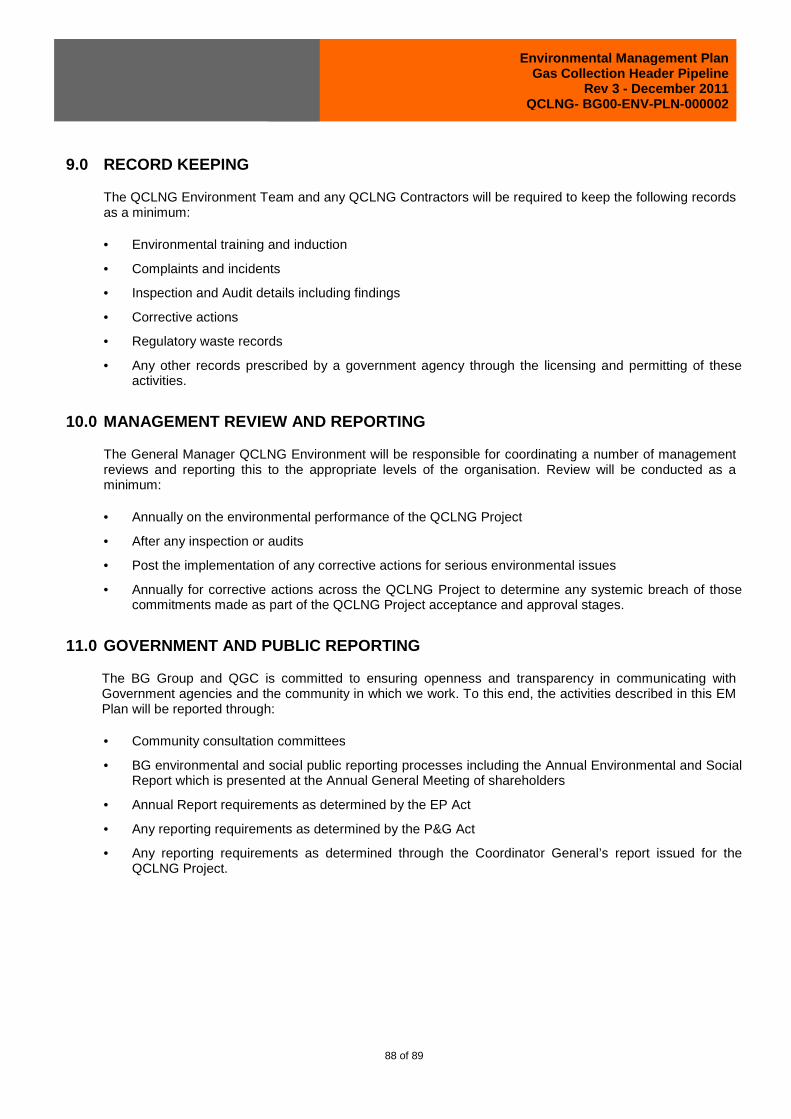
Environmental Management Plan Gas Collection Header Pipeline
Rev 3 - December 2011 QCLNG- BG00-ENV-PLN-000002
88 of 89
9.0 RECORD KEEPING
The QCLNG Environment Team and any QCLNG Contractors will be required to keep the following records as a minimum:
• Environmental training and induction
• Complaints and incidents
• Inspection and Audit details including findings
• Corrective actions
• Regulatory waste records
• Any other records prescribed by a government agency through the licensing and permitting of these activities.
10.0 MANAGEMENT REVIEW AND REPORTING
The General Manager QCLNG Environment will be responsible for coordinating a number of management reviews and reporting this to the appropriate levels of the organisation. Review will be conducted as a minimum:
• Annually on the environmental performance of the QCLNG Project
• After any inspection or audits
• Post the implementation of any corrective actions for serious environmental issues
• Annually for corrective actions across the QCLNG Project to determine any systemic breach of those commitments made as part of the QCLNG Project acceptance and approval stages.
11.0 GOVERNMENT AND PUBLIC REPORTING
The BG Group and QGC is committed to ensuring openness and transparency in communicating with Government agencies and the community in which we work. To this end, the activities described in this EM Plan will be reported through:
• Community consultation committees
• BG environmental and social public reporting processes including the Annual Environmental and Social Report which is presented at the Annual General Meeting of shareholders
• Annual Report requirements as determined by the EP Act
• Any reporting requirements as determined by the P&G Act
• Any reporting requirements as determined through the Coordinator General’s report issued for the QCLNG Project.

Environmental Management Plan Gas Collection Header Pipeline
Rev 3 - December 2011 QCLNG- BG00-ENV-PLN-000002
89 of 89
12.0 CONTINUAL IMPROVEMENT
QGC is working in close collaboration with the EPC Contractors for the Gas Field and Pipeline Components to find ways of minimising those environmental and social impacts identified in this EM Plan.
Through the implementation of the QGC and BG Group plc business principles relating to environment and social performance, QGC will continue to find and implement ways to reduce impacts and deliver positive outcomes through each stage of the Project.
The results of site inspections, audits and incident reports will be used to drive continuous improvement, along with internal environmental performance reviews, conducted as part of the BG Group performance management framework.
Following any justified complaints and corrective actions, this EM Plan will be reviewed to determine if mitigations measures need to be updated or improved.
Following any changes to engineering design, this EM Plan will be reviewed to determine if mitigation measures need to be updated or improved.
Following any environmental incidents resulting in environmental harm, this EM Plan will be reviewed and mitigation measures improved to ensure that the risk of future incidents is minimised.
All major BG operated assets shall operate under a certified Management System to the international standard ISO 14001:2004 within 2 years of acquisition or start up. The adoption of this System will ensure that continual improvement is driven through all aspects of the Project and throughout the life of the QCLNG Project.
This EM Plan will be reviewed annually by the QCLNG Environment Team and its effectiveness in managing the environmental impacts of the pipeline works will be reported internally through the QGC/BG reporting framework and through the annual return process required as part of the Environmental Authority issued for this pipeline works.