전력시스템 해석 및 설계 -...
TRANSCRIPT

전력시스템 해석 및 설계
제 3 장 – Power Transformer -
성균관대학교 김 철 환
CENTER FOR POWER IT

Center for Power IT CENTER FOR POWER IT
전력IT인력양성센터
CONTENTS
3.1 이상 변압기 (THE IDEAL TRANSFORMERS)
3.2 실제 변압기의 등가회로(EQUIVALENT CIRCUIT FOR PRACTICAL TRANSFORMERS)
3.3 단위 법(THE PER-UNIT SYSTEM)
3.4 3상 변압기 결선 및 위상 변위(THREE PHASE TRANSFORMER CONNECTION AND PHASE SHIFT)
3.5 평형 3상 2권선 변압기의 단위 법 등가회로(PER-UNIT EQUIVALENT CIRCUITS OF
BALANCED THREE-PHASE TWO-WINDING TRANSFORMERS)
3.6 3권선 변압기(THREE-WINDING TRANSFORMERS) 3.7 단권 변압기(AUTOTRANSFORMERS) 3.8 비 공칭 권선비를 갖는 변압기(TRANSFORMERS WITH OFF-NORMINAL TURNS
RATIOS)
2/106

Center for Power IT CENTER FOR POWER IT
전력IT인력양성센터
3.6 3권선 변압기
그림 3.20(a) : basic 단상 3권선 변압
기
2권선 변압기의 ideal transformer relations : (3.1.8) , (3.1.14)
이상적인 3권선 변압기의 관계식
In actual units, ,
In per-units,
332211 INININ +=3
3
2
2
1
1
NE
NE
NE
==
..3..2..1 upupup III +=
..3..2..1 upupup EEE ==
3/106

Center for Power IT CENTER FOR POWER IT
전력IT인력양성센터
3.6 THREE-WINDING TRANSFORMERS
누설 임피던스(Per-unit leakage impedances) = 권선 1에서 측정한 per-unit 누설 임피던스(권선 2 단락, 권선 3 개방) = 권선 1에서 측정한 per-unit 누설 임피던스(권선 3 단락, 권선 2 개방) = 권선 2에서 측정한 per-unit 누설 임피던스(권선 3 단락, 권선 1 개방) * 그림 3-20(c) : 권선 2 단락, 권선 3 개방할 때 권선 1에서 측정한
누설 임피던스(병렬 어드미턴스 분기는 무시) 식 (3.6.5) ~ (3.6.7)을 풀면, 직렬 임피던스(Per-unit series impedance)
)7.6.3()5.6.3(,, 322331132112 −+=+=+= ZZZZZZZZZ
12Z
13Z
23Z
)8.6.3()(21
2313121 ZZZZ −+=
)9.6.3()(21
1323122 ZZZZ −+=
)10.6.3()(21
1223133 ZZZZ −+=
4/106

Center for Power IT CENTER FOR POWER IT
전력IT인력양성센터
3.6 THREE-WINDING TRANSFORMERS
EX 3.9) The ratings of a single-phase three-winding transformer are - winding 1: 300 MVA , 13.8 kV - winding 2: 300 MVA , 199.2 kV - winding 3: 50 MVA , 199.2 kV The leakage reactance, from short-circuit tests, are - 0.10 per unit on a 300-MVA , 13.8-kV base - 0.16 per unit on a 50-MVA , 13.8-kV base - 0.14 per unit on a 50-MVA , 199.2-kV base Winding resistances and exciting current are neglected. Calculate the impedances of the per-unit equivalent circuit using a base of 300MVA and 13.8kV for terminal 1.
=12X=13X=23X
5/106

Center for Power IT CENTER FOR POWER IT
전력IT인력양성센터
3.6 THREE-WINDING TRANSFORMERS
Sol) Then, From (3.6.8)-(3.6.10),
unitper 96.050
300)16.0(13 =
=X
unitper 84.050
300)14.0(23 =
=X
( ) unitper 11.084.096.010.021
1 =−+=X
( ) unitper 01.096.084.010.021
2 −=−+=X
( ) unitper 85.010.096.084.021
3 =−+=X
6/106

Center for Power IT CENTER FOR POWER IT
전력IT인력양성센터
3.6 THREE-WINDING TRANSFORMERS
- The per-unit equivalent circuit of this three-winding transformer is show in Figure 3.21. - Note that is negative. This illustrates the fact that , and are not leakage reactance, but instead are equivalent reactances derived from the leakage reactances. Leakage reactances are always positive - Note also that the node where the three equivalent circuit reactances are connected does not correspond to any physical location within the transformer
2X 3X1X 2X
7/106

Center for Power IT CENTER FOR POWER IT
전력IT인력양성센터
3.6 THREE-WINDING TRANSFORMERS
EX 3.10) Three transformers, each identical to that described in Example 3.9, are connected as a three-phase bank in order to feed power from a 900-MVA , 13.8-kV generator to a 345-kV transmission line and to a 34.5-kv distribution line. The transformer windings are connected as follows: - 13.8-kV windings(X) : , go generator - 199.2-kV windings(H) : solidly grounded Y, to 345-kV line - 19.92-kV windings(M) : grounded Y through , to 34.5-kV line The positive-sequence voltages and currents of the high and medium-voltage Y windings lead the corresponding quantities of the low-voltage winding by Draw the per-unit network, using a three-phase base of 900 MVA and 13.8 kV for terminal X . Assumed balanced positive-sequence operation.
∆
Ω= 10.0jZn
∆ .30°
8/106

Center for Power IT CENTER FOR POWER IT
전력IT인력양성센터
3.6 THREE-WINDING TRANSFORMERS
Sol) The per-unit network is shown in Figure 3.22 Since the M and H windings are Y- connected, - which are the rated line-to-line voltages of the M and H windings.
vkVbaseX 8.13=
vkVbaseM 5.34)92.19(3 ==
vkVbaseH 345)2.199(3 ==
9/106
Center for Power IT CENTER FOR POWER IT
전력IT인력양성센터
3.7 단권 변압기
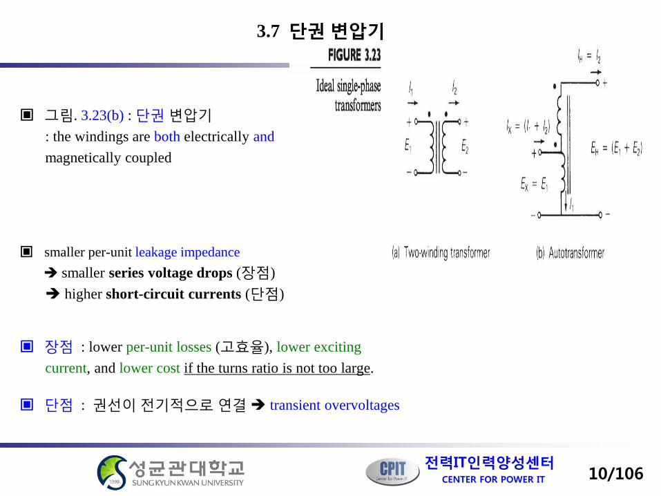
그림. 3.23(b) : 단권 변압기 : the windings are both electrically and magnetically coupled
smaller per-unit leakage impedance smaller series voltage drops (장점) higher short-circuit currents (단점)
장점 : lower per-unit losses (고효율), lower exciting current, and lower cost if the turns ratio is not too large.
단점 : 권선이 전기적으로 연결 transient overvoltages
10/106

Center for Power IT CENTER FOR POWER IT
전력IT인력양성센터
3.7 AUTOTRANSFORMERS
EX 3.11) The single-phase two-winding 20-kVA , 480/120-volt transformer of Example 3.3 is connected as an autotransformer, as in Figure 3.23(b) , where winding 1 is the 120- volt winding. For this transformer, determine a. The voltage ratings and of the low and high-voltage terminals b. The kVA rating c. The per-unit leakage impedance
XE HE
11/106

Center for Power IT CENTER FOR POWER IT
전력IT인력양성센터
3.7 AUTOTRANSFORMERS
Sol)
a. The voltage ratings and of the low and high-voltage terminals b. The kVA rating also,
c. The per-unit leakage impedance
From example 3.3, the leakage impedance is per unit as a normal, two-winding transformer.
XE HE
,120voltsEX = ,1201 voltsEEX == ,4802 voltsE = voltsEEEH 60048012021 ===+=
°∠ 13.780729.0
Ω==Ω== 52.11000,20
)480(,4.14000,25
)600( 22
baseHoldbaseHnew ZZ
unitperZ newup °∠=
°∠= 13.7805832.0
4.1452.11)13.780729.0(..
,667.41480/000,202 AII H === .25)667.41()600( kVAIES HHH ===
AIIIAIAII XH 3.208,7.166)677.41(120480,667.41 2112 =+=====
.25)3.208()120( kVAIES XXX ===
12/106

Center for Power IT CENTER FOR POWER IT
전력IT인력양성센터
변압기의 모델링 : 단위값 사용하는 것이 실제값 사용하는 것보다 간단
회로상에서 이상 변압기 권선의 제거 : 선택된 기준전압의 비 = 권선의 정격전압의 비
일부의 경우, 상기 방법으로 기준전압을 선택하는 것이 불가능 그림 3.24 : 변압기를 병렬로 연결하여 사용할 경우
변압기의 정격전압이 설정된 기준전압에 비례하지 않는 변압기의 단위법 모델 비 공칭 권선비를 갖는 변압기
13/106
3.8 비 공칭 권선비(OFF-NOMINAL TURNS RATIOS)를 갖는 변압기
,/// 212121 NNVVVV ratedratedbasebase ==2
1
2
1
rated
rated
base
base
VV
VV
=

Center for Power IT CENTER FOR POWER IT
전력IT인력양성센터
3.8 TRANSFORMERS WITH OFF-NOMINAL TURNS RATIOS
그림 3.25(a) : 정격전압 , 를 갖는 변압기
설정된 기준전압이 다음을 만족하는 것으로 가정
로 정의하면, 식 (3.8.1)은 다음 식 (3.8.3) 직렬로 연결된 2개의 변압기
(그림 3.25(b) )
2번째 변압기 : 설정된 기준전압 비 b 와 같은 정격의 변압비를 가짐 이 변압기는 그림 3.9 ,3.17과 같은 표준형 단위 모델
ratedV1 ratedV2
ratedtrated VaV 21 =
21 basebase VbV =
bac t /=
ratedratedt
rated VbcVbabV 221 =
=
14/106

Center for Power IT CENTER FOR POWER IT
전력IT인력양성센터
3.8 TRANSFORMERS WITH OFF-NOMINAL TURNS RATIOS
The per-unit model : 그림 3.25(c)
An alternative representation : 그림 3.25(c) 에 마디 방정식 적용
where both and are referenced into their nodes in accordance with the nodal equation method
=
− 2
1
2221
1211
2
1
VV
YYYY
II
1I 2I−
15/106

Center for Power IT CENTER FOR POWER IT
전력IT인력양성센터
3.8 TRANSFORMERS WITH OFF-NOMINAL TURNS RATIOS
식 (3.8.4)의 어드미턴스 값은,
eqeqV
YZV
IY ====
1
01
111
2
eqeqV
YccZV
IY 22
02
222
/1
1
==−
==
eqeq
V
cYV
ZcVVIY −=
−==
= 2
2
02
112
/
1
eqV
YcV
IcVIY *
1
1*
01
221
2
−=−
=−
==
16/106
=
− 2
1
2221
1211
2
1
VV
YYYY
II

Center for Power IT CENTER FOR POWER IT
전력IT인력양성센터
3.8 TRANSFORMERS WITH OFF-NOMINAL TURNS RATIOS
EX 3.12) A three-phase generator step-up transformer is rated 1000 MVA , 13.8 kV / 345 kV Y with The transformer high-voltage winding has taps. The system base quantities are
Determine the per-unit equivalent circuit for the following tap settings:
a. Rated tap
b. -10% tap (providing a 10% voltage decrease for the high-voltage winding)
Assume balanced positive-sequence operation. Neglect transformer winding resistance, exciting current, and phase shift
∆.10.0 unitperjZeq = %10±
MVASbase 5003 =φ
kVVbaseXLL 8.13=
kVVbaseHLL 345=
17/106

Center for Power IT CENTER FOR POWER IT
전력IT인력양성센터
3.8 TRANSFORMERS WITH OFF-NOMINAL TURNS RATIOS
Sol) a. Rated tap
Using (3.8.1) and (3.8.2) with the low- voltage winding denoted winding 1, From (3.3.11) The per-unit equivalent circuit, not including winding resistance, exciting current, and shift is shown in Figure
1345
8.1304.0345
8.13====== ca
VVba t
baseHLL
baseXLLt
unitperjjZ newup 05.01000500)10.0(.. =
=
18/106

Center for Power IT CENTER FOR POWER IT
전력IT인력양성센터
3.8 TRANSFORMERS WITH OFF-NOMINAL TURNS RATIOS
b. -10% tap
Using (3.8.1) and (3.8.2)
From Figure 3.23(d)
The per-unit positive-sequence network is shown in Figure
( ) 04.0345
8.1304444.09.0345
8.13==== bat
unitperjj
cYeq 22.2205.0
11111.1 −=
=
1111.104.0
04444.0===
bac t
( ) unitperjjYc eq 222.220)11111.0()1( =−−=−
( ) unitperjjYcc eq 469.220)1.12346.1()( 2 −=−−=−
19/106

Center for Power IT CENTER FOR POWER IT
전력IT인력양성센터
3.8 TRANSFORMERS WITH OFF-NOMINAL TURNS RATIOS
EX 3.13) Two buses and are connected by two parallel lines L1 and L2 with positive- sequence series reactance and per unit. A regulating transformer is placed in series with line L1 at bus . Determine the bus admittance matrix when the regulating transformer; (a) provide a 0.05 per-unit increase in voltage magnitude toward bus (b) advances the phase toward bus . Assume that the regulating transformer is ideal. Also, the series resistance and shunt admittance of the lines are neglected
cba ′′abc25.01 =LX 20.02 =LX
cba ′′ 22×
cba ′′°3
20/106
Center for Power IT CENTER FOR POWER IT
전력IT인력양성센터
3.8 TRANSFORMERS WITH OFF-NOMINAL TURNS RATIOS
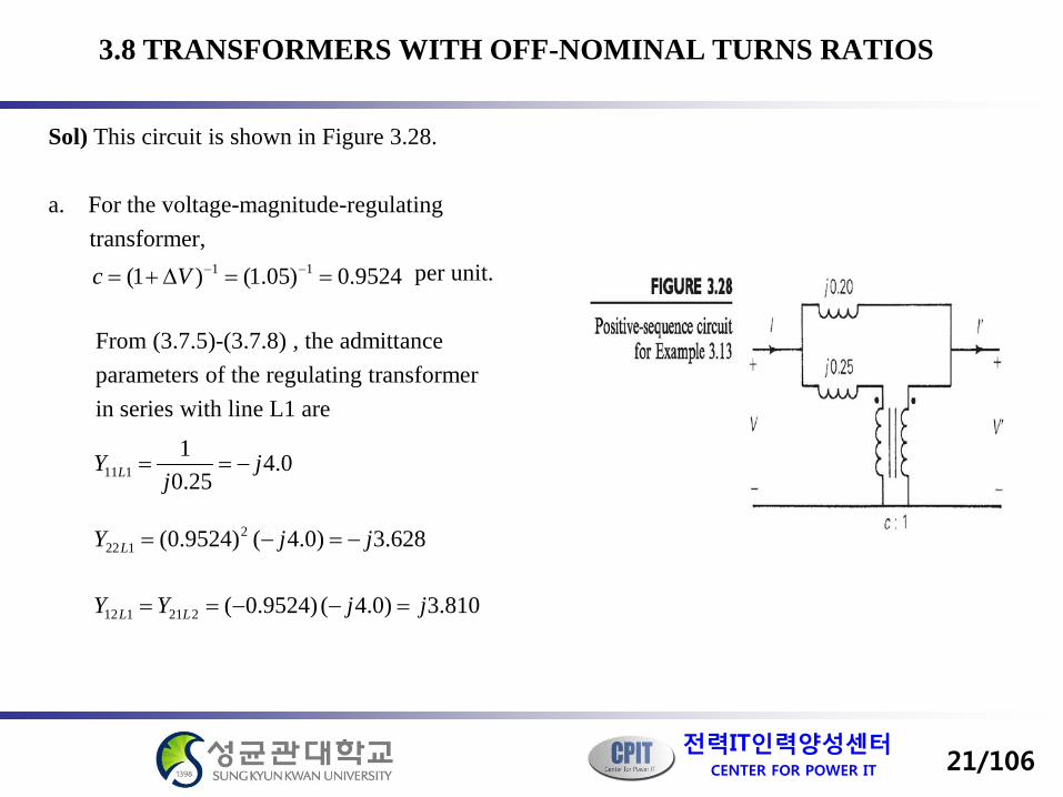
Sol) This circuit is shown in Figure 3.28. a. For the voltage-magnitude-regulating transformer, per unit. From (3.7.5)-(3.7.8) , the admittance parameters of the regulating transformer in series with line L1 are
0.425.0
1111 j
jY L −==
628.3)0.4()9524.0( 2122 jjY L −=−=
810.3)0.4()9524.0(221112 jjYY LL =−−==
9524.0)05.1()1( 11 ==∆+= −−Vc
21/106

Center for Power IT CENTER FOR POWER IT
전력IT인력양성센터
3.8 TRANSFORMERS WITH OFF-NOMINAL TURNS RATIOS
For lone L2 alone, Combining the above admittance in parallel, per unit
0.520.0
1222211 j
jYY LL −===
0.5)0.5(221212 jjYY LL =−−==
0.90.50.421111111 jjjYYY LL −=−−=+=
628.80.5628.322212222 jjjYYY LL −=−−=+=
2121122112 LL YYYY +==
810.80.5810.3 jjj =+=
22/106

Center for Power IT CENTER FOR POWER IT
전력IT인력양성센터
3.8 TRANSFORMERS WITH OFF-NOMINAL TURNS RATIOS
23/106
Center for Power IT CENTER FOR POWER IT
전력IT인력양성센터
3.8 TRANSFORMERS WITH OFF-NOMINAL TURNS RATIOS
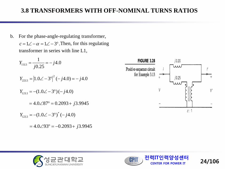
b. For the phase-angle-regulating transformer, Then, for this regulating transformer in series with line L1,
0.425.0
1111 j
jY L −==
0.4)0.4(30.1 2122 jjY L −=−°−∠=
.311 °−∠=−∠= αc
)0.4()30.1(112 jY L −°−∠−=
9945.32093.0870.4 j+=°∠=
)0.4()30.1( *112 jY L −°−∠−=
9945.32093.0930.4 j+−=°∠=
24/106

Center for Power IT CENTER FOR POWER IT
전력IT인력양성센터
3.8 TRANSFORMERS WITH OFF-NOMINAL TURNS RATIOS
The admittance parameters for line L2 alone are given in part (a) above. Combining the admittance in parallel, per unit
0.90.50.42211 jjjYY −=−−==
0.59945.32093.012 jjY ++=
9945.32093.0 j+=
0.59945.32093.021 jjY ++−=
9945.32093.0 j+−=
25/106

Center for Power IT CENTER FOR POWER IT
전력IT인력양성센터
3.8 TRANSFORMERS WITH OFF-NOMINAL TURNS RATIOS
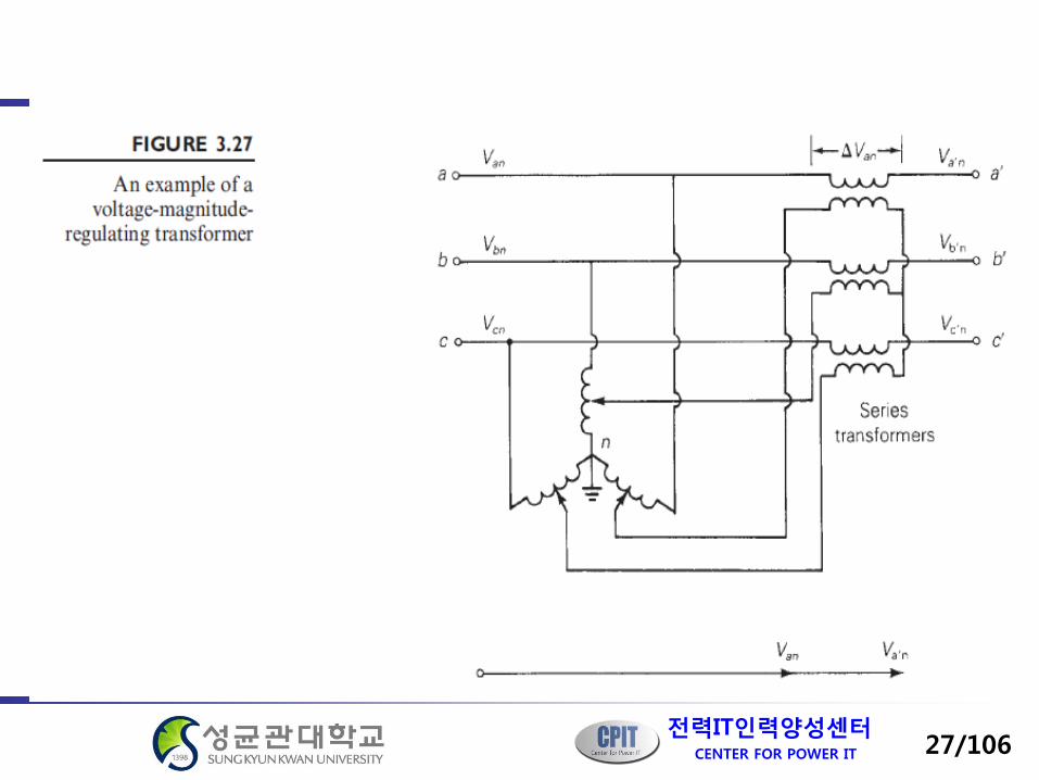
3상 전압조정 변압기
A. 3상 전압 크기 조정 변압기
26/106
Center for Power IT CENTER FOR POWER IT
전력IT인력양성센터
27/106

Center for Power IT CENTER FOR POWER IT
전력IT인력양성센터
3.8 TRANSFORMERS WITH OFF-NOMINAL TURNS RATIOS
B. 3상 전압 위상각 조정 변압기
28/106

Center for Power IT CENTER FOR POWER IT
전력IT인력양성센터
29/106

Center for Power IT CENTER FOR POWER IT
전력IT인력양성센터
30/106

Center for Power IT CENTER FOR POWER IT
전력IT인력양성센터
Questions
[31/32]