equipment and instrumentation - bureau of · pdf filethe purpose of this manual is to assist...
TRANSCRIPT

MA8b Automated Meteorological Observations
and Reports - Equipment and Instrumentation
Requirements

Published by the Bureau of Meteorology 2016 Cover Photo: Sunset over Weather radar at Giles Meteorology Office, WA. – J.Darnley
© Commonwealth of Australia 2016
This work is copyright. Apart from any use as permitted under the Copyright Act 1968, no part may be reproduced without prior written permission from the Bureau of Meteorology. Requests and inquiries concerning reproduction and rights should be addressed to the Production Manager, Communication Section, Bureau of Meteorology, GPO Box 1289, Melbourne 3001. Information regarding requests for reproduction of material from the Bureau website can be found at www.bom.gov.au/other/copyright.shtml

MA8b - Meteorological Observations and Reports Equipment and Instrumentation Requirements
Version.1.0
1
Revision history
Date Version Description Author
14 December 2016 1.0 First version John Darnley
Document management register
Document File reference
MA8b – Equipment and Instrument Requirements – Automatic Weather Stations
60/001248 Publications – Aviation - Meteorological Authority Publications
Review Status
Reviewer Date Reviewed Version Reviewed
Sue O’Rourke (STMA) 30 May 2012 0.11
John Gorman (SRSQ) 14 August 2012 0.3
Keith Mackersy (NZ,CAA) 17 August 2012 0.4
John Gorman (Bureau), Bryan Boase (STQA) 29 August 2012 0.5
Grant Thompson (Bureau) 18 July 2014 0.7
James Phillips (a/ADE), Rob Webb (DDH), Carey Robinson (a/DDC)
January 2016 0.8
Release Signatories
Approval Name Signature Date
CEO and Director of Meteorology
Dr Andrew Johnson
14 December 2016

MA8b - Meteorological Observations and Reports Equipment and Instrumentation Requirements
Version.1.0
2
Contents ................................................................................................................................. 2
Glossary ................................................................................................................................. 3
1 Introduction .................................................................................................................... 4
2 Background ................................................................................................................... 5
3 Equipment and instrument requirements ....................................................................... 6
3.1 General .............................................................................................................. 6 3.2 Algorithms .......................................................................................................... 7
4 Meteorological parameters used in Aerodrome Weather Reports .................................. 8
5 Wind .............................................................................................................................. 9
5.1 Wind effects ....................................................................................................... 9 5.2 Measurement and methods ................................................................................ 9 5.3 Wind Speed ....................................................................................................... 9 5.4 Wind Gusts ...................................................................................................... 10 5.5 Wind Direction .................................................................................................. 11 5.6 Reporting wind direction ................................................................................... 12 5.7 Sources of error ............................................................................................... 12
6 Temperature and humidity ........................................................................................... 13
6.1 General ............................................................................................................ 13 6.2 Instrument Screen ............................................................................................ 13 6.3 Temperature sensors ....................................................................................... 13 6.4 Relative humidity sensors ................................................................................ 14 6.5 Dew-point temperature sensors ....................................................................... 15
7 Air Pressure ................................................................................................................. 16
7.1 Air pressure ...................................................................................................... 16 8 Visibility ....................................................................................................................... 18
8.1 Introduction ...................................................................................................... 18 8.2 Measurement methods..................................................................................... 18
9 Present Weather .......................................................................................................... 20
9.1 Introduction ...................................................................................................... 20 9.2 Measurement methods..................................................................................... 21 9.3 Instrument limitations ....................................................................................... 21
10 Cloud ........................................................................................................................... 23
10.1 Introduction ...................................................................................................... 23 10.2 Measurement methods..................................................................................... 23 10.3 Calibration and maintenance of ceilometers ..................................................... 24
11 Runway Visual Range (RVR) ....................................................................................... 25
11.1 RVR ................................................................................................................. 25 11.2 Vertical Visibility ............................................................................................... 25
12 Rainfall ........................................................................................................................ 26
References ........................................................................................................................... 27
Contact details ..................................................................................................................... 28
Appendix 1: Technical Standards for Aviation Meteorological Reporting. ........................ 29
Contents

MA8b - Meteorological Observations and Reports Equipment and Instrumentation Requirements
Version.1.0
3
Glossary
Abbreviation Description
AWS Automatic Weather Station
AWS System means the AWS Systems used to measure meteorological elements such as
wind direction, wind speed and gusts; dry bulb and dew-point temperature
and/or relative humidity; barometric air pressure; visibility; cloud amount and
height; rainfall; present weather and lightning;
Automated means to operate independently of human assistance;
Bureau Australian Bureau of Meteorology
Director The Director of Meteorology
CASA Civil Aviation Safety Authority, Australia
ICAO International Civil Aviation Organization
Meteorological Authority
The authority providing or arranging for the provision of meteorological service for international air navigation on behalf of a Contracting State. In Australia, the Meteorological Authority is the Director.
METAR Routine Meteorological Aerodrome Report
METARAUTO Routine Meteorological Aerodrome Report generated from an AWS during non-operational hours of the aerodrome.
NATA National Association of Testing Authorities
RVR means Runway Visual Range
RVR System means the instrument system used to measure Runway Visual Range.
SPECI Special Meteorological Aerodrome Report
SPECIAUTO Special Meteorological Aerodrome Report generated from an AWS during non-operational hours of the aerodrome.
WMO World Meteorological Organization

MA8b - Meteorological Observations and Reports Equipment and Instrumentation Requirements
Version.1.0
4
1.1 The purpose of this document is to provide details on equipment and instrumentation requirements for organisations seeking authorisation to provide a meteorological service for aviation. 1.2 Civil Aviation Regulation 1988, Part 120 (CAR 120) states:
120 Weather reports not to be used if not made with authority (1) The operator or pilot in command of an aircraft must not use weather reports of actual or forecasted meteorological conditions in the planning, conduct and control of a flight if the meteorological observations, forecasts or reports were not made with the authority of:
(a) the Director of Meteorology; or (b) a person approved for the purpose by CASA.
Penalty: 5 penalty units. (2) An offence against subregulation (1) is an offence of strict liability. Note For strict liability, see section 6.1 of the Criminal Code.
1.3 ICAO Annex 3 – Meteorological Service for International Air Navigation specifies that
“each Contracting State shall designate the authority, hereinafter referred to as the
Meteorological Authority, to provide or to arrange for the provision of meteorological service
for international air navigation on its behalf”. In Australia, the Director of Meteorology
(Director) is the designated Meteorological Authority.
1.4 In order for the Director to make an assessment of the application for authorisation of
aviation meteorological services, it is a requirement that the interested party(s) provide
documentation detailing the intention of the proposed services, procedures and processes
that will be used as well as any other supporting material.
1.5 ICAO in constructing Annex 3, invited Contracting States to use their own national regulations and practices as far as practicable. The Contracting States are obligated to notify ICAO of any differences from the Recommended Practices contained in Annex 3. These differences are referred to as Registered Differences.
1.6 It is a requirement that all meteorological service providers authorised by the Director
will comply with standard and recommended practices of ICAO Annex 3 and Australian
registered differences with particular reference to the Technical Specifications in the
Appendices. It is also a requirement that all meteorological service providers authorised by
the Director state in their exposition any differences against ICAO Annex 3 as well as
reasons for the differences.
1.7 In reading this document, applicants for meteorological service provider authorisation
should also refer MA8a – Meteorological Observations and Reports Instrument Siting
Requirements.
1 Introduction

MA8b - Meteorological Observations and Reports Equipment and Instrumentation Requirements
Version.1.0
5
2.1 ICAO Annex 3, states that: “4.1.1 Each Contracting State shall establish, at aerodromes in its territory, such aeronautical meteorological stations as it determines to be necessary”, and “4.1.3 Aeronautical meteorological stations shall make routine observations at fixed intervals. At aerodromes, the routine observations shall be supplemented by special observations whenever specified changes occur in respect of surface wind, visibility, runway visual range, present weather, clouds and/or air temperature”.1 2.2 Routine aeronautical meteorological observations are known as METAR’s and special aeronautical meteorological observations known as SPECI’s. 2.3 Routine aeronautical meteorological observations from automatic weather stations (AWS) are known as METARAUTO and special aeronautical meteorological observations from AWS are known as SPECIAUTO. 2.4 The use of automatic meteorological observing systems for the aviation industry is specified in the Manual on Automatic Meteorological Observing Systems at Aerodromes (ICAO Doc 9837). The purpose of this manual is to assist with the design and/or required updates to automated meteorological observing measurement systems for airports. The manual also shows the characteristics and limitations of such systems as well as providing guidance for performance controls, maintenance and optimum operating conditions.2 2.5 References in this document to the use of human observations for reporting visual meteorological elements for aviation such as present weather, cloud and/or visibility are subject to the person or persons performing the observations being trained and successfully granted a Bureau Aerodrome Weather Observers Certificate. MA9a – Qualification and Competencies – Aerodrome Weather Observers provides more detail.
2.6 The accuracy requirements for meteorological observations in support of weather services to the aviation industry are provided in documentation and guidance material listed in the reference section of this document.
1 ICAO Annex 3, Chapt 4, 2 ICAO Doc 9837 – Manual on Automatic Observing Systems at Aerodromes, 1.1
2 Background

MA8b - Meteorological Observations and Reports Equipment and Instrumentation Requirements
Version.1.0
6
3.1 General
3.1.1 The quality of sensors used on an AWS is fundamental to the overall integrity of the system. Therefore a great deal of care should be taken when choosing sensors appropriate to the user's requirements. The quality of the final data from the AWS can only be as good as the quality of the sensors used. No post analysis of the data can improve the accuracy or reliability of the information obtained.3
3.1.2 There are a number of fundamental characteristics which make up the accuracy and precision of a sensor.
Resolution - the smallest change the device can detect (this is not the same as the accuracy of the device).
Repeatability - the ability of the sensor to measure a parameter more than once and produce the same result in identical circumstances.
Response time - normally defined as the time the sensor takes to measure 63% of the change.
Drift - the stability of the sensor's calibration with time. Hysteresis - the ability of the sensor to produce the same measurement whether the
phenomenon is increasing or decreasing. Linearity - the deviation of the sensor from ideal straight line behaviour.
3.1.3 Another factor to consider is the robustness of the device. As a general rule, these devices are installed in harsh environments. This requires the sensors to be well designed and constructed, have strong waterproof housings for the electronics and be able the withstand extremes of climate variability. The swapping of sensors can have a significant effect on the quality of data, frequently introducing discontinuities into a data series.
3.1.4 The usefulness of the data obtained from a sensor is heavily dependent on the calibration of the sensor. For data to be comparable with other sites and networks, the calibration of sensors needs to be traceable back to common standards. This is often difficult to establish, particularly with cheaper sensors, but is of equal importance regardless of the quality of the sensor.
3.1.5 The easiest way to ensure that the calibration is reliable is to buy sensors from a NATA certified supplier or to have the purchased sensor independently calibrated by a certified laboratory.
3.1.6 Integral to the sensor and its calibration is sensor maintenance. There is no sensor designed which does not need to be cleaned and checked to verify its calibration. It is important that a maintenance program periodically reassesses the calibration of all sensors otherwise the data quality will degrade.
3.1.7 The instruments should be intended for meteorological measurements at aerodromes. They should comply with ICAO, WMO and Bureau requirements.
3 http://www.bom.gov.au/inside/services_policy/pub_ag/aws/aws.shtml
3 Equipment and instrument requirements

MA8b - Meteorological Observations and Reports Equipment and Instrumentation Requirements
Version.1.0
7
3.1.8 Automatic meteorological sensors should be capable of operating continuously and unattended for extended periods of time. The instruments should re-start automatically after a power failure and should not require any human intervention to return to normal operation. 3.1.9 The meteorological instruments should be capable of monitoring their own operation. Alternatively the automatic meteorological observing system should be able to monitor the instruments. Incorrect information should not be transmitted in the case of instrument failure or external influences, e.g. snow blocking the lens of a sensor. 3.1.10 The instruments should maintain their specified accuracies within routine maintenance and calibration intervals. Satisfactory documentation should be provided. The documentation should cover installation, starting up, normal use, periodical maintenance, field calibration, troubleshooting and repair of the sensors. The supplier should be capable of providing training on the use and maintenance of the sensors. 3.1.11 Calibration of the meteorological instruments should be possible to carry out in the field, or the instruments should be easy to remove and transport to a calibration facility. The manufacturer should specify a recommended calibration interval or long-term stability of the equipment. The manufacturer should document calibration procedures for the instruments to be calibrated in the field and provide any special tools necessary. The instruments should be safe to install, operate, calibrate and maintain.
3.2 Algorithms
3.2.1 The algorithms used to derive meteorological variables should be meaningful, documented, and comparable between networks.
3.2.2 Documenting the algorithms used, and all changes to those algorithms, is necessary for future users of the data. It should be noted that many AWS manufacturers are unaware of the subtleties involved with the algorithms and with the meaning of the meteorological variables derived.
3.2.3 Bureau Specification A2669 details the algorithms used in the Bureau's AWS’s. These algorithms are compatible with those recommended by the WMO, and as used by other National Meteorological Services. More information on algorithms can be found in ICAO Document 9837, Appendix A.

MA8b - Meteorological Observations and Reports Equipment and Instrumentation Requirements
Version.1.0
8
4.1 The following meteorological parameters are required to be reported in Aerodrome Meteorological Reports. It is also a requirement that data related to these parameters is recorded.
Wind, Speed, Gusts and Direction at 10m
Air temperature, Dew-point temperature and Humidity
Barometric Air pressure (QNH)
Visibility
Present Weather
Cloud
Vertical Visibility
Rainfall*
Runway Visual Range (RVR)# (*Rainfall reporting is an Australian requirement) (# RVR is only required at major International airports)4
4 ICAO Annex 3, Section 4.6.3
4 Meteorological parameters used in Aerodrome Weather Reports

MA8b - Meteorological Observations and Reports Equipment and Instrumentation Requirements
Version.1.0
9
5.1 Wind effects
5.1.1 Wind has a direct impact on aircraft. The direction of the prevailing wind is taken into account when planning a new runway. Headwind components determine the direction of take-off and landing and crosswinds force the pilot to compensate for the drift.5 5.1.2 An important characteristic of wind is its temporal and spatial variability. Pilots need to be aware of local wind conditions at the airport, especially during approach and departure. Temporal variability makes it necessary to define multiple parameters related to wind: mean, minimum and maximum values. 5.1.3 Annex 3 recommends that wind observations for local reports be representative of the touchdown zone (for arriving aircraft) and of conditions along the runway (for departing aircraft), which sometimes leads to the installation of multiple sensors.6
5.2 Measurement and methods
5.2.1 Wind measurements in support of aerodrome operations are carried out using
anemometers. The most common of the rotating anemometers are cup or propeller
anemometers, whose rotating speed is synchronous with wind speed; they are associated
with wind vanes used to indicate direction.
5.2.2 There are also static hot-film sensors and ultrasonic sensors. The availability of ultrasonic anemometers on the market is, however, increasing because they do not have moving mechanical parts but are more technically complex and they can de-ice themselves better than most rotating sensors.7 5.2.3 Surface wind information for the METAR/SPECI report should be taken from an anemometer located on the aerodrome and measured at a height of 10m (± 1m). The anemometer should be sited in a suitable location to provide a representative measurement of conditions over the whole of the runway where there is only one runway or the whole runway complex where there are two or more.8 Details on siting requirements are provided in MA8a – Instrument Siting Requirements for Automatic Weather Stations (AWS). 5.2.4 Anemometers used to measure surface wind speed and direction at aerodromes for aviation meteorological reports shall report the following:
Mean wind speed and direction
Maximum and minimum speeds
Extreme wind directions
5.3 Wind Speed
5.3.1 There are different methods of calculating mean wind speed:
5 ICAO Doc 9837, 3.1.1 6 ICAO Doc 9837, 3.1.2 7 ICAO Doc 9837, 3.2.1, 3.2.2 8 ICAO Doc 9837, 3.3.10
5 Wind

MA8b - Meteorological Observations and Reports Equipment and Instrumentation Requirements
Version.1.0
10
a) It is possible to calculate the mean wind vector over a given period by calculating the mean of the north/south and east/west components of each instantaneous wind vector, and by extracting the speed and direction of this mean wind vector. b) It is also possible to calculate separately the mean wind speed using only the instantaneous speed by calculating the mean modulus of instantaneous wind vectors. 5.3.2 ICAO and WMO have not provided recommendations on the calculation method, probably since both practices are used throughout the world and a vector calculation would cause problems in several areas. With modern systems, vector calculations are not a problem, especially since they are required for the mean direction. Differences in results between both calculations are minimal when there are few changes in wind direction but are greater when the wind direction shows great variability. If the speed is over 5 m/s (10 kt), there is marked discontinuity. If the speed is less than 5 m/s (10 kt), the differences (in absolute values) between both methods remain minimal.
Range 00 – 199 kts *
Resolution 1 kt
Uncertainty ± 1kt up to 10kt ± 10% above 10kt
Table 1: Performance standard values for wind speed measurement.9
*There is no aeronautical requirement to report surface wind speeds of 100kt or more, however provision has been made for reporting wind speeds up to 199kt for non-aeronautical purposes.
5.4 Wind Gusts
5.4.1 When there are gusts, wind speed can suddenly increase or decrease, which explains the importance of observing both the maximum and minimum speed values. Extreme wind speed values must be calculated using values that represent a 3-second period, over an adapted period (usually 10 minutes, but also between 2 and 10 minutes after a marked discontinuity). Extreme values can be calculated over successive 1-minute periods, then combined over the appropriate time period. 5.4.2 Maximum speed is included in both local reports and METAR/SPECI if the difference between the maximum and mean speed over 10 minutes (or a lesser time period after a marked discontinuity) is above or equal to 5 m/s (10 kt). 5.4.3 Artificial gusts caused by jet efflux or wake vortices from aircraft may on occasion affect wind measurements. Measuring these artificial gusts should be avoided to the extent possible by appropriately siting the sensors.
9 Appendix 1: Technical Standards for Aviation Meteorological reporting

MA8b - Meteorological Observations and Reports Equipment and Instrumentation Requirements
Version.1.0
11
5.4.4 How much the speed changes, depends on weather conditions and on the roughness of the surrounding land; rough land produces greater changes.10 Correct siting of an anemometer as specified in MA8(a) – Instrument Siting Requirements for Automatic Weather Stations (AWS) is critical to its performance.
5.5 Wind Direction
5.5.1 Similarly, the calculation for wind direction can be vector or scalar (direct mean of directions), but the scalar mean of directions poses a major disadvantage in relation to the discontinuity of directions between 350° and 10°. The mean of directions varying between 350° and 10°, however, must not be 180°. It is possible to avoid this problem by introducing a drift in the directions, for example by considering a direction of 370° rather than 10°, but applying such a drift that depends on effectively measured directions can be difficult and can cause errors under certain conditions. 5.5.2 As a general rule, it is recommended that a vector calculation be performed, either by:
i) calculating the mean wind vector and it’s direction; or ii) by calculating the mean wind vector using the instantaneous vectors of a unit
modulus and the direction equal to the measured direction. 5.5.3 Whichever calculation is used for wind speed or direction, the term “mean” should be understood as an arithmetic mean over the given time period. Extreme values of speed and direction are also required to be calculated. ICAO Doc 9837 ‘Manual on Automatic Meteorological Observing Systems at Aerodromes’ specifies the calculation requirements.11 5.5.4 For METAR/SPECI, the calculation period for mean wind values is usually 10 minutes, but it can be less in cases of a marked discontinuity. Annex 3 defines a marked discontinuity as: “A marked discontinuity occurs when there is an abrupt and sustained change in wind direction of 30° or more, with a wind speed of 5 m/s (10 kt) before or after the change, or a change in wind speed of 5 m/s (10 kt) or more, lasting at least 2 minutes” 5.5.5 When a marked discontinuity is detected, the representative mean wind period (first 2 minutes, increased progressively to 10 minutes) must also be used to find the extreme speed and direction values.12 .
Range 000 - 360˚ in azimuth
Resolution 1˚
Uncertainty ± 10˚
Table 2: Performance standard values for wind direction measurement.13
10 ICAO Doc 9837, 3.3.10.2 11 ICAO Doc 9837, 3.3.4 12 ICAO Doc, 9837, 3.3.6 13 Appendix 1: Technical Standards for Aviation Meteorological reporting

MA8b - Meteorological Observations and Reports Equipment and Instrumentation Requirements
Version.1.0
12
5.6 Reporting wind direction
5.6.1 Wind directions coded in METAR/SPECI are given as the true wind direction, i.e. in relation to True North. However, wind direction provided to pilots, such as via automatic weather information service (AWIS), is reported as the magnetic wind direction. 5.6.2 The difference between reporting true and magnetic wind direction depends upon the aerodrome location in relation to the magnetic North Pole. The difference is sometimes small compared to the 10° coding resolution, but it can reach up to 20° or 30° in higher latitude regions of the world.14
5.7 Sources of error
5.7.1 Bearings on mechanical sensors can wear down, increasing the starting threshold. Such an increase can cause problems during light winds, but light wind speeds do not affect operations. For greater wind speeds, an increase in the starting threshold does not cause problems, since the torque exerted by the wind on cups or a propeller is proportional to the squared speed, so it quickly and greatly exceeds the resistance corresponding to the starting threshold. 5.7.2 A simple technique to monitor the condition of bearings is to check the starting threshold. The technique can be used to monitor bearings by applying a pulse to the anemometer (spinning the cups). The amount of time taken for the rotation to stop is measured. If the bearings are worn down, they will stop rotating in a shorter time than those of a sensor in good condition. The minimum amount of time required for the bearings to be considered in good condition depends on the type of anemometer. 5.7.3 Another significant source of error with mechanical sensors is the accumulation of freezing or frozen precipitation on the moving parts. Freezing precipitation may disable both the wind speed and wind direction by immobilizing the moving parts; however the meteorological conditions required for this to occur in Australia are uncommon.15
14 ICAO Doc 9837, 3.3.9 15 ICAO Doc 9837, 3.4.1.

MA8b - Meteorological Observations and Reports Equipment and Instrumentation Requirements
Version.1.0
13
6.1 General
6.1.1 Air and dew-point temperatures are meteorological parameters that are used for determining current meteorological conditions, calculating take-off weight, providing information for passengers and assisting meteorologists to forecast conditions for the aerodrome. The air and dew-point temperatures must be representative of all the runways although a single value for each parameter is used for the aerodrome. 6.1.2 Consequently, the measurements must be taken in an area considered representative of the aerodrome that is not subject to specific fluctuations due to the surrounding environment. The measurements must be taken in an open and naturally ventilated area and the sensors must be protected by a shelter or screen.16
6.2 Instrument Screen
6.2.1 Temperature, dew-point and humidity sensors must be protected by a screen. Without a screen, temperature measurement errors can be as high as 20°C. The screen must protect the sensors from the effects of solar and terrestrial radiation as well as precipitation, while providing adequate ventilation for the sensors. 6.2.2 There are artificially ventilated screens and passive, naturally ventilated screens. Screens are never neutral; they always have an impact on measurements. Well-designed, forced ventilation screens provide greater benefits than passive screens. ISO Standard 17714 specifies general screen characteristics. Plans on instrument screen construction are available at www.bom.gov.au.17 6.2.3 Even with a screen, air temperature measurement errors can be as high as 2°C. With passive screens, these errors often occur in strong solar radiation conditions coupled with poor ventilation. As for relative humidity, major errors can occur towards the end of fog or frost conditions when the screen remains wet or frosted. 6.2.4 In such extreme conditions, relative humidity readings can be off by as much as 50 per cent, i.e. several °C for the dew-point temperature. As for air temperature, uncertainties associated with the screen are generally significantly higher than uncertainties associated with the sensor (Pt100) and the acquisition system. However, the desired ±1°C accuracy is attainable with a well-designed screen.18 MA8a provides more detail on instrument screen siting.
6.3 Temperature sensors
6.3.1 Numerous principles of physics, associated with various types of sensors, can be applied to the measurement of temperature. A standard sensor covering the range of air temperature measurements that is strongly recommended due to its numerous benefits is the Pt100 platinum resistance probe.
16 ICAO Doc 9837, 8.1 17 http://www.bom.gov.au/info/weatherkit/section4/pdf/plan1.pdf 18 ICAO Doc 9837, 8.2.4.3
6 Temperature and humidity

MA8b - Meteorological Observations and Reports Equipment and Instrumentation Requirements
Version.1.0
14
6.3.2 As platinum is a corrosion-proof metal, platinum wire probes have excellent stability over time, particularly when the platinum wire is well protected. It is therefore preferable to use a probe with proper mechanical protection.19
Range - 80˚C - + 60˚C20
Resolution 0.1˚C
Uncertainty ± 1.0˚C
Table 3: Performance standard values for temperature measurement.21
6.4 Relative humidity sensors
6.4.1 The most economical and widespread method for determining the dew-point temperature consists of measuring the air temperature and its relative humidity. The dew-point temperature is then calculated based on these two parameters. Consequently, it is important that these two measurements be taken within the same screen to reflect the values of the same air sample. The calculation principles and recommended formulas are described in detail in the WMO Guide to Meteorological Instruments and Methods of Observation (WMO–No. 8, Part 1).22 6.4.2 The majority of relative humidity sensors in use are capacitive hygrometers. They have a conductive layer covered with an organic substance and a metallic layer thin enough to be porous to water vapour. The resulting electric capacity fluctuates in accordance with the dielectric constant of the organic layer, which depends on the relative humidity. 6.4.3 Though there are many impedance variation hygrometers on the market, they do not all support saturation, which can lead to major measurement drifts. It is therefore essential to use a sensor specifically designed to handle the saturated conditions that frequently occur within instrument screens. Such sensors are available for meteorological use. 6.4.4 Experience suggests that hygrometer uncertainty is at best 3 per cent and it generally ranges from 5 to 6 per cent over the entire temperature and relative humidity range. The uncertainty factor is less in near-saturation conditions. The corresponding uncertainty factor for the dew-point depends on the relative humidity and the temperature. Relative humidity sensors must be regularly calibrated in a laboratory, which is typically done on an annual basis. 23
Range 0 – 100%
Resolution 1%
Uncertainty 0 – 100% ± 5%
Table 4: Performance standard values for humidity measurement.24
19 ICAO Doc 9837, 8.2.1 20 WMO-No. 8 ‘Guide to Meteorological Instruments and Methods of Observation’ Annex 1.D 21 Appendix 1: Technical Standards for Aviation Meteorological reporting 22 ICAO Doc 9837, 8.2.2 23 ICAO Doc 9837, 8.2.2.3 24 Appendix 1: Technical Standards for Aviation Meteorological reporting

MA8b - Meteorological Observations and Reports Equipment and Instrumentation Requirements
Version.1.0
15
6.5 Dew-point temperature sensors
6.5.1 There are also several types of direct dew-point measurement sensors. Some are chilled-mirror sensors where a mirror is cooled until dew or frost appears. The frost is optically detected when a light beam directed at the mirror becomes scattered. A temperature probe then measures the temperature of the mirror. For continuous measurements, the mirror temperature is regulated in order to obtain the dew-point temperature. 6.5.2 Chilled-mirror, dew-point temperature sensors are often laboratory models. However, there are models that have been adapted for continuous outdoor use that can handle mirror pollution problems caused by dust. 6.5.3 Other sensors take relative humidity measurements while heating the air to prevent saturation. This makes it possible to take relative humidity measurements within a narrower humidity and temperature range, which results in a lower measurement uncertainty factor. An air temperature reading is taken near the relative humidity sensor and the dew-point temperature is then calculated. The uncertainty of a direct dew-point temperature measurement is in the order of 0.5° to 1°C.25
Range - 80˚C - + 35˚C26
Resolution 0.1˚C
Uncertainty ± 1.0˚C
Table 5: Performance standard values for dew-point temperature measurement.27
25 ICAO Doc 9837, 8.2.3 26 WMO-No. 8 ‘Guide to Meteorological Instruments and Methods of Observation’ Annex 1.D 27 Appendix 1: Technical Standards for Aviation Meteorological reporting

MA8b - Meteorological Observations and Reports Equipment and Instrumentation Requirements
Version.1.0
16
7.1 Air pressure
7.1.1 Pressure is measured at the altitude of the barometer installation. The value measured by the barometer is used to calculate QNH and QFE. 7.1.2 QNH is the derived pressure reduced to mean sea level (MSL), using the ICAO standard profile of the atmosphere (Manual of the ICAO Standard Atmosphere (extended to 80 kilometres (262 500 feet - Doc 7488)). QNH gives a normalized value of pressure, independent of the altitude of measurement. Altimeters using the same standard profile can deduce the aircraft altitude above a given point, knowing the QNH of this point. When set to a QNH altimeter setting, a pressure-type altimeter will indicate altitude above sea level and the official aerodrome altitude when landed. 7.1.3 QFE is the pressure reduced to an official aerodrome altitude, using the most appropriate profile of the atmosphere, thus taking in account, if necessary the air temperature at the aerodrome. When set to a QFE altimeter setting, an altimeter will indicate height above the QFE reference level, and 0 when landed. The reference level for the computation of QFE should be the (official) aerodrome elevation. For non-precision approach runways with thresholds of 2 m (7 ft) or more below, or above, the aerodrome elevation, and for precision approach runways, additional QFEs should refer to the relevant threshold elevation.28 7.1.4 The pressure measured by the barometer must be expressed with a resolution equal to or lower than 0.1 hPa. Computation of QNH and QFE values must be done with a resolution equal to or lower than 0.1 hPa. Final and operational values of QNH and QFE are rounded down to the nearest whole hectopascal. 7.1.5 To determine QNH, QFE has to be calculated first, no matter whether it is reported or not, taking into account the altitude differences between the official level of the aerodrome and the effective altitude of the barometer.29 7.1.6 Movement of the air causes dynamic variations in pressure. The order of magnitude of dynamic pressure effects is about 0.3 hPa for wind speeds of 10 m/s (20 kt) and 1 hPa for wind speed of 20 m/s (40 kt). 7.1.7 Static heads have been developed for outside installations and are available from several manufacturers. These pressure ports organize a buffer air volume to minimize dynamic pressure effects, which are reduced by a factor of 2 or more. Such static heads are recommended for barometers installed outside in locations subjected to frequent high winds.30
7.1.8 Dynamic pressure effects can also occur inside a building, but with less force. They
depend on the configuration of the building itself, the location and nature of the openings, as
well as the direction of the wind. Thus, it is not possible to give simple rules for the barometer
28 ICAO Doc 9837, 9.1 29 ICAO Doc 9837, 9.2 30 ICAO Doc 9837, 9.3.2
7 Air Pressure

MA8b - Meteorological Observations and Reports Equipment and Instrumentation Requirements
Version.1.0
17
location inside a building. However, in most circumstances, it will be better to locate the
barometer inside a room not having a direct opening to the outside.31
7.1.9 If the barometer is installed outdoors, the stated accuracy must be maintained for the whole range of outdoor temperatures. This may imply calibration at different temperatures. When taking into account temperature effects, repeatability and metrological factors, the attainable accuracy of good barometers is about ±0.3 hPa. To maintain accuracy over time, the barometer must be regularly calibrated. 7.1.10 The periodicity of calibration depends on the characteristics of the barometer. With the current models, it is normally sufficient to carry out calibration once per year. Longer periods are possible for some models. Some designs have several (2 or 3) sensors within the same case, giving redundant raw measurements which can be cross-checked to detect a drift of a sensor when under calibration. It is recommended that the instrument be calibrated in a metrological laboratory. 7.1.11 A field check or even a field calibration is possible using adequate instrumentation: a portable reference barometer with a pressure generator. For example, some States control (without adjustment) the barometer in the field every year with such a system and calibrate (with a possible adjustment) the barometer in a laboratory every two years.32
Range 500hPa – 1080hPa33
Resolution 0.1 hPa
Uncertainty ± 0.3 hPa to 0.5 hPa
Table 6: Performance standard values for air pressure measurement.34
31 ICAO Doc 9837, 9.3.3 32 ICAO Doc 9837, 9.4.3 33 WMO-No. 8 ‘Guide to Meteorological Instruments and Methods of Observation’ Annex 1.D 34 Appendix 1: Technical Standards for Aviation Meteorological reporting

MA8b - Meteorological Observations and Reports Equipment and Instrumentation Requirements
Version.1.0
18
8.1 Introduction
8.1.1 Visibility is a crucial parameter for aeronautical operations. Low visibility below the approved minimum aircraft and flight crew certification can prevent aircraft from utilizing a runway. Visual aids (markings) and landing and take-off instruments are specifically set up to limit these operational restrictions.
8.1.2 The definition of visibility for aeronautical purposes is: “Visibility for aeronautical purposes is the greater of: a) the greatest distance at which a black object of suitable dimensions, situated near the ground, can be seen and recognized when observed against a bright background; b) the greatest distance at which lights in the vicinity of 1 000 candelas can be seen and identified against an unlit background.”35 8.1.3 Visibility in a METAR/SPECI must be representative of the aerodrome, which is a wide area over which significant changes in visibility can take place. Annex 3 defines “prevailing visibility” and details the way of describing these changes. The Manual of Runway Visual Range Observing and Reporting Practices, (ICAO Doc 9328) describes the atmospheric phenomena that reduce visibility, the different measurement instruments and algorithms. 8.1.4 For aeronautical purposes, the measurement range for visibility is from 25 m to 10 km. Values greater than or equal to 10 km are indicated as 10 km. A sensor must therefore be able to measure values above 10 km or indicate if the measurement is greater than or equal to 10 km. The lower limit is actually linked to the resolution of 50 m required in reports. 8.1.5 Measurement instruments often have a resolution smaller than 50 m in low values. Annex 3 specifies that visibility values should be rounded down to the nearest reporting step36 which means that a visibility value of 45 m will be reported as 0 m. Thus, any measurement of visibility below 50 m should be encoded as 0 m, whilst any visibility measurement between 50 m and 100 m should be encoded as 50 m.37
8.2 Measurement methods
8.2.1 Forward-scatter meters are suitable for evaluating the visibility measurement range.
8.2.2 A transmissometer has a measurement range linked to its base (distance between
the transmitter and receiver). The number of visibility sensors to be used and their spatial distribution depends on the visibility characteristics of the aerodrome under consideration. This should be subject to research on climatological and local factors.
35 WMO-No.49 Technical Regulation Vol 2 [C.3.1] 1.1 Definitions 36 ICAO Annex 3, Appendix 3, 4.2.4.1 37 ICAO Doc 9837, 4.1.7
8 Visibility

MA8b - Meteorological Observations and Reports Equipment and Instrumentation Requirements
Version.1.0
19
8.2.3 Calculating aeronautical visibility also requires the background luminance, measured by a background luminance sensor. When the background luminance sensor is used to calculate visibility, it must be placed so as to avoid glare from direct light (especially from runway lights) and the sun. Under these circumstances, a single luminance measurement can be used for all visibility points measured by instruments. Nevertheless, in cases of multiple visibility measurements, it is recommended that a second background luminance sensor be installed to replace the first one in case it breaks down. 8.2.4 The number of visibility sensors to be used and their spatial distribution depend on the visibility characteristics of the aerodrome under consideration. This should be subject to research on climatological and local factors. When multiple sensors are used on an aerodrome, in practice, each sensor should be assigned to a sector/area of the aerodrome so that minimum and fluctuating visibility can be reported. The number of sensors to be used and the adequacy of the spatial distribution should be agreed upon by the meteorological authority in consultation with the appropriate ATS authority, operators and others concerned.38
Range (in meters) 25 – 10,000m +39
Resolution 10m
Uncertainty ± 50m up to 600m, ± 10% between 600m & 1500m, ± 20% above 1500m
Table 7: Performance standard values for visibility sensor measurement.40
38 ICAO Doc 9837, 4.2 39 ICAO Doc 9837, 4.1.6 40 Appendix 1: Technical Standards for Aviation Meteorological reporting

MA8b - Meteorological Observations and Reports Equipment and Instrumentation Requirements
Version.1.0
20
9.1 Introduction
9.1.1 Present weather must be observed in both local reports and METAR/SPECI and it is mandated that, as a minimum, precipitation, freezing precipitation (including intensity thereof), fog, freezing fog and thunderstorms (including thunderstorms in the vicinity) be identified. 9.1.2 Some weather conditions, such as freezing precipitation, are of great importance to the pilot and to aerodrome operations. Operations are sometimes only indirectly affected by present weather, for example, when visibility is reduced or when there are gusts of wind; nonetheless, these are still reported. 9.1.3 The sensors used for the automatic observation of present weather are recent developments. There are several types, using different physical principles; improvements in performance and capacity can be expected. However, automatic systems are not currently capable of reporting all types of present weather.41 9.1.4 Fully automatic observing systems are capable of identifying the following present weather phenomena:
Rain (RA)
Snow (SN)
Fog (FG)
Mist (BR)
Haze (HZ) and characteristics:
Thunderstorms (TS)
Freezing (FZ)
In the vicinity (related to Thunderstorms (VCTS)) 9.1.5 Many sensors accurately identify rain and snow, except where intensities are very low (< 0.1 or 0.2 mm/h).42 9.1.6 Visibility sensors correctly identify fog (visibility less than 1 000 m) and mist (visibility between 1 000m and 5 000 m). Caution has to be exercised, however, since the visibility to be considered is the visibility for aeronautical purposes as defined in Chapter 1 of Annex 3.43 (This is dealt with in more detail in part 8 of this document) 9.1.7 The presence of thunderstorms can be determined by a local lightning detector or by using a lightning sensor network. There are several sensors that detect lightning within a 50-km radius, using the magnetic and electrostatic signature of the lightning. By assessing the distance and direction of the lightning, these sensors can provide local information on thunderstorms. An alternative to a local sensor is a lightning detection network.44
41 ICAO Doc 9837, 6.1.2 42 ICAO Doc 9837, 6.4.4 43 ICAO Doc 9837, 6.4.7.1 44 ICAO Doc 9837, 6.2.10
9 Present Weather

MA8b - Meteorological Observations and Reports Equipment and Instrumentation Requirements
Version.1.0
21
9.2 Measurement methods
9.2.1 There are many principles of automated present weather measurement and many instruments to carry out those measurements. With regard to precipitation, detection thresholds expressed in mm/h are given for some sensors. The WMO reporting thresholds for light, moderate and heavy precipitation are shown in Manual on Automatic Meteorological Observing Systems at Aerodromes, ICAO Doc 9837.45
9.2.2 Automatic Measurement instruments include:
Scintillation sensors
Optical sensors of the scatter meter type
Acoustic disdrometer
Optical disdrometer
Microwave radar sensor
Ice accretion sensor
Temperature sensor
Precipitation detectors
Lightning detectors 9.2.3 Information on each of these instruments is found in Chapter 6 of Manual on Automatic Meteorological Observing Systems at Aerodromes, ICAO Doc 9837. 9.2.4 Any of these instruments can be used in place of human observations. Conversely, a properly trained and qualified human can observe, report and record present weathers for meteorological observations over a wider spatial distribution than an automated instrument.
9.3 Instrument limitations
9.3.1 The current instrument limitations in identifying present weather are as follows:
a) for most sensors, the identification of rain and snow is correct in 90 per cent of cases, or greater where the precipitation intensity is higher; b) only some sensors can identify drizzle, but performance is low (50 per cent of cases at best); c) no sensor really identifies hail; d) mixed precipitation is rarely reported. It is seen as either rain or snow; e) where intensities are very low (< 0.1 mm/h), precipitation type is not well identified. In these cases the code “unidentified precipitation” (UP) is used. f) a compromise must be reached between the detection threshold and the rate of false alarms (detection of non-existent phenomena); even the most “sensitive” sensors are sometimes subject to false alarms. It is therefore important to determine
45 ICAO Doc 9837, Table 6-1

MA8b - Meteorological Observations and Reports Equipment and Instrumentation Requirements
Version.1.0
22
the most practical detection threshold. For aeronautical use, it is not necessary to detect very weak intensities (e.g. < 0.1 mm/h), except for freezing precipitation for which the threshold of 0.02 mm/h is recommended; g) snow intensity is not always well reported; and h) optical systems are sensitive to pollution and require regular maintenance.46
46 ICAO Doc 9837, 6.3

MA8b - Meteorological Observations and Reports Equipment and Instrumentation Requirements
Version.1.0
23
10.1 Introduction
10.1.1 Cloud amount, the cloud type, and height of cloud base must be reported as they greatly affect operations. For example, too low a cloud base can downgrade a runway or airport because it has a direct influence on the pilot’s view of the runway. For Aerodrome Meteorological Reports, ICAO Annex 3 recommends the observation must be representative of the aerodrome and its vicinity although it is acceptable for the cloud observation to be made at a single point, chosen as the most representative of the aerodrome. 10.1.2 Cumulonimbus (CB) or towering cumulus (TCU) are convective clouds which are potentially dangerous to aircraft owing to the associated wind shear which can affect landings and take-offs and shall always be reported when occurring. Cloud amount is described using four abbreviations: few (FEW), scattered (SCT), broken (BKN) and overcast (OVC).47
10.2 Measurement methods
10.2.1 A ceilometer is the only automatic sensor currently capable of measuring the height of a cloud base. All recent models use a laser diode as a light source. Ceilometers measure precisely the cloud base directly above the sensor. An analysis of successive measurements provides an evaluation of the cloud layers with the same regularity, day and night. 10.2.2 Ceilometers cannot identify cloud types including CB or TCU clouds. This identification can only be done from a secondary source of observation. If this source is a human observer, the observation system’s central computer must make it possible to enter cloud layers or modify layers calculated automatically and add the indication CB or TCU to some of these layers.48 10.2.3 The information given by a ceilometer is currently the best estimate of the true height of cloud bases. A ceilometer is very precise when there are clouds with a well-defined base or a homogeneous cloud layer. In fact, no other instrument performs better. 10.2.4 A light pulse is directed upwards and part of the light power is reflected or backscattered by the different aerosols and particles in the atmosphere. A very fast electronic detector measures the return signal for different successive instants. Each instant corresponds to a distance equal to the time between emission of the light (pulse) and its reception, divided by the speed of light and again divided by two (emission and return). The system determines a backscatter profile of the signal, which is how a ceilometer works. 10.2.5 Ceilometers have a wide measurement range, from 30 m (100 ft) or less to 6 000 m (20 000 ft) or more. The measurement range meets all the aeronautical requirements since only clouds with the height of cloud base below 1 500 m (5 000 ft) (or below the highest minimum sector altitude, whichever is greater) are considered to be of operational
47 ICAO Doc 9837, 7.1.2 48 ICAO Doc 9837, 7.3.3.1
10 Cloud

MA8b - Meteorological Observations and Reports Equipment and Instrumentation Requirements
Version.1.0
24
significance and need to be reported. The better performance of instruments and improvements in the way signals are processed have resulted in increased efficiency.49 10.2.6 Spatial and temporal variability of cloud parameters greatly depend on the meteorological situation and sometimes on the site. When the sky is completely clear or completely overcast, there are no temporal or spatial changes. A single ceilometer on a site is more than enough, and an algorithm to calculate cloud layers yields excellent results, when compared to a human observer. 10.2.7 Except for specific sites identifiable by their climate, an automatic observation based on a single ceilometer is often representative of the aerodrome. This does not detract from the importance of having a ceilometer at each end of the runway in use, for conditions where cloud amount and height are not homogeneous at the airport and in its vicinity: this condition may be rare but is of importance to aircraft operations.50
10.3 Calibration and maintenance of ceilometers
10.3.1 The capability of a ceilometer to detect a cloud is ultimately determined by the sensitivity and stability of the backscatter profile measurement and the data processing algorithms. The sensitivity of the backscatter profile measurement depends upon the design of the optics and electronics of the ceilometer. Stability of the sensitivity is determined mainly by the stability of the light source and the receiver. Many ceilometers monitor these parameters internally. 10.3.2 Optical surfaces must remain clean and clear. A heating mechanism inside the sensor keeps them free from condensation. The protective window must not be contaminated since this could cause spurious signals or attenuate the signal preventing cloud detection. Simply cleaning the surface by hand is enough. Most ceilometers have an automatic blower for reducing degradation of detection capability due to contamination of the window by raindrops or snow.51 Ceilometer manufacturers detail the correct procedure for cleaning the optical surface which should be followed.
Height Range 100ft – 20,000ft52
Resolution 10ft
Uncertainty ± 30ft up to 330ft, ± 10% above 330ft
Amount Range 0 – 8 okta
Resolution 1 okta
Uncertainty ± 1 okta
Table 8: Performance standard values for cloud measurements.53
49 ICAO Doc 9837, 7.2.1.4 50 ICAO Doc 9837, 7.3.4.5 51 ICAO Doc 9837,7.5.3 52 ICAO Doc 9837, 7.2.1.4 53 Appendix 1: Technical Standards for Aviation Meteorological reporting
MA8b - Meteorological Observations and Reports Equipment and Instrumentation Requirements
Version.1.0
25
11.1 RVR Systems
11.1.1 RVR is defined in ICAO Annex 3, Chapter 1, as: “The range over which the pilot of an aircraft on the centre line of a runway can see the runway surface markings or the lights delineating the runway or identifying its centre line.” 11.1.2 The main purpose of RVR is to provide pilots, air traffic services (ATS) units and other aeronautical users with information on runway visibility conditions during periods of low visibility, whether due to fog, the most frequent cause of low visibility in many places or due to other causes such as rain, haze dust or smoke. In particular, RVR is required to assess whether conditions are above or below the specified operating minima for take-off and landing. 11.1.3 An RVR System is required at major international Cat II and III airports. ICAO Document 9328 ‘Manual of Runway Visual Range Observing and Reporting Practices’ provides detailed information pertaining to RVR. Any applicant for authorisation to provide aerodrome weather reports that require RVR are directed to consult this document.
11.2 Vertical Visibility
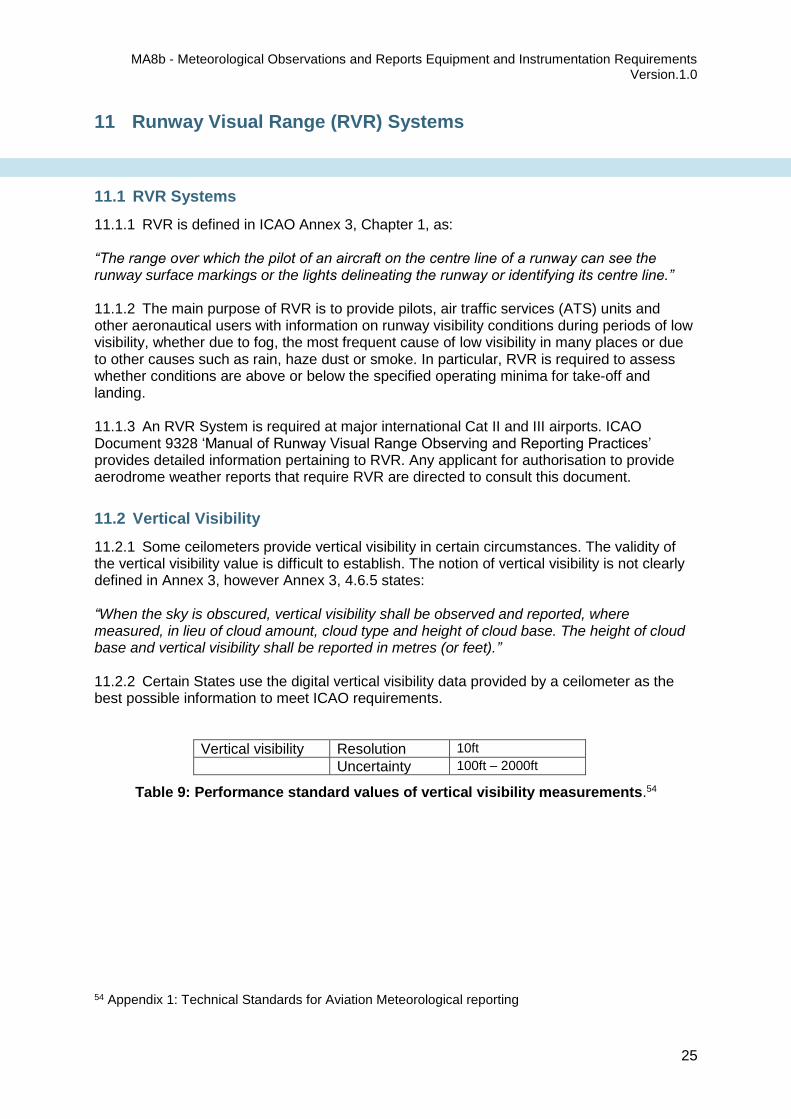
11.2.1 Some ceilometers provide vertical visibility in certain circumstances. The validity of the vertical visibility value is difficult to establish. The notion of vertical visibility is not clearly defined in Annex 3, however Annex 3, 4.6.5 states: “When the sky is obscured, vertical visibility shall be observed and reported, where measured, in lieu of cloud amount, cloud type and height of cloud base. The height of cloud base and vertical visibility shall be reported in metres (or feet).” 11.2.2 Certain States use the digital vertical visibility data provided by a ceilometer as the best possible information to meet ICAO requirements.
Vertical visibility Resolution 10ft
Uncertainty 100ft – 2000ft
Table 9: Performance standard values of vertical visibility measurements.54
54 Appendix 1: Technical Standards for Aviation Meteorological reporting
11 Runway Visual Range (RVR) Systems

MA8b - Meteorological Observations and Reports Equipment and Instrumentation Requirements
Version.1.0
26
12.1.1 AirServices Australia (ASA) requires real time wind, temperature and pressure data to be transmitted directly to relevant ASA offices, as well as the usual METAR/ SPECI data. The type of equipment installed to provide these services is an Automatic Weather Station (AWS). This equipment provides near real-time measurement of wind direction and speed, dry bulb temperature, dew point temperature, QFE, QNH, QFF and rainfall total.55 12.1.2 Rainfall is recorded by the AWS Tipping Bucket Rain Gauge (TBRG). Rainfall amounts reported include the cumulative totals in the:
1. ten minutes prior to the observation 2. sixty minutes prior to the observation, and 3. total recorded since 0900 local time.
12.1.3 The amounts are recorded to a tenth of a millimetre, in increments of 0.2mm. Eg 12.4mm
Resolution 0.2mm
Uncertainty 0.2mm for ≤ 5mm ± 2% for > 5mm
Table10: Performance standard values for rainfall measurement.56
55 Surface Observations Handbook, Vol 3, Chapt 14.1, paras 2 & 3 56 Appendix 1: Technical Standards for Aviation Meteorological reporting
12 Rainfall

MA8b - Meteorological Observations and Reports Equipment and Instrumentation Requirements
Version.1.0
27
Bureau of Meteorology (http://www.bom.gov.au/inside/services_policy/pub_ag/aws/aws.shtml)
Bureau of Meteorology – Equipment Specification A2669 – Digital Telemetry System Equipment Data Formats
ICAO Annex 3 – Meteorological Service for International Air Navigation
ICAO Annex 3, Attachment A57, Operational Desirable Accuracy of Measurement or Observations
ICAO Doc 9328 – Manual of Runway Visual Range Observing and Reporting Practices
ICAO Doc 9837 – Manual on Automatic Meteorological Observing Systems at Aerodromes
ISO Guidance for the Expression of Uncertainty in Measurement
MA8(a) – Instrument Siting Requirements for Automatic Weather Stations (AWS)
MA9(a) – Qualifications and Competencies – Aerodrome Weather Observers
WMO Publication No. 858, Guide to Meteorological Instruments and Methods of Observation, Part I, Measurement of Meteorological Variables.
Guidance is also provided in WMO Publication No. 8, Part II, Observing Systems o Chapter 1 - Measurement of Automatic Weather Stations o Chapter 2 - Measurement and Observations at Aeronautical Meteorological Stations
57 http://www.wmo.int/pages/prog/www/ISS/Meetings/CT-MTDCF-ET-DRC_Geneva2008/Annex3_16ed.pdf 58 http://www.wmo.int/pages/prog/www/IMOP/publications/CIMO-Guide/CIMO_Guide-7th_Edition-2008.html
References

MA8b - Meteorological Observations and Reports Equipment and Instrumentation Requirements
Version.1.0
28
Meteorological Authority Office Strategy, Parliamentary, International and Communication Branch Bureau of Meteorology GPO Box 1289 MELBOURNE VIC 3001 Phone: +61 3 9669 4000 Email: [email protected]
Contact details

MA.8b Meteorological Observations and Reports Equipment and Instrumentation Requirements - Version.1.0
29
Appendix 1: Technical Standards for Aviation Meteorological Reporting.
Meteorological Elements
METAR/SPECI Requirements M – Mandatory C – Conditional O – Optional
References
Sampling period/ Report interval
Reported Resolutioni
Required Measurement UncertaintyII
Comments
Wind Direction
M Table A.3-2 Annex 3
ICAO Doc 9837, 3.3.9 1 min 1° ±10°
Reported in METAR in Degrees True. (measured at 10m ± 1m – Annex 3, 4.1.1.1)
Wind Speed
M Table A.3-2 Annex 3 1 min 1kt
± 1kt up to 10kt, ± 10% above 10kt
Australian standard is to report in Knots (kt) (measured at 10m ± 1m)
Wind Gusts (Maximum & minimum) M Table A.3-2 Annex 3 ICAO Doc. 9837, 3.3.7.1
1 min 1kt
Maximum wind speed averaged over period of 3 seconds. (Annex 3, 4.1.3.2)
Visibility M Table A.3-2 Annex 3 1 min 10m ± 50m up to 600m, ± 10% between 600m & 1500m, ± 20% above 1500m
Instrument measurement at height of 2.5m. (Annex 3, 4.2.1.1)
RVR C Table A.3-2 Annex 3 1 min 0000 ≤ RVR < 400 m, 25m59 0400 ≤ RVR < 0800 m, 50m 0800 ≤ RVR <2000m, 100m
± 10m up to 400m ± 25m between 400m and 800m ± 10% above 800m
Assessed at height of 2.5m (Annex 3, 4.3.1.1). Required for Category II and III instrument approach and landing operations. (Annex 3, 4.3.2.1)
Present weather Table A.3-2 Annex 3 Annex 3, 4.4
Precipitation – Drizzle (DZ) M Table A.3-2 Annex 3 on event Yes/no
Rain (RA) M Table A.3-2 Annex 3 on event Yes/no
Snow (SN) M Table A.3-2 Annex 3 on event Yes/no
Snow Grains (SG) C Table A.3-2 Annex 3 on event Yes/no
Ice pellets (PL) C Table A.3-2 Annex 3 on event Yes/No
Hail (GR) C Table A.3-2 Annex 3 on event Diameter in mm Only hail >5mm,
Small hail/Snow pellets (GS) C Table A.3-2 Annex 3 on event Diameter in mm Only small hail/snow pellets < 5 mm
Thunderstorms (TS) M Table A.3-2 Annex 3 on event Yes/No Using lightning detection
Squall (SQ) C WMO No. 306, Vol 1,
12.2.6.4.8 (a) Table A.3-2 Annex 3
1 min 0.1 m/s
A sudden increase of wind speed of at least 16 knots, the speed rising to 22 knots or more and lasting for at least one minute.
Precipitation event
intensity light (-) moderate, heavy (+)
C Table A.3-2 Annex 3 1min 0.2 mm/hr*
Moderate Dz: 0.2 – 0.4mm/hr60 Heavy Dz> 0.4mm/hr Moderate Rain: 2.2 - 6.0mm/hr Heavy Rain: 6.0 – 50mm/hr
# Evaluated using present weather sensor * Rates based on 10min averaging interval. Ref ICAO 9837, 6.4.2.2
Freezing precipitation Freezing rain (FZRA) M Table A.3-2 Annex 3 on event 2.0mm/h threshold recommended
(ICAO 9837, Chapt 6.3)
Freezing drizzle (FRDZ) M Table A.3-2 Annex 3 on event
Obscuration to visibility (Hydrometeors)
Fog (FG) M Table A.3-2 Annex 3 on event Yes/No Visibility < 1000m
59 ICAO Doc 9328, Table 11.3 60 SOH, Vol 2, Chapt 8.1, para 12. (ICAO Doc 9837, Chapt 6, table 6.1differs)

MA.8b Meteorological Observations and Reports Equipment and Instrumentation Requirements - Version.1.0
30
Meteorological Elements
METAR/SPECI Requirements M – Mandatory C – Conditional O – Optional
References
Sampling period/ Report interval
Reported Resolutioni
Required Measurement UncertaintyII
Comments
Mist (BR) M Table A.3-2 Annex 3 on event Yes/No 1000 ≤ Visibility < 5000m
Freezing Fog (FRFG) M Table A.3-2 Annex 3 on event Yes/No Visibility < 1000m
Obscuration to visibility (Lithometeors)
Haze (HZ) M Table A.3-2 Annex 3 on event Yes/No Visibility < 5000m
Smoke (FU) C Table A.3-2 Annex 3 on event Yes/No Visibility < 5000m
Dust (DU) C Table A.3-2 Annex 3 on event Yes/No Visibility < 5000m
Sand (SA) C Table A.3-2 Annex 3 on event
Yes/No Visibility < 5000m (Only reported if
drifting (DR) <2m above ground61)
Cloud Height M Table A.3-2 Annex 3 1 min 10 ft ± 30ft up to 330ft ± 10% above 330ft
Amount M Table A.3-2 Annex 3 1 min 1 okta ± 1 okta
Type (CB & TCU) M Table A.3-2 Annex 3 1 min 1 okta ± 1 okta
Vertical visibility C Table A.3-2 Annex 3 1 min 10 ft 100 ft – 2000ft Reported where instrumentation is
available
Dry bulb Temperature M Table A.3-2 Annex 3 1 min 0.1°C ± 1.0°C Annex 3, Appendix 3,4.6.2.1
Humidity O Table A.3-2 Annex 3 1 min 1 % 0 - 100% ± 5%
Not required in METAR, but measured and used to derive Dew-point temperature
Dew point Temperature (derived from Dry bulb and Humidity)
M Table A.3-2 Annex 3 1 min 0.1°C ± 1.0°C Annex 3, 4.6.2.1
Air Pressure Station level pressure (QFE) O Table A.3-2 Annex 3 1 min 0.1 hPa ± 0.3 hPa to 0.5hPa Annex 3, 4.7
ICAO derived Mean Sea level Pressure (QNH)
M Table A.3-2 Annex 3 1 min 0.1 hPa ± 0.3 hPa to 0.5hPa Annex 3, 4.7
Rainfall M AIP Gen 3.5, 12.19.1 1 min 0.2 mm 0.2 mm for ≤ 5mm, ± 2% for > 5mm
Required in Australian METAR
i CIMO Guide Part 1: 1.6.3 (A quantitative expression of the ability of an indicating device to distinguish meaningfully between closely adjacent values of the quantity indicated.) II CIMO Guide, Annex 1.B (Col 5) Recommended measurement uncertainty requirements for general operational use, i.e. of Level II data according to FM 12, 13, 14, 15 and its BUFR equivalents. They have been adopted by all eight technical commissions and are applicable for synoptic, aeronautical, agricultural and marine meteorology, hydrology, climatology, etc. These requirements are applicable for both manned and automatic weather stations as defined in the Manual on the Global Observing System (WMO-No. 544). Individual applications may have less stringent requirements. The stated value of required measurement uncertainty represents the uncertainty of the reported value with respect to the true value and indicates the interval in which the true value lies with a stated probability. The recommended probability level is 95 per cent (k = 2), which corresponds to the 2 σ level for a normal (Gaussian) distribution of the variable. The assumption that all known corrections are taken into account implies that the errors in reported values will have a mean value (or bias) close to zero. Any residual bias should be small compared with the stated measurement uncertainty requirement. The true value is the value which, under operational conditions, perfectly characterizes the variable to be measured/observed over the representative time interval, area and/or volume required, taking into account siting and exposure. (Note :
The term uncertainty has preference over accuracy i.e. uncertainty is in accordance with ISO standards on the uncertainty of measurements (ISO, 1995)).
61 Annex 3, Appendix 3, 4.4.2.6 (c)