era: an efï¬cient rate adaption algorithm with fragmentation
TRANSCRIPT

ERA: An Efficient Rate Adaption Algorithm with
Fragmentation
Saad Biaz, Shaoen Wu
{sbiaz, wushaoe}@auburn.edu
Dept. of Computer Science and Software Engineering
Auburn University
107 Dunstan Hall, Auburn University, AL, 36849-5347, USA
Technical Report CSSE07-04 (June 15, 2007)
Abstract
An effective rate adaptation is one of the main challenges in wireless networks with multi-rate support. This
work aims to design an effective rate adaptation algorithm. To fulfill this goal, we study the behavior of a system
under different rate adaptation operations with simulations, investigate the frame loss nature in rate adaptation
dynamics and analyze the effectiveness of different responses to those frame loss causes with both simulation and
analytic model. Then, based on our observations, we propose an effective rate adaptation algorithm, dubbed ERA,
with frame loss differentiation. This algorithm utilizes a strategy named “fragmenting” to discriminate the loss
causes. It takes into account operations effective in both channel degradation and collision environments. With
extensive simulations, our algorithm demonstrates its outstanding effectiveness and significant improvement over
some of existing algorithms.
I. INTRODUCTION
Unlike its wired counterpart, a wireless medium suffers from unstable conditions resulting from
physical obstacles (e.g. signal fading due to distance, frame collision from simultaneous transmissions,
and interference from other signal source, etc). To yield optimal utilization of scarce wireless resources
under such instability, rate adaptation is indispensable to those networks with multi-rate support. Rate
adaptation is the dynamic estimation process of the wireless channel medium conditions and thereof the

choice of appropriate frame rate that a wireless channel can support.
Rate adaptation in IEEE 802.11 networks has been studied at length through the last decade. These
algorithms can be categorized into strategies requiring or not requiring RTS/CTS frames preceding a
data frame. The former type of algorithms include Auto Rate Fallback by Kamerman and Monteban [1],
Adaptive Auto Rate Fallback by Lacage, et al [2], Qiao, et al [3], and Pavon and Choi [4]. The latter
category includes techniques by Holland et al [5] and Sadeghi, et al [6]. Comparably, rate adaptation
schemes with RTS/CTS are more accurate than those without them because RTS/CTS can implicitly
probe instantaneous channel conditions. However, the RTS/CTS control frames are optional in IEEE
802.11 standard; they are turned on only in case that data frame length is larger than the threshold (2347
recommended in IEEE 802.11). Therefore, more attention is paid to algorithms not requiring RTS/CTS
frames. One major problem of these proposals is that they do not differentiate whether a frame loss is due
to collision or to channel degradation. These schemes systematically respond to frame loss by decreasing
their data rate. While such a response is appropriate for channel degradation, it is not for a loss due to
collision for two reasons: 1) a lower rate worsens the collision because of longer frame transmission time;
2) a lower rate is wasteful and unnecessary as channel conditions may support a higher rate.
Thus, in recent years, more research attention is paid to loss differentiation mechanisms. Collision-
Aware Rate Adaptation (dubbed CARA) by Kim, et al. [7] and Robust Rate Adaptation Algorithm (dubbed
RRAA) by Wong, et al. [8] both explore the idea of turning on RTS/CTS frames after a frame loss to
help diagnose the cause of the frame loss. In Loss Differentiated Rate Adaptation [9], we proposed to
retransmit lost frames at the lowest rate in to perform differentiation. These algorithms achieve better
performance when collisions occur.
However, to the best of our knowledge, there is little work so far that investigates in detail the
effectiveness of rate adaptation in presence of both fading and collision. On one hand, some algorithms
work efficiently in channel degradation with the assumption that frame losses are due to channel
degradation. On the other hand, some algorithms perform better in presence of collisions. For our previous
work, we concluded that it is necessary to design an algorithm that works efficiently in both cases. This
paper addresses such a purpose.
This work proposes an effective rate adaptation algorithm, named ERA. This new scheme diagnoses
the cause of a frame loss by slicing the retransmitted lost frame in two fragments with one very short.

For accurate loss differentiation, it takes into account both the loss rate and the received signal strength
after a frame loss. Then it keeps the rate unchanged for collisions and judiciously adapts the data rate
for channel degradation based on a scheme described later. Through extensive simulations, the proposed
scheme is shown effective for losses due to collisions or channel degradation.
The primary contribution of our paper can be summarized as follows:
• We investigate in-depth different possible collision scenarios and channel degradation to help diagnose
and differentiate the nature of a frame loss.
• We compare different current rate adaptation algorithms to determine those actions that are effective
for channel degradation or for collisions. With these observations, we aim at a new rate adaptation
algorithm.
• We present a robust and effective new rate adaptation algorithm working for both channel fading and
frame collisions. With the fragmentation of the retransmitted lost frame technique and the combination
of loss rate and received signal strength, this strategy achieves a better retransmission efficiency for
lost frames by its effective loss differentiation than existing schemes. It also performs better in
throughput.
The rest of this paper is organized as follows: we review related work in Section II. Section III
presents some relevant background information of IEEE 802.11 DCF basic operation, channel fading
and experiment method. Then, in Section IV we present insight into possible frame loss scenarios and
appropriate actions that should be taken for them. We also study the effectiveness of different rate
adaptation strategies under channel degradation and transmission collision, and conclude some guidance
for an effective rate adaptation algorithm. Our new rate adaptation algorithm is presented in Section V
in detail. In Section VI, our new rate adaptation is at length evaluated over different algorithms with
extensive simulations. We summarize this paper in Section VII.
II. RELATED WORK
We do not intend to cover all rate adaptation work in the past. But, what we survey here are those
typical relevant algorithms and characterize state-of-art work relevant to our paper in this field. In this
section, we partition those prior work into two categories: algorithms without and with loss differentiation.
A. Rate Adaptation Algorithms without Loss Differentiation
The scheme Auto Rate Fallback(ARF) by Kamerman and Monteban [1] is, to our knowledge, the
earliest rate adaptation proposed for IEEE 802.11 based wireless networks. It is simple and intuitive.
When a sender succeeds in 10 transmissions consecutively, it increases the data rate to the higher data
rate. At this new rate, if the sender fails, it falls back to the prior rate immediately. Or, when the sender
fails twice to transmit a data frame, it decreases the data rate to the lower level. This original data rate
adaptation protocol, by its nature, experiences data rate fluctuations periodically in stable environment.
Since then, Adaptive Auto Rate Fallback (AARF) by Lacage, emphet al [2] has been proposed to extend
ARF with adaptive update of the rate increase threshold. With AARF, a sender increases its data rate to a
higher rate after N consecutive successful transmissions. If it fails the first transmission at this new rate,
it falls back to prior rate. At the same time, it doubles the threshold to 2N for the next time rate increase.
By this way, AARF extends the time to increase rate in a stable channel environment and results in fewer
rate fluctuation than ARF.
Onoe [18] is implemented as a rate adaptation algorithm of IEEE 802.11 driver in Linux by MadWifi
organization. It is a credit based algorithm where the credit is updated by the statistics of successful,
erroneous frames and retransmissions during a fixed period of 1000 ms. The data rate is increased only
when the credit reaches the threshold value 10. Same logic holds for rate decrease in case of packet failure.
Thus, it takes long time to update the data rate. Consequently, it is legacy to respond to fast change in
wireless channel.
SammpleRate by Bicket [19] starts up at the highest rate and decreases the rate if it experiences four
consecutive transmission failures. To test higher rate supported, it chooses a random rate higher than the
current rate for every tenth frame. It also adapts the data rate upon the history performance by sampling
and recording the statistics of the successive failures, successful transmissions and transmitting time. The
stale sample are removed by a windowing mechanism. It attempts to find the data rate that has the smallest
predicted average transmission (including retransmission) time.
B. Rate Adaptation Algorithms with Loss Differentiation
In recent years, more rate adaptation research effort takes into account collision in frame loss and focus
on the differentiation of the frame loss between channel degradation and collision.

Robust Rate Adaptation Algorithm (dubbed RRAA) by Wong, et al. [8] is a frame loss rate driven
scheme with loss differentiation. It keeps short term frame loss rates, and adapts the transmission
rate accordingly. Beyond that, the authors also proposed “Adaptive RTS Filter” to assess new channel
conditions. RTS/CTS are usually turned off; but when a certain number of frames are lost, the RTS frame
is turned on to probe channel quality. The authors argue that “Adaptive RTS Filter” is helpful to “prevent
collision losses from triggering rate decrease”.
Another rate adaptation strategy aware of collision is proposed by Kim, et al. [7], named CARA. CARA
also requires RTS/CTS probing. If a data frame fails without RTS, RTS probing is turned on. CARA
assumes that all RTS frames at basic rate are resilient to channel fading and concludes that RTS/CTS
transmission failures are caused by collision. On the other hand, if RTS is transmitted successfully, but
the transmission of the following data frame at higher rate fails then this failure is attributed to channel
degradation, and CARA decreases the data rate as in ARF. CARA does not consider the scenario where
an RTS frame could be lost due to a receiver node moving out of radio range.
Almost at the same time of work RRAA and CARA, we also proposed a rate adaptation with loss
differentiation, dubbed LDRA [9]. Instead of breaking the compatibility of current RTS/CTS mechanism
in IEEE 802.11, we suggest retransmitting a lost frame directly at the lowest rate to diagnose frame loss
cause, and thereof adjust date rate correspondingly. We also analytically justify in that work the lowest rate
retransmission is fairly efficient in loss differentiation, especially in low SNR environment. But LDRA
adapts rate entirely upon received signal strength. It is shown by SampleRate [19] that the received signal
strength by itself is not accurate enough to select data rate.
III. PRELIMINARIES
This section presents the background information relevant to this paper and the experimentation methods
to evaluate the proposed scheme ERA and compare it with some existing rate adaptation algorithms.
A. Background
1) Basic Distributed Coordination Function: This work will be limited to the widely deployed IEEE
802.11 networks with distributed coordination function (DCF) [10] and considers the DCF basic protocol
without RTS/CTS frames preceding data frames. IEEE 802.11 standard discourages the use of RTS/CTS
frames when the length of a data frame is less than the RTS threshold (2347 recommended). When the

Frag2Frag1
ACK1 ACK2
NAV in Frag1
NAV in ACK1SIFS
Fig. 1. Transmission of Fragments in IEEE 802.11
receiving station gets the data frame, it responds back an ACK acknowledgement frame. If the transmitting
station does not receive this ACK in a preset duration, it assumes the transmitted data frame is lost and
will retransmit it with backing off its access time (assuming the frame loss is from collision). Garg and
Kappes [11] showed that, for VoIP traffic with 160 byte frames, the data frame efficiency drops to about
12% in 802.11b [12] networks at 11 Mbps if RTS/CTS control frames are used. Thus, in most cases,
RTS/CTS are not used by following IEEE 802.11 recommendation.
2) Fragmentation in IEEE 802.11: The time sequence in the fragmentation mechanism of IEEE 802.11
standard is clearly illustrated in Figure 1. The NAV (Network Allocation Vector) in the first fragment
Frag1 represents the duration from the reception of Frag1 to the completion of the ACK frame to
Frag2. And the NAV in the ACK1 (the ACK for the fragment F1) contains the time from the reception
of this ACK1 till the end of the next ACK (ACK2). Therefore, in a collision dominate environment,
if the first fragment is successfully transmitted, the channel should have been cleared for all the rest
fragments of the same frame. Thus, the probable collision is reduced from the whole frame to its first
fragment.
3) Channel Fading Models: We adopt two channel fading models in our simulations: the two-ray
ground and the Ricean model. The two-ray ground model is mainly used to simulate pure collision
scenarios without channel degradation. We use the Ricean model to introduce practical time-varying
wireless channel fading.
The two-ray ground fading model [13] is a large-scale fading model. It only considers the transmission
distance between a transmitter and a receiver. The power of the signal received at the receiver follows:
Pr = PtΓ1
d4(1)
where Pt is the power of the signal at the transmitter; Γ represents the antenna factors, such as the height

and the antenna gains; and d is the distance between the transmitter and the receiver. With the two-ray
ground fading, the signal to noise ratio is constant at the receiver if the receiver and the transmitter are
still.
For the Ricean fading model, we follow the modeling in Sadeghi, et al [6]. With the transmitter power
P , the signal to noise ratio at time tp can be expressed as:
SNR(tp) = Pd(tp)( − β)
γ(tp)
σ2(2)
To reflect the practical fast fading exponent, γ(tp represents the time-varying gain, which is typically a
probability distribution [13]. A practical and accurate distribution for γ(tp is the Ricean distribution [14]:
p(γ) =γ
σ2e( − (
γ
2σ2 + K)I0(2Kγ) (3)
where parameter K represents the strength of the line of sight component in the signal. I0(.) is the
modified Bessel function [13]. When K = 0, the Ricean distribution becomes the Rayleigh distribution,
without line-of-sight component. Therefore, the Ricean fading model is considered a practical channel
fading taking into account the fast fading, and the line of sight component.
B. Experiment Method
Our extensive investigation and evaluation are based on the network simulator ns-2 with various fading
models and network scenarios. IEEE 802.11g [15] is used as the MAC layer because it has more predefined
rates. For the physical layer, we use the parameters of Cisco Aironet 802.11a/b/g cardBus wireless LAN
adapter [16] and assume symmetric links between a station and the access point or other stations. Table I
summarizes the network configurations and parameters used in our simulations; and Table II describes
the main four network topologies and the number of stations (including the access point). Figure 2 shows
the static topology with 17 stations. The evaluation is limited to one hop communication: all stations are
within the radio coverage of the same access point.
IV. ANALYSIS, OBSERVATIONS AND MOTIVATIONS
In this section, we give insight into the effective rate adaptation operations for different channel
conditions. Firstly we analyze the retransmission after a frame loss. Then, we observe the behavior of
network under different adaptation operations by comparing different rate adaptation strategies under
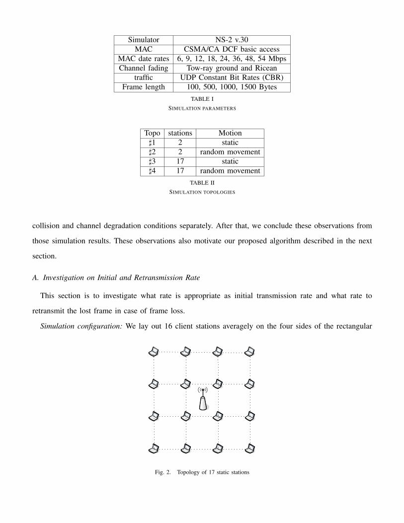
Simulator NS-2 v.30MAC CSMA/CA DCF basic access
MAC date rates 6, 9, 12, 18, 24, 36, 48, 54 MbpsChannel fading Tow-ray ground and Ricean
traffic UDP Constant Bit Rates (CBR)Frame length 100, 500, 1000, 1500 Bytes
TABLE I
SIMULATION PARAMETERS
Topo stations Motion]1 2 static]2 2 random movement]3 17 static]4 17 random movement
TABLE II
SIMULATION TOPOLOGIES
collision and channel degradation conditions separately. After that, we conclude these observations from
those simulation results. These observations also motivate our proposed algorithm described in the next
section.
A. Investigation on Initial and Retransmission Rate
This section is to investigate what rate is appropriate as initial transmission rate and what rate to
retransmit the lost frame in case of frame loss.
Simulation configuration: We lay out 16 client stations averagely on the four sides of the rectangular
Fig. 2. Topology of 17 static stations

network area with the access point at the center. The network area is enlarged gradually to vary the degree
of collision. All client stations constantly transmit saturate CBR traffic to the access point. We evaluate
the performance under two kinds of channel environment: pure collision with the two-ray ground channel
model and the realistic hybrid of collision and channel fading with the Ricean channel model. Three initial
rates are selected: the highest rate (54 Mbps), intermediate rate (24 Mbps) and the lowest rate (6 Mpbs).
Evaluated schemes: Three schemes are evaluated: ARF, ARF-L (ARF modified with the lowest rate
retransmission after frame loss) and ARF-H (ARF modified with halving rate retransmission after frame
loss). These three strategies only differ in the rate selected for retransmission after a frame loss. ARF-L
is modified from ARF, which retransmits the lost frame at the lowest data rate, assuming the loss is from
channel fading. ARF-H is also modified from ARF. But it retransmits the lost frame at the half of the
frame loss data rate, assuming the loss is from channel degradation but not to the poorest.
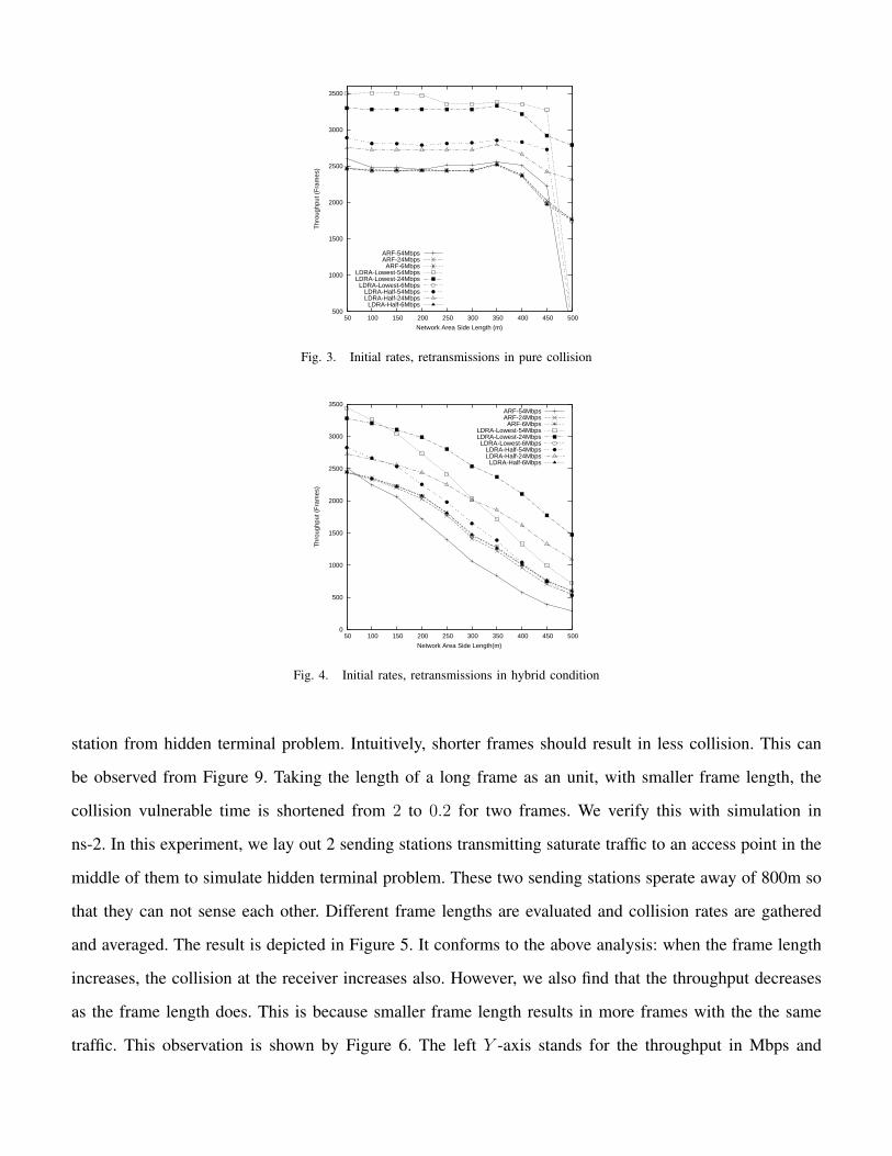
Figure 3 depicts the result in the pure fading channel environment. It shows the highest initial rate
results in best performance for each scheme. And all of them perform almost the same with the lowest
rate as the initial rate. This is because in pure collision environment, it’s difficult for the transmitter to
accumulate enough consecutive successful transmissions to increase data rate due to the frequent frame
loss. Thus these three schemes almost work on the lowest rate all the time. In such case, they have
almost same and the poorest performance. Also, we can observe that ARF-L outperforms other two. This
indicates the lowest rate retransmission is efficient in such environment. However, Figure 4 shows different
trends, which illustrates the consequence of the hybrid realistic channel environment. The initial rate of
intermediate rate performs best in most of the cases, especially when collision degree decreases. ARF
has the worst performance with the highest rate as the initial rate. However, ARF-L still outperforms best
among these three schemes. This hints that the lowest rate retransmission is pretty effective when a frame
loss happens.
B. Relationship of Frame Length and Collision
In IEEE 802.11 networks, there are two well-known problems: exposed terminal problem and hidden
terminal problem. For exposed terminal problem, the carrier sensing of CSMA/CA can help reduce the
potential collision among those sending stations. RTS/CTS is introduced for the hidden terminal problem.
But in most of case, there is no RTS/CTS preceding data frame following IEEE 802.11 recommendation.
Thus, it’s worth studying the relationship between the data frame length and collision at the receiving
500
1000
1500
2000
2500
3000
3500
50 100 150 200 250 300 350 400 450 500T
hrou
ghpu
t (F
ram
es)
Network Area Side Length (m)
ARF-54MbpsARF-24Mbps
ARF-6MbpsLDRA-Lowest-54MbpsLDRA-Lowest-24Mbps
LDRA-Lowest-6MbpsLDRA-Half-54MbpsLDRA-Half-24Mbps
LDRA-Half-6Mbps
Fig. 3. Initial rates, retransmissions in pure collision
0
500
1000
1500
2000
2500
3000
3500
50 100 150 200 250 300 350 400 450 500
Thr
ough
put (
Fra
mes
)
Network Area Side Length(m)
ARF-54MbpsARF-24Mbps
ARF-6MbpsLDRA-Lowest-54MbpsLDRA-Lowest-24Mbps
LDRA-Lowest-6MbpsLDRA-Half-54MbpsLDRA-Half-24Mbps
LDRA-Half-6Mbps
Fig. 4. Initial rates, retransmissions in hybrid condition
station from hidden terminal problem. Intuitively, shorter frames should result in less collision. This can
be observed from Figure 9. Taking the length of a long frame as an unit, with smaller frame length, the
collision vulnerable time is shortened from 2 to 0.2 for two frames. We verify this with simulation in
ns-2. In this experiment, we lay out 2 sending stations transmitting saturate traffic to an access point in the
middle of them to simulate hidden terminal problem. These two sending stations sperate away of 800m so
that they can not sense each other. Different frame lengths are evaluated and collision rates are gathered
and averaged. The result is depicted in Figure 5. It conforms to the above analysis: when the frame length
increases, the collision at the receiver increases also. However, we also find that the throughput decreases
as the frame length does. This is because smaller frame length results in more frames with the the same
traffic. This observation is shown by Figure 6. The left Y -axis stands for the throughput in Mbps and

0
20%
40%
60%
80%
100%
160 300 500 1000 1500
Colli
sion R
ate
Frame Length (Bytes)
Fig. 5. The Relationship of Collision and Frame Length with Hidden Terminals
0.6
0.8
1
1.2
1.4
1.6
1.8
2
0.16 0.3 0.5 1 1.5 2.5 0
0.79
2.3
4.4
8
Thr
ough
put (
Mbp
s)
Thr
ough
put (
KF
ram
es)
Frame Length (KBytes)
ThroughputThe Number of Frame
Fig. 6. The Relationship of Throughput and Frame Length with Hidden Terminals
calibrates for the solid line. And the right Y -axis also represents the throughput but in the number of
received frames and is for the dash line. From the dash line in this figure, a almost constant number of
frames are received when the frame length is larger than 1 KBytes. Thus, their corresponding throughput
in Mbps in the solid line is almost linear. In a conclusion, shorter frame favors to reduce collision, but
results in degradation of throughput.
It’s not surprising that if the transmitting stations can sense each other the collision rate decreases
dramatically because of their carrier sense ability. Such reasoning is confirmed by Figure 7. In this
simulation configuration, the two transmitting stations are separated with 400m so they are within the
radio coverage of each other. The interesting asseveration from this experiment is the collision rate is
almost constant despite of frame length. Thus, as shown in Figure 8, the throughput increases as the

0
2%
4%
6%
8%
10%
160 300 500 1000 1500
Colli
sion R
ate
Frame Length (Bytes)
Fig. 7. The Relationship of Collision and Frame Length with Carrier Sense
1
1.5
2
2.5
3
3.5
4
4.5
5
160 300 500 1000 1500
Thro
ughput (M
bps)
Frame Length (Bytes)
Fig. 8. The Relationship of Throughput and Frame Length with Carrier Sense
frame length because more frames from smaller length results in less network resource efficiency.
C. Analysis of Retransmission
In IEEE 802.11 networks, the frame may get lost due to channel degradation or collision. Since there
are no RTS/CTS frames in DCF basic protocol to probe channel conditions after a frame loss, this work
proposes to use the retransmission itself to diagnose the cause of the loss. In this section, the objective is
to devise effective and efficient retransmission strategies to diagnose the cause of a loss and appropriately
adjust the data rate. Different causes of loss require different reactions.
Channel degradation occurs when two communicating stations move away from each other or the
channel background noise signal increases. In order to cope with channel degradation, the transmission
must use a more robust modulation scheme, resulting in a lower data rate. While a lower data rate is

appropriate and effective to alleviate channel degradation, it is useless for collision. Indeed, a lower data
rate may exacerbate collisions.
Transmission collisions result from high traffic loads. Since a collision may happen at the receiver
without the sender detecting (hidden terminal problem), a sender may not be able to diagnose the cause
of the loss. Note that carrier sensing (CSMA) will not help to diagnose the cause of a loss because a
frame is sent ONLY when the sender did not sense in the first place any competing traffic. Note also that
a wireless node does not keep sensing while sending (no collision detection).
Without RTS/CTS frames to probe channel conditions and CSMA being often useless for our purpose,
we propose to use retransmission strategies to diagnose the loss and to take appropriate actions appropriate
for the loss. When a loss occurs, this work proposes to vary the frame length and to adjust the data rate
to diagnose the cause of a loss and to increase the likelihood of a successful retransmission
1) Smaller Frame Length for Retransmissions: The core idea in our proposed ERA is to fragment the
lost frame: the first fragment is much smaller than the second. Analysis and simulation results support and
confirm two benefits of this fragmentation: a very short frame length increases the likelihood of a successful
retransmission and allows the diagnostic of a loss. We justify in the following why a fragmentation yields
these two benefits:
• Better retransmissions: If a loss was due to a collision, a fragmented retransmission is more likely
to be successful due to two reasons: first, as analyzed and simulated in IV-B, a shorter frame results in
a shorter period of vulnerability (see Figure 9). Therefore, a shorter frame has a lower probability of
collision; second, we exploit a provision of IEEE 802.11 standard for fragmented frames: if the first
fragment is successful, the receiver initiates an acknowledgement frame that acts as a CTS (Clear
to Send). Moreover, the sender needs to wait only for SIFS, instead of DIFS (DIFS > SIFS),
before sending the second fragment. This provision allows the second segment to be sent sooner
(See Figure 1). It should be noted that since shorter frame results in less throughput, the fragmenting
is only suggested to apply to the lost frame, not for all frames.
• Loss diagnosis: If the tiny first fragment is successfully acknowledged, it is a strong indication
that the loss happened due to collisions because a smaller fragment does not compensate fading or
distance.

Fig. 9. Vulnerable time for different frame length
2) Rate Selection for Retransmissions: The retransmission discussed here refers to the very first
retransmission immediately after a frame loss. Current schemes select the data rate after a frame loss
following two strategies. The first strategy consists of maintaining the same rate for the first retransmission
and then decreasing the data rate in case of failure. In general, rate adaptation schemes without loss
differentiation adopt this strategy. The other strategy uses the lowest (basic) data rate for retransmissions.
RRAA and CARA schemes implicitly adopt this strategy because RTS/CTS frames are transmitted at the
lowest rate. LDRA retransmits the whole lost data frame directly at the lowest rate.
At the first glimpse, the lowest rate strategy improves the network performance under collision in those
loss differentiation algorithms RRAA [8], CARA [7] and LDRA [9]. However, it is not the lowest rate
retransmission, but the channel reservation information in the frame retransmitted at the lowest rate, that
enhances the network performance in collision. Indeed, the lowest strategy may increase the complexity
to differentiate frame loss. This analysis is illustrated in Figure 10. As we can observe, if such lowest
rate retransmission succeeds, we can not justify it is from collision or channel degradation, because the
successful retransmission can happen in both cases. Instead, if the retransmission is successfully carried
out at the same rate, it is certain that the loss is from collision (assuming channel does not fluctuate
so quickly just between two consecutive frames; such assumption is reasonable in practical according to
Ricean fading theory [17]). As for the continuous failure of this retransmission, we will discuss more in
later section.
D. Observations

Data
FrameData Frame
Collision
ACK
Frame
Transmitting
Station 1
Receiving
Station 1
Transmitting
Station 2
11 Mbps
1 Mbps
Fig. 10. Successful retransmission at the lowest rate after collision
1) Observations Under Channel Degradation: Observation: Rate adaptation with fewer retransmissions
yields a better performance improvement when few or no collision occurs.
We simulated such a scenario of two static stations on a 500mx500m area: one transmitting and the
other receiving. The Ricean model is used to induce fading and channel degradation. One station keeps
transmitting CBR traffic. The throughput with schemes ARF, CARA, LDRA and m-ARF was respectively
collected. Figure 11 illustrates the results. m-ARF is a scheme that we modified from ARF in which a
station transmits at the constant highest data rate all the time. The Y -axis represents the throughput in
number of frames per second(in kilo frames/s) and the X-axis represents the distance between these two
stations. This figure shows that LDRA performs best, followed by ARF, then CARA. LDRA outperforms
the other schemes because, when a loss happens, LDRA retransmits the lost frame at the lowest data rate,
increasing the likelihood of a successful retransmission. A successful transmission based on the lowest
data rate strongly hints that the loss is due to channel degradation. Consequently, LDRA decreases its
data rate and usually has to retransmit the lost frame only once in case of channel degradation. Meanwhile
ARF has to retransmit a frame at least twice before decreasing its data rate. Although CARA transmits
the RTS at the lowest rate also, it retransmits twice as in ARF. Furthermore, the RTS/CTS exchange
consumes transmission time and results in lower performance in case of channel degradation. We also
find that, the inflexibility of the m-ARF results in almost zero throughput because most of the time the
transmission at the highest data rate can not be supported by the degrading channel.

0
5
10
15
20
25
30
0 100 200 300 400 500T
hrou
ghpu
t (K
Fra
mes
/s)
Transmission Distance (m)
ARFCARALDRA
m-ARF
Fig. 11. Throughput under pure channel degradation
2) Observation Under Collisions: Observation: if a network is congested, a rate adaptation strategy
performs better if it uses short retransmissions to reserve the wireless channel and does not decrease its
rate without a strong indication of channel degradation.
When a collision occurs, a lower data rate does not alleviate network congestion. On the contrary, it
aggravates the problem because a lower data rate results in a larger radio coverage area, leading to more
contention. This observation is confirmed through the following pure collision simulation as illustrated
in Figure 2: sixteen stations and one access point are operating at 54 Mbps with two-ray fading on a
80mx80m area. All stations hear each other and continuously transmit CBR traffic to the access point
so that the network is highly congested. We again compare ARF, CARA, LDRA and a modified ARF
(m-ARF).
m-ARF is introduced only for illustrating how lower data rates hurt network performance in a congested
network (Note that m-ARF performs poorly in a network with pure channel degradation). Figure 12 shows
the results of throughput for the three strategies. From this figure, m-ARF gets the best throughput because
it does not decrease the data rate when a frame is lost in collision. This observation shows that the data
rate should not be blindly decreased after collisions.
CARA outperforms ARF because it uses RTS of very short length to reserve the channel and therefore
reduces the probability of collision as we analyze in Section VI-D. With the same simulation configuration
as in Figure 12, we compare the performance of CARA and LDRA. LDRA retransmits a frame at the
lowest rate like CARA; but it retransmits the entire lost frame every time. From Table III with comparison

2
4
6
8
10
12
16 25 36 49 64 81 100T
hrou
ghpu
t (K
Fra
mes
/s)
The number of client stations
ARFLDRACARA
m-ARF
Fig. 12. Throughput under pure collision
Algorithm Throughput (frames/s)CARA 13165.5LDRA 9942.6
TABLE III
THROUGHPUT WITH MOBILE STATION IN COLLISION
result, althougth both utilize the lowest rate in retransmission, CARA outperforms LDRA in a collision
dominated environment because the RTS it turns on after a frame loss is very short and reduce the
probability of collision, thus favors the retransmission in collision, as concluded in Section VI-D.
E. Motivation and Design Principles
Based on simulation results shown in above Figure 11, ARF slightly outperforms CARA in single hop
transmission under channel degradation dominated environment because CARA does not address channel
degradation. In such channel degradation dominated environment, the use of RTS/CTS frames by CARA
becomes a useless overhead. On the other hand, CARA substantially outperforms ARF in a collision
dominated environment as illustrated in Figure 12 just because CARA reduces collision probability by
using a RTS that is very short to reserve the channel. Such observations motivate a new data rate adaptation
that effectively addresses both channel degradation and network congestion. To achieve such a purpose, it
is necessary that such new rate adaptation correctly differentiates frame losses due to channel degradation
from those due to collisions.
Based on the above analysis and observations, we summarize following design principles for three
different channel conditions:

• when wireless channel supports a constant rate in a stable environment, the rate should be kept
unchanged as long as possible. A higher rate results in frame loss; but a lower rate underutilizes
network resource;
• In channel degradation, the data rate should be decreased to improve SNR;
• In case of collision, the rate should not be changed and short retransmission is helpful in reducing
collision probability.
These three principles are coupled with each other. Such coupling increases the complexity of a rate
adaptation algorithm. Stable environment requires constant rate to optimize resource usage. But algorithms
need to increase rate to test if a higher rate can be supported. When a frame loss happens without accurate
knowledge of the cause, the retransmission at a lower rate favors channel degradation, but underutilizes
network resources in collision. Therefore, a delicate algorithm with accurate differentiation is necessary
for realistic wireless environment.
V. AN EFFECTIVE RATE ADAPTATION ALGORITHM
Keeping concluded design principles in mind, in this section, we divide the discussion of our new
algorithm into two parts: channel condition diagnosis, and the data rate and algorithm parameters
adjustment. Since the accuracy of rate adaptation depends substantially on the diagnosis of channel
condition, the core of this algorithm is to estimate and classify instantaneous channel conditions. After
that, the data rate is increased, decreased, or unchanged upon different diagnosed channel condition.
A. Channel Condition Diagnosis
Specifically, a wireless channel is at any time in one of three conditions: stable channel condition,
channel degradation and network congestion (collision). In this section, we present how our rate adaptation
algorithm ERA diagnoses the channel condition.
Stable channel: In our scheme, an adaptively modified variable Thresholdincr is introduced to help
maintain the data rate for the stable channel. The strategy to diagnose the stable channel is similar to
that in the work AARF. When a station consecutively transmits Thresholdincr frames successfully, it
increases the data rate to test if the channel can support a higher rate. If it succeeds at the new rate,
Thresholdincr is reset to initial value. However, if it fails at the new rate, it falls back to prior rate, and

doubles Thresholdincr to stay at that rate longer before the next time rate upgrade. By this way, the ratio
of frame failure at a higher impractical data rate can be reduced.
However, when a frame loss happens and if the failure data rate is not the new rate just upgraded upon
Thresholdincr, we need to differentiate the loss causes: either channel degradation or network congestions.
According to the analysis and observation in prior sections, we propose “fragmenting” strategy to achieve
such differentiation. In detail, the lost frame is fragmented into two fragments: one short fragment of
Fraglen bytes and the other fragment of the rest of the lost frame. Then, the short fragment is retransmitted
at the failure rate to probe the channel.
• Network congestion: If the transmission of this short fragment succeeds, the frame loss is justified
from collision because this short fragment is at the same rate as the lost frame. According to IEEE
802.11, the transmitted short fragment reserves the channel in its frame header for the rest fragment.
Therefore, the fragment of the rest lost frame should not collide with other frames. Such fragmenting
scheme reduces the collision probability and thus improves network performance.
If the short fragment still fails at that rate, this fragment is directly retried the lowest rate. If it still
fails, this failure is inferred from collision also, because it should succeed at the lowest rate (the
most robust modulation) if the frame loss is caused by channel degradation.
However, if it succeeds at the lowest rate, it is not by itself sufficient to justify the loss from channel
degradation, because it is still possible that the last two failures are from collision. It may just be
accidental that this successful retransmission at the lowest rate does not collide with other frames.
Since such reasoning upon loss rate to differentiate loss results in an indefinite loop, we introduce the
received signal strength to help diagnose in such embarrassment. We propose to measure the received
signal strength for each ACK frame at the sender station. If the difference between the received signal
strength of the ACK frame to this successful short fragment at the lowest rate and that of prior ACKs
is not big enough for a lower data rate, the frame loss is still inferred from network congestion.
• Channel Degradation: Following above reasoning, If the difference between the received signal
strength of the ACK frame to the successful short fragment at the lowest rate and that of previous
ACKs is big enough to decease rate to the lower rate, the frame loss is assumed to be caused by
channel degradation.

B. Data Rate and Thresholdincr Updates
When channel stays stable, the date rate and Thresholdincr are updated as stated in last section V-A.
If a frame loss is diagnosed from collision, the rate does not change; but Thresholdincr is reset to its
initial value so that higher rate might be explored quickly. However, if the frame loss is inferred from
channel degradation, the rate decreases to the lower level and Thresholdincr is reset. It should be noted
that Thresholdincr is critical for the performance in a stable channel or degradation environment.
C. ERA Operating Procedures
After the discussion of diagnosis of channel condition and critical parameters update in above sections,
we describe the detail procedures of our proposed rate adaptation algorithm ERA as follows:
1) A station starts its transmission at the intermediate rate (e.g. 24 Mbps for 802.11g). This selection
is inspired by “dichotomic search” in computer algorithm. The data rate can converge quickly to
the realistic rate.
2) If this station transmits Thresholdincr consecutive frames successfully, it increases its data rate to
the higher rate.
3) If the transmission at this new higher data rate succeeds, the station resets Thresholdincr for this
new rate.
4) However, if the transmission fails at the new higher data rate, the data rate falls back to the prior
rate immediately and the station doubles its Thresholdincr.
5) During normal transmission (not at the new increased rate), if a data frame loss happens, the lost
data frame is fragmented into two fragments: one short of Fraglen bytes and the other with the rest
of the lost frame. The short one is retransmitted firstly still at the failure date rate.
6) If the retransmission of this short fragment succeeds, the data rate keeps no change. But
Thresholdincr is reset.
7) If retransmission of this short fragment fails at the failing rate, it is retried then at the lowest
rate (e.g. 6 Mbps). If it still fails, Thresholdincr is reset and the data rate keeps no change. The
retransmission repeats with fragments at the same date rate till it’s successful or timeout.
8) If the short fragment succeeds in transmission at the lowest data rate, the received signal strength
of its ACK frame is measured and compared with that of last received ACK. If their values are not

different enough for two levels of rate, the data rate keeps no change and so does Thresholdincr.
Or, the data rate is decreased to lower level and Thresholdincr is reset.
VI. SYSTEM EVALUATION
We evaluate our algorithm together with ARF and CARA in pure channel degradation, pure congestion
and general realistic scenarios with both degradation and congestion. The simulation network configuration
and parameters are shown in section III-B. In our simulations, we adopt 64 as the maximum Thresholdincr
and 8 as its initial value. The Fraglen of the short fragment is extremely shortened to the length of RTS
frame. We do not vary the maximum and initial Thresholdincr values in our new algorithm. It should be
noted that it is possible that even better performance can be achieved with delicate adjustment of these
values.
A. Benchmark#0: The Efficiency of Retransmission after Frame Loss
First of all, we compare the efficiency of retransmission after a frame loss between ERA and CARA.
We vary the collision ratio in frame loss and gather the number of retransmissions before each lost frame
is transmitted successfully. Figure 13 depicts the ratio of once retransmission to recover lost frames in
the collected result, where the X-axis represents the collision ratio in frame loss and the Y -axis stands
for the faction of only one retransmission required before the lost frame is successful transmitted. From
this figure, as the collision ratio increases, the ratio of once retransmission in ERA steadily increases as
well. In the extreme case that all frame loss is from collision (the very right of X-axis), ERA needs to
retransmit at almost only once to recover the lost frame. But as for CARA, only 60% lost frames can
transmit successfully with once retransmission. In pure fading (the very left of X-axis), CARA performs
poorly in loss recovery because, although it turns on the RTS/CTS at basic rate, the rate for data frame does
not change until twice data frame transmission failures as in ARF. But ERA shows its robustness still.
Further demonstration is shown in Figure 14, which illustrates the mean of the number of retransmissions
collected under different collision ratios. From this figure, ERA performs more efficiently almost in all
frame loss cases than CARA in general.
B. Benchmark#1: Constant Data Rate Environment
We then start our evaluation in static network, which is common in mesh network. The purpose of
this simulation is to evaluate the effectiveness of algorithms in a stable environment. In this experiment,

0
0.2
0.4
0.6
0.8
1
0 0.2 0.4 0.6 0.8 1
Fra
ctio
n of
Ret
rans
mis
sion
at O
nce
Collision Rate
ERACARA
Fig. 13. Efficiency of Loss Recovery at only Once retransmission
1
1.2
1.4
1.6
1.8
2
2.2
2.4
0 0.2 0.4 0.6 0.8 1
Ret
rans
mis
sion
Mea
n
Collision Rate
ERACARA
Fig. 14. The Mean of Retransmission
the network only contains 2 stations: one access point and one client station. The client is static at
different specific locations. The two-ray ground fading model is used to ensure the wireless channel
support constant data rate during communication. The client station transmits CBR traffic continually to
the access point to access point. Figure 15 shows the result of this simulation. The X-axis depicts the
different locations away from the access point and the Y -axis represents the throughput by the number
of frames received successfully at the access point. As expected, our new algorithm performs best among
these three strategies.
The outstanding performance of our ERA is driven by its ability to adaptively update the threshold to
increase data rate. In such stable environment, it results in fewer transmission failures than its counterparts.

0
5
10
15
20
120 180 240 300 360 420 480T
hrou
ghpu
t (K
Fra
mes
/s)
Transmission distance (m)
ERAARF
CARA
Fig. 15. Throughput at constant data rates
Also, because CARA consumes part of resource for RTS/CTS exchange, it decreases the network
utilization in such environment. Such analysis is confirmed in Figure 16, which depicts the adaptation
dynamics of these three algorithms in stable environment with the two-ray ground fading. The client
station is located 300m away from the access point. The channel constantly supports 18 Mbps.
The second scenario is to evaluate the impact of frame length on the performance of different algorithms
in the same stable environment. In this experiment, the client station is located at the location of 300m
away from the access point. Four CBR packet lengths used are 100 bytes, 500 bytes, 1000 bytes and
1500 bytes. The result is illustrated in Figure 17. Our proposed algorithm ERA can improve more with
shorter frame in stable environment. When the traffic rate is the same, shorter frame length results in
more frames, which leaves more “room” for our algorithm to explore its advantage over the others.
C. Benchmark#2: Pure Channel Degradation
Beyond above simulations, we also evaluate these algorithms under pure channel degradation in realistic
environment with Ricean fading model. Except for the channel fading model, all other configuration are
the same as in above constant data rate stable environment experiments. Figure 18 depicts the throughput
improvement of our proposed algorithm over other two counterparts. The throughput improvement is
defined as: ThroughputERA−ThroughputCARAorARF
ThroughputCARAorARF. From this result figure, our algorithm outperforms the other
two when there are multiple rates available to explore under pure channel degradation condition. As the
location is closer to the access point, the throughput of these three strategies is converging. Finally, they
achieve almost the same at the closest location, because they all operate at the highest data rate all the

0
6 9
18
24
36
48
1 1.02 1.04 1.06 1.08 1.1
Da
ta R
ate
(M
bp
s)
Time (s)
ARF
0
6 9
18
24
36
48
1 1.02 1.04 1.06 1.08 1.1
Da
ta R
ate
(M
bp
s)
Time (s)
CARA
0
6 9
18
24
36
48
1 1.02 1.04 1.06 1.08 1.1D
ata
Ra
te (
Mb
ps)
Time (s)
ERA
Fig. 16. Adaptation transient dynamic in channel degradation
0
2
4
6
8
10
12
14
100 500 1000 1500
Thr
ough
put (
KF
ram
es/s
)
Frame Length (Bytes)
ERAARF
CARA
Fig. 17. Impact of frame length

0
5
10
15
20
0 50 100 150 200 250 300 350 400T
hrou
ghpu
t (K
Fra
mes
/s)
Transmission distance (m)
ERAARF
CARA
Fig. 18. Throughput at fluctuating data rates
time at that closest place, no higher data rate for our algorithm to explore. Also, at the most remote
location, most of the time the stations can only support the lowest data rate. There are no multiple rates
supported either, thus no “room” for ERA to explore. Thus the improvement becomes lower also at those
locations.
D. Benchmark#3: Pure Transmission Collision Environment
In this section, all simulations are carried out in networks with 17 static stations: one access point and
16 client stations. Our purpose is to evaluate the performance of our proposed ERA over ARF and CARA
in pure collision environment. All stations are in the same coverage of the access point. We test them in
pure congested networks with constant data rates. To serve such purpose, the two-ray ground fading is
used for the wireless channel, which eliminates the time-varying small scale fading, thus fits in such pure
collision need. All 16 client stations are averagely laid out on the edges of a rectangular area as shown
in Figure 2. The topology rectangular is enlarged gradually in each simulation to reduce the degree of
collision. All client stations keep transmitting 10 Mbps CBR traffic constantly to the access point at the
center of the rectangular area.
Figure 19 shows the simulation results in such scenario. The X-axis stands for the distance of the
edge of the rectangular to the access point at the center, which also reflects the size of this area and
thus the degree of the transmission collision. The Y -axis represents the throughput by the number of
frames successfully transmitted. As we observe from this figure, our proposed algorithm ERA performs
best again, followed by CARA, and then ARF. Especially, as the collision increases (towards the left

0
2
4
6
8
10
80 160 240 320 400 480 560T
hrou
ghpu
t (K
Fra
mes
/s)
Side Length of the topo rectangular (m)
ERACARA
ARF
Fig. 19. Throughput under different levels of collision
side of X-axis), more improvement can be achieved by our proposed algorithm. This can be attributed to
the more accurate loss differentiation ability of our proposed algorithm. In the congested network, such
ability wins more time to retain its data rate, not blindly decrease, when it detects the frame loss is from
a collision. But others strategies unnecessarily decrease the data rate more frequently.
We also evaluate the impact of the frame length on the loss differentiation ability of our proposed
algorithms and CARA. The simulation configuration is the same as in above simulation. Experiments are
carried out with four CBR packet lengths: 100 bytes, 500 bytes, 1000 bytes and 1500 bytes. The result is
illustrated in Figure 20. The X-axis still represents the distance of the edge of the rectangular to the access
point at the center. The Y -axis calibrates the improvement of our proposed algorithm over CARA with
CBR payload of different lengths. This improvement is defined as: ThroughputERA−ThroughputCARA
ThroughputCARA. As we
analyze in section , longer frames are more feasible to collide with each other. This result figure conforms
to such analysis. More improvement can be achieved for longer frames by our proposed algorithm with
“fragmenting” strategy. This also demonstrates our algorithm performs better in case of heavier collision.
E. Benchmark#4: The Environment of Both Channel Degradation and Collision
To evaluate these algorithms in practical channel with both channel degradation and collision, we
introduce the Ricean fading for the wireless channel. We firstly simulate a static network of 17 stations.
All other network configuration is the same as that for Figure 19 above section VI-D. The client stations
traffic is CBR of 1000 bytes. Figure 21 depicts the simulation results. The X-axis shows the distance of

140%
120%
100%
80%
60%
40%
20%
0 80 160 240 320 400 480 560
Thr
ough
put
Side length of the topo rectanglular (m)
100 Bytes500 Bytes
1000 Bytes1500 Bytes
Fig. 20. Impact of frame length on throughput improvement
0
2
4
6
8
10
30 60 90 120 150 180 210
Thr
ough
put (
KF
ram
es/s
)
Side Length of the topo rectangular (m)
ERACARA
ARF
Fig. 21. Throughput under both channel degradation and collision
the edge of the rectangular to the access point at the center. The Y -axis represents the throughput by the
number of frames successfully transmitted. As we can observe from this figure, our proposed strategy
almost doubles the throughput of CARA and almost quadruples that of ARF in the most congested
network (at the most left side of this figure). As the collision becomes sparse (towards to the right side
of X-axis), the improvement decreases; but there is still substantial enhancement achieved. In deed, due
to the accurate loss differentiation of our ERA, the loss from channel degradation in this scenario is
responded differently from the loss due to collision. Thus, it is more effective in those networks with both
channel degradation and collision.
Beyond above static network, we also evaluate these algorithms in mobile network of 17 stations: all
16 client stations are mobile with random velocities and to random destinations with short pause between

parameter valueNetwork Area 350mX350m
Location of Access Point (175m, 175m)Fading Ricean
Velocity 2 m/s to 30 m/sPause Time 1 second
Client Stations 16TABLE IV
NETWORK PARAMETERS FOR MOBILE NETWORK SIMULATIONS
0
20
40
60
80
100
500 1000 1500
Thr
ough
put (
KF
ram
es/s
)
Frame Length (Bytes)
ERACARA
ARF
Fig. 22. Throughput of mobile stations
two movements in a 350mX350m area within the access point radio coverage; but the access point is
statically located at the center of the network. Table IV shows the parameters used in these simulations.
All stations keep transmitting UDP CBR traffic continuously.
The first experiment of mobile networks intends to evaluate the performance of different algorithms with
CBR traffic of different lengths: 500 bytes, 1000 bytes and 1500 bytes. The simulation results are depicted
in Figure 22. The horizontal axis represents the different CBR traffic packet lengths. The vertical axis
shows the throughput of these three algorithms by the number of traffic frames transmitted successfully.
The analysis of the impact of frame length applies to the mobile networks still. Our algorithm improves
more in case of longer frames.
We also collect the adaptation transient dynamics for these three algorithms in the mobile networking
environment. Figure 23 shows a 2-second period of dynamics for one mobile client station. X-axis
represents the time and Y -axis shows the data rate in Mbps. All those line points in the figure depict
only those frames not collided at the receiver (the access point). In each subfigure, the upper line points

represents the practical data rate that the channel can support at that moment. The bottom line points
stands for the data rate that some rate adaptation algorithm estimates. We have following observations:
1) in scenarios with both collision and channel degradation, the frequently fluctuating channel makes it
infeasible for a rate adaptation algorithm to exactly follow the practical data rate; 2) the top subfiure of our
ERA has more line points (not collided frames) than the other two, followed by the subfigure of CARA
and at last that of ARF. This means our proposed algorithm induces fewest collisions among these three.
3) in such hybrid environment of collision and channel degradation, our proposed algorithm estimates
the dynamic data rate closer to the practical one than other two. CARA outperforms ARF mainly for its
ability to reduce collisions with the RTS turned on.
With above extensive simulations in different network topologies and configurations, our proposed
algorithm robustly shows outstanding performance, especially significant under collision. It demonstrates
the effectiveness in both channel degradation and network collision.
VII. CONCLUSION
In this paper, we firstly analyze the frame retransmission after a frame loss, then study the effectiveness
of different existing rate adaptation algorithms separately in channel degradation and transmission collision
with extensive simulations. Based on the observations from those investigations, we suggest some design
principles for different channel conditions. Then, we propose a new algorithm to take actions effective in
both channel degradation and transmission collision. After extensive evaluations, our proposed strategy
meets these design guidance and performs effectively in various network scenarios.
REFERENCES
[1] A. Kamerman and L. Monteban, “WaveLAN II: A high-performance wireless LAN for the unlicensed band,” Bell Labs Technical
Journal, pp. 118–133, 1997.
[2] M. Lacage, M. Manshaei, and T. Turletti, “IEEE 802.11 Rate Adaptation: A Practical Approach,” in MSWiM04, 2004.
[3] D. Qiao, and S. Choi, and K. Shin, “Goodput Analysis and Link Adaptation for IEEE 802.11a Wireless LANs,” IEEE TRANSACTIONS
ON MOBILE COMPUTING, vol. 1, pp. 278–292, 2002.
[4] J. Pavon and S. Choi, “Link Adaptation Strategy for IEEE 802.11 WLAN via Received Signal Strength Measurement,” in ICC, 2003.
[5] G. Holland, N. Vaidya, and P. Bahl, “A rate-adaptive MAC protocol for multi-hop wireless networks,” in In Proceedings of ACM
MOBICOM’01, 2001.
[6] B. Sadeghi, V. Kanodia, A. Sabharwal, and E. Knightly, “Opportunistic Media Access for Multirate Ad Hoc Networks,” in MOBICOM02,
2002.

0 6 9
18 24
36
48 54
8 8.5 9 9.5 10
Data
Rate
(M
bps)
Time (s)
ARFChannel Rate
0 6 9
18 24
36
48 54
8 8.5 9 9.5 10
Data
Rate
(M
bps)
Time (s)
CARAChannel Rate
0 6 9
18 24
36
48 54
8 8.5 9 9.5 10
Data
Rate
(M
bps)
Time (s)
ERAChannel Rate
Fig. 23. Detail adaptation

[7] J. Kim, S. Kim, S. Choi and D. Qiao, “CARA: Collision-Aware Rate Adaptation for IEEE 802.11 WLANs,” in IEEE INFOCOM’06,
Barcelona, Spain, April 2006.
[8] S. Wong, H. Yang, S. Lu and V. Bharghavan, “Robust Rate Adaptation for 802.11 Wireless Networks,” in MobiCom’06, Angeles,
California, USA., September 2006.
[9] S. Wu and S. Biaz, “Loss Differentiated Rate Adaptation in Wireless Networks,” Auburn University, Tech. Rep., 2007.
[10] IEEE802.11, “http://standards.ieee.org/getieee802/ download/802.11-1999.pdf,” 1999. [Online]. Available:
http://standards.ieee.org/getieee802/download/802.11-1999.pdf
[11] S. Garg and M. Kappes, “An Experimental Study of Throughput for UDP and VoIP Traffic in IEEE 802.11b Networks,” in wcnc2003,
2003.
[12] IEEE802.11b, “http://standards.ieee.org/getieee802/ download/802.11b-1999.pdf,” 1999.
[13] Z. Rong and T. S. Rappaport, Wireless Communications: Principles and Practice, 2nd Edition. Prentice Hall, 2002.
[14] ohn Proakis, Digital Communications, 4th ed. McGraw-Hill Companies, 2000.
[15] IEEE802.11, “http://standards.ieee.org/getieee802/download/802.11g-2003.pdf.”
[16] Cisco System, “http://www.cisco.com/en/US/products/hw/wireless/ ps4555/products data sheet09186a00801ebc29.html.”
[17] W. Stallings, Wireless Communications and Networks. Prentice Hall, 2004.
[18] Madwifi., “http://sourceforge.net/projects/madwifi.”
[19] J. C. Bicket, “Bit-rate Selection in Wireless Networks,” Master’s thesis, MASSACHUSETTS INSTITUTE OF TECHNOLOGY, 2005.