erico master catelogue
DESCRIPTION
full description of earthing systemTRANSCRIPT

Railway
IndustrIal
Telecom
Utility
CommerCial
Grounding & BondingFor Electrical Systems

www.erico.com
Facility Electrical ProtectionLightning protection, grounding, equipotential bonding and surge protection are all interdependent disciplines and the focus of the ERITECH® brand of facility electrical protection products. Reliable protection of personnel and structures demands a systematic and comprehensive approach to minimizing threats caused by transients and other system disturbances. For instance, no air terminal can safely capture and arrest the lightning energy without a dependable route to ground. Equally, even the most expensive surge protection device (SPD) will not provide optimum protection if a low-impedance electrical connection to the ground is not present. Additionally, a low-impedance ground system may create hazards to equipment and personnel alike if equipotential bonding is not in place. These interdependent disciplines are best applied when looking at a total facility rather than an individual piece of equipment or a portion of the facility.
Since no single technology can eliminate the harmful effects of lightning or induced-surge transients, ERICO has developed the Six Point Plan of Protection. The concept behind this plan is a holistic and coordinated approach that embraces all aspects of effective facility
electrical protection.
The six interdependent disciplines that form the protection plan are:
1. Capture the lightning strike 2. Convey this energy to ground 3. Dissipate energy into the grounding system 4. Bond all ground points together 5. Protect incoming AC power feeders 6. Protect low voltage data/telecommunications circuits
At ERICO, we offer innovative, efficient grounding and bonding products as well as engineering experience and technical support. With this experience, ERICO is a world-leading authority in the design and construction of permanent, low-impedance grounding systems.
ERICO employs a quality-assurance program to help ensure that detailed procedures required for every step of the operation produce the best possible system for our clients. This attention to detail includes design, materials procurement, manufacturing, installation and testing.
Our research and development capabilities provide continuous design improvement with new and improved products that preempt the challenging requirements of ever-evolving industry applications. Engineering expertise is shared among the other ERICO operations worldwide, to provide a comprehensive global knowledge pool.
Founded in 1903 as the Electric Railway Improvement Company, ERICO developed the CADWELD® exothermic welding process in 1938. CADWELD connections have found industry-wide acceptance as the ultimate grounding and bonding connection. During the 1970s, ERICO pioneered the copper-bonded steel ground rod electrode. Today, ERICO’s range of facility electrical protection products includes ERITECH® ground rods, grounding clamps and accessories, electrical bonding products, ground enhancement material, ground testers, lightning protection components, equipotential mesh and mats, and signal reference grids; low-voltage surge protection devices; and CADWELD® exothermic connections. Te
lec
om
Uti
lity
Co
mm
er
Cia
l
Ra
ilw
ay
Ind
ustr
Ial
www.erico.com 1
Grounding Principles .......................................2 – 10
Grounding System Components ...................11 – 28 Ground Conductors................................................. 12 – 13
Ground Rods and Couplers...................................... 14 – 17
Ground Clamps and Connectors.............................. 18 – 23
Chemical Ground Electodes ..................................... 24 – 25
Ground Enhancement Material ................................ 26 – 29
Grounding Accessories .................................................... 30
Ground Plates.......................................................... 31 – 32
Equipotential Bonding ...................................33 – 62 Grounding Bus Bars ................................................. 34 – 37
Telecom Ground Bars............................................... 38 – 39
Perimeter Grounding Bus Bars ................................. 40 – 41
Equipment Ground Plates ................................................ 42
Equipment Ground Plate Assemblies................................ 43
Aircraft Grounding Receptacles ....................................... 44
Signal Reference Grids ............................................. 45 – 49
Equipotential Mesh and Mats .................................. 50 – 53
Bonding Devices ...................................................... 54 – 55
Copper Bonding Straps ........................................... 56 – 57
Fence Clamp Assemblies ......................................... 58 – 60
Static Grounding and Bonding................................. 61 – 62
Ground Resistance Testers .............................63 – 65 Ground Resistance Testers ....................................... 64 – 65
Technical Information ....................................66 – 68
Table of Contents
CADWELD® is an exothermic welding system for developing permanent welded electrical connections that will never loosen, corrode or increase in resistance. High-quality CADWELD connections are an integral part of the grounding and bonding process. Contact an ERICO representative today to request additional information on CADWELD.
www.erico.com2
It is a fundamental fact that electricity ALWAYS flows to the point of lowest potential. The task is to help ensure that electricity, including faults, lightning and electronic noise, flows to this point with maximum safety to people, while maintaining the reliability of equipment. Therefore we must help ensure the safe, controlled flow of electricity with minimum voltage drop to earth in all cases.
Grounding Codes and Standards
Grounding needs vary according to function. The grounding requirements of a power system will vary from those of electrical equipment, lightning protection or for the proper function of electronic equipment.
Proper installation of appropriate grounding systems requires knowledge of the needs and layout of the facility. Soil characteristics, grounding conductor materials grounding connections and terminations, are significant factors determining the design of a grounding system. Applicable standards and codes must be applied.
While many codes and standards contain minimum grounding and bonding requirements, the design and installation of electrical grounding systems is one of the most important aspects of any electrical distribution system. However, codes and standards are often misunderstood and grounding systems subsequently installed improperly.
Ground: A conducting connection, whether intentional or accidental, between an electrical circuit or equipment and the earth, or to some conducting body that serves in place of the earth.
Earth: The conductive mass of the earth, whose electric potential at any point is conventionally taken as equal to zero. (In some countries the term “ground” is used instead of “earth.”)
There are important reasons why a grounding system should be installed.
1 The most important reason is to help protect people!
2 To help provide protection of structures and equipment from unintentional contact with live conductors.
3 To help support maximum safety from electrical system faults and lightning.
Bonding: The permanent joining of metallic parts to form an electrically conductive path that will ensure electrical continuity and the capacity to conduct any current likely to be imposed.
Basic Definitions
The need to ground!
GR
Ou
nD
InG
pR
InC
IpLE
S
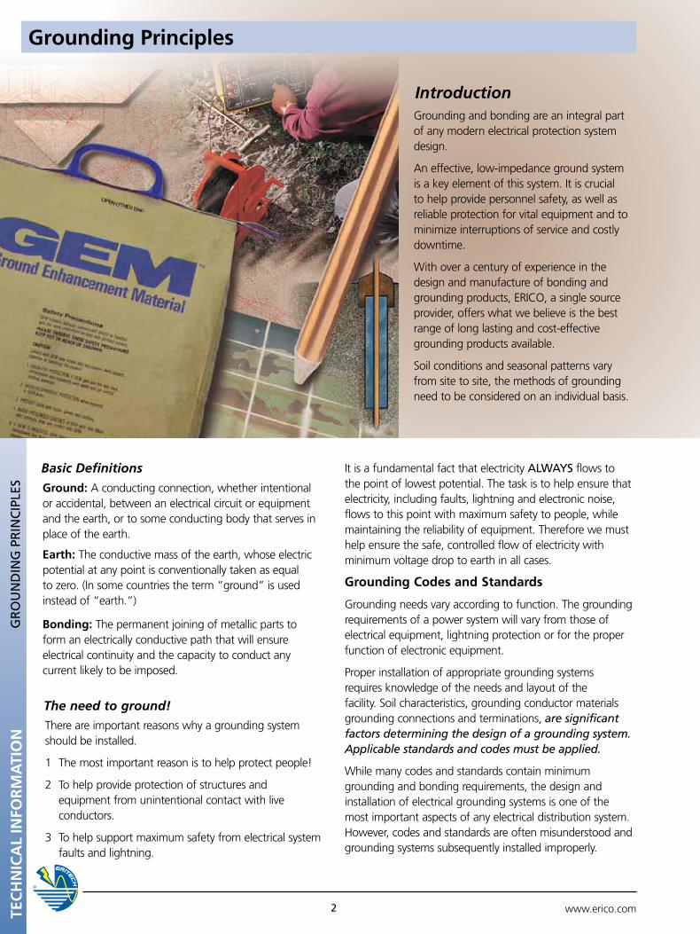
Grounding and bonding are an integral part of any modern electrical protection system design.
An effective, low-impedance ground system is a key element of this system. It is crucial to help provide personnel safety, as well as reliable protection for vital equipment and to minimize interruptions of service and costly downtime.
With over a century of experience in the design and manufacture of bonding and grounding products, ERICO, a single source provider, offers what we believe is the best range of long lasting and cost-effective grounding products available.
Soil conditions and seasonal patterns vary from site to site, the methods of grounding need to be considered on an individual basis.
Introduction
TEC
HN
ICA
L IN
FOR
MA
TIO
N
Grounding Principles
www.erico.com 3 TEC
HN
ICA
L IN
FOR
MA
TIO
N
Why is Good Grounding Important?
The transient nature of lightning with its associated fast rise times and large magnitude currents mean that special consideration needs to be given to grounding, for lightning protection to be effective. Many factors such as soil resistivity variations, installation accessibility, layout and existing physical features are all site specific and tend to affect decisions on grounding methods employed. The primary aim of a direct strike grounding system is to:
• Efficientlydissipatelightningenergyintotheground
• Helpprotectequipmentandpersonnel
Grounding Principles
Low impedance is the key to lightning protection. All grounding connections should be as short and direct as possible to minimize inductance and reduce peak voltages induced in the connections. The ground electrode system must efficiently couple lightning surges into the ground by maximizing capacitive coupling to the soil. The resistance of the ground itself to lightning currents must also be minimized. Only when all these factors are taken into account will maximum lightning protection be achieved.
GR
Ou
nD
InG
pR
InC
IpLE
S
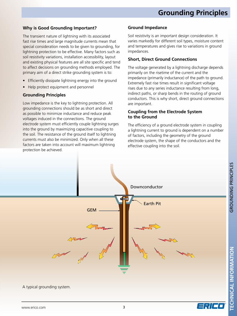
A typical grounding system.
Downconductor
Earth pit
GEM
Grounding Principles
Ground Impedance
Soil resistivity is an important design consideration. It varies markedly for different soil types, moisture content and temperatures and gives rise to variations in ground impedances.
Short, Direct Ground Connections
The voltage generated by a lightning discharge depends primarily on the risetime of the current and the impedance (primarily inductance) of the path to ground. Extremely fast rise times result in significant voltage rises due to any series inductance resulting from long, indirect paths, or sharp bends in the routing of ground conductors. This is why short, direct ground connections are important.
Coupling from the Electrode System to the Ground
The efficiency of a ground electrode system in coupling a lightning current to ground is dependent on a number of factors, including the geometry of the ground electrode system, the shape of the conductors and the effective coupling into the soil.
www.erico.com4
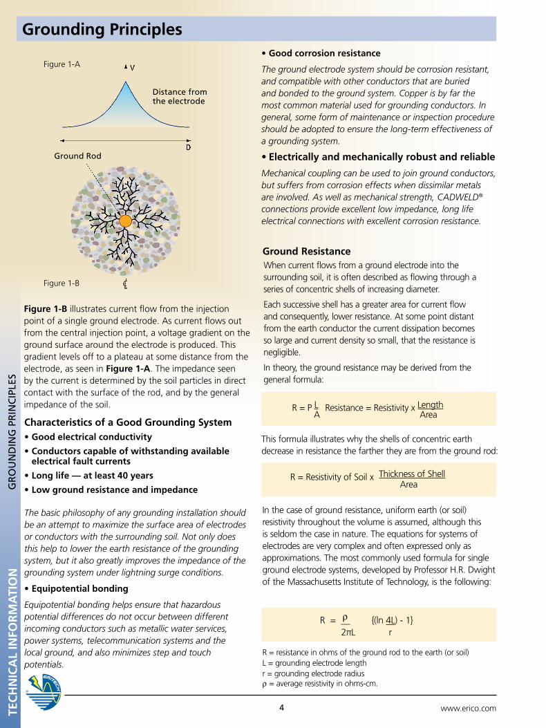
Figure 1-A
Distance from the electrode
Figure 1-B
Ground Rod
Grounding PrinciplesG
RO
un
DIn
G p
RIn
CIp
LES
TEC
HN
ICA
L IN
FOR
MA
TIO
N
Figure 1-B illustrates current flow from the injection point of a single ground electrode. As current flows out from the central injection point, a voltage gradient on the ground surface around the electrode is produced. This gradient levels off to a plateau at some distance from the electrode, as seen in Figure 1-A. The impedance seen by the current is determined by the soil particles in direct contact with the surface of the rod, and by the general impedance of the soil.
Characteristics of a Good Grounding System•Good electrical conductivity
•Conductors capable of withstanding available electrical fault currents
•Long life — at least 40 years
•Low ground resistance and impedance
The basic philosophy of any grounding installation should be an attempt to maximize the surface area of electrodes or conductors with the surrounding soil. Not only does this help to lower the earth resistance of the grounding system, but it also greatly improves the impedance of the grounding system under lightning surge conditions.
•Equipotential bonding
Equipotential bonding helps ensure that hazardous potential differences do not occur between different incoming conductors such as metallic water services, power systems, telecommunication systems and the local ground, and also minimizes step and touch potentials.
•Good corrosion resistance
The ground electrode system should be corrosion resistant, and compatible with other conductors that are buried and bonded to the ground system. Copper is by far the most common material used for grounding conductors. In general, some form of maintenance or inspection procedure should be adopted to ensure the long-term effectiveness of a grounding system.
•Electrically and mechanically robust and reliable
Mechanical coupling can be used to join ground conductors, but suffers from corrosion effects when dissimilar metals are involved. As well as mechanical strength, CADWELD® connections provide excellent low impedance, long life electrical connections with excellent corrosion resistance.
When current flows from a ground electrode into the surrounding soil, it is often described as flowing through a series of concentric shells of increasing diameter.
Each successive shell has a greater area for current flow and consequently, lower resistance. At some point distant from the earth conductor the current dissipation becomes so large and current density so small, that the resistance is negligible.
In theory, the ground resistance may be derived from the general formula:
R = resistance in ohms of the ground rod to the earth (or soil)L = grounding electrode lengthr = grounding electrode radiusρ = average resistivity in ohms-cm.
In the case of ground resistance, uniform earth (or soil) resistivity throughout the volume is assumed, although this is seldom the case in nature. The equations for systems of electrodes are very complex and often expressed only as approximations. The most commonly used formula for single ground electrode systems, developed by Professor H.R. Dwight of the Massachusetts Institute of Technology, is the following:
This formula illustrates why the shells of concentric earth decrease in resistance the farther they are from the ground rod:
Ground Resistance
R = P L Resistance = Resistivity x Length
A
Area
R = Resistivity of Soil x Thickness of Shell
Area
R = __ {(ln 4L) - 1} 2πL r
ρ
www.erico.com 5
Grounding Principles
TEC
HN
ICA
L IN
FOR
MA
TIO
N
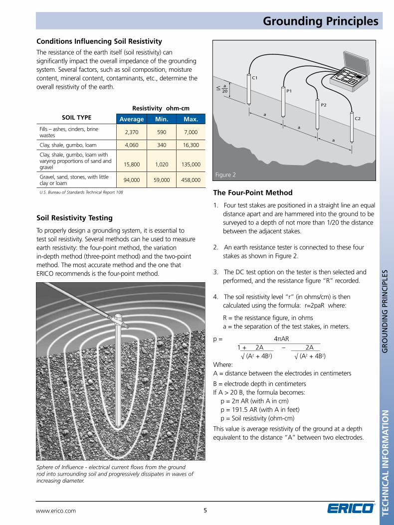
Conditions Influencing Soil ResistivityThe resistance of the earth itself (soil resistivity) can significantly impact the overall impedance of the grounding system. Several factors, such as soil composition, moisture content, mineral content, contaminants, etc., determine the overall resistivity of the earth.
SOIL TYPE
Resistivity ohm-cm
Average Min. Max.
Fills – ashes, cinders, brine wastes 2,370 590 7,000
Clay, shale, gumbo, loam 4,060 340 16,300
Clay, shale, gumbo, loam with varying proportions of sand and gravel 15,800 1,020 135,000
Gravel, sand, stones, with little clay or loam 94,000 59,000 458,000
U.S. Bureau of Standards Technical Report 108
Soil Resistivity Testing
To properly design a grounding system, it is essential to test soil resistivity. Several methods can he used to measure earth resistivity: the four-point method, the variation in-depth method (three-point method) and the two-point method. The most accurate method and the one that ERICO recommends is the four-point method.
R = __ {(ln 4L) - 1} 2πL r
Sphere of Influence - electrical current flows from the ground rod into surrounding soil and progressively dissipates in waves of increasing diameter.
≤
The Four-Point Method
1. Four test stakes are positioned in a straight line an equal distance apart and are hammered into the ground to be surveyed to a depth of not more than 1/20 the distance between the adjacent stakes.
2. An earth resistance tester is connected to these four stakes as shown in Figure 2.
3. The DC test option on the tester is then selected and performed, and the resistance figure “R” recorded.
4. The soil resistivity level “r” (in ohms/cm) is then calculated using the formula: r=2paR where:
R = the resistance figure, in ohms a = the separation of the test stakes, in meters.
p = 4πAR 1 + 2A – 2A √ (A2 + 4B2) √ (A2 + 4B2) Where:A = distance between the electrodes in centimeters
B = electrode depth in centimetersIf A > 20 B, the formula becomes:
p = 2π AR (with A in cm)p = 191.5 AR (with A in feet)p = Soil resistivity (ohm-cm)
This value is average resistivity of the ground at a depth equivalent to the distance “A” between two electrodes.
GR
Ou
nD
InG
pR
InC
IpLE
S
Figure 2
www.erico.com6
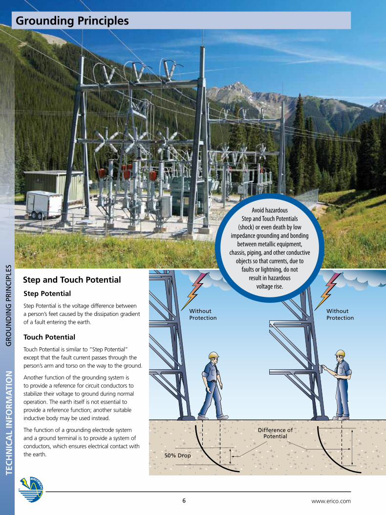
Step and Touch Potential
Without protection
Without protection
Difference of potential
50% Drop
Step Potential
Step Potential is the voltage difference between a person’s feet caused by the dissipation gradient of a fault entering the earth.
Touch Potential
Touch Potential is similar to “Step Potential” except that the fault current passes through the person’s arm and torso on the way to the ground.
Another function of the grounding system is to provide a reference for circuit conductors to stabilize their voltage to ground during normal operation. The earth itself is not essential to provide a reference function; another suitable inductive body may be used instead.
The function of a grounding electrode system and a ground terminal is to provide a system of conductors, which ensures electrical contact with the earth.
Avoid hazardous Step and Touch Potentials
(shock) or even death by low impedance grounding and bonding
between metallic equipment, chassis, piping, and other conductive
objects so that currents, due to faults or lightning, do not
result in hazardous voltage rise.
Grounding PrinciplesTE
CH
NIC
AL
INFO
RM
ATI
ON
GR
Ou
nD
InG
pR
InC
IpLE
S
TEC
HN
ICA
L IN
FOR
MA
TIO
N
www.erico.com 7
Grounding Principles
GR
Ou
nD
InG
pR
InC
IpLE
S
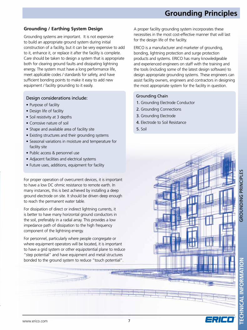
Grounding / Earthing System Design
Grounding systems are important. It is not expensive to build an appropriate ground system during initial construction of a facility, but it can be very expensive to add to it, enhance it, or replace it after the facility is complete. Care should be taken to design a system that is appropriate both for clearing ground faults and dissipating lightning energy. The system must have a long performance life, meet applicable codes / standards for safety, and have sufficient bonding points to make it easy to add new equipment / facility grounding to it easily.
For proper operation of overcurrent devices, it is important to have a low DC ohmic resistance to remote earth. In many instances, this is best achieved by installing a deep ground electrode on site. It should be driven deep enough to reach the permanent water table.
For dissipation of direct or indirect lightning currents, it is better to have many horizontal ground conductors in the soil, preferably in a radial array. This provides a low impedance path of dissipation to the high frequency component of the lightning energy.
For personnel, particularly where people congregate or where equipment operators will be located, it is important to have a grid system or other equipotential plane to reduce “step potential” and have equipment and metal structures bonded to the ground system to reduce “touch potential”.
Design considerations include:•Purposeoffacility
•Designlifeoffacility
•Soilresistivityat3depths
•Corrosivenatureofsoil
•Shapeandavailableareaoffacilitysite
•Existingstructuresandtheirgroundingsystems
•Seasonalvariationsinmoistureandtemperatureforfacility site
•Publicaccess&personneluse
•Adjacentfacilitiesandelectricalsystems
•Futureuses,additions,equipmentforfacility
A proper facility grounding system incorporates these necessities in the most cost-effective manner that will last for the design life of the facility.
ERICO is a manufacturer and marketer of grounding, bonding, lightning protection and surge protection products and systems. ERICO has many knowledgeable and experienced engineers on staff with the training and the tools (including some of the latest design software) to design appropriate grounding systems. These engineers can assist facility owners, engineers and contractors in designing the most appropriate system for the facility in question.
Grounding Chain
1. Grounding Electrode Conductor
2. Grounding Connections
3. Grounding Electrode
4. Electrode to Soil Resistance
5. Soil
TEC
HN
ICA
L IN
FOR
MA
TIO
N
www.erico.com8
GR
Ou
nD
InG
pR
InC
IpLE
S
The Grounding Chain
The performance of the grounding system is determined by the quality of the following five components all of which are of equal importance.
1. The Grounding Electrode Conductor. Typically made from copper or copper-bonded steel, the grounding electrode conductor must be large enough to withstand the maximum available fault current over the maximum clearing time.
2. The Grounding Connections. Often overlooked, the grounding connections are used to tie the elements of the electrode system together. Exothermically welded connections provide a molecular bond that will never loosen or corrode. Mechanical connectors, such as crimp, bolted, and wedge type, rely on physical point-to-point surface contact to maintain the integrity of the electrical connection. IEEE® Standard 837 provides detailed information on the application and testing of permanent grounding connections. ERICO can provide an independent, third-party test report evaluating the performance of these connectors in accordance with the testing procedures set forth in IEEE 837 Standard for Qualifying Permanent Substation Grounding Connections.
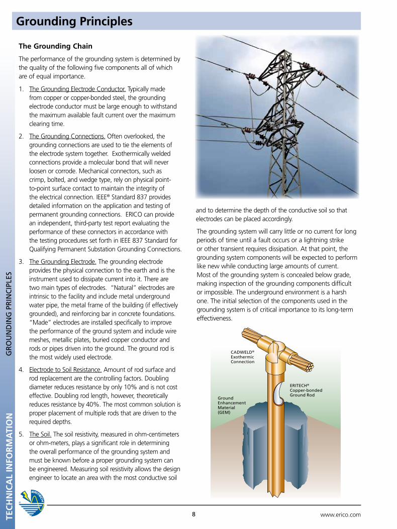
3. The Grounding Electrode. The grounding electrode provides the physical connection to the earth and is the instrument used to dissipate current into it. There are two main types of electrodes. “Natural” electrodes are intrinsic to the facility and include metal underground water pipe, the metal frame of the building (if effectively grounded), and reinforcing bar in concrete foundations. “Made” electrodes are installed specifically to improve the performance of the ground system and include wire meshes, metallic plates, buried copper conductor and rods or pipes driven into the ground. The ground rod is the most widely used electrode.
4. Electrode to Soil Resistance. Amount of rod surface and rod replacement are the controlling factors. Doubling diameter reduces resistance by only 10% and is not cost effective. Doubling rod length, however, theoretically reduces resistance by 40%. The most common solution is proper placement of multiple rods that are driven to the required depths.
5. The Soil. The soil resistivity, measured in ohm-centimeters or ohm-meters, plays a significant role in determining the overall performance of the grounding system and must be known before a proper grounding system can be engineered. Measuring soil resistivity allows the design engineer to locate an area with the most conductive soil
and to determine the depth of the conductive soil so that electrodes can be placed accordingly.
The grounding system will carry little or no current for long periods of time until a fault occurs or a lightning strike or other transient requires dissipation. At that point, the grounding system components will be expected to perform like new while conducting large amounts of current. Most of the grounding system is concealed below grade, making inspection of the grounding components difficult or impossible. The underground environment is a harsh one. The initial selection of the components used in the grounding system is of critical importance to its long-term effectiveness.
Ground Enhancement Material (GEM)
CADWELD® Exothermic Connection
ERITECH® Copper-bonded Ground Rod
Grounding Principles
TEC
HN
ICA
L IN
FOR
MA
TIO
N
www.erico.com 9
Ground System Components
GR
Ou
nD
SY
STEM
CO
MpO
nEn
TS
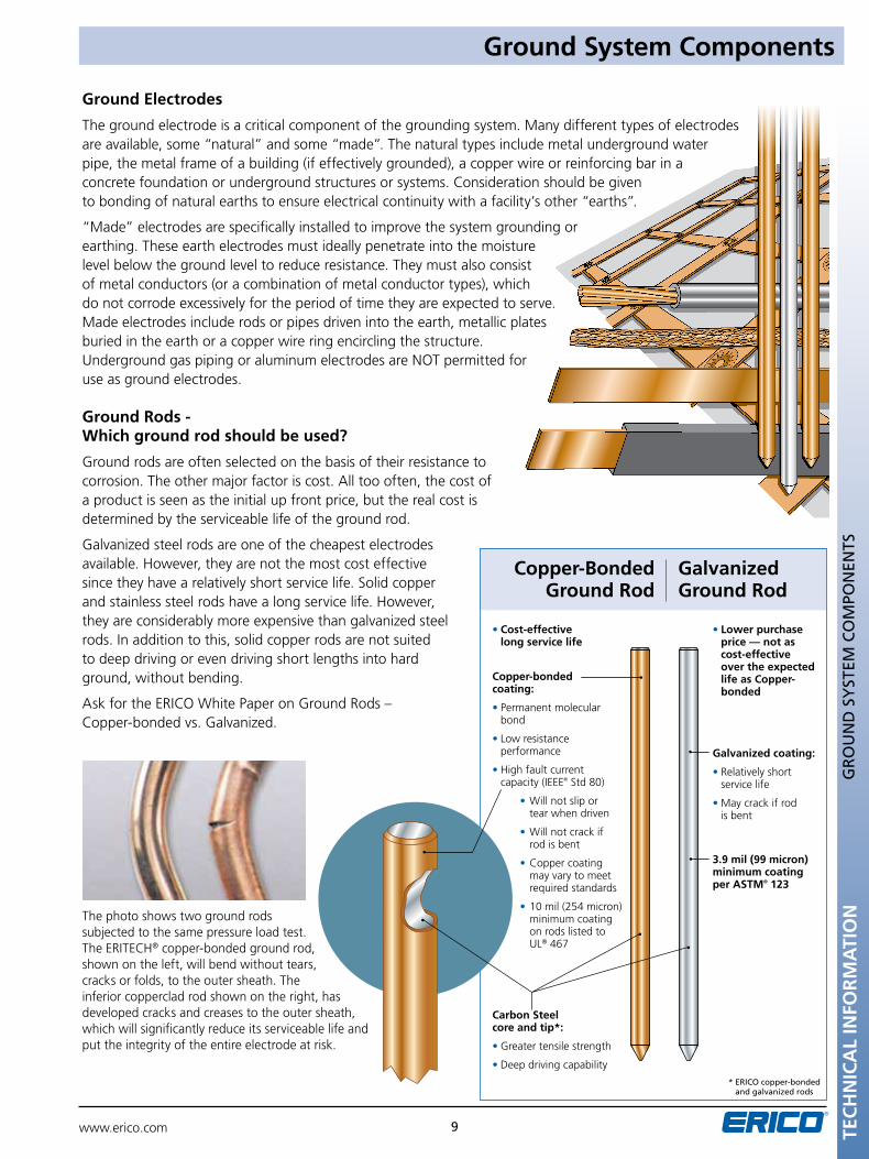
Copper-Bonded Ground Rod
Galvanized Ground Rod
• Cost-effective long service life
Copper-bonded coating:
• Permanent molecular bond
• Low resistance performance
• High fault current capacity (IEEE® Std 80)
• Will not slip or tear when driven
• Will not crack if rod is bent
• Copper coating may vary to meet required standards
• 10 mil (254 micron) minimum coating on rods listed to UL® 467
Carbon Steel core and tip*:
• Greater tensile strength
• Deep driving capability
• Lower purchase price — not as cost-effective over the expected life as Copper- bonded
Galvanized coating:
• Relatively short service life
• May crack if rod is bent
3.9 mil (99 micron) minimum coating per ASTM® 123
* ERICO copper-bonded and galvanized rods
Ground Electrodes
The ground electrode is a critical component of the grounding system. Many different types of electrodes are available, some “natural” and some “made”. The natural types include metal underground water pipe, the metal frame of a building (if effectively grounded), a copper wire or reinforcing bar in a concrete foundation or underground structures or systems. Consideration should be given to bonding of natural earths to ensure electrical continuity with a facility’s other “earths”.
“Made” electrodes are specifically installed to improve the system grounding or earthing. These earth electrodes must ideally penetrate into the moisture level below the ground level to reduce resistance. They must also consist of metal conductors (or a combination of metal conductor types), which do not corrode excessively for the period of time they are expected to serve. Made electrodes include rods or pipes driven into the earth, metallic plates buried in the earth or a copper wire ring encircling the structure. Underground gas piping or aluminum electrodes are NOT permitted for use as ground electrodes.
Ground Rods - Which ground rod should be used?
Ground rods are often selected on the basis of their resistance to corrosion. The other major factor is cost. All too often, the cost of a product is seen as the initial up front price, but the real cost is determined by the serviceable life of the ground rod.
Galvanized steel rods are one of the cheapest electrodes available. However, they are not the most cost effective since they have a relatively short service life. Solid copper and stainless steel rods have a long service life. However, they are considerably more expensive than galvanized steel rods. In addition to this, solid copper rods are not suited to deep driving or even driving short lengths into hard ground, without bending.
Ask for the ERICO White Paper on Ground Rods – Copper-bonded vs. Galvanized.
The photo shows two ground rods subjected to the same pressure load test. The ERITECH® copper-bonded ground rod, shown on the left, will bend without tears, cracks or folds, to the outer sheath. The inferior copperclad rod shown on the right, has developed cracks and creases to the outer sheath, which will significantly reduce its serviceable life and put the integrity of the entire electrode at risk.
TEC
HN
ICA
L IN
FOR
MA
TIO
N
www.erico.com10
Ground System ComponentsG
RO
un
D S
YST
EM C
OM
pOn
EnTS
Copper-Bonded Ground Rod The copper-bonded ground rod has an electrolytic coating of copper deposited over a layer of nickel. This process ensures a long lasting, molecular bond between the copper layer and the steel core. ERICO recommends copper-bonded ground rods because the copper coating will not slip or tear when driven, nor will it crack if the rod is bent. The tough, carbon steel core has good characteristics for deep driving. Copper-bonded ground rods have a high resistance to corrosion and provide a low resistance path to ground.
The Stainless Steel Ground Rod Option It is important to note that certain soils and land fill areas may not be compatible with copper. In these situations, stainless steel is a better proposition. Stainless steel may also be an alternative, where structures or components, such as steel towers, poles or lead sheathed cables are in close proximity to an array of ground electrodes. In these circumstances, consideration must be given to the consequence of galvanic corrosion. The high cost of stainless steel rods prohibits their widespread use.
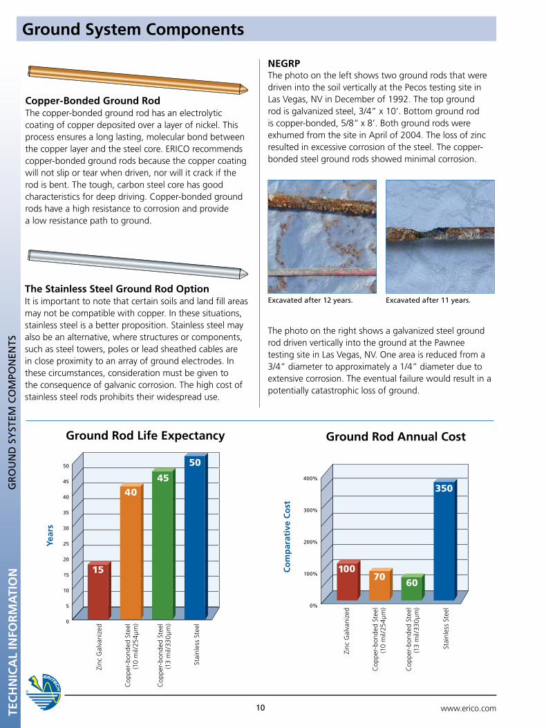
The photo on the right shows a galvanized steel ground rod driven vertically into the ground at the Pawnee testing site in Las Vegas, NV. One area is reduced from a 3/4” diameter to approximately a 1/4” diameter due to extensive corrosion. The eventual failure would result in a potentially catastrophic loss of ground.
NEGRPThe photo on the left shows two ground rods that were driven into the soil vertically at the Pecos testing site in Las Vegas, NV in December of 1992. The top ground rod is galvanized steel, 3/4” x 10’. Bottom ground rod is copper-bonded, 5/8” x 8’. Both ground rods were exhumed from the site in April of 2004. The loss of zinc resulted in excessive corrosion of the steel. The copper-bonded steel ground rods showed minimal corrosion.
Excavated after 12 years. Excavated after 11 years.
Year
s
50
45
40
35
30
25
20
15
10
5
0
Ground Rod Life Expectancy
Cop
per-
bond
ed S
teel
(1
3 m
il/33
0µm
)
Cop
per-
bond
ed S
teel
(1
0 m
il/25
4µm
)
Zinc
Gal
vani
zed
Stai
nles
s St
eel
400%
300%
200%
100%
0%
Ground Rod Annual Cost
Cop
per-
bond
ed S
teel
(1
3 m
il/33
0µm
)
Cop
per-
bond
ed S
teel
(1
0 m
il/25
4µm
)
Zinc
Gal
vani
zed
Stai
nles
s St
eel
Co
mp
arat
ive
Co
st
www.erico.com GR
Ou
ND
ING
SY
STEM
CO
MPO
NEN
TS
11
Grounding System Components
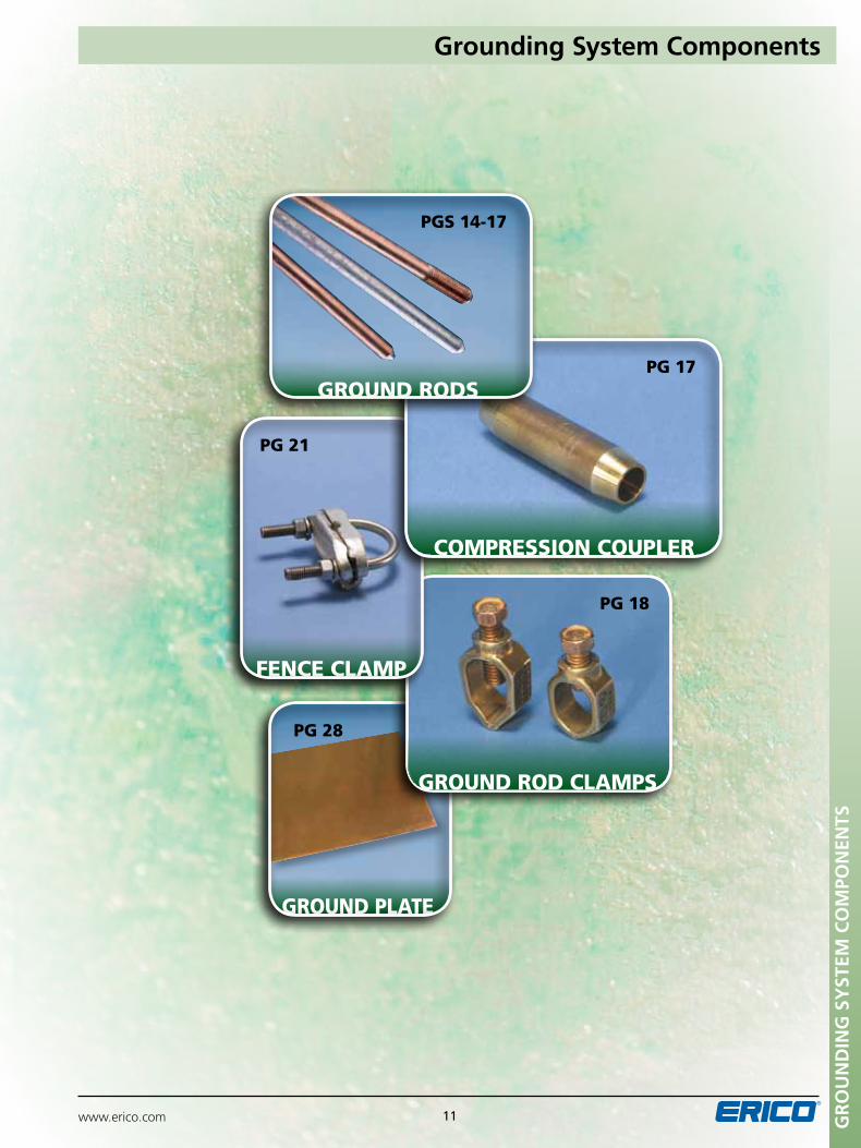
ground plate
pg 18
pg 28
ground rod clamps
fence clamp
Compression Coupler
pg 17
pg 21
Ground rods
pgs 14-17
www.erico.com12GR
Ou
ND
ING
SY
STEM
CO
MPO
NEN
TSG
RO
un
D C
On
Du
CTO
RS
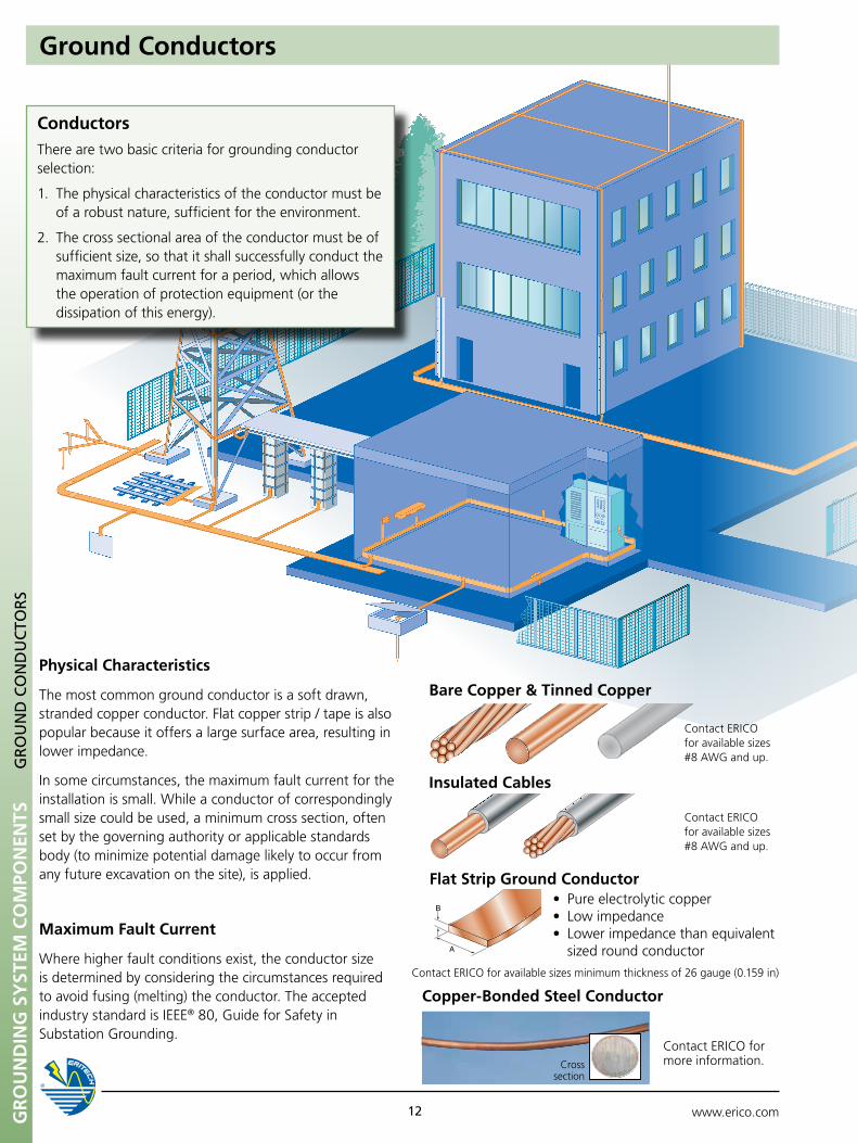
Flat Strip Ground Conductor•Pureelectrolyticcopper•Lowimpedance•Lowerimpedancethanequivalent sized round conductor
Contact ERICO for available sizes minimum thickness of 26 gauge (0.159 in)
ConductorsThere are two basic criteria for grounding conductor selection:
1. The physical characteristics of the conductor must be of a robust nature, sufficient for the environment.
2. The cross sectional area of the conductor must be of sufficient size, so that it shall successfully conduct the maximum fault current for a period, which allows the operation of protection equipment (or the dissipation of this energy).
Physical Characteristics
The most common ground conductor is a soft drawn, stranded copper conductor. Flat copper strip / tape is also popular because it offers a large surface area, resulting in lower impedance.
In some circumstances, the maximum fault current for the installation is small. While a conductor of correspondingly small size could be used, a minimum cross section, often set by the governing authority or applicable standards body (to minimize potential damage likely to occur from any future excavation on the site), is applied.
Maximum Fault Current
Where higher fault conditions exist, the conductor size is determined by considering the circumstances required to avoid fusing (melting) the conductor. The accepted industry standard is IEEE® 80, Guide for Safety in Substation Grounding.
Contact ERICO for available sizes #8 AWG and up.
Bare Copper & Tinned Copper
Contact ERICO for available sizes #8 AWG and up.
Insulated Cables
Ground Conductors
Contact ERICO for more information.
Copper-Bonded Steel Conductor
Cross section
www.erico.com 13
Ground Conductors
GR
Ou
ND
ING
SY
STEM
CO
MPO
NEN
TSG
RO
un
D C
On
Du
CTO
RS
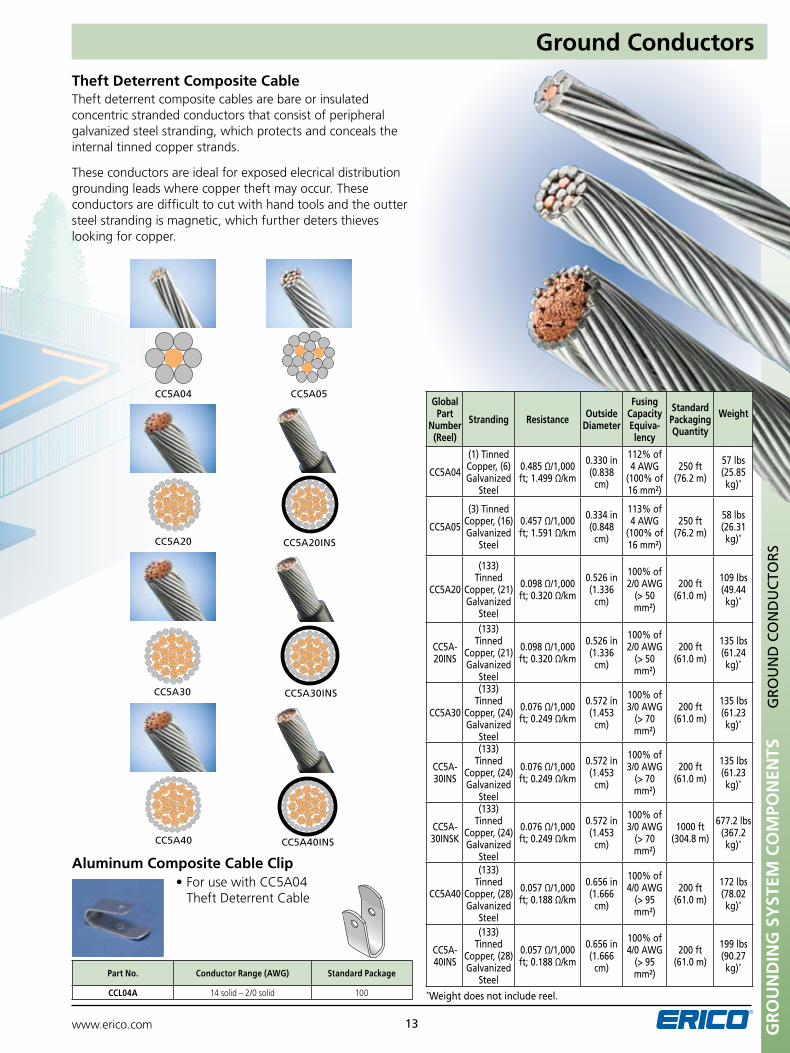
Theft deterrent composite cables are bare or insulated concentric stranded conductors that consist of peripheral galvanized steel stranding, which protects and conceals the internal tinned copper strands.
These conductors are ideal for exposed elecrical distribution grounding leads where copper theft may occur. These conductors are difficult to cut with hand tools and the outter steel stranding is magnetic, which further deters thieves looking for copper.
*Weight does not include reel.
Aluminum Composite Cable Clip•ForusewithCC5A04 Theft Deterrent Cable
Part No. Conductor Range (AWG) Standard Package
CCL04A 14 solid – 2/0 solid 100
Theft Deterrent Composite Cable
CC5A04
CC5A20
CC5A30
CC5A40
CC5A05
CC5A20InS
CC5A30InS
CC5A40InS
Global Part
Number (Reel)
Stranding Resistance Outside Diameter
Fusing Capacity Equiva-lency
Standard Packaging Quantity
Weight
CC5A04
(1) Tinned Copper, (6) Galvanized
Steel
0.485 Ω/1,000 ft; 1.499 Ω/km
0.330 in (0.838
cm)
112% of 4 AWG
(100% of 16 mm²)
250 ft (76.2 m)
57 lbs (25.85 kg)*
CC5A05
(3) Tinned Copper, (16) Galvanized
Steel
0.457 Ω/1,000 ft; 1.591 Ω/km
0.334 in (0.848
cm)
113% of 4 AWG
(100% of 16 mm²)
250 ft (76.2 m)
58 lbs (26.31 kg)*
CC5A20
(133) Tinned
Copper, (21) Galvanized
Steel
0.098 Ω/1,000 ft; 0.320 Ω/km
0.526 in (1.336
cm)
100% of 2/0 AWG
(> 50 mm²)
200 ft (61.0 m)
109 lbs (49.44 kg)*
CC5A-20InS
(133) Tinned
Copper, (21) Galvanized
Steel
0.098 Ω/1,000 ft; 0.320 Ω/km
0.526 in (1.336
cm)
100% of 2/0 AWG
(> 50 mm²)
200 ft (61.0 m)
135 lbs (61.24 kg)*
CC5A30
(133) Tinned
Copper, (24) Galvanized
Steel
0.076 Ω/1,000 ft; 0.249 Ω/km
0.572 in (1.453
cm)
100% of 3/0 AWG
(> 70 mm²)
200 ft (61.0 m)
135 lbs (61.23 kg)*
CC5A-30InS
(133) Tinned
Copper, (24) Galvanized
Steel
0.076 Ω/1,000 ft; 0.249 Ω/km
0.572 in (1.453
cm)
100% of 3/0 AWG
(> 70 mm²)
200 ft (61.0 m)
135 lbs (61.23 kg)*
CC5A-30InSK
(133) Tinned
Copper, (24) Galvanized
Steel
0.076 Ω/1,000 ft; 0.249 Ω/km
0.572 in (1.453
cm)
100% of 3/0 AWG
(> 70 mm²)
1000 ft (304.8 m)
677.2 lbs (367.2 kg)*
CC5A40
(133) Tinned
Copper, (28) Galvanized
Steel
0.057 Ω/1,000 ft; 0.188 Ω/km
0.656 in (1.666
cm)
100% of 4/0 AWG
(> 95 mm²)
200 ft (61.0 m)
172 lbs (78.02 kg)*
CC5A-40InS
(133) Tinned
Copper, (28) Galvanized
Steel
0.057 Ω/1,000 ft; 0.188 Ω/km
0.656 in (1.666
cm)
100% of 4/0 AWG
(> 95 mm²)
200 ft (61.0 m)
199 lbs (90.27 kg)*
www.erico.com14GR
Ou
ND
ING
SY
STEM
CO
MPO
NEN
TS
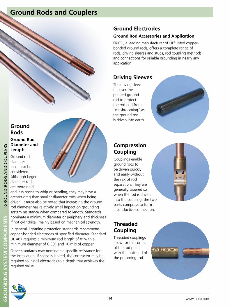
Ground ElectrodesGround Rod Accessories and Application
ERICO, a leading manufacturer of UL® listed copper-bonded ground rods, offers a complete range of rods, driving sleeves and studs, rod coupling methods and connections for reliable grounding in nearly any application.
Driving SleevesThe driving sleeve fits over the pointed ground rod to protect the rod end from “mushrooming” as the ground rod is driven into earth.
Compression CouplingCouplings enable ground rods to be driven quickly and easily without the risk of rod separation. They are generally tapered so when the rod is driven into the coupling, the two parts compress to form a conductive connection.
Threaded CouplingThreaded couplings allow for full contact of the rod point with the butt end of the preceding rod.
Ground Rods Ground Rod Diameter and Length
Ground rod diameter must also be considered. Although larger diameter rods are more rigid and less prone to whip or bending, they may have a greater drag than smaller diameter rods when being driven. It must also be noted that increasing the ground rod diameter has relatively small impact on grounding system resistance when compared to length. Standards nominate a minimum diameter or periphery and thickness if not cylindrical, mainly based on mechanical strength.
In general, lightning protection standards recommend copper-bonded electrodes of specified diameter. Standard UL 467 requires a minimum rod length of 8’ with a minimum diameter of 0.50” and 10 mils of copper.
Other standards may nominate a specific resistance for the installation. If space is limited, the contractor may be required to install electrodes to a depth that achieves the required value.
GR
Ou
nD
RO
DS
An
D C
Ou
pLER
S
Ground Rods and Couplers
www.erico.com 15 GR
Ou
ND
ING
SY
STEM
CO
MPO
NEN
TSG
RO
un
D R
OD
S A
nD
CO
upL
ERS
Ground Rods and Couplers
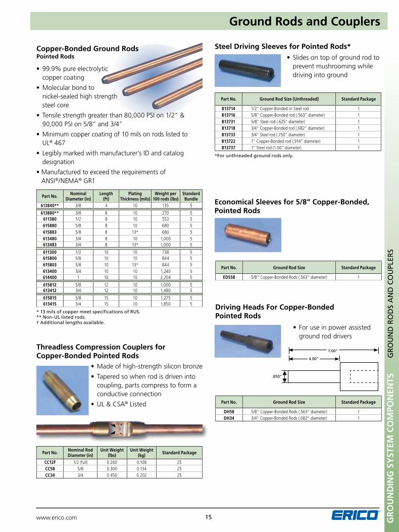
Copper-Bonded Ground RodsPointed Rods
•99.9%pureelectrolytic copper coating
•Molecularbondto nickel-sealed high strength steel core
•Tensilestrengthgreaterthan80,000PSIon1/2”&90,000 PSI on 5/8” and 3/4”
•Minimumcoppercoatingof10milsonrodslistedto UL® 467
•Legiblymarkedwithmanufacturer’sIDandcatalogdesignation
•Manufacturedtoexceedtherequirementsof ANSI®/NEMA® GR1
* 13 mils of copper meet specifications of RuS.** non-uL listed rods.† Additional lengths available.
Part No. Nominal Diameter (in)
Length(ft)
Plating Thickness (mils)
Weight per 100 rods (lbs)
Standard Bundle
613840** 3/8 4 10 135 5
613880** 3/8 8 10 270 5611380 1/2 8 10 553 5615880 5/8 8 10 680 5615883 5/8 8 13* 680 5613480 3/4 8 10 1,000 5613483 3/4 8 13* 1,000 5
611300 1/2 10 10 738 5615800 5/8 10 10 844 5615803 5/8 10 13* 844 5613400 3/4 10 10 1,240 5614400 1 10 10 2,204 5
615812 5/8 12 10 1,000 5613412 3/4 12 10 1,480 5
615815 5/8 15 10 1,275 5613415 3/4 15 10 1,850 5
*For unthreaded ground rods only.
•Slidesontopofgroundrodto prevent mushrooming while
driving into ground
Steel Driving Sleeves for Pointed Rods*
Part No. Ground Rod Size (unthreaded) Standard Package
B13714 1/2” Copper-Bonded or Steel rod 1B13716 5/8” Copper-Bonded rod (.563” diameter) 1B13731 5/8” Steel rod (.625” diameter) 1B13718 3/4” Copper-Bonded rod (.682” diameter) 1B13733 3/4” Steel rod (.750” diameter) 1B13722 1” Copper-Bonded rod (.914” diameter) 1B13737 1” Steel rod (1.00” diameter) 1
Threadless Compression Couplers for Copper-Bonded Pointed Rods
•Madeofhigh-strengthsiliconbronze
•Taperedsowhenrodisdriveninto coupling, parts compress to form a conductive connection
•UL&CSA® Listed
Part No. Nominal Rod Diameter (in)
unit Weight (lbs)
unit Weight (kg) Standard Package
CC12F 1/2 (full) 0.240 0.108 25CC58 5/8 0.300 0.134 25CC34 3/4 0.450 0.202 25
•Foruseinpowerassisted ground rod drivers
Driving Heads For Copper-Bonded Pointed Rods
Part No. Ground Rod Size Standard Package
DH58 5/8” Copper-Bonded Rods (.563” diameter) 1DH34 3/4” Copper-Bonded Rods (.682” diameter) 1
.850”
7.00”
4.00”
Economical Sleeves for 5/8” Copper-Bonded, Pointed Rods
Part No. Ground Rod Size Standard Package
EDS58 5/8” Copper-Bonded Rods (.563” diameter) 1
Gr
ou
nd
inG
SY
STEM
Co
MPo
nEn
TS
www.erico.com16
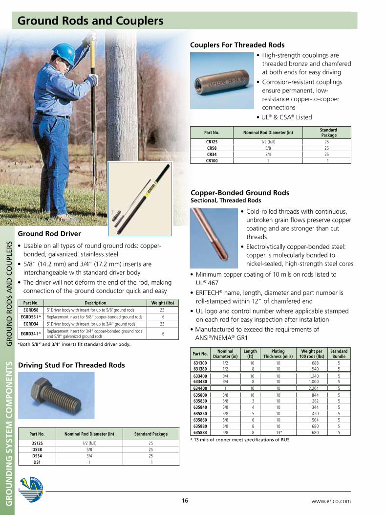
Copper-Bonded Ground RodsSectional, Threaded Rods
•Cold-rolledthreadswithcontinuous,unbroken grain flows preserve copper coating and are stronger than cut threads
•Electrolyticallycopper-bondedsteel: copper is molecularly bonded to
nickel-sealed, high-strength steel cores
•Minimumcoppercoatingof10milsonrodslistedto UL® 467
•ERITECH® name, length, diameter and part number is roll-stamped within 12” of chamfered end
•ULlogoandcontrolnumberwhereapplicablestamped on each rod for easy inspection after installation
•Manufacturedtoexceedtherequirementsof ANSI®/NEMA® GR1
Part No. Nominal Diameter (in)
Length (ft)
Plating Thickness (mils)
Weight per 100 rods (lbs)
Standard Bundle
631300 1/2 10 10 688 5631380 1/2 8 10 540 5
633400 3/4 10 10 1,240 5633480 3/4 8 10 1,000 5
634400 1 10 10 2,204 5
635800 5/8 10 10 844 5635830 5/8 3 10 262 5635840 5/8 4 10 344 5635850 5/8 5 10 420 5635860 5/8 6 10 504 5635880 5/8 8 10 680 5635883 5/8 8 13* 680 5
* 13 mils of copper meet specifications of RuS
Ground Rods and CouplersG
RO
un
D R
OD
S A
nD
CO
upL
ERS
•High-strengthcouplingsarethreaded bronze and chamfered at both ends for easy driving
•Corrosion-resistantcouplings ensure permanent, low-
resistance copper-to-copper connections
•UL®&CSA® Listed
Couplers For Threaded Rods
Part No. Nominal Rod Diameter (in) Standard Package
CR12S 1/2 (full) 25CR58 5/8 25CR34 3/4 25CR100 1 1
Driving Stud For Threaded Rods
Part No. Nominal Rod Diameter (in) Standard Package
DS12S 1/2 (full) 25DS58 5/8 25DS34 3/4 25DS1 1 1
Ground Rod Driver
•Usableonalltypesofroundgroundrods:copper-bonded, galvanized, stainless steel
•5/8”(14.2mm)and3/4”(17.2mm)insertsareinterchangeable with standard driver body
•Thedriverwillnotdeformtheendoftherod,makingconnection of the ground conductor quick and easy
*Both 5/8“ and 3/4“ inserts fit standard driver body.
Part No. Description Weight (lbs)
EGRD58 5’ Driver body with insert for up to 5/8”ground rods 23
EGRD58 I * Replacement insert for 5/8” copper-bonded ground rods 6
EGRD34 5’ Driver body with insert for up to 3/4” ground rods 23
EGRD34 I * Replacement insert for 3/4” copper-bonded ground rods and 5/8” galvanized ground rods 6
www.erico.com 17 GR
Ou
ND
ING
SY
STEM
CO
MPO
NEN
TSG
RO
un
D R
OD
S A
nD
CO
upL
ERS
Couplers for Threaded Stainless Steel Ground Rods
Compression Couplers for Threadless Stainless Steel Ground Rods
Part No. Nominal Rod Diameter (in) Stainless Steel Type Standard Package
CR58SS 5/8 (full) 304 1
CR34SS 3/4 (full) 304 1
Part No. Nominal Rod Diameter (in) Stainless Steel Type Standard Package
CC58SS 5/8 (full) 304 1
CC34SS 3/4 (full) 304 1
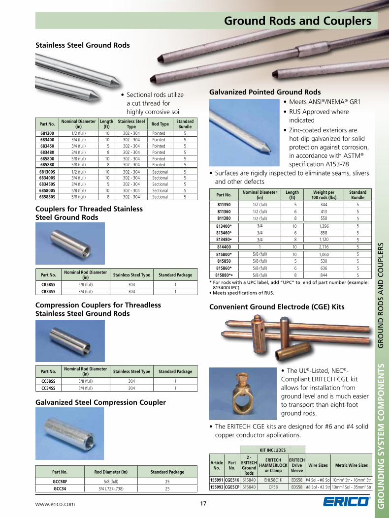
•MeetsANSI®/NEMA® GR1
•RUSApprovedwhereindicated
•Zinc-coatedexteriorsarehot-dip galvanized for solid protection against corrosion, in accordance with ASTM® specification A153-78
•Surfacesarerigidlyinspectedtoeliminateseams,sliversand other defects
* For rods with a upC label, add “upC” to end of part number (example: 813400upC).
•MeetsspecificationsofRUS.
Galvanized Pointed Ground Rods
Part No. Nominal Diameter (in)
Length (ft)
Weight per 100 rods (lbs)
Standard Bundle
811350 1/2 (full) 5 344 5
811360 1/2 (full) 6 413 5811380 1/2 (full) 8 550 5
813400* 3/4 10 1,396 5
813460* 3/4 6 858 5813480• 3/4 8 1,120 5
814400 1 10 2,716 5
815800* 5/8 (full) 10 1,060 5
815850 5/8 (full) 5 530 5
815860* 5/8 (full) 6 636 5
815880*• 5/8 (full) 8 844 5
Galvanized Steel Compression Coupler
Part No. Rod Diameter (in) Standard Package
GCC58F 5/8 (full) 25
GCC34 3/4 (.727-.738) 25
•Sectionalrodsutilizea cut thread for highly corrosive soil
Stainless Steel Ground Rods
Part No. Nominal Diameter (in)
Length (ft)
Stainless Steel Type Rod Type Standard
Bundle 681300 1/2 (full) 10 302 - 304 Pointed 5683400 3/4 (full) 10 302 - 304 Pointed 5683450 3/4 (full) 5 302 - 304 Pointed 5683480 3/4 (full) 8 302 - 304 Pointed 5685800 5/8 (full) 10 302 - 304 Pointed 5685880 5/8 (full) 8 302 - 304 Pointed 5
681300S 1/2 (full) 10 302 - 304 Sectional 5683400S 3/4 (full) 10 302 - 304 Sectional 5683450S 3/4 (full) 5 302 - 304 Sectional 5685800S 5/8 (full) 10 302 - 304 Sectional 5685880S 5/8 (full) 8 302 - 304 Sectional 5
•TheUL®-Listed, NEC®-Compliant ERITECH CGE kit allows for installation from ground level and is much easier to transport than eight-foot ground rods.
•TheERITECHCGEkitsaredesignedfor#6and#4solidcopper conductor applications.
Convenient Ground Electrode (CGE) Kits
KIT INCLuDES
Article No.
Part No.
2 - ERITECH Ground
Rods
ERITECH HAMMERLOCK
or Clamp
ERITECH Drive
SleeveWire Sizes Metric Wire Sizes
155991 CGE51K 615840 EHL58C1K EDS58 #4 Sol - #6 Sol 10mm2 Str - 16mm2 Str
155993 CGE5CP 615840 CP58 EDS58 #8 Sol - #2 Str 10mm2 Sol - 35mm2 Str
Ground Rods and Couplers

www.erico.com18GR
Ou
ND
ING
SY
STEM
CO
MPO
NEN
TSG
RO
un
D C
LAM
pS A
nD
CO
nn
ECTO
RS
Ground Clamps and Connectors
ERITECH® HAMMERLOCK
ERITECH® HAMMERLOCK for 2 Conductors
•Lowresistanceconnection
•Irreversibleconnectionwith excellent mechanical strength
•Fastandsimpleinstallation
•cULusListed
Standard package: 25
Standard package: 25 *not uL® Listed
Part No. Ground Rod Size (in) Conductor Range (AWG)
For Galvalnized Ground Rods
EHL58G2G 5/8 (full) 1/0 stranded – 2/0 stranded
EHL58G1V 5/8 (full) 4 stranded – 2 stranded
EHL58G1K 5/8 (full) 6 solid – 4 solid
EHL34G1V 3/4 4 stranded – 2 stranded
EHL34SG1V* 3/4 4 stranded – 2 stranded
EHL34G1K 3/4 6 solid – 4 solid
EHL34SG1K* 3/4 6 solid – 4 solid
Part No. Ground Rod Size (in) Conductor Range (AWG)
For Copper-bonded Ground Rods
EHL12FC2G 1/2 (full) 1/0 stranded – 2/0 stranded
EHL12FC1V 1/2 (full) 4 stranded – 2 stranded
EHL12FC1K 1/2 (full) 6 solid – 4 solid
EHL58C2G 5/8 1/0 stranded – 2/0 stranded
EHL58C1V 5/8 4 stranded – 2 stranded
EHL58C1K 5/8 6 solid – 4 solid
EHL34C2G 3/4 1/0 stranded – 2/0 stranded
EHL34C1V 3/4 4 stranded – 2 stranded
EHL34C1K 3/4 6 solid – 4 solid
Part No. Ground Rod Size (in) Conductor Range (AWG)
For Copper-bonded Ground Rods
EHL12FC1K1K* 1/2 in 6 solid – 4 solid
EHL58C1K1K* 5/8 in 6 solid – 4 solid
For Galvalnized Ground Rods
EHL58G1K1K* 5/8 in 6 solid – 4 solid
Bronze Ground Rod Clamps•High-strengthsiliconbronze
•Forusewithcopper-bondedgroundrods
•Suitablefordirectburial
•ULListedfordirectburialinearthorconcrete
•CSAListed
∆ HDC58 threads are 1/2“– 13 unC. HDC58R threads are 7/16“ – 14 unC.* not uL Listed† not CSA Listed
Part No. Rod Diameter (in) Conductor Range (AWG)
Standard Package
Standard Duty
CP38† 3/8 10 solid – 2 stranded 100
CP58 1/2 - 5/8 10 solid – 2 stranded 50
CP34 1/2 - 3/4 10 solid – 1/0 stranded 50
Heavy Duty
HDC12 1/2 10 solid – 2 stranded 50
HDC58∆ 5/8 8 solid – 1/0 stranded 50
HDC58R∆ 5/8 8 solid – 1/0 stranded 50
HDC34 3/4 8 solid – 1/0 stranded 25
HDC34SP* 3/4 8 solid – 3/0 stranded 25
HDC1† 1 8 solid – 4/0 stranded 1
www.erico.com 19
Ground Clamps and Connectors
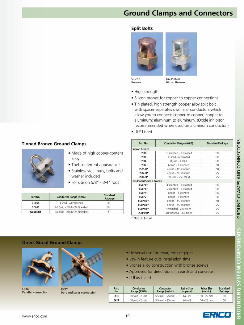
Split Bolts
Silicon Bronze
Tin-plated Silicon Bronze
Part No. Conductor Range (AWG) Standard Package
Silicon BronzeESB8 16 stranded – 8 stranded 100ESB6 10 solid – 6 stranded 100ESB4 8 solid – 4 solid 100ESB2 6 solid – 2 stranded 50
ESB1/0* 4 solid – 1/0 stranded 50ESB2/0* 2 solid – 2/0 stranded 25ESB4/0* 1/0 solid – 250 MCM 25
Tin-Plated Silicon BronzeESBP8* 14 stranded – 8 stranded 100ESBP6* 10 stranded – 6 stranded 100ESBP4* 8 solid – 3 stranded 100ESBP2* 8 solid – 2 stranded 100
ESBP1/0* 6 solid – 1/0 stranded 50ESBP2/0* 8 solid – 2/0 stranded 25ESBP4/0* 4 stranded – 250 MCM 25ESBP350* 3/0 stranded – 350 MCM 25
•Highstrength
•Siliconbronzeforcoppertocopperconnections.
•Tinplated,highstrengthcopperalloysplitboltwith spacer separates dissimilar conductors which allow you to connect: copper to copper; copper to aluminum; aluminum to aluminum. (Oxide inhibitor recommmended when used on aluminum conductor.)
•UL® Listed
Direct Burial Ground Clamps
•Universaluseforrebar,rodsorpipes
•Lay-infeaturecutsinstallationtime
•Bronzealloyconstructionwithbronzescrews
•Approvedfordirectburialinearthandconcrete
•cULusListed
EK16: parallel connection
EK17: perpendicular connection
Part No.
Conductor Range (AWG)
Conductor Range (metric)
Rebar Size (imperial)
Rebar Size (metric)
Standard Package
EK16 10 solid - 2 solid 5.5 mm2 – 25 mm2 #4 – #8 10 – 25 mm 50
EK17 10 solid - 2 solid 5.5 mm2 – 25 mm2 #4 – #8 10 – 25 mm 50
* not uL Listed
Tinned Bronze Ground Clamps
Part No. Conductor Range (AWG) Standard Package
GC064 4 Solid - 2/0 Stranded 50
GC065 2/0 Solid - 250 MCM Stranded 50
GC065TH 2/0 Solid - 250 MCM Stranded 5
•Madeofhighcopper-contentalloy
•Theft-deterrentappearance
•Stainlesssteelnuts,boltsandwasher included
•Foruseon5/8”-3/4”rods
GR
Ou
ND
ING
SY
STEM
CO
MPO
NEN
TSG
RO
un
D C
LAM
pS A
nD
CO
nn
ECTO
RS
www.erico.com20GR
Ou
ND
ING
SY
STEM
CO
MPO
NEN
TS
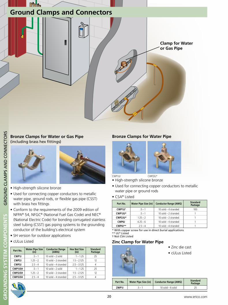
Bronze Clamps for Water or Gas Pipe(including brass hex fittings)
•High-strengthsiliconebronze
•Usedforconnectingcopperconductorstometallicwater pipe, ground rods, or flexible gas pipe (CSST) with brass hex fittings
•Conformtotherequirementsofthe2009editionof NFPA® 54, NFGC® (National Fuel Gas Code) and NEC® (National Electric Code) for bonding corrugated stainless steel tubing (CSST) gas piping systems to the grounding conductor of the building’s electrical system
•SHversionforoutdoorapplications
•cULusListed
Part No. Water Pipe Size (in)
Conductor Range (AWG)
Hex Nut Size (in)
Standard Package
CWP1J .5 – 1 10 solid – 2 solid 1 – 1.25 25
CWP2J 1.25 – 2 10 solid – 2 stranded 1.5 – 2.125 12
CWP3J 2.5 – 4 10 solid – 4 stranded 2.5 – 3.125 4
CWP1JSH .5 – 1 10 solid – 2 solid 1 – 1.25 25
CWP2JSH 1.25 – 2 10 solid – 2 stranded 1.5 – 2.125 12
CWP3JSH 2.5 – 4 10 solid – 4 stranded 2.5 – 3.125 4
•Zincdiecast
•cULusListed
Zinc Clamp for Water Pipe
Part No. Water Pipe Size (in) Conductor Range (AWG) Standard Package
ZWP1J .5 – 1 10 solid – 6 solid 25
GR
Ou
nD
CLA
MpS
An
D C
On
nEC
TOR
S
•High-strengthsiliconebronze
•Usedforconnectingcopperconductorstometallicwater pipe or ground rods
•CSA® Listed
* With copper screw for use in direct burial applications** uL® Listed † not CSA Listed
Part No. Water Pipe Size (in) Conductor Range (AWG) Standard Package
CWP1JJ† .5 – 1 10 solid – 4 stranded 100
CWP1Ju* .5 – 1 10 solid – 2 stranded 1
CWP2Ju* 1.25 – 2 10 solid – 2 stranded 1
CWP6J 4.25 – 6 10 solid – 4 stranded 1
CWP4J** 2.5 – 4 10 solid – 4 stranded 1
CWP1JU CWP2JU*
Bronze Clamps for Water Pipe
Ground Clamps and Connectors
Clamp for Water or Gas Pipe
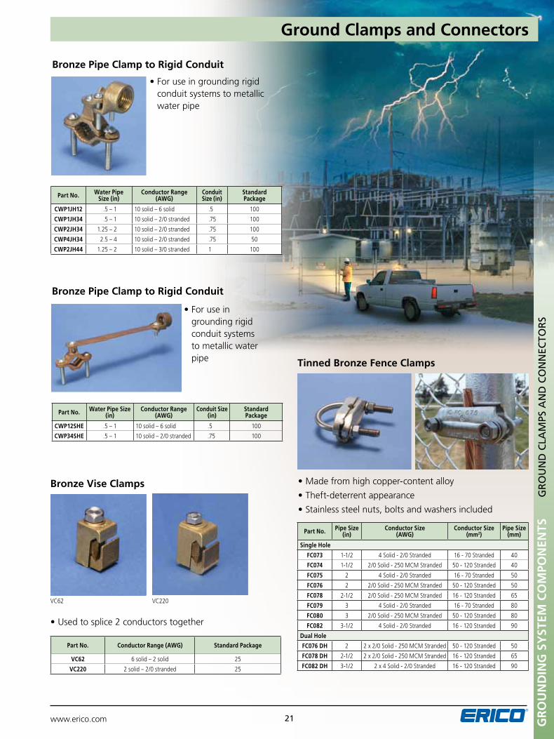
Bronze Pipe Clamp to Rigid Conduit
•Foruseingroundingrigid conduit systems to metallic water pipe
Part No. Water Pipe Size (in)
Conductor Range (AWG)
Conduit Size (in)
Standard Package
CWP1JH12 .5 – 1 10 solid – 6 solid .5 100
CWP1JH34 .5 – 1 10 solid – 2/0 stranded .75 100
CWP2JH34 1.25 – 2 10 solid – 2/0 stranded .75 100
CWP4JH34 2.5 – 4 10 solid – 2/0 stranded .75 50
CWP2JH44 1.25 – 2 10 solid – 3/0 stranded 1 100
•Foruseingrounding rigid conduit systems to metallic water pipe
Part No. Water Pipe Size (in)
Conductor Range (AWG)
Conduit Size (in)
Standard Package
CWP12SHE .5 – 1 10 solid – 6 solid .5 100
CWP34SHE .5 – 1 10 solid – 2/0 stranded .75 100
Bronze Pipe Clamp to Rigid Conduit
Bronze Vise Clamps
Part No. Conductor Range (AWG) Standard Package
VC62 6 solid – 2 solid 25
VC220 2 solid – 2/0 stranded 25
•Usedtosplice2conductorstogether
•Madefromhighcopper-contentalloy
•Theft-deterrentappearance
•Stainlesssteelnuts,boltsandwashersincluded
Part No. Pipe Size (in)
Conductor Size (AWG)
Conductor Size (mm2)
Pipe Size (mm)
Single Hole
FC073 1-1/2 4 Solid - 2/0 Stranded 16 - 70 Stranded 40
FC074 1-1/2 2/0 Solid - 250 MCM Stranded 50 - 120 Stranded 40
FC075 2 4 Solid - 2/0 Stranded 16 - 70 Stranded 50
FC076 2 2/0 Solid - 250 MCM Stranded 50 - 120 Stranded 50
FC078 2-1/2 2/0 Solid - 250 MCM Stranded 16 - 120 Stranded 65
FC079 3 4 Solid - 2/0 Stranded 16 - 70 Stranded 80
FC080 3 2/0 Solid - 250 MCM Stranded 50 - 120 Stranded 80
FC082 3-1/2 4 Solid - 2/0 Stranded 16 - 120 Stranded 90
Dual Hole
FC076 DH 2 2 x 2/0 Solid - 250 MCM Stranded 50 - 120 Stranded 50
FC078 DH 2-1/2 2 x 2/0 Solid - 250 MCM Stranded 16 - 120 Stranded 65
FC082 DH 3-1/2 2 x 4 Solid - 2/0 Stranded 16 - 120 Stranded 90
GR
Ou
ND
ING
SY
STEM
CO
MPO
NEN
TSG
RO
un
D C
LAM
pS A
nD
CO
nn
ECTO
RS
Tinned Bronze Fence Clamps
Ground Clamps and Connectors
www.erico.com 21
VC62 VC220
www.erico.com22
Tin-Plated, Silicon Bronze Jumper Clamp
Part No. Conductor Range (AWG) Standard Package
KuL 6 solid 100
•Foruseintelecomapplications•UL® Listed
Copper Lug Mechanical Connector
Part No. Conductor Range (AWG) Stud Thread Size Standard Package
EL4 14 solid – 4 stranded 5/16-24 UNF-2B 100
Heavy Duty Rebar Clamps
•Providestwoconnectionpointstoconcreteencasedelectrodes (rebar) for states where the Authority Having Jurisdiction (AHJ) requires it.
•Meets2005NEC® standard requirement for bonding to rebar into the grounding system
•Hashigh-strengthbronzealloyconstruction
•Easytoinstall
•ULListed
Part No.
Conductor Range (AWG)
Conductor Range (metric)
Rebar Size (imperial)
Rebar Size (metric)
Standard Package
RC70 8 solid – 2/0 stranded 10 – 70 mm2 #3 – #6 8 – 18 mm 1
RC100 8 solid – 4/0 stranded 10 – 100 mm2 #6 – #11 18 – 36 mm 1
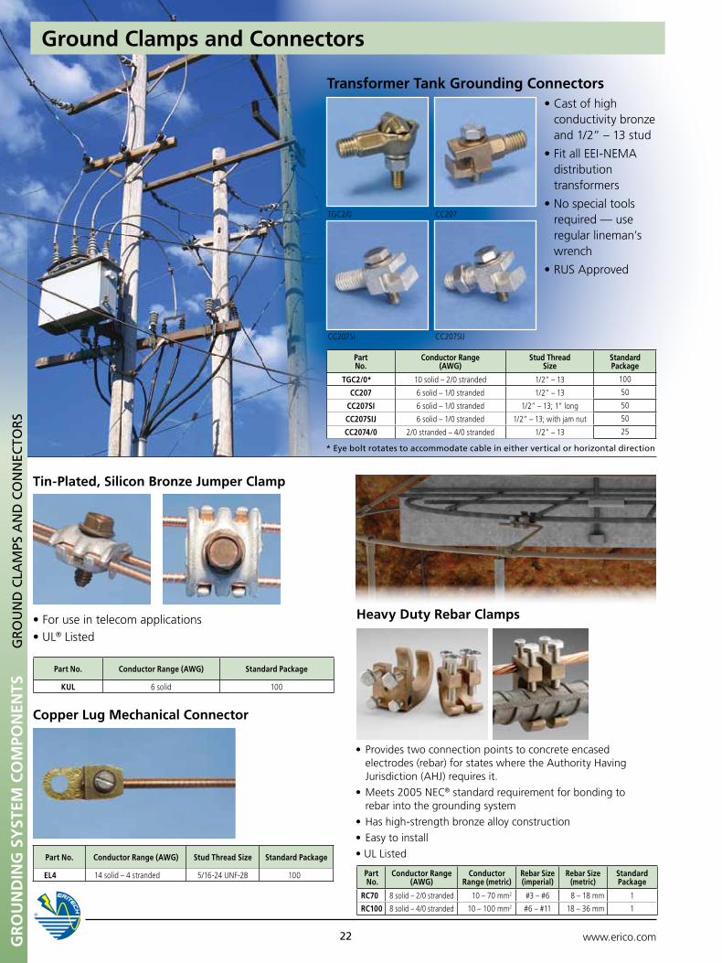
•Castofhighconductivity bronze and 1/2” – 13 stud
•FitallEEI-NEMAdistribution transformers
•Nospecialtoolsrequired — use regular lineman’s wrench
•RUSApproved
* Eye bolt rotates to accommodate cable in either vertical or horizontal direction
Transformer Tank Grounding Connectors
Part No.
Conductor Range (AWG)
Stud Thread Size
Standard Package
TGC2/0* 10 solid – 2/0 stranded 1/2” – 13 100
CC207 6 solid – 1/0 stranded 1/2” – 13 50
CC207SI 6 solid – 1/0 stranded 1/2” – 13; 1” long 50
CC207SIJ 6 solid – 1/0 stranded 1/2” – 13; with jam nut 50
CC2074/0 2/0 stranded – 4/0 stranded 1/2” – 13 25
GR
Ou
ND
ING
SY
STEM
CO
MPO
NEN
TSG
RO
un
D C
LAM
pS A
nD
CO
nn
ECTO
RS
Ground Clamps and Connectors
TGC2/0
CC207SI
CC207
CC207SIJ
Gr
ou
nd
inG
SY
STEM
Co
MPo
nEn
TS
www.erico.com 23
GR
Ou
nD
CLA
MpS
An
D C
On
nEC
TOR
S
Intersystem Bonding Termination Bar (IBTB)
Part No. Conductor Range Standard Package
IBTB (5) 14 Solid - 6 Stranded; (1) 6 Solid - 2 Stranded; (5) 1.5 - 25mm2; (1) 16 - 35 mmm2 10
•Interconnectsandterminatesgroundingconductorsfrom electrical power service, telephone, CATV, radio and TV antennas
•Idealforresidentialandsmallcommercialapplications
•Meetsrequirementsof2008NECArticle250.94
•cULus® Listed
Part No. Description Conductor Range (AWG)
EL6CS Tinned Bronze Lug with #10 Hardware #14 Sol - #6 Str
EL6CS8 Tinned Bronze Lug with #8 Hardware #14 Sol - #6 Str
EL6CSNH Tinned Bronze Lug without Hardware #14 Sol - #6 Str
EL6CSDB Direct Burial - Tinned Bronze Lug with #10 Hardware #14 Sol - #6 Str
EL6CSDB8 Direct Burial - Tinned Bronze Lug with #8 Hardware #14 Sol - #6 Str
EL6CSDBNH Direct Burial - Tinned Bronze Lug without Hardware #14 Sol - #6 Str
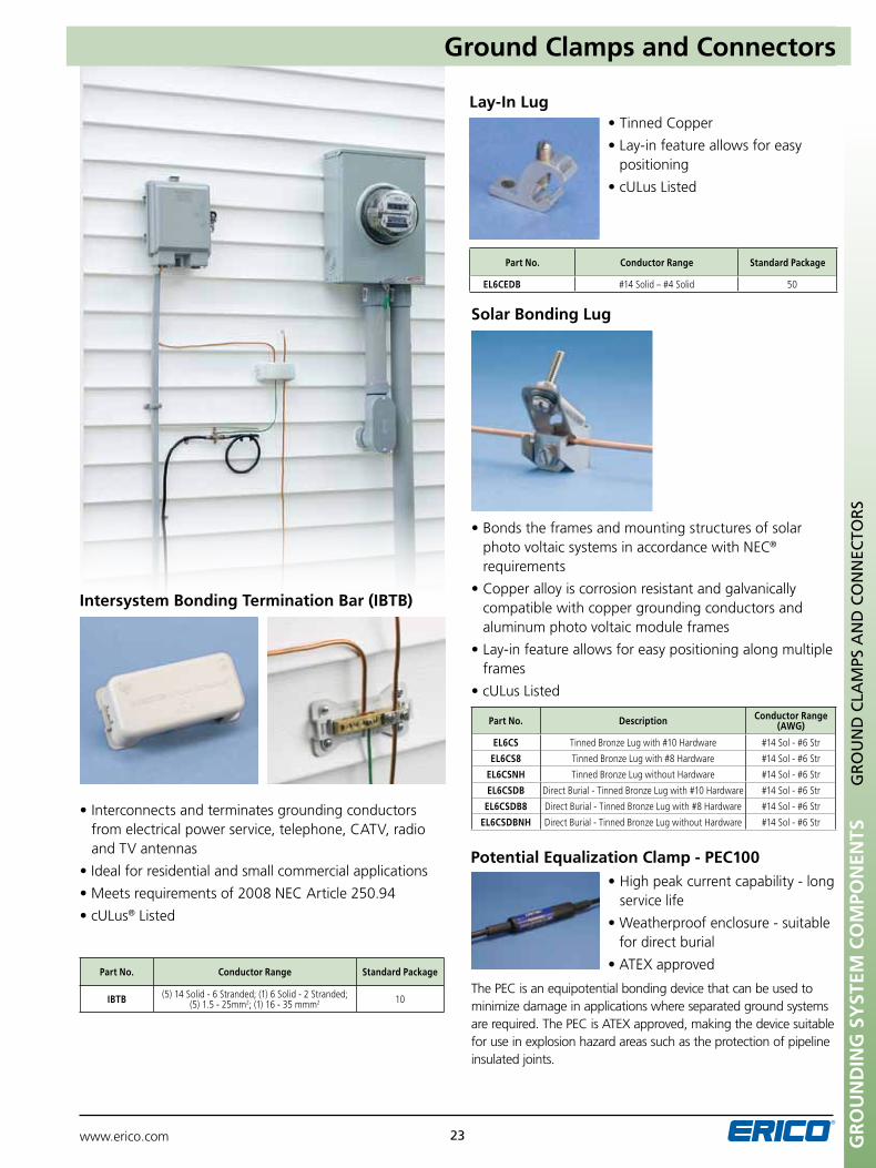
•Bondstheframesandmountingstructuresofsolarphoto voltaic systems in accordance with NEC® requirements
•Copperalloyiscorrosionresistantandgalvanicallycompatible with copper grounding conductors and aluminum photo voltaic module frames
•Lay-infeatureallowsforeasypositioningalongmultipleframes
•cULusListed
Solar Bonding Lug
Lay-In Lug
Potential Equalization Clamp - PEC100
•TinnedCopper
•Lay-infeatureallowsforeasypositioning
•cULusListed
•Highpeakcurrentcapability-longservice life
•Weatherproofenclosure-suitablefor direct burial
•ATEXapproved
Part No. Conductor Range Standard Package
EL6CEDB #14 Solid – #4 Solid 50
Ground Clamps and Connectors
The PEC is an equipotential bonding device that can be used to minimize damage in applications where separated ground systems arerequired.ThePECisATEXapproved,makingthedevicesuitablefor use in explosion hazard areas such as the protection of pipeline insulated joints.
Gr
ou
nd
inG
SY
STEM
Co
MPo
nEn
TS
www.erico.com24
CH
EMIC
AL
GR
Ou
nD
ELE
CTR
OD
ES
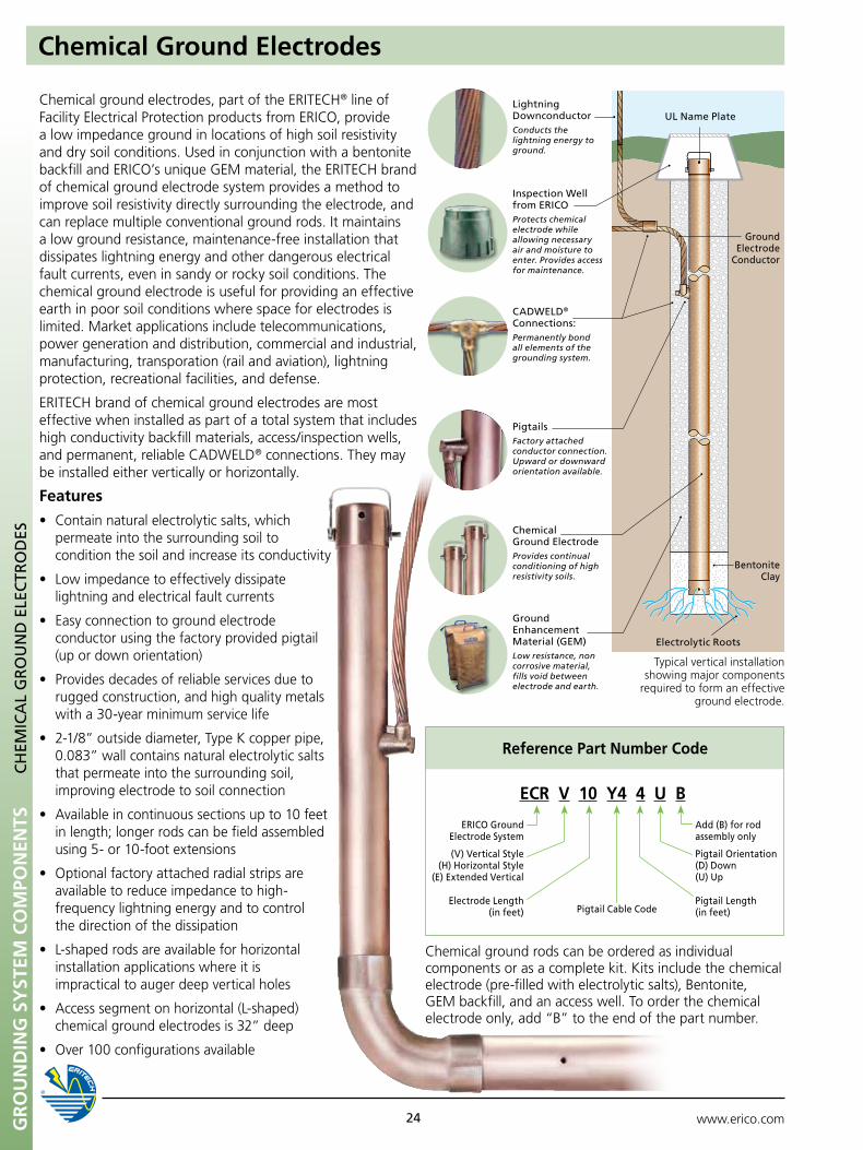
Chemical Ground Electrodes
Lightning DownconductorConducts the lightning energy to ground.
Inspection Well from ERICOProtects chemical electrode while allowing necessary air and moisture to enter. Provides access for maintenance.
CADWELD® Connections:Permanently bond all elements of the grounding system.
pigtailsFactory attached conductor connection. Upward or downward orientation available.
Chemical Ground ElectrodeProvides continual conditioning of high resistivity soils.
Ground Enhancement Material (GEM)Low resistance, non corrosive material, fills void between electrode and earth.
Electrolytic Roots
Bentonite Clay
Ground Electrode
Conductor
uL name plate
Typical vertical installation showing major components
required to form an effective ground electrode.
Reference Part Number Code
ECR V 10 Y4 4 u B
pigtail Length (in feet)
ERICO Ground Electrode System
pigtail Orientation(D) Down(u) up
Add (B) for rod assembly only
pigtail Cable CodeElectrode Length
(in feet)
(V) Vertical Style(H) Horizontal Style
(E) Extended Vertical
Chemical ground rods can be ordered as individual components or as a complete kit. Kits include the chemical electrode (pre-filled with electrolytic salts), Bentonite, GEM backfill, and an access well. To order the chemical electrode only, add “B” to the end of the part number.
Chemical ground electrodes, part of the ERITECH® line of Facility Electrical Protection products from ERICO, provide a low impedance ground in locations of high soil resistivity and dry soil conditions. Used in conjunction with a bentonite backfill and ERICO’s unique GEM material, the ERITECH brand of chemical ground electrode system provides a method to improve soil resistivity directly surrounding the electrode, and can replace multiple conventional ground rods. It maintains a low ground resistance, maintenance-free installation that dissipates lightning energy and other dangerous electrical fault currents, even in sandy or rocky soil conditions. The chemical ground electrode is useful for providing an effective earth in poor soil conditions where space for electrodes is limited. Market applications include telecommunications, power generation and distribution, commercial and industrial, manufacturing, transporation (rail and aviation), lightning protection, recreational facilities, and defense.
ERITECH brand of chemical ground electrodes are most effective when installed as part of a total system that includes high conductivity backfill materials, access/inspection wells, and permanent, reliable CADWELD® connections. They may be installed either vertically or horizontally.
Features
• Containnaturalelectrolyticsalts,which permeate into the surrounding soil to condition the soil and increase its conductivity
• Lowimpedancetoeffectivelydissipate lightning and electrical fault currents
• Easyconnectiontogroundelectrode conductor using the factory provided pigtail (up or down orientation)
• Providesdecadesofreliableservicesdueto rugged construction, and high quality metals with a 30-year minimum service life
• 2-1/8”outsidediameter,TypeKcopperpipe, 0.083” wall contains natural electrolytic salts that permeate into the surrounding soil, improving electrode to soil connection
• Availableincontinuoussectionsupto10feet in length; longer rods can be field assembled using 5- or 10-foot extensions
• Optionalfactoryattachedradialstripsare available to reduce impedance to high-
frequency lightning energy and to control the direction of the dissipation
• L-shapedrodsareavailableforhorizontal installation applications where it is
impractical to auger deep vertical holes
• Accesssegmentonhorizontal(L-shaped) chemical ground electrodes is 32” deep
• Over100configurationsavailable
Gr
ou
nd
inG
SY
STEM
Co
MPo
nEn
TS
www.erico.com 25
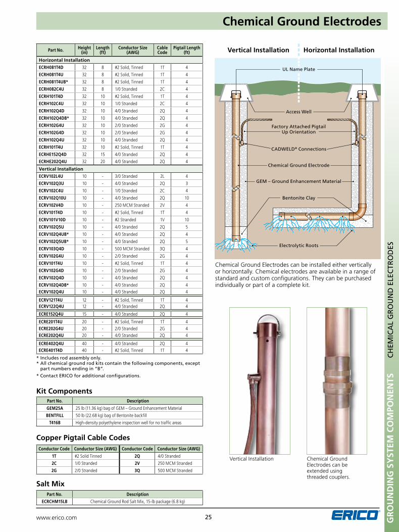
Vertical Installation Horizontal Installation
uL name plate
Electrolytic Roots
GEM – Ground Enhancement Material
CADWELD® Connections
Access Well
Bentonite Clay
Chemical Ground Electrode
Factory Attached pigtail up Orientation
Chemical Ground Electrodes can be installed either vertically or horizontally. Chemical electrodes are available in a range of standard and custom configurations. They can be purchased individually or part of a complete kit.
* Includes rod assembly only. * All chemical ground rod kits contain the following components, except
part numbers ending in “B”.
* Contact ERICO for additional configurations.
Chemical Ground Electrodes can be extended using threaded couplers.
Vertical Installation
Part No. Height (in)
Length (ft)
Conductor Size (AWG)
Cable Code
Pigtail Length (ft)
Horizontal Installation
ECRH081T4D 32 8 #2 Solid, Tinned 1T 4
ECRH081T4u 32 8 #2 Solid, Tinned 1T 4
ECRH081T4uB* 32 8 #2 Solid, Tinned 1T 4
ECRH082C4u 32 8 1/0 Stranded 2C 4
ECRH101T4D 32 10 #2 Solid, Tinned 1T 4
ECRH102C4u 32 10 1/0 Stranded 2C 4
ECRH102Q4D 32 10 4/0 Stranded 2Q 4
ECRH102Q4DB* 32 10 4/0 Stranded 2Q 4
ECRH102G4u 32 10 2/0 Stranded 2G 4
ECRH102G4D 32 10 2/0 Stranded 2G 4
ECRH102Q4u 32 10 4/0 Stranded 2Q 4
ECRH101T4u 32 10 #2 Solid, Tinned 1T 4
ECRHE152Q4D 32 15 4/0 Stranded 2Q 4
ECRHE202Q4u 32 20 4/0 Stranded 2Q 4
Vertical Installation
ECRV102L4u 10 - 3/0 Stranded 2L 4
ECRV102Q3u 10 - 4/0 Stranded 2Q 3
ECRV102C4u 10 - 1/0 Stranded 2C 4
ECRV102Q10u 10 - 4/0 Stranded 2Q 10
ECRV102V4D 10 - 250 MCM Stranded 2V 4
ECRV101T4D 10 - #2 Solid, Tinned 1T 4
ECRV101V10D 10 - #2 Stranded 1V 10
ECRV102Q5u 10 - 4/0 Stranded 2Q 5
ECRV102Q4uB* 10 - 4/0 Stranded 2Q 4
ECRV102Q5uB* 10 - 4/0 Stranded 2Q 5
ECRV103Q4D 10 - 500 MCM Stranded 3Q 4
ECRV102G4u 10 - 2/0 Stranded 2G 4
ECRV101T4u 10 - #2 Solid, Tinned 1T 4
ECRV102G4D 10 - 2/0 Stranded 2G 4
ECRV102Q4D 10 - 4/0 Stranded 2Q 4
ECRV102Q4DB* 10 - 4/0 Stranded 2Q 4ECRV102Q4u 10 - 4/0 Stranded 2Q 4
ECRV121T4u 12 - #2 Solid, Tinned 1T 4ECRV122Q4u 12 - 4/0 Stranded 2Q 4
ECRE152Q4u 15 - 4/0 Stranded 2Q 4
ECRE201T4u 20 - #2 Solid, Tinned 1T 4ECRE202G4u 20 - 2/0 Stranded 2G 4ECRE202Q4u 20 - 4/0 Stranded 2Q 4
ECRE402Q4u 40 - 4/0 Stranded 2Q 4ECRE401T4D 40 - #2 Solid, Tinned 1T 4
Part No. Description
GEM25A 25 lb (11.36 kg) bag of GEM – Ground Enhancement Material
BENTFILL 50 lb (22.68 kg) bag of Bentonite backfill
T416B High-density polyethylene inspection well for no traffic areas
Kit Components
Conductor Code Conductor Size (AWG) Conductor Code Conductor Size (AWG)
1T #2 Solid Tinned 2Q 4/0 Stranded
2C 1/0 Stranded 2V 250 MCM Stranded
2G 2/0 Stranded 3Q 500 MCM Stranded
Copper Pigtail Cable Codes
Part No. Description
ECRCHM15LB Chemical Ground Rod Salt Mix, 15-lb package (6.8 kg)
Salt Mix
CH
EMIC
AL
GR
Ou
nD
ELE
CTR
OD
ES
Chemical Ground Electrodes
www.erico.com26
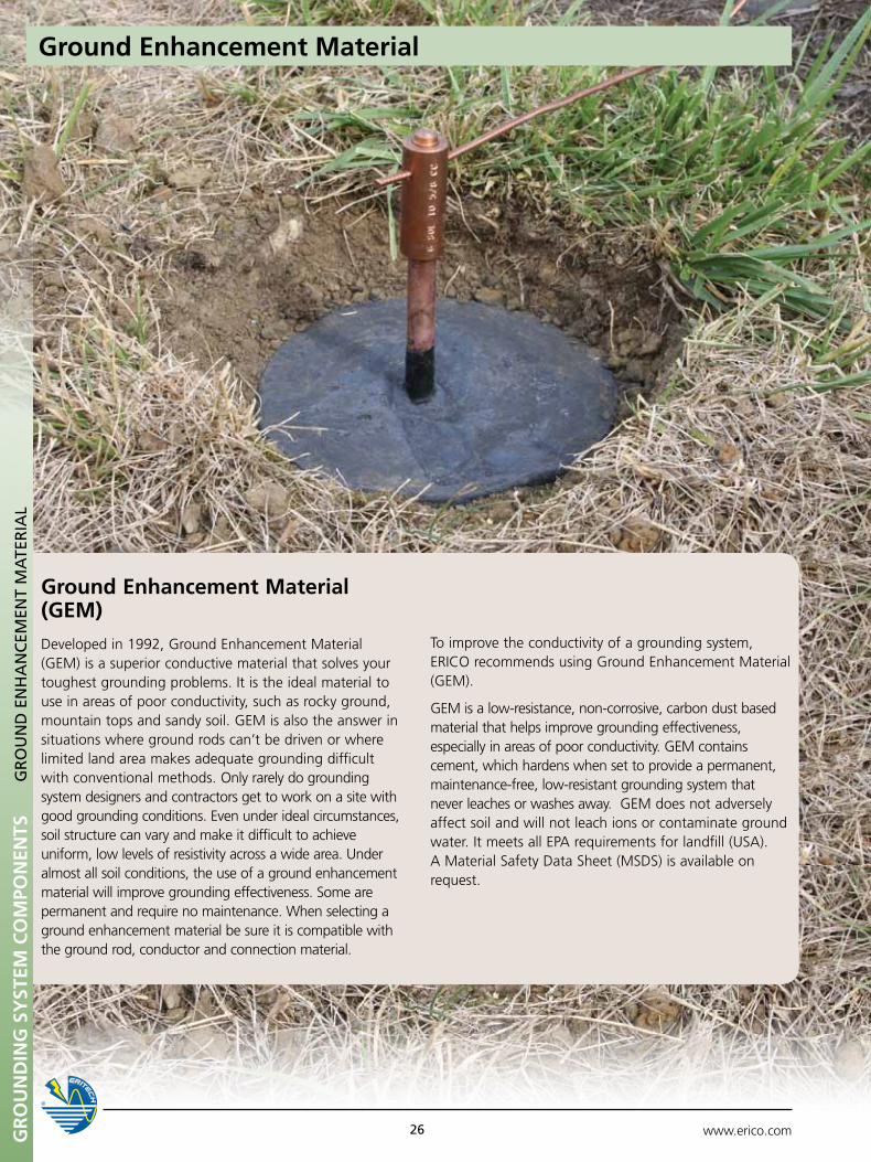
Ground Enhancement Material (GEM)
Developed in 1992, Ground Enhancement Material (GEM) is a superior conductive material that solves your toughest grounding problems. It is the ideal material to use in areas of poor conductivity, such as rocky ground, mountain tops and sandy soil. GEM is also the answer in situations where ground rods can’t be driven or where limited land area makes adequate grounding difficult with conventional methods. Only rarely do grounding system designers and contractors get to work on a site with good grounding conditions. Even under ideal circumstances, soil structure can vary and make it difficult to achieve uniform, low levels of resistivity across a wide area. Under almost all soil conditions, the use of a ground enhancement material will improve grounding effectiveness. Some are permanent and require no maintenance. When selecting a ground enhancement material be sure it is compatible with the ground rod, conductor and connection material.
GR
Ou
ND
ING
SY
STEM
CO
MPO
NEN
TSG
RO
un
D E
nH
An
CEM
EnT
MA
TER
IAL
Ground Enhancement Material
To improve the conductivity of a grounding system, ERICO recommends using Ground Enhancement Material (GEM).
GEM is a low-resistance, non-corrosive, carbon dust based material that helps improve grounding effectiveness, especially in areas of poor conductivity. GEM contains cement, which hardens when set to provide a permanent, maintenance-free, low-resistant grounding system that never leaches or washes away. GEM does not adversely affect soil and will not leach ions or contaminate ground water. It meets all EPA requirements for landfill (USA). A Material Safety Data Sheet (MSDS) is available on request.
www.erico.com 27
Ground Enhancement Material
GR
Ou
ND
ING
SY
STEM
CO
MPO
NEN
TSG
RO
un
D E
nH
An
CEM
EnT
MA
TER
IAL
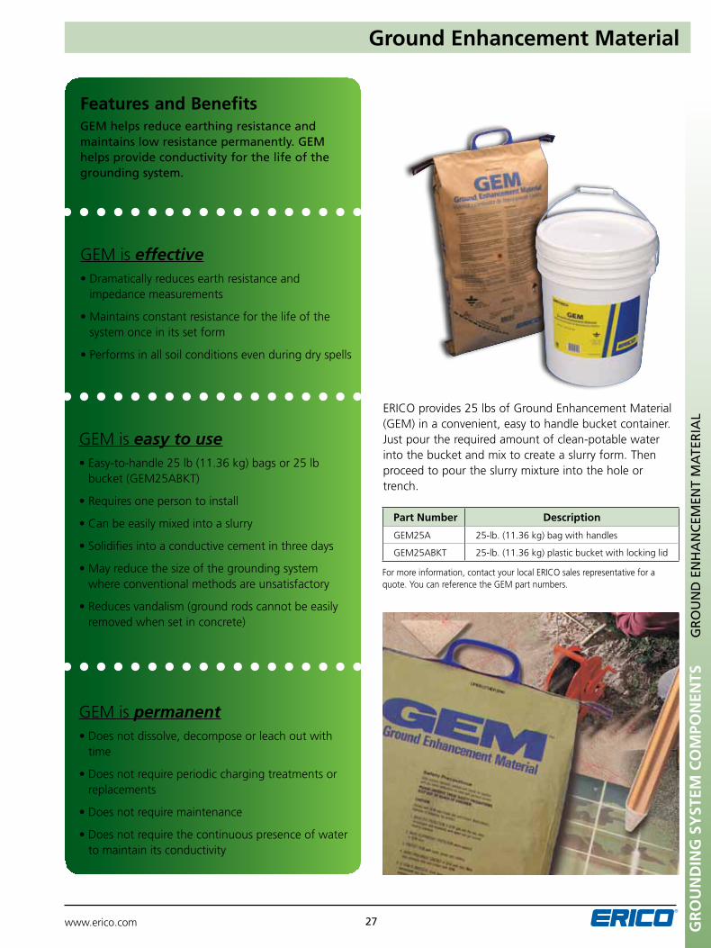
For more information, contact your local ERICO sales representative for a quote. You can reference the GEM part numbers.
Part Number Description
GEM25A 25-lb. (11.36 kg) bag with handles
GEM25ABKT 25-lb. (11.36 kg) plastic bucket with locking lid
Features and BenefitsGEM helps reduce earthing resistance and maintains low resistance permanently. GEM helps provide conductivity for the life of the grounding system.
ERICO provides 25 lbs of Ground Enhancement Material (GEM) in a convenient, easy to handle bucket container. Just pour the required amount of clean-potable water into the bucket and mix to create a slurry form. Then proceed to pour the slurry mixture into the hole or trench.
GEM is effective•Dramaticallyreducesearthresistanceand
impedance measurements
•Maintainsconstantresistanceforthelifeofthe system once in its set form
•Performsinallsoilconditionsevenduringdryspells
GEM is permanent•Doesnotdissolve,decomposeorleachoutwith
time
•Doesnotrequireperiodicchargingtreatmentsorreplacements
•Doesnotrequiremaintenance
•Doesnotrequirethecontinuouspresenceofwater to maintain its conductivity
GEM is easy to use•Easy-to-handle25lb(11.36kg)bagsor25lb
bucket (GEM25ABKT)
•Requiresonepersontoinstall
•Canbeeasilymixedintoaslurry
•Solidifiesintoaconductivecementinthreedays
•Mayreducethesizeofthegroundingsystem where conventional methods are unsatisfactory
•Reducesvandalism(groundrodscannotbeeasilyremoved when set in concrete)
Gr
ou
nd
inG
SY
STEM
Co
MPo
nEn
TS
www.erico.com28
GR
Ou
nD
En
HA
nC
EMEn
T M
ATE
RIA
L
Ground Enhancement Material
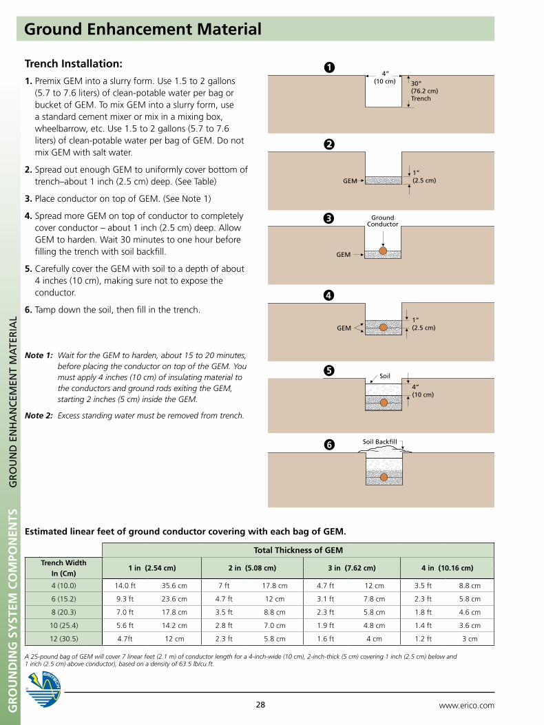
1. Premix GEM into a slurry form. Use 1.5 to 2 gallons (5.7 to 7.6 liters) of clean-potable water per bag or bucket of GEM. To mix GEM into a slurry form, use a standard cement mixer or mix in a mixing box, wheelbarrow, etc. Use 1.5 to 2 gallons (5.7 to 7.6 liters) of clean-potable water per bag of GEM. Do not mix GEM with salt water.
2. Spread out enough GEM to uniformly cover bottom of trench–about 1 inch (2.5 cm) deep. (See Table)
3. Place conductor on top of GEM. (See Note 1)
4. Spread more GEM on top of conductor to completely cover conductor – about 1 inch (2.5 cm) deep. Allow GEM to harden. Wait 30 minutes to one hour before filling the trench with soil backfill.
5. Carefully cover the GEM with soil to a depth of about 4 inches (10 cm), making sure not to expose the conductor.
6. Tamp down the soil, then fill in the trench.
Note 1: Wait for the GEM to harden, about 15 to 20 minutes, before placing the conductor on top of the GEM. You must apply 4 inches (10 cm) of insulating material to the conductors and ground rods exiting the GEM, starting 2 inches (5 cm) inside the GEM.
Note 2: Excess standing water must be removed from trench.
Trench Installation:
1” (2.5 cm)GEM
4” (10 cm)
Soil
Soil Backfill
GEM
Ground Conductor
GEM1” (2.5 cm)
30” (76.2 cm)Trench
4” (10 cm)
Estimated linear feet of ground conductor covering with each bag of GEM.
A 25-pound bag of GEM will cover 7 linear feet (2.1 m) of conductor length for a 4-inch-wide (10 cm), 2-inch-thick (5 cm) covering 1 inch (2.5 cm) below and 1 inch (2.5 cm) above conductor), based on a density of 63.5 lb/cu.ft.
Total Thickness of GEM
Trench Width1 in (2.54 cm) 2 in (5.08 cm) 3 in (7.62 cm) 4 in (10.16 cm)
In (Cm)
4 (10.0) 14.0 ft 35.6 cm 7 ft 17.8 cm 4.7 ft 12 cm 3.5 ft 8.8 cm
6 (15.2) 9.3 ft 23.6 cm 4.7 ft 12 cm 3.1 ft 7.8 cm 2.3 ft 5.8 cm
8 (20.3) 7.0 ft 17.8 cm 3.5 ft 8.8 cm 2.3 ft 5.8 cm 1.8 ft 4.6 cm
10 (25.4) 5.6 ft 14.2 cm 2.8 ft 7.0 cm 1.9 ft 4.8 cm 1.4 ft 3.6 cm
12 (30.5) 4.7ft 12 cm 2.3 ft 5.8 cm 1.6 ft 4 cm 1.2 ft 3 cm
Gr
ou
nd
inG
SY
STEM
Co
MPo
nEn
TS
www.erico.com 29
GR
Ou
nD
En
HA
nC
EMEn
T M
ATE
RIA
L
Ground Enhancement Material
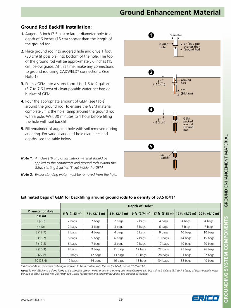
Ground Rod Backfill Installation:
* 8-foot (2.44 m) minimum rod length required to be in contact with the soil (or GEM), per NEC® 250-83-C.
Note: To mix GEM into a slurry form, use a standard cement mixer or mix in a mixing box, wheelbarrow, etc. Use 1.5 to 2 gallons (5.7 to 7.6 liters) of clean-potable water per bag of GEM. Do not mix GEM with salt water. For storage and safety precautions, see product packaging.
Estimated bags of GEM for backfilling around ground rods to a density of 63.5 lb/ft 3
1. Auger a 3-inch (7.5 cm) or larger diameter hole to a depth of 6 inches (15 cm) shorter than the length of the ground rod.
2. Place ground rod into augered hole and drive 1 foot (30 cm) (if possible) into bottom of the hole. The top of the ground rod will be approximately 6 inches (15 cm) below grade. At this time, make any connections to ground rod using CADWELD® connections. (See Note 1)
3. Premix GEM into a slurry form. Use 1.5 to 2 gallons (5.7 to 7.6 liters) of clean-potable water per bag or bucket of GEM.
4. Pour the appropriate amount of GEM (see table) around the ground rod. To ensure the GEM material completely fills the hole, tamp around the ground rod with a pole. Wait 30 minutes to 1 hour before filling the hole with soil backfill.
5. Fill remainder of augered hole with soil removed during augering. For various augered-hole diameters and depths, see the table below.
Note 1: 4 inches (10 cm) of insulating material should be applied to the conductors and ground rods exiting the GEM, starting 2 inches (5 cm) inside the GEM.
Note 2: Excess standing water must be removed from the hole.
6” (15.2 cm)
GEM packed around Ground Rod
Soil Backfill
Auger Hole
Diameter
6” (15.2 cm) shorter than Ground Rod
6” (15.2 cm)
Ground Rod
12”(30.4 cm)
Depth of Hole*
Diameter of Hole6 ft (1.83 m) 7 ft (2.13 m) 8 ft (2.44 m) 9 ft (2.74 m) 17 ft (5.18 m) 19 ft (5.79 m) 20 ft (6.10 m)
In (Cm)
3 (7.6) 2 bags 2 bags 2 bags 2 bags 4 bags 4 bags 4 bags
4 (10) 2 bags 3 bags 3 bags 3 bags 6 bags 7 bags 7 bags
5 (12.7) 3 bags 4 bags 4 bags 5 bags 9 bags 10 bags 10 bags
6 (15.2) 5 bags 5 bags 6 bags 7 bags 13 bags 14 bags 15 bags
7 (17.8) 6 bags 7 bags 8 bags 9 bags 17 bags 19 bags 20 bags
8 (20.3) 8 bags 9 bags 11 bags 12 bags 22 bags 25 bags 26 bags
9 (22.8) 10 bags 12 bags 13 bags 15 bags 28 bags 31 bags 32 bags
10 (25.4) 12 bags 14 bags 16 bags 18 bags 34 bags 38 bags 40 bags
www.erico.com30GR
Ou
ND
ING
SY
STEM
CO
MPO
NEN
TS
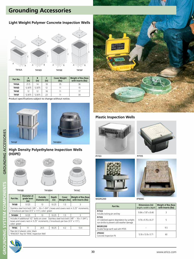
Light Weight Polymer Concrete Inspection Wells
T416DT416A
AA
C CC
C
BBB BA A
T416E T416F
Part No. A (in)
B (in)
C (in)
Cover Weight (lbs)
Weight of Box Base with Inserts (lbs)
T416A 21.5 14 18 35 36
T416D 12.875 12.875 12 11 15
T416E 12 12 18 11 17
T416F 12.875 12.875 23 11 30
Plastic Inspection Wells
pIT03 pIT05
Ip900CWGRS200
Part No. Dimensions (in)length x width x depth
Weight of Box Base with Inserts (lbs)
PIT03Includes locking pin and key 9.84 x 7.87 x 8.46 3
PIT05UV-stabilized against degredation by sunlight; non-brittle to prevent cold weather damage
9.76 x 9.76 x 8.27 5
WGRS200Double flange earth seal with PIT05 – 9.5
IP900CConcrete Inspection Pit 12.8 x 12.8 x 5.71 60
GROunDERICO
GROunDERICO
T416B T416BH T416C
Part No.Diameter at grade level
(in)
Outside Diameter (in)
Depth (in)
Cover Weight (lbs)
Weight of Box Base with Inserts (lbs)
T416B 9.125 13 10.25 1.5 3
Stainless steel lock bolt ( 3/8” – 16 x 1-3/4”); boxes and covers nest in 3.25” increments; 2 knockouts per box (3.5” x 1.5”); color: green
T416BH 9.125 13 10.25 1.5 3Includes 4 additional 1/2” bolts on cover. Stainless steel lock bolt ( 3/8” – 16 x 1-3/4”); boxes and covers nest in 3.25” increments; 2 knockouts per box (3.5” x 1.5”); color: green
T416C 11 24.5 18.25 4.2 13.4Pipe slot (2 places); color: blackT416CKEY: Key for T416C Inspection Well
GR
Ou
nD
InG
AC
CES
SOR
IES
Grounding Accessories
High Density Polyethylene Inspection Wells (HDPE)
product specifications subject to change without notice.
T416F T416BH
Gr
ou
nd
inG
SY
STEM
Co
MPo
nEn
TS
www.erico.com 31
GR
Ou
nD
pLA
TES
Ground Plates
Part Number: GPE C E A H 024 1L 024 (T)
pigtail Cable Type (ERICO Cable Code)
Ground plate Electrode
pigtail Length (inches)
T = Tinned
plate Thickness Code (Stock Tolerance)
pigtail Connection Type
Material
plate Length Code (inches) (3 digits required)
Example: GPECEAH0241L024
plate Width Code
Copper Ground Plates with Terminated, Welded Pigtails
plate Thickness
plate Length
plate Width
pigtail Length
pigtail Cable Type
pigtail Connection
Type
Terminated Pigtails
plate Length
plate Width
pigtail Length
Through Pigtail
pigtail Cable Type
pigtail Connection
Type
Part No. Thickness (in)
Width (in)
Length (in)
Cable Code Cable Size Pigtail
Length (in)
GPECEAH0241L024 1/32 12 24 1L #4 Stranded 24
GPECEAH0241T024 1/32 12 24 1T #2 Solid 24
GPECEAH0242Q024 1/32 12 24 2Q 4/0 Stranded 24
GPECEAJ0181G024 1/32 18 18 1G #6 Solid 24
GPECEAJ0182Q024 1/32 18 18 2Q 4/0 Stranded 24
GPECEAJ0241G024 1/32 18 24 1G #6 Solid 24
GPECEAK0241G024 1/32 24 24 1G #6 Solid 24
GPECEAK0241H024 1/32 24 24 1H #6 Stranded 24
GPECEAK0241T024 1/32 24 24 1T #2 Solid 24
GPECEAK0241V024 1/32 24 24 1V #2 Stranded 24
GPECEAK0241Y024 1/32 24 24 1Y #1 Stranded 24
GPECEAK0242G024 1/32 24 24 2G 2/0 Stranded 24
GPECEAK0242Q024 1/32 24 24 2Q 4/0 Stranded 24
GPECEAK0242V024 1/32 24 24 2V 250 MCM Stranded 24
GPECEAM0362Q024 1/32 36 36 2Q 4/0 Stranded 24GPECEAP0481H024 1/32 48 48 1H #6 Stranded 24
GPECEBH0121V024 1/16 12 12 1V #2 Stranded 24GPECEBH0122G024 1/16 12 12 2G 2/0 Stranded 24
GPECEBH0241K024 1/16 12 24 1K #4 Solid 24
GPECEBH0242G024 1/16 12 24 2G 2/0 Stranded 24GPECEBH0242L024 1/16 12 24 2L 3/0 Stranded 24
GPECEEK0242Q060 1/4 24 24 2Q 4/0 Stranded 60GPECEEK0361T024 1/4 24 36 1T #2 Solid 24
Material
A Steel (HRS M1020)
B Stainless Steel (SS304)
C Copper (C11000)
D Galvanized Steel
Pigtail Connection Type
C Continuous (2 x “L J” ERICO Conn.)
E End (“L J” ERICO Conn. Style)
N No Pigtail
Plate Width Code
A 1” J 18”
B 2” K 24”
C 3” L 30”
D 4” M 36”
E 5” N 42”
F 6” P 48”
G 9” Q 17”
H 12” R 10”
Plate Thickness Code
A 1/32” (Min. for Lightning – Cu)
B 1/16” (Min. for Power – Cu)
C 3/32”
D 1/8”
E 1/4” (Min. for Power – Stl.)
F 3/8”
G 1/2”
H 1/64” (26 Gauge)
J 3/16”
CADWELD Cable Codes – Bare, Solid Copper Conductor
2P 4/0 Solid 1X #1 Solid 1G #6 Solid
2K 3/0 Solid 1T #2 Solid 1D #8 Solid
2F 2/0 Solid 1P #3 Solid 1A #10 Solid
2B 1/0 Solid 1K #4 Solid
CADWELD® Cable Codes – Bare, Concentric Stranded Copper Conductor
2Q 4/0 Stranded 1Y #1 Stranded 1H #6 Stranded
2L 3/0 Stranded 1V #2 Stranded 1E #8 Stranded
2G 2/0 Stranded 1Q #3 Stranded 1B #10 Stranded
2C 1/0 Stranded 1L #4 Stranded
Contact ERICO for additional product configurations.
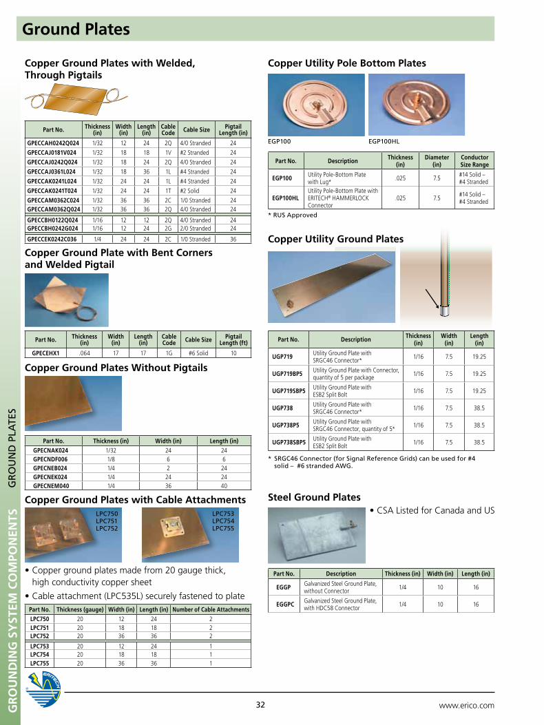
Gr
ou
nd
inG
SY
STEM
Co
MPo
nEn
TS
www.erico.com32
Copper Ground Plate with Bent Corners and Welded Pigtail
Copper Ground Plates Without Pigtails
* RuS Approved
Copper utility Pole Bottom Plates
EGp100 EGp100HL
Copper Ground Plates with Welded, Through Pigtails
Part No. Thickness (in)
Width (in)
Length (in)
Cable Code Cable Size Pigtail
Length (ft)
GPECEHX1 .064 17 17 1G #6 Solid 10
Part No. Thickness (in) Width (in) Length (in)GPECNAK024 1/32 24 24GPECNDF006 1/8 6 6GPECNEB024 1/4 2 24GPECNEK024 1/4 24 24GPECNEM040 1/4 36 40
Part No. Thickness (in)
Width (in)
Length (in)
Cable Code Cable Size Pigtail
Length (in)
GPECCAH0242Q024 1/32 12 24 2Q 4/0 Stranded 24
GPECCAJ0181V024 1/32 18 18 1V #2 Stranded 24
GPECCAJ0242Q024 1/32 18 24 2Q 4/0 Stranded 24
GPECCAJ0361L024 1/32 18 36 1L #4 Stranded 24
GPECCAK0241L024 1/32 24 24 1L #4 Stranded 24
GPECCAK0241T024 1/32 24 24 1T #2 Solid 24
GPECCAM0362C024 1/32 36 36 2C 1/0 Stranded 24GPECCAM0362Q024 1/32 36 36 2Q 4/0 Stranded 24
GPECCBH0122Q024 1/16 12 12 2Q 4/0 Stranded 24GPECCBH0242G024 1/16 12 24 2G 2/0 Stranded 24
GPECCEK0242C036 1/4 24 24 2C 1/0 Stranded 36
Copper Ground Plates with Cable Attachments
•Coppergroundplatesmadefrom20gaugethick, high conductivity copper sheet
•Cableattachment(LPC535L)securelyfastenedtoplate
•CSAListedforCanadaandUS
Part No. Thickness (gauge) Width (in) Length (in) Number of Cable AttachmentsLPC750 20 12 24 2LPC751 20 18 18 2LPC752 20 36 36 2
LPC753 20 12 24 1LPC754 20 18 18 1LPC755 20 36 36 1
Steel Ground Plates
Part No. Description Thickness (in) Width (in) Length (in)
EGGP Galvanized Steel Ground Plate, without Connector 1/4 10 16
EGGPC Galvanized Steel Ground Plate, with HDC58 Connector 1/4 10 16
GR
Ou
nD
pLA
TES
Ground Plates
* SRGC46 Connector (for Signal Reference Grids) can be used for #4 solid – #6 stranded AWG.
Copper utility Ground Plates
Part No. Description Thickness (in)
Width (in)
Length (in)
uGP719 Utility Ground Plate with SRGC46 Connector* 1/16 7.5 19.25
uGP719BP5 Utility Ground Plate with Connector, quantity of 5 per package 1/16 7.5 19.25
uGP719SBP5 Utility Ground Plate with ESB2 Split Bolt 1/16 7.5 19.25
uGP738 Utility Ground Plate with SRGC46 Connector* 1/16 7.5 38.5
uGP738P5 Utility Ground Plate with SRGC46 Connector, quantity of 5* 1/16 7.5 38.5
uGP738SBP5 Utility Ground Plate with ESB2 Split Bolt 1/16 7.5 38.5
Part No. Description Thickness (in)
Diameter (in)
Conductor Size Range
EGP100 Utility Pole-Bottom Plate with Lug* .025 7.5 #14 Solid –
#4 Stranded
EGP100HLUtility Pole-Bottom Plate with ERITECH® HAMMERLOCK Connector
.025 7.5 #14 Solid – #4 Stranded
LpC750 LpC751 LpC752
LpC753 LpC754 LpC755
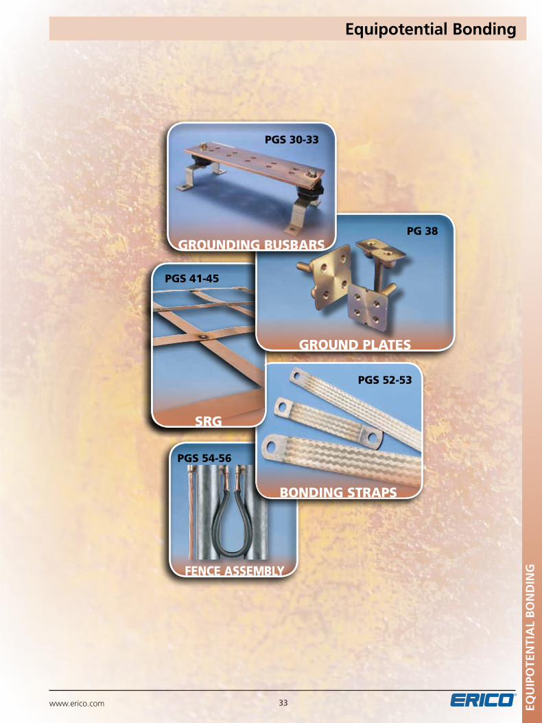
www.erico.com 33
fence assembly
pgs 52-53
pgs 54-56
bonding straps
ground plates
pg 38
pgs 41-45
EQu
IPO
TEN
TIA
L B
ON
DIN
G
Equipotential Bonding
grounding busbars
pgs 30-33
srg
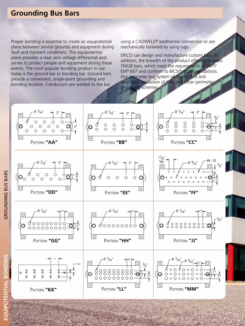
www.erico.com34
Grounding Bus Bars
PATTERN: "AA" PATTERN: "BB" PATTERN: "CC" PATTERN: "DD"
PATTERN: "EE" PATTERN: "FF" PATTERN: "GG" PATTERN: "HH"
PATTERN: "JJ" PATTERN: "LL" PATTERN: "MM" PATTERN: "NN"
2”
2”
2”
1”
2”
1”
Ø 7/ 16“ 2”
1”
2”#6 – 32
1”
1 1/ 8“Typ. Ø 9/ 32“ 3/ 4“
Ø 7/ 16“
Ø 7/ 16“ Ø 7/ 16“ Ø 7/ 16“
3/ 4“
Ø 7/ 16“ 1”Ø 7/ 16“ 1”
1”
1”Ø 7/ 16“ 1”Ø 7/ 16“
1”
Ø 7/ 16“
1”
3/ 4“ 1”
1”
Ø 5/ 16“
3/ 4“
Pattern “JJ”
PATTERN: "AA" PATTERN: "BB" PATTERN: "CC" PATTERN: "DD"
PATTERN: "EE" PATTERN: "FF" PATTERN: "GG" PATTERN: "HH"
PATTERN: "JJ" PATTERN: "LL" PATTERN: "MM" PATTERN: "NN"
2”
2”
2”
1”
2”
1”
Ø 7/ 16“ 2”
1”
2”#6 – 32
1”
1 1/ 8“Typ. Ø 9/ 32“ 3/ 4“
Ø 7/ 16“
Ø 7/ 16“ Ø 7/ 16“ Ø 7/ 16“
3/ 4“
Ø 7/ 16“ 1”Ø 7/ 16“ 1”
1”
1”Ø 7/ 16“ 1”Ø 7/ 16“
1”
Ø 7/ 16“
1”
3/ 4“ 1”
1”
Ø 5/ 16“
3/ 4“
Pattern “LL”
PATTERN: "AA" PATTERN: "BB" PATTERN: "CC" PATTERN: "DD"
PATTERN: "EE" PATTERN: "FF" PATTERN: "GG" PATTERN: "HH"
PATTERN: "JJ" PATTERN: "LL" PATTERN: "MM" PATTERN: "NN"
2”
2”
2”
1”
2”
1”
Ø 7/ 16“ 2”
1”
2”#6 – 32
1”
1 1/ 8“Typ. Ø 9/ 32“ 3/ 4“
Ø 7/ 16“
Ø 7/ 16“ Ø 7/ 16“ Ø 7/ 16“
3/ 4“
Ø 7/ 16“ 1”Ø 7/ 16“ 1”
1”
1”Ø 7/ 16“ 1”Ø 7/ 16“
1”
Ø 7/ 16“
1”
3/ 4“ 1”
1”
Ø 5/ 16“
3/ 4“
Pattern “MM”
PATTERN: "AA" PATTERN: "BB" PATTERN: "CC" PATTERN: "DD"
PATTERN: "EE" PATTERN: "FF" PATTERN: "GG" PATTERN: "HH"
PATTERN: "JJ" PATTERN: "LL" PATTERN: "MM" PATTERN: "NN"
2”
2”
2”
1”
2”
1”
Ø 7/ 16“ 2”
1”
2”#6 – 32
1”
1 1/ 8“Typ. Ø 9/ 32“ 3/ 4“
Ø 7/ 16“
Ø 7/ 16“ Ø 7/ 16“ Ø 7/ 16“
3/ 4“
Ø 7/ 16“ 1”Ø 7/ 16“ 1”
1”
1”Ø 7/ 16“ 1”Ø 7/ 16“
1”
Ø 7/ 16“
1”
3/ 4“ 1”
1”
Ø 5/ 16“
3/ 4“
Pattern “EE”PATTERN: "AA" PATTERN: "BB" PATTERN: "CC" PATTERN: "DD"
PATTERN: "EE" PATTERN: "FF" PATTERN: "GG" PATTERN: "HH"
PATTERN: "JJ" PATTERN: "LL" PATTERN: "MM" PATTERN: "NN"
2”
2”
2”
1”
2”
1”
Ø 7/ 16“ 2”
1”
2”#6 – 32
1”
1 1/ 8“Typ. Ø 9/ 32“ 3/ 4“
Ø 7/ 16“
Ø 7/ 16“ Ø 7/ 16“ Ø 7/ 16“
3/ 4“
Ø 7/ 16“ 1”Ø 7/ 16“ 1”
1”
1”Ø 7/ 16“ 1”Ø 7/ 16“
1”
Ø 7/ 16“
1”
3/ 4“ 1”
1”
Ø 5/ 16“
3/ 4“
Pattern “HH”
PATTERN: "AA" PATTERN: "BB" PATTERN: "CC" PATTERN: "DD"
PATTERN: "EE" PATTERN: "FF" PATTERN: "GG" PATTERN: "HH"
PATTERN: "JJ" PATTERN: "LL" PATTERN: "MM" PATTERN: "NN"
2”
2”
2”
1”
2”
1”
Ø 7/ 16“ 2”
1”
2”#6 – 32
1”
1 1/ 8“Typ. Ø 9/ 32“ 3/ 4“
Ø 7/ 16“
Ø 7/ 16“ Ø 7/ 16“ Ø 7/ 16“
3/ 4“
Ø 7/ 16“ 1”Ø 7/ 16“ 1”
1”
1”Ø 7/ 16“ 1”Ø 7/ 16“
1”
Ø 7/ 16“
1”
3/ 4“ 1”
1”
Ø 5/ 16“
3/ 4“
Pattern “FF”PATTERN: "AA" PATTERN: "BB" PATTERN: "CC" PATTERN: "DD"
PATTERN: "EE" PATTERN: "FF" PATTERN: "GG" PATTERN: "HH"
PATTERN: "JJ" PATTERN: "LL" PATTERN: "MM" PATTERN: "NN"
2”
2”
2”
1”
2”
1”
Ø 7/ 16“ 2”
1”
2”#6 – 32
1”
1 1/ 8“Typ. Ø 9/ 32“ 3/ 4“
Ø 7/ 16“
Ø 7/ 16“ Ø 7/ 16“ Ø 7/ 16“
3/ 4“
Ø 7/ 16“ 1”Ø 7/ 16“ 1”
1”
1”Ø 7/ 16“ 1”Ø 7/ 16“
1”
Ø 7/ 16“
1”
3/ 4“ 1”
1”
Ø 5/ 16“
3/ 4“
Pattern “GG”
PATTERN: "AA" PATTERN: "BB" PATTERN: "CC" PATTERN: "DD"
PATTERN: "EE" PATTERN: "FF" PATTERN: "GG" PATTERN: "HH"
PATTERN: "JJ" PATTERN: "LL" PATTERN: "MM" PATTERN: "NN"
2”
2”
2”
1”
2”
1”
Ø 7/ 16“ 2”
1”
2”#6 – 32
1”
1 1/ 8“Typ. Ø 9/ 32“ 3/ 4“
Ø 7/ 16“
Ø 7/ 16“ Ø 7/ 16“ Ø 7/ 16“
3/ 4“
Ø 7/ 16“ 1”Ø 7/ 16“ 1”
1”
1”Ø 7/ 16“ 1”Ø 7/ 16“
1”
Ø 7/ 16“
1”
3/ 4“ 1”
1”
Ø 5/ 16“
3/ 4“
Pattern “AA”
PATTERN: "AA" PATTERN: "BB" PATTERN: "CC" PATTERN: "DD"
PATTERN: "EE" PATTERN: "FF" PATTERN: "GG" PATTERN: "HH"
PATTERN: "JJ" PATTERN: "LL" PATTERN: "MM" PATTERN: "NN"
2”
2”
2”
1”
2”
1”
Ø 7/ 16“ 2”
1”
2”#6 – 32
1”
1 1/ 8“Typ. Ø 9/ 32“ 3/ 4“
Ø 7/ 16“
Ø 7/ 16“ Ø 7/ 16“ Ø 7/ 16“
3/ 4“
Ø 7/ 16“ 1”Ø 7/ 16“ 1”
1”
1”Ø 7/ 16“ 1”Ø 7/ 16“
1”
Ø 7/ 16“
1”
3/ 4“ 1”
1”
Ø 5/ 16“
3/ 4“
Pattern “DD”
PATTERN: "AA" PATTERN: "BB" PATTERN: "CC" PATTERN: "DD"
PATTERN: "EE" PATTERN: "FF" PATTERN: "GG" PATTERN: "HH"
PATTERN: "JJ" PATTERN: "LL" PATTERN: "MM" PATTERN: "NN"
2”
2”
2”
1”
2”
1”
Ø 7/ 16“ 2”
1”
2”#6 – 32
1”
1 1/ 8“Typ. Ø 9/ 32“ 3/ 4“
Ø 7/ 16“
Ø 7/ 16“ Ø 7/ 16“ Ø 7/ 16“
3/ 4“
Ø 7/ 16“ 1”Ø 7/ 16“ 1”
1”
1”Ø 7/ 16“ 1”Ø 7/ 16“
1”
Ø 7/ 16“
1”
3/ 4“ 1”
1”
Ø 5/ 16“
3/ 4“
Pattern “BB”PATTERN: "AA" PATTERN: "BB" PATTERN: "CC" PATTERN: "DD"
PATTERN: "EE" PATTERN: "FF" PATTERN: "GG" PATTERN: "HH"
PATTERN: "JJ" PATTERN: "LL" PATTERN: "MM" PATTERN: "NN"
2”
2”
2”
1”
2”
1”
Ø 7/ 16“ 2”
1”
2”#6 – 32
1”
1 1/ 8“Typ. Ø 9/ 32“ 3/ 4“
Ø 7/ 16“
Ø 7/ 16“ Ø 7/ 16“ Ø 7/ 16“
3/ 4“
Ø 7/ 16“ 1”Ø 7/ 16“ 1”
1”
1”Ø 7/ 16“ 1”Ø 7/ 16“
1”
Ø 7/ 16“
1”
3/ 4“ 1”
1”
Ø 5/ 16“
3/ 4“
Pattern “CC”
Pattern “KK”
3/4
7/8
2
3/4
1
Proper bonding is essential to create an equipotential plane between service grounds and equipment during fault and transient conditions. This equipotential plane provides a near zero voltage differential and serves to protect people and equipment during these events. The most popular bonding product in use today is the ground bar or bonding bar. Ground bars provide a convenient, single-point grounding and bonding location. Conductors are welded to the bar
using a CADWELD® exothermic connection or are mechanically fastened by using lugs.
ERICO can design and manufacture custom bars. In addition, the breadth of the product offering includes TMGB bars, which meet the requirements of TIA®/EIA® 607 and conform to BICSI® recommendations. Our perimeter bus system allows for fast and easy field installation of halo and other perimeter grounding schemes.
EQu
IPO
TEN
TIA
L B
ON
DIN
GG
RO
un
DIn
G B
uS
BA
RS
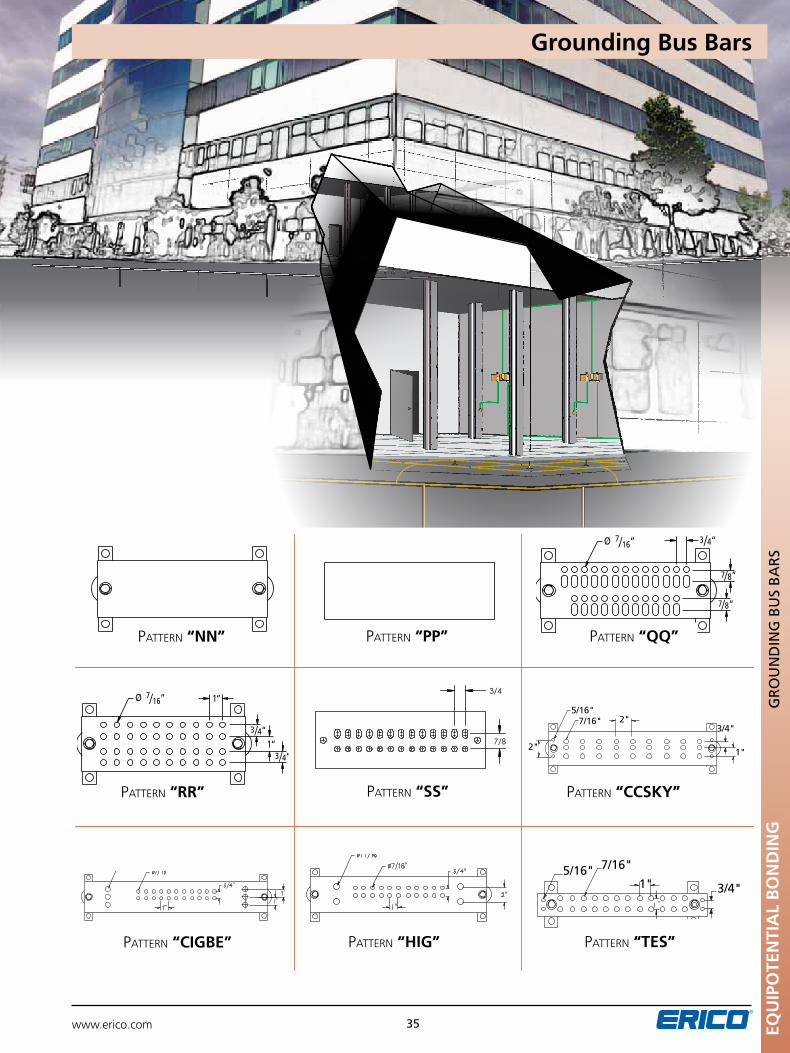
www.erico.com 35
PATTERN: "AA" PATTERN: "BB" PATTERN: "CC" PATTERN: "DD"
PATTERN: "EE" PATTERN: "FF" PATTERN: "GG" PATTERN: "HH"
PATTERN: "JJ" PATTERN: "LL" PATTERN: "MM" PATTERN: "NN"
2”
2”
2”
1”
2”
1”
Ø 7/ 16“ 2”
1”
2”#6 – 32
1”
1 1/ 8“Typ. Ø 9/ 32“ 3/ 4“
Ø 7/ 16“
Ø 7/ 16“ Ø 7/ 16“ Ø 7/ 16“
3/ 4“
Ø 7/ 16“ 1”Ø 7/ 16“ 1”
1”
1”Ø 7/ 16“ 1”Ø 7/ 16“
1”
Ø 7/ 16“
1”
3/ 4“ 1”
1”
Ø 5/ 16“
3/ 4“
Pattern “NN”
PATTERN: "PP" PATTERN: "QQ" PATTERN: "RR"
3 / 4“
3 / 4“
7/ 8“
Ø 7/ 16“ Ø 7/ 16“ 1“
1“7/ 8“ 3
/ 4“
Pattern “RR”
PATTERN: "PP" PATTERN: "QQ" PATTERN: "RR"
3 / 4“
3 / 4“
7/ 8“
Ø 7/ 16“ Ø 7/ 16“ 1“
1“7/ 8“ 3
/ 4“
Pattern “PP”
Pattern “TES”Pattern “CIGBE”
Pattern “CCSKY”Pattern “SS”
PATTERN: "PP" PATTERN: "QQ" PATTERN: "RR"
3 / 4“
3 / 4“
7/ 8“
Ø 7/ 16“ Ø 7/ 16“ 1“
1“7/ 8“ 3
/ 4“
Pattern “QQ”
Pattern “HIG”
3/4
7/8
2
3/4
1
Grounding Bus Bars
EQu
IPO
TEN
TIA
L B
ON
DIN
GG
RO
un
DIn
G B
uS
BA
RS
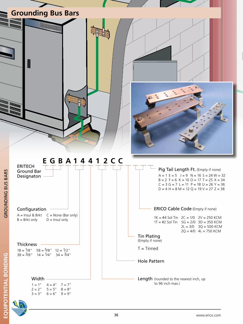
www.erico.com36EQu
IPO
TEN
TIA
L B
ON
DIN
GG
RO
un
DIn
G B
uS
BA
RS
Thickness18 = 1/8” 58 = 5/8” 12 = 1/2”38 = 3/8” 14 = 1/4” 34 = 3/4”
pig Tail Length Ft. (Empty if none)
A = 1 E = 5 J = 9 N = 16 S = 24 W = 32B=2 F=6 K=10O=17T=25X=34C = 3 G = 7 L = 11 P = 18 U = 26 Y = 36D = 4 H = 8 M = 12 Q = 19 V = 27 Z = 38
ConfigurationA=Insul&Brkt C=None(Baronly)B = Brkt only D = Insul only
Tin plating (Empty if none)
T = Tinned
ERICO Cable Code (Empty if none)
1K = #4 Sol Tin 2C = 1/0 2V = 250 KCM1T = #2 Sol Tin SG = 2/0 3D = 350 KCM 2L = 3/0 3Q = 500 KCM 2Q = 4/0 4L = 750 KCM
Hole pattern
Length (rounded to the nearest inch, up to 96 inch max.)
ERITECH Ground Bar Designaton
Width1 = 1” 4 = 4” 7 = 7”2 = 2” 5 = 5” 8 = 8” 3 = 3” 6 = 6” 9 = 9”
4 4E G B A 1 1 2 C C
Grounding Bus Bars
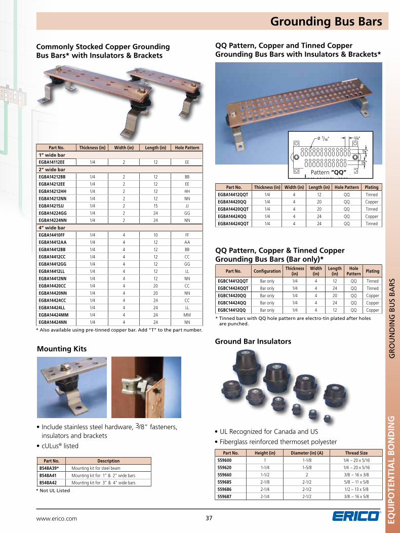
www.erico.com EQU
IPO
TEN
TIA
L B
ON
DIN
G
37
GR
Ou
nD
InG
Bu
S B
AR
S
Commonly Stocked Copper Grounding Bus Bars* with Insulators & Brackets
QQ Pattern, Copper and Tinned Copper Grounding Bus Bars with Insulators & Brackets*
* Tinned bars with QQ hole pattern are electro-tin plated after holes are punched.
* Also available using pre-tinned copper bar. Add “T” to the part number.
* not uL Listed
QQ Pattern, Copper & Tinned Copper Grounding Bus Bars (Bar only)*
PATTERN: "PP" PATTERN: "QQ" PATTERN: "RR"
3 / 4“
3 / 4“
7/ 8“
Ø 7/ 16“ Ø 7/ 16“ 1“
1“7/ 8“ 3
/ 4“
Part No. Thickness (in) Width (in) Length (in) Hole Pattern
1” wide bar
EGBA14112EE 1/4 2 12 EE
2” wide bar
EGBA14212BB 1/4 2 12 BB
EGBA14212EE 1/4 2 12 EE
EGBA14212HH 1/4 2 12 HH
EGBA14212NN 1/4 2 12 NN
EGBA14215JJ 1/4 2 15 JJ
EGBA14224GG 1/4 2 24 GG
EGBA14224NN 1/4 2 24 NN
4” wide bar
EGBA14410FF 1/4 4 10 FF
EGBA14412AA 1/4 4 12 AA
EGBA14412BB 1/4 4 12 BB
EGBA14412CC 1/4 4 12 CC
EGBA14412GG 1/4 4 12 GG
EGBA14412LL 1/4 4 12 LL
EGBA14412NN 1/4 4 12 NN
EGBA14420CC 1/4 4 20 CC
EGBA14420NN 1/4 4 20 NN
EGBA14424CC 1/4 4 24 CC
EGBA14424LL 1/4 4 24 LL
EGBA14424MM 1/4 4 24 MM
EGBA14424NN 1/4 4 24 NN
Part No. Thickness (in) Width (in) Length (in) Hole Pattern Plating
EGBA14412QQT 1/4 4 12 QQ Tinned
EGBA14420QQ 1/4 4 20 QQ Copper
EGBA14420QQT 1/4 4 20 QQ Tinned
EGBA14424QQ 1/4 4 24 QQ Copper
EGBA14424QQT 1/4 4 24 QQ Tinned
Part No. Configuration Thickness (in)
Width (in)
Length (in)
Hole Pattern Plating
EGBC14412QQT Bar only 1/4 4 12 QQ Tinned
EGBC14424QQT Bar only 1/4 4 24 QQ Tinned
EGBC14420QQ Bar only 1/4 4 20 QQ Copper
EGBC14424QQ Bar only 1/4 4 24 QQ Copper
EGBC14412QQ Bar only 1/4 4 12 QQ Copper
Mounting Kits
•Includestainlesssteelhardware,3/8” fasteners, insulators and brackets
•cULus® listed
Part No. Description
B548A39* Mounting kit for steel beam
B548A41 Mountingkitfor1”&2”widebars
B548A42 Mountingkitfor3”&4”widebars
Ground Bar Insulators
•ULRecognizedforCanadaandUS
•Fiberglassreinforcedthermosetpolyester
Part No. Height (in) Diameter (in) (A) Thread Size
559600 1 1-1/8 1/4 – 20 x 5/16
559620 1-1/4 1-5/8 1/4 – 20 x 5/16
559660 1-1/2 2 3/8 – 16 x 3/8
559685 2-1/8 2-1/2 5/8 – 11 x 5/8
559686 2-1/4 2-1/2 1/2 – 13 x 5/8
559687 2-1/4 2-1/2 3/8 – 16 x 5/8
Pattern “QQ”
Grounding Bus Bars
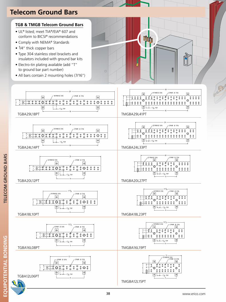
www.erico.com
15 PAIR12
Ø 5/16
9
5/85/8
41
3 PAIR Ø 7/16
19 PAIR Ø 5/16
9
5/85/8
41
3 PAIR Ø 7/16
27 PAIR20
Ø 5/16
9
5/85/8
41
3 PAIR Ø 7/16
23 PAIR Ø 5/16
9
5/85/8
4
1
3 PAIR Ø 7/16
41 PAIR
24
Ø 5/16
18
5/85/8
41
5 PAIR Ø 7/16
33 PAIR Ø 5/16
18
5/85/8
4
1
5 PAIR Ø 7/16
29
14 PAIR Ø 5/16
18
5/82 1
5 PAIR Ø 7/16
18 PAIR Ø 5/16
18
24
5/82 1
5 PAIR Ø 7/16
29
10 PAIR
20
Ø 5/16
9
5/82 1
3 PAIR Ø 7/16
12 PAIR Ø 5/16
9
5/82 1
3 PAIR Ø 7/16
6 PAIR Ø 5/16
9
5/82 1
3 PAIR Ø 7/16
8 PAIR Ø 5/16
9
5/82 1
3 PAIR Ø 7/16
1 1/ 8 TYP
1 1/ 8 TYP
1 1/ 8 TYP
1 1/ 8 TYP
1 1/ 8 TYP
1 1/ 8 TYP1 1/ 8 TYP
1 1/ 8 TYP
1 1/ 8 TYP
1 1/ 8 TYP
1 1/ 8 TYP
1 1/ 8 TYP
17 3/ 4
15 1/ 2
17 3/ 4
12
15 1/ 2
TGBA24L14PT TMGBA24L33PT
15 PAIR12
Ø 5/16
9
5/85/8
41
3 PAIR Ø 7/16
19 PAIR Ø 5/16
9
5/85/8
41
3 PAIR Ø 7/16
27 PAIR20
Ø 5/16
9
5/85/8
41
3 PAIR Ø 7/16
23 PAIR Ø 5/16
9
5/85/8
4
1
3 PAIR Ø 7/16
41 PAIR
24
Ø 5/16
18
5/85/8
41
5 PAIR Ø 7/16
33 PAIR Ø 5/16
18
5/85/8
4
1
5 PAIR Ø 7/16
29
14 PAIR Ø 5/16
18
5/82 1
5 PAIR Ø 7/16
18 PAIR Ø 5/16
18
24
5/82 1
5 PAIR Ø 7/16
29
10 PAIR
20
Ø 5/16
9
5/82 1
3 PAIR Ø 7/16
12 PAIR Ø 5/16
9
5/82 1
3 PAIR Ø 7/16
6 PAIR Ø 5/16
9
5/82 1
3 PAIR Ø 7/16
8 PAIR Ø 5/16
9
5/82 1
3 PAIR Ø 7/16
1 1/ 8 TYP
1 1/ 8 TYP
1 1/ 8 TYP
1 1/ 8 TYP
1 1/ 8 TYP
1 1/ 8 TYP1 1/ 8 TYP
1 1/ 8 TYP
1 1/ 8 TYP
1 1/ 8 TYP
1 1/ 8 TYP
1 1/ 8 TYP
17 3/ 4
15 1/ 2
17 3/ 4
12
15 1/ 2
TGBA29L18PT TMGBA29L41PT
15 PAIR12
Ø 5/16
9
5/85/8
41
3 PAIR Ø 7/16
19 PAIR Ø 5/16
9
5/85/8
41
3 PAIR Ø 7/16
27 PAIR20
Ø 5/16
9
5/85/8
41
3 PAIR Ø 7/16
23 PAIR Ø 5/16
9
5/85/8
4
1
3 PAIR Ø 7/16
41 PAIR
24
Ø 5/16
18
5/85/8
41
5 PAIR Ø 7/16
33 PAIR Ø 5/16
18
5/85/8
4
1
5 PAIR Ø 7/16
29
14 PAIR Ø 5/16
18
5/82 1
5 PAIR Ø 7/16
18 PAIR Ø 5/16
18
24
5/82 1
5 PAIR Ø 7/16
29
10 PAIR
20
Ø 5/16
9
5/82 1
3 PAIR Ø 7/16
12 PAIR Ø 5/16
9
5/82 1
3 PAIR Ø 7/16
6 PAIR Ø 5/16
9
5/82 1
3 PAIR Ø 7/16
8 PAIR Ø 5/16
9
5/82 1
3 PAIR Ø 7/16
1 1/ 8 TYP
1 1/ 8 TYP
1 1/ 8 TYP
1 1/ 8 TYP
1 1/ 8 TYP
1 1/ 8 TYP1 1/ 8 TYP
1 1/ 8 TYP
1 1/ 8 TYP
1 1/ 8 TYP
1 1/ 8 TYP
1 1/ 8 TYP
17 3/ 4
15 1/ 2
17 3/ 4
12
15 1/ 2
15 PAIR12
Ø 5/16
9
5/85/8
41
3 PAIR Ø 7/16
19 PAIR Ø 5/16
9
5/85/8
41
3 PAIR Ø 7/16
27 PAIR20
Ø 5/16
9
5/85/8
41
3 PAIR Ø 7/16
23 PAIR Ø 5/16
9
5/85/8
4
1
3 PAIR Ø 7/16
41 PAIR
24
Ø 5/16
18
5/85/8
41
5 PAIR Ø 7/16
33 PAIR Ø 5/16
18
5/85/8
4
1
5 PAIR Ø 7/16
29
14 PAIR Ø 5/16
18
5/82 1
5 PAIR Ø 7/16
18 PAIR Ø 5/16
18
24
5/82 1
5 PAIR Ø 7/16
29
10 PAIR
20
Ø 5/16
9
5/82 1
3 PAIR Ø 7/16
12 PAIR Ø 5/16
9
5/82 1
3 PAIR Ø 7/16
6 PAIR Ø 5/16
9
5/82 1
3 PAIR Ø 7/16
8 PAIR Ø 5/16
9
5/82 1
3 PAIR Ø 7/16
1 1/ 8 TYP
1 1/ 8 TYP
1 1/ 8 TYP
1 1/ 8 TYP
1 1/ 8 TYP
1 1/ 8 TYP1 1/ 8 TYP
1 1/ 8 TYP
1 1/ 8 TYP
1 1/ 8 TYP
1 1/ 8 TYP
1 1/ 8 TYP
17 3/ 4
15 1/ 2
17 3/ 4
12
15 1/ 2TGBA18L10PT TMGBA18L23PT
15 PAIR12
Ø 5/16
9
5/85/8
41
3 PAIR Ø 7/16
19 PAIR Ø 5/16
9
5/85/8
41
3 PAIR Ø 7/16
27 PAIR20
Ø 5/16
9
5/85/8
41
3 PAIR Ø 7/16
23 PAIR Ø 5/16
9
5/85/8
4
1
3 PAIR Ø 7/16
41 PAIR
24
Ø 5/16
18
5/85/8
41
5 PAIR Ø 7/16
33 PAIR Ø 5/16
18
5/85/8
4
1
5 PAIR Ø 7/16
29
14 PAIR Ø 5/16
18
5/82 1
5 PAIR Ø 7/16
18 PAIR Ø 5/16
18
24
5/82 1
5 PAIR Ø 7/16
29
10 PAIR
20
Ø 5/16
9
5/82 1
3 PAIR Ø 7/16
12 PAIR Ø 5/16
9
5/82 1
3 PAIR Ø 7/16
6 PAIR Ø 5/16
9
5/82 1
3 PAIR Ø 7/16
8 PAIR Ø 5/16
9
5/82 1
3 PAIR Ø 7/16
1 1/ 8 TYP
1 1/ 8 TYP
1 1/ 8 TYP
1 1/ 8 TYP
1 1/ 8 TYP
1 1/ 8 TYP1 1/ 8 TYP
1 1/ 8 TYP
1 1/ 8 TYP
1 1/ 8 TYP
1 1/ 8 TYP
1 1/ 8 TYP
17 3/ 4
15 1/ 2
17 3/ 4
12
15 1/ 2
TGBA20L12PT TMGBA20L27PT
15 PAIR12
Ø 5/16
9
5/85/8
41
3 PAIR Ø 7/16
19 PAIR Ø 5/16
9
5/85/8
41
3 PAIR Ø 7/16
27 PAIR20
Ø 5/16
9
5/85/8
41
3 PAIR Ø 7/16
23 PAIR Ø 5/16
9
5/85/8
4
1
3 PAIR Ø 7/16
41 PAIR
24
Ø 5/16
18
5/85/8
41
5 PAIR Ø 7/16
33 PAIR Ø 5/16
18
5/85/8
4
1
5 PAIR Ø 7/16
29
14 PAIR Ø 5/16
18
5/82 1
5 PAIR Ø 7/16
18 PAIR Ø 5/16
18
24
5/82 1
5 PAIR Ø 7/16
29
10 PAIR
20
Ø 5/16
9
5/82 1
3 PAIR Ø 7/16
12 PAIR Ø 5/16
9
5/82 1
3 PAIR Ø 7/16
6 PAIR Ø 5/16
9
5/82 1
3 PAIR Ø 7/16
8 PAIR Ø 5/16
9
5/82 1
3 PAIR Ø 7/16
1 1/ 8 TYP
1 1/ 8 TYP
1 1/ 8 TYP
1 1/ 8 TYP
1 1/ 8 TYP
1 1/ 8 TYP1 1/ 8 TYP
1 1/ 8 TYP
1 1/ 8 TYP
1 1/ 8 TYP
1 1/ 8 TYP
1 1/ 8 TYP
17 3/ 4
15 1/ 2
17 3/ 4
12
15 1/ 2
TGBA12L06PTTMGBA12L15PT
15 PAIR12
Ø 5/16
9
5/85/8
41
3 PAIR Ø 7/16
19 PAIR Ø 5/16
9
5/85/8
41
3 PAIR Ø 7/16
27 PAIR20
Ø 5/16
9
5/85/8
41
3 PAIR Ø 7/16
23 PAIR Ø 5/16
9
5/85/8
4
1
3 PAIR Ø 7/16
41 PAIR
24
Ø 5/16
18
5/85/8
41
5 PAIR Ø 7/16
33 PAIR Ø 5/16
18
5/85/8
4
1
5 PAIR Ø 7/16
29
14 PAIR Ø 5/16
18
5/82 1
5 PAIR Ø 7/16
18 PAIR Ø 5/16
18
24
5/82 1
5 PAIR Ø 7/16
29
10 PAIR
20
Ø 5/16
9
5/82 1
3 PAIR Ø 7/16
12 PAIR Ø 5/16
9
5/82 1
3 PAIR Ø 7/16
6 PAIR Ø 5/16
9
5/82 1
3 PAIR Ø 7/16
8 PAIR Ø 5/16
9
5/82 1
3 PAIR Ø 7/16
1 1/ 8 TYP
1 1/ 8 TYP
1 1/ 8 TYP
1 1/ 8 TYP
1 1/ 8 TYP
1 1/ 8 TYP1 1/ 8 TYP
1 1/ 8 TYP
1 1/ 8 TYP
1 1/ 8 TYP
1 1/ 8 TYP
1 1/ 8 TYP
17 3/ 4
15 1/ 2
17 3/ 4
12
15 1/ 2
TGBA16L08PT TMGBA16L19PT
TGB & TMGB Telecom Ground Bars
•UL® listed; meet TIA®/EIA® 607 and conform to BICSI® recommendations
•ComplywithNEMA® Standards
•1/4” thick copper bars
•Type304stainlesssteelbracketsand insulators included with ground bar kits
•Electro-tinplatingavailable(add“T” to ground bar part number)
•Allbarscontain2mountingholes(7/16”)
Telecom Ground Bars
38EQu
IPO
TEN
TIA
L B
ON
DIN
GTE
LEC
OM
GR
Ou
nD
BA
RS
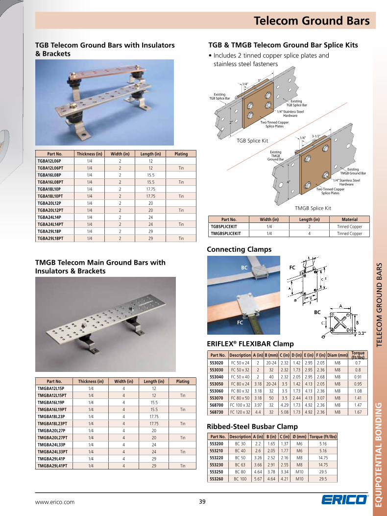
www.erico.com EQU
IPO
TEN
TIA
L B
ON
DIN
G
39
TELE
CO
M G
RO
un
D B
AR
S
TGB Telecom Ground Bars with Insulators & Brackets
TMGB Telecom Main Ground Bars with Insulators & Brackets
Connecting Clamps
ERIFLEX® FLEXIBAR Clamp
Ribbed-Steel Busbar Clamp
TGB & TMGB Telecom Ground Bar Splice Kits
TGB Splice Kit
TMGB Splice Kit
•Includes2tinnedcopperspliceplatesand stainless steel fasteners
Part No. Thickness (in) Width (in) Length (in) Plating
TGBA12L06P 1/4 2 12
TGBA12L06PT 1/4 2 12 Tin
TGBA16L08P 1/4 2 15.5
TGBA16L08PT 1/4 2 15.5 Tin
TGBA18L10P 1/4 2 17.75
TGBA18L10PT 1/4 2 17.75 Tin
TGBA20L12P 1/4 2 20
TGBA20L12PT 1/4 2 20 Tin
TGBA24L14P 1/4 2 24
TGBA24L14PT 1/4 2 24 Tin
TGBA29L18P 1/4 2 29
TGBA29L18PT 1/4 2 29 Tin
Part No. Thickness (in) Width (in) Length (in) Plating
TMGBA12L15P 1/4 4 12
TMGBA12L15PT 1/4 4 12 Tin
TMGBA16L19P 1/4 4 15.5
TMGBA16L19PT 1/4 4 15.5 Tin
TMGBA18L23P 1/4 4 17.75
TMGBA18L23PT 1/4 4 17.75 Tin
TMGBA20L27P 1/4 4 20
TMGBA20L27PT 1/4 4 20 Tin
TMGBA24L33P 1/4 4 24
TMGBA24L33PT 1/4 4 24 Tin
TMGBA29L41P 1/4 4 29
TMGBA29L41PT 1/4 4 29 Tin
Part No. Description A (in) B (mm) C (in) D (in) E (in) F (in) Diam (mm) Torque (ft/lbs)
553020 FC 50 x 24 2 20-24 2.32 1.42 2.95 2.05 M8 0.7
553030 FC 50 x 32 2 32 2.32 1.73 2.95 2.36 M8 0.8
553040 FC 50 x 40 2 40 2.32 2.05 2.95 2.68 M8 0.91
553050 FC 80 x 24 3.18 20-24 3.5 1.42 4.13 2.05 M8 0.95
553060 FC 80 x 32 3.18 32 3.5 1.73 4.13 2.36 M8 1.08
553070 FC 80 x 50 3.18 50 3.5 2.44 4.13 3.07 M8 1.41
568700 FC 100 x 32 3.97 32 4.29 1.73 4.92 2.36 M8 1.47
568730 FC 120 x 32 4.4 32 5.08 1.73 4.92 2.36 M8 1.67
Part No. Description A (in) B (in) C (in) Ø (mm) Torque (ft/lbs)
553200 BC 30 2.2 1.65 1.37 M6 5.16
553210 BC 40 2.6 2.05 1.77 M6 5.16
553220 BC 50 3.26 2.52 2.16 M8 14.75
553230 BC 63 3.66 2.91 2.55 M8 14.75
553250 BC 80 4.64 3.78 3.34 M10 29.5
553260 BC 100 5.67 4.64 4.21 M10 29.5
Part No. Width (in) Length (in) Material
TGBSPLICEKIT 1/4 2 Tinned Copper
TMGBSPLICEKIT 1/4 4 Tinned Copper
FC
BC FC
BC
Telecom Ground Bars
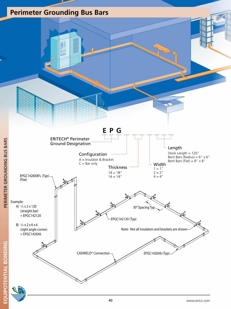
www.erico.comEQU
IPO
TEN
TIA
L B
ON
DIN
G
40
Example: A) 1/4 x 2 x 120 (straight bar) = EPGC142120
B) 1/4 x 2 x 6 x 6 (right angle corner) = EPGC1426X6
EPGC1428X8FL (Typ)(Flat)
30” Spacing Typ.
EPGC142120 (Typ)
Note: Not all insulators and brackets are shown
EPGC1426X6 (Typ)CADWELD® Connection
Width1 = 1”2 = 2”4 = 4”
ConfigurationA=Insulator&BracketC = Bar only
LengthStock Length = 120”Bent Bars (Radius) = 6” x 6”Bent Bars (Flat) = 8” x 8”
E P GERITECH® perimeter Ground Designation
Thickness18 = 1/8”14 = 1/4”
pER
IMET
ER G
RO
un
DIn
G B
uS
BA
RS
Perimeter Grounding Bus Bars
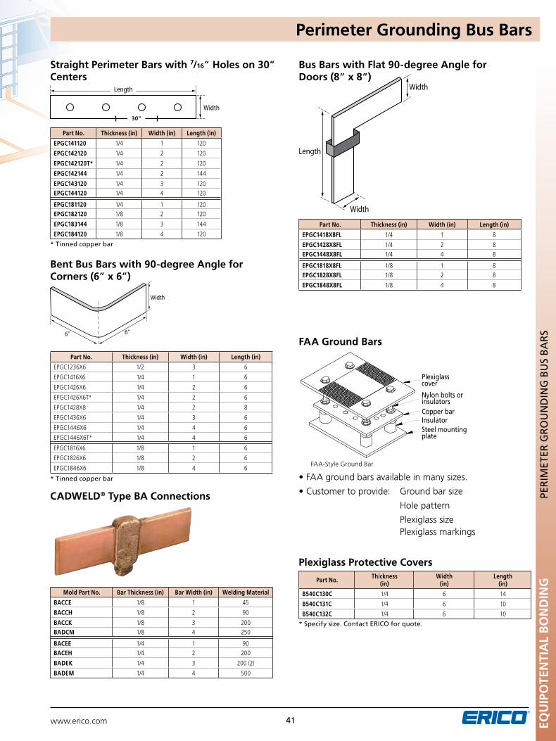
www.erico.com 41
FAA-Style Ground Bar
•FAAgroundbarsavailableinmanysizes.
•Customertoprovide: Groundbarsize
Hole pattern
Plexiglass size Plexiglass markings
FAA Ground Bars
Plexiglass Protective Covers
Part No. Thickness (in)
Width (in)
Length (in)
B540C130C 1/4 6 14
B540C131C 1/4 6 10
B540C132C 1/4 6 10
* Specify size. Contact ERICO for quote.
Width
6” 6”
Width
Width
Length
Bent Bus Bars with 90-degree Angle for Corners (6” x 6”)
* Tinned copper bar
Bus Bars with Flat 90-degree Angle for Doors (8” x 8”)
CADWELD® Type BA Connections
Part No. Thickness (in) Width (in) Length (in)
EPGC1418X8FL 1/4 1 8
EPGC1428X8FL 1/4 2 8EPGC1448X8FL 1/4 4 8
EPGC1818X8FL 1/8 1 8EPGC1828X8FL 1/8 2 8
EPGC1848X8FL 1/8 4 8
Mold Part No. Bar Thickness (in) Bar Width (in) Welding Material
BACCE 1/8 1 45
BACCH 1/8 2 90
BACCK 1/8 3 200BADCM 1/8 4 250
BACEE 1/4 1 90BACEH 1/4 2 200
BADEK 1/4 3 200 (2)
BADEM 1/4 4 500
Part No. Thickness (in) Width (in) Length (in)
EPGC1236X6 1/2 3 6
EPGC1416X6 1/4 1 6
EPGC1426X6 1/4 2 6
EPGC1426X6T* 1/4 2 6
EPGC1428X8 1/4 2 8
EPGC1436X6 1/4 3 6
EPGC1446X6 1/4 4 6
EPGC1446X6T* 1/4 4 6
EPGC1816X6 1/8 1 6
EPGC1826X6 1/8 2 6
EPGC1846X6 1/8 4 6
Straight Perimeter Bars with 7/16” Holes on 30” Centers
Width
Length
* Tinned copper bar
Part No. Thickness (in) Width (in) Length (in)
EPGC141120 1/4 1 120
EPGC142120 1/4 2 120
EPGC142120T* 1/4 2 120
EPGC142144 1/4 2 144
EPGC143120 1/4 3 120EPGC144120 1/4 4 120
EPGC181120 1/4 1 120EPGC182120 1/8 2 120
EPGC183144 1/8 3 144
EPGC184120 1/8 4 120
30”
EQu
IPO
TEN
TIA
L B
ON
DIN
GpE
RIM
ETER
GR
Ou
nD
InG
Bu
S B
AR
S
Perimeter Grounding Bus Bars
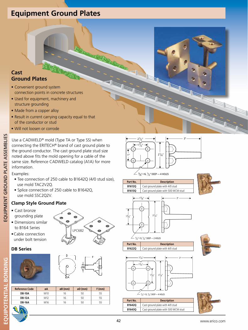
www.erico.com42
Part No. Description
B1612Q Cast ground plate with 4/0 stud
B1613Q Cast ground plate with 500 MCM stud
Part No. Description
B1622Q Cast ground plate with 4/0 stud
3/ 8“–16, 1/ 2“ DEEP — 4 HOLES
1”
2 1/ 2“
1 1/ 2“
2 1/ 4“
3“
3 1/ 4“1 3/ 4“
1 5/ 8“
1/ 2“–13, 1/ 2“ DEEP — 2 HOLES
3“
3 1/ 4“
1 3/ 4“
3 1/ 4“1 3/ 4“
1/ 2“–13, 1/ 2“ DEEP — 4 HOLES
3“
Part No. Description
B1642Q Cast ground plate with 4/0 stud
B1643Q Cast ground plate with 500 MCM stud
Reference Code øA øB (mm) øD (mm) F (mm)
DB-10A M10 16 50 55
DB-12A M12 16 50 55
DB-16A M16 16 50 55
DB Series
LPC682
Clamp Style Ground Plate
•Castbronze grounding plate
•Dimensionssimilar to B164 Series
•Cableconnection under bolt tension
Use a CADWELD® mold (Type TA or Type SS) when connecting the ERITECH® brand of cast ground plate to the ground conductor. The cast ground plate stud size noted above fits the mold opening for a cable of the same size. Reference CADWELD catalog (A1A) for more information.
Examples: •Teeconnectionof250cabletoB1642Q(4/0studsize), use mold TAC2V2Q. •Spliceconnectionof250cabletoB1642Q, use mold SSC2Q2V.
Equipment Ground PlatesEQ
uIP
OTE
NTI
AL
BO
ND
ING
EQu
IpM
EnT
GR
Ou
nD
pLA
TE A
SSEM
BLI
ES
Cast Ground Plates•Convenientgroundsystem
connection points in concrete structures
•Usedforequipment,machineryand structure grounding
•Madefromacopperalloy
•Resultincurrentcarryingcapacityequaltothat of the conductor or stud
•Willnotloosenorcorrode
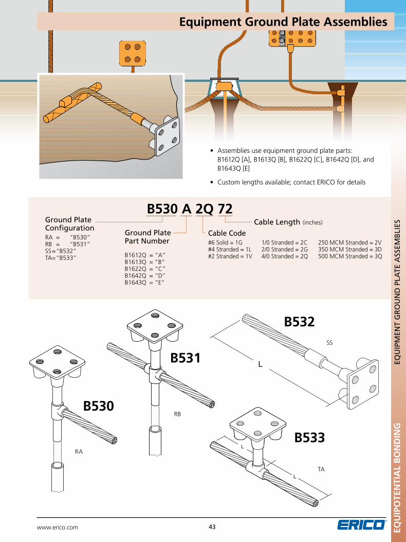
www.erico.com 43
A
• Assembliesuseequipmentgroundplateparts: B1612Q [A], B1613Q [B], B1622Q [C], B1642Q [D], and B1643Q [E]
• Customlengthsavailable;contactERICOfordetails
B530 A 2Q 72Ground plate ConfigurationRA = “B530” RB = “B531” SS = “B532” TA = “B533”
Ground plate part number
B1612Q = “A”B1613Q = “B”B1622Q = “C”B1642Q = “D”B1643Q = “E”
Cable Length (inches)
Cable Code#6 Solid = 1G 1/0 Stranded = 2C 250 MCM Stranded = 2V#4 Stranded = 1L 2/0 Stranded = 2G 350 MCM Stranded = 3D#2 Stranded = 1V 4/0 Stranded = 2Q 500 MCM Stranded = 3Q
RB
B531SS
B532
TA
B533RA
B530EQ
uIP
OTE
NTI
AL
BO
ND
ING
EQu
IpM
EnT
GR
Ou
nD
pLA
TE A
SSEM
BLI
ES
Equipment Ground Plate Assemblies
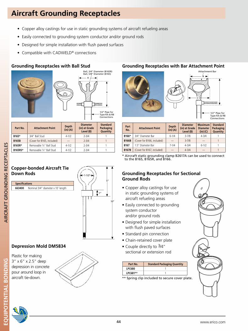
www.erico.comEQU
IPO
TEN
TIA
L B
ON
DIN
G
44
AIR
CR
AFT
GR
Ou
nD
InG
REC
EpTA
CLE
S
Grounding Receptacles with Ball Stud
B
A
1/2” pipe for Type RA & RB Connections
Ball, 3/4” Diameter (B165R) Ball, 5/8” Diameter (B165)
B
C
1/2” pipe for Type RA & RB Connections
Attachment Bar
Grounding Receptacles with Bar Attachment Point
Part No. Attachment Point Depth(in) (A)
Diameter (in) at Grade
Level (B)
Standard Packaging Quantity
B165* 3/4” Ball Stud 4-1/2 2-3/4 1
B165B (Cover for B165, included) — 2-3/4 1
B165R* Removable 3/4” Ball Stud 4-1/2 2-3/4 1
B165RS* Removable 3/4” Ball Stud 4-1/2 2-3/4 1
•Copperalloycastingsforusein static grounding systems of aircraft refueling areas
•Easilyconnectedtogroundingsystem conductor and/or ground rods
•Designedforsimpleinstallationwith flush paved surfaces
•Standardpinconnection
•Chain-retainedcoverplate
•Coupledirectlyto3/4” sectional or extension rod
Grounding Receptacles for Sectional Ground Rods
** Spring clip included to secure cover plate.
Part No. Standard Packaging Quantity
LPC680 1
LPC681** 1
Part No. Attachment Point Depth
(in) (A)
Diameter (in) at Grade
Level (B)
Maximum Diameter
(in) (C)
Standard Packaging Quantity
B166* 3/4” Diameter Bar 6-1/4 3-7/8 4-3/4 1
B166B (Cover for B166, included) — 3-7/8 — 1
B167 1.5” Diameter Bar 7-1/4 4-3/4 6-1/2 1
B167B (Cover for B167, included) — 4-3/4 — 1
• Copperalloycastingsforuseinstaticgroundingsystemsofaircraftrefuelingareas
• Easilyconnectedtogroundingsystemconductorand/orgroundrods
• Designedforsimpleinstallationwithflushpavedsurfaces
• CompatiblewithCADWELD® connections
Aircraft Grounding Receptacles
* Aircraft static grounding clamp B2617A can be used to connect to the B165, B165R, and B166.
Depression Mold DM5834
Plastic for making 3” x 6” x 2.5” deep depression in concrete pour around loop in aircraft tie-down.
Copper-bonded Aircraft Tie Down Rods
Specifications
663400 Nominal 3/4” diameter x 10’ length
1-1/2”
5”
10”
1”
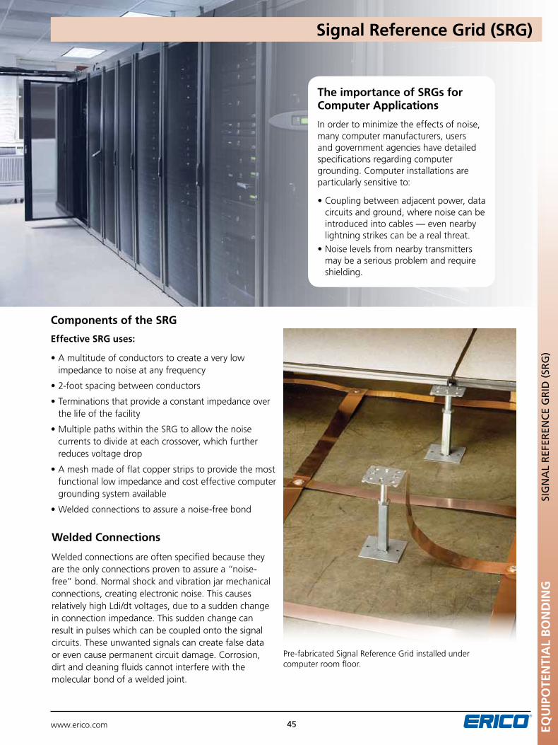
www.erico.com 45
Pre-fabricated Signal Reference Grid installed under computer room floor.
Components of the SRG
Effective SRG uses:
•Amultitudeofconductorstocreateaverylowimpedance to noise at any frequency
•2-footspacingbetweenconductors
•Terminationsthatprovideaconstantimpedanceoverthe life of the facility
•MultiplepathswithintheSRGtoallowthenoisecurrents to divide at each crossover, which further reduces voltage drop
•Ameshmadeofflatcopperstripstoprovidethemostfunctional low impedance and cost effective computer grounding system available
•Weldedconnectionstoassureanoise-freebond
Welded Connections
Welded connections are often specified because they are the only connections proven to assure a “noise-free” bond. Normal shock and vibration jar mechanical connections, creating electronic noise. This causes relatively high Ldi/dt voltages, due to a sudden change in connection impedance. This sudden change can result in pulses which can be coupled onto the signal circuits. These unwanted signals can create false data or even cause permanent circuit damage. Corrosion, dirt and cleaning fluids cannot interfere with the molecular bond of a welded joint.
The importance of SRGs for Computer Applications
In order to minimize the effects of noise, many computer manufacturers, users and government agencies have detailed specifications regarding computer grounding. Computer installations are particularly sensitive to:
•Couplingbetweenadjacentpower,datacircuits and ground, where noise can be introduced into cables — even nearby lightning strikes can be a real threat.
•Noiselevelsfromnearbytransmittersmay be a serious problem and require shielding.
EQu
IPO
TEN
TIA
L B
ON
DIN
GSI
Gn
AL
REF
EREn
CE
GR
ID (
SRG
)
Signal Reference Grid (SRG)
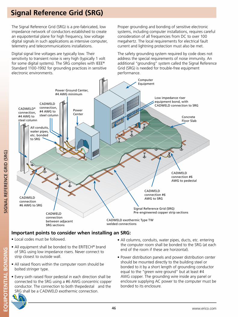
www.erico.com46
Signal Reference Grid (SRG)EQ
uIP
OTE
NTI
AL
BO
ND
ING
SIG
nA
L R
EFER
EnC
E G
RID
(SR
G)
The Signal Reference Grid (SRG) is a pre-fabricated, low impedance network of conductors established to create an equipotential plane for high frequency, low voltage digital signals in such applications as intensive computer, telemetry and telecommunications installations.
Digital signal line voltages are typically low. Their sensitivity to transient noise is very high (typically 1 volt for some digital systems). The SRG complies with IEEE® Standard 1100-1992 for grounding practices in sensitive electronic environments.
Proper grounding and bonding of sensitive electronic systems, including computer installations, requires careful consideration of all frequencies from DC to over 100 megahertz. The local requirements for electrical fault current and lightning protection must also be met.
The safety grounding system required by code does not address the special requirements of noise immunity. An additional “grounding” system called the Signal Reference Grid (SRG) is needed for trouble-free equipment performance.
•Localcodesmustbefollowed.
•AllequipmentshallbebondedtotheERITECH® brand of SRG using low impedance risers. Never connect to strip closest to outside wall.
•Allraisedfloorswithinthecomputerroomshouldbe bolted stringer type.
•Everysixthraisedfloorpedestalineachdirectionshallbeconnected to the SRG using a #6 AWG concentric copper conductor. The connection to both thepedestal and the SRG shall be a CADWELD exothermic connection.
•Allcolumns,conduits,waterpipes,ducts,etc.entering the computer room shall be bonded to the SRG (at each end of the room if these are horizontal).
•Powerdistributionpanelsandpowerdistributioncenter should be mounted directly to the building steel or bonded to it by a short length of grounding conductor equal to the “green wire ground” but at least #4 AWG copper. The grounding wire inside any panel or enclosure supplying AC power to the computer must be bonded to its enclosure.
Important points to consider when installing an SRG:
Computer Equipment
power Ground Center, #4 AWG minimum
All conduits, water pipes, etc. bonded to SRG
Low impedance riser equipment bond, with CADWELD connection to SRG
power Center
Concrete Floor Slab
CADWELD connection #6 AWG to pedestal
CADWELD exothermic Type TW welded connections
CADWELD connection between adjacent SRG sections
CADWELD connection #6 AWG to SRG
CADWELD® connection, #4 AWG to steel column
CADWELD connection, #4 AWG to steel column
Signal Reference Grid (SRG) pre-engineered copper strip sections
CADWELD connection #6 AWG to SRG
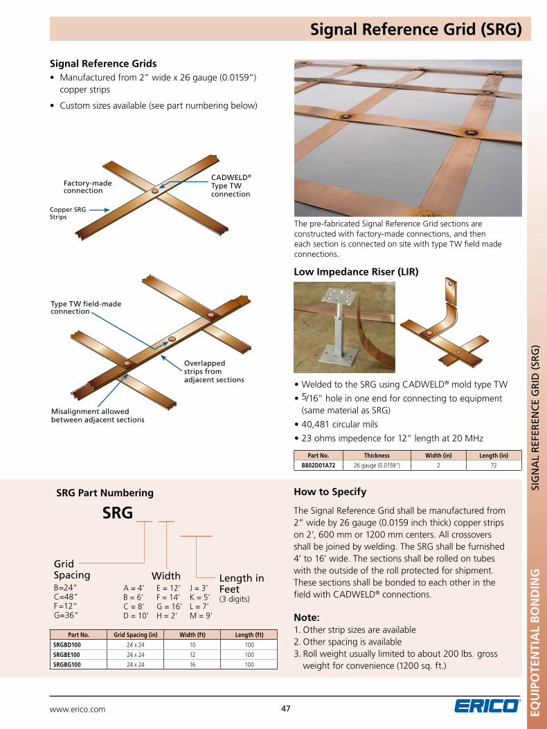
www.erico.com EQU
IPO
TEN
TIA
L B
ON
DIN
G
47
SIG
nA
L R
EFER
EnC
E G
RID
(SR
G)
• Manufacturedfrom2”widex26gauge(0.0159”) copper strips
• Customsizesavailable(seepartnumberingbelow)
Copper SRG Strips
CADWELD® Type TW connection
Factory-made connection
Type TW field-made connection
Overlapped strips from adjacent sections
Misalignment allowed between adjacent sections
How to Specify
The Signal Reference Grid shall be manufactured from 2” wide by 26 gauge (0.0159 inch thick) copper strips on 2’, 600 mm or 1200 mm centers. All crossovers shall be joined by welding. The SRG shall be furnished 4’ to 16’ wide. The sections shall be rolled on tubes with the outside of the roll protected for shipment. These sections shall be bonded to each other in the field with CADWELD® connections.
Note: 1. Other strip sizes are available 2. Other spacing is available 3. Roll weight usually limited to about 200 lbs. gross
weight for convenience (1200 sq. ft.)
The pre-fabricated Signal Reference Grid sections are constructed with factory-made connections, and then each section is connected on site with type TW field made connections.
Signal Reference Grids
SRG
Grid SpacingB = 24”C = 48”F = 12”G = 36”
A = 4’ E = 12’ J = 3’B = 6’ F = 14’ K = 5’C = 8’ G = 16’ L = 7’D = 10’ H = 2’ M = 9’
Length in Feet(3 digits)
Width
SRG Part Numbering
Part No. Grid Spacing (in) Width (ft) Length (ft)
SRGBD100 24 x 24 10 100
SRGBE100 24 x 24 12 100
SRGBG100 24 x 24 16 100
Signal Reference Grid (SRG)
Low Impedance Riser (LIR)
•WeldedtotheSRGusingCADWELD® mold type TW
•5/16” hole in one end for connecting to equipment (same material as SRG)
•40,481circularmils
•23ohmsimpedencefor12”lengthat20MHz
Part No. Thickness Width (in) Length (in)
B802D01A72 26 gauge (0.0159") 2 72
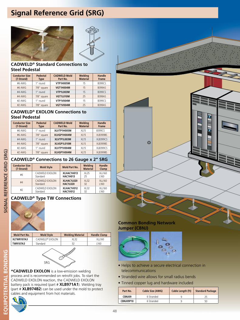
www.erico.comEQU
IPO
TEN
TIA
L B
ON
DIN
G
48
CADWELD® Standard Connections to Steel Pedestal
CADWELD® EXOLON Connections to Steel Pedestal
CADWELD® Connections to 26 Gauge x 2” SRG
SRG
*CADWELD EXOLON is a low-emission welding process and is recommended on retrofit jobs. To start the CADWELDEXOLONreaction,theCADWELDEXOLONbattery pack is required (part # XLB971A1). Welding tray (part # XLB974B2) can be used under the mold to protect cables and equipment from hot materials.
Conductor Size(7-Strand)
Pedestal Type
CADWELD Mold Part No.
Welding Material
Handle Frame
#6 AWG 1” round VTP1H005M 15 B399CS
#6 AWG 7/8” square VGT1H004M 15 B399AS
#4 AWG 1” round VTP1L003M 15 B399CS
#4 AWG 7/8” square VGT1L010M 25 B399AS
#2 AWG 1” round VTP1V004M 15 B399CS
#2 AWG 7/8” square VGT1V004M 25 B399AS
Conductor Size(7-Strand)
Pedestal Type
CADWELD Mold Part No.
Welding Material
Handle Frame
#6 AWG 1” round XLVTP1H005M XL15 B399CS
#6 AWG 7/8” square XLVGP1H004M XL15 XLB399BS
#4 AWG 1” round XLVTP1L003M XL15 XLB399CS
#4 AWG 7/8” square XLVGP1L010M XL15 XLB399BS
#2 AWG 1” round XLVTP1V004M XL15 XLB399CS
#2 AWG 7/8” square XLVGP1V004M XL15 XLB399BS
Conductor Size(7-Strand) Mold Style Mold Part No. Welding
MaterialHandle Clamp
#6 CADWELDEXOLONStandard
XLHAC1H013 HAC1H013
XL25 25
XLL160 L160
#4 CADWELDEXOLONStandard
XLHAC1L020 HAC1L020
XL32 32
XLL160 L160
#2 CADWELDEXOLONStandard
XLHAC1V012 HAC1V012
XL32 32
XLL160 L160
SIG
nA
L R
EFER
EnC
E G
RID
(SR
G)
CADWELD® Type TW Connections
Mold Part No. Mold Style Welding Material Handle Clamp
XLTWR107A3 CADWELD®EXOLON XL32 XLL160
TWR107A3 Standard 32 L160
Signal Reference Grid (SRG)
Common Bonding Network Jumper (CBNJ)
•Helpstoachieveasecureelectricalconnectionintelecommunications
•Strandedwireallowsforsmallradiusbends
•Tinnedcopperlugandhardwareincluded
Part No. Cable Size (AWG) Cable Length (ft) Standard Package
CBNJ09 6 Stranded 9 25
CBNJ09P10 6 Stranded 9 50
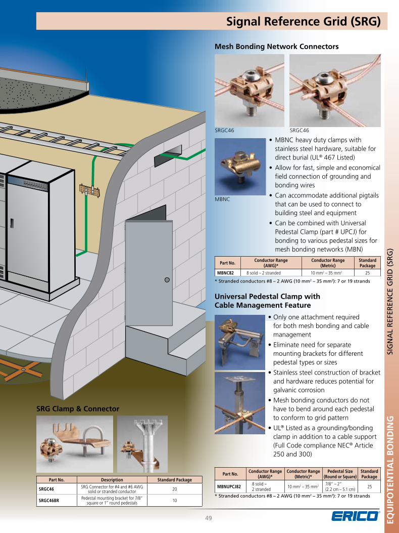
www.erico.com EQU
IPO
TEN
TIA
L B
ON
DIN
G
49
SIG
nA
L R
EFER
EnC
E G
RID
(SR
G)
SRG Clamp & Connector
Mesh Bonding Network Connectors
•MBNCheavydutyclampswithstainless steel hardware, suitable for direct burial (UL® 467 Listed)
•Allowforfast,simpleandeconomical field connection of grounding and bonding wires
•Canaccommodateadditionalpigtails that can be used to connect to
building steel and equipment
•CanbecombinedwithUniversalPedestal Clamp (part # UPCJ) for bonding to various pedestal sizes for mesh bonding networks (MBN)
* Stranded conductors #8 – 2 AWG (10 mm2 – 35 mm2): 7 or 19 strands
Part No. Conductor Range (AWG)*
Conductor Range (Metric)
Standard Package
MBNC82 8 solid – 2 stranded 10 mm2 – 35 mm2 25
universal Pedestal Clamp with Cable Management Feature
•Onlyoneattachmentrequiredfor both mesh bonding and cable management
•Eliminateneedforseparatemounting brackets for different pedestal types or sizes
•Stainlesssteelconstructionofbracket and hardware reduces potential for galvanic corrosion
•Meshbondingconductorsdonothave to bend around each pedestal to conform to grid pattern
•UL® Listed as a grounding/bonding clamp in addition to a cable support (Full Code compliance NEC® Article 250 and 300)
* Stranded conductors #8 – 2 AWG (10 mm2 – 35 mm2): 7 or 19 strands
Part No. Conductor Range(AWG)*
Conductor Range(Metric)*
Pedestal Size(Round or Square)
Standard Package
MBNuPCJ82 8 solid – 2 stranded 10 mm2 – 35 mm2 7/8” – 2”
(2.2 cm – 5.1 cm) 25Part No. Description Standard Package
SRGC46 SRG Connector for #4 and #6 AWG solid or stranded conductor 20
SRGC46BR Pedestal mounting bracket for 7/8” square or 1” round pedestals 10
Signal Reference Grid (SRG)
SRGC46
MBNC
SRGC46
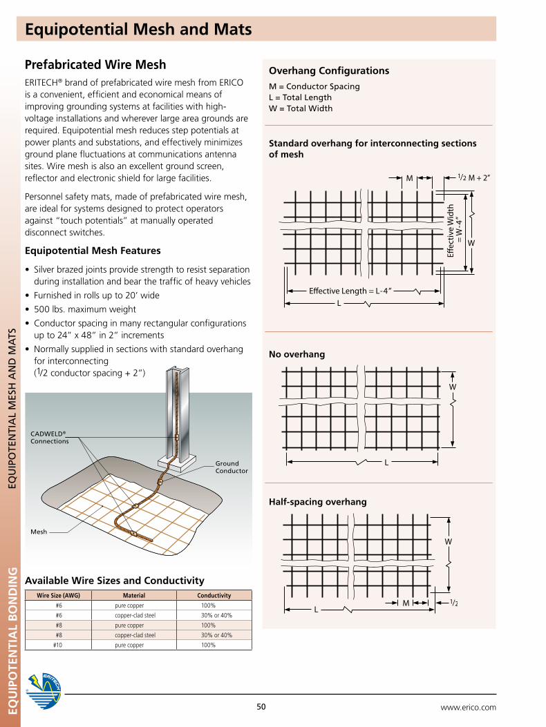
www.erico.comEQU
IPO
TEN
TIA
L B
ON
DIN
G
Ground Conductor
CADWELD® Connections
Mesh
50
EQu
IpO
TEn
TIA
L M
ESH
An
D M
ATS
Equipotential Mesh and Mats
Prefabricated Wire Mesh ERITECH® brand of prefabricated wire mesh from ERICO is a convenient, efficient and economical means of improving grounding systems at facilities with high-voltage installations and wherever large area grounds are required. Equipotential mesh reduces step potentials at power plants and substations, and effectively minimizes ground plane fluctuations at communications antenna sites. Wire mesh is also an excellent ground screen, reflector and electronic shield for large facilities.
Personnel safety mats, made of prefabricated wire mesh, are ideal for systems designed to protect operators against “touch potentials” at manually operated disconnect switches.
Equipotential Mesh Features
• Silverbrazedjointsprovidestrengthtoresistseparation during installation and bear the traffic of heavy vehicles
•Furnishedinrollsupto20’wide
•500lbs.maximumweight
•Conductorspacinginmanyrectangularconfigurations up to 24” x 48” in 2” increments
•Normallysuppliedinsectionswithstandardoverhangfor interconnecting (1/2 conductor spacing + 2”)
Available Wire Sizes and Conductivity
Overhang Configurations
M = Conductor Spacing L = Total Length W = Total Width
Standard overhang for interconnecting sections of mesh
No overhang
Half-spacing overhang
Wire Size (AWG) Material Conductivity
#6 pure copper 100%
#6 copper-clad steel 30% or 40%
#8 pure copper 100%
#8 copper-clad steel 30% or 40%
#10 pure copper 100%
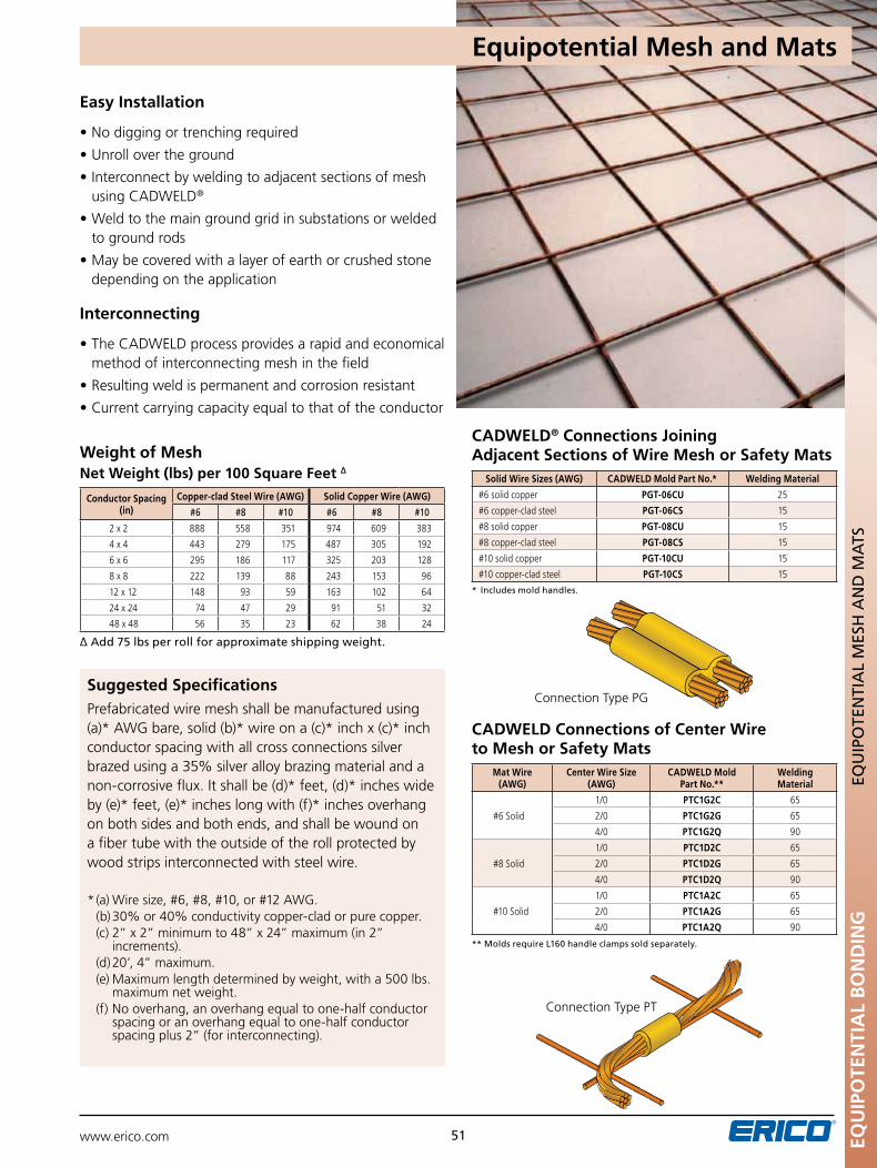
www.erico.com 51
Equipotential Mesh and Mats
Easy Installation
•Nodiggingortrenchingrequired
•Unrollovertheground
•Interconnectbyweldingtoadjacentsectionsofmesh using CADWELD®
•Weldtothemaingroundgridinsubstationsorwelded to ground rods
•Maybecoveredwithalayerofearthorcrushedstone depending on the application
Interconnecting
•TheCADWELDprocessprovidesarapidandeconomical method of interconnecting mesh in the field
•Resultingweldispermanentandcorrosionresistant
•Currentcarryingcapacityequaltothatoftheconductor
Weight of MeshNet Weight (lbs) per 100 Square Feet ∆
∆ Add 75 lbs per roll for approximate shipping weight.
Suggested SpecificationsPrefabricated wire mesh shall be manufactured using (a)* AWG bare, solid (b)* wire on a (c)* inch x (c)* inch conductor spacing with all cross connections silver brazed using a 35% silver alloy brazing material and a non-corrosive flux. It shall be (d)* feet, (d)* inches wide by (e)* feet, (e)* inches long with (f)* inches overhang on both sides and both ends, and shall be wound on a fiber tube with the outside of the roll protected by wood strips interconnected with steel wire.
* (a) Wire size, #6, #8, #10, or #12 AWG. (b) 30% or 40% conductivity copper-clad or pure copper. (c) 2” x 2” minimum to 48” x 24” maximum (in 2”
increments). (d) 20’, 4” maximum. (e) Maximum length determined by weight, with a 500 lbs. maximum net weight. (f) No overhang, an overhang equal to one-half conductor spacing or an overhang equal to one-half conductor
spacing plus 2” (for interconnecting).
Conductor Spacing (in)
Copper-clad Steel Wire (AWG) Solid Copper Wire (AWG)
#6 #8 #10 #6 #8 #10
2 x 2 888 558 351 974 609 383
4 x 4 443 279 175 487 305 192
6 x 6 295 186 117 325 203 128
8 x 8 222 139 88 243 153 96
12 x 12 148 93 59 163 102 64
24 x 24 74 47 29 91 51 32
48 x 48 56 35 23 62 38 24
* Includes mold handles.
CADWELD® Connections Joining Adjacent Sections of Wire Mesh or Safety Mats
Solid Wire Sizes (AWG) CADWELD Mold Part No.* Welding Material
#6 solid copper PGT-06Cu 25
#6 copper-clad steel PGT-06CS 15
#8 solid copper PGT-08Cu 15
#8 copper-clad steel PGT-08CS 15
#10 solid copper PGT-10Cu 15
#10 copper-clad steel PGT-10CS 15
CADWELD Connections of Center Wire to Mesh or Safety Mats
** Molds require L160 handle clamps sold separately.
Connection Type PG
Connection Type PT
Mat Wire (AWG)
Center Wire Size (AWG)
CADWELD Mold Part No.**
Welding Material
#6 Solid
1/0 PTC1G2C 65
2/0 PTC1G2G 65
4/0 PTC1G2Q 90
#8 Solid
1/0 PTC1D2C 65
2/0 PTC1D2G 65
4/0 PTC1D2Q 90
#10 Solid
1/0 PTC1A2C 65
2/0 PTC1A2G 65
4/0 PTC1A2Q 90
EQu
IPO
TEN
TIA
L B
ON
DIN
GEQ
uIp
OTE
nTI
AL
MES
H A
nD
MA
TS
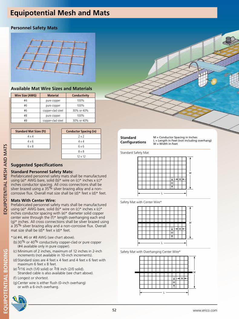
Personnel Safety Mats
Suggested Specifications
Standard Personnel Safety Mats: Prefabricated personnel safety mats shall be manufactured using (a)* AWG bare, solid (b)* wire on (c)* inches x (c)* inches conductor spacing. All cross connections shall be silver brazed using a 35% silver brazing alloy and a non-corrosive flux. Overall mat size shall be (d)* feet x (d)* feet.
Mats With Center Wire: Prefabricated personnel safety mats shall be manufactured using (a)* AWG bare, solid (b)* wire on (c)* inches x (c)* inches conductor spacing with (e)* diameter solid copper center wire through the (f)* length overhanging each end (g)* inches. All cross connections shall be silver brazed using a 35% silver brazing alloy and a non-corrosive flux. Overall mat size shall be (d)* feet x (d)* feet.
* (a) #4, #6 or #8 AWG (see chart above). (b) 30% or 40% conductivity copper-clad or pure copper (#4 available only in pure copper). (c) Minimum of 2 inches, maximum of 12 inches in 2-inch increments (not available in 10-inch increments). (d) Standard sizes are 4 feet x 4 feet and 4 feet x 6 feet with maximum 6 feet x 8 feet. (e) 5/16 inch (1/0 solid) or 3/8 inch (2/0 solid). Stranded cable is also available (see chart above). (f) Longest or shortest. (g) Center wire is either flush (0-inch overhang) or with a 6-inch overhang.
Available Mat Wire Sizes and MaterialsWire Size (AWG) Material Conductivity
#4 pure copper 100%
#6 pure copper 100%
#6 copper-clad steel 30% or 40%
#8 pure copper 100%
#8 copper-clad steel 30% or 40%
Standard Mat Sizes (ft)
4 x 4
4 x 6
6 x 8
Conductor Spacing (in)
2 x 2
4 x 4
6 x 6
8 x 8
12 x 12
EQu
IPO
TEN
TIA
L B
ON
DIN
GEQ
uIp
OTE
nTI
AL
MES
H A
nD
MA
TS
www.erico.com52
Safety Mat with Center Wire*
Safety Mat with Overhanging Center Wire*
M = Conductor Spacing in InchesL = Length in Feet (not including overhang)W = Width in Feet
Standard Configurations
Standard Safety Mat
Equipotential Mesh and Mats
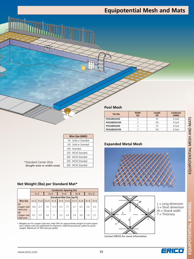
EQu
IPO
TEN
TIA
L B
ON
DIN
GEQ
uIp
OTE
nTI
AL
MES
H A
nD
MA
TS
www.erico.com 53
Pool Mesh
*Standard Center Wire (length-wise or width-wise)
Wire Size (AWG)
1/0 Solid or Stranded
2/0 Solid or Stranded
4/0 Stranded
250 MCM Stranded
300 MCM Stranded
350 MCM Stranded
500 MCM Stranded
* Weights are for copper-clad wire. Add 10% for approximate weight of solid copper wire. Safety mats are palletized for shipment. Add 50 pounds per pallet for gross weight. Maximum of 100 mats per pallet.
Conductor Spacing (in)
2 x 2 4 x 4 6 x 6 8 x 8 12 x 12
Standard Mat Size (sq ft)
Wire Size 4 x 4 4 x 6 4 x 4 4 x 6 4 x 4 4 x 6 4 x 4 4 x 6 4 x 4 4 x 6#6 Copper-clad steel wire
14.6 21.7 7.6 11.2 5.3 7.7 4.1 6.0 2.9 4.2
#8 Copper-clad steel wire
9.2 13.7 4.8 7.1 3.3 4.9 2.6 3.8 1.9 2.7
Net Weight (lbs) per Standard Mat*
Part No. Width (ft)
Length (ft)
Conductor (AWG)
POOLMESH250 2 50 8 Solid
POOLMESH2100 2 100 8 Solid
POOLMESH350 3 50 8 Solid
POOLMESH3100 3 100 8 Solid
Expanded Metal Mesh
L = Long dimensionS = Short dimensionW = Strand widthT = Thickness
Contact ERICO for more information.
L
S
W
T
Equipotential Mesh and Mats
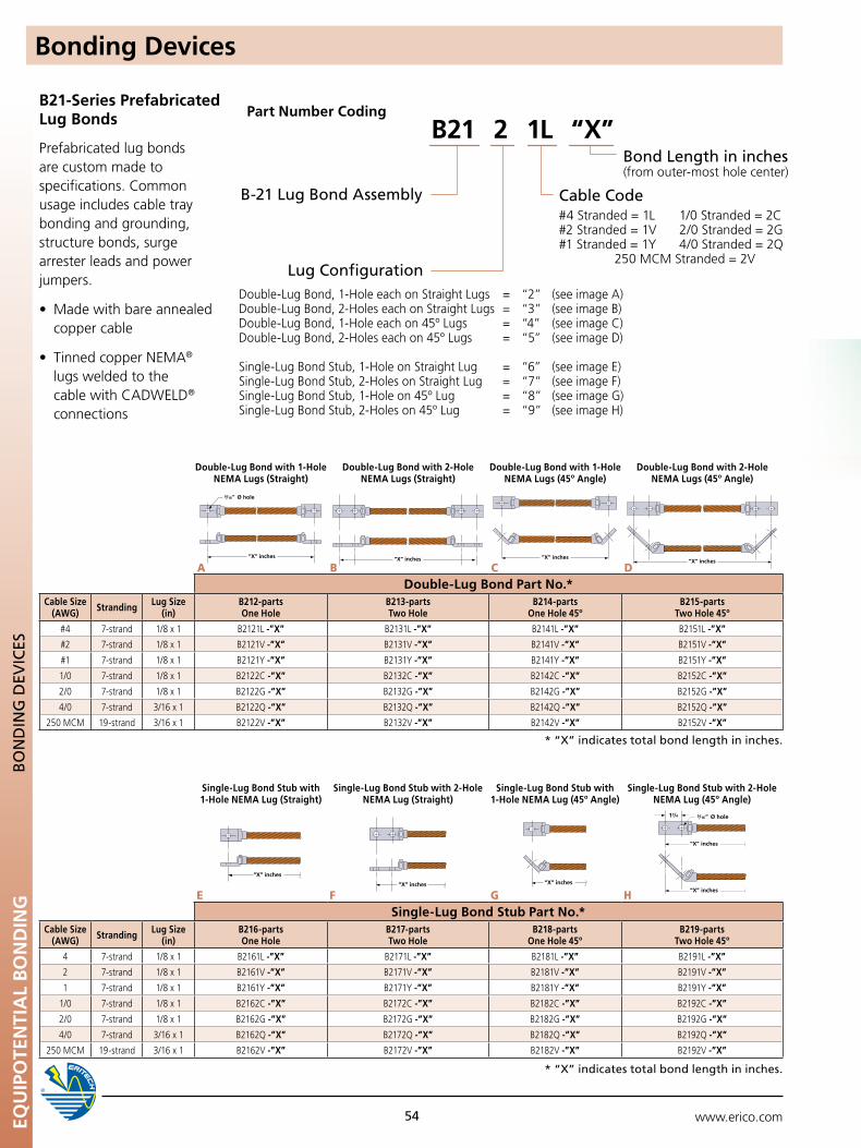
www.erico.comEQU
IPO
TEN
TIA
L B
ON
DIN
G
54
Double-Lug Bond with 1-Hole NEMA Lugs (Straight)
Double-Lug Bond with 2-Hole NEMA Lugs (Straight)
Double-Lug Bond with 1-Hole NEMA Lugs (45º Angle)
Double-Lug Bond with 2-Hole NEMA Lugs (45º Angle)
Double-Lug Bond Part No.*Cable Size
(AWG) Stranding Lug Size (in)
B212-parts One Hole
B213-parts Two Hole
B214-parts One Hole 45º
B215-parts Two Hole 45º
#4 7-strand 1/8 x 1 B2121L -”X” B2131L -”X” B2141L -”X” B2151L -”X”
#2 7-strand 1/8 x 1 B2121V -”X” B2131V -”X” B2141V -”X” B2151V -”X”
#1 7-strand 1/8 x 1 B2121Y -”X” B2131Y -”X” B2141Y -”X” B2151Y -”X”
1/0 7-strand 1/8 x 1 B2122C -”X” B2132C -”X” B2142C -”X” B2152C -”X”
2/0 7-strand 1/8 x 1 B2122G -”X” B2132G -”X” B2142G -”X” B2152G -”X”
4/0 7-strand 3/16 x 1 B2122Q -”X” B2132Q -”X” B2142Q -”X” B2152Q -”X”
250 MCM 19-strand 3/16 x 1 B2122V -”X” B2132V -”X” B2142V -”X” B2152V -”X”
Single-Lug Bond Stub with 1-Hole NEMA Lug (Straight)
Single-Lug Bond Stub with 2-Hole NEMA Lug (Straight)
Single-Lug Bond Stub with 1-Hole NEMA Lug (45º Angle)
Single-Lug Bond Stub with 2-Hole NEMA Lug (45º Angle)
Single-Lug Bond Stub Part No.*Cable Size
(AWG) Stranding Lug Size (in)
B216-parts One Hole
B217-parts Two Hole
B218-parts One Hole 45º
B219-parts Two Hole 45º
4 7-strand 1/8 x 1 B2161L -”X” B2171L -”X” B2181L -”X” B2191L -”X”
2 7-strand 1/8 x 1 B2161V -”X” B2171V -”X” B2181V -”X” B2191V -”X”
1 7-strand 1/8 x 1 B2161Y -”X” B2171Y -”X” B2181Y -”X” B2191Y -”X”
1/0 7-strand 1/8 x 1 B2162C -”X” B2172C -”X” B2182C -”X” B2192C -”X”
2/0 7-strand 1/8 x 1 B2162G -”X” B2172G -”X” B2182G -”X” B2192G -”X”
4/0 7-strand 3/16 x 1 B2162Q -”X” B2172Q -”X” B2182Q -”X” B2192Q -”X”
250 MCM 19-strand 3/16 x 1 B2162V -”X” B2172V -”X” B2182V -”X” B2192V -”X”
BO
nD
InG
DEV
ICES
Bonding Devices
* “X” indicates total bond length in inches.
* “X” indicates total bond length in inches.
B21-Series Prefabricated Lug Bonds
Prefabricated lug bonds are custom made to specifications. Common usage includes cable tray bonding and grounding, structure bonds, surge arrester leads and power jumpers.
•Madewithbareannealed copper cable
•TinnedcopperNEMA® lugs welded to the cable with CADWELD® connections
Part Number Coding
Cable Code #4 Stranded = 1L 1/0 Stranded = 2C#2 Stranded = 1V 2/0 Stranded = 2G#1 Stranded = 1Y 4/0 Stranded = 2Q
250 MCM Stranded = 2V
Bond Length in inches (from outer-most hole center)
B21 2 1L “X”
B-21 Lug Bond Assembly
Double-Lug Bond, 1-Hole each on Straight Lugs = “2” (see image A) Double-Lug Bond, 2-Holes each on Straight Lugs = “3” (see image B) Double-Lug Bond, 1-Hole each on 45º Lugs = “4” (see image C) Double-Lug Bond, 2-Holes each on 45º Lugs = “5” (see image D)
Single-Lug Bond Stub, 1-Hole on Straight Lug = “6” (see image E) Single-Lug Bond Stub, 2-Holes on Straight Lug = “7” (see image F) Single-Lug Bond Stub, 1-Hole on 45º Lug = “8” (see image G) Single-Lug Bond Stub, 2-Holes on 45º Lug = “9” (see image H)
Lug Configuration
A B C D
E F G H
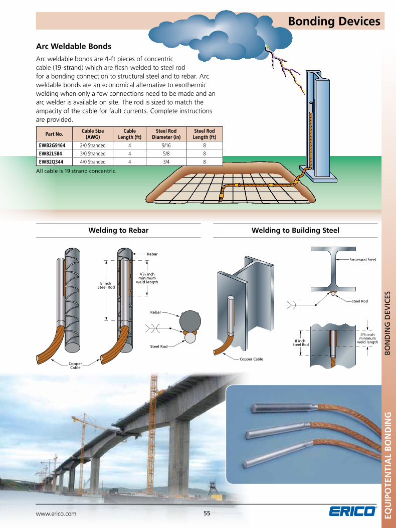
www.erico.com 55
Bonding Devices
Structural Steel
Copper Cable
Steel Rod
8 inch Steel Rod
4 1/4 inch
minimumweld length
Rebar
Rebar
CopperCable
Steel Rod
8 inch Steel Rod
4 1/4 inch
minimumweld length
Welding to Rebar Welding to Building Steel
Arc Weldable Bonds
Arc weldable bonds are 4-ft pieces of concentric cable (19-strand) which are flash-welded to steel rod for a bonding connection to structural steel and to rebar. Arc weldable bonds are an economical alternative to exothermic welding when only a few connections need to be made and an arc welder is available on site. The rod is sized to match the ampacity of the cable for fault currents. Complete instructions are provided.
All cable is 19 strand concentric.
Part No. Cable Size (AWG)
Cable Length (ft)
Steel Rod Diameter (in)
Steel Rod Length (ft)
EWB2G9164 2/0 Stranded 4 9/16 8
EWB2L584 3/0 Stranded 4 5/8 8
EWB2Q344 4/0 Stranded 4 3/4 8
EQu
IPO
TEN
TIA
L B
ON
DIN
GB
On
DIn
G D
EVIC
ES
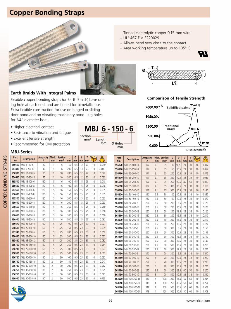
www.erico.comEQU
IPO
TEN
TIA
L B
ON
DIN
G
56
CO
ppER
BO
nD
InG
STR
ApS
Copper Bonding Straps
Earth Braids With Integral Palms
MBJ 6 - 150 - 6Section
mm2 Length mm Ø Holes
mm
MBJ-Series Displacement
Solidified palms
Traditional braid
Comparison of Tensile Strength
Part No. Description Ampacity
AThick. mm
Section mm2
L mm
Ø mm
J mm
T mm
556600 MBJ 6-150-6 40 1.1 6 150 6.5 13 23 10 0.010
563410 MBJ 6-200-6 40 1.1 6 200 6.5 13 23 10 0.0167
556930 MBJ 10-200-6 75 1.1 10 200 6.5 12 22 10 0.022
556610 MBJ 10-300-6 75 1.1 10 300 6.5 12 22 10 0.033
563540 MBJ 16-100-6 120 1.5 16 100 6.5 15 25 10 0.018
556620 MBJ 16-100-8 120 1.5 16 100 8.5 15 25 10 0.018
563550 MBJ 16-150-6 120 1.5 16 150 6.5 15 25 10 0.035
556630 MBJ 16-150-8 120 1.5 16 150 8.5 15 25 10 0.035
563300 MBJ 16-200-6 120 1.5 16 200 6.5 15 25 10 0.033
556640 MBJ 16-200-8 120 1.5 16 200 8.5 15 25 10 0.033
556650 MBJ 16-250-8 120 1.5 16 250 8.5 15 25 10 0.040
563320 MBJ 16-300-6 120 1.5 16 300 6.5 15 25 10 0.050
556660 MBJ 16-300-8 120 1.5 16 300 8.5 15 25 10 0.050
556940 MBJ 16-500-8 120 1.5 16 500 8.5 15 25 10 0.082
556670 MBJ 25-100-10 150 1.5 25 100 10.5 23 33 10 0.027
556680 MBJ 25-150-10 150 1.5 25 150 10.5 23 33 10 0.039
563340 MBJ 25-200-6 150 1.5 25 200 6.5 23 33 10 0.052
556690 MBJ 25-200-10 150 1.5 25 200 10.5 23 33 10 0.052
563430 MBJ 25-200-12 150 1.5 25 200 12.5 23 33 10 0.052
556700 MBJ 25-250-10 150 1.5 25 250 10.5 23 33 10 0.064
556710 MBJ 25-300-10 150 1.5 25 300 10.5 23 33 10 0.077
556950 MBJ 25-500-10 150 1.5 25 500 10.5 23 33 10 0.013
556720 MBJ 30-100-10 180 2 30 100 10.5 23 33 10 0.032
556730 MBJ 30-150-10 180 2 30 150 10.5 23 33 10 0.047
556740 MBJ 30-200-10 180 2 30 200 10.5 23 33 10 0.062
556750 MBJ 30-250-10 180 2 30 250 10.5 23 33 10 0.075
556760 MBJ 30-300-10 180 2 30 300 10.5 23 33 10 0.092
556960 MBJ 30-500-10 180 2 30 500 10.5 23 33 10 0.155
Part No. Description Ampacity
AThick. mm
Section mm2
L mm
Ø mm
J mm
T mm
556770 MBJ 35-100-10 197 2.1 35 100 10.5 23 33 10 0.037
556780 MBJ 35-150-10 197 2.1 35 150 10.5 23 33 10 0.054
556790 MBJ 35-200-10 197 2.1 35 200 10.5 23 33 10 0.072
556800 MBJ 35-250-10 197 2.1 35 250 10.5 23 33 10 0.089
565000 MBJ 35-250-25 197 2.1 35 250 25.5 40 50 10 0.089
556810 MBJ 35-300-10 197 2.1 35 300 10.5 23 33 10 0.110
556970 MBJ 35-500-10 197 2.1 35 500 10.5 23 33 10 0.180
556820 MBJ 50-100-10 250 2.5 50 100 10.5 28 38 10 0.052
556830 MBJ 50-150-10 250 2.5 50 150 10.5 28 38 10 0.077
563350 MBJ 50-200-6 250 2.5 50 200 6.5 28 38 10 0.120
556840 MBJ 50-200-10 250 2.5 50 200 10.5 28 38 10 0.120
563440 MBJ 50-200-12 250 2.5 50 200 12.5 28 38 10 0.120
563360 MBJ 50-200-16 250 2.5 50 200 16.5 28 38 10 0.110
563370 MBJ 50-200-18 250 2.5 50 200 18.5 28 38 10 0.110
556850 MBJ 50-250-10 250 2.5 50 250 10.5 28 38 10 0.127
563380 MBJ 50-300-6 250 2.5 50 300 6.5 28 38 10 0.150
556860 MBJ 50-300-10 250 2.5 50 300 10.5 28 38 10 0.153
563390 MBJ 50-300-16 250 2.5 50 300 16.5 28 38 10 0.150
563400 MBJ 50-300-18 250 2.5 50 300 18.5 28 38 10 0.140
556980 MBJ 50-500-10 250 2.5 50 500 10.5 28 38 10 0.255
563560 MBJ 50-500-12 250 2.5 50 500 12.5 28 38 10 0.255
563450 MBJ 70-300-6 290 5 70 300 6.5 28 38 10 0.210
563460 MBJ 70-300-10 290 5 70 300 10.5 28 38 10 0.210
563420 MBJ 70-300-12 290 5 70 300 12.5 28 38 10 0.210
563470 MBJ 70-300-16 290 5 70 300 16.5 28 38 10 0.200
563480 MBJ 70-300-22 290 3.5 70 300 22.5 40 50 10 0.200
563490 MBJ 70-500-10 290 5 70 500 10.5 28 38 10 0.340
563500 MBJ 100-250-16 349 4 100 250 16.5 50 60 10 0.254
563510 MBJ 100-250-30 349 4 100 250 30.5 50 60 10 0.254
563520 MBJ 100-500-16 349 4 100 500 16.5 50 60 10 0.508
563530 MBJ 100-500-30 349 4 100 500 30.5 50 60 10 0.508
Flexible copper bonding straps (or Earth Braids) have one lug hole at each end, and are tinned for bimetallic use. Extra flexible construction for use on hinged or sliding door bond and on vibrating machinery bond. Lug holes for 1/4” diameter bolt.
•Higherelectricalcontact
•Resistancetovibrationandfatigue
•Excellenttensilestrength
•RecommendedforEMIprotection
– Tinned electrolytic copper 0.15 mm wire – UL® 467 File E220029 – Allows bend very close to the contact – Area working temperature up to 105° C
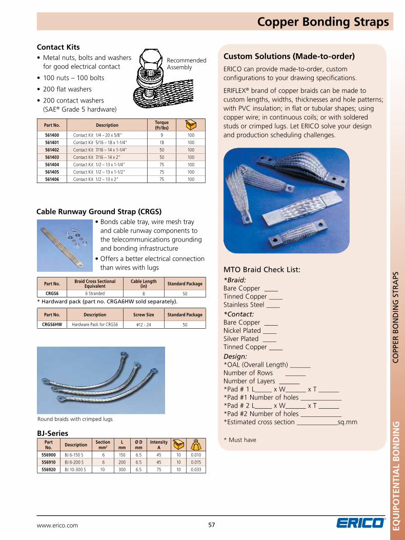
www.erico.com 57
Round braids with crimped lugs
Contact Kits
Recommended Assembly
BJ-Series
•Metalnuts,boltsandwashers for good electrical contact
• 100nuts–100bolts
• 200flatwashers
• 200contactwashers (SAE® Grade 5 hardware)
Part No. Description Torque (ft/lbs)
561400 Contact Kit 1/4 – 20 x 5/8” 9 100
561401 Contact Kit 5/16 – 18 x 1-1/4” 18 100
561402 Contact Kit 7/16 – 14 x 1-1/4” 50 100
561403 Contact Kit 7/16 – 14 x 2” 50 100
561404 Contact Kit 1/2 – 13 x 1-1/4” 75 100
561405 Contact Kit 1/2 – 13 x 1-1/2” 75 100
561406 Contact Kit 1/2 – 13 x 2” 75 100
Part No. Description Section
mm2L
mmØ D mm
Intensity A
556900 BJ 6-150 S 6 150 6.5 45 10 0.010
556910 BJ 6-200 S 6 200 6.5 45 10 0.015
556920 BJ 10-300 S 10 300 6.5 75 10 0.033
Cable Runway Ground Strap (CRGS)•Bondscabletray,wiremeshtray
and cable runway components to the telecommunications grounding and bonding infrastructure
•Offersabetterelectricalconnectionthan wires with lugs
* Hardward pack (part no. CRGA6HW sold separately).
Part No. Braid Cross Sectional Equivalent
Cable Length (in) Standard Package
CRGS6 6 Stranded 8 50
Part No. Description Screw Size Standard Package
CRGS6HW Hardware Pack for CRGS6 #12 - 24 50
Copper Bonding Straps
EQu
IPO
TEN
TIA
L B
ON
DIN
GC
Opp
ER B
On
DIn
G S
TRA
pS
ERICO can provide made-to-order, custom configurations to your drawing specifications.
ERIFLEX® brand of copper braids can be made to custom lengths, widths, thicknesses and hole patterns; with PVC insulation; in flat or tubular shapes; using copper wire; in continuous coils; or with soldered studs or crimped lugs. Let ERICO solve your design and production scheduling challenges.
MTO Braid Check List:*Braid:Bare Copper ____Tinned Copper ____Stainless Steel ____ *Contact:Bare Copper ____Nickel Plated ____Silver Plated ____Tinned Copper ____Design:*OAL (Overall Length) ______Number of Rows ______Number of Layers ______*Pad # 1 L_____ x W______ x T ______*Pad #1 Number of holes ____________*Pad # 2 L_____ x W______ x T ______*Pad #2 Number of holes ____________*Estimated cross section ____________sq.mm
* Must have
Custom Solutions (Made-to-order)
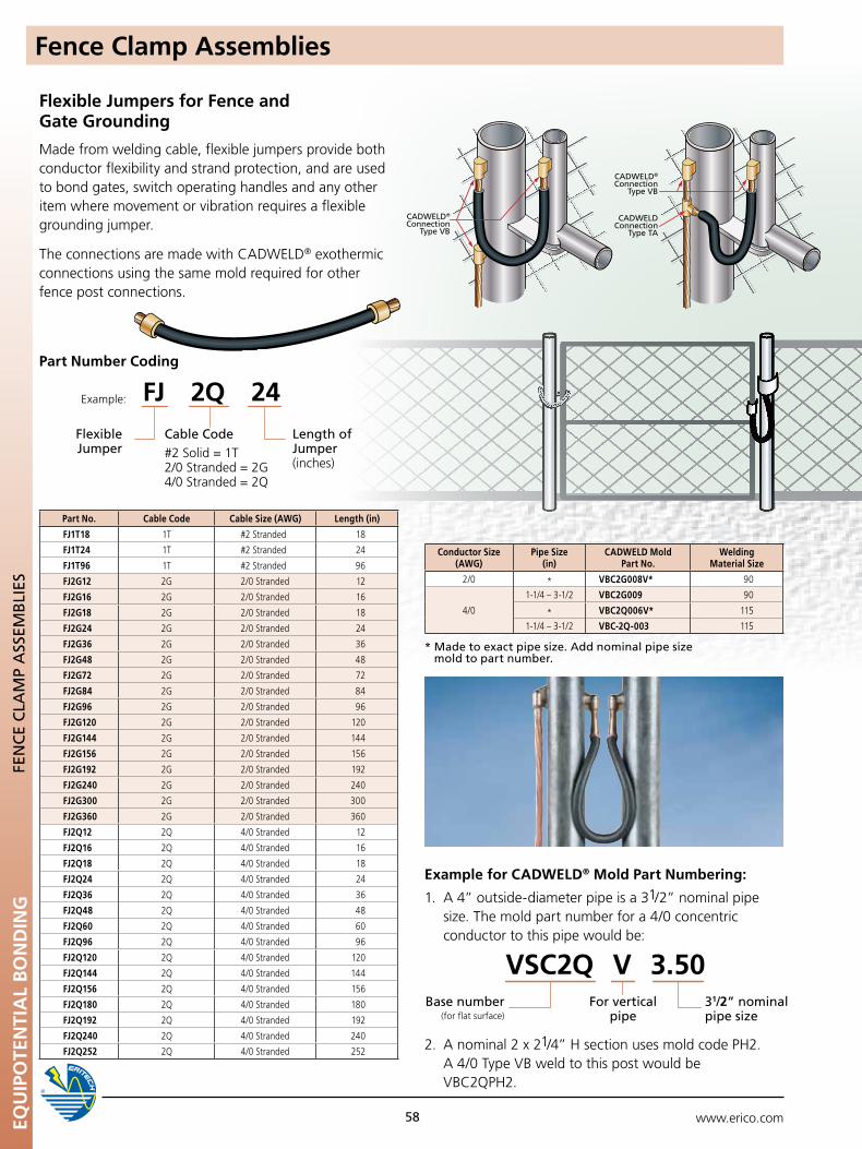
www.erico.comEQU
IPO
TEN
TIA
L B
ON
DIN
G
58
FEn
CE
CLA
Mp
ASS
EMB
LIES
Flexible Jumpers for Fence and Gate Grounding
Made from welding cable, flexible jumpers provide both conductor flexibility and strand protection, and are used to bond gates, switch operating handles and any other item where movement or vibration requires a flexible grounding jumper.
The connections are made with CADWELD® exothermic connections using the same mold required for other fence post connections.
CADWELD®
ConnectionType VB
CADWELD®
ConnectionType VB
CADWELDConnection
Type TA
CADWELD®
ConnectionType VB
CADWELD®
ConnectionType VB
CADWELDConnection
Type TA
Flexible Jumper
Part Number Coding
Example: FJ 2Q 24Cable Code#2 Solid = 1T2/0 Stranded = 2G4/0 Stranded = 2Q
Length of Jumper (inches)
Example for CADWELD® Mold Part Numbering:
Base number (for flat surface)
VSC2Q V 3.50For vertical
pipe31/2” nominal pipe size
1. A 4” outside-diameter pipe is a 31/2” nominal pipe size. The mold part number for a 4/0 concentric conductor to this pipe would be:
2. A nominal 2 x 21/4” H section uses mold code PH2. A 4/0 Type VB weld to this post would be VBC2QPH2.
Part No. Cable Code Cable Size (AWG) Length (in)
FJ1T18 1T #2 Stranded 18
FJ1T24 1T #2 Stranded 24
FJ1T96 1T #2 Stranded 96
FJ2G12 2G 2/0 Stranded 12
FJ2G16 2G 2/0 Stranded 16
FJ2G18 2G 2/0 Stranded 18
FJ2G24 2G 2/0 Stranded 24
FJ2G36 2G 2/0 Stranded 36
FJ2G48 2G 2/0 Stranded 48
FJ2G72 2G 2/0 Stranded 72
FJ2G84 2G 2/0 Stranded 84
FJ2G96 2G 2/0 Stranded 96
FJ2G120 2G 2/0 Stranded 120
FJ2G144 2G 2/0 Stranded 144
FJ2G156 2G 2/0 Stranded 156
FJ2G192 2G 2/0 Stranded 192
FJ2G240 2G 2/0 Stranded 240
FJ2G300 2G 2/0 Stranded 300
FJ2G360 2G 2/0 Stranded 360
FJ2Q12 2Q 4/0 Stranded 12
FJ2Q16 2Q 4/0 Stranded 16
FJ2Q18 2Q 4/0 Stranded 18
FJ2Q24 2Q 4/0 Stranded 24
FJ2Q36 2Q 4/0 Stranded 36
FJ2Q48 2Q 4/0 Stranded 48
FJ2Q60 2Q 4/0 Stranded 60
FJ2Q96 2Q 4/0 Stranded 96
FJ2Q120 2Q 4/0 Stranded 120
FJ2Q144 2Q 4/0 Stranded 144
FJ2Q156 2Q 4/0 Stranded 156
FJ2Q180 2Q 4/0 Stranded 180
FJ2Q192 2Q 4/0 Stranded 192
FJ2Q240 2Q 4/0 Stranded 240
FJ2Q252 2Q 4/0 Stranded 252
* Made to exact pipe size. Add nominal pipe size mold to part number.
Conductor Size (AWG)
Pipe Size (in)
CADWELD Mold Part No.
Welding Material Size
2/0 * VBC2G008V* 90
4/0
1-1/4 – 3-1/2 VBC2G009 90
* VBC2Q006V* 115
1-1/4 – 3-1/2 VBC-2Q-003 115
Fence Clamp Assemblies
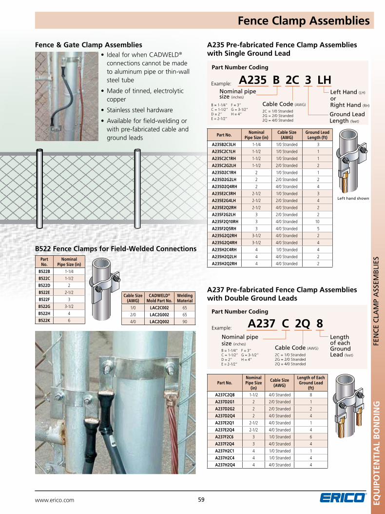
www.erico.com EQU
IPO
TEN
TIA
L B
ON
DIN
G
59
FEn
CE
CLA
Mp
ASS
EMB
LIES
Cable Code (AWG)
2C = 1/0 Stranded2G = 2/0 Stranded2Q = 4/0 Stranded
B = 1-1/4”C = 1-1/2”D = 2”E = 2-1/2”
F = 3”G = 3-1/2”H = 4”
nominal pipe size (inches)
Part Number Coding
A235 Pre-fabricated Fence Clamp Assemblies with Single Ground Lead
A235 B 2C 3 LHExample:
Ground Lead Length (feet)
Left Hand (LH) or Right Hand (RH)
Left hand shown
Part No. Nominal Pipe Size (in)
Cable Size (AWG)
Ground Lead Length (ft)
A235B2C3LH 1-1/4 1/0 Stranded 3
A235C2C1LH 1-1/2 1/0 Stranded 1
A235C2C1RH 1-1/2 1/0 Stranded 1
A235C2G2LH 1-1/2 2/0 Stranded 2
A235D2C1RH 2 1/0 Stranded 1
A235D2G2LH 2 2/0 Stranded 2
A235D2Q4RH 2 4/0 Stranded 4
A235E2C3RH 2-1/2 1/0 Stranded 3
A235E2G4LH 2-1/2 2/0 Stranded 4
A235E2Q2RH 2-1/2 4/0 Stranded 2
A235F2G2LH 3 2/0 Stranded 2
A235F2Q10RH 3 4/0 Stranded 10
A235F2Q5RH 3 4/0 Stranded 5
A235G2Q2RH 3-1/2 4/0 Stranded 2
A235G2Q4RH 3-1/2 4/0 Stranded 4
A235H2C4RH 4 1/0 Stranded 4
A235H2Q2LH 4 4/0 Stranded 2
A235H2Q2RH 4 4/0 Stranded 2
B522 Fence Clamps for Field-Welded Connections
Fence & Gate Clamp Assemblies• IdealforwhenCADWELD® connections cannot be made to aluminum pipe or thin-wall steel tube
• Madeoftinned,electrolyticcopper
• Stainlesssteelhardware
•Availableforfield-weldingor with pre-fabricated cable and ground leads
Part No.
Nominal Pipe Size (in)
B522B 1-1/4
B522C 1-1/2
B522D 2
B522E 2-1/2
B522F 3
B522G 3-1/2
B522H 4
B522K 6
Cable Size (AWG)
CADWELD® Mold Part No.
Welding Material
1/0 LAC2C002 65
2/0 LAC2G002 65
4/0 LAC2Q002 90
Cable Code (AWG)
2C = 1/0 Stranded2G = 2/0 Stranded2Q = 4/0 Stranded
B = 1-1/4”C = 1-1/2”D = 2”E = 2-1/2”
F = 3”G = 3-1/2”H = 4”
nominal pipe size (inches)
Part Number Coding
A237 Pre-fabricated Fence Clamp Assemblies with Double Ground Leads
A237 C 2Q 8Example:
Length of each Ground Lead (feet)
Part No.Nominal Pipe Size
(in)
Cable Size (AWG)
Length of Each Ground Lead
(ft)
A237C2Q8 1-1/2 4/0 Stranded 8
A237D2G1 2 2/0 Stranded 1
A237D2G2 2 2/0 Stranded 2
A237D2Q4 2 4/0 Stranded 4
A237E2Q1 2-1/2 4/0 Stranded 1
A237E2Q4 2-1/2 4/0 Stranded 4
A237F2C6 3 1/0 Stranded 6
A237F2Q4 3 4/0 Stranded 4
A237H2C1 4 1/0 Stranded 1
A237H2C4 4 1/0 Stranded 4
A237H2Q4 4 4/0 Stranded 4
Fence Clamp Assemblies
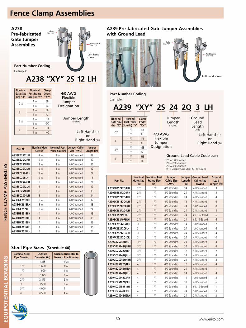
www.erico.comEQU
IPO
TEN
TIA
L B
ON
DIN
G
60
Gate(size “X”)
Post Frame(size “Y”)
Gate(size “X”)
Post Frame(size “Y”)
Gate(size “X”)
Post Frame(size “Y”)
Steel Pipe Sizes (Schedule 40)
A238 Pre-fabricated Gate Jumper Assemblies
Part Number Coding
A238 “XY” 2S 12 LHExample:
Jumper Length (inches)
Left Hand (LH) or
Right Hand (RH)
4/0 AWG Flexible Jumper
Designation
FEn
CE
CLA
Mp
ASS
EMB
LIES
A239 Pre-fabricated Gate Jumper Assemblies with Ground Lead
Part Number Coding
A239 “XY” 2S 24 2Q 3 LHExample:
Jumper Length
(inches)
Left Hand (LH) or
Right Hand (RH)
4/0 AWG Flexible Jumper
Designation
Gate(size “X”)
Post Frame(size “Y”)
Gate(size “X”)
Post Frame(size “Y”)
Gate(size “X”)
Post Frame(size “Y”)
Ground Lead
Length (feet)
Ground Lead Cable Code (AWG)
2C = 1/0 Stranded2G = 2/0 Stranded2Q = 4/0 Stranded9F = Copper-Clad Steel #9, 19-Strand
Left hand shown
Left hand shown
Part No. Nominal Gate Size (in)
Nominal Post Frame Size (in)
Jumper Cable Size (AWG)
Jumper Length (in)
A238EB2S12LH 2 1/2 1 1/4 4/0 Stranded 12
A238EB2S12RH 2 1/2 1 1/4 4/0 Stranded 12
A238EB2S18RH 2 1/2 1 1/4 4/0 Stranded 18
A238EC2S12LH 2 1/2 1 1/2 4/0 Stranded 12
A238EC2S24RH 2 1/2 1 1/2 4/0 Stranded 24
A238EC2S8LH 2 1/2 1 1/2 4/0 Stranded 8
A238FB2S24LH 3 1 1/4 4/0 Stranded 24
A238FC2S12LH 3 1 1/2 4/0 Stranded 12
A238FC2S18RH 3 1 1/2 4/0 Stranded 18
A238FC2S24LH 3 1 1/2 4/0 Stranded 24
A238GC2S12LH 3 1/2 1 1/2 4/0 Stranded 12
A238GC2S18RH 3 1/2 1 1/2 4/0 Stranded 18
A238GC2S24LH 3 1/2 1 1/2 4/0 Stranded 24
A238HB2S18LH 4 1 1/4 4/0 Stranded 18
A238HB2S18RH 4 1 1/4 4/0 Stranded 18
A238HC2S12LH 4 1 1/2 4/0 Stranded 12
A238HC2S15RH 4 1 1/2 4/0 Stranded 15
A238HC2S24LH 4 1 1/2 4/0 Stranded 24
Nominal Gate Size (in) “X”
Nominal Post Frame
Size (in) “Y”
Clamp Codes “XY”
2 1/21 1/4 EB
1 1/2 EC
31 1/4 FB
1 1/2 FC
3 1/21 1/4 GB
1 1/2 GC
41 1/4 HB
1 1/2 HC
Nominal Steel Pipe Size (in)
Outside Diameter (in)
Outside Diameter to Nearest Fraction (in)
1 1.315 1 5/16
1 1/4 1.660 1 5/8
1 1/2 1.900 1 7/8
2 2.375 2 3/8
2 1/2 2.875 2 7/8
3 3.500 3 1/2
3 1/2 4.000 4
4 4.500 4 1/2
Part No.Nominal Gate Size
(in)
Nominal Post Frame Size
(in)
Jumper Cable Size
(AWG)
Jumper Length
(in)
Ground Lead Cable Size
(AWG)
Ground Lead
Length (ft)
A239EB2S242Q3LH 2 1/2 1 1/4 4/0 Stranded 24 4/0 Stranded 3
A239EB2S242Q3RH 2 1/2 1 1/4 4/0 Stranded 24 4/0 Stranded 3
A239EB2S242Q4LH 2 1/2 1 1/4 4/0 Stranded 24 4/0 Stranded 4
A239EC2S182Q6LH 2 1/2 1 1/2 4/0 Stranded 18 4/0 Stranded 6
A239EC2S242C8RH 2 1/2 1 1/2 4/0 Stranded 24 1/0 Stranded 8
A239EC2S242G4LH 2 1/2 1 1/2 4/0 Stranded 24 2/0 Stranded 4
A239EC2S249F6LH 2 1/2 1 1/2 4/0 Stranded 24 #9, 19-Strand 6
A239EC2S249F6RH 2 1/2 1 1/2 4/0 Stranded 24 #9, 19-Strand 6
A239FC2S142C2RH 3 1 1/2 4/0 Stranded 14 1/0 Stranded 2
A239FC2S242C6LH 3 1 1/2 4/0 Stranded 24 1/0 Stranded 6
A239FC2S242G4RH 3 1 1/2 4/0 Stranded 24 2/0 Stranded 4
A239FC2S242Q10R 3 1 1/2 4/0 Stranded 24 4/0 Stranded 10
A239GB2S242Q4LH 3 1/2 1 1/4 4/0 Stranded 24 4/0 Stranded 4
A239GB2S242Q4RH 3 1/2 1 1/4 4/0 Stranded 24 4/0 Stranded 4
A239GC2S122Q2RH 3 1/2 1 1/2 4/0 Stranded 12 4/0 Stranded 2
A239GC2S242Q4LH 3 1/2 1 1/2 4/0 Stranded 24 4/0 Stranded 4
A239GC2S242Q4RH 3 1/2 1 1/2 4/0 Stranded 24 4/0 Stranded 4
A239HB2S122Q4LH 4 1 1/4 4/0 Stranded 12 4/0 Stranded 4
A239HB2S242Q1RH 4 1 1/4 4/0 Stranded 24 4/0 Stranded 1
A239HB2S242Q4LH 4 1 1/4 4/0 Stranded 24 4/0 Stranded 4
A239HC2S142C2RH 4 1 1/2 4/0 Stranded 14 1/0 Stranded 2
A239HC2S182Q6LH 4 1 1/2 4/0 Stranded 18 4/0 Stranded 6
A239HC2S189F1RH 4 1 1/2 4/0 Stranded 18 #9, 19-Strand 1
A239HC2S242C10L 4 1 1/2 4/0 Stranded 24 1/0 Stranded 10
A239HC2S242G2RH 4 1 1/2 4/0 Stranded 24 2/0 Stranded 2
Nominal Gate Size (in) “X”
Nominal Post Frame
Size (in) “Y”
Clamp Codes “XY”
2 1/21 1/4 EB
1 1/2 EC
31 1/4 FB
1 1/2 FC
3 1/21 1/4 GB
1 1/2 GC
41 1/4 HB
1 1/2 HC
Fence Clamp Assemblies
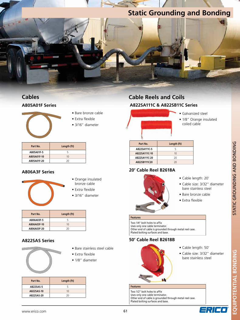
www.erico.com EQU
IPO
TEN
TIA
L B
ON
DIN
G
61
Cables Cable Reels and CoilsA805A01F Series
A806A3F Series
A822SAS Series
A822SA111C & A822SB11C Series
20’ Cable Reel B2618A
50’ Cable Reel B2618BST
ATI
C G
RO
un
DIn
G A
nD
BO
nD
InG
Part No. Length (ft)
A805A01F-5 5
A805A01F-10 10
A805A01F-20 20
Part No. Length (ft)
A806A03F-5 5
A806A03F-10 10
A806A03F-20 20
Part No. Length (ft)
A822SAS-5 5
A822SAS-10 10
A822SAS-20 20
Part No. Length (ft)
A822SA111C-5 5
A822SA111C-10 10
A822SA111C-20 20
A822SB111C20 20
Features
Two 1/4” bolt holes to affixuses only one cable terminator. Other end of cable is grounded through metal reel case.plated bolting surfaces and base.
Features
Two 1/2” bolt holes to affixuses only one cable terminator. Other end of cable is grounded through metal reel case.plated bolting surfaces and base.
•Barebronzecable
•Extraflexible
•3/16”diameter
•Orangeinsulatedbronze cable
•Extraflexible
•3/16”diameter
•Barestainlesssteelcable
•Extraflexible
•1/8”diameter
•Galvanizedsteel
•1/8”Orangeinsulated coiled cable
•Cablelength:20’
•Cablesize:3/32”diameterbare stainless steel
•Barebronzecable
•Extraflexible
•Cablelength:50’
•Cablesize:3/32”diameterbare stainless steel
Static Grounding and Bonding
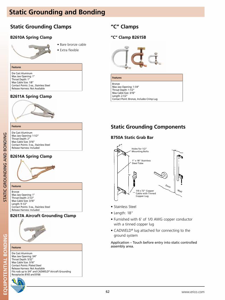
www.erico.comEQU
IPO
TEN
TIA
L B
ON
DIN
G
62
STA
TIC
GR
Ou
nD
InG
An
D B
On
DIn
G
Static Grounding and Bonding
Static Grounding Clamps “C” Clamps
Static Grounding Components
“C” Clamp B2615B
B750A Static Grab Bar
B2611A Spring Clamp
B2614A Spring Clamp
B2617A Aircraft Grounding Clamp
•Barebronzecable
•Extraflexible
Features
Die Cast AluminumMax Jaw Opening: 1”Throat Depth: 1”Max Cable Size: 1/8”Contact points: 2 ea., Stainless SteelRelease Harness: not Available
Features
BronzeMax Jaw Opening: 1-1/4”Throat Depth: 1-1/2”Max Cable Size: 3/16”Length: 2-1/2”Contact point: Bronze, Includes Crimp Lug
Features
Die Cast AluminumMax Jaw Opening: 1-1/2”Throat Depth: 2”Max Cable Size: 3/16”Contact points: 3 ea., Stainless SteelRelease Harness: Included
Features
BronzeMax Jaw Opening: 1”Throat Depth: 2-1/2”Max Cable Size: 3/16”Length: 9-1/2”Contact points: 3 ea., Stainless SteelRelease Harness: Included
Features
Die Cast AluminumMax Jaw Opening: 3/4”Throat Depth: 5/32”Max Cable Size: 3/16”Contact points: plated SteelRelease Harness: not AvailableFits rods up to 3/4” and CADWELD® Aircraft Grounding Receptacles B165 and B166
•StainlessSteel
•Length:18”
•Furnishedwith6’of1/0AWGcopperconductorwith a tinned copper lug
•CADWELD® lug attached for connecting to the ground system
Application – Touch before entry into static controlled assembly area.
Holes for 1/2” Mounting Bolts
1” x 18” Stainless Steel Tube
1/0 x 72” Copper Cable with Tinned Copper Lug
DoorWall
B2610A Spring Clamp

www.erico.com 63 GR
Ou
ND
RES
ISTA
NC
E TE
STER
S
Ground Resistance Testers
cable reels
pg 61
pg 61
clamp on probe
resistance tester
ground tester kits
pg 60
pg 61
Ground tester
pg 60
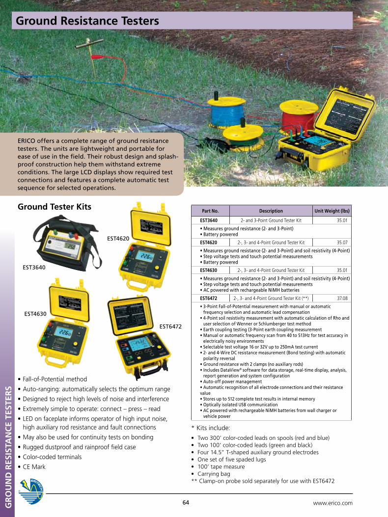
www.erico.com64
Ground Tester Kits
* Kits include: • Two300’color-codedleadsonspools(redandblue) • Two100’color-codedleads(greenandblack) • Four14.5”T-shapedauxiliarygroundelectrodes • Onesetoffivespadedlugs • 100’tapemeasure • Carryingbag ** Clamp-on probe sold separately for use with EST6472
•Fall-of-Potentialmethod
•Auto-ranging:automaticallyselectstheoptimumrange
•Designedtorejecthighlevelsofnoiseandinterference
•Extremelysimpletooperate:connect–press–read
•LEDonfaceplateinformsoperatorofhighinputnoise,high auxiliary rod resistance and fault connections
•Mayalsobeusedforcontinuitytestsonbonding
•Ruggeddustproofandrainprooffieldcase
•Color-codedterminals
•CEMark
EST3640
EST4620
EST4630
EST6472
Part No. Description unit Weight (lbs)
EST3640 2- and 3-Point Ground Tester Kit 35.01
•Measuresgroundresistance(2-and3-Point)•Batterypowered
EST4620 2-, 3- and 4-Point Ground Tester Kit 35.07
•Measuresgroundresistance(2-and3-Point)andsoilresistivity(4-Point)•Stepvoltagetestsandtouchpotentialmeasurements•Batterypowered
EST4630 2-, 3- and 4-Point Ground Tester Kit 35.01
•Measuresgroundresistance(2-and3-Point)andsoilresistivity(4-Point)•Stepvoltagetestsandtouchpotentialmeasurements•ACpoweredwithrechargeableNiMHbatteries
EST6472 2-, 3- and 4-Point Ground Tester Kit (**) 37.08
•3-PointFall-of-Potentialmeasurementwithmanualorautomaticfrequency selection and automatic lead compensation
•4-PointsoilresistivitymeasurementwithautomaticcalculationofRhoanduser selection of Wenner or Schlumberger test method
•Earthcouplingtesting(3-Pointearthcouplingmeasurement•Manualorautomaticfrequencyscanfrom40to513Hzfortestaccuracyin
electrically noisy environments•Selectabletestvoltage16or32Vupto250mAtestcurrent•2-and4-WireDCresistancemeasurement(Bondtesting)withautomatic
polarity reversal•Groundresistancewith2clamps(noauxiliaryrods)•IncludesDataView® software for data storage, real-time display, analysis,
report generation and system configuration•Auto-offpowermanagement•Automaticrecognitionofallelectrodeconnectionsandtheirresistancevalue•Storesupto512completetestresultsininternalmemory•OpticallyisolatedUSBcommunication•ACpoweredwithrechargeableNiMHbatteriesfromwallchargeror
vehicle power
Ground Resistance TestersG
RO
uN
D R
ESIS
TAN
CE
TEST
ERS
ERICO offers a complete range of ground resistance testers. The units are lightweight and portable for ease of use in the field. Their robust design and splash-proof construction help them withstand extreme conditions. The large LCD displays show required test connections and features a complete automatic test sequence for selected operations.
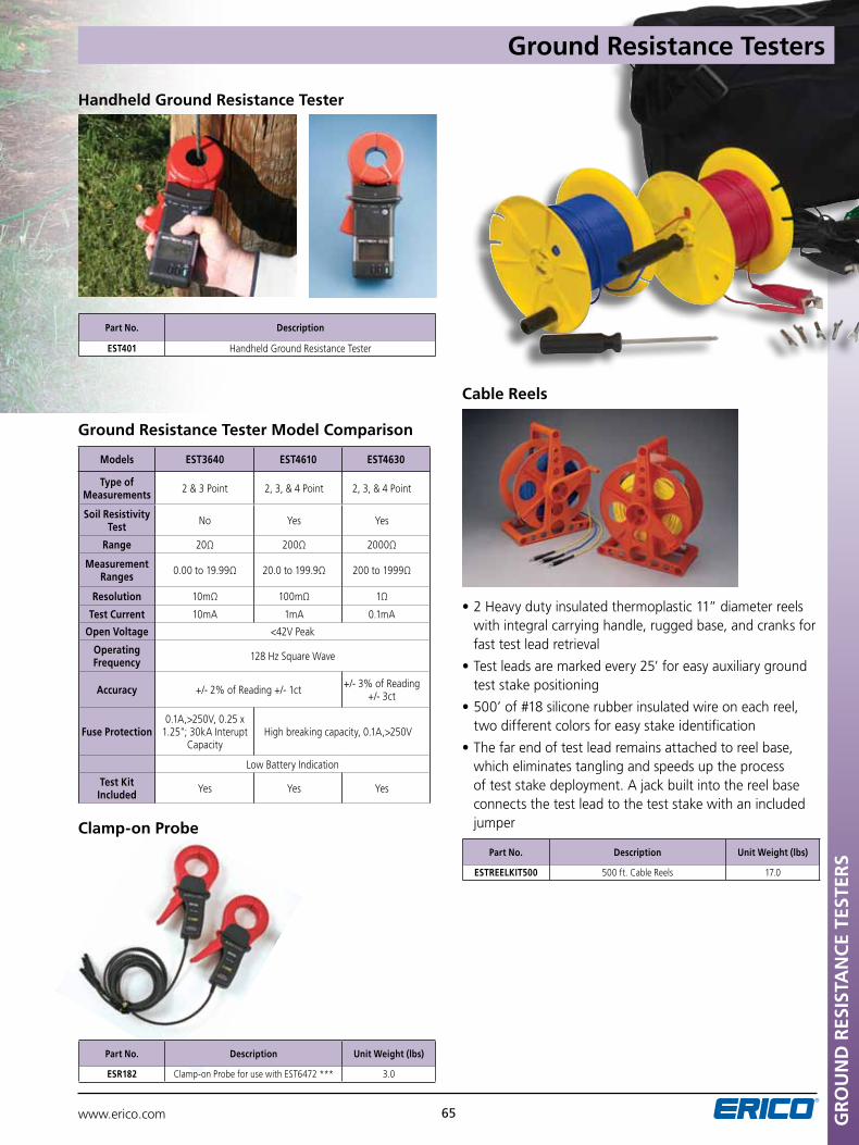
www.erico.com 65 GR
Ou
ND
RES
ISTA
NC
E TE
STER
S
Handheld Ground Resistance Tester
Part No. Description
EST401 Handheld Ground Resistance Tester
Cable Reels
•2Heavydutyinsulatedthermoplastic11”diameterreelswith integral carrying handle, rugged base, and cranks for fast test lead retrieval
•Testleadsaremarkedevery25’foreasyauxiliarygroundtest stake positioning
•500’of#18siliconerubberinsulatedwireoneachreel,two different colors for easy stake identification
•Thefarendoftestleadremainsattachedtoreelbase,which eliminates tangling and speeds up the process of test stake deployment. A jack built into the reel base connects the test lead to the test stake with an included jumper
Part No. Description unit Weight (lbs)
ESTREELKIT500 500 ft. Cable Reels 17.0
Part No. Description unit Weight (lbs)
ESR182 Clamp-on Probe for use with EST6472 *** 3.0
Clamp-on Probe
Ground Resistance Tester Model Comparison
Models EST3640 EST4610 EST4630
Type of Measurements 2&3Point 2,3,&4Point 2,3,&4Point
Soil Resistivity Test No Yes Yes
Range 20Ω 200Ω 2000Ω
Measurement Ranges 0.00 to 19.99Ω 20.0 to 199.9Ω 200 to 1999Ω
Resolution 10mΩ 100mΩ 1Ω
Test Current 10mA 1mA 0.1mA
Open Voltage <42V Peak
Operating Frequency 128 Hz Square Wave
Accuracy +/- 2% of Reading +/- 1ct +/- 3% of Reading +/- 3ct
Fuse Protection0.1A,>250V, 0.25 x
1.25"; 30kA Interupt Capacity
High breaking capacity, 0.1A,>250V
Low Battery Indication
Test Kit Included Yes Yes Yes
Ground Resistance Testers
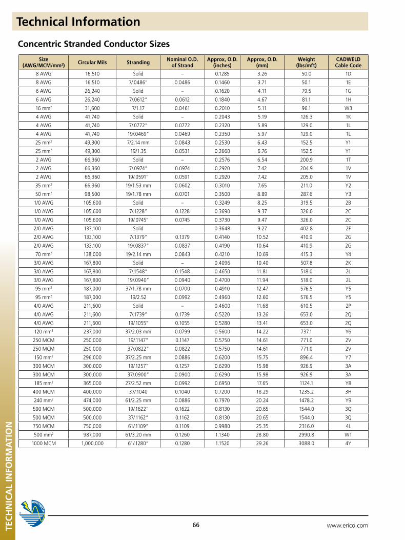
www.erico.com66TEC
HN
ICA
L IN
FOR
MA
TIO
N
Technical Information
Size (AWG/MCM/mm2) Circular Mils Stranding Nominal O.D.
of StrandApprox, O.D.
(inches)Approx, O.D.
(mm)Weight
(lbs/mft)CADWELD Cable Code
8 AWG 16,510 Solid – 0.1285 3.26 50.0 1D
8 AWG 16,510 7/.0486” 0.0486 0.1460 3.71 50.1 1E
6 AWG 26,240 Solid – 0.1620 4.11 79.5 1G
6 AWG 26,240 7/.0612” 0.0612 0.1840 4.67 81.1 1H
16 mm2 31,600 7/1.17 0.0461 0.2010 5.11 96.1 W3
4 AWG 41.740 Solid – 0.2043 5.19 126.3 1K
4 AWG 41,740 7/.0772” 0.0772 0.2320 5.89 129.0 1L
4 AWG 41,740 19/.0469” 0.0469 0.2350 5.97 129.0 1L
25 mm2 49,300 7/2.14 mm 0.0843 0.2530 6.43 152.5 Y1
25 mm2 49,300 19/1.35 0.0531 0.2660 6.76 152.5 Y1
2 AWG 66,360 Solid – 0.2576 6.54 200.9 1T
2 AWG 66,360 7/.0974” 0.0974 0.2920 7.42 204.9 1V
2 AWG 66,360 19/.0591” 0.0591 0.2920 7.42 205.0 1V
35 mm2 66,360 19/1.53 mm 0.0602 0.3010 7.65 211.0 Y2
50 mm2 98,500 19/1.78 mm 0.0701 0.3500 8.89 287.6 Y3
1/0 AWG 105,600 Solid – 0.3249 8.25 319.5 2B
1/0 AWG 105,600 7/.1228” 0.1228 0.3690 9.37 326.0 2C
1/0 AWG 105,600 19/.0745” 0.0745 0.3730 9.47 326.0 2C
2/0 AWG 133,100 Solid – 0.3648 9.27 402.8 2F
2/0 AWG 133,100 7/.1379” 0.1379 0.4140 10.52 410.9 2G
2/0 AWG 133,100 19/.0837” 0.0837 0.4190 10.64 410.9 2G
70 mm2 138,000 19/2.14 mm 0.0843 0.4210 10.69 415.3 Y4
3/0 AWG 167,800 Solid – 0.4096 10.40 507.8 2K
3/0 AWG 167,800 7/.1548” 0.1548 0.4650 11.81 518.0 2L
3/0 AWG 167,800 19/.0940” 0.0940 0.4700 11.94 518.0 2L
95 mm2 187,000 37/1.78 mm 0.0700 0.4910 12.47 576.5 Y5
95 mm2 187,000 19/2.52 0.0992 0.4960 12.60 576.5 Y5
4/0 AWG 211,600 Solid – 0.4600 11.68 610.5 2P
4/0 AWG 211,600 7/.1739” 0.1739 0.5220 13.26 653.0 2Q
4/0 AWG 211,600 19/.1055” 0.1055 0.5280 13.41 653.0 2Q
120 mm2 237,000 37/2.03 mm 0.0799 0.5600 14.22 737.1 Y6
250 MCM 250,000 19/.1147” 0.1147 0.5750 14.61 771.0 2V
250 MCM 250,000 37/.0822” 0.0822 0.5750 14.61 771.0 2V
150 mm2 296,000 37/2.25 mm 0.0886 0.6200 15.75 896.4 Y7
300 MCM 300,000 19/.1257” 0.1257 0.6290 15.98 926.9 3A
300 MCM 300,000 37/.0900” 0.0900 0.6290 15.98 926.9 3A
185 mm2 365,000 27/2.52 mm 0.0992 0.6950 17.65 1124.1 Y8
400 MCM 400,000 37/.1040 0.1040 0.7200 18.29 1235.2 3H
240 mm2 474,000 61/2.25 mm 0.0886 0.7970 20.24 1478.2 Y9
500 MCM 500,000 19/.1622” 0.1622 0.8130 20.65 1544.0 3Q
500 MCM 500,000 37/.1162” 0.1162 0.8130 20.65 1544.0 3Q
750 MCM 750,000 61/.1109” 0.1109 0.9980 25.35 2316.0 4L
500 mm2 987,000 61/3.20 mm 0.1260 1.1340 28.80 2990.8 W1
1000 MCM 1,000,000 61/.1280” 0.1280 1.1520 29.26 3088.0 4Y
Concentric Stranded Conductor Sizes
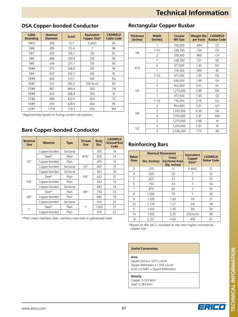
www.erico.com 67 TEC
HN
ICA
L IN
FOR
MA
TIO
N
Technical Information
Cable Stranding
Nominal Diameter kcmil Equivalent
Copper Size*CADWELD Cable Code
7/#10 .306 72.7 3 AWG 9A
7/#8 .385 115.6 1 9B
7/#7 .433 145.7 1/0 9C
7/#6 .486 183.8 2/0 9D
7/#5 .546 231.7 3/0 9E
19/#9 .572 248.8 3/0 9F
7/#4 .613 292.2 4/0 9L
19/#8 .642 313.7 4/0 9G
19/#7 .721 395.5 250 Kcmil 9H
37/#9 .801 484.4 300 7W
19/#6 .810 498.8 350 9J
37/#8 .899 610.9 400 7V
19/#5 .910 628.9 450 9K
37/#7 1.010 770.3 500 9M
Nominal Size Material Type Thread
SizeBody Dia.
CADWELD Ground Rod
Code
1/2”
Copper-bonded Sectional
9/16”
.505 14
Steel* Plain .500 14
Copper-bonded Plain .475 15
Copper-bonded Sectional 1/2” .447 13
Copper-bonded Sectional
5/8”
.563 16
5/8”
Steel* Plain .625 31
Copper-bonded Plain .563 16
Copper-bonded Sectional
3/4”
.682 18
3/4”
Steel* Plain .750 33
Copper-bonded Plain .682 18
Copper-bonded Sectional
1”
.914 22
1”Steel* Plain 1.000 37
Copper-bonded Plain .914 22
Thickness (inches)
Width (inches)
Circular Mil Size
Weight (lbs per foot)
CADWELD Busbar Code
1 159,200 .484 CE
1/81-1/2 238,700 .726 CG
2 318,300 .969 CH
3/16
1 238,700 .727 DE
2 477,500 1.45 DH
1 318,300 .969 EE
1-1/2 477,500 1.45 EG
1/4
2 636,600 1.94 EH
3 954,900 2.91 EK
4 1,273,000 3.88 EM
1 477,500 1.45 GE
1-1/2 716,200 2.18 GG
3/8
2 954,900 2.91 GH
3 1,432,000 4.36 GK
4 1,910,000 5.81 GM
2 1,273,000 3.88 JH
1/23 1,910,000 5.81 JK
4 2,546,000 7.75 JM
useful Conversions
Area Square Inches x 1273 = kcmil Square Millimeters x 1.974 = kcmil kcmil x 0.5067 = Square Millimeters
Density Copper: 0.323 lb/in3
Steel: 0.283 lb/in3
Rebar Sizes
Nominal Dimensions Equivalent Copper Sizes*
CADWELD Rebar CodeDia. (inches)
Cross-Secitonal Area
(Sq. inches)3 .375 .11 9 AWG 51
4 .500 .20 7 52
5 .625 .31 5 53
6 .750 .44 3 54
7 .875 .60 2 55
8 1.000 .79 1 56
9 1.128 1.00 1/0 57
10 1.270 1.27 2/0 58
11 1.410 1.56 3/0 59
14 1.693 2.25 250 kcmil 60
18 2.257 4.00 450 61
DSA Copper-bonded Conductor
Reinforcing Bars
Bare Copper-bonded Conductor
Rectangular Copper Busbar
*Approximate based on fusing current calculations
*Plain steel, stainless steel, stainless clad rods or galvanized steel.
* Based on 8% IACS, rounded to the next higher commercial copper size.
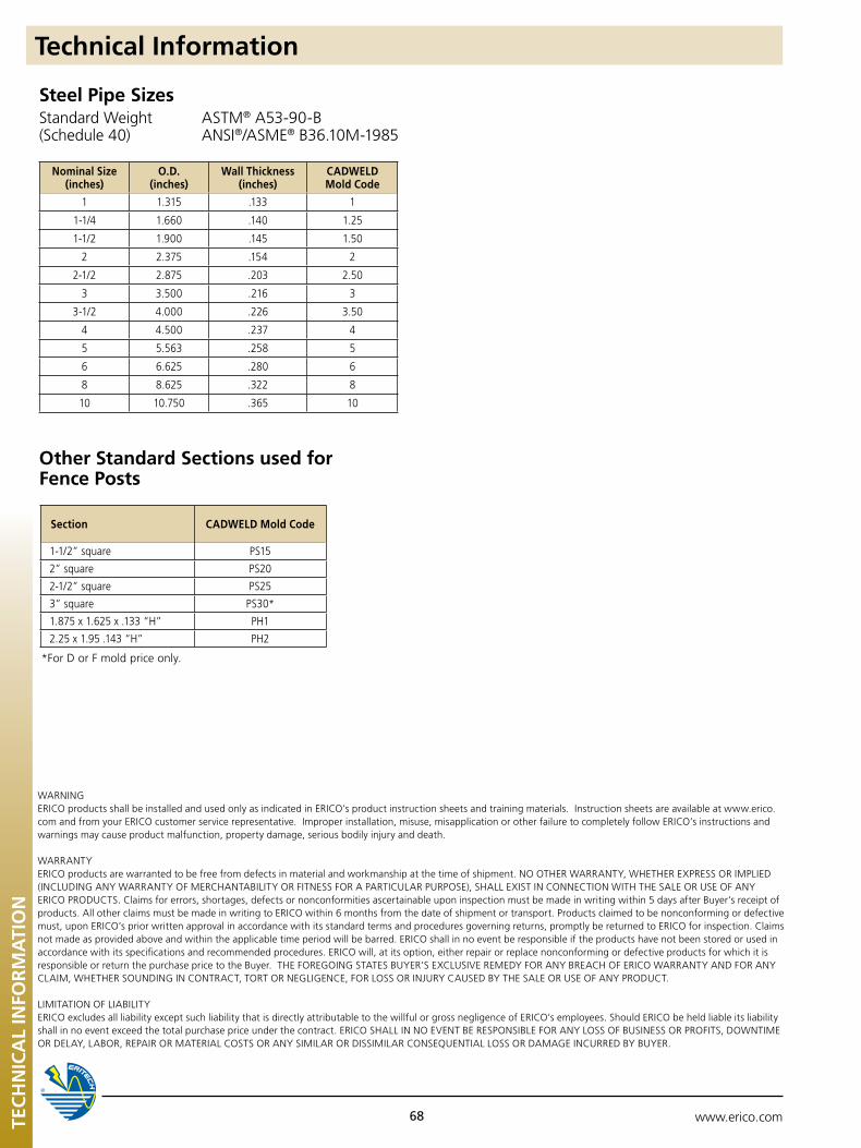
www.erico.com68TEC
HN
ICA
L IN
FOR
MA
TIO
N
Technical Information
Nominal Size (inches)
O.D.(inches)
Wall Thickness(inches)
CADWELD Mold Code
1 1.315 .133 1
1-1/4 1.660 .140 1.25
1-1/2 1.900 .145 1.50
2 2.375 .154 2
2-1/2 2.875 .203 2.50
3 3.500 .216 3
3-1/2 4.000 .226 3.50
4 4.500 .237 4
5 5.563 .258 5
6 6.625 .280 6
8 8.625 .322 8
10 10.750 .365 10
Steel Pipe Sizes
Other Standard Sections used for Fence Posts
Standard Weight(Schedule 40)
ASTM® A53-90-BANSI®/ASME® B36.10M-1985
WARNING ERICO products shall be installed and used only as indicated in ERICO’s product instruction sheets and training materials. Instruction sheets are available at www.erico.com and from your ERICO customer service representative. Improper installation, misuse, misapplication or other failure to completely follow ERICO’s instructions and warnings may cause product malfunction, property damage, serious bodily injury and death.
WARRANTYERICOproductsarewarrantedtobefreefromdefectsinmaterialandworkmanshipatthetimeofshipment.NOOTHERWARRANTY,WHETHEREXPRESSORIMPLIED(INCLUDINGANYWARRANTYOFMERCHANTABILITYORFITNESSFORAPARTICULARPURPOSE),SHALLEXISTINCONNECTIONWITHTHESALEORUSEOFANYERICO PRODUCTS. Claims for errors, shortages, defects or nonconformities ascertainable upon inspection must be made in writing within 5 days after Buyer’s receipt of products. All other claims must be made in writing to ERICO within 6 months from the date of shipment or transport. Products claimed to be nonconforming or defective must, upon ERICO’s prior written approval in accordance with its standard terms and procedures governing returns, promptly be returned to ERICO for inspection. Claims not made as provided above and within the applicable time period will be barred. ERICO shall in no event be responsible if the products have not been stored or used in accordance with its specifications and recommended procedures. ERICO will, at its option, either repair or replace nonconforming or defective products for which it is responsibleorreturnthepurchasepricetotheBuyer.THEFOREGOINGSTATESBUYER’SEXCLUSIVEREMEDYFORANYBREACHOFERICOWARRANTYANDFORANYCLAIM, WHETHER SOUNDING IN CONTRACT, TORT OR NEGLIGENCE, FOR LOSS OR INJURY CAUSED BY THE SALE OR USE OF ANY PRODUCT.
LIMITATION OF LIABILITYERICO excludes all liability except such liability that is directly attributable to the willful or gross negligence of ERICO’s employees. Should ERICO be held liable its liability shall in no event exceed the total purchase price under the contract. ERICO SHALL IN NO EVENT BE RESPONSIBLE FOR ANY LOSS OF BUSINESS OR PROFITS, DOWNTIME OR DELAY, LABOR, REPAIR OR MATERIAL COSTS OR ANY SIMILAR OR DISSIMILAR CONSEQUENTIAL LOSS OR DAMAGE INCURRED BY BUYER.
Section CADWELD Mold Code
1-1/2” square PS15
2” square PS20
2-1/2” square PS25
3” square PS30*
1.875 x 1.625 x .133 “H” PH1
2.25 x 1.95 .143 “H” PH2
*For D or F mold price only.
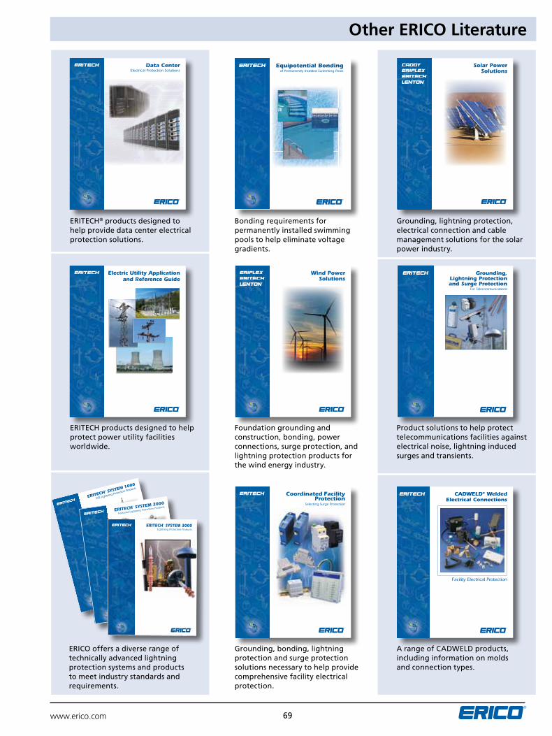
www.erico.com 69
Other ERICO Literature
Data CenterElectrical Protection Solutions
Electric Utility Application and Reference Guide
Equipotential Bondingof Permanently Installed Swimming Pools
Wind Power Solutions
Coordinated Facility Protection
Selecting Surge Protection
Solar Power Solutions
Grounding, Lightning Protectionand Surge Protection
For Telecommunications
CADWELD® WeldedElectrical Connections
Facility Electrical Protection
ERITECH® products designed to help provide data center electrical protection solutions.
ERITECH products designed to help protect power utility facilities worldwide.
ERICO offers a diverse range of technically advanced lightning protection systems and products to meet industry standards and requirements.
Bonding requirements for permanently installed swimming pools to help eliminate voltage gradients.
Foundation grounding and construction, bonding, power connections, surge protection, and lightning protection products for the wind energy industry.
Grounding, bonding, lightning protection and surge protection solutions necessary to help provide comprehensive facility electrical protection.
Grounding, lightning protection, electrical connection and cable management solutions for the solar power industry.
product solutions to help protect telecommunications facilities against electrical noise, lightning induced surges and transients.
A range of CADWELD products, including information on molds and connection types.
ERITECH® SYSTEM 1000
ESE Lightning Protection Products
ERITECH® SYSTEM 2000
Featured Lightning Protection Products
E1564LT09WWEN_2b.indd 1
11/22/10 11:50:58 AM
ERITECH® SYSTEM 3000Lightning Protection Products

www.erico.com
E1081C-NAEN E590CT12nAEn 75M0612Copyright ©2000, 2006, 2007, 2009, 2011, 2012 ERICO International Corporation. All rights reserved.CADDY, CADWELD, CRITEC, ERICO, ERIFLEX, ERITECH, and LEnTOn are registered trademarks of ERICO International Corporation.
ANSI is a registered trademark of the American National Standards Institute. ASME is a registerd trademark of the American Society of Mechanical Engineers. ASTM is a registerd trademark of American Society for Testing and Materials. BICSI is a registered trademark of BICSI, Inc. CSA is a registered trademark of The Canadian Standards Association Int’l. cULus is a registered trademark of Underwriters Laboratories, Inc. DataView is a registered trademark of Chauvin Arnoux, Inc. EIA is a registered service mark of the Electronic Industries Alliance. IEEE is a registered trademark of The Institute of Electrical and Electronics Engineers, Inc. NEC is a registered trademark of, and National Electrical Code (NEC) standard is a copyright of the National Fire Protection Association. NEMA is a registered trademark of the National Electrical Manufacturers Association. NFGC is a registered trademark of, and National Fuel Gas Code (NFGC) standard is a copyright of the National Fire Protection Association. NFPA is a registered trademark of the National Fire Protection Association. SAE is a registered trademark of SAE Intermational. TIA is a registered service mark of the Telecommunications Industry Association.
AuSTRALIAphone 1-800-263-508Fax 1-800-423-091
NORWAYphone 800-100-73Fax 800-100-66
HuNGARYphone 06-800-16538Fax +39-0244-386-107
CHINAphone +86-21-3430-4878 Fax +86-21-5831-8177
SWITZERLANDphone 0800-55-86-97Fax 0800-55-96-15
BELGIuMphone 0800-757-48Fax 0800-757-60
POLANDphone +48-71-349-04-60Fax +48-71-349-04-61
INDONESIAphone +62-21-575-0941Fax +62-21-575-0942
DENMARKphone 808-89-372Fax 808-89-373
THAILANDphone +66-2-267-5776Fax +66-2-636-6988
BRAZILphone +55-11-3623-4333Fax +55-11-3621-4066
SINGAPOREphone +65-6-268-3433Fax +65-6-268-1389
ITALYphone 800-870-938Fax 800-873-935
FRANCEphone 0-800-901-793Fax 0-800-902-024
uNITED ARAB EMIRATESphone +971-4-881-7250Fax +971-4-881-7270
CANADAphone +1-800-677-9089Fax +1-800-677-8131
SPAINphone 900-993-154Fax 900-807-333
MEXICOphone +52-55-5260-5991Fax +52-55-5260-3310
GERMANYphone 0-800-189-0272Fax 0-800-189-0274
uNITED KINGDOMphone 0808-2344-670Fax 0808-2344-676
CHILEphone +56-2-370-2908Fax +56-2-369-5657
SWEDENphone 020-790-908Fax 020-798-964
NETHERLANDSphone 0800-0200-135Fax 0800-0200-136
HONG KONGphone +852-2764-8808Fax +852-2764-4486
uNITED STATESphone 1-800-753-9221Fax +1-440-248-0723