erie railroad company - alternate wars
TRANSCRIPT

ERIE EMD F-3 Operating Manual
ERIE EMD F-3 Operating Manual Cover
For display similar to actual manual
| ------------------------------- set browser size to slightly larger than marks --------------------------- |
Reset browser to full size for large drawings
July 13, 1947
ERIE RAILROAD COMPANY
F3 DIESEL LOCOMOTIVES 800A-B-C to 806A-B-C
EMD E-760
OPERATING MANUAL
No. 2308
ELECTRO-MOTIVE DIVISION
GENERAL MOTORS CORPORATION LA GRANGE, ILLINOIS, U.S.A
file:///O|/rrff/manual/err-s0.html (1 of 8)10/2/2011 3:23:50 PM

ERIE EMD F-3 Operating Manual
INTRODUCTION
The purpose of this manual is to provide the engineer and fireman with information essential to the efficient and economical operation of the Diesel passenger locomotive.
The manual is divided into sections. The numeral in heavy type at the top corner of each page is the section number. Section 0 contains an index to the manual, an index to plates and a page of general data. Section 1 covers the general description, operating controls and instruments. Section 2 covers the operation of the locomotive. The
file:///O|/rrff/manual/err-s0.html (2 of 8)10/2/2011 3:23:50 PM

ERIE EMD F-3 Operating Manual
other sections, contain descriptions of the various "systems" and equipment throughout the locomotive. These sections are in loose-leaf form so that, as changes in procedures and equipment are made, revised pages may be inserted in the manual.
ELECTRO-MOTIVE DIVISION • GENERAL MOTORS CORPORATION MANUAL 2308 SECTION F3-0-1
ERIE RAILROAD COMPANY
F3 Diesel Locomotives
GENERAL DATA
Weight (fully loaded) "A" Unit (approx.) 230,000 lbs. "B" Unit (approx.) 230,000 lbs. Fuel Oil Capacity (per unit) 1200 gal. Lube Oil Capacity (per engine) 200 gal. Cooling Water Capacity "A" Unit "G" Valve Level 230 gal. "B" Unit "G" Valve Level 215 gal. Steam Generator Water Capacity "A" Unit 800 gal. "B" Unit 2000 gal. Sand Capacity (per unit) 16 cubic feet Gear Ratio 58/19 Maximum Permissible Speed 89 MPH Number of Drivers (per unit) 4 pair Wheel Diameter 40" Weight on Drivers 100% Truck Centers 30' 0" Truck Rigid Wheelbase 9' 0" Minimum Curve Radius 274' Center of Gravity above Rail (approx.) 63" Length: Between Coupler Pulling Faces "A" Unit 50' 8" "B" Unit 50' 0" Height: Over Horns 14'1 1/4" Width: Outside Grabirons 10'6 7/8"
TABLE OF CONTENTS
SECTION 0 -- General
file:///O|/rrff/manual/err-s0.html (3 of 8)10/2/2011 3:23:50 PM

ERIE EMD F-3 Operating Manual
General Data General Arrangement Dimensions, Drains and Fillers
SECTION 1 - Description
General Description Operating Controls Illustration-Engineer's Controls Engineer's Instruments Engine Controls
SECTION 2 - Locomotive Operation
Precautions Before Starting Engine Starting Engines After Layover Operation of Controls and Instruments Handling of Locomotive Precautions During Locomotive Operation Dynamic Brake (Used Only on Dynamic Brake Equipped Locomotives) Towing Locomotive Changing Operating Ends Locomotive Protective Devices Operation of F3 Units with FT or F2 Units Operation of Locomotives with Automatic Transition (Blue Insert)
SECTION 3 - Cooling System
Description Operation of Cooling System Illustration--Cab Heating System Illustration--Cooling and Lube Oil Systems
SECTION 4 - Lubricating Oil System
Description Operation of Lube Oil System
SECTION 5 - Fuel Oil System
Description Operation of Fuel Oil System Illustration-Fuel Oil System
SECTION 6 - Electrical Equipment
Description and Function of Electrical Equipment Illustrations -- Electrical Equipment Automatic Transition (Blue Insert) Schematic Wiring Diagram
file:///O|/rrff/manual/err-s0.html (4 of 8)10/2/2011 3:23:50 PM

ERIE EMD F-3 Operating Manual
SECTION 7 - Air System
Description and Operation of Air System Schematic of Air System
SECTION 8 - Trucks and Miscellaneous Equipment
General Information Truck Removal and Locomotive Lifting Diagram
SECTION 9 - Trouble Shooting
SECTION 10-Steam Generator
❍ General Arrangement - "A" Unit - Front ❍ General Arrangement - "A" Unit - Side ❍ General Arrangement - "A" Unit - Top, Internal ❍ General Arrangement - "A" Unit - Side, Internal ❍ General Arrangement - "B" Unit - Front ❍ General Arrangement - "B" Unit - Side ❍ General Arrangement - "B" Unit - Top, Internal ❍ General Arrangement - "B" Unit - Side, Internal ❍ Dimensions, Drains and Fillers - "A" Unit ❍ Dimensions, Drains and Fillers - "B" Unit
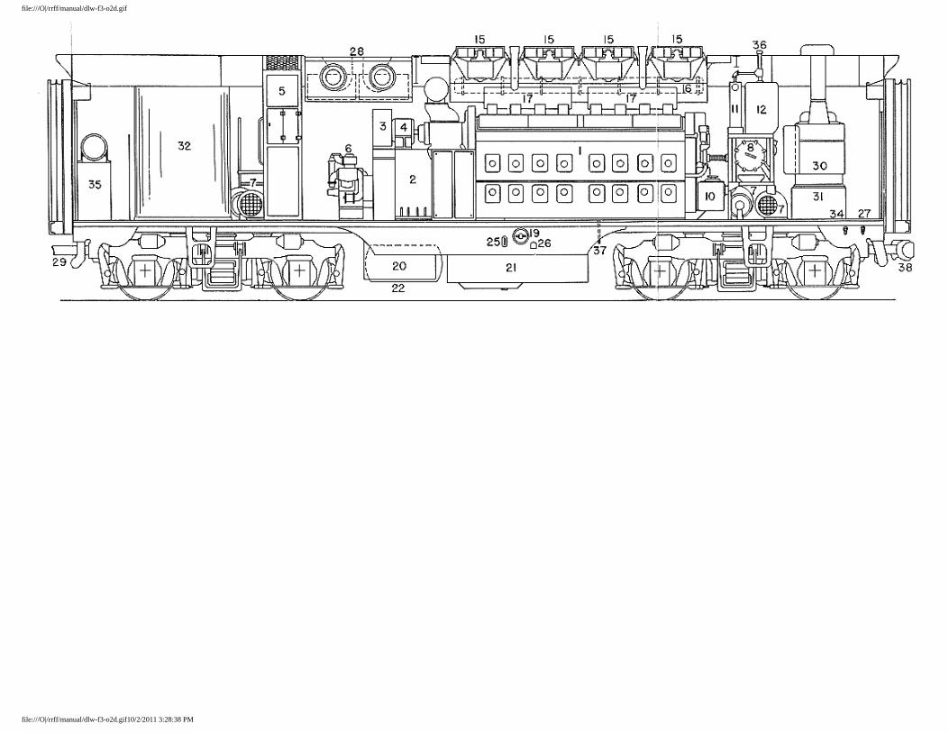
General Arrangement - "A" Unit
1. Model 16-567B Engine 16. Lube Oil Filer 30. Main Air Reservoir
2. Main Generator and Alternator 17. Lube Oil Cooler 31. Air Intake and Shutters
3. Generator Blower 18. Engine Cooling Water Tank
32. Steam Generator Water Filler (both sides)
4. Auxiliary Generator 19. Engine Control and Instrument Panel
33. Air Intake for Grids and Engine Room
5. Electrical Control Cabinet 20. Load Regulator 34. Fuel Tank Gauge
6. Air Compressor 21. Cooling Fan ;and Motor 35. Door
7. Traction Motor Blower 22. Radiator 36. Emergency Fuel Cutoff
8. Instrument Panel 23. Horn 37. Engine Water Filler (both sides)
9. Controller 24. Exhaust Manifold 38. Dynamic Brake Grids and Blowers
file:///O|/rrff/manual/err-s0.html (5 of 8)10/2/2011 3:23:50 PM

ERIE EMD F-3 Operating Manual
10. Speed Indicator 25. Sand Box 39. Steam Generator
11. Air Brake Valve 26. Fuel Filler (both sides) 40. Steam Generator Water Tank
12. Cab Heater 27. Headlight 41. Steam Generator Water Softener
13. Lube Oil Filter 28. Batteries 42. Coupler (Link)
14. Hand Brake 29. Fuel Tank 43. Toilet
15. Fuel Tank Vent with Flame Arrestor
44. Engine Sump Oil Drain (left side only)
45. Roof Water Filler (Engine)
NOTE: Steam Generator Model and Capacity at Customers Option. See General Data Page for Details.
General Arrangement - "B" Unit
1. Model 16-5678 Engine 16. Radiator 31. Steam Generator Water Tank (200 Gal. Tank with 1600 Lb. Stm. Gen.) (300 Gal. Tank with 300 Lb. Stm. Gen.)
2. Main Generator and Alternator 17. Exhaust Manifold
3. Generator Blower 18. Sand Box
4. Auxiliary Generator 19. Fuel Filler (both sides) 32. Steam Generator Water Tank for Large Steam Generators (1200 Gal.) 5. Electrical Control Cabinet 20. Batteries
6. Air Compressor 21. Fuel Tank 33. Steam Generator Water Tank Filler (both sides- 1200 Gal. Tank) 7. Traction Motor Blower 22. Min Air Reservoir
8. Lube Oil Filter 23. Air Intake and Shutters 34.
Steam Generator Water Tank Filler- (both sides- 200 and 300 Gal. Tanks only)
9. Fuel Tank Vent with Flame Arrestor
24. Air Intake for Grids and Engine Room
10. Lube Oil Filler 25. Fuel Tank Gauge 35. Air Brake Equipment
11. Lube Oil Cooler 26. Emergency Fuel Cutoff 36. Roof Water Filler (Engine)
12. Engine Cooling Water Tank 27. Engine Water Filler (both sides)
37. Engine Sump Oil Drain (left side only)
file:///O|/rrff/manual/err-s0.html (6 of 8)10/2/2011 3:23:50 PM

ERIE EMD F-3 Operating Manual
13. Engine Controf and Instrument Panel
28. D Dynamic Brake Grids and Blowers
38. Coupler (Type "E°)
14. Load Regulator 29. Coupler (Link) 39. Hand Brake
15. Cooling Fan and Motor 30. Steam Generator (1600 Lb. Capacity)
40. Steam Generator Water Softener
NOTE: Steam Generator Model ands Capacity at Customer's Option. See General Data Page for Details.
Dimensions, Drains and Fillers - "A" Unit
1. Pulling Face of Front Coupler.
2. Blocking Pads-both sides under pilot.
3. Sand Box Fillers-two on each side of car.
4. Jacking and Blocking Pads-both sides No. 1 bolster under carbody.
5. Battery Charging Receptacle-left side only.
6. Battery Box-both sides under carbody.
7. Engine Air Box Drain-both sides under carbody, valves at each side of engine under oil pan handhole covers No. 7 and 15.
8. Fuel Tank-under carbody.
9. Fuel Tank Water Drain Valve-both sides in tank sump.
10. Fuel Tank Sump Drain Plug-in tank sump.
11. Fuel Gauge-both sides in side skirt.
12. Fuel Filler-both sides in side skirt.
13. Fuel Tank Drain Plug-in bottom of tank sump.
14. Engine Sump Oil Drain-left side, valve and drain under carbody.
15. Engine Water Drain-under carbody,valve inside carbody.
16. Jacking and Blocking Pads-both sides No. 2 bolster under carbody.
17. Engine Oil Strainer Drain-left side under carbody, valve inside carbody.
18. Engine Water Filler-both sides under carbody at rear of car.
19. Steam Generator Water Tank Filler (200 and 300 gal. tanks)-both sides under carbody at rear of car.
20. Blocking Pads-both sides under carbody at rear of car.
21. Engine Roof Water Filler-on roof of car above engine cooling water tank.
Dimensions, Drains and Fillers - "B" Unit
1. Blocking Pads-both sides under carbody at front of car.
file:///O|/rrff/manual/err-s0.html (7 of 8)10/2/2011 3:23:50 PM

ERIE EMD F-3 Operating Manual
2. Sand Box Fillers-two on each side of car.
3. Jacking and Blocking Pads-both sides No. 1 bolster under carbody.
4. Battery Charging Receptacle-left side only.
5. Steam Generator Water Tank Filler (1200 gal. tank)both sides.
6. Battery Box-both sides under carbody.
7. Engine Air Box Drain-both sides under carbody, valves at each side of engine under oil pan handhole covers No. 7 and 15.
8. Fuel Tank-under carbody.
9. Fuel Tank Water Drain Valve-both sides in tank sump.
10. Fuel Tank Sump Drain Plug-in tank sump.
11. Fuel Gauge-both sides in side skirt.
12. Fuel Filler-both sides in side skirt.
13. Fuel Tank Drain Plug-in bottom of tank sump.
14. Engine Sump Oil Drain-left side, valve and drain under carbody.
15. Engine Water Drain-under carbody,valve inside carbody.
16. Jacking and Blocking Pads-both sides No. 2 bolster under carbody.
17. Engine Oil Strainer Drain-left side under carbody, valve inside carbody.
18. Engine Water Filler-both sides under carbody at rear of car.
19. Steam Generator Water Tank Filler (200 and 300 gal. tanks)-both sides under carbody at rear of car.
20. Blocking Pads-both sides under carbody at rear of car.
21. Engine Roof Water Filler-on roof of car above engine cooling water tank.
22. Pulling Face of Rear Coupler.
file:///O|/rrff/manual/err-s0.html (8 of 8)10/2/2011 3:23:50 PM

file:///O|/rrff/manual/dlw-f3-o1a.gif
file:///O|/rrff/manual/dlw-f3-o1a.gif10/2/2011 3:26:56 PM

file:///O|/rrff/manual/dlw-f3-o1b.gif
file:///O|/rrff/manual/dlw-f3-o1b.gif10/2/2011 3:27:12 PM

file:///O|/rrff/manual/dlw-f3-o1c.gif
file:///O|/rrff/manual/dlw-f3-o1c.gif10/2/2011 3:27:22 PM

file:///O|/rrff/manual/dlw-f3-o1d.gif
file:///O|/rrff/manual/dlw-f3-o1d.gif10/2/2011 3:27:46 PM

file:///O|/rrff/manual/dlw-f3-o2a.gif
file:///O|/rrff/manual/dlw-f3-o2a.gif10/2/2011 3:28:03 PM

file:///O|/rrff/manual/dlw-f3-o2b.gif
file:///O|/rrff/manual/dlw-f3-o2b.gif10/2/2011 3:28:13 PM

file:///O|/rrff/manual/dlw-f3-o2c.gif
file:///O|/rrff/manual/dlw-f3-o2c.gif10/2/2011 3:28:28 PM
file:///O|/rrff/manual/dlw-f3-o2d.gif
file:///O|/rrff/manual/dlw-f3-o2d.gif10/2/2011 3:28:38 PM

file:///O|/rrff/manual/dlw-f3-o3c.gif
file:///O|/rrff/manual/dlw-f3-o3c.gif10/2/2011 3:29:00 PM

file:///O|/rrff/manual/dlw-f3-o4c.gif
file:///O|/rrff/manual/dlw-f3-o4c.gif10/2/2011 3:29:09 PM

F-3 Section One
ELECTRO-MOTIVE DIVISION • GENERAL MOTORS CORPORATION SECTION F3-1-2 DESCRIPTION
SECTION 1
GENERAL DESCRIPTION
The Model F3 locomotive consists of one or more units rated at 1500 HP each. The increased horsepower rating over previous models is obtained by use of the D-12, D-14 main generator. The units with the cab are known as "A" units, those without the cab as "B" units. Each unit has one 16-cylinder Diesel engine, a direct current generator, an A.C. alternator, and four traction motors. From each power plant the power is distributed to the traction motors which are mounted on the trucks. The traction motors are geared to the axle through spur gears. The units are electrically independent of each other except for certain low voltage wiring. All units have batteries and are independent of each other for this service.
The engines are "V" type with a 45° angle between banks and have a compression ratio of 16 to 1. Solid unit injection is employed, there being an injector centrally located in each cylinder head. The engines have a speed range of 275 to 800 RPM. Their speed is controlled by an electro-hydraulic governor which is operated from the engineer's throttle. This governor replaces the electro-pneumatic governor control used on FT and F2 locomotives. In this way, all engines in locomotives of two or more units are controlled simultaneously. Each notch on the engineer's throttle changes the engine speed approximately 75 RPM.
The engines are fully scavenging. Two blowers are mounted on each engine over the generator. The blowers force air into the space around the cylinders with a pressure approximately 3 to 5 pounds per square inch. At the lower end of its downward stroke, the piston uncovers a row of ports in the cylinder liner admitting this scavenging air to the cylinder. Thus the exhaust gases are expelled around the exhaust valves and a fresh charge of air is made available for the next working stroke.
The accompanying sketch serves to identify the cylinder locations, ends and sides of the engine, as they are referred to in this manual. The electro-hydraulic governor, water pumps, and lubricating oil pumps are mounted on the "FRONT END." The
file:///O|/rrff/manual/err-s1.html (1 of 10)10/2/2011 3:29:24 PM

F-3 Section One
blowers, oil separator and generator are mounted on the "REAR END."
Starting the engines is accomplished by pressing the engine "START" switch button located on the engine control and instrument panel. This switch energizes the starting contactors, closing the circuit from the batteries to the main generator. The main generator, then operating as a motor, cranks the engine.
The flow of current out of the generator is always in the same direction. Reversing the locomotive is accomplished by reversing the direction of current in the traction motor fields. Detailed descriptions of controls and instruments may be found in the following pages.
OPERATING CONTROLS
Controller
The controller (or control stand) contains the throttle lever, reverse lever, and transition lever. The throttle lever, by means of electric contacts, operates the electro-hydraulic governor controls, which control the speed of the engines through the engine governors. The reverse lever operates electric contacts which close a circuit energizing either the "forward" or "reverse" magnet valves on the reversers in the electrical control cabinets. There is no mechanical connection between the reverse lever and the reverser. The transition lever, through electric contacts, changes the traction motor circuits to obtain the desired locomotive tractive effort and speed.
file:///O|/rrff/manual/err-s1.html (2 of 10)10/2/2011 3:29:24 PM

F-3 Section One
The transition lever when moved to the right of the "OFF" position is used to control dynamic braking.
The levers on the controller are interlocked so that:
● 1. The reverse lever can be operated only with the transition lever in either No. 1 or "OFF" position and throttle at "IDLE."
● 2. The reverse lever can be removed from the controller only with the transition lever in "OFF" position and throttle at "IDLE."
● 3. The transition lever can be moved into dynamic braking only when the reverse lever is in "forward" position and throttle at "IDLE."
● 4. The throttle cannot be opened when the transition lever is in "OFF" or "dynamic braking" position. ● 5. The throttle can be moved to "STOP" with any position of transition or reverse levers. ● 6. The transition lever can be moved from 2 to 3 position or 3 to 2 position with the throttle in any one
of the 8 running positions. This differs from the previous F2 and FT locomotives.
Throttle Emergency Stop Button
A throttle emergency "STOP" button is located on the end of the throttle lever. Its purpose is to stop all the engines in the locomotive in case of an emergency. It is operated by pressing the button and pushing the throttle lever to beyond the "IDLE" position.
Instrument Panel
The instrument panel contains the following indicators and controls: brake cylinder and brake pipe air gauge, application pipe and suppression pipe air gauge, main reservoir and equalizing reservoir air gauge, wheel slip light, dynamic brake warning light, transition and load indicating meter, cab heater switch and the windshield wiper valve. A cab heater switch and windshield wiper valve are also located on the fireman's side of the cab.
Pneumatic Control Switch
This switch, generally referred to as the "PC" switch, is an airoperated electric switch located on the right side of the cab, below the window. The function of the switch is to reduce the power of the locomotive by reducing the speed of the engines to idle when certain air-brake applications take place. The switch incorporates a manual reset button which must be pulled out after the brakes have been released. For further information on "PC" switch, see Section 2, "Locomotive Protective Devices."
Air Brake Equipment
The No. 24 RL brake equipment is normally used on the F3 locomotives. The details of this equipment are specified by the railroad to meet their particular operating requirements and vary from road to road. The air brake gauges are located on the instrument panel in front of the engineer. For full description, see the manufacturer's instruction books covering this equipment.
In general, the cab equipment consists of the automatic brake valve, the independent brake valve and the K-2-A
file:///O|/rrff/manual/err-s1.html (3 of 10)10/2/2011 3:29:24 PM

F-3 Section One
Rotair valve, a manually operated valve having four positions and located to the right of the controller stand as shown in Figure 1- 1.
The automatic brake valve handle has six positions (release, running, first service, lap, service and emergency) and may be of the rigid or non-rigid type.
The non-rigid brake valve handle is removable in "Running" position. The rigid brake valve handle is pinned in this position when a double cab locomotive is being operated from the opposite end.
The non-rigid handle, when partially depressed, obtains the same results as holding down the deadman control foot pedal described below. Further downward movement of the handle operates a sanding bail for sand application. However, either or both of these features may be omitted if so specified by the railroad.
The brake valve also contains:
● 1. Brake Valve Cutout Cock, located on the filling piece portion when the handle is pointing forward ("Live" position), the brake valve is cut in.
● 2. Safety Control Cutout Cock on the service application portion. When the handle is in the "Out" position, all safety devices (deadman control, locomotive overspeed and train control, where used) are cut out. It is usually sealed in the "In" position for normal operation.
● 3. Full Release Selector Cock on the rotary valve seat portion. When the handle is moved away from the engineer, toward the letters "MR" cast on the block, air at main reservoir pressure is supplied to the chamber above the automatic rotary valve as in the No. 6 ET and No. 8 ET equipment. This provides maximum rate of brake pipe recharge when the brake valve is in release position but overcharging is possible. When the selector cock is moved to the FV position (handle pointing toward engineer), air at pressure controlled by a large capacity feed valve is supplied to the same chamber. With the selector cock handle in this position and the automatic brake valve handle in release position, brake pipe recharge is obtained at a rate which represents the maximum that is possible. First Service Cock on the filling piece portion. The cock cuts in or out the first service position of the automatic brake valve. When the handle is pointing toward the engineer,the first service position is cut in.
Independent Brake Valve
The S-40-F independent brake valve handle has two positions "Release" and "Full Application" with the "Application Zone" between the two positions. The brake valve is of the self lapping type which automatically laps off the flow of air when the applied pressure reaches the valve corresponding to the position of the brake valve handle in the application zone. Release of locomotive brakes during automatic application is obtained by depressing the brake valve handle in release position.
K-2-A Rotair Valve
The four positions of the K-2-A Rotair valve are "FRGHT," "FRGHT LAP," "PASS LAP" and "PASS." See "OPERATION" for handling of this valve.
Deadman Control Feature
file:///O|/rrff/manual/err-s1.html (4 of 10)10/2/2011 3:29:24 PM

F-3 Section One
The deadman foot pedal is located in front of the engineer's seat. It must be kept depressed at all times except when the locomotive is stopped and locomotive brakes are applied (30 lbs. or more brake cylinder pressure). On some locomotives railroads have specified that the automatic brake valve be equipped with the deadman feature. If so equipped, the automatic brake valve handle may be depressed until it contacts the bail and the pressure then released on the foot pedal. If both the foot pedal and the automatic brake valve handle are released at the same time, a full service application of the air brakes will result.
Sanding Valve
The sanding valve is operated by depressing the automatic brake valve handle upon the sanding bail. In some cases railroads have specified that the sanding feature in the automatic brake valve be omitted and a single-acting independent sanding valve be installed. This valve is operated by pulling the lever all the way back until it latches.
Due to the high tractive effort and even pulling power of the locomotive, it should not be necessary to use sand to start or stop a train except under extremely bad rail conditions, and then only sparingly, as sand is injurious to the moving parts of the trucks and traction motors.
Windshield Wiper Valves
The speed of the wipers is controlled independently by needle valves; one is located on the instrument panel and one on the panel on the fireman's side of the cab, which turn the wipers on and off. The wipers should not be run on a dry window, as dirt on the glass or blade will scratch the glass. The wiper blade should be replaced when the rubber becomes worn or hard.
Horn Valves
The horns are operated by air valves which are controlled by pullcords, the handles of which are readily accessible to the engineer. One horn is directed to the front of the train and the other to the rear of the train.
Locomotive Bell Valve
The locomotive signal bell is operated by an air valve located at the engineer's station. This bell should not be confused with the alarm bell which is an electrical device.
Cab Heater Switches
There are two three-speed switches for controlling the cab heater motors independently, as well as turning them on and off. One is located on the instrument panel and one on the panel on the fireman's side of the cab.
ENGINEER'S INSTRUMENTS
Control Push-Button Switch Box
file:///O|/rrff/manual/err-s1.html (5 of 10)10/2/2011 3:29:24 PM

F-3 Section One
The control push-button switch box, located above the cab window to the right of the engineer, contains the following push-button switches:
● Mars Headlight (if used) ● Headlight Bright ● Headlight Dim ● Class Lights ● Number and Gauge Lights ● Defroster Motor ● Fuel Pump ● Generator Field ● Control ● Attendant Call ● Engineer's Light
Load and Transition Indicating Meter
A load and transition indicating meter is located on the engineer's instrument panel and is connected in the armature circuit of the "A" unit No. 4 traction motor. This meter provides a means for the engineer to check locomotive loading, providing the trailing locomotive units have the same gear ratio. For information on the use of the load and transition indicating meter, refer to Section 2.
Brake Cylinder and Brake Pipe Gauge
This is a single dial, two-needle gauge: the red needle indicates brake cylinder pressure, and the white needle indicates brake pipe pressure.
Main Reservoir Gauge and Equalizing Reservoir Gauge
This gauge is also of the single dial, two-needle type; the red hand shows the main air reservoir pressure and the white hand shows equalizing reservoir pressure.
LEGEND OF ENGINEER'S CONTROLS
1. Automatic Brake Valve
2. Full Release Selector Cock
3. First Service Position Cock
file:///O|/rrff/manual/err-s1.html (6 of 10)10/2/2011 3:29:24 PM
F-3 Section One
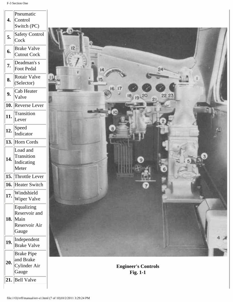
Engineer's Controls Fig. 1-1
4. Pneumatic Control Switch (PC)
5. Safety Control Cock
6. Brake Valve Cutout Cock
7. Deadman's s Foot Pedal
8. Rotair Valve (Selector)
9. Cab Heater Valve
10. Reverse Lever
11. Transition Lever
12. Speed Indicator
13. Horn Cords
14.
Load and Transition Indicating Meter
15. Throttle Lever
16. Heater Switch
17. Windshield Wiper Valve
18.
Equalizing Reservoir and Main Reservoir Air Gauge
19. Independent Brake Valve
20.
Brake Pipe and Brake Cylinder Air Gauge
21. Bell Valve
file:///O|/rrff/manual/err-s1.html (7 of 10)10/2/2011 3:29:24 PM

F-3 Section One
22.
Application Pipe and Suppression Pipe Air Gauge (if used)
23. Engineer's Watch Receptacle
24. Wheel Slip Indicator
25. Dynamic Brake Warning Light
Wheel Slip Indicator
For information, refer to "Locomotive Protective Devices," Section 2.
Speed Recorder
The speed recorder, located in front of the control stand, is an hydraulically operated speed indicator with recording tape and odometer. It is driven from an axle on the No. 1 truck of the "A" unit, through a flexible cable. Incorporated in the speed recorder is a micro-switch, which operates in conjunction with the "PC" switch if the train speed exceeds the maximum governed speed of the locomotive.
For further information on operation, see "Locomotive Overspeed" under "Locomotive Protective Devices," Section 2.
Dynamic Brake Warning Light
The dynamic brake warning light is mounted on the instrument panel and, when lit, indicates overload during dynamic braking. For further information, refer to "Operation of Dynamic Brake," Section 2.
Unit Selector Switch
The unit selector switch has four positions and should be set corresponding to the number of units making up the locomotive. The unit selector switch should be set before leaving the maintenance point and when isolating an engine enroute, this switch MUST NOT be changed. UNDER NO CIRCUMSTANCES should the switch be moved while using the dynamic brake. For further information, refer to Section 6.
Classification Lights
file:///O|/rrff/manual/err-s1.html (8 of 10)10/2/2011 3:29:24 PM

F-3 Section One
A permanently fixed, clear glass bull's-eye lens is provided on each side of the nose, immediately ahead of the locomotive number panel. Inside the nose and behind each bull's-eye, a small compartment contains the classification light bulb and colored lenses. A red and a green lens are provided in each compartment which can be moved into a position between the bulb and the bull's-eye. To accomplish this, a locking pin is removed, the desired lens swung into place and the locking pin replaced. The lenses are accessible from the inside of the nose section through hinged doors in the compartments. When both red and green lenses are out of position, the permanent bull's-eye lens will show a white light, thus making three colors available.
ENGINE CONTROLS
Distribution Panel
This panel is located in the electrical control cabinet and contains switches and fuses controlling the battery circuits throughout the unit. The battery ammeter, battery switch, fuse test light and test blocks are also mounted on this panel.
Engine Control and Instrument Panel
This panel is mounted on a frame which supports the engine cooling water tank at the governor end of the engine. Each power plant has its own engine control and instrument panel which incorporates the following controls and instruments.
Isolation Switch
The purpose of this switch is to open and close the control circuit of the engine as occasion demands. When starting the engine, this switch MUST be in the "START" position. After engine is running and it is desired to move the locomotive, the switch MUST be moved to "RUN" position. Low oil pressure protection is provided with the isolation switch in either "START" or "RUN" position.
This switch connects the control circuit of the engine to the engineer's controller. If it becomes necessary to isolate the engine, the isolation switch MUST be moved to the "START" position. This will bring the engine to idle and cut off the power of this engine. See subject under "ISOLATING AND STOPPING ENGINE WHILE UNDER POWER," Section 2.
The following equipment on the engine control and instrument panel is explained elsewhere in this manual, except in those cases in which no further explanation is necessary.
● Lube Oil Suction Gauge ● Main Bearing Oil Pressure Gauge ● Engine "START" Switch Button ● Engine "STOP" Switch Button ● Fuel Gauge ● Fuel Pump Switch ● Fuel Pump Contactor
file:///O|/rrff/manual/err-s1.html (9 of 10)10/2/2011 3:29:24 PM

F-3 Section One
● "ER" Relay
HAND BRAKE
The hand brake hand wheel is located in the engine room, to the right of the air compressors of both the "A" and "B" units. To set the brake, hold the foot pedal down and turn the wheel. To release the brake, advance the wheel enough to release the foot pedal latch and then let go of the wheel. Before moving the locomotive, be sure the brakes are completely released. Whenever anyone is working around the locomotive trucks, the hand brakes should be applied.
Ground Protective
Relay For information, refer to "Locomotive Protective Devices," Section 2.
Load Regulator
The load regulator is a control device which allows the engine to determine the load which it can pull, based or. fuel consumption. If the engine demands more fuel than a predetermined setting, the load regulator reduces the load on the engine by reducing the field excitation of the main generator. If the engine requires less fuel than the predetermined setting, or balance point, the load regulator increases the load on the engine by increasing field exci. tation of the main generator. In this manner, battery volt age, temperature changes in generator windings, or loco motive speeds, do not cause overloading or underloading of the engine.
The load regulator is divided into two sections; the pilot valve which is incorporated in the governor assembly, and a selfcontained unit in a structural steel frame, which consists of an hydraulic rotary vane-type motor attached to a commutator-type rheostat. The only external wiring connections are two leads to the generator field circuit for which a small terminal board is provided.
Layshaft Manual Control Lever
The layshaft manual control lever is attached to the end of the injector layshaft, and, if necessary, may be used to shut the engine down manually.
No A.C. Voltage Alarm
For information, refer to "Locomotive Protective Devices," Section 2.
file:///O|/rrff/manual/err-s1.html (10 of 10)10/2/2011 3:29:24 PM

F-3 Section Two
ELECTRO-MOTIVE DIVISION • GENERAL MOTORS CORPORATION SECTION F3-2-2 OPERATION
SECTION 2
LOCOMOTIVE OPERATION
Operating Instructions given in this section cover only locomotives equipped with manual transition. For operation of locomotives equipped with automatic transition refer to the blue insert at the end of this section.
Precautions Before Starting Engine
● 1. Check position of all valves: ❍ a. Drain valves in engine cooling system, lube oil system, and air reservoirs (valves should be closed). ❍ b. Steam admission valves in engine cooling system and steam line (valves should be closed).
● 2. Check fuel supply (gauge on engine control and instru ment panel). ● 3. Check engine cooling water supply (sight glasses on engine cooling water tank). ● 4. Check lubricating oil supply:
❍ a. In Diesel engine sumps (bayonet gauge on left side of engine oil pan). ❍ b. Engine governors (sight glass on governor). ❍ c. Air compressors (bayonet gauge in crankcase).
● 5. Close battery charging switches in electrical control cabinets.
Starting Engines After Layover
● 1. At Distribution Panel: ❍ a. Be sure all control fuses are in place:
■ 400-Ampere - Starting ■ 80-Ampere - Control ■ 30-Ampere - Control ■ 15-Ampere - Fuel Pump ■ 10-Ampere - Fuel Pump Motor
❍ b. Close main battery switch. ❍ c. Close master control switch. ❍ d. Close light or train control-speed governor switch as required.
● 2. At Engineer's Control Station: ❍ a. Place throttle in "IDLE" position. ❍ b. Close control push-button switch. ❍ c. Close fuel pump switch. ❍ d. Set "PC" switch.
● 3. At Engine: ❍ a. Test for water accumulation in cylinders. Open cylinder test valve at each cylinder. Place isolation
switch in "START" position and fuel pump switch in "OFF." Hold governor power piston in "shut-down" position, by use of layshaft manual control lever, and turn engine several revolutions by pressing the
file:///O|/rrff/manual/err-s2.html (1 of 18)10/2/2011 3:29:47 PM

F-3 Section Two
engine "START" button. If discharge of water or fuel appears at the test valves, do not start engine until cause of the discharge is located and corrected.
❍ b. Close cylinder test valves. ❍ c. Check 10-ampere fuel pump motor fuse on distribution panel. ❍ d. Check position of lube oil shut down trip on governor. ❍ e. See that isolation switch is in "START" position. ❍ f. Close fuel pump switch on engine control and instrument panel and watch for fuel in sight glass nearest
engine on sintered bronze filter assembly on front of engine. This will indicate that fuel is circulating through engine fuel oil system.
❍ g. Press engine "START" button and hold in until engine starts. If engine fails to start after being rotated 10 to 15 seconds, release "START" button and ascertain cause of difficulty.
❍ h. After lubricating oil pressure builds up, place isola tion switch in "RUN" position. ❍ i. Allow engine to idle until water temperature come: up to 125° F., before moving locomotive.
● 4. At electrical control cabinet: ❍ a. Check starting contactors and make certain both are open. ❍ b. Check ground protective relay and make certain it is not tripped.
Pumping Up Main Reservoir Air Pressure
If the locomotive has been standing inoperative and the air reservoirs have been drained:
● a. Close all drain cocks in air system. ● b. Place reverse lever in the "neutral" position. ● c. Place independent brake valve in "application" posi tion (this will prevent "PC" switch from tripping). ● d. Start engines in the usual way but do not close the generator field switch. ● e. Let engines idle for at least five minutes.
To Move Locomotive:
● a. Release all hand brakes. ● b. Isolation switches on engine control and instrument, panel must be in "RUN" position. ● c. Close generator field switch on engineer's control push button switch box. ● d. Place reverse lever in "forward" or "reverse" position as required. ● e. Place transition lever in No. 1 position. ● f. Place foot on deadman foot pedal and release air brakes. ● g. Open throttle as required.
● a. Place reverse lever in "neutral" position. ● b. Pull out generator field switch. ● c. Place transition lever in No. 1 position. ● d. Open throttle, if necessary, to 3rd position. ● e. After air has been pumped up, close throttle and push generator field switch in.
Starting a Train
Due to the unusual amount of starting tractive effort of this locomotive, it is highly essential that no attempt be made to start the train before the air brakes are completely released. Tests on a 100-car train have indicated that this time may be as much as 9 minutes after the brakes have started to release. It is recognized, however, that a normal 100-car train
file:///O|/rrff/manual/err-s2.html (2 of 18)10/2/2011 3:29:47 PM

F-3 Section Two
should not require more than five (5) minutes for the complete release of the brakes.
It is never necessary to move the throttle or any other controls hastily. Each move should be thought out carefully and made smoothly.
With the high tractive effort at starting of this locomotive, it is seldom necessary to bunch slack. If a tight train will not start, look for air brake trouble. Bunching slack and starting with a jerk might result in damaged couplers.
Caution should be observed in ordinary handling of the throttle so that the throttle "STOP" button is not pressed in error when closing the throttle. If this is done, the engines will stop and cause a delay while restarting.
When two "A" units are used to make up a locomotive, caution MUST be taken not to leave the reverse lever in the controller of the trailing "A" unit. If the lever is left in the controller, it might accidentally be moved, causing a flashover, sliding the wheels, or both.
Proceed in general as follows:
● a. Place transition lever in No. 1 position. ● b. Open throttle to whatever position is necessary to start the locomotive and begin to move the train, holding the
throttle in each position for approximately 2 seconds (not more than 3 seconds) before moving it to the next position. See NOTE below.
● c. After the locomotive starts, reduce the throttle (if necessary) to a position which will just keep the locomotive moving until all the slack is out. The throttle may then be advanced to any desired position.
When starting a train with the slack bunched or partially bunched, it should seldom be necessary to open the throttle beyond the No. 4 position on a four-unit locomotive, and No. 5 on a two-unit or threeunit locomotive. If the locomotive fails to start, or stops while stretching slack in these throttle positions, sticking brakes may be the cause of difficulty.
If the slack is stretched or a start is being made on a grade, it may be necessary to advance the throttle to positions beyond those given above for the different locomotive unit combinations. Judgment must be exercised in handling the throttle in such cases, particularly with four-unit locomotives, to avoid pulling of drawbars. See NOTE below. NOTE: If slipping occurs as indicated by the wheel slip indicator flashing on and off, ease off on the throttle until slipping stops and then apply sand. DO NOT APPLY SAND UNTIL AFTER THE WHEEL SLIPPAGE HAS STOPPED. The throttle may again be advanced to the positions at which slipping took place and the throttle movement continued if no slippage occurs.
Operating Reverse Lever
UNDER NO CONDITION should the reverse lever be moved while the locomotive is in motion. When leaving the locomotive; the reverse lever should be removed from the controller. If two "A" units are used in making up the consist of the locomotive, the reverse lever should always be removed from the controller of the trailing "A" unit.
There is no mechanical connection between the reverse lever on the controller and the reverser drums in the electrical control cabinets. The reverser drums are operated by electro-pneumatic control from the operating cab.
When the transition lever is in "OFF" position, the reverser drums will move to "forward" or "reverse" position when the reverse lever is operated in the cab. When the transition lever is in No. 1 position, the reverser drums will not change when the reverse lever is moved, unless the throttle is opened to Run 1.
file:///O|/rrff/manual/err-s2.html (3 of 18)10/2/2011 3:29:47 PM
F-3 Section Two
Use of Load and Transition Indicating Meter
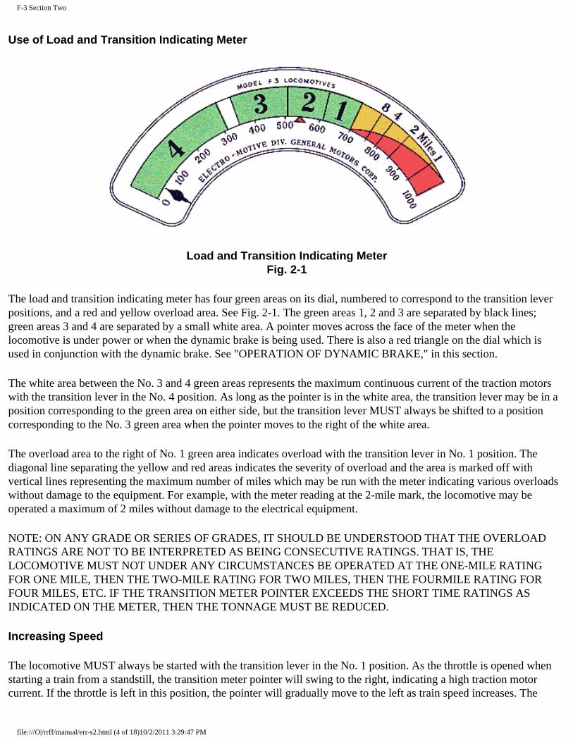
Load and Transition Indicating Meter Fig. 2-1
The load and transition indicating meter has four green areas on its dial, numbered to correspond to the transition lever positions, and a red and yellow overload area. See Fig. 2-1. The green areas 1, 2 and 3 are separated by black lines; green areas 3 and 4 are separated by a small white area. A pointer moves across the face of the meter when the locomotive is under power or when the dynamic brake is being used. There is also a red triangle on the dial which is used in conjunction with the dynamic brake. See "OPERATION OF DYNAMIC BRAKE," in this section.
The white area between the No. 3 and 4 green areas represents the maximum continuous current of the traction motors with the transition lever in the No. 4 position. As long as the pointer is in the white area, the transition lever may be in a position corresponding to the green area on either side, but the transition lever MUST always be shifted to a position corresponding to the No. 3 green area when the pointer moves to the right of the white area.
The overload area to the right of No. 1 green area indicates overload with the transition lever in No. 1 position. The diagonal line separating the yellow and red areas indicates the severity of overload and the area is marked off with vertical lines representing the maximum number of miles which may be run with the meter indicating various overloads without damage to the equipment. For example, with the meter reading at the 2-mile mark, the locomotive may be operated a maximum of 2 miles without damage to the electrical equipment.
NOTE: ON ANY GRADE OR SERIES OF GRADES, IT SHOULD BE UNDERSTOOD THAT THE OVERLOAD RATINGS ARE NOT TO BE INTERPRETED AS BEING CONSECUTIVE RATINGS. THAT IS, THE LOCOMOTIVE MUST NOT UNDER ANY CIRCUMSTANCES BE OPERATED AT THE ONE-MILE RATING FOR ONE MILE, THEN THE TWO-MILE RATING FOR TWO MILES, THEN THE FOURMILE RATING FOR FOUR MILES, ETC. IF THE TRANSITION METER POINTER EXCEEDS THE SHORT TIME RATINGS AS INDICATED ON THE METER, THEN THE TONNAGE MUST BE REDUCED.
Increasing Speed
The locomotive MUST always be started with the transition lever in the No. 1 position. As the throttle is opened when starting a train from a standstill, the transition meter pointer will swing to the right, indicating a high traction motor current. If the throttle is left in this position, the pointer will gradually move to the left as train speed increases. The
file:///O|/rrff/manual/err-s2.html (4 of 18)10/2/2011 3:29:47 PM

F-3 Section Two
pointer will react in the same manner with each succeeding advance in throttle position. With the throttle in Run 8 position, as the pointer moves to the left and crosses the black line between the No. 1 and No. 2 green areas, the transition lever should be moved to the No. 2 position. This procedure should be followed when the pointer crosses each succeeding black line or white area. Transition should be made from No. 3 to No. 4 when the pointer has passed completely through the white area. The pointer should always be in the numbered area corresponding to the position of the transition lever with the throttle in the Run 8 position, and in this area, or to the left of it, in any. lower position of the throttle.
Decreasing Speed
As the train speed decreases due to a grade, the pointer will gradually move to the right. When the pointer crosses the white area from 4 to 3, or the black lines between the other areas the transition lever MUST be moved to the position indicated. This MUST be done regardless of the throttle position.
No damage will result in failing to advance the transition lever with increasing speed. But the electrical equipment will be overloaded and serious damage might result if the lever is not backed off at the point indicated when the locomotive speed is decreasing due to a grade. The transition lever should be in the No. 1 position before the locomotive comes to a stop.
Operation of Transition Lever
The transition lever, located on the top of the controller, has four positions to give four connections of the traction motors.
A definition of transition is inserted at this time so that the term will not be confusing. Transition is the changing of the traction motor connections to obtain the desired locomotive tractive effort and speed.
These positions are:
No. 1
SERIES-PARALLEL No. 1 and No. 4 traction motors are connected in series. No. 2 and No. 3 motors are also connected in series. In the No. 1 position of the transition lever, these two groups are then connected in parallel.
No. 2
SERIES-PARALLEL-SHUNT The same as Series-Parallel but with the fields of each motor shunted by resistors.
No. 3
PARALLEL All four motors are connected in parallel.
No. 4
PARALLEL-SHUNT The same as Parallel but with the fields of each motor shunted by resistors.
The transition lever slides in a slot which is notched both top and bottom. The lever has lugs on the top and bottom which engage in these notches, so that the lever can only be moved from one notch to the next by proper manipulation. The lug on the top is integral with the lever, while the lug on the bottom can be depressed up into the lever. See Fig. 2-3. To move the lever from one position to the next, the lever is lifted (A) and while it is held up against the top of the slot (B) it is moved in the direction desired with the lever held against the top and side of the upper slot (C). The lever is then lowered (D) which compresses the bottom lug (E) allowing the lever to be moved to the next position (F).
file:///O|/rrff/manual/err-s2.html (5 of 18)10/2/2011 3:29:47 PM

F-3 Section Two
Transition Lever and Sectors Fig. 2-2
Transition Lever Operating Diagram Fig. 2-3
CONTINUOUS TONNAGE RATING FIGURES
FOR F3 LOCOMOTIVE
GEAR RATIO
file:///O|/rrff/manual/err-s2.html (6 of 18)10/2/2011 3:29:47 PM

F-3 Section Two
HP GRADE 65/12 62/15 61/16 60/17 59/18 58/19 57/20 56/21
6000 1.0% 6450 4780 4370 3960 3700 3370 3110 2880 6000 1.5% 4470 3280 3000 2700 2520 2280 2100 1920 6000 2.0% 3360 2460 2230 2000 1870 1680 1540 1440 4500 1.0% 4840 3580 3280 2970 2770 2530 2330 2160 4500 1.5% 3350 2460 2250 2020 1890 1710 1570 1440 4500 2.0% 2520 1840 1670 1500 1400 1260 1150 1080 3000 1.0% 3220 2390 2180 1980 1850 1680 1550 1440 3000 1.5% 2230 1640 1500 1350 1260 1140 1050 960 3000 2.0% 1680 1230 1110 1000 930 840 770 720 1500 1.0 % 1610 1190 1090 990 920 840 780 720 1500 1.5% 1120 820 750 670 630 570 520 480 1500 2.0% 840 610 560 500 470 420 380 360
APPROXIMATE SPEEDS AT ABOVE RATINGS:
12.0 15.5 17.0 18.5 19.5 21.0 22.5 24.5
These speeds MUST NOT be used for rating the tonnage, but only to give a close approximation of the running speed with rated tonnage.
With the above tonnage ratings, all engines must be up to full rated output. If an engine is low in power, or an engine is "off the line," the tonnage should be adjusted in proportion to the decreased power.
In order to avoid overloading the electrical equipment, it is important that the tonnage of the train be kept within the maximum tonnage rating limits of the locomotive except where SPECIAL TONNAGE RATINGS have been supplied to the railroad by the Engineering Department of ElectroMotive Division.
Steam Locomotive Used As Helper
In moving large tonnage trains over heavy grades ordinarily encountered in mountainous territories, steam locomotives are generally used for helper service. In such a movement, it must be known that the steam locomotive can and will pull, as its share of the load, the tonnage of the train which is in excess of the maximum continuous tonnage rating of the Diesel locomotive for the grade over which the train is moved. The steam locomotive must be capable of pulling its share of the tonnage without danger of slipping.
Steam locomotives used as helpers often have tonnage ratings based on speeds lower than the continuous rated speed of the Diesel locomotive. Above such speeds, the Diesel locomotive will absorb more than its proportionate share of the load since its tonnage rating is based on the higher speed. As a result, the Diesel locomotive may become overloaded in endeavoring to maintain minimum speed for its continuous rating. This will be indicated by the transition indicating meter pointer moving to the right of the No. 1 green area into the overload area.
Under these conditions, reduce the Diesel locomotive throttle, allowing the train speed to drop and the steam locomotive
file:///O|/rrff/manual/err-s2.html (7 of 18)10/2/2011 3:29:47 PM

F-3 Section Two
to pick up its proper share of the tonnage. When the pointer reaches the No. 1 green area, the steam locomotive will have assumed enough tonnage to remove the overload from the Diesel locomotive. Operation should be continued at this throttle position.
Should the transition meter be out of order it will be necessary to handle the throttle by reference to the speed indicator instead of the transition indicating meter. In this case, the table of "Approximate Continuous Speed Ratings" on page 212 should be used. To apply the data in the table, reduce the throttle notch by notch. After each throttle reduction, allow the train speed to become steady and read the speed indicator. Compare the reading with the figure in the table opposite the throttle position being used and in the column corresponding to the gear ratio of the locomotive. If the train speed is lower than the table figure, reduce the throttle another notch and repeat the procedure, comparing the speed with the line in the tale for the new throttle position. Continue the throttle reduction until the train speed becomes equal to or higher than the table speed reading. Continue operation at this throttle position.
APPROXIMATE CONTINUOUS SPEED RATINGS
Miles per hour with 40" wheels
Throttle 65/12 62/15 61/16 60/17 59/18 58/19 57/20 56/21 8 12 15.5 17 18.5 19.5 21 22.5 24.5 7 9.5 12 13 14 15 16 17.5 18 6 7.5 9.5 11 11.5 12 13 14 14.5 5 6 7 7.5 8 9 10 10.5 11
An example of the use of the table is given below:
Assume the locomotive is one with 62/ 15 gear ratio. When operating in transition No. 1 and throttle Run 8, with a helper locomotive, the train speed drops to 11.0 MPH. This is under the 15.5 MPH shown in the table for a 62/15 gear ratio locomotive in throttle Run 8. The locomotive is overloaded and if the transition indicating meter were working, the pointer would be to the right of the No. 1 green area (700 amperes). The throttle is then reduced to Run 7. The speed drops to 10 MPH and the helper locomotive assumes more load. The locomotive is still overloaded since the table shows 12.0 MPH. The throttle is next moved to Run 6. The speed becomes steady at 9.5 MPH. This checks with the Continuous Speed Rating in the table and operation should lie continued with the throttle in this position.
Operating Without Load and Transition Indicating Meter
If at any time the transition meter does not function properly, or the lead unit has been isolated, it will be necessary to make transition by reference to the locomotive speed. The table below shows the approximate speeds at which transition should occur.
MILES PER HOUR WITH 40" WHEELS
Move Transition Lever
file:///O|/rrff/manual/err-s2.html (8 of 18)10/2/2011 3:29:47 PM

F-3 Section Two
From To GEAR RATIO Pos. Pos. 65/12 62/15 61/16 60/17 59/18 58/19 57/20 56/21 1 2 15.0 19.5 21.0 23.0 24.5 26.5 28.0 30.0 2 3 19.5 25.5 27.5 30.0 32.0 35.0 37.0 40.0 3 4 41.0 53.0 58.5 63.0 67.0 72.0 78.0 83.0 4 3 41.0 53.0 58.5 63.0 67.0 72.0 78.0 83.0 3 2 19.5 25.5 27.5 30.0 32.0 35.0 37.0 40.0 2 1 15.0 19.5 21.0 23.0 24.5 26.5 28.0 30.0
Maximum Permissible Speed 50 65 71 77 83 89 95 102
Transition should be made in accordance with reading of transition meter and should never be made from speed indicator reading, except when the transition meter fails to function.
Handling of Locomotive
Under NO condition should the reverse lever be movad while the locomotive is in motion. When the Diesel locomotive is pulling a train either with or without helper service, the handling of the throttle and shifting of the transition lever MUST be in accordance with instructions in this manual. When leaving the locomotive, the reverse lever should be removed from the controller.
If two "A" units are used in making up the locomotive, the reverse lever should always be removed from the controller of the trailing cab.
Operating Over Railroad Crossings
The throttle MUST always be reduced until all power trucks have passed over the crossing. This is to prevent arcing of the brushes on the commutators of the traction motors. If running with the throttle above the 5th position, reduce throttle to 5th position. If running in 4th or 5th position, reduce throttle one position.
Air Braking With Power
In order to keep the train stretched on a rolling grade, it might be necessary to brake the train with power still supplied by the locomotive. In this case, the throttle should be reduced to at least the 6th position. It is very important that the locomotive air brakes be released and kept in the released position when the locomotive is supplying power. This MUST be observed.
When preparing to stop with power applied to locomotive and brakes applied to the train, it is necessary to reduce the throttle as the train speed decreases. As the train slows down, the pulling power of the locomotive increases rapidly and might become great enough to part the train if the throttle were not reduced. The throttle should be in "IDLE" at least 100 feet before the locomotive comes to a full stop.
Running Through Water
file:///O|/rrff/manual/err-s2.html (9 of 18)10/2/2011 3:29:47 PM

F-3 Section Two
Under ABSOLUTELY no circumstances should the locomotive pass through water which is deep enough to touch the bottom of the traction motor frames. When passing through water, always go at a very slow speed (2 to 3 miles per hour). Water any deeper than 3 inches above the top of the rails is likely to cause damage to the traction motors.
Precautions During Locomotive Operation
● 1. Check engine cooling water temperature. Temperature should be maintained at 165° F., plus or minus 15° F. If temperature is not in this range, report this fact at the first maintenance point. Do not attempt to adjust the shutters. For instructions in case of hot engine alarm due to excessive water temperature, refer to "Trouble Shooting," Section 9.
● 2. Lubricating oil pressure should be 35 to 45 pounds (hot oil) at 800 RPM. If main bearing pressure drops below 20 pounds at 800 RPM (hot oil), stop the engine and investigate.
● 3. The fuel sight glasses on the sintered bronze filter assembly should be observed frequently to check supply of fuel to the engine.
● 4. Observe the auxiliary generator ammeters in the electrical control cabinet periodically to see that they are indicating a charge.
● 5. Check traction motor blowers. If a blower is not oper ating properly, isolate engine until condition is corrected. ● 6. Electric control air pressure should be 80 pounds plus or minus 3 pounds.
Isolating and Stopping Engine While Under Power
If it becomes necessary to take the engine "off the line" while the locomotive is operating under power, it should be done as follows:
● 1. Reduce the speed of the engine to idle with the layshaft manual control lever so that the traction motor contactors will not have to interrupt the full traction motor current.
● 2. Place the isolation switch in the "START" position. ● 3. Press the engine "STOP" button in until engine stops. ● 4. Place fuel pump switch in "OFF" position.
If the power plant of the leading unit is isolated while the locomotive is under power, the transition meter will not function; therefore, transition must be determined by the speed indicator according to the figures given under the paragraph "Operating Without Load and Transition Indicating Meter."
Starting and Placing Engine on the Line While Locomotive Is Under Power
● 1. Start engine in the usual way. (See paragraph 4, "Starting Engines After Layover," this section.) ● 2. After lubricating oil pressure builds up, place isolation switch in "RUN" position. If throttle is above 3rd
position, hold off on governor to injector linkage with layshaft manual control lever, to allow engine to come up to speed gradually.
Starting and Placing Engine on the Line After "LOW OIL" Alarm
Refer to "Engine Stopped" in Section 9.
DYNAMIC BRAKE
file:///O|/rrff/manual/err-s2.html (10 of 18)10/2/2011 3:29:47 PM

F-3 Section Two
The dynamic brake is an electrical retarding device which utilizes the main generator and traction motors to retard the speed of the train. The dynamic brake is in no way connected to the air brake system and is only effective when the Diesel engines are running and the train is in motion. With the wheels turning, the traction motors act as generators and the power generated is dissipated through heavy resistors, called grids, located in the dynamic brake blower hatch assembly.
Operation of Dynamic Brake
Located next to the instrument panel at the engineer's control station is the unit selector switch. The selector switch should be set before leaving the maintenance point to agree with the number of units making up the consist of the locomotive. When isolating an engine enroute, this switch MUST NOT be changed. Under NO circumstances should the switch be moved while using the dynamic brake.
If a "B" unit is to be used as the trailing unit, the field loop jumper must be removed from its receptacle at the rear end of the unit. When the receptacle is empty, a shortcircuiting bar closes the loop circuit. The clamps on all loop circuit receptacles must be kept tight.
To apply the dynamic brake, move the throttle to "IDLE" position and lift the transition lever over the stop to the "OFF" position. After a few seconds, move to the "B" position. The dynamic brake effort is sufficient in this position to bunch the train slack gradually. But the greater the train speed, the stronger the brake effect in the initial position, so the same care should be used in applying the dynamic brake as is used when using the independent air brake. DO NOT use the dynamic brake and the independent air brake simultaneously, as there is the possibility of sliding wheels. When it is certain that the slack is bunched, the lever can be moved to the right to give the desired braking.
The load and transition indicating meter indicates the traction motor current when using the dynamic brake as well as when motoring. The red triangle indicates the maximum allowable traction motor current when using the dynamic brake, and the pointer should not be allowed to move to the right of this red triangle. If the transition meter is disregarded while braking, a dynamic brake warning light mounted on the instrument panel in the cab will flash at the danger point. If the lever is backed off, the light will go out but will come back on if the train speed increases. If it is impossible to maintain the desired train speed with the dynamic brake, the automatic air brakes should be applied in conjunction with the dynamic brake. Keep locomotive independent air brakes released to avoid wheel slide.
When releasing the dynamic brake, care must be used not to release it so suddenly as to cause "run-out" which may pull a drawbar. If necessary, a light independent air application may be made after the dynamic brake is released.
It is permissible, but not practical, to come to a full stop with the dynamic brake. As the locomotive speed decreases, the braking effect of the dynamic brake decreases, so that it will take a long time for the train to stop. At speeds below 8 MPH when bringing the train to a stop, it is suggested that as the transition lever is moved toward the "OFF" position, a light application be made on the independent air brake, so as to prevent "run-out" of the locomotive.
It is also permissible to start from a standstill with the dynamic brake applied, provided the grade will permit the train to start without applying power.
Differences in idling speed of the engines and variation in the motor and generator characteristics may cause the dynamic brake warning light to come on before the transition meter pointer reaches the red triangle, but in any case, the light must not be on. The light is an indication of an overload, and operating with it "on" might damage the traction motors and braking grids.
file:///O|/rrff/manual/err-s2.html (11 of 18)10/2/2011 3:29:47 PM

F-3 Section Two
Isolating an Engine While using Dynamic Brake
The dynamic brake can be made inoperative on any unit by placing the isolation switch of that unit in the "START" position. However, except in the case of an emergency, the isolation switch should not be moved to "START" position while the transition lever is advanced to the right, beyond the "B" position. Isolating an engine when using the dynamic brake causes the motor load to be removed suddenly, which will cause a high inductive voltage to be built up and this might be great enough to break down the main contactor insulation.
If in an emergency it should become necessary to isolate an engine when using the dynamic brake, it should be done by first stopping the engine, using the layshaft manual control lever, then moving the isolation switch to the "START" position.
Isolating an engine may become necessary due to failure of the dynamic brake equipment on that unit, or failure of the Diesel engine. This opens the braking contactors but leaves the main generator battery field connected in series with the other generator fields throughout the locomotive. DO NOT change the position of the unit selector switch.
The isolation switch should not be moved to "RUN" position while the dynamic brake is in operation. If this precaution is not observed, the dynamic brake on this unit will be applied suddenly and will result in an overload to the electrical equipment and the possibility of sliding the wheels. The transition lever must be moved to "OFF" position before opening or closing an isolation switch.
When the power plant of the leading unit is isolated, the load and transition indicating meter in this unit will not function. This is because the traction motors on this unit are not generating. Therefore, particular attention must be given to the dynamic brake warning light, as this will be the only guide to dynamic brake overload.
Normal Operating Instructions - #24 Brake Valve (24-RL Brake Equipment)
A Rotair valve is installed alongside the independent brake valve. There are four positions of this valve indicated in raised letters: Passenger, Passenger-Lap, Freight, and Freight-Lap. If a long freight train is being hauled, this valve should be set in the "Freight" position. This will insure a controlled emergency application. In short freight trains and passenger trains where the controlled emergency feature is not desired, the Rotair valve should be placed in "Passenger" position.
The brake valve cutout cock is the leading "A" unit should be in the "Live" position (handle pointing forward). This valve is situated in the Filling Piece Portion of the #24 brake valve.
The safety control cock situated in the Application Portion of the # 24 brake valve should be in the "ON" position, as this will insure operation of all safety devices, deadman foot valve, locomotive overspeed, and train control. This valve may be sealed, if desired.
The equipment includes a controlled release feature. The full release selector cock is located on the left-hand side of the brake valve rotary valve seat. When the cock handle is moved away from the engineer toward the letters MR cast on the cock body, air at main reservoir pressure is supplied to the chamber above the automatic rotary valve as in the No. 6 ET and No. 8 ET equipment. This provides maximum rate of brake pipe recharge when the brake valve is in release position but overcharging is possible. When the selector cock is moved to the FV position (handle pointing toward engineer), air at pressure controlled by a large capacity feed valve is supplied to the same chamber. With the selector cock handle in this position and the automatic brake valve handle in release position, brake pipe recharge is obtained at a rate which represents the maximum that is possible.
file:///O|/rrff/manual/err-s2.html (12 of 18)10/2/2011 3:29:47 PM

F-3 Section Two
A cock located on the right-hand side of the # 24 brake valve, in the Filling Piece Portion, cuts in or out the first service position of the automatic brake handle. Furthermore, if the cock is "in" (handle pointing towards engineer) the time rate of a safety control application is lengthened. If the cock is out (handle pointing towards cab window) the time rate of a train control application is shortened.
At Control Valve in Nose
There are two cocks and one cap in this control valve. The charging change over cock has a freight and passenger position. When in "Freight" position, charging of pressure chamber is slow; when it is in "Passenger" position, charging of pressure chamber is fast. The Dead Engine cock will be closed (Live position) in normal operation and open (DEAD position) in case locomotive is being hauled dead in the train. The cap, situated in the rear of the control valve, has two settings, "Graduated" and "Direct." This applies to independent release which will usually be graduated in passenger trains and direct in freight trains.
Locomotive Overspeed Cutout
The overspeed control feature can be cut out by closing magnet valve air supply line 3/8" cutout cock on air brake equipment rack.
Deadman Foot Pedal
Should both of the brake valve handles and the deadman foot pedal be placed in the released position when the brakes are released, a service application will result through operation of the safety control feature. On locomotives having the time delay feature, a warning whistle on the brake valve will sound. If the automatic brake valve handle or the foot pedal is depressed within 4 to 6 seconds, the application will be suppressed. To release a safety control application, depress either the brake valve handle or the foot valve pedal and move the automatic brake valve handle to "LAP" position until the application portion releases and the application pipe gauge shows substantially main reservoir pressure. Then move automatic brake valve handle to "RELEASE" position in the normal manner.
Deadman Cutout
The deadman safety control feature can be cut out by closing 3/8" cutout cock in line from relay air valve unit located on air brake equipment rack.
TOWING LOCOMOTIVE
● 1. Be sure reverse lever is in neutral position. If the loco motive is to be towed in a train any appreciable distance, the reverser drum must be placed in neutral position manually and should be locked in that position. During normal operation, a locking pin is screwed into the lefthand side of the reverser. To lock the reverser drum in neutral, this pin should be removed and inserted in the hole on the opposite side. Turn the drum to its neutral position and the pin will engage with the hole in the shaft.
● 2. The transition lever must be moved to the "OFF" position before the control push-button is pulled out. This moves the cam-switch to the "TOW" position. If this is not done, the traction motors will generate, causing the wheels to slide if the locomotive is towed in a direction opposite to the position of the reverser.
● 3. All isolation switches must be in "START" position. If it is necessary to keep engines idling far any reason while towing locomotive, the fuel pump and control switches should be left in the closed position.
● 4. For setting of air brake equipment, see the air brake manufacturer's instruction bulletin.
file:///O|/rrff/manual/err-s2.html (13 of 18)10/2/2011 3:29:47 PM

F-3 Section Two
CHANGING OPERATING ENDS
When the consist of the locomotive includes two "A" units, the following procedure should be followed in changing from one operating end to the opposite end:
● a. Remove reverse lever. ● b. With deadman control pedal depressed, release independent air brake by placing independent brake valve
handle in "RELEASE" position. ● c. Make full service automatic brake application. ● d. Close brake valve cutout cock and release deadman control pedal. ● e. Move the Rotair valve to the proper "LAP" position. ● f. Move the automatic brake valve handle to "RUNNING" position and remove the handle from the brake valve. ● g. Remove the independent brake valve handle in "RELEASE" position. ● h. Open all switches in control push-button box and close the switch lock. ● i. Proceed to cab at opposite end. Check "PC" switch and reset if necessary. Open switch ,lock on control
pushbutton switch box, close control and fuel pump switches and such other switches as are necessary. ● j. Insert reverse lever, automatic brake valve handle and independent air brake handle. ● k. Move the Rotair valve to the proper operating position. ● l. Move independent brake valve handle to "FULL APPLICATION" position and open the brake valve cutout
cock slowly, pausing from 5 to 10 seconds in mid-position. ● m. When ready to move locomotive, depress deadman control pedal or automatic brake valve handle and move
independent brake valve handle to "RELEASE" position.
Stopping Engine in Preparation For Terminal Layover
● 1. At Engineer's Control Station: ❍ a. Close throttle to "IDLE" position. ❍ b. Place transition lever in "OFF" position. ❍ c. Place reverse lever in "neutral" position and remove lever from controller. ❍ d. Open generator field switch. (Do not open control switch, as it is impossible to shut down engines with
"STOP" button unless the control push-button switch is closed.) ● 2. At Engine:
❍ a. Place isolation switch in "START" position. ❍ b. Push engine "STOP" button in and hold it until engine stops. ❍ c. Place fuel pump switch in "OFF" position. ❍ d. Open cylinder test valves on engine.
LOCOMOTIVE PROTECTIVE DEVICES
Pneumatic Control Switch
The pneumatic control switch is an air-operated electric switch located on the right-hand side of the cab below the window. The purpose of the switch is to reduce the power of the locomotive by bringing the speed of the engines to idle when either of the following air brake applications take place: deadman, train control, locomotive overspeed, or any emergency brake application. The automatic brake valve must be placed in "LAP" position until application pipe air pressure builds up to normal. The switch has a manual reset button which must be pulled out after the brakes have been released. This switch is referred to as the "PC" switch.
file:///O|/rrff/manual/err-s2.html (14 of 18)10/2/2011 3:29:47 PM

F-3 Section Two
When the "PC" switch operates, it opens the fuel pump control circuit on all units, thereby stopping the fuel pumps and deenergizing the "ER" relay in all units, thus reducing the engine speed to idle and after a short period of time the engines will starve for fuel and stop. De-energizing the fuel pump contactors opens the control circuit for the radiator cooling fan motors and the cooling system shutters, causing the fans to stop and the shutters to close.
Engines will stop if "PC" switch opens when the throttle is in 5th or 6th position.
Emergency Operation of "PC" Switch
When the brake pipe is vented at the emergency rate, the piston' in the emergency portion of the control valve moves to the emergency position, thus connecting a pipe to the auxiliary reservoir. This pipe is connected to a double check valve which in turn is connected to the "PC" switch.
Main reservoir pressure operates the "PC" switch when any application is made from the "M" application valve.
When the "PC" switch is operated from the emergency portion of the control valve, auxiliary reservoir pressure is used. (Auxiliary reservoir is normally charged to feed valve pressure.)
The "PC" switch is set to operate, or trip, at 40 pounds air pressure and reset at 20 pounds.
Operation of Wheel Slip Indicator
Whenever one pair of wheels slips on one or more trucks of the locomotive, the wheel slip indicator on the engineer's instrument panel will light. To stop the slippage, ease off on the throttle one or more positions. After the wheels stop slipping, indicated by the light going out and staying out, the throttle may be opened to the desired position.
The light will not burn continuously when wheels slip, because the wheels will not slip continuously. The connections of the wheel slip relay to the power plant are such that the power is automatically reduced when the wheels slip. Therefore, the wheels will slip, then stop, slip again and stop - about once a second.
When there is a wheel slip indication, it will probably be only one set of wheels that are slipping, unless the rail conditions are extremely bad. On these locomotives with many traction motors, all of which exert their tractive effort independently, with the connections as outlined above, a wheel slip indication usually means only a partial and temporary loss of tractive effort.
It is, therefore, unnecessary to use sand except under the worst track conditions. Before applying sand, be sure to reduce the throttle until the wheel slip light stops flashing. It should be remembered that sand is injurious to the traction motors and associated equipment.
If one pair of wheels is locked, due to a broken pinion or axle gear, or the armature shaft frozen in its bearings, the wheel slip signal will light and will stay on as long as current is being supplied to the motors. This is true except in the case of very low locomotive speeds due to the fact that a definite difference in potential between the traction motors is required to make the wheel slip relay function with the motor circuit in the series-parallel or parallel position. Therefore, the locomotive speed must be great enough to bring about this difference in potential for any wheel slip indication to be given.
During transition from series-parallel-shunt to parallel, the wheel slip relay will pick up, causing the wheel slip light to flash. This is not an indication that the wheels are slipping.
file:///O|/rrff/manual/err-s2.html (15 of 18)10/2/2011 3:29:47 PM

F-3 Section Two
The wheel slip relay will give wheel slip indication for both series-parallel and parallel operation.
Governor Safety Control
In case of low oil pressure or high vacuum on the suction side of the lube oil and piston cooling oil pumps, the engine governor will stop the engine. The alarm bells will sound in all units of the locomotive. The yellow "LOW OIL" and the blue "Alternator Failure" signal light will show in the unit concerned.
When the governor safety control stops the engine, a push-button on the front of the governor housing moves out approximately 3/8" exposing a red band around the shaft of the button. The governor reset push-button must be pressed in to put out the "LOW OIL" alarm lights and the isolation switch moved to "START" position to cut out the "Alternator Failure" alarm lights. Both actions are necessary to stop the alarm bells.
The push-button will not trip if the engine stops due to placing of throttle in emergency stop position, operation of manual layshaft control lever, tripping of ground protective relay when throttle is in Run 5 or Run 6 or use of the "STOP" button for normal shut down. In these instances the "LOW OIL" alarm lights will not light but the "ALTERNATOR FAILURE" alarm will function (except when the "STOP" button is used) to serve as a warning that an engine is stopped.
When the engine is stopped by governor control action, the pushbutton must be reset before the engine can be started. When the engine is started and run at idling speed, the governor will stop the engine again after approximately 40 seconds, if the condition still exists which caused the original shutdown. This time delay is provided to allow a check to determine the cause of the shutdown. However, if an attempt is made to run the engine above idling speed during the delay period, the governor will stop the engine at once should the oil pressure be low or the oil pump suction be high.
Engine Overspeed Trip
This is a flyweight on the engine camshaft which operates small cams under each injector rocker arm to raise the rocker arm cam followers off the camshaft cam, thus preventing injection of fuel. The trip operates at approximately 880 RPM of the engine. The overspeed trip may be caused to operate by a sudden loss of electrical load, such as wheel slippage or ground relay tripping.
The overspeed trip resetting lever is located on the front end of the engine directly behind the engine governor. If trip operates, it can be reset by turning lever in a counterclockwise direction until it latches.
Engine High Temperature Alarm Switch
This is a thermal switch located on the left side of the locomotive, between the grid hatch and the cooling hatch next to the shutter magnet valve. It connects with one thermal element in the water outlet manifold of the engine. If the water temperature exceeds 208° F., this switch closes, lights the hot engine alarm signal light only in the unit having high cooling water temperature, and energizes the signal relay, which rings the alarm bell. The tube leading from the element to the switch must not be kinked or dented.
No A.C. Voltage Alarm
A "No A.C. Voltage" relay is connected across one phase of the A.C. alternator. At 275 RPM this relay will pick up and will remain energized until voltage drops below a predetermined setting. When it drops out, it will ring the alarm bell in
file:///O|/rrff/manual/err-s2.html (16 of 18)10/2/2011 3:29:47 PM

F-3 Section Two
all units, light a blue light in the unit affected, and reduce engine to idle speed. This relay will be deenergized whenever the voltage drops due to failure of the alternator field excitation, which is supplied by the auxilary generator. The "No A.C. Voltage" alarm will not operate when the isolation switch is in "START" position.
NOTE: The No AC Voltage light will also light whenever the engine stops from any cause while "on the line."
Since the traction motors are cooled by four A.C. induction motor blowers, failure of the alternating current will result in burned or badly damaged traction motors if power continues to be applied.
Locomotive Overspeed
When the maximum recommended locomotive speed has been exceeded, a magnet valve becomes de-energized through the opening of a micro-switch in the speed recorder, thus venting the pipe connected to the upper portion of the "M" application valve, causing the application piston to move upward, connecting the main air reservoir pressure to the "PC" switch, and opening the "PC" switch.
Thermal Overload Protective
Device Each cooling fan motor contactor contains a protective device to prevent overload current in the fan motor operating circuit. In case of such an overload, a thermal element melts and allows a ratchet device to open the contactor operating circuit and stop the fan motor. If this should occur, allow a few minutes for the alloy to cool and solidify before pushing "in" on the reset button. If a contactor trips the second time within a short interval, do not attempt to reset it. This should be reported at the first maintenance point.
Ground Protective Relay
If a ground occurs in the high voltage system, the ground protective relay in the electrical control cabinet will open the battery shunt field contactors and bring the engine to idle by de-energizing the "E" relay. Should this occur, isolate the engine and reset the relay by manually moving the reset lever to the left. When the relay is tripped, the white needle will point to the red indicator, and to the yellow indicator when in normal position. Place the engine back on the line and if the relay repeatedly opens when the engine speed is increased, the power plant MUST be isolated.
A knife switch in the electrical control cabinet renders the ground protective relay inoperative when opened. This switch is provided for use during certain electrical tests during maintenance operations. It should not be opened on the road except under circumstances authorized by definite instructions of the particular railroad on which the locomotive is operating.
A ground in the low voltage system will also trip the relay when an engine is being started. Engines will stop if relay opens when throttle is in 5th or 6th position.
Dynamic Brake Warning Light and Relay
This is a current relay in the dynamic brake circuit. Its current coil is connected in the grid circuit and the relay contact is set to pull in at 560 amperes and drop out at 540 amperes. A low voltage or bucking coil is provided for setting the relay dropout.
When the relay contact closes, a warning light located on the instrument panel in the cab will light. This indicates that the load on the dynamic brake is excessive and the light will remain on until the load is reduced to the continuous rating
file:///O|/rrff/manual/err-s2.html (17 of 18)10/2/2011 3:29:47 PM

F-3 Section Two
of the braking grids. See "Operation of Dynamic Brake," in this section.
Operation of F3 Units With FT or F2 Units
In many instances it may be desirable to operate combinations of FT, F2 and F3 units in a locomotive. This is an acceptable practice providing gear ratios are the same, and will be entirely successful if the instructions below are followed. No change in operating technique is necessary except for the conditions listed.
● 1. Manual transition must be used. ● 2. Throttle must be reduced to No. 6 position for 2 to 3 or 3 to 2 transition. ● 3. Starting trains should be done according to instructions for FT units if in locomotive consist.
Locomotives with different gear ratios may be operated together only if a study is first made by Electro-Motive, and special instructions issued.
Operation of Locomotives With Automatic Transition
The automatic transition provides automatic changing of traction motor circuits throughout the forward and backward transition ranges without manual shifting of the transition lever by the engineer. The shifts are made at proper times which are determined by the voltage and current load of the main generator.
For operation with automatic transition, the cutout switches in the electrical control cabinets of all units must be in "AUTOMATIC" position. Should the automatic transition in one unit of the locomotive fail to function, the switch should be placed in the "MANUAL" position in all units and the locomotive operated by manual use of the transition lever.
In operating a locomotive with automatic transition, the transition lever is placed in No. 4 position before starting the locomotive. Throttle handling while starting, accelerating and running is identical with that used for non-automatic transition as covered in Section 2 of this manual.
Under some operating conditions it may be desirable to forestall a forward transition change. For instance, a grade may be encountered which levels off slightly for one or more short distances in the course of its length. These easings of the grade may possibly cause the automatic transition to go up one step and then return almost immediately to its former position. Under these circumstances, it is recommended practice to place the transition lever in the position corresponding to the one in which the units are operating on the major portion of the hill. The automatic transition will not advance beyond the position at which the transition lever is set and the momentary transition advances will be avoided.
file:///O|/rrff/manual/err-s2.html (18 of 18)10/2/2011 3:29:47 PM
F-3 Section Three
ELECTRO-MOTIVE DIVISION • GENERAL MOTORS CORPORATION SECTION F3-3-1 COOLING
SECTION 3
COOLING SYSTEM
Description
The cooling systems of the various engines in the freight locomotives are independent of each other. They are similar in every respect except that the "A" units have cab heaters.
Four direct motor driven cooling fans are mounted in the main hatch above the engine. The fan motors are electrically connected to the D-14 alternator through four contactors located in the electrical control cabinet, each contactor serving one fan motor. These contactors are operated by the thermostat switch located in the outlet elbow of the right-hand radiator bank. The automatic shutters are operated by two air cylinders located one on each side of the locomotive.
The cooling system is designed so that the water level is below the radiators when the engine is shut down. Freezing of radiators is thereby prevented during cold weather when the system is heated by steam. Operating the system at this level has the following additional advantages:
● 1. Eliminates expansion overflow and loss of radiator compound during operation. (Amount of expansion is approximately 15 gallons.) ● 2. Permits visual indication of loss of water by means of the water level gauge glasses.
Distilled water should be used in the cooling system to offset the accumulation of scale and foreign matter, which contributes to overheating the engine.
Operation of Cooling Water System
Water is drawn from the oil cooler and water tank assembly by centrifugal water pumps located on the front end of the engine. These pumps circulate the water to the bottom of each cylinder liner, up through the cored passages of the cylinder liner and cylinder head, and out through the outlet manifold. From the engine, the water flows to two banks of radiator sections located in the main hatch over the engine. Here the water is cooled, returning through the oil cooler assembly to the engine. See Fig. 3-3 in Section 3 of this manual for description of the oil cooler and water tank assembly.
The radiators are cooled by four A.C. motor driven fans which receive their current from the alternator which is built into the main generator. The automatic temperature control is arranged so that the fan motors do not operate until after the shutters are opened at approximately 166 ° F. The fan motors are then automatically started consecutively at 169° F. according to cooling demands until all fan motors are operating at 178° F. All fans cut out and the shutters close when the engine water temperature drops to 163° F. The fan speed varies directly with the engine and is so proportioned that the fans rotate at 1250 RPM when the engine is turning at 800 RPM. The number of fan motors actually in operation depends upon the cooling demands, due to weather conditions and load imposed on the. engine. Operation of the transfer relays controls the sequence in which the fans cut in. See "Transfer Relays," Section 6.
A water temperature gauge is located in the suction line to a water pump and indicates the water temperature into the engine. The automatic control is operated from the water "out" temperature, so the temperature indicated on the gauge may be as much as 12° below the above tem peratures at full load. This gauge has a color-coded dial with black lines indicating the 120° F. and 190° F. points. Below 120 ° F. the dial is colored blue, from 120 120' F. to 190' F. green, from 190° F. to 200° F. yellow merging into red, and full red above approximately 200° F. The normal operating range is indicated by a wide area of the green section. Operation outside of this wide green section shou be investigated immediately for cause.
The temperature switches that control the automat shutters are adjusted at the maintenance terminal to open and close at the correct temperatures and should NOT be changed by any unauthorized person.
file:///O|/rrff/manual/err-s3.html (1 of 6)10/2/2011 3:30:14 PM

F-3 Section Three
Water Temperature Gauge Fig. 3-1
Filling the Cooling System
The system is filled either through the filler pipe located on the roof of the locomotive above the water tank, or through the filler pipe at the rear of the unit on either side. To fill the system, proceed as follows:
● 1. Open filling level valve "G" (Fig. 3-3). ● 2. Fill slowly until water runs out filling level pipe at valve "G." ● 3. Close filling level valve "G." ● 4. Start engine and run for several minutes. This will eliminate any air pockets in the system. ● 5. Shut down engine and open valve "G," and wait 3 minutes. ● 6. Add water until it runs out filling level pipe. ● 7. Close filling level valve "G."
If the cooling system of a hot engine has been drained, do not refill immediately with cold water. If this is done, the sudden change in temperature might crack or warp the cylinder liners and heads.
file:///O|/rrff/manual/err-s3.html (2 of 6)10/2/2011 3:30:14 PM

F-3 Section Three
CAUTION:
1. Do not attempt to fill the cooling system through the drain pipe located underneath the locomotive.
2. The system should not be filled above the maximum water level indicated on the water tank.
Operating Water Level
There are two 16" water gauge glasses located on the water tank above the engine control and instrument panel. These are so arranged that the glasses overlap and provide full operating water level coverage. The "G" valve is located above and to the rear of the left rear engine room door. The water level should never be above this point with the engine shut down. The drain from this valve passes through a funnel for easy visibility.
Operating water levels are stencilled on the water tank next to the water gauge glasses to indicate proper operating levels. Capacity of a "B" unit cooling system is 220 gallons to the maximum level mark and 183 gallons to the minimum level and an "A" unit holds approximately 15 gallons more, due to the inclusion of cab heaters and related piping.
Adding Water to the System
When it is necessary to add water to the cooling system proceed as follows:
● 1. Shut down engine. ● 2. Add water slowly until it runs out filling level pipe. ● 3. Close valve "G." The engine should never be operated with the water below the low water level. Progressive lowering of water in the gauge glasses indicates a leak in the cooling system.
CAUTION: As specially treated water must be used in the cooling system, no water should be added except at an approved watering station. Abnormal use of cooling system water, or absence of corrosion inhibitor, as indicated by lack of color, should be noted in the locomotive log and reported at the first maintenance point.
Engine High Temperature Alarm Switch
This is a thermal switch located on the left side of the locomotive, between the grid hatch and the cooling hatch next to the shutter magnet valve. It connects with one thermal element in the water outlet manifold of the engine. If the water temperature exceeds 208 ° F., this switch closes, lights the hot engine alarm signal light only in the unit having high cooling water temperature, and energizes the signal relay, which rings the alarm bell. The tube leading from the element to the switch must not be kinked or dented.
If Hot Engine Alarm Sounds
● 1. Take engine "off the line." ● 2. Check for cause-inoperative shutters, fans not running, low water, defective water circulating pump, or restricted circulation.
Checking Circulation
The water temperature dial gauge located in the water pump inlet elbow may be used as a means of detecting an irregularity in the operation of the cooling system. High water temperatures indicate:
● 1. Fans not operating. ● 2. Shutters not operating properly. ● 3. Insufficient water in cooling system. ● 4. Faulty circulation.
Draining the Cooling System
The engine water drain is located on the center line of the locomotive at the accessory end of the engine. Drainage from this valve spills into a funnel in the floor of the locomotive and is piped to the file:///O|/rrff/manual/err-s3.html (3 of 6)10/2/2011 3:30:14 PM
F-3 Section Three
left side of the underframe, forward of the No. 2 bolster. This drain will empty the water tank, oil cooler, radiators, and all of the engine except the bottom of the right bank water pump scroll. Removal of the bottom pipe plug will drain this scroll. Should it be necessary to drain the cab heaters on "A" unit, see Fig. 3-2.
The following steps should be taken:
● 1. Open cab heater valve (3) located above the steps leading into the cab. ● 2. Open the cab heater drain valve (9) located behind the No. 2 sand box on the left side of the locomotive. When this valve drains completely then open the cab heater steam valves (2) at each
cab heater. ● 3. Open the steam line drain valve (4) on the right side of the engine room at the foot of the steps leading to the cab.
Flushing the Cooling System
Complete instructions for flushing the cooling system are outlined in Maintenance Instruction 1706.
Freezing Weather Precautions
Do not use any kind of anti-freeze solution in the cooling system. If locomotive is to be left standing where there is danger of freezing, steam may be supplied to the cooling system, or the system can be drained. Should it be desired to steam heat the cooling system when the engine is not running, the following steps should be taken:
● 1. Open the "G" valve. ● 2. Open the steam admission valve (Fig. 3-3) located at the right rear of the engine. On "A" unit (see Fig. 3-3), the following additional valves must be opened (Fig. 3-2):
❍ a. Open the cab heater valve (3) above the left side steps leading into the cab. ❍ b. Open the steam admission valve (7) at the foot of the right side steps leading into the cab. ❍ c. Open the steam valves (2) at each heater.
● 3. Make certain steam trainline valves are open (if external source of steam is used).
Cab Temperature Control
The temperature of the cab can be controlled by valve (3) on Fig. 3-2, and a three-speed switch controlling the fan motor on each of the two cab heaters. The cab heaters operate on hot water from the engine cooling system and are equipped with a motor driven fan for maximum radiation.
file:///O|/rrff/manual/err-s3.html (4 of 6)10/2/2011 3:30:14 PM

F-3 Section Three
Cab Heating System - Fig. 3-2
1. Water Pump
2. Lubricating Oil Pump
3. Scavenging Oil Pump
4. Sump Oil Strainer
5. Lube Oil Strainers
6. Lube Oil Filter
7. Lube Oil Relief Valves
8. Lube Oil Cooler
9. Cooling Water Tank
10. Water Level Gauges
11. "G" Valve
file:///O|/rrff/manual/err-s3.html (5 of 6)10/2/2011 3:30:14 PM

F-3 Section Three
Schemtaic of Cooling and Lube Oil Systems Fig. 3-3
12. Roof Filler
*13.
Low Oil Pressure Alarm Switch
*14.
Lube Oil Suction Alarm Switch
15. Cooling Fans
16. Radiator
17. Thermostat Switch
18. To Cab Heater
19. Cylinder Liner
20. Engine Sump
21. Side Filler
22. Drains
23. Steam Admission Line
24. Bayonet Gauge,
*These items are incorporated in the governor on locomotives equipped with Type SI governor with electro-hydraulic speed control.
file:///O|/rrff/manual/err-s3.html (6 of 6)10/2/2011 3:30:14 PM

F-3 Section Four
ELECTRO-MOTIVE DIVISION • GENERAL MOTORS CORPORATION SECTION F3-4-1 LUBE OIL
SECTION 4
LUBRICATING OIL SYSTEM
The lubricating oil systems of the various engines throughout the locomotive are identical to and independent of each other. The oil is stored in the oil pan of the engine, instead of an oil supply tank, which classifies the engine as a wet sump type.
Description
The engine lubricating oil system is a pressure system using two positive displacement gear type pumps combined in a single unit. One pump delivers oil for the pressure lubricating system, the other for piston cooling. The oil supply to these pumps is drawn from the oil strainer chamber through a common suction pipe.
A scavenging oil pump is used to draw oil from the engine oil pan through a strainer, pump it through the lube oil filter to the cooler core section of the oil cooler tank and return it to the strainer chamber. See Fig. 3-3.
Operation
When the engine is started, the pressure pumps pick up oil from the bottom of the strainer chamber. This oil provides an initial supply for lubricating the engine until the scavenging pump has refilled the strainer chamber. Until the scavenging oil reaches the strainer chamber, the pressure may read low on the engine control and instrument panel gauge.
A baffle plate or "dam" tends to maintain the oil level in the cooler core chamber. This oil level will vary depending on engine speed. Oil flowing over this dam returns to the strainer chamber and then overflows into the engine oil pan, keeping the scavenging pump suction pipe under oil. If the oil is too cold and heavy or if the Michiana filters are dirty, the relief valves located in the filter housing will open to by-pass the oil past the filters. If the oil is too cold or heavy or if the cooler core is dirty, the oil will flow over the cooler core into the strainer chamber to keep the pressure pumps supplied.
With the engine running the oil level should always be between the "LOW" and "FULL" marks on the bayonet gauge in the engine oil pan. The oil level can be checked with the engine running at any speed.
Adding Oil to System
When oil is added to the system, it must be poured through the opening having the square cap on top of the strainer housing. Should the round caps be removed while the engine is running, hot oil under pressure will come from the openings and possibly cause personal injury. When the engine is stopped, oil added through one of the
file:///O|/rrff/manual/err-s4.html (1 of 3)10/2/2011 3:30:31 PM

F-3 Section Four
round openings will not be properly filtered before entering the oil pan. Therefore, never attempt to add oil through either of the round openings, whether the engine is running or stopped. See Fig. 3-3.
When the engine is stopped, all the oil in the cooler core chamber will drain into the strainer chamber and then overflow into the engine oil pan, which will bring the engine oil pan bayonet gauge reading to "system charged." This level is below the "system uncharged" level because some oil is trapped in the lube oil filter, oil lines and engine.
Main Bearing Lubricating Oil Pressure
Lubricating oil pressure must be maintained at all times. When starting a cold engine, allow it to idle for some time and see that pressure starts to build up almost immediately. The pressure should rise on a cold engine to about 50 pounds and will run approximately 35 to 45 pounds at 800 RPM with engine warm. At idle, pressure should be at least 6 pounds. With normal operation, the lubricating oil pressure should not drop below 20 pounds, with engine running at 800 RPM. However, if the water temperature cannot be held below 180° F., it will be permissible to operate the engine with lubricating oil pressure, at the rear end of engine, as low as 15 pounds.
This low limit on pressure can only be permitted when the oil temperature is high as a result of the water temperature being above 180 ° F.
If lubricating oil pressure drops below 14 to 16 pounds at 800 RPM, the low lube oil pressure portion of the governor safety control will shut the engine down.
Low Oil Pressure Alarm Switch
See "Governor Safety Control," Section 2.
Lube Oil Suction Gauge
The lube oil suction gauge is mounted on the engine control and instrument panel which will indicate high pump suction caused by clogged lubricating oil strainers in the strainer chamber. The color-coded dial is marked off in green, yellow and red blocks. Under normal conditions the needle of the gauge should be within the green portion of the dial. If the oil strainers become partially clogged, the needle will advance to the yellow portion of the dial. If the strainers become clogged to the extent that the pump suction reaches the value at which the suction alarm switch is set to operate, the engine speed will be reduced as explained in the following paragraphs. If this should occur, the needle will be in the red portion of the gauge dial.
Lube Oil Suction Alarm Switch
The lube oil suction alarm switch is not used in F3 locomotives, see "Governor Safety Control," Section 2.
Oil Separator
The oil separator is mounted between the engine scavenging air blowers over the main generator. Vapor from the oil pan and gear train housing is drawn through the oil separator to the blower intake. The metal screen in the
file:///O|/rrff/manual/err-s4.html (2 of 3)10/2/2011 3:30:31 PM

F-3 Section Four
separator condenses oil from the vapor and returns the oil to the engine oil pan.
Possible Lubrication Troubles
Absence of Oil in Oil Strainer Chamber. This may be caused by an inoperative scavenging system or an open drain valve. Failure of scavenging system may be due to a broken or loose oil line connection causing an air leak, a faulty scavenging oil pump, or clogged suction strainers.
Low Lubricating Oil Pressure. This may be due to stuck relief valve, broken oil lines, clogged strainers, excessive bearing wear, low oil viscosity, faulty pump, diluted oil, or extremely high engine operating temperature.
Failure of the Oil Pump. This may be due to a sheared shaft, broken housing, or damaged gears. If relief valve sticks open, inspect for dirt lodged on seat.
Dilution. It is possible for fuel oil to get into the lubricating oil if an injector is defective, or if a fuel oil line connecting the injector to the fuel oil manifold should become loose or broken. If such a condition has existed, the viscosity of the lubricating oil should be checked.
On the road, dilution may be indicated by gradual rise of the engine oil level during operation of the locorriotive. The oil pressure will also fall and read lower than normal. When such conditions are noted, they should be reported for investigation at the maintenance point.
Excessive Oil Consumption. This may be caused by an oil leak, broken or stuck piston rings, worn cylinder liners, damaged blower oil seals, dirty or clogged oil separator screen, improper grade of oil, excessive oil pressure, or clogged drain holes in pistons under the oil control piston rings. Cause should be investigated and corrected.
Little or No Oil Consumption. This may be due to water or fuel leaking into the oil, or to the use of too heavy an oil. Cause should be investigated and corrected.
file:///O|/rrff/manual/err-s4.html (3 of 3)10/2/2011 3:30:31 PM

F-3 Section Five
ELECTRO-MOTIVE DIVISION • GENERAL MOTORS CORPORATION SECTION F3-5-1 FUEL OIL
SECTION 5
FUEL OIL SYSTEM
Description
The fuel systems of the engines in the locomotive are independent of and identical to each other. A fuel tank is mounted under each unit of the locomotive. At the bottom of the tank are two sumps, the tank sump and the supply sump, which are connected through an emergency fuel cutoff valve. The fuel pump draws fuel oil from the supply sump through a suction line and suction filter. Fuel can only be drawn from the supply sump if the emergency cutoff valve is open. After leaving the pump, fuel is pumped through the sintered bronze filter assembly to the injectors. The injectors use only a part of the fuel pumped through them. The surplus fuel oil lubricates and cools the internal mechanism of the injectors and then returns to the fuel tank through on orifice and sight glass. See Fig. 5-1.
The use of the correct grade of fuel oil is of the utmost importance. For details of injectors and fuel oil specifications, refer to the Engine Maintenance Manual.
Filling Fuel Tanks
The fuel tanks can be filled from either side of the locomotive at a maximum rate of 250 gallons per minute. Watch the fuel level gauge at the filler casting to prevent overflowing the tank. The fuel should be filtered through a reliable fuel filter before it enters the tank. The fuel capacity of each tank is 1200 gallons. Do not handle fuel oil near an open flame.
Draining Fuel Tanks
The fuel tank sump has two drain plugs for draining the tank and two special drilled plugs for draining any water which may have settled in the tank sump. By turning one of these plugs part way out, water can be drained from the sump. See Fig. 5-1.
Locomotive fuel tank sumps and the fuel storage tanks should be drained periodically to prevent excessive accumulation of water. The drain plug should be removed from the supply sump occasionally for draining sediment.
During freezing weather it is good practice to put about 5 gallons of alcohol in the locomotive fuel tank. The alcohol will settle in the tank sump and prevent the water from freezing. If conditions warrant, it is advisable to add alcohol to the fuel storage tanks.
Fuel Tank Vents
Two vents, one on each side, with 4-inch flame arrestors, terminate outside the locomotive unit.
Emergency Fuel Cutoff Valve
In the event of fire, an emergency fuel cutoff valve is provided to cut off the fuel supply to the fuel pump. The valve is located in the feed line between the fuel tank sump and the
file:///O|/rrff/manual/err-s5.html (1 of 5)10/2/2011 3:30:44 PM

F-3 Section Five
supply sump.
On each side of the locomotive, attached to the side skirt, is a small box with a lift cover. Enclosed in this box is a pull-ring on the end of the cable running to the emergency fuel cutoff valve. A similar ring is located in each cab. The valve can be closed, and the fuel cut off, by pulling any one of these three rings. If closed, the valve underneath the fuel tank must be reset manually to the "open" position.
Fuel Gauge
The fuel gauge is a direct reading, air-operated gauge which indicates the quantity of oil in the fuel tank. The gauge is located in the engine room on the engine control and instrument panel.
Fuel Level Gauge
A direct reading sight level gauge is located on each side of the fuel tank adjoining the fuel fillers. This gauge indicates level of fuel oil starting at 41/z inches from the top of the tank and should be observed while filling the tank to prevent overflowing.
Fuel Pump
The fuel pump assembly consists of an electric motor and a pump of the rotor gear type. The gear pump is driven by the motor shaft through a flexible coupling. Do not leave the fuel pump running unnecessarily.
Pump Suction Filter
The fuel oil drawn from the supply sump passes through the suction filter to remove any foreign material that might damage the fuel pump.
Sintered Bronze Fuel Filter Assembly
This fuel filter consists of two sintered bronze elements, an orifice and sight glass, and a 60-pound relief valve and sight glass. It is mounted on the right front end of the engine.
The fuel being pumped to the engine passes through both filter elements to the fuel manifold on the engine.
As the fuel enters the injector, it is filtered for the third time by a small filter mounted in the injector body. The purpose of all this filtering is to protect the finely machined parts of the injector.
As the surplus fuel leaves the injector, it passes through the fuel outlet filter in the injector body which prevents a reverse flow of fuel from carrying dirt into the injector when the engine is shut down. These filters should be discarded when dirty, and new ones installed.
The fuel oil then passes through the 5-pound sight glass (sight glass nearest to engine), returning to the fuel oil tank. The orifice retards the flow of fuel from the injectors so that approximately a 5-pound head is maintained at the injectors. A drop in fuel level in this glass, or an empty glass, will indicate that the engine is not receiving its full supply of fuel. Air entering the fuel line at any point on the suction side of the fuel pump will cause the engine to misfire or stop. Air or gas in the fuel system will appear in this glass in the form of bubbles. The presence of bubbles, with the engine shut down and fuel pump running, indicates an air leak in the suction line. If bubbles appear only when the engine is running, an injector is allowing gas to escape from an engine cylinder into the fuel line.
The 60-pound sight glass will show fuel by-passing when the sintered bronze filters collect enough dirt to build up a back pressure of 60 pounds. Should this occur, the relief valve
file:///O|/rrff/manual/err-s5.html (2 of 5)10/2/2011 3:30:44 PM

F-3 Section Five
will open and the fuel will by-pass the filters and engine and return to the fuel tank. No attempt should be made to run the engine until the filters have been cleaned or changed.
Injector
For information on injectors, refer to Engine Maintenance Manual.
Fuel Failure
If fuel pump is running but fuel does not show in the 5pound sight glass, check the following:
● 1. Supply of fuel in the tank. ● 2. Emergency fuel cutoff valve. ● 3. Broken motor or pump shaft, or loose flexible coupling. ● 4. Loose, broken, or clogged supply line. ● 5. Dirt lodged under the 60 pound relief valve seat. ● 6. Defective pump. ● 7. Check suction filter gasket for air leakage. ● 8. Dirty suction filter.
If electric motor is not running in one unit, check the following:
● 1. Fuel pump motor fuses. ● 2. Fuel pump switch. ● 3. Main battery switch in unit. ● 4. Control knife switch and fuse in unit. ● 5. Contactor behind the engine control and instrument panel. ● 6. Electrical connection at motor. ● 7. Fuel pump motor brushes.
If All Fuel Pumps Pail
Check the following in the operating cab:
● 1. PC switch. ● 2. Fuel pump switch and fuse. ● 3. Main battery switch. ● 4. Control knife switch and fuse.
1.
Engine Control and Instrument Panel
file:///O|/rrff/manual/err-s5.html (3 of 5)10/2/2011 3:30:44 PM

F-3 Section Five
Schematic of Fuel Oil System Fig. 5-1
2. Suction Filter
3. Fuel Pump and Motor
4.
Sintered Bronze Filter and Sight Glass Assemb
5. Injector
6.
Steam Generator Fuel Supply
7.
Steam Generator Fuel Return
8. Fuel Supply to Engine
9.
Fuel Return from Engine
10.
Emergency Fuel Cutoff Pull Ring
11. Fuel Filter
12. Sight Gauge
13. Vent and Flame Arrester
14. Fuel Tank
15. Fuel Supply Sump
file:///O|/rrff/manual/err-s5.html (4 of 5)10/2/2011 3:30:44 PM
F-3 Section Five
16. Sump Drain Plug
17.
Emergency Fuel Cutoff Valve
18. Fuel Drain Plug
19. Fuel Tank Sump
20. Fuel Tank Water Drain Plug
file:///O|/rrff/manual/err-s5.html (5 of 5)10/2/2011 3:30:44 PM

F-3 Section Six
ELECTRO-MOTIVE DIVISION • GENERAL MOTORS CORPORATION SECTION F3-6-2 ELECTRICAL
SECTION 6
ELECTRICAL EQUIPMENT
Information on electrical equipment given in this section pertains to locomotives equipped with manual transition. The additional equipment used on locomotives equipped with automatic transition is covered in the blue insert at the end of the section.
This section deals with the description and function of electrical equipment on the locomotive. A Standard Schematic Wiring Diagram of the "A" units will be found in this section.
The following is an index to items covered in this section:
ITEM PAGE Alternator 601 Ammeter 619 Brake Control Rheostat 616 Contactors 604-607 Controller (Control Stand) 601 Distribution Panel 618 Generators 601 Electrical Control Cabinet 616 Load Regulator 607 Motors 602-603 Pilot Valve 607 Relays 608-611 Resistors 615-616 Reverser 602 Solenoids (Governor) 620 Speed Recorder 619 Switches 611-615 Traction Motor Control Circuit Explanation 621-623 Voltage Regulator 608
Main Generator
file:///O|/rrff/manual/err-s6.html (1 of 31)10/2/2011 3:31:30 PM

F-3 Section Six
The main generator is directly connected to the Diesel engine through a flexible coupling. The generator produces direct current for operating the traction motors. A self-aligning bearing in the commutator end housing carries the weight of the commutator end of the generator armature. The other end of the armature is supported by the engine crankshaft rear main bearing. The generator is cooled by a blower mounted on the generator and coupled on the end of the auxiliary generator shaft.
Alternator
The alternator is built into the engine end of the main generator and supplies A.C. power for the traction motor blowers and the radiator cooling fan motors.
Auxiliary Generator
The auxiliary generator is used for charging the locomotive storage batteries and to supply all the low voltage D.C. power when the locomotive is operating. This generator is direct drive through flexible couplings from the rear gear train of the engine. The voltage output of the auxiliary generator is maintained at a constant level of 74 volts by the voltage regulator.
Controller
The controller (or control stand) contains the throttle lever, reverse lever, and transition lever. The throttle lever, by means of electric contacts, operates the electro-hydraulic governor controls, which control the speed of the Diesel engines through the engine governors. The reverse lever operates electric contacts which close a circuit energizing either the. "forward" or "reverse" magnet valves on the reversers in the electrical control cabinets. There is no mechanical connection between the reverse lever and the reverser. The transition lever, through electric contacts, changes the traction motor circuits to obtain the desired locomotive tractive effort and speed. The transition lever when moved to the right of the "OFF" position controls the dynamic brake.
Reverser
The reverser is an air-operated reversing switch. Its purpose is to change the direction of flow of current through the traction motor fields, thus reversing the rotation of the traction motors. The current does not reverse in the main generator. If
file:///O|/rrff/manual/err-s6.html (2 of 31)10/2/2011 3:31:30 PM

F-3 Section Six
the control air pressure is low (should be 80 pounds) or either of the magnet valves on top of the reverser is in operative, the reverser will not operate properly.
When the locomotive is to be towed in a train, it is advisable to lock the reverser drum in neutral. During normal opera tion, a locking pin is screwed into the left-hand side of the reverser. To lock the reverser drum in neutral, this pin should be removed and inserted in the hole on the opposite side. Turn the drum to its neutral position manually and the pin will engage with the hole in the shaft.
Fig. 6-1 Reverser
Traction Motors
file:///O|/rrff/manual/err-s6.html (3 of 31)10/2/2011 3:31:30 PM

F-3 Section Six
A traction motor drives each pair of wheels on the locomotive through spur gears. The four traction motors under each unit are interconnected through the traction motor control circuit. The traction motors are air cooled by motor driven traction motor blowers, there being one blower for each motor. Serious damage will result if the traction motor blowers become inoperative. The traction motors under one unit of the locomotive are independent of those under any other unit.
Fuel Pump Motors
Each engine is equipped with a fuel pump motor rated at 1/4 HP, 1100 RPM. When the master fuel pump switch on the control push-button switch box in the cab is closed, starting and stopping of the motors can be controlled by a toggle switch mounted on each of the engine control and instrument panels. Operation of the fuel pump is covered in Section 4 of this manual.
Cab Heater Motors
A cab heater motor drives the fan behind each cab heater. The 3speed switches to start, stop, and control the motor speed are located on the panels above the heaters.
Defroster Motors
Two motors are used to drive blowers in each cab for windshield defrosting. The motors are operated by a switch located on the control push-button switch box mounted at the right of the engineer.
Brake Blower Motors
The brake blower motors drive blowers which supply air for cooling the dynamic braking grids. There are two brakes blower motors in each unit. They operate only brake blower motors in each unit. They operate only when 'the dynamic brake is being used. In the event of failure of a motor, or blower, the dynamic brake must be cut out on that unit to prevent burning up the grids. For information on "Isolating Engine While Using Dynamic Brake," see Section 2.
Engine Starting Contactors
The starting contactors are used to connect the battery to the main generator for starting the
file:///O|/rrff/manual/err-s6.html (4 of 31)10/2/2011 3:31:30 PM

F-3 Section Six
Diesel engine. These starting contactors are of the magnetic type. There are two for each power plant which are located in the electrical control cabinet. The starting contactors close when the "START" switch-button is pressed and isolation switch is in "START" position. Tf either one or both of the starting contactors stick in the closed position when the "START" switch-button is released, the power plant of that unit will not deliver power.
Engine Starting Contactors Fig. 6-2
Battery Charging Contactor
This contactor connects the auxiliary generator to the battery. The reverse current relay closes the battery charging contactor when the auxiliary generator voltage reaches a predetermined setting to charge the battery.
Battery Field Contactor
This contactor closes when the throttle is moved to Run 1 position, connecting the battery to the main generator battery field. During transition from 2 to 3 position and 3 to 2 position, the contactor is opened, reducing the generator output momentarily. This contactor closes when the dynamic brake lever is in "B" and succeeding
file:///O|/rrff/manual/err-s6.html (5 of 31)10/2/2011 3:31:30 PM
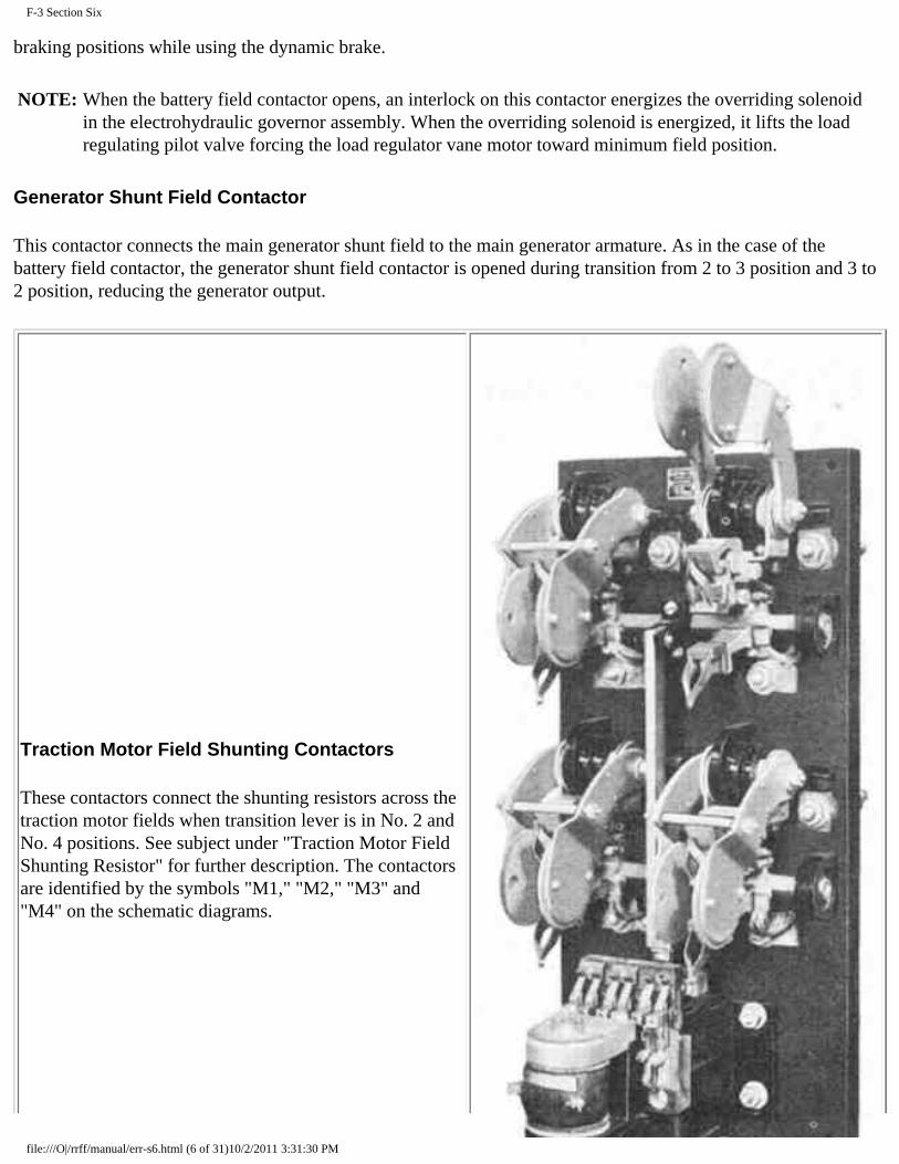
F-3 Section Six
braking positions while using the dynamic brake.
NOTE: When the battery field contactor opens, an interlock on this contactor energizes the overriding solenoid in the electrohydraulic governor assembly. When the overriding solenoid is energized, it lifts the load regulating pilot valve forcing the load regulator vane motor toward minimum field position.
Generator Shunt Field Contactor
This contactor connects the main generator shunt field to the main generator armature. As in the case of the battery field contactor, the generator shunt field contactor is opened during transition from 2 to 3 position and 3 to 2 position, reducing the generator output.
Traction Motor Field Shunting Contactors
These contactors connect the shunting resistors across the traction motor fields when transition lever is in No. 2 and No. 4 positions. See subject under "Traction Motor Field Shunting Resistor" for further description. The contactors are identified by the symbols "M1," "M2," "M3" and "M4" on the schematic diagrams.
file:///O|/rrff/manual/err-s6.html (6 of 31)10/2/2011 3:31:30 PM

F-3 Section Six
Traction Motor Field Shunting Contactors Fig. 6-3
Field Loop Contactor
The field loop contactor is energized when the transition lever is moved to the "OFF," "B" and succeeding braking positions. It operates in conjunction with interlocks on top of the cam-switch to place the dynamic brake control rheostat and resistors, and the unit selector switch and its resistors, in series with the field loop circuit.
Dynamic Brake Contactors
The dynamic brake contactors connect the four traction motor fields in series with each other and to the main generator during dynamic braking. The braking contactors close when the transition lever is moved to the "OFF" position and remain closed when the braking lever is in "B" and succeeding braking positions.
Dynamic Brake Contactors Fig. 6-4
file:///O|/rrff/manual/err-s6.html (7 of 31)10/2/2011 3:31:30 PM

F-3 Section Six
Traction Motor Pneumatic Contactors
These contactors change the traction motor connections from series-parallel to parallel, or vice versa. They operate on air pressure through magnet valves.
A.C. Motor Contactors
There are four of these contactors in the electrical control cabinet of each unit. Operation of each radiator cooling fan motor is individually operated by its contactor which in turn is controlled through the thermostat switch. (Also see "Operation of Cooling System" Section 3, and "Transfer Relays" in this section.)
Each of the A.C. fan motor contactors is provided with a thermal overload protective device. For information on operation of this protective device see "Locomotive Protective Devices," Section 2.
Fuel Pump Contactor
The fuel pump contactor is located in the engine control and instrument panel. All fuel pump contactors throughout the locomotive are controlled by the fuel pump master switch on the control push-button switch box. When the contactor in any unit is closed, the fuel pump can be controlled individually by a toggleswitch mounted on the engine control and instrument panel. Electricity is supplied through this contactor for operating the shutter magnet valves and cooling fan contactors under control of the thermostat switch.
Load Regulator and Pilot Valve Operation
The load regulator is divided into two sections: the pilot valve which is incorporated in the engine governor assembly, and a self-contained unit in a structural steel frame, consisting of an hydraulic vane-type motor attached to a commutator-type rheostat.
The load regulator is used to vary the load on the Diesel engine for any given engine speed, thereby allowing the engine to determine the load which it can carry. If the engine governor demands more fuel than a predetermined setting, the load regulator reduces the load on the engine by reducing the field excitation of the main generator, and vice versa. In this way, overloading the engine is prevented if some of the cylinders should become inoperative.
A solenoid (O) in the governor is energized during the time interval in which transition from 2 to 3 or 3 to 2 is taking place. The operation of this solenoid causes the load regulator to move toward minimum field in this period. This action makes it unnecessary to reduce the throttle to Run 6 while the 3 to 2 and 2 to 3 transitions are being made.
Voltage Regulator
The voltage regulator maintains the auxiliary generator voltage at a constant of 74 volts throughout the operating speed range of the engine. This keeps the battery charged and provides a constant source of excitation for the main generator during locomotive operation.
file:///O|/rrff/manual/err-s6.html (8 of 31)10/2/2011 3:31:30 PM

F-3 Section Six
A defective voltage regulator will be evidenced by excessive fluctuation of the ammeter in the electrical control cabinet. A defective auxiliary generator will affect the battery charging rate and the excitation of the main generator.
Ground Protective Relay Fig. 6-5
Ground Protective Relay
If a ground occurs in the high voltage system, this relay will open the battery field and main generator shunt field contactors and bring the engine to idle except when the throttle is in the 5th or 6th position, and in this event the engines will be stopped. Should this occur, isolate the engine and reset the relay by means of the reset lever. Place the engine "back on the line." If the relay repeatedly opens when the engine speed is increased, isolate that power plant. A knife switch in the electrical control cabinet renders the ground protective relay inoperative when opened. The switch is provided for use during certain electrical tests during maintenance operations. It should not be opened on the road except under circumstances authorized by definite instructions issued by the particular railroad on which the locomotive is operating.
Reverse Current Relay
This relay prevents the battery current from "motoring" the auxiliary generator by opening the battery charging contactor when the auxiliary generator voltage drops below the battery voltage.
Parallel Relay
file:///O|/rrff/manual/err-s6.html (9 of 31)10/2/2011 3:31:30 PM

F-3 Section Six
This relay is energized when the transition lever is in the No. 3 and No. 4 positions, and operates in conjunction with the time delay relay to close the traction motor parallel (P1, P2, P3, P4) contactors. It also operates in conjunction with the main generator shunt field and battery field contactors to cause the latter to open during transition from No. 2 to No. 3 position and No. 3 to No. 2 position.
Brake Relay
This is a double-acting relay, the function of which is to establish the "TOW" position of the cam-switch and partially complete the circuit to the braking contactors when energized.
When de-energized, this relay establishes the "Motor" position of the cam-switch and partially completes the circuit to the traction motor contactors.
The relay is energized when the transition lever is in "OFF," "B," or succeeding braking positions.
Dynamic Brake Warning Relay
This relay operates the dynamic brake warning light on the instrument panel in the cab. For information, refer to "Dynamic Brake Warning Light and Relay" under the subject "Locomotive Protective Devices," Section 2.
No A.C. Voltage Relay
This relay is in the alternator circuit and should the A.C. voltage fail, the alarm bell rings and the "No A.C. Voltage" warning light (blue light) goes on. The engine speed will return to idle except when the throttle is in the 5th or 6th position, and in this event the engines will be stopped.
Transfer Relays
There are two of these relays in each unit. When oper ated, these relays establish a circuit to the radiator cooling fan motor contactors. One relay controls fan motors Nos. 1 and 4, the other controls fan motors Nos. 2 and 3.
The sequence of operation of the four cooling fans is changed by operation of the transfer relays. This is provided so that all four fans will get approximately equal work to avoid the probability of the last fan never working.
Wheel Slip Relays
There are two wheel slip relays (WSR-1 and WSR-2). Each relay has two normally open contacts. In the event of a pair of wheels slipping, the coil connected to that motor will be energized. One of the contacts will light the wheel slip light and the other will deenergize the main generator shunt field operating coil, thereby dropping generator shunt field and battery field. Power output will be reduced momentarily until slipping stops.
When wheels slip, it is necessary to reduce the position of the throttle until the wheels stop slipping and then reapply the power by opening the throttle gradually. The relay will not operate if a pair of wheels should stop during dynamic braking. If necessary to use sand, it should be applied (sparingly) only after the wheels stop
file:///O|/rrff/manual/err-s6.html (10 of 31)10/2/2011 3:31:30 PM

F-3 Section Six
slipping.
Alarm Signal Relay
This relay operates with the signal lights ("Hot Engine," "Boiler Off" and "Low Oil Pressure") to ring the alarm bells throughout the locomotive.
Isolation Switch
The isolation switch is located on the engine control and instrument panel. Its purpose is to open and close the control circuit of the unit as occasion demands. When starting the Diesel engine, this switch must be in the "START" position. After engine is running, move switch to "RUN" position. This will connect the control circuit of the unit to the engineer's controller. If it becomes necessary to isolate the unit, the isolation switch should be moved to the "START" position. This will bring the engine to idle and cut off the power of this unit. See subject under "Isolating and Stopping an Engine While Under Power," Section 2 of this manual.
Unit Selector Switch
The unit selector switch is a four-position switch located to the left of the engineer's instrument panel. Its purpose is to provide a means of keeping the excitation of the main generator fields at the same relative value while using the dynamic brake, regardless of number of units making up the locomotive. This switch should NEVER be moved when using the dynamic brake, or when an engine is "off the line" or shut down. The switch must be set to correspond with the number of units making up the locomotive before leaving the maintenance point.
Cam-Switch
This switch is a cam. type, air-operated switch controlled by magnet valves. It has sixteen pairs of main contacts, a rotary and a cam interlock assembly on top of the cam switch. When in the "Motor" position, it connects the traction motor armatures in series with their respective fields, and disconnects the braking grids from the motor armatures. When in the "Tow" position, it disconnects the traction motor armatures from their fields, and connects a braking grid across each armature.
file:///O|/rrff/manual/err-s6.html (11 of 31)10/2/2011 3:31:30 PM

F-3 Section Six
Cam-Switch Fig. 6-6
Pneumatic Control Switch
The pneumatic control switch is an air-operated electric switch located on the right-hand side of the cab, below the window. The purpose of this switch is to reduce the power of the locomotive by bringing the speed of the engines to idle when certain air brake applications take place (see above subject under "Locomotive Protective Devices," Section 2). The switch has a manual reset button which must be pulled out after the air brakes have been released. This switch is referred to as the "PC" switch. The effect of the "PC" switch on the various circuits of the locomotive can be found in the wiring diagrams.
Main Battery Switch
This switch isolates all circuits from the battery except the external charging receptacle. The switch should be opened when locomotive is left standing with engines shut down, or when charging battery from an external source.
file:///O|/rrff/manual/err-s6.html (12 of 31)10/2/2011 3:31:30 PM

F-3 Section Six
Thermostat Switch
Engine water temperature control is automatic and is obtained by automatic operation of the shutters and each of the four cooling fans separately.
The automatic temperature control system consists of a thermal element with its contact block and fingers, four contactors, two transfer relays, two sets of shutters, and four cooling fans driven by 12 HP A.C. motors.
The thermal element with its contact block and fingers is located in the engine water outlet pipe, the control relays and contactors are located in the electrical control cabinet, and the four cooling fans in the main hatch over the engine.
When the engine water discharge temperature reaches 166 ° F., the shutters on both sides of the unit open automatically. Thereafter, with approximately each 3 ° F. rise in water temperature, one fan will be started as required until, if necessary, all four fans are running. When the temperature of the cooling water drops, the fans will not cut out one by one, but will remain running until the water temperature drops to 163° F., when all four fans will shut off and the shutters will close simultaneously.
Auxiliary Generator Switch
One switch is located in the electrical control cabinet of each unit. All battery charging equipment of one power plant (auxiliary generator, reverse current relay, battery charging contactor, alternator field circuit and voltage regulator) is isolated from the battery when this switch is open
Lighting Switch
The lighting circuits of the locomotive are connected to this double-pole single-throw switch which is located on the distribution panel of the electrical control cabinet.
Engine "Start" and "Stop" Switches
These switches are located on the engine control and instrument panel. They will operate only when the isolation switch is in "START" position and control switch, in the control push-button switch box, is closed. The "START" switch operates the starting contactors. The "STOP" switch energizes the "D" solenoid in the electro-hydraulic governor control stopping the engine.
Fuel Pump Switch
This is a push-button switch located in the control pushbutton switch box at the right of the engineer. The fuel pump contactors throughout the locomotive are controlled by this master switch. When this switch is closed, each fuel pump motor can be individually controlled by a toggleswitch located on the engine control and instrument panel.
Control Knife Switch
file:///O|/rrff/manual/err-s6.html (13 of 31)10/2/2011 3:31:30 PM

F-3 Section Six
This switch is located on the distribution panel and controls battery power to the relays, contactors, etc., in the control circuit.
Fuse Test Switch
The fuse test switch is located on the distribution panel and is connected in parallel with the fuse test blocks. To test a fuse, turn fuse test switch on to light lamp, place fuse to be tested across fuse test blocks and turn switch off. If lamp goes out, fuse is blown. The lamp socket can also be used to check a lamp.
Engine Room Light Switches
The two (three-way) switches operate independently of each other to turn the engine room lights on or off. If the lights are on, either switch will turn them off, and vice versa.
Control Push-Button Switch Box
For information refer to Section 1.
Low Oil Pressure Alarm Switch
For information refer to "Governor Safety Control," Section 2.
Lube Oil Suction Alarm Switch
For information refer to "Governor Safety Control," Section 2.
Ground Protective Relay Switch
This switch opens the circuit to the operating coil of the ground protective relay. See paragraph on "Ground Protective Relay" in this section.
Engine High Temperature Alarm Switch
For information, refer to "Locomotive Protective Devices," Section 2.
Battery Charging Resistor
This resistor is connected in series with the auxiliary generator. It prevents excessive battery charging rate.
Generator Shunt Field Discharge Resistor
This resistor shunts the main generator shunt field to reduce the high induced voltage when generator shunt field contactor opens.
file:///O|/rrff/manual/err-s6.html (14 of 31)10/2/2011 3:31:30 PM

F-3 Section Six
Generator Shunt Field Resistor
This resistor is connected in series with the main generator shunt field. Its purpose is to regulate the shunt field current.
Battery Field Discharge Resistor
This resistor shunts the main generator battery field to dissipate the high induced voltage when the circuit to the battery field is opened.
Traction Motor Field Shunting Resistor
This resistor is connected across the traction motor fields when the traction motor shunt contactors close.
Dynamic Brake Control Rheostat
The brake control rheostat is located in the bottom of the controller and operates between "B" and maximum braking position of the dynamic brake control lever, to vary the resistance in series with the field loop circuit. This will vary the braking effort of the locomotive.
ELECTRICAL CONTROL CABINET
The electrical control cabinet contains the following high and low voltage equipment. The high voltage equipment in this cabinet should never be worked on when the unit is in operation, as the voltages produced by the main generator are dangerous.
High Voltage
● 1. Wheel slip relay resistors. ● 2. Brake contactors-3-pole. ● 3. Field loop contactor. ● 4. Motor field shunting contactors-4-pole. ● 5. Transition meter shunt. ● 6. Ground relay knife switch. ● 7. Ground protective relay. ● 8. Wheel slip relays. ● 9. Parallel relay. ● 10. Shunt field discharge resistor. ● 11. Shunt field contactor. ● 12. Shunt field contactor resistor. ● 13. Reverser. ● 14. Braking relay. ● 15. Cam-switch. ● 16. Pneumatic contactors. ● 17. Brake warning relay.
file:///O|/rrff/manual/err-s6.html (15 of 31)10/2/2011 3:31:30 PM

F-3 Section Six
Low Voltage
● 1. Battery field contactor. ● 2. Auxiliary generator ammeter. ● 3. Reverse current relay. ● 4. Auxiliary generator knife switch. ● 5. Battery charging contactor. ● 6. Battery charging fuse-150-amp. ● 7. Auxiliary generator field fuse-30-amp. ● 8. Battery field fuse-80-amp. ● 9. Signal relay. ● 10. Startinq contactors. ● 11. Voltage regulator. ● 12. Battery field discharge resistor. ● 13. Braking control resistors. ● 14. No AC voltage relay.
file:///O|/rrff/manual/err-s6.html (16 of 31)10/2/2011 3:31:30 PM

F-3 Section Six
Low Voltage Panel Fig. 6-7
Distribution Panel Fig. 6-8
Distribution Panel
● 1. Main batterv switch. ● 2. Master control knife switch and 80-ampere control fuse. ● 3. Master light switch and 30-ampere fuse. ● 4. Automatic train control-speed governor knife switch, and 60-ampere
file:///O|/rrff/manual/err-s6.html (17 of 31)10/2/2011 3:31:30 PM

F-3 Section Six
● 5. Ammeter (battery charge). ● 6. Starting fuse-400-amp. ● 7. Fuse test blocks and test light. ● 8. External charging fuse. ● 9. Steam generator fuse. ● 10. Other fuses on low voltage control and lighting circuits.
A.C. Circuit
● 1. Four cooling fan motor contactors. ● 2. Two transfer relays. ● 3. Relay for thermostat switch. ● 4. "No A.C. Voltage" relay. ● 5. Alternator field fuse-35-ampere.
Ammeters
The ammeter in the electrical control cabinet indicates auxiliary generator output and does not necessarily agree with the ammeter on distribution panel. The ammeter on the distribution panel shows net charge or discharge through the battery, except starting current or current from an external charging source.
Speed Recorder
The speed recorder is an hydraulic operated speedometer with recording tape. It is driven from an axle on the No. 1 truck of the "A" unit, by a flexible cable. A micro-switch inside the recorder cover operates at a predetermined setting, acting as a maximum speed governor.
Electro-Hydraulic Governor Control Solenoids
This assembly consists of four solenoids-designated as "A," "B," "C," and "D." Various combinations of these solenoids control engine speed in accordance with throttle position. The following chart indicates solenoid combinations and engine speeds at all throttle positions.
A fifth solenoid "O" is included in the governor assembly which affects engine loading only and does not affect engine speed. When this solenoid is energized, it causes the lifting of the load regulating pilot valve, thus forcing the vane motor toward minimum field position.
ENGINE SPEED CHART
THROTTLE ENGINE POSITION SPEED RPM SOLENOIDS ENERGIZED A B C D
file:///O|/rrff/manual/err-s6.html (18 of 31)10/2/2011 3:31:30 PM

F-3 Section Six
STOP * 0 IDLE 275 1 275 2 * 350 3 * 425 4 * * 500 5 * * * 575 6 * * * * 650 7 * * 725 8 * * * 800
"ER" Relay
This relay controls the current supply to the "A," "B," and "C" solenoids of the electro-hydraulic governor control. De-energizing this relay will stop the engine if the throttle is in Run 5 or Run 6, or bring the engine to idle in any other throttle position.
Traction Motor Control Circuit Explanation
A sequence test of the control circuit should be made by the maintainer before dispatching locomotive from maintenance point.
A definition and description of transition is given in Section 2 of this manual. The following explanation describes what takes place during transition.
FORWARD TRANSITION (Train Speed Increasing)
After engines have been started and placed "on the line," the following must be closed before the locomotive will move:
Generator field switch. Transition lever (in No. 1 position). Reverse lever (in forward or reverse). Reverser (in forward or reverse). Starting contactor interlocks. Ground protective relay interlock.
1. No. 1 Transition Position (Series-Parallel):
The following operations occur when the transition lever is in No. 1 position and throttle is moved from "IDLE" to Run 1-
file:///O|/rrff/manual/err-s6.html (19 of 31)10/2/2011 3:31:30 PM

F-3 Section Six
● a. Brake relay moves to "power" position. ● b. Cam-switch moves to "motor" position. ● c. Braking contactors open. ● d. "SH" and "BF" contactors close. ● e. "S" contactors close (S14 and S23).
2. No. 2 Transition Position (Series-Parallel-Shunt):
When transition lever is moved to No. 2 position--
a. "M" contactors (Ml, M2, M3, M4) close, thus shunting the main field of each traction motor.
3. No. 3 Transition Position (Parallel):
When the transition lever is moved to the No. 3 position-
● a. Parallel relay (PR) closes. ● b. Shunt field contactor (SH) opens. ● c. Battery field contactor (BF) opens. ● d. Motor shunting contactors (M) open. ● e. Parallel contactor (PI) closes. ● f. Series contactor (S 14) opens. ● g. Parallel contactor (P4) closes. ● h. Parallel contactor (P2) closes. ● i. Series contactor (S23) opens. ● j. Parallel contactor (P3) closes. ● k. Generator shunt field and battery field contactors (SH and BF) close.
4. No. 4 Transition Position (Parallel-Shunt):
When the transition lever is moved to the No. 4 position
a. Motor field shunting contactors (M) close.
BACKWARD TRANSITION (Train Speed Decreasing)
As train speed decreases due to a grade, the transition lever must be moved in accordance with transition meter indication to prevent overload of the electrical equipment. See Section 2 of this manual for operating details.
1. Parallel-Shunt to Parallel Transition:
The following operations occur when the transition lever is moved from No. 4 to No. 3 position
file:///O|/rrff/manual/err-s6.html (20 of 31)10/2/2011 3:31:30 PM
F-3 Section Six
a. "M" contactors open.
2. Parallel to Series-Parallel-Shunt Transition:
When transition lever is moved from No. 3 to No. 2 position
● a. Parallel relay (PR) opens. ● b. "SH" and "BF" contactors open. ● c. "Pl" contactor opens. ● d. "S14" contactor closes. ● e. "P4" contactor opens. ● f. "P2" contactor opens. ● g. "S23" contactor closes. ● h. "P3" contactor opens. ● i. "SH" and "BF" contactors close. ● j. "M" contactors close.
3. Series-Parallel-Shunt to Series-Parallel Transition:
When transition lever is moved from No. 2 to No. 1 position
● a. "M" contactors open. ● b. "SH" and "BF" contactors remain closed. ● c. "S14" and "S23" contactors remain closed:
4. Series-Parallel to "OFF" Transition:
When throttle is moved to "IDLE" position and transition lever to "OFF"
● a. "S14," "S23," "SH" and "BF" contactors open. ● b. Braking relay moves to dynamic braking position, camswitch moves to "TOW" position, braking
contactors and field loop contactors close.
AUTOMATIC TRANSITION
Automatic transition was put onto the F3 locomotive for the purpose of making a smoother transition and also to insure transition being made at the proper time with the throttle in Run 8 position. This tends to relieve the engineman of these duties but it does not relieve him of the responsibility of knowing that the transition takes place at the proper time.
There will be times when it is desirable to forestall a forward transition. For instance, a locomotive pulling a train on an ascending grade in No. 2 position (series-parallel-shunt). There may be a short level spot where the locomotive speed will increase just enough to cause forward transition to No. 3 position (parallel). About this
file:///O|/rrff/manual/err-s6.html (21 of 31)10/2/2011 3:31:30 PM

F-3 Section Six
same time the grade starts up again. The locomotive speed is too slow to stay in parallel, so backward transition will occur, placing locomotive back in No. 2 position (series-parallel-shunt).
This can be prevented by placing the transition lever in No. 2 position, thus forestalling any undesired forward transition. Transition will never advance further than the position in which the transition lever is placed.
Forward Transition Relay
The forward transition relay FTR is connected across the main generator leads with three 7200 ohm variable resistors in series with this relay. This relay is operated by main generator voltage. It is set to pick up at 930 volts and is set to drop out at 860 to 900, 675, and 580 volts. Varying amounts of resistance cut out of this circuit during different steps of transition account for the different dropout values.
Backward Transition Relay
The backward transition relay BTR is closed at all times except during backward transition. It is connected across the meter terminals of a 2000 ampere shunt. This shunt carries full main generator current. The relay is actuated by the difference of potential between these terminals. A movable arm in this relay starts to move when main generator current reaches 1820 amperes. This arm moves farther as the current increases, up to 2100 amperes, where the arm has reached its extreme right hand position, closing a circuit, allowing control current to flow through two coils of opposite polarity (thereby opposing each other), opening KP relay. The KY relay is normally closed when the locomotive is under power.
KP Relay
The KP relay is actuated by BTR, as stated above. When this relay is closed a circuit is established on the negative side of M contactor, MR, PM, TD, and PR relays.
PM Relay
The only function of PM relay is to establish a circuit to M contactor when making automatic transition from 1 to 2, with the transition lever in No. 3 position. As no current flows through M wire with the transition lever in this position, M contactor is energized by control current from GF wire passing through closed PM interlock AB, through closed BF interlock GH to the actuating coil of M contactor.
Time Delay Relay
A time delay relay TD is energized through closed PR interlock WX, closed FTR interlock EF and closed N interlock EF in series with each other. It is held closed after FTR opens through closed PR interlock WX, closed PM interlock CD and closed M interlock EF. This relay establishes a circuit energizing PR relay when FTR interlock CD is closed. It takes six seconds for this relay to close.
Parallel Relay
A parallel relay PR is energized through closed FTR interlock CD and closed TD interlock AB in series with each
file:///O|/rrff/manual/err-s6.html (22 of 31)10/2/2011 3:31:30 PM
F-3 Section Six
other. When PR is energized, AB interlock establishes a holding circuit for PR. CD interlock is in series with closed battery field contactor interlock EF and closed M interlock AB to energize P1 contactor. EF interlock is open in shunt field contactor circuit. GH, JK interlocks are closed in GS and GN circuit of the FTR. NP interlock is closed in shunt field contactor circuit. QR interlock is open. WX interlock is open. YZ interlock is open, inserting resistance into the BTR circuit.
Time Delay Backward Relay
The time delay backward relay TDB is energized by M contactor interlocks in both the energized and de-energized position. TDB takes a minimum of 15 seconds to close. When TDB is de-energized, AB interlock is closed, establishing a negative circuit for M contactor, MR, PM, TD and PR relays, when KP interlock FH is open. TDB interlock CD is closed, establishing a circuit through closed M interlocks LM and NP in series when closed PR interlocks GH and JK, shorting resistance out of FTR circuit. When this relay is energized, these circuits are open.
An overriding cylinder is built into the engine governor and is actuated by a solenoid ORS which is energized by closed BF interlock CD during transition. When this solenoid is energized, high pressure oil from the governor accumulator is admitted to the cylinder, raising a piston which in turn raises the load regulator pilot valve 1/a". This causes the load regulator vane motor arm to start toward minimum field, reducing the BF excitation current to the main generator field, thus preventing engine overload immediately after transition. When this solenoid is de-energized, a spring returns the load regulator pilot valve to its normal position and the vane motor arm starts back toward maximum field, loading up the engine.
The M contactor is energized through closed FTR interlock AB and closed BF interlock GH in series with each other. It is also energized by closed PM interlock AB when the transition lever is placed in No. 3 position. This contactor closes the motor shunting contacts M1, M4, M2, and M3 when energized. It also establishes a circuit in both the energized and the de-energized position, energizing TDB.
The MR relay is in parallel with M contactor, both being energized and de-energized at the same time. This relay places resistance in series with the transition indicating meter when energized and shorts out this resistance when de-energized.
The purpose of this is to prevent backswing of the needle toward a higher reading when M contactors are closed, and allows the use of a simple dial on the transition indicating meter. The MR relay is energized whenever the M contactors are closed. No further mention of the MR relay is made under automatic transition.
In the transition sequence which follows, speeds indicated are for a locomotive equipped with 62:15 gear ratio. The speeds will necessarily vary with different gear ratios.
Forward Transition - 1 to 2 Position
Assuming engine is running, cutout switches open (in automatic position), all control switches in, reverser in either forward or reverse position, transition lever in No. 4 position. Throttle is open and all contactors closed to move locomotive in series-parallel. Main generator current flows from GS1, through No. 1 traction motor, through closed S14 contactor, through No. 4 traction motor, to GN4.
file:///O|/rrff/manual/err-s6.html (23 of 31)10/2/2011 3:31:30 PM

F-3 Section Six
Main generator current also flows from GS2 through No. 2 traction motor, through closed S23 contactor, through No. 3 traction motor, to GN3.
The actuating coil of the forward transition relay FTR is connected across the main generator so as to receive full generator voltage. The circuit is through GS, three 7200 ohm resistors in series, the actuating coil FTR and GN.
The KP relay is energized when the throttle is opened to No. 1 position. Current flows from generator field switch through closed isolation switch, through adjustable 75 ohm resistor, through closed BTR contact point LC, through two coils in series, to close KP relay. KP relay closes, establishing a holding circuit through one coil, holding relay closed. KP interlock FH closes. This interlock forms a path for current coming from M contactor, MR, PM, TD, and PR relays to the negative lead.
At a locomotive speed of approximately 19 MPH the main generator voltage will have risen to about 930 volts. At 930 volts the forward transition relay FTR closes.
With the transition lever in No. 4 position, both M and P wires are hot, 74 volt control current. As FTR closes, control current flows from M wire through closed FTR interlock AB, through closed BF interlock GH, to the actuating coil of M contactor, closing M1, M4, M2, and M3 contacts. As M contactor closes, M interlock CD closes, holding M contactor energized.
Control current flows from P wire through closed PR interlock WX, through closed FTR interlock EF, to actuating coil of PM relay. As PM closes, PM interlock CD closes, holding this relay closed. Control current flows through closed M interlock EF to TD actuating coil. TD closes after a minimum of 6 seconds time delay.
As the motor shunting contactors close, the main generator voltage will drop and FTR opens, opening FTR interlocks AB, CD, and EF. The dropout value of FTR is approximately 860 to 900 volts.
M contactor stays energized because M interlock CD has closed, allowing control current to flow from M wire through closed PR interlock QR and M interlock CD, establishing a holding circuit.
PM relay stays closed as control current now flows through closed PM interlock CD, in series with closed PR interlock WX.
PR relay does not close during 1 to 2 transition. It is true that the FTR interlock CD had been closed after FTR picked up, but TD has a time delay of at least 6 seconds, so by the time TD actually closed and TD interlock AB closed, FTR had dropped out, opening interlock CD, preventing PR from closing.
TDB relay closes when battery field closes with M contactor in energized or de-energized position after a 15 second delay. Opening or closing M contactor momentarily drops TDB out. This relay functions only to delay backward transition under certain conditions.
Locomotive should now be running in series-parallel-shunt (No. 2 position) above 19 MPH. M, S14 and S23 contactors are closed. PM, TD and KP are closed. TDB is closed. FTR is open.
Forward Transition - 2 to 3 Position
file:///O|/rrff/manual/err-s6.html (24 of 31)10/2/2011 3:31:30 PM

F-3 Section Six
Locomotive is now in series-parallel-shunt. As locomotive speed reaches about 25 MPH, main generator voltage will again be up to 930 volts and FTR will close.
As FTR closes, FTR interlock CD closes, allowing control current to flow from P wire through this closed interlock, through closed TD interlock AB to PR relay actuating coil, PR closes. PR interlock EF opens, opening shunt field and battery field contactors and TDB relay.
As battery field contactor opens, BF interlock CD closes, energizing overriding cylinder solenoid ORS. When this solenoid is energized, high pressure oil from the governor accumulator raises a piston which in turn raises the load regulator pilot valve 1/s". The load regulator vane motor arm immediately starts to move towards the minimum field side to prevent overloading the engine immediately after transition. The amount of movement of this arm will depend on the position of the compensating screw in the load regulator pilot valve assembly.
BF interlock GH opens, opening M contactor. M contactor opens Ml, M4, M2, and M3 contacts. PR interlock AB closes, holding PR closed. PR interlocks GH and JK close in the circuit that shunts out resistance to FTR, but no current can. go through at this time because M interlocks LM and NP are open. PR interlock WX opens, opening PM and TD relays. Neither of these can close because all interlocks in the circuit are open. PR interlock YZ opens, putting .55 ohm resistor in series with BTR.
As the main generator voltage drops below 860 to 900 volts, due to opening of battery and shunt field circuits.
FTR opens.
PR interlock CD closes, allowing control current to pass through closed BF interlock EF, through closed M interlock AB, closing P1 contactor.
P1 interlock CD now closes, holding P1 closed. P1 interlock AB opens, opening S14 contactor.
S14 interlock AB closes, allowing current to flow through closed P1 interlock EF and S14 interlock AB, closing P4 contactor.
P4 interlock AB opens in braking contactor coil B circuit. This circuit is only used during dynamic braking. P4 interlock CD closes, closing P2 contactor. P2 interlock AB opens, opening S23 contactor. S23 interlock AB closes, closing P3 contactor. P2 interlock CD opens in B circuit. P3 interlock AB. opens in shunt field contactor circuit. P3 interlock CD closes in circuit to P4 contactor. P3 interlock EF closes in shunt field contactor circuit, allowing control current to flow through closed PR interlock NP, through closed P3 interlock EF, through a 50 ohm resistor, closing shunt field contactor.
Shunt field contactor interlock AB closes, closing battery field contactor and TDB which takes at least 15 seconds to close. When TDB relay is closed, TDB interlock AB opens. No change takes place in this circuit, as KP interlock FH is closed, maintaining the negative circuit for M contactor, MR, PM, TD, and PR relays. TDB interlock CD opens. No change takes place in this circuit at this time as no current was flowing through because M interlocks LM and NP are open.
As battery field contactor closes, BF interlock CD opens, deenergiznig the overriding cylinder solenoid. A spring brings the pilot valve back to its normal position, and the -7 vane motor arm can now go back toward maximum
file:///O|/rrff/manual/err-s6.html (25 of 31)10/2/2011 3:31:30 PM

F-3 Section Six
field to load up the engine. Engine speed is not reduced during transition.
We now have P1, P2, P3, and P4 contactors closed. S14, S23, and M contactors and Ml, M4, M2, and M3 contacts are open. PM and TD relays are open and KP and PR relays are closed. Locomotive should now be running in parallel (No. 3 position) above 25 MPH.
Forward Transition - 3 to 4 Position
Locomotive is in parallel position. When locomotive speed reaches approximately 52 MPH, main generator voltage again reaches 930 volts and FTR closes. FTR interlock AB closes, closing M contactor. MR relay is energized, opening a circuit, putting resistance in series with transition indicating meter. As M contactor closed, it closed M1, M4, M2, and M3 contacts, shunting the traction motor fields.
A circuit is now completed through closed M interlocks LM and NP, closed PR interlocks GH, JK, and closed TDB interlock CD. This shorts out resistance in the FTR circuit. As the motor shunting contactors close, main generator voltage will drop, but due to the fact that resistance has been cut out of FTR circuit, the dropout voltage of this relay is now approximately 580 volts. The main generator voltage does not drop quite this low, so FTR stays closed.
TDB closes 15 seconds later, opening TDB interlock CD, adding more resistance to FTR coil circuit and changing FTR dropout voltage to 675. Since the main generator voltage has built up somewhat during the 15 second time delay, FTR stays closed.
P1, P2, P3, P4 and M contactors and M1, M4, M2, and M3 contacts are closed. MR relay is energized putting resistance into meter circuit. PR, TDB and KP relays are closed. PM and TD relays are open. FTR is closed.
Locomotive is now running in parallel-shunt (No. 4 position) above MPH.
Backward Transition - 4 to 3 Position
Locomotive is now in parallel-shunt (No. 4 position) running above 52 MPH. On an ascending grade, locomotive speed will decrease. Main generator voltage will start to drop as the amperes go up. At a locomotive speed of about 45 MPH main generator voltage will drop below the 675 volt dropout value of FTR. FTR opens.
As FTR drops out, FTR interlock AB opens, breaking circuit to M contactor. M contactor opens M1, M4, M2, and M3 contacts. Opening M contactor causes TDB to cycle (open and close).
P1, P2, P3, and P4 contactors are closed. S14, S23, and M contactors are open. PM, TD, and FTR relays are open. PR, KP and TDB relays are closed. Locomotive is now back to parallel, running between 23 and 45 MPH.
Backward Transition - 3 to 2 Position
Locomotive is now running in parallel (No. 3 position) on an ascending grade. As the locomotive speed decreases to about 23 MPH, the generator current has gone up to 2100 amperes. PR interlock YZ is open, inserting resistance into the BTR circuit, so this relay now has a pickup value of 2100 amperes. The BTR is actuated by the
file:///O|/rrff/manual/err-s6.html (26 of 31)10/2/2011 3:31:30 PM

F-3 Section Six
difference of potential between terminals on a 2000 ampere shunt that carries full generator current.
A movable arm in BTR opens the circuit LC in the relay when the main generator current has reached about 1820 amperes. No change takes place as this circuit is opened, because a circuit has already been established through closed KP and one of the coils, holding this relay closed. As the main generator current reaches 2100 amperes, this arm will have gone over to its extreme right-hand position, closing circuit HC.
Current now flows from GF wire through two coils in opposite directions. Due to opposite polarity in these coils, one opposes the other, opening KP relay. KP interlock FH opens, breaking the negative circuit, opening PR relay.
PR interlock NP opens, dropping out shunt field and battery field contactors, and de-energizing TDB. As battery field contactor opens, BF interlock CD closes, energizing the overriding cylinder solenoid ORS, raising the load regulator pilot valve '/s". This causes the load regulator vane motor arm to start toward minimum field. PR interlock CD opens, opening P1 contactor. P1 interlock AB closes, closing S14 contactor. S14 interlock AB opens, opening P4 contactor. P4 interlock CD opens, opening P2 contactor. P2 interlock AB closes, closing S23 contactor. S23 interlock AB opens, opening P3 contactor.
Control current now flows through closed PR interlock EF and closed P3 interlock AB, closing the generator shunt field and battery field contactors, and energizing TDB. BF interlock CD opens, deenergizing overriding cylinder solenoid ORS. The load regulator pilot valve returns to its normal position and the vane motor arm can now go back toward maximum field. Engine speed is not reduced during transition.
As generator amperes fall below 1300 (the dropout value of BTR) BTR closes and the movable arm in the relay opens HC circuit and closes LC circuit, closing KP relay. KP interlock FH closes, establishing the negative path for the current from M contactor, MR, PM, and TD relays.
At this point of the transition, the locomotive has reverted to No. 1 position, because the motor shunting contacts have not closed as yet. It is possible here for the locomotive to remain in No. 1 position, if a condition should arise that would cause a rapid deceleration in locomotive speed.
Normally, however, the generator voltage rises to 930 volts and transition takes place 1 to 2 as in normal forward transition.
As M contactor is energized, TDB is opened, closing TDB interlock AB, closing an additional negative circuit for M contactor. This prevents M contactor from opening if a surge of main generator current should operate BTR, opening KP relay.
PR is again prevented from closing because FTR interlock CD opens before TD interlock AB closes. Contactors P1, P2, P3, P4, and M are open. M 1, M4, M2, and M3 contacts are closed. PM, TD, KP, BTR, and TDB are closed. PR and FTR relays are open.
Locomotive is now in series-parallel-shunt (No. 2 position and running less than 23 MPH.
Backward Transition - 2 to 1 Position
file:///O|/rrff/manual/err-s6.html (27 of 31)10/2/2011 3:31:30 PM
F-3 Section Six
Locomotive is running in series-parallel-shunt (No. 2 position) on an ascending grade, less than 23 MPH. As locomotive speed decreases to about 18 MPH the ampere output of the generator rises to 1500 amperes.
The pickup value of BTR has been changed to 1500 amperes because PR interlock YZ has closed, shorting out the resistance in series with BTR.
The movable arm in BTR moves to the right as BTR opens, opening LC circuit and closing HC circuit, putting current through two opposing coils, opening KP relay. KP interlock FH opens, deenergizing M contactor, and M contactor opens M1, M4, M2, and M3 contacts.
As the motor shunting contacts M1, M4, M2, and M3 open, the generator current falls below 1300 amperes (the dropout value of BTR) and BTR closes, closing KP relay.
S14 and S23 contactors are closed. P1, P2, P3, P4, and M contactors and M1, M4, M2, and M3 contacts are open. PM, TD, FTR, and PR relays are open. BTR, TDB and KID relays are closed.
Locomotive is now in series-parallel (No. 1 position) running less than 18 MPH.
file:///O|/rrff/manual/err-s6.html (28 of 31)10/2/2011 3:31:30 PM

F-3 Section Six
LEGEND OF ELECTRICAL EQUIPMENT
file:///O|/rrff/manual/err-s6.html (29 of 31)10/2/2011 3:31:30 PM

F-3 Section Six
The following is a list of abbreviations used to identify electrical equipment on the schematic wiring diagram. The wire designations appearing on the diagrams conform with the identification bands on the wires throughout the locomotive. These wire designations are not included in this list.
AC1, AC2, AC3, AC4 Cooling Fan Motor ContactorsAV, BV, CV, DV, ER Electro-Hydraulic Governor Control Solenoids (F3 Locomotive)B, Bl, B2 B3 Dynamic Braking Contactors (Motor Field Circuit)BA Boiler Signal LightBC Battery Charging ContactorBF Battery Field ContactorBOR Black Out Relay (Mars Headlight)BR Dynamic Brake RelayBTR Backward Transition Current Relay (Automatic Transition)BW Dynamic Brake Warning LightBWR Dynamic Brake Warning RelayCC Compressor Control Magnet ValveCCS Compressor Control SwitchCL Class Light Or SwitchCOMM Commutating FieldCOMP Compensating FieldCO Cut Out Switch (Automatic-to-Manual)CR Compressor Control RelayCS Cam-Switch (Power-Braking Transfer Switch)DIFF Differential FieldETS Engine High Temperature SwitchFL Field Loop ContactorFOR Reverser Magnet Valve-Forward PositionFPC Fuel Pump ContactorFTR Forward Transition Voltage Relay (Automatic Transition)G Ground LightGA Gauge Light or SwitchGR Ground Protective RelayHLDT HeadlightIL Load and Transition Indicating Meter LightIM Load and Transition Indicating MeterIS Isolation SwitchKP No Designation (Differential Relay (Automatic Transition)LOP Low Oil Pressure Alarm SwitchLOS Lube Oil Suction Alarm SwitchM Oscillating Motor (Mars Headlight)
file:///O|/rrff/manual/err-s6.html (30 of 31)10/2/2011 3:31:30 PM

F-3 Section Six
M Motor Field Shunting Contactor Magnet ValveMl, M2, M3, M4 Motor Field Shunting ContactorsMR Meter RelayMOT Cam-Switch Magnet Valve-For Power PositionN Number Light or SwitchNV "No A.C. Voltage" Signal LightNVR "No A.C. Voltage" RelayORS Overriding SolenoidOS Oil Signal LightP1, P2, P3, P4 Parallel ContactorsPCs Pneumatic Control SwitchPM No Designation (Holding Relay Automatic Transition)PR Parallel RelayR Red Lens (Mars Headlight)RCR Reverse Current RelayREV Reverser Magnet Valve-Reverse PositionRM Rotating Motor (Mars Headlight)RVR Reverser InterlockRY Pole Changer Relay (Mars Headlight)S Series Contactors (SK S23)SA Spark ArresterSH Shunt Field ContactorSMV Shutter Magnet ValveSp Speed Recorder LightSR Signal RelayST+, ST- Starting ContactorsSTART Starting FieldTCR Temperature Control RelayTD Time Delay RelayTDB Time Delay Backward RelayTL Throttle LightTOW Cam-Switch Magnet Valve-For Dynamic Braking or Towing PositionT01, T02, T03, T04 Thermal Overload RelaysTSA Thermostat Switch AssemblyTS Engine High Temperature Signal LightVT Time Delay RelayW White Lens (Mars Headlight)WSR1, WSR2 Wheel Slip RelaysWS Wheel Slip Light
Typical F3 Locomotive Schematic Wiring Diagram "A" Unit Fig. 6-10
file:///O|/rrff/manual/err-s6.html (31 of 31)10/2/2011 3:31:30 PM

F-3 Section Seven
ELECTRO-MOTIVE DIVISION • GENERAL MOTORS CORPORATION SECTION F3-7-1 AIR SYSTEM
SECTION 7
AIR SYSTEM
Air Compressor
Each power plant in the locomotive is equipped with a Gardner-Denver type WXE three-cylinder air compressor, rated at 178 cubic feet of air per minute at 800 RPM. :t is driven by the shaft of the main generator through a flexible coupling. The compressor has its own oil pump and pressure lubricating system. Oil level in the crankcase can be checked on the bayonet type gauge. Lubricating oil pressure should be from 12 to 15 pounds at 800 RPM and not less than 5 pounds at idle (hot oil). Since each air compressor is directly connected to an engine and in operation at all times when the engine is running, an unloader is provided in the heads of both high and low pressure cylinders which cuts out the compressing action when actuated by air pressure. The unloader accomplishes this by blocking open the suction or intake valves of the high and low pressure cylinders. When the air operating the unloader is cut off, the unloader releases the suction valves and the compressor resumes pumping.
The compressor consists of two low pressure cylinders and one high pressure cylinder. The pistons of all three cylinders are driven by a common crankshaft. The two low pressure cylinders are set at an angle to the vertical high pressure cylinder. Air from the low pressure cylinders goes to an intercooler, or radiator, to be cooled before entering the high pressure cylinder. The intercooler is provided with a pressure gauge and safety valve. The gauge normally reads approximately 32 pounds when the compressor is loaded. The intercooler safety valve is set for 50 pounds. Any marked deviation of intercooler pressure from 32 pounds should be reported to maintenance for attention.
Condensation collects in the sump of the bottom header of the compressor intercooler and should be drained once at each crew change and at the regular maintenance period. A drain valve is provided in each sump for this purpose. Operate the intercooler safety valve by hand, when draining intercooler, to be certain that it functions properly.
Compressor Control
Each unit is equipped with a compressor control switch (CCS) actuated by main reservoir pressures, and a compressor relay (CR). A compressor control wire (CC) runs throughout the locomotive.
The compressor control circuit is most easily explained by following the cycle of its operation:
Assume that the locomotive is proceeding with pressure in all the main reservoirs at some point between 130 and 140 pounds. In each unit, the compressors' control switches are in "unloading" position. When so set, each switch supplies current from the PC wire to energize an unloader magnet valve which allows control air to pass to the unloaders in the air compressor cylinders. Due to passage of air through the feed valves, the main reservoir pressures drop gradually. When the main reservoir pressure in one unit drops to 130 pounds, the compressor control switch in that unit will move to its alternate or "unloading" position. Movement of the switch breaks the circuit to the unloader magnet valve and causes the compressor to load. In its "loading" position, the compressor control switch closes a second contact which supplies current to the CC wire running through the locomotive. In each unit, a tap from the CC wire runs to the compressor relay (CR). When the compressor relay is energized, it picks up and opens contacts which are in the circuit energizing the unloader magnet valve. This interruption de-energizes the unloader magnet valves and causes the other compressors to load. Note that the compressor control switches in the other units remain in the "unloading" position. All compressors then proceed to pump up the main reservoirs in their respective unit. This will continue until the pressure reaches 140 pounds in the unit whose switch initiated the loading. At this point the compressor control switch will move back to its "unloading" position. The movement will de-energize the CC wire and also the compressor relays in all units. All compressors will unload and remain so until the main reservoir pressure again drops to 130 pounds in one unit. Note that, under this system, it is possible, for the main reservoir pressure to rise above 140 pounds in the units other than the one responsible for the loading.
General
From the compressor, the air passes through an oil separator to the aftercooler assembly. It then passes through a sump reservoir to the No. 1 main reservoir under the carbody. The change of air pressure in the No. 1 main reservoir forces the condensation into a second sump located inside the carbody. This sump is provided with a drain valve. The air flow from the No. 1 main reservoir passes through a check valve into the No. 2 main reservoir, under the cab floor in the "A" unit. From the outlet of the second main reservoir, the air passes through an H-type filter to the air brake system and the electrical control air system. Compressed air for operation of the windshield wipers, horns and bell ringer is taken from the line between the two main reservoirs on the No. 1 reservoir side of the check valve in the "A" Unit. See Fig. 7-1.
Electrical Control Air System
Air pressure is used to operate the various electro-pneumatic contactors, and the reversers in the locomotive. In each unit, compressed air for these purposes is drawn from the discharge line of the No. 2 main reservoir and passes through an air regulator which reduces the pressure to 80 pounds. The control air passes through a filter to the control air reservoir. From the reservoir the air flows to the electrical control cabinets. After leaving the control air reservoir, the air passes through a strainer before entering the control cabinets which collects dirt and moisture remaining in the air.
In the electrical control cabinet, the air pressure operates:
● 1. Reverser. ● 2. P1, P2, P3, and P4 parallel contactors. ● 3. S14 and S23 series contactors. ● 4. Motor shunting contactors. ● 5. Cam-switch and braking contactors (on dynamic brake equipped locomotives only).
The air compressor unloader valves are also operated by control air pressure.
Draining of Air System
The air system should be drained periodically to prevent moisture from being carried into the air brake and electric control air systems. The frequency of draining will depend on local conditions and can be determined by practice. It is recommended that draining be done at the time of each crew change, until a definite schedule can be determined by the individual railroad.
The elements of the equipment to be drained are:
● 1. Air compressor oil separator and intercooler. ● 2. Upper sump reservoir. ● 3. Lower sump reservoir. ● 4. No. 2 main reservoir under cab floor. ● 5. Type H filter. ● 6. Electrical control air regulator. ● 7. Electrical control air reservoir. ● 8. Air strainer.
Electrical Control Air Pressure
Control air pressure is maintained at 80 pounds, plus or minus 3 pounds, by a pressure regulator in each unit. The control air pressure gauge is mounted on the regulator.
If the control air pressure gauge should indicate main reservoir pressure. the regulator valve is probably stuck. Open the drain at the bottom of the regulator. If this does not remedy the condition, a report should be made to maintenance for correction. The main reservoir air pressure in the electrical air system will not cause any serious difficulties for the remainder of the trip.
Sanding
The sanders are operated manually by depressing the sanding bail on the automatic brake valves. The sanders will also operate automatically if an emergency air brake application is made. In some cases railroads have specified that the sanding feature in the automatic brake valve be omitted and a single-acting independent sanding valve be installed.
The sand capacity is four cubic feet in each sand box. This gives a total capacity of 16 cubic feet in each unit.
Windshield Wipers
The speed of the wiper is controlled by the needle valve which turns the wiper on and off. Do not run the wiper on a dry window as dirt on the glass or blade will scratch the glass. The wiper blade should be replaced when the rubber becomes worn or hard.
Bell and Ringer
The 12-inch bell, located behind the pilot of the "A" unit, is operated by a remote controlled air type bell-ringer. The bell operating valve is located at the engineer's control station.
Air Brake System
Refer to instruction pamphlet supplied by the Westinghouse Air Brake Company for instructions on the operation of the air brake equipment. This air brake pamphlet includes piping diagrams and sectional drawings.
file:///O|/rrff/manual/err-s7.html (1 of 2)10/2/2011 3:31:59 PM

F-3 Section Seven
file:///O|/rrff/manual/err-s7.html (2 of 2)10/2/2011 3:31:59 PM

file:///O|/rrff/manual/err-f6-10.gif
file:///O|/rrff/manual/err-f6-10.gif10/2/2011 3:32:09 PM

F-3 Section Eight
ELECTRO-MOTIVE DIVISION • GENERAL MOTORS CORPORATION SECTION F3-8-1 MISCELLANEOUS
SECTION 8
TRUCKS AND MISCELLANEOUS EQUIPMENT
Coupler Arrangement
At the No. 1 end of each "A" unit there are type "E" couplers. Couplers or links are provided between the "A" and "B" units depending on the specifications of the railroad. At the No. 2 end of each "B" unit, there are type "E" couplers.
Removing Wheels
Jacking pads are provided on the body of the locomotive (see Fig. 8-1) for the purpose of removing the weight of the locomotive from the truck prior to dropping any one of the pairs of wheels, and Vnder no circumstances should any of the pairs of wheels be dropped from the truck without first supporting the weight of the locomotive on these jacking pads.
If these instructions are not closely followed, serious damage may result to the carbody and trucks of the locomotive.
Removing Trucks
Fig. 8-1 shows the various jacking pads, blocking pads and their locations, as well as the lift required so the trucks may be removed sideways.
General
If a drop table is not available and a truck is to be removed from one end, the other end must also be raised at least halfway out of the center plate pocket, or 2 inches; otherwise the center plate pocket will be sprung out of shape or cracked.
In cases where an overhead crane is not available and jacks are used for lifting, care must be exercised that jacks on opposite sides of the locomotive are raised equal amounts; otherwise the carbody may be sprung out of shape.
Hoisting levers may require some reworking for individual locomotives and should be carried on the particular locomotive for which they have been fitted. Blocking should always be provided if carbody is to be held in raised position for any length of time.
Two jacking pads are provided for each end of the locomotive, as indicated on Fig. 8-1. Jacking should always be done on these jacking pads.
Carbody and truck locking plates are removed from underneath the carbody and are located at each side bearing.
Emergency
In case of a wreck, a locomotive may be lifted by the coupler shank, providing a new coupler is at hand and proper blocking is provided between the top and sides of coupler shank and coupler pocket. While Electro-Motive cannot be responsible for possible damage or breakage of parts by lifting in this manner, it has been done on several occasions without damage but should only be done in extreme emergencies with the railroad taking all the responsibility.
Truck and carbody locking plates on all locomotives have sufficient strength to lift the trucks with the carbody. If trucks are to be lifted with the carbody, springs should be blocked, as this will save approximately 3 inches of jacking. Blocking can also be placed between each journal box and pedestal tie bar to further reduce the lift.
Journal Boxes (Hyatt)
All of the journal boxes are similar internally but vary externally according to whether they are plain boxes or have a speed recorder connection. The speed recorder connection is mounted on the No. 1 axle journal box of the No. 1 truck at the left-hand side of the locomotive.
Each journal box is equipped with a "stench bomb." This device consists of a cylindrical container holding a liquid which, when heated, gives off an extremely pungent and penetrating odor. The container is sealed with a bismuth solder plug. If for any reason the temperature inside the journal box exceeds 220° F., the plug melts, instantly releasing the stench agent to the atmosphere.
When the resultant odor is detected by the locomotive or train crews, the train should be stopped at once and the overheated bearing located.
An examination should then be made to determine the cause of the overheating and proper precautions taken before operating the equipment further. When the equipment reaches the shop, all parts of the bearing and journal box should be thoroughly examined, any necessary repairs made. and a new "stench bomb" applied.
file:///O|/rrff/manual/err-s8.html (1 of 2)10/2/2011 3:32:35 PM

F-3 Section Eight
file:///O|/rrff/manual/err-s8.html (2 of 2)10/2/2011 3:32:35 PM

F-3 Section Eight
ELECTRO-MOTIVE DIVISION • GENERAL MOTORS CORPORATION TROUBLE SHOOTING SECTION F3-9-1
SECTION 9
TROUBLE SHOOTING
If Fuel Does Not Show In Sight Glass
● 1. If fuel pump does not run: ❍ a. Check all fuses in circuit.
■ (1) The 80- and 15-ampere control fuses on distribution panel. ■ (2) The 15-ampere fuel pump fuse on the distribution panel. ■ (3) The 10-ampere fuel pump motor fuse on distribution panel.
❍ b. Check switches in circuit. ■ (1) Control knife switch on distribution panel should be closed. ■ (2) Check "PC" switch (pull out button to reset). ■ (3) Fuel pump switch on control switch box in cab. ■ (4) Fuel pump switch on engine control and instrument panel should be in "ON" position.
❍ c. Check electric connector to fuel pump motor. ● 2. If fuel pump motor is running but no fuel is being delivered:
❍ a. Check fuel pump coupling and shaft. ❍ b. Check fuel supply and emergency fuel cutoff valve. ❍ c. Check for air leaks in suction line due to broken pipe or loose connection.
If Engine Does Not Rotate When Attempt Is Made To Start
● 1. Repeat customary sequence of operations in starting engine, making sure that all controls and switches are in the correct position.
● 2. Check all fuses affecting starting circuit: ❍ a. Starting fuse. This is the 400-cnnpere fuse on the distribution panel. ❍ b. 80- and 30-ampere control fuses on the distribution panel.
● 3. The battery may be too weak to turn engine over. Turn on engine room lights and note whether they become dim or go out when the "START" button is pressed.
● 4. Check to see that both the starting contactors go in when "START" button is pressed in.
If Engine Rotates But Does Not Fire When "START" Button Is Pressed
● 1. Check cylinder test valves at each cylinder, making sure that they are closed. ● 2. Check injector linkage in event that it may be stuck in shutdown position or held in that position by
throttle being latched in "STOP" position. ● 3. Check to see that overspeed trip shaft is latched in "Run" position.
file:///O|/rrff/manual/err-s9.html (1 of 5)10/2/2011 3:32:51 PM
F-3 Section Eight
● 4. Check position of push button on the front of the gov ernor housing.
If Locomotive Does Not Move When Throttle Is Opened
(Some of the items listed below would cause a loss of load on one engine which would cause slow acceleration.)
● 1. Check "PC" switch (pull out button to reset). ● 2. Check hand brakes in every unit to see that they are released. ● 3. Repeat movement of air brake valve to release all brake shoes. ● 4. Check to see that generator field switch at control switch box is closed and fuse good. ● 5. Check electric control air pressure (should be 80 pounds). ● 6. Reverser might be in wrong position. ● 7. Check to see that ground protective relays are not tripped. ● 8. Check all fuses:
❍ a. 80- and 30-ampere control fuses on the distribution panel. ❍ b. 80-ampere battery field fuse (panel on which battery charging switch is located).
● 9. The generator shunt or battery field contactors might be open or making poor contact. ● 10. If starting contactors or wheel slip relays stick in the closed position, the generator of that power plant
WILL NOT deliver power. ● 11. The "No A.C. Voltage" relay must be in operating position, or the power plant of that unit will not
deliver power, and the engine cooling fans and traction motor blowers will not operate.
If Engine Cooling System Fan Motors Fail To Operate
● 1. Check "PC" switch. ● 2. Check 15-ampere fuel pump fuse on distribution panel. ● 3. Check 10-ampere fuel pump motor fuse on distribution panel. ● 4. The fuel pump contactor may be defective. ● 5. The temperature control relay may be defective. ● 6. The thermostat switch may be defective. ● 7. The transfer relays may be defective. ● 8. Check A.C. contactors; contacts may be dirty or their coils defective. ● 9. Check 35-ampere alternator field fuse. (Blue light will light and alarm will sound if this fuse is blown.) ● 10. Check 80-ampere control fuse on distribution panel.
Loss Of Load On An Engine
To detect a loss of load on an engine, look at the load indicator on the governor. There are two pointers with scales.
When the throttle is in Run 8, the "SPEED" pointer should be at "8" and the "FUEL" pointer at "6" which is the mark halfway between "5" and "7." If the "SPEED" pointer reads higher than "6," the engine is not loading properly.
The causes may be:
file:///O|/rrff/manual/err-s9.html (2 of 5)10/2/2011 3:32:51 PM

F-3 Section Eight
● 1. The motors across that generator are in "series-parallel" while in the other units, the motors are in "parallel."
● 2. The "BF" or "SH" contactor is open. This may be caused by: ❍ a. Ground relay tripped. ❍ b. Starting contactor interlock open. ❍ c. Wheel slip relay stuck. ❍ d. Cam-switch interlock open. (Only on locomotives equipped with dynamic brake.) ❍ e. Contact on isolation switch open. ❍ f. Parallel relay contact open. ❍ g. Parallel contactor interlock open (contactor stuck). ❍ h. The 50 ohm resistance in series with shunt field contactor coil open.
● 3. Battery field fuse blown. ● 4. Dirty or improperly seated contacts any place in the power or generator field circuits. In correcting any
of these defects, it is important that the power plant being worked on be isolated. ● 5. The "No A.C. Voltage" relay open because de-ener gized or stuck.
Lack of Power
In the engine this may be due to poor combustion, insufficient air, lack of fuel, poor fuel, restriction in exhaust, incorrect timing, or leaky exhaust valves.
In the electrical system, lack of power may be caused by low generator field excitation. Low generator field excitation may be due to a faulty connection in the generator battery field circuit, a faulty auxiliary generator or voltage regulator, a weak battery, or an open generator field contactor. Lack of power may also be due to faulty traction motors or generators, traction motor contactors, a faulty load regulator, pilot valve, or improper setting of pilot valve linkage in governor assembly.
In short, anything preventing the generator from delivering its full output, or preventing the traction motors from delivering their full power, will cut down on locomotive power.
If Hot Engine Alarm Sounds
● 1. Check alarm light panels to determine which engine is causing the alarm. ● 2. Take engine "off the line." ● 3. Check for cause-inoperative shutters, fans not running, low water, defective water circulating pump or
circulation. ● 4. If individual fan motors fail to operate, check temperature overload switches on A.C. contactors. Reset if
necessary.
If Locomotive Stops In Operation
If the locomotive suddenly becomes inoperative, check the control fuses (80- and 30-ampere) on the distribution panel. A wire may have been jarred loose, or may be burned off. The fuel supply may have stopped. The "PC" switch may have opened. The ground protective relays may have tripped in all units.
If An Engine Fails To Stop
file:///O|/rrff/manual/err-s9.html (3 of 5)10/2/2011 3:32:51 PM

F-3 Section Eight
Stop engine with the layshaft manual control lever if engine fails to stop when the throttle is placed in the shutdown position or the "STOP" button is pressed on the engine control and instrument panel. Check for binding linkage in governor assembly, faulty governor, or defective "D" solenoid.
NOTE: Engine may also be stopped by pulling out the pushbutton on the front of the governor, or by holding this button in until the engine stops.
Engine Stopped
If one engine stops due to trouble in the lubricating oil system, the alarm bells will sound throughout the locomotive and the "LOW OIL" and "ALTERNATOR FAILURE" will show in the unit concerned. If the stoppage is due to some other cause, the "LOW OIL" lights will not light, but the alarm bells will sound and the "ALTERNATOR FAILURE" light will show in the unit having the stopped engine.
To locate the trouble, if the "LOW OIL" alarm lights are lighted:
● 1. Reset the push-button on the governor by pressing fully to the "In" position. ● 2. Place isolation switch in "START" position. ● 3. Start engine. ● 4. Check lube oil pressure and suction vacuum gauges carefully. If lube oil pressure is low or suction
vacuum high, shut down engine immediately. ● 5. If gauges appear to be at or near normal readings, allow engine to operate at idling speed for
approximately one minute. Should the engine be shut down by the governor safety control during this period, do not attempt further use of the unit.
● 6. If no shutdown occurs during the delay period of the governor, put the engine on the line in the usual manner. In case of shutdown by governor action when the engine is so loaded, cut out the unit and report condition to maintenance point.
To locate the trouble if the "LOW OIL" alarm lights have not been lighted, place the isolation - switch in "START" position and check for causes listed below:
● 1. Lack of fuel. Check fuel pump operation and fuel supply as explained under "FUEL FAILURE," Section 5.
● 2. Overspeed Trip. Check position of overspeed trip lever and reset if necessary. ● 3. Ground Protective Relay. Examine ground protective relay and reset if necessary. Tripping of the ground
protective relay will not cause an engine to stop unless the locomotive throttle is in Run 5 or Run 6. After starting engine, check ground relay and starting contactois.
● 4. "No A.C. Voltage" relay de-energized when throttle is in 5th or 6th position.
If All The Engines In The Locomotive Stop, Check The following:
● 1. Position of locomotive throttle to see that it is not in "emergency stop" position. ● 2. Fuel pump switch on control push-button switch box. ● 3. Fuel pump fuse (15-amp.) on distribution panel of operating unit. ● 4. "PC" switch.
file:///O|/rrff/manual/err-s9.html (4 of 5)10/2/2011 3:32:51 PM

F-3 Section Eight
Exhaust Smoke
Smoke at the exhaust is usually an indication of poor combustion of fuel, but may be due also to excess lubricating oil passing into the combustion chamber. Fuel in a partially burned condition, or engine overload, will cause a black exhaust. If fuel is not igniting, the exhaust may show blue. Blue smoke may appear at light loads, or upon starting, due to low temperature of the combustion chamber. Misfiring, improper fuel, incorrect timing, a faulty injector, or insufficient air, may be the cause of exhaust smoke.
Smoke may also be an indication of a continuous engine overload due to improper pilot valve adjustment, plugged pilot valve feed line, or inoperative load regulator.
If Auxiliary Generator Ammeter Always Shows Zero
● 1. See that auxiliary generator switch is closed. ● 2. Check all fuses in circuit affected:
❍ a. 30-ampere auxiliary generator field fuse. ❍ b. 150-ampere battery charging fuse.
● 3. Auxiliary generator not operating. In this case, or if replacing fuses is not corrective, the condition should be reported at the maintenance point.
If Air Pressure Does Not Build Up
● 1. Check to see that angle cocks and main reservoir drain valves are in proper position. ● 2. Check main reservoir safety valve in event that it might be stuck open. A light tap may seat it. ● 3. Blow out filter and air compressor governor.
file:///O|/rrff/manual/err-s9.html (5 of 5)10/2/2011 3:32:51 PM

file:///O|/rrff/manual/err-cov.jpg
file:///O|/rrff/manual/err-cov.jpg (1 of 2)10/2/2011 3:33:57 PM
file:///O|/rrff/manual/err-cov.jpg
file:///O|/rrff/manual/err-cov.jpg (2 of 2)10/2/2011 3:33:57 PM