esa lidar missions - esa conference bureauold.esaconferencebureau.com/custom/icso/presentations...
TRANSCRIPT

Slide 1ICSO Rhodes Island, 04-08 October 2010
ESA’s Earth Observation Lidar Missions and Critical Technology Developments
ICSO Rhodes, 04-08 October 2010
J.-L. BézyEuropean Space AgencyJean-Loup.Bezy@ esa.int

Slide 2ICSO Rhodes Island, 04-08 October 2010
Acknowledgments
Directorate of Earth Observation Programme:Yannig Durand and Roland MeynartJérôme Caron, Arnaud Hélière,Martin Endemann, Alain Culoma, Olivier le Rille, Armin Loescher, Paolo Bensi
Directorate of Technical & Quality Management:Michael Jost, Nick Nelms, Mustapha Zahir, Errico Armandillo
Slide 3ICSO Rhodes Island, 04-08 October 2010
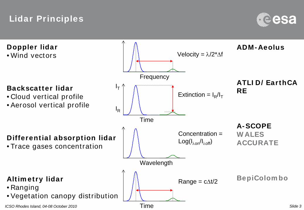
Lidar Principles
Velocity = /2*f
Frequency
Doppler lidar•Wind vectors
ADM-Aeolus
IT
IRTime
Extinction = IR /ITBackscatter lidar•Cloud vertical profile•Aerosol vertical profile
ATLID/EarthCA RE
Wavelength
Concentration = Log(Ion /Ioff )
Differential absorption lidar•Trace gases concentration
A-SCOPEWALESACCURATE
Time
Range = ct/2Altimetry lidar•Ranging•Vegetation canopy distribution
BepiColombo

Slide 4ICSO Rhodes Island, 04-08 October 2010
Current ESA lidar missions under development
ADM-Aeolus - 2013 EarthCARE - 2013
BepiColombo - 2014
ICSO Rhodes Island, 04-08 October 2010 Slide 4

Slide 5ICSO Rhodes Island, 04-08 October 2010
Atmospheric Dynamics Mission-Aeolus
Scientific objective: quantify global measurements of vertical wind profiles in the troposphere and lower stratosphere to improve the quality of weather forecasts, and to advance our understanding of atmospheric dynamics and climate processes.
MISSION PARAMETERSOrbit:• Sun-synchronous• Altitude ~ 405 km• Local time ~18:00 ascending node
Mass: 1500 kgPower: 2.3 kW
Mission life: 3 yearsPAYLOAD
• Doppler Wind Lidar (ALADIN)
ICSO Rhodes Island, 04-08 October 2010 Slide 5

Slide 6ICSO Rhodes Island, 04-08 October 2010
Atmospheric Dynamics Mission-Aeolus
Main Observation requirements
PBL Tropo- sphere
Strato- sphere
Vertical Domain [km] 0-2 2–16 16-30
Vertical Resolution
[km] 0.5 1 2–5
Horizontal Domain Global
Profile Separation [km] 200
Accuracy HLOS [ms-1] 2 2–3 3–5
Dynamic Range [ms-1] ± 150
Horizontal integration
[km] 50
Measurement geometry

Slide 7ICSO Rhodes Island, 04-08 October 2010
Atmospheric Dynamics Mission-Aeolus
Measurement principleMie, Fringe imaging receiver Rayleigh, Double edge receiver
ICSO Rhodes Island, 04-08 October 2010

Slide 8ICSO Rhodes Island, 04-08 October 2010
Atmospheric Dynamics Mission-Aeolus
Instrument features
Transmitter (Nd:YAG)WavelengthPulse energyRepetition rateLine widthDuty cycle
355
nm120
mJ100
Hz30
MHz42 %
Transmit-receive TelescopeTelescope diameterTelescope transm. (incl. obscuration)Transmitter beam divervence (full angle)Receiver Field-of-View (full angle)
1.5 m> 80 %12 µrad19 µrad
ReceiverFizeau interferometer (Mie)
Free Spectral RangeUseful Spectral RangeFringe width (FWHM)
Double Fabry-Perot (Rayleigh)Free Spectral RangeSpacin
Detector quantum efficiency
2.2 GHz1.5 GHz145
MHz
10.9
GHz5.5
GHz> 80%
Laser diode stack used to pump the master oscillator and the power amplifiers of the transmitter.
The completed Aeolus 1.5 m transmit/receive SiC telescope
The Flight Model of the Mie Spectrometer with the Fizeau etalon and the associated optics
Detection Front-end Unit with the Accumulation CCD

Slide 9ICSO Rhodes Island, 04-08 October 2010
Atmospheric Dynamics Mission-Aeolus
Status •Platform Integration completed and in storage
•Laser: testing in progress, some design issues still need to be resolved (alignment stability)
•Low pressure Oxygen environment to the majority of the high intensity laser optics.
•Operation in continuous mode
Power Laser HeadICSO Rhodes Island, 04-08 October 2010

Slide 10ICSO Rhodes Island, 04-08 October 2010
ADM-Aeolus: Airborne Campaigns
Campaigns activities First results from 3rd airborne campaignGround return compares good to DEMFirst Rayleigh winds compare qualitatively good to 2 µm wind lidar
Reference 2 m LOS wind
A2D Rayleigh LOS wind
http://www.pa.op.dlr.de/aeolus/ICSO Rhodes Island, 04-08 October 2010 Slide 10

Slide 11ICSO Rhodes Island, 04-08 October 2010
EarthCARE: Earth Clouds Aerosols and Radiation Explorer Mission
Scientific objective: quantify aerosol-cloud-radiation interactions so to include them correctly in climate and numerical weather forecasting models.
MISSION PARAMETERSOrbit:• Sun-synchronous• Altitude : 393 km• Local time : 13:45..14:00 descending node
Mass: 2000 kgPower: 1.5 kW
Mission life: 3 years
PAYLOAD
• Backscatter Lidar (ATLID)
• Cloud Profiling Radar (CPR)
• Multi-Spectral Imager (MSI)
• Broad-Band Radiometer (BBR)
Instantaneous radiative flux with an TOA error of 10 Wm-2
ICSO Rhodes Island, 04-08 October 2010 Slide 11

Slide 12ICSO Rhodes Island, 04-08 October 2010
EarthCARE: ATmospheric backscatter LIDar
Main Observation requirements
Measurement geometry
20 km
40 km
Sampling = 100 m
0 km
Sampling = 500 m
Averaging length = 10 km
Horizontal sampling distance =100 m
Laser pulse
Atmosphere
Signal
Time
Mie co- polar
channel
Rayleighchannel
Mie X- polar
channel
Cirrus
Cirrus optical depth
0.05
Backscatter sr-1 m -1
8 x 10 -7 2.6 x 10 -5
Vertical resolution 100 m 300 m 100 m
Required accuracy @ 10 km integration
50 % 15 % 45 %
Instrument sized to detect the weak signal from the thinnest radiatively significant cirrus cloud in daytime above dense cloud deck
Slide 12

Slide 13ICSO Rhodes Island, 04-08 October 2010
EarthCARE: ATmospheric backscatter LIDar
-6 -4 -2 0 2 4 6Relative frequency (GHz)
arbitra
ry u
nit
-6 -4 -2 0 2 4 6Relative frequency (GHz)
arbitra
ry u
nit
-6 -4 -2 0 2 4 6Relative frequency (GHz)
arbitra
ry u
nit
Rayleigh scattering contribution
Mie scattering contribution
HSR filter transmission
UV (355 nm) Backscatter Lidar with High Spectral Resolution Receiver to separate Rayleigh (molecular) and Mie (cloud,aerosol) cross and co- polarisation return
Measurement principle

Slide 14ICSO Rhodes Island, 04-08 October 2010
EarthCARE: ATmospheric backscatter LIDar
Instrument requirements
Parameters Value
TransmitterWavelengthPulse energyRepetition rateLine width
355
nm30
mJ74
Hz50
MHz
Receive TelescopeTelescope diameter 0.6 m
ReceiverHSR
Etalon Working ApertureAcceptance angleOverall finessePeak transmission BandwidthFree spectral range
Background filter rejectionWorking AperturePeak transmissionOverall finesseBandwidthFree spectral range
20 mm0.78 mrad8> 87 %< 0.3 pm2.4 pm
38 mm> 80 %3712 pm0.45 nm
Capacitance stabilised HSR etalon have been developed and successfully assessed against environment loads.

Slide 15ICSO Rhodes Island, 04-08 October 2010
EarthCARE: ATmospheric backscatter LIDar
Status:Preliminary Design Review completedBi-static configurationPressurised laser

Slide 16ICSO Rhodes Island, 04-08 October 2010
EarthCARE: ATLID pre-development
ATLID Laser Source: Medium energy frequency tripled and stabilised Nd:YAG laser MO/PA architecture
Oscillator: End pump; 8 mJ, 15 % o-oAmplifier based on patented Innoslab® concept:Slab crystal partially end-pumped from 2 sidesSignal folded in single pass configuration with constant fluence: scalable output85 mJ with 21 % o-oHarmonic section: LBO crystals: efficiency < 50 %
Parameters Performance
Output energy 34 mJ
Optical–optical efficiency 8% [808 nm-355 nm]
PRF 100 Hz
Spatial quality M2
< 1.7
Boresight stability < ±41 µrad
ptp
over 10 min
Pulse duration < 35ns
Longitudinal mode Single
Pulse linewidth < 50MHz
Spectral purity 99% in 100MHz
Frequency stability < 10MHz rms
over 1.4 sec

Slide 17ICSO Rhodes Island, 04-08 October 2010
EarthCARE: ATLID pre-development
ATLID Stacks: laser diodes manufacturers involved in the development of a stack optimised for a space application: long lifetime, high efficiency
Parameters Requirements
Wavelength (807 +
2) nm
Spectral width 2-3 nm
Peak output power > 700 W
Pulse width 150-200 µs
Repetition rate 70-100 Hz
Total efficiency > 50%
Emitting area < 10 x 14 mm
Divergence < 10 x 60 deg
Polarisation Linear >95%
Lifetime 10 billion shots
Highly-Reliable Laser Diodes and Modules for Spaceborne Applications, E. Deichsel, Jenoptik, Session 4a

Slide 18ICSO Rhodes Island, 04-08 October 2010
A-SCOPE: Advanced-Space Carbon and Climate Observation of Planet Earth Mission
Scientific objective: : The observation of the spatial and temporal gradients of atmospheric XCO2 with a precision and accuracy sufficient to constrain CO2 fluxes within 0.02 Pg C yr-1 on a scale of 1000 x 1000 km2.
MISSION PARAMETERS
Orbit:• Sun-synchronous• Altitude ~ 400 km• Local time 06:00descending node
Mass: ~ 1000 kgPower: ~ 1.7 kW
Mission life: 3 years
PAYLOAD
• Integrated Path Differential Absorption lidar (IPDA)
ICSO Rhodes Island, 04-08 October 2010 Slide 18

Slide 19ICSO Rhodes Island, 04-08 October 2010
A-SCOPE: Advanced-Space Carbon and Climate Observation of Planet Earth Mission
NIR (1.57 or 2.05 m) DIAL lidar for total column dry air CO2 mixing ratio
Value
Geophysical product XCO2
Random error [ppm] 0.5
Systematic error [ppm] 0.05
Coverage Global
Horizontal Resolution observation
[km] 50
Horizontal Resolution measurement
[m] 100
Vertical resolution Total column
Main Observation requirements
10 20 30Altitude [km]
Wei
ghting f
unct
ion [
-] 1.0
0.8
0.6
0.4
0.2
= 2.05 m
= 1.57 m

Slide 20ICSO Rhodes Island, 04-08 October 2010
A-SCOPE: Advanced-Space Carbon and Climate Observation of Planet Earth Mission
Instrument parametersInstrument design drivers:•Low random error:0.5 ppm wrt 380 ppm (0.13 % of DAOD) for ~ 350 measurements
– high laser power ×
telescope aperture– low detector noise– maximize the on and off-lines pulses overlap on ground
• Very low systematic error: 10 % of random error for 1000 x 1000 km2
– laser spectral stability and knowledge– laser spectral purity– stability of power monitoring of emitted laser pulses– stability and knowledge of the S/C pointing
Parameters 1.57 m 2.05 m
TransmitterPulse energyRepetition rateFrequency accuracyLinewidthSpectral purity
50 mJ50 Hz70 kHz50 MHz>99.95
55
mJ50
Hz100 kHz< 50 MHz> 99.93 %
Receive TelescopeTelescope diameterFOV
1 m0.47 mrad
1.2 m0.220 mrad
DetectorQENEP
0.7446 fW/Hz0.5
0.75100 fW/Hz 0.5

Slide 21ICSO Rhodes Island, 04-08 October 2010
A-SCOPE: pre-development
Parameters Requirements
OPO-OPA Fiber laser
Spectral band (um) 1.57 2.05 2.05
PRF (Hz) 50 30 2000-4000
Power (W) 2.5 1.2 2.5
Energy per pulse (mJ) 50 40 1.5
Bandwidth (MHz) 60 60 60
Spectral Stability (MHz) over 10 s 0.07 1.5 1.5
Spectral purity in 1 GHz 99.94% 99.98% 99.9%
A-SCOPE laser sources:
OPO-OPA at 1.57 m
OPO-OPA at 2.05 mFibre laser at 2.05 m

Slide 22ICSO Rhodes Island, 04-08 October 2010 Multiplication1 2 3 4 5 6 7
Exc
ess
Noi
se F
acto
r
0.8
1.0
1.2
1.4
1.6
1.8
2.0
Exc
ess
Nois
e fa
ctor
Reverse Voltage(V)0 10 20 30 40 50 60 70
Cur
rent
(A)
10-13
10-12
10-11
10-10
10-9
10-8
10-7
10-6
10-5
Mul
tiplic
atio
n
5
10
15
20
25
30
Dark currentPhotocurrentMultiplicationT=200K
=2.1m
IV characteristics of Type-II APD
A-SCOPE: pre-development
Parameters
QE 70%
Active area diameter 150 m
Excess noise 1.5
NEP 100 fW/Hz0.5]
Bandwidth 20 MHz
Gain stability 0.1 % rms (short term)
Linearity 5 % rms
A-SCOPE APD detectors at 2.05 m
HgCdTe:APD based on loophole junctions Amplifier based on CMOS TIAMCT hybridised directly ontothe silicon chip
InAlAs:Type-II superlattice heterojunctionSAM structureMBE growth
InAs:InAs MBE and MOVPE growthSAM structure

Slide 23ICSO Rhodes Island, 04-08 October 2010
Earth Explorer 8
Opportunity Mission
• Release of the Call 02.10.09• Proposals 01.06.10
• 100 M€ industrial cost for the space segment and mission specific ground segment
• a minimum TRL of 4-5 required by the end of Phase A
• 31 proposals received7 proposals based on lidar technique
• Results of evaluation expectedin NOV 2010
Slide 24ICSO Rhodes Island, 04-08 October 2010
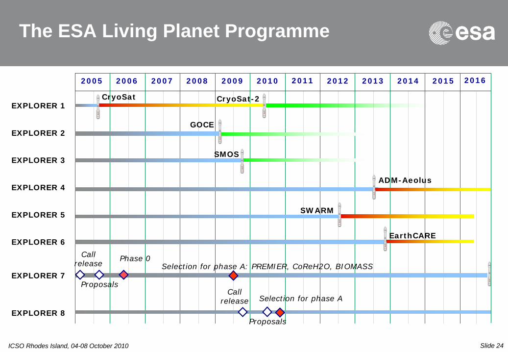
The ESA Living Planet Programme
CryoSat-2EXPLORER 1
EXPLORER 2
EXPLORER 4
EXPLORER 3
EXPLORER 5
EXPLORER 6
GOCE
SMOS
ADM-Aeolus
SWARM
EarthCARE
Call release
Proposals
Selection for phase A: PREMIER, CoReH2O, BIOMASS
CryoSat
Phase 0
EXPLORER 7
Call release Selection for phase A
2005 2006 20122007 2008 2009 2010 2011 2013 2014 2015 2016
EXPLORER 8Proposals

Slide 25ICSO Rhodes Island, 04-08 October 2010
Thank you for your attention
Merci de votre attention
Bedankt voor
jullie
andacht
Danke für
Ihre
Aufmerksamkei
Gracias por su
atención
Grazie per la vostra attenzione
σας ευχαριστώ!