esc series motors enhanced performance cast iron units
TRANSCRIPT
e n e r t e c h m o t o r s . c o m . a u
Three phase asynchronousESC Series Motors Enhanced performance cast iron units
2 e n e r t e c h m o t o r s . c o m . a u
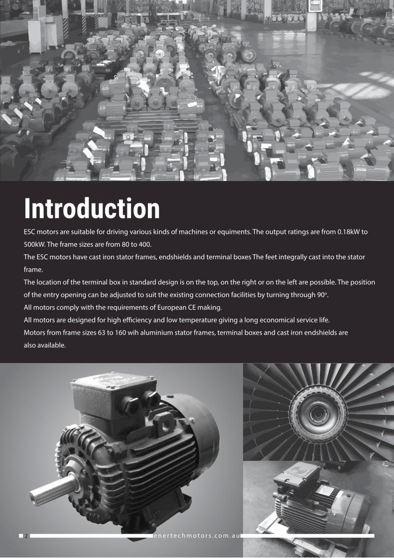
ESC motors are suitable for driving various kinds of machines or equiments. The output ratings are from 0.18kW to
500kW. The frame sizes are from 80 to 400.
The ESC motors have cast iron stator frames, endshields and terminal boxes The feet integrally cast into the stator
frame.
The location of the terminal box in standard design is on the top, on the right or on the left are possible. The position
of the entry opening can be adjusted to suit the existing connection facilities by turning through 90o.
All motors comply with the requirements of European CE making.
All motors are designed for high e�ciency and low temperature giving a long economical service life.
Motors from frame sizes 63 to 160 wih aluminium stator frames, terminal boxes and cast iron endshields are
also available.

e n e r t e c h m o t o r s . c o m . a u 3
Cooling and ventilationThe standard cooling method is totally Enclosed fan-cooled
(TEFC) in accordance with code IC411 of I EC 60034-6. Standard
motors in sizes 80-315 are equipped with radial-�ow plastic
fans. Standard motors in size 355 are equipped with radial-�ow
aluminium fans.
EnclosureThe standard degree of protection is IP55. The
IP55 enclosure means complete hoseproof and
dustproof protection. A higherdegree of
protection is available.
Voltage and frequencyStandard voltages are 380V/50Hz or 415V/50Hz, but can be
wound for any single voltage in the range 200-600V at a
frequency 50 or 60 Hz. The motors will operate satisfactorily
with voltage variations of ±10% from the rated voltage.
ConnectionDirect - on line starting can be used on all frame
sizes. Motors up to and including 3kW are star
connected and cannot be started with
Star/Delt started. Motors 4kW and above can
be started with Star/Delt started.
NoiseThe permitted noise levels of electrical machines are �xed in
IEC60034 - 9 (EN60034-9). The noise level of ESC motors is well
below these limit value. Fordetails, please referto the perfor-
mance data tables.
Quality assuranceStringent quality procedures are observed from �rst design to �nished products in accordance with IS09001 document-
ed quality systems. Our factories have been assessed to meet these requirements, a further assurance that only the
highest possible standards of quality are accepted.
VibrationStandard motors are designed for vibration
class N (normal). Vibration class R (reduced) and
vibration class S (special) are available on
request.

60034-30
4 e n e r t e c h m o t o r s . c o m . a u
ESC motors are built to comply with the requirements of the following international standards and regulation:
1. International Electrotechnical commission - IEC 60034 and I EC 60072.
2. British Standards - BS5000 and BS 4999.
3. Australian Standards -AS 1359.
4. The requirements of European EC marking. Low voltage Directive 73/23 (1973), modi�ed by Directive 93/68 (1993) and
the EMC - Directive 89/336. These ESC motors are designed to use with other machinery, and they should only be used if
the complete machinery is in conformity with the provisions of the Directive of safety of machinery (89/93/EEC).
5. CEMEP agreement-all motors with standard rating include in this catalogue comply with e�ciency class IE1 and bear the
corresponding label on the rating plate. For e�ciency data at 50%, 75% and full load, please refer to the performance data
tables. Motors comply with e�ciency class IE2 are available on request.

5e n e r t e c h m o t o r s . c o m . a u
Against solar radiationHigh solar radiation will result in undue
temperature rise. In these circumstances motors
should be screened from solar radiation by
placement of adequate sunshades which do not
inhibit air �ow.
IP standards explanation
First numeral
Second numeral
First characteristic numeral Degree of protection of persons against approach to live parts or contact with live or moving
parts (other than smooth rotating shafts and the like) inside the enclosure, and degree of protection of equipment
within the enclosure against the ingress of solid foreign bodies.
4. Protected against solid object greater than 1.0 mm: Wires or strips of thickness greater than 1.0 mm, solid objects
exceeding 1.0 mm.
5. Dust protected: Ingress of dust is not totally prevented but it does not enter in su�cient quantity to interfere with
satisfactory operation of the equipment.
6. Dust tight: No ingress of dust.
International protection rating
pre�x (IEC 60034 - 5)
Second characteristic numeral
4. Protected against splashing water: Water splashed against the enclosure from any direction shall have no harmful
e�ect.
5. Protected against water jets: Water projected by a nozzle against the enclosure from any direction shall have no
harmful e�ect.
6. Protected against heavy seas: Water from heavy seas or water projected in powerful jets (larger nozzle and higher
pressure than second numeral 5) shall not enter the enclosure in harmful quantities.
Degree of protectionStandard levels of enclosure protection for all ESC frame sizes for
both motor and terminal box is IP55, with IP56, IP65 and IP66
available on request. Enclosure designations comply with IEC or
AS60529. The enclosure protection required will depend upon the
environmental and operational conditions within which the motor
is to operate.
I P 5 5
1 2
6 e n e r t e c h m o t o r s . c o m . a u

Shaft ESC motors have standard shaft extension lengths which provided with standard key, drilled and tapped hole. Non
standard shaft extensions are available upon special order, with shaft design outlined on a detailed drawing. Shaft exten-
sion run out, concentricity and perpendicularity to face of standard �ange mount motors, comply with normal grade
tolerance as speci�ed in IEC 60072-1 and AS1359. Precision grade tolerance is available upon special order.
Finish Standard ESC motor color is RAL 5008. Other colors are also available. All castings and steel parts are provided with a
prime coat of rust-resistant paint. The �nishing coat of enamel paint is su�cient for normal conditions, however special
paint systems can be provided to accommodate stringent requirements for motors in corrosive environments. Special
coatings are needed to resist such substances as acid, salt water and extreme climatic conditions.
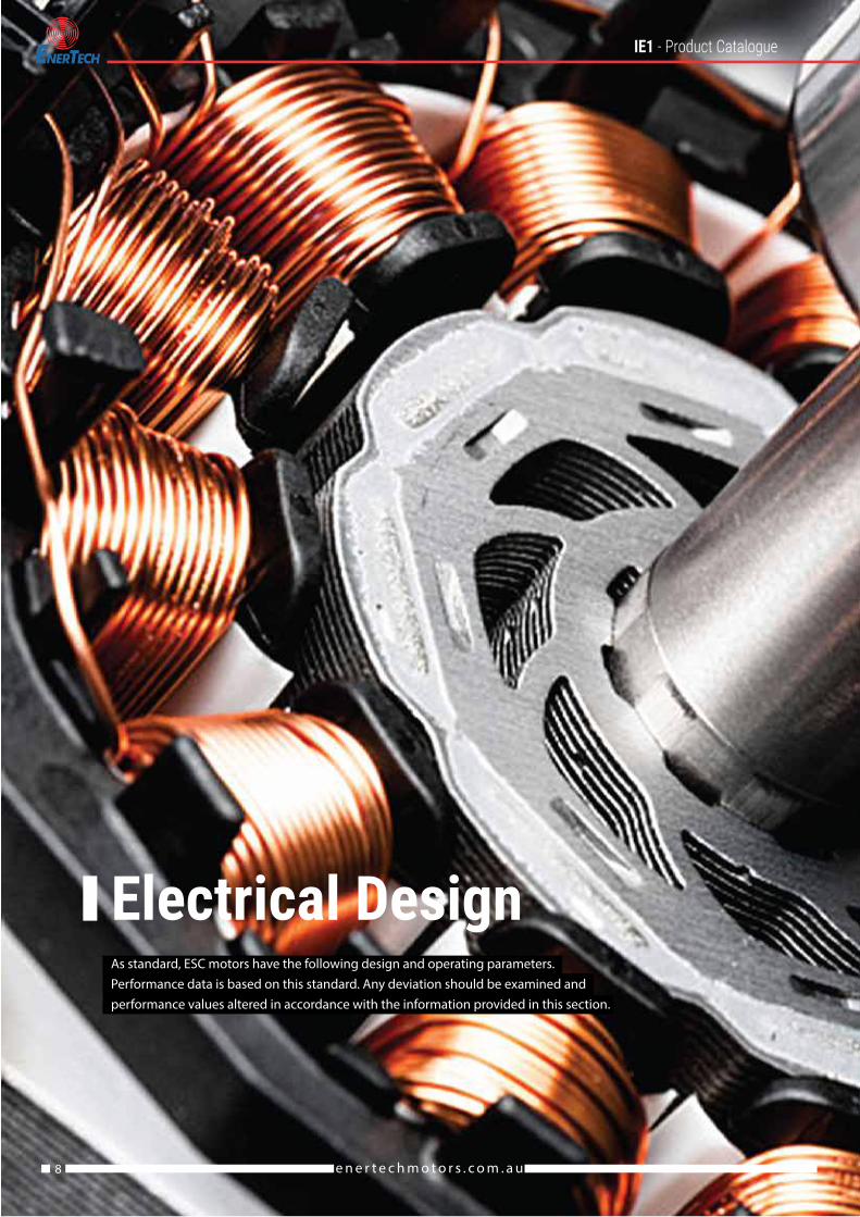
Electrical design As standard, ESC motors have the following design and operating parameters. Performance data is based on this standard. Any
deviation should be examined and performance values altered in accordance with the information provided in this section.
Three phase, 380V, 50Hz
Ambient cooling air temperature, 40°C
Altitude - 1000m Duty cycle 51 (continuous)
Rotatio - Clockwise viewed from drive end
Connection - 220 volt Delta/380 volt Star (3kW and below)
- 380 volt Delta/660 volt Star (4kW and above)
7e n e r t e c h m o t o r s . c o m . a u
e n e r t e c h m o t o r s . c o m . a u8
As standard, ESC motors have the following design and operating parameters.Performance data is based on this standard. Any deviation should be examined andperformance values altered in accordance with the information provided in this section.
X
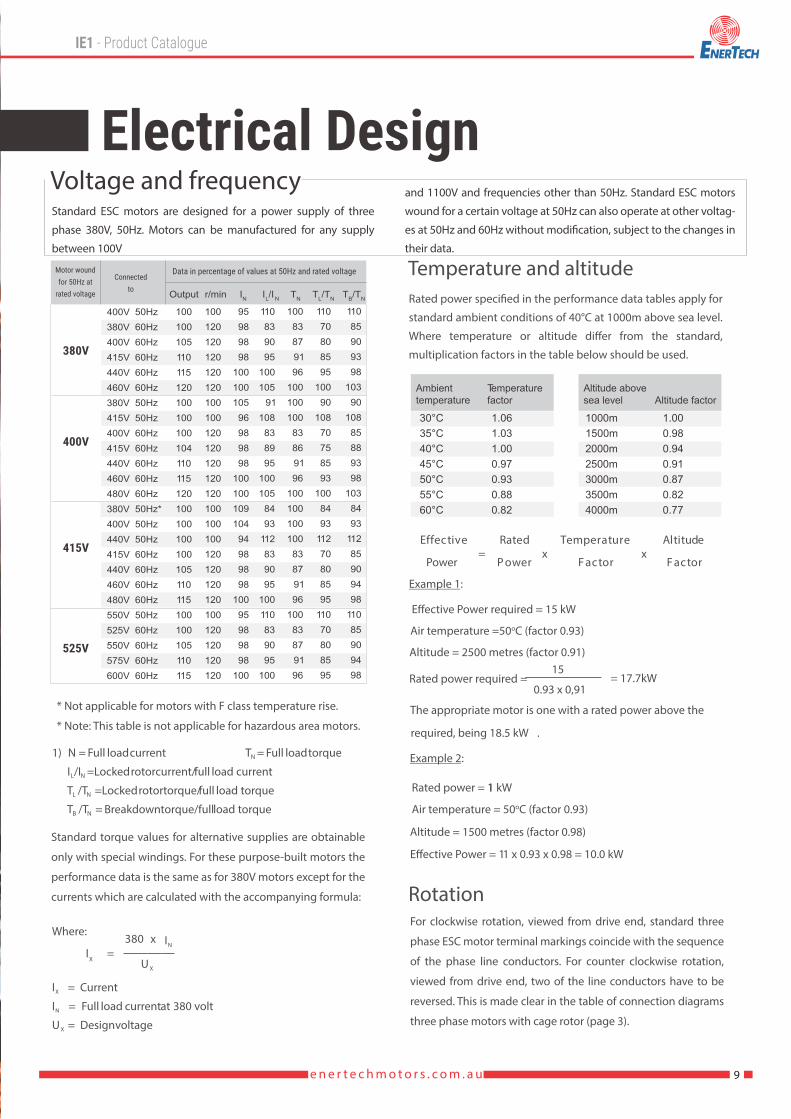
Voltage and frequency and 1100V and frequencies other than 50Hz. Standard ESC motors
wound for a certain voltage at 50Hz can also operate at other voltag-
es at 50Hz and 60Hz without modi�cation, subject to the changes in
their data.
Standard ESC motors are designed for a power supply of three
phase 380V, 50Hz. Motors can be manufactured for any supply
between 100V
9e n e r t e c h m o t o r s . c o m . a u
Rated power speci�ed in the performance data tables apply for
standard ambient conditions of 40°C at 1000m above sea level.
Where temperature or altitude di�er from the standard,
multiplication factors in the table below should be used.
Temperature and altitude
1) N = Full load current T = Full load torqueN
I /I =Locked rotor current/ full load currentL N
T /T =Locked rotor torque/ full load torqueL N
T /T = Breakdown torque/full load torqueB N
Where:
I = Current X
I = Full load current at 380 voltN
U = Design voltage
I X
=380 x
U X
IN
Power=
P owerx
F actorx
Effective Rated Temperature Altitude
F actor
Example 1:
E�ective Power required = 15 kW
Air temperature =50oC (factor 0.93)
Altitude = 2500 metres (factor 0.91)
Rated power required = 15
0.93 x 0,91= 17.7kW
The appropriate motor is one with a rated power above the
required, being 18.5 kW .
Example 2:
Rated power = 11 kW
Air temperature = 50oC (factor 0.93)
E�ective Power = 11 x 0.93 x 0.98 = 10.0 kW
Altitude = 1500 metres (factor 0.98)
* Not applicable for motors with F class temperature rise.
* Note: This table is not applicable for hazardous area motors.
Standard torque values for alternative supplies are obtainable
only with special windings. For these purpose-built motors the
performance data is the same as for 380V motors except for the
currents which are calculated with the accompanying formula:
For clockwise rotation, viewed from drive end, standard three
phase ESC motor terminal markings coincide with the sequence
of the phase line conductors. For counter clockwise rotation,
viewed from drive end, two of the line conductors have to be
reversed. This is made clear in the table of connection diagrams
three phase motors with cage rotor (page 3).
Rotation
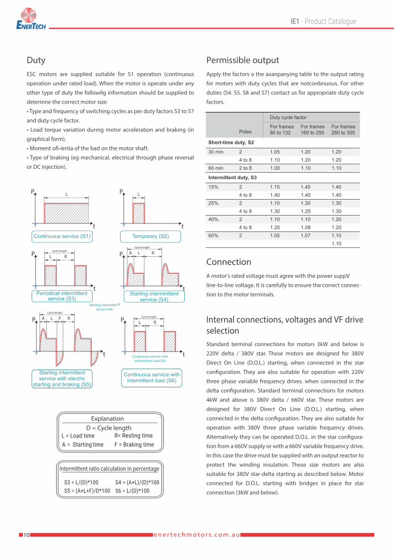
Explanation
Intermittent ratio calculation in percentage
D = Cycle length
10 e n e r t e c h m o t o r s . c o m . a u
ESC motors are supplied suitable for S1 operation (continuous
operation under rated load). When the motor is operate under any
other type of duty the followilg information should be supplied to
deterinne the correct motor size:
• Type and frequency of switching cycles as per duty factors S3 to 57
and duty cycle factor.
• Load torque variation during motor acceleration and braking (in
graphical form).
• Moment ofi-iertia of the bad on the motor shaft.
• Type of braking (eg mechanical. electrical through phase reversal
or DC injection).
DutyApply the factors o the axanpanying table to the output rating
for motors with duty cycles that are notconbnuous. For other
duties (S4. S5. S8 and S7) contact us for appropriate duty cycle
factors.
Permissible output
A motor's rated voltage must agree with the power suppV
line-to-line voltage. It is carefully to ensure the correct connec-
tion to the motor terminals.
Connection
Standard terminal connections for motors 3kW and below is
220V delta / 380V star. These motors are designed for 380V
Direct On Line (D.O.L.) starting, when connected in the star
con�guration. They are also suitable for operation with 220V
three phase variable frequency drives. when connected in the
delta con�guration. Standard terminal connections for motors
4kW and above is 380V delta / 660V star. These motors are
designed for 380V Direct On Line (D.O.L.) starting, when
connected in the delta con�guration. They are also suitable for
operation with 380V three phase variable frequency drives.
Alternatively they can be operated D.O.L. in the star con�gura-
tion from a 660V supply or with a 660V variable frequency drive.
In this case the drive must be supplied with an output reactor to
protect the winding insulation. These size motors are also
suitable for 380V star-delta starting as described below. Motor
connected for D.O.L. starting with bridges in place for star
connection (3kW and below).
Internal connections, voltages and VF driveselection

11e n e r t e c h m o t o r s . c o m . a u
All of the following starter options are available and are the best
supplied together with the motor.
Starting
When an electric motor is started by direct connection to the
power supply (D.O.L.), it draws a high current, called the
'starting current, which is approximately equal in magnitude to
the locked rotor current IL. As listed in the performance data,
locked rotor current can be up to 8 times the rated current IN of
the motor. In circumstances where the motor starts under no
load or where high starting torque is not required, it is preferble
to reduce the starting current by one of the following means.
D.O.L Starters
The ESC motors 4kW and above are suitable for the star-delta
starting method. Through the use of a star-delta starter, the
motor terminals are connected in the star con�guration during
starting, and reconnected to the delta con�guration when
running. The bene�ts of this starting method are a signi�cantly
lower starting current, to a value about 1/3 of the D.O.L.
starting current, and a corresponding starting torque also
reduced to about 1/3 of its D.O.L. value. It should be noted that
a second current surge occurs on changeover to the delta
connection. The level of this surge will depend on the speed
the motor has reached at the moment of change over.
Star - Delta starting
Variable Voltage Variable Frequency drives are primarily recog-
nized for their ability to manipulate power from a constant 3
phase 50/60Hz supply converting it to variable voltage and
variable frequency power. This enables the speed of the motor
to be matched to its load in a �exible and energy e�cient
manner. The only way of producing starting torque equal to full
load torque with kill load current is by using VVVF drives. The
functionally �exible VVVF drive is also commonly used to
reduce energy consumption on fans, pumps and compressors
and o�ers a simple andrepeatable method of changing speeds
or �ow rates.
VVVF Drives
Capacitive voltages in the rotor can be generated due to an
e�ect caused by harmonics in the waveform causing voltage
discharge to earth through the beatings. This discharge results
in etching of the bearing running surfaces. This e�ect is known
as Electrical Discharge Machining (EDM). It can be control with
the �tment of appropriate �lters to the drive. To futher reduce
the of EDM, an insulated non drive bearing can be used. ESC
recommends the use of insulated bearings for all motors 315
frame and above.
EDM Concerns
12 e n e r t e c h m o t o r s . c o m . a u
Where:
n = full load speed N
n = asynchronous speed S
P/P = partial load factorN
Current at partial loadsCurrent at partial loads can be calculated using the following formula:
Where:I = partial load current (amps)X
Pout = partial load (kW)X
U = rated voltage N
cos φ = partial load power factorX
η = partial load e�ciency (%)X
Torque characteristics Typical characteristics of torque behaviour relative to speed are shown in the torque speed curve example below.
Where: T = full load torque N
T = locked rotor torque L
T = pull-up torque U
T = break down torque B
n = full load speedN
n = asynchronous speedS
ESC motors all exceed the minimum starting torque requirements for Design N (Normal torque) as speci�ed in IEC60034-12, and in most cases meet the requirements of Design H (High torque). Rated torque can be calculated with the following formula:
Where: T = full load torque (Nm) N
P = full load output power (kW) N
n = full load speed (r/min) N
I =xPoutx 5x 10
3 x U X cosφ X ηN X X
pN
T =N
9950 x
nN
Load Torque
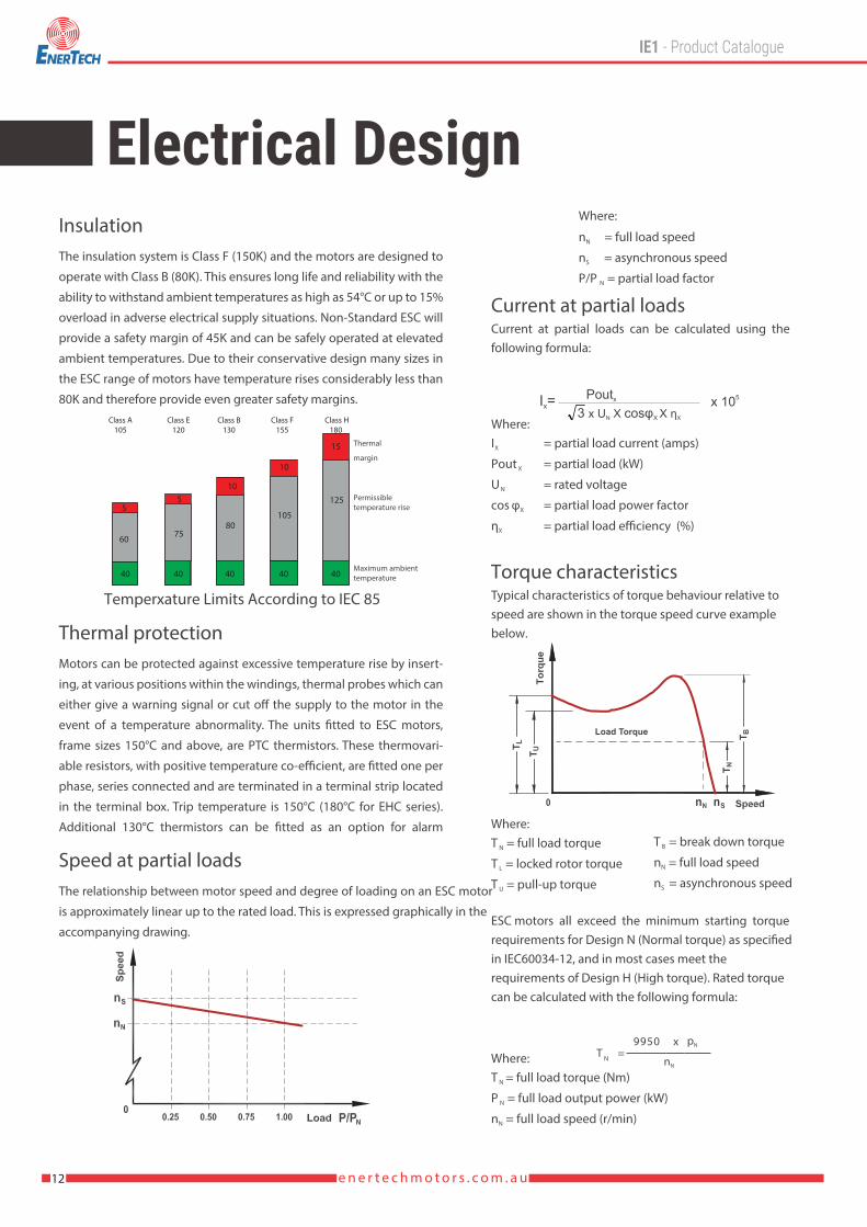
The insulation system is Class F (150K) and the motors are designed to
operate with Class B (80K). This ensures long life and reliability with the
ability to withstand ambient temperatures as high as 54°C or up to 15%
overload in adverse electrical supply situations. Non-Standard ESC will
provide a safety margin of 45K and can be safely operated at elevated
ambient temperatures. Due to their conservative design many sizes in
the ESC range of motors have temperature rises considerably less than
80K and therefore provide even greater safety margins.
Insulation
Motors can be protected against excessive temperature rise by insert-
ing, at various positions within the windings, thermal probes which can
either give a warning signal or cut o� the supply to the motor in the
event of a temperature abnormality. The units �tted to ESC motors,
frame sizes 150°C and above, are PTC thermistors. These thermovari-
able resistors, with positive temperature co-e�cient, are �tted one per
phase, series connected and are terminated in a terminal strip located
in the terminal box. Trip temperature is 150°C (180°C for EHC series).
Additional 130°C thermistors can be �tted as an option for alarm
Thermal protection
The relationship between motor speed and degree of loading on an ESC motor
is approximately linear up to the rated load. This is expressed graphically in the
accompanying drawing.
Speed at partial loads
Thermal
margin
Permissibletemperature rise
Maximum ambienttemperature
Temperxature Limits According to IEC 85
40 40 40 40 40
60
55
10
10
15
7580
105
125
Class A105
Class E120
Class B130
Class F155
Class H180

13e n e r t e c h m o t o r s . c o m . a u
14 e n e r t e c h m o t o r s . c o m . a u
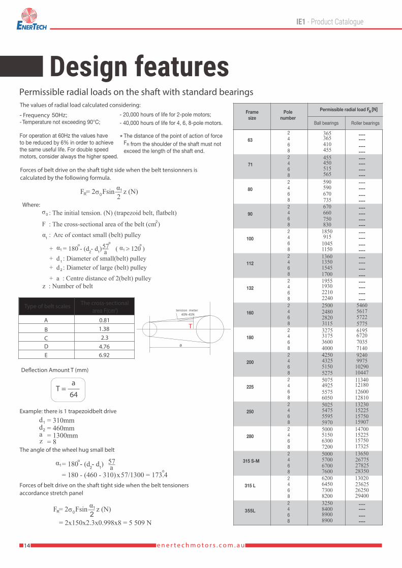
The values of radial load calculated considering:
Permissible radial loads on the shaft with standard bearings
355L
------------------------------------------------------------------------------------
------------
365365410455455450515565590590670735670660750830
1850915
1045115013601350154517001955193022102240250024802820311532753175360040004250432551505275507549255575605050255475559559705000515063007200500057006700760062006450730082003250840089008900
13020236252625029400
13650267752782528350
14700152251575017325
13230152251575015907
11340121801260012810
92409975
1029010447
6195672070357140
5460561757225775
*
Forces of belt drive on the shaft tight side when the belt tensionners iscalculated by the following formula.
ασF = 2 Fsin z (N)R 01
2
σ0
F
: The initial tension. (N) (trapezoid belt, flatbelt)
: The cross-sectional area of the belt (cm )2
: Arc of contact small (belt) pulley
α1+ = 180 - (d - d )12
o 57o
a >( 120 )α1o
+ d : Diameter of small(belt) pulley
α1
+ d : Diameter of large (belt) pulley2
+ a : Centre distance of 2(belt) pulley z : Number of belt
2
A
BCDE
0.811.382.3
4.766.92
De�ection Amount T (mm)
T =a
64
Type of belt scales The cross-sectional
Example: there is 1 trapezoidbelt drive
1d2d
az
= 310mm= 460mm= 1300mm= 8
α1 = 180 - (d - d )12
o 57a o
= 180 - (460 - 310)x57/1300 = 173.4
The angle of the wheel hug small belt
Forces of belt drive on the shaft tight side when the belt tensioners accordance stretch panel
1
ασF = 2 Fsin z (N)R 01
2= 2x150x2.3x0.998x8 = 5 509 N
FrequencyT
Where:

15e n e r t e c h m o t o r s . c o m . a u
F
F
R
A
355L
max max
2000600070008000
1880300300
3690
Permissible axial loads on the shaft with standard bearings

16 e n e r t e c h m o t o r s . c o m . a u
17e n e r t e c h m o t o r s . c o m . a u
100 75 50
Efficiency %at % full loadFull load I , 50HzN
380V 400V 415V
Current
(A) (A) (A)
LockedrotorI /IL N
Momentof inertia
2J=1/4 GD2(kgxm )
Nosie level
at 1meterdB(A)
Netweight
(kg)
LockedrotorT /TL N
BreakdownT /TB N
TorqueFullloadTN
(Nm)
Output
(kW)
Fulllock
speed(rpm)
100 75 50
power factor, cos φat % full load
Frame Size
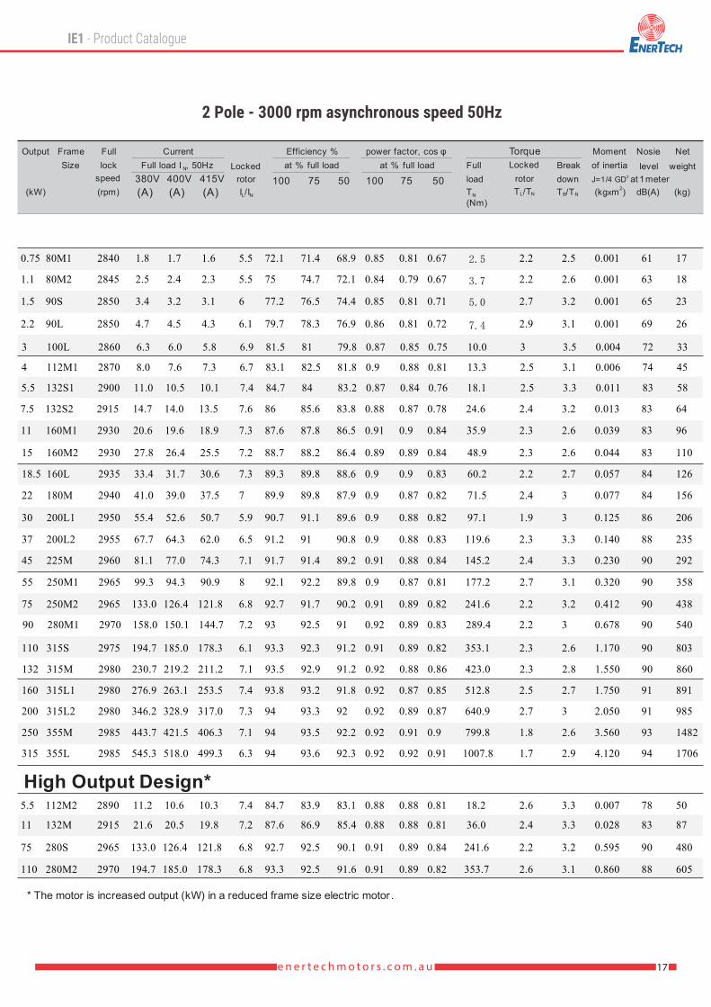
High Output Design*
* The motor is increased output (kW) in a reduced frame size electric motor .
0.75
1.1
1.5
2.2
3
4
5.5
5.5
7.5
11
11
15
18.5
22
30
37
45
55
75
75
90
110
110
132
160
200
250
315
2840 1.8 1.7 1.6 72.1 71.4 68.9 0.85 0.81 0.675.5 2.5 2.2 2.5 0.001 61 17
2845 2.5 2.4 2.3 75 74.7 72.1 0.84 0.79 0.675.5 3.7 2.2 2.6 0.001 63 18
2850 3.4 3.2 3.1 77.2 76.5 74.4 0.85 0.81 0.716 5.0 2.7 3.2 0.001 65 23
2850 4.7 4.5 4.3 79.7 78.3 76.9 0.86 0.81 0.726.1 7.4 2.9 3.1 0.001 69 26
2860 6.3 6.0 5.8 81.5 81 79.8 0.87 0.85 0.756.9 10.0 3 3.5 0.004 72 33
2870 8.0 7.6 7.3 83.1 82.5 81.8 0.9 0.88 0.816.7 13.3 2.5 3.1 0.006 74 45
2890 11.2 10.6 10.3 84.7 83.9 83.1 0.88 0.88 0.817.4 18.2 2.6 3.3 0.007 78 50
2900 11.0 10.5 10.1 84.7 84 83.2 0.87 0.84 0.767.4 18.1 2.5 3.3 0.011 83 58
2915 14.7 14.0 13.5 86 85.6 83.8 0.88 0.87 0.787.6 24.6 2.4 3.2 0.013 83 64
2915 21.6 20.5 19.8 87.6 86.9 85.4 0.88 0.88 0.817.2 36.0 2.4 3.3 0.028 83 87
2930 20.6 19.6 18.9 87.6 87.8 86.5 0.91 0.9 0.847.3 35.9 2.3 2.6 0.039 83 96
2930 27.8 26.4 25.5 88.7 88.2 86.4 0.89 0.89 0.847.2 48.9 2.3 2.6 0.044 83 110
2935 33.4 31.7 30.6 89.3 89.8 88.6 0.9 0.9 0.837.3 60.2 2.2 2.7 0.057 84 126
2940 41.0 39.0 37.5 89.9 89.8 87.9 0.9 0.87 0.827 71.5 2.4 3 0.077 84 156
2950 55.4 52.6 50.7 90.7 91.1 89.6 0.9 0.88 0.825.9 97.1 1.9 3 0.125 86 206
2955 67.7 64.3 62.0 91.2 91 90.8 0.9 0.88 0.836.5 119.6 2.3 3.3 0.140 88 235
2960 81.1 77.0 74.3 91.7 91.4 89.2 0.91 0.88 0.847.1 145.2 2.4 3.3 0.230 90 292
2965 99.3 94.3 90.9 92.1 92.2 89.8 0.9 0.87 0.818 177.2 2.7 3.1 0.320 90 358
2965 133.0 126.4 121.8 92.7 91.7 90.2 0.91 0.89 0.826.8 241.6 2.2 3.2 0.412 90 438
2965 133.0 126.4 121.8 92.7 92.5 90.1 0.91 0.89 0.846.8 241.6 2.2 3.2 0.595 90 480
2970 158.0 150.1 144.7 93 92.5 91 0.92 0.89 0.837.2 289.4 2.2 3 0.678 90 540
2970 194.7 185.0 178.3 93.3 92.5 91.6 0.91 0.89 0.826.8 353.7 2.6 3.1 0.860 88 605
2975 194.7 185.0 178.3 93.3 92.3 91.2 0.91 0.89 0.826.1 353.1 2.3 2.6 1.170 90 803
2980 230.7 219.2 211.2 93.5 92.9 91.2 0.92 0.88 0.867.1 423.0 2.3 2.8 1.550 90 860
2980 276.9 263.1 253.5 93.8 93.2 91.8 0.92 0.87 0.857.4 512.8 2.5 2.7 1.750 91 891
2980 346.2 328.9 317.0 94 93.3 92 0.92 0.89 0.877.3 640.9 2.7 3 2.050 91 985
2985 443.7 421.5 406.3 94 93.5 92.2 0.92 0.91 0.97.1 799.8 1.8 2.6 3.560 93 1482
2985 545.3 518.0 499.3 94 93.6 92.3 0.92 0.92 0.916.3 1007.8 1.7 2.9 4.120 94 1706
80M1
80M2
90S
90L
100L
112M1
112M2
132S1
132S2
132M
160M1
160M2
160L
180M
200L1
200L2
225M
250M1
250M2
280S
280M1
280M2
315S
315M
315L1
315L2
355M
355L

18 e n e r t e c h m o t o r s . c o m . a u
* The motor is increased output (kW) in a reduced frame size electric motor
.
100 75 50
Efficiency %at % full loadFull load I , 50HzN
380V 400V 415V
Current
(A) (A) (A)
LockedrotorI /IL N
Momentof inertia
2J=1/4 GD2(kgxm )
Nosie level
at 1meterdB(A)
Netweight
(kg)
LockedrotorT /TL N
BreakdownT /TB N
TorqueFullloadTN
(Nm)
Output
(kW)
Fulllock
speed(rpm)
100 75 50
power factor, cos φat % full load
Frame Size
High Output Design*
80M10.55 1410 1.5 1.4 1.4 71 70.5 68.9 0.75 0.67 0.554.6 3.7 2.4 2.7 0.002 54
80M20.75 1420 2.1 2.0 1.9 72.1 71.8 69.5 0.76 0.66 0.544.4 5.0 2.2 2.7 0.002 57
90S1.1 1410 2.8 2.7 2.6 75 74.6 73.2 0.79 0.68 0.554.3 7.5 2.2 3 0.002 61
90L1.5 1410 3.6 3.4 3.3 77.2 77 75.3 0.79 0.71 0.584.7 10.2 2.5 3 0.003 61
100L12.2 1415 5.1 4.8 4.7 79.7 78.9 77.4 0.81 0.73 0.595.3 14.8 2.5 2.9 0.007 61
100L23 1420 6.8 6.5 6.2 81.5 81.3 80.2 0.81 0.75 0.635.7 20.2 2.4 3 0.007 63
112M4 1440 8.7 8.3 8.0 83.1 82.8 81.7 0.83 0.77 0.695.7 26.5 2.7 3.1 0.010 67
132S5.5 1450 11.7 11.1 10.7 84.7 84.2 82.7 0.83 0.77 0.656.8 36.2 2.3 3.1 0.022 68
132M17.5 1450 15.0 14.3 13.7 86 85.6 83.7 0.86 0.82 0.727.2 49.4 2.6 3.1 0.030 68
132M211 1450 22.7 21.6 20.8 87.6 87.2 86.1 0.84 0.8 0.726.2 72.4 2.2 2.8 0.063 69
160M11 1460 22.4 21.3 20.5 87.6 87.8 85.1 0.84 0.82 0.766.8 72.0 2.3 2.8 0.075 70
160L15 1460 29.7 28.2 27.2 88.7 88.9 87.2 0.85 0.8 0.747.4 98.1 2.6 3.4 0.093 73
180M18.5 1465 35.5 33.7 32.5 89.3 88.7 86.8 0.88 0.83 0.737 120.6 2.1 3.2 0.140 75
180L22 1470 41.3 39.2 37.8 89.9 89.2 87.9 0.89 0.85 0.766.8 142.9 2.1 3 0.159 75
200L30 1475 55.5 52.7 50.8 90.7 89.6 88.2 0.89 0.87 0.816.5 194.2 2.2 3 0.265 80
225S37 1475 68.8 65.4 63.0 91.2 91.1 90 0.88 0.87 0.787 239.6 2.1 3.2 0.404 81
225M45 1475 82.8 78.7 75.8 91.7 91.2 89.5 0.89 0.86 0.86.6 291.4 2.2 2.8 0.470 82
250M155 1480 103.1 97.9 94.4 92.1 92 91 0.87 0.84 0.786.3 354.9 2.2 2.7 0.670 82
250M275 1480 136.0 129.2 124.5 92.7 92.6 91.9 0.89 0.87 0.836.3 484.0 2.2 3.2 0.880 82
280S75 1480 136.0 129.2 124.5 92.7 92.6 91.8 0.89 0.86 0.816.3 484.0 2.3 2.8 1.120 84
280M190 1485 163.0 154.9 149.3 93 92.7 91.8 0.89 0.86 0.817.1 578.8 2.6 3 1.460 84
280M2110 1480 200.8 190.8 183.9 93.3 93.1 92.5 0.89 0.86 0.816.2 709.8 2.4 2.8 2.680 85
315S110 1485 198.5 188.6 181.8 93.3 93 92.4 0.89 0.86 0.815.8 707.4 2.1 2.8 3.100 88
315M132 1485 236.9 225.1 216.9 93.5 93.2 92.5 0.89 0.87 0.826.3 848.9 2.2 2.6 3.300 88
315L1160 1490 286.6 272.3 262.4 93.8 93.5 92.8 0.89 0.86 0.825.7 1025.5 2 2.6 3.790 87
315L2200 1490 356.7 338.9 326.6 94 93.9 93 0.89 0.86 0.826.2 1281.9 2.3 2.7 4.500 89
355M250 1490 443.3 421.1 405.9 94 93.8 93.2 0.9 0.89 0.866.5 1602.3 2.1 3.1 5.670 90
355L315 1490 558.6 530.7 511.5 94 93.8 93.3 0.9 0.89 0.886 2019.0 2.1 3.3 6.660 90
17
18
22
26
33
37
46
60
73
88
105
125
153
170
221
283
340
375
455
506
590
670
842
908
992
1122
1490
1650

19e n e r t e c h m o t o r s . c o m . a u
.
* The motor is increased output (kW) in a reduced frame size electric motor
100 75 50
Efficiency %at % full loadFull load I , 50HzN
380V 400V 415V
Current
(A) (A) (A)
LockedrotorI /IL N
Momentof inertia
2J=1/4 GD2(kgxm )
Nosie level
at 1meterdB(A)
Netweight
(kg)
LockedrotorT /TL N
BreakdownT /TB N
TorqueFullloadTN
(Nm)
Output
(kW)
Fulllock
speed(rpm)
100 75 50
power factor, cos φat % full load
Frame Size
High Output Design*
80M10.37 915 1.2 1.1 1.1 62 61.4 55.5 0.71 0.63 0.523.2 3.9 1.8 2 0.002 46 17
80M20.55 915 1.7 1.6 1.6 65 64.7 63.2 0.72 0.62 0.523.3 5.7 2 2.2 0.003 50 20
90S0.75 920 2.2 2.1 2.0 70 68.7 65.6 0.71 0.74 0.543.6 7.8 2.3 2.6 0.003 53 23
90L1.1 925 3.1 2.9 2.8 72.9 71.6 69.5 0.73 0.65 0.523.5 11.4 2.1 2.5 0.004 59 26
100L1.5 925 4.0 3.8 3.7 75.2 74.8 72.4 0.75 0.66 0.544.3 15.5 2.3 2.9 0.007 62 32
112M2.2 935 5.6 5.3 5.1 77.7 77.2 75.9 0.76 0.74 0.64.4 22.5 2.2 2.5 0.014 65 41
132S3 960 7.4 7.0 6.8 79.7 79.4 78.5 0.76 0.7 0.575.8 29.8 2.1 3 0.029 66 59
132M14 960 9.8 9.3 9.0 81.4 83.9 82.4 0.76 0.7 0.576.4 39.8 2.1 2.7 0.036 66 68
132M25.5 960 12.9 12.3 11.8 83.1 82.6 81.5 0.77 0.74 0.586.5 54.7 2 2.5 0.045 67 79
160M7.5 965 16.4 15.6 15.0 84.7 84.9 83.6 0.79 0.74 0.675.4 74.2 2 2.3 0.088 71 96
160L11 970 23.5 22.3 21.5 86.4 86.5 85.5 0.8 0.77 0.675.5 108.3 2 2.3 0.115 72 124
180L15 970 31.2 29.6 28.6 87.7 87.6 86.4 0.82 0.78 0.666.2 147.7 2.1 2.5 0.207 72 161
200L118.5 975 37.3 35.4 34.2 88.6 88.2 87.3 0.82 0.79 0.686.2 181.2 2 2.8 0.315 73 193
200L222 975 43.7 41.5 40.0 89.2 88.9 87.8 0.85 0.82 0.715.9 215.5 2 2.5 0.360 73 211
225M30 980 57.6 54.7 52.7 90.2 90.5 89.3 0.86 0.84 0.746.4 292.3 2 2.5 0.545 71 296
250M37 980 71.0 67.5 65.0 90.8 91 90.1 0.86 0.82 0.756.7 360.6 2.3 2.6 0.834 76 347
280S45 980 84.9 80.7 77.7 91.4 91.3 90.5 0.87 0.84 0.766.7 438.5 2.1 3 1.390 76 444
280M155 980 102.0 96.9 93.4 91.9 92 90.8 0.88 0.86 0.816.3 536.0 2.1 2.5 1.650 76 492
280M275 980 141.0 134.0 129.1 92.6 92.5 91.8 0.86 0.85 0.86.8 730.9 2.8 2.9 3.210 79 610
315S75 985 140.5 133.5 128.7 92.6 92.3 91.5 0.86 0.84 0.817 727.2 2 2.7 4.100 80 795
315M90 985 167.7 159.3 153.6 92.9 92.6 91.4 0.86 0.84 0.776.2 872.6 2 2.4 4.300 80 884
315L1110 990 202.8 192.7 185.7 93.3 92.8 92.2 0.87 0.85 0.86.7 1061.1 2.4 2.8 5.450 82 946
315L2132 990 243.9 231.7 223.3 93.5 93.2 92.3 0.87 0.85 0.816.8 1273.3 2.3 2.9 6.120 82 1071
355M1160 990 292.3 277.7 267.6 93.8 93.5 92.7 0.88 0.87 0.856.5 1543.4 1.9 2.5 8.850 85 1426
355M2200 990 365.4 347.1 334.6 94 93.8 93 0.88 0.87 0.826.3 1929.3 2 2.5 9.550 85 1585
355L250 990 456.8 434.0 418.3 94 93.7 93.2 0.88 0.87 0.846 2411.6 1.9 2.4 10.40 87 1690

20 e n e r t e c h m o t o r s . c o m . a u
The motor is increased output (kW) in a reduced frame size electric motor
80M10.18 680 0.9 0.9 0.8 51 50 45 0.61 0.55 0.463.2 2.5 2.1 2.4 0.002 50 17
80M20.25 690 1.2 1.1 1.1 54 52.3 45.1 0.61 0.55 0.473.3 3.5 2 2.2 0.003 50 19
90S0.37 700 1.5 1.4 1.4 62 61.2 56.2 0.61 0.53 0.443.6 5.0 1.9 2.5 0.004 53 23
90L0.55 700 2.2 2.1 2.0 63 62 59.3 0.61 0.51 0.423.5 7.5 1.9 2.3 0.004 54 25
100L10.75 700 2.4 2.3 2.2 71 70.2 62.5 0.67 0.57 0.464 10.2 2.1 2.4 0.008 56 33
100L21.1 700 3.3 3.1 3.0 73 71.6 68.8 0.69 0.59 0.473.7 15.0 2.2 2.4 0.010 59 38
112M11.5 700 4.4 4.2 4.0 75 73.7 70.2 0.69 0.6 0.54.2 20.5 2.2 2.7 0.017 61 50
112M22.2 700 6.2 5.9 5.7 75 73.5 70.5 0.69 0.62 0.514.5 30.0 2 2.6 0.018 62 55
132S2.2 705 6.0 5.7 5.5 78 77.3 74.6 0.71 0.63 0.514.7 29.8 2.1 2.5 0.030 65 58
132M13 705 7.9 7.5 7.2 79 77.4 75.1 0.73 0.67 0.554.6 40.6 2.1 2.6 0.040 65 68
132M24 705 10.3 9.8 9.4 81 80.2 79.2 0.73 0.69 0.574.6 54.2 1.9 2.4 0.040 67 74
160M14 710 10.0 9.5 9.2 81 79.8 78.5 0.74 0.66 0.564.5 53.8 2.1 2.7 0.075 67 76
160M25.5 715 12.9 12.3 11.8 83 81.6 78.6 0.75 0.67 0.555 73.5 2.3 2.8 0.093 68 92
160L7.5 720 17.3 16.4 15.8 85.5 83.8 81.5 0.76 0.69 0.556 99.5 2.2 2.6 0.125 69 117
180L11 730 24.7 23.5 22.6 87.5 87.2 85.9 0.77 0.67 0.565.5 143.9 2.2 2.5 0.202 70 154
200L15 730 33.2 31.5 30.4 88 86.4 85.2 0.77 0.72 0.595.8 196.2 2.1 2.8 0.338 71 202
225S18.5 730 41.1 39.0 37.6 90 89.5 88.8 0.76 0.73 0.656.3 242.0 2.1 2.5 0.490 73 251
225M22 735 47.3 44.9 43.3 90.5 90.2 89.3 0.78 0.74 0.636.2 285.9 2.2 2.5 0.550 73 295
250M30 735 62.1 59.0 56.9 91 90.5 88.6 0.81 0.76 0.655.9 389.8 2.3 3 0.830 74 358
280S37 735 76.0 72.2 69.6 91.5 91.2 90.1 0.81 0.77 0.696.3 480.7 2.1 2.8 1.390 75 472
280M145 740 91.5 86.9 83.8 92 91.3 89.5 0.82 0.76 0.646.4 580.7 1.9 2.5 1.650 76 528
280M255 740 108.5 103.1 99.3 92.8 91.6 90.5 0.82 0.77 0.676.9 709.8 2.3 2.9 3.650 77 613
315S55 740 108.9 103.5 99.7 92.8 92 90.5 0.82 0.78 0.76.8 709.8 1.9 2.7 4.790 78 729
315M75 740 146.2 138.9 133.9 93 91.8 90.6 0.83 0.8 0.727 967.9 2 2.4 5.580 78 902
315L190 740 177.6 168.7 162.6 93.8 93.2 92 0.82 0.78 0.696.7 1161.5 2.4 2.8 6.370 80 969
315L2110 740 216.4 205.6 198.1 94 93.3 92.5 0.82 0.8 0.726.4 1419.6 2.4 2.5 7.230 81 1112
355M1132 740 261.0 248.0 239.0 93.5 93.1 92.2 0.82 0.81 0.725.8 1703.5 1.7 2.3 10.54 82 1475
355M2160 740 303.7 288.5 278.1 93.8 92.9 91.6 0.84 0.83 0.755.5 2064.9 1.5 2.3 11.72 86 1528
355L200 740 387.0 367.7 354.4 94 93.4 92.2 0.83 0.81 0.756 2581.1 1.3 3.3 12.85 87 1730
100 75 50
Efficiency %at % full loadFull load I , 50HzN
380V 400V 415V
Current
(A) (A) (A)
LockedrotorI /IL N
Momentof inertia
2J=1/4 GD2(kgxm )
Nosie level
at 1meterdB(A)
Netweight
(kg)
LockedrotorT /TL N
BreakdownT /TB N
TorqueFullloadTN
(Nm)
Output
(kW)
Fulllock
speed(rpm)
100 75 50
power factor, cos φat % full load
Frame Size
High Output Design*

21e n e r t e c h m o t o r s . c o m . a u

22 e n e r t e c h m o t o r s . c o m . a u
F
DH
GD
D
G
2xKK
B
BB
L
LG
ED
E C
AD
BB
LG
E C
AC
AC
AG
HD
H HA
KA
AB
AA
AD
AGH
D
H
HA
KA
AB
AA
FDH
D
GG
D
2-KK
B
BB
L
LG
E C
AC
ED
ED
FDH
D
GG
D
AD
AG
HD
H HA
K
A
AB
AA
KK
B
BB
L
LG
E C
AC
ED
KK
K B
L
F
DH
D
GG
D
AD
AG
HD
H
HA
KA
AB
AA
125
140
140
160
190
216
216
254
254
279
279
318
356
356
356
406
406
457
457
457
457
508
508
508
508
508
508
610
610
610
610
610
610
A
34
36
36
40
45
55
52
65
65
70
70
72
85
85
85
110
110
130
130
130
130
140
140
140
140
140
140
160
160
160
160
160
160
160
180
180
200
226
262
265
314
314
379
379
380
430
430
430
480
480
542
542
542
542
628
628
628
628
628
628
740
740
740
740
740
740
AB AA
156
176
176
200
220
260
275
330
330
355
355
405
460
465
460
500
500
560
560
560
560
623
623
623
623
625
625
698
698
698
698
698
698
AC
150
170
170
175
198
198
205
255
255
275
275
307
335
335
335
370
370
395
395
395
395
520
520
520
520
520
520
645
645
645
645
645
645
AD
100
100
125
140
140
140
178
210
254
241
279
286
305
311
311
349
349
368
368
630
419
419
406
457
508
406
457
508
560
560
560
630
560
B
130
140
165
176
180
205
245
268
335
312
335
366
356
381
381
440
440
458
458
509
509
590
645
645
590
645
645
850
850
850
850
850
850
BB
50
56
56
63
70
89
89
108
108
121
121
133
149
149
149
168
168
190
190
190
190
216
216
216
216
216
216
254
254
254
254
254
254
C
19
24
24
28
28
38
38
42
42
48
48
55
55
75
75
80
80
60
60
60
65
65
65
65
65
65
80
75
75
95
95
100
100
D
*M6X16
*M8X19
*M8X19
*M10X22
M10X22
M12X28
M12X28
M16X36
M16X36
M16X36
M16X36
M20X42
M20X42
M20X42
M20X42
M20X42
M20X42
M20X42
M20X42
M20X42
M20X42
M20X42
M20X42
M20X42
M20X42
M20X42
M20X42
M20X50
M24X50
M24X50
M24X50
M24X50
M24X50
DH
40
50
50
60
60
80
80
110
110
110
110
110
140
110
140
140
140
140
140
140
140
140
140
140
170
170
170
140
140
170
170
210
210
E
25
40
40
45
45
63
63
90
90
90
90
90
110
90
110
110
110
110
110
110
110
110
110
110
140
140
140
110
110
140
160
140
160
ED
6
8
8
8
8
10
10
12
12
14
14
16
18
16
18
18
18
18
20
20
18
18
18
18
22
22
22
20
20
25
28
25
28
F
15.5
86
42.5
42.5
20
20
24
24
33
33
37
37
49
49
67.5
53
53
53
58
58
58
58
58
58
71
71
71
67.5
67.5
67.5
86
90
90
G
6
7
7
7
7
8
8
8
8
9
9
10
10
10
11
11
11
11
12
11
12
11
11
11
14
14
14
12
12
14
16
14
16
GD
80
90
90
100
112
132
132
160
160
180
180
200
225
225
225
250
250
280
280
280
280
315
315
315
315
315
315
355
355
355
355
355
355
H
10
12
12
14
13
18
18
20
20
22
22
23
24
24
24
35
35
33
35
33
33
40
40
40
40
40
40
55
55
55
55
55
55
HA
225
245
245
270
310
345
350
415
415
455
455
507
560
560
560
620
620
675
675
675
675
835
835
835
835
835
835
1000
1000
1000
1000
1000
1000
HD
18.5
18.5
14.5
14.5
14.5
14.5
18.5
18.5
10
10
10
12
12
12
12
24
24
24
24
24
24
28
28
28
28
28
28
28
28
28
28
28
28
K
M25X1.5
M25X1.5
M25X1.5
M32X1.5
M32X1.5
M32X1.5
M32X1.5
M40X1.5
M40X1.5
M40X1.5
M40X1.5
M50X1.5
M50X1.5
M50X1.5
M50X1.5
M63X1.5
M63X1.5
M63X1.5
M63X1.5
M63X1.5
M63X1.5
M63X1.5
M63X1.5
M63X1.5
M63X1.5
M63X1.5
M63X1.5
M63X1.5
M63x1.5
M63X1.5
M63X1.5
M63X1.5
M63X1.5
KK
112
124
124
143
154
179
179
270
270
274
274
296
329
209
329
355
355
360
350
360
360
385
385
385
415
415
415
415
415
445
490
445
490
LG
295
318
343
380
400
470
510
610
655
740
740
780
820
820
850
925
925
1020
1020
1070
1070
1195
1305
1305
1225
1335
1335
1600
1600
1625
1670
1625
1670
LAG
51
60
60
60
75
75
75
95
95
95
95
165.5
165.5
165.5
165.5
185
170
185
185
185
185
275
275
275
275
275
275
330
330
330
330
330
330
Framesize
80
90S
90L
100L
112M
132S
132M
160M
160L
180M
180L
200L
225S
225M
250M
280S
280M
315S
315M
315L
355M
355L
225M1)
250M1)
280S1)
280M1)
315S1)
315M1)
315L1)
355M1)
355L1)
355M2)
355L2)
23e n e r t e c h m o t o r s . c o m . a u
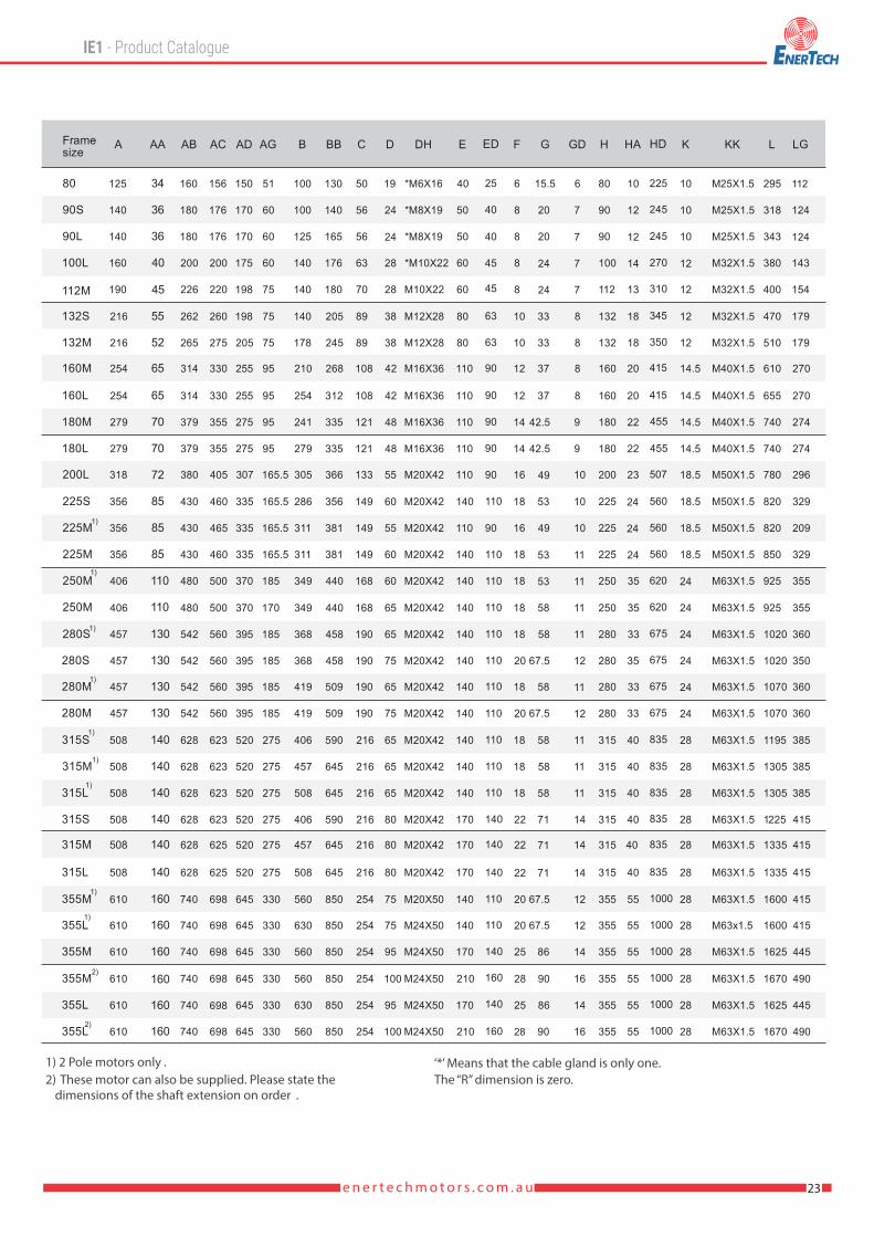
‘*’ Means that the cable gland is only one.1) 2 Pole motors only .2) These motor can also be supplied. Please state the
dimensions of the shaft extension on order .The “R” dimension is zero.

M
24 e n e r t e c h m o t o r s . c o m . a u
B
BB
LG
E
AC
2x-KK
ED
LA
FDH
D
GG
D
FDH
D
GG
D
FDH
D
GG
D
FDH
D
GG
D
T
L
NP
R C
BBB
LG
E
AC
2-KK
ED
LA
T
L
NP
C
B
BB
LG
E
AC
2xKK
ED
LA
T
L
NP
C
BBB
LG
E
AC
2xKK
ED
LA
T
L
NP
KC
AD
AG
HD
H
HA
K
A
AB
AA
S
M
AD
AG
HD
HH
A
K
A
AB
AA
S
MAD
AGH
D
H
KA
AB
AA
S
M
AD
AG
HD
H
HA
KA
AB
AA
S
125
140
140
160
190
216
216
254
254
279
279
318
356
356
356
406
406
457
457
457
457
508
508
508
508
508
508
610
610
610
610
610
610
A
34
36
36
40
45
55
52
65
65
70
70
72
85
85
85
110
110
130
130
130
130
140
140
140
140
140
140
160
160
160
160
160
160
160
180
180
200
226
262
265
314
314
379
379
380
430
430
430
480
480
542
542
542
542
628
628
628
628
628
628
740
740
740
740
740
740
AB AA
156
176
176
200
220
260
275
330
330
355
355
405
460
465
460
500
500
560
560
560
560
623
623
623
623
625
625
698
698
698
698
698
698
AC
150
170
170
175
198
198
205
255
255
275
275
307
335
335
335
370
370
395
395
395
395
520
520
520
520
520
520
645
645
645
645
645
645
AD
100
100
125
140
140
140
178
210
254
241
279
286
305
311
311
349
349
368
368
630
419
419
406
457
508
406
457
508
560
560
560
630
560
B
130
140
165
176
180
205
245
268
335
312
335
366
356
381
381
440
440
458
458
509
509
590
645
645
590
645
645
850
850
850
850
850
850
BB
50
56
56
63
70
89
89
108
108
121
121
133
149
149
149
168
168
190
190
190
190
216
216
216
216
216
216
254
254
254
254
254
254
C
19
24
24
28
28
38
38
42
42
48
48
55
55
75
75
80
80
60
60
60
65
65
65
65
65
65
80
75
75
95
95
100
100
D
*M6X16
*M8X19
*M8X19
*M10X22
M10X22
M12X28
M12X28
M16X36
M16X36
M16X36
M16X36
M20X42
M20X42
M20X42
M20X42
M20X42
M20X42
M20X42
M20X42
M20X42
M20X42
M20X42
M20X42
M20X42
M20X42
M20X42
M20X42
M20X50
M24X50
M24X50
M24X50
M24X50
M24X50
DH
40
50
50
60
60
80
80
110
110
110
110
110
140
110
140
140
140
140
140
140
140
140
140
140
170
170
170
140
140
170
170
210
210
E
25
40
40
45
45
63
63
90
90
90
90
90
110
90
110
110
110
110
110
110
110
110
110
110
140
140
140
110
110
140
160
140
160
ED
6
8
8
8
8
10
10
12
12
14
14
16
18
16
18
18
18
18
20
20
18
18
18
18
22
22
22
20
20
25
28
25
28
F
15.5
86
42.5
42.5
20
20
24
24
33
33
37
37
49
49
67.5
53
53
53
58
58
58
58
58
58
71
71
71
67.5
67.5
67.5
86
90
90
G
6
7
7
7
7
8
8
8
8
9
9
10
10
10
11
11
11
11
12
11
12
11
11
11
14
14
14
12
12
14
16
14
16
GD
80
90
90
100
112
132
132
160
160
180
180
200
225
225
225
250
250
280
280
280
280
315
315
315
315
315
315
355
355
355
355
355
355
H
10
12
12
14
13
18
18
20
20
22
22
23
24
24
24
35
35
33
35
33
33
40
40
40
40
40
40
55
55
55
55
55
55
HA
225
245
245
270
310
345
345
415
415
455
455
507
560
560
560
620
620
675
675
675
675
835
835
835
835
835
835
1000
1000
1000
1000
1000
1000
HD
18.5
18.5
14.5
14.5
14.5
14.5
18.5
18.5
10
10
10
12
12
12
12
24
24
24
24
24
24
28
28
28
28
28
28
28
28
28
28
28
28
K
M25X1.5
M25X1.5
M25X1.5
M32X1.5
M32X1.5
M32X1.5
M32X1.5
M40X1.5
M40X1.5
M40X1.5
M40X1.5
M50X1.5
M50X1.5
M50X1.5
M50X1.5
M63X1.5
M63X1.5
M63X1.5
M63X1.5
M63X1.5
M63X1.5
M63X1.5
M63X1.5
M63X1.5
M63X1.5
M63X1.5
M63X1.5
M63X1.5
M63x1.5
M63X1.5
M63X1.5
M63X1.5
M63X1.5
KK
112
124
124
143
154
179
179
270
270
274
274
296
329
209
329
355
355
360
350
360
360
385
385
385
415
415
415
415
415
445
490
445
490
LG
295
318
343
380
400
470
510
610
655
740
740
780
820
820
850
925
925
1020
1020
1070
1070
1195
1305
1305
1225
1335
1335
1600
1600
1625
1670
1625
1670
L
12
12
12
12
12
14
14
15
15
18
18
18
20
20
20
22
22
22
22
22
22
24
24
24
24
24
24
25
25
25
25
25
25
LA
165
165
165
215
215
265
265
300
300
300
300
350
400
400
400
500
500
500
500
500
500
600
650
600
600
600
600
740
740
740
740
740
740
M
130
130
130
180
180
230
230
250
250
250
250
300
350
350
350
450
450
450
450
450
450
550
550
450
550
550
550
680
680
680
680
680
680
N
200
200
200
250
250
300
300
350
350
350
350
400
450
450
450
550
550
550
550
550
550
660
660
550
660
660
660
800
800
800
800
800
800
P
12
12
12
14.5
14.5
14.5
14.5
18.5
18.5
18.5
18.5
18.5
18.5
18.5
18.5
18.5
18.5
18.5
18.5
18.5
18.5
24
24
24
24
24
24
24
24
24
24
24
24
S
3.5
3.5
3.5
4
4
4
4
5
5
5
5
5
5
5
5
5
5
5
5
5
5
5
5
5
6
6
6
6
6
6
6
6
6
TAG
51
60
60
60
75
75
75
95
95
95
95
165.5
165.5
165.5
165.5
185
170
185
185
185
185
275
275
275
275
275
275
330
330
330
330
330
330
Framesize
80
90S
90L
100L
112M
132S
132M
160M
160L
180M
180L
200L
225S
225M
250M
280S
280M
315S
315M
315L
355M
355L
225M1)
250M1)
280S1)
280M1)
315S1)
315M1)
315L1)
355M1)
355L1)
355M2)
355L2)
25e n e r t e c h m o t o r s . c o m . a u
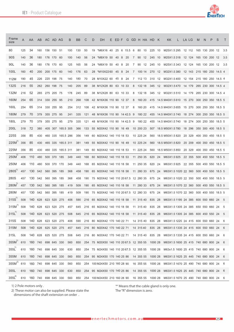
‘*’ Means that the cable gland is only one.1) 2 Pole motors only .2) These motor can also be supplied. Please state the
dimensions of the shaft extension on order .The “R” dimension is zero.
SM
AG
AD
FDH
D
GG
D
FDH
D
GG
D
FDH
D
GG
D
FDH
D
GG
D
SM
AG
AD
S
M
AG
AD
S
M
AG
AD
S
M
AG
AD
26 e n e r t e c h m o t o r s . c o m . a u
R
LG
E
AC
2xKK
ED
LA
T
L
NP
LG
E
AC
2-KK
ED
LA
T
L
N P
C
LG
E
AC
2-KK
ED
LA
T
L
NP
LG
E
AC
2xKK
ED
LA
T
L
NP

27e n e r t e c h m o t o r s . c o m . a u
‘*’ Means that the cable gland is only one.1) 2 Pole motors only.2) These motor can also be supplied. Please state the
dimensions of the shaft extension on order.The “R” dimension is zero.
156
176
176
200
220
260
275
330
330
355
355
405
460
465
460
500
500
560
560
560
560
623
623
623
623
625
625
698
698
698
698
698
698
AC
150
170
170
175
198
198
205
255
255
275
275
307
335
335
335
370
370
395
395
395
395
520
520
520
520
520
520
645
645
645
645
645
645
AD
19
24
24
28
28
38
38
42
42
48
48
55
55
75
75
80
80
60
60
60
65
65
65
65
65
65
80
75
75
95
95
100
100
D
*M6X16
*M8X19
*M8X19
*M10X22
M10X22
M12X28
M12X28
M16X36
M16X36
M16X36
M16X36
M20X42
M20X42
M20X42
M20X42
M20X42
M20X42
M20X42
M20X42
M20X42
M20X42
M20X42
M20X42
M20X42
M20X42
M20X42
M20X42
M20X50
M24X50
M24X50
M24X50
M24X50
M24X50
DH
40
50
50
60
60
80
80
110
110
110
110
110
140
110
140
140
140
140
140
140
140
140
140
140
170
170
170
140
140
170
170
210
210
E
25
40
40
45
45
63
63
90
90
90
90
90
110
90
110
110
110
110
110
110
110
110
110
110
140
140
140
110
110
140
160
140
160
ED
6
8
8
8
8
10
10
12
12
14
14
16
18
16
18
18
18
18
20
20
18
18
18
18
22
22
22
20
20
25
28
25
28
F
15.5
86
42.5
42.5
20
20
24
24
33
33
37
37
49
49
67.5
53
53
53
58
58
58
58
58
58
71
71
71
67.5
67.5
67.5
86
90
90
G
6
7
7
7
7
8
8
8
8
9
9
10
10
10
11
11
11
11
12
11
12
11
11
11
14
14
14
12
12
14
16
14
16
GD
M25X1.5
M25X1.5
M25X1.5
M32X1.5
M32X1.5
M32X1.5
M32X1.5
M40X1.5
M40X1.5
M40X1.5
M40X1.5
M50X1.5
M50X1.5
M50X1.5
M50X1.5
M63X1.5
M63X1.5
M63X1.5
M63X1.5
M63X1.5
M63X1.5
M63X1.5
M63X1.5
M63X1.5
M63X1.5
M63X1.5
M63X1.5
M63X1.5
M63x1.5
M63X1.5
M63X1.5
M63X1.5
M63X1.5
KK
112
124
124
143
154
179
179
270
270
274
274
296
329
209
329
355
355
360
350
360
360
385
385
385
415
415
415
415
415
445
490
445
490
LG
295
318
343
380
400
470
510
610
655
740
740
780
820
820
850
925
925
1020
1020
1070
1070
1 195
1305
1305
1 225
1335
1335
1600
1600
1625
1670
1625
1670
L
12
12
12
12
12
14
14
15
15
18
18
18
20
20
20
22
22
22
22
22
22
24
24
24
24
24
24
25
25
25
25
25
25
LA
165
165
165
215
215
265
265
300
300
300
300
350
400
400
400
500
500
500
500
500
500
600
650
600
600
600
600
740
740
740
740
740
740
M
130
130
130
180
180
230
230
250
250
250
250
300
350
350
350
450
450
450
450
450
450
550
550
450
550
550
550
680
680
680
680
680
680
N
200
200
200
250
250
300
300
350
350
350
350
400
450
450
450
550
550
550
550
550
550
660
660
550
660
660
660
800
800
800
800
800
800
P
12
12
12
14.5
14.5
14.5
14.5
18.5
18.5
18.5
18.5
18.5
18.5
18.5
18.5
18.5
18.5
18.5
18.5
18.5
18.5
24
24
24
24
24
24
24
24
24
24
24
24
S
3.5
3.5
3.5
4
4
4
4
5
5
5
5
5
5
5
5
5
5
5
5
5
5
5
5
5
6
6
6
6
6
6
6
6
6
TAG
51
60
60
60
75
75
75
95
95
95
95
165.5
165.5
165.5
165.5
185
170
185
185
185
185
275
275
275
275
275
275
330
330
330
330
330
330
Framesize
80
90S
90L
100L
112M
132S
132M
160M
160L
180M
180L
200L
225S
225M
250M
280S
280M
315S
315M
315L
355M
355L
225M1)
250M1)
280S1)
280M1)
315S1)
315M1)
315L1)
355M1)
355L1)
355M2)
355L2)

28 e n e r t e c h m o t o r s . c o m . a u
‘*’ Means that the cable gland is only one.The “R” dimension is zero.
29e n e r t e c h m o t o r s . c o m . a u

e n e r t e c h m o t o r s . c o m . a u
Operation and Maintenance
30

(Horizontal)
(Horizontal)
(Horizontal)
(Horizontal)
(Vertical)
(Vertical)
(Vertical)
(Vertical)
31e n e r t e c h m o t o r s . c o m . a u

It should be noted that for motor �tted with Ball and Roller bearing, the lubrication invervals for both bearings should be based on the
roller bearing data. The lubrication intervals recommend are calculated on the basis of normal working conditions (operating
temperatures up to 70°C). - ESC motors are equipped with bearings from excellent manufactures. We recommend to use SKF, FAG or
NSK Brand. - In general the bearings have C3 clearances. - Motor of frame size 80-132 are �tted with life-lubricated bearings. - Motor of
frame size 160-355 are �tted with open bearings and regreasing device. Depending on the useful life of grease, open bearings must
be regreased in good time so that the scheduled bearing service life is reached. We recommend to use Shell Gadus S3 V220C-2 and BP
Energrease LS2. - Angular contact thrust ball bearings should be used for vertical mounting motor.
Notes:* 2 Pole motors only1. Vertical motors should be greased twice as often as horizontal motors.2. Regreasing time should be reduced if bearing operating temperature is in excess of 70 C
1. Oil seal
3. Flange2. Endshield D.E
4. Key5. Bearing6. Rotor
7. Bearing N.D.E8. Terminal Board9. Stator
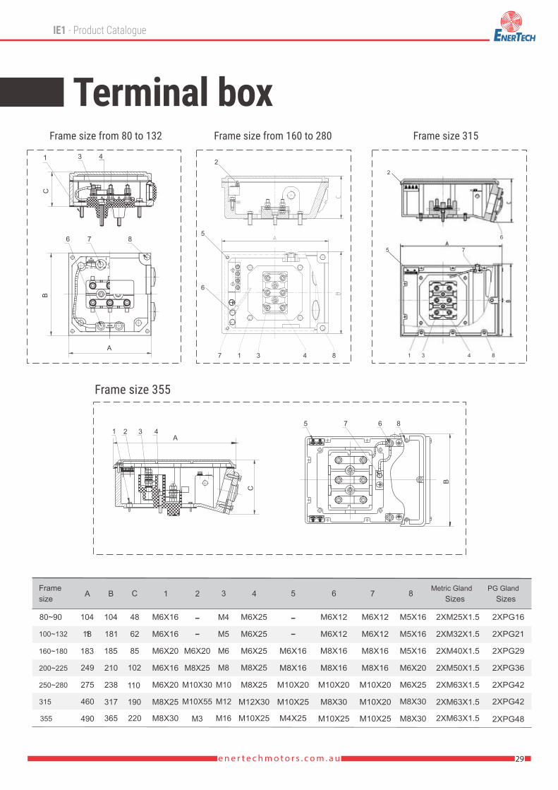
10. Terminal Box Lid
11. Terminal Box Base12. Fan Cowl13. Fan14. Endshield N.D.E
32 e n e r t e c h m o t o r s . c o m . a u

Vibration severity limit Level.
Description Comments Maintenance FrequencyMotor use/sequencing
Weekly
Weekly
Weekly
Weekly
Quarterly (or as neededon weekly inspections)
Quarterly
Annually (or based on run hours)
Overall visual inspection
Check bearings and drive belts
.
Motor alignment
Motor condition
Cleaning
Check lubrication
Check mountings Annually
Check terminal tightness Annually
Check for balanced three-phase power Annually
Check for over- or undervoltage conditions
Turn o� or sequence unnecessary motors.
Verify equipment is operating and safety systems are in place.
Inspect for wear, and adjust, repair, or replace as necessary.
Look for rubber or steel savings under couplings, or listen forodd noises, as these may indicate a problem).Check condition by analyzing temperature or vibration, and compareto baseline values.
Remove dust and dirt to facilitate cooling.
Ensure bearings are lubricated as recommended by manufacturer.
Secure any loose mountings.
Tighten any loose connections.Troubleshoot unbalanced motor circuit and �xproblems if the voltage imbalance exceeds 1%.
Troubleshoot motor circuit and �x problems if thesupply voltage di�ers signi�cantly from rated voltages.
Annually
Vibration severity limit Level.
ESC motor fall within the limits of vibration severity set out in standard IEC 60034-14 which are listed below. As speci�ed in the standard, these values ralate to rotating machinery measured in soft suspension. Vibration severity limit Level.B
Vibration
Rotors have been dynamically balanced with a haft key. Pulleys or couplings used with motors must also be appropriate
Balancing
Noise levels for ESC motor comply with limits set by IEC 60034.9 and AS1359.109. ESC sound pressure levels at 1 metre (Data relate to motor tested at no load) are set out in the.)
Noise
MAINTENANCE SCHEDULE FOR MOTORS
33e n e r t e c h m o t o r s . c o m . a u
• Before running the motor make sure that the terminal box lid is closed and secured with appropriate clearance to live parts.• Make sure that appropriate earthing is done.• Make sure that the coupling and/or transmission is adequately guarded for safety.• Check the mounting bolts and/or flanges are firmly secured.• Make sure of no loose objects around that may be sucked by the cooling fan on the motor.• Make sure that the load applied is within the nameplate specification.• Make sure that the ambient temperature is inside 40°C or nameplate specification, record the figures in the log book for future reference.Note that the current imbalance can be higher, typically 10 times the voltage imbalance if there is an imbalance in supply voltage.
OPERATION
Vibration severity limit Level.VIBRATION, BALANCING ANH NOISE
Sound pressure level

34 e n e r t e c h m o t o r s . c o m . a u
The ESC series can be modi�ed to incorporate one or more of the following options, please contact your nearest. Please contact to Enertech Electric motor (Australia) branch for more details.
• Socket head cap screws, Grades 8.8, 10.9 or 12.9 to replace all external bolts and/or screws.• Anti-condensation heater terminated in the main terminal box.• Stainless steel shafts.• Alternative shaft diameters and/or shaft length.• Double shaft extensions.• Alternative conduit entry dimensions.• Alternative bearing arrangements (ball, roller, angular contact or four point contact types).• Force ventilation for frame size 200 and above.• Low noise fan and cowl in steel or cowl only in stainless steel.• Rain canopy for vertical mount (V1) in steel or stainless steel.• Class H winding insulation.• Nonstandard paint color in RAL standard.Two pack epoxy paint �nish.
• Class H winding insulation for 180°C working environment.• PTC and condensate heater (optional).• Grease nipple both DE and NDE bearing for frame size 100L, 112M and 132) if required. IQF Spiral Freezer & Cooler• Especial design for IQF tunner freezer condition.• Working temperature -49°C max.• IPSS with Anti-condensation heater terminated in main terminal box.• IP 66 (optional).• Double shaft extension.• Anodizing of aluminium or enhanced performance cast iron units.• Stainless steel external shaft (optional).• Air Blast Freezer• Stainless steel external in grades AISI 316L. Working in temperature from -18°C to22°C.
4 Pole - 1500 rpm asynchronous speed 50Hz
1500r/min = 4 poles
Stainless Steel casting for Freezer Air Coolers
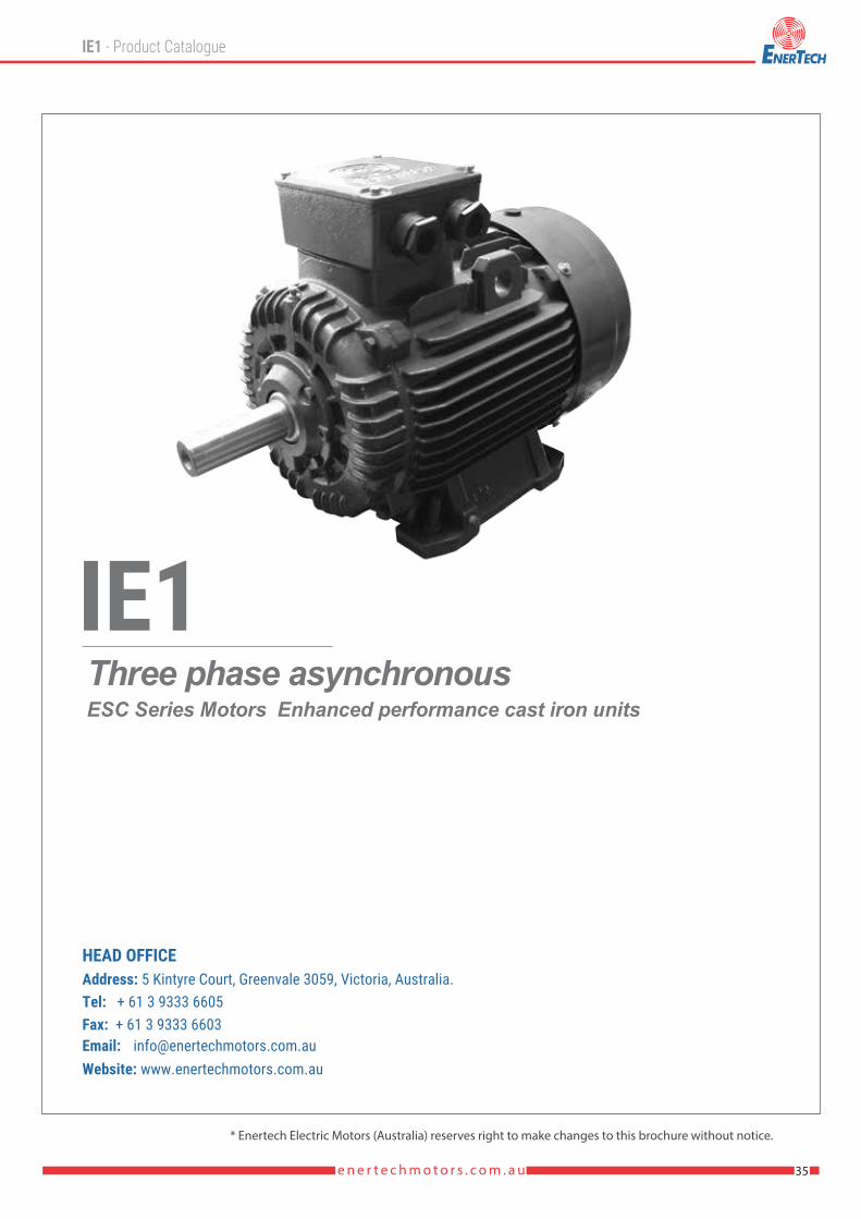
Three phase asynchronousESC Series Motors Enhanced performance cast iron units
35e n e r t e c h m o t o r s . c o m . a u
* Enertech Electric Motors (Australia) reserves right to make changes to this brochure without notice.
