esd suppressor selection guide
TRANSCRIPT

Modified_030108
CIRCUIT
PROTECTION
SOLUTIONS
Confidential and Proprietary to Littelfuse, Inc. ® Littelfuse, Inc. 2008. All rights reserved.
Using the ESD Selection Guide
• Change to “presentation mode” to activate links
• The selection guide is driven from the next slide
• To learn about protection with a specific technology, click on
the respective circuit in the “Applications and Circuits” column
• For an overview of each ESD technology, click on the
respective technology link
Click here to go to the
ESD selection chart
Modified_030108
CIRCUIT
PROTECTION
SOLUTIONS
Confidential and Proprietary to Littelfuse, Inc. ® Littelfuse, Inc. 2008. All rights reserved.
Protection
Technology
Data
Rate
Peak/clamp
(8kV)
ESD
Level
Discrete
Options
Array
Options
Applications
and Circuits
Relative
Cost
Key
Advantage
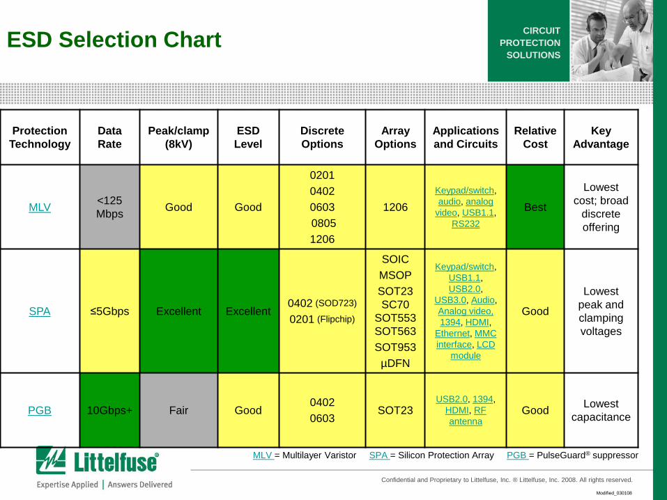
MLV<125
MbpsGood Good
0201
0402
0603
0805
1206
1206
Keypad/switch,
audio, analog
video, USB1.1,
RS232
Best
Lowest
cost; broad
discrete
offering
SPA ≤5Gbps Excellent Excellent0402 (SOD723)
0201 (Flipchip)
SOIC
MSOP
SOT23
SC70
SOT553
SOT563
SOT953
µDFN
Keypad/switch,
USB1.1,
USB2.0,
USB3.0, Audio,
Analog video,
1394, HDMI,
Ethernet, MMC
interface, LCD
module
Good
Lowest
peak and
clamping
voltages
PGB 10Gbps+ Fair Good0402
0603SOT23
USB2.0, 1394,
HDMI, RF
antennaGood
Lowest
capacitance
MLV = Multilayer Varistor SPA = Silicon Protection Array PGB = PulseGuard® suppressor
ESD Selection Chart
Modified_030108
CIRCUIT
PROTECTION
SOLUTIONS
Confidential and Proprietary to Littelfuse, Inc. ® Littelfuse, Inc. 2008. All rights reserved.
Click here to return to
ESD selection chart

Modified_030108
CIRCUIT
PROTECTION
SOLUTIONS
Confidential and Proprietary to Littelfuse, Inc. ® Littelfuse, Inc. 2008. All rights reserved.
ESD suppressor introduction slides

Modified_030108
CIRCUIT
PROTECTION
SOLUTIONS
Confidential and Proprietary to Littelfuse, Inc. ® Littelfuse, Inc. 2008. All rights reserved.
Multilayer Varistor (MLV)
• Solution for ESD; can also provide limited
(~20dB) EMI filtering
• Sizes range from 0201 to 1210
• Capacitance values from 3 pF to 4,500 pF
• Operating voltage from 5.5VDC to 120VDC
• Single-line and quad-channel packages
• Key feature is that a wide range of discrete
form factors to match PCB real estate
availability; capacitance values can be
matched to the circuit to provide EMI filtering
Return to Selection Chart
ESD suppression – Multilayer Varistor
Modified_030108
CIRCUIT
PROTECTION
SOLUTIONS
Confidential and Proprietary to Littelfuse, Inc. ® Littelfuse, Inc. 2008. All rights reserved.
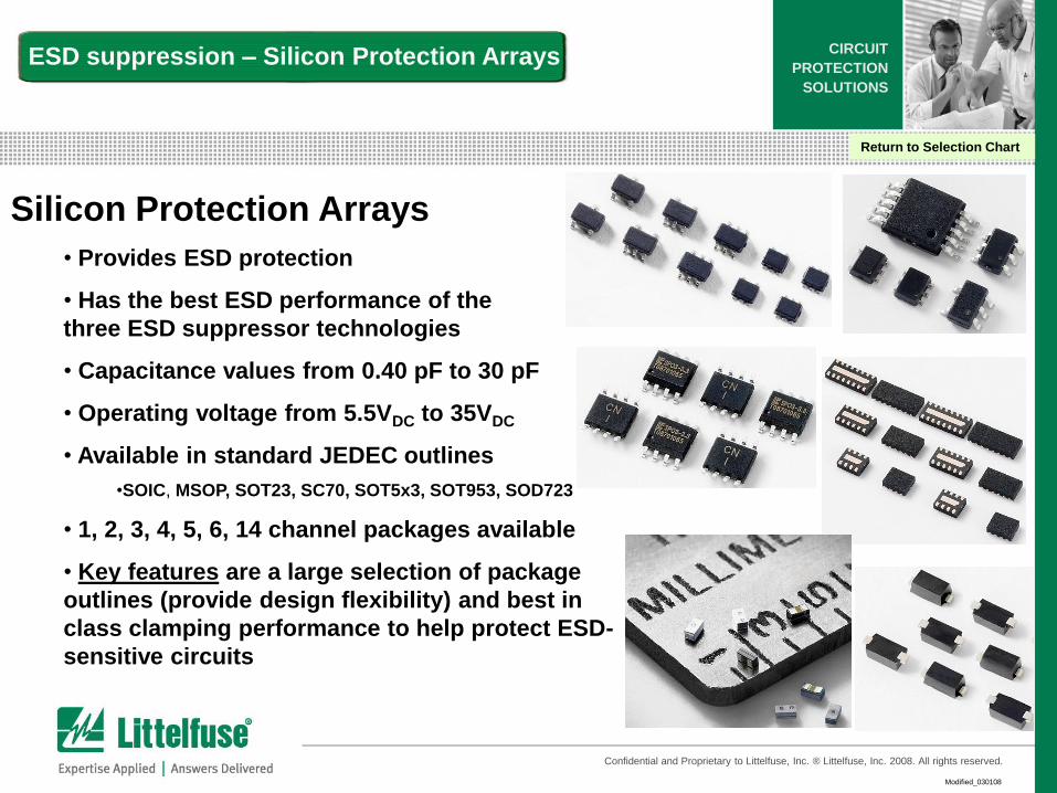
Silicon Protection Arrays
• Provides ESD protection
• Has the best ESD performance of the
three ESD suppressor technologies
• Capacitance values from 0.40 pF to 30 pF
• Operating voltage from 5.5VDC to 35VDC
• Available in standard JEDEC outlines
•SOIC, MSOP, SOT23, SC70, SOT5x3, SOT953, SOD723
• 1, 2, 3, 4, 5, 6, 14 channel packages available
• Key features are a large selection of package
outlines (provide design flexibility) and best in
class clamping performance to help protect ESD-
sensitive circuits
ESD suppression – Silicon Protection Arrays
Return to Selection Chart
Modified_030108
CIRCUIT
PROTECTION
SOLUTIONS
Confidential and Proprietary to Littelfuse, Inc. ® Littelfuse, Inc. 2008. All rights reserved.
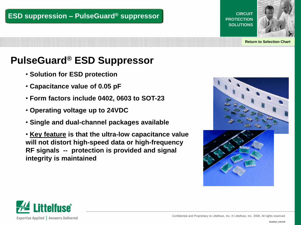
PulseGuard® ESD Suppressor
• Solution for ESD protection
• Capacitance value of 0.05 pF
• Form factors include 0402, 0603 to SOT-23
• Operating voltage up to 24VDC
• Single and dual-channel packages available
• Key feature is that the ultra-low capacitance value
will not distort high-speed data or high-frequency
RF signals -- protection is provided and signal
integrity is maintained
ESD suppression – PulseGuard® suppressor
Return to Selection Chart

Modified_030108
CIRCUIT
PROTECTION
SOLUTIONS
Confidential and Proprietary to Littelfuse, Inc. ® Littelfuse, Inc. 2008. All rights reserved.
Silicon Protection Array slides
Return to Selection Chart
10
Version01_100407
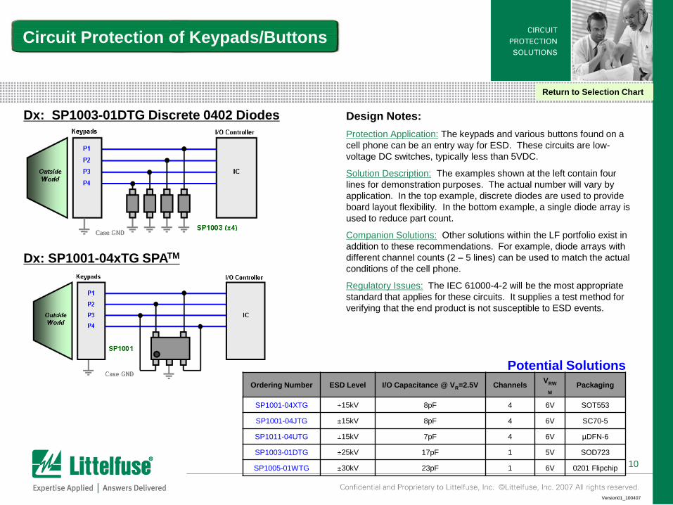
Circuit Protection of Keypads/Buttons
Dx: SP1003-01DTG Discrete 0402 Diodes
Dx: SP1001-04xTG SPATM
Design Notes:
Protection Application: The keypads and various buttons found on a
cell phone can be an entry way for ESD. These circuits are low-
voltage DC switches, typically less than 5VDC.
Solution Description: The examples shown at the left contain four
lines for demonstration purposes. The actual number will vary by
application. In the top example, discrete diodes are used to provide
board layout flexibility. In the bottom example, a single diode array is
used to reduce part count.
Companion Solutions: Other solutions within the LF portfolio exist in
addition to these recommendations. For example, diode arrays with
different channel counts (2 – 5 lines) can be used to match the actual
conditions of the cell phone.
Regulatory Issues: The IEC 61000-4-2 will be the most appropriate
standard that applies for these circuits. It supplies a test method for
verifying that the end product is not susceptible to ESD events.
Return to Selection Chart
Ordering Number ESD Level I/O Capacitance @ VR=2.5V ChannelsVRW
M
Packaging
SP1001-04XTG 15kV 8pF 4 6V SOT553
SP1001-04JTG 15kV 8pF 4 6V SC70-5
SP1011-04UTG 15kV 7pF 4 6V µDFN-6
SP1003-01DTG 25kV 17pF 1 5V SOD723
SP1005-01WTG 30kV 23pF 1 6V 0201 Flipchip
Potential Solutions
11
Version01_100407
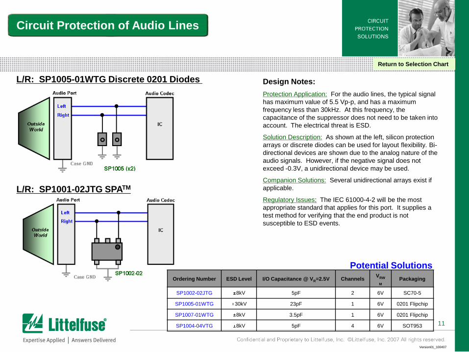
L/R: SP1001-02JTG SPATM
L/R: SP1005-01WTG Discrete 0201 Diodes
Circuit Protection of Audio Lines
Design Notes:
Protection Application: For the audio lines, the typical signal
has maximum value of 5.5 Vp-p, and has a maximum
frequency less than 30kHz. At this frequency, the
capacitance of the suppressor does not need to be taken into
account. The electrical threat is ESD.
Solution Description: As shown at the left, silicon protection
arrays or discrete diodes can be used for layout flexibility. Bi-
directional devices are shown due to the analog nature of the
audio signals. However, if the negative signal does not
exceed -0.3V, a unidirectional device may be used.
Companion Solutions: Several unidirectional arrays exist if
applicable.
Regulatory Issues: The IEC 61000-4-2 will be the most
appropriate standard that applies for this port. It supplies a
test method for verifying that the end product is not
susceptible to ESD events.
Return to Selection Chart
Ordering Number ESD Level I/O Capacitance @ VR=2.5V ChannelsVRW
M
Packaging
SP1002-02JTG 8kV 5pF 2 6V SC70-5
SP1005-01WTG 30kV 23pF 1 6V 0201 Flipchip
SP1007-01WTG 8kV 3.5pF 1 6V 0201 Flipchip
SP1004-04VTG 8kV 5pF 4 6V SOT953
Potential Solutions
12
Version01_100407
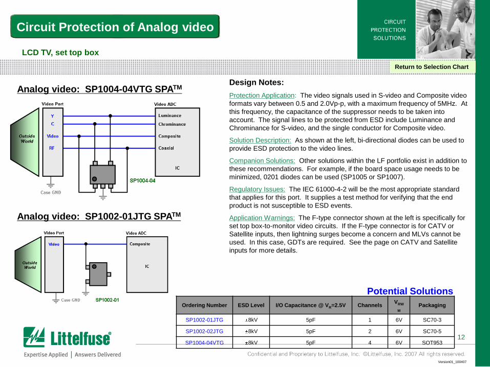
Design Notes:
Protection Application: The video signals used in S-video and Composite video
formats vary between 0.5 and 2.0Vp-p, with a maximum frequency of 5MHz. At
this frequency, the capacitance of the suppressor needs to be taken into
account. The signal lines to be protected from ESD include Luminance and
Chrominance for S-video, and the single conductor for Composite video.
Solution Description: As shown at the left, bi-directional diodes can be used to
provide ESD protection to the video lines.
Companion Solutions: Other solutions within the LF portfolio exist in addition to
these recommendations. For example, if the board space usage needs to be
minimized, 0201 diodes can be used (SP1005 or SP1007).
Regulatory Issues: The IEC 61000-4-2 will be the most appropriate standard
that applies for this port. It supplies a test method for verifying that the end
product is not susceptible to ESD events.
Application Warnings: The F-type connector shown at the left is specifically for
set top box-to-monitor video circuits. If the F-type connector is for CATV or
Satellite inputs, then lightning surges become a concern and MLVs cannot be
used. In this case, GDTs are required. See the page on CATV and Satellite
inputs for more details.
Circuit Protection of Analog video
Analog video: SP1004-04VTG SPATM
LCD TV, set top box
Return to Selection Chart
Ordering Number ESD Level I/O Capacitance @ VR=2.5V ChannelsVRW
M
Packaging
SP1002-01JTG 8kV 5pF 1 6V SC70-3
SP1002-02JTG 8kV 5pF 2 6V SC70-5
SP1004-04VTG 8kV 5pF 4 6V SOT953
Potential Solutions
Analog video: SP1002-01JTG SPATM
13
Version01_100407
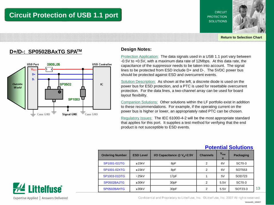
D+/D-: SP0502BAxTG SPATM Design Notes:
Protection Application: The data signals used in a USB 1.1 port vary between
-0.5V to +0.5V, with a maximum data rate of 12Mbps. At this data rate, the
capacitance of the suppressor needs to be taken into account. The signal
lines to be protected from ESD include D+ and D-. The 5VDC power bus
should be protected against ESD and overcurrent events.
Solution Description: As shown at the left, a discrete diode is used on the
power bus for ESD protection, and a PTC is used for resettable overcurrent
protection. For the data lines, a two-channel array can be used for board
layout flexibility.
Companion Solutions: Other solutions within the LF portfolio exist in addition
to these recommendations. For example, if the operating current on the
power bus is higher or lower, an appropriately rated PTC can be chosen.
Regulatory Issues: The IEC 61000-4-2 will be the most appropriate standard
that applies for this port. It supplies a test method for verifying that the end
product is not susceptible to ESD events.
Circuit Protection of USB 1.1 port
Return to Selection Chart
Ordering Number ESD Level I/O Capacitance @ VR=2.5V ChannelsVRW
M
Packaging
SP1001-02JTG 15kV 8pF 2 6V SC70-3
SP1001-02XTG 15kV 8pF 2 6V SOT553
SP1003-01DTG 25kV 17pF 1 5V SOD723
SP0502BAJTG 30kV 30pF 2 5.5V SC70-3
SP0502BAHTG 30kV 30pF 2 5.5V SOT23-3
Potential Solutions
14
Version01_100407
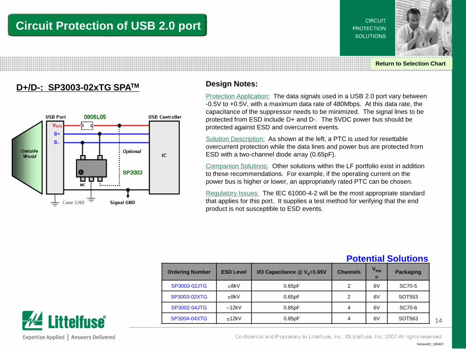
D+/D-: SP3003-02xTG SPATM Design Notes:
Protection Application: The data signals used in a USB 2.0 port vary between
-0.5V to +0.5V, with a maximum data rate of 480Mbps. At this data rate, the
capacitance of the suppressor needs to be minimized. The signal lines to be
protected from ESD include D+ and D-. The 5VDC power bus should be
protected against ESD and overcurrent events.
Solution Description: As shown at the left, a PTC is used for resettable
overcurrent protection while the data lines and power bus are protected from
ESD with a two-channel diode array (0.65pF).
Companion Solutions: Other solutions within the LF portfolio exist in addition
to these recommendations. For example, if the operating current on the
power bus is higher or lower, an appropriately rated PTC can be chosen.
Regulatory Issues: The IEC 61000-4-2 will be the most appropriate standard
that applies for this port. It supplies a test method for verifying that the end
product is not susceptible to ESD events.
Circuit Protection of USB 2.0 port
Return to Selection Chart
Ordering Number ESD Level I/O Capacitance @ VR=1.65V ChannelsVRW
M
Packaging
SP3003-02JTG 8kV 0.65pF 2 6V SC70-5
SP3003-02XTG 8kV 0.65pF 2 6V SOT553
SP3002-04JTG 12kV 0.85pF 4 6V SC70-6
SP3004-04XTG 12kV 0.85pF 4 6V SOT563
Potential Solutions

15
Version01_100407
D± & SSRX/TX±: SP3010-04UTG SPATMDesign Notes:
Protection Application: USB3.0 adds two new data pair to the legacy D+/D-
pair namely SSTX+, SSTX-, SSRX+, and SSRX-. These new super-speed
lines will operate at a maximum data rate of 5Gbps while the old D+/D- will
operate at a maximum of 480Mbps. At these data rates, the capacitance of
the suppressor needs to be minimized. The signal lines need to be protected
from ESD, and the 5VDC power bus should be protected against ESD and
overcurrent events.
Solution Description: As shown at the upper left, a PTC is used for resettable
overcurrent protection while the super-speed data lines are protected with an
ultra-low capacitance diode array. Furthermore, another diode array is used
for ESD protection of D+/D- as well as the power bus.
Companion Solutions: Other solutions within the LF portfolio exist such a fully
integrated six channel protection array (lower left) to further minimize part
count and simply the board design.
Regulatory Issues: The IEC 61000-4-2 will be the most appropriate standard
that applies for this port. It supplies a test method for verifying that the end
product is not susceptible to ESD events.
Circuit Protection of USB 3.0 port
Return to Selection Chart
Ordering Number ESD Level I/O Capacitance @ VR=1.65V ChannelsVRW
M
Packaging
SP3010-04UTG 8kV 0.45pF 4 6V µDFN-10
SP3003-02XTG 8kV 0.65pF 2 6V SOT553
SP3011-06UTG 8kV 0.40pF 4 6V µDFN-14
Potential Solutions
D± & SSRX/TX±: SP3011-06UTG SPATM
16
Version01_100407
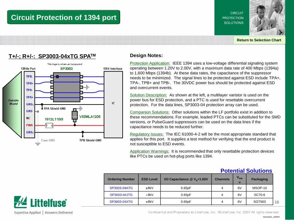
Design Notes:
Protection Application: IEEE 1394 uses a low-voltage differential signaling system
operating between 1.20V to 2.00V, with a maximum data rate of 400 Mbps (1394a)
to 1,600 Mbps (1394b). At these data rates, the capacitance of the suppressor
needs to be minimized. The signal lines to be protected against ESD include TPA+,
TPA-, TPB+ and TPB-. The 30VDC power bus should be protected against ESD
and overcurrent events.
Solution Description: As shown at the left, a multilayer varistor is used on the
power bus for ESD protection, and a PTC is used for resettable overcurrent
protection. For the data lines, SP3003-04 protection array can be used.
Companion Solutions: Other solutions within the LF portfolio exist in addition to
these recommendations. For example, leaded PTCs can be substituted for the SMD
versions, or PulseGuard suppressors can be used on the data lines if the
capacitance needs to be reduced further.
Regulatory Issues: The IEC 61000-4-2 will be the most appropriate standard that
applies for this port. It supplies a test method for verifying that the end product is
not susceptible to ESD events.
Application Warnings: It is recommended that only resettable protection devices
like PTCs be used on hot-plug ports like 1394.
T+/-; R+/-: SP3003-04xTG SPATM
Circuit Protection of 1394 port
Return to Selection Chart
Ordering Number ESD Level I/O Capacitance @ VR=1.65V ChannelsVRW
M
Packaging
SP3003-04ATG 8kV 0.65pF 4 6V MSOP-10
SP3003-04JTG 8kV 0.65pF 4 6V SC70-6
SP3003-04XTG 8kV 0.65pF 4 6V SOT563
Potential Solutions
17
Version01_100407
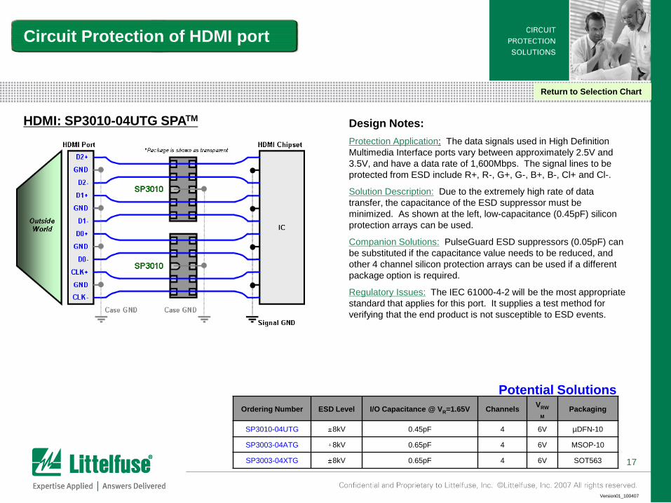
Design Notes:
Protection Application: The data signals used in High Definition
Multimedia Interface ports vary between approximately 2.5V and
3.5V, and have a data rate of 1,600Mbps. The signal lines to be
protected from ESD include R+, R-, G+, G-, B+, B-, Cl+ and Cl-.
Solution Description: Due to the extremely high rate of data
transfer, the capacitance of the ESD suppressor must be
minimized. As shown at the left, low-capacitance (0.45pF) silicon
protection arrays can be used.
Companion Solutions: PulseGuard ESD suppressors (0.05pF) can
be substituted if the capacitance value needs to be reduced, and
other 4 channel silicon protection arrays can be used if a different
package option is required.
Regulatory Issues: The IEC 61000-4-2 will be the most appropriate
standard that applies for this port. It supplies a test method for
verifying that the end product is not susceptible to ESD events.
HDMI: SP3010-04UTG SPATM
Circuit Protection of HDMI port
Return to Selection Chart
Ordering Number ESD Level I/O Capacitance @ VR=1.65V ChannelsVRW
M
Packaging
SP3010-04UTG 8kV 0.45pF 4 6V µDFN-10
SP3003-04ATG 8kV 0.65pF 4 6V MSOP-10
SP3003-04XTG 8kV 0.65pF 4 6V SOT563
Potential Solutions
18
Version01_100407
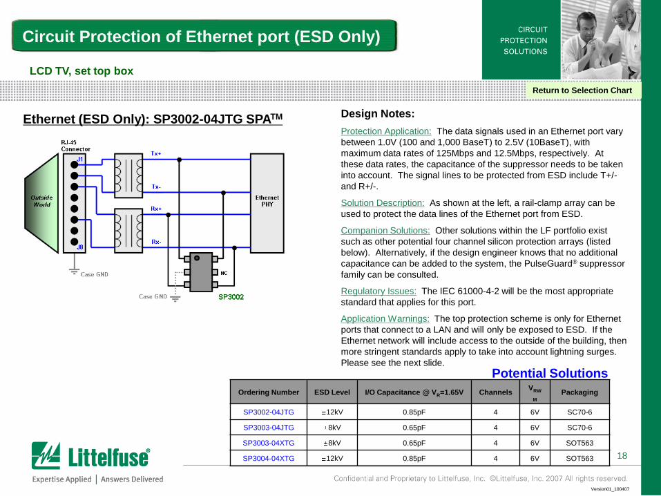
Design Notes:
Protection Application: The data signals used in an Ethernet port vary
between 1.0V (100 and 1,000 BaseT) to 2.5V (10BaseT), with
maximum data rates of 125Mbps and 12.5Mbps, respectively. At
these data rates, the capacitance of the suppressor needs to be taken
into account. The signal lines to be protected from ESD include T+/-
and R+/-.
Solution Description: As shown at the left, a rail-clamp array can be
used to protect the data lines of the Ethernet port from ESD.
Companion Solutions: Other solutions within the LF portfolio exist
such as other potential four channel silicon protection arrays (listed
below). Alternatively, if the design engineer knows that no additional
capacitance can be added to the system, the PulseGuard® suppressor
family can be consulted.
Regulatory Issues: The IEC 61000-4-2 will be the most appropriate
standard that applies for this port.
Application Warnings: The top protection scheme is only for Ethernet
ports that connect to a LAN and will only be exposed to ESD. If the
Ethernet network will include access to the outside of the building, then
more stringent standards apply to take into account lightning surges.
Please see the next slide.
Circuit Protection of Ethernet port (ESD Only)
LCD TV, set top box
Return to Selection Chart
Ethernet (ESD Only): SP3002-04JTG SPATM
Ordering Number ESD Level I/O Capacitance @ VR=1.65V ChannelsVRW
M
Packaging
SP3002-04JTG 12kV 0.85pF 4 6V SC70-6
SP3003-04JTG 8kV 0.65pF 4 6V SC70-6
SP3003-04XTG 8kV 0.65pF 4 6V SOT563
SP3004-04XTG 12kV 0.85pF 4 6V SOT563
Potential Solutions
19
Version01_100407
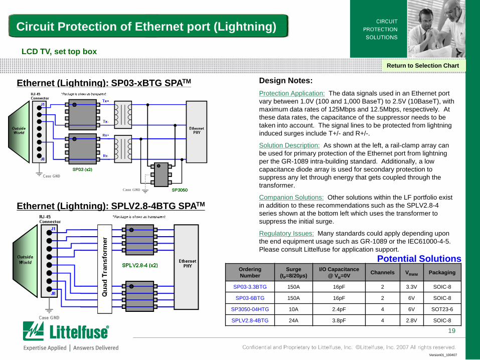
Design Notes:
Protection Application: The data signals used in an Ethernet port
vary between 1.0V (100 and 1,000 BaseT) to 2.5V (10BaseT), with
maximum data rates of 125Mbps and 12.5Mbps, respectively. At
these data rates, the capacitance of the suppressor needs to be
taken into account. The signal lines to be protected from lightning
induced surges include T+/- and R+/-.
Solution Description: As shown at the left, a rail-clamp array can
be used for primary protection of the Ethernet port from lightning
per the GR-1089 intra-building standard. Additionally, a low
capacitance diode array is used for secondary protection to
suppress any let through energy that gets coupled through the
transformer.
Companion Solutions: Other solutions within the LF portfolio exist
in addition to these recommendations such as the SPLV2.8-4
series shown at the bottom left which uses the transformer to
suppress the initial surge.
Regulatory Issues: Many standards could apply depending upon
the end equipment usage such as GR-1089 or the IEC61000-4-5.
Please consult Littelfuse for application support.
Circuit Protection of Ethernet port (Lightning)
LCD TV, set top box
Return to Selection Chart
Ethernet (Lightning): SP03-xBTG SPATM
Ordering
Number
Surge
(tP=8/20µs)
I/O Capacitance
@ VR=0VChannels VRWM Packaging
SP03-3.3BTG 150A 16pF 2 3.3V SOIC-8
SP03-6BTG 150A 16pF 2 6V SOIC-8
SP3050-04HTG 10A 2.4pF 4 6V SOT23-6
SPLV2.8-4BTG 24A 3.8pF 4 2.8V SOIC-8
Potential Solutions
Ethernet (Lightning): SPLV2.8-4BTG SPATM
20
Version01_100407
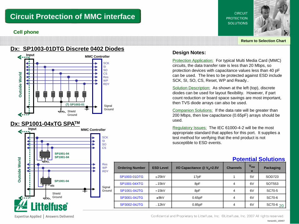
Design Notes:
Protection Application: For typical Multi Media Card (MMC)
circuits, the data transfer rate is less than 20 Mbps, so
protection devices with capacitance values less than 40 pF
can be used. The lines to be protected against ESD include
SCK, SI, SO, CS, Reset, WP and Ready..
Solution Description: As shown at the left (top), discrete
diodes can be used for layout flexibility. However, if part
count reduction or board space savings are most important,
then TVS diode arrays can also be used.
Companion Solutions: If the data rate will be greater than
200 Mbps, then low capacitance (0.65pF) arrays should be
used.
Regulatory Issues: The IEC 61000-4-2 will be the most
appropriate standard that applies for this port. It supplies a
test method for verifying that the end product is not
susceptible to ESD events.
Circuit Protection of MMC interface
Signal
Ground
Ou
tsid
e W
orl
d
SP1001-04
Shield
Ground
MMC ControllerInput
Res
WP
RDY
n/c
SCK
SI
SO
CS
SP1001-04
SP1001-04
Signal
Ground
Ou
tsid
e W
orl
d
Shield
Ground
MMC ControllerInput
SCK
SI
SO
CS
Res
WP
RDY
Dx: SP1003-01DTG Discrete 0402 Diodes
Dx: SP1001-04xTG SPATM
(7) SP1003-01
Cell phone
Return to Selection Chart
Ordering Number ESD Level I/O Capacitance @ VR=2.5V ChannelsVRW
M
Packaging
SP1003-01DTG 25kV 17pF 1 5V SOD723
SP1001-04XTG 15kV 8pF 4 6V SOT553
SP1001-04JTG 15kV 8pF 4 6V SC70-5
SP3001-04JTG 8kV 0.65pF 4 6V SC70-6
SP3002-04JTG 12kV 0.85pF 4 6V SC70-6
Potential Solutions
21
Version01_100407
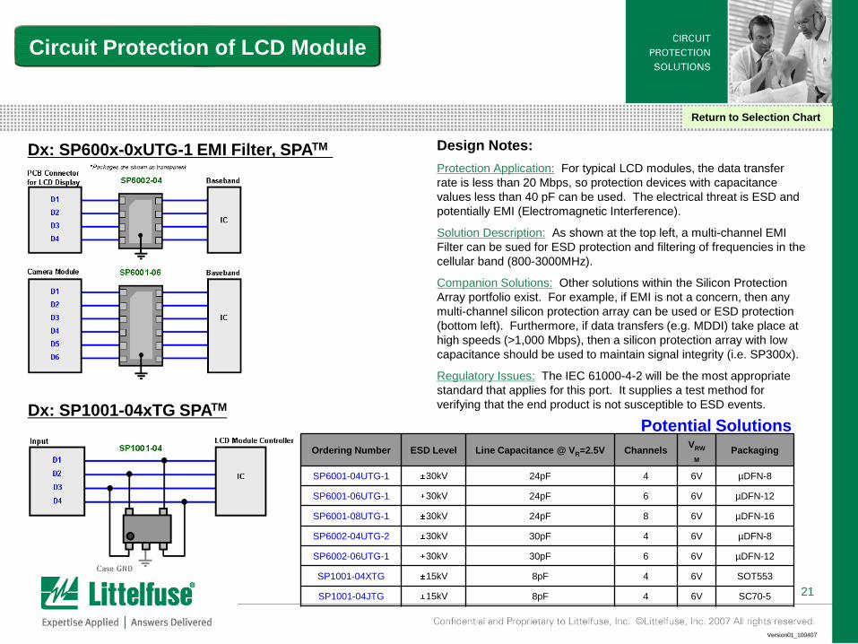
Design Notes:
Protection Application: For typical LCD modules, the data transfer
rate is less than 20 Mbps, so protection devices with capacitance
values less than 40 pF can be used. The electrical threat is ESD and
potentially EMI (Electromagnetic Interference).
Solution Description: As shown at the top left, a multi-channel EMI
Filter can be sued for ESD protection and filtering of frequencies in the
cellular band (800-3000MHz).
Companion Solutions: Other solutions within the Silicon Protection
Array portfolio exist. For example, if EMI is not a concern, then any
multi-channel silicon protection array can be used or ESD protection
(bottom left). Furthermore, if data transfers (e.g. MDDI) take place at
high speeds (>1,000 Mbps), then a silicon protection array with low
capacitance should be used to maintain signal integrity (i.e. SP300x).
Regulatory Issues: The IEC 61000-4-2 will be the most appropriate
standard that applies for this port. It supplies a test method for
verifying that the end product is not susceptible to ESD events.
Circuit Protection of LCD Module
Dx: SP600x-0xUTG-1 EMI Filter, SPATM
Dx: SP1001-04xTG SPATM
Return to Selection Chart
Ordering Number ESD Level Line Capacitance @ VR=2.5V ChannelsVRW
M
Packaging
SP6001-04UTG-1 30kV 24pF 4 6V µDFN-8
SP6001-06UTG-1 30kV 24pF 6 6V µDFN-12
SP6001-08UTG-1 30kV 24pF 8 6V µDFN-16
SP6002-04UTG-2 30kV 30pF 4 6V µDFN-8
SP6002-06UTG-1 30kV 30pF 6 6V µDFN-12
SP1001-04XTG 15kV 8pF 4 6V SOT553
SP1001-04JTG 15kV 8pF 4 6V SC70-5
Potential Solutions

22
Version01_100407
Multilayer varistor slides
Return to Selection Chart
23
Version01_100407
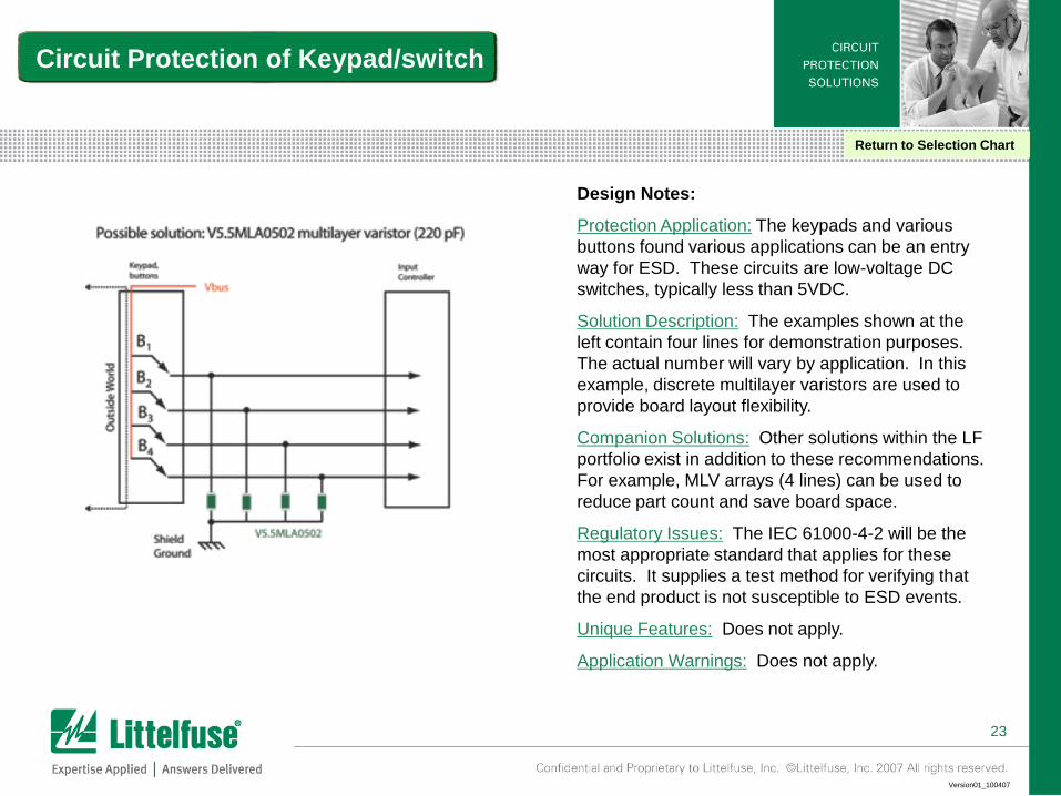
Design Notes:
Protection Application: The keypads and various
buttons found various applications can be an entry
way for ESD. These circuits are low-voltage DC
switches, typically less than 5VDC.
Solution Description: The examples shown at the
left contain four lines for demonstration purposes.
The actual number will vary by application. In this
example, discrete multilayer varistors are used to
provide board layout flexibility.
Companion Solutions: Other solutions within the LF
portfolio exist in addition to these recommendations.
For example, MLV arrays (4 lines) can be used to
reduce part count and save board space.
Regulatory Issues: The IEC 61000-4-2 will be the
most appropriate standard that applies for these
circuits. It supplies a test method for verifying that
the end product is not susceptible to ESD events.
Unique Features: Does not apply.
Application Warnings: Does not apply.
Circuit Protection of Keypad/switch
Return to Selection Chart
24
Version01_100407
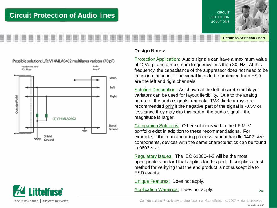
Design Notes:
Protection Application: Audio signals can have a maximum value
of 12Vp-p, and a maximum frequency less than 30kHz. At this
frequency, the capacitance of the suppressor does not need to be
taken into account. The signal lines to be protected from ESD
are the left and right channels.
Solution Description: As shown at the left, discrete multilayer
varistors can be used for layout flexibility. Due to the analog
nature of the audio signals, uni-polar TVS diode arrays are
recommended only if the negative part of the signal is -0.5V or
less since they may clip this part of the audio signal if the
magnitude is larger.
Companion Solutions: Other solutions within the LF MLV
portfolio exist in addition to these recommendations. For
example, if the manufacturing process cannot handle 0402-size
components, devices with the same characteristics can be found
in 0603-size.
Regulatory Issues: The IEC 61000-4-2 will be the most
appropriate standard that applies for this port. It supplies a test
method for verifying that the end product is not susceptible to
ESD events.
Unique Features: Does not apply.
Application Warnings: Does not apply.
Circuit Protection of Audio lines
Return to Selection Chart
25
Version01_100407
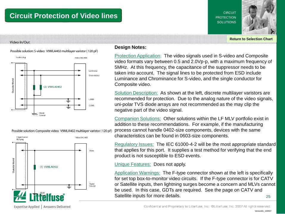
Design Notes:
Protection Application: The video signals used in S-video and Composite
video formats vary between 0.5 and 2.0Vp-p, with a maximum frequency of
5MHz. At this frequency, the capacitance of the suppressor needs to be
taken into account. The signal lines to be protected from ESD include
Luminance and Chrominance for S-video, and the single conductor for
Composite video.
Solution Description: As shown at the left, discrete multilayer varistors are
recommended for protection. Due to the analog nature of the video signals,
uni-polar TVS diode arrays are not recommended as the may clip the
negative part of the video signal.
Companion Solutions: Other solutions within the LF MLV portfolio exist in
addition to these recommendations. For example, if the manufacturing
process cannot handle 0402-size components, devices with the same
characteristics can be found in 0603-size components.
Regulatory Issues: The IEC 61000-4-2 will be the most appropriate standard
that applies for this port. It supplies a test method for verifying that the end
product is not susceptible to ESD events.
Unique Features: Does not apply.
Application Warnings: The F-type connector shown at the left is specifically
for set top box-to-monitor video circuits. If the F-type connector is for CATV
or Satellite inputs, then lightning surges become a concern and MLVs cannot
be used. In this case, GDTs are required. See the page on CATV and
Satellite inputs for more details.
Circuit Protection of Video lines
Return to Selection Chart

26
Version01_100407
Design Notes:
Protection Application: The data signals used in a USB 1.1
port vary between -0.5V to +0.5V, with a maximum data rate
of 12Mbps. At this data rate, the capacitance of the
suppressor needs to be taken into account. The signal lines
to be protected from ESD include D+ and D-. The 5VDC
power bus should be protected against ESD and overcurrent
events.
Solution Description: As shown at the left, a multilayer
varistor is used on the power bus for ESD protect, and a
PTC is used for resettable overcurrent protection. For the
data lines, discrete multilayer varistors can be used for board
layout flexibility, or to reduce part count, a single Diode array
can be used.
Companion Solutions: Other solutions within the LF portfolio
exist in addition to these recommendations. For example, if
the operating current on the power bus is higher or lower, an
appropriately rated PTC can be chosen.
Regulatory Issues: The IEC 61000-4-2 will be the most
appropriate standard that applies for this port. It supplies a
test method for verifying that the end product is not
susceptible to ESD events.
Unique Features: Does not apply.
Application Warnings: Does not apply.
Circuit Protection of USB 1.1 port
Return to Selection Chart
27
Version01_100407
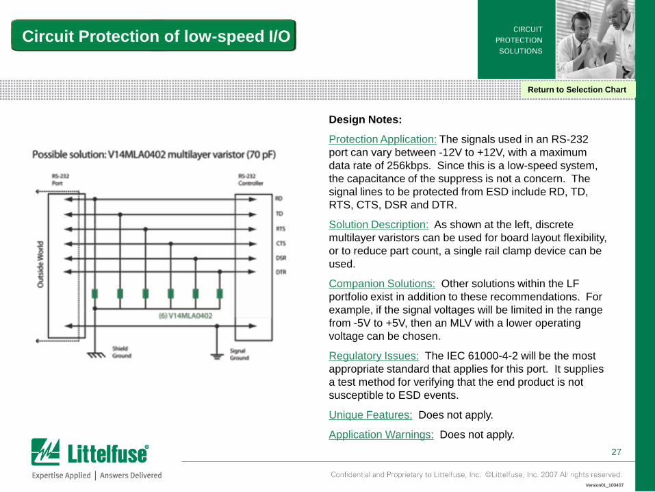
Design Notes:
Protection Application: The signals used in an RS-232
port can vary between -12V to +12V, with a maximum
data rate of 256kbps. Since this is a low-speed system,
the capacitance of the suppress is not a concern. The
signal lines to be protected from ESD include RD, TD,
RTS, CTS, DSR and DTR.
Solution Description: As shown at the left, discrete
multilayer varistors can be used for board layout flexibility,
or to reduce part count, a single rail clamp device can be
used.
Companion Solutions: Other solutions within the LF
portfolio exist in addition to these recommendations. For
example, if the signal voltages will be limited in the range
from -5V to +5V, then an MLV with a lower operating
voltage can be chosen.
Regulatory Issues: The IEC 61000-4-2 will be the most
appropriate standard that applies for this port. It supplies
a test method for verifying that the end product is not
susceptible to ESD events.
Unique Features: Does not apply.
Application Warnings: Does not apply.
Circuit Protection of low-speed I/O
Return to Selection Chart
28
Version01_100407
PulseGuard® suppressor slides
Return to Selection Chart
29
Version01_100407
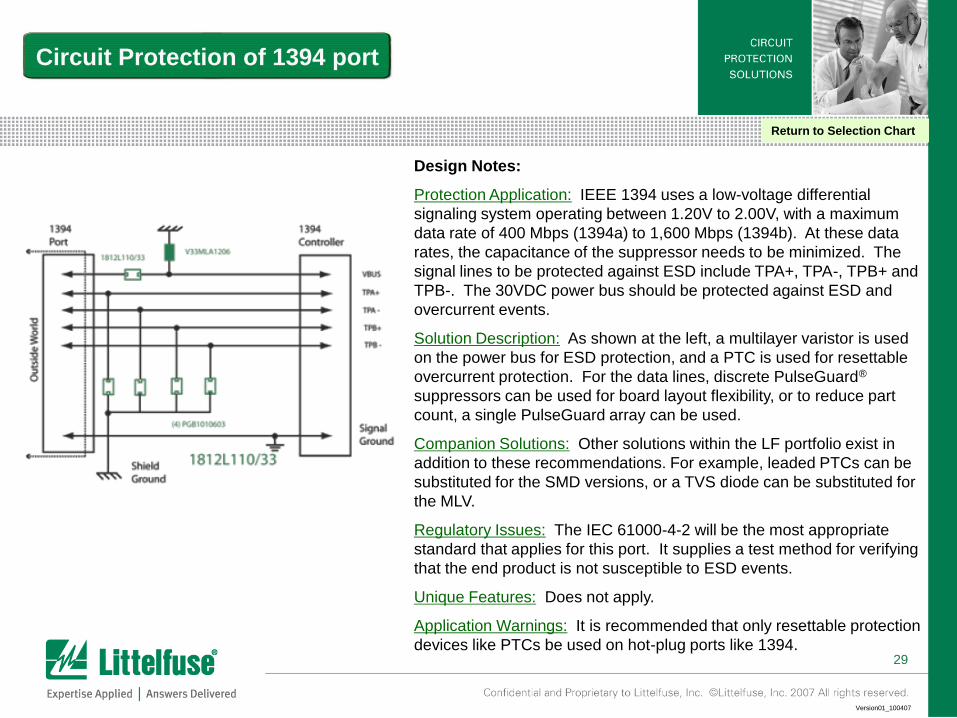
Design Notes:
Protection Application: IEEE 1394 uses a low-voltage differential
signaling system operating between 1.20V to 2.00V, with a maximum
data rate of 400 Mbps (1394a) to 1,600 Mbps (1394b). At these data
rates, the capacitance of the suppressor needs to be minimized. The
signal lines to be protected against ESD include TPA+, TPA-, TPB+ and
TPB-. The 30VDC power bus should be protected against ESD and
overcurrent events.
Solution Description: As shown at the left, a multilayer varistor is used
on the power bus for ESD protection, and a PTC is used for resettable
overcurrent protection. For the data lines, discrete PulseGuard®
suppressors can be used for board layout flexibility, or to reduce part
count, a single PulseGuard array can be used.
Companion Solutions: Other solutions within the LF portfolio exist in
addition to these recommendations. For example, leaded PTCs can be
substituted for the SMD versions, or a TVS diode can be substituted for
the MLV.
Regulatory Issues: The IEC 61000-4-2 will be the most appropriate
standard that applies for this port. It supplies a test method for verifying
that the end product is not susceptible to ESD events.
Unique Features: Does not apply.
Application Warnings: It is recommended that only resettable protection
devices like PTCs be used on hot-plug ports like 1394.
Circuit Protection of 1394 port
Return to Selection Chart
30
Version01_100407
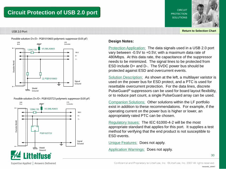
Design Notes:
Protection Application: The data signals used in a USB 2.0 port
vary between -0.5V to +0.5V, with a maximum data rate of
480Mbps. At this data rate, the capacitance of the suppressor
needs to be minimized. The signal lines to be protected from
ESD include D+ and D-. The 5VDC power bus should be
protected against ESD and overcurrent events.
Solution Description: As shown at the left, a multilayer varistor is
used on the power bus for ESD protect, and a PTC is used for
resettable overcurrent protection. For the data lines, discrete
PulseGuard® suppressors can be used for board layout flexibility,
or to reduce part count, a single PulseGuard array can be used.
Companion Solutions: Other solutions within the LF portfolio
exist in addition to these recommendations. For example, if the
operating current on the power bus is higher or lower, an
appropriately rated PTC can be chosen.
Regulatory Issues: The IEC 61000-4-2 will be the most
appropriate standard that applies for this port. It supplies a test
method for verifying that the end product is not susceptible to
ESD events.
Unique Features: Does not apply.
Application Warnings: Does not apply.
Circuit Protection of USB 2.0 port
Return to Selection Chart
31
Version01_100407
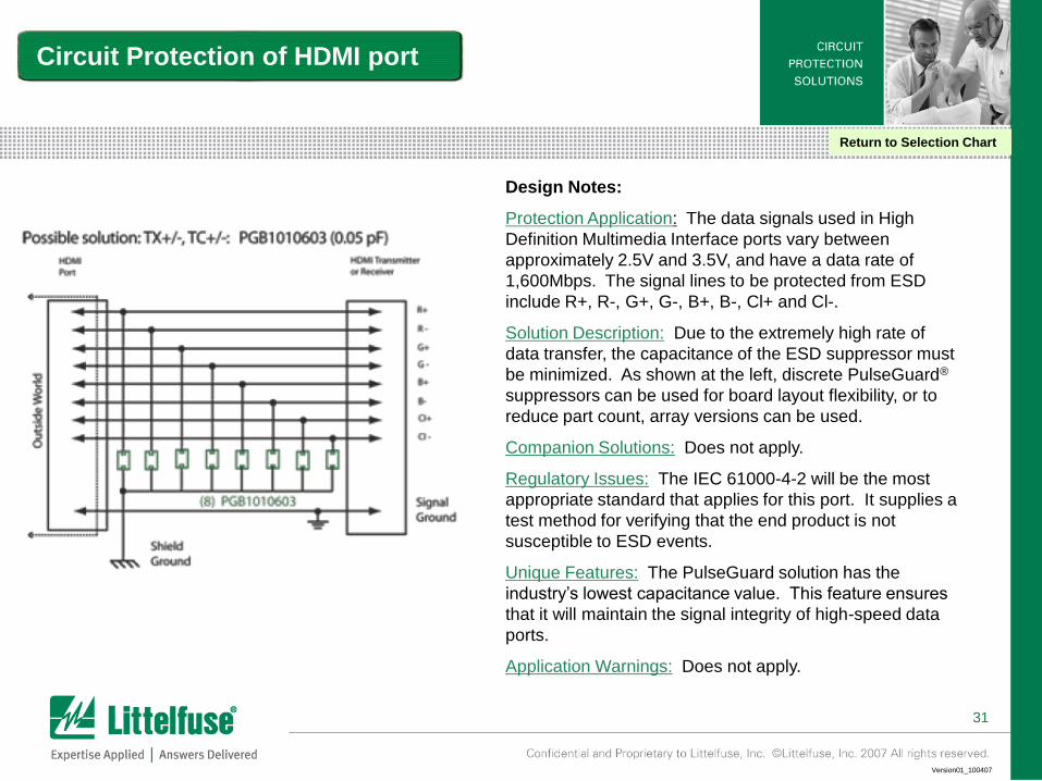
Design Notes:
Protection Application: The data signals used in High
Definition Multimedia Interface ports vary between
approximately 2.5V and 3.5V, and have a data rate of
1,600Mbps. The signal lines to be protected from ESD
include R+, R-, G+, G-, B+, B-, Cl+ and Cl-.
Solution Description: Due to the extremely high rate of
data transfer, the capacitance of the ESD suppressor must
be minimized. As shown at the left, discrete PulseGuard®
suppressors can be used for board layout flexibility, or to
reduce part count, array versions can be used.
Companion Solutions: Does not apply.
Regulatory Issues: The IEC 61000-4-2 will be the most
appropriate standard that applies for this port. It supplies a
test method for verifying that the end product is not
susceptible to ESD events.
Unique Features: The PulseGuard solution has the
industry’s lowest capacitance value. This feature ensures
that it will maintain the signal integrity of high-speed data
ports.
Application Warnings: Does not apply.
Circuit Protection of HDMI port
Return to Selection Chart
32
Version01_100407
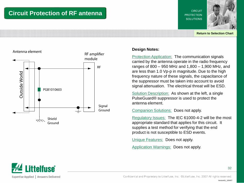
Design Notes:
Protection Application: The communication signals
carried by the antenna operate in the radio frequency
ranges of 800 – 950 MHz and 1,800 – 1,900 MHz, and
are less than 1.0 Vp-p in magnitude. Due to the high
frequency nature of these signals, the capacitance of
the suppressor must be taken into account to avoid
signal attenuation. The electrical threat will be ESD.
Solution Description: As shown at the left, a single
PulseGuard® suppressor is used to protect the
antenna element.
Companion Solutions: Does not apply.
Regulatory Issues: The IEC 61000-4-2 will be the most
appropriate standard that applies for this circuit. It
supplies a test method for verifying that the end
product is not susceptible to ESD events.
Unique Features: Does not apply.
Application Warnings: Does not apply.
Circuit Protection of RF antenna
Return to Selection Chart