esign a 3 ax 2018 release otes -...
TRANSCRIPT
DesignCAD 3D Max 2018 Release Notes
Oct 30, 2017
DesignCAD 3D Max 2018 (internal version number 27) has the following improvements.
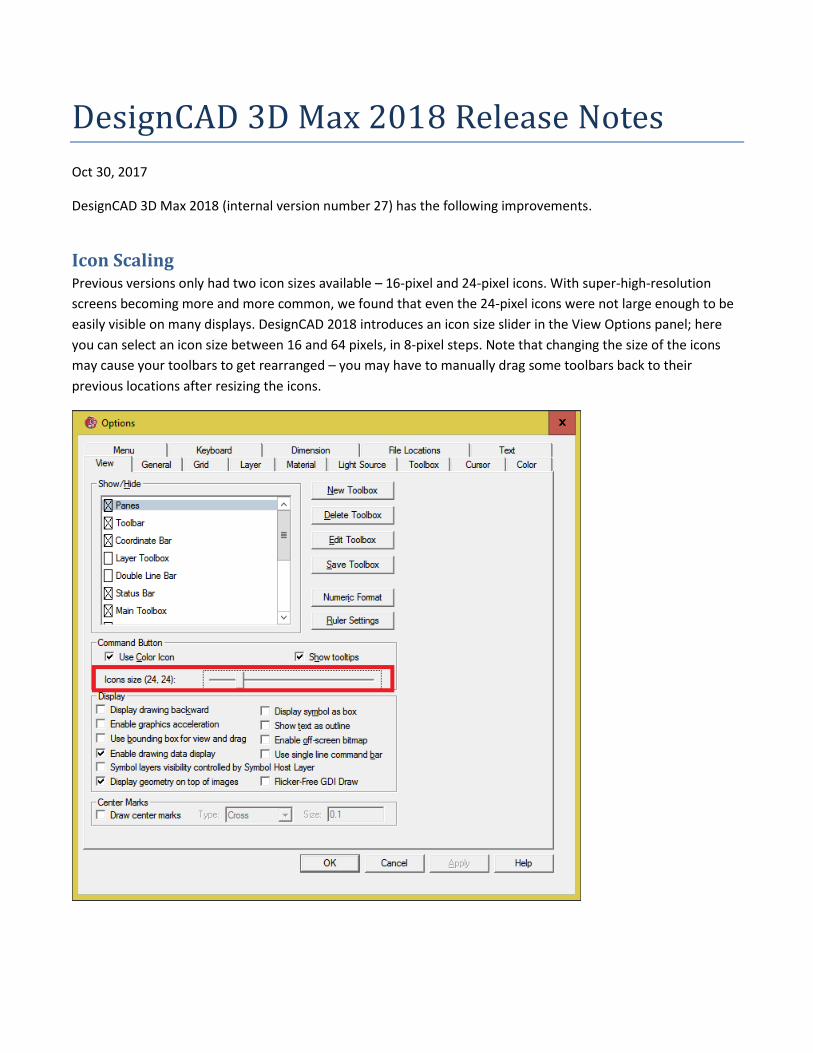
Icon Scaling Previous versions only had two icon sizes available – 16-pixel and 24-pixel icons. With super-high-resolution
screens becoming more and more common, we found that even the 24-pixel icons were not large enough to be
easily visible on many displays. DesignCAD 2018 introduces an icon size slider in the View Options panel; here
you can select an icon size between 16 and 64 pixels, in 8-pixel steps. Note that changing the size of the icons
may cause your toolbars to get rearranged – you may have to manually drag some toolbars back to their
previous locations after resizing the icons.
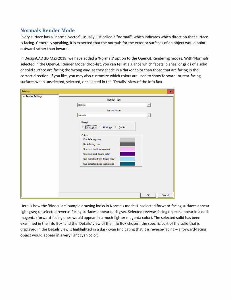
Normals Render Mode Every surface has a "normal vector", usually just called a "normal", which indicates which direction that surface
is facing. Generally speaking, it is expected that the normals for the exterior surfaces of an object would point
outward rather than inward.
In DesignCAD 3D Max 2018, we have added a 'Normals' option to the OpenGL Rendering modes. With 'Normals'
selected in the OpenGL 'Render Mode' drop-list, you can tell at a glance which facets, planes, or grids of a solid
or solid surface are facing the wrong way, as they shade in a darker color than those that are facing in the
correct direction. If you like, you may also customize which colors are used to show forward- or rear-facing
surfaces when unselected, selected, or selected in the "Details" view of the Info Box.
Here is how the 'Binoculars' sample drawing looks in Normals mode. Unselected forward-facing surfaces appear
light gray; unselected reverse-facing surfaces appear dark gray. Selected reverse-facing objects appear in a dark
magenta (forward-facing ones would appear in a much-lighter magenta color). The selected solid has been
examined in the Info Box, and the 'Details' view of the Info Box chosen; the specific part of the solid that is
displayed in the Details view is highlighted in a dark cyan (indicating that it is reverse-facing – a forward-facing
object would appear in a very light cyan color).
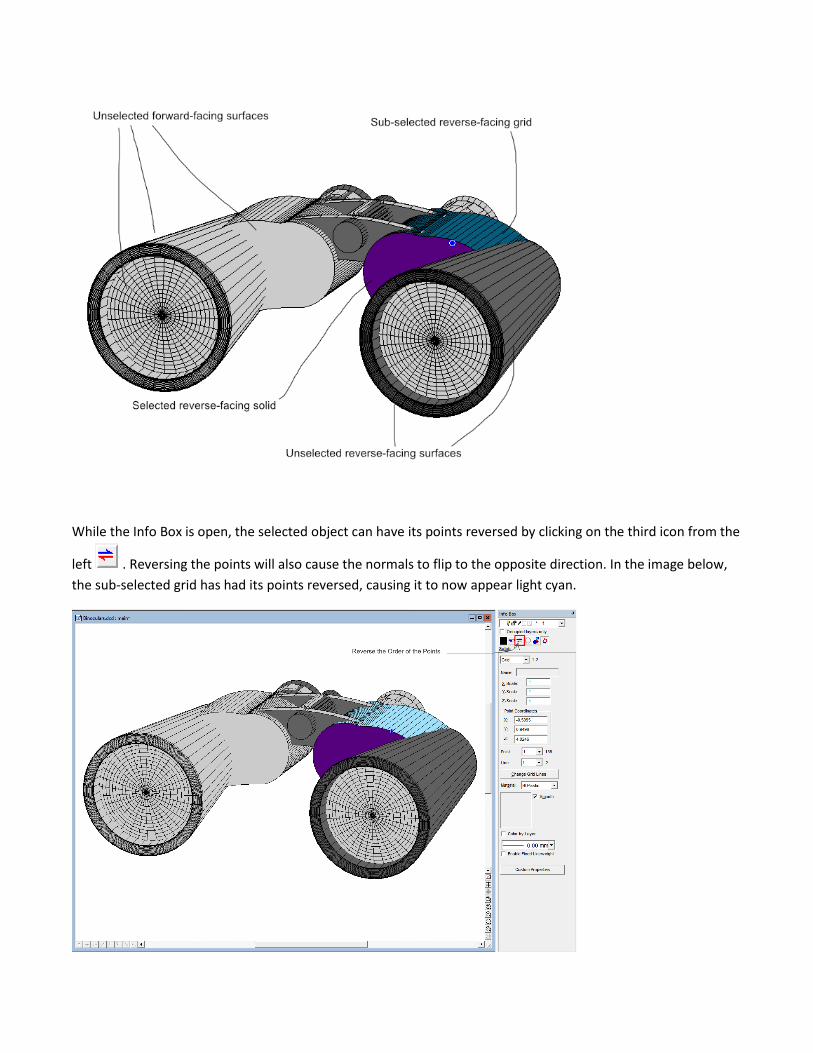
While the Info Box is open, the selected object can have its points reversed by clicking on the third icon from the
left . Reversing the points will also cause the normals to flip to the opposite direction. In the image below,
the sub-selected grid has had its points reversed, causing it to now appear light cyan.
Improvements to DesignCAD's Solid Primitives With version 2018, we have revised the algorithms so that all DesignCAD's solid primitives are created with the
surface normals consistently pointing to the outside of the solid, rather than being a mix of inward-facing and
outward-facing surfaces. This also applies to solids created with Sweep, Extrude, and Extrude Along a Curve.
New Command: Is Solid Watertight When creating 3D objects for 3D printing, it is important to know for sure whether the solid is watertight or not.
The command Edit/Selection Edit/Is Solid Watertight instructs DesignCAD to examine the selected solid and
determine if it is watertight (or 'manifold' as commonly used by 3D printing software).
The command can also be run from BasicCAD via the >IsSolidWatertight {} command.
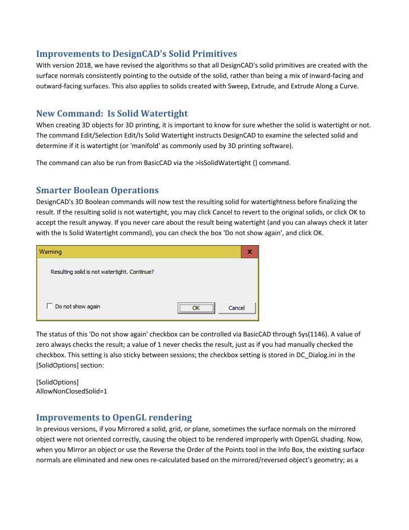
Smarter Boolean Operations DesignCAD's 3D Boolean commands will now test the resulting solid for watertightness before finalizing the
result. If the resulting solid is not watertight, you may click Cancel to revert to the original solids, or click OK to
accept the result anyway. If you never care about the result being watertight (and you can always check it later
with the Is Solid Watertight command), you can check the box 'Do not show again', and click OK.
The status of this 'Do not show again' checkbox can be controlled via BasicCAD through Sys(1146). A value of
zero always checks the result; a value of 1 never checks the result, just as if you had manually checked the
checkbox. This setting is also sticky between sessions; the checkbox setting is stored in DC_Dialog.ini in the
[SolidOptions] section:
[SolidOptions] AllowNonClosedSolid=1
Improvements to OpenGL rendering In previous versions, if you Mirrored a solid, grid, or plane, sometimes the surface normals on the mirrored
object were not oriented correctly, causing the object to be rendered improperly with OpenGL shading. Now,
when you Mirror an object or use the Reverse the Order of the Points tool in the Info Box, the existing surface
normals are eliminated and new ones re-calculated based on the mirrored/reversed object's geometry; as a
result the object now renders correctly in OpenGL. The point reversal tool can also be used to correct objects
from older drawings that were rendering incorrectly.
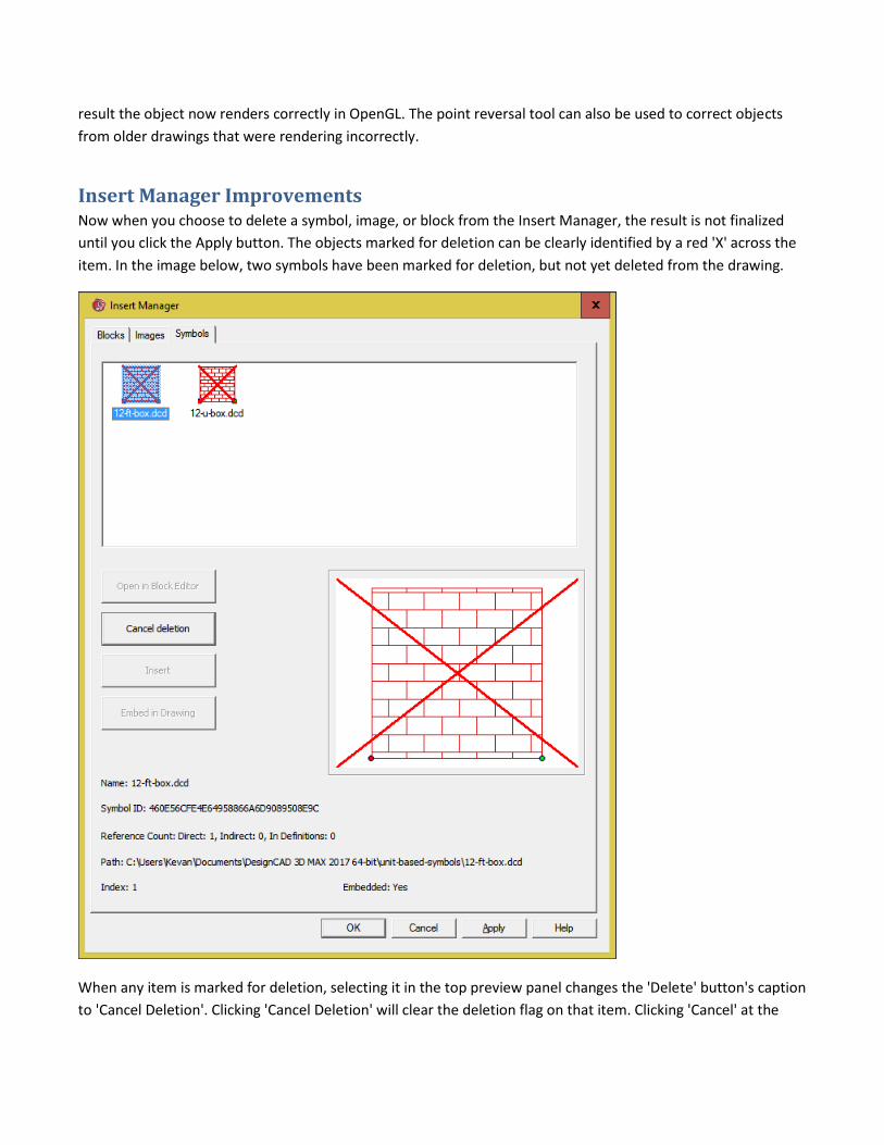
Insert Manager Improvements Now when you choose to delete a symbol, image, or block from the Insert Manager, the result is not finalized
until you click the Apply button. The objects marked for deletion can be clearly identified by a red 'X' across the
item. In the image below, two symbols have been marked for deletion, but not yet deleted from the drawing.
When any item is marked for deletion, selecting it in the top preview panel changes the 'Delete' button's caption
to 'Cancel Deletion'. Clicking 'Cancel Deletion' will clear the deletion flag on that item. Clicking 'Cancel' at the
bottom of the Insert Manager dialog will cancel all pending deletions and close the Insert Manager. Clicking
'Apply' will process all pending deletions and leave the Insert Manager open. Clicking 'OK' will process all
pending deletions and close the Insert Manager.
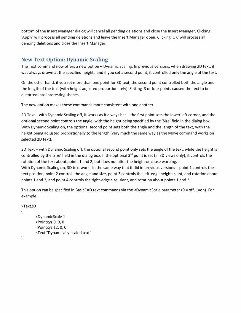
New Text Option: Dynamic Scaling The Text command now offers a new option – Dynamic Scaling. In previous versions, when drawing 2D text, it
was always drawn at the specified height, and if you set a second point, it controlled only the angle of the text.
On the other hand, if you set more than one point for 3D text, the second point controlled both the angle and
the length of the text (with height adjusted proportionately). Setting 3 or four points caused the text to be
distorted into interesting shapes.
The new option makes these commands more consistent with one another.
2D Text – with Dynamic Scaling off, it works as it always has – the first point sets the lower left corner, and the
optional second point controls the angle, with the height being specified by the 'Size' field in the dialog box.
With Dynamic Scaling on, the optional second point sets both the angle and the length of the text, with the
height being adjusted proportionally to the length (very much the same way as the Move command works on
selected 2D text).
3D Text – with Dynamic Scaling off, the optional second point only sets the angle of the text, while the height is
controlled by the 'Size' field in the dialog box. If the optional 3rd point is set (in 3D views only), it controls the
rotation of the text about points 1 and 2, but does not alter the height or cause warping.
With Dynamic Scaling on, 3D text works in the same way that it did in previous versions – point 1 controls the
text position, point 2 controls the angle and size, point 3 controls the left-edge height, slant, and rotation about
points 1 and 2, and point 4 controls the right-edge size, slant, and rotation about points 1 and 2.
This option can be specified in BasicCAD text commands via the <DynamicScale parameter (0 = off, 1=on). For
example:
>Text2D { <DynamicScale 1
<Pointxyz 0, 0, 0 <Pointxyz 12, 0, 0 <Text "Dynamically-scaled text"
}
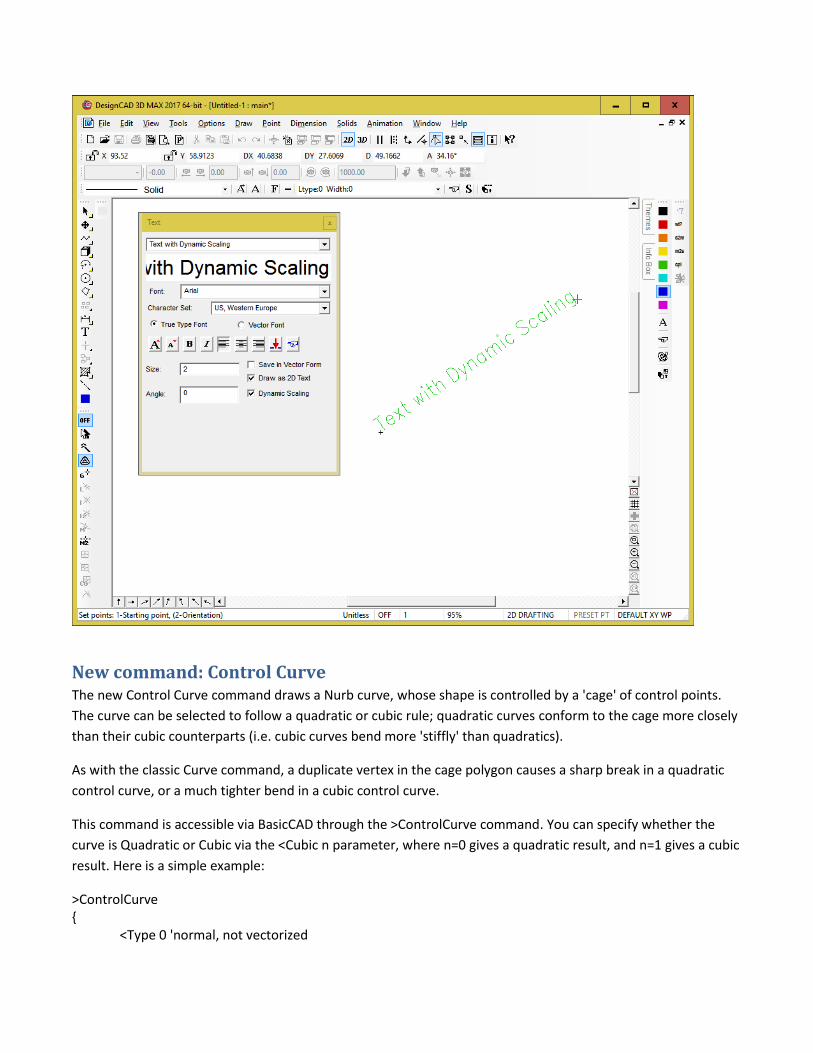
New command: Control Curve The new Control Curve command draws a Nurb curve, whose shape is controlled by a 'cage' of control points.
The curve can be selected to follow a quadratic or cubic rule; quadratic curves conform to the cage more closely
than their cubic counterparts (i.e. cubic curves bend more 'stiffly' than quadratics).
As with the classic Curve command, a duplicate vertex in the cage polygon causes a sharp break in a quadratic
control curve, or a much tighter bend in a cubic control curve.
This command is accessible via BasicCAD through the >ControlCurve command. You can specify whether the
curve is Quadratic or Cubic via the <Cubic n parameter, where n=0 gives a quadratic result, and n=1 gives a cubic
result. Here is a simple example:
>ControlCurve {
<Type 0 'normal, not vectorized
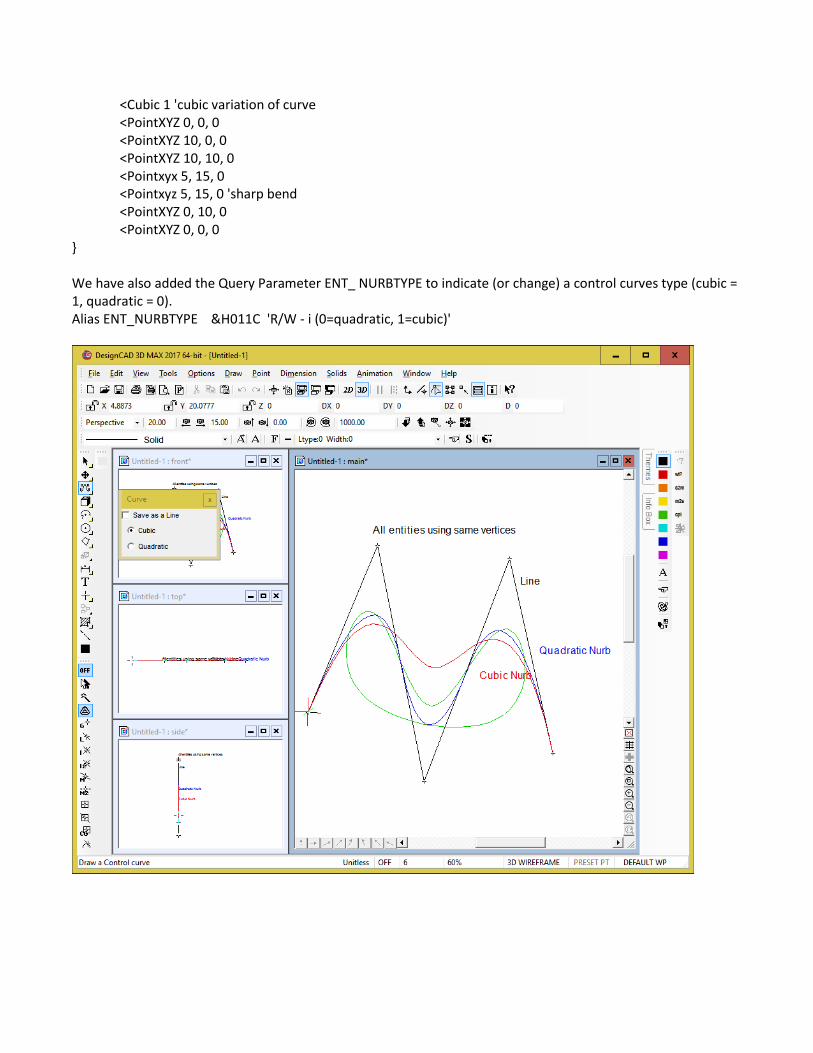
<Cubic 1 'cubic variation of curve <PointXYZ 0, 0, 0 <PointXYZ 10, 0, 0 <PointXYZ 10, 10, 0 <Pointxyx 5, 15, 0 <Pointxyz 5, 15, 0 'sharp bend <PointXYZ 0, 10, 0 <PointXYZ 0, 0, 0
} We have also added the Query Parameter ENT_ NURBTYPE to indicate (or change) a control curves type (cubic = 1, quadratic = 0). Alias ENT_NURBTYPE &H011C 'R/W - i (0=quadratic, 1=cubic)'
New Command: Solids Leak Test This command will evaluate a selected Solid Surface entity for leaks and for extra facets that prevent it from
being watertight. If it is not watertight, two new layers are added to the drawing – HoleEdges and ExtraEdges.
All edges that form holes are traced in red lines on the HoleEdges layer. All edges that form redundant facets are
traced in blue lines on the ExtraEdges layer. The underlying logic is this: in a proper closed solid, every edge
should be used by exactly two facets. If a particular edge is used in only one facet, there is a hole at that edge. If
it is used in three or more facets, there is at least one redundant facet sharing that edge. This tool is currently
incapable of detecting self-intersecting solids (such as a circle extruded along a helical path in such a way that
each revolution overlaps the previous one by some amount, or a cylinder that is partially embedded into a
cube).
This command is available in BasicCAD via the >LeakTest command.
>LeakTest { }
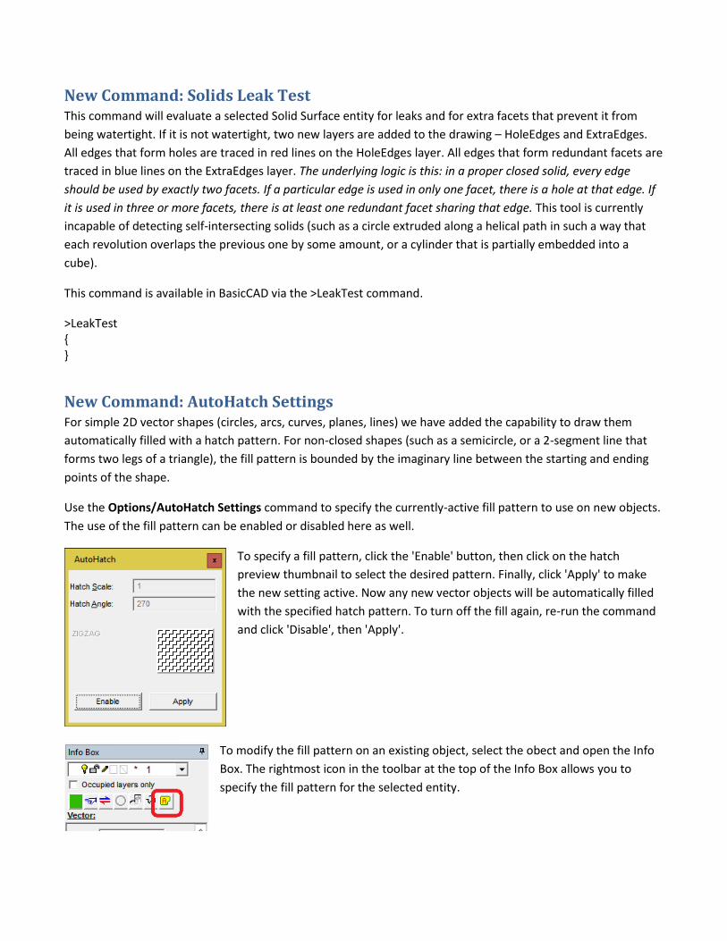
New Command: AutoHatch Settings For simple 2D vector shapes (circles, arcs, curves, planes, lines) we have added the capability to draw them
automatically filled with a hatch pattern. For non-closed shapes (such as a semicircle, or a 2-segment line that
forms two legs of a triangle), the fill pattern is bounded by the imaginary line between the starting and ending
points of the shape.
Use the Options/AutoHatch Settings command to specify the currently-active fill pattern to use on new objects.
The use of the fill pattern can be enabled or disabled here as well.
To specify a fill pattern, click the 'Enable' button, then click on the hatch
preview thumbnail to select the desired pattern. Finally, click 'Apply' to make
the new setting active. Now any new vector objects will be automatically filled
with the specified hatch pattern. To turn off the fill again, re-run the command
and click 'Disable', then 'Apply'.
To modify the fill pattern on an existing object, select the obect and open the Info
Box. The rightmost icon in the toolbar at the top of the Info Box allows you to
specify the fill pattern for the selected entity.
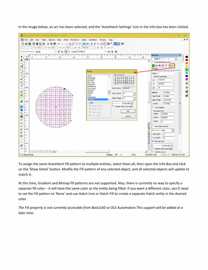
In the image below, an arc has been selected, and the 'AutoHatch Settings' icon in the Info box has been clicked.
To assign the same AutoHatch fill pattern to multiple entities, select them all, then open the Info Box and click
on the 'Show Detail' button. Modify the Fill pattern of any selected object, and all selected objects will update to
match it.
At this time, Gradient and Bitmap fill patterns are not supported. Also, there is currently no way to specify a
separate fill color – it will have the same color as the entity being filled. If you want a different color, you'll need
to set the Fill pattern to 'None' and use Hatch Line or Hatch Fill to create a separate Hatch entity in the desired
color.
The Fill property is not currently accessible from BasicCAD or OLE Automation.This support will be added at a
later time.
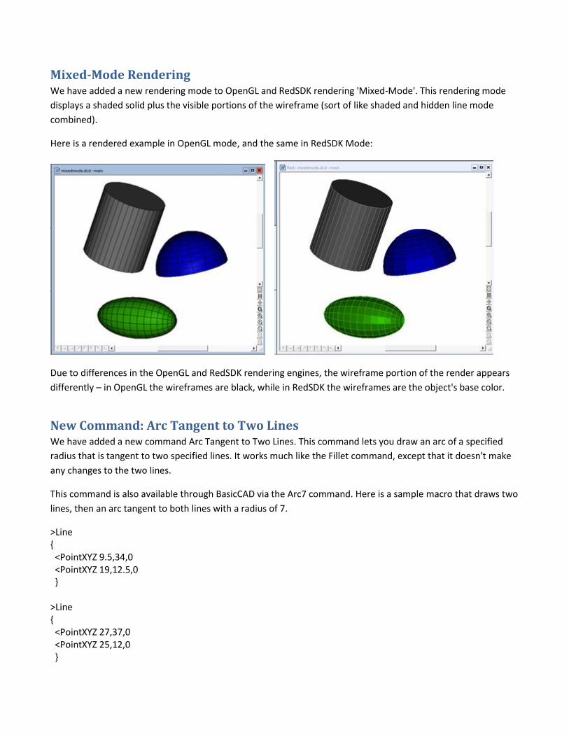
Mixed-Mode Rendering We have added a new rendering mode to OpenGL and RedSDK rendering 'Mixed-Mode'. This rendering mode
displays a shaded solid plus the visible portions of the wireframe (sort of like shaded and hidden line mode
combined).
Here is a rendered example in OpenGL mode, and the same in RedSDK Mode:
Due to differences in the OpenGL and RedSDK rendering engines, the wireframe portion of the render appears
differently – in OpenGL the wireframes are black, while in RedSDK the wireframes are the object's base color.
New Command: Arc Tangent to Two Lines We have added a new command Arc Tangent to Two Lines. This command lets you draw an arc of a specified
radius that is tangent to two specified lines. It works much like the Fillet command, except that it doesn't make
any changes to the two lines.
This command is also available through BasicCAD via the Arc7 command. Here is a sample macro that draws two
lines, then an arc tangent to both lines with a radius of 7.
>Line { <PointXYZ 9.5,34,0 <PointXYZ 19,12.5,0 } >Line { <PointXYZ 27,37,0 <PointXYZ 25,12,0 }
>Arc7 { <PointXYZ 17,16,0 <PointXYZ 26,18,0 <Radius 7 }
AutoCAD 2018 Import/Export support DesignCAD 3D Max 2018 can now import and export dwg and dxf files in AutoCAD 2018 format. Previously
attempting to Import an AutoCAD 2018 file would simply result in a 'Command failed' message, and there was
no Export option for exporting to AutoCAD 2018 format.
Other improvements: We resized the Selection Filter command's Color panel so that the RGB values of all colors can be fully
displayed; previously they would sometimes be cut off at the right end by the vertical scrollbar.
We updated the 'Save As' options to include more recent versions of DesignCAD; now you can save a
drawing from DesignCAD 2018 that is fully compatible with DesignCAD 2016, 25, 24, 21-23, 19-20, 18,
17, 16, 15, 14, 13, 12, DesignCAD 3000, DesignCAD 2000, or DesignCAD 97. If you plan to send a drawing
from the current version of DesignCAD to someone using an older version, it is always a good idea to use
Save As to save a copy of your drawing specifically for use with their version of DesignCAD; otherwise
the newer-format drawing may not load completely in their older version.
We have improved the TriangulateSurface command to automatically eliminate any degenerate
triangles (i.e. triangles with an area of zero). These triangles were a frequent source of holes in STL
exports. 3D only
We fixed a problem with Purge Unused Blocks; previously it was eliminating all symbols-by-reference
instead of checking whether they were in use or not.
We fixed a problem with the Info Box's reported scale of symbols and blocks that were created with
different units of measurement than the host drawing.
A drawing file's date and time no longer change to the current date and time after re-opening the
drawing.
When saving image files, the last-used graphics file type (bmp, png, jpg, tif, etc.) is now remembered
between sessions. This information is stored in DC_Command.ini in the lines SaveImage and
SaveImageIndex. If the two settings don't match, SaveImageIndex takes precedence.
When saving image files from the same drawing, the last-used render type (wireframe, hidden, smooth)
is remembered for as long as that drawing remains open. This information is not stored between
sessions.
Arc (Center-begin-end) – In 3D Mode, when the center, start, and end points of the arc all lie on the
same line (i.e. the arc spans 180 degrees), you can now set a fourth point to manually specify the planar
orientation of the arc.

We have added a new CutPlaneByLine macro to the Sample Macros folder. This macro cuts a pre-
selected plane along a pre-selected line. The line and plane may be selected in either order, but it is
usually easier to select the plane first, then the line. Usage: Select the plane to be cut, and the cutting
line, then use Tools/Macro Execute and select the CutPlaneByLine macro from the Sample Macros
folder. The result is two separate planes; the original plane and the cutting line are deleted as part of the
process.