essentials of pediatric endoscopic surgery
TRANSCRIPT


Essentials of Pediatric Endoscopic Surgery

Amulya K. Saxena · Michael E. Höllwarth (Eds.)
Essentials of Pediatric Endoscopic Surgery
With 701 Figures
123
ISBN 978-3-540-78386-2 e-ISBN 978-3-540-78387-9
DOI 10.1007/978-3-540-78387-9
Library of Congress Control Number: 2008924191
© Springer-Verlag Berlin Heidelberg 2009
This work is subject to copyright. All rights are reserved, wether the whole or part of the mate-rial is concerned, specifically the rights of translation, reprinting, reuse of illustrations, recitation, broadcasting, reproduction on microfilm or any other way, and storage in data banks. Duplica-tion of this publication or parts thereof is permitted only under the provisions of the German Copyright Law of September 9, 1965, in it current version, and permission for use must always be obtained from Springer. Violations are liable to prosecution under the German Copyright Law.
The use of general descriptive names, registered names, trademarks, etc. in this publication does not imply, even in the absence of a specific statement, that such names are exempt from the rele-vant protective laws and regulations and therefore free for general use.
Product liability: the publishers cannot guarantee the accuracy of any information about dosage and application contained in this book. In every individual case the user must check such infor-mation by consulting the relevant literature.
Cover illustration: Frido Steinen-Broo, eStudio Calamar, Spain
Printed on acid-free paper
9 8 7 6 5 4 3 2 1
springer.com
Amulya K. Saxena, MDAssociate ProfessorDepartment of Pediatric and Adolescent SurgeryMedical University of GrazAuenbruggerplatz 34A-8036 GrazAustria
Michael E. Höllwarth, MDProfessor and ChairDepartment of Pediatric and Adolescent SurgeryMedical University of GrazAuenbruggerplatz 34A-8036 GrazAustria

The Editors have selected a distinguished team of contributors from around the world to provide practical guidance and their expertise on various is-sues dealing with pediatric endoscopic surgery. Top-ics dealt with include theoretical concepts pertaining to endoscopic surgery, video-assisted thoracoscopic surgery, laparoscopic surgery and retroperitoneal en-doscopic procedures. Technological strides in pedi-atric endoscopic surgery have also been explained with emphasis laid on instrument refinement, evolv-ing role of ergonomics in the development of opera-tion room design, and the progress in the field of ro-botics. Constant training and evaluation of coordi-nated skills which can be estimated using virtual re-ality simulators and the capabilities of these systems have been elaborated.
Since a picture speaks more than thousand words, this monograph is designed to acquaint both the novice and the experienced surgeon with pedi-atric endoscopic procedures using surgical images and diagrams. The text is concise and emphasis has been placed on the practical and technical aspects of performing procedures. Variations in procedures have also been mentioned to offer procedural op-tions to the reader. Complications in endoscopic sur-gery arising due to limited knowledge of the instru-ment or equipment have been addressed, along with recommendations to overcome them and advice on their proper usage.
We wish to thank all the authors for their out-standing contributions and for offering their valu-able experience in pediatric endoscopic surgery to-wards this compilation. We express our gratitude
General pediatric surgery has undergone a revo-lutionary change in the last decade, with the wide-spread acceptance and adoption of endoscopic sur-gery in the neonatal, pediatric and adolescent age groups. The establishment of pediatric endoscopic surgery was due to the combined efforts of dedi-cated pediatric surgeons who devoted precious time in implementing, evaluating, innovating and adapt-ing procedures for the pediatric age group, manufac-tures who invested into research and development of pediatric instruments and equipments despite being aware of the relatively small market share in pediatric surgery and the establishment of an international fo-rum to exchange and compare experiences as well as support advances and promote research.
Pediatric endoscopic surgery requires the knowl-edge of and familiarity of existing equipment with the ability to constantly adapt to ongoing innova-tions. The perception of the three-dimensional op-eration field in two-dimension requires good hand-eye coordination and hours of practice to familiar-ize with the basic procedures while acquiring skills for advanced procedures. The spectrum of patients treated using pediatric endoscopic surgical proce-dures ranges from premature infants to adolescents, which adds another dimension to the technical com-plexity in terms of extreme variations in size encoun-tered by pediatric surgeons. Techniques in endo-scopic surgery might be new initially and may require additional training to accomplish, however the surgi-cal goal remains the same as in open procedures. As these techniques become standard practice, the ease to perform endoscopic procedures will increase.
Preface

VI Preface
to Reiner Klostermann (Product Manager, Richard Wolf GmbH, Germany) for his continued assistance throughout the project. We also appreciate the assis-tance from our industry partners who have contrib-uted generously toward this work. Finally, we wish to thank the editorial staff of Springer, Stephanie Benko and Gabriele Schroeder, for the excellent assistance during the entire publication process.
We hope that this work contributes to the better understanding of pediatric endoscopic surgery and benefits children throughout the world.
Amulya K. Saxena, MDMichael E. Höllwarth, MD

2 Instrumentation and Equipment 17
Amulya K. Saxena2.1 Port and Trocar . . . . . . . . . . . . . . . . . . . 17
2.2 Veress Needle . . . . . . . . . . . . . . . . . . . . . 18
2.3 Blunt Grasping Forceps . . . . . . . . . . . 18
2.4 Dissectors and Tissue Extractors 19
2.5 Biopsy Forceps . . . . . . . . . . . . . . . . . . . . 20
2.6 Endoscopic Retractor Instruments 20
2.7 Needle Holders . . . . . . . . . . . . . . . . . . . 21
2.8 Knot Pushers . . . . . . . . . . . . . . . . . . . . . . 21
2.9 Probes . . . . . . . . . . . . . . . . . . . . . . . . . . . . 22
2.10 Goldfinger® Dissector . . . . . . . . . . . . . 22
2.11 Endoscopic Clip Applicators . . . . . . 23
2.12 Endoscopic Linear Stapler . . . . . . . . 23
2.13 Circular Intraluminal Anastomosis Stapler . . . . . . . . . . . . . . 24
2.14 Specimen Retrieval Bags . . . . . . . . . . 24
2.15 Endoscopic Loop Suture . . . . . . . . . . 25
2.16 Automated Laparoscope Assistance . . . . . . . . . . . . . . . . . . . . . . . . . 25
2.17 Electrosurgery Devices . . . . . . . . . . . 26
2.17.1 Coagulation and Dissection . . . . . . . 26
2.17.2 Monopolar Coagulation . . . . . . . . . . . 26
2.17.3 Bipolar Coagulation . . . . . . . . . . . . . . 27
2.17.4 Harmonic Technology/Instruments . . . . . . . . . . . . . . . . . . . . . . . 27
2.17.5 LigaSure™ Sealing Device . . . . . . . . . 28
2.18 Laser Fiber Optics . . . . . . . . . . . . . . . . 28
2.18.1 Scopes and Video Camera Systems 29
2.19 Light Sources . . . . . . . . . . . . . . . . . . . . . 32
2.19.1 Light-Source Generators and Transmission Pathways . . . . . . . 32
Section 1
Concepts in Endoscopic Surgery . . . . . . . . . . 1
1 History of Endoscopic Surgery . . 3
Amulya K. Saxena1.1 Giulio Cesare Aranzi . . . . . . . . . . . . . . 3
1.2 Origin of Trocar . . . . . . . . . . . . . . . . . . 4
1.3 Philip Bozzini . . . . . . . . . . . . . . . . . . . . . 4
1.3.1 Bozzini’s “Lichtleiter” . . . . . . . . . . . . . 5
1.4 Antoine Jean Desormeaux . . . . . . . . 5
1.4.1 Desormeaux’s “Endoscope” . . . . . . . . 6
1.5 Adolf Kussmaul . . . . . . . . . . . . . . . . . . . 6
1.6 Maximillian Carl-Friedrich Nitze 7
1.7 Thomas Alva Edison . . . . . . . . . . . . . . 7
1.8 Johannes Freiherr von Mikulicz-Radecki . . . . . . . . . . . . . 8
1.9 Georg Kelling . . . . . . . . . . . . . . . . . . . . . 8
1.10 Hans Christian Jacobaeus . . . . . . . . . 9
1.11 Bertram Moses Bernheim . . . . . . . . . 9
1.12 Severin Nordentoft . . . . . . . . . . . . . . . 10
1.13 Heinz Kalk . . . . . . . . . . . . . . . . . . . . . . . . 10
1.14 John Carroll Ruddock . . . . . . . . . . . . . 11
1.15 János Veres . . . . . . . . . . . . . . . . . . . . . . . . 11
1.16 Raoul Palmer . . . . . . . . . . . . . . . . . . . . . 12
1.17 Harold Horace Hopkins . . . . . . . . . . . 12
1.18 Kurt Karl Stephan Semm . . . . . . . . . . 13
1.19 Harrith Hasson . . . . . . . . . . . . . . . . . . . 13
1.20 Erich Mühe . . . . . . . . . . . . . . . . . . . . . . . 14
1.21 Philippe Mouret . . . . . . . . . . . . . . . . . . 14
1.22 Michael Harrison . . . . . . . . . . . . . . . . . 15
Contents

VIII Contents
2.19.2 Fiber-Optic Cables for Light Transmission . . . . . . . . . . . . 33
2.19.3 The Concept of White Balancing 34
2.20 Insufflation, Irrigation and Aspiration Devices . . . . . . . . . . . 34
2.20.1 Insufflation Devices . . . . . . . . . . . . . . 34
2.20.2 Concepts in Irrigation and Aspiration . . . . . . . . . . . . . . . . . . . . 35
2.20.3 Instruments for Irrigation and Aspiration . . . . . . . . . . . . . . . . . . . . 35
2.21 Video and Data Storage Equipment . . . . . . . . . . . . . . . . . . . . . . . 36
2.21.1 Digital Video Recorders . . . . . . . . . . 36
2.21.2 Digital Video Printers . . . . . . . . . . . . 36
2.21.3 Digital Video Managers . . . . . . . . . . . 37
2.21.4 Flat-Panel Screens . . . . . . . . . . . . . . . . 37
2.21.5 Endoscopic Surgery Towers . . . . . . . 38
2.22 Trainers for Endoscopic Surgery . . 38
2.22.1 Pelvitrainers . . . . . . . . . . . . . . . . . . . . . . 38
2.22.2 Virtual Reality Simulators . . . . . . . . 39
3 Ergonomics of Endoscopic Surgery . . . . . . . . . . . 41
Steven Z. Rubin and Marcos Bettolli
3.1 Introduction . . . . . . . . . . . . . . . . . . . . . . 41
3.1.1 Indications for Endoscopic Surgery . . . . . . . . . . . . . . . . . . . . . . . . . . . 41
3.1.2 Requirement for Procedures . . . . . . 41
3.1.3 Complications . . . . . . . . . . . . . . . . . . . . 41
3.2 Definition and Aim . . . . . . . . . . . . . . . 41
3.3 Operating Room Requirements . . . 41
3.4 Manpower Requirements . . . . . . . . . 41
3.5 Technical Requirements . . . . . . . . . . 42
3.6 Robotics . . . . . . . . . . . . . . . . . . . . . . . . . . 43
3.7 Improvement of Team Performance . . . . . . . . . . . . . 43
3.8 The Future . . . . . . . . . . . . . . . . . . . . . . . . 43
3.9 Operating Staff Positions and Ergonomics . . . . . . . . . . . . . . . . . . . 44
3.9.1 Single-Monitor Option . . . . . . . . . . . 44
3.9.2 Dual-Monitor Option . . . . . . . . . . . . . 45
3.9.3 Ventilator vs. Monitor Placement 46
4 Instrument Ergonomics . . . . . . . . . . 47
Amulya K. Saxena4.1 Endoscopic Surgery and Surgeons 47
4.2 Ergonomics and Instruments . . . . . 47
4.2.1 Paradoxical Port Movement . . . . . . . 47
4.2.2 Working Field Perimeters . . . . . . . . . 48
4.2.3 Instrument Cluttering . . . . . . . . . . . . 48
4.2.4 Working Angles . . . . . . . . . . . . . . . . . . . 49
4.2.5 Handle Design . . . . . . . . . . . . . . . . . . . . 49
4.2.6 Power Grip and Precision . . . . . . . . . 49
4.2.7 Hand and Wrist Movements . . . . . . 49
4.2.8 Adaptation for Various Hand Sizes 49
4.2.9 Buttons and Springs . . . . . . . . . . . . . . . 50
4.2.10 Multifunctionality of Handles . . . . 50
5 Suturing Techniques . . . . . . . . . . . . . 51
Lutz Stroedter5.1 Endoscopic Suturing . . . . . . . . . . . . . . 51
5.2 Parameters Influencing Intracorporeal Suturing . . . . . . . . . . . 51
5.3 Endoscopic Needle Shapes . . . . . . . . 51
5.4 Endoscopic Suture Materials . . . . . . 52
5.4.1 Ski Needle . . . . . . . . . . . . . . . . . . . . . . . . 52
5.4.2 Extracorporeal Knot Tying . . . . . . . . 53
5.4.3 Intracorporeal Knot Tying . . . . . . . . 55
6 Effects of Insufflation . . . . . . . . . . . . 59
Amulya K. Saxena6.1 Insufflating Gas Properties . . . . . . . 59
6.2 Gas Delivery Systems . . . . . . . . . . . . . 59
6.3 The Jewel-Thompson Effect . . . . . . 59
Contents IX
6.4 Insufflation Flow Values . . . . . . . . . . 59
6.5 Water Content of Gases . . . . . . . . . . . 60
6.6 Insufflation Pressures . . . . . . . . . . . . . 60
6.7 Dynamic Condition . . . . . . . . . . . . . . . 60
6.8 Stress/Immunologic Responses . . . 60
6.9 Physiological Changes From CO₂ 60
6.10 Cardiopulmonary Effects . . . . . . . . . 60
6.11 Combustion Under Low Oxygen Content . . . . . . . . . . . . . . . . . . . . . . . . . . . 61
6.12 Venous Blood Return . . . . . . . . . . . . . 61
6.13 Methemoglobinemia . . . . . . . . . . . . . . 61
6.14 Intra-abdominal Organ Perfusion 61
6.15 CO₂ Elimination After the Procedure . . . . . . . . . . . . . . . 62
6.16 Shoulder Pain after CO₂ Insufflation . . . . . . . . . . . . . . . . . . . . . . . 62
7 Anesthesia Considerations . . . . . . 63
Anton Gutmann7.1 Preoperative Evaluation . . . . . . . . . . . 63
7.2 Premedication . . . . . . . . . . . . . . . . . . . . 63
7.3 Induction of Anesthesia . . . . . . . . . . 63
7.4 Muscle Relaxants and Analgesics 63
7.5 Decompression . . . . . . . . . . . . . . . . . . . 64
7.6 Intraoperative Monitoring . . . . . . . . 64
7.7 Intraoperative Cardiovascular Complications . . . . . . . . . . . . . . . . . . . . 64
7.7.1 Venous Gas Embolus . . . . . . . . . . . . . . 64
7.7.2 Hypotension . . . . . . . . . . . . . . . . . . . . . . 64
7.7.3 Hypertension . . . . . . . . . . . . . . . . . . . . . 65
7.7.4 Dysrhythmias . . . . . . . . . . . . . . . . . . . . . 65
7.8 Intraoperative Pulmonary Complications . . . . . . . . . . . . . . . . . . . . 65
7.8.1 Hypoxia . . . . . . . . . . . . . . . . . . . . . . . . . . . 65
7.8.2 Hypercarbia . . . . . . . . . . . . . . . . . . . . . . . 65
7.9 Postoperative Management . . . . . . . 65
7.9.1 Patient Care . . . . . . . . . . . . . . . . . . . . . . . 65
7.9.2 Pain Management . . . . . . . . . . . . . . . . . 65
8 Preoperative Considerations . . . . 67
Amulya K. Saxena8.1 Explanation of Procedures . . . . . . . . 67
8.2 Surgical Team Coordination . . . . . . 67
8.3 Operating Room Set Up . . . . . . . . . . 67
8.4 Instrumentation and Equipment . . 67
8.5 Patient Preparation . . . . . . . . . . . . . . . 68
8.6 Patient Safety Concerns . . . . . . . . . . . 68
8.7 Video and Documentation Systems . . . . . . . . . . . . . . . . . . . . . . . . . . . 68
8.8 Fogging of Endoscopes . . . . . . . . . . . 68
8.9 Endoscopes . . . . . . . . . . . . . . . . . . . . . . . 68
8.10 Compatibility of Accessories . . . . . . 68
8.11 Lasers in Endoscopic Surgery . . . . . 69
8.12 Preparation and Draping . . . . . . . . . . 69
9 Closed- and Open-Access Techniques . . . . . . . . . 71
Johannes Schalamon9.1 Assortment and Definition
of Ports . . . . . . . . . . . . . . . . . . . . . . . . . . . 71
9.2 Main Access Techniques . . . . . . . . . . 71
9.3 Umbilical Access Sites . . . . . . . . . . . . 71
9.4 Trocar and Veress Needle Injuries 71
9.5 Veress Needle Insertion . . . . . . . . . . . 72
9.6 Removal of the Ports . . . . . . . . . . . . . . 72
9.7 Closed Abdominal Access Using a Veress Needle . . . . . . . . . . . . . . . . . . . 72
9.8 Open Abdominal Access . . . . . . . . . . 74
10 Concepts in Video-Assisted Thoracic Surgery (VATS) . . . . . . . . 77
Stephanie P. Acierno and John H.T. Waldhausen
10.1 Introduction to Video-Assisted Thoracic Surgery . . . . . . . . . . . . . . . . . . 77
10.2 Indications for VATS . . . . . . . . . . . . . . 78
10.3 Contraindications . . . . . . . . . . . . . . . . . 79

X Contents
10.3.1 Absolute Contraindications . . . . . . . 79
10.3.2 Relative Contraindications . . . . . . . . 79
10.4 Anesthesia Considerations . . . . . . . . 79
10.4.1 Preoperative Considerations . . . . . . 79
10.4.2 Double-Lung Ventilation Option 79
10.4.3 Single-Lung Ventilation Option – I . . . . . . . . . . . . . . . . . . . . . . . . . 80
10.4.4 Single-Lung Ventilation Option – II . . . . . . . . . . . . . . . . . . . . . . . . 80
10.4.5 Single-Lung Ventilation Option – III . . . . . . . . . . . . . . . . . . . . . . . 80
10.5 Technical Considerations for VATS . . . . . . . . . . . . . . . . . . . . . . . . . . 81
10.5.1 Preoperative Imaging . . . . . . . . . . . . . 81
10.5.2 Positioning of the Patient . . . . . . . . . 81
10.5.3 Access to Mediastinal Lesions . . . . 82
10.5.4 Access to the Diaphragm . . . . . . . . . 82
10.6 Basic Instrumentation . . . . . . . . . . . . 83
10.7 Use of a Chest Tube Postoperatively . . . . . . . . . . . . . . . . . . . . 85
10.8 Complications of VATS . . . . . . . . . . . 85
11 Robot-Assisted Pediatric Surgery 87
Venita Chandra, Sanjeev Dutta and Craig T. Albanese
11.1 Introduction . . . . . . . . . . . . . . . . . . . . . . 87
11.2 The Surgical Robotic System . . . . . . 87
11.3 Advantages of Robotics in Children . . . . . . . . . . . . . . . . . . . . . . . 88
11.4 Disadvantages of Robotics in Children . . . . . . . . . . . . . . . . . . . . . . . 88
11.5 Anesthetic Considerations . . . . . . . . 88
11.6 Preoperative Considerations . . . . . . 89
11.7 Current Applications in Pediatric Subspecialties . . . . . . . . . . . . . . . . . . . . . 89
11.8 Clinical Utility in Pediatric Surgery . . . . . . . . . . . . . . . 89
11.9 Future of Robotic Surgery . . . . . . . . 89
11.10 Current Applications in Pediatric General Surgery . . . . . . . . . . . . . . . . . . 90
11.11 Conclusion . . . . . . . . . . . . . . . . . . . . . . . 90
Section 2
Video-Assisted Thoracoscopic Surgery (VATS) . . . . . . . . . . . . . 91
12 Lobectomy . . . . . . . . . . . . . . . . . . . . . . . 93
Steven S. Rothenberg12.1 Operation Room Setup . . . . . . . . . . 93
12.2 Patient Positioning . . . . . . . . . . . . . . . 94
12.3 Special Instruments . . . . . . . . . . . . . . 94
12.4 Location of Access Points . . . . . . . . 94
12.5 Indications . . . . . . . . . . . . . . . . . . . . . . . 95
12.6 Contraindications . . . . . . . . . . . . . . . . 95
12.7 Preoperative Considerations . . . . . 95
12.8 Technical Notes . . . . . . . . . . . . . . . . . . 95
12.9 Procedure Variations . . . . . . . . . . . . . 95
12.10 Thoracoscopic Lobectomy Procedure . . . . . . . . . . . . . . . . . . . . . . . . 95
13 Bronchogenic Cyst Resection . . . 99
Roshni Dasgupta and Richard G. Azizkhan
13.1 Operation Room Setup . . . . . . . . . . 99
13.2 Patient Positioning . . . . . . . . . . . . . . . 100
13.3 Special Instruments . . . . . . . . . . . . . . 100
13.4 Location of Access Points . . . . . . . . 100
13.5 Indications . . . . . . . . . . . . . . . . . . . . . . . 101
13.6 Preoperative Considerations . . . . . 101
13.7 Technical Notes . . . . . . . . . . . . . . . . . . 101
13.8 Procedure Variations . . . . . . . . . . . . . 101
13.9 Thoracoscopic Resection of Bronchogenic Cysts . . . . . . . . . . . 101

Contents XI
14 Resection of Pulmonary Sequestrations . . . . . . . . . . . . . . . . . . 105
Lutz Stroedter14.1 Operation Room Setup . . . . . . . . . . 105
14.2 Patient Positioning . . . . . . . . . . . . . . . 106
14.3 Special Instruments . . . . . . . . . . . . . . 106
14.4 Location of Access Points . . . . . . . . 106
14.5 Indications . . . . . . . . . . . . . . . . . . . . . . . 107
14.6 Contraindications . . . . . . . . . . . . . . . . 107
14.7 Preoperative Considerations . . . . . 107
14.8 Technical Notes . . . . . . . . . . . . . . . . . . 107
14.9 Procedure Variations . . . . . . . . . . . . . 107
14.10 Thoracoscopic Resection of Intralobar Sequestrations . . . . . 107
15 Treatment of Pulmonary Blebs and Bullae . . . . . . . . . . . . . . . . 111
Amulya K. Saxena15.1 Operation Room Setup . . . . . . . . . . 111
15.2 Patient Positioning . . . . . . . . . . . . . . . 112
15.3 Special Instruments . . . . . . . . . . . . . . 112
15.4 Location of Access Points . . . . . . . . 112
15.5 Indications . . . . . . . . . . . . . . . . . . . . . . . 113
15.6 Contraindications . . . . . . . . . . . . . . . . 113
15.7 Preoperative Considerations . . . . . 113
15.8 Technical Notes . . . . . . . . . . . . . . . . . . 113
15.9 Procedure Variations . . . . . . . . . . . . . 113
15.10 Thoracoscopic Options for Pulmonary Blebs and Bullae 113
16 Thoracic Neuroblastoma Resection . . . . . . . 117
Michael E. Höllwarth16.1 Operation Room Setup . . . . . . . . . . 117
16.2 Patient Positioning . . . . . . . . . . . . . . . 118
16.3 Special Instruments . . . . . . . . . . . . . . 118
16.4 Location of Access Points . . . . . . . . 118
16.5 Indications . . . . . . . . . . . . . . . . . . . . . . . 119
16.6 Contraindications . . . . . . . . . . . . . . . . 119
16.7 Preoperative Considerations . . . . . 119
16.8 Technical Notes . . . . . . . . . . . . . . . . . . 119
16.9 Procedure Variations . . . . . . . . . . . . . 119
16.10 Thoracoscopic Resection of Neuroblastoma . . . . . . . . . . . . . . . . 119
17 Esophageal Atresia Repair . . . . . . 123
Klaas N.M.A. Bax and David C. van der Zee
17.1 Operation Room Setup . . . . . . . . . . 123
17.2 Patient Positioning . . . . . . . . . . . . . . . 124
17.3 Special Instruments . . . . . . . . . . . . . . 124
17.4 Location of Access Points . . . . . . . . 124
17.5 Indications . . . . . . . . . . . . . . . . . . . . . . . 125
17.6 Contraindications . . . . . . . . . . . . . . . . 125
17.7 Preoperative Considerations . . . . . 125
17.8 Technical Notes . . . . . . . . . . . . . . . . . . 125
17.9 Instrumentation . . . . . . . . . . . . . . . . . 125
17.10 Thoracoscopic Esophageal Atresia Repair . . . . . . . . . . . . . . . . . . . . . . . . . . . . 125
18 Congenital Diaphragmatic Hernia Repair . . . . . . . . . . . . . . . . . . . 129
François Becmeur18.1 Operation Room Setup . . . . . . . . . . 129
18.2 Patient Positioning . . . . . . . . . . . . . . . 130
18.3 Special Instruments . . . . . . . . . . . . . . 130
18.4 Location of Access Points . . . . . . . . 130
18.5 Indications . . . . . . . . . . . . . . . . . . . . . . . 131
18.6 Contraindications . . . . . . . . . . . . . . . . 131
18.7 Preoperative Considerations . . . . . 131
18.8 Technical Notes . . . . . . . . . . . . . . . . . . 131
18.9 Procedure Variations . . . . . . . . . . . . . 131
18.10 Thoracoscopic Congenital Diaphragmatic Hernia Repair . . . . 131
XII Contents
19 Thymectomy . . . . . . . . . . . . . . . . . . . . 137
Michael E. Höllwarth19.1 Operation Room Setup . . . . . . . . . . 137
19.2 Patient Positioning . . . . . . . . . . . . . . . 138
19.3 Special Instruments . . . . . . . . . . . . . . 138
19.4 Location of Access Points . . . . . . . . 138
19.5 Indications . . . . . . . . . . . . . . . . . . . . . . . 139
19.6 Contraindications . . . . . . . . . . . . . . . . 139
19.7 Preoperative Considerations . . . . . 139
19.8 Technical Notes . . . . . . . . . . . . . . . . . . 139
19.9 Procedure Variations . . . . . . . . . . . . . 139
19.10 Thoracoscopic Thymectomy . . . . . 139
20 Aortopexy . . . . . . . . . . . . . . . . . . . . . . . 143
Timothy D. Kane20.1 Operation Room Setup . . . . . . . . . . 143
20.2 Patient Positioning . . . . . . . . . . . . . . . 144
20.3 Special Instruments . . . . . . . . . . . . . . 144
20.4 Location of Access Points . . . . . . . . 144
20.5 Indications . . . . . . . . . . . . . . . . . . . . . . . 145
20.6 Contraindications . . . . . . . . . . . . . . . . 145
20.7 Preoperative Considerations . . . . . 145
20.8 Technical Notes . . . . . . . . . . . . . . . . . . 145
20.9 Procedure Variations . . . . . . . . . . . . . 145
20.10 Right Thoracoscopic Aortopexy for Tracheomalacia . . . . . . . . . . . . . . 145
21 Closure of a Patent Ductus Arteriosus . . . . . . . 149
Kari Vanamo21.1 Operation Room Setup . . . . . . . . . . 149
21.2 Patient Positioning . . . . . . . . . . . . . . . 150
21.3 Special Instruments . . . . . . . . . . . . . . 150
21.4 Location of Access Points . . . . . . . . 150
21.5 Indications . . . . . . . . . . . . . . . . . . . . . . . 151
21.6 Contraindications . . . . . . . . . . . . . . . . 151
21.7 Preoperative Considerations . . . . . 151
21.8 Technical Notes . . . . . . . . . . . . . . . . . . 151
21.9 Procedure Variations . . . . . . . . . . . . . 151
21.10 Thoracoscopic Closure of a Patent Ductus Arteriosus . . . . 151
22 Endoscopic Transthoracic Sympathectomy . . . . . . . . . . . . . . . . . 155
Sergey Keidar and Itzhak Vinograd
22.1 Operation Room Setup . . . . . . . . . . 155
22.2 Patient Positioning . . . . . . . . . . . . . . . 156
22.3 Special Instruments . . . . . . . . . . . . . . 156
22.4 Location of Access Points . . . . . . . . 156
22.5 Indications . . . . . . . . . . . . . . . . . . . . . . . 157
22.6 Contraindications . . . . . . . . . . . . . . . . 157
22.7 Preoperative Considerations . . . . . 157
22.8 Technical Notes . . . . . . . . . . . . . . . . . . 157
22.9 Procedure Variations . . . . . . . . . . . . . 157
22.10 Technique of Endoscopic Transthoracic Sympathectomy . . . 157
23 Anterior Discectomy and Hemivertebrectomy . . . . . . . . 161
Jerry Kieffer23.1 Operation Room Setup . . . . . . . . . . 161
23.2 Patient Positioning . . . . . . . . . . . . . . . 162
23.3 Special Instruments . . . . . . . . . . . . . . 162
23.4 Location of Access Points . . . . . . . . 162
23.5 Indications . . . . . . . . . . . . . . . . . . . . . . . 163
23.6 Contraindications . . . . . . . . . . . . . . . . 163
23.7 Preoperative Considerations . . . . . 163
23.8 Technical Notes . . . . . . . . . . . . . . . . . . 163
23.9 Procedure Variations . . . . . . . . . . . . . 163
23.10 Thoracoscopic Anterior Discectomy and Fusion . . . . . . . . . . 163
23.11 Thoracoscopic Hemivertebrectomy . . . . . . . . . . . . . . 166

Contents XIII
24 Pectus Excavatum Repair . . . . . . . 169
Michael E. Höllwarth24.1 Operation Room Setup . . . . . . . . . . 169
24.2 Patient Positioning . . . . . . . . . . . . . . . 170
24.3 Special Instruments . . . . . . . . . . . . . . 170
24.4 Location of Access Points . . . . . . . . 170
24.5 Indications . . . . . . . . . . . . . . . . . . . . . . . 171
24.6 Contraindications . . . . . . . . . . . . . . . . 171
24.7 Preoperative Considerations . . . . . 171
24.8 Technical Notes . . . . . . . . . . . . . . . . . . 171
24.9 Procedure Variations . . . . . . . . . . . . . 171
24.10 Minimal-Access Repair of Pectus Excavatum . . . . . . . . . . . . . 171
Section 3
Gastrointestinal Procedures 177
25 Diagnostic Laparoscopy . . . . . . . . 179
Atsuyuki Yamataka and Tadaharu Okazaki
25.1 Operation Room Setup . . . . . . . . . . 179
25.2 Patient Positioning . . . . . . . . . . . . . . . 180
25.3 Special Instruments . . . . . . . . . . . . . . 180
25.4 Location of Access Points . . . . . . . . 180
25.5 Indications . . . . . . . . . . . . . . . . . . . . . . . 181
25.6 Contraindications . . . . . . . . . . . . . . . . 181
25.7 Preoperative Considerations . . . . . 181
25.8 Procedure Variations . . . . . . . . . . . . . 181
25.9 Appendiceal Mass . . . . . . . . . . . . . . . . 182
25.10 Stoma Closure . . . . . . . . . . . . . . . . . . . 183
25.11 Laparoscopic-Assisted Cholangiography . . . . . . . . . . . . . . . . . 184
25.12 Antenatally Diagnosed Small-Bowel Atresia . . . . . . . . . . . . . 186
26 Thal Fundoplication . . . . . . . . . . . . 187
Jürgen Schleef and Gloria Pelizzo
26.1 Operation Room Setup . . . . . . . . . . 187
26.2 Patient Positioning . . . . . . . . . . . . . . . 188
26.3 Special Instruments . . . . . . . . . . . . . . 188
26.4 Location of Access Points . . . . . . . . 188
26.5 Indications . . . . . . . . . . . . . . . . . . . . . . . 189
26.6 Contraindications . . . . . . . . . . . . . . . . 189
26.7 Preoperative Considerations . . . . . 189
26.8 Technical Notes . . . . . . . . . . . . . . . . . . 189
26.9 Procedure Variations . . . . . . . . . . . . . 189
26.10 Laparoscopic Thal Fundoplication . . . . . . . . . . . . . 189
27 Nissen Fundoplication . . . . . . . . . . 193
Shawn D. St Peter and George W. Holcomb III
27.1 Operation Room Setup . . . . . . . . . . 193
27.2 Patient Positioning . . . . . . . . . . . . . . . 194
27.3 Special Instruments . . . . . . . . . . . . . . 194
27.4 Location of Access Points . . . . . . . . 194
27.5 Indications . . . . . . . . . . . . . . . . . . . . . . . 195
27.6 Contraindications . . . . . . . . . . . . . . . . 195
27.7 Preoperative Considerations . . . . . 195
27.8 Technical Notes . . . . . . . . . . . . . . . . . . 195
27.9 Procedure Variations . . . . . . . . . . . . . 195
27.10 Laparoscopic Nissen Fundoplication . . . . . . . . . . . . . . . . . . . 195
28 Toupet Fundoplication . . . . . . . . . . 199
Philippe Montupet and Amulya K. Saxena
28.1 Operation Room Setup . . . . . . . . . . 199
28.2 Patient Positioning . . . . . . . . . . . . . . . 200
28.3 Special Instruments . . . . . . . . . . . . . . 200
28.4 Location of Access Points . . . . . . . . 200

XIV Contents
28.5 Indications . . . . . . . . . . . . . . . . . . . . . . . 201
28.6 Contraindications . . . . . . . . . . . . . . . . 201
28.7 Preoperative Considerations . . . . . 201
28.8 Technical Notes . . . . . . . . . . . . . . . . . . 201
28.9 Procedure Variations . . . . . . . . . . . . . 201
28.10 Laparoscopic Toupet Fundoplication with Three-Port Technique . . . . . . 201
28.11 Laparoscopic Toupet Fundoplication with Four-Port Technique . . . . . . . 204
28.11.1 Port Placement Sites . . . . . . . . . . . . . 204
29 Cardiomyotomy for Esophageal Achalasia . . . . . . . 209
Luigi Bonavina29.1 Operation Room Setup . . . . . . . . . . 209
29.2 Patient Positioning . . . . . . . . . . . . . . . 210
29.3 Special Instruments . . . . . . . . . . . . . . 210
29.4 Location of Access Points . . . . . . . . 210
29.5 Indications . . . . . . . . . . . . . . . . . . . . . . . 211
29.6 Contraindications . . . . . . . . . . . . . . . . 211
29.7 Preoperative Considerations . . . . . 211
29.8 Technical Notes . . . . . . . . . . . . . . . . . . 211
29.9 Procedure Variations . . . . . . . . . . . . . 211
29.10 Laparoscopic Cardiomyotomy for Esophageal Achalasia . . . . . . . . 211
30 Gastric Banding . . . . . . . . . . . . . . . . . 215
Amulya K. Saxena30.1 Operation Room Setup . . . . . . . . . . 215
30.2 Patient Positioning . . . . . . . . . . . . . . . 216
30.3 Special Instruments . . . . . . . . . . . . . . 216
30.4 Location of Access Points . . . . . . . . 216
30.5 Indications . . . . . . . . . . . . . . . . . . . . . . . 217
30.6 Contraindications . . . . . . . . . . . . . . . . 217
30.7 Preoperative Considerations . . . . . 217
30.8 Technical Notes . . . . . . . . . . . . . . . . . . 217
30.9 Procedure Variations . . . . . . . . . . . . . 217
30.10 Laparoscopic “Swedish Adjustable Gastric Band” Procedure . . . . . . . . . 217
31 Pyloromyotomy . . . . . . . . . . . . . . . . . 221
Celeste M. Hollands and Sani Yamout
31.1 Operation Room Setup . . . . . . . . . . 221
31.2 Patient Positioning . . . . . . . . . . . . . . . 222
31.3 Special Instruments . . . . . . . . . . . . . . 222
31.4 Location of Access Points . . . . . . . . 222
31.5 Indications . . . . . . . . . . . . . . . . . . . . . . . 223
31.6 Contraindications . . . . . . . . . . . . . . . . 223
31.7 Preoperative Considerations . . . . . 223
31.8 Technical Notes . . . . . . . . . . . . . . . . . . 223
31.9 Procedure Variations . . . . . . . . . . . . . 223
31.10 Laparoscopic Pyloromyotomy . . . . 223
32 Laparoscopic-Assisted Jejunostomy . . . . . . . . . . . . . . . . . . . . . 229
Ciro Esposito and Chiara Grimaldi
32.1 Operation Room Setup . . . . . . . . . . 229
32.2 Patient Positioning . . . . . . . . . . . . . . . 230
32.3 Special Instruments . . . . . . . . . . . . . . 230
32.4 Location of Access Points . . . . . . . . 230
32.5 Indications . . . . . . . . . . . . . . . . . . . . . . . 231
32.6 Preoperative Considerations . . . . . 231
32.7 Technical Notes . . . . . . . . . . . . . . . . . . 231
32.8 Laparoscopic-Assisted Jejunostomy . . . . . . . . . . . . . . . . . . . . . . 231
33 Resection of Meckel’s Diverticulum . . . . . . . . . . . . . . . . . . . . 235
Felix Schier33.1 Operation Room Setup . . . . . . . . . . 235
33.2 Patient Positioning . . . . . . . . . . . . . . . 236

Contents XV
33.3 Special Instruments . . . . . . . . . . . . . . 236
33.4 Location of Access Points . . . . . . . . 236
33.5 Indications . . . . . . . . . . . . . . . . . . . . . . . 236
33.6 Contraindications . . . . . . . . . . . . . . . . 236
33.7 Preoperative Considerations . . . . . 237
33.8 Technical Notes . . . . . . . . . . . . . . . . . . 237
33.9 Procedure Variations . . . . . . . . . . . . . 237
33.10 Laparoscopic-Assisted Resection Using a 10-mm Operating Scope 237
33.11 Laparoscopic-Assisted Resection Using a 5-mm Optic Port . . . . . . . . 239
34 Intussusception Treatment . . . . . 241
J. Duncan Phillips34.1 Operation Room Setup . . . . . . . . . . 241
34.2 Patient Positioning . . . . . . . . . . . . . . . 242
34.3 Special Instruments . . . . . . . . . . . . . . 242
34.4 Location of Access Points . . . . . . . . 242
34.5 Indications . . . . . . . . . . . . . . . . . . . . . . . 243
34.6 Contraindications . . . . . . . . . . . . . . . . 243
34.7 Preoperative Considerations . . . . . 243
34.8 Technical Notes . . . . . . . . . . . . . . . . . . 243
34.9 Procedure Variations . . . . . . . . . . . . . 243
34.10 Laparoscopic Approach to Intussusception . . . . . . . . . . . . . . . 243
35 Appendectomy . . . . . . . . . . . . . . . . . . 247
Amulya K. Saxena35.1 Operation Room Setup . . . . . . . . . . 247
35.2 Patient Positioning . . . . . . . . . . . . . . . 248
35.3 Special Instruments . . . . . . . . . . . . . . 248
35.4 Location of Access Points . . . . . . . . 248
35.5 Indications . . . . . . . . . . . . . . . . . . . . . . . 249
35.6 Contraindications . . . . . . . . . . . . . . . . 249
35.7 Preoperative Considerations . . . . . 249
35.8 Technical Notes . . . . . . . . . . . . . . . . . . 249
35.9 Procedure Variations . . . . . . . . . . . . . 249
35.10 Laparoscopic Appendectomy . . . . 249
36 Single-Port Appendectomy . . . . . 253
Johannes Schalamon36.1 Operation Room Setup . . . . . . . . . . 253
36.2 Patient Positioning . . . . . . . . . . . . . . . 254
36.3 Special Instruments . . . . . . . . . . . . . . 254
36.4 Location of Access Points . . . . . . . . 254
36.5 Indications . . . . . . . . . . . . . . . . . . . . . . . 255
36.6 Contraindications . . . . . . . . . . . . . . . . 255
36.7 Preoperative Considerations . . . . . 255
36.8 Technical Notes . . . . . . . . . . . . . . . . . . 255
36.9 Procedure Variations . . . . . . . . . . . . . 255
36.10 Laparoscopic-Assisted Single-Port Appendectomy . . . . . . 255
37 Extramucosal Colon Biopsy . . . . 259
Cornelia van Tuil and Amulya K. Saxena
37.1 Operation Room Setup . . . . . . . . . . 259
37.2 Patient Positioning . . . . . . . . . . . . . . . 260
37.3 Special Instruments . . . . . . . . . . . . . . 260
37.4 Location of Access Points . . . . . . . . 260
37.5 Indications . . . . . . . . . . . . . . . . . . . . . . . 261
37.6 Contraindications . . . . . . . . . . . . . . . . 261
37.7 Preoperative Considerations . . . . . 261
37.8 Technical Notes . . . . . . . . . . . . . . . . . . 261
37.9 Procedure Variations . . . . . . . . . . . . . 261
37.10 Laparoscopic Extramucosal Colon Biopsy . . . . . . . . . . . . . . . . . . . . 261
38 Total Colectomy with Pelvic Pouch . . . . . . . . . . . . . . . 265
Ivan R. Diamond and Jacob C. Langer
38.1 Operation Room Setup . . . . . . . . . . 265
38.2 Patient Positioning . . . . . . . . . . . . . . . 266
38.3 Special Instruments . . . . . . . . . . . . . . 266
38.4 Location of Access Points . . . . . . . . 266
38.5 Indications . . . . . . . . . . . . . . . . . . . . . . . 267

XVI Contents
38.6 Contraindications . . . . . . . . . . . . . . . . 267
38.7 Preoperative Considerations . . . . . 267
38.8 Technical Notes . . . . . . . . . . . . . . . . . . 267
38.9 Procedure Variations . . . . . . . . . . . . . 267
38.10 Laparoscopic Total Colectomy with Pelvic Pouch . . . . . . . . . . . . . . . . 267
39 Duhamel-Martin Procedure for Hirschsprung’s Disease . . . . . 273
David C. van der Zee And Klaas N.M.A Bax
39.1 Operation Room Setup . . . . . . . . . . 273
39.2 Patient Positioning . . . . . . . . . . . . . . . 274
39.3 Special Instruments . . . . . . . . . . . . . . 274
39.4 Location of Access Points . . . . . . . . 274
39.5 Indications . . . . . . . . . . . . . . . . . . . . . . . 275
39.6 Contraindications . . . . . . . . . . . . . . . . 275
39.7 Preoperative Considerations . . . . . 275
39.8 Technical Notes . . . . . . . . . . . . . . . . . . 275
39.9 Procedure Variations . . . . . . . . . . . . . 275
39.10 Laparoscopic Duhamel-Martin Procedure . . . . . . . . . . . . . . . . . . . . . . . . 275
40 Pull-Through for High Imperforate Anus . . . . . 281
Mario Lima and Stefano Tursini
40.1 Operation Room Setup . . . . . . . . . . 281
40.2 Patient Positioning . . . . . . . . . . . . . . . 282
40.3 Special Instruments . . . . . . . . . . . . . . 282
40.4 Location of Access Points . . . . . . . . 282
40.5 Indications . . . . . . . . . . . . . . . . . . . . . . . 283
40.6 Contraindications . . . . . . . . . . . . . . . . 283
40.7 Technical Notes . . . . . . . . . . . . . . . . . . 283
40.8 Preoperative Considerations . . . . . 283
40.9 Procedure Variations . . . . . . . . . . . . . 283
40.10 Laparoscopic Step – Anorectal Pullthrough . . . . . . . . . . . 283
40.11 Perineal Step – Anorectal Pullthrough . . . . . . . . . . . 286
40.11.1 Patient Position . . . . . . . . . . . . . . . . . . 286
41 Rectopexy . . . . . . . . . . . . . . . . . . . . . . . 289
Munther J. Haddad and Amulya K. Saxena
41.1 Operation Room Setup . . . . . . . . . . 289
41.2 Patient Positioning . . . . . . . . . . . . . . 290
41.3 Special Instruments . . . . . . . . . . . . . . 290
41.4 Location of Access Points . . . . . . . . 290
41.5 Indications . . . . . . . . . . . . . . . . . . . . . . . 291
41.6 Contraindications . . . . . . . . . . . . . . . . 291
41.7 Preoperative Considerations . . . . . 291
41.8 Technical Notes . . . . . . . . . . . . . . . . . . 291
41.9 Procedure Variations . . . . . . . . . . . . . 291
41.10 Laparoscopic Rectopexy Using Polypropylene Mesh . . . . . . . . . . . . . 291
41.11 Laparoscopic Suture Rectopexy . . 293
42 Ventriculoperitoneal Shunt Implantation . . . . . . . . . . . . . 297
Amulya K. Saxena and Hans G. Eder
42.1 Operation Room Setup . . . . . . . . . . 297
42.2 Patient Positioning . . . . . . . . . . . . . . . 298
42.3 Special Instruments . . . . . . . . . . . . . . 298
42.4 Location of Access Points . . . . . . . . 298
42.5 Indications . . . . . . . . . . . . . . . . . . . . . . . 299
42.6 Relative Contraindications . . . . . . . 299
42.7 Preoperative Considerations . . . . . 299
42.8 Technical Notes . . . . . . . . . . . . . . . . . . 299
42.9 Procedure Variations . . . . . . . . . . . . . 299
42.10 Laparoscopic-Assisted Ventriculoperitoneal Shunt Implantation . . . . . . . . . . . . . . . . . . . . . 299

Contents XVII
Section 4
Hepatobiliary, Splenic and Pancreatic Procedures 303
43 Cholecystectomy . . . . . . . . . . . . . . . . 305
Michael E. Höllwarth43.1 Operation Room Setup . . . . . . . . . . 305
43.2 Patient Positioning . . . . . . . . . . . . . . . 306
43.3 Special Instruments . . . . . . . . . . . . . . 306
43.4 Location of Access Points . . . . . . . . 306
43.5 Indications . . . . . . . . . . . . . . . . . . . . . . . 307
43.6 Relative Contraindications . . . . . . . 307
43.7 Preoperative Considerations . . . . . 307
43.8 Technical Notes . . . . . . . . . . . . . . . . . . 307
43.9 Procedure Variations . . . . . . . . . . . . . 307
43.10 Laparoscopic Cholecystectomy . . 307
44 Liver Biopsy . . . . . . . . . . . . . . . . . . . . . 311
Kiyokazu Nakajima, Hideki Soh and Toshirou Nishida
44.1 Operation Room Setup . . . . . . . . . . 311
44.2 Patient Positioning . . . . . . . . . . . . . . . 312
44.3 Special Instruments . . . . . . . . . . . . . . 312
44.4 Location of Access Points . . . . . . . . 312
44.5 Indications . . . . . . . . . . . . . . . . . . . . . . . 313
44.6 Contraindications . . . . . . . . . . . . . . . . 313
44.7 Preoperative Considerations . . . . . 313
44.8 Technical Notes . . . . . . . . . . . . . . . . . . 313
44.9 Procedure Variations . . . . . . . . . . . . . 313
44.10 Laparoscopic Liver Wedge Biopsy 313
45 Choledochal Cyst Resection . . . . 317
Ramin Jamshidi and Hanmin Lee
45.1 Operation Room Setup . . . . . . . . . . 317
45.2 Patient Positioning . . . . . . . . . . . . . . . 318
45.3 Special Instruments . . . . . . . . . . . . . . 318
45.4 Location of Access Points . . . . . . . . 318
45.5 Indications . . . . . . . . . . . . . . . . . . . . . . . 319
45.6 Contraindications . . . . . . . . . . . . . . . . 319
45.7 Preoperative Considerations . . . . . 319
45.8 Technical Notes . . . . . . . . . . . . . . . . . . 319
45.9 Procedure Variations . . . . . . . . . . . . . 319
45.10 Laparoscopic Choledochal Cyst Resection . . . . . . . . . . . . . . . . . . . . . . . . 319
46 Portoenterostomy (Kasai Procedure) . . . . . . . . . . . . . . . 323
Marcelo H. Martinez-Ferro46.1 Operation Room Setup . . . . . . . . . . 323
46.2 Patient Positioning . . . . . . . . . . . . . . . 324
46.3 Special Instruments . . . . . . . . . . . . . . 324
46.4 Location of Access Points . . . . . . . . 324
46.5 Preoperative Considerations . . . . . 325
46.6 Technical Notes: Access Related 325
46.7 Technical Notes: Procedure Related . . . . . . . . . . . . . . . 325
46.8 Procedure Variations . . . . . . . . . . . . . 325
46.9 Laparoscopic Portoenterostomy (Kasai Procedure) . . . . . . . . . . . . . . . . 326
47 Liver Resection . . . . . . . . . . . . . . . . . . 331
Chung N. Tang and Michael K. Li
47.1 Operation Room Setup . . . . . . . . . . 331
47.2 Patient Positioning . . . . . . . . . . . . . . . 332
47.3 Special Instruments . . . . . . . . . . . . . . 332
47.4 Location of Access Points . . . . . . . . 332
47.5 Indications . . . . . . . . . . . . . . . . . . . . . . . 333
47.6 Contraindications . . . . . . . . . . . . . . . . 333
47.7 Preoperative Considerations . . . . . 333
47.8 Technical Notes . . . . . . . . . . . . . . . . . . 333
47.9 Procedure Variations . . . . . . . . . . . . . 333
47.10 Laparoscopic Liver Resection . . . . 333

XVIII Contents
48 Management of Hydatid Cysts . . 337
Francisco J. Berchi48.1 Operation Room Setup . . . . . . . . . . 337
48.2 Patient Positioning . . . . . . . . . . . . . . . 338
48.3 Special Instruments . . . . . . . . . . . . . . 338
48.4 Location of Access Points . . . . . . . . 338
48.5 Indications . . . . . . . . . . . . . . . . . . . . . . . 339
48.6 Contraindications . . . . . . . . . . . . . . . . 339
48.7 Preoperative Considerations . . . . . 339
48.8 Technical Notes . . . . . . . . . . . . . . . . . . 339
48.9 Procedure Variations . . . . . . . . . . . . . 339
48.10 Laparoscopic Management of Hydatid Cysts . . . . . . . . . . . . . . . . . 339
49 Management of Pancreatic Pseudocysts . . . . . . . 343
Chinnusamy Palanivelu and Muthukumaran Rangarajan
49.1 Operation Room Setup . . . . . . . . . . 343
49.2 Patient Positioning . . . . . . . . . . . . . . . 344
49.3 Special Instruments . . . . . . . . . . . . . . 344
49.4 Location of Access Points . . . . . . . . 344
49.5 Indications . . . . . . . . . . . . . . . . . . . . . . . 345
49.6 Contraindications . . . . . . . . . . . . . . . . 345
49.7 Preoperative Considerations . . . . . 345
49.8 Technical Notes . . . . . . . . . . . . . . . . . . 345
49.9 Procedure Variations . . . . . . . . . . . . . 345
49.10 Laparoscopic Cystogastrostomy for Pancreas Pseudocyst . . . . . . . . . 345
50 Pancreatectomy . . . . . . . . . . . . . . . . . 349
Mark L. Wulkan50.1 Operation Room Setup . . . . . . . . . . 349
50.2 Patient Positioning . . . . . . . . . . . . . . . 350
50.3 Special Instruments . . . . . . . . . . . . . . 350
50.4 Location of Access Points . . . . . . . . 350
50.5 Indications . . . . . . . . . . . . . . . . . . . . . . . 351
50.6 Contraindications . . . . . . . . . . . . . . . . 351
50.7 Preoperative Considerations . . . . . 351
50.8 Technical Notes . . . . . . . . . . . . . . . . . . 351
50.9 Procedure Variations . . . . . . . . . . . . . 351
50.10 Laparoscopic Pancreatectomy . . . . 351
51 Splenectomy and Related Procedures . . . . . . . . . 355
Paul Philippe51.1 Operation Room Setup . . . . . . . . . . 355
51.2 Patient Positioning . . . . . . . . . . . . . . . 356
51.3 Special Instruments . . . . . . . . . . . . . . 356
51.4 Location of Access Points . . . . . . . . 356
51.5 Total Splenectomy . . . . . . . . . . . . . . . 357
51.5.1 Indications . . . . . . . . . . . . . . . . . . . . . . . 357
51.5.2 Contraindications . . . . . . . . . . . . . . . . 357
51.5.3 Preoperative Considerations . . . . . 357
51.5.4 Technical Notes . . . . . . . . . . . . . . . . . . 357
51.5.5 Procedure Variations . . . . . . . . . . . . . 357
51.5.6 Laparoscopic Total Splenectomy 357
51.6 Partial Splenectomy . . . . . . . . . . . . . . 360
51.6.1 Indications . . . . . . . . . . . . . . . . . . . . . . . 360
51.6.2 Technical Notes . . . . . . . . . . . . . . . . . . 360
51.7 Laparoscopic Partial Splenectomy . . . . . . . . . . . . . . 360
52 Mesh Splenopexy for Wandering Spleen . . . . . . . . . . . 363
Chinnusamy Palanivelu and Muthukumaran Rangarajan
52.1 Operation Room Setup . . . . . . . . . . 363
52.2 Patient Positioning . . . . . . . . . . . . . . . 364
52.3 Special Instruments . . . . . . . . . . . . . . 364
52.4 Location of Access Points . . . . . . . . 364
52.5 Indications . . . . . . . . . . . . . . . . . . . . . . . 365
52.6 Contraindications . . . . . . . . . . . . . . . . 365
52.7 Preoperative Considerations . . . . . 365
52.8 Technical Notes . . . . . . . . . . . . . . . . . . 365
52.9 Procedure Variations . . . . . . . . . . . . . 365

Contents XIX
52.10 Laparoscopic Mesh Splenopexy for Wandering Spleen . . . . . . . . . . . . 365
Section 5
Genitourinary Procedures . . . . . . . . . . . . . . . . . . 369
53 Inguinal Hernia Repair . . . . . . . . . 371
François Becmeur53.1 Operation Room Setup . . . . . . . . . . 371
53.2 Patient Positioning . . . . . . . . . . . . . . . 372
53.3 Special Instruments . . . . . . . . . . . . . . 372
53.4 Location of Access Points . . . . . . . . 372
53.5 Indications . . . . . . . . . . . . . . . . . . . . . . . 373
53.6 Contraindications . . . . . . . . . . . . . . . . 373
53.7 Preoperative Considerations . . . . . 373
53.8 Technical Notes . . . . . . . . . . . . . . . . . . 373
53.9 Procedure Variations . . . . . . . . . . . . . 373
53.10 Laparoscopic Inguinal Hernia Repair . . . . . . . . . . . . . . . . . . . . 373
54 Procedure Options in Undescended Testis . . . . . . . . . . 377
Oliver J. Muensterer and Holger Till
54.1 Operation Room Setup . . . . . . . . . . 377
54.2 Patient Positioning . . . . . . . . . . . . . . . 378
54.3 Special Instruments . . . . . . . . . . . . . . 378
54.4 Location of Access Points . . . . . . . . 378
54.5 Indications . . . . . . . . . . . . . . . . . . . . . . . 379
54.6 Contraindications . . . . . . . . . . . . . . . . 379
54.7 Preoperative Considerations . . . . . 379
54.8 Technical Notes . . . . . . . . . . . . . . . . . . 379
54.9 Procedure Variations . . . . . . . . . . . . . 379
54.10 Laparoscopic Approach to Undescended Testis . . . . . . . . . . . 379
55 First Step Fowler-Stephens in Prune-Belly Syndrome . . . . . . . 385
Amulya K. Saxena55.1 Operation Room Setup . . . . . . . . . . 385
55.2 Patient Positioning . . . . . . . . . . . . . . . 386
55.3 Special Instruments . . . . . . . . . . . . . . 386
55.4 Location of Access Points . . . . . . . . 386
55.5 Considerations in Laparoscopy . . 387
55.6 Preoperative Considerations . . . . . 387
55.7 Technical Notes . . . . . . . . . . . . . . . . . . 387
55.8 Procedure Variations . . . . . . . . . . . . . 387
55.9 Laparoscopic First Step Fowler-Stephens Procedure in Prune-Belly Syndrome . . . . . . . . 387
56 Management of Ovarian Cysts . . 391
Lutz Stroedter56.1 Operation Room Setup . . . . . . . . . . 391
56.2 Patient Positioning . . . . . . . . . . . . . . . 392
56.3 Special Instruments . . . . . . . . . . . . . . 392
56.4 Location of Access Points . . . . . . . . 392
56.5 Indications . . . . . . . . . . . . . . . . . . . . . . . 393
56.6 Relative Contraindications . . . . . . . 393
56.7 Preoperative Considerations . . . . . 393
56.8 Technical Notes . . . . . . . . . . . . . . . . . . 393
56.9 Procedure Variations . . . . . . . . . . . . . 393
56.10 Laparoscopic Approach to Ovarian Cysts . . . . . . . . . . . . . . . . . 393
57 Adrenalectomy . . . . . . . . . . . . . . . . . . 397
Steven Z. Rubin and Marcos Bettolli
57.1 Operation Room Setup . . . . . . . . . . 397
57.2 Patient Positioning . . . . . . . . . . . . . . . 398
57.3 Special Instruments . . . . . . . . . . . . . . 398
57.4 Location of Access Points . . . . . . . . 398
57.5 Indications . . . . . . . . . . . . . . . . . . . . . . . 399
57.6 Contraindications . . . . . . . . . . . . . . . . 399

XX Contents
57.7 Preoperative Considerations . . . . . 399
57.8 Technical Notes . . . . . . . . . . . . . . . . . . 399
57.9 Procedure Variations . . . . . . . . . . . . . 399
57.10 Laparoscopic Transabdominal Adrenalectomy . . . . . . . . . . . . . . . . . . . 399
58 Nephroureterectomy . . . . . . . . . . . . 403
Benno M. Ure and Martin L. Metzelder
58.1 Operation Room Setup . . . . . . . . . . 403
58.2 Patient Positioning . . . . . . . . . . . . . . . 404
58.3 Special Instruments . . . . . . . . . . . . . . 404
58.4 Location of Access Points . . . . . . . . 404
58.5 Indications . . . . . . . . . . . . . . . . . . . . . . . 405
58.6 Contraindications . . . . . . . . . . . . . . . . 405
58.7 Preoperative Considerations . . . . . 405
58.8 Technical Notes . . . . . . . . . . . . . . . . . . 405
58.9 Procedure Variations . . . . . . . . . . . . . 405
58.10 Laparoscopic Transabdominal Nephrectomy . . . . . . . . . . . . . . . . . . . . 405
59 Transabdominal Pyeloplasty . . . . 409
James G. Young and Francis X. Keeley
59.1 Operation Room Setup . . . . . . . . . . 409
59.2 Patient Positioning . . . . . . . . . . . . . . . 410
59.3 Special Instruments . . . . . . . . . . . . . . 410
59.4 Location of Access Points . . . . . . . . 410
59.5 Indications . . . . . . . . . . . . . . . . . . . . . . . 411
59.6 Contraindications . . . . . . . . . . . . . . . . 411
59.7 Preoperative Considerations . . . . . 411
59.8 Technical Notes . . . . . . . . . . . . . . . . . . 411
59.9 Procedure Variations . . . . . . . . . . . . . 411
59.10 Laparoscopic Transabdominal Pyeloplasty . . . . . . . . . . . . . . . . . . . . . . . 411
60 Retroperitoneal Robot-Assisted Pyeloplasty . . . . . 415
Lars H. Olsen and Troels M. Jørgensen
60.1 Operation Room Setup . . . . . . . . . . 415
60.2 Patient Positioning . . . . . . . . . . . . . . . 416
60.3 Special Instruments . . . . . . . . . . . . . . 416
60.4 Location of Access Points . . . . . . . . 416
60.5 Indications . . . . . . . . . . . . . . . . . . . . . . . 417
60.6 Relative Contraindications . . . . . . . 417
60.7 Preoperative Considerations . . . . . 417
60.8 Technical Notes . . . . . . . . . . . . . . . . . . 417
60.9 Procedure Variations . . . . . . . . . . . . . 417
60.10 Robot-Assisted Laparoscopic Retroperitoneal Pyeloplasty . . . . . . 417
61 Transvesicoscopic Ureteric Reimplantation . . . . . . . . . . . . . . . . . . 421
Jean-Stéphane Valla61.1 Operation Room Setup . . . . . . . . . . 421
61.2 Patient Positionings . . . . . . . . . . . . . . 422
61.3 Special Instruments . . . . . . . . . . . . . . 422
61.4 Location of Access Points . . . . . . . . 422
61.5 Indications . . . . . . . . . . . . . . . . . . . . . . . 423
61.6 Contraindications . . . . . . . . . . . . . . . . 423
61.7 Preoperative Considerations . . . . . 423
61.8 Technical Notes . . . . . . . . . . . . . . . . . . 423
61.9 Procedure Variations . . . . . . . . . . . . . 423
61.10 Transvesicoscopic Cohen’s Right-Side Ureteric Reimplantation . . . . 423
62 STING Procedure for Vesicoureteral Reflux . . . . . . . 427
Prem Puri62.1 Operation Room Setup . . . . . . . . . . 427
62.2 Patient Positioning . . . . . . . . . . . . . . . 428
62.3 Special Instruments . . . . . . . . . . . . . . 428
62.4 Location of Access Points . . . . . . . . 428

Contents XXI
62.5 Indications . . . . . . . . . . . . . . . . . . . . . . . 429
62.6 Preoperative Considerations . . . . . 429
62.6.1 Tissue-Augmenting Substances . . 429
62.7 Technical Notes I . . . . . . . . . . . . . . . . 429
62.8 Technical Notes II . . . . . . . . . . . . . . . 429
62.9 STING Procedure for the Treatment of VUR . . . . . . . . 430
63 Varicocele Ligation . . . . . . . . . . . . . 435
Oliver J. Muensterer63.1 Operation Room Setup . . . . . . . . . . 435
63.2 Patient Positioning . . . . . . . . . . . . . . . 436
63.3 Special Instruments . . . . . . . . . . . . . . 436
63.4 Location of Access Points . . . . . . . . 436
63.5 Indications . . . . . . . . . . . . . . . . . . . . . . . 437
63.6 Contraindications . . . . . . . . . . . . . . . . 437
63.7 Preoperative Considerations . . . . . 437
63.8 Technical Notes . . . . . . . . . . . . . . . . . . 437
63.9 Procedure Variations . . . . . . . . . . . . . 437
63.10 Laparoscopic Palomo Varicocele Ligation . . . . . . . . . . . . . . 437
Section 6
Miscellaneous Topics . . . . . . . 441
64 Electrosurgical Injuries . . . . . . . . . 443
Amulya K. Saxena64.1 Reliance on Electrosurgery . . . . . . 443
64.2 Electrosurgery in Fluids . . . . . . . . . 443
64.3 Principles of Monopolar Surgery 443
64.4 Generator Settings . . . . . . . . . . . . . . . 443
64.4.1 “Cut” Waveform . . . . . . . . . . . . . . . . . 443
64.4.2 “Coagulation” Waveform . . . . . . . . . 443
64.5 Fulguration . . . . . . . . . . . . . . . . . . . . . . 444
64.5.1 Effects of Fulguration . . . . . . . . . . . . 444
64.6 Contact Desiccation . . . . . . . . . . . . . 444
64.7 Coaptive Coagulation . . . . . . . . . . . . 444
64.8 Instrument Insulation . . . . . . . . . . . 444
64.9 Contributors to Insulation Failure . . . . . . . . . . . . . 444
64.10 Areas of Electrode Insulation Failure . . . . . . . . . . . . . . . . 445
64.10.1 Hazards of Insulation Failure . . . . 445
64.11 Capacitive Coupling . . . . . . . . . . . . . 446
64.12 Direct Coupling . . . . . . . . . . . . . . . . . . 446
64.13 Precaution in Injury Prevention 447
64.14 All-Metal-Port System . . . . . . . . . . . 447
64.15 All-Plastic-Port System . . . . . . . . . . 447
64.16 Hybrid Port (Metal and Plastic) 447
64.17 Monopolar Electrosurgery Guidelines . . . . . . . . . . . . . . . . . . . . . . . 447
65 Complications in Endoscopic Surgery . . . . . . . . . . 449
Thomas Petnehazy and Amulya K. Saxena
65.1 Incidence of Complications . . . . . . 449
65.2 Major Areas of Concern . . . . . . . . . 449
65.2.1 Predisposition to Anesthetic Problems . . . . . . . . . . 449
65.2.2 Mediastinal Emphysema . . . . . . . . . 449
65.2.3 Extraperitoneal Gas Insufflation 450
65.2.4 Pneumothorax During Laparoscopy . . . . . . . . . . . . . . . . . . . . . 450
65.2.5 Pneumo-omentum . . . . . . . . . . . . . . . 450
65.2.6 Urinary Bladder Injuries . . . . . . . . . 450
65.2.7 Gastrointestinal Tract Injuries . . . 450
65.2.8 Vascular Injuries . . . . . . . . . . . . . . . . . 450
65.2.9 Gas Embolism . . . . . . . . . . . . . . . . . . . 451
65.2.10 CO2-Associated Complications . . 451
65.2.11 Hepatic and Splenic Injuries . . . . . 451
65.2.12 Abdominal Wall Vessel Injury . . . 451
65.2.13 Stomach Injuries . . . . . . . . . . . . . . . . . 451
65.2.14 Omental and Richter’s Herniation . . . . . . . . . 452
65.2.15 Intra-abdominal Vascular Injury 452

XXII Contents
65.2.16 Thermal Injuries with Electrosurgery . . . . . . . . . . . . . . 452
65.2.17 Thermal Injury to the Bowel . . . . . 452
65.3 Operating-Table-Related Injuries 452
65.4 Foreign Bodies . . . . . . . . . . . . . . . . . . . 453
65.5 Complications with Tissue Spillage . . . . . . . . . . . . . . 453
66 Lasers in Endoscopic Surgery . . . 455
Amulya K. Saxena66.1 Schematic Effects of Lasers . . . . . . 455
66.2 Laser Wavelengths . . . . . . . . . . . . . . . 455
66.2.1 CO2 Lasers . . . . . . . . . . . . . . . . . . . . . . . 456
66.2.2 Nd:YAG Lasers . . . . . . . . . . . . . . . . . . . 456
66.2.3 Argon and KTP 532 Lasers . . . . . . . 456
66.3 Overlapping Effects of Lasers . . . . 456
66.4 Contact Versus Noncontact Lasers . . . . . . . . . . . . . . . 457
66.5 Comparative Overview of Lasers 457
66.6 Injuries Associated with Lasers . . 458
66.6.1 Eye Injuries . . . . . . . . . . . . . . . . . . . . . . 458
66.6.2 Redirection Injuries . . . . . . . . . . . . . . 458
66.6.3 Minimizing Redirection Injuries 458
66.6.4 Accidental Activation Injuries . . . 458
66.6.5 Human Error . . . . . . . . . . . . . . . . . . . . . 458
66.6.6 Ignition Injuries . . . . . . . . . . . . . . . . . 458
66.6.7 Bowel Injuries . . . . . . . . . . . . . . . . . . . 459
66.6.8 Ureteral Injuries . . . . . . . . . . . . . . . . . 459
67 Vessel-Sealing Technology . . . . . . 461
Amulya K. Saxena67.1 Introduction . . . . . . . . . . . . . . . . . . . . . 461
67.2 Technology . . . . . . . . . . . . . . . . . . . . . . 461
67.3 Instant Response™ Technology . . . 461
67.4 Characteristics of Vessel Seal . . . . 462
67.5 Histological Evaluation of Seal . . 462
67.6 Instrument Tip . . . . . . . . . . . . . . . . . . . 463
67.7 Generator . . . . . . . . . . . . . . . . . . . . . . . . 463
67.7.1 LigaSure™ V Lap . . . . . . . . . . . . . . . . . 463
67.7.2 LigaSure™ Atlas Sealer/Divider . . 464
67.7.3 LigaSure™ V Sealer/Divider . . . . . . 464
67.8 Foot Pedal Control . . . . . . . . . . . . . . . 464
67.9 LigaSure™ Vessel-Sealing Technology Advances . . . . . . . . . . . . 465
67.9.1 ForceTriad™ Energy Platform . . . . 465
67.9.2 Thermal Spread Profile . . . . . . . . . . 465
67.9.3 Advantages of the ForceTriad™ . . 466
67.9.4 TissueFect™ Sensing Technology 466
68 Harmonic Scalpel Technology . . 467
Julia Seidel and Amulya K. Saxena
68.1 Introduction . . . . . . . . . . . . . . . . . . . . . 467
68.2 Indications . . . . . . . . . . . . . . . . . . . . . . . 467
68.3 Contraindications . . . . . . . . . . . . . . . . 467
68.4 Components . . . . . . . . . . . . . . . . . . . . . 467
68.4.1 Generator . . . . . . . . . . . . . . . . . . . . . . . . 468
68.4.2 Handpiece . . . . . . . . . . . . . . . . . . . . . . . 468
68.4.3 Foot switch . . . . . . . . . . . . . . . . . . . . . . 469
68.4.4 Laparosonic Coagulating Shears 469
68.4.5 Harmonic Scalpel Blades: 10 mm 470
68.4.6 Harmonic Scalpel Blades: 5 mm 470
68.5 Comparison of Tissue-Sealing Technologies . . . . . . . . . . . . . . . . . . . . . 471
68.6 Transducer Technology . . . . . . . . . . 472
68.7 Power Level and Function . . . . . . . 473
68.8 Tissue Effects of Harmonic Scalpel . . . . . . . . . . . . . 474
68.8.1 Cavitation . . . . . . . . . . . . . . . . . . . . . . . . 474
68.8.2 Coaptation and Coagulation . . . . . 474
68.8.3 Cutting . . . . . . . . . . . . . . . . . . . . . . . . . . . 474
68.8.4 Power Setting and Blade Sharpness . . . . . . . . . . . . . 475
68.8.5 Tissue Tension and Grip Pressure 475
68.9 Injuries with Harmonic Devices 475
68.9.1 Precautions . . . . . . . . . . . . . . . . . . . . . . 475
68.9.2 Handpiece Injuries . . . . . . . . . . . . . . . 475
68.9.3 Blade Injuries . . . . . . . . . . . . . . . . . . . . 475
68.9.4 Generator-Related Injuries . . . . . . . 475

Contents XXIII
69 Instrument and Device Options 477
Amulya K. Saxena69.1 Optical Port System . . . . . . . . . . . . . . 477
69.2 SurgRx™ Enseal™ Tissue Sealer . . 477
69.3 Locking Port with Balloon . . . . . . . 478
69.4 Pediatric Locking Port . . . . . . . . . . . 478
69.5 Thoracic Port System . . . . . . . . . . . . 479
69.6 Step Trocar . . . . . . . . . . . . . . . . . . . . . . . 479
69.7 The Veroscope: Veress Needle Insertion Under Endoscopic Control . . . . . . . . . . . . . . 480
69.8 Veroscout: Incision Dilatation Sleeve . . . . . . . . . . . . . . . . . 481
69.9 Antifogging Agents . . . . . . . . . . . . . . 482
69.10 Defogging Heated Endoscope Lens Protector . . . . . . . 482
69.11 Fibrin Glue Applicator . . . . . . . . . . . 483
69.12 Fibrin Spray Applicator Device . . 483
70 Suturing Aids in Endoscopic Surgery . . . . . . . . . . 485
Amulya K. Saxena70.1 Self-Righting Needle Holders . . . . 485
70.2 Sew-Right Sewing Device . . . . . . . . 485
70.3 Quik-Stitch® Suturing System . . . . 486
70.4 Clip Knots for Continuous Sutures . . . . . . . . . . . . . . 486
70.5 Busche Port-Site Closure Device 487
70.5.1 Technique of Port-Site Closure with the Busche Device . . . . . . . . . . 488
70.6 EndoStitch Suturing Device . . . . . . 490
71 Slip Knot Techniques . . . . . . . . . . . 491
Amulya K. Saxena71.1 Slip Knots . . . . . . . . . . . . . . . . . . . . . . . . 491
71.2 Extracorporeal Slip Knot Material . . . . . . . . . . . . . . . 491
71.3 Roeder Knot (Extracorporeal Knot) . . . . . . . . . . . 492
71.4 Metzler Slip Knot (Extracorporeal Knot) . . . . . . . . . . . 494
71.5 Tayside Knot (Extracorporeal Knot) . . . . . . . . . . . 496
71.6 Slipping Square Knot (Intracorporeal Knot) . . . . . . . . . . . . 498
72 Developments in Robotic Systems . . . . . . . . . . . . . . 499
Amulya K. Saxena72.1 Milestones in Robotic Surgery . . . 499
72.2 Endoscopic Surgery Robotic Systems . . . . . . . . . . . . . . . . . 499
72.3 Aesop Robotic System . . . . . . . . . . . . 500
72.4 Zeus Robotic System . . . . . . . . . . . . . 501
72.4.1 Zeus Robot Arms . . . . . . . . . . . . . . . . 501
72.5 Hermes Platform . . . . . . . . . . . . . . . . . 502
73 Concept of the Integrated Endoscopic Operation Room . . . 503
Amulya K. Saxena73.1 Integrated Operation
Room Concept . . . . . . . . . . . . . . . . . . . 503
73.2 Advantages . . . . . . . . . . . . . . . . . . . . . . . 503
73.3 Ergonomics of an Integrated Endoscopic Surgery Room . . . . . . . 504
73.4 Voice-/Remote-Control Option . . 505
73.5 Nurse Station: Touch-Screen Control . . . . . . . . . . . . . . . . . . . . . . . . . . 505
73.6 Centralized Equipment Control 506
73.7 Image Management System . . . . . . 506
73.8 Concept of Telemedicine . . . . . . . . . 507
73.8.1 Synchronous/Asynchronous Telemedicine . . . . . . . . . . . . . . . . . . . . . 507
73.9 Endoscopic Room Telemedicine 507
73.10 Video Conferencing . . . . . . . . . . . . . . 508

XXIV Contents
74 Virtual Reality . . . . . . . . . . . . . . . . . . 509
Amulya K. Saxena74.1 Why is Virtual Reality Required? 509
74.1.1 Implant Basic Skills . . . . . . . . . . . . . . 509
74.1.2 Evaluate Skills . . . . . . . . . . . . . . . . . . . 509
74.2 Which Skills Can Be Trained? . . . 510
74.2.1 Camera Navigation . . . . . . . . . . . . . . 511
74.2.2 Instrument Navigation . . . . . . . . . . . 511
74.2.3 Coordination . . . . . . . . . . . . . . . . . . . . 511
74.2.4 Object Manipulation . . . . . . . . . . . . . 511
74.2.5 Depth Estimation . . . . . . . . . . . . . . . . 512
74.2.6 Cutting and Dissection . . . . . . . . . . 512
74.2.7 Suture and Knot Tying . . . . . . . . . . . 512
74.2.8 Precision and Speed . . . . . . . . . . . . . . 512
74.3 Procedures that Can Be Simulated on LapSim . . . . . . . . . . . . . . . . . . . . . . . 513
74.3.1 Cholecystectomy . . . . . . . . . . . . . . . . . 513
74.3.2 Intestinal Handling . . . . . . . . . . . . . . 513
74.3.3 Myoma Suturing . . . . . . . . . . . . . . . . . 513
74.3.4 Salpingectomy . . . . . . . . . . . . . . . . . . . 513
Subject Index . . . . . . . . . . . . . . . . . . . . . . . . . . . . . 515

Klaas N.M.A. Bax, MD, PhD, FRCS (Ed)Professor of Pediatric SurgeryHead of the Department of Pediatric SurgerySophia Children’s HospitalErasmus Medical CenterPO Box 20603000 CB RotterdamThe Netherlands
François Becmeur, MD, PhDProfesseur des UniversitésService de Chirurgie InfantileHôpital de HautepierreHôpitaux Universitaires de Strasbourg67098 StrasbourgFrance
Francisco J Berchi, MDProfessor and ChiefDepartment of Pediatric Surgery ONG“Infancia sin Fronteras”Margarita 69Soto de la Moraleja28109 AlcobendasMadridSpain
Marcos Bettolli, MDClinical Research Fellow Pediatric General SurgeryChildren’s Hospital of Eastern Ontario401 Smyth RdOttawa, Ontario, K1H 8L1Canada
Stephanie P. Acierno, MD, MPHClinical Research Fellow and Acting InstructorDepartment of SurgeryChildren’s Hospital and Regional Medical CenterW-77294800 Sand Point Way, NESeattle, WA 98105USA
Craig T. Albanese, MDProfessor of Surgery, Pediatrics, Obstetrics and GynecologyStanford University Medical CenterChief, Division of Pediatric SurgeryJohn A. and Cynthia Fry Gunn Director of Surgical ServicesLucile Packard Children’s Hospital780 Welch Road, Suite 206Stanford, CA 94305USA
Richard G. Azizkhan, MD, PhD (hon)Professor of Surgery and PediatricsLester W. Martin Chair of Pediatric Surgery Surgeon-in-ChiefDepartment of Pediatric General and Thoracic SurgeryCincinnati Childrens Hospital3333 Burnet AvenueCincinnati, OH 45229USA
List of Contributors

XXVI List of Contributors
Luigi Bonavina, MD, FACS Professor of SurgeryDepartment of Medical and Surgical SciencesSection of General SurgeryUniversity of MilanoOspedale Maggiore PoliclinicoIRCCSVia Francesco Sforza, 3520122 MilanItaly
Venita Chandra, MDSurgery Fellow Lucile Packard Children’s HospitalStanford University Medical Center780 Welch RoadStanford, CA 94305USA
Roshni Dasgupta, MDAssistant ProfessorDepartment of Pediatric General and Thoracic SurgeryCincinnati Childrens Hospital3333 Burnet AvenueCincinnati, OH 45229USA
Ivan R. Diamond, MDSurgery ResidentDivision of General SurgeryThe Hospital for Sick Children555 University AvenueToronto, M5G 1X8OntarioCanada
Sanjeev Dutta, MD, MA, FRCSC, FACSAssistant Professor of Surgery and PediatricsLucile Packard Children’s HospitalStanford University Medical Center780 Welch RoadStanford, CA 94305USA
Hans G Eder, MDProfessorDepartment of NeurosurgeryMedical University of GrazAuenbruggerplatz 348036 GrazAustria
Ciro Esposito, MD, PhDAssociate Professor of Pediatric SurgeryDepartment of Clinical and Experimental MedicineChair of Pediatric SurgeryMagna Graecia University of CatanzaroSchool of MedicineCampus delle BioscienzeViale Europa, Germaneto88100 CatanzaroItaly
Chiara Grimaldi, MDChef de CliniqueChirurgie PédiatriqueHôpital Robert Debré48, Boulevard SérurierParis, 75019France

List of Contributors XXVII
Anton Gutmann, MDAttending PhysicianDepartment of Pediatric AnesthesiologyMedical University of GrazAuenbruggerplatz 348036 GrazAustria
Munther J Haddad, FRCS, FRCPCHConsultant Pediatric SurgeonChelsea and Westminster Hospital369 Fulham RoadLondon SW14 7DQUK
George W. Holcomb III, MD, MBAThe Katharine B. Richardson Endowed Chair in Pediatric SurgeryUniversity of Missouri - Kansas CitySurgeon-in-Chief and DirectorCenter for Minimally Invasive SurgeryThe Children’s Mercy Hospital2401 Gillham RoadKansas City, MO 64108USA
Celeste Hollands, MDAssociate Professor of SurgeryDirector, Division of Pediatric SurgeryUniversity of South Alabama Children’s and Women’s HospitalCWEB 1, 251 Cox St, Room 1157Mobile, AL 36604USA
Michael E. Höllwarth, MDProfessor and ChairDepartment of Pediatric and Adolescent SurgeryMedical University of GrazAuenbruggerplatz 348036 GrazAustria
Ramin Jamshidi, MDAdjunct Professor of PhysicsUniversity of San FranciscoPediatric Surgery Research FellowUniversity of California San Francisco513 Parnassus Ave, S-321San Francisco, CA 94143-0470USA
Troels M. Jorgensen, MD, FEBU, FEAPU, DMSciProfessorDepartment of UrologySection of Pediatric UrologyAarhus University Hospital – SkejbyInstitute of Clinical MedicineUniversity of AarhusBrendstrupgaardsvej 1008200 Aarhus N. Denmark
Timothy D. Kane, MDAssistant Professor of SurgeryClinical DirectorDivision of Pediatric General & Thoracic SurgeryChildren’s Hospital of PittsburghUniversity of Pittsburgh Medical Center3705 Fifth AvenuePittsburgh, PA 15213-2583USA

XXVIII List of Contributors
Francis X. Keeley Jr, MD, FRCS (Urol)Consultant UrologistBristol Urological InstituteNorth Bristol NHS TrustSouthmead HospitalWestbury-on-TrymBristol, BS10 5NBUK
Sergey Keidar, MDDana Children’s HospitalTel Aviv Sourasky Medical CenterSackler Faculty of Medicine6 Weitzman StTel AvivIsrael
Jerry Kieffer, MDPediatric Orthopedic SurgeonDepartment of Pediatric SurgeryKannerklinik / Clinique Pédiatrique de Luxembourg4, rue Barblé1210 LuxembourgLuxembourg
Jacob C. Langer, MDDivision Chief and Robert M. Filler ChairDivision of General SurgeryThe Hospital for Sick Children555 University Avenue, Rm1526Toronto, M5G 1X8OntarioCanada
Hanmin Lee, MDAssociate ProfessorDepartment of SurgeryUniversity of California San Francisco513 Parnassus Ave, HSW-1601San Francisco, CA 94143-0570USA
Michael K. Li, MB BS, FRCSChief of ServiceDepartment of SurgeryPamela Youde Nethersole Eastern Hospital3 Lok Man RoadChai WanHong Kong SARChina
Mario Lima, MD, PhDProfessor and ChairDepartment of Pediatric SurgeryUniversity of BolognaVia Massarenti, 1140138 BolognaItaly
Marcelo H Martinez-Ferro, MDProfessor of Surgery and PediatricsChief of Surgery Department“Fundacion Hospitalaria” Private Children´s HospitalCramer 4601Buenos Aires, C1429AKKArgentina

List of Contributors XXIX
Martin L Metzelder, MDAttending SurgeonDepartment of Pediatric SurgeryHannover Medical SchoolCarl-Neuberg-Straße 130625 HannoverGermany
Philippe Montupet, MDAssociated Member of National Academy of SurgerySenior ConsultantDepartment of Pediatric SurgeryCHU Bicêtre74 rue du Général Leclerc94275 Le Kremlin-Bicêtre (F)France
Oliver J. Muensterer, MD, PhDAssistant Professor of SurgeryUniversity of Alabama at BirminghamDepartment of Pediatric SurgeryChildren’s Hospital of Alabama1600 7th Avenue South ACC 300Birmingham, AL 35233USA
Kiyokazu Nakajima, MDAssistant ProfessorDepartment of SurgeryOsaka University Graduate School of Medicine2-2, E-1, YamadaokaSuitaOsaka 565-0871Japan
Toshirou Nishida, MD, FACSAssociate ProfessorDepartment of SurgeryOsaka University Graduate School of Medicine2-2, E-1, YamadaokaSuitaOsaka 565-0871Japan
Tadaharu Okazaki, MD, PhDAssistant ProfessorDepartment of Pediatric General and Urogenital SurgeryJuntendo University School of Medicine2-1-1, Hongo, Bunkyo-kuTokyo, 113-8421Japan
Lars H. Olsen, MD, FEBU, FEAPUAssociate ProfessorDepartment of UrologySection of Pediatric UrologyAarhus University Hospital – SkejbyInstitute of Clinical MedicineUniversity of AarhusBrendstrupgaardsvej 1008200 Aarhus N.Denmark
Chinnusamy Palanivelu, MCh, FRCS(Ed), FACSDirectorDepartment of Gastroenterology and Minimal Access SurgeryGEM Hospital & Postgraduate Institute45-A, Pankaja Mills RoadRamanathapuramCoimbatore-641045India

XXX List of Contributors
Gloria Pelizzo, MDAttending SurgeonChildren’s HospitalIRCCS Burlo Garofolo TriesteVia dell`Istria 65/134124 TriesteItaly
Thomas Petnehazy, MDPediatric Surgery ResidentDepartment of Pediatric and Adolescent SurgeryMedical University of GrazAuenbruggerplatz 348036 GrazAustria
Paul Philippe, MDChirurgie PédiatriqueClinique PédiatriqueCentre Hospitalier de Luxembourg4, rue Barblé1210 LuxembourgLuxembourg
J. Duncan Phillips, MDAssociate Professor of SurgeryDivision of Pediatric SurgeryDepartment of SurgerySchool of MedicineUniversity of North Carolina3010 Old Clinic Bldg.Chapel Hill, NC 27599USA
Prem Puri, MS, FRCS, FRCS (Ed), FACSNewman Clinical Research ProfessorUniversity College DublinConsultant Paediatric Surgeon & Director of ResearchChildren’s Research CentreOur Lady’s Hospital for Sick ChildrenCrumlinDublin 12Ireland
Muthukumaran Rangarajan, MS, DipMIS (Fr), FACSProfessor of SurgeryDepartment of Gastroenterology and Minimal Access SurgeryGEM Hospital & Postgraduate Institute45-A, Pankaja Mills RoadRamanathapuramCoimbatore-641045India
Steven S. Rothenberg, MDChief of Pediatric SurgeryThe Rocky Mountain Hospital for Children1601 E th Ave. Suite 5500Denver, CO 80218USA
Steven Z. Rubin, MDProfessor of SurgeryChief Pediatric General SurgeryChildren’s Hospital of Eastern Ontario401 Smyth RdOttawa, Ontario, K1H 8L1Canada
List of Contributors XXXI
Amulya K. Saxena, MDAssociate ProfessorDepartment of Pediatric and Adolescent SurgeryMedical University of GrazAuenbruggerplatz 348036 GrazAustria
Johannes Schalamon, MDAssociate ProfessorDepartment of Pediatric and Adolescent SurgeryMedical University of GrazAuenbruggerplatz 348036 GrazAustria
Jürgen Schleef, MDDirector of the Department of SurgeryChildren’s HospitalIRCCS Burlo Garofolo TriesteVia dell`Istria 65/134124 TriesteItaly
Julia SeidlResearch AssistantDepartment of Pediatric and Adolescent SurgeryMedical University of GrazAuenbruggerplatz 348036 GrazAustria
Felix Schier, MD, PhDProfessor and ChairDepartment of Pediatric SurgeryUniversity Medical Center MainzLangenbeckstr. 155101 MainzGermany
Hideki Soh, MDAssistant ProfessorDepartment of Pediatric SurgeryOsaka University Graduate School of Medicine2-2, E-1, YamadaokaSuitaOsaka 565-0871Japan
Shawn D. St. Peter, MDDirectorCenter for Prospective Clinical TrialsThe Children’s Mercy Hospital2401 Gillham RoadKansas City, MO 64108USA
Lutz Stroedter, MDAttending SurgeonDepartment of Pediatric and Adolescent SurgeryMedical University of GrazAuenbruggerplatz 348036 GrazAustria
Chung N. Tang, MB BS, FRCSConsultant SurgeonDepartment of SurgeryPamela Youde Nethersole Eastern Hospital3 Lok Man RoadChai WanHong Kong SARChina

XXXII List of Contributors
Holger Till, MD, PhDProfessor and ChairDepartment of Pediatric SurgeryChildren’s University Hospital of LeipzigOststraße 21–2504317 LeipzigGermany
Stefano Tursini, MDDepartment of Pediatric SurgeryUniversity of BolognaVia Massarenti, 1140138 BolognaItaly
Benno M Ure, MDProfessor and ChairDepartment of Pediatric SurgeryHannover Medical SchoolCarl-Neuberg-Straße 130625 HannoverGermany
Jean-Stéphane Valla, MDProfessor of Pediatric SurgeryHead of Department of Pediatric SurgeryFondation LenvalHôpital pour Enfants57, Avenue de la Californie06200 NiceFrance
Cornelia van Tuil, MDPediatric Surgery FellowDepartment of Pediatric SurgeryRuprecht- Karls University HeidelbergIm Neuenheimer Feld 11069120 HeidelbergGermany
David C. van der Zee, MD, PhDDepartment of Pediatric SurgeryWilhelmina Children’s HospitalUniversity Medical Center UtrechtP.O.Box 850903508 AB UtrechtThe Netherlands
Kari Vanamo, MD, PhDDepartment of Pediatric SurgeryKuopio University Hospital70211 KuopioFinland
Itzhak Vinograd, MDDana Children’s HospitalTel Aviv Sourasky Medical CenterSackler Faculty of Medicine6 Weitzman StTel AvivIsrael
John H.T Waldhausen, MDProfessor of SurgeryDepartment of SurgeryChildren’s Hospital and Regional Medical CenterW-77294800 Sand Point Way, NESeattle, WA 98105USA
Mark L. Wulkan, MDAssociate Professor of Pediatrics and SurgerySurgical Director, Pediatric Intensive Care UnitDirector, Minimal Invasive Surgery CenterDivision of Pediatric SurgeryEmory Children’s Center2015 Uppergate Dr., NEAtlanta, GA 30322USA

List of Contributors XXXIII
Atsuyuki Yamataka, MD, PhDProfessor of Pediatric SurgeryDepartment of Pediatric General and Urogenital SurgeryJuntendo University School of Medicine2-1-1, Hongo, Bunkyo-ku,Tokyo, 113-8421Japan
Sani Yamout, MDPediatric Surgery Research FellowUniversity at BuffaloWomen and Children’s Hospital of Buffalo219 Bryant StreetBuffalo, NY 14222USA
James G. Young, MA, PhD, FRCS (Urol)Consultant UrologistBristol Urological InstituteNorth Bristol NHS TrustSouthmead HospitalWestbury-om-TrymBristol, BS10 5NBUK

Section 1 Concepts in Endoscopic Surgery

1.1 Giulio Cesare Aranzi
In 1585, Giulio Cesare Aranzi (1530–1589), from Bologna, was the first to use a light source to visu-alize a cavity in the human body. To achieve this, Aranzi focused sunlight through a flask of water and projected it to visualize the nasal cavity. From Aranzi GC: Hippocratis librum de vulneribus capitis commentarius cum Claudii Porralii annotationibus marginalibus MDC XXXIX. (Courtesy Austrian Lit-erature Online, Graz University Library, Graz, Aus-tria)
1 History of Endoscopic SurgeryAmulya K. Saxena

� Chapter 1 History of Endoscopic Surgery
1.2 Origin of Trocar
The term trocar was first used by the British in 1706. However, it is believed to be derived from French “trois-quarts,” a three-faceted instrument consist-ing of a cutter in a metal sleeve that was used for withdrawing fluids from a body cavity. (Courtesy of G. Gedney Godwin, Valley Forge, PA, USA)
1.3 Philip Bozzini
Philip Bozzini (1773–1809) from Frankfurt was the first to design and build a self-contained instrument with light source and mechanics to illuminate the interior cavities and spaces of the living body. He called this device the “Lichtleiter,” or “light conduct- or.” Bozzini first presented his idea to the public in 1804 and officially on February 7, 1805. In July of 1806 the instrument was demonstrated at a scien-tific session in Frankfurt. (Courtesy of William P. Didusch Center for Urologic History, American Urological Association, Linthicum, MD, USA)

Amulya K. Saxena �
1.4 Antoine Jean Desormeaux
Antoine Jean Desormeaux (1815–1894), a French Surgeon, was the first to introduce the Bozzini’s “Lichtleiter” into a patient. In 1853, he further de-veloped the Lichtleiter and termed his device the “Endoscope.” It was the first time this term was used in history. Desormeaux presented the endoscope in 1865 to the Academy in Paris. He even used his en-doscope to examine the stomach; but due to an in-sufficient light source he was not quite successful. (Copyright Verger-Kuhnke AB. The life of Philipp Bozzini (1773-1809), an idealist of endoscopy. Actas Urol Esp. 2007;31:437-444)
1.3.1 Bozzini’s “Lichtleiter”
The “Lichtleiter” was made from an aluminum tube. The tube was illuminated by a wax candle and had mirrors fitted to it in order to reflect the im-ages. Bozzini published his invention in 1806 in the Hufeland’s Journal of Practical Medicine, Volume 24, under the title “Light Conductor, An Invention for the Viewing of Internal Parts and Diseases with Illustration.” Incidentally, Bozzini was censured for “undue curiosity” by the Medical Faculty of Vienna for this invention. (Courtesy of Olympus Austria, Vienna, Austria)

� Chapter 1 History of Endoscopic Surgery
1.5 Adolf Kussmaul
In Freiburg, Adolph Kussmaul (1822–1902), a Ger-man physician, succeeded in looking inside the stomach of a human body. The direct esophagos-copy had been undertaken using a tube-shaped speculum to which he had attached Desormeaux’s endoscope for illumination. His device, two 47-cm-long metal tubes, one round with a diameter of 13 mm and the other elliptical, was gulped down and tested on a sword-swallower.
1.4.1 Desormeaux’s “Endoscope”
Desormeaux’s endoscope used as a light source a kerosene lamp burning alcohol and turpentine, with a chimney to enhance the flame and a lens to condense the beam to a narrower area to achieve a brighter spot. He used this instrument to exam-ine the urethra and bladder. As might have been ex-pected, burns were the major complication of these procedures. Interestingly, he thought of using elec-tricity but felt it unsafe. (Courtesy of Olympus Aus-tria, Vienna, Austria)

Amulya K. Saxena �
1.6 Maximillian Carl-Friedrich Nitze
In 1877, Maximillian Carl-Friedrich Nitze (1848–1906), a German urologist from Dresden, with the help of two opticians – Wilhelm Deicke and Louis Beneche – constructed a “zystoscope” to view corpse bladders. Attempts to further improve the “zysto-scope” were hampered in Dresden and Nitze left for Vienna. With the aid of a Viennese electro-optician, Joseph Leiter, Nitze is credited with the invention of the modern cystoscope. The Nitze-Leiter cystoscope used a prism and a glowing platinum wire, the end of which was cooled by water, to illuminate a 7-mm scope. In 1879, while still in Vienna, Nitze demon-strated this device in a living patient. Nitze is also credited with producing the first endoscopic pho-tographs. (Copyright: Reuter M. Maximillian Nitze: (1848–1906) Geburtshelfer der Urologe. Urologe 2006; 45:1076-1083 Springer Verlag)
1.7 Thomas Alva Edison
Thomas Alva Edison (1804–1896) invented the in-candescent light bulb in Menlo Park, NJ, USA. After many experiments with platinum and other metal filaments, Edison returned to a carbon filament. His incandescent lamp, which had a filament of carbon-ized sewing thread, burned for 13.5 h on October 22, 1879. Edison patented an electric distribution system in 1880, which was essential to capitalize on the invention of the electric lamp. Thomas Edison’s invention of the incandescent light bulb in 1879 laid the foundation for major strides in the field of en-doscopic illumination.

� Chapter 1 History of Endoscopic Surgery
1.9 Georg Kelling
Georg Kelling (1866–1945), a German physician from Dresden, was introduced to endoscopy and gastrointestinal surgery when he worked with Pro-fessor Mikulicz-Radecki at the Royal Surgical Clinic in Breslau, Germany. In Hamburg on September 23, 1901, he visualized the abdominal cavity of a dog with the help of Nitze’s cystoscope, and coined this laparoscopic examination “celioscopy.” He used air filtered through sterile cotton to create pneumoperi-toneum in dogs. For insufflation he used a trocar developed by Alfred Fiedler, an internist from Dres-den. (Copyright: Hatzinger M: Georg Kelling (1866–1945) Der Erfinder der modernen Laparoskopie. Urologe A 2006; 45 (7):868-71 Springer Verlag)
1.8 Johannes Freiherr von Mikulicz-Radecki
Johannes Freiherr von Mikulicz-Radecki (1850–1905), a surgeon of Polish-Lithuanian descent born in Bukowina, Romania, constructed the first rigid endoscope in 1880 and was the first to use Edison’s light bulb for his gastroscope in practice. He modi-fied the instrument so that it could be angled by 30° near to its lower third to achieve better visualiza-tion. He added a separate channel for air insuffla-tion. In one of the first interventional endoscopic procedures, he pushed a large swallowed bone from the esophagus into the stomach, thus avoiding sur-gery. (Copyright: Morgenthal CB. The role of the surgeon in the evolution of flexible endoscopy. Surg Endosc 2007: 21; 838-853 Springer Verlag)

Amulya K. Saxena �
1.10 Hans Christian Jacobaeus
In 1910, Hans Christian Jacobaeus (1879–1937), a Swedish internist, used the term “laparothoracos-copy” for the procedure he used to visualize the tho-rax and the abdomen. Unlike Kelling, he did not employ pneumoperitoneum. The Stockholm inter-nist evacuated ascites using a trocar with a trap-valve. In a 1912 monograph, Jacobaeus gave an ex-act description of the patients’ conditions and the 97 laparoscopies performed between 1910 and 1912 in Stockholm’s community hospital. (Copyright: Hatz-inger M.: Hans-Christian Jacobaeus (1879-1937): The inventor of human laparoscopy and thoracos-copy. Urologe A 2006; 45:1184-6. Springer Verlag)
1.11 Bertram Moses Bernheim
Bertram Moses Bernheim (1880–1958) graduated from the Johns Hopkins School of Medicine in 1905 and thereafter undertook clinical research, a pre-requisite for all surgeon-scientists, in the Hunterian Laboratory of experimental surgery which had been established in 1904 by Harvey Cushing. In 1911 he introduced laparoscopy in the USA and named the procedure “organoscopy-cystoscopy of the abdom-inal cavity.” Bernheim commented on the limit- ed angle of vision of 90° using a cystoscope as a lap-aroscope. (Adapted with permission to reprint: Ar-chives of Surgery, 2004, 139:1110–1126, Copyright 2004, American Medical Association. All rights re-served)

10 Chapter 1 History of Endoscopic Surgery
1.13 Heinz Kalk
Heinz Kalk (1895–1973), from Frankfurt am Main, was drafted into the German army while a medi-cal student. After the war, he completed his med-ical studies and was later appointed as a physician at the Charité Hospital in Berlin. In 1928, he asked the Heynemann Company to construct a scope with a 135° optical system for laparoscopy. He ad-vocated the use of a separate puncture site for pneu-moperitoneum and published his findings in 1929. By 1942, he had carried out 750 laparoscopies, and in 1943 reported on 123 laparoscopic-assisted liver biopsy procedures. His “dual-puncture techniques” opened the door for operative laparoscopy. (Re-printed from JSLS, Journal of the Society of Laparo-endoscopic Surgeons, 1997, 1:185–188)
1.12 Severin Nordentoft
Severin Nordentoft (1866–1922), a Danish radio-logist and surgeon from Aarhus reported on the successful endoscopic visualization of the knee in 1912 at the 41st Annual Meeting of the German So-ciety of Surgery in Berlin. Along with the help of his brother, Jacob Nordentoft, he designed the “tro-car endoscope,” which consisted of a 5-mm trocar, a fluid valve, and an optic tube. This trocar went into production at the Louis and Lowenstein Company in Berlin. Nordentoft used the device for the diag-nosis of early meniscal lesions of the knee using sa-line or boric acid solution. He termed the proce-dure “arthroscopy.” (Copyright: Kieser C. Severin Nordentoft und die Priorität für die Arthroskopie. Arthroskopie 2000; 13: 197-199. Springer Verlag)

Amulya K. Saxena 11
1.14 John Carroll Ruddock
Ruddock (1891–1964), an American internist, left the United States Naval Hospital San Diego after the war to enter private practice in Los Angeles. Rud-dock was interested in laparoscopy and initially used a McCarthy cystoscope for his patients. Later, in 1934, he developed and presented his “peritoneo-scope.” Ruddock used his peritoneoscope with built-in monopolar forceps for electrocoagulation during procedures. However, he expressed great concerns at “audible explosions” and “flashlights” in the abdo-men due to electric current in the presence of oxy-gen. (Reprinted from JSLS, Journal of the Society of Laparoendoscopic Surgeons, 1997, 1:185–188)
1.15 János Veres
János Veres (1903–1979) was born in Kismajtény, Hungary, where his father was a stationmaster at the Royal Hungarian Railways. He completed his medical education in Debrecen and was later ap-pointed as the Head of Internal Medicine in Kapu-var. Since 1932, in Kapuvar, he had to deal with tu-berculosis patients and used a spring-loaded nee-dle to create an artificial pneumothorax in these patients. After 960 successful interventions he re-ported his experiences in Hungarian in 1936. How-ever, he became known to the international medi-cal world after his publication in German in 1938. His report from 1938 additionally indicated that he also used his needle for pneumoperitonuem. Veres wrote his name both with single and dou-ble “s”. However, his birth certificate showed the name Veres. (Copyright: Sandor J. A needle punc-ture that helped to change the world of surgery. Surg Endosc 2000; 14: 201-202 Springer Verlag)
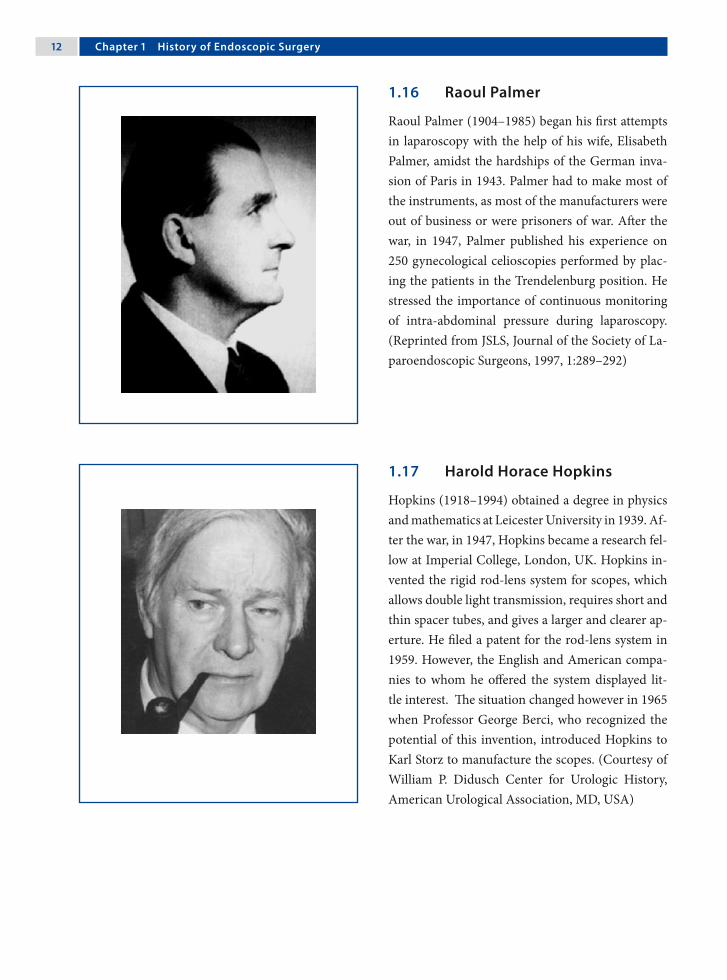
12 Chapter 1 History of Endoscopic Surgery
1.17 Harold Horace Hopkins
Hopkins (1918–1994) obtained a degree in physics and mathematics at Leicester University in 1939. Af-ter the war, in 1947, Hopkins became a research fel-low at Imperial College, London, UK. Hopkins in-vented the rigid rod-lens system for scopes, which allows double light transmission, requires short and thin spacer tubes, and gives a larger and clearer ap-erture. He filed a patent for the rod-lens system in 1959. However, the English and American compa-nies to whom he offered the system displayed lit-tle interest. The situation changed however in 1965 when Professor George Berci, who recognized the potential of this invention, introduced Hopkins to Karl Storz to manufacture the scopes. (Courtesy of William P. Didusch Center for Urologic History, American Urological Association, MD, USA)
1.16 Raoul Palmer
Raoul Palmer (1904–1985) began his first attempts in laparoscopy with the help of his wife, Elisabeth Palmer, amidst the hardships of the German inva-sion of Paris in 1943. Palmer had to make most of the instruments, as most of the manufacturers were out of business or were prisoners of war. After the war, in 1947, Palmer published his experience on 250 gynecological celioscopies performed by plac-ing the patients in the Trendelenburg position. He stressed the importance of continuous monitoring of intra-abdominal pressure during laparoscopy. (Reprinted from JSLS, Journal of the Society of La-paroendoscopic Surgeons, 1997, 1:289–292)

Amulya K. Saxena 13
1.18 Kurt Karl Stephan Semm
Kurt Karl Stephan Semm (1927–2003) was born in Munich, Germany, where he also studied medicine at the Ludwigs-Maximillian University. In 1958, he wrote his medical thesis under the guidance of No-bel laureate Adolf Butenandt. Semm began his ca-reer in gynecology under Professor Fikentscher in Munich. In 1970s, as the Head of Gynecology in Kiel, he: (1) introduced an automatic insuffla-tion device capable of monitoring intra-abdomi-nal pressures, (2) introduced endoscopic loop su-tures, (3) introduced extra- and intracorporeal su-turing techniques, and (4) created the pelvitrainer. He performed the first laparoscopic appendectomy in 1982. (Courtesy of Monika Bals-Pratsch MD, Zentrum für Gynäkologie, Universität Regensburg, Germany)
1.19 Harrith Hasson
In 1978, Harrith M. Hasson, a gynecologist in Chi-cago, IL, USA, introduced an alternative method of port placement. He proposed a blunt minilaparo-tomy that permitted direct visualization of the port entrance in the cavity. The Hasson trocar system was initially developed for laparoscopy in patients who have had a previous laparotomy. Hasson served as Assistant Professor at Northwestern University, Associate Professor at Rush University, Director of the Gynecologic Endoscopy Center and Chairman of the Division of Obstetrics & Gynecology at Weiss Memorial Hospital in Chicago, and Clinical Profes-sor at University of Chicago. He retired from clini-cal practice in 2003. (Courtesy of RealSim Systems LLC, Albuquerque, NM, USA)

1� Chapter 1 History of Endoscopic Surgery
1.21 Philippe Mouret
Philippe Mouret, a French general surgeon, rotated on a gynecology service in the 1960s, during which he had his first contact with laparoscopy. Mouret further developed interest in laparoscopy as he also shared his surgical practice with a gynecologist and had access to laparoscopic instruments and, impor-tantly, to patients requiring laparoscopy. In 1987, Mouret performed the first videolaparoscopic chol-ecystectomy in Lyons, France. Cholecystectomy is the first laparoscopic procedure that “revolution-ized” general surgery and was the stimulus in the development of operative laparoscopic surgery. (Courtesy of the Honda Foundation, Tokyo, Japan)
1.20 Erich Mühe
Erich Mühe (1938–2005) completed his medical education in 1966 and training in surgery in 1973 under Professor Gerd Hegemann at the University of Erlangen, Germany. He was later appointed as the Head of Surgery in Böblingen County Hospi-tal in 1982. In 1985, Mühe performed the first lapa-roscopic cholecystectomy. He used a modified rec-toscope and employed carbon dioxide insufflation for this procedure. As surgical instruments, he used a pistol grip applier with hemoclips to ligate, and pistol grip scissors to cut between the clipped cys-tic duct and artery. (Reprinted from JSLS, Journal of the Society of Laparoendoscopic Surgeons, 1998, 2:341–346)

Amulya K. Saxena 1�
1.22 Michael Harrison
Since the 1980s, Michael R. Harrison, a pediat-ric surgeon in San Francisco, California, USA, has been involved in fetal medicine. He performed the first open fetal surgical procedure in 1981. In 1997, Harrison performed the first successful clipping of the trachea using minimal access “fetoscopic tech-niques” by placing the Fetendo clip into a human fetus with a congenital diaphragmatic hernia. Mi-chael Harrison is the Director of the Fetal Treat-ment Center, University of California, San Fran-cisco. Over the past two decades he has developed various techniques for minimal-access treatment of fetuses. (Courtesy of Michael Harrison, UCSF, San Francisco, CA, USA)
Recommended Literature
1. Modlin IM, Kidd M, Lye KD (2004) From the lumen to the laparoscope. Arch Surg 139:1110–1126
2. Spaner SJ, Warnock GL (1997) A brief history of en-doscopy, laparoscopy, and laparoscopic surgery. J La-paroendosc Adv Surg Tech A 7:369–373
3. Vecchio R, MacFayden BV, Falazzo F (2000) History of laparoscopic surgery. Panminerva Med 42:87–90

2.1 Port and Trocar
A port is a tubular sleeve-like device through which operative access is obtained in endoscopic surgery. A trocar is a spike-like device (conical- or pyrami-dal-tipped) that is placed inside the port sleeve with its tip exposed toward the end of the port. The port and trocar are inserted as a set through the abdomi-nal or chest wall, and the trocar is removed after the port is in place. The port has a valve mechanism to allow instruments to be passed through it without the loss of insufflated gases. (Courtesy of Richard Wolf, Knittlingen, Germany)
2 Instrumentation and EquipmentAmulya K. Saxena

1� Chapter 2 Instrumentation and Equipment
2.2 Veress Needle
A Veress needle is used for creating the initial pneu-moperitoneum so that the subsequent trocars and ports can enter safely. It consists of an inner cannula that is spring-loaded and retracts within the sharp outer needle while passing through the anterior
wall, and then springs forward when it is in the open cavity. The inner cannula is sealed at the distal end, but has a hole on the side of the tip (inset) for the gas to flow through. The Veress needle should be checked for its patency and spring action prior to use. (Cour-tesy of Richard Wolf, Knittlingen, Germany)
2.3 Blunt Grasping Forceps
Blunt graspers are the principle means of manipulat-ing tissue and providing exposure to the operation site. It is compulsory that each endoscopic surgery set has at least two pairs of graspers. Blunt grasp-ers have opposing jaws with fine, parallel grooves. They may have a single-action (inset above) or dou-ble-action (inset below) jaw mechanism. The han-dle may be a scissor grip, spring loaded or ratcheted (see Figure). The handles and bodies of the graspers should be insulated, but should have the possibil-ity for use with electrosurgery. (Courtesy of Richard Wolf, Knittlingen, Germany)

Amulya K. Saxena 1�
2.4 Dissectors and Tissue Extractors
Various types of endoscopic scissors are available for sharp dissection. However, the hook scissor (inset) is a special scissor used in endoscopic surgery in that its unique blade shape helps to withdraw the tissue into the grasp prior to completing the cut. This is
advantageous when a relatively large amount of tis-sue has to be cut. (Courtesy of Richard Wolf, Knitt-lingen, Germany)
Tissue extractors are single-action jaw forceps with ratchet teeth that permit a greater force to be applied to extract tissues.
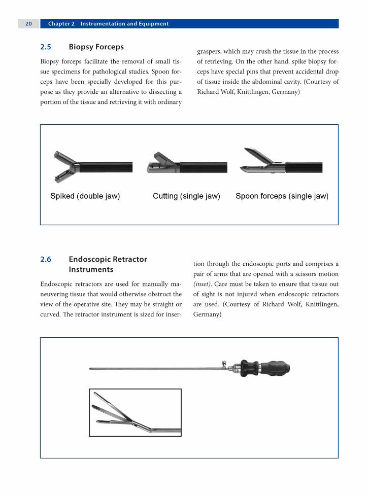
20 Chapter 2 Instrumentation and Equipment
2.5 Biopsy Forceps
Biopsy forceps facilitate the removal of small tis-sue specimens for pathological studies. Spoon for-ceps have been specially developed for this pur-pose as they provide an alternative to dissecting a portion of the tissue and retrieving it with ordinary
graspers, which may crush the tissue in the process of retrieving. On the other hand, spike biopsy for-ceps have special pins that prevent accidental drop of tissue inside the abdominal cavity. (Courtesy of Richard Wolf, Knittlingen, Germany)
2.6 Endoscopic Retractor Instruments
Endoscopic retractors are used for manually ma-neuvering tissue that would otherwise obstruct the view of the operative site. They may be straight or curved. The retractor instrument is sized for inser-
tion through the endoscopic ports and comprises a pair of arms that are opened with a scissors motion (inset). Care must be taken to ensure that tissue out of sight is not injured when endoscopic retractors are used. (Courtesy of Richard Wolf, Knittlingen, Germany)

Amulya K. Saxena 21
2.7 Needle Holders
Various types of handle grips are offered to max-imize the ergonomics of suturing and knot tying. However, most surgeons prefer the axial handle as this ergonomic design reduces hand fatigue and provides optimal as well as efficient needle control. A variety of tip styles (straight to curved) have been developed over the years, leading to an improve-ment in the design of needle holders. However, the curved tip is used at most centers to tie knots. (Courtesy of Richard Wolf, Knittlingen, Germany)
2.8 Knot Pushers
A surgical knot-pusher device allows a prepared knot to be pushed down through the length of the suture. The device includes a handle and an elon-gated body extending from it (above). The elon-
gated body has a curved tip that is tapered and has a groove along the length of the tip (inset). Modular knot pushers (below) have grooves in both the prongs and function on the same principle as the rod type. (Courtesy of Richard Wolf, Knittlingen, Germany)

22 Chapter 2 Instrumentation and Equipment
2.9 Probes
Probes are blunt instruments that are utilized to manipulate tissues. Depending on the type of manipulation required, the following types can be
used: (1) graduated, (2) hook, and (3) palpation. Hooked probes are generally used for lifting struc-tures that also need to be palpated. (Courtesy of Richard Wolf, Knittlingen, Germany)
2.10 Goldfinger® Dissector
The Goldfinger® dissector (Johnson & Johnson Medical Products, Ethicon Endo-Surgery, Cincin-nati, OH, USA) is a tool developed for bariatric sur-gery that aids in the placement of the gastric band. The tip of the Goldfinger dissector can flex 90° in the vertical axis, which is similar to the movement ob-
tained by flexing a finger. The tool is passed behind the esophagus and is pushed back up through the opening made in the gastophrenic ligament, where the thread loop of the gastric band is secured to it. (Courtesy of Johnson & Johnson Medical Products, Ethicon Endo-Surgery, Vienna, Austria)

Amulya K. Saxena 23
2.11 Endoscopic Clip Applicators
Titanium is the most widely used metal in minimal-access surgery for tissue approximation. An endo-scopic clip applicator is a device that allows appli-cation of clips within body cavities. Titanium clips
are held in position by a dumbbell formation of the tissue they are applied on. If the clips are applied very close to each other, the dumbbell formation will be nullified and the clips will fall loose. (Cour-tesy of Richard Wolf, Knittlingen, Germany)
2.12 Endoscopic Linear Stapler
An endoscopic linear stapler device is able to elim-inate most of the need for suturing within the sur-gical cavity. It comprises a single-use loading unit with titanium staples for resection, transection
and anastomosis. Care should be taken in port se-lection, as endoscopic staplers are only available in the 10-mm size. (Courtesy of Johnson & Johnson Medical Products, Ethicon Endo-Surgery, Vienna, Austria)

2� Chapter 2 Instrumentation and Equipment
2.13 Circular Intraluminal Anastomosis Stapler
The end-to-end anastomosis stapler enables a cir-cular intraluminal anastomosis of the bowel by placing a double-staggered row of titanium staples.
The instrument is activated by squeezing the han-dles firmly. Immediately after staple formation, a knife blade in the instrument resects the excess tis-sue. (Courtesy of Johnson & Johnson Medical Prod-ucts, Ethicon Endo-Surgery, Vienna, Austria)
2.14 Specimen Retrieval Bags
Specimen retrieval bags are designed to enable the safe retrieval and extraction of tissues from the body without spillage or contamination. The bags are made of polyurethane to eliminate porosity and provide the necessary strength. Two support arms help to facilitate bag opening and tissue capture. The bag and support arms are attached to a shaft and introducer to facilitate their use in laparoscopic procedures. Each bag is a sterile, single-patient-use, disposable product. (Courtesy of Covidien Austria, Brunn am Gebirge, Austria)

Amulya K. Saxena 2�
2.15 Endoscopic Loop Suture
Endoscopic sutures are available as pretied loops. In order to apply the suture, the loop and its applica-tor are placed through an appropriate cannula and inserted into the cavity. The tissue to be ligated is grasped through the loop and then pulled to allow the loop to slide over it. The external end of the ap-plicator is then broken free and pulled to tighten the loop. The pretied Roeder knot slips forward along the suture and will stay relatively in the area where it is applied. (Courtesy of Johnson & Johnson Medical Products, Ethicon Endo-Surgery, Vienna, Austria)
2.16 Automated Laparoscope Assistance
Automatic laparoscope manipulators are systems that render an additional hand for movement or positioning of the scopes during a procedure. Such systems help in autonomous coordination of the hand and eye, directly by the surgeon. The systems are generally composed of a base unit, a mobile and mechanically adjustable arm, and a shaft holder. Recently developed units (Lapman™, Richard Wolf, Knittlingen, Germany) are delivered with an auto-clavable “hand control remote” that can be held in position in the palm of the surgeon’s hand under the sterile gloves. (Courtesy of Richard Wolf, Knit-tlingen, Germany)

2� Chapter 2 Instrumentation and Equipment
2.17 Electrosurgery Devices
2.17.1 Coagulation and Dissection
Coagulation by desiccation is performed when the instrument comes into contact with the tissue, to slowly heat and evaporate water from the tissue. This process continues until the tissue becomes des-iccated to the point that it no longer conducts elec-tric currents and an eschar is produced.
Electrosurgery equipments have controls for set-ting waveforms. The waveforms represented are cut and coagulate. The electrosurgery solid-state gener-ators start with 50 cycles of current and transform them to frequencies of more than 50,000 cycles, which is above the level of neuromuscular stimu-lation, to achieve the desired result in the tissue. (Courtesy of Richard Wolf, Knittlingen, Germany)
2.17.2 Monopolar Coagulation
In monopolar electrosurgery, current passes through the body from the active electrode (instru-ment) to the grounding electrode pad, which is at-tached to the patient’s body. Monopolar electrosur-gery is widely used and enables the surgeon to both, cut and coagulate. Along with the power level used, the efficacy of coagulation or cutting is also deter-mined by the shape of the electrode. The hooked-shaped electrode is one of the most useful devices, since cutting may be achieved either by pulling or alternatively using the heel of the hook. (Courtesy of Richard Wolf, Knittlingen, Germany)

Amulya K. Saxena 2�
2.17.3 Bipolar Coagulation
In bipolar electrosurgery, the functions of both the active electrode and return electrode are performed at the site of surgery. Only the tissue grasped is in-cluded in the electrical circuit. Because the return function is performed by one tine of the forceps, no patient return electrode is needed. This eliminates most of the safety concerns associated with mono-polar electrosurgery. Bipolar electrosurgery is gen-erally employed for captive hemostasis; however, sharp hemostatic dissection is possible with the newer configurations available. (Courtesy of Erbe Elektromedizin, Tübingen, Germany)
2.17.4 Harmonic Technology/Instruments
The Ultracision® harmonic scalpel (Johnson & John-son Medical Products, Ethicon Endo-Surgery, Cin-cinnati, OH, USA) uses ultrasound technology for precise cutting and controlled coagulation. The main benefits of this instrument are:1. Greater precision near vital structures.2. Fewer instrument exchanges.3. Minimum charring and desiccation.4. Reduced need for ligatures.5. Coagulation/cutting at lower temperatures.6. Less lateral thermal damage.7. Heat development in the tissue rather than the
instrument.8. No electrical circuit through the patient.(Courtesy of Johnson & Johnson Medical Products, Ethicon Endo-Surgery, Vienna, Austria)

2� Chapter 2 Instrumentation and Equipment
2.17.5 LigaSure™ Sealing Device
The LigaSure™ (Valleylab, Boulder, CO, USA) seal-ing device uses an optimized combination of pres-sure and energy to create seals by melting the col-lagen and elastin in the vessel walls and reforming it into a permanent, plastic-like seal. It fuses vessels up to and including 7 mm in diameter and tissue bundles without dissection or isolation. Further-more, when the instrument determines that the seal is complete, a tone sounds and output to the hand-piece is automatically discontinued. Lateral thermal spread is minimal (1–2 mm) and the unique energy output results in no sticking or charring. (Courtesy of Covidien Austria, Brunn am Gebirge, Austria)
2.18 Laser Fiber Optics
The most frequently used lasers in operative pro-cedures are argon, potassium-titanyl-phosphate (KTP) and neodymium-doped yttrium-aluminum-garnet (Nd:YAG). Laser energy is delivered to the tissues through optical fibers – fiber optics. The op-tical fiber consists of a 600-µm pure silica core sur-rounded by a low-refractive-index silica cladding. In order to prevent breakage, a covering of silicone rubber and nylon is applied. The 600-µm fiber op-tics offer the best combination of coagulation and cutting, which is combined with the appropriate amount of stiffness and flexibility. For laser applica-tion in endoscopic surgery, various laser fiber-optic delivery device options (operating scopes/reducing valve ports) are available.

Amulya K. Saxena 2�
2.18.1 Scopes and Video Camera Systems
2.18.1.1 Anatomy of a Rigid Scope
Central to the instrumentation is the scope. Its backbone is the rod lens system designed by Hop-kins. The shaft of scopes houses both light fibers and viewing optics. The viewing optics consist of three distinct parts: the objective lens, rod lenses, and ocular lens.

30 Chapter 2 Instrumentation and Equipment
2.18.1.2 Field of View
The field of view (also field of vision) is the angu-lar extent of the observable area that is seen at any given moment. The field of view in scopes for endo-scopic surgery can vary from 60° to 82° depending up on the type of instrument. Wider angles of view provide a greater depth of field in the image with better utilization of illumination. A smaller field of view allows the scope to be farther from the tissue, for the same to be observed.
2.18.1.3 Angle of View
The angle of view in scopes can vary with respect to the central axis of the scope. Scopes that offer an axis view are designated as 0° and provide a straight view of the structure in question. Scopes are also available with a 5°, 25°, 30°, 45°, and even 70° angle of view, allowing utilization of the scopes much as a periscope. The off-axis scopes enable one to observe down into the gutters and up the anterior abdomi-nal wall as well as sideways. Off-axis scopes are dif-ficult to work with; however, they provide an excel-lent means of obtaining close inspection of tissues at difficult angles and positions.

Amulya K. Saxena 31
2.18.1.4 Scope Size and Screen Image
The decrease in the size of scopes was an import-ant factor in the advancement of minimally inva-sive surgery in the pediatric age group. Although scopes are available in sizes from 1.9 mm to 12 mm in diameter, the majority of the procedures are per-formed using 5- or 10-mm scopes.
When compared to the reduced view obtained in the previous generation of scopes (left), mod-ern 5-mm, full-screen scopes provide a bright, dis-tortion-free, full-screen image (right). In addition, the image size in modern 5-mm scope is equiva-lent to that obtained by the previous-generation 10-mm scope. (Courtesy of Richard Wolf, Knittlin-gen, Germany)
2.18.1.5 Operating Scopes
Beside the optical component and the lens system, operating scopes posses an additional work chan-nel that allows the introduction of instruments (between 3.5–5.0 mm in diameter and 220 mm in length) through the scope. These scopes have a 0° angle of view and 85° field of view. Operating scopes have been used frequently in gynecology for tubal ligations; however their use in pediatric surgery has risen with the increasing trend in single-port lapar-oscopic applications. (Courtesy of Richard Wolf, Knittlingen, Germany)

32 Chapter 2 Instrumentation and Equipment
2.18.1.6 Charge Coupled Device (CCD) Video Cameras
Scope cameras are available in either single-chip or three-chip versions (one chip offers 300,000 pixels/cm2). In single-chip CCD cameras, all the three pri-mary colors (red, blue and green) are sensed by a single chip. In three-chip CCD cameras, there are three chips for separate capture and processing of the primary colors.
Single-chip CCD cameras produce images of 450 lines/inch resolution and are ideal for outpa-tient surgery. On the other hand, three-chip CCD cameras have high fidelity with unprecedented color reproduction to produce images of 750 lines/inch resolution that can be viewed optimally on flat-panel screens and are best suited for endoscopic surgery. (Courtesy of Richard Wolf, Knittlingen, Germany)
2.19 Light Sources
2.19.1 Light-Source Generators and Transmission Pathways
There are two commonly utilized light sources: halo-gen and xenon. A schematic overview of light trans-mission is outlined in the diagram (next page).

Amulya K. Saxena 33
Lamp Light cable Increased emissionangle
Light focusing Endoscope
Lamp Light cable Increased emissionangle
Light focusing Endoscope
Halogen bulbs (250 W) provide a highly effi-cient white light source with excellent color ren-dering. Electrodes in halogen gas lamps are made of tungsten and reach color temperatures up to 5000–5600 K.
Xenon bulbs (300 W) consist of a spherical or
ellipsoidal envelope made of quartz glass. The color temperature of a xenon lamp is 6000–6400 K. Xe-non bulbs last longer than halogen, but are signifi-cantly more expensive. (Courtesy of Richard Wolf, Knittlingen, Germany)
2.19.2 Fiber-Optic Cables for Light Transmission
A fiber-optic cable is used to transmit light from the light source to the scope. Fiber-optic bundles are very flexible and are made of small, 5-µm-di-ameter fibers. Since individual fibers are subject to breakage, fractured optical cable fibers reduce the capacity to transmit light. To prevent cable break-age, the cable should be handled with care, and in-serted and removed from its socket without angling at the flexible as well as the rigid junction. Cables should never be bent at acute angles. Fiber-optic cables should be discarded when less than 75% of the fibers transmit light. (Courtesy of Richard Wolf, Knittlingen, Germany)

3� Chapter 2 Instrumentation and Equipment
2.19.3 The Concept of White Balancing
White balancing should be performed before in-serting the camera inside the abdominal cavity. This is necessary before commencing surgery to dimin-ish the added impurities of color that may be intro-duced due to a variety of reasons such as: (1) volt-age difference, (2) staining of the tip by cleaners, and (3) scratches and wear of the eyepiece.
White balancing is achieved by keeping a white object in front of the scope and activating the ap-propriate button on the video system or camera. The camera senses the white object as its refer-ence to adjust all of the primary colors (red, blue and green). (Courtesy of Richard Wolf, Knittlingen, Germany)
2.20 Insufflation, Irrigation and Aspiration Devices
2.20.1 Insufflation Devices
Modern insufflators automatically monitor and regulate the internal pressure of the abdominal cav-ity. Insufflators have four clearly visible gauges: (1) a carbon dioxide (CO2) flow rate indicator (maxi-mum 10 l/min), (2) a CO2 cylindrical pressure in-dicator, (3) a total volume of gas delivered indica-tor, and (4) an intra-abdominal pressure indicator. A filter is placed between the insufflators and ster-ile tubing attached to ports. The required values for pressure and flow can be set precisely using digital displays. (Courtesy of Richard Wolf, Knittlingen, Germany)

Amulya K. Saxena 3�
2.20.2 Concepts in Irrigation and Aspiration
Vision is one of the limitations of endoscopic sur-gery. Blood has the darkest color inside the abdom-inal cavity and excess of blood therein absorbs most of the light. So, whenever there is bleeding during endoscopic procedures, blood should first be aspi-rated before irrigating to prevent reduction of vi-sion. Aspiration of fluids and washing of tissues to enable better visualization is accomplished with an irrigation/aspiration system. The instrument that is used to gently spray the irrigation solution is also employed to aspirate the irrigant. Suction/irrigation instruments can also be used for blunt dissection. (Courtesy of Richard Wolf, Knittlingen, Germany)
2.20.3 Instruments for Irrigation and Aspiration
Irrigation/aspiration instruments for endoscopic procedures are available in a variety of handle- and tip-form combinations. Furthermore, some hand instruments, especially those designed for electro-surgical dissection, have channels within for aspira-tion of smoke from the surgical site.
At the time of using suction, it is important to visualize the tip of the irrigation/suction instru-ment and ensure that it is dipped inside blood or other fluid to be evacuated. If not completely im-mersed, a loss of insufflated gas will occur. (Cour-tesy of Richard Wolf, Knittlingen, Germany)

3� Chapter 2 Instrumentation and Equipment
2.21 Video and Data Storage Equipment
2.21.1 Digital Video Recorders
Modern endoscopic surgery towers are generally equipped with digital video disc (DVD) record-ers (DVRs), which enable recording of a procedure in digital quality. The procedures are recorded on commercially available DVDs, which can later be viewed on normal DVD players or edited on per-sonal computers.
DVRs have evolved into devices that are fea-ture rich and provide services that exceed the sim-ple recording of video images that was previously achieved using video cassette recorders (VCRs). DVR systems provide a multitude of advanced func-tions, including video searches by event and time.
2.21.2 Digital Video Printers
A variety of printers from small print format to large A5 print format are available. These printers offer high-resolution prints, quick, 20-s print time, and high-quality, curl-free prints at 400 dpi resolu-tion. Most modern printers come with a four-frame memory. The new compact design of printers al-lows for easy integration with other video equip-ment. Small, compact printers are ideal for the of-fice setting, but large-print format printers are pref-erable in the operating room.

Amulya K. Saxena 3�
2.21.3 Digital Video Managers
These are computer-based systems that display in-tuitive patient information screens that allow for quick and easy input of vital data. The data is stored on hard drives and can be viewed as images or videos, and may be stored or deleted. The editing screen enables viewing and editing procedures.
Current systems allow storage of up to 50 pa-tient archives for multiple procedures. These sys-tems are compatible with personal computers and hospital network software. (Courtesy of Richard Wolf, Knittlingen, Germany)
2.21.4 Flat-Panel Screens
The industry offers a variety of high-quality LCD monitors with ultrasharp detail and perfect color rendition. The 14-inch medical and non-medical-grade monitors including stand-alone and built-in audio speaker are ideal for office endoscopy; how-ever, 19-, 21-, and 23-inch medical-grade monitors are presently an integral component of video carts and are ideal for endoscopic surgery visualizations. Due to their light weight, flat-panel monitors can be held by swivel arms on video carts. (Courtesy of Richard Wolf, Knittlingen, Germany)

3� Chapter 2 Instrumentation and Equipment
2.21.5 Endoscopic Surgery Towers
Endoscopic surgery towers are mobile carts that house the equipment. Their mobility enables the placement of equipment according to the proce-dure and position of the team. Standard towers con-sist of:1. Monitors.2. Video processing equipment.3. Light-source generator.4. Gas (CO2) insufflator.5. Aspiration/suction device.6. Documentation equipment.7. Stand for CO2 cylinder.(Courtesy of Richard Wolf, Knittlingen, Germany)
2.22 Trainers for Endoscopic Surgery
2.22.1 Pelvitrainers
A realistic surgical training requires an anatomical model that allows the easy integration of animal or-gans. The regular repetition of procedures demands quick preparation of the training setup with opti-mal fixation of the organs within the pelvitrainers.
Modern trainers such as the Tübingen MIC Trainer™ (Richard Wolf, Knittlingen, Germany) have realistic anatomical shape that simulates the frontal abdominal wall of an insufflated patient, and covers that deliver a reality effect for the introduc-tion of the trocars and ports. (Courtesy of Richard Wolf, Knittlingen, Germany)

Amulya K. Saxena 3�
2.22.2 Virtual Reality Simulators
The LapSim® System (Surgical Science Sweden, Göteburg, Sweden) is a digital training aid that re-places the vulnerable patient with expendable pixels. By recreating digitally the procedures and envi-ronment of endoscopic surgery, LapSim® provides an effective training tool for endoscopic surgeons. Augmenting surgical training with simulation offers great promise because maneuvers can be practiced over and over until they are mastered. (Courtesy of Surgical Science Sweden, Göteborg, Sweden)
Recommended Literature
1. Chmarra MK, Grimbergen CA, Dankelman J (2007) Systems for tracking minimally invasive surgical instruments. Minim Invasive Ther Allied Technol 17:1–13
2. Mercy CM, Cooke DT, Chandra V, Shafi BM, Tavak-kolizadeh A, Varghese TK (2007) The road to innova-tion: emerging technologies in surgery. Bull Am Coll Surg 92:19–33
3. Eriksen JR, Grantcharov T (2005) Objective assess-ment of laparoscopic skills using a virtual reality stimu-lator. Surg Endosc 19:1216–1219
NOTE
Tyco Healthcare is now Covidien (Covidien, Mansfield, MA, USA) with endoscopic surgery product brands- Autosuture (division of United States Surgical -USS), Valleylab and Syneture.

3.1 Introduction
3.1.1 Indications for Endoscopic Surgery
There must be a demonstrable advantage to the pa-tient (i.e., rapid return to normal function; cosmetic advantage; decreased complications).
3.1.2 Requirement for Procedures
Endoscopic surgery requires advanced surgical and nursing training in the purchase and use of the equipment and instrumentation.
3.1.3 Complications
Most are related to equipment misuse/failure and improper surgical access.
3.2 Definition and Aim
Ergonomics is the application of scientific informa-tion to the design of objects, systems, and the envi-ronment for human use (International Ergonomic Association). The aim of ergonomics in endoscopic surgery is to improve human performance, decrease surgical fatigue, and minimize the dangers and dis-advantages. Thus, operating room design requires input from an ergonomic expert, and surgeons and nurses trained in endoscopic surgery.
3.3 Operating Room Requirements
1. Adequate room size.2. Room/endoscopic surgery light sources.3. Multiple adjustable and mobile monitors.4. Carbon dioxide insufflation.5. Endoscopic suction and irrigation.6. Electrosurgery, laser, harmonic scalpel.7. Radiological imaging.8. Anesthetic equipment.9. Specialized operating table.
3.4 Manpower Requirements
1. Surgeon trained in endoscopic surgery.2. Surgical assistant experienced in use of the cam-
era.3. Second surgical assistant.4. Nurses trained in endoscopic surgery.5. Anesthetist trained in endoscopic surgery.
3 Ergonomics of Endoscopic SurgerySteven Z. Rubin and Marcos Bettolli
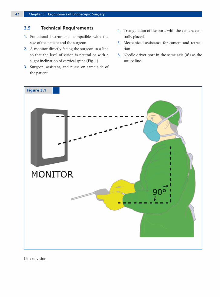
�2 Chapter 3 Ergonomics of Endoscopic Surgery
Figure 3.1
3.5 Technical Requirements
1. Functional instruments compatible with the size of the patient and the surgeon.
2. A monitor directly facing the surgeon in a line so that the level of vision is neutral or with a slight inclination of cervical spine (Fig. 1).
3. Surgeon, assistant, and nurse on same side of the patient.
4. Triangulation of the ports with the camera cen-trally placed.
5. Mechanized assistance for camera and retrac-tion.
6. Needle driver port in the same axis (0°) as the suture line.
Line of vision
Steven Z. Rubin and Marcos Bettolli �3
3.6 Robotics
The advantages of robotic systems are many since they overcome many of the obstacles of endoscopic surgery. They increase dexterity, restore proper hand-eye coordination and an ergonomic position, and improve visualization. In addition, these sys-tems make possible surgeries that were previously technically difficult. However, at present there is no evidence-based ergonomic advantage for robotics in pediatric endoscopic surgery.
3.7 Improvement of Team Performance
1. Using training courses and human reliability analysis.
2. Using a surgical team; this is better than one bi-manual surgeon.
3. The surgeon is preferably seated.4. Using ultrasound, computed tomography, and
magnetic resonance imaging to display vessels, nerves and tumors.
5. Team review of advanced procedures both pre- and postoperatively.
6. Improve procedure visualization using over-head illumination, gravity, and optimizing cam-era position.
3.8 The Future
1. Improved ergonomic operating room and equipment design with integrated systems un-der the control of the operating surgeon.
2. The development of an endoscopic pointer us-ing ultrasound, computed tomography, and magnetic resonance imaging to identify vessels and anatomical relationships.
3. Instruments that intraoperatively adjust to the surgeon’s hand size and the size of the patient.

�� Chapter 3 Ergonomics of Endoscopic Surgery
Figure 3.2
3.9 Operating Staff Positions and Ergonomics
3.9.1 Single-Monitor Option
If a single monitor or flat screen panel is used, it should be positioned suitably to allow sufficient vi-sion to the operating team (Fig. 2). This option is practical when the entire operating team stands on one side.
Single-monitor option

Steven Z. Rubin and Marcos Bettolli ��
3.9.2 Dual-Monitor Option
If the operating team is dispersed around the oper-ating table it is advisable to have two monitors so that the entire team has visible access irrespective of their position (Fig. 3).
Figure 3.3
Dual-monitor option

�� Chapter 3 Ergonomics of Endoscopic Surgery
3.9.3 Ventilator vs. Monitor Placement
It is often difficult to position the tower toward the head of the patient since this place is occupied by
the anesthetist and the ventilation equipment. A swivel flat screen is helpful to overcome this prob-lem (Fig. 4).
Figure 3.4
Recommended Literature
1. Catchpole K, Mishra A, Handa A, McCulloch P (2008) Teamwork and error in the operation room: analysis of skills and roles. Ann Surg 247:699–706
2. Hanna GB (1999) Ergonomics of task performance in endoscopic surgery. In: Bax NMA, Georgeson KE,
Najmaldin A, Valla J-S (eds) Endoscopic Surgery in Children. Springer-Verlag, Berlin, pp 37–47
3. Zehetner J, Kaltenbacher A, Wayand W, Shamiyeh A (2006) Screen height as an ergonomic factor in laparo-scopic surgery. Surg Endosc 20:139–141
Ventilator vs. monitor placement
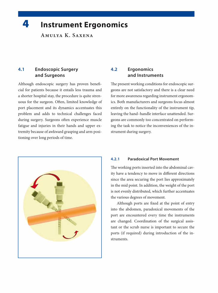
4.1 Endoscopic Surgery and Surgeons
Although endoscopic surgery has proven benefi-cial for patients because it entails less trauma and a shorter hospital stay, the procedure is quite stren-uous for the surgeon. Often, limited knowledge of port placement and its dynamics accentuates this problem and adds to technical challenges faced during surgery. Surgeons often experience muscle fatigue and injuries in their hands and upper ex-tremity because of awkward grasping and arm posi-tioning over long periods of time.
4.2 Ergonomics and Instruments
The present working conditions for endoscopic sur-geons are not satisfactory and there is a clear need for more awareness regarding instrument ergonom-ics. Both manufacturers and surgeons focus almost entirely on the functionality of the instrument tip, leaving the hand–handle interface unattended. Sur-geons are commonly too concentrated on perform-ing the task to notice the inconveniences of the in-strument during surgery.
4.2.1 Paradoxical Port Movement
The working ports inserted into the abdominal cav-ity have a tendency to move in different directions since the area securing the port lies approximately in the mid point. In addition, the weight of the port is not evenly distributed, which further accentuates the various degrees of movement.
Although ports are fixed at the point of entry into the abdomen, paradoxical movements of the port are encountered every time the instruments are changed. Coordination of the surgical assis-tant or the scrub nurse is important to secure the ports (if required) during introduction of the in-struments.
4 Instrument ErgonomicsAmulya K. Saxena

�� Chapter � Instrument Ergonomics
4.2.2 Working Field Perimeters
Working ports have a cone-shaped field inside and outside the abdomen. The degree of movements of both of the fields should be borne in mind when in-troducing the ports through the body cavities. The limitations of work fields require good understand-ing so as to enable the easy manipulation of tissue. Narrow work field parameters can lead to extreme technical difficulties when suturing and knot tying. An optimal work field must be worked out before any endoscopic surgery procedure is carried out.
4.2.3 Instrument Cluttering
Crowding of instruments in the abdominal cavity does not provide better access. It only leads to in-creased confusion and further increases the techni-cal difficulties in trying to achieve the desired ob-jective. Optimal number of instruments for en-doscopic surgery must be utilized not only in ad-vanced procedures, but also in basic ones.
In the pediatric abdomen, which is even smaller than that of the adult, this practice of instrument cluttering should be avoided. Instrument clutter-ing may be responsible for adjacent tissue injuries, since the attention of the surgeon is diverted away from the passively used instruments.

Amulya K. Saxena ��
4.2.4 Working Angles
Optimum working angles are necessary for de-sired tissue manipulation. However, it is of para-mount importance to have the best working angles in endoscopic procedures that require suturing and knotting.
A distance of 10 cm between the working ports outside the body cavity, if possible, provides a rela-tively good suturing field. However, inside the body cavity, a working distance of 4 cm is desired at the point where the tips of the needle holders meet to enable comfortable suturing and knotting.
4.2.5 Handle Design
The handle is the instrument’s interface, where the surgeon can interact with the instrument. A good indication of a functional instrument is when the surgeon can forget about the tool and just concen-trate on the job. The hand–handle interface should be “invisible” so that the tool can function merely as an extension of the arm.
4.2.6 Power Grip and Precision
The classic categorization of grips distinguishes power grips from precision grips. A power grip re-quires great force but little precision and vice versa. Both power-, precision, and combination grips function optimally when the hand is in its neutral position. This characteristic of grips stresses the im-portance of keeping the wrist in a neutral position.
4.2.7 Hand and Wrist Movements
The most important positioning of the hand is called the neutral position, or the position of rest. This occurs typically when the hand is resting in a palm-medial position with fingers slightly flexed. It is the most comfortable hand position and it is also the situation in which the hand can perform opti-mally with both force and precision.
4.2.8 Adaptation for Various Hand Sizes
The instrument handle should provide usability for all surgeons or be adjustable to all its users’ vari-ous hand sizes, as individual fitting is often not pos- sible with today’s mass-production. For endoscopic instruments, hand size is an important determinant of difficulty of use. Individuals with small hands ex-perience problems more commonly than those with large hand sizes.

�0 Chapter � Instrument Ergonomics
4.2.8.1 Handle Grip Diameter
The handle should be of such a size that it permits slight overlap of the thumb and fingers of a sur-geon with small hands. A handle diameter of 40–50 mm can provide sufficient support as well as al-low strength to be applied for most surgeons. If the handle is too small it will not allow proper force ex-ertion, but at the same time, strength deteriorates with a handle size above 50 mm.
4.2.8.2 Handle Length and Cross-Section
Handle lengths should be at least 115 mm and al-low clearance for extra large hands. If gloves are to be used, extra length must be added depending on glove type and thickness. Handles of circular cross-section (and appropriate diameter, e.g., 30–50 mm) are the most comfortable to grip.
4.2.9 Buttons and Springs
In endoscopic surgery the result of the procedure is determined by the surgeon’s ability to keep the in-strument steady during manipulation. Awkwardly positioned buttons and springs that require great force to be operated can result in jeopardizing the movements of the instrument tip. It should be pos-sible for the user to operate buttons and springs without major repositioning of the fingers.
4.2.10 Multifunctionality of Handles
Putting too many functions in one handle can ren-der its use more difficult to learn, harder to re-member, or simply confusing for surgeons. It is es-pecially important to keep the functionality of the handle simple when the task itself is complicated, as in endoscopic surgery.
When it comes to endoscopic surgical instru-ments, less is really a lot more.
Recommended Literature
1. Berguer R, Hreljac A (2004) The relationship between hand size and difficulty using surgical instruments: A survey of 726 laparoscopic surgeons. Surg Endosc 18:508–512
2. van Veelan MA, Meijer DW, Goossens RHM, Snijders CJ, Jakimowicz JJ (2001) Improved usability of a new handle design for laparoscopic dissection forceps. Surg Endosc 16:201—207
3. Vereczkel A, Bubb H, Feussner H (2003) Laparoscopic surgery and ergonomics – it’s time to think of ourselves as well. Surg Endosc 17:1680–1682

5.1 Endoscopic Suturing
The endoscopic knots presently practiced are basi-cally a modification of knots used by seamen, fish-ermen, weavers, or hangmen.
There are three stages of knot tying: 1. configuration (tying), 2. shaping (drawing), and3. securing (locking or snuggling). For a knot to be perfect, all the stages of knot tying should be accurate.
5.2 Parameters Influencing Intracorporeal Suturing
1. Angle of the instruments at the suture area.2. Space around the suture site.3. Length of the suture.4. Constant and stable view and quality of the
screen picture.5. Angle of the needle in the needle holder.6. Angle of the needle to be passed through the
tissue.7. Conflicts of the needle holder with other instru-
ments.8. Natural bias of the suture.9. Tension of the tissue to be approximated.10.Personal skill and technique.
5.3 Endoscopic Needle Shapes
Half-circle needles are too large to pass through the ports. Flattened needle forms are preferred to over-come the shape and size disparity of half-circle nee-dles. Ski-shaped needles are the most reliable ones for endoscopic suturing and combine the advan-tages of the curved and flattened designs.
5 Suturing TechniquesLutz Stroedter

�2 Chapter � Suturing Techniques
5.4 Endoscopic Suture Materials
Sterile, packed, absorbable and nonabsorbable su-ture materials are available for endoscopic proce-dures:1. Polydiaxone (PDS™ ‡) is a monofilament, absorb-
able, long-lasting, and strong suture material.2. Polyglactin (Vicryl™ ‡) is a plaited, absorbable,
medium-lasting, and strong suture material.3. Polyester (Ethibond™ ‡) and silk. Polyester is a
plaited, nonabsorbable, strong suture material for permanent organ fixation.
4. Polypropylene (Prolene™ ‡) is a monofilament, nonabsorbable suture that can also be used for permanent fixation.
(‡ Ethicon, Somerville, NJ, USA)
5.4.1 Ski Needle
Ski needles are available in different sizes and armed with different suture material. The surgeon can bend the proximal two-thirds of a normal circ-led needle and convert it into a ski needle.

Lutz Stroedter �3
5.4.2 Extracorporeal Knot Tying
Extracorporeal knot tying is a method of avoiding the difficult and time-consuming skill of intracor-poreal knot tying, and is equally effective. The knot is tied outside the body and then slipped inside us-ing a knot-pusher device. The suture has to be long enough (45–90 cm) to pass from outside the port to the target tissue and back out through the port. The only disadvantage is the wastage of suture material.
5.4.2.1 Types of Extracorporeal Knots
Extracorporeal knots are normal single- or double- hitch knots followed by one or two single-hitch knots, all of which are slid down separately, like in open surgery. However, extracoporeal tied slip knots can also be employed. The most commonly used extracorporeal tied slip knots are the Roeder knot (see figure for technique), Meltzer slip knot, and the Tayside knot.

�� Chapter � Suturing Techniques
5.4.2.2 Extracorporeal Knot-Tying Technique
Please see Figs. 1–6.
Figure 5.4
Figure 5.2
Figure 5.3
Figure 5.1
The full-length suture is introduced and the tissue is approximated with the suture
The suture is retrieved from the same port where it was introduced. The suture site should be observed on the monitor to avoid excessive tension and tears of the tissue
The suture ends are tied extracorporeally Holding both the sutures in one hand, the knot is then pushed using a knot-pusher

Lutz Stroedter ��
Figure 5.5 Figure 5.6
5.4.3 Intracorporeal Knot Tying
Intracorporeal knots are tied with the help of a nee-dle holder within the body cavity. The suture should have a minimum length of approx 10 cm and should not exceed 20 cm for comfortable tying.
There are five types of intracorporeal knots: • square knot• surgeon’s knot• tumble square knot• Dundee jamming knot • Aberdeen termination knot
5.4.3.1 Tips for Intracorporeal Knot Tying
1. If the tissue is under tension and a double wrap is insufficient to hold the tension, two single wraps can be made to create a slip knot.
2. Never pull the needle in the needle holder when not sighted on the monitor. This can lead to tis-sue damage.
3. Do not pull the needle to tighten the suture. This can cause the suture to detach from the needle.
4. Tying intracorporeal knots is easiest when the instruments meet at an angle of 45–80° at the target tissue.
Care should be taken to direct the knot-pusher away from the wound edge
The second knot is tied and pushed holding one su-ture end under slight tension

�� Chapter � Suturing Techniques
5.4.3.2 Intracorporeal Suturing with a Half-Circle Needle
Please see Figs. 7 and 8.
Figure 5.7 Figure 5.8
Half-circle needles are too large to pass through the ports and can be introduced directly through the abdominal wall
The needle is grasped and the suture is tied intra-corporeally. After this, the needle can be removed either (a) back through the abdominal wall or (b) through the port site along with the port as a single unit (with loss of insufflation in this case)

Lutz Stroedter ��
5.4.3.3 Intracorporeal Knot-Tying Technique
Please see Figs. 9–14.
Figure 5.9 Figure 5.10
Figure 5.11 Figure 5.12
The needle is approximated. The suture is passed through the tissue with the needle held by the dom-inant needle holder
The needle is received by the nondominant needle holder and pulled so that it can be grasped by the dominant needle holder. The suture is pulled and laid in the form of a tension-free C-loop
With the needle held in the dominant needle holder, the suture is then wrapped twice over the nondom-inant needle holder
The nondominant needle holder is used to grasp the tail of the suture and pull to cinch down the knot

�� Chapter � Suturing Techniques
Recommended Literature
1. Brown SI, White G, Witpat K, Frank TG, Cuschieri A (2004) Improving the retention of suturing needles in surgical graspers. Surg Endosc 18:1605–1607
2. Croce E, Olmi S (2000) Intracorporeal knot-tying and suturing techniques in laparoscopic surgery: technical details. JSLS 4:17–22
3. Joice P, Hanna GB, Cuschieri A (1998) Ergonomic evaluation of laparoscopic bowel suturing. Am J Surg 176:373–378
Figure 5.13 Figure 5.14
The second wrap is a single reverse wrap to secure the first knot
The second wrap is completed by wrapping the su-ture on the dominant needle holder and pulling the free end to tie the first knot. The third single wrap is made to place a second knot on the first one

6.1 Insufflating Gas Properties
The ideal properties of insufflation gas are:1. Minimal peritoneal absorption.2. Minimal physiological effects.3. Rapid excretion.4. Noncombustible.5. Minimal effect after vascular embolization.6. High solubility in blood.
No gas at present fulfils all of these criteria; how-ever, carbon dioxide (CO2) could be considered as the closest for endoscopic surgery.
This chapter deals on the effects of insufflated gases in laparoscopic surgery (for thoracoscopic surgery see Chap. 10).
6.2 Gas Delivery Systems
Gas delivery systems are composed of a contain-ment cylinder, insufflator, tubing, filter, and ab-dominal entry device or port. The cylinders con-tain the gas as a liquid under pressure of 57 atm (5775.5 kPa). Over time, the cylinders build up in-organic and organic contamination, thus requiring filtration of the gas prior to insufflation of a patient’s thorax or abdomen.
6.3 The Jewel-Thompson Effect
The pressure change from the containment cylin-der to the insufflator and into the patient’s abdo-men/thorax causes cooling according to the Jewel-Thompson effect. The temperature of CO2 gas is about 20.1°C as it enters the abdomen. Gas flow contributes to hypothermia by convection effects. The net effect is a loss of 0.3°C per 60 l of gas in-sufflated.
6.4 Insufflation Flow Values
Flow should be started at an initial rate of 0.5 l/min to rule out any obstruction. Once the pneumoperitoneum/pneumothorax has been es-tablished the insufflation rate can be changed to a higher setting of approximately 0.5–2 l/min to speed up the process. When the limit is reached, the rate of flow can be decreased to 0.1–0.2 l/min.
6 Effects of InsufflationAmulya K. Saxena
�0 Chapter � Effects of Insufflation
6.5 Water Content of Gases
The gases used for pneumoperitoneum have low water content. The water content of CO2 is less than 200 ppm. Dry insufflation gases cause drying of the peritoneum and result in intact mesothelial cells being lost or desiccated from the peritoneum sur-face. Continuous or intermittent moistening should be performed in order to preserve peritoneal sur-face integrity and to decrease the tendency toward adhesion formation.
6.6 Insufflation Pressures
The surgeon decides upon the desired pressures re-quired for the pneumoperitoneum. Although no absolute values can be recommended, pressures in the following ranges are considered to be safe:1. 6–8 mmHg for infants.2. 8–12 mmHg for small children.3. 12–15 mmHg for older children/adolescents.For thoracoscopic procedures lower pressures be-tween 4–8 mmHg are recommended.
6.7 Dynamic Condition
The inactive and invisible pneumoperitoneum is not a static condition and must not be ignored in endoscopic surgery. The pneumoperitoneum is a dynamic space that affects the patient’s condition and specific physiologic cellular processes.
The insufflation gas needs to be: 1. filtered to reduce contamination, 2. heated to reduce hypothermia, and 3. hydrated to preserve cellular integrity and re-
duce adhesion formation.
6.8 Stress/Immunologic Responses
Changes in systemic inflammatory and anti-inflam-matory parameters (mainly cytokines) as well as in stress response parameters are less pronounced af-ter laparoscopic surgery than after conventional surgery. Whether this leads to clinically relevant ef-fects (e.g., less pain, fatigue, and complications) re-mains to be proven. There is no compelling clinical evidence that specific modifications of the pneumo-peritoneum alter the immunological response.
6.9 Physiological Changes From CO₂
Physiological changes during laparoscopic surgery are related mainly to the increased intra-abdom-inal pressure (IAP) associated with CO2 insuffla-tion of the abdomen, the patient’s postural modifi-cations (head-up or head-down), and CO2 absorp-tion. During pneumoperitoneum, younger children absorb proportionately more CO2 than older indi-viduals.
6.10 Cardiopulmonary Effects
Increases in IAP affect both ventilation and circu-lation. Increased IAP induces a mechanical com-pression of the diaphragm that reduces pulmo-nary compliance, vital capacity, functional resid-ual capacity, basilar alveolar collapse, and total lung volume. Pneumoperitoneum in children has a ma-jor impact on cardiac volumes and function, mainly through the effect on ventricular load conditions.

Amulya K. Saxena �1
6.11 Combustion Under Low Oxygen Content
1. Combustion processes that occur in low-oxy-gen environments cause elevated carbon mon-oxide emissions.
2. Peritoneal absorption of carbon monoxide causes carboxyhemoglobin formation.
3. The affinity of carbon monoxide for hemoglo-bin is 200–240 times greater than that of oxy-gen.
4. Carbon monoxide can cause cardiac arrhyth-mias and exacerbate complications.
5. Hence, smoke within the pneumoperitoneum should be intermittently evacuated.
6.12 Venous Blood Return
1. During laparoscopy, both the head-up position and elevated IAP independently reduce venous blood return from the lower extremities.
2. Intraoperative sequential intermittent pneu-matic compression of the lower extremities ef-fectively reduces venous stasis during pneumo-peritoneum and is recommended for prolonged laparoscopic procedures.
3. The true incidence of thromboembolic compli-cations after pneumoperitoneum is not known.
6.13 Methemoglobinemia
1. Methemoglobinemia may occur during tissue combustion.
2. Methemoglobin is the oxidative product of he-moglobin causing the reduced ferrous to be converted to the ferric form.
3. The difference between methemoglobin and oxyhemoglobin in the ferric state is that methe-moglobin is formed from unoxygenated hemo-globin and is not capable of carrying either oxy-gen or CO2.
4. This property shifts the oxyhemoglobin dissoci-ation curve to the left, inhibiting oxygen deliv-ery to tissues.
6.14 Intra-abdominal Organ Perfusion
Although in healthy subjects changes in kidney or liver perfusion and also splanchnic perfusion due to an IAP of 12–14 mmHg have no clinically rele-vant effects on organ function, this may not be the case in patients with already impaired perfusion. In particular, in patients with impaired hepatic or re-nal function or atherosclerosis, the IAP should be as low as possible to reduce microcirculatory dis-turbances.
�2 Chapter � Effects of Insufflation
Recommended Literature
1. Balick-Weber CC, Nicholas P, Hedreville-Montout M, Blanchet P, Stephan F (2007) Respiratory and haemo-dynamic effects of volume-controlled vs pressure-con-trolled ventilation during laparoscopy: a cross-over study with echocardiographic assessment. Br J Anaesth 99:429–435
2. De Waal EE, Kalkman CJ (2003) Haemodynamic changes during low-pressure carbon dioxide pneu-moperitoneum in young children. Paediatr Anaesth 13:18–25
3. Tobias JD (2002) Anaesthesia for minimally invasive surgery in children. Best Pract Res Clin Anaesthesiol 16:115–130
6.15 CO₂ Elimination After the Procedure
The short-lived increase in CO2 elimination post-desufflation may be related to an increase in venous return from the lower limbs after release of the ab-dominal pressure. CO2 absorbed by the peritoneal surfaces can cause hypercapnia, respiratory acido-sis, and pooling of blood in vessels resulting in de-creased cardiac output. This effect is controlled by the anesthesiologist by increasing minute ventila-tion to maintain normocapnia.
6.16 Shoulder Pain after CO₂ Insufflation
Several causes of shoulder pain following laparo-scopic surgery have been suggested:1. The effect of CO2 gas.2. Peritoneal stretching.3. Diaphragmatic irritation.4. Diaphragmatic injury.5. Shoulder abduction during surgery.
The pain after laparoscopic procedures is usually transient and disappears in a day or two.
7.1 Preoperative Evaluation
1. Thorough preoperative history.2. Complete physical examination.3. Identifying underlying medical conditions.4. Length of procedure.5. Severity of disease.6. Routine versus additional blood investigation.7. Blood loss assessment with surgeon.8. Chest films (if required).9. Electrocardiogram (if required).
7.2 Premedication
1. Topical anesthetic (EMLA) cream is applied to the skin to relieve the pain of peripheral venous access.
2. Cessation of oral intake prior to the procedure depending on hospital protocol.
3. Oral administration of midazolam (0.5–1.0 mg/kg body weight; maximum dose of 15 mg) 30 min prior to the procedure.
7.3 Induction of Anesthesia
1. Induction of anesthesia can be done by inhala-tion or the intravenous route.
2. Peripheral intravenous access must permit rapid fluid and blood administration in major proce-dures.
3. Venous access above the diaphragm is preferred to bypass the elevated intra-abdominal pressure compression of the inferior vena cava.
7.4 Muscle Relaxants and Analgesics
1. Good muscle paralysis provides optimal surgi-cal conditions and a more secure airway. This also facilitates controlled ventilation in the case of elevated intra-abdominal pressure.
2. Rocuronium and cis-atracuronium are the mus-cle relaxants of choice.
3. Ventilation must be appropriate to main-tain end-tidal carbon dioxide within the physi-ological range of 35–45 mmHg.
4. Do not use nitrous oxide as it supports combus-tion and crosses swiftly to any gas-filled space.
7 Anesthesia ConsiderationsAnton Gutmann

�� Chapter � Anesthesia Considerations
7.5 Decompression
1. After induction of anesthesia a nasogastric tube is inserted to deflate the stomach. This tube is left in place for intermittent suction and gravity drainage.
2. Decompression of the stomach improves visual-ization and reduces the risk of accidental stom-ach perforation.
3. Placement of a urethral catheter allows urinary bladder decompression and monitoring of in-traoperative urine production.
7.6 Intraoperative Monitoring
1. Continuous electrocardiography.2. Blood pressure monitoring.3. Pulse oximetry.4. Temperature.5. Capnography.6. Invasive monitoring (in high risk patients):
a. Arterial blood pressure.b. Central venous pressure.
7.7 Intraoperative Cardiovascular Complications
7.7.1 Venous Gas Embolus
A venous gas embolus can occur due to inadvertent placement of a Veress needle into a vessel. When large volumes of gas reach the right ventricle, an airlock is created in the pulmonary outflow tract. This leads to a sudden drop in pulmonary venous flow and left ventricular output and evident drop in end-tidal CO2.
7.7.1.1 Management of a Venous Gas Embolus
1. Cessation of abdominal insufflation.2. Immediate deflation of intra-abdominal gas.3. Place the patient in the head-down, left lateral
decubitus position to minimize the right ven-tricular outflow tract obstruction.
4. Increase the fraction of inspired oxygen to 1.0.5. If possible, the central venous pressure catheter
should be advanced to aspirate the gases from the right side of the heart.
7.7.2 Hypotension
Factors involved in hypotension are:1. Decreased venous return and cardiac output
due to high intra-abdominal pressure.2. Drop in the volume of circulating blood.3. Bradycardia resulting from vagal stimulation.4. Hypoxia.5. Venous gas embolism.6. Pneumothorax.7. Anesthetic overdose.
7.7.2.1 Management of Hypotension
1. Immediate deflation of intra-abdominal gas.2. Rapid intravenous fluid administration.3. Place the patient in the head-down position.4. Atropine may be administered.5. Vasopressors may be necessary.6. Chest tube placement in case of pneumothorax.7. Reduction of anesthetic concentration.

Anton Gutmann ��
7.7.3 Hypertension
Hypercarbia may stimulate the sympathetic ner-vous system, resulting in tachycardia and hyperten-sion. Other contributors to hypertension are inade-quate depth of anesthesia, hypoxia, and increase in superior vena cava return. Treatment involves re-moval of the causative factor and administration of vasodilatory agents.
7.7.4 Dysrhythmias
Dysrythmias can occur: 1. During abdominal insufflation 2. Stretching of intra-abdominal structures3. Inadequate anesthesia levels 4. Hypoxia5. Myocardial sensitization to halothane (if used).
Treatment includes removal of the causative fac-tor, immediate deflation, and administration of li-docaine.
7.8 Intraoperative Pulmonary Complications
7.8.1 Hypoxia
The major causes of hypoxia are ventilation–perfu-sion mismatch and increased pressure on the dia-phragm due to increased intra-abdominal pressure. Hypoxia can also occur due to displacement of the endotracheal tube. Treatment involves removal of the causative factor.
7.8.2 Hypercarbia
Hypercarbia occurs secondary to absorption of in-sufflated CO2 into the vascular system and ventila-tion–perfusion mismatching during surgery. Hy-percarbia can be managed by increasing minute ventilation and reducing the insufflation pressure.
7.9 Postoperative Management
7.9.1 Patient Care
Monitoring must continue because excessive CO2 must be cleared from the body. Patients with respi-ratory disease may have problems removing CO2. Postoperative chest films must be obtained in cer-tain procedures after laparoscopy and all proce-dures after video-assisted thoracoscopic surgery for careful evaluation of pneumothorax or pneumome-diastinum.
7.9.2 Pain Management
• Local anesthetic infiltration (0.25% bupiva-caine) at the port sites can help reduce pain in the incisions.
• Nonsteroidal anti-inflammatory drugs and opi-oids are used in general postoperative pain man-agement.
• Regional blocks via epidural or intrapleural catheters can be beneficial after thoracic proce-dures.

�� Chapter � Anesthesia Considerations
Recommended Literature
1. Bickel A, Yahalom M, Roguin N, Frankel R, Breslava J, Ivry S, Eitan A (2002) Power spectral analysis of heart rate variability during positive pressure pneumoperi-toneum: the significance of increased cardiac sympa-thetic expression. Surg Endosc 16:1341–1344
2. Fuentes JM, Hanly EJ, Aurora AR, De Maio A, Tala-mini MA (2005) Anesthesia-specific protection from endotoxic shock is not mediated through the vagus nerve. Surgery 138:766–771
3. Noga J, Fredman B, Olsfanger D, Jedeikin R (1997) Role of the anesthesiologist in the early diagnosis of life-threatening complications during laparoscopic surgery. Surg Laparosc Endosc 7:63–65

8.1 Explanation of Procedures
Patients and their families should be informed about the procedure. Patients and parents may be more apprehensive because of the unique nature of such procedures and evolving technology. Informa-tion should be provided on:1. The approximate number of incisions that will
be required.2. The possibility of conversion.3. The benefits of minimal-access procedures.4. Postoperative management.5. Length of hospital stay.
8.2 Surgical Team Coordination
The procedure to be performed must be under-stood by all teams members. Briefing before a new procedure is recommended to reduce confusion during the procedure as well as to reduce operat-ing time. Considerations regarding team coordina-tion include:1. Determination of staff for the procedure.2. Instrument availability.3. Assign a scrub nurse who is familiar with the
equipment.4. Ask the circulating nurse to position the equip-
ment as desired for the procedure.
8.3 Operating Room Set Up
The procedure determines the operating room set up. The optimal set up is necessary for the operator, first assistant, and the cameraman (if not the first assistant). Considerations for the operating room are:1. Complete the set up before the patient arrives.2. Pay careful attention to the sterile field.3. Avoid abundant instruments around the table.4. Avoid contamination when connecting the
cables.5. Comfortable positioning for long procedures.
8.4 Instrumentation and Equipment
Perform a last-minute check even if critical com-ponents are functioning properly. The checklist in-cludes:1. Electrical/ digital instrument check.2. Sufficient gas volume for the procedure.3. Proper functioning of the video equipment.4. Irrigation/aspirations devices within reach.5. Desired values on electrosurgery device.6. Decide scope required for the procedure.
8 Preoperative ConsiderationsAmulya K. Saxena
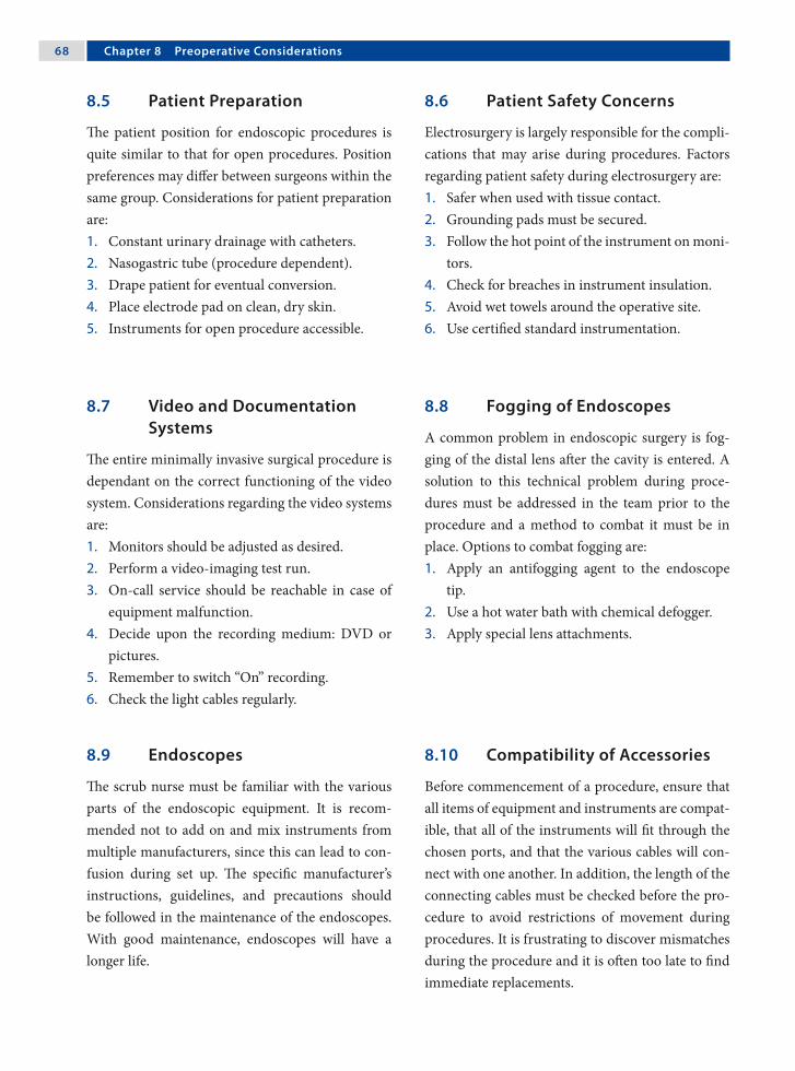
�� Chapter � Preoperative Considerations
8.5 Patient Preparation
The patient position for endoscopic procedures is quite similar to that for open procedures. Position preferences may differ between surgeons within the same group. Considerations for patient preparation are:1. Constant urinary drainage with catheters.2. Nasogastric tube (procedure dependent).3. Drape patient for eventual conversion.4. Place electrode pad on clean, dry skin.5. Instruments for open procedure accessible.
8.6 Patient Safety Concerns
Electrosurgery is largely responsible for the compli-cations that may arise during procedures. Factors regarding patient safety during electrosurgery are:1. Safer when used with tissue contact.2. Grounding pads must be secured.3. Follow the hot point of the instrument on moni-
tors.4. Check for breaches in instrument insulation.5. Avoid wet towels around the operative site.6. Use certified standard instrumentation.
8.7 Video and Documentation Systems
The entire minimally invasive surgical procedure is dependant on the correct functioning of the video system. Considerations regarding the video systems are:1. Monitors should be adjusted as desired.2. Perform a video-imaging test run.3. On-call service should be reachable in case of
equipment malfunction.4. Decide upon the recording medium: DVD or
pictures.5. Remember to switch “On” recording.6. Check the light cables regularly.
8.8 Fogging of Endoscopes
A common problem in endoscopic surgery is fog-ging of the distal lens after the cavity is entered. A solution to this technical problem during proce-dures must be addressed in the team prior to the procedure and a method to combat it must be in place. Options to combat fogging are:1. Apply an antifogging agent to the endoscope
tip.2. Use a hot water bath with chemical defogger.3. Apply special lens attachments.
8.9 Endoscopes
The scrub nurse must be familiar with the various parts of the endoscopic equipment. It is recom-mended not to add on and mix instruments from multiple manufacturers, since this can lead to con-fusion during set up. The specific manufacturer’s instructions, guidelines, and precautions should be followed in the maintenance of the endoscopes. With good maintenance, endoscopes will have a longer life.
8.10 Compatibility of Accessories
Before commencement of a procedure, ensure that all items of equipment and instruments are compat-ible, that all of the instruments will fit through the chosen ports, and that the various cables will con-nect with one another. In addition, the length of the connecting cables must be checked before the pro-cedure to avoid restrictions of movement during procedures. It is frustrating to discover mismatches during the procedure and it is often too late to find immediate replacements.

Amulya K. Saxena ��
Recommended Literature
1. Chan SW, Hensman C, Waxman BP, Blamey S, Cox J, Farrell K, Fox J, Gribbin J, Layani L (2002) Technical developments and a team approach leads to an im-proved outcome: lessons learnt implementing laparo-scopic splenectomy. ANZ J Surg 72:523–527
2. Hsiao KC, Machaidze Z, Pattaras JG (2004) Time man-agement in the operating room: an analysis of the dedi-cated minimally invasive surgery suite. JSLS 8:300–303
3. Ohdaira T, Nagai H, S. Kayano S, Kazuhito H (2007) Antifogging effects of a socket-type device with the su-perhydrophilic, titanium dioxide-coated glass for the laparoscope. Surg Endosc 21:333–338
8.11 Lasers in Endoscopic Surgery
Application of laser technology in endoscopic sur-gery has gained acceptance in a wide variety of pro-cedures. Protective personnel precautions should be employed if the laser is used in endoscopic surgery, although the risk of retinal damage is much lower than in open surgical procedures. Signs should be posted outside the operating room door indicat-ing the use of a laser. In addition, a suitable suction device should be present to properly evacuate the laser plume during procedures.
8.12 Preparation and Draping
Before placing the patient on the surgical table, the anesthetist may prefer that a warming blanket be applied below the table sheet, especially in infants and small children. For endoscopic procedures, the patient is prepped and draped in the same rou-tine fashion as for open procedures, but all draping must be performed in a commonsense manner, tak-ing into account the specific procedure being per-formed.

9.1 Assortment and Definition of Ports
1. Insufflation port: used for carbon dioxide (CO2) insufflation. This is the first port placed during a procedure and could be either a Veress needle or a combined port.
2. Optical port: this is used for camera introduc-tion.
3. Work port: this is used for introduction of the instruments.
4. Combined port: port with a valve for CO2 insuf-flation that can simultaneously be used for the camera, instruments, or both.
9.2 Main Access Techniques
1. Closed access: the closed technique is performed by the insertion of a Veress needle through the immediate subumbilical area in a previously unoperated abdomen.
2. Open access: access is gained into the cavities using open surgical methods with placements of ports under complete vision.
9.3 Umbilical Access Sites
Abdominal access through the umbilicus can be achieved through either (a) superior or inferior umbilical crease incision, (b) lateral umbilical fold incision or (c) directly transumbilical.
The advantages of umbilical access are:1. Thinnest part of abdominal wall.2. Center point of the abdomen for the best over-
view.3. No major blood vessels present.4. Good cosmetic results of scar concealment.
9.4 Trocar and Veress Needle Injuries
Open establishment of a pneumoperitoneum is safer compared to the closed (Veress-needle) tech-nique. Injuries to the small bowel, bladder or ves-sels may occur in closed techniques due to forceful insertion of the trocars. In pediatric laparoscopic surgery the open-access technique is preferred and accepted at most centers worldwide.
9 Closed- and Open-Access TechniquesJohannes Schalamon

�2 Chapter � Closed- and Open-Access Techniques
9.5 Veress Needle Insertion
1. A stab incision is made in the umbilical fold.2. The abdominal wall is elevated.3. The Veress needle is held like a dart between the
fingers and inserted at an angle of 45° to the ab-dominal wall.
4. The “hanging-drop” test is performed to con-firm the free location of the Veress needle tip.
5. Gas is insufflated through the Veress needle to create a cushion over the bowel for insertion of the primary trocar.
9.6 Removal of the Ports
1. Removal of ports under vision is recommended to avoid omental incarceration.
2. Closure of large access wounds in layers to pre-vent port-hernia.
3. Absorbable sutures are preferred for closure of port sites.
4. Remove infected tissue using specimen retrieval bags to prevent contamination of the port sites.
9.7 Closed Abdominal Access Using a Veress Needle
Please see Figs. 1–4.
Figure 9.2
A definitive “click” is felt in the hand as the nee-dle enters the abdominal cavity. The needle is then moved side to side and its freedom is assessed to ensure that the inserted tip is free inside the peri-toneal cavity
Figure 9.1
The abdomen is grasped and raised with clamp(s) to produce counter traction against the needle and allow the intestines to fall away from the site of nee-dle insertion. The needle is held like a dart in the middle and inserted at angle of 45° towards the cau-dal part of the abdomen
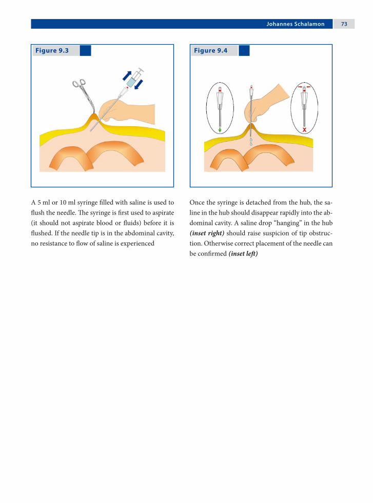
Johannes Schalamon �3
Figure 9.3 Figure 9.4
A 5 ml or 10 ml syringe filled with saline is used to flush the needle. The syringe is first used to aspirate (it should not aspirate blood or fluids) before it is flushed. If the needle tip is in the abdominal cavity, no resistance to flow of saline is experienced
Once the syringe is detached from the hub, the sa-line in the hub should disappear rapidly into the ab-dominal cavity. A saline drop “hanging” in the hub (inset right) should raise suspicion of tip obstruc-tion. Otherwise correct placement of the needle can be confirmed (inset left)

�� Chapter � Closed- and Open-Access Techniques
Figure 9.7 Figure 9.8
9.8 Open Abdominal Access
Please see Figs. 5–10.
Figure 9.5 Figure 9.6
The umbilicus is meticulously cleansed/prepared with Betadine or alcohol
Holding the umbilical fold with forceps under ten-sion the umbilical crease is incised
Blunt preparation through the subcutaneous tissue is done to expose the fascia
The fascia is incised and the peritoneum is identi-fied and opened

Johannes Schalamon ��
Literature Recommended
1. Ballem RV, Rudomanski J (1993) Techniques of pneu-moperitoneum. Surg Laparosc Endosc 3:42–43
2. Schaefer M, Lauper M, Kraehenbuehl L (2001) Tro-car and Veress needle injuries during laparoscopy. Surg Endosc 15:275–280
Figure 9.9 Figure 9.10
3. Zaraca F, Catarci M, Gossetti F, Mulieri G, Carboni M (1999) Routine use of open laparoscopy: 1006 consecu-tive cases. J Laparoendosc Adv Surg Tech A 9:75–80
A purse-string suture is placed to secure the edges of the peritoneum and fascia
The purse-string suture is further used to secure the port and to minimize gas leaks. The suture can be tied to close the fascia after completion of the pro-cedure
10.1 Introduction to Video-Assisted Thoracic Surgery
Video-assisted thoracic surgery (VATS) in the pe-diatric population has progressed rapidly since its development in the mid 1970. The indications for VATS in children have become diverse and con-tinue to advance as instrumentation and skills im-prove. VATS procedures offer reduced patient dis-comfort, improved cosmetic outcome, prevention of functional disorders of the chest and shoulder as a result of thoracotomy incisions, and may shorten hospital stays when compared to traditional thora-cotomy.
In this chapter, we will discuss important con-cepts in all VATS procedures, but leave the techni-cal discussion of each specific procedure to other chapters.
10 Concepts in Video-Assisted Thoracic Surgery (VATS)Stephanie P. Acierno and John H.T. Waldhausen

�� Chapter 10 Concepts in Video-Assisted Thoracic Surgery (VATS)
BasicTechniques
Intrathoracic Mediastinum
Diagnosticevaluationofthepleura Pericardialdrainage
Empyemectomy Pericardialwindow
Evacuationofhemothorax Mediastinaltumorbiopsy
Mechanicalorchemicalpleurodesis Mediastinallymphnodebiopsy
Blebresection
Lungbiopsy
Sympathectomy
Transdiaphragmaticliverbiopsy
10.2 Indications for VATS
AdvancedTechniques
Intrathoracic Mediastinum
Evaluationoftrauma(diaphragm) Vagotomy
Decortication Thoracicductligation
Lobectomy Patentductusarteriosusligation
Resectionofsequestration Esophagealdissection
Diaphragmaticplication Esophagealmyotomy
Congenitaldiaphragmaticherniarepair Esophagealatresiarepair
Anteriorspineprocedures Tracheoesophagealfistulaligation
Bronchogeniccystsurgery
Neurogenictumorresection
Benignesophagealtumorresection
Aortopexy
Thymectomy
Automaticimplantablecardioverterdefibrillators(AICD)implantation
Stephanie P. Acierno and John H.T. Waldhausen ��
10.4 Anesthesia Considerations
10.4.1 Preoperative Considerations
1. Thorough preoperative evaluation.2. Assess need for blood availability.3. Adequate intravenous access (if central access
needed, place patient on operative side).4. Standard monitoring as indicated by patient
condition and specific procedure.5. Recommended to be performed under general
anesthetic to ensure adequate pain and airway control.
10.4.2 Double-Lung Ventilation Option
If the double-lung ventilation option is chosen, the following may allow adequate visibility:1. Introduction of pneumothorax with spontan-
eous ventilation.2. Insufflation of carbon dioxide (CO2) into the
thoracic cavity (low pressures 4–8 mmHg).3. Use of retractors (will require an additional 3-,
5-, or 10-mm access site).4. Fan (5 or 10 mm) or snake (3 mm) retractors
can be placed into the chest without a port.
10.3 Contraindications
10.3.1 Absolute Contraindications
The only absolute contraindications are conditions that prevent adequate visualization of the thoracic space such as:1. Pleural symphysis.2. Inability to tolerate single lung ventilation.3. Contralateral pneumonectomy.4. High positive-pressure ventilation.
10.3.2 Relative Contraindications
These do not eliminate VATS as an option, but must be carefully considered in operative planning:1. Prior tube thoracostomy.2. Previous thoracoscopy or thoracotomy.3. Coagulopathy (if uncorrectable, is absolute con-
traindication).

�0 Chapter 10 Concepts in Video-Assisted Thoracic Surgery (VATS)
10.4.3 Single-Lung Ventilation Option – I
Dual-lumen endotracheal tubes:1. Only widely available for patients older than
8 years of age (size 26 Fr).2. Offers easy conversion from single- to double-
lung ventilation if the need arises.
Figure 10.1
Bronchial blocker method of single-lung ventila-tion
10.4.4 Single-Lung Ventilation Option – II
Bronchial blockers (Fig. 1):1. Under bronchoscopic guidance, pass a Fog-
arty catheter or Swan-Ganz catheter into the in-volved side.
2. Inflate the balloon to occlude the desired side (Swan-Ganz allows oxygen delivery to the in-volved side to facilitate oxygenation if needed).
3. The noncuffed endotracheal tube can remain in the trachea or be advanced into the contralat-eral lung.
4. The Fogarty catheter may become dislodged during the procedure and obstruct the endo-tracheal tube, and so requires continuous moni-toring of breath sounds and compliance.
10.4.5 Single-Lung Ventilation Option – III
Selective endobronchial intubation can be per-formed blindly for right-sided intubation, but may require bronchoscopy or fluoroscopy for left-sided placement1. Use a cuffed endotracheal tube 0.5–1 size
smaller than usual.2. The balloon is inflated to prevent ventilation of
the opposite lung.3. May become dislodged with positioning or bal-
loon inflation.

Stephanie P. Acierno and John H.T. Waldhausen �1
10.5.1 Preoperative Imaging
1. Thorough preoperative imaging will help with planning patient positioning and access sites in order to provide the best access to the lesion.
2. A chest-computed tomography (CT) is most helpful for masses and infiltrates.
3. Ultrasound can be used to find the largest fluid collection in cases of empyema.
4. For spontaneous pneumothoracies, anterior-posterior/lateral X-ray is usually adequate, al-though chest-CT may help identify blebs.
10.5 Technical Considerations for VATS
10.5.2 Positioning of the Patient
Proper positioning will assist with the retraction of uninvolved structures. Using the kidney rest in larger children or a rolled up blanket or foam pad placed under the flank on the dependent side will help mobilize the hip out of the way and open the intercostal spaces.
The positioning of the patient described herein are general guidelines only; they may need to be ad-justed based on the specific lesion, patient size, or surgeon preference.
Patient positioning for the procedures of lung biopsy for diffuse process, anterior lesions (anterior, right middle lobe, or lingual), and posterior lesions are shown in Figs. 2–4.
Figure 10.2
Patient positioning for lung biopsy for diffuse pro-cess. Full lateral decubitus position with operative side up. Lesions on the surface of the lung can be seen directly and the procedures can be performed accordingly (inset)

�2 Chapter 10 Concepts in Video-Assisted Thoracic Surgery (VATS)
Figure 10.3 Figure 10.4
Patient positioning for anterior lesions. Lateral de-cubitus position, operative side up, tilted 30° pos-teriorly. This will allow gravity to retract the lung posteriorly, providing better visibility. The Tren-delenburg or reverse Trendelenburg position will provide improved access to the base or apex, re-spectively (inset)
Patient position for posterior lesions. Lateral decu-bitus position, operative side up, tilted 30° anteri-orly. This will allow gravity to retract the lung an-teriorly, providing better visibility. The Trendelen-burg or reverse Trendelenburg position will provide improved access to the base or apex, respectively (inset)
10.5.3 Access to Mediastinal Lesions
1. Select the side that provides the easiest access to the lesion.
2. Position as previously described to allow the lung to fall away from the lesion with gravity (usually tilted 30° posteriorly for an anterior mass and 30° anteriorly for a posterior mass, as positioned for intrathoracic lesions).
3. Approach these lesions transpleurally. Extra-pleural techniques have not yet been fully devel-oped.
10.5.4 Access to the Diaphragm
1. Lateral decubitus, operative side up. Anterior tilt for posterior lesions, posterior tilt for ante-rior lesions.
2. For plications, the patient should be in the full decubitus position.
3. Morgagni hernias are best approached via the abdomen.

Stephanie P. Acierno and John H.T. Waldhausen �3
10.6 Basic Instrumentation
1. High-intensity light source.2. CO2 insufflator.3. High-resolution video monitors.4. 2.7- or 5-mm telescope. The 5-mm scope is most
commonly used as it provides greater flexibil-ity in the costal interspace to allow a wide rage of camera movement. The 2.7-mm telescope is used in neonates and infants.
5. In larger children (> 8 years old) a 10-mm cam-era can be used, but is rarely necessary.
6. Generally 0° or 30° scopes are most commonly used, but 45–70° scopes may be helpful to im-prove visibility.
7. Camera.8. Basic endoscopic instrument set (3 or 5 mm,
shorter shafts will provide better intrathoracic tissue handling).a. Biopsy forceps.b. Irrigator/aspirator/cautery device.c. Grasper.d. Dissectors.e. Needle holder.f. Scissors.
9. Clip applier (5 mm size)
Other instruments that may be used:1. Specimen retrieval bag.2. Harmonic scalpel.3. LigaSure™ (Valleylab, Boulder, CO, USA).4. Endoscopic ultrasound.5. Argon beam coagulator.6. Automated tissue morcellator.7. Endoscopic stapler: will need 12 mm access and
at least 5 cm within the chest to allow the anvil to open. Therefore, the port must be placed low
in the chest and often can not be used in chil-dren <5 years old. The endoscopic stapler is of-ten passed directly into the chest without a port. Use 2.5- or 3.5-mm staple loads depending on patient size.
8. Cannulas or ports (3, 5, 10, 12 mm). Most often one will be utilized for the camera and two for operating. Thoracoports or laparoscopic ports can be used. The initial port (often the camera port) is placed using a direct cut down.
9. The positioning of the camera port will de-pend on the location of the target lesion and the child’s body habitus; the camera must be placed far enough from the lesion to allow visualiza-tion of the lesion and the working instruments.
As a general guide, camera ports will usually be placed:1. In the 4th or 5th intercostal space at the anterior
axillary line for apex or pleural dome lesions.2. In the 4th or 5th intercostal space, but more lat-
erally for anterior pulmonary or superior medi-astinal lesions.
3. In the 5th or 6th intercostal space at the mid-axillary line for pericardial lesions.
4. In the 5th or 6th intercostal space slightly poster-ior to the midaxillary line for anterior mediasti-nal or hilar lesions.
5. In the 5th or 6th intercostal space slightly ante-rior to the midaxillary line for posterior medi-astinal lesions.
The remaining cannulas should be placed under di-rect vision with the position determined after direct examination of the lesion and the chest cavity.

�� Chapter 10 Concepts in Video-Assisted Thoracic Surgery (VATS)
A configuration of cannulas that will give opti-mal visibility and maneuverability is the baseball di-amond or clock configuration (Fig. 5). Placing the lesion at second base (12 noon), the camera port is placed at home plate (6 o’clock), and the two oper-ating (work) ports are placed at first and third base (3 and 9 o’clock, respectively).
Ports or cannulas are not always required. Most instruments can be passed directly into the chest through an incision, even if insufflation is being used via a single port to help with lung retraction.
With selective intubation, the diaphragm may rise to the 3rd or 4th intercostal space, so care must be taken to avoid injury to the diaphragm or subdia-phragmatic organs. Avoid the area 1–2 cm from the sternal margin where the internal mammary arter-ies run.
Port sizes should be chosen based on the size of the instruments that are required. A 10- or 12-mm port should only be used if dictated by equipment size. Careful planning and positioning may allow one to use smaller ports.
Figure 10.5
Baseball diamond or clock-face positioning of the camera and working ports to allow ergonomically appro-priate positioning

Stephanie P. Acierno and John H.T. Waldhausen ��
Recommended Literature
1. Lobe TE, Schropp KP (eds) (1994) Pediatric Laparos-copy and Thoracoscopy. Chapters 6, 9, 10, Saunders, Philadelphia
2. Rodgers BM (2003) The role of thoracoscopy in pedi-atric surgical practice. Semin Pediatr Surg 12:62–70
3. Rothenberg SS (2005) Thoracoscopy in infants and children: the state of the art. J Pediatr Surg 40:303–306
10.7 Use of a Chest Tube Postoperatively
1. Chest tube can be placed under direct vision via one of the port sites, if necessary.
2. If a mediastinal mass or pleural lesion has been biopsied, a red rubber catheter can be used to evacuate any residual pneumothorax after wound closure, and then immediately removed.
3. Some surgeons may omit the chest tube if a sur-gical stapler is used in the parenchymal resec-tion as long as prolonged mechanical ventila-tion is not necessary and no air leak is seen at the staple line on inflation.
4. If a chest tube is placed, it can be removed once the pneumothorax resolves and there is no air leak (can be as soon as 6–12 h postoperatively).
10.8 Complications of VATS
The majority of VATS complications reported in the literature are mild, but include:1. Recurrent pneumothorax.2. Tension pneumothorax during insufflation or
initial air introduction.3. Hemorrhage from a vessel or lung injury (an
open thoracotomy is rarely required).4. Air or CO2 embolism.5. Injury to the diaphragm or subdiaphragmatic
organs.6. Cardiac fibrillation due to the use of cautery too
close to heart, vagus nerve, or pericardium.7. Elevation of serum CO2 levels.8. Subcutaneous crepitus.9. Organ injury from port or instrument inser-
tion.

Figure 11.1
11.1 Introduction
Since their introduction into clinical practice in the late 1990s, the use of computer-enhanced robotic surgical systems has grown rapidly. Originally con-ceived as a military tool for remote battlefield sur-gery, these systems are now used to enable complex endoscopic surgical procedures in a wide variety of pediatric surgical disciplines.
11.2 The Surgical Robotic System
The da Vinci® Surgical System (Intuitive Surgical, Sunnyvale, CA, USA), currently the primary system used in pediatric surgery is comprised of (Fig. 1):1. The surgeon console, which includes a user in-
terface panel, control handles that direct the ro-botic arms, and a stereoscopic visual display.
2. Patient side cart, which includes a two- to three-armed robot that controls the operative instru-ments, and a video endoscope.
The da Vinci® robotic surgical system comprising of a surgeon’s console and a patient side cart. (Courtesy of Intuitive Surgical, Sunnyvale, CA, USA)
11 Robot-Assisted Pediatric SurgeryVenita Chandra, Sanjeev Dutta and Craig T. Albanese

�� Chapter 11 Robot-Assisted Pediatric Surgery
11.3 Advantages of Robotics in Children
Robotic systems have the ability to overcome some of the limitations of conventional laparoscopy, in-cluding difficulties with dexterity and challenges of two-dimensional optics. Advantages include:1. Improved hand-eye coordination.2. Wristed instruments enabling seven degrees of
freedom (Fig. 2).3. Elimination of the fulcrum effect.4. Tremor filtration.5. Stereoscopic three-dimensional visualization.6. Motion scaling.7. Ergonomic positioning.
Figure 11.2
11.4 Disadvantages of Robotics in Children
1. Loss of force feedback (haptics). Surgeon must rely on visual cues such as tissue compression and blanching to compensate.
2. Complex and time-consuming set up, requiring specially trained operating staff.
3. High initial expense and maintenance costs.4. Limited size and variety of available instrumen-
tation.5. Large size discrepancy between the typical pa-
tient and the overall size of the robotic system.
11.5 Anesthetic Considerations
1. Open communication between the anesthesio-logist and surgeon is essential.
2. Pressure points must be carefully padded, and potential sites of instrument back-end collision identified.
3. Extension tubing may be required for intrave-nous and arterial lines.
4. The operating team must practice the crisis sce-nario of undocking the robotic equipment and gaining access to the patient rapidly, should the need arise.
Demonstration of the seven degrees of freedom with a “wristed instrument” compared to the surgeon’s hand. (EndoWrist®; Intuitive Surgical) (Courtesy of Intuitive Surgical, Sunnyvale, CA, USA)

Venita Chandra, Sanjeev Dutta and Craig T. Albanese ��
11.6 Preoperative Considerations
1. The robot is usually placed at the head of the bed for upper gastrointestinal and hepatobiliary cases.
2. Elevate the child off the bed on foam and blan-kets to prevent instrument backend collisions with the bed.
3. Ports must be as widely spaced as possible to achieve proper orientation.
11.7 Current Applications in Pediatric Subspecialties
While the majority of clinical experience in robotic surgery is in the field of pediatric general surgery, robot-assisted techniques are being applied to a growing number of surgical subspecialties.
Cardiothoracic applications include ligation of the patent ductus arteriosus and division of vascu-lar rings.
In pediatric urology, robotic assistance is de-scribed for nephrectomy, pyeloplasty, and appendi-covesicostomy.
11.8 Clinical Utility in Pediatric Surgery
1. Robotics is an enabling technology for surgeons not proficient in laparoscopy, allowing them to perform advanced minimal-access procedures they would otherwise do as open procedures.
2. For advanced laparoscopists, robotics does not improve basic dissection; however, it enables the performance of complex tasks (e.g., suturing a portoenterostomy) that require precision in a limited operative field or at awkward angles.
3. Clinical utility in pediatric patients is currently limited by the lack of small instrumentation, high cost, and cumbersome setup.
11.9 Future of Robotic Surgery
The future of robotic surgery lies in its ability to transcend human capability. Emerging develop-ments include high-fidelity force sensors to improve tactile sensation, overlying of imaging data onto the operative field (augmented reality), and device mini-aturization, which will allow surgeons to access re-mote anatomy without extensive dissection and fur-ther apply robotics to neonates and fetuses.

�0 Chapter 11 Robot-Assisted Pediatric Surgery
11.10 Current Applications in Pediatric General Surgery
Robot-assisted endoscopic procedures have been described for cholecystectomy, splenectomy, fundo-plication, the Kasai procedure, choledochal cyst ex-cision, Heller myotomy, posterior mediastinal cyst excision, and subcutaneous giant lipoma excision. In addition, successful formation of an esophago-esophagostomy and treatment of diaphragmatic hernias have been reported in animal studies.
11.11 Conclusion
Robot-assisted surgery holds promise in the pediat-ric population; however, further technical advances must be made and cost must come down for robot-ics to be adopted widely.
Literature Recommended
1. Camarillo DB, Krummel TM, Salisbury JK Jr (2004) Robotic technology in surgery: past, present, and fu-ture. Am J Surg 188:2S–15S
2. Chandra V, Dutta S, Albanese CT (2006) Surgical ro-botics and image guided therapy in pediatric surgery: emerging and converging minimal access technolo-gies. Semin Pediatr Surg 15:267–275
3. Woo R, Le D, Krummel TM, Albanese C (2004) Ro-bot-assisted pediatric surgery. Am J Surg 188:27S–37S
Section 2 Video-Assisted Thoracoscopic Surgery (VATS)

Surgical Team Position
12.1 Operation Room Setup
12 LobectomySteven S. Rothenberg

�� Chapter 12 Lobectomy
12.3 Special Instruments
• LigaSure™ (Valleylab, Boulder, CO, USA)• Endoscopic clip applicator • Endo GIA™ stapler (Auto Suture, Norwalk, CT,
USA)
Port Placement Sites
12.2 Patient Positioning
The patient is placed in a formal lateral decubitus position. The surgeon and assistant are at the front of the patient.
12.4 Location of Access Points

Steven S. Rothenberg ��
12.5 Indications
1. Congenital adenomatoid malformation.2. Pulmonary sequestration.3. Congenital lobar emphysema.4. Severe bronchiectasis.5. Right middle lobe syndrome.6. Cystic fibrosis.
12.6 Contraindications
1. Severe respiratory distress associated with any of the above.
2. Necrotizing pneumonia and sepsis.3. Malignancy.
12.8 Technical Notes
1. Valved ports and carbon dioxide insufflation should be used during the case to aide in lung collapse.
2. If there are large air- or fluid-filled cysts, they should be involuted or drained and decom-pressed to create more intrathoracic space and improve visualization.
3. An anatomic resection should be performed in all cases. Mass blind ligations are unsafe.
4. In general, the dissection should be performed from anterior to posterior. It is difficult to flip the lung thoracoscopically and doing so wastes time and results in increased parenchymal bleeding.
12.7 Preoperative Considerations
1. Patient’s respiratory status: the best chance for success is if the anesthetist can obtain single-lung ventilation of the contralateral side. Pa-tients with significant mass effect or respiratory compromise may not tolerate this.
2. Patient size will determine the vessel and bron-chus ligation technique. The appropriate equip-ment should be available prior to embarking on the procedure.
3. Appropriate antibiotics should be given preop-eratively.
4. If there is a question of abnormal bronchial anatomy, a bronchoscopy should be performed at the beginning of the procedure.
12.9 Procedure Variations
1. Most variation is due to the size of the patient and the lobe being resected. The upper lobe is the most difficult as the main pulmonary artery trunk must be preserved as it courses behind the upper lobe.
2. A hybrid approach instituting a combination of ports and a mini thoracotomy can be used, but this is rarely necessary if the surgeon is famil-iar with the anatomy and has the appropriate in-strumentation.
12.10 Thoracoscopic Lobectomy Procedure
Please see Figs.1–6.
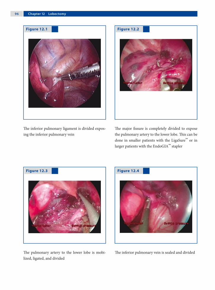
�� Chapter 12 Lobectomy
Figure 12.1
The inferior pulmonary ligament is divided expos-ing the inferior pulmonary vein
The major fissure is completely divided to expose the pulmonary artery to the lower lobe. This can be done in smaller patients with the LigaSure™ or in larger patients with the EndoGIA™ stapler
The pulmonary artery to the lower lobe is mobi-lized, ligated, and divided
The inferior pulmonary vein is sealed and divided
Figure 12.2
Figure 12.3 Figure 12.4

Steven S. Rothenberg ��
Figure 12.6 Figure 12.5
The bronchus is divided and sealed using sutures, clips, or a stapler
The specimen is brought out through the lower port site, which is slightly enlarged
Recommended Literature
1. Albanese CT, Rothenberg SS (2007) Experience with 144 consecutive pediatric thoracoscopic lobectomies. J Laparoendosc Adv Surg Tech 17:339–341
2. Rothenberg SS (2003) Experience with thoracoscopic lobectomy in infants and children. J Pediatr Surg 38:102–104
3. Truitt AK, Carr SR, Cassese J, Kurkchubasche A, Tracy TF Jr, Luks F (2006) Perinatal management of congenital cystic lung lesions in the age of minimally invasive surgery. J Pediatr Surg 41:893–896

13.1 Operation Room Setup
Surgical Team Position
13 Bronchogenic Cyst ResectionRoshni Dasgupta and Richard G. Azizkhan

100 Chapter 13 Bronchogenic Cyst Resection
13.2 Patient Positioning
Ensure the patient is in a semiprone (45°)/lateral decubitus position, with the opposite arm elevated and supported well.
Port Placement Sites
13.3 Special Instruments
1. Ultracision® harmonic scalpel (Johnson & John-son Medical Products Ethicon Endo-Surgery, Cincinnati, OH, USA).
2. LigaSure™(Valleylab, Boulder, CO, USA)
13.4 Location of Access Points

Roshni Dasgupta and Richard G. Azizkhan 101
13.5 Indications
1. Bronchogenic cyst/lesion.2. Resection performed to avoid complications of
a lesion, including infection, hemorrhage, and expansion of cyst.
13.6 Preoperative Considerations
1. Obtain good imaging studies – computed to-mography or magnetic resonance imaging scan of the chest to delineate the location of the bron-chogenic cyst commonly found in the paratra-cheal, perihilar, paraesophageal, and intrapa-renchymal regions.
2. Avoid operation while there is an ongoing in-fection and ensure that the patient is adequately treated prior to attempting resection.
3. Preoperative antibiotics are generally adminis-tered
13.8 Procedure Variations
1. Cyst resection can be performed with the hook cautery, harmonic scalpel, or LigaSure™.
2. Patient positioning and port sites can be varied according to the location of lesion.
3. In paraesophageal lesions perform a swallow study prior to feeding to ensure no leakage of the contrast medium.
4. Most small cysts can be removed from the 5-mm port sites; occasionally an incision may need to be enlarged, or a specimen retrieval bag can be used with a larger port.
13.9 Thoracoscopic Resection of Bronchogenic Cysts
Please see Figs. 1–4.
13.7 Technical Notes
1. Single-lung ventilation is preferred (tube posi-tion is checked using bronchoscopy).
2. Alternatively, insufflate with low pressure at 5–7 mmHg at a low flow rate (1 l/min) to allow for further collapse of the lung. Insufflation should be done slowly to prevent reflex bradycardia.
3. If it appears that vital structures may be com-promised with resection, then it is essential to perform a mucosectomy or fulgurate the mu-cosa with a laparoscopic cautery, or argon beam coagulator to prevent recurrence.
4. Insert a chest tube to evacuate any residual pneu-mothorax, especially for central mediastinal cysts. This can usually be removed within 24 h.

102 Chapter 13 Bronchogenic Cyst Resection
Figure 13.1 Figure 13.2
Figure 13.3 Figure 13.4
Thoracoscopic view of hilar bronchogenic cyst and initial dissection
Dissection of the cyst from the mediastinal attach-ments
The thoracoscopic view of the mediastinum follow-ing removal of the bronchogenic cyst
Histology of the bronchogenic cyst demonstrating a cartilage remnant and ciliated epithelium

Roshni Dasgupta and Richard G. Azizkhan 103
Recommended Literature
1. Engum S (2007) Minimal access thoracic surgery in the pediatric population. Semin Pediatr Surg.15:14–16
2. Mercy C, Spurbeck W, Lobe TE (1999) Resection of foregut derived duplications by minimal access sur-gery. Pediatr Surg Int 15:224–226
3. Ure BM, Schmidt AI, Jesch NK (2005) Thoracoscopic surgery in infants and children. Eur J Pediatr Surg 15:314–318

14.1 Operation Room Setup
Surgical Team Position
14 Resection of Pulmonary SequestrationsLutz Stroedter

10� Chapter 1� Resection of Pulmonary Sequestrations
Port Placement Sites
XX
X
Optic port 5 mm
Work port (5 / 10 mm)*
*Port size depends onthe age of the patient
(X)
14.4 Location of Access Points
14.2 Patient Positioning
The patient is placed in a formal lateral decubitus position. The arm is elevated to move the scapula upward.
14.3 Special Instruments
• Endoscopic clips• Endoscopic stapler• Specimen retrieval bag (10 mm port)

Lutz Stroedter 10�
14.5 Indications
1. The resection of pulmonary sequestrations should be performed within the first year of life (when detected) because of the complications due to risk of infection.
2. Intralobar sequestrations (ILS) have a 9-fold higher risk of infection than extralobar seques-trations (ELS).
3. Most of the ELS lesions are diagnosed coinci-dentally during imaging investigations for sur-gery or for associated congenital anomalies.
14.6 Contraindications
1. General contraindications to Video-Assisted Thoracoscopic Surgery (VATS)
2. Since ELS patients have associated anomalies more frequently than ILS patients; the severity of these anomalies may be relative contraindica-tions to VATS in ELS patients.
14.7 Preoperative Considerations
1. It is difficult to distinguish an ILS from ELS us-ing plain films. However, ILS lesions tend to be heterogeneous and are not well defined. ELS masses are usually observed as solid, well de-fined, and retrocardiac.
2. Computed tomography (CT) with contrast or magnetic resonance angiography (MRA) pro-vide valuable information. The arterial supply and venous drainage both should be outlined because of the unpredictability of vascular con-nections.
3. Upper gastrointestinal contrast examination may be useful if communication with the gas-trointestinal tract is in question.
14.8 Technical Notes
1. ELS account for 25% of cases and have their own pleural covering. No tissue separation from lung is required.
2. ILS are surrounded by normal lung tissue and require endoscopic staplers utilization for surgi-cal resection.
3. Both ELS and ILS receive their blood supply from anomalous systemic arteries, usually aris-ing from the descending aorta.
4. Venous drainage is usually by the pulmonary veins for ILS and by the systemic venous system for ELS.
5. Multiple supply arteries are found in 15% of se-questrations; 73% originating from the abdomi-nal aorta and 18% from the thoracic aorta.
14.9 Procedure Variations
1. The systemic artery can be ligated using three absorbable sutures and intracorporeal suturing.
2. Use of LigaSure™ (Valleylab, Boulder, CO, USA) for abberant vessels up to 7mm in diameter.
3. In ILS, lobectomy or wedge resection can be performed using bipolar cautery or harmonic scalpel.
14.10 Thoracoscopic Resection of Intralobar Sequestrations
Please see Figs. 1–6.

10� Chapter 1� Resection of Pulmonary Sequestrations
Figure 14.1
View of the left thoracic cavity showing the aber-rant vessel as it enters the thorax through the dia-phragm to provide vascular supply to the seques-tration
Figure 14.2
Figure 14.3 Figure 14.4
The lung is retracted using a retractor and the vessel feeding the ILS is carefully clamped using blunt for-ceps to confirm blanching of the sequestration
The feeding vessel is clipped twice centrally and once peripherally using endoscopic titanium clips and dissected. The disruption of vascular supply leads to visible demarcation of the ILS from the normal lung tissue
The endoscopic stapler is used to resect the seques-tration from the normal lung tissue at the plane of demarcation. Multiple staplers may be required de-pending on the size of the sequester

Lutz Stroedter 10�
Recommended Literature
1. Albanese CT, Sydorak AM, Tsao K, Lee H (2003) Tho-racoscopic lobectomy for prenatally diagnosed lung le-sions. J Pediatr Surg 38:553–555
2. de Lagausie P, Bonnard A, Berrebi D, Petit P, Dorg-eret S, Guys JM (2005) Video-assisted thoracoscopic surgery for pulmonary sequestration in children. Ann Thorac Surg 80:1266–1269
3. Rothenberg SS (2008) First decade’s experience with thoracoscopic lobectomy in infants and children. J Pediatr Surg 43:40–44
Figure 14.5 Figure 14.6
A specimen retrieval bag is used to retrieve the se-questration. The port incision is enlarged to extract the specimen out of the thoracic cavity
View of the ILS specimen resected using endo-scopic staplers, along with the clipped supplying vessel (arrow)

15.1 Operation Room Setup
Surgical Team Position
15 Treatment of Pulmonary Blebs and BullaeAmulya K. Saxena

112 Chapter 1� Treatment of Pulmonary Blebs and Bullae
Port Placement Sites
15.4 Location of Access Points
15.2 Patient Positioning
The patient is placed in a formal lateral decubitus position. The surgeon and assistant are at the back of the patient.
15.3 Special Instruments
• LigaSure™ (Valleylab, Boulder, CO, USA)• Endo GIA™ stapler (Auto Suture, Norwalk, CT,
USA)• Laser• PleuraSeal™ lung sealant (Covidien, Hazelwood,
MO, USA)• Fibrin glue

Amulya K. Saxena 113
15.5 Indications
1. Blebs are small 1- to 2-cm subpleural air spaces that a frequently present on the apices of nor-mal lungs.
2. Bullae are relatively large air-filled spaces that arise in the apices of the upper lobes and the su-perior segment of the lower lobes.
3. Indications for thoracoscopic treatment are lim-ited to recurrent disease or episodes that last for 5 days or longer.
15.6 Contraindications
General contraindications to Video-Assisted Tho-racoscopic Surgery (VATS)
15.7 Preoperative Considerations
1. Preoperative assessment with computed tomo-graphy scan should be performed to determine the size and location of the blebs.
2. The type of technique employed determines the number and size of ports used.
3. If endostapler devices are to be employed, ports of 10- or 12-mm should be used.
4. The surgeon must coordinate with the anesthe-tist and make sure that the concentration of oxy-gen being delivered to the lungs is less than 50%, since higher concentrations involve a danger of combustion with serious pulmonary burns.
15.8 Technical Notes
1. The entire lung should be inspected for air leaks.
2. Stapling must be performed with caution to pre-vent bleeding or removal of excess tissue.
3. On completion of the procedure ensure that there are no air leaks by irrigating the thorax and observing bubbles within the fluid.
4. PleuraSeal™ can be applied uniformly as a spray using the endoscopic spray applicator (Micro-Myst™; Covidien, Hazelwood, MO, USA). The lung sealant hydrolyzes over a period of 4 to 8 weeks which gives sufficient time to allow for normal wound healing.
15.9 Procedure Variations
1. Lung tissue division and sealing using endo-scopic linear stapler.
2. Lung tissue resection using LigaSure™. 3. Thoracoscopic ablation using Nd:YAG laser.4. Tissue ligation using standard endoscopic loop
suture.5. Lesion sealing with fibrin glue.6. Chemical pleurodesis by mechanical abrasion.
15.10 Thoracoscopic Options for Pulmonary Blebs and Bullae
Please see Figs. 1–5.
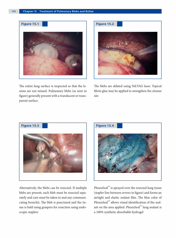
11� Chapter 1� Treatment of Pulmonary Blebs and Bullae
The entire lung surface is inspected so that the le-sions are not missed. Pulmonary blebs (as seen in figure) generally present with a translucent or trans-parent surface
Figure 15.1 Figure 15.2
Figure 15.3 Figure 15.4
The blebs are ablated using Nd:YAG laser. Topical fibrin glue may be applied to strengthen the closure site
Alternatively, the blebs can be resected. If multiple blebs are present, each bleb must be resected sepa-rately and care must be taken to seal any communi-cating bronchii. The bleb is punctured and the tis-sue is held using graspers for resection using endo-scopic staplers
PleuraSeal™ is sprayed over the resected lung tissue (stapler line between arrows in figure) and forms an airtight and elastic sealant film. The blue color of PleuraSeal™ allows visual identification of the seal-ant on the area applied. PleuraSeal™ lung sealant is a 100% synthetic absorbable hydrogel
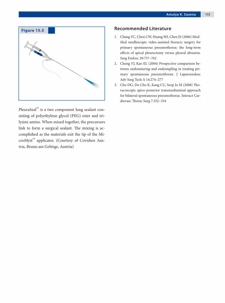
Amulya K. Saxena 11�
Recommended Literature
1. Chang YC, Chen CW, Huang SH, Chen JS (2006) Mod-ified needlescopic video-assisted thoracic surgery for primary spontaneous pneumothorax: the long-term effects of apical pleurectomy versus pleural abrasion. Surg Endosc 20:757–762
2. Cheng YJ, Kao EL (2004) Prospective comparison be-tween endosuturing and endostapling in treating pri-mary spontaneous pneumothorax. J Laparoendosc Adv Surg Tech A 14:274–277
3. Cho DG, Do Cho K, Kang CU, Seop Jo M (2008) Tho-racoscopic apico-posterior transmediastinal approach for bilateral spontaneous pneumothorax. Interact Car-diovasc Thorac Surg 7:352–354
Figure 15.5
PleuraSeal™ is a two component lung sealant con-sisting of polyethylene glycol (PEG) ester and tri-lysine amine. When mixed together, the precursors link to form a surgical sealant. The mixing is ac-complished as the materials exit the tip of the Mi-croMyst™ applicator. (Courtesy of Covidien Aus-tria, Brunn am Gebirge, Austria)
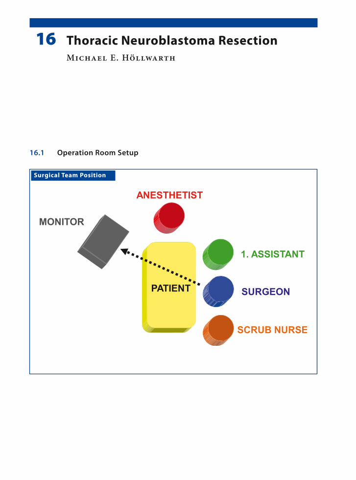
16.1 Operation Room Setup
Surgical Team Position
16 Thoracic Neuroblastoma ResectionMichael E. Höllwarth

11� Chapter 1� Thoracic Neuroblastoma Resection
Port Placement Sites
Work port (5 / 10 mm)
*Port size depends onthe age of the patient
XX
X
Optic port (5 / 10 mm)*
*
16.4 Location of Access Points
16.2 Patient Positioning
The patient is placed in a formal lateral decubitus or modified prone position. The surgeon and the assis-tant stand in front of the patient.
16.3 Special Instruments
• Specimen retrieval bag• Bipolar electrocautery devices• LigaSure™ (Valleylab, Boulder, CO, USA)
Michael E. Höllwarth 11�
16.5 Indications
1. Localized neuroblastoma in Stage 1 accord-ing to the International Neuroblastoma Staging System (INSS) with sizes < 10 cm.
2. The primary goals of surgery are to:a) Determine an accurate diagnosis.b) Remove all of the primary tumor.c) To provide accurate surgical staging. d) Offer adjuvant therapy for delayed primary
surgery.
16.6 Contraindications
1. Diffuse neuroblastoma Stage 3, Stage 4 and Stage 4S (INSS).
2. Tumor mass with involvement of vital struc-tures.
3. Large neuroblastomas > 10 cm.
16.7 Preoperative Considerations
1. Preoperative assessment with computed tomog-raphy should be performed to determine the size and the location of the neuroblastoma in the thorax.
2. Specific investigations to stage neuroblastoma include (1) bone marrow aspirates and biopsy samples, (2) body CT scan (excluding head, if not clinically indicated), (3) bone scan, and (4) meta-iodobenzylguanidine (MIBG) scintigra-phy.
3. Conventional mechanical ventilation with trac-tion of the lung or single-lung ventilation options should be coordinated with the anesthetist.
16.8 Technical Notes
1. Apical tumors must be submitted to traction to allow proper dissected; this could result in tem-porary sympathetic lesions such as Horner’s syndrome.
2. Precaution should be taken with electrocau-tery, since electrocoagulation associated lateral spread of current or heat could also induce tem-porary Horner’s syndrome.
3. Roots of neurogenic tumors are easy to individ-ualize and excessive traction should be avoided to prevent stretching of the medullar roots. The medullar roots can be divided at the neural fo-ramen using harmonic scalpel.
16.9 Procedure Variations
1. Tumor resection using harmonic scalpel. This has the advantage of reduced thermal spread which decreases complications that are associ-ated with electrosurgery.
2. Port number (3-, 4- or 5- ports) may vary de-pending on the age of the patient, size of the tu-mor, type of ventilation and location of the tu-mor.
16.10 Thoracoscopic Resection of Neuroblastoma
Please see Figs. 1–6.

120 Chapter 1� Thoracic Neuroblastoma Resection
Figure 16.1 Figure 16.2
Figure 16.4 Figure 16.3
Nonenhanced axial CT scan of the chest in a patient with a thoracic neuroblastoma showing a right pos-terior mediastinal mass (arrow)
Endoscopic view of the thoracic neuroblastoma covered by the parietal pluera
Using bipolar electrocautery scissors the parietal pleura covering the neuroblastoma is incised
Further preparation of the neuroblastoma is car-ried out using a combination of bipolar electrocau-tery scissors and blunt dissection. The short inter-costal vessels supplying the tumor have to be care-fully cauterized
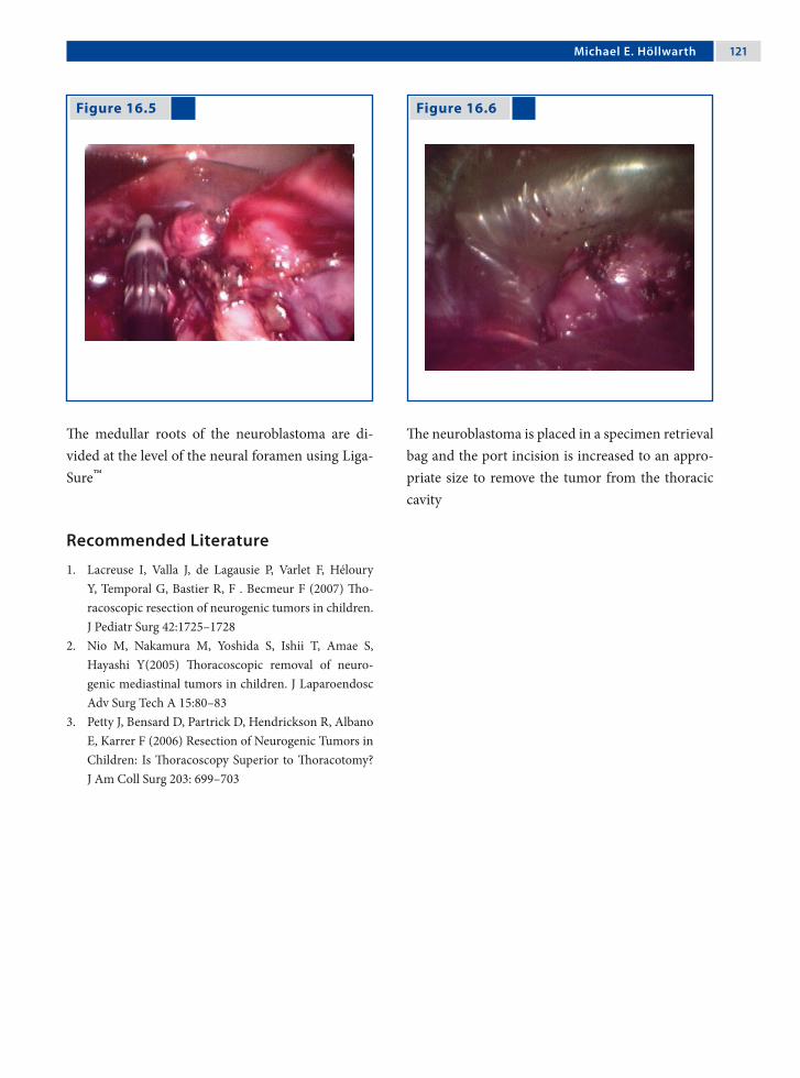
Michael E. Höllwarth 121
Recommended Literature
1. Lacreuse I, Valla J, de Lagausie P, Varlet F, Héloury Y, Temporal G, Bastier R, F . Becmeur F (2007) Tho-racoscopic resection of neurogenic tumors in children. J Pediatr Surg 42:1725–1728
2. Nio M, Nakamura M, Yoshida S, Ishii T, Amae S, Hayashi Y(2005) Thoracoscopic removal of neuro-genic mediastinal tumors in children. J Laparoendosc Adv Surg Tech A 15:80–83
3. Petty J, Bensard D, Partrick D, Hendrickson R, Albano E, Karrer F (2006) Resection of Neurogenic Tumors in Children: Is Thoracoscopy Superior to Thoracotomy? J Am Coll Surg 203: 699–703
Figure 16.6 Figure 16.5
The medullar roots of the neuroblastoma are di-vided at the level of the neural foramen using Liga-Sure™
The neuroblastoma is placed in a specimen retrieval bag and the port incision is increased to an appro-priate size to remove the tumor from the thoracic cavity
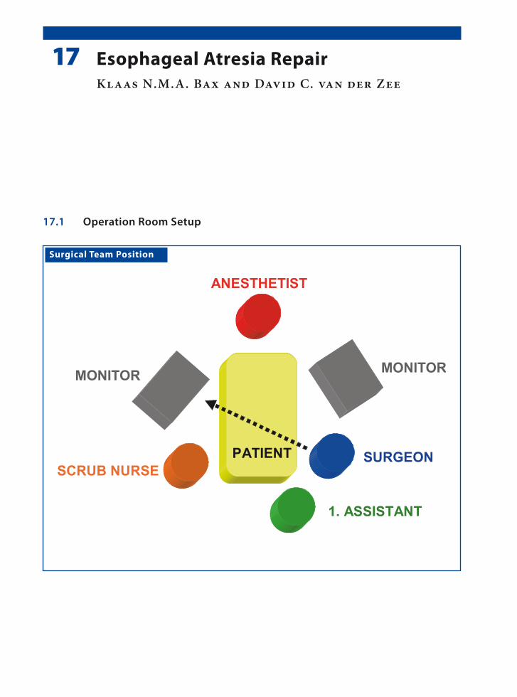
17.1 Operation Room Setup
Surgical Team Position
17 Esophageal Atresia RepairKlaas N.M.A. Bax and David C. van der Zee
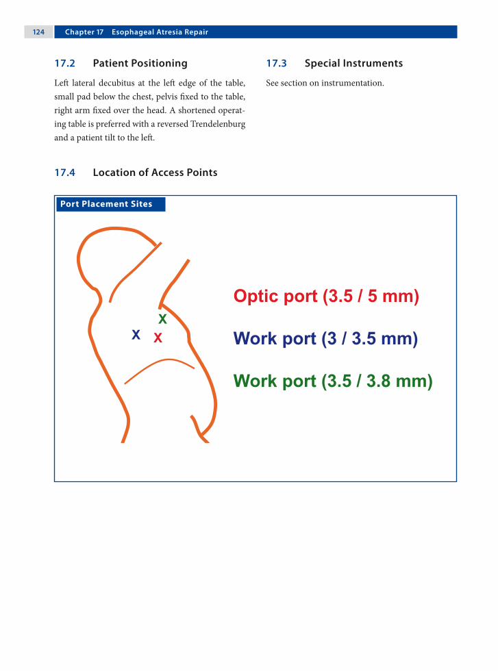
12� Chapter 1� Esophageal Atresia Repair
17.3 Special Instruments
See section on instrumentation.
Port Placement Sites
XXX
Optic port (3.5 / 5 mm)
Work port (3 / 3.5 mm)
Work port (3.5 / 3.8 mm)
17.2 Patient Positioning
Left lateral decubitus at the left edge of the table, small pad below the chest, pelvis fixed to the table, right arm fixed over the head. A shortened operat-ing table is preferred with a reversed Trendelenburg and a patient tilt to the left.
17.4 Location of Access Points
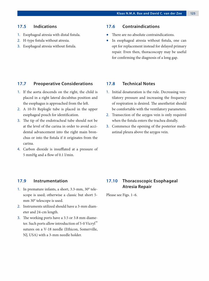
Klaas N.M.A. Bax and David C. van der Zee 12�
17.5 Indications
1. Esophageal atresia with distal fistula.2. H-type fistula without atresia.3. Esophageal atresia without fistula.
17.6 Contraindications
• There are no absolute contraindications. • In esophageal atresia without fistula, one can
opt for replacement instead for delayed primary repair. Even then, thoracoscopy may be useful for confirming the diagnosis of a long gap.
17.7 Preoperative Considerations
1. If the aorta descends on the right, the child is placed in a right lateral decubitus position and the esophagus is approached from the left.
2. A 10-Fr Replogle tube is placed in the upper esophageal pouch for identification.
3. The tip of the endotracheal tube should not be at the level of the carina in order to avoid acci-dental advancement into the right main bron-chus or into the fistula if it originates from the carina.
4. Carbon dioxide is insufflated at a pressure of 5 mmHg and a flow of 0.1 l/min.
17.9 Instrumentation
1. In premature infants, a short, 3.3-mm, 30° tele-scope is used; otherwise a classic but short 5-mm 30° telescope is used.
2. Instruments utilized should have a 3-mm diam-eter and 24-cm length.
3. The working ports have a 3.5 or 3.8 mm diame-ter. Such ports allow introduction of 5-0 Vicryl™ sutures on a V-18 needle (Ethicon, Somerville, NJ, USA) with a 3-mm needle holder.
17.10 Thoracoscopic Esophageal Atresia Repair
Please see Figs. 1–6.
17.8 Technical Notes
1. Initial desaturation is the rule. Decreasing ven-tilatory pressure and increasing the frequency of respiration is desired. The anesthetist should be comfortable with the ventilatory parameters.
2. Transection of the azygos vein is only required when the fistula enters the trachea distally.
3. Commence the opening of the posterior medi-astinal pleura above the azygos vein.

12� Chapter 1� Esophageal Atresia Repair
Figure 17.1 Figure 17.2
Figure 17.3 Figure 17.4
The mediastinal pleura is opened just anterior to the vertebral column
The distal fistula is freed close to the trachea and is suture ligated at this point. It is transected distally and its end is spatulated
The proximal pouch as well as the distal fistula are visualized
The distal end of the proximal pouch is freed and a wide opening is made right in the center

Klaas N.M.A. Bax and David C. van der Zee 12�
Recommended Literature
1. Aziz GA, Schier F (2005) Thoracoscopic ligation of a tracheoesophageal H-type fistula in a newborn. J Pedi-atr Surg 40:e35–36
2. Bax KM, van der Zee DC (2002) Feasibility of thoraco-scopic repair of esophageal atresia with distal fistula. J Pediatr Surg 37:192–196
3. Holcomb GW 3rd, Rothenberg SS, Bax KM, Marti-nez-Ferro M, Albanese CT, Ostlie DJ, van der Zee DC, Yeung CK (2005) Thoracoscopic repair of esophageal atresia and tracheoesophageal fistula: a multi-institu-tional analysis. Ann Surg 242:422–428
Figure 17.5 Figure 17.6
View of the suture-ligated tracheal side of the di-vided distal fistula and the emergence of the Replo-gle from the opened proximal pouch
The anastomosis is started in the middle of the left side of the esophagus and completed using 5-0 ab-sorbable suture (Vicryl™; Ethicon, Somerville, NJ, USA). A transanastomotic 6-Fr or 8-Fr nasogastric tube is left in situ

Surgical Team Position
18.1 Operation Room Setup
18 Congenital Diaphragmatic Hernia RepairFrançois Becmeur
130 Chapter 1� Congenital Diaphragmatic Hernia Repair
18.3 Special Instruments
• Gore-Tex® (WL Gore & Associates, Flagstaff, AZ, USA)
• Patches for large defects
Port Placement Sites
18.2 Patient Positioning
Right lateral decubitus with the left upper extremity left free and supported by the patient’s head to per-mit 360° motion of the ports.
18.4 Location of Access Points
François Becmeur 131
18.5 Indications
1. Delayed congenital diaphragmatic hernia (CDH).
2. Incarcerated diaphragmatic hernia3. CDH in neonates who are stabilized and present
with a small defect.4. Recurrent CDH.
18.6 Contraindications
1. Left-sided CDH with stomach and liver hernia-tion.
2. Right-sided CDH with liver herniation.3. Cardiopulmonary instability.
18.7 Preoperative Considerations
1. In the operating room, each patient receives perioperative antibiotics.
2. An arterial line and adequate intravenous access is established.
3. Pre- and postductal oxygen saturation monitors are placed.
4. Main stem intubation is not required. Patients are ventilated using pediatric ventilators with a pressure-limited mode of ventilation.
18.9 Procedure Variations
1. In case of incarcerated delayed CDH, begin with a thoracoscopic approach.
2. If the hernia contents can not be reduced, con-tinue with a laparoscopic approach (the abdo-men prepped for this eventuality).
3. For the laparoscopic approach (in case of a left CDH), the optic port is passed through the um-bilicus and the work port is placed in the left upper quadrant.
4. When the hernia contents are reduced, revert back to thoracoscopy to suture the diaphrag-matic defect.
18.10 Thoracoscopic Congenital Diaphragmatic Hernia Repair
Please see Figs. 1–14.
18.8 Technical Notes
1. Insufflation is started with low pressure (4 mmHg) and low flow (1.5 l/min).
2. Reduce contents with gentle manipulation.3. Open the peritoneal posterior fold.4. Remove the sac if present.5. The defect is closed from medial to lateral.6. Use nonabsorbable sutures (3-0 or 2-0).7. Apply anchored rib sutures and/or pledgetted
sutures at the lateral side of the defect.8. A chest tube is not required.

132 Chapter 1� Congenital Diaphragmatic Hernia Repair
Figure 18.1 Figure 18.2
Figure 18.3 Figure 18.4
Delayed left congenital diaphragmatic hernia (CDH) presenting with herniation of the left kid-ney covered by a sac
After 5 min of insufflation the contents can be re-duced and the defect repaired
Thoracoscopic view of a delayed left CDH showing the herniated contents covered with a sac
Delayed left CDH with the herniation of the entire spleen in the thoracic cavity

François Becmeur 133
Figure 18.5 Figure 18.6
Figure 18.7 Figure 18.8
Atraumatic graspers are used to gently reduce the herniated contents
Two atraumatic graspers are employed to succes-sively reduce the herniated intestines
After reduction of the herniated contents, the pos-terior flap of the diaphragm is identified to access the possibility of primary repair
Diaphragmatic hernias may occur without the pres-ence of a sac around the defect

13� Chapter 1� Congenital Diaphragmatic Hernia Repair
Figure 18.9 Figure 18.10
Figure 18.11 Figure 18.12
If a sac is present, it is removed by excision using electrosurgical instruments
Primary closure with interrupted sutures is possible when sufficient muscle is present
In large defects, the port site incision is increased to facilitate the insertion of a Gore-Tex® patch
The Gore-Tex® patch is sutured along the brim of the diaphragm using interrupted sutures

François Becmeur 13�
Figure 18.13 Figure 18.14
On completion of the procedure, incisions are closed using skin sutures and Steristrips
Left-sided CDH closure in a neonate. Preoperative (above) and postoperative (below) chest films

13� Chapter 1� Congenital Diaphragmatic Hernia Repair
Recommended Literature
1. Becmeur F, Reinberg O, Dimitriu C, Mooq R, Philippe P (2007) Thoracoscopic repair of congenital dia-phragmatic hernia in children. Semin Pediatr Surg 16:238–244
2. Nguyen TL, Le AD (2006) Thoracoscopic repair for congenital diaphragmatic hernia: lessons from 45 cases. J Pediatr Surg 41:1713–1715
3. Yang EY, Allmendinger M, Johnson SM, Chen C, Wilson JM, Fishman SJ (2005) Neonatal thoracoscopic repair of congenital diaphragmatic hernia: selection criteria for successful outcome. J Pediatr Surg 40:1369–1375

Surgical Team Position
19.1 Operation Room Setup
19 ThymectomyMichael E. Höllwarth

13� Chapter 1� Thymectomy
Port Placement Sites
19.3 Special Instruments
• Ultracision® harmonic scalpel (Johnson & John-son Medical Products, Ethicon Endo-Surgery, Cincinnati, OH, USA)
• Endoscopic clip applicator • Specimen retrieval bag
19.2 Patient Positioning
A 30° right lateral decubitus position.
19.4 Location of Access Points

Michael E. Höllwarth 13�
19.5 Indications
1. Tumors of the thymus gland.2. Myasthenia gravis.3. Nonatrophic thymic glands.4. Thymic cysts.
19.6 Contraindications
1. Neonatal type of myasthenia gravis.2. Caution in immunocompromised and immu-
nosuppressed patients.
19.7 Preoperative Considerations
1. Admit the patient 48 h prior to surgery.2. Pulmonary function tests to recognize impend-
ing respiratory failure due to general muscle weakness.
3. Adjustment of cholinesterase inhibitors and ste-roid if indicated.
4. Chest physiotherapy is started.
19.9 Procedure Variations
1. Video-assisted thoracoscopic thymectomy can be performed through left or right approaches. The left side is preferred.
2. A right-sided approach is preferred in patients with a history of pleurodesis in the left pleural cavity or those with severe cardiomegaly.
19.10 Thoracoscopic Thymectomy
Please see Figs. 1–6.
19.8 Technical Notes
1. Extensive removal of perithymic adipose tissue must be always pursued.
2. Use harmonic scalpel to minimize the risks of electrically induced arrhythmias.
3. Major vascular injuries cannot be controlled thoracoscopically.
4. Care must be taken to avoid phrenic nerve in-jury during dissection of perithymic adipose tis-sue and injury to the left recurrent nerve while dissecting in the aortopulmonary window.
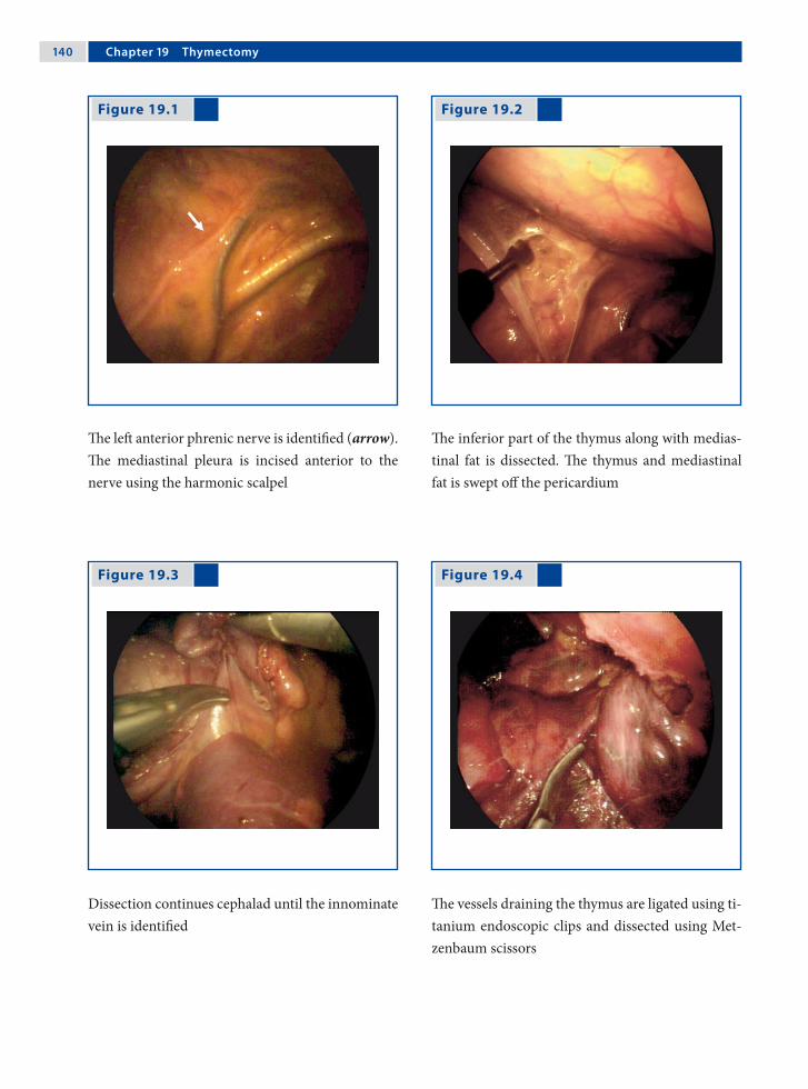
1�0 Chapter 1� Thymectomy
Figure 19.1 Figure 19.2
Figure 19.3 Figure 19.4
The left anterior phrenic nerve is identified (arrow). The mediastinal pleura is incised anterior to the nerve using the harmonic scalpel
The inferior part of the thymus along with medias-tinal fat is dissected. The thymus and mediastinal fat is swept off the pericardium
Dissection continues cephalad until the innominate vein is identified
The vessels draining the thymus are ligated using ti-tanium endoscopic clips and dissected using Met-zenbaum scissors

Michael E. Höllwarth 1�1
Recommended Literature
1. Shiono H, Inoue A, Tomiyama N, Shigemura N, Idegu-chi K, Inoue M, Minami M, Okumura M (2006) Safer video-assisted thoracoscopic thymectomy after loca-tion of thymic veins with multidetector computed to-mography. Surg Endosc 20:1419–1422
2. Tomulescu V, Ion V, Kosa A, Sqarbura O, Popescu I (2006) Thoracoscopic thymectomy mid-term results. Ann Thorac Surg 82:1003–1007
3. Wagner AJ, Cortes R, Strober J, Grethel E, Clifton M, Harrison M, Farmer D, Nobuhara K, Lee H (2006) Long-term follow-up after thymectomy for myasthenia gravis: thoracoscopic vs open. J Pediatr Surg 41:50–54
Figure 19.5 Figure 19.6
All visible fat should be removed as it may contain remnants of thymic tissue. The cranial part of the thymus is retracted into the thorax and dissected free
A specimen retrieval bag is passed through the 10-mm port. The thymus is placed inside the bag and removed from the thorax

Surgical Team Position
20.1 Operation Room Setup
20 AortopexyTimothy D. Kane
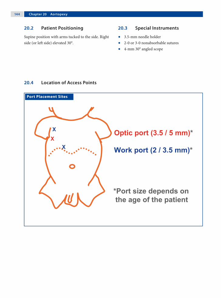
1�� Chapter 20 Aortopexy
20.3 Special Instruments
• 3.5-mm needle holder• 2-0 or 3-0 nonabsorbable sutures• 4-mm 30° angled scope
Port Placement Sites
20.2 Patient Positioning
Supine position with arms tucked to the side. Right side (or left side) elevated 30°.
20.4 Location of Access Points

Timothy D. Kane 1��
20.5 Indications
1. Primary or secondary tracheal compression.2. Aberrant innominate artery takeoff.3. Anterior tracheal compression with “dying
spells” (life-threatening apnea with cyanosis and hypoxia), frequent respiratory infections, stridor, or bradycardia.
20.6 Contraindications
Inability of the patient to tolerate thoracoscopy due to other reasons.
20.7 Preoperative Considerations
1. Assess tracheal compression by magnetic reso-nance imaging or computed tomography scan if necessary.
2. Evaluate and treat gastroesophageal reflux and esophageal strictures in esophageal atresia pa-tients with esophageal dysmotility, which may exacerbate tracheomalacia.
3. Perform preoperative bronchoscopy during spontaneous respiration to document tracheal compression and intraoperative bronchoscopy to document relief of compression (in addition to intraoperative postaortopexy bronchoscopy).
20.9 Procedure Variations
1. A fourth 3.5-mm port may be added for addi-tional exposure or aortic stabilization during su-ture placement.
2. A left-sided thoracoscopic approach can be util-ized with mirror-image placement of port sites to that described for approach from the right.
3. Thymectomy may be required during the left-sided approach.
20.10 Right Thoracoscopic Aortopexy for Tracheomalacia
Please see Figs. 1–9.
20.8 Technical Notes
1. Besides port sites, make a 1-cm incision in the second intercostal space near the sternum.
2. Use 4–6 mmHg of carbon dioxide.3. Dissect the thymus from the aorta.4. Place three or four sutures transsternally via a
sternal incision medial to the mammary vessels. Sutures traverse the pericardium ± aortic adven-titial layer, are passed back out through the ster-num, and tied extracorporeally.

1�� Chapter 20 Aortopexy
Figure 20.1 Figure 20.2
Preoperative bronchoscopic view demonstrating over 50% anterior compression of the trachea by the aorta
Magnetic resonance image reveals midtracheal compression by the aorta and innominate artery

Timothy D. Kane 1��
Figure 20.3 Figure 20.4
Figure 20.5 Figure 20.6
Right thoracoscopic view of the superior vena cava, thymus, retracted right lung, phrenic nerve, and in-ternal mammary vessels (at the top of the picture)
The thymus is mobilized by sharp dissection from the pericardium and aorta
The aorta and overlying pericardium is exposed near the root of the aorta
The first suture is passed into the chest through a parasternal incision, medial to the mammary ves-sels

1�� Chapter 20 Aortopexy
Recommended Literature
1. Corbally MT, Spitz L, Kiely E, Brereton RJ, Drake DP (1993) Aortopexy for tracheomalacia in oesophageal anomalies. Eur J Pediatr Surg 3:264–266
2. Dave S, Currie BG (2006) The role of aortopexy in se-vere tracheomalacia. J Pediatr Surg 41:533–537
3. Schaarschmidt K, Kolberg-Schwerdt A, Pietsch L, Bunke K (2002) Thoracoscopic aortopericardio-sternopexy for severe tracheomalacia in toddlers. J Pe-diatr Surg 37:1476–1478
Figure 20.7 Figure 20.8
Figure 20.9
The suture is passed into the pericardium and ad-ventitial wall of the aorta
The same suture (as in Fig. 7) is passed back through sternum to be tied extracorporeally
Bronchoscopy should be performed to determine whether the number of sutures placed is sufficient. Final thoracoscopic view of the aorta pexied to the undersurface of the sternum after tying all sutures

Surgical Team Position
21.1 Operation Room Setup
21 Closure of a Patent Ductus ArteriosusKari Vanamo

1�0 Chapter 21 Closure of a Patent Ductus Arteriosus
Port Placement Sites
21.3 Special Instruments
• Cotton swabs • Nerve hooks • Dissection hook• Endoscopic clip applicator
21.2 Patient Positioning
Right lateral position with bent table/support under the right chest to open the left intercostals spaces; left shoulder in 90° of flexion and freely movable.
21.4 Location of Access Points

Kari Vanamo 1�1
21.5 Indications
1. Isolated symptomatic patent ductus arteriosus (PDA) after failure of indomethacin treatment.
2. PDA with contraindications to medical therapy.3. Asymptomatic PDA in older infants with the
aim of preventing infective endocarditis.
21.6 Contraindications
1. High-pressure open PDA.2. PDA associated with other congenital heart de-
fects requiring surgery.3. Prematurity or small size (relative contraindica-
tion).4. Inability to withstand lung retraction.
21.8 Technical Notes
1. Single-lung ventilation or carbon dioxide insuf-flation is not used routinely. A fourth incision anteriorly may be required for additional re-traction of the lung to increase visibility.
2. The vagus and recurrent laryngeal nerves should be handled with extreme care and manipulation avoided if possible
3. Two clips are preferred. Inappropriate clip ap-plication could cause injury to the recurrent la-ryngeal nerve or the ductus wall.
4. Chest drain is not necessary; if placed it could be removed once the pleural cavity has been evacuated.
21.9 Procedure Variations
1. Bimanual dissection is feasible. However, this usually requires a fourth incision.
2. In the presence of a large ductus, ligation may be preferred prior to clip application.
3. Monitoring the left laryngeal nerve is feasible and advocated.
4. In older children, transesophageal echocardio-graphy can be utilized to demonstrate the com-plete interruption of ductal flow in real time during the procedure.
21.10 Thoracoscopic Closure of a Patent Ductus Arteriosus
Please see Figs. 1–6.
21.7 Preoperative Considerations
1. Care should be taken to ensure that the clip is in the clip applicator because the empty applicator can act as a pair of scissors if the clip has fallen out.
2. Normothermia and proper attention to venti-lation are imperative, especially in neonatal pa-tients.
3. For PDA repair in the infant, either an operat-ing room or a portable operating room in the neonatal intensive care unit may be sufficient to perform the procedure.

1�2 Chapter 21 Closure of a Patent Ductus Arteriosus
Figure 21.1 Figure 21.2
Figure 21.3 Figure 21.4
The posterior pleura overlying the aorta is incised with an electrocautery hook from the base of the left subclavian artery toward the ductus arteriosus
The medial pleural leaf is retracted with nerve hooks and separated from the aorta using blunt dissection and electrocautery
The upper and lower margins of the duct are dis-sected free, but no attempt is made to circumvent the ductus
The port below the scapular angle is removed and the incision extended bluntly to accommodate the endoscopic clip applicator. The ductus is clipped with one or two metal clips

Kari Vanamo 1�3
Recommended Literature
1. Burke RP, Wernovsky G, van der Velde M, Hansen D, Castaneda A (1995) Video-assisted thoracoscopic sur-gery for congenital heart disease. J Thorac Cardiovasc Surg 109:499–507
2. Laborde F, Noirhomme P, Karam J, Batisse A, Bourel P, Saint Maurice O (1993) A new video-assisted thora-coscopic surgical technique for interruption of patent ductus arteriosus in infants and children. J Thorac Car-diovasc Surg 105:278–280
3. Vanamo K, Berg E, Kokki H, Tikanoja T (2006) Video-assisted thoracoscopic versus open surgery for persis-tent ductus arteriosus. J Pediatr Surg 41:1226–1229
Figure 21.5 Figure 21.6
The field is checked for correct placement of the clip(s) and to rule out bleeding or chylous leak
The pleural cavity is drained, the lung expanded, and the incisions closed with absorbable sutures
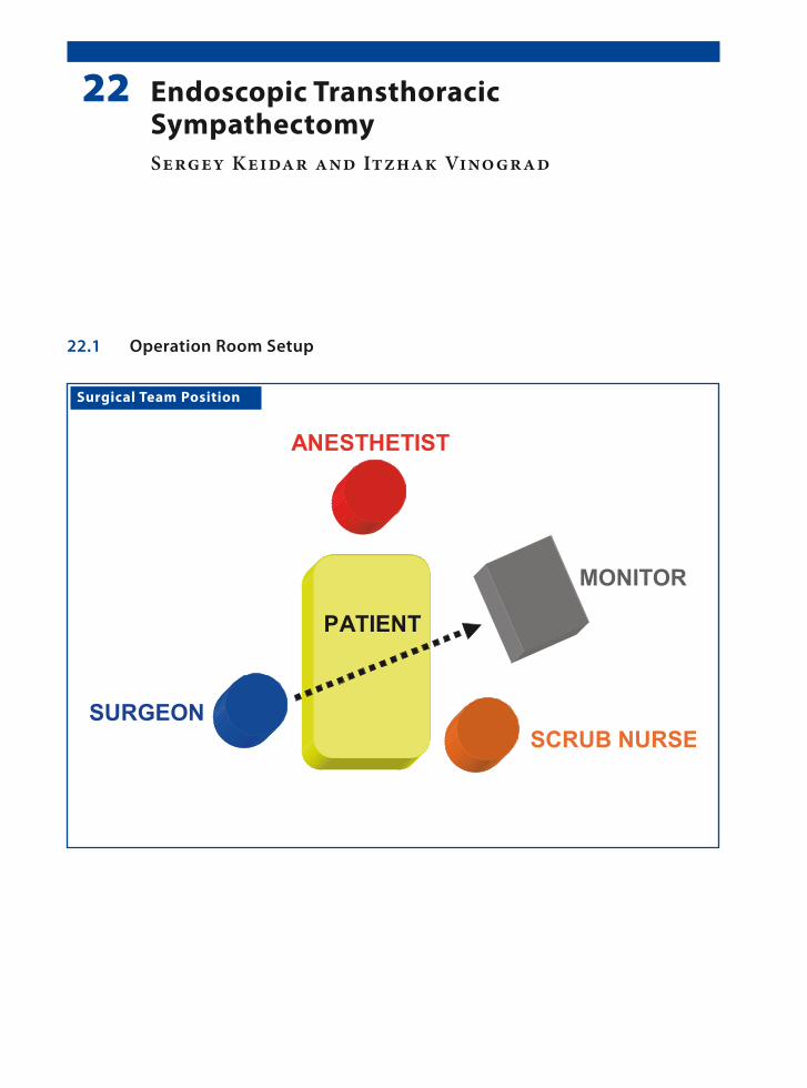
Surgical Team Position
22.1 Operation Room Setup
22 Endoscopic Transthoracic SympathectomySergey Keidar and Itzhak Vinograd

1�� Chapter 22 Endoscopic Transthoracic Sympathectomy
22.3 Special Instruments
• 10-mm, 0° operating scope with a 5-mm central working channel
• Monopolar hook cautery
Port Placement Sites
22.2 Patient Positioning
Semisitting position with hands abducted to a 90° angle providing exposure of both axillae. This set-up is for right-side sympathectomy. For the left side, a mirror image of the set-up is preferred.
22.4 Location of Access Points
Sergey Keidar and Itzhak Vinograd 1��
22.5 Indications
1. Palmar and axillary hyperhidrosis causing psy-chological, social, and occupational problems.
2. Failure of conservative treatment.3. Upper extremity pain syndromes.4. Early surgery will rescue children from exces-
sive physical discomfort.
22.6 Contraindications
Previous lung surgery, empyema.
22.7 Preoperative Considerations
1. Explain possible complications such as Horner‘s syndrome, intercostal neuralgia, and compen-satory sweating.
2. It is advisable to begin on the right to avoid ar-rhythmia, since the severance of the left stellate ganglion increases the threshold for arrhyth-mia.
3. Imaging with computed tomography or mag-netic resonance imaging of the cervical and tho-racic spine and brachial plexus may be indicated in selected cases when the normal anatomy is in doubt.
22.9 Procedure Variations
1. Biportal procedure (two 5-mm ports, one for optics and the other for instrument).
2. Laser or harmonic scalpel to cauterize the sym-pathetic ganglia.
3. Depending on the number of ports employed, a 0° or 30° endoscope option may be used for vi-sualization.
4. Either the double-lumen endotracheal tube or the 8- 10-mmHg insufflation pressure pneumo-thorax option may be chosen.
22.10 Technique of Endoscopic Transthoracic Sympathectomy
Please see Figs. 1–6.
22.8 Technical Notes
1. T2–T4 sympathectomy for axillary hyperhidro-sis.
2. T2–T3 sympathectomy for palmar hyperhidro-sis.
3. Avoid T1 stellate ganglion.4. Electrocautery ablation of the sympathetic seg-
ment; strictly coagulate above the rib surface.5. Upon completion on one side, sympathectomy
is then performed on the opposite side.6. Lung reinflation under visual control with posi-
tive pressure.
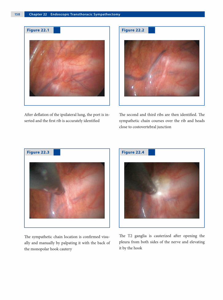
1�� Chapter 22 Endoscopic Transthoracic Sympathectomy
Figure 22.1 Figure 22.2
Figure 22.3 Figure 22.4
After deflation of the ipsilateral lung, the port is in-serted and the first rib is accurately identified
The second and third ribs are then identified. The sympathetic chain courses over the rib and heads close to costovertebral junction
The sympathetic chain location is confirmed visu-ally and manually by palpating it with the back of the monopolar hook cautery
The T2 ganglia is cauterized after opening the pleura from both sides of the nerve and elevating it by the hook

Sergey Keidar and Itzhak Vinograd 1��
Recommended Literature
1. Gossot D, Galetta D, Pascal A, Debrosse D, Caliandro R, Girard P, Stern JB, Grunenwald D (2003) Long-term results of endoscopic thoracic sympathectomy for upper limb hyperhidrosis. Ann Thorac Surg 75: 1075–1079
2. Lin TS, Fang HY (1999) Transthoracic endoscopic sympathectomy in the treatment of palmar hyperhi-drosis – with emphasis on perioperative management (1,360 case analyses) Surg Neurol 52:453–457
3. Lin TS, Kuo SJ, Chou MC (2002) Uniportal endoscopic thoracic sympathectomy for treatment of palmar and axillary hyperhidrosis: analysis of 2000 cases. Neuro-surgery 51:84–87
Figure 22.5 Figure 22.6
Extension of cauterization over the second and third rib provides complete denervation of T2 and T3, wich also includes the division of Kuntz nerve
The port is removed and expansion of the lung is vi-sualized through the endoscope. Skin is closed un-der the Valsalva maneuver

Surgical Team Position
MONITOR
SURGEON
1. ASSISTANT SCRUB NURSE
ANESTHETIST
2. ASSISTANTPATIENT
23.1 Operation Room Setup
23 Anterior Discectomy and HemivertebrectomyJerry Kieffer

1�2 Chapter 23 Anterior Discectomy and Hemivertebrectomy
23.3 Special Instruments
1. Orthopedic endoscopic instruments – rongeurs– forceps– elevators– curettes– osteotomes
2. Endoscopic fan retractor3. High-speed bur for bone resections4. Hemostatic agents
Port Placement Sites
23.2 Patient Positioning
Lateral decubitus position with the convexity side up, the upper arm resting on a raised arm board.
23.4 Location of Access Points

Jerry Kieffer 1�3
23.5 Indications
1. Deformity correction: anterior discectomy and fusion with or without instrumentation, hemi-vertebrectomy.
2. Trauma: anterior fusion with or without instru-mentation.
3. Infection: abscess evacuation and curettage.4. Tumor: biopsy.
23.6 Contraindications
Intolerance to single-lung ventilation.
23.7 Preoperative Considerations
1. Double-lumen intubation is mandatory for ipsi-lateral lung collapse in thoracoscopic proce-dures. If total lung collapse is not possible, use a fan retractor.
2. Somatosensory and motor-evoked potentials are monitored during the whole procedure.
3. Use a fluoroscopic C-arm to determine the disc levels and mark them directly onto the patient’s skin, as well as the entry points of the ports.
23.9 Procedure Variations
1. Anterior thoracic discectomy and fusion is completed by anterior endoscopic instrumenta-tion and correction in a single-staged procedure or by posterior instrumentation and correction in a single- or double-staged procedure.
2. Thoracoscopic hemivertebrectomy is completed by posterior instrumentation and correction in a single-staged procedure.
3. If the hemivertebra wears a surplus rib, its head and proximal part are also removed endoscopi-cally.
23.10 Thoracoscopic Anterior Discectomy and Fusion
Please see Figs. 1–12.
23.8 Technical Notes
1. In severe deformity with contact between the spine and the rib cage, a chest wall suspension is used to create working space.
2. Incisions for ports are made over the rib, allow-ing harvesting of a 2-cm rib segment to be used as an autologous bone graft.
3. Ligation of segmental vessels is not necessary in anterior discectomy.

1�� Chapter 23 Anterior Discectomy and Hemivertebrectomy
Figure 23.1 Figure 23.2
Figure 23.3 Figure 23.4
The pleura is lifted with a forceps and incised with electrocautery
The superior and inferior margins of the disc are in-cised with electrocautery
The discectomy goes down to the posterior mar-gin of the annulus using a graduated endoscopic rongeur. The disc space created (to the left of the rongeur in picture) is filled with hemostatic gauze
The growth plates are curetted

Jerry Kieffer 1��
Figure 23.5 Figure 23.6
The hemostatic gauzes are removed prior to graft-ing
The gap created by the discectomy is filled with bone chips

1�� Chapter 23 Anterior Discectomy and Hemivertebrectomy
Figure 23.9 Figure 23.10
Two needles are placed at the estimated superior and inferior margins of the hemivertebra and their position is checked with fluoroscopy
Growth-plate removal is completed with a standard rongeur
Figure 23.7 Figure 23.8
The pleura is incised with electrocautery over the hemivertebra and the superior and inferior adja-cent vertebra
The growth cartilages above and below the hemi-vertebra are curetted
23.11 Thoracoscopic Hemivertebrectomy

Jerry Kieffer 1��
Recommended Literature
1. Benazet JP (2000) Chirurgie Endoscopique du Rachis, Cahiers d’Enseignement de la SOFCOT (75). Elsevier, Paris, ISBN 978-2-84299-222-4
2. Lenke L, Betz R, Harms J (eds) (2004) Modern Ante-rior Scoliosis Surgery. Quality Medical Publishing, St. Louis, ISBN-10 1-57626-134-4
3. Regan JJ, Lieberman IH (2002) Atlas of Minimal Ac-cess Spine Surgery, 2nd edn. Quality Medical Publish-ing, St. Louis, ISBN-10 1-57626-100-X
Figure 23.11 Figure 23.12
The body of the hemivertebra is removed with a high-speed bur down to the posterior longitudinal ligament
As epidural bleeding is not uncommon, a hemo-static sheet is placed at the bottom of the gap cre-ated by the hemivertebrectomy
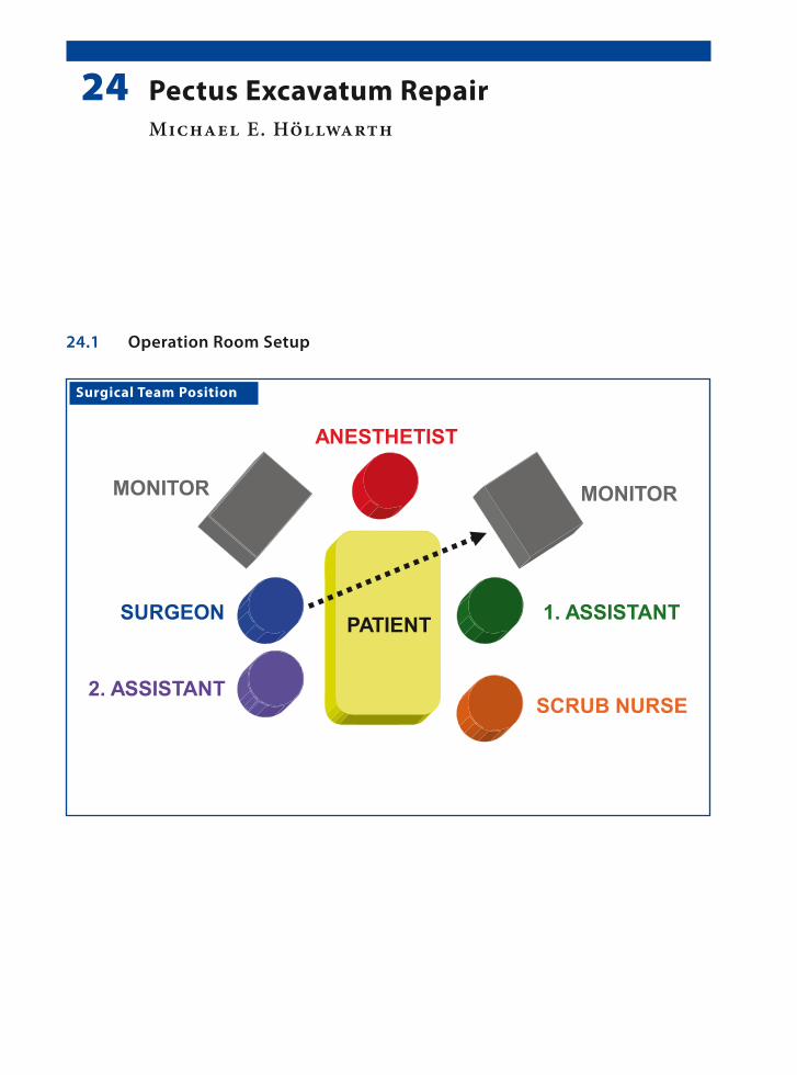
Surgical Team Position
24.1 Operation Room Setup
24 Pectus Excavatum RepairMichael E. Höllwarth
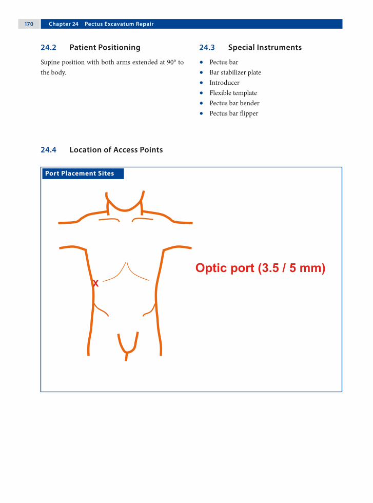
1�0 Chapter 2� Pectus Excavatum Repair
Port Placement Sites
24.3 Special Instruments
• Pectus bar• Bar stabilizer plate• Introducer• Flexible template• Pectus bar bender• Pectus bar flipper
24.2 Patient Positioning
Supine position with both arms extended at 90° to the body.
24.4 Location of Access Points
Michael E. Höllwarth 1�1
24.5 Indications
1. Improvement of chest-wall appearance.2. Pulmonary compromise with activity.3. Chest-wall pain.4. Psychosocial impairment.
24.6 Contraindications
1. There are no absolute contraindications for pec-tus excavatum
2. Combined pectus carinatum and excavatum de-formities.
24.7 Preoperative Considerations
1. Intravenous antibiotic cefuroxime (30 mg/kg; max 1.5 g) is administered at the time of anes-thesia induction.
2. Drapes are placed so as to provide complete ex-posure of the chest wall as well as the lateral tho-rax.
3. Evaluate chest films with regard to the level of the diaphragm, which is important to deter-mine the level of port insertion and avoid injury to the liver.
24.9 Procedure Variations
1. Substernal incision to elevate the sternum in older patients with a deep and rigid chest wall
2. Use of bilateral thoracoscopy.3. Use of bilateral stabilizer plates.4. Extrapleural placement of the pectus bar.
24.10 Minimal-Access Repair of Pectus Excavatum
Please see Figs. 1–12.
24.8 Technical Notes
1. Careful evaluation of the diaphragm on chest films to avoid trocar-related injuries to the dia-phragm or liver.
2. The pectus bar is placed under the lowest part of the sternal depression.
3. In the case of severe deformities a second pectus bar may be required
4. Postoperative evacuation of the insufflated gas through the port is important to minimize mor-bidity due to residual pneumothorax. For this, the patient is placed in a left semilateral, head-down position.
5. The bar must enter and exit the thoracic cavity close to the right and left ridge of the depres-sion.

1�2 Chapter 2� Pectus Excavatum Repair
Figure 24.1 Figure 24.2
Figure 24.3 Figure 24.4
The thoracic contours are marked with a flexible template and the pectus bar is bent to the desired shape
Bilateral horizontal thoracic skin incisions are placed at the predetermined point of pectus bar in-sertion and exit. The muscles are incised along their fibers and a space is created between the ribs and the muscle layers towards the edge of the pectus
A 30° scope is introduced into the optic port placed in the anterior axillary line in the right lower rib margin and above the level of the diaphragm
The introducer is inserted through the right inci-sion into the thoracic cavity

Michael E. Höllwarth 1�3
Figure 24.5 Figure 24.6
Figure 24.7 Figure 24.8
The introducer tip is passed through the intercos-tal muscles medial to the rim of the pectus and in-serted into the right thoracic cavity
The introducer tip is slowly advanced through the retrosternal and prepericardial plane under visual control, and exits again medial to the pectus rim
Two umbilical tapes are knotted to the introducer tip on the contralateral side and retrieved
The pectus bar is then knotted to the tape and intro-duced into the right thorax

1�� Chapter 2� Pectus Excavatum Repair
Figure 24.9 Figure 24.10
Figure 24.11 Figure 24.12
Using the umbilical tape as a guide, the pectus bar is advanced to the contralateral side and flipped
A single stabilizer plate is used on the right side and slid over the free end of the pectus bar
Using a Deschamp’s needle, a polydiaxanone cord is placed around the stabilizer plate, the bar and the underlying rib
The polydioxanone cord is tied to secure the pectus bar and stabilizer plate to the underlying rib

Michael E. Höllwarth 1��
Recommended Literature
1. Nuss D, Croitoru DP, Kelly RE Jr, Goretsky MJ, Nuss KJ, Gustin TS (2002) Review and discussion of the com-plications of minimally invasive pectus excavatum re-pair. Eur J Pediatr Surg 12:230–234
2. Saxena AK, Castellani C, Hollwarth ME (2007) Surgical aspects of thoracoscopy and efficacy of right thoraco- scopy in minimally invasive repair of pectus excava-tum. J Thorac Cardiovasc Surg 133:1201–1205
3. Schalamon J, Pokall S, Windhaber J, Hoellwarth ME (2006) Minimally invasive correction of pectus ex-cavatum in adult patients. J Thorac Cardiovasc Surg 132:524–529

Section 3 Gastrointestinal Procedures

Surgical Team Position
25.1 Operation Room Setup
25 Diagnostic LaparoscopyAtsuyuki Yamataka and Tadaharu Okazaki

1�0 Chapter 2� Diagnostic Laparoscopy
Port Placement Sites
25.3 Special Instruments
• Endoscopic retractors• Babcock forceps• Specimen retrieval bag• Ultracision® shears (Johnson & Johnson Med-
ical Products, Ethicon Endo-Surgery, Cincin-nati, OH, USA)
• Cholangiogram needles
25.2 Patient Positioning
Supine and secured to allow tilting of the operat-ing table intraoperatively to facilitate examination of the peritoneal cavity.
25.4 Location of Access Points

Atsuyuki Yamataka and Tadaharu Okazaki 1�1
25.5 Indications
1. Acute abdominal pain including intestinal ob-struction.
2. Recurrent or chronic abdominal pain.3. Meckel’s diverticulum diagnosis.4. Antenatally diagnosed intestinal atresia.5. Evaluation of abdominal masses – including
malignant tumor, appendiceal mass, duplica-tion cyst, and mesenteric cyst.
6. Hirschsprung’s disease – colon biopsies.7. Evaluation of impalpable testes and intersex
states.8. Investigation of pelvic mass.9. Blunt and penetrating visceral trauma.
25.6 Contraindications
1. Uncorrected hypotension, hypoxia, and bleed-ing disorders.
2. Severe bowel obstruction with dilated bowel loops.
25.7 Preoperative Considerations
1. Patients should be prepared for general anesthe-sia. Blood grouping and crossmatching should be undertaken if clinically indicated.
2. General anesthesia with optimal muscle relax-ation.
3. Place a nasogastric tube and urinary catheter.4. Indications for preoperative antibiotics are the
same as for the open procedure.5. Liaison with histopathology services if biopsies
are planned.
25.8 Procedure Variations
1. The viscera should be examined using a consis-tent routine starting with a clockwise inspection from the cecum and appendix, right colon, gall-bladder, liver, stomach, spleen, left colon, pelvic organs, internal inguinal rings, gonadal vessels, and back to the ileocecal region.
2. The entire small bowel can be inspected using two pairs of atraumatic grasping forceps until the duodenojejunal junction is reached.
3. Two linked monitors are ideal to avoid difficul-ties with parallax.

1�2 Chapter 2� Diagnostic Laparoscopy
25.9 Appendiceal Mass
Please see Figs. 1 and 2.
Figure 25.1 Figure 25.2
An appendiceal mass is carefully opened and the purulent exudate is aspirated completely using a suction/irrigation device
A J-VAC (Ethicon, Somerville, NJ, USA) drain-age tube is placed within the abscess cavity. Lapa-roscopic appendectomy is planned several months later

Atsuyuki Yamataka and Tadaharu Okazaki 1�3
25.10 Stoma Closure
Please see Figs. 3 and 4.
Figure 25.3 Figure 25.4
The bowel loop of the stoma is clearly visualized under laparoscopic control
A stoma can be removed under laparoscopic con-trol (arrowheads). This is less traumatic to the ab-dominal wall and prevents bowel injury

1�� Chapter 2� Diagnostic Laparoscopy
25.11 Laparoscopic-Assisted Cholangiography
Please see Figs. 5–8.
Figure 25.5 Figure 25.6
In patients with biliary atresia, the gallbladder is usually atretic and direct insertion of a catheter is technically difficult
If the gallbladder is of reasonable size, the fundus can be exteriorized through a small right subcostal incision following partial laparoscopic dissection from the liver bed

Atsuyuki Yamataka and Tadaharu Okazaki 1��
Figure 25.7 Figure 25.8
The gallbladder fundus, exteriorized through the ab-dominal wall, is held by a pair of mosquito clamps
A 5-Fr feeding tube is inserted into the gallbladder for cholangiography

1�� Chapter 2� Diagnostic Laparoscopy
25.12 Antenatally Diagnosed Small-Bowel Atresia
Please see Figs. 9 and 10.
Figure 25.9
Recommended Literature
1. Okazaki T, Miyano G, Yamataka A, Kobayashi H, Koga H, Lane GJ, Miyano T (2006) Diagnostic laparoscopy-assisted cholangiography in infants with prolonged jaundice. Pediatr Surg Int 22:140–143
2. Marusasa T, Miyano G, Kato Y, Yanai T, Okazaki T, Ichikawa S, Lane GJ, Yamataka A (2007) New primary management for appendiceal masses in children: lap-aroscopic drainage. J Laparoendosc Adv Surg Tech 17:497–500
3. Yamataka A, Koga H, Shimotakahara A, Urao M, Yanai M, Kobayashi H, Lane G, Miyano T (2004) Laparoscopy-assisted surgery for prenatally diagnosed small bowel atresia: simple, safe, and virtually scar free. J Pediatr Surg 39:1815–1818
Figure 25.10
A 0° laparoscope is introduced through the umbil-ical port and both the proximal (P) and distal (D) bowel ends are identified
Both the proximal and distal bowel ends are exte-riorized via the umbilical port wound, which is ex-panded by using a wound retractor, and anastomo-sis is performed
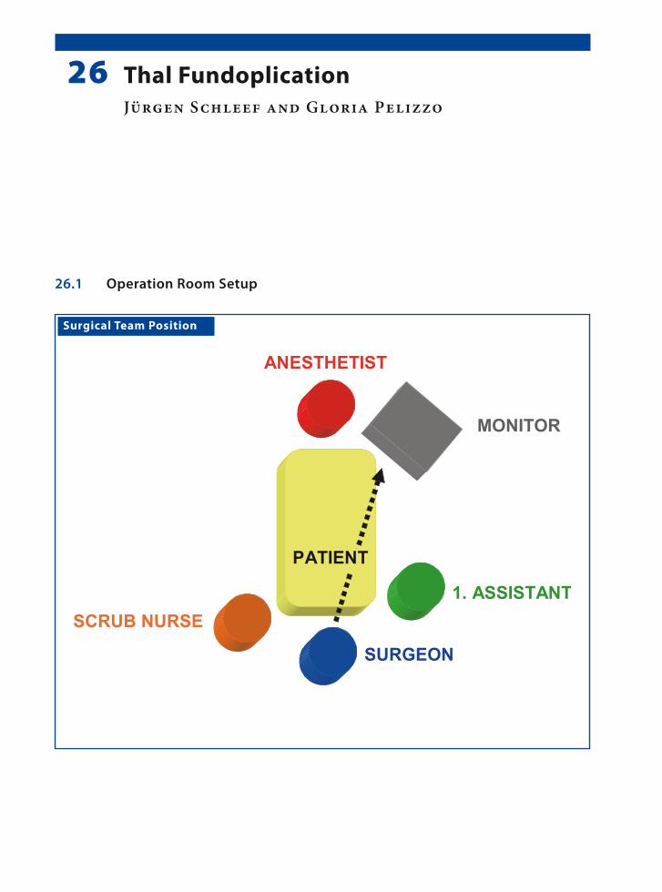
Surgical Team Position
26.1 Operation Room Setup
26 Thal FundoplicationJürgen Schleef and Gloria Pelizzo

1�� Chapter 2� Thal Fundoplication
Port Placement Sites
26.3 Special Instruments
Esophageal retractor.
26.2 Patient Positioning
Supine with both arms tucked to the sides. Frog-leg position in small children, while in adolescents the legs are opened to allow the surgeon to stand in be-tween.
26.4 Location of Access Points

Jürgen Schleef and Gloria Pelizzo 1��
26.5 Indications
Gastroesophageal reflux:1. Refractory to medical treatment.2. With aspiration pneumonia.3. Failure to thrive.
26.6 Contraindications
1. Severe respiratory distress associated with any of the aforementioned indications.
2. Severe scoliosis (relative contraindication).3. Prior abdominal surgery with adhesions (rela-
tive contraindication).
26.7 Preoperative Considerations
1. The bladder has to be emptied before the proce-dure with the Crede maneuver or the placement of a Foley catheter.
2. Neurological patients should be positioned ac-cording to the severity of scoliosis. Sufficient support should be provided to the body of to stabilize it during the procedure.
3. The size of nasogastric tube or bougie should be decided upon before the procedure commences; and sufficient access of the head area should be provided to the anesthetist.
26.9 Procedure Variations
1. Umbilical tapes can be used to retract the eso-phagus instead of the esophageal retractor.
2. Short gastric vessels may have to be mobilized to facilitate mobilization of the fundus.
3. In patients with a percutaneous endoscopic gas-trostomy, it is not necessary to take down the stoma for fundoplication.
4. LigaSure™ (Valleylab, Boulder, CO, USA) or Ul-tracision® (Johnson & Johnson Medical Prod-ucts, Ethicon Endo-Surgery, Cincinnati, OH, USA) shears may be used in older children.
26.10 Laparoscopic Thal Fundoplication
Please see Figs. 1–6.
26.8 Technical Notes
1. The liver can be retracted using a three-finger liver retractor. Otherwise, a simple grasper can be introduced from the right side to grasp the diaphragm, thereby raising the liver.
2. Suturing of the fundus to the esophagus is done with the first line of sutures. This is followed by a second suture line, which sutures the fundus to the diaphragm and the right crus.
3. Port placements have to be adjusted in children with severe scoliosis.

1�0 Chapter 2� Thal Fundoplication
Figure 26.1 Figure 26.2
Figure 26.3 Figure 26.4
The avascular window of the gastrohepatic liga-ment is opened with monopolar hook cautery and the peritoneum around the hiatus is dissected. The esophagus is held retracted during the dissection
A bougie is placed in the esophagus. The left and the right crus of the diaphragm are sufficiently ex-posed and nonabsorbable sutures are used to close the esophageal hiatus
Stay sutures are used on either side of the esoph-agus to secure it to the diaphragm. The fundus is mobilized anteriorly and is sutured on the right side of the esophagus
The first row of sutures is used to suture the fundus to the esophagus. Sutures are places on the anterior side of the esophagus and along the right edge of the esophagus

Jürgen Schleef and Gloria Pelizzo 1�1
Recommended Literature
1. Garzi A, Valla JS, Molinaro F, Amato G, Messina M (2007) Minimally invasive surgery for achalasia: com-bined experience of two European centers. J Pediatr Gastroenterol Nutr 44:587–591
2. Martinez-Frontanilla LA, Sartorelli KH, Hasse GM, Meagher DP Jr (1996) Laparoscopic Thal fundopli-cation with gastrostomy in children. J Pediatr Surg. 31:275–276
3. Van der Zee DC, Bax KN, Ure BM, Besselink MG, Pak-vis DF (2002) Long-term results after laparoscopic Thal procedure in children. Semin Laparosc Surg 9:168–171
Figure 26.5 Figure 26.6
A second row of sutures is placed along the line of the first row to further secure the fundus to the di-aphragm and the right crus of the diaphragm. The second row reinforces the first row of sutures
The final view of the anterior wrap before closure of the abdomen. The bougie is removed by the anes-thetist under visual aid

Surgical Team Position
27.1 Operation Room Setup
27 Nissen FundoplicationShawn D. St Peter and George W. Holcomb III

1�� Chapter 2� Nissen Fundoplication
Port Placement Sites
XXX
Optic port (3.5 / 5 mm)*
Work port (2 / 3.5 mm)*
Work port (2 / 5 mm)*
*Port size depends onthe age of the patient
XX
27.3 Special Instruments
• Endoscopic liver rectractor• Patients over 5 years age require one of the fol-
lowing devices to divide short gastric vessels: – Ultracision® shears (Johnson & Johnson Med-
ical Products, Ethicon Endo-Surgery, Cincin-nati, OH, USA) or
– LigaSure™ (Valleylab, Boulder, CO, USA) or – EnSeal® (SurgRx, Redwood City, CA, USA)
27.2 Patient Positioning
Frog-leg position at the end of the table with arms tucked for infants and small children. Older chil-dren require stirrups.
27.4 Location of Access Points

Shawn D. St Peter and George W. Holcomb III 1��
27.5 Indications
Gastroesophageal reflux causing one or more of the following problems:1. Failure to thrive.2. Aspiration pneumonia.3. Apparent life-threatening event.4. Esophagitis, persistent vomiting or severe symp-
toms refractory to medical therapy.
27.6 Contraindications
Severe cardiac or pulmonary diseases and severe musculoskeletal malformations.
27.8 Technical Notes
1. If a gastrostomy button is to be placed, identify the spot on the abdomen prior to insufflation and this will serve as the port used by the sur-geon’s operating right hand.
2. Place a 2-0 nonabsorbable suture in the crus posteriorly, tie a knot, then secure it to the pos-terior esophagus.
3. Place four interrupted 3-0 nonabsorbable su-tures between the crus and the esophagus cir-cumferentially (7, 11, 2, and 5 o’clock).
4. Identify the portion of fundus to be brought around the esophagus, then push it back through to the left side while the bougie is inserted.
27.7 Preoperative Considerations
1. Place a nasogastric tube and have bougie avail-able for the anesthesiologist to place.
2. Place foot pedals for hemostatic devices at the end of the bed.
3. Choose the length of sutures to be prepared by the scrub nurse.
4. Prep to the nipples as the skin will be drawn in-feriorly by insufflation.
5. Drape in a manner that will provide easy access to the mouth for the anesthesiologist.
6. Place the drape in reverse direction. So the head portion, which is shorter, is not in the way of the surgeon’s feet.
27.9 Procedure Variations
1. A 5-mm port for the surgeon’s right hand allows vessel sealing devices to be used.
2. The esophagophrenic attachments can be com-pletely mobilized or left in place laterally and anteriorly.
3. Pledgets may be employed to buttress the fun-doplasty sutures.
4. A liver retractor can be a locking grasping forcep secured onto the right crus of the diaphragm
5. A table-mounted device can be used to hold the liver retractor in place.
27.10 Laparoscopic Nissen Fundoplication
Please see Figs. 1–6.
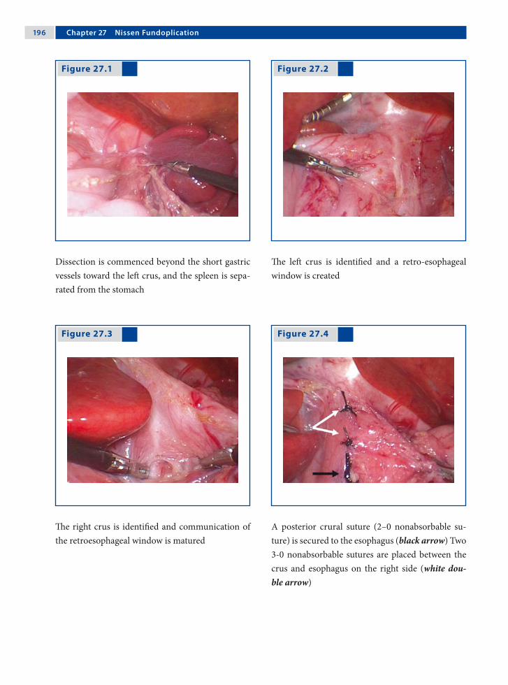
1�� Chapter 2� Nissen Fundoplication
Figure 27.1 Figure 27.2
Figure 27.3 Figure 27.4
Dissection is commenced beyond the short gastric vessels toward the left crus, and the spleen is sepa-rated from the stomach
The left crus is identified and a retro-esophageal window is created
The right crus is identified and communication of the retroesophageal window is matured
A posterior crural suture (2–0 nonabsorbable su-ture) is secured to the esophagus (black arrow) Two 3-0 nonabsorbable sutures are placed between the crus and esophagus on the right side (white dou-ble arrow)

Shawn D. St Peter and George W. Holcomb III 1��
Recommended Literature
1. St Peter SD, Holcomb GW III (2008) Gastroesophageal reflux disease and fundoplication in infants and chil-dren. Ann Pediatr Surg (in press)
2. St Peter SD, Valusek TA, Calkins CM, Shew SB, Ost-lie DJ, Holcomb GW III (2007) Use of esophagocru-ral sutures and minimal esophageal dissection reduces the incidence of postoperative transmigration of lap-aroscopic Nissen fundoplication wrap. J Pediatr Surg 42:25–29
3. St Peter SD, Valusek TA, Ostlie DJ, Holcomb GW III (2007) The use of biosynthetic mesh to enhance hiatal repair at the time of redo Nissen fundoplication. J Ped Surg 42:1298–1301
Figure 27.5 Figure 27.6
As on the right, two 3-0 nonabsorbable esophago-crural sutures are placed on the left side
Nissen fundoplication is formed with three inter-rupted 2–0 nonabsorbable sutures, the superior of which incorporates the anterior esophagus

Surgical Team Position
28.1 Operation Room Setup
28 Toupet FundoplicationPhilippe Montupet and Amulya K. Saxena

200 Chapter 2� Toupet Fundoplication
Port Placement Sites
28.3 Special Instruments
• Endoscopic liver retractor (three fingers) or snake retractor
• Monopolar hook or scissors• LigaSure™ (Valleylab, Boulder, CO, USA) or • Ultracision® harmonic scalpel (Johnson & John-
son Medical Products, Ethicon Endo-Surgery, Cincinnati, OH, USA).
28.2 Patient Positioning
Reverse Trendelenburg with folded legs wrapped and fixed at the table.
28.4 Location of Access Points

Philippe Montupet and Amulya K. Saxena 201
28.5 Indications
1. Severe gastroesophageal reflux.2. Esophageal dysmotility.3. Esophageal peptic stricture.4. Heller procedure’s complement.
28.6 Contraindications
Severe cachexia (delay surgery).
28.8 Technical Notes
1. The posterior vagus nerve is a valuable land-mark during hiatal dissection.
2. The esophagus is pulled down to expose a wide retrocardial window.
3. Two stitches should be used to tack the poster-ior wrap to the right pillar after the fundus has been widely drawn.
4. Use two rows of stitches along the sides of the esophagus after encircling the fundus on three-quarters of its girth.
28.7 Preoperative Considerations
1. Discuss outcomes with parents regarding tran-sient dysphagia, controls, and preserved ability to belch.
2. Upper gastrointestinal studies to evaluate gas-tric emptying.
3. Avoid nitrous oxide anesthesia to prevent bowel dilatation.
4. Intracorporeal knotting is recommended for su-turing of the wrap.
28.9 Procedure Variations
1. A temporary frame-stitch can tack the both sides of the fundus encircling the esophagus.
2. The number of stitches on each row has to be increased in case of neurologically impaired pa-tients.
3. In a redo procedure, care should be taken to separate the liver from the wrap. This can be challenging.
4. Intracorporeal knotting ensures a suitable tight-ness. A final picture is a useful routine.
28.10 Laparoscopic Toupet Fundoplication with Three-Port Technique
Please see Figs. 1–6.

202 Chapter 2� Toupet Fundoplication
Figure 28.1 Figure 28.2
Figure 28.3 Figure 28.4
Three ports are placed in the upper abdomen The posterior vagus nerve is identified as a land-mark and a large retrocardial window is created
The intracorporeal knotting technique is favorable during this procedure
The fundus wrap has to be drawn bulging in front of the pillar and three sutures tack both together
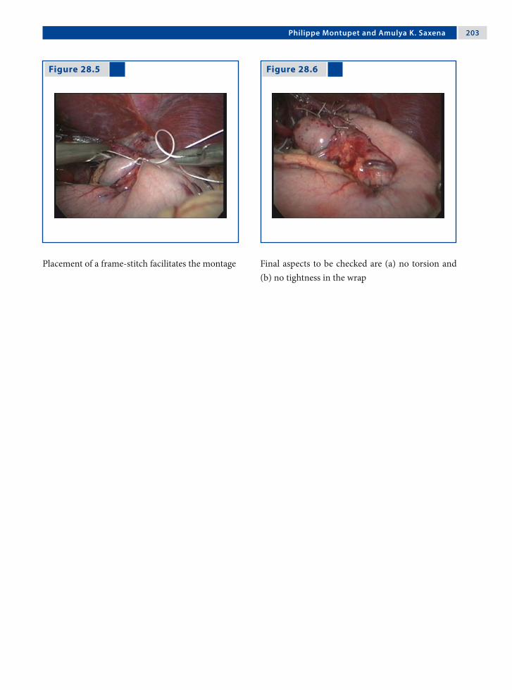
Philippe Montupet and Amulya K. Saxena 203
Figure 28.5 Figure 28.6
Placement of a frame-stitch facilitates the montage Final aspects to be checked are (a) no torsion and (b) no tightness in the wrap

20� Chapter 2� Toupet Fundoplication
28.11 Laparoscopic Toupet Fundoplication with Four-Port Technique
28.11.1 Port Placement Sites
Please see Figs. 7–14.
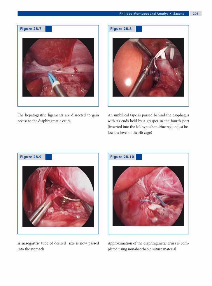
Philippe Montupet and Amulya K. Saxena 20�
Figure 28.7 Figure 28.8
Figure 28.9 Figure 28.10
The hepatogastric ligaments are dissected to gain access to the diaphragmatic crura
An umbilical tape is passed behind the esophagus with its ends held by a grasper in the fourth port (inserted into the left hypochondriac region just be-low the level of the rib cage)
A nasogastric tube of desired size is now passed into the stomach
Approximation of the diaphragmatic crura is com-pleted using nonabsorbable suture material

20� Chapter 2� Toupet Fundoplication
Figure 28.11 Figure 28.12
Figure 28.13 Figure 28.14
Sutures are placed on the left and right side of the esophagus to secure it to the diaphragm
The fundus is then passed behind the esophagus and positioned for the wrap
The left side is sutured initially with a line of three sutures, which are tied intracorporeally. The upper-most suture of the wrap is also secured to the dia-phragm
The 270° wrap is completed with left-side suturing, and is checked for torsion and tightness

Philippe Montupet and Amulya K. Saxena 20�
Recommended Literature
1. Bensoussan AL, Yazbeck S, Carceller-Blanchard A (1994) Results and complications of Toupet’s partial posterior wrap: 10 years experience. J Pediatr Surg 29:1215–1217
2. Esposito C, Montupet P, Amici G (2000) Complica-tions of laparoscopic antireflux surgery in childhood. Surg Endosc 14:658–660
3. Montupet P (2002) Laparoscopic Toupet’s fundoplica-tion in children. Semin Laparosc Surg 9:163–167

Surgical Team Position
29.1 Operation Room Setup
29 Cardiomyotomy for Esophageal AchalasiaLuigi Bonavina

210 Chapter 2� Cardiomyotomy for Esophageal Achalasia
Port Placement Sites
29.3 Special Instruments
Ultracision® harmonic scalpel. (Johnson & Johnson Medical Products, Ethicon Endo-Surgery, Cincin-nati, OH, USA)
29.2 Patient Positioning
Patient is in 20–30° reverse Trendelenburg lithot-omy position with arms tucked to the side.
29.4 Location of Access Points

Luigi Bonavina 211
29.5 Indications
During the past two decades, laparoscopic cardio-myotomy combined with an anterior (Dor) fundo-plication has emerged as the initial approach of choice in the treatment of esophageal achalasia. The operation is indicated to provide symptomatic relief of dysphagia and food regurgitation, and to prevent aspiration pneumonia and weight loss.
29.6 Contraindications
Extensive adhesions after previous abdominal sur-gery (relative contraindication).
29.8 Technical Notes
1. Avoid extensive dissection of the esophagogas-tric junction to prevent postoperative gastro-esophageal reflux.
2. Bleeding from the muscle edges of the myotomy is self-limiting; excessive electrocoagulation must be avoided.
3. Pay attention to the geometry of the Dor fundo-plication to avoid undue tension and to provide a uniform patch over the esophageal mucosa; in most patients there is no need to divide the short gastric vessels.
29.7 Preoperative Considerations
1. Insert a double-lumen nasogastric tube before surgery to wash and clean the esophageal lumen from food debris.
2. Give short-term antibiotic prophylaxis.
29.9 Procedure Variations
1. The esophagus should be encircled only in se-lected patients with sigmoid-type redundancy, associated hiatal hernia, or previous failed myo-tomy; in such circumstances the crura should be approximated posteriorly with interrupted stitches.
2. Intraoperative endoscopy may help to identify the cardia during the learning curve of this op-eration and during redo surgery. An endoscop-ically placed Rigiflex balloon dilator (Meditech-Boston Scientific, Natick, MA, USA) can be used to distend the cardia and facilitate the di-vision of residual muscle fibers. Air insufflation through the endoscope provides testing for oc-cult mucosal perforations.
29.10 Laparoscopic Cardiomyotomy for Esophageal Achalasia
Please see Figs. 1–6.

212 Chapter 2� Cardiomyotomy for Esophageal Achalasia
Figure 29.1 Figure 29.2
Figure 29.3 Figure 29.4
The anterior surface of the esophagus is exposed The Heller myotomy is started on the distal esoph-agus, on the left of the anterior vagus nerve, us-ing an L-shaped electrocoagulating hook, until the submucosal plane is identified
The myotomy is extended proximally for about 6 cm using the ultrasonic scissors with the active blade positioned upward
The myotomy is extended on the gastric side for about 2 cm to divide the oblique muscle fibers

Luigi Bonavina 213
Recommended Literature
1. Bonavina L (2006) Minimally invasive surgery for eso-phageal achalasia. World J Gastroenterol 12:5921–5925
2. Patti MG, Albanese CT, Holcomb GW III, Molena D, Fisichella PM, Perretta PM, Way LW (2001) Lapar-oscopic Heller myotomy and Dor fundoplication for esophageal achalasia in children. J Pediatr Surg 36:1248–1251
3. Rakita S, Villadolid D, Kalipersad C, Thometz D, Rose-murgy A (2007) Outcomes promote reoperative Heller myotomy for symptoms of achalasia. Surg Endosc 21:1709–1714
Figure 29.5 Figure 29.6
The first step of the Dor fundoplication is to se-cure the medial wall of the fundus (with three in-terrupted sutures) to the adjacent left muscle edge of the myotomy site (the first stitch includes the left diaphragmatic crus)
A more lateral portion of the anterior fundus wall is secured with three interrupted sutures to the right muscle edge of the myotomy site (the first stitch in-cludes the right diaphragmatic crus)

Surgical Team Position
30.1 Operation Room Setup
30 Gastric BandingAmulya K. Saxena

21� Chapter 30 Gastric Banding
30.3 Special Instruments
• Swedish adjustable gastric band (SAGB) (Ob-tech, Ethicon Endo-Surgery, Cincinnati, OH, USA)
• LigaSure™ (Valleylab, Boulder, CO, USA)• Goldfinger® dissector (Johnson & Johnson Med-
ical Products, Ethicon Endo-Surgery, Cincin-nati, OH, USA)
Port Placement Sites
30.2 Patient Positioning
Modified lithotomy position. The surgeon stands between the spread legs of the patient.
30.4 Location of Access Points

Amulya K. Saxena 21�
30.5 Indications
1. Body mass index above 40.2. Age between 12 and 55 years.3. Failure of dietary or weight-loss drug therapy
for more than 1 year.4. Willingness to comply with the substantial life-
long dietary restrictions required.5. Acceptable operative risk.
30.6 Contraindications
1. Untreated glandular diseases.2. Inflammatory gastrointestinal tract diseases.3. Severe cardiopulmonary disease.4. Dependency on alcohol or drugs.5. Mental retardation or emotional instability.6. Serious concerns about the compliance of the
patient
30.8 Technical Notes
1. Intra-abdominal access can be achieved by either an open technique using the Hasson can-nula, or a closed technique using the Veress needle.
2. One 15-mm trocar also is placed for introduc-tion of the laparoscopic adjustable gastric band into the peritoneal cavity.
3. The tubing is removed from the abdominal cav-ity through the subxiphoidal incision and con-nected to the reservoir placed and secured on the lowest part of the sternum.
30.7 Preoperative Considerations
1. The large body size and associated serious co-morbidities make patients who are morbidly obese high-risk surgical candidates.
2. Additional padded safety belts, gel or foam pads, and large elastic bandages are needed to prevent injury and movement of the extremities during surgery.
3. Gastric pH blockers are administered because of the increased incidence of gastroesophageal reflux disease and hiatal hernia in this patient population.
30.9 Procedure Variations
1. Perigastric technique: dissection begins at the lesser curve behind the stomach and proceeds toward the angle of His.
2. Pars flaccida technique: dissection starts dir-ectly in the avascular space of the pars flaccida toward the right crus and finally the left crus muscles.
3. Two-step technique: this begins with the pars flaccida technique, followed by a second dissec-tion near the stomach until the perigastric dis-section intercepts the pars flaccida dissection.
30.10 Laparoscopic “Swedish Adjustable Gastric Band” Procedure
Please see Figs. 1–6.
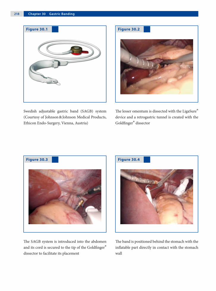
21� Chapter 30 Gastric Banding
Figure 30.1 Figure 30.2
Figure 30.3 Figure 30.4
Swedish adjustable gastric band (SAGB) system (Courtesy of Johnson & Johnson Medical Products, Ethicon Endo-Surgery, Vienna, Austria)
The lesser omentum is dissected with the LigaSure® device and a retrogastric tunnel is created with the Goldfinger® dissector
The SAGB system is introduced into the abdomen and its cord is secured to the tip of the Goldfinger® dissector to facilitate its placement
The band is positioned behind the stomach with the inflatable part directly in contact with the stomach wall

Amulya K. Saxena 21�
Recommended Literature
1. Ponce J, Fromm R, Paynter S (2006) Outcomes after laparoscopic adjustable gastric band repo-sitioning for slippage or pouch dilation. Surg Obes Relat Dis 2:627–31
2. Mizrahi S, Avinoah E (2007) Technical tips for laparoscopic gastric banding: years’ experience in 2800 procedures by a single surgical team. Am J Surg 193:160–5
3. Yitzhak A, Mizrahi S, Avinoah E (2006) Lapa-roscopic gastric banding in adolescents. Obes Surg 16:1318–22
Figure 30.5 Figure 30.6
The band is locked into place at the chosen location on the stomach (almost at the level of the cardia), creating a 20-ml gastric pouch
The stomach is sutured over the band with nonab-sorbable sutures. The tubing is brought out through the subxiphoidal incision where it is connected to the reservoir, which is placed on the distal sternum and secured to the fascia with sutures

Surgical Team Position
31.1 Operation Room Setup
31 PyloromyotomyCeleste M. Hollands and Sani Yamout

222 Chapter 31 Pyloromyotomy
Port Placement Sites
31.3 Special Instruments
• Lefthand – 3-mm single action atraumatic bowel grasper
• Right hand – arthroscopy knife• Tan pyloric spreader (Karl Storz, Tuttlingen,
Germany) • 5-mm Step trocar (VersaStep™; Auto Suture,
Norwalk, CT, USA) as optic port• 4-mm 30° scope
31.2 Patient Positioning
Infant placed horizontally across operating table in the supine position with arms by his/her side
31.4 Location of Access Points
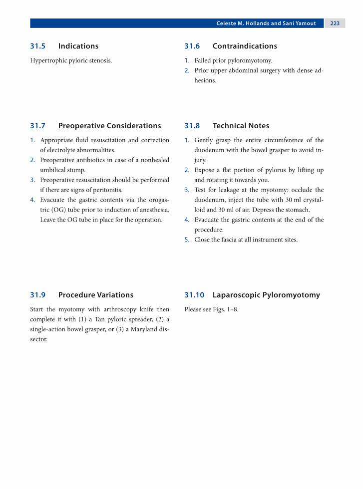
Celeste M. Hollands and Sani Yamout 223
31.5 Indications
Hypertrophic pyloric stenosis.
31.6 Contraindications
1. Failed prior pyloromyotomy.2. Prior upper abdominal surgery with dense ad-
hesions.
31.8 Technical Notes
1. Gently grasp the entire circumference of the duodenum with the bowel grasper to avoid in-jury.
2. Expose a flat portion of pylorus by lifting up and rotating it towards you.
3. Test for leakage at the myotomy: occlude the duodenum, inject the tube with 30 ml crystal-loid and 30 ml of air. Depress the stomach.
4. Evacuate the gastric contents at the end of the procedure.
5. Close the fascia at all instrument sites.
31.7 Preoperative Considerations
1. Appropriate fluid resuscitation and correction of electrolyte abnormalities.
2. Preoperative antibiotics in case of a nonhealed umbilical stump.
3. Preoperative resuscitation should be performed if there are signs of peritonitis.
4. Evacuate the gastric contents via the orogas-tric (OG) tube prior to induction of anesthesia. Leave the OG tube in place for the operation.
31.9 Procedure Variations
Start the myotomy with arthroscopy knife then complete it with (1) a Tan pyloric spreader, (2) a single-action bowel grasper, or (3) a Maryland dis-sector.
31.10 Laparoscopic Pyloromyotomy
Please see Figs. 1–8.

22� Chapter 31 Pyloromyotomy
Figure 31.1 Figure 31.2
The right- and left-hand working instruments are inserted directly through the abdominal wall after making a stab incision with a no. 11 blade inserted just to the widest portion of the blade
Working instruments shown inserted directly through the abdominal wall in the right and left up-per abdominal quadrants. The 5-mm Step trocar is inserted through the umbilicus
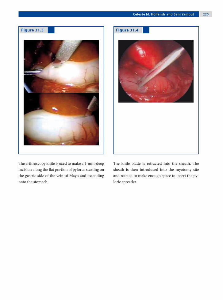
Celeste M. Hollands and Sani Yamout 22�
Figure 31.3 Figure 31.4
The arthroscopy knife is used to make a 1-mm-deep incision along the flat portion of pylorus starting on the gastric side of the vein of Mayo and extending onto the stomach
The knife blade is retracted into the sheath. The sheath is then introduced into the myotomy site and rotated to make enough space to insert the py-loric spreader

22� Chapter 31 Pyloromyotomy
Figure 31.5 Figure 31.6
Figure 31.7 Figure 31.8
The pyloric spreader is inserted until it touches the mucosa (this will avoid bleeding complication) and opened with a slow and steady motion to spread the myotomy
Note the circular muscle is visible on the gastric side of the myotomy, as is the transition from the thick-ened to normal muscle. Also note the asymmetry of a complete myotomy, which is most pronounced on the superior gastric border (arrow)
The “shoeshine” maneuver confirms that both sides of the myotomy move independently, confirming a complete myotomy Again, note the asymmetry on the gastric side
The omentum is placed over the myotomy after confirming there is no leak

Celeste M. Hollands and Sani Yamout 22�
Recommended Literature
1. Adibe OO, Nichol PF, Flake AW, Mattei P (2006) Com-parison of outcomes after laparoscopic and open pylo-romyotomy at a high-volume pediatric teaching hospi-tal. J Pediatr Surg 41:1676–1678
2. Greason KL, Thompson WR, Downey EC, La Sasso B (1995) Laparoscopic pyloromyotomy for infantile hy-pertrophic pyloric stenosis: a report of 11 cases. J Pedi-atr Surg 30:1571–1574
3. St Peter SD, Holcomb GW III, Calkins CM, Murphy JP, Andrews WS, Sharp RJ, Snyder CL, Ostlie DJ (2006) Open versus laparoscopic pyloromyotomy for pyloric stenosis: a prospective, randomized trial. Ann Surg 244:363–3670

Surgical Team Position
32.1 Operation Room Setup
32 Laparoscopic-Assisted JejunostomyCiro Esposito and Chiara Grimaldi

230 Chapter 32 Laparoscopic-Assisted Jejunostomy
Port Placement Sites
32.3 Special Instruments
Feeding tube for jejunal placement.
32.2 Patient Positioning
Supine position with the arms tucked to the side.
32.4 Location of Access Points

Ciro Esposito and Chiara Grimaldi 231
32.5 Indications
Laparoscopy-assisted jejunostomy (LAJ) is a tech-nique used to assure a correct nutritional intake to neurologically impaired children with gastroeso-phageal reflux disease (GERD), who are affected by feeding problems associated to delayed gastric emp-tying. These children are at high risk for aspiration pneumonia when fed by gastrostomy; jejunal feed-ing significantly reduces this risk.
32.7 Technical Notes
1. LAJ is a two-port technique where two 10-mm ports are used. The first is positioned infraum-bilically for the insertion of a 10-mm 0° optic; the other is positioned in the left abdominal quadrant at the site where the jejunostomy has to be created.
2. To facilitate the identification of the first jejunal loop, the great omentum and the transverse co-lon have to be moved up
3. The jejunal loop is grasped 20–30 mm down from the Treitz ligament with a fenestrated atraumatic forceps.
4. Under visual guidance, the antimesentric side of the loop is exteriorized through the port site.
5. The fixation of the intestinal loop to the abdomi-nal wall is performed by six diamond-shaped stitches.
6. A purse-string suture on the jejunum is per-formed before inserting the jejunostomy feed-ing tube.
7. The status of the jejunostomy is verified outside and inside using the umbilical optics.
32.6 Preoperative Considerations
1. Preoperatively, GERD has to be confirmed by a 24-h-pHmetry and a barium swallow.
2. Ultrasonography or scintigraphy is then per-formed to evaluate gastric emptying.
3. The majority of children in which LAJ is per-formed are neurologically impaired with a spas-tic tetraparesis and a severe kyphoscoliosis; they are positioned on the operative table according to their particular anatomic condition.
32.8 Laparoscopic-Assisted Jejunostomy
Please see Figs. 1–6.

232 Chapter 32 Laparoscopic-Assisted Jejunostomy
Figure 32.1 Figure 32.2
Figure 32.3 Figure 32.4
Due to their musculoskeletal deformities, the chil-dren are positioned on the table according to their anatomic condition
The jejunal loop is exteriorized through the port site located in left quadrant together with the port
Before fixing it to the aponeurosis, the jejunal loop is grasped with two atraumatic grasping forceps to avoid its retraction into the abdominal cavity
The operative field shows the umbilical port, the jejunostomy site with the “diamond-shape” stitches, and the feeding tube before its placement

Ciro Esposito and Chiara Grimaldi 233
Figure 32.5 Figure 32.6
At the end of procedure the “balloon” of the feeding tube is positioned in the distal part of the jejunum
The exact position of the loop after insertion of the feeding tube is monitored before closure
Recommended Literature
1. Esposito C, Settimi A, Centonze A, Capano G, Ascione G (2005) Laparoscopic-assisted jejunostomy. An effective procedure for the treatment of neurologically impaired children with feeding problems and gastroesophageal reflux. Surg Endosc 19:501–504
2. Murayama KM, Johnson T, Thompson J (1996) Laparo-scopic gastrostomy and jejunostomy are safe and ef-fective for obtaining enteral access. Am J Surg 172: 591–594
3. Wales PW, Diamond IR, Dutta S, Muraca S, Chait P, Connolly B, Langer JC (2002) Fundoplication and gas-trostomy versus image-guided gastrojejunal tube for en-teral feeding in neurologically impaired children with gastroesophageal reflux. J Pediatr Surg 37:407–412

Surgical Team Position
33.1 Operation Room Setup
33 Resection of Meckel’s DiverticulumFelix Schier

23� Chapter 33 Resection of Meckel’s Diverticulum
Port Placement Sites
33.3 Special Instruments
• Endoscopic stapler• Endoscopic loop suture• Operating scope
33.5 Indications
Proven or suspected Meckel’s diverticula (MD). In-dications are identical to the traditional indications for “Meckel scans” (which became obsolete with the advent of laparoscopy, since they cause consider-able radiation, detect only a fraction of MDs, and require a subsequent operation anyway in case an MD is identified).
33.6 Contraindications
General contraindications to laparoscopy.
33.2 Patient Positioning
Supine position with the arms tucked to the side.
33.4 Location of Access Points
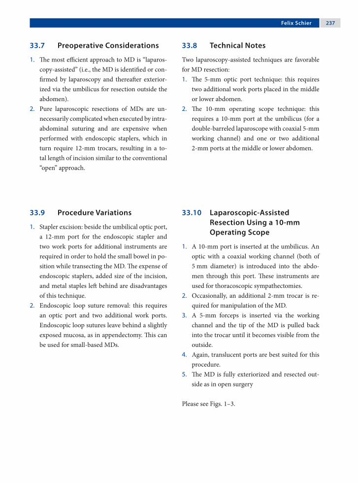
Felix Schier 23�
33.8 Technical Notes
Two laparoscopy-assisted techniques are favorable for MD resection:1. The 5-mm optic port technique: this requires
two additional work ports placed in the middle or lower abdomen.
2. The 10-mm operating scope technique: this requires a 10-mm port at the umbilicus (for a double-barreled laparoscope with coaxial 5-mm working channel) and one or two additional 2-mm ports at the middle or lower abdomen.
33.7 Preoperative Considerations
1. The most efficient approach to MD is “laparos-copy-assisted” (i.e., the MD is identified or con-firmed by laparoscopy and thereafter exterior-ized via the umbilicus for resection outside the abdomen).
2. Pure laparoscopic resections of MDs are un-necessarily complicated when executed by intra- abdominal suturing and are expensive when performed with endoscopic staplers, which in turn require 12-mm trocars, resulting in a to-tal length of incision similar to the conventional “open” approach.
33.9 Procedure Variations
1. Stapler excision: beside the umbilical optic port, a 12-mm port for the endoscopic stapler and two work ports for additional instruments are required in order to hold the small bowel in po-sition while transecting the MD. The expense of endoscopic staplers, added size of the incision, and metal staples left behind are disadvantages of this technique.
2. Endoscopic loop suture removal: this requires an optic port and two additional work ports. Endoscopic loop sutures leave behind a slightly exposed mucosa, as in appendectomy. This can be used for small-based MDs.
33.10 Laparoscopic-Assisted Resection Using a 10-mm Operating Scope
1. A 10-mm port is inserted at the umbilicus. An optic with a coaxial working channel (both of 5 mm diameter) is introduced into the abdo-men through this port. These instruments are used for thoracoscopic sympathectomies.
2. Occasionally, an additional 2-mm trocar is re-quired for manipulation of the MD.
3. A 5-mm forceps is inserted via the working channel and the tip of the MD is pulled back into the trocar until it becomes visible from the outside.
4. Again, translucent ports are best suited for this procedure.
5. The MD is fully exteriorized and resected out-side as in open surgery
Please see Figs. 1–3.

23� Chapter 33 Resection of Meckel’s Diverticulum
Figure 33.1 Figure 33.2
Figure 33.3
A coaxial operating scope is used; occasionally, an additional 2-mm port can be used at the left lower abdominal wall to manipulate the intestines
A 5-mm forceps is passed through the working channel and the MD is grasped back into the trans-lucent port shaft until it is visualized and grabbed from outside
The shaft is removed and the MD is resected as in the “open” technique

Felix Schier 23�
33.11 Laparoscopic-Assisted Resection Using a 5-mm Optic Port
1. A 5-mm port and scope are inserted at the um-bilicus.
2. A suture is attached to the tip of the MD.3. The suture is retracted into the 5-mm umbilical
port (this technique works best with translucent ports).
4. The port is withdrawn, the suture grabbed from outside, and the MD pulled outside the abdom-inal cavity for open resection.
5. In certain cases a single port might be suffi-cient.
Figure 33.4 Figure 33.5
6. At the end of the resection, the bowel might be congested and it may become unexpectedly dif-ficult to reduce it into the abdominal cavity – almost like an incarceration. It therefore is ad-visable not to pull out too much bowel and, if in doubt, the incision should be enlarged in time.
7. In some cases, a 5-mm forceps can be inserted via the working channel and the tip of the MD pulled back into the port until it is becomes vis-ible from outside.
Please see Figs. 4–6.
A suture is placed at the tip of the MD via the two 2-mm ports, after which the 5-mm port at the um-bilicus is removed
The MD is exposed
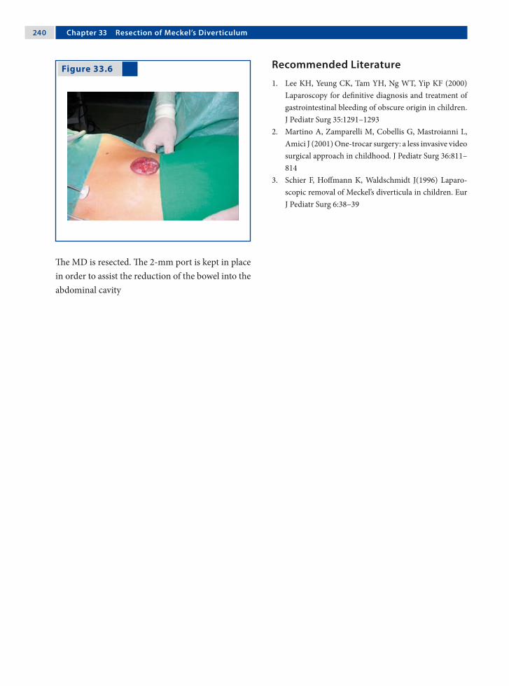
2�0 Chapter 33 Resection of Meckel’s Diverticulum
Figure 33.6 Recommended Literature
1. Lee KH, Yeung CK, Tam YH, Ng WT, Yip KF (2000) Laparoscopy for definitive diagnosis and treatment of gastrointestinal bleeding of obscure origin in children. J Pediatr Surg 35:1291–1293
2. Martino A, Zamparelli M, Cobellis G, Mastroianni L, Amici J (2001) One-trocar surgery: a less invasive video surgical approach in childhood. J Pediatr Surg 36:811–814
3. Schier F, Hoffmann K, Waldschmidt J(1996) Laparo-scopic removal of Meckel’s diverticula in children. Eur J Pediatr Surg 6:38–39
The MD is resected. The 2-mm port is kept in place in order to assist the reduction of the bowel into the abdominal cavity

Surgical Team Position
34.1 Operation Room Setup
34 Intussusception TreatmentJ. Duncan Phillips

2�2 Chapter 3� Intussusception Treatment
Port Placement Sites
34.3 Special Instruments
• Hunter (or other similar) non-traumatic bowel graspers
• Endoscopic loop sutures
34.2 Patient Positioning
Supine position, body elevated on towels or pads, and arms straight out to the sides.
34.4 Location of Access Points

J. Duncan Phillips 2�3
34.5 Indications
1. Nonreduced intussusception.2. Suspected incompletely reduced intussuscep-
tion.3. Suspected intussusception.4. Recurrent intussusception.
34.6 Contraindications
Long-standing intussusception with complete small-bowel obstruction resulting in massive small-bowel distension with subsequent severely limited free space.
34.8 Technical Notes
1. Diagnostic laparoscopy may disclose that com-plete reduction was successful by contrast enema (or may have occurred upon induction of gen-eral anesthesia), thus avoiding laparotomy.
2. Even proof of “partial” reduction is helpful, since this decreases the size of the incision ne-cessary for “open” reduction.
3. Complete reduction may require both ante-grade squeezing of the intestine (“pushing”) and retrograde “pulling” of the intussuscepted intes-tine.
34.7 Preoperative Considerations
1. Attempt reduction with air or liquid contrast enema (if no evidence of peritonitis). Even “par-tial” reduction of intussusception is helpful.
2. Resuscitation with intravenous fluids and anti-biotics if dehydrated.
3. Decompress stomach with nasogastric or oro-gastric tube.
4. Decompress urinary bladder after induction of anesthesia.
5. Prophylactic intravenous antibiotics (if not al-ready given).
34.9 Procedure Variations
1. Laparoscopic verification of incompletely re-duced intussusception, followed by laparotomy for reduction.
2. Laparoscopic verification of infarcted intestine, followed by laparotomy for resection.
3. Laparoscopic-assisted transumbilical reduction and/or resection.
4. Laparoscopic-assisted air (or liquid contrast) enema reduction.
5. Intra-abdominal or extra-abdominal (via port site) appendectomy.
34.10 Laparoscopic Approach to Intussusception
Please see Figs. 1–8.
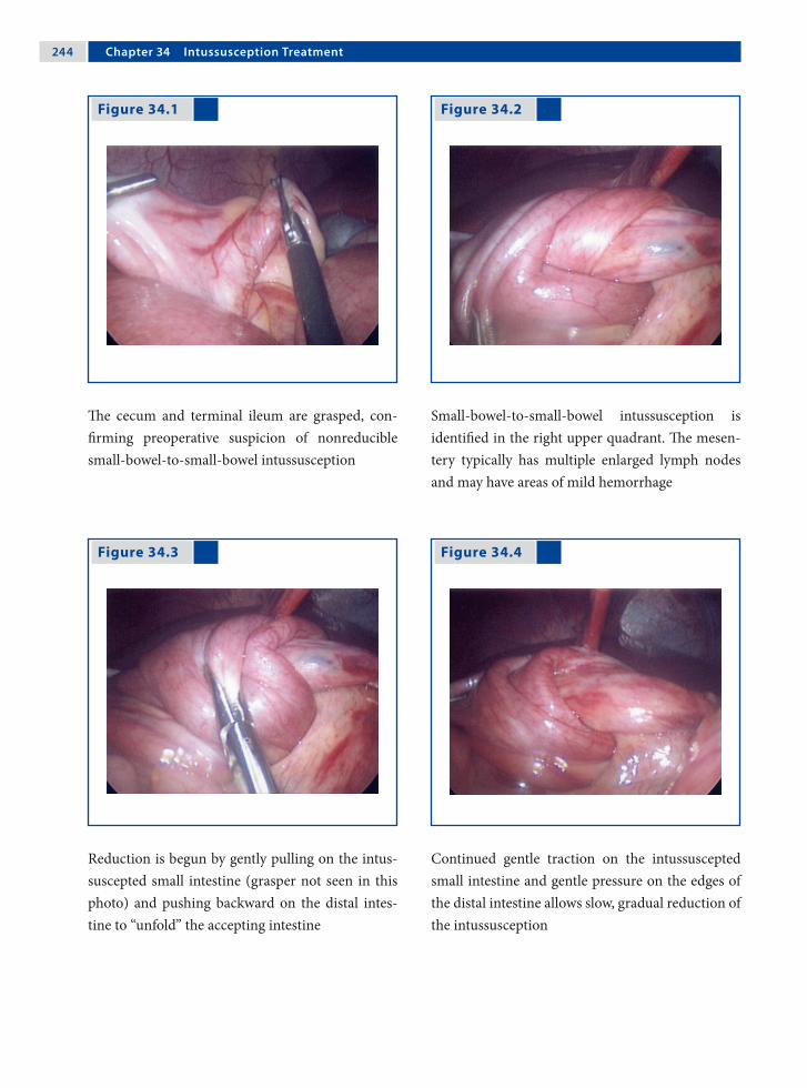
2�� Chapter 3� Intussusception Treatment
Figure 34.1 Figure 34.2
Figure 34.3 Figure 34.4
The cecum and terminal ileum are grasped, con-firming preoperative suspicion of nonreducible small-bowel-to-small-bowel intussusception
Small-bowel-to-small-bowel intussusception is identified in the right upper quadrant. The mesen-tery typically has multiple enlarged lymph nodes and may have areas of mild hemorrhage
Reduction is begun by gently pulling on the intus-suscepted small intestine (grasper not seen in this photo) and pushing backward on the distal intes-tine to “unfold” the accepting intestine
Continued gentle traction on the intussuscepted small intestine and gentle pressure on the edges of the distal intestine allows slow, gradual reduction of the intussusception

J. Duncan Phillips 2��
Figure 34.5 Figure 34.6
Figure 34.7 Figure 34.8
Just prior to complete reduction of the intussuscep-tion, continued gentle traction is applied on the in-tussuscepted intestine
After completed reduction, the segment of intestine is exteriorized through a slightly enlarged umbili-cal incision
Exteriorization allows manual palpation of the af-fected intestinal segment and segmental resection of the “lead point”
Two benign polyps were identified as the “lead points” in the resected intestinal segment

2�� Chapter 3� Intussusception Treatment
Recommended Literature
1. Kia KF, Mony V, Drongowski R, Golladay E, Geiger J, Hirschl R, Coran A, Teitelbaum D (2005) Laparoscopic vs open surgical approach for intussusception requir-ing operative intervention. J Pediatr Surg 40:281–284
2. Poddoubnyi IV, Dronov A, Blinnikov O, Smirnov A, Darenkov I, Dedov K (1998) Laparoscopy in the treat-ment of intussusception in children. J Pediatr Surg 33:1194–1197
3. van der Laan M, Bax NM, van der Zee DC, Ure BM (2001) The role of laparoscopy in the management of childhood intussusception. Surg Endosc 15:373–376

Surgical Team Position
35.1 Operation Room Setup
35 AppendectomyAmulya K. Saxena

2�� Chapter 3� Appendectomy
35.3 Special Instruments
• Endoscopic loop sutures• Bipolar forceps• Specimen retrieval bag
Port Placement Sites
35.2 Patient Positioning
Supine position with arms tucked to the side.
35.4 Location of Access Points

Amulya K. Saxena 2��
35.5 Indications
1. Acute appendicitis.2. Perforated appendicitis.3. Appendicitis with coprolith.4. Retrocecal appendicitis.
35.6 Contraindications
Appendicitis complicated by bowel obstruction with abdominal distension (mesoceliac appendicitis).
35.8 Technical Notes
1. Manipulate the fragile appendix with care. In this case, manipulation using the mesoappendix is recommended.
2. In cases of localized abscess, care should be taken not to burst the abscess. Pus should be as-pirated using a large needle inserted through the abdominal wall under laparoscopic guidance.
3. A preperforative or perforated appendix must be removed from the abdomen in an specimen retrieval bag.
35.7 Preoperative Considerations
1. Leave a povidone iodine gauge in the umbilicus until the patient enters the operating room.
2. Place a Foley catheter before the procedure.3. Preoperative resuscitation should be done if
there are signs of peritonitis.4. In case of suspected perforation, antibiotics
should be administered before general anesthe-sia is induced.
35.9 Procedure Variations
1. Extra-abdominal (laparoscopic-assisted), single- port method (see Chap. 36).
2. Mixed technique (mesoappendix hemostasis performed intra-abdominally and the appen-dix is ligated extra-abdominally), three-port method.
3. Intra-abdominal techniques with:a. Endoscopic stapler.b. Intra-/extracorporeal suturing.
35.10 Laparoscopic Appendectomy
Please see Figs. 1–6.

2�0 Chapter 3� Appendectomy
Figure 35.1 Figure 35.2
Figure 35.3 Figure 35.4
The bowel loops are mobilized and the appendix is lifted using an atraumatic grasper
The vessels of the mesoappendix are coagulated us-ing bipolar forceps
The cauterized mesoappendix is cut using a pair of hooked scissors
Three endoscopic loop sutures are used and the ap-pendix is ligated toward the base

Amulya K. Saxena 2�1
Recommended Literature
1. Gauderer MW (2007) An individualized approach to appendectomy in children based on anatomico-lapa-roscopic findings. Am Surg 73:814–817
2. Saxena AK, Springer A, Tsokas J, Willital GH (2004) Laparoscopic appendectomy in children with Entero-bius vermicularis. Surg Laparosc Endosc Percutan Tech 11:284–286
3. Schmelzer TM, Rana AR, Walters KC, Norton HJ, Bambini DA, Heniford BT (2007) Improved outcomes for laparoscopic appendectomy compared with open appendectomy in the pediatric population. J Laparo-endosc Adv Surg Tech A 17:693–697
Figure 35.5 Figure 35.6
The distal endoscopic loop suture is left uncut and the appendix is cut between it and the two proxi-mal sutures
The distal endoscopic loop suture is used to extract the dissected appendix through the (5-/10-mm) port. Postoperative view of the appendix stump with the two sutures
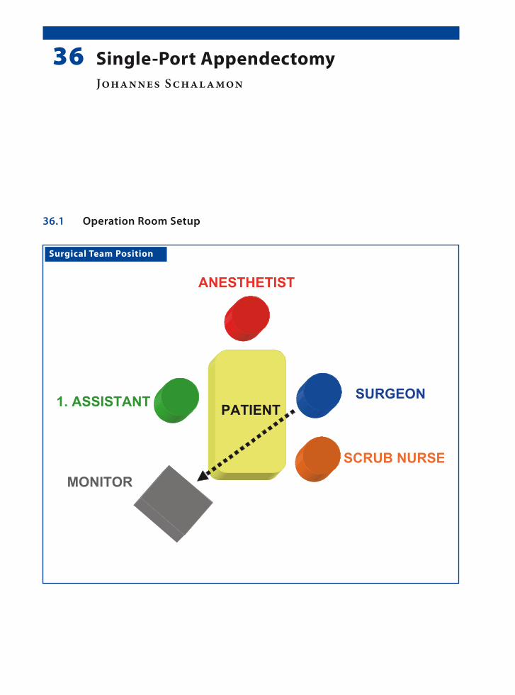
Surgical Team Position
36.1 Operation Room Setup
36 Single-Port AppendectomyJohannes Schalamon

2�� Chapter 3� Single-Port Appendectomy
Port Placement Sites
36.3 Special Instruments
10-mm operating scope with a 5-mm working channel.
36.2 Patient Positioning
Supine position with the arms tucked to the side.
36.4 Location of Access Points
Johannes Schalamon 2��
36.5 Indications
1. Nonperforated appendicitis.2. Phlegmonous appendicitis.3. Appendicitis with impacted stool.4. Obese patients.
36.6 Contraindications
1. Friable appendix.2. Generalized peritonitis after perforation.3. Retrocecal appendicitis.4. Severe adhesions after prior surgery.
36.8 Technical Notes
1. The single-port technique has its limitations in certain forms of appendicitis, where a two-in-strument manipulation may be required.
2. Difficulties arise in the search of Meckel’s diver-ticulum that is not floating and where the intes-tine has to be manipulated.
3. Single-port appendectomy leaves “no” visible skin scars as the scar is concealed in the umbili-cal folds.
36.7 Preoperative Considerations
1. Place a betadine swab in the umbilicus at the point of port insertion.
2. The patient should be draped so that it may also possible to introduce additional ports if deemed necessary.
3. Antibiotic administration depends upon the condition of the appendix and peritoneal in-flammation.
4. The bladder should be drained before com-mencement of the procedure.
36.9 Procedure Variations
1. Single-port appendectomy can be conducted intracorporeally with the aid of a transabdom-inal sling suture.
2. Exteriorization of the inflamed appendix can be performed by insertion of the working scope directly into the right iliac fossa instead of the umbilicus.
3. Right-iliac-fossa appendectomy under local pneumoperitoneum conditions using 12-mm operating scope fitted with a transparent plastic cap.
36.10 Laparoscopic-Assisted Single-Port Appendectomy
Please see Figs. 1–6.

2�� Chapter 3� Single-Port Appendectomy
Figure 36.1 Figure 36.2
Figure 36.3 Figure 36.4
Access is gained into the abdominal cavity using the open-access method
A disposable 10-mm port is inserted and secured to the abdominal wall
The operating scope used has a 6° angle of view and 5-mm instrument channel
A grasper is introduced (left) through the working channel to grasp the appendix (right)

Johannes Schalamon 2��
Recommended Literature
1. D’Alessio A, Piro E, Tadini B, Beretta F (2002) One-trocar transumbilical laparoscopic-assisted appendec-tomy in children: our experience. Eur J Pediatr Surg 12:24–27
2. Koontz CS, Smith L, Burkholder H, Higdon K, Ader-hold R, Carr M (2006) Video-assisted transumbilical appendectomy in children. J Pediatr Surg 41:710–712
3. Ates O, Hakguder G, Olguner M, Akgür F (2007) Single- port laparoscopic appendectomy conducted intracor-poreally with the aid of a transabdominal sling suture. J Pediatr Surg 42:1071–1074
Figure 36.5 Figure 36.6
The grasper, scope, and port are removed as a single unit and the appendix is exteriorized
The appendectomy is performed as in open surgery (left) with good cosmesis (right)

Surgical Team Position
37.1 Operation Room Setup
37 Extramucosal Colon BiopsyCornelia van Tuil and Amulya K. Saxena

2�0 Chapter 3� Extramucosal Colon Biopsy
Port Placement Sites
XX X
Optic port (3.5 / 5 mm)*
Work port (3.5 / 5 mm)*
*Port size depends onthe age of the patient
37.3 Special Instruments
Atraumatic forceps.
37.4 Location of Access Points
37.2 Patient Positioning
Supine position with the arms tucked to the side.

Cornelia van Tuil and Amulya K. Saxena 2�1
37.9 Procedure Variations
1. Full-thickness biopsy procedures can be per-formed using laparoscopic techniques. If the bowel was not prepared before the procedure, this technique has the risk of abdominal con-tamination. This technique also requires sutur-ing of the biopsy site.
2. Single-port laparoscopic-assisted biopsy pro-cedures are performed by retracting the bowel through the umbilical incision using a grasper and then performing an open biopsy.
37.10 Laparoscopic Extramucosal Colon Biopsy
Please see Figs. 1–6.
37.5 Indications
1. Hirschsprung’s disease.2. Neuronal intestinal dysplasia.3. Dysmotility disorders.4. Ganglioneuromatosis.5. Chronic constipation.
37.6 Contraindications
Inflammatory bowel disease is a relative contra-indication.
37.8 Technical Notes
1. The preferred biopsy site is the taenia libera, which is on the antimesenteric side.
2. Grasp only one end and manipulate the speci-men from this freed end. Multiple grasping can damage the specimen.
3. After the specimen is retrieved, control the bi-opsy site for signs of perforation. This finding has to be documented on video for legal rea-sons, because perforations can be sometimes missed under visual inspection.
37.7 Preoperative Considerations
1. Bowel wash outs should be done 24 h before the procedure.
2. Oral laxatives may be necessary in chronic con-stipation patients.
3. Antibiotics are generally not recommended be-fore the procedure, but should be administered if inflammation is suspected.
4. Metronidazole is the antibiotic of choice in Hirschsprungs’s disease.

2�2 Chapter 3� Extramucosal Colon Biopsy
Figure 37.1 Figure 37.2
Figure 37.3 Figure 37.4
The bowel loops are mobilized and the colon is lifted using an atraumatic grasper
While holding the colon under tension, an incision is made in the serosa using Metzenbaum scissors
The incision on the antimesenteric side avoids ves-sels that cross the other two taenia
The free end of the biopsy is grasped to expose the plane between the mucosa and serosa
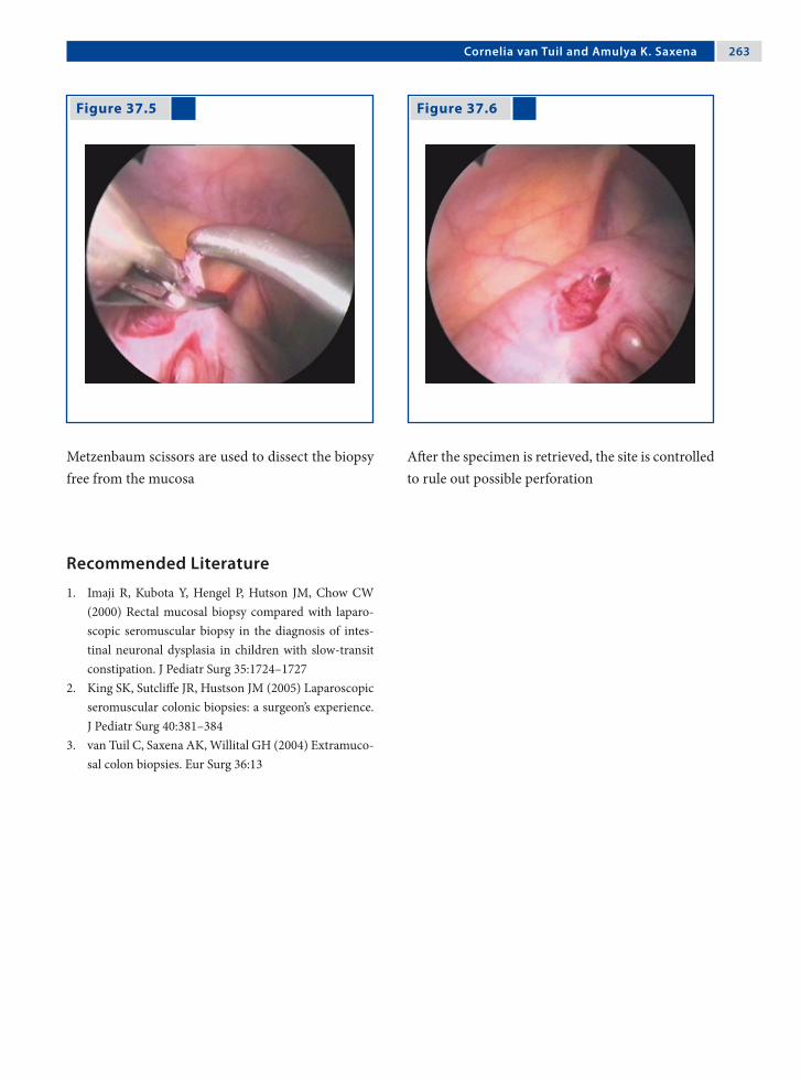
Cornelia van Tuil and Amulya K. Saxena 2�3
Recommended Literature
1. Imaji R, Kubota Y, Hengel P, Hutson JM, Chow CW (2000) Rectal mucosal biopsy compared with laparo-scopic seromuscular biopsy in the diagnosis of intes-tinal neuronal dysplasia in children with slow-transit constipation. J Pediatr Surg 35:1724–1727
2. King SK, Sutcliffe JR, Hustson JM (2005) Laparoscopic seromuscular colonic biopsies: a surgeon’s experience. J Pediatr Surg 40:381–384
3. van Tuil C, Saxena AK, Willital GH (2004) Extramuco-sal colon biopsies. Eur Surg 36:13
Figure 37.5 Figure 37.6
Metzenbaum scissors are used to dissect the biopsy free from the mucosa
After the specimen is retrieved, the site is controlled to rule out possible perforation

Surgical Team Position
38.1 Operation Room Setup
38 Total Colectomy with Pelvic PouchIvan R. Diamond and Jacob C. Langer

2�� Chapter 3� Total Colectomy with Pelvic Pouch
38.3 Special Instruments
• LigaSure™ (Valleylab, Boulder, CO, USA)• Endo GIA™ stapler (Auto Suture, Norwalk, CT,
USA)• Circular end-to-end anastomosis (EEA) stapler• Typically 12mm ports are used at umbilicus and
in the right lower quadrant at the position de-termined to be optimal for the ileostomy.
Port Placement Sites
Optic port 12 mm
Work port (5 / 10 mm)*
Work port 12 mm
*Port size depends onthe age of the patient
XX
XX
38.4 Location of Access Points
38.2 Patient Positioning
Supine position with arms tucked to the side for the initial portion of the procedure. Move to the lithot-omy position at the conclusion of the rectal dissec-tion for pouch–anal anastomosis.

Ivan R. Diamond and Jacob C. Langer 2��
38.5 Indications
1. Ulcerative colitis:a. Refractory to medical treatment.b. Complication of medical therapy.c. Dysplasia/malignancy (rare in children).
2. Familial adenomatous polyposis (FAP).
38.6 Contraindications
1. Absolute contraindication: Crohn’s disease2. Relative contraindication
a. Very young child.b. Indeterminate colitis.c. Patient who is sick, malnourished, or on
chronic high-dose steroids.
38.8 Technical Notes
1. Perform the initial diagnostic laparoscopy to ensure that there is no evidence of Crohn’s dis-ease.
2. Creation of a small (8–10 cm) pouch is optimal to the minimize risk of pouchitis.
3. When anastomosing the pouch, take care to en-sure that there is no torsion of the pouch mes-entery.
4. Plan to close the loop-ileostomy after 6 weeks or longer, preceded by a contrast study of the pouch.
38.7 Preoperative Considerations
1. Bowel preparation in the absence of severe acute colitis.
2. Place a Foley catheter and a nasogastric tube be-fore the procedure.
3. Administer prophylactic antibiotics.4. Administer steroids perioperatively if the pa-
tient is on current or has had recent steroid treatment.
38.9 Procedure Variations
1. Three-stage procedure consisting of: (a) subto-tal colectomy, (b) formation of a pelvic pouch, and (c) ileostomy closure in malnutrition, pro-longed steroid use, severe acute colitis, or the very young child. Alternatively, the identical initial operation with two modifications: (a) a more distal division of the sigmoid colon; and (b) temporary end-ileostomy rather than the il-eal-pouch.
2. “One-step” procedure without protecting the loop ileostomy in FAP.
3. Laparoscopic-assisted procedure with low transverse incision (Pfannenstiel) for rectal dis-section and pouch creation.
38.10 Laparoscopic Total Colectomy with Pelvic Pouch
Please see Figs. 1–12.

2�� Chapter 3� Total Colectomy with Pelvic Pouch
Figure 38.1 Figure 38.2
Figure 38.3 Figure 38.4
A window is made in the sigmoid mesentery and the sigmoid colon is divided using the EndoGIA™ stapler
The lateral attachments of the descending colon are mobilized using the electrocautery
Starting from the sigmoid colon and moving from distal to proximal toward the right colon, the co-lonic mesentery is divided using the LigaSure™ de-vice
The colon is extracted through the right lower quadrant port site, and resected by using the Endo-GIA™ stapler to divide the ileum. If the pouch is to be created at a second operation, an end-ileostomy is sited at this time

Ivan R. Diamond and Jacob C. Langer 2��
Figure 38.5 Figure 38.6
Figure 38.7 Figure 38.8
The ileal pouch is created using the EndoGIA™ sta-pler; the anvil from the EEA stapler is placed using a polypropylene purse-string suture
Once the pouch is returned to the abdomen, the right lower quadrant port site is closed by place-ment of a Hasson trocar
Starting from the sigmoid stump, the dissection of the rectosigmoid is completed using the LigaSure™ for the mesentery, and the electrocautery to divide the peritoneal reflection
Dissection of the rectum is continued down to the pelvic floor, taking great care to stay immediately on the rectal wall. At this point the patient is placed in the lithotomy position to facilitate pouch–anal anastomosis

2�0 Chapter 3� Total Colectomy with Pelvic Pouch
Figure 38.9 Figure 38.10
Using a Babcock forceps placed into the rec-tum, the rectal stump is everted. The specimen is then resected 1 cm above the dentate line using an EndoGIA™ stapler. This avoids interference with the transitional mucosa that is important in main-taining continence, and also avoids leaving an ex-cessive amount of rectal mucosa
The circular EEA stapler is advanced through the anus at the top of the staple line, with laparoscopic visualization

Ivan R. Diamond and Jacob C. Langer 2�1
Recommended Literature
1. Georgeson KE (2002) Laparoscopic-assisted total col-ectomy with pouch reconstruction. Semin Pediatr Surg 11:233–236
2. Kienle P, Zgraggen K, Schmidt J, Benner A, Weitz J, Buchler MW (2005) Laparoscopic restorative procto-colectomy. Br J Surg 92:88–93
3. Proctor ML, Langer JC, Gerstle JT, Kim PC (2002) Is laparoscopic subtotal colectomy better than open sub-total colectomy in children? J Pediatr Surg 37:706–708
Figure 38.11 Figure 38.12
The pouch is advanced to the EEA stapler and anas-tomosed to the anus under direct laparoscopic visu-alization. The staple lines can be tested by filling the pelvis with saline and gently blowing air into the pouch. If there is a small leak, a drain can be placed into the pelvis through the left lower quadrant lap-aroscopic port site
A loop ileostomy is sited at the right lower quad-rant port site
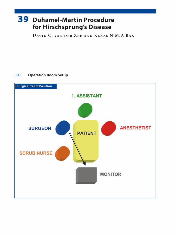
Surgical Team Position
39.1 Operation Room Setup
39 Duhamel-Martin Procedure for Hirschsprung’s DiseaseDavid C. van der Zee and Klaas N.M.A Bax

2�� Chapter 3� Duhamel-Martin Procedure for Hirschsprung’s Disease
Port Placement Sites
39.3 Special Instruments
Endo GIA™ stapler (Auto Suture, Norwalk, CT, USA).
39.2 Patient Positioning
Supine position and placed transverse on a short operating table. The surgeon is standing at the up-per right side of the patient.
39.4 Location of Access Points

David C. van der Zee and Klaas N.M.A Bax 2��
39.8 Technical Notes
1. Always place a suture over the biopsy site to avoid contamination.
2. When using monopolar diathermy, care should be taken not to cause collateral damage to the intestines and the vas deferens.
3. Precaution should be taken not to twist the in-testine when pulling through.
4. Where the patient has an enterostomy, this can be closed during this procedure.
39.7 Preoperative Considerations
1. Antegrade intestinal washout should be per-formed on the day prior to surgery.
2. Repeat the rectal washout on the operating table before commencement of the procedure.
3. Drape the patient in such a way so that his/her legs can be maneuvered up and down.
4. Place a urine catheter after draping.5. Perioperative antibiotics should be adminis-
tered.
39.9 Procedure Variations
1. Instead of ligating and transecting the colon be-fore pulling through, the intestine can also be exvaginated transanally and transected extra-corporeally.
2. In the case of extended Hirschsprung’s disease a somewhat longer rectal stump can be left in place with a side-to-side anastomosis, as re-ported by Duhamel-Martin.
39.10 Laparoscopic Duhamel-Martin Procedure
Please see Figs. 1–11.
39.5 Indications
1. Hirschsprung’s disease.2. Extended Hirschsprung’s disease.
39.6 Contraindications
None.

2�� Chapter 3� Duhamel-Martin Procedure for Hirschsprung’s Disease
Figure 39.1 Figure 39.2
The first step is to take extramucosal biopsy samples and to determine the level of aganglionosis. Usu-ally one sample is taken from the transition zone and one from the more proximal “normal-looking” bowel
After confirmation of the frozen section by the pa-thologist, the mesentery is dissected close to the bowel, from the pelvic floor up to the site of the most proximal biopsy

David C. van der Zee and Klaas N.M.A Bax 2� �
Figure 39.3 Figure 39.4
A ligature is placed around the dissected bowel to avoid spillage during the pull-through
The distal rectum is cleaned and residual contents are aspirated again before the bowel is transected

2�� Chapter 3� Duhamel-Martin Procedure for Hirschsprung’s Disease
Figure 39.5 Figure 39.6
Figure 39.7 Figure 39.8
The anal phase is started with incision of the poste-rior wall of the rectum 0.5 cm proximal to the den-tate line. Stay-sutures are placed at the anterior side of the incision and at the lateral corners for trac-tion
A grasping clamp is attached to a pulled-through endoscopic instrument and introduced into the ab-domen
The transected colon (up to the level of the proxi-mal biopsy sampling point) is pulled out through the posterior opening in the anus under close endo-scopic control so that the bowel does not twist
The bowel is resected at this point. After trimming, the pulled-through bowel is anastomosed to the anus

David C. van der Zee and Klaas N.M.A Bax 2��
Figure 39.9 Figure 39.10
Keeping the stay-sutures under traction, an En-doGIA™ stapler can be introduced with one leg in the “old” rectum and one leg in the pulled-through bowel
Under endoscopic control, the right position of the EndoGIA™ stapler can be determined before firing the device. Usually two cartridges are necessary to complete the side-to-side anastomosis

2�0 Chapter 3� Duhamel-Martin Procedure for Hirschsprung’s Disease
Figure 39.11 Recommended Literature
1. Travassos DV, Bax NM, van der Zee DC (2007) Du-hamel procedure: a comparative retrospective study between an open and a laparoscopic technique. Surg Endosc 21:2163–2165
2. Mattioli G, Castagnetti M, Martucciello G, Jassoni V (2004) Results of a mechanical Duhamel pull-through for the treatment of Hirschsprung’s disease and intesti-nal neuronal dysplasia. J Pediatr Surg 39:1349–1355
3. Minford JL, Ram A, Turnock RR, Lamont GL, Kenny SE, Rintala RJ, Lloyd DA, Baillie CT (2004) Comparison of functional outcomes of Duhamel and transanal en-dorectal coloanal anastomosis for Hirschsprung’s dis-ease. J Pediatr Surg 39:161–165
Finally, the rectal stump can be closed using one or two running sutures. If necessary, the stump can be trimmed to an appropriate size before closure

Surgical Team Position
40.1 Operation Room Setup
40 Pull-Through for High Imperforate AnusMario Lima and Stefano Tursini
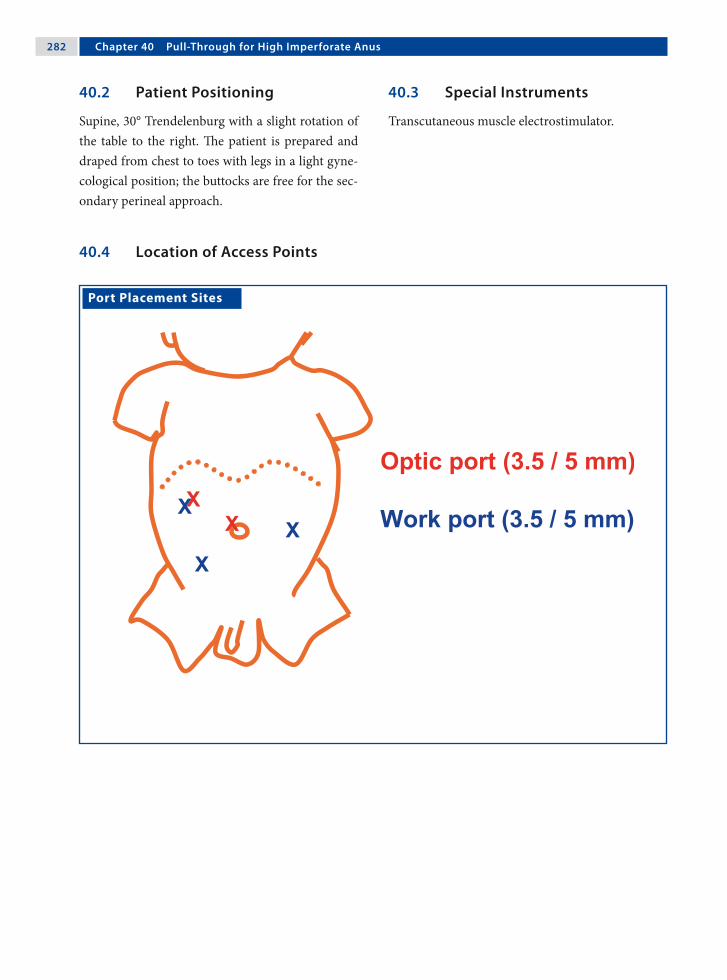
2�2 Chapter �0 Pull-Through for High Imperforate Anus
40.3 Special Instruments
Transcutaneous muscle electrostimulator.
Port Placement Sites
40.2 Patient Positioning
Supine, 30° Trendelenburg with a slight rotation of the table to the right. The patient is prepared and draped from chest to toes with legs in a light gyne-cological position; the buttocks are free for the sec-ondary perineal approach.
40.4 Location of Access Points
Mario Lima and Stefano Tursini 2�3
40.5 Indications
High imperforate anus in males or females either with fistula or without fistula.
40.6 Contraindications
General contraindications to laparoscopic surgery.
40.7 Technical Notes
1. The (3-mm) optic is positioned in the umbili-cus. After the operative ports are inserted, the (5-mm) optic is moved to the right.
2. Precaution should be taken with colostomy po-sitioning. A short distal pouch is difficult to pull through.
3. The fistula should be dissected and sectioned as distally as possible. It is preferably closed with a transfix suture. It is also recommended to leave a urethral tutor in place.
4. Mapping of the perineal area with a transcuta-neous muscle electrostimulator is mandatory.
5. The laparoscopic view confirms the passage of the pull-through between the bellies of the pu-bococcygeus muscles.
40.8 Preoperative Considerations
1. A left-loop colostomy is performed at birth.2. Decompression of the sigmoid tract is an ad-
vantage; it can allow an accurate evaluation of the fistula.
3. Associated malformations should be studied ac-curately.
4. The bladder should be empty (catheterization or Credé’s maneuver).
40.9 Procedure Variations
1. Single-stage procedure without a diverting col-ostomy.
2. Veress needle is an option for pneumoperito-neum.
3. The bladder can be elevated using a transfix su-ture to the anterior abdominal plane.
4. A clip can be used to close the fistula distally.5. Alternatively, the distal fistula can be left open
with a urethral tutor.
40.10 Laparoscopic Step – Anorectal Pullthrough
Please see Figs. 1–6.

2�� Chapter �0 Pull-Through for High Imperforate Anus
Figure 40.1 Figure 40.2
Figure 40.3 Figure 40.4
The patient in positioned in a 30° supine position. The optic is moved from the umbilicus to the right
The peritoneum is opened and dissected to reach the fistula
The fistula is located and grasped and the vessels are exposed and dissected with a monopolar hook
After careful dissection, the fistula is clearly ex-posed

Mario Lima and Stefano Tursini 2��
Figure 40.5 Figure 40.6
Ligation of the fistula is performed as distally as possible with a transfix absorbable suture
Scissors are used to section the ligated fistula

2�� Chapter �0 Pull-Through for High Imperforate Anus
40.11 Perineal Step – Anorectal Pullthrough
40.11.1 Patient Position
Supine with legs in a light gynecological position to expose the perineal plane. The surgeon moves to the perineal plane.
Please see Figs. 7–13.
Surgical Team Position

Mario Lima and Stefano Tursini 2��
Figure 40.7 Figure 40.8
Figure 40.9 Figure 40.10
Mapping of the perineal area is performed with an transcutaneous muscle electrostimulator. The cen-ter of maximum contraction and cephalad eleva-tion is identified as the location of the new-anus
The pubococcygeus bellies are identified using a laparoscopic muscle electrostimulator with the cur-rent at an intensity of 60 mA
A vertical incision is made in the perineal area and a trocar is passed through the defined plane in the external sphincter muscle complex
The trocar is advanced into the pelvis between the bellies of the pubococcygeus muscles

2�� Chapter �0 Pull-Through for High Imperforate Anus
Recommended Literature
1. Georgeson KE, Inge TH, Albanese CT (2000) Lapa-roscopically assisted anorectal pull-through for high imperforate anus – a new technique. J Pediatr Surg 35:927–930
2. Iwanaka T, Arai M, Kawashima H, Kudou S, Fujishiro J, Matsui A, Imaizumi S (2003) Findings of pelvic mus-culature and efficacy of laparoscopic muscle stimula-tor in laparoscopy-assisted anorectal pull-through for high imperforate anus. Surg Endosc 17:278–281
3. Lima M, Tursini S, Ruggeri G, Aquino A, Gargano T, De Biagi L, Ahmed A, Gentili A (2006) Laparoscopi-cally assisted anorectal pull-through for high imperfo-rate anus: three years experience. J Laparoendosc Adv Surg Tech A 16:63–66
Figure 40.11 Figure 40.12
Figure 40.13
View of the “perineal” trocar at the point of inser-tion
The rectal fistula is grasped and pulled through the incision to be exteriorized to the perineum
The rectum is sutured to the anus with interrupted 4-0 absorbable suture (Vicryl™; Ethicon, Somer-ville, NJ, USA)

41.1 Operation Room Setup
Surgical Team Position
41 RectopexyMunther J. Haddad and Amulya K. Saxena

2�0 Chapter �1 Rectopexy
Port Placement Sites
41.3 Special Instruments
Polypropylene mesh.
41.2 Patient Positioning
Supine position with arms tucked to the side.
41.4 Location of Access Points

Munther J. Haddad and Amulya K. Saxena 2�1
41.5 Indications
Severe rectal prolapse after failure of conservative management in:1. Cystic fibrosis.2. Chronic constipation.3. Juvenile polyp (rare).
41.6 Contraindications
No absolute contraindication; however, only after failure of conservative therapy.
41.8 Technical Notes
1. Precaution must be taken when dissecting through the mesentery.
2. Care should be taken not to injure the ureters or the iliac vessels.
3. The sacral promontory, which is covered by a fascia, can be palpated as a hard, bone-like structure through which the sutures are placed.
4. Two sutures placed on either side of the colon must be placed at a distance of at least 2 cm from each other.
41.7 Preoperative Considerations
1. Bowel preparation is important to debulk the colon prior to surgery.
2. Preoperative antibiotics are administered: cefu-roxime (30 mg/kg).
3. A nasogastric tube is placed to allow gastric de-compensation.
4. A Foley catheter is placed for bladder drainage.
41.9 Procedure Variations
1. A polypropylene mesh is tacked to the presacral fascia under the colon with the aid of a hernia stapler. Care must be taken that the staples do not penetrate into the lumen of the bowel.
2. The retracted sigma colon is sutured to the left psoas muscle using nonabsorbable suture mater-ials.
3. Perform a simple suture rectopexy with nonab-sorbable sutures to secure the colon to the pre-sacral fascia.
41.10 Laparoscopic Rectopexy Using Polypropylene Mesh
Please see Figs. 1–6.

2�2 Chapter �1 Rectopexy
Figure 41.1 Figure 41.2
Figure 41.3 Figure 41.4
The rectosigmoid colon is retracted and the perito-neum is opened to facilitate sacral exposure
The peritoneum is incised circumferentially and care is take to avoid injury to the rectal vessels
A grasper is passed behind the colon and a strip of polypropylene mesh is grasped and retrieved
The polypropylene mesh is then wrapped around the rectum with the free end held upward
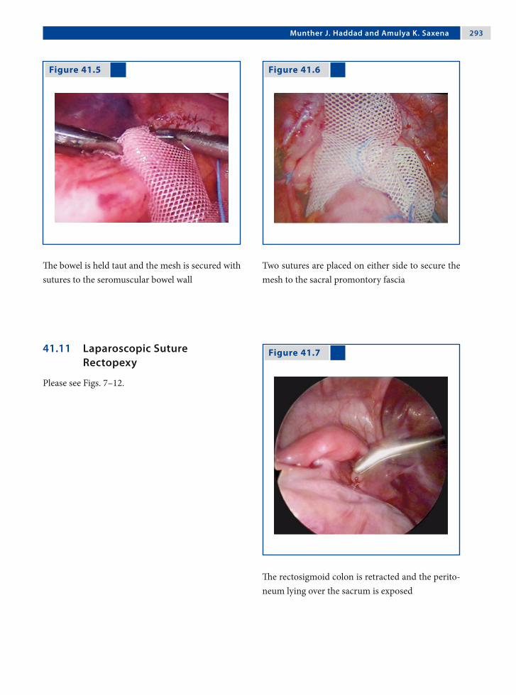
Munther J. Haddad and Amulya K. Saxena 2�3
Figure 41.5 Figure 41.6
Figure 41.7 41.11 Laparoscopic Suture Rectopexy
Please see Figs. 7–12.
The bowel is held taut and the mesh is secured with sutures to the seromuscular bowel wall
Two sutures are placed on either side to secure the mesh to the sacral promontory fascia
The rectosigmoid colon is retracted and the perito-neum lying over the sacrum is exposed

2�� Chapter �1 Rectopexy
Figure 41.8 Figure 41.9
Figure 41.10 Figure 41.11
The peritoneum is raised and incised. This can be done using Metzenbaum scissors; electrocautery is not required
While the presacral facia is being exposed, care should be taken to identify the iliac vessels and the ureter
A nonabsorbable suture is passed through the pre-sacral promontory fascia
The bowel is held taut and the same suture is passed through the seromuscular layer of the rectosigmoid colon and the knot is tied

Munther J. Haddad and Amulya K. Saxena 2��
Recommended Literature
1. Bonnard A, Mougenot JP, Ferkdadji L, Huot O, Aigrain Y, De Lagausie P (2003) Laparoscopic rectopexy for solitary ulcer of rectum syndrome in a child. Surg En-dosc 17:1156–1157
2. Koivusalo A, Pakarinen M, Rintala R (2006) Laparo-scopic suture rectopexy in the treatment of persisting rectal prolapse in children: a preliminary report. Surg Endosc 20:960–963
3. Saxena AK, Metzelder ML, Willital GH (2004) La-paroscopic suture rectopexy for rectal prolapse in a 22-month-old child. Surg Laparosc Endosc Percutan Tech 14:33–34
Figure 41.12
Two sutures are placed on either side to secure the rectosigmoid colon to the sacral promontory fascia

Surgical Team Position
42.1 Operation Room Setup
42 Ventriculoperitoneal Shunt ImplantationAmulya K. Saxena and Hans G. Eder

2�� Chapter �2 Ventriculoperitoneal Shunt Implantation
Port Placement Sites
42.3 Special Instruments
Ventriculoperitoneal shunt system.
42.2 Patient Positioning
Supine position with arms tucked to the side.
42.4 Location of Access Points

Amulya K. Saxena and Hans G. Eder 2��
42.5 Indications
Communicating and noncommunicating forms of hydrocephalus in:1. Intraventricular hemorrhage.2. Inflammation.3. Neoplastic diseases.4. Congenital malformations.5. Trauma-associated conditions.6. Special indication is severe adhesions after prior
abdominal surgery.
42.6 Relative Contraindications
Severe central nervous system malformations.
42.8 Technical Notes
1. Care is taken to minimize handling of the shunt throughout the entire surgical procedure.
2. In the case of abdominal adhesions, two ports are introduced and the adhesions are removed using conventional laparoscopic methods.
3. Using a port (peel-away sheath) to insert the shunt in the abdomen prevents direct contact of the shunt with the abdominal skin. Use of skin foil is also recommended.
4. The scope should control the placement and flow of the shunt before closure.
42.7 Preoperative Considerations
1. The patient is draped with the head and neck ex-posed on the side that the shunt is to be placed. The abdomen, however, is draped in a fashion suitable for abdominal procedures.
2. Consider rifampicin- or clindamycin-impreg-nated silicone shunts in complicated cases.
3. Antibiotics may be administered preopera-tively.
4. Efforts should be taken to avoid hypothermia during surgery in infants.
5. The scalp is shaved at the site of intended cathe-ter placement.
42.9 Procedure Variations
1. The abdominal portion of the procedure can be performed using a 5-mm trocar and a 10-Fr in-troducer for camera and catheter insertion.
2. Under laparoscopic control, a needle is intro-duced through a 5-mm incision in the right upper quadrant and the shunt tubing is tun-neled to that site. A J-tipped guide wire is intro-duced, and the needle is exchanged for a dila-tor and peel-away sheath. The shunt is delivered through the sheath, which is sectioned and re-moved.
42.10 Laparoscopic-Assisted Ventriculoperitoneal Shunt Implantation
Please see Figs. 1–3.

300 Chapter �2 Ventriculoperitoneal Shunt Implantation
Figure 42.1 Figure 42.2
After insertion of the optic port, the shunt peel-away sheath is inserted directly through the ab-dominal wall under visual guidance
The final location of the shunt is controlled after the shunt peel-away sheath is removed
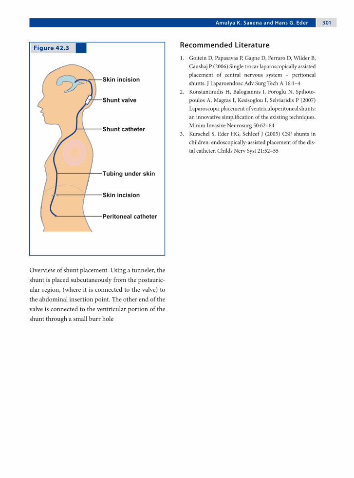
Amulya K. Saxena and Hans G. Eder 301
Recommended Literature
1. Goitein D, Papasavas P, Gagne D, Ferraro D, Wilder B, Caushaj P (2006) Single trocar laparoscopically assisted placement of central nervous system – peritoneal shunts. J Laparoendosc Adv Surg Tech A 16:1–4
2. Konstantinidis H, Balogiannis I, Foroglu N, Spilioto-poulos A, Magras I, Kesisoglou I, Selviaridis P (2007) Laparoscopic placement of ventriculoperitoneal shunts: an innovative simplification of the existing techniques. Minim Invasive Neurosurg 50:62–64
3. Kurschel S, Eder HG, Schleef J (2005) CSF shunts in children: endoscopically-assisted placement of the dis-tal catheter. Childs Nerv Syst 21:52–55
Figure 42.3
Overview of shunt placement. Using a tunneler, the shunt is placed subcutaneously from the postauric-ular region, (where it is connected to the valve) to the abdominal insertion point. The other end of the valve is connected to the ventricular portion of the shunt through a small burr hole
Section 4 Hepatobiliary, Splenic and Pancreatic Procedures

Surgical Team Position
43.1 Operation Room Setup
43 CholecystectomyMichael E. Höllwarth
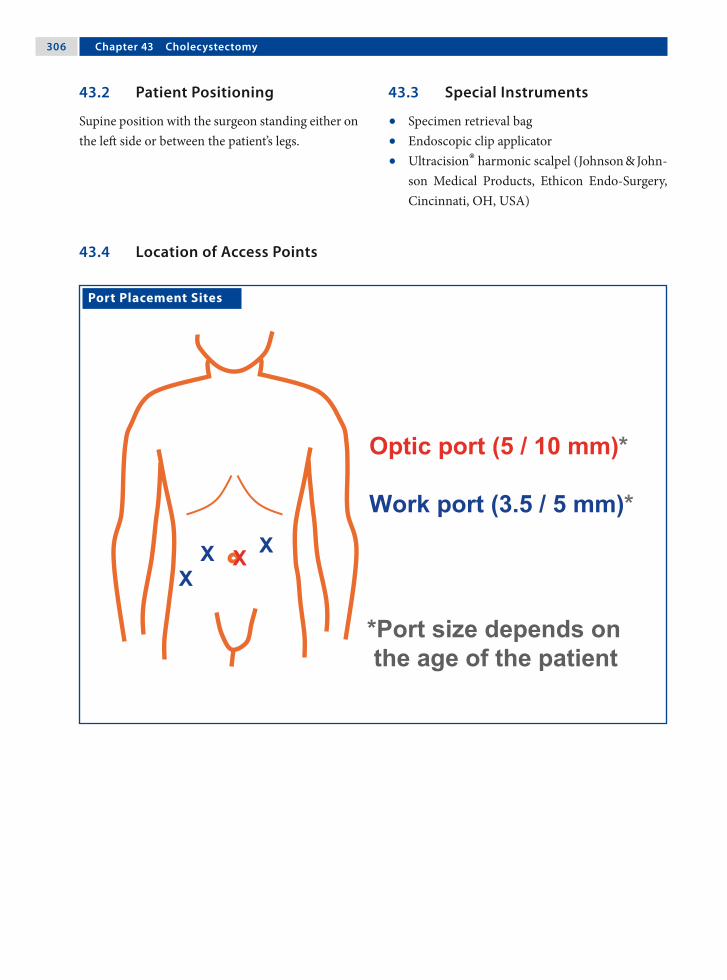
30� Chapter �3 Cholecystectomy
Port Placement Sites
43.3 Special Instruments
• Specimen retrieval bag• Endoscopic clip applicator• Ultracision® harmonic scalpel (Johnson & John-
son Medical Products, Ethicon Endo-Surgery, Cincinnati, OH, USA)
43.2 Patient Positioning
Supine position with the surgeon standing either on the left side or between the patient’s legs.
43.4 Location of Access Points
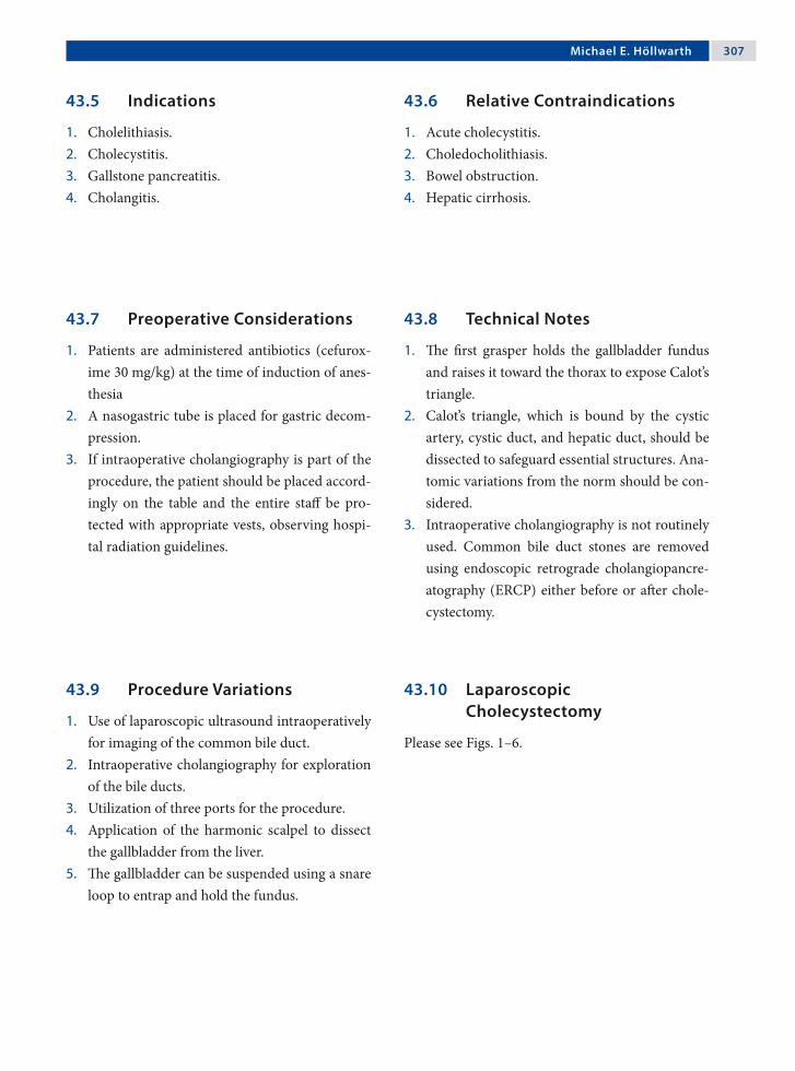
Michael E. Höllwarth 30�
43.5 Indications
1. Cholelithiasis.2. Cholecystitis.3. Gallstone pancreatitis.4. Cholangitis.
43.6 Relative Contraindications
1. Acute cholecystitis.2. Choledocholithiasis.3. Bowel obstruction.4. Hepatic cirrhosis.
43.8 Technical Notes
1. The first grasper holds the gallbladder fundus and raises it toward the thorax to expose Calot’s triangle.
2. Calot’s triangle, which is bound by the cystic artery, cystic duct, and hepatic duct, should be dissected to safeguard essential structures. Ana-tomic variations from the norm should be con-sidered.
3. Intraoperative cholangiography is not routinely used. Common bile duct stones are removed using endoscopic retrograde cholangiopancre-atography (ERCP) either before or after chole-cystectomy.
43.7 Preoperative Considerations
1. Patients are administered antibiotics (cefurox-ime 30 mg/kg) at the time of induction of anes-thesia
2. A nasogastric tube is placed for gastric decom-pression.
3. If intraoperative cholangiography is part of the procedure, the patient should be placed accord-ingly on the table and the entire staff be pro-tected with appropriate vests, observing hospi-tal radiation guidelines.
43.9 Procedure Variations
1. Use of laparoscopic ultrasound intraoperatively for imaging of the common bile duct.
2. Intraoperative cholangiography for exploration of the bile ducts.
3. Utilization of three ports for the procedure.4. Application of the harmonic scalpel to dissect
the gallbladder from the liver.5. The gallbladder can be suspended using a snare
loop to entrap and hold the fundus.
43.10 Laparoscopic Cholecystectomy
Please see Figs. 1–6.
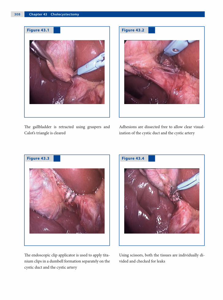
30� Chapter �3 Cholecystectomy
Figure 43.1 Figure 43.2
Figure 43.3 Figure 43.4
The gallbladder is retracted using graspers and Calot’s triangle is cleared
Adhesions are dissected free to allow clear visual-ization of the cystic duct and the cystic artery
The endoscopic clip applicator is used to apply tita-nium clips in a dumbell formation separately on the cystic duct and the cystic artery
Using scissors, both the tissues are individually di-vided and checked for leaks

Michael E. Höllwarth 30�
Recommended Literature
1. Bonnard A, Seguier-Lipszyc E, Liguory C, Benker-rou M, Garel C, Malbezin S, Aigrain Y, de Lagausie P (2005) Laparoscopic approach as primary treatment of common bile duct stones in children. J Pediatr Surg 40:1459–1463
2. Callery MP (2006) Avoiding biliary injury during laparoscopic cholecystectomy: technical consider-ations. Surg Endosc 20:1654–1658
3. Zacharakis E, Angelopoulos S, Kanellos D, Prame-teftakis MG, Sapidis N, Stamatopolous H, Kanellos I, Tsalis K, Betsis D (2007) Laparoscopic cholecystec-tomy without intraoperative cholangiography. J Lapa-roendosc Adv Surg Tech A 17:620–625
Figure 43.5 Figure 43.6
The gallbladder is dissected using electrosurgical bipolar scissors from the cystic duct end
After the gallbladder is dissected free, it is either extracted through a 10-mm port or placed into a specimen retrieval bag and removed

Surgical Team Position
44.1 Operation Room Setup
44 Liver BiopsyKiyokazu Nakajima, Hideki Soh and Toshirou Nishida

312 Chapter �� Liver Biopsy
Port Placement Sites
44.3 Special Instruments
None.
44.2 Patient Positioning
Supine position with arms tucked to the side. Right side up with mild reverse Trendelenburg position if needed.
44.4 Location of Access Points

Kiyokazu Nakajima, Hideki Soh, and Toshirou Nishida 313
44.5 Indications
1. Liver disorders of unknown origin, especially cases with failed diagnosis by percutaneous core-needle biopsy.
2. Staging of chronic hepatitis following serologic diagnosis.
44.6 Contraindications
1. Severe bleeding diathesis.2. Severe liver cirrhosis.
44.8 Technical Notes
1. Evaluate the feasibility of hepatic clamping be-fore starting the excision.
2. If the tissue is too cirrhotic to clamp, consider a core-needle biopsy procedure carried out under laparoscopic guidance.
3. A suction/irrigation line should be kept opera-tional during the procedure.
4. Insertion of surgical gauze or sponge can be per-formed if a full-size laparoscopic port is avail-able. Use of these materials greatly facilitates the procedure.
44.7 Preoperative Considerations
1. The severity of hepatic damage should be evalu-ated fully prior to surgery.
2. Standard preoperative management should be carried out (e.g., draping, bladder emptying, an-tibiotics prophylaxis).
3. When concomitant abdominal surgery is planned, consideration of the accompanying procedure must also be taken into account.
44.9 Procedure Variations
1. In adolescent patients, laparoscopic “stapled” wedge biopsy using Endo GIA™ stapler (Auto Suture, Norwalk, CT, USA) is optional. Use vas-cular cartridges to secure hemostasis.
2. A core-needle biopsy can be performed under laparoscopic guidance. Hemostasis is easily ob-tained at the biopsy site with the aid of electro-coagulation.
3. Laparoscopic ultrasound is optional to mini-mize perforation injury to major intrahepatic structures.
44.10 Laparoscopic Liver Wedge Biopsy
Please see Figs. 1–6.

31� Chapter �� Liver Biopsy
Figure 44.1 Figure 44.2
Figure 44.3 Figure 44.4
Two atraumatic bowel graspers are placed on the liver edge at a 90° angle
The hepatic tissue is tentatively clamped. Note the ischemic wedge between the two graspers, indicat-ing effective clamping
A curved endoscopic scissors is introduced while the graspers are held in situ by the assistant
The tissue is excised between the two graspers. Bleeding is minimal when clamping is successful

Kiyokazu Nakajima, Hideki Soh, and Toshirou Nishida 31�
Recommended Literature
1. Lefor AT, Flowers JL (1994) Laparoscopic wedge bi-opsy of the liver. J Am Coll Surg 178:307–308
2. Nakajima K, Neze R, Sakamoto T, Suguira F, Yama-mura N, Ito T, Nishida T (2007) A simple technique for wedge biopsy of the liver during laparoscopic surgery. J Laparoendosc Adv Surg Tech A 17:470–472
3. Sheela H, Seela S, Caldwell C, Boyer JL, Jain D (2005) Liver biopsy: evolving role in the new millennium. J Clin Gastroenterol 39:603–610
Figure 44.5 Figure 44.6
The specimen is retrieved using tissue-extracting forceps
The cut surfaces are coagulated with monopolar forceps. Additional coagulation is performed if any bleeding is noted after partial declamping

Surgical Team Position
45.1 Operation Room Setup
45 Choledochal Cyst ResectionRamin Jamshidi and Hanmin Lee

31� Chapter �� Choledochal Cyst Resection
Port Placement Sites
45.3 Special Instruments
None.
45.2 Patient Positioning
The patient is positioned supine at the foot end of the operating table with the arms extended. The legs should be in stirrups (older children) or “frog-legged” (infants).
45.4 Location of Access Points

Ramin Jamshidi and Hanmin Lee 31�
45.5 Indications
1. All choledochal cysts are resected due to the po-tential for cholangitis and malignant degener-ation. Approximately 90% of choledochal cysts are Type I and Type II.
2. Type I cyst: fusiform extrahepatic biliary dila-tion.
3. Type II cyst: common bile duct diverticulum.4. Type IVB cyst: primarily extrahepatic dilation
with a limited intrahepatic component.
45.6 Contraindications
1. Type III cyst: “choledochocele” or intraduode-nal dilation.
2. Type IVA cyst: extrahepatic as well as diffuse intrahepatic dilation.
3. Type V cyst: dilated intrahepatic biliary radi-cals.
4. Prior cholangitis or cholecystectomy are relative contraindications because adhesions may in-crease the technical complexity.
45.8 Technical Notes
1. The gallbladder provides effective liver retrac-tion and is less cumbersome than fan-type re-tractors.
2. A subxiphoid percutaneous suture can lasso the falciform ligament to further elevate the liver and obviate the need for another port.
3. If extreme inflammation causes common bile duct adherence to the portal vein, remove all in-ternal components of the cyst and leave the pos-terior wall behind to avoid morbidity.
45.7 Preoperative Considerations
1. With entry into the enteric and biliary tracts, the operation is clean contaminated at best. A second-generation cephalosporin should be ad-ministered for perioperative antibiosis.
2. The average operating time is 4–7 h, so a urin-ary catheter should be placed at the start and antibiotics redosed if necessary.
45.9 Procedure Variations
1. The completely laparoscopic method involves intracorporeal suturing for the jejunojejuno-stomy.
2. Alternately, the jejunum can be externalized and the Roux-en-Y constructed extracorporeally.
3. Cyst involvement of the confluence of right and left hepatic ducts requires reconstruction by either two separate hepaticojejunostomies or a “double-barrel hepaticojejunostomy.”
45.10 Laparoscopic Choledochal Cyst Resection
Please see Figs. 1–8.

320 Chapter �� Choledochal Cyst Resection
Figure 45.1 Figure 45.2
Figure 45.3 Figure 45.4
The gallbladder and choledochal cyst are dissected free and the anatomy confirmed; a cholangiogram is performed through the gallbladder if required. The cystic duct and artery are clipped and divided
The gallbladder is retracted via the left subcos-tal port in order to elevate the liver cephalad. The proximal extent of the cyst is identified and the nor-mal common hepatic duct clipped and divided
The distal extent of the cyst is dissected free to where it enters the pancreas. The normal common bile duct is clipped and divided. nl normal
The jejunum is traced for 15 cm from the ligament of Treitz and the proximal and distal ends are la-beled with colored vessel loops

Ramin Jamshidi and Hanmin Lee 321
Figure 45.5 Figure 45.6
Figure 45.7 Figure 45.8
The umbilical port is lengthened to 1.5 cm and the labeled jejunum is externalized to allow construc-tion of the Roux-en-Y jejunojejunostomy with a 20- to 30-cm Roux limb
The bowel is internalized and pneumoperitoneum re-established. The Roux limb is passed through the transverse mesocolon and approximated to the common hepatic duct with stay sutures; a size-matched enterotomy is made
An end-to-side duct to mucosa anastomosis is fashioned, running along the posterior wall and in-terrupting the anterior wall
The cholecystectomy is completed, the cyst and gallbladder removed, and the operation terminated

322 Chapter �� Choledochal Cyst Resection
Recommended Literature
1. Lee H, Hirose S, Bratton B, Farmer D (2004) Initial ex-perience with complex laparoscopic biliary surgery in children: biliary atresia and choledochal cyst. J Pediatr Surg 39:804–807
2. Li L, Feng W, Jing-Bo F, Qi-Zhi Y, Gang L, Liu-Ming H, Yu L, Jun J, Ping W (2004) Laparoscopic-assisted total cyst excision of choledochal cyst and Roux-en-Y hepatoenterostomy. J Pediatr Surg 39:1663–1666
3. Martinez-Ferro M, Esteves E, Laje P (2005) Laparo-scopic treatment of biliary atresia and choledochal cyst. Semin Pediatr Surg 14:206–215

Surgical Team Position
46.1 Operation Room Setup
46 Portoenterostomy (Kasai Procedure)Marcelo H. Martinez-Ferro

32� Chapter �� Portoenterostomy (Kasai Procedure)
46.3 Special Instruments
None.
Port Placement Sites
46.2 Patient Positioning
The patient is placed across the table and positioned over an elevated platform in order to achieve maxi-mum instrument mobility.
46.4 Location of Access Points

Marcelo H. Martinez-Ferro 32�
46.5 Preoperative Considerations
1. Bowel cleansing with 100 ml/kg polyethylene glycol 3350 (GoLYTELY®, BAREX®) solution is preferred.
2. Otherwise, three or four saline enemas (30 ml/kg each) are indicated at 6, 3, and 1 h prior to sur-gery.
3. After induction of anesthesia, a soft rubber cath-eter is inserted through the anus and advanced to the sigma colon to evacuate residual air or in-testinal contents.
46.7 Technical Notes: Procedure Related
1. The main hepatic arteries (left and right) and the portal vein are the anatomical landmarks that establish the boundaries of the portal plate.
2. After cutting the plate, profuse bleeding will occur. Avoid using monopolar cautery as it can destroy the still-patent microscopic bile ducts. Instead, apply gentle irrigation with saline and pack the plate with absorbable hemostat such as Surgicel® (Ethicon, Somerville, NJ, USA) while the Roux-en-Y is performed.
3. Placement of two initial percutaneous stay su-tures at both posterior corners of the anasto-mosis will facilitate the precise placement of the posterior central stitches.
46.6 Technical Notes: Access Related
1. The use of a wide-angle scope provides an opti-mal vision in a limited working field.
2. Liver stay sutures are very convenient for an ad-equate exposure of the biliary tree.
3. For additional retraction, a percutaneous stitch from just below the xiphoid can be used to snare the round ligament and retract the liver super-iorly.
4. If cholangiography is needed, a 22-gauge angio-cath is used to access the gallbladder percutan-eously.
46.8 Procedure Variations
1. An extra fifth port can be placed at the right lower quadrant for the introduction of the as-piration device as well as for duodenal and co-lonic retraction.
2. The Roux-en-Y limb can be passed either ante-colic or retrocolic up to the porta hepatis.
3. Intestinal anastomosis to the portal plate can be performed with posterior and anterior running sutures.

32� Chapter �� Portoenterostomy (Kasai Procedure)
Figure 46.1 Figure 46.2
46.9 Laparoscopic Portoenterostomy (Kasai Procedure)
Please see Figs. 1–12.
Two percutaneous transhepatic stitches are placed entering the abdominal cavity near the border of the left and right costal margins, passing through the liver parenchyma and exiting the abdominal cavity 1 cm away from its entrance point
The atretic gallbladder and cystic duct are dissected free from the liver and the dissection carried to-wards the fibrous remnant of the common bile duct and hepatic duct. AGB Atretic gallbladder

Marcelo H. Martinez-Ferro 32�
Figure 46.3 Figure 46.4
Figure 46.5 Figure 46.6
The dissection is then progressed to the duodenum and pancreas distally following the choledochal remnants, which are transected using the monopo-lar hook. Proximally, the atretic biliary tree leads di-rectly to the portal plate. AR Atretic remnants, PV portal vein, LHA left hepatic artery, RHA right he-patic artery, Duod duodenum
Main hepatic arteries (left and right) and the por-tal vein are the anatomical landmarks that establish the boundaries of the portal plate. Special attention must be given to the small portal vessels (asterisk and arrows) that emerge vertically from the portal plate to the portal vein
Small portal vein branches bridging the portal vein to the portal bile duct remnants are divided with monopolar hook electrocautery
The fibrous remnant of the portal plate is excised sharply with 3-mm curved endoscopic scissors. RD Right duct, LD left duct, Asp aspirator

32� Chapter �� Portoenterostomy (Kasai Procedure)
Figure 46.7 Figure 46.8
In the majority of cases, under magnification, bile can be observed flowing from the still-patent small bile ducts (arrows) at the portal plate
(a) Using a monopolar hook, the proximal jejunum (20- 40-cm distal to the Treitz ligament) is marked with one dot and the distal end with two dots. (b) The marked jejunum is exteriorized through the umbilical port wound and divided. (c) A 30-cm Roux-en-Y limb is created. Finally, the Roux-en-Y limb is passed either antecolic or retrocolic up to the porta hepatis

Marcelo H. Martinez-Ferro 32�
Figure 46.9 Figure 46.10
The anastomosis to the portal plate is performed with 5/0 absorbable monofilament suture (PDS™; Ethicon, Somerville, NJ, USA) with a C1 needle. Posterior central stitches must enter the portal plate near its posterior border and exit very close to the portal vein. Note the bile draining from the still-patent bile duct (*)
For the anastomosis, extracorporeal Roeder knot-tying is recommended. The anterior face of the por-tojejunostomy can be performed either by inter-rupted stitches or by running suture

330 Chapter �� Portoenterostomy (Kasai Procedure)
Recommended Literature
1. Aspelund G, Ling SC, Ng V, Kim PC (2007) A role for laparoscopic approach in the treatment of biliary atre-sia and choledochal cysts. J Pediatr Surg 42:869–872
2. Esteves E, Neto EC, Neto MO, Devanir J, Pereira RE (2002) Laparoscopic Kasai portoenterostomy for bil-iary atresia. Pediatr Surg Int 18:737–740
3. Martinez-Ferro M, Esteves E, Laje P (2005) Laparo-scopic atresia and choledochal cyst. Semin Pediatr Surg 14:206–215
Figure 46.11 Figure 46.12
Final view of the completed anastomosis. Note that in this case, the Roux-en-Y limb has been passed in an antecolic fashion
Postoperative results demonstrating the healed port site incisions 1 week after laparoscopic portoenter-ostomy for biliary atresia. Note the colored stools
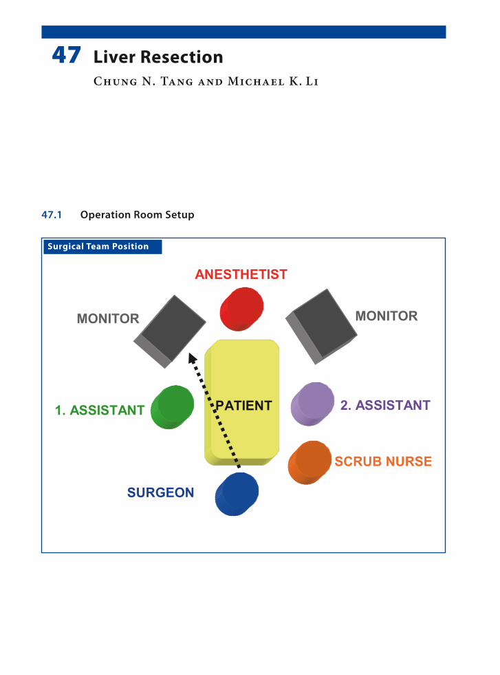
Surgical Team Position
47.1 Operation Room Setup
47 Liver ResectionChung N. Tang and Michael K. Li
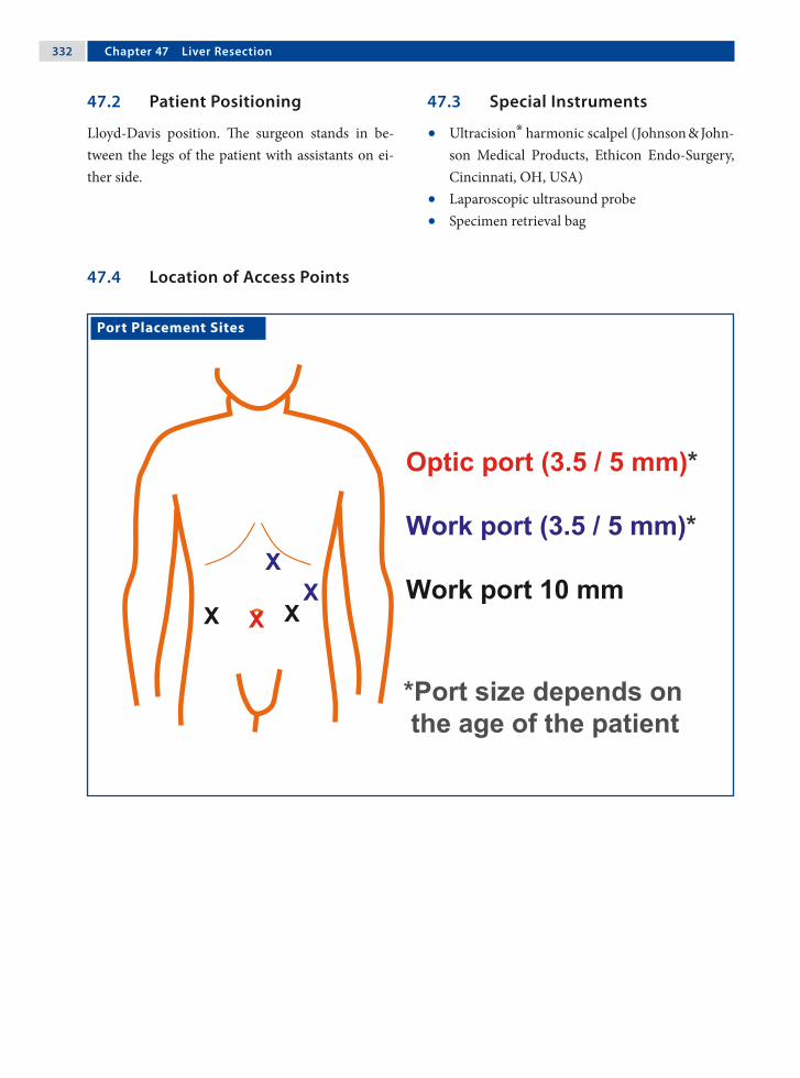
332 Chapter �� Liver Resection
Port Placement Sites
47.3 Special Instruments
• Ultracision® harmonic scalpel (Johnson & John-son Medical Products, Ethicon Endo-Surgery, Cincinnati, OH, USA)
• Laparoscopic ultrasound probe• Specimen retrieval bag
47.2 Patient Positioning
Lloyd-Davis position. The surgeon stands in be-tween the legs of the patient with assistants on ei-ther side.
47.4 Location of Access Points

Chung N. Tang and Michael K. Li 333
47.5 Indications
Benign liver tumor (solitary lesion in the antero-lateral segments of the liver); this procedure is still under investigation for pediatric patients.
47.6 Contraindications
1. Insufficient liver function.2. Severe portal hypertension.3. Cardiorespiratory dysfunction.4. Coagulopathies.5. Previous surgeries (relative contraindication).
47.8 Technical Notes
1. The use of a 30° laparoscope is recommended as it can provide a wider range of view.
2. For a patient with good liver reserves, the Prin-gle maneuver is recommended, which can sig-nificantly decrease operative blood loss.
3. Lowering the central venous pressure to < 5 cmH2O (i.e., < 3.7 mmHg) is an effective means of reducing operative blood loss.
47.7 Preoperative Considerations
1. Ensure there is enough blood available together with fresh frozen plasma and platelets (depend-ing on conditions).
2. Have an intensive care unit bed available for the patient should it be needed postoperatively.
3. Insert a urinary catheter.4. Place a central venous line and/or an arterial
catheter.5. Prophylactic antibiotics are administered and
light bowel preparation is beneficial.
47.9 Procedure Variations
1. Total laparoscopic liver resections.2. Hand-assisted laparoscopic resections.
47.10 Laparoscopic Liver Resection
Please see Figs. 1–8.

33� Chapter �� Liver Resection
Figure 47.1 Figure 47.2
Figure 47.3 Figure 47.4
The liver is mobilized to expose the surface on ei-ther sides of the falciform ligament.
Laparoscopic ultrasonography is used to confirm the number and size of the lesions, and to define their relationship with the intrahepatic vascular structures
The avascular lesser omentum is divided and a vas-cular sling is passed around the hepatoduodenal ligament. If portal control is required, the tension can be tightened and retained by artery forceps
The desired plane of transection is marked on the liver surface with diathermy

Chung N. Tang and Michael K. Li 33�
Figure 47.5 Figure 47.6
Figure 47.7 Figure 47.8
Hepatic transection is performed with a harmonic scalpel
Transection is performed cautiously to circumvent the lesion
Bipolar electrocoagulation or an argon-beam coag-ulator is used for minor bleeding, and larger struc-tures are secured with clips. Portal pedicles and ma-jor hepatic veins are divided by application of an endoscopic stapler
The resected specimen is placed in a specimen re-trieval bag and then extracted

33� Chapter �� Liver Resection
Recommended Literature
1. Dutta S, Nehra D, Woo R, Cohen I (2007) Laparoscopic resection of a benign liver tumor in a child. J Pediatr Surg. 42:1141–1145
2. Tang CN, Tsui KK, Ha JP, Yang GP, Li MK (2006) A single-centre experience of 40 laparoscopic liver re-sections. Hong Kong Med J 12:419–425
3. Yoon YS, Han HS, Choi YS, Lee SI, Jang JY, Suh KS, Kim SW, Lee KU, Park YH (2006) Total laparoscopic left lateral sectionectomy performed in a child with be-nign liver mass. J Pediatr Surg 41:25–28

Surgical Team Position
48.1 Operation Room Setup
48 Management of Hydatid CystsFrancisco J. Berchi

33� Chapter �� Management of Hydatid Cysts
48.3 Special Instruments
• LigaSure™ (Valleylab, Boulder, CO, USA) or Ul-tracision® harmonic scalpel (Johnson & Johnson Medical Products, Ethicon Endo-Surgery, Cin-cinnati, OH, USA)
• Tru-cut needle (Tru-cut®; Allegiance Health-care Corp., McGraw Park, IL, USA)
• Five culture test tubes• Specimen retrieval bag
Port Placement Sites
48.2 Patient Positioning
The patient is positioned “supine” at the end of the operating table with arms tucked to the side. The surgeon stands between the patient’s legs.
48.4 Location of Access Points

Francisco J. Berchi 33�
48.5 Indications
1. Echinococcus cysts (single and multiple).2. Small multivesicular cysts with calcification and
located near the liver surface.
48.6 Contraindications
1. Infected cysts (sepsis).2. Peritonitis.3. Anaphylactic reaction or dissemination of dis-
ease.
48.8 Technical Notes
1. A 14-gauge, conventional, intravenous catheter or a Veress needle is introduced into the abdom-inal cavity for continuous irrigation of the sur-face of the liver and the cyst with 10% saline.
2. A percutaneous transhepatic (never directly in to the cyst) Tru-Cut-type needle or Advocat-cannula that is connected to a suction/irrigation device is inserted into the cyst.
3. Inject 20 ml hypertonic 20% or 10% saline into the cyst and leave it for 5–10 min.
4. Suction is performed at the base of the cyst.
48.7 Preoperative Considerations
1. The medical treatment is albendazole 15 mg/kg/day for 4 weeks with cessation for 2 weeks. This is repeated for three or more cycles: Hepatic function is monitored during the entire course of this therapy.
2. It is important to inform the family about the complications of surgery; particularly that of perioperative intra-abdominal dissemination of hydatids (scolices and anaphylactic reaction).
3. Nasogastric tube, urinary bladder catheter, and broad-spectrum antibiotics.
48.9 Procedure Variations
1. Multivesicular cysts, which are usually small with calcifications and located near the liver surface can be treated by complete laparoscopic resection using electrocautery, ultrasonic cavit-ron device, laser, or LigaSure™.
2. Hemostasis is essential and bile leakage may be stopped by directly suturing; with or without fi-brin glue.
3. An omental patch may be used to obliterate the cavity left by the cyst.
48.10 Laparoscopic Management of Hydatid Cysts
Please see Figs. 1–6.

3�0 Chapter �� Management of Hydatid Cysts
Figure 48.1 Figure 48.2
Veress
Tru Cut®
20% NaCl 10% NaCl
Figure 48.3 Figure 48.4
Axial computed tomography is obtained to assist in the planning of the laparoscopic procedure
Setup overview: a Veress needle is used for continu-ous liver surface irrigation with 10% NaCl. The Tru-Cut® needle is placed in the cyst to allow the ap-plication of 20% NaCl application and aspiration of the cyst contents
Exploration of the entire abdomen is performed. The liver surface is carefully examined to identify the cyst
A percutaneous transhepatic Tru-Cut® needle is in-serted into the cyst and suction and irrigation is carried out a minimum of five times

Francisco J. Berchi 3�1
Recommended Literature
1. Berchi FJ (1981) Tratamiento Endoquirurgico de la Hi-datidosis Heptica en la Infancia. Premio Video-Med, Badajoz/España
2. Chen W, Xusheng L (2007) Laparoscopic surgical tech-niques in patients with hepatic hydatid cyst. Am J Surg 194:243–247
3. Maazoun K, Mekki M, Chioukh F, Sahnoun L, Ksia A, Jouini R, Jallouli M, Krichene I, Belghith M, Nouri A (2007) Laparoscopic treatment of hydatid cyst of the liver in children. A report on 34 cases. J Pediatr Surg 42:1683–1686
Figure 48.5 Figure 48.6
Once the cavity is completely cleared, the cyst is in-cised directly with electrosurgical scissors and the germinal layer is removed
The cyst wall is resected with a harmonic device and retrieved using a specimen retrieval bag. A Jackson-Pratt drain is placed before closure
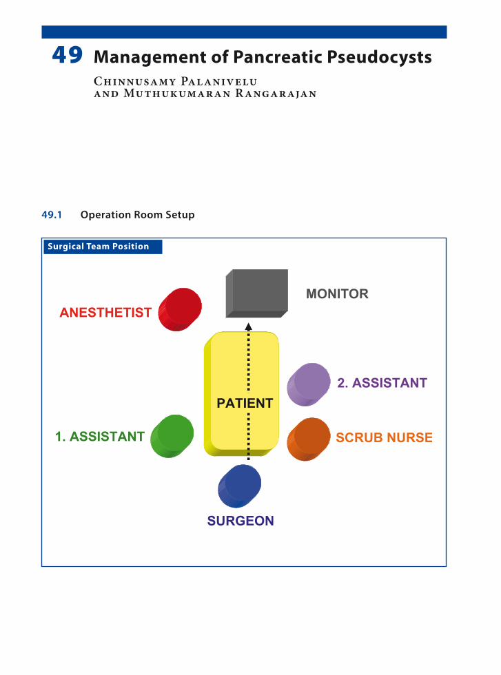
Surgical Team Position
49.1 Operation Room Setup
49 Management of Pancreatic PseudocystsChinnusamy Palanivelu and Muthukumaran Rangarajan
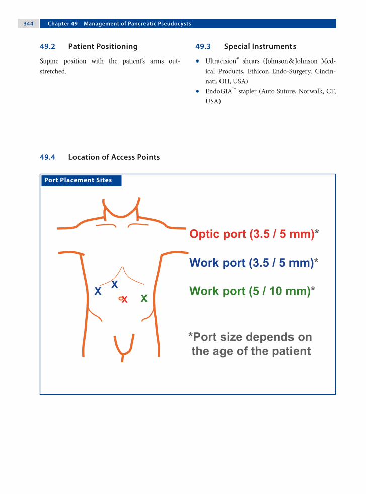
3�� Chapter �� Management of Pancreatic Pseudocysts
Port Placement Sites
49.3 Special Instruments
• Ultracision® shears (Johnson & Johnson Med-ical Products, Ethicon Endo-Surgery, Cincin-nati, OH, USA)
• EndoGIA™ stapler (Auto Suture, Norwalk, CT, USA)
49.2 Patient Positioning
Supine position with the patient’s arms out-stretched.
49.4 Location of Access Points
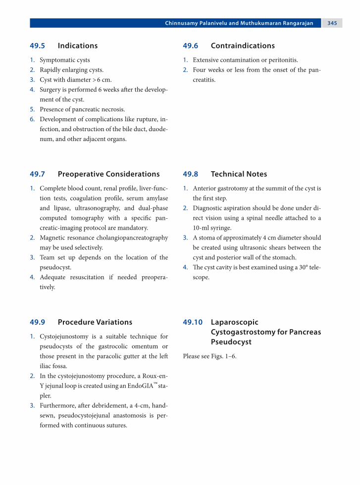
Chinnusamy Palanivelu and Muthukumaran Rangarajan 3��
49.5 Indications
1. Symptomatic cysts2. Rapidly enlarging cysts.3. Cyst with diameter > 6 cm.4. Surgery is performed 6 weeks after the develop-
ment of the cyst.5. Presence of pancreatic necrosis.6. Development of complications like rupture, in-
fection, and obstruction of the bile duct, duode-num, and other adjacent organs.
49.6 Contraindications
1. Extensive contamination or peritonitis.2. Four weeks or less from the onset of the pan-
creatitis.
49.8 Technical Notes
1. Anterior gastrotomy at the summit of the cyst is the first step.
2. Diagnostic aspiration should be done under di-rect vision using a spinal needle attached to a 10-ml syringe.
3. A stoma of approximately 4 cm diameter should be created using ultrasonic shears between the cyst and posterior wall of the stomach.
4. The cyst cavity is best examined using a 30° tele-scope.
49.7 Preoperative Considerations
1. Complete blood count, renal profile, liver-func-tion tests, coagulation profile, serum amylase and lipase, ultrasonography, and dual-phase computed tomography with a specific pan-creatic-imaging protocol are mandatory.
2. Magnetic resonance cholangiopancreatography may be used selectively.
3. Team set up depends on the location of the pseudocyst.
4. Adequate resuscitation if needed preopera-tively.
49.9 Procedure Variations
1. Cystojejunostomy is a suitable technique for pseudocysts of the gastrocolic omentum or those present in the paracolic gutter at the left iliac fossa.
2. In the cystojejunostomy procedure, a Roux-en-Y jejunal loop is created using an EndoGIA™ sta-pler.
3. Furthermore, after debridement, a 4-cm, hand-sewn, pseudocystojejunal anastomosis is per-formed with continuous sutures.
49.10 Laparoscopic Cystogastrostomy for Pancreas Pseudocyst
Please see Figs. 1–6.

3�� Chapter �� Management of Pancreatic Pseudocysts
Figure 49.1 Figure 49.2
Figure 49.3 Figure 49.4
An anterior gastrotomy is performed with Ultra-cision® shears. The pseudocyst can be seen bulging through the posterior wall of the stomach
Diagnostic percutaneous aspiration of fluid from the cyst is performed
A summit stitch is placed on the posterior wall of the stomach
A cystostomy is performed through the posterior gastric wall using Ultracision® shears

Chinnusamy Palanivelu and Muthukumaran Rangarajan 3��
Recommended Literature
1. Bufo AJ (2004) Endolaparoscopic cystogastrostomy: pushing the envelope of minimally invasive surgery in children. Pediatr Endosurg Inn Tech 8:344–347
2. Saad DF, Gow KW, Cabbabe S, Heiss KF, Wulkan ML (2005) Laparoscopic cystogastrostomy for the treat-ment of pancreatic pseudocysts in children. J Pediatr Surg 40:e13–17
3. Seitz G, Warmann SW, Kirschner HJ, Haber HP, Schae-fer JW, Fuchs J (2006) Laparoscopic cystojejunostomy as a treatment option for pancreatic pseudocysts in children – a case report. J Pediatr Surg 41:e33–35
Figure 49.5 Figure 49.6
A necrosectomy is performed and the debris at-tached to the wall of the cyst is removed
The anterior gastrotomy is closed with continuous intracorporeal sutures

Surgical Team Position
50.1 Operation Room Setup
50 PancreatectomyMark L. Wulkan

3�0 Chapter �0 Pancreatectomy
50.3 Special Instruments
• Ultracision® shears (Johnson & Johnson Med-ical Products, Ethicon Endo-Surgery, Cincin-nati, OH, USA)
• LigaSure™ (Valleylab, Boulder, CO, USA).• Specimen retrieval bag
Port Placement Sites
50.2 Patient Positioning
Young patients are placed in the frog-leg position. Older patients are placed in the lithotomy position. The surgeon stands in the “French” position, be-tween the patient’s legs or at the foot of the bed.
50.4 Location of Access Points

Mark L. Wulkan 3�1
50.5 Indications
1. Insulinoma.2. Hyperinsulinism.3. Trauma.4. Other pancreatic tumors.
50.6 Contraindications
General contraindications to laparoscopic surgery.
50.8 Technical Notes
1. Suspend the stomach from the abdominal wall with a heavy suture.
2. Ultrasonic shears and the LigaSure™ bipolar de-vice are effective at dividing the parenchyma.
3. Cholangiography may be necessary to identify the location of the common bile duct.
50.7 Preoperative Considerations
1. Glucose levels should be controlled.2. Preoperative work-up for hyperinsulinism may
include magnetic resonance imaging, computed tomography, selective venous sampling, or a se-lective calcium stimulation test.
3. New nuclear medicine scans are being developed to help localize insulinoma.
50.9 Procedure Variations
1. With the patient positioned on the right lateral side, the plane located between the left kidney and the posterior aspects of the spleen and pan-creas can be dissected.
2. Application of tissue sealant to prevent fistula formation after pancreatectomy.
3. The Penrose drain “lasso” technique can be em-ployed for atraumatic manipulation of the pan-creas during the procedure.
50.10 Laparoscopic Pancreatectomy
Please see Figs. 1–9.
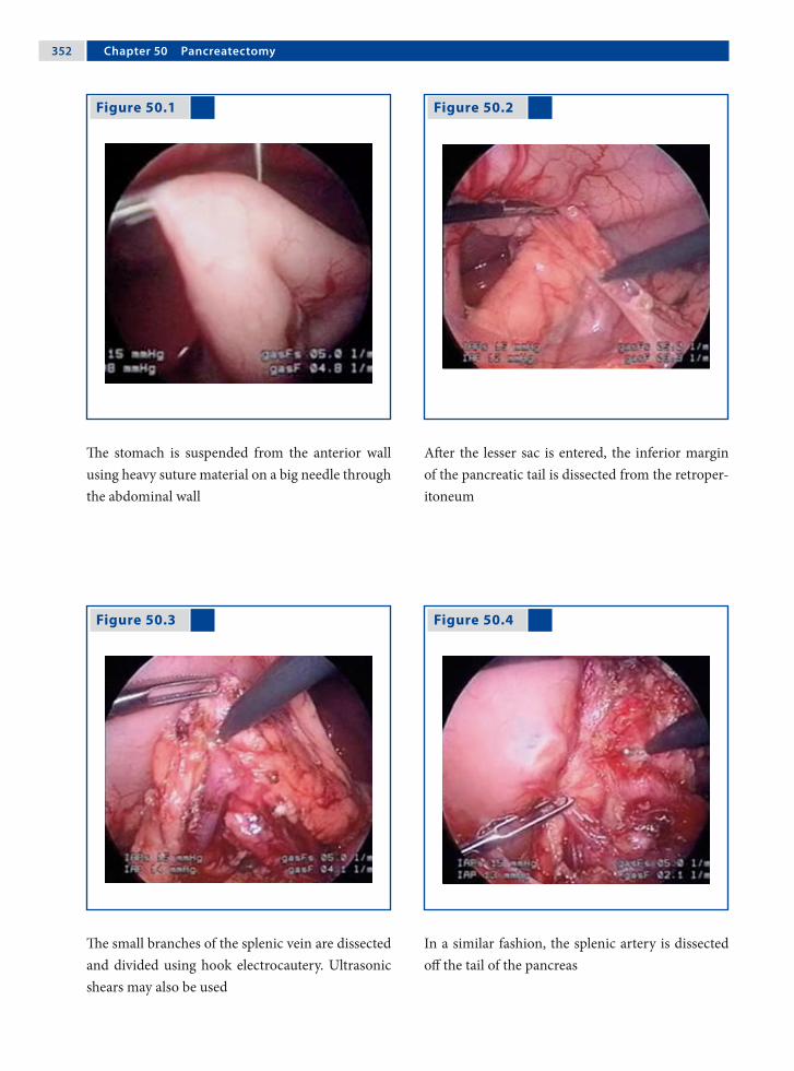
3�2 Chapter �0 Pancreatectomy
Figure 50.1 Figure 50.2
Figure 50.3 Figure 50.4
The stomach is suspended from the anterior wall using heavy suture material on a big needle through the abdominal wall
After the lesser sac is entered, the inferior margin of the pancreatic tail is dissected from the retroper-itoneum
The small branches of the splenic vein are dissected and divided using hook electrocautery. Ultrasonic shears may also be used
In a similar fashion, the splenic artery is dissected off the tail of the pancreas

Mark L. Wulkan 3�3
Figure 50.5 Figure 50.6
Figure 50.7 Figure 50.8
The tail is free and the uncinate process can be seen next to the confluence of the splenic and su-perior mesenteric arteries. The uncinate process is dissected off the superior mesenteric artery using hook electrocautery
The transverse pancreatic arteries are controlled us-ing the LigaSure™
device as the gland is divided
The divided pancreas is placed in a specimen re-trieval bag for removal
The pancreatic stump is over sewn
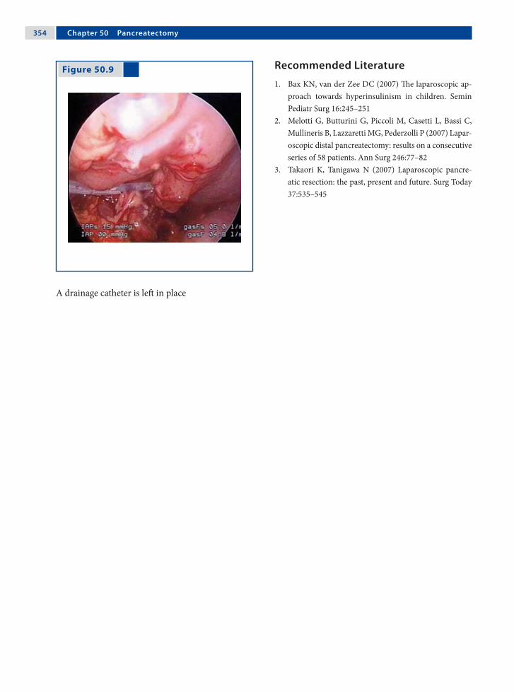
3�� Chapter �0 Pancreatectomy
Figure 50.9 Recommended Literature
1. Bax KN, van der Zee DC (2007) The laparoscopic ap-proach towards hyperinsulinism in children. Semin Pediatr Surg 16:245–251
2. Melotti G, Butturini G, Piccoli M, Casetti L, Bassi C, Mullineris B, Lazzaretti MG, Pederzolli P (2007) Lapar-oscopic distal pancreatectomy: results on a consecutive series of 58 patients. Ann Surg 246:77–82
3. Takaori K, Tanigawa N (2007) Laparoscopic pancre-atic resection: the past, present and future. Surg Today 37:535–545
A drainage catheter is left in place

Surgical Team Position
51.1 Operation Room Setup
51 Splenectomy and Related ProceduresPaul Philippe

3�� Chapter �1 Splenectomy and Related Procedures
51.3 Special Instruments
• EnSeal® (SurgRx, Redwood City, CA, USA) Tis-sue Sealing Device (TSD) or
• Ultracision® harmonic scalpel (Johnson & John-son Medical Products, Ethicon Endo-Surgery, Cincinnati, OH, USA) or
• 5-mm clip applicator• Tachosil® (Nycomed GmbH, Zürich, Switzer-
land)
Port Placement Sites
51.2 Patient Positioning
Right lateral decubitus with a roll under the right flank. If associated with cholecystectomy, a 45° lat-eral decubitus position is preferred (the table is tilted to the side for the splenic part and returned to neutral position for the biliary part of the pro-cedure).
51.4 Location of Access Points

Paul Philippe 3��
51.5.2 Contraindications
1. Hemodynamic instability (trauma).2. Splenic abscesses.3. Massive splenomegaly requires advanced skills
and experience. Consider preoperative emboli-zation.
51.5.4 Technical Notes
1. Insert trocars under visual guidance to avoid splenic injury in cases of splenomegaly.
2. The artery and vein should be dissected and oc-cluded separately.
3. Keep the spleen attached to the left upper quad-rant and use gravity to retract the stomach and colon.
4. A large, spring-loaded specimen-retrieval bag allows the surgeon to “scoop” the spleen from its lower pole upward.
5. Retrieve the bag through an enlarged umbili-cal incision. Use fingers or atraumatic forceps to morcelate the spleen, since rupture of the speci-men-retrieval bag carries the risk of splenosis.
51.5.3 Preoperative Considerations
1. Consider pneumococcal vaccination and peri-operative penicillin administration.
2. Consider partial splenectomy in hemolytic dis-orders. The extent of resection depends on the severity of hemolysis (resect the larger part of the spleen if hemolysis is severe).
3. Type- and cross-matching is prudent in par-tial splenectomies. Platelet transfusion may be necessary.
51.5.5 Procedure Variations
1. Dorsal decubitus positioning of the patients can be done; however, this requires more ports for exposure.
2. Vascular control can be achieved safely with intracorporeal ligatures, but it is faster with a TSD.
3. The specimen can be extracted through a Pfan-nenstiel incision in the case of massive spleno-megaly or if an intact specimen is required for pathological evaluation.
51.5 Total Splenectomy
51.5.1 Indications
1. Hematologic disorders including hereditary spherocytosis.
2. Immune thrombocytopenic purpura.3. Sickle cell anemia.4. Tumors.
51.5.6 Laparoscopic Total Splenectomy
Please see Figs. 1–8.

3�� Chapter �1 Splenectomy and Related Procedures
Figure 51.1 Figure 51.2
Figure 51.3 Figure 51.4
With the spleen lifted by the flank instrument, the colosplenic ligaments are taken down
The gastrosplenic ligament (short gastric vessels) is opened with the LigaSure™
tissue-sealing device
The dissection of the splenic hilus is performed with the intention of isolating the splenic artery from the vein
The artery can be ligated and divided using a vari-ety of techniques. The most preferred devices for li-gation are clips, hand ligatures, or tissue-sealing de-vices

Paul Philippe 3��
Figure 51.5 Figure 51.6
The vein is ligated and divided similarly. A tissue-sealing device as shown here is preferred for this purpose
The posterior attachments are taken down, keeping the spleen “hung” to facilitate specimen retrieval bag insertion
Figure 51.7 Figure 51.8
The spleen is “scooped” into a large specimen re-trieval bag, with the lower pole being introduced into the bag first
The specimen is fragmented in the bag using a fin-ger or an atraumatic forceps, and then extracted
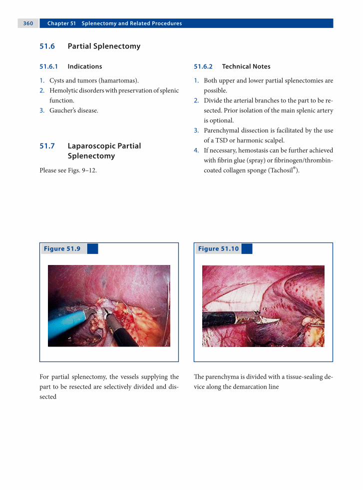
3�0 Chapter �1 Splenectomy and Related Procedures
51.7 Laparoscopic Partial Splenectomy
Please see Figs. 9–12.
Figure 51.9 Figure 51.10
For partial splenectomy, the vessels supplying the part to be resected are selectively divided and dis-sected
The parenchyma is divided with a tissue-sealing de-vice along the demarcation line
51.6 Partial Splenectomy
51.6.1 Indications
1. Cysts and tumors (hamartomas).2. Hemolytic disorders with preservation of splenic
function.3. Gaucher’s disease.
51.6.2 Technical Notes
1. Both upper and lower partial splenectomies are possible.
2. Divide the arterial branches to the part to be re-sected. Prior isolation of the main splenic artery is optional.
3. Parenchymal dissection is facilitated by the use of a TSD or harmonic scalpel.
4. If necessary, hemostasis can be further achieved with fibrin glue (spray) or fibrinogen/thrombin-coated collagen sponge (Tachosil®).
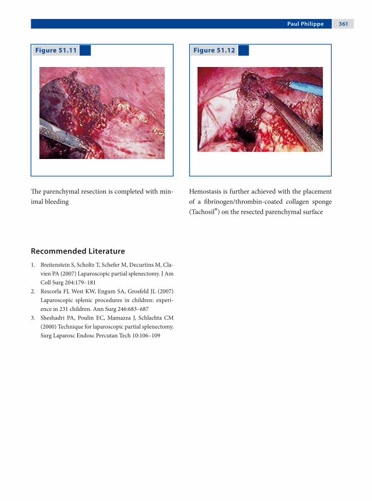
Paul Philippe 3�1
Figure 51.11 Figure 51.12
The parenchymal resection is completed with min-imal bleeding
Hemostasis is further achieved with the placement of a fibrinogen/thrombin-coated collagen sponge (Tachosil®) on the resected parenchymal surface
Recommended Literature
1. Breitenstein S, Scholtz T, Schefer M, Decurtins M, Cla-vien PA (2007) Laparoscopic partial splenectomy. J Am Coll Surg 204:179–181
2. Rescorla FJ, West KW, Engum SA, Grosfeld JL (2007) Laparoscopic splenic procedures in children: experi-ence in 231 children. Ann Surg 246:683–687
3. Sheshadri PA, Poulin EC, Mamazza J, Schlachta CM (2000) Technique for laparoscopic partial splenectomy. Surg Laparosc Endosc Percutan Tech 10:106–109

Surgical Team Position
52.1 Operation Room Setup
52 Mesh Splenopexy for Wandering SpleenChinnusamy Palanivelu and Muthukumaran Rangarajan

3�� Chapter �2 Mesh Splenopexy for Wandering Spleen
Port Placement Sites
52.3 Special Instruments
Polypropylene composite mesh.
52.2 Patient Positioning
Right lateral decubitus position with a roll placed under the right flank.
52.4 Location of Access Points

Chinnusamy Palanivelu and Muthukumaran Rangarajan 3��
52.5 Indications
1. Wandering spleen.2. Pelvic spleen.3. Torsion of the spleen.4. Large splenic cysts that require laparoscopic
mobilization of the spleen and its reattachment in the left upper quadrant.
52.6 Contraindications
Asymptomatic splenic infarct requires no surgical intervention.
52.8 Technical Notes
1. The spleen is generally found attached to an ab-normally long tortuous vascular pedicle with no gastrosplenic or phrenicosplenic ligaments.
2. The posterior peritoneum over the left kidney is opened and a flap that includes the peritoneum over the anterior abdominal wall is lifted up to create a raw area.
3. A composite polypropylene mesh of 15 × 15 cm is sutured over the raw area with 3–0 nonabsorb-able sutures and wrapped around the spleen.
52.7 Preoperative Considerations
1. Ultrasonography and color Doppler study should confirm the diagnosis by revealing the exact location and the status of the spleen.
2. Vaccination (pneumococcal, Haemophilus in-fluenzae, meningococcal) is mandatory.
3. The patient or the parents must be informed about the possibility of complete splenectomy if the viability of the spleen is found to be ques-tionable during surgery.
52.9 Procedure Variations
1. Splenectomy is an option if vascular compro-mise is present.
2. Splenopexy without mesh is possible by creat-ing an extraperitoneal pouch.
3. Splenopexy with double mesh (“sandwich tech-niques”) is another alternative.
52.10 Laparoscopic Mesh Splenopexy for Wandering Spleen
Please see Figs. 1–6.

3�� Chapter �2 Mesh Splenopexy for Wandering Spleen
Figure 52.1 Figure 52.2
Figure 52.3 Figure 52.4
The wandering spleen is localized in the left iliac fossa
The spleen is positioned in the left hypochondrium. Torsion of the vascular pedicle is observed without evidence of vascular compromise to the spleen
A raw area is created by raising the peritoneal flap around the area foreseen for the positioning of the spleen
A 15 × 15-cm composite mesh is introduced in the abdomen and sutured over the raw peritoneal area

Chinnusamy Palanivelu and Muthukumaran Rangarajan 3��
Recommended Literature
1. Fukuzawa H, Urushihara N, Ogura K, Miyazaki E, Matsuoka T, Fukumoto K Kimura S, Mitsunaga M, Hasegawa S (2006) Laparoscopic splenopexy for wan-dering spleen: extraperitoneal pocket splenopexy. Pe-diatr Surg Int 22:931–934
2. Hedeshian MH, Hirsh MP, Danielson PD (2005) Lapar-oscopic splenopexy of a pediatric wandering spleen by creation of a retroperitoneal pocket. J Laparoendosc Adv Surg Tech A 15:670–672
3. Nomura H, Haji S, Kuroda D, Yasuda K, Ohyanagi H, Kudo M (2000) Laparoscopic splenopexy for adult wandering spleen: Sandwich method with two sheets of absorbable knitted mesh. Surg Laparosc Endosc Per-cutan Tech 10:332–334
Figure 52.5 Figure 52.6
The mesh is wrapped around the spleen to secure it from both the sides. The edges of the mesh meet in the area around the vascular pedicle and are su-tured
The spleen is “wrapped” between the two flanks of the mesh, along with reinforcement using omen-tum

Section 5 Genitourinary Procedures

Surgical Team Position
53.1 Operation Room Setup
53 Inguinal Hernia RepairFrançois Becmeur

3�2 Chapter �3 Inguinal Hernia Repair
53.3 Special Instruments
• Atraumatic forceps• Needle holders
Port Placement Sites
53.2 Patient Positioning
Supine position with arms tucked to side. Staff po-sition for right hernia repair is shown (for the left side the surgeon and assistant switch places).
53.4 Location of Access Points

François Becmeur 3�3
53.5 Indications
1. Patent processus vaginalis.2. Inguinal hernia (in both sexes).3. Incarcerated hernia.4. Femoral hernia.5. Direct hernia.6. Recurrence of groin hernias.
53.6 Contraindications
1. Premature infants (relative contraindication).2. Contraindications to general anesthesia.
53.8 Technical Notes
1. Identify the type of hernia and evaluate the con-tralateral side.
2. Open the peritoneal fold at the outer circumfer-ence of the internal inguinal ring.
3. Hernia sac dissection is aided by insufflation. The sac must be divided and a peritoneal ring around the sac must be removed.
4. Ensure that there is no residual processus vagi-nalis. Nonabsorbable 3–0 sutures are used.
53.7 Preoperative Considerations
1. Similar to day-care preparation procedures.2. Empty the urinary bladder before the proce-
dure.3. A Foley catheter is not necessary for the proce-
dure.
53.9 Procedure Variations
1. Laparoscopic inversion and ligation of ingui-nal hernia in girls. In this procedure the sac is grasped, inverted, and then ligated with an en-doloop using 3-mm instruments without ports.
2. Subcutaneous endoscopically assisted ligation (SEAL): A stab incision is made on the skin above the internal inguinal ring and under en-doscopic visualization the internal inguinal ring is encircled passing a nonabsorbable suture on a large needle (T12 or T20).
53.10 Laparoscopic Inguinal Hernia Repair
Please see Figs. 1–4.

3�� Chapter �3 Inguinal Hernia Repair
Figure 53.1 Figure 53.2
Figure 53.3 Figure 53.4
Laparoscopic view of a patent process vaginalis on the right side
The edge of the inguinal sac is held with a grasper and the peritoneum is opened
After circular preparation the peritoneum is di-vided from the inguinal sac
The suture needle is introduced through the ab-dominal wall and the sac sutured

François Becmeur 3��
Recommended Literature
1. Becmeur F, Philippe P, Lemandat-Schultz A, Moog R, Grandadam S, Lieber A, Toledano D (2004) A continu-ous series of 96 laparoscopic inguinal hernia repairs in children by a new technique. Surg Endosc 18:1738–1741
2. Montupet P, Esposito C (1999) Laparoscopic treat-ment of congenital inguinal hernia in children. J Pedi-atr Surg 34:420–423
3. Schier F, Klizaite J (2004) Rare inguinal hernias forms in children. Pediatr Surg Int 20:748–752
Figure 53.5 Figure 53.6
Example of right femoral hernia with a patent pro-cess vaginalis
Example of incarceration of the greater omentum in the left inguinal ring

Surgical Team Position
54.1 Operation Room Setup
54 Procedure Options in Undescended TestisOliver J. Muensterer and Holger Till

3�� Chapter �� Procedure Options in Undescended Testis
54.3 Special Instruments
• Ultracision® shears (Johnson & Johnson Med-ical Products, Ethicon Endo-Surgery, Cincin-nati, OH, USA) or
• Endoscopic clip applicator
Port Placement Sites
54.2 Patient Positioning
Supine position with arms tucked to the side. The ipsilateral side may be abducted if required. Staff position for right-side exploration is shown here.
54.4 Location of Access Points

Oliver J. Muensterer and Holger Till 3��
54.5 Indications
1. Nonpalpable unilateral testis.2. Nonpalpable bilateral testis with male karyo-
type and positive human chorionic gonadotro-phin (hCG) test.
54.6 Contraindications
Patients with nonpalpable bilateral testis and nega-tive hCG test require a preoperative pediatric endo-crine work-up.
54.8 Technical Notes
1. Place the umbilical port and perform a diag-nostic laparoscopy to identify the position and morphology of the affected testis, vas, and ves-sels.
2. In order to mobilize the testicle, the gubernacu-lum is transected.
3. Grasp the testis only by the remaining guber-nacular attachments to avoid tissue trauma.
4. Deflating the pneumoperitoneum may add length to the spermatic cord for orchidopexy.
54.7 Preoperative Considerations
1. Imaging studies cannot reliably rule out intra-abdominal testes.
2. Place a Foley catheter before the procedure to drain the bladder and maximize the operating space in the lower pelvis.
3. The Trendelenburg position aids in better visu-alization of the lower abdomen and pelvis.
4. The operating table should be tilted ipsilateral side up.
54.9 Procedure Variations
1. Finding a testis with normal vessels and a blind-ending or absent vas may indicate cystic fibro-sis. If possible, an orchidopexy should be per-formed in these patients.
2. In case of dysplastic or malformed testes, orchi-ectomy or biopsy should be performed.
54.10 Laparoscopic Approach to Undescended Testis
Please see Figs. 1–6.

3�0 Chapter �� Procedure Options in Undescended Testis
Figure 54.1 Figure 54.2
If both the vas deferens and vessels enter the ingui-nal canal, laparoscopy is terminated and open stan-dard inguinal exploration is performed
If the vas and vessels lead to a normal intra-ab-dominal testis, determine if the testis is low (< 3 cm from the inguinal ring or below the iliac vessels) or high. Low testes are treated by conventional or lap-aroscopic orchidopexy

Oliver J. Muensterer and Holger Till 3�1
Figure 54.3 Figure 54.4
High-lying intra-abdominal testes may require a two-stage Fowler-Stephens procedure
The first stage comprises transection of the testic-ular vessels and placing the testicle near the inter-nal inguinal ring. After a 6-month interval, orchi-dopexy is performed (at this time a strip of the peri-toneum around the testicle is preserved and mobi-lized along with the testis)
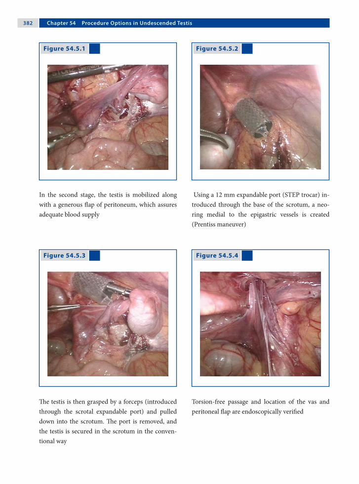
3�2 Chapter �� Procedure Options in Undescended Testis
Figure 54.5.1 Figure 54.5.2
Figure 54.5.3 Figure 54.5.4
In the second stage, the testis is mobilized along with a generous flap of peritoneum, which assures adequate blood supply
Using a 12 mm expandable port (STEP trocar) in-troduced through the base of the scrotum, a neo-ring medial to the epigastric vessels is created (Prentiss maneuver)
The testis is then grasped by a forceps (introduced through the scrotal expandable port) and pulled down into the scrotum. The port is removed, and the testis is secured in the scrotum in the conven-tional way
Torsion-free passage and location of the vas and peritoneal flap are endoscopically verified

Oliver J. Muensterer and Holger Till 3�3
Recommended Literature
1. Patil KK, Green JS, Duffy PG (2005) Laparoscopy for impalpable testes. BJU Int 95:704–708
2. Peters CA (2004) Laparoscopy in pediatric urology. Curr Opin Urol 14:67–73
3. Schleef J, von Bismark S, Burmucic K, Gutmann A, Mayr J (2002) Groin exploration for nonpalpable tes-tes: laparoscopic approach. J Pediatr Surg 37:1552–1555
Figure 54.6
If the vas and vessels end blindly before the ingui-nal ring and no testes are identified despite a thor-ough search (intrauterine torsion, atrophy, or apla-sia), the operation is terminated (Courtesy of Prof Jürgen Waldschmidt)

Surgical Team Position
55.1 Operation Room Setup
55 First Step Fowler-Stephens in Prune-Belly SyndromeAmulya K. Saxena
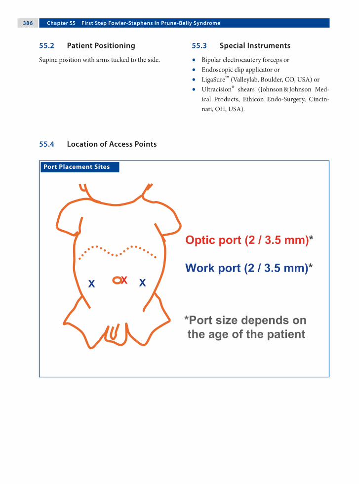
3�� Chapter �� First Step Fowler-Stephens in Prune-Belly Syndrome
Port Placement Sites
55.3 Special Instruments
• Bipolar electrocautery forceps or• Endoscopic clip applicator or• LigaSure™ (Valleylab, Boulder, CO, USA) or• Ultracision® shears (Johnson & Johnson Med-
ical Products, Ethicon Endo-Surgery, Cincin-nati, OH, USA).
55.2 Patient Positioning
Supine position with arms tucked to the side.
55.4 Location of Access Points
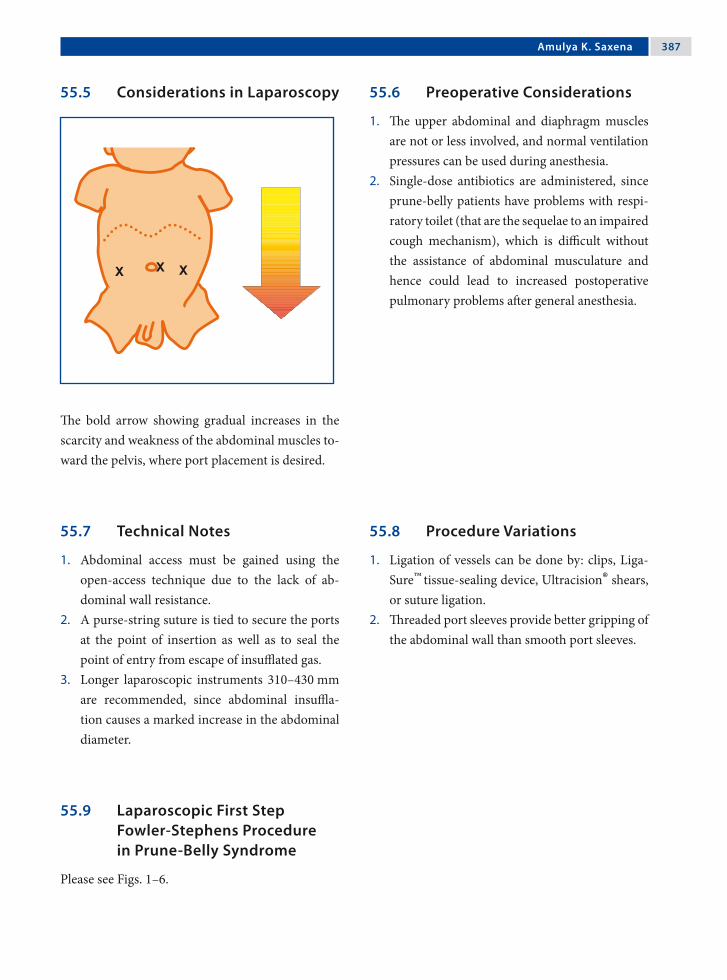
Amulya K. Saxena 3��
55.5 Considerations in Laparoscopy
The bold arrow showing gradual increases in the scarcity and weakness of the abdominal muscles to-ward the pelvis, where port placement is desired.
55.6 Preoperative Considerations
1. The upper abdominal and diaphragm muscles are not or less involved, and normal ventilation pressures can be used during anesthesia.
2. Single-dose antibiotics are administered, since prune-belly patients have problems with respi-ratory toilet (that are the sequelae to an impaired cough mechanism), which is difficult without the assistance of abdominal musculature and hence could lead to increased postoperative pulmonary problems after general anesthesia.
55.7 Technical Notes
1. Abdominal access must be gained using the open-access technique due to the lack of ab-dominal wall resistance.
2. A purse-string suture is tied to secure the ports at the point of insertion as well as to seal the point of entry from escape of insufflated gas.
3. Longer laparoscopic instruments 310–430 mm are recommended, since abdominal insuffla-tion causes a marked increase in the abdominal diameter.
55.8 Procedure Variations
1. Ligation of vessels can be done by: clips, Liga-Sure™ tissue-sealing device, Ultracision® shears, or suture ligation.
2. Threaded port sleeves provide better gripping of the abdominal wall than smooth port sleeves.
55.9 Laparoscopic First Step Fowler-Stephens Procedure in Prune-Belly Syndrome
Please see Figs. 1–6.

3�� Chapter �� First Step Fowler-Stephens in Prune-Belly Syndrome
Figure 55.1 Figure 55.2
Figure 55.3 Figure 55.4
The lax abdomen of a patient with prune-belly syn-drome can pose challenges in endoscopic surgery with regard to insufflation and port placement
Trocars cross the midline with conventional inser-tion methods due to lack of abdominal resistance and hence open insertion is the preferred option
The weak internal spermatic vessels are visualized cranial to the high-lying abdominal testis
Using bipolar electrocautery forceps, the vessels are cauterized and care is taken not to cause thermal injury to the testicle

Amulya K. Saxena 3��
Recommended Literature
1. Docimo SG, Moore R, Kavoussi L (1995) Laparoscopic orchidopexy in the prune belly syndrome: a case re-port and review of the literature. Urology 45:679–681
2. Saxena AK, Brinkmann OA (2007) Unique features of prune belly syndrome in laparoscopic surgery. J Am Coll Surg 205:217–221
3. Yu TJ, Lai MK, Chen WF, Wan YL (1995) Two-stage orchiopexy with laparoscopic clip ligation of the sper-matic vessels in prune-belly syndrome. J Pediatr Surg 30:870–872
Figure 55.5 Figure 55.6
The vessels are divided using scissors, and the tes-tis is lodged close to the inguinal ring. The collat-eral vas deferens vessels maintain the testicular vas-cular supply
The second step of the Fowler-Stephens procedure is performed after 6 months; the strip of perito-neum (dotted lines) overlying the vas and testis is preserved and mobilized with the testis

Surgical Team Position
56.1 Operation Room Setup
56 Management of Ovarian CystsLutz Stroedter

3�2 Chapter �� Management of Ovarian Cysts
56.3 Special Instruments
None.
Port Placement Sites
56.2 Patient Positioning
Supine Trendelenburg position with arms tucked to the side. Operation room position shown for a right-side cyst. The team switches for the left side.
56.4 Location of Access Points

Lutz Stroedter 3�3
56.5 Indications
1. Ovarian cysts (larger than 5 cm in diameter) as-sociated with abdominal pain.
2. Ovarian-cyst-associated torsion.3. Suspected ovarian abscess.
56.6 Relative Contraindications
1. Multiple previous upper abdominal proce-dures.
2. Suspicion of ovarian malignancy.3. General contraindications to laparoscopy.
56.8 Technical Notes
1. Puncture the ovarian cyst with a transcutane-ous laparoscopically guided needle and send the contents for examination.
2. In cases of torsion, wait for 10 min after reliev-ing the torsion to access ovarian vascular recir-culation.
3. During oophoropexy, caution should be taken not to injure the ureter and the vessels close to the site of suture.
56.7 Preoperative Considerations
1. Ovarian enlargement secondary to impaired ve-nous and lymphatic drainage is the most com-mon sonographic finding in ovarian torsion.
2. Combination of Doppler flow imaging with the morphologic assessment of the ovary may im-prove diagnostic accuracy. However, the inter-pretation of Doppler sonography is inconsistent due to the dual ovarian blood supply from the uterine artery and the ovarian artery.
56.9 Procedure Variations
1. Laparoscopically assisted extracorporeal ovar-ian cystectomy.
2. Laparoscopically assisted transumbilical ovar-ian cystectomy in neonates.
56.10 Laparoscopic Approach to Ovarian Cysts
Please see Figs. 1–6.

3�� Chapter �� Management of Ovarian Cysts
Figure 56.1 Figure 56.2
Figure 56.3 Figure 56.4
Laparoscopic view of a hemorrhagic right ovarian cyst leading to ovarian torsion
The ovary is twisted appropriately to reduce the tor-sion. An area for cyst decompression is marked us-ing electrocautery scissors
The cap of the hemorrhagic cyst is then dissected to release the accumulated blood
Using two nonabsorbable sutures the affected ovary is sutured to the pelvic peritoneum

Lutz Stroedter 3��
Recommended Literature
1. Oelsner G, Cohen SB, Soriano D, Admon D, Mashiach S, Carp H (2003) Minimal surgery for the twisted isch-aemic adnexa can preserve ovarian function. Hum Re-prod 18:2599–2602
2. Steyaert H, Meynol F, Valla JS (1998) Torsion of the ad-nexa in children: the value of laparoscopy. Pediatr Surg Int 13:384–387
3. White M, Stella J (2005) Ovarian torsion: 10-year per-spective. Emerg Med Australas 17:231–237
Figure 56.5 Figure 56.6
Postoperative view of the right ovary on completion of the procedure
A contralateral oophoropexy of the normal unaf-fected ovary is performed only in cases of ovarian torsion with severe ischemia and necrosis

Surgical Team Position
57.1 Operation Room Setup
57 AdrenalectomySteven Z. Rubin and Marcos Bettolli

3�� Chapter �� Adrenalectomy
57.3 Special Instruments
• Liver retractor• Specimen retrieval bag• LigaSure™ (Valleylab, Boulder, CO, USA) or • Ultracision® harmonic scalpel (Johnson & John-
son Medical Products, Ethicon Endo-Surgery, Cincinnati, OH, USA)
Port Placement Sites
57.2 Patient Positioning
Right lateral decubitus for left adrenalectomy (shown). Mirror image for staff positions in right adrenalectomy.
57.4 Location of Access Points

Steven Z. Rubin and Marcos Bettolli 3��
57.5 Indications
1. Tumor biopsy.2. Adrenal tumors up to 6 cm.3. Resection of adrenal metastasis.4. Nonfunctioning adrenal incidentaloma > 4 cm.
57.6 Contraindications
1. Large (> 6cm) or irresectable mass-laparoscopic biopsies only.
2. Mass not localized to adrenal-laparoscopic bi-opsies only
3. Preoperatively diagnosed adrenal cancer.4. Noncorrectable coagulopathy.
57.8 Technical Notes
1. Avoid grasping the adrenal gland, especially for pheochromocytoma.
2. LigaSure™/Ultracision® harmonic scalpel is uti-lized for dissection and hemostasis.
3. Initial isolation and division of adrenal vessels is ideal (left adrenal vein; right adrenal vessels are multiple and short).
4. The specimen is extracted in a specimen-re-trieval bag.
5. In the face of uncontrolled complications, con-version to an open procedure is recommended.
57.7 Preoperative Considerations
1. Ensure accurate anatomical delineation and ra-diological staging.
2. Endocrinological management (e.g., pheochro-mocytoma) is essential.
3. Foley catheter and naso-(oro-)gastric tube are inserted.
4. Bilateral antisepsis of the skin of the abdomen and lower chest is required.
57.9 Procedure Variations
1. Retroperitoneal approach.2. Bilateral adrenalectomy.
57.10 Laparoscopic Transabdominal Adrenalectomy
Please see Figs. 1–6.

�00 Chapter �� Adrenalectomy
Figure 57.1 Figure 57.2
Figure 57.3 Figure 57.4
Left-side adrenalectomy; the dissection is started by mobilizing the splenic flexure of the colon
The lienophrenic ligament is divided and Gerota’s fascia is opened
The left renal vein is dissected allowing exposure of the left adrenal vein
The left adrenal vein is ligated with clips and divided

Steven Z. Rubin and Marcos Bettolli �01
Recommended Literature
1. Assalia A, Gagner M (2004) Laparoscopic adrenalec-tomy. Br J Surg 91:1259–1274
2. Lal G, Clark OH (2003) Laparoscopic adrenalectomy – indications and technique. Surg Oncol 12:105–123
3. Miller KA, Albanese C, Harrison M, Farmer D, Ostlie DJ, Gittes G, Holcomb GW 3rd (2002) Experience with lap-aroscopic adrenalectomy in pediatric patients. J Pediatr Surg 37:979–982
Figure 57.5 Figure 57.6
The gland is freed of its attachments using LigaSure™-aided dissection
The isolated gland is placed in a specimen retrieval bag and extracted through the 10-mm port
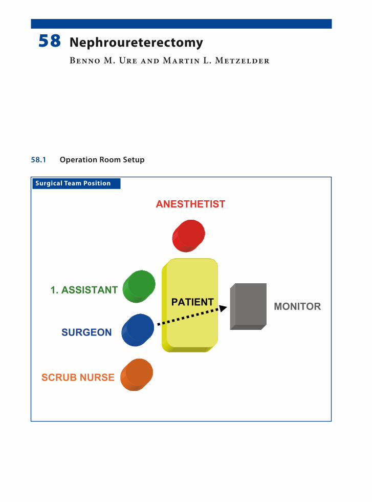
Surgical Team Position
58.1 Operation Room Setup
58 NephroureterectomyBenno M. Ure and Martin L. Metzelder

�0� Chapter �� Nephroureterectomy
58.3 Special Instruments
• 5-mm LigaSure™ (Valleylab, Boulder, CO, USA) or
• Endoscopic clip applicator• Specimen retrieval bag• 10-mm scope
Port Placement Sites
58.2 Patient Positioning
Semilateral position with 45° elevation on the con-tralateral side and fixation of the unilateral arm above the head. Staff positions for left nephroure-terectomy is shown.
58.4 Location of Access Points

Benno M. Ure and Martin L. Metzelder �0�
58.5 Indications
1. Nonfunctional refluxive kidney.2. Nonfunctional kidney after obstruction of the
vesicoureteral junction.3. Multicystic renal dysplasia.
58.6 Contraindications
1. Urinary tract infection or sepsis.2. Renal transplantation of the ipsilateral side.3. Liver cirrhosis with portal hypertension.4. Severe coagulation disorders.
58.8 Technical Notes
1. The peritoneum is opened over the kidney and medial reflection of the bowel and colon.
2. In cases with difficulty in orientation, the ureter may be used for mobilization.
3. A careful approach to the renal vessels must be taken regardless of the ligation technique.
4. The specimen can be removed via an enlarged incision at the infraumbilical access point. If necessary, the renal tissue may be morcellated in the specimen retrieval bag.
58.7 Preoperative Considerations
1. Bladder emptying is not necessary for this pro-cedure.
2. Antibiotics are generally not administered.3. Bowel preparation is also not obligatory.
58.9 Procedure Variations
1. The kidney can be secured by a suture passed through the abdominal wall. This facilitates eas-ier mobilization of the kidney.
2. In case of multicystic kidney, the large cysts should be punctured to reduce the volume of the kidney. This facilitates both easier dissection of the perirenal tissue as well as aids in the eas-ier extraction and retrieval of the specimen.
58.10 Laparoscopic Transabdominal Nephrectomy
Please see Figs. 1–6.
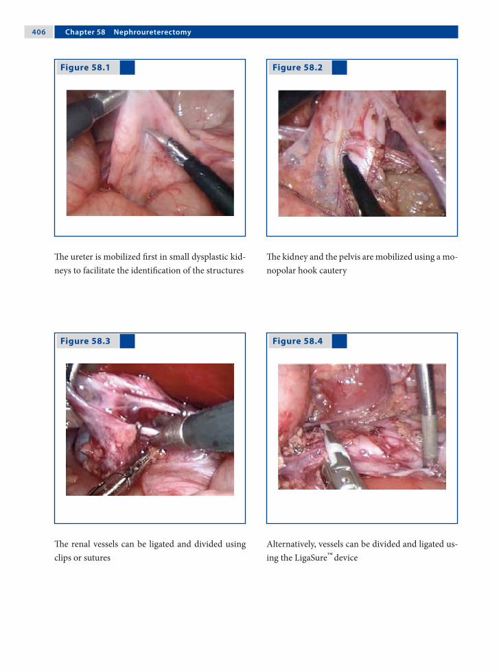
�0� Chapter �� Nephroureterectomy
Figure 58.1 Figure 58.2
Figure 58.3 Figure 58.4
The ureter is mobilized first in small dysplastic kid-neys to facilitate the identification of the structures
The kidney and the pelvis are mobilized using a mo-nopolar hook cautery
The renal vessels can be ligated and divided using clips or sutures
Alternatively, vessels can be divided and ligated us-ing the LigaSure™
device

Benno M. Ure and Martin L. Metzelder �0�
Recommended Literature
1. Jesch NK, Metzelder ML, Kuebler JF, Ure BM (2006) Laparoscopic transperitoneal nephrectomy is feasible in the first year of life and not affected by kidney size. J Urol 176:1177–1179
2. Metzelder ML, Kuebler J, Petersen C, Gluer S, Nustede R, Ure BM (2006) Laparoscopic nephroureterectomy in children: a prospective study on Ligasure™ versus clip/ligation. Eur J Pediatr Surg 16:241–244
3. Najmaldin AS (1999) Transperitoneal laparoscopic ne-phrectomy. In: Bax NMA, Georgeson KE, Najmaldin AS, Valla J-S (eds) Endoscopic Surgery in Children. Spinger, New York, pp 371–378
Figure 58.5 Figure 58.6
The distal ureter is ligated using a suture close to its point of entry in the urinary bladder
The kidney is removed in a specimen retrieval bag (inset) via the enlarged infraumbilical port incision

Surgical Team Position
59.1 Operation Room Setup
59 Transabdominal PyeloplastyJames G. Young and Francis X. Keeley

�10 Chapter �� Transabdominal Pyeloplasty
59.3 Special Instruments
• Gyrus bipolar Trisector® (ACMI-Gyrus, Maple Grove, MN, USA)
• Needle holder
Port Placement Sites
59.2 Patient Positioning
For right transperitoneal pyeloplasty (reverse posi-tions for left) position the patient on left lateral side leaning back at an angle approximately 30° perpen-dicular to table. Support position with strap around table and patient’s lower buttocks. Wedge supports are applied to upper buttock. The patient’s right hand is supported on a padded board. Right knee is straightened; left knee flexed and pillow placed between legs. Positions for right side pyeloplasty shown.
59.4 Location of Access Points
James G. Young and Francis X. Keeley �11
59.5 Indications
1. Primary pelviureteric junction obstruction (PUJO).
2. Secondary PUJO if due to a crossing vessel.3. Treatment is particularly indicated if the patient
is symptomatic or if there is impairment of re-nal function.
59.6 Contraindications
1. Nonfunctioning kidney.2. Active urological sepsis in the affected kidney.3. Coagulopathy.
59.8 Technical Notes
1. Freeing up a reasonable area of the renal pelvis is crucial to a tension-free anastomosis.
2. Resist the urge to place a stent in a retrograde fashion before starting the laparoscopy; in-stead, place the stent in an antegrade fashion af-ter completing the posterior wall of the anasto-mosis. The stent is placed over a guidewire in-troduced through a large-caliber needle. Use a longer stent than usual so that the proximal curl does not interfere with the anastomosis.
3. Suturing the anastomosis can be taxing. Adjust the height of the table to ensure that your shoul-ders are relaxed.
59.7 Preoperative Considerations
1. PUJO should be demonstrated clinically and ra-diologically with ultrasound and diuretic MAG3 (Mercapto Acetyl Tri Glycine) renography.
2. The Whitaker test may be considered if reno-graphy is indeterminate.
3. Secondary causes should be excluded and on-table retrograde pyelography considered.
4. Give gentamicin prophylaxis on induction of anesthesia.
59.9 Procedure Variations
Retroperitoneal approach: the dissection is more direct, but the anastomosis can be much more chal-lenging (see Chap. 60).
59.10 Laparoscopic Transabdominal Pyeloplasty
Please see Figs. 1–4.

�12 Chapter �� Transabdominal Pyeloplasty
Figure 59.1 Figure 59.2
Figure 59.3 Figure 59.4
The right kidney is exposed by mobilizing colon. The lower pole is identified and is retracted later-ally to expose the renal pelvis (RP). The renal pel-vis is dissected circumferentially and traced to the ureter (U)
If the renal pelvis is collapsed or there is little hydro-nephrosis, the ureter can be located and dissected up to the renal pelvis. Not infrequently, a lower pole vessel (V) is seen crossing the ureter
Dismembered pyeloplasty is performed with a stay suture in place to prevent the ureter retracting. The ureter is widely spatulated
Ureteropelvic anastomosis is performed with three interrupted absorbable sutures at the apex of the spatulation followed by a continuous running su-ture. A Robinson drain is inserted at the end of the procedure. VS Absorbable suture (Vicryl™; Ethicon, Somerville, NJ, USA)

James G. Young and Francis X. Keeley �13
Recommended Literature
1. Davenport K, Minervini A, Timoney AG, Keeley FX Jr (2005) Our experience with retroperitoneal and trans-peritoneal laparoscopic pyeloplasty for pelviureteric junction obstruction. Eur Urol 48:973–977
2. Piaggio LA, Franc-Guimond J, Noh P, Wehry M, Figueroa T, Barthold J, González R (2007) Transperi-toneal laparoscopic pyeloplasty for primary repair of ureteropelvic junction obstruction in infants and chil-dren: comparison with open surgery. J Urol 178:1579–1583
3. Smaldone MC, Sweeney DD, Ost MC, Docimo SG (2007) Laparoscopy in paediatric urology: present sta-tus. BJU Int 100:143–150

Surgical Team Position
60.1 Operation Room Setup
60 Retroperitoneal Robot-Assisted PyeloplastyLars H. Olsen and Troels M. Jørgensen
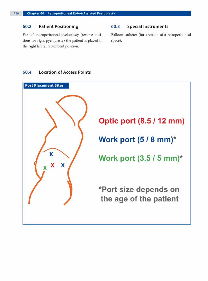
�1� Chapter �0 Retroperitoneal Robot-Assisted Pyeloplasty
60.3 Special Instruments
Balloon catheter (for creation of a retroperitoneal space).
Port Placement Sites
60.2 Patient Positioning
For left retroperitoneal pyeloplasty (reverse posi-tions for right pyeloplasty) the patient is placed in the right lateral recumbent position.
60.4 Location of Access Points

Lars H. Olsen and Troels M. Jørgensen �1�
60.5 Indications
1. Pelviureteric junction obstruction (PUJO).2. Treatment is particularly indicated if the patient
is symptomatic or there is impairment of renal function.
3. Kidney stones in addition to PUJO.
60.6 Relative Contraindications
1. Re-do procedures.2. Infants below 6 months–1 year.
60.8 Technical Notes
1. The DeBakey grasper is manipulated by the sur-geon’s left hand.
2. The surgeon’s right hand manipulates the mo-nopolar hook or scissors and the large needle holder.
3. The assistant assists with other 3.5/5-mm in-struments (scissors, grasper, and suction/irriga-tion) as required.
4. Suturing of the anastomosis is performed using absorbable 5–0 or 6–0 suture material.
60.7 Preoperative Considerations
1. A single dose of antibiotics is administered if the placement of a double-J ureteral stent is planned or indwelling catheters are expected to be removed after 24 h.
2. Epidural catheter placement should be consid-ered.
3. Patients are placed with the upper leg stretched and the lower leg flexed. A small gel cushion or roll should be placed under the contralateral iliac crest. Internal rotation of the upper hip joint should be avoided in older children.
60.9 Procedure Variations
1. Transabdominal pyeloplasty.2. Nondismembered pyeloplasty should be done
only if surgery on the lower ureter is antici-pated.
60.10 Robot-Assisted Laparoscopic Retroperitoneal Pyeloplasty
Please see Figs. 1–10.

�1� Chapter �0 Retroperitoneal Robot-Assisted Pyeloplasty
Figure 60.1 Figure 60.2
Figure 60.3 Figure 60.4
The patient is positioned with the upper leg stretched and the lower leg flexed. Position shown for left side pyeloplasty
The retroperitoneal space is developed with a sim-ple surgical-glove-finger-catheter balloon. Do not inflate more than 200–300 ml of air/saline (to avoid tearing of the peritoneum). In adolescents, com-mercially available balloon dilatators can be used
A wide opening of Gerota’s fascia is preferred. The dissection is kept close to the back muscles and the psoas muscle
Dissection is carried out cranially to caudally, from the pelvis down to the ureter, in the lesser-vascular-ized areas

Lars H. Olsen and Troels M. Jørgensen �1�
Figure 60.5 Figure 60.6
Figure 60.7 Figure 60.8
Stay sutures are placed on both ends of the pelvis and the upper end of the ureter. This helps to keep blood and urine out of the operating field. The stay sutures further align the ureter and the pelvis and facilitate suturing of the anastomosis
The pelvis and ureter are dismembered. The ste-notic area of the ureter is preserved and is used as a handle during suturing. If an aberrant vessel is present, the ureter is transposed before the stay su-ture is placed
The ureter is spatulated for a length of approxi-mately 2 cm
One half, either anterior or posterior (as preferred), of the anastomosis is closed with 5-0 or 6-0 run-ning sutures

�20 Chapter �0 Retroperitoneal Robot-Assisted Pyeloplasty
Recommended Literature
1. Kutikov A, Nguyen M, Guzzo T, Cantar D, Casale P (2006) Robot assisted pyeloplasty in the infant – les-sons learned. J Urol 176:2237–2239
2. Lee RS, Retik AB, Borer JG, Peters CA (2006) Pediatric robot assisted laparoscopic dismembered pyeloplasty: comparison with a cohort of open surgery. J Urol 175:683–687
3. Olsen LH, Rawashdeh YF, Jorgensen TM (2007) Pedi-atric robot assisted retroperitoneoscopic pyeloplasty: a 5-year experience. J Urol 178:2137–2141
Figure 60.9 Figure 60.10
A guidewire is inserted through the 5-mm assistant port. A desired-size double-J stent is pushed down the guidewire to the bladder until the upper end is visible. The guidewire is removed and the upper coil of the stent is placed in the pelvis
The second half of the anastomosis is then com-pleted. A drain is not necessary when opting for retroperitoneal access. The fascia of the camera port and the medial assistant port are closed before skin closure

Surgical Team Position
61.1 Operation Room Setup
61 Transvesicoscopic Ureteric ReimplantationJean-Stéphane Valla

�22 Chapter �1 Transvesicoscopic Ureteric Reimplantation
61.3 Special Instruments
• Cystoscopy set• 3-mm instruments • 3-mm ports
Port Placement Sites
61.2 Patient Positionings
Supine in the modified lithotomy position with ab-ducted thighs. The lower part of the abdomen and genitalia are draped in a sterile fashion.
61.4 Location of Access Points

Jean-Stéphane Valla �23
61.5 Indications
1. Persistent high-grade reflux.2. Failure of endoscopic submucosal injection.3. Major anatomical anomalies: duplex system, re-
flux of ureterocele incision, reflux-associated with large diverticulum.
61.6 Contraindications
1. Children under 6 months of age (the working space is too small).
2. Huge megaureter.
61.8 Technical Notes
1. First step: the bladder is distended with saline instilled using transureteral cystococopy. The three ports are placed under cystoscopic guid-ance. The bladder wall must be approximated to the abdominal wall to avoid trocar dislodge-ment during the procedure by the use of special ports (self-retaining ports with balloon or um-brella tips) or a suture passed percutaneously.
2. Second step: the bladder is insufflated with car-bon dioxide using pressures of 8–10 mmHg. The ureteral reimplantation is performed in a manner similar to that followed in the open procedure.
3. Leave a bladder catheter (transurethral or supra-pubic) for 2 days postoperatively.
4. Try to close the bladder wall port incisions.
61.7 Preoperative Considerations
1. Verify the sterility of the patient’s urine.2. Complete a preoperative assessment of urinary
tract to exclude any bladder obstruction or dys-function.
3. Obtain informed consent from the parents since this is a new technique that is not yet considered as the gold-standard in the management of ves-icoureteral reflux.
61.9 Procedure Variations
1. The urethra could be used to pass a 3-mm in-strument and could be used as the third operat-ing access.
2. The urethra could also be used to place a cath-eter that can be utilized to aspirate smoke and urine during the procedure.
3. A mechanical camera holder is useful to obtain stable vision at the time of suturing.
4. There is no need to occlude the urethra, even in female patients, as the gas leak through the ure-thra is minimal.
61.10 Transvesicoscopic Cohen’s Right-Side Ureteric Reimplantation
Please see Figs. 1–11.

�2� Chapter �1 Transvesicoscopic Ureteric Reimplantation
Figure 61.1 Figure 61.2
Figure 61.3 Figure 61.4
Schematic representation of the transvesicoscopic ureteric reimplantation procedure showing the points of port placement and intervention
The patient is positioned toward the end of the op-erating table since this procedure involves the si-multaneous implementation of cystoscopy
The ports are inserted under cystoscopic visualiza-tion. The ports are placed closer to the umbilicus in small children (bladder = abdominal organ) and closer to the pubis in older children (bladder=pelvic organ)
The surgeon stands toward the head of the patient in children under the age of 5 years and on the left side of the patient in older children
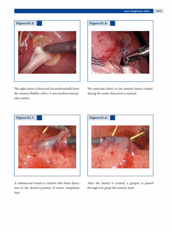
Jean-Stéphane Valla �2�
Figure 61.5 Figure 61.6
Figure 61.7 Figure 61.8
The right ureter is dissected circumferentially from the urinary bladder with a 3-mm hooked monop-olar cautery
The muscular defect or the ureteric hiatus created during the ureter dissection is sutured
A submucosal tunnel is created with blunt dissec-tion to the desired position of ureter reimplanta-tion
After the tunnel is created, a grasper is passed through it to grasp the ureteric stent

�2� Chapter �1 Transvesicoscopic Ureteric Reimplantation
Recommended Literature
1. Kutikov A, Guzzo TJ, Canter DJ, Casale P (2006) Initial experience with laparoscopic transvesical ureteral re-implantation at the Children’s Hospital of Philadelphia. J Urol 176:2222–2225
2. Ogan K, Pohl HG, Carlson D, Belaman AB, Rush-ton HG (2001) Parental preferences in the manage-ment of vesicoureteral reflux. J Urol 166:240–243
3. Yeung CK, Sihoe JD, Borzi PA (2005) Endoscopic cross-trigonal ureteral reimplantation under carbon dioxide bladder insufflation: a novel technique. J En-dourol 19:295–299
Figure 61.9 Figure 61.10
Figure 61.11
The ureter is then passed through the tunnel and sufficiently exposed on the other side
After resection of the distal part of the ureter a ure-teroneocystostomy is performed with interrupted sutures
The procedure is completed with circumferential interrupted sutures to secure the ureter to its new position

Surgical Team Position
62.1 Operation Room Setup
62 STING Procedure for Vesicoureteral RefluxPrem Puri

�2� Chapter �2 STING Procedure for Vesicoureteral Reflux
62.3 Special Instruments
• Cystoscope• Puri flexible catheter (Karl Storz, Tuttlingen,
Germany)• Deflux™ (Q-Med Scandinavia, Uppsala, Swe-
den)
62.2 Patient Positioning
Toward the end of the table in a supine position with arms tucked to the side.
62.4 Location of Access Points

Prem Puri �2�
62.5 Indications
1. High-grade primary vesicoureteral reflux (VUR; grade III–V).
2. VUR in duplex renal systems.3. VUR secondary to neuropathic bladder and
posterior urethral valves.4. VUR in failed reimplanted ureters.5. VUR into refluxing ureteral stumps.
62.7 Technical Notes I
1. All cystoscopes available for infants and chil-dren can be used for this procedure.
2. The disposable Puri flexible catheter or a rigid metallic catheter can be used for injection.
3. A 1-ml syringe filled with Deflux™ is attached to the injection catheter.
4. Under direct vision through the cystoscope, the needle is introduced under the bladder mucosa 2–3 mm below the affected ureteral orifice at the 6 o’clock position.
62.8 Technical Notes II
1. In grades IV and V reflux with wide ureteral ori-fices, the needle should be inserted not below, but directly into the affected ureteral orifice.
2. The needle is advanced about 4–5 mm under the mucosa and the injection started slowly.
3. As the Deflux™ is injected a bulge appears in the floor of the submucosal ureter. A correctly placed injection creates the appearance of a nip-ple on the top of which is a slit-like or inverted crescent orifice.
4. Patients are treated as day cases and a void-ing cystourethrogram and ultrasound are per-formed 6–12 weeks after discharge.
62.6 Preoperative Considerations
62.6.1 Tissue-Augmenting Substances
The tissue-augmenting substance most commonly used for subureteral injection is dextranomer/hyal-uronic acid copolymer (Deflux™). It consists of mi-crospheres in 1% high-molecular-weight sodium hyaluronan solution. Each milliliter of Deflux con-tains 0.5 ml sodium hyaluronan and 0.5 ml dextra-nomer.

�30 Chapter �2 STING Procedure for Vesicoureteral Reflux
Figure 62.1
Figure 62.2
62.9 STING Procedure for the Treatment of VUR
Please see Figs. 1–14.
Equipment set-up for the STING procedure is shown here. A-1ml syringe prefilled with Deflux™ is attached to the Puri flexible catheter for injection and introduced through a cystoscope
Schematic representation of the STING procedure. The needle is introduced under the mucosa of the affected ureteral orifice at the 6 o’clock position (a) and is advanced 4–5 mm before the injection is started (b). At the end of the injection the ureteral orifice is slit-like (c)

Prem Puri �31
Figure 62.3 Figure 62.4
Figure 62.5 Figure 62.6
Endoscopic appearance of a grade III refluxing ure-teral orifice
Endoscopic appearance of STING. A correctly placed Deflux™
implant gives the appearance of a nipple on top of which is a slit-like orifice
Endoscopic appearance of a grade V refluxing ure-teral orifice prior to injection
Endoscopic appearance of a grade V refluxing ureteral orifice with the injection in progress

�32 Chapter �2 STING Procedure for Vesicoureteral Reflux
Figure 62.9 Figure 62.10
Figure 62.7 Figure 62.8
During the injection the needle is slowly withdrawn until a “volcanic” bulge of paste is seen
A correctly placed injection creates the appearance of a nipple with a slit like orifice on the top of it
Endoscopic appearance of a grade V wide ureteral orifice in an infant
The needle for injection is inserted under the mu-cosa directly inside the affected ureteral orifice

Prem Puri �33
Figure 62.11 Figure 62.12
Injection in progress showing a bulge of paste ap-pearing in the floor of the affected ureteral orifice
At the end of the injection the ureteral orifice has a slit-like appearance

�3� Chapter �2 STING Procedure for Vesicoureteral Reflux
Figure 62.13 Figure 62.14
Recommended Literature
1. Menezes M, Puri P (2007) The role of endoscopic treat-ment in the management of grade 5 primary vesico-ureteral reflux. Eur Urol 52:1505–1510
2. Puri P (2006) Endoscopic treatment of vesicoureteral reflux. In: Puri P, Höllwarth ME (eds) Pediatric Sur-gery (Springer Surgery Atlas Series). Springer Heidel-berg, pp 493–498
3. Puri P, Pirker M, Mohanan M, Dawrant M, Dass L, Colhoun E (2006) Subureteral dexranomer\hyaluronic acid injection as first line treatment in the management of high grade vesicoureteral reflux. J Urol 176:1856–1860
Voiding cystourethrogram showing bilateral grade V reflux
Voiding cystourethrography in the same child showing no evidence of reflux 3 months after the STING procedure

Surgical Team Position
63.1 Operation Room Setup
63 Varicocele LigationOliver J. Muensterer

�3� Chapter �3 Varicocele Ligation
63.3 Special Instruments
• Ultracision® shears (Johnson & Johnson Med-ical Products, Ethicon Endo-Surgery, Cincin-nati, OH, USA)
• Endoscopic clip applicator
Port Placement Sites
63.2 Patient Positioning
Supine position with arms tucked to the side; the ipsilateral side may be abducted. The positioning shown here is for left-side varicocele, which occurs more frequently.
63.4 Location of Access Points

Oliver J. Muensterer �3�
63.5 Indications
Symptomatic varicocele (low sperm count, scrotal pain, testicular atrophy compared to the contralat-eral side, severe cosmetic impairment).
63.6 Contraindications
1. Suspected malignancy of the ipsilateral kidney.2. Other testicular or scrotal pathologies mimick-
ing varicocele.3. Previous surgery that may have compromised
the blood supply to the affected testes (orchido-pexy).
63.8 Technical Notes
1. Tilting the table with the ipsilateral side up and head down may facilitate exposure of the sper-matic vessels.
2. A large incision in the peritoneum should be made to grasp all identified vessels and to mo-bilize them well into the abdominal cavity. This helps to facilitate a complete and safe ligation.
63.7 Preoperative Considerations
1. In children under 5 years or right-sided vari-cocele, use ultrasound to rule out renal tumor or hydronephrosis causing mechanical compres-sion of the testicular vein.
2. Usually left-sided (90%); however 9% are bilat-eral and only 1% are right-sided.
3. The recurrence rate is under 4% for mass liga-tion (artery and vein), up to 20% with artery preservation, and 16% for the inguinal open ap-proach.
4. The most common complications are hydrocele formation (7%) and sensory loss in the distribu-tion of the cutaneous femoral lateral nerve.
63.9 Procedure Variations
1. Depending on personal preference and the equipment available, ligation of the spermatic vessels may be performed by electrocautery, ultrasound scissors, or clips.
2. Preoperative subdartos injection of isosulfan blue may help the surgeon to identify and pre-serve the lymphatic vessels during dissection and thereby reduce the risk of postoperative hydrocele formation.
63.10 Laparoscopic Palomo Varicocele Ligation
Please see Figs. 1–6.
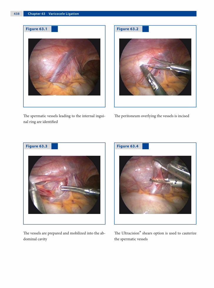
�3� Chapter �3 Varicocele Ligation
Figure 63.1 Figure 63.2
Figure 63.3 Figure 63.4
The spermatic vessels leading to the internal ingui-nal ring are identified
The peritoneum overlying the vessels is incised
The vessels are prepared and mobilized into the ab-dominal cavity
The Ultracision® shears option is used to cauterize the spermatic vessels
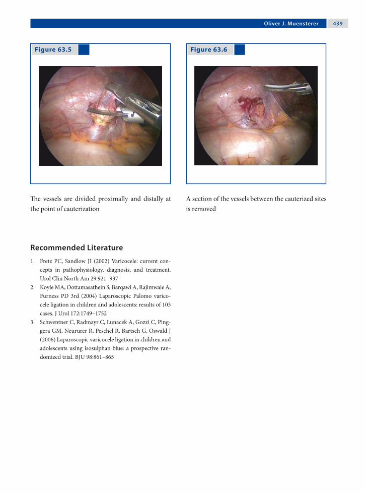
Oliver J. Muensterer �3�
Recommended Literature
1. Fretz PC, Sandlow JI (2002) Varicocele: current con-cepts in pathophysiology, diagnosis, and treatment. Urol Clin North Am 29:921–937
2. Koyle MA, Oottamasathein S, Barqawi A, Rajimwale A, Furness PD 3rd (2004) Laparoscopic Palomo varico-cele ligation in children and adolescents: results of 103 cases. J Urol 172:1749–1752
3. Schwentner C, Radmayr C, Lunacek A, Gozzi C, Ping-gera GM, Neururer R, Peschel R, Bartsch G, Oswald J (2006) Laparoscopic varicocele ligation in children and adolescents using isosulphan blue: a prospective ran-domized trial. BJU 98:861–865
Figure 63.5 Figure 63.6
The vessels are divided proximally and distally at the point of cauterization
A section of the vessels between the cauterized sites is removed

Section 6 Miscellaneous Topics

64.1 Reliance on Electrosurgery
Relatively minimal bleeding, which is a minor ob-stacle with open procedures, may completely ob-scure the view in endoscopic surgery and prevent safe dissection. Therefore, in order to perform min-imal-access procedures, the surgeon must rely more heavily on the energy source for hemostasis and cutting than in open operations. Several problems are inherent in the use of energy sources during laparoscopy.
64.2 Electrosurgery in Fluids
The conductive properties of blood or saline may be less precise than during an open procedure, where a dry operative field is more readily maintained. Ex-cessive application of energy in a the presence of fluids will distort anatomic planes. Thus, it is import-ant that endoscopic surgeons learn to use energy sources to their fullest potential in order to improve the precision of application and avoid tissue injury.
64.3 Principles of Monopolar Surgery
The effects of monopolar electrosurgery are pro-vided by a rapidly alternating electrical current with a frequency of around 500,000 Hz. These high fre-quencies generate heat in the tissues to provide a variety of local effects.
Tissue temperatures may vary with current den-sity in the path present between the active surgical electrode and the return pad.
64.4 Generator Settings
1. In most modern generators, the surgeon selects only the wattage; the voltage and amperage vary and are not controlled independently by the surgeon during the application of energy.
2. Voltage increases automatically as tissue is des-iccated and leads to an increase in resistance.
3. The surgeon may select varying waveforms from the generator.
64.4.1 “Cut” Waveform
1. At lower voltage the “cut” waveform is continu-ous and uninterrupted.
2. The “cut” mode causes intense heating and boil-ing of intracellular contents as a result of the to-and-fro motion of an alternating electrical field.
3. The superficial cells vaporize giving the cutting effect when the electrode is held near the tissue, but not in contact. Hemostasis is poor as less desiccation of deeper tissue occurs.
64.4.2 “Coagulation” Waveform
1. The “coagulation” waveform provides inter-rupted bursts of high-voltage current.
2. The higher voltage of the “coagulation” wave-form enables an electrical charge to penetrate deeper into the tissue or arc for a longer dis-tance to the target tissue.
3. For the same power settings, the “coagulation” mode provides a higher voltage and lower am-perage compared to the “cut” mode.
64 Electrosurgical InjuriesAmulya K. Saxena

��� Chapter �� Electrosurgical Injuries
64.5 Fulguration
1. Fulguration is a technique that provides superfi-cial desiccation of tissues by arcing current from the electrode through the air to the adjacent tis-sue.
2. The most effective fulguration occurs with a high-voltage generator operated in the “coagu-lation” mode, as higher voltages are capable of generating longer arcing to the tissue.
64.5.1 Effects of Fulguration
1. Superficial tissue effects occur because the elec-trode has not made contact with the tissue and part of the energy is dissipated as lightning.
2. Fulguration is quite useful, but the high-voltage waveforms used increases the risk of insulation failure and capacitive coupling.
3. Spray fulguration may result in acute elevation of intra-abdominal pressures, hypotension, and air embolism of the instilled gas.
64.6 Contact Desiccation
1. Contact desiccation occurs when the activated electrode in contact with tissue provides he-mostasis as successive layers of tissue are desic-cated.
2. When the superficial tissue is desiccated, the generator voltage output automatically increases to facilitate deeper tissue effects.
3. Contact desiccation leads to the development of eschar, which may distort anatomic planes.
64.7 Coaptive Coagulation
1. Coaptive coagulation occurs when tissue is compressed within a grasper and current is ap-plied.
2. Desiccation occurs along with the development of a collagen weld of the compressed tissue.
3. This tissue effect can be obtained with either the “cut” or “coagulation” mode. The benefit of the “cut” mode is that a lower voltage is employed.
64.8 Instrument Insulation
1. Conventional insulation is based on the incor-poration of layers of nonconductors around the electrode.
2. Defects in insulation allows the delivery of the entire current to tissues outside the view of the surgeon and yet remains imperceptible to visual inspection.
3. Insulation defects occur as a result of mechan-ical trauma, repeated sterilization, manufactur-ing flaws, and capacitively coupled meltdown.
64.9 Contributors to Insulation Failure
Routine use of the high-voltage “coagulation” cur-rent may actually compromise insulation integrity. The higher the voltage, the greater the risk that the current will break through weak insulation. Using a lower voltage may reduce the wear on the insula-tion and minimize the chance that the current can escape through hairline cracks.

Amulya K. Saxena ���
64.10 Areas of Electrode Insulation Failure
The hazards of insulation failure depend on the area of insulation breach. It is important to understand the parts of an electrode in order to have a better overview of the type of injuries that failure of insu-lation can causes.
An electrode consists of:1. An exposed handle (in the surgeons’ hand).2. An area within the port.3. The shaft of the electrode.4. The electrode tip (desired zone of delivery).
64.10.1 Hazards of Insulation Failure
1. Exposed metal in the handle of the instrument may cause burns to the surgeon‘s hands.
2. The signs of insulation failure within the port by lower-frequency electrical currents can cause neuromuscular stimulation and jerking of the abdominal wall or diaphragm.
3. Defects in the electrode shaft may cause an in-jury outside the view of the surgeon.
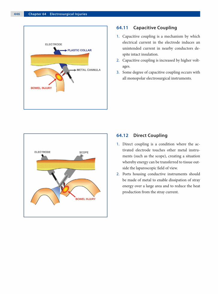
��� Chapter �� Electrosurgical Injuries
64.11 Capacitive Coupling
1. Capacitive coupling is a mechanism by which electrical current in the electrode induces an unintended current in nearby conductors de-spite intact insulation.
2. Capacitive coupling is increased by higher volt-ages.
3. Some degree of capacitive coupling occurs with all monopolar electrosurgical instruments.
64.12 Direct Coupling
1. Direct coupling is a condition where the ac-tivated electrode touches other metal instru-ments (such as the scope), creating a situation whereby energy can be transferred to tissue out-side the laparoscopic field of view.
2. Ports housing conductive instruments should be made of metal to enable dissipation of stray energy over a large area and to reduce the heat production from the stray current.

Amulya K. Saxena ���
64.13 Precaution in Injury Prevention
1. The active electrode should not be in close prox-imity to or touching another metal instrument before the generator is activated.
2. It is important to confirm that the electrode is touching the targeted tissue, and only that tis-sue, before the generator is activated.
3. When the targeted tissue is coagulated, the im-pedance increases and the current may arc to adjacent tissue, following the path of least resis-tance.
64.14 All-Metal-Port System
The all-metal-port system is appropriate since all capacitive currents will be safely dispersed through the greater surface area provided by the chest or ab-dominal wall, thereby reducing current density. The surface area of the metal port will be adequate to safely dissipate any current buildup on the port with-out significant heat production or tissue damage.
64.15 All-Plastic-Port System
When using an all-plastic system, the definition of a capacitor can be eliminated. Instead of two conduc-tors separated by a nonconductor, there is now the conductive electrode, covered by nonconductive in-sulation, surrounded by the nonconductive port. A capacitor no longer exists and concerns over capaci-tively coupled current can be eliminated.
64.16 Hybrid Port (Metal and Plastic)
This system consists of a metal sleeve that is held in place with a plastic anchor. In this system, the coup-led current is not able to disperse safely because the port is held in place by a nonconductive plastic an-chor. The current that is coupled onto the metal port can only complete the circuit by discharging to tissue that it may encounter within the cavity. This can potentially create a significant injury.
64.17 Monopolar Electrosurgery Guidelines
1. All insulations should be inspected for defects.2. Lower-power settings should be used for both
cutting and coagulation to reduce the possibili-ties of insulation failure, capacitance, and injury.
3. Apply a low-voltage waveform whenever pos-sible.
4. Low-voltage waveforms reduce the amount of ca-pacitively coupled energy that can be produced.
5. Brief activation is better than a prolonged one.6. Metal-to-metal sparking (direct coupling)
should be avoided. The electrode should be acti-vated only when it is touching the target tissue.
7. Hybrid port systems should be avoided.
Recommended Literature
1. Jones CM, Pierre K, Nicoud I, Stain S, Melvin W 3rd (2006) Electrosurgery. Curr Surg 63:458–463
2. Meijer DW (2006) Safety of the laparoscopy setup. Minim Invasive Ther Allied Technol 12:125–128
3. Wang K, Advincula AP (2007) “Current thoughts” in electrosurgery. Int J Gynaecol Obstet 97:245–250

65.1 Incidence of Complications
The true incidence of complications in endoscopic surgery is not known. However, awareness of the possible complications at various levels of proced-ures is important in providing safer endoscopic sur-gical expertise. Technical difficulties encountered during the learning curve should be recognized and accepted. There is no substitute for practice and training to improve skills and outcome.
65.2 Major Areas of Concern
1. Anesthetic-related complications.2. Insufflated gases.3. Access-related complications.4. Instrumentation.5. Blood loss during the procedure.6. Visceral injuries.7. Port-site complications.8. Thermal damage.
65.2.1 Predisposition to Anesthetic Problems
Some features of endoscopic surgery predispose to specific anesthetic complications.1. The use of a steep Trendelenburg position and
the distension of the abdomen may both reduce excursion of the diaphragm.
2. Carbon dioxide (CO2) can be absorbed, particu-larly during prolonged operations.
3. The vasovagal reflex may produce shock and collapse, especially if the anesthesia is not deep enough.
65.2.2 Mediastinal Emphysema
1. Gas may extend from the pneumoperitoneum into the mediastinum and form mediastinal emphysema.
2. Large emphysema may cause cardiac embar-rassment, which will be diagnosed by the anes-thetist.
3. In cases of large mediastinal emphysema, the endoscopic procedure must be abandoned and as much gas as possible evacuated.
65 Complications in Endoscopic SurgeryThomas Petnehazy and Amulya K. Saxena
��0 Chapter �� Complications in Endoscopic Surgery
65.2.3 Extraperitoneal Gas Insufflation
1. Failure to introduce the Veress needle or port into the peritoneal cavity may produce extra-peritoneal emphysema.
2. The typical spider-web appearance caused by preperitoneal insufflation will be seen when the telescope reaches the end of the port.
3. The scope should be withdrawn and attempts made to express the gas.
65.2.4 Pneumothorax During Laparoscopy
1. Pneumothorax should be suspected if there is difficulty in ventilating the patient during high port insertion during a laparoscopic procedure.
2. There may be a contralateral mediastinal shift and increased tympanism over the affected area.
3. The procedure should be abandoned and the gas allowed to escape.
4. Occasionally, postoperative mechanical ventila-tion and insertion of a pleural tube may be neces-sary.
65.2.5 Pneumo-omentum
1. This occurs when the omentum is penetrated by the Veress needle or port.
2. A raised insufflation pressure should lead the surgeon to suspect an error in the position of the needle or port.
3. The condition does not pose any major problems unless an omental blood vessel is punctured.
65.2.6 Urinary Bladder Injuries
1. Routine catheterization of the bladder should prevent bladder-penetration injuries.
2. The bladder peritoneum should be carefully in-spected to ensure that no significant injury has been caused.
3. Simple punctures can be treated conservatively with postoperative bladder drainage.
4. Possible “patent urachus” must be kept in mind when opting for an infraumbilical access.
65.2.7 Gastrointestinal Tract Injuries
1. Certain conditions such as distension of the gastrointestinal tract or adhesions of the bowel to the abdominal wall may predispose to injury.
2. Bilious discharge or fecal soiling indicate gas-trointestinal tract injuries and efforts must be made to recognize and repair the problem.
3. During commencement of the procedures, the gastrointestinal tract should be examined care-fully for injuries or perforation.
65.2.8 Vascular Injuries
1. The Veress needle has been associated more commonly with vascular injuries.
2. The loose areolar tissue anterior to the aorta can allow accumulation of a considerable amount of blood before frank intra-abdominal bleeding is seen.
3. Dramatic collapse may result from penetration of a major vessel, but the bleeding may not be immediately evident if it is retroperitoneal.
Thomas Petnehazy and Amulya K. Saxena ��1
65.2.9 Gas Embolism
1. Intravascular insufflation of gas may lead to gas embolism or even death. This can happen when the Veress needle is used.
2. The patient should be turned on to the left lat-eral position and, if immediate recovery does not take place, cardiac puncture is the last op-tion that can be performed to release the gas.
65.2.10 CO2-Associated Complications
1. Gas embolism is possible, but uncommon, be-cause CO2 is highly soluble and is reabsorbed.
2. Cardiac arrhythmia may occur due to excessive absorption of CO2.
3. Postoperative pain is common with CO2 insuf-flation due to peritoneal irritation, which is a re-sult of conversion of CO2 to carbonic acid.
65.2.11 Hepatic and Splenic Injuries
1. These injuries may occur when ports are placed just above the level of the diaphragm in video-assisted thoracoscopic procedures.
2. Evaluation of the chest film prior to surgery, with special attention paid to the level of the dia-phragm, can help avoid this complication.
3. If hepatic or splenic injury is suspected through thoracoscopy, a concomitant laparoscopy should be performed to evaluate the blood loss and, if possible, the extent of the injury.
65.2.12 Abdominal Wall Vessel Injury
1. Severe bleeding can occur the from puncture of the deep inferior epigastric artery.
2. The artery is at risk during the insertion of sec-ondary ports and trocars.
3. Injury may be prevented by transilluminating the abdominal wall before insertion in a thin patient, or by visualizing the artery laparoscop-ically as it runs lateral to the obliterated umbili-cal artery.
65.2.12.1 Management of Deep Inferior Epigastric Vessel Injury
1. Diagnosis can be made by the observation of blood dripping or spurting, or the presence of a large hematoma at the site of the secondary port insertion.
2. Options in management include: a) passing a Foley catheter down the port side
and compressing it against the abdominal wall,
b) placing a long-bodied needle suture under laparoscopic control, and
c) occasionally the need to widen the wound and control bleeding.
65.2.13 Stomach Injuries
1. Injuries to the stomach or bowel are always ser-ious.
2. The classical treatment is to perform laparot-omy and suture the bowel in two layers.
3. A skilled surgeon may perform the repair by laparoscopic suturing.

��2 Chapter �� Complications in Endoscopic Surgery
65.2.14 Omental and Richter’s Herniation
1. If the primary port is withdrawn with its valve closed, a piece of omentum can be drawn by the resulting negative pressure into the umbilical wound.
2. Herniation may also occur some hours after the operation.
3. Herniations do not occur commonly with 5-mm skin incisions.
4. Incisions greater than 7 mm should be sutured in layers to prevent formation of a Richter’s hernia.
65.2.15 Intra-abdominal Vascular Injury
1. Injury to minor blood vessels is usually self-limiting or can be controlled by bipolar electro-coagulation.
2. A small leak from a major vein may not be ap-parent immediately, since the intra-abdominal pressure of the pneumoperitoneum and the de-creased venous pressure induced by the Tren-delenburg position may temporarily control it.
65.2.16 Thermal Injuries with Electrosurgery
1. Lateral heat spread may occur with monopolar or bipolar current.
2. It is important to ensure that no other organ is in contact with or near an organ to which elec-tricity is being applied.
3. Lateral spread may also be minimized by keep-ing the forceps blades close together.
4. Build-up of thermal energy may be prevented by intermittent application of energy.
65.2.16.1 Monopolar Coagulation Injuries
1. Thermal injury to organs such as the bowel may also result from leakage of current from the shaft of the instrument.
2. Electrosurgical instruments should be passed through ports and not directly through inci-sions in the chest or abdominal cavity.
3. Long, insulated active electrodes significantly change the physics surrounding the use of high frequency electrosurgical energy.
65.2.17 Thermal Injury to the Bowel
1. The bowel is the most commonly injured organ with electrosurgical applications.
2. Injury may range from minor blanching of the serosa to frank perforation.
3. If blanching is significant, excision of the dam-aged tissue and surgical repair should be per-formed.
4. Failure to recognize the injury may result in de-layed ischemic necrosis at the site of the burn.
65.3 Operating-Table-Related Injuries
1. Injury can be caused to the nerves of the leg and to the hip and sacroiliac joints.
2. Compression of the leg veins may predispose to venous thrombosis.
3. The brachial plexus may be injured if the arm is abducted for an extended surgical procedure
4. The hands may be caught and trapped in mov-ing parts of the table.

Thomas Petnehazy and Amulya K. Saxena ��3
Recommended Literature
1. Philips PA, Amaral JF (2001) Abdominal access com-plications in laparoscopic surgery. J Am Coll Surg 192:525–536
2. Philosophe R (2003) Avoiding complications of lapa-roscopic surgery. Fertil Steril 80:30–39
3. Shirk JG, Johns A, Redwine DB (2006) Complications of laparoscopic surgery: how to avoid them and how to repair them. J Minim Invasive Gynecol 13:352–359
65.4 Foreign Bodies
Occasionally clips, staples, or parts of instruments such as sapphire laser tips may be inadvertently dropped and lost in the peritoneal cavity. They should be removed if they are easily found, but there have been no reports of long-term complica-tions from such foreign bodies.
65.5 Complications with Tissue Spillage
1. Dropped stones from cholecystectomy, or ap-pendicoliths may incite an inflammatory re-sponse and can even lead to abscess formation.
2. Tissue rupture and spillage during removal is also a major problem in endoscopic surgery.
3. Implantation of tumor cells can follow. Port-site metastasis may occur in malignancies.
4. Complications related to tissue spillage can be minimized by the use of specimen retrieval bags.

66.1 Schematic Effects of Lasers
Lasers are now being used routinely in the field of endoscopic surgery. The effects of lasers are ex-hibited on tissues by reflection, absorption, trans-mission, and dispersion. Understanding of these characteristics is important in the safe use of these tools.
66.2 Laser Wavelengths
Lasers are classified according to their wavelength, which determines their characteristics. The more commonly used lasers in medicine are carbon diox-ide (CO2), neodium-doped:yttrium aluminum gar-net (Nd:YAG), argon, and potassium titanyl phos-phate (KTP) lasers.
0.2 0.4 0.6 0.8 1.0 10.0 µmultraviolet blue green yellow red infrared
Excimer Ar, Kr Nd: YAG CO2
Pulse dye He, Ne
66 Lasers in Endoscopic SurgeryAmulya K. Saxena

��� Chapter �� Lasers in Endoscopic Surgery
66.2.1 CO2 Lasers
1. The CO2 laser produces an area of injury that is discrete and reproducible with a depth of less than 1 mm and a zone of thermal necrosis less than one-tenth of 1 mm.
2. This laser is highly precise but a poor coagula-tor.
3. The CO2 laser is used endoscopically to vapor-ize deposits of endometriosis and adhesions.
66.2.2 Nd:YAG Lasers
1. The Nd:YAG laser produces an effect several millimeters below the tissue surface, providing excellent coagulation but poor precision.
2. This property of the Nd:YAG is potentially dan-gerous if the underlying tissue heats and ex-plodes.
3. Reduced thermal injury and a more predictable tissue effect has been achieved with the use of sapphire tips or sculpted fibers.
66.2.3 Argon and KTP 532 Lasers
1. Argon and KTP532 lasers have similar tissue ef-fects between those produced by the CO2 and Nd:YAG laser.
2. The Argon laser has less precision but improved coagulating ability.
3. Argon laser has found endoscopic indications in the treatment of polycystic ovarian disease.
66.3 Overlapping Effects of Lasers
Although lasers differ in wavelengths and manifest their effects at specific depths; there is a degree of overlapping in depth penetration.

Amulya K. Saxena ���
66.4 Contact Versus Noncontact Lasers
The CO2 laser is a noncontact laser and provides the advantage of minimizing tissue trauma due to ma-nipulation. The CO2 laser can also be used at any distance from the tissue with a fairly constant tis-sue effect.
Argon, KTP532, and Nd:YAG lasers are contact lasers, whereby the laser beam is focused at the fiber tip. The power density is reduced significantly as the fiber tip moves away from the tissue.
66.5 Comparative Overview of Lasers
Table 66.1
Characteristic LaserType
CO2 Argon Nd:YAG
Wavelength 10,600nm 514nm 1064nm
Absorption Water Hemoglobin/melanin Tissueprotein
Penetration 1mm 2–3mm 5–7mm
Coagulation Low Medium High
Cutting High Low Medium
Comparison of lasers with regard to their applica-tion, penetration, coagulation, and cutting charac-teristics

��� Chapter �� Lasers in Endoscopic Surgery
66.6.4 Accidental Activation Injuries
Injury can occur from the accidental activation of the laser when it is not in use, especially if another foot pedal is in use for a different instrument such as an electrosurgical instrument. Placing the laser on standby whenever it is not in use will reduce the risk of injury by this mechanism.
66.6.5 Human Error
1. For the CO2 laser, the He/Ne aiming beam should always be visualized prior to firing the laser. As a blind area exists near the end of the scope, the risk of inadvertent injury to the bowel can be significantly reduced by following this precaution.
2. For contact lasers, the tip should always be visu-alized, especially immediately after firing the laser, since the tip remains hot and can burn surrounding structures.
66.6.6 Ignition Injuries
1. The liberal use of irrigating solutions to moisten lap packs, gauze bandages, and drapes in the surgical areas reduces the risk of accidental ig-nition.
2. The use of alcohol and ether solutions should be avoided due to their flammable nature.
3. Anesthesiologists should be informed that flam-mable anesthetic gases are also to be avoided.
66.6.3 Minimizing Redirection Injuries
In endoscopic surgery, the primary risk of injury by reflection is to the patient’s intra-abdominal struc-tures due to the closed nature of surgery. Several methods, such as finely wire-brushed, sand-blasted, or glass-beaded instruments and the use of titanium instead of stainless steel, have helped to reduce the risk of redirection injuries, especially those associ-ated with the CO2 laser.
66.6 Injuries Associated with Lasers
66.6.1 Eye Injuries
1. The Nd:YAG, Argon, and KTP lasers can burn the retina, whereas the CO2 laser can cause cor-neal burns.
2. The eye is particularly susceptible to retinal burns from the Nd:YAG laser because the light is invisible and does not induce a protective blink response.
3. Tinted eyewear filters the wavelength of the spe-cific laser for which it is designed while allowing as many of the other wavelengths to pass in or-der to maximize visibility.
66.6.2 Redirection Injuries
1. One mechanism of injury is the redirection of laser energy from reflective surfaces.
2. The unintentional burning of organs in the pa-tient or burning of the surgeon may occur due to reflections off surgical instruments.
3. The surface of most surgical instruments has a convex curve, which usually causes divergence of laser light after reflection
4. Small dents on instrument surfaces could po-tentially refocus laser energy.

Amulya K. Saxena ���
66.6.7 Bowel Injuries
After extensive laser dissection in the cul-de-sac, the bowel should be inspected for perforation injuries. This can be performed by placing a 30-ml Foley catheter into the rectum and clamping the bowel above the site of dissection. The pelvis is then filled with physiologic solution and a 50% solution of Be-tadine injected through the Foley catheter. Trails of Betadine solution indicate perforation.
66.6.8 Ureteral Injuries
In the case of suspicion of ureteral injury, indigo carmine (5 ml) can be injected intravenously. The appearance of indigo carmine coloring should be present in the Foley catheter and bag within ap-proximately 10 min. As with the detection of bowel injury, underwater trails may be present if injury to the ureter has occurred.
Recommended Literature
1. Gale P, Adeyemi B, Ferrer K, Ong A, Brill AI, Scoccia B (1998) Histologic characteristics of laparoscopic argon beam coagulation. J Am Assoc Gynecol Laparosc 5:19–22
2. Klingler CH, Remzi M, Marberger M, Janetschek G (2006) Haemostasis in laparoscopy. Eur Urol 50:948–956
3. Tulikangas PK, Smith T, Falcone T, Boparai N, Walters MD (2001) Gross and histologic characteristics of lap-aroscopic injuries with four different energy sources. Fertil Steril 75:806–810

67.1 Introduction
LigaSure™ vessel-sealing technology (Valleylab, Boulder, CO, USA) provides a unique combination of pressure and energy to create vessel fusion. It per-manently fuses vessels up to and including 7 mm in diameter and tissue bundles without dissection or isolation. The further advantage of this automated system is that it eliminates the guesswork by minim-izing seal time and maximizing reliability.
67.2 Technology
1. An optimized combination of pressure and en-ergy creates a seal by melting the collagen and elastin in the vessel walls and reforming it into a permanent, plastic-like seal. It does not rely on a proximal thrombus.
2. The unique energy output results in virtually no sticking or charring.
3. The thermal spread from the point of sealing is minimal and ranges from 1 to 2 mm depending on the type of instrument used.
67.3 Instant Response™ Technology
The patented Instant Response™ technology (Valle-ylab, Boulder, CO, USA) features an advanced feed-back system that recognizes changes in tissue 200 times per second, and adjusts the voltage and cur-rent accordingly to maintain the most appropriate power and effectively seal the vessel or tissue bun-dle. When the instrument determines the seal is complete, a tone sounds and output to the hand-piece is automatically discontinued.
The seal can be provided on vessels and tissue bundles without dissection. (Courtesy of Covidien Austria, Brunn am Gebirge, Austria)
67 Vessel-Sealing TechnologyAmulya K. Saxena
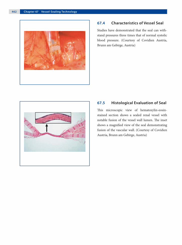
��2 Chapter �� Vessel-Sealing Technology
67.4 Characteristics of Vessel Seal
Studies have demonstrated that the seal can with-stand pressures three times that of normal systolic blood pressure. (Courtesy of Covidien Austria, Brunn am Gebirge, Austria)
67.5 Histological Evaluation of Seal
This microscopic view of hematoxylin-eosin-stained section shows a sealed renal vessel with notable fusion of the vessel wall lumen. The inset shows a magnified view of the seal demonstrating fusion of the vascular wall. (Courtesy of Covidien Austria, Brunn am Gebirge, Austria)

Amulya K. Saxena ��3
67.7 Generator
The generator produces a high-current, low-volt-age output that corresponds to at least four times the current of a standard electrosurgery generator, with one-fifth to one-twentieth the amount of volt-age. (Courtesy of Covidien Austria, Brunn am Ge-birge, Austria)
67.7.1 LigaSure™ V Lap
The LigaSure™ V Lap device has a 5-mm diameter with a 32-cm-long shaft. The 15° curved Mary-land 18-mm electrode length offers a seal width of 2–4 mm with an average thermal spread of ap-proximately 2 mm. (Courtesy of Covidien Austria, Brunn am Gebirge, Austria)
67.6 Instrument Tip
The instrument tips are designed to dissect, seal, and cut. This offers the advantage of fewer instru-ment exchanges during procedures. (Courtesy of Covidien Austria, Brunn am Gebirge, Austria)

��� Chapter �� Vessel-Sealing Technology
67.7.2 LigaSure™ Atlas Sealer/Divider
The LigaSure™ Atlas sealer/divider device has a 10-mm diameter with a 37-cm-long shaft. The straight, 22-mm long electrode offers a seal width of 6 mm with average thermal spread of approximately 2 mm. (Courtesy of Covidien Austria, Brunn am Gebirge, Austria)
67.7.3 LigaSure™ V Sealer/Divider
The LigaSure™ V sealer/divider device has a 5-mm diameter with a 37-cm-long shaft. The straight, 18-mm-long electrode offers a seal width of 4.62 mm with average thermal spread of approx-imately 1.5 mm. (Courtesy of Covidien Austria, Brunn am Gebirge, Austria)
67.8 Foot Pedal Control
The LigaSure™ generator can be operated option-ally with a foot pedal control. The LigaSure™ Atlas 20 cm, which was developed for open surgical pro-cedures, is the only instrument that needs to be ac-tivated through a foot pedal. (Courtesy of Covidien Austria, Brunn am Gebirge, Austria)

Amulya K. Saxena ���
67.9 LigaSure™ Vessel-Sealing Technology Advances
67.9.1 ForceTriad™ Energy Platform
In order to further improve vessel technology, the ForceTriad™ energy (Valleylab, Boulder, CO, USA) platform has been introduced with TissueFect™ sensing technology. (Courtesy of Covidien Austria, Brunn am Gebirge, Austria)
67.9.2 Thermal Spread Profile
Thermal spread can be evaluated using thermo-graphy. The histogram profile shown here demon-strates the lateral thermal spread of 2 mm at the point of application. (Courtesy of Covidien Austria, Brunn am Gebirge, Austria)

��� Chapter �� Vessel-Sealing Technology
67.9.3 Advantages of the ForceTriad™
1. The ForceTriad™ energy platform has an im-proved tissue-sensing, closed-loop control of 3333 decisions per second (vs. 200 decisions per second for the original LigaSure™ generator).
2. The ForceTriad™ energy platform utilizes Tis-sueFect™ sensing technology (Valleylab, Boul-der, CO, USA), a control system that was de-signed to precisely manage energy delivery, cre-ating a range of options for a desired tissue ef-fect.
67.9.4 TissueFect™ Sensing Technology
1. TissueFect™ sensing technology actively moni-tors changes in tissue impedance and provides a real-time adjustment control of the energy out-put.
2. It offers faster fusion cycles (average fusion cycle time of 2–4 s in most surgical situations).
3. It provides more flexible fusion zones.4. Less desiccation of tissue is achieved.5. Consistent controlled tissue effects are possible.
Acknowledgment
Covidien Austria, Brunn am Gebirge, Austria.
Recommended Literature
1. Hruby GW, Marruffo F, Durak E, Collins S, Pierora-zio P, Humphrey P, Mansukhani M, Landman L (2007) Evaluation of surgical energy devices for vessel seal-ing and peripheral energy spread in a porcine model. J Urol 178:2689–2693
2. Matthews BD, Pratt BL, Backus CL, Kercher KW, Mo-stafa G, Lentzner A, Lipford EH, Sing RF, Heniford BT (2001) Effectiveness of the ultrasonic coagulating shears, LigaSure vessel sealer, and surgical clip appli-cation in biliary surgery: a comparative analysis. Am Surg 67:901–906
3. Romano F, Caprotti R, Franciosi C, De Fina S, Co-lombo G, Sartori P, Uggeri F (2002) Laparoscopic sple-nectomy using LigaSure. Preliminary experience. Surg Endosc 16:1608–1611

68.1 Introduction
The Ultracision® harmonic scalpel (Johnson & John-son Medical Products, Ethicon Endosurgery, Cin-cinnati, OH, USA) is the first ultrasonic surgi-cal device for cutting and coagulation. It provides atraumatic surgical dissection and hemostasis us-ing direct application of ultrasound. With the Ul-tracision® harmonic scalpel, no electric current is sent through the patient. Hence, all the risks associ-ated with the direct use of electric current are thus avoided.
68.2 Indications
The Ultracision® harmonic scalpel is indicated for soft-tissue incisions when bleeding control and minimal thermal injury are desired. The instrument can be used as an adjunct to or substitute for elec-trocautery, lasers, and steel scalpels.
68.3 Contraindications
1. Bone incisions.2. Contraceptive tubal ligation.
68.4 Components
The Ultracision® harmonic scalpel system consists of the following components:1. Generator.2. Handpiece with connecting cable.3. Foot switch.4. Coagulating shears.5. Blade system (5 and 10 mm).
68 Harmonic Scalpel TechnologyJulia Seidel and Amulya K. Saxena

��� Chapter �� Harmonic Scalpel Technology
68.4.1 Generator
The Generator is a microprocessor-controlled power supply that drives the acoustic transducer system. (Courtesy of Johnson & Johnson Medical Products, Ethicon Endo-Surgery, Vienna, Austria)
68.4.2 Handpiece
The ergonomic handpiece converts the electrical en-ergy from the generator into mechanical ultrasound vibrations. These vibrations are transmitted to the at-tached Ultracision® harmonic scalpel device. (Cour-tesy of Johnson & Johnson Medical Products, Ethi-con Endo-Surgery, Vienna, Austria)

Julia Seidel and Amulya K. Saxena ���
68.4.3 Foot switch
The Foot switch is used to activate the output of the generator. It has two pedals: With the left pedal, one of five ultrasound energy levels previously selected on the generator will be activated. The right pedal fixes the level at 5. (Courtesy of Johnson & Johnson Medical Products, Ethicon Endo-Surgery, Vienna, Austria)
68.4.4 Laparosonic Coagulating Shears
The laparosonic coagulating shears (LCS) is a multi-functional device that has been developed to use the full potential of ultrasound technology. It cuts, coagulates, grasps, and dissects to improve overall procedural efficiency. (Courtesy of Johnson & John-son Medical Products, Ethicon Endo-Surgery, Vi-enna, Austria)
68.4.4.1 Shear Tip Variations
Shear tips may be straight or curved (inset). The straight shear tips are also available in (1) knife-down or (2) blunt variations. (Courtesy of John-son & Johnson Medical Products, Ethicon Endo-Surgery, Vienna, Austria)

��0 Chapter �� Harmonic Scalpel Technology
68.4.5 Harmonic Scalpel Blades: 10 mm
There a two types of 10-mm blade: ball coagula-tor (top) and dissecting hook (bottom). (Courtesy of Johnson & Johnson Medical Products, Ethicon Endo-Surgery, Vienna, Austria)
68.4.6 Harmonic Scalpel Blades: 5 mm
There are four types of 5-mm blades: (a) curved blade, (b) sharp hook, (c) dissecting hook, and (d) ball coagulator. (Courtesy of Johnson & Johnson Medical Products, Ethicon Endo-Surgery, Vienna, Austria)

Julia Seidel and Amulya K. Saxena ��1
68.5 Comparison of Tissue-Sealing Technologies
Harmonic scalpel technology controls bleeding by captive coagulation at low temperatures ranging from 50 to 100ºC. By contrast, electrosurgery and lasers coagulate by burning (obliterative coagula-tion) at higher temperatures (150–400ºC). Blood and tissue are desiccated and oxidized (charred), forming eschar that covers and seals the bleed-ing area. Rebleeding can occur when blades are re-moved during electrosurgery, as they stick to tissue and disrupt the eschar.

��2 Chapter �� Harmonic Scalpel Technology
68.6 Transducer Technology
1. The transducer, found in the handpiece, consists of piezoelectric ceramics that expand and con-tract to convert the electrical energy from the generator into mechanical vibration.
2. The ultrasonic vibration is transmitted from the transducer through an extending rod to the at-tached blade.
3. The blade extender is supported by silicone rings positioned at nodes to direct the flow of energy in a longitudinal direction and to prevent en-ergy from being dissipated on the sheath.
(Courtesy of Johnson & Johnson Medical Products, Ethicon Endo-Surgery, Vienna, Austria)

Julia Seidel and Amulya K. Saxena ��3
68.7 Power Level and Function
1. The blade or tip of the harmonic scalpel vibrates axially with a constant frequency of 55,500 Hz.
2. The longitudinal extension of the vibration can be varied between 25 and 100 µm in 5 levels by adjusting the power setting of the generator.
3. The maximum longitudinal displacement is 50–100 µm, depending on the type of blade and the set power level.

��� Chapter �� Harmonic Scalpel Technology
68.8.2 Coaptation and Coagulation
The joint application of pressure and ultrasound to the tissue fragments the protein compounds, lead-ing to the adherence of collagen molecules at low temperatures. Thus, coaptation is achieved at a tem-perature range of 37–63°C. When the locally ap-plied energy acts for longer periods, the rise in tem-perature leads to denaturing of protein – coagula-tion, at a maximum temperature of 150°C.
68.8.3 Cutting
By using tension, pressure, or both, the tissue is rap-idly stretched beyond its elastic limit by the high-frequency vibration and is cut smoothly by a sharp blade or instrument tip. The cutting speed and ex-tent of coagulation are easily controlled and can be balanced by varying four factors:1. Power.2. Blade sharpness.3. Tissue tension.4. Grip force/pressure.
68.8.1 Cavitation
Cavitation is achieved by the formation of vapor bubbles at body temperature due to the rapid vol-ume changes of the tissue and cell fluids, and is in-duced by the transmitted vibration to the tissues. Cavitation is usually divided into two classes of be-havior: inertial and noninertial cavitation. Nonin-ertial cavitation is applied in the harmonic scalpel to achieve the desired tissue effects.
The Ultracision® harmonic scalpel system yields three possible effects: cavitation, coaptation or coa-gulation, and cutting.
68.8 Tissue Effects of Harmonic Scalpel

Julia Seidel and Amulya K. Saxena ���
68.9.2 Handpiece Injuries
1. Handle the handpiece carefully, as damage may shift its resonant frequency.
2. To prevent burn injury, discontinue use if the handpiece temperature makes it uncomfortable to hold.
3. Audible high-pitched tones may indicate blade disconnection and may result in abnormally high sheath temperatures and user or patient injury.
68.9.3 Blade Injuries
1. Do not attempt to bend, sharpen, or otherwise alter the shape of the blade. Doing so may cause blade failure and surgeon or patient injury.
2. During prolonged activation in tissue, the in-strument blades may become hot.
3. Blood and tissue build up between the blade and sheath may result in abnormally high tem-peratures at the distal end of the sheath.
68.9.4 Generator-Related Injuries
1. To prevent overheating during use, ensure that the air vents on the base and back panels of the generator are not blocked.
2. Avoid placing the generator on a soft surface.3. Place the generator in the “standby” mode be-
fore removing or replacing an instrument, hand switching adapter, or handpiece, or when the system is not in use.
68.8.4 Power Setting and Blade Sharpness
Increasing the power level increases the cutting speed and decreases the coagulation. In contrast, less power decreases the cutting speed and in-creases coagulation. Cutting speed is also a function of blade sharpness. The shear mode of the LCS cuts faster than the blunt mode; the blunt mode pro-vides more coagulation, assuring coagulation when vascular tissue or vessels are encountered.
68.8.5 Tissue Tension and Grip Pressure
More coagulation can be achieved with slower cut-ting when tissue tension is reduced. Increased tissue tension leads to faster cutting with less coagulation.
Grip force, or pressure, is another factor con-trolling the balance between cutting and coagula-tion. Application of light pressure achieves more coagulation with slower cutting. A firmer grip force achieves less coagulation with faster cutting.
68.9 Injuries with Harmonic Devices
68.9.1 Precautions
A thorough understanding of the principles and techniques involved in ultrasonic procedures is es-sential to avoid shock and burn hazards to both the patient and medical personnel and damage to the device or other medical instruments. Electrical connections should be properly checked before any procedure is performed. It should also be ensured that electrical insula-tion or grounding is not compromised and do not immerse the instruments in liquids.
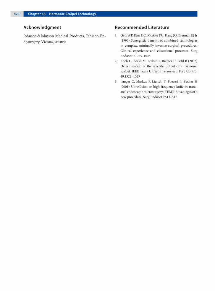
��� Chapter �� Harmonic Scalpel Technology
Recommended Literature
1. Geis WP, Kim HC, McAfee PC, Kang JG, Brennan EJ Jr (1996) Synergistic benefits of combined technologies in complex, minimally invasive surgical procedures. Clinical experience and educational processes. Surg Endosc10:1025–1028
2. Koch C, Borys M, Fedtke T, Richter U, Pohl B (2002) Determination of the acoustic output of a harmonic scalpel. IEEE Trans Ultrason Ferroelectr Freq Control 49:1522–1529
3. Langer C, Markus P, Liersch T, Fuezesi L, Becker H (2001) UltraCision or high-frequency knife in trans-anal endoscopic microsurgery (TEM)? Advantages of a new procedure. Surg Endosc15:513–517
Acknowledgment
Johnson & Johnson Medical Products, Ethicon En-dosurgery, Vienna, Austria.

69.1 Optical Port System
AutoSuture™ Visiport™ (Auto Suture, Norwalk, CT, USA) consists of a pistol-grip handle with a trigger and an opening to accommodate a 10-mm laparo-scope. When the trigger is pulled, the blade extends approximately 1 mm and immediately retracts, per-mitting tissue dissection. The 10-mm, 0° laparos-cope permits visualization as the obturator passes through the body wall. (Courtesy of Covidien Aus-tria, Brunn am Gebirge, Austria)
69.2 SurgRx™ Enseal™ Tissue Sealer
EnSeal™ (SurgRx, Redwood City, CA, USA) vessel-sealing nanopolar technology offers a high-com-pression jaw design to provide secure, rapid vessel sealing with virtually no unwanted thermal effects. It is the first and only system that controls energy deposition at the electrode–tissue interface. The patented polymer temperature control (PTC) elec-trode can control the energy delivery at the tip.
69 Instrument and Device OptionsAmulya K. Saxena

��� Chapter �� Instrument and Device Options
69.3 Locking Port with Balloon
The AutoSuture™ blunt-tip, 10-mm trocar (Auto Su-ture, Norwalk, CT, USA) has a balloon at the distal end of the sleeve that is complemented by a proxi-mal foam collar assembly to minimize leakage and secure the port to the body wall. (Courtesy of Covi-dien Austria, Brunn am Gebirge, Austria)
69.4 Pediatric Locking Port
AutoSuture™ Pediport™ Locking Trocar (Auto Su-ture, Norwalk, CT, USA) is a 5mm disposable port system with a locking mechanism. Once inserted inside the abdominal cavity, the trocar is removed and the head of the port is twisted which in turn opens an umbrella at the tip of the port. From the outside a rubber seal can be pushed to the skin which ensures a bidirectional securing of the port.
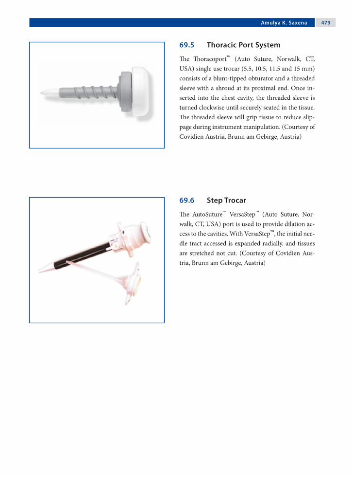
Amulya K. Saxena ���
69.5 Thoracic Port System
The Thoracoport™ (Auto Suture, Norwalk, CT, USA) single use trocar (5.5, 10.5, 11.5 and 15 mm) consists of a blunt-tipped obturator and a threaded sleeve with a shroud at its proximal end. Once in-serted into the chest cavity, the threaded sleeve is turned clockwise until securely seated in the tissue. The threaded sleeve will grip tissue to reduce slip-page during instrument manipulation. (Courtesy of Covidien Austria, Brunn am Gebirge, Austria)
69.6 Step Trocar
The AutoSuture™ VersaStep™ (Auto Suture, Nor-walk, CT, USA) port is used to provide dilation ac-cess to the cavities. With VersaStep™, the initial nee-dle tract accessed is expanded radially, and tissues are stretched not cut. (Courtesy of Covidien Aus-tria, Brunn am Gebirge, Austria)

��0 Chapter �� Instrument and Device Options
69.7 The Veroscope: Veress Needle Insertion Under Endoscopic Control
The Veroscope (Richard Wolf, Knittlingen, Ger-many) consists of: (a) a 1.9-mm 0° scope, (b) a spring-loaded 3-mm transparent tip, (c) a 3-mm Veress needle, and (d) a 3-mm port sleeve. The sys-tem is assembled a-d and introduced into the sub-cutaneous tissue. It is pushed forward under visual aid with slight pressure until the fascia and peri-toneum are opened. Once inside, insufflation is started. A 3-mm dilatation sleeve (Veroscout, see next section) is placed and the Veroscope system retracted. Using dilatation trocars, the port tract is dilated and replaced with a larger port. (Courtesy of Richard Wolf, Knittlingen, Germany)

Amulya K. Saxena ��1
69.8 Veroscout: Incision Dilatation Sleeve
The Veroscout (Richard Wolf, Knittlingen, Ger-many) is a 3-mm dilatation port sleeve that is placed in the port tract after abdominal access has been es-tablished using the Veress needle. Dilatation of the port tract and placement of a larger port is achieved by using a special “nose” dilatation trocar (inset). The trocar is inserted into a port, after which the two are introduced as a set in the Veroscout and guided as far as the abdomen. The Veroscout opens along its length and the trocar and port are inserted without any problem. (Courtesy of Richard Wolf, Knittlingen, Germany)

��2 Chapter �� Instrument and Device Options
69.9 Antifogging Agents
The active components of antifogging agents, such as Ultrastop (Sigmapharm, Vienna, Austria), form a transparent film on glass surfaces that reduces the surface tension of water to such a degree that the water molecules are unable to form droplets. (Cour-tesy of Sigmapharm Arzneimittel, Vienna, Austria)
69.10 Defogging Heated Endoscope Lens Protector
Defogging Heated Endoscope Lens Protector (DHELP®; New Wave Surgical, Rego Park, NY, USA) bathes the scope in a warm anti-fog solution until its ready for use. The combination of heat and the antifog-solution eliminates fogging for the en-tire procedure. (Courtesy of New Wave Surgical, Rego Park, NY, USA)

Amulya K. Saxena ��3
69.11 Fibrin Glue Applicator
The Duplocath™ 35 MIS (Baxter Healthcare, Deer-field, IL, USA) catheter can be passed through a 5mm port for endoscopic application of fibrin glue. The catheter works with the Duplojet™ application device. (Courtesy of Baxter Biosurgery/Bioscience Austria, Vienna, Austria)
69.12 Fibrin Spray Applicator Device
The Easy Spray™ device (Baxter Healthcare, Deer-field, IL, USA) is a compressed gas controller for spraying fibrin sealant with the appropriate spray set. (Courtesy of Baxter Biosurgery/Bioscience Aus-tria, Vienna, Austria)
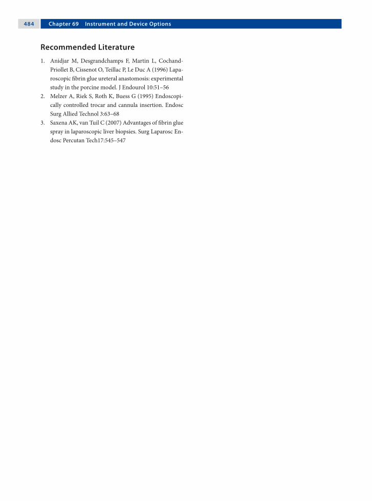
��� Chapter �� Instrument and Device Options
Recommended Literature
1. Anidjar M, Desgrandchamps F, Martin L, Cochand-Priollet B, Cissenot O, Teillac P, Le Duc A (1996) Lapa-roscopic fibrin glue ureteral anastomosis: experimental study in the porcine model. J Endourol 10:51–56
2. Melzer A, Riek S, Roth K, Buess G (1995) Endoscopi-cally controlled trocar and cannula insertion. Endosc Surg Allied Technol 3:63–68
3. Saxena AK, van Tuil C (2007) Advantages of fibrin glue spray in laparoscopic liver biopsies. Surg Laparosc En-dosc Percutan Tech17:545–547

70.1 Self-Righting Needle Holders
Smart needle holders are designed to automati-cally self-right the needle to the correct position in the holder when the jaws of the needle holder are closed (Sarbu™; Richard Wolf, Knittlingen, Ger-many). Furthermore, they have a built-in suture cutter to avoid instrument changes once the suture has been tied. (Courtesy of Richard Wolf, Knittlin-gen, Germany)
70.2 Sew-Right Sewing Device
The Sew-Right® SR•5 (LSI Solutions, Victor, NY, USA) is a reloadable 5-mm sewing device. To sew: (1) the needle is passed through tissue, (2) after which it automatically captures the suture, (3) and pulls it back through the tissue; (4) The second nee-dle can be selected to take the second bite; after which the two ends are tied.
70 Suturing Aids in Endoscopic SurgeryAmulya K. Saxena

��� Chapter �0 Suturing Aids in Endoscopic Surgery
70.3 Quik-Stitch® Suturing System
The Quik-Stitch® endoscopic suturing system (Pare Surgical, Englewood, CO, USA) is a 5-mm delivery system with a pretied Roeder knot. It consists of a 5-mm reusable, stainless-steel handle, 2.1-mm reus-able needle driver, and a patented suture spool with a straight taper point or blunt-tip needle. (Courtesy of Pare Surgical, Englewood, CO, USA)
70.4 Clip Knots for Continuous Sutures
Lapra-Ty-II™ (Ethicon, Somerville, NJ, USA) are absorbable suture clips made of polydiaxanone polymer to secure the ends of suture. A special clip applicator is necessary to secure the clip on the su-ture ends. (Courtesy of Johnson & Johnson Medical Products, Ethicon, Vienna, Austria)

Amulya K. Saxena ���
70.5 Busche Port-Site Closure Device
Port sites > 5 mm have to be closed to prevent port-site hernias, especially in adolescent bariatric sur-gery. The Busche port-site closure device (Rich-ard Wolf, Knittlingen, Germany) comprising of a guide (top) and a grasping forceps (bottom) with a sharp tip (inset) is a useful tool for port-site closure. (Courtesy of Richard Wolf, Knittlingen, Germany)

��� Chapter �0 Suturing Aids in Endoscopic Surgery
Step 2: The Forceps exit point must not be close to the defect edge to ensure full-thickness closure. The suture is released with ~4 cm length in the abdo-men. (Courtesy of Richard Wolf, Knittlingen, Ger-many)
70.5.1 Technique of Port-Site Closure with the Busche Device
Step 1: The guide is first introduced into the port site, after which the grasping forceps with suture is inserted through it. (Courtesy of Richard Wolf, Knittlingen, Germany)

Amulya K. Saxena ���
Step 3: The forceps is partially retracted into the guide. With the retracted forceps, the guide is ro-tated 180° and the forceps reintroduced in the ab-domen. (Courtesy of Richard Wolf, Knittlingen, Germany)
Step 4: The forceps grasps the suture and then is then partially retracted into the guide. The guide and the forceps are removed and the knot tied ex-tracorporeally. (Courtesy of Richard Wolf, Knittlin-gen, Germany)

��0 Chapter �0 Suturing Aids in Endoscopic Surgery
Recommended Literature
1. Bermas H, Fenoglio M, Haun W, Moore JT (2004) Laparoscopic suturing and knot tying: a comparison of standard techniques to a mechanical assist device. JSLS 8:187–189
2. Johnson WH, Fecher AM, MacMahon RL, Grant JP, Pryor AD (2006) VersaStep trocar hernia rate in un-closed fascial defects in bariatric patients. Surg Endosc 20:1584–1586
3. Sahin M, Eryilmaz R, Okan I (2006) Closure of fascial defect at trocar sites after laparoscopic surgery. Minim Invasive Ther Allied Technol 15:317–318
70.6 EndoStitch Suturing Device
The Autosuture™ EndoStitch™ (Auto Suture, Nor-walk, CT, USA) is a 10-mm, single-use suturing de-vice for intracorporeal knot tying. To create an in-tracorporeal knot at the end of the suture line, the needle is placed in the left jaw position and passed under the suture line at the end of the incision (a). The needle is toggled to the right jaw to create a loop. With the needle in the right jaw, a loop of su-ture is placed between the jaws of the EndoStitch™ (b). The needle is then toggled to the left jaw and pulled around the loop by passing under the suture on the right side (c) and tied (d). (Courtesy of Covi-dien Austria, Brunn am Gebirge, Austria)

71.1 Slip Knots
Surgical knot configuration is determined by the al-ternating or repetitive direction of rotation of se-quential throws of suture to form a knot. Once a knot is configured, it can be conformed into either a flat knot or a slip knot as it is secured.
Slip knots, also known as hitched knots, are formed when one end of suture is rotated around the other end that remains straight. The most com-mon extracorporeally tied slip knots are Roeder, Melzer, and Tayside.
71.2 Extracorporeal Slip Knot Material
Extracorporeal knots are secure if braided materials are used:1. Dacron (Ethibond™‡, Ti-Cron™† or Ethi-
flex™‡).2. Lactomer (Polysorb™†, Dexon™†, Vicryl™‡).3. Melzer and Tayside knots are resonably secure
with polydiaxone. († Syneture, Norwalk, CT, USA; ‡ Ethicon,
Somerville, NJ, USA)
It is important to note that slip knots must be pushed down. They should never be pulled up on like a lasso. The length of the suture must be at least 75 cm or more.
71 Slip Knot TechniquesAmulya K. Saxena

��2 Chapter �1 Slip Knot Techniques
Figure 71.2 Figure 71.1
71.3 Roeder Knot (Extracorporeal Knot)
Please see Figs. 1–4.
One half knot is taken first Two rounds over both the limbs

Amulya K. Saxena ��3
Figure 71.3 Figure 71.4
Second half knot on one loop Knot is stacked and pushed

��� Chapter �1 Slip Knot Techniques
71.4 Metzler Slip Knot (Extracorporeal Knot)
Please see Figs. 5–8.
Figure 71.5 Figure 71.6
Two half knots are taken first Three rounds over both limbs

Amulya K. Saxena ���
Figure 71.7 Figure 71.8
First half hitch on one loop Followed by a second half hitch

��� Chapter �1 Slip Knot Techniques
71.5 Tayside Knot (Extracorporeal Knot)
Please see Figs. 9–12.
Figure 71.9 Figure 71.10
One half knot and four half turns around the lon-ger suture limb
The tail is passed through the second and third loop

Amulya K. Saxena ���
Figure 71.11 Figure 71.12
A locking hitch is made The knot is stacked and the excess tail cut off

��� Chapter �1 Slip Knot Techniques
Recommended Literature
1. Sharp HT, Dorsey JH, Chovan JD, Holtz PM (1996) A simple modification to add strength to the Roeder knot. J Am Assoc Gynecol Laparosc 3:305–307
2. Shimi SM, Lirici M, van der Velpen G, Cuschieri A (1994) Comparative study of the holding strength of slipknots using absorbable and nonabsorbable ligature materials. Surg Endosc 8:1285–1291
3. Lo IK, Burkhart SS, Chan KC, Athnansiou K (2004) Arthroscopic knots: determining the optimal bal-ance of loop security and knot security. Arthroscopy 20:489–502
Figure 71.13
71.6 Slipping Square Knot (Intracorporeal Knot)
Please see Figs. 13 and 14.
Figure 71.14
The first and second throws are placed, but left loose
The long end is pulled and the tail pushed to slip and snug the knot

72.1 Milestones in Robotic Surgery
In 1985, the Puma 560 was the first robot in surgery that was used to place a needle for a brain biopsy using computed tomography guidance. Three years later, in 1988, the Probot was developed at Imperial College London and used to perform prostatic sur-gery. Later in 1992, the Robodoc from Integrated Surgical Systems was introduced to mill out precise fittings in the femur for hip replacement. However, robotic systems for endoscopic surgery were devel-oped in 1994 by Computer Motion (Aesop and the Zeus) and in 1997 by Intuitive Surgical (da Vinci).
72.2 Endoscopic Surgery Robotic Systems
In 2003, Computer Motion (Goleta, CA, USA) was merged with Intuitive Surgical (Sunnyvale, CA, USA). Although the da Vinci surgical system is cur-rently the only robotic system in endoscopic sur-gery being offered by Intuitive Surgical, reports with experiences on the robotic systems supplied by Computer Motion – Aesop, Zeus, and Hermes – are constantly being published.
The Aesop, Zeus, and Hermes robotics systems purchased by many medical centers in the late 1990s and early 2000s are still operational and hence de-serve to be mentioned.
72 Developments in Robotic SystemsAmulya K. Saxena

�00 Chapter �2 Developments in Robotic Systems
72.3 Aesop Robotic System
Aesop (Computer Motion) was a robot system for holding cameras in endoscopic surgery. In 1994, the Aesop-1000 system became the world’s first surgical robot certified by the US Food and Drug Administration. Computer Motion followed with Aesop-2000 in 1996, with the enhancement of voice control, and in 1998, the Aesop-3000, with seven degrees of freedom. The introduction of the Aesop-3000 provided more flexibility with regard to how surgeons and nurses could position the endoscope. By 1999, over 80,000 surgical procedures had been performed using Aesop technology. (Courtesy of Intuitive Surgical, Sunnyvale, CA, USA © 2007)

Amulya K. Saxena �01
72.4 Zeus Robotic System
The Zeus robotic system (Computer Motion) made an impact on endoscopic surgery in late 1999 and early 2000. With the Zeus system, all of the instru-ments were robotic. The surgeon could sit comfort-ably at a master console and control the slave ro-botic instruments using a pair of master manipula-tors. Laborde, in Paris, performed the first pediatric cardiac procedure using the Zeus robotic system, closure of the patent ductus arteriosus. (Courtesy of Intuitive Surgical, Sunnyvale, CA, USA © 2007)
72.4.1 Zeus Robot Arms
Set up of the Zeus robotic system showing the placement of the robotic arms on the operation table. (Courtesy of Intuitive Surgical, Sunnyvale, CA, USA © 2007)

�02 Chapter �2 Developments in Robotic Systems
Recommended Literature
1. Klein MD, Langenburg SE, Kabeer M, Lorincz A, Knight CG (2007) Pediatric robotic surgery: lessons from a clinical experience. J Laparoendosc Adv Surg Tech A 17:265–271
2. Nguan C, Kwan K, Al Omar M, Beasley KA, Luke PP (2007) Robotic pyeloplasty: experience with three ro-botic platforms. Can J Urol 14:3571–3576
3. Panait L, Rafiq L, Mohammed A, Mora F, Merell R (2007) Robotic assistant for laparoscopy. J Laparoen-dosc Adv Surg Tech A 16:88–93
72.5 Hermes Platform
The Hermes (Computer Motion) platform was de-veloped in 1998 for centralizing the control of de-vices (using voice command or a handheld pen-dant) inside or outside the operating room. It of-fered the concept of an “intelligent operating room.” (Courtesy of Intuitive Surgical, Sunnyvale, CA, USA © 2007)

73.1 Integrated Operation Room Concept
The aim of integrated operation rooms is to provide the ideal room layout for performing minimally in-vasive and conventional procedures. Customized to specific fields, these operating rooms have solutions to offer the best possible ergonomics to the surgeon and the team along with direct interactive control of the equipment.
Integrated operation suites provide intuitive control of all functions of the equipments via re-mote control, touch screen and/or speech control – fast, easy, and safe, directly from the sterile area.
73.2 Advantages
There are many advantages of integrated operation suites:1. Improved operation room layout.2. Integration of endoscopic equipment.3. Direct device control from sterile area.4. Freedom of device setting.5. Improved efficiency in device control.6. Shorter set-up and change-over times.7. Integration of existing systems.8. Cost reduction by optimal workflow.9. Better ergonomics for the team.10.Concentration of equipment.
73 Concept of the Integrated Endoscopic Operation RoomAmulya K. Saxena

�0� Chapter �3 Concept of the Integrated Endoscopic Operation Room
73.3 Ergonomics of an Integrated Endoscopic Surgery Room
Integrated endoscopic surgery rooms allow the set up of surgical equipments without overcrowding with mobile carts and cables. The risk of tripping over a thicket of cables is eliminated by one central cable outing for the power supply, carbon dioxide, compressed air, vacuum, and video signals. Sus-pended flat-screen monitors overcome the problem of positioning endoscopic carts toward the head of the patient (an area occupied by the anesthetist and ventilator) and provide the surgical team with the desired angle and line of vision. (Courtesy of Rich-ard Wolf, Knittlingen, Germany)

Amulya K. Saxena �0�
73.4 Voice-/Remote-Control Option
The designations of the device functions on the screen are simply spoken clearly by the operator for voice-controlled operation. Otherwise, the auto-clavable remote (inset) provides direct control from the sterile area. (Courtesy of Richard Wolf, Knitt-lingen, Germany)
73.5 Nurse Station: Touch-Screen Control
The touch-screen nurse station allows centralized device control for personnel. (Courtesy of Richard Wolf, Knittlingen, Germany)

�0� Chapter �3 Concept of the Integrated Endoscopic Operation Room
73.6 Centralized Equipment Control
All devices (from the operation table and operation lamp to the endoscopic surgery equipment) to be controlled in the network appear on the monitor as a simple intuitive guided menu. (Courtesy of Rich-ard Wolf, Knittlingen, Germany)
73.7 Image Management System
This feature provides the ability to combine images and reports from all medical disciplines. It allows image acquisition, processing, and archiving to a server or recording device. (Courtesy of Richard Wolf, Knittlingen, Germany)
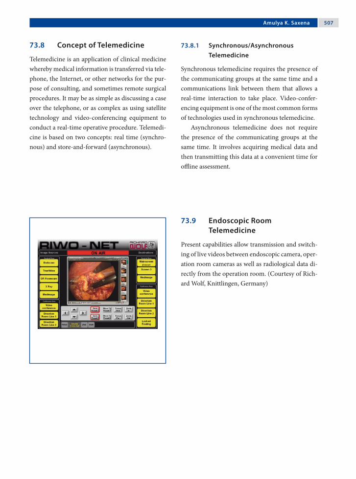
Amulya K. Saxena �0�
73.8 Concept of Telemedicine
Telemedicine is an application of clinical medicine whereby medical information is transferred via tele-phone, the Internet, or other networks for the pur-pose of consulting, and sometimes remote surgical procedures. It may be as simple as discussing a case over the telephone, or as complex as using satellite technology and video-conferencing equipment to conduct a real-time operative procedure. Telemedi-cine is based on two concepts: real time (synchro-nous) and store-and-forward (asynchronous).
73.8.1 Synchronous/Asynchronous Telemedicine
Synchronous telemedicine requires the presence of the communicating groups at the same time and a communications link between them that allows a real-time interaction to take place. Video-confer-encing equipment is one of the most common forms of technologies used in synchronous telemedicine.
Asynchronous telemedicine does not require the presence of the communicating groups at the same time. It involves acquiring medical data and then transmitting this data at a convenient time for offline assessment.
73.9 Endoscopic Room Telemedicine
Present capabilities allow transmission and switch-ing of live videos between endoscopic camera, oper-ation room cameras as well as radiological data di-rectly from the operation room. (Courtesy of Rich-ard Wolf, Knittlingen, Germany)

�0� Chapter �3 Concept of the Integrated Endoscopic Operation Room
Recommended Literature
1. Gallagher AG, Smith CD (2003) From the operating room of the present to the operating room of the fu-ture. Human-factors lessons learned from the min-imally invasive surgery revolution. Semin Laparosc Surg 10:127–139
2. Kenyon TA, Urbach DR, Speer JB, Waterman-Hukari B, Foraker GF, Hansen PD, Swanstrom LL (2001) Dedi-cated minimally invasive surgery suites increase oper-ating room efficiency. Surg Endosc 15:1140–1143
3. Marohn MR, Hanley EJ (2004) Twenty-first century surgery using twenty-first century technology: surgical robotics. Curr Surg 61:466–473
73.10 Video Conferencing
Video conference services offer the establishment of a direct “dial” access link from the operation room. It may either be a direct two-way communication or multipoint exchange. (Courtesy of Richard Wolf, Knittlingen, Germany)

74.1 Why is Virtual Reality Required?
74.1.1 Implant Basic Skills
Virtual reality simulators focus on implanting and complementing basic skills that would be needed by the trainee toward performing a bigger procedure.
74.1.2 Evaluate Skills
The simulators allow the objective evaluation of surgical skills in practice sessions that can vary in graphic complexity as well as level of difficulty, and can pose challenges to even well-versed surgeons.
Similar to flight simulators, endoscopic virtual reality simulators such as LapSim® (Surgical Sci-ence Sweden, Göteborg, Sweden) shown here are employed in the training of operative skills in endo-scopic surgery. (Courtesy of Surgical Science Swe-den, Göteborg, Sweden)
74 Virtual RealityAmulya K. Saxena
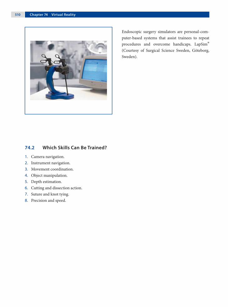
�10 Chapter �� Virtual Reality
Endoscopic surgery simulators are personal-com-puter-based systems that assist trainees to repeat procedures and overcome handicaps. LapSim® (Courtesy of Surgical Science Sweden, Göteborg, Sweden).
74.2 Which Skills Can Be Trained?
1. Camera navigation.2. Instrument navigation.3. Movement coordination.4. Object manipulation.5. Depth estimation.6. Cutting and dissection action.7. Suture and knot tying.8. Precision and speed.

Amulya K. Saxena �11
74.2.1 Camera Navigation
Simulators enable trainees to subconsciously realize and accept correct scope positions.
74.2.2 Instrument Navigation
Precision in instrument navigation and synchron-ization is important in endoscopic surgery proce-dures.
74.2.3 Coordination
This involves three aspects:1. Hand–eye (virtual coordination).2. Hand–hand (handling coordination).3. Image-anticipation (cameraman and surgeon
coordination).
74.2.4 Object Manipulation
Object manipulations helps to differentiate grasp-ing forces from shear forces. It also helps in the esti-mation of the freedom of movement.
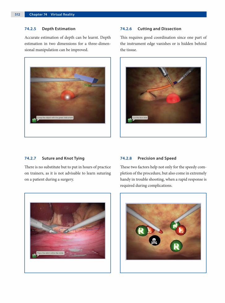
�12 Chapter �� Virtual Reality
74.2.5 Depth Estimation
Accurate estimation of depth can be learnt. Depth estimation in two dimensions for a three-dimen-sional manipulation can be improved.
74.2.6 Cutting and Dissection
This requires good coordination since one part of the instrument edge vanishes or is hidden behind the tissue.
74.2.7 Suture and Knot Tying
There is no substitute but to put in hours of practice on trainers, as it is not advisable to learn suturing on a patient during a surgery.
74.2.8 Precision and Speed
These two factors help not only for the speedy com-pletion of the procedure, but also come in extremely handy in trouble shooting, when a rapid response is required during complications.

Amulya K. Saxena �13
74.3 Procedures that Can Be Simulated on LapSim
74.3.1 Cholecystectomy
This exercise simulates the critical steps during a laparoscopic cholecystectomy procedure. In the first part, the cystic duct and artery are clipped and dissected. In the second part, the gall bladder is sep-arated and removed from the liver.
74.3.2 Intestinal Handling
The objective in this training exercise is to measure a predetermined length of the upper intestine using a suction device with markings of one centimeter in width for orientation. The camera is controlled by the computer and the instruments consists of two graspers.
74.3.3 Myoma Suturing
This training task has the highest level of difficulty in the Gynecology package, requiring the trainee to suture and close the uterine wall cavity caused by a myectomy. The procedure is performed using two graspers, needle and thread.
74.3.4 Salpingectomy
This exercise involves rinsing and suction of a bleeding ectopic pregnancy. After control of bleed-ing, the ectopic pregnancy has to be cut free from the Fallopian tube using bipolar graspers and/or clip applicators and diathermic scissors. The task ends by placing the ectopic pregnancy in the endo-scopic basket.

�1� Chapter �� Virtual Reality
Recommended Literature
1. Aggarwal R, Grantcharov TP, Eriksen JR, Blirup D, Kristiansen V, Funch-Jensen P, Darzi A (2006) An evi-dence-based virtual reality training program for nov-ice laparoscopic surgeons. Ann Surg 244:310–314
2. Cosman PH, Hugh HJ, Shearer CJ, Merrett ND, Bian-kin AV, Cartmill JA (2007) Skills acquired on virtual reality laparoscopic simulators transfer into the oper-ating room in a blinded, randomised, controlled trial. Stud Health Technol Inform 125:76–81
3. van Dongen KW, Tournoij E, van der Zee DC, Schij-ven MP, Broeders IAMJ (2007) Construct validity of the LapSim: can the LapSim virtual reality simulator distinguish between novices and experts? Surg Endosc 21:1413–1417
Acknowledgment
Surgical Science Sweden, Göteborg, Sweden.

anesthesia 63inhalation 63intravenous 63
angiocath 325anterior discectomy 161, 163anterior gastrotomy 345anterior spine procedure 78antibiotic 131
cefuroxime 171, 291, 307gentamicin 411metronidazole 261penicillin 357
antifogging agent 68, 482DHELP® 482Ultrastop 482
Antoine Jean Desormeaux 5aorta adventitial layer 145, 148aortic adventitial layer 145aortopexy 78, 143aperture (rod lens) 12appendectomy 13, 182, 247
right-iliac-fossa 255single-port 249, 255
appendiceal mass 181, 182appendicitis
acute 249coprolith 249impacted stool 255mesoceliac 249nonperforated 255perforated 249phlegmonous 255retrocecal 249, 255
––
––––
––
––
––––––––
Aabdomen visualization 9abdominal adhesion 299abdominal cavity 8abdominal musculature 387abdominal pain 181
acute 181chronic 181recurrent 181
abdominal wall vessel injury 451deep inferior epigastric artery 451
access 71closed 71open 71, 74
activate electrode 444adjuvant therapy 119Adolph Kussmaul 6adrenalectomy 397
bilateral 399retroperitoneal approach 399
adrenal gland 399adrenal incidentaloma 399adrenal metastasis 399adrenal tumor 399adrenal vein 399, 400Advocat cannula 339air embolism 85air leak (port site) 113albendazole 339Alfred Fiedler 8alveolar collapse 60anaphylactic reaction 339anastomosis 23, 24
–––
–
––
––
Subject Index

�1� Subject Index
appendixfriable 255
argon beam coagulator 101argon laser 456
polycystic ovarian disease 456retina injury 458
arrhythmia 157arterial catheter 333arthroscopy 10arthroscopy knife
pyloromyotomy 222aspiration-irrigation system 35aspiration pneumonia 189, 195, 211, 231atherosclerosis 61atraumatic grasping forcep 181atretic biliary tree 327atretic cystic duct 326atretic gallbladder 326atropine 64audible explosion 11autoclavable remote 25autologous bone graft 163automatic laparoscope manipulators 25azygos vein 125
BBabcock forcep 180, 270balloon catheter
retroperitoneal space 416balloon dilatator 418barium swallow 231benign liver tumor 333Bertram Moses Bernheim 9Betadine 74betadine swab 255bile leakage 339biliary atresia 184, 330biliary tract 319biopsy
frozen section 276lung 78
–
––
–
–
––
lymph node 78mediastinal tumor 78
bipolar electrocauteryneuroblastoma 118
bipolar electrocautery forcepFowler-Stephens in Prune-Belly syndrome 386
bipolar forcepappendectomy 248
biportal procedure 157bleb. see pulmonary blebbleeding disorders 181blood group 181blood loss assessment 63blood pressure monitoring 64body mass index 217bone chip 165bone marrow aspirates 119bone scan 119bougie 189, 190, 191, 195bowel injury 183, 451
thermal 452bowel obstruction 307brachial plexus 157brachial plexus injury 452bradycardia 145bronchial blocker 80bronchiectasis 95bronchogenic cyst 78, 101, 102
hemorrhage 101infection 101
bronchogenic cyst resection 99bronchoscopy 80, 95, 145, 148bronchus
clip 97stapler 97suture 97
bulb (light source) 8halogen 33xenon 33
bupivacaine 65button (instrument) 50
––
–
–
–
–
––
–––
––

Subject Index �1�
Ccachexia 201calcium stimulation test 351Calot’s triangle 307, 308capacitive coupling 446capnography 64carbon dioxide 34
cardiac arrhythmia 451end-tidal 63
carbon dioxide laser 456corneal burn 458endometriosis 456
carbon filament 7carbonic acid 451carbon monoxide 61cardiac arrhythmia 61cardiac fibrillation 85cardiac output 62cardiac volume 60cardiomegaly 139cardiomyotomy 211cardiorespiratory dysfunction 333cartilage remnant 102catheter 65
epidural 65Fogarty 80intrapleural 65suprapubic 423Swan-Ganz 80transurethral 423
celioscopy 8, 12centralized equipment control 506central nervous system malformation 299central venous line 333central venous pressure 333charge coupled device (CCD) camera 32
single-chip 32three-chip 32
chemical defogger 68chemical pleurodesis 113
––
––
––––––
––
chest filmpectus excavatum 171
chip (video camera) 32cholangiogram 320cholangiogram needle 180cholangiography 184, 185, 307, 325, 351cholangitis 307, 319cholecystectomy 14, 305, 319, 321cholecystitis 307
acute 307choledochal cyst 317, 319, 320choledochal remnant 327choledochocele 319choledocholithiasis 307cholelithiasis 307cholinesterase inhibitor 139chronic constipation 261, 291chylous leak 153ciliated epithelium 102circular end-to-end anastomosis (EEA) stapler
colectomy 266cis-atracuronium 63clip 23. see also titanium clipclip knot 486CO₂ 61, 62, 65coagulate waveform 26coagulation 26coagulation disorder 405coagulopathy 333, 399coaptive coagulation 444coaxial working channel 237Cohen’s procedure 423colectomy 265collagen seal 28colon biopsy 181, 259
extramucosal 261, 276full-thickness biopsy 261laparoscopic-assisted biopsy 261
color doppler ultrasoundovarian torsion 393splenic torsion 365
–
–
–
–––
––

�1� Subject Index
colosplenic ligament 358colostomy 283
loop 283combustion 61, 63, 113common hepatic duct 321compensatory sweating 157complication 449
thromboembolic 61computed tomography
dual-phase 345hydatid cyst 340neuroblastoma 119pancreatectomy 351pancreatic-imaging protocol 345pulmonary sequestration 107sympathectomy 157thoracic neuroblastoma 120tracheal compression 145
congenital adenomatoid malformation 95congenital diaphragmatic hernia 15, 78, 129, 131
chest film 135Gore-Tex® 130Gore-Tex® patch 134incarcerated 131incarcerated delayed 131intestine herniation 133kidney herniation 132sac 132, 133, 134spleen herniation 132
congenital heart defects 151contact desiccation 444contrast medium 101conversion 67costovertebral junction 158cotton swabs
patent ductus arteriosus 150Credé’s maneuver 189, 283Crohn’s disease 267culture test tube 338
–
–
–––––––––
–––––––––
–
cutaneous femoral lateral nerve 437cut waveform 26cyanosis 145cystic artery 14, 307, 308, 320cystic duct 14, 307, 308, 320cystic fibrosis 95, 291, 379cystojejunostomy 345cystoscope 428cystoscopy 423, 424cystoscopy set 422cytokine 60
Ddata storage 37da Vinci robot 87
endoscope 87DeBakey grasper 417decortication 78Deflux™ 428, 430
dextranomer/hyaluronic acid copolymer 429microsphere 429sodium hyaluronan 429
degree of movement 48dentate line 278Deschamp’s needle 174desiccation 26diagnostic laparoscopy 179diamond-shape stitches 231, 232diaphragm 63, 108
left crus 190posterior flap 133right crus 190
diaphragmatic irritation 62diaphragm trauma 78diathesis 313digital video disc 36digital video printer 36digital video recorder 36direct coupling 446
–
–––
–––
Subject Index �1�
discectomy 164dissection hook
patent ductus arteriosus 150Dor fundoplication 211, 213double-barrel hepaticojejunostomy 319double-J ureteral stent 417, 420
guidewire 420double-lumen intubation
anterior discectomy 163hemivertebrectomy 163
dual-puncture technique 10Duhamel-Martin procedure 273, 275dumbell formation 308duodenojejunal junction 181duplication cyst 181dying spell 145dysmotility disorder 261dysphagia 201, 211dysrythmia 65
Eechinococcus cyst 339
calcification 339multivesicular 339
Edison’s light bulb 8elastin seal 28electrical circuit 27electricity 6electrocardiogram 63electrocardiography 64electrocoagulation 211electrode 26, 27, 33, 445
hooked-shaped 26electrode pad 26electrolyte abnormalities. 223electrosurgery 18, 26
bipolar 27coagulation waveform 443cut waveform 443monopolar 26, 27
–
–
––
––
–
––––
embolusvenous gas 64
EMLA cream 63emotional instability 217empyema 81, 157empyemectomy 78endocarditis 151Endo GIA stapler 279, 313
colectomy 266Duhamel-Martin procedure 274pancreatic pseudocyst 344pulmonary bleb 112
endoscope 5, 6endoscopic clip
pulmonary sequestration 106endoscopic clip applicator 23
cholecystectomy 306Fowler-Stephens in Prune-Belly 386lobectomy 94nephroureterectomy 404patent ductus arteriosus 150thymectomy 138undescended testis 378varicocele ligation 436
endoscopic fan retractor 162endoscopic linear stapler 23
pulmonary bleb 113endoscopic liver retractor
adrenalectomy 398Nissen fundoplication 194Toupet fundoplication 200
endoscopic loop sutureappendectomy 248intussusception 242Meckel’s diverticulum 236
endoscopic retractor 20fan 79snake 79
endoscopic retrograde cholangiopancreatography 307
–
––––
–
––––––––
–
–––
–––
––

�20 Subject Index
endoscopic stapler 114lobectomy 94Meckel’s diverticulum 236pulmonary sequestration 106
endoscopic submucosal injection 423endoscopic surgery tower 38endoscopic suturing 51endoscopic ultrasound 83EndoStitch™ 490endotracheal tube
balloon 80double-lumen 157dual-lumen 80
EndoWrist® 88EnSeal™ 477
nanopolar technology 477Nissen fundoplication 194polymer temperature control (PTC) 477splenectomy 356
enterostomy 275epidural bleeding 167epidural catheter 417ergonomic 41, 43, 47
dual-monitor option 45single-monitor option 44
Erich Mühe 14eschar 26, 444esophageal achalasia 209, 211esophageal atresia 123, 125
distal fistula 126, 127H-type fistula 125long gap 125proximal pouch 126, 127
esophageal dysmotility 145, 201esophageal hiatus 190esophageal mucosa 211esophageal peptic stricture 201esophageal retractor 188esophageal stricture 145esophagitis 195
–––
–––
––––
––
––––
esophagogastric junction 211esophagoscopy 6esophagus
atresia 78dissection 78myotomy 78tumor 78
evoked potentialmotor 163somatosensory 163
external sphincter muscle complex 287extralobar sequestration 107extraperitoneal emphysema
port 450veress needle 450
eyepiece scratches 34
Ffailed myotomy 211failure to thrive 189, 195falciform ligament 319, 334familial adenomatous polyposis 267fatigue 47femoral hernia 373, 375fetal surgery 15Fetendo clip 15fetoscopic technique 15fiber-optic cable 33fiber optic 28fibrin glue 112, 113
Duplocath™ 483Duplojet™ 483partial splenectomy 360pulmonary bleb 114spray applicator 483
flank instrument 358flashlight 11flat screen panel 44fluid resuscitation 223fluoroscopy 80, 166
––––
––
––
–––––
Subject Index �21
fogging 68forcep 20
biopsy 20spike biopsy 20spoon 20
foreign body 453clip 453sapphire laser tip 453staples 453
Fowler-Stephens in Prune-Belly syndrome 385Fowler-Stephens procedure 381
peritoneal strip 389frame-stitch 201, 203fulguration 444
spray 444fundus wrap 202
Ggallstone pancreatitis 307ganglioneuromatosis 261gas delivery system 59gas embolism 451
cardiac puncture 451gas leak 75gastophrenic ligament 22gastric band 22gastric banding 215
pars flaccida technique 217perigastric technique 217two-step technique 217
gastric emptying 201, 231gastric pouch 219gastroesophageal reflux 145, 189, 195, 201, 217,
231gastrohepatic ligament 190gastrointestinal tract injury 450
bilious discharge 450fecal soilin 450
gastrosplenic ligament 358, 365gastrostomy 231
–––
–––
–
–
–
–––
––
gastrostomy button 195Gaucher’s disease 360general anesthesia 181generator 26
amperage 443voltage 443wattage 443
Georg Kelling 8Gerota’s fascia 418Giulio Cesare Aranzi 3glandular diseases 217Goldfinger® dissector 22, 216, 218Gore-Tex® 130grasper 18grip 49
power 49precision 49
groin hernia 373grounding pad 68growth cartilages 166growth plate 164, 166gubernaculum 379gynecology 13, 14Gyrus bipolar Trisector® 410
Hhamartoma 360handle design 49handle grip 21
axial 21handle grip diameter 50hanging-drop test 72Hans Christian Jacobaeus 9haptic 88hard drives 37harmonic scalpel 27, 467
adrenalectomy 398bronchogenic cyst 101bronchogenic cyst resection 100cavitation 474
–––
––
–
––––

�22 Subject Index
cholecystectomy 306coagulation 474coaptation 474cutting 474esophageal achalasia 210grip force 475liver resection 332splenectomy 356thymectomy 138tissue tension 475Toupet fundoplication 200
Harold Horace Hopkins 12Harrith Hasson 13Hasson cannula 217Heinz Kalk 10Heller myotomy 212Heller procedure 201hemivertebra 163, 166hemivertebrectomy 161, 163hemoclips 14hemoglobin
carboxyhemoglobin 61methemoglobin 61oxyhemoglobin 61
hemostasis 27hemostatic agent 162hemostatic gauze 165hemostatic sheet 167hemothorax 78hepatic artery 325, 327hepatic cirrhosis 307hepatic clamping 313hepatic duct 307hepatic function 339hepatic injury 451hepatitis
chronic 313hepatoduodenal ligament 334hepatogastric ligament 205hereditary spherocytosis 357hernia sac 373
–––––––––––
–––
–
hiatal dissection 201hiatal hernia 211, 217high-speed bur 162, 167high imperforate anus 281, 283Hirschsprung’s disease 181, 261, 275hook cautery
bronchogenic cyst 101Hopkins rod lens 29Horner’s syndrome 119, 157hospital stay 67human chorionic gonadotrophin (hCG) test 379Hunter grasper 242hydatid cyst 337
germinal layer 341hydatid dissemination 339hydrocephalus 299hydrogel 114hydronephrosis 412hypercapnia 62hypercarbia 65hyperhidrosis 157
axillary 157palmar 157
hyperinsulinism 351hypertension 65hypertrophic pyloric stenosis 223hypochondriac region 205hypotension 181hypothermia 60hypoxia 65, 145, 181
Iileal pouch 269ileostomy 266
end 268loop 267, 271
illumination 6, 7overhead 43
immune thrombocytopenic purpura 357immunocompromised patient 139immunologic response 60
–
–
––
––
–

Subject Index �23
immunosuppressed patient 139impalpable testes 181impregnanted silicone shunt
clindamycin 299rifampicin 299
incandescent lamp 7incarceration (bowel) 239indomethacin 151infarcted intestine 243inferior pulmonary ligament 96inferior vena cava 63inflammation 299inflammatory bowel disease 261inguinal hernia 371, 373
Incarcerated 373subcutaneous endoscopically assisted ligation (SEAL) 373
inguinal sac 374injury
tissue 48innominate artery 145, 146innominate vein 140instrument
tip 35instrument cluttering 48instrument insulation 68, 444
failure 444, 445neuromuscular stimulation 445
insufflation device 13insufflation flow rate 59insufflation pressure 60
adolescent 60children 60infant 60
insufflator 34insulinoma 351integrated operation room 503
advantage 503ergonomics 504image management 506nurse station 505
––
––
–
–
––
–––
––––
remote control 505touch screen 505voice control 505
intercostal muscle 173intercostal neuralgia 157internal inguinal ring 373, 381, 438internal spermatic vessels 388International Neuroblastoma Staging System 119intersex 181intestinal anastomosis 325intestinal atresia 181intestinal obstruction 181intra-abdominal pressure 63intracorporeal suturing 107intrahepatic vascular structure 334intralobar sequestration 107intraoperative endoscopy 211intraventricular hemorrhage 299intussusception 241, 244
contrast enema reduction 243enlarged lymph node 244hemorrhage 244incompletely reduced 243lead point 245nonreduced 243recurrent 243suspected 243
isosulfan bluelymphatic vessels 437subdartos injection 437
JJ-tipped guide wire 299J-VAC drainage tube 182Jackson-Pratt drain 341János Veres 11jejunal loop 232jejunojejunostomy 319jejunostomy 229, 231
feeding tube 230, 231, 232, 233Jewel-Thompson effect 59
–––
––––––––
––
–

�2� Subject Index
Johannes Freiherr von Mikulicz-Radecki 8John Carroll Ruddock 11Joseph Leiter 7juvenile polyp 291
Kkaryotype 379Kasai procedure 323kerosene lamp 6kidney
dysplastic 406nonfunctional 405, 411pelvis 406refluxive 405
kidney rest 81kidney stones 417knot
Aberdeen termination 55Dundee jamming 55extracorporeal 53, 54, 329hitch 53intracorporeal 53, 55, 56, 57, 201Meltzer 53Roeder knot 25, 53, 329slip 53square 55surgeon’s 55Tayside 53tumble square 55
knot-pusher 21, 54, 55modular 21
knot tying 48, 53KTP laser 456
retina injury 458Kuntz nerve 159Kurt Karl Stephan Semm 13kyphoscoliosis 231
––––
––––––––––––
–
–
Llaparoscopic stapled wedge biopsy 313laparoscopic ultrasound 307, 313, 334
liver resection 332laparoscopy 14laparothoracoscopy 9LapSim® 39, 509
cholecystectomy 513intestinal handling 513myoma suturing 513salpingectomy 513
laser 28, 69, 455absorption 455accidental activation injury 458argon 28, 455bowel injury 459carbon dioxide 455coagulation 457contact 457cutting 457dispersion 455effect 455eye injury 458human error 458ignition injury 458neodium:yttrium aluminum garnet Nd:YAG 455neodymium-doped yttrium-aluminum-garnet 28noncontact 457penetration 457plume 69potassium-titanyl-phosphate 28potassium titanyl phosphate (KTP) 455pulmonary bleb 112redirection injury 458reflection 455transmission 455ureteral injury 459wavelength 455
–
––––
––––––––––––––
–
–––––––––––
Subject Index �2�
laxative 261left laryngeal nerve monitoring 151lens
objective 29ocular 29rod 29
lesser omentum 218, 334Lichtleiter 4, 5lidocaine 65lienophrenic ligament 400life-threatening apnea 145ligament of Treitz 320LigaSure™ 28, 461
adrenalectomy 398Atlas sealer/divider 464bronchogenic cyst 101bronchogenic cyst resection 100colectomy 266foot pedal 464ForceTriad™ 465Fowler-Stephens in Prune-Belly 386gastric banding 216generator 463hydatid cyst 338Instant Response™ technology 461lobectomy 94nephroureterectomy 404neuroblastoma 118Nissen fundoplication 194pancreatectomy 350pulmonary bleb 112thermal spread 465thermography 465TissueFect™ 465Toupet fundoplication 200vessel seal histology 462V Lap 463V sealer/divider 464
light-source generator 32light bulb 7
–––
–––––––––––––––––––––––––
light source 5halogen 32xenon 32
line of vision 42liver-function test 345liver biopsy 311liver cirrhosis 313, 405liver herniation 131liver resection 331
hand-assisted laparoscopic 333total laparoscopic 333
liver retractorthree-finger 189
Lloyd-Davis position 332lobar emphysema 95lobectomy 78, 93, 107Louis Beneche 7low sperm count 437lung collapse 95lung retraction 151
MMAG3 renography 411magnetic resonance angiography (MRA) 107magnetic resonance
cholangiopancreatography 345magnetic resonance image
pancreatectomy 351sympathectomy 157tracheal compression 145, 146
malignancy 95malignant tumor 181malnourishment 267manufacturers (instruments) 47Maryland dissector 223Maximillian Carl-Friedrich Nitze 7McCarthy cystoscope 11mechanical camera holder 423mechanical compression 60mechanical ventilation
thoracic neuroblastoma 119
––
––
–
–––
–

�2� Subject Index
Meckel’s diverticulum 181, 235, 25510-mm operating scope technique 2375-mm optic port technique 237laparoscopy-assisted 237Pure laparoscopic resection 237
Meckel scan 236mediastinal cysts 101mediastinal emphysema 449megaureter 423meniscal lesion 10mental retardation 217mesenteric cyst 181mesoappendix 249, 250mesoappendix hemostasis 249mesothelial cell 60meta-iodobenzylguanidine scintigraphy 119methemoglobinemia 61Michael Harrison 15microcirculatory disturbance 61MicroMyst™ applicator 115midazolam 63minute ventilation 62, 65monitor 37, 44, 46, 68
flat-panel screen 37monopolar coagulation injury 452monopolar electrosurgery 443
alternating electrical current 443guidelines 447
monopolar hook cautery 156, 190sympathectomy 156Toupet fundoplication 200
morbidly obese 217Morgagni hernia 82mucosal perforation 211mucosectomy 101multicystic renal dysplasia 405multifunctionality handle 50muscle electrostimulator 283, 287muscle paralysis 63muscle relaxant 63
––––
–
––
––
musculoskeletal deformities 232musculoskeletal malformation 195myasthenia gravis 139
neonatal type 139
Nnasogastric tube 64
double-lumen 211Nd:YAG laser 456
pulmonary bleb 113, 114retina injury 458sapphire tip 456sculpted fibers 456
necrotizing pneumonia 95needle 51
flattened 51half-circle 51, 56ski-shape 51, 52spinal 345Veress needle 18, 64, 71
needle holder 21, 49aortopexy 144Sarbu™ 485self-righting 485smart 485
neonatal intensive care unit 151nephroureterectomy 403nerve hooks
patent ductus arteriosus 150neuroblastoma 117, 120
medullar root 119, 121neural foramen 121short intercostal vessel 120
neurogenic tumor 78, 119neurologically impaired children 231neuromuscular stimulation 26Neuronal intestinal dysplasia 261Nissen fundoplication 193, 197nitrous oxide 63, 201Nitze-Leiter cystoscope 7, 8
–
–
––––
–––––
––––
–
–––

Subject Index �2�
nonhealed umbilical stump 223nonpalpable testis
bilateral 379unilateral 379
nonsteroidal anti-inflammatory drug 65normocapnia 62normothermia 151nuclear medicine scan 351
Oobese patient 255office endoscopy 37omental hernia 452omental patch 339omentum incarceration 375oophoropexy 393, 395open-access technique 387operating scope
Meckel’s diverticulum 236single-port 31single-port appendectomy 254sympathectomy 156
operation room setup 67adrenalectomy 397anterior discectomy 161aortopexy 143appendectomy 247bronchogenic cyst resection 99cholecystectomy 305choledochal cyst 317colectomy 265colon biopsy 259congenital diaphragmatic hernia 129diagnostic laparoscopy 179Duhamel-Martin procedure 273esophageal achalasia 209esophageal atresia 123Fowler-Stephens in Prune-Belly syndrome 385gastric banding 215hemivertebrectomy 161
––
––––
–––––––––––––––––
high imperforate anus 281perineal Step 286
hydatid cyst 337inguinal hernia 371intussusception 241jejunostomy 229Kasai procedure 323liver biopsy 311liver resection 331lobectomy 93Meckel’s diverticulum 235nephroureterectomy 403neuroblastoma 117Nissen fundoplication 193ovarian cysts 391pancreatectomy 349pancreatic pseudocyst 343patent ductus arteriosus 149pectus excavatum 169pulmonary bleb 111pulmonary sequestration 105pyloromyotomy 221rectopexy 289robot-assisted pyeloplasty 415single-port appendectomy 253splenectomy 355STING procedure 427sympathectomy 155Thal fundoplication 187thymectomy 137Toupet fundoplication 199transabdominal pyeloplasty 409undescended testis 377ureter reimplantation 421varicocele ligation 435ventriculoperitoneal shunt 297wandering spleen 363
operative laparoscopy 10opioids 65
––
–––––––––––––––––––––––––––––––––––

�2� Subject Index
orchidopexy 379, 381, 437conventional 380laparoscopic 380
orchiectomy 379organoscopy-cystoscopy 9organ perfusion 61orthopedic endoscopic instrument
curette 162elevator 162forcep 162osteotome 162rongeurs 162
ovarian abscess 393ovarian artery 393ovarian cyst 391, 393
hemorrhagic 394torsion 393
ovarian cystectomy 393laparoscopically assisted extracorporeal 393laparoscopically assisted transumbilical 393
ovarian enlargement 393ovarian malignancy 393ovarian torsion 394oxygen 61oxygen saturation
postductal 131preductal 131
Ppadded safety belt 217pain
shoulder 62pancreas
uncinate process 353pancreatectomy 349pancreatic pseudocyst 343
anterior gastrotomy 346cystojejunostomy 345gastrocolic omentum location 345necrosectomy 347
––
–––––
––
––
––
–
–
––––
pancreatic necrosis 345paracolic gutter location 345pseudocystojejunal anastomosis 345summit stitch 346
pancreatic stump 353pancreatic tumor 351pancreatitis 345paradoxical port movement 47paraesophageal lesions 101partial splenectomy
lower 360upper 360
patent bile duct 329patent ductus arteriosus 78, 149, 151, 501patient positioning
adrenalectomy 398anterior discectomy 162aortopexy 144appendectomy 248bronchogenic cyst resection 100cholecystectomy 306choledochal cyst resection 318colectomy 266colon biopsy 260congenital diaphragmatic hernia 130diagnostic laparoscopy 180Duhamel-Martin procedure 274esophageal achalasia 210esophageal atresia 124Fowler-Stephens in Prune-Belly syndrome 386gastric banding 216hemivertebrectomy 162high imperforate anus 282
perineal step 286hydatid cyst 338inguinal hernia 372intussusception 242jejunostomy 230Kasai procedure 324liver biopsy 312
––––
––
––––––––––––––––––
–––––––

Subject Index �2�
liver resection 332lobectomy 94Meckel’s diverticulum 236nephroureterectomy 404neuroblastoma 118Nissen fundoplication 194ovarian cysts 392pancreatectomy 350pancreatic pseudocyst 344patent ductus arteriosus 150pectus excavatum 170pulmonary bleb 112pulmonary sequestration 106pyloromyotomy 222rectopexy 290robot-assisted pyeloplasty 416single-port appendectomy 254splenectomy 356STING procedure 428sympathectomy 156Thal fundoplication 188thymectomy 138Toupet fundoplication 200transabdominal pyeloplasty 410undescended testis 378ureter reimplantation 422varicocele ligation 436ventriculoperitoneal shunt 298wandering spleen 364
patient preparation 68patient safety concern 68pectus bar 170, 171, 172, 173, 174pectus bar bender 170pectus bar flipper 170pectus bar stabilizer plate 170pectus carinatum 171pectus excavatum 169, 171
diaphragm injury 171liver injury 171
pectus flexible template 170, 172
–––––––––––––––––––––––––––––
––
pectus introducer 170, 172pectus introducer tip 173pectus stabilizer plate 171, 174pediatric ventilator 131Pediport™ 478peel-away sheath 299, 300pelvic floor 269, 276pelvic mass 181pelvic peritoneum 394pelvic pouch 267pelvic spleen 365pelvitrainer 13, 38
Tübingen MIC trainer 38pelviureteric junction obstruction (PUJO) 417
primary 411secondary 411
Penrose drain lasso 351percutaneous core-needle biopsy 313percutaneous endoscopic gastrostomy 189percutaneous transhepatic stitche 326perfusion
kidney 61liver 61splanchnic 61
perirenal tissue 405periscope 30perithymic adipose tissue 139peritoneal fold 373peritoneal inflammation 255peritoneal reflection 269peritoneal ring 373peritoneal stretching 62peritoneoscope 11peritoneum 190peritonitis 223, 255personal computer 37Pfannenstiel incision 267, 357pH blocker 217pheochromocytoma 399Philip Bozzini 4
–
––
–––

�30 Subject Index
Philippe Mouret 14pHmetry 231photograph 7phrenic nerve 140phrenic nerve injury 139phrenicosplenic ligament 365platelet transfusion 357platinum wire 7pledgets 195pleura evaluation 78pleural symphysis 79PleuraSeal™ lung sealant 112, 114pleurodesis 78, 139pneumo-omentum 450pneumococcal vaccination 357pneumomediastinum 65pneumonectomy 79pneumoperitoneum 9, 18, 59, 60pneumothorax 59, 65, 157
mediastinal shift 450recurrent 85residual 85spontaneous 81tension 85tympanism 450
polydiaxanone cord 174polyethylene glycol 115, 325polypropylene composite mesh
wandering spleen 364polypropylene mesh 291, 292, 365
rectopexy 290polyurethane 24port 17, 163
all-metal 447all-plastic 447combined 71hybrid 447insufflation 71optical 71threaded sleeve 387
––––––
–
–
–––––––
translucent 237, 239umbilical 239valved 95work 71
port-hernia 72port-site closure 487
Busche device 487port-site metastasis 453
port valve 17porta hepatis 325portal bile duct remnant 327portal hypertension 333, 405portal plate 325, 327, 328, 329portal vein 325, 327, 329portoenterostomy 323, 330portojejunostomy 329port placement
adrenalectomy 398anterior discectomy 162aortopexy 144appendectomy 248baseball diamond configuration 84bronchogenic cyst resection 100cholecystectomy 306choledochal cyst resection 318clock configuration 84colectomy 266colon biopsy 260congenital diaphragmatic hernia 130diagnostic laparoscopy 180Duhamel-Martin procedure 274esophageal achalasia 210esophageal atresia 124Fowler-Stephens in Prune-Belly syndrome 386gastric banding 216hemivertebrectomy 162high imperforate anus 282hydatid cyst 338inguinal hernia 372intussusception 242
––––
–
–
–––––––––––––––––––––––

Subject Index �31
jejunostomy 230Kasai procedure 324liver biopsy 312liver resection 332lobectomy 94Meckel’s diverticulum 236nephroureterectomy 404neuroblastoma 118Nissen fundoplication 194ovarian cysts 392pancreatectomy 350pancreatic pseudocyst 344patent ductus arteriosus 150pectus excavatum 170pulmonary bleb 112pulmonary sequestration 106pyloromyotomy 222rectopexy 290robot-assisted pyeloplasty 416single-port appendectomy 254splenectomy 356sympathectomy 156Thal fundoplication 188thymectomy 138Toupet fundoplication 200, 204transabdominal pyeloplasty 410undescended testis 378ureter reimplantation 422varicocele ligation 436ventriculoperitoneal shunt 298wandering spleen 364
port valve 17postauricular region 301posterior longitudinal ligament 167pouch–anal anastomosis 266, 269pouchitis 267premature infant 373prematurity 151Prentiss maneuver 382preperitoneal insufflation
spider-web appearance 450
–––––––––––––––––––––––––––––––
–
pressurearterial blood 64central venous 64
Pringle maneuver 333prism 7probe 22
graduated 22hook 22palpation 22
processus vaginalispatent 373, 374, 375residual 373
Prune-Bellylax abdomen 388
psoas muscle 291pubococcygeus muscle 283, 287pull-through bowel 277, 278, 279, 283pulmonary artery 96pulmonary bleb 81, 111, 113, 114pulmonary bullae 113pulmonary compliance 60pulmonary sequestration 95, 105pulmonary vein 96pulse oximetry 64Puri flexible catheter 428, 429, 430purse-string suture 231, 387purulent exudate 182pyelography
retrograde 411pyeloplasty 415
aberrant vessel 419dismembered 412nondismembered 417retroperitoneal 416retroperitoneal approach 411transabdominal 409, 417
pyloromyotomy 221, 223pylorus
circular muscle 226
––
–––
––
–
–
––––––
–

�32 Subject Index
Qquartz glass 33Quik-Stitch® 486
RRaoul Palmer 12rectal prolapse 291rectal stump 270, 275, 280rectopexy 289, 291
suture 291, 293rectoscope 14recurrent laryngeal nerve 151regional block 65regurgitation 211renal function 417
impairment 411renal pelvis 412renal profile 345renal transplantation 405renal vessels 405, 406Replogle tube 125residual capacity 60residual pneumothorax 171resolution (image) 32respiratory acidosis 62respiratory compromise 95respiratory distress 95, 189respiratory infection 145retinal damage 69retractor
fan-type 319retro-esophageal window 196retrocardial window 201, 202retrogastric tunnel 218reverse Trendelenburg position 124Richter’s hernia 452right middle lobe syndrome 95right ventricle airlock 64rigid endoscope 8Rigiflex balloon dilator 211
–
–
–
Robinson drain 412robot. see robotic systemrobot assisted
appendicovesicostomy 89cholecystectomy 90choledochal cyst 90congenital diaphragmatic hernia 90esophagoesophagostomy 90fundoplication 90Heller myotomy 90Kasai procedure 90lipoma 90mediastinal cyst excision 90nephrectomy 89patent ductus arteriosus 89pyeloplasty 89splenectomy 90
robotic 43robotic system 499
Aesop 499Aesop-1000 500Aesop-2000 500Aesop-3000 500da Vinci 499Hermes 499, 502Probot 499Puma 560 499Robodoc 499Zeus 501
rocuronium 63rod-lens 12rongeur 164, 166round ligament 325Roux-en-Y anastomosis 319, 321, 325, 328, 330
antecolic 328retrocolic 328
Ssacral promontory fascia 291, 293, 294, 295saline enema 325
––––––––––––––
––––––––––
––

Subject Index �33
scar concealment 71scintigraphy 231scissors 19
curved endoscopic 314, 327hook scissor 19pistol grip scissors 14
scoliosis 189scope 12, 31
anatomy 29angle of view 30, 31angles of view 30aortopexy 144field of view 30, 31off-axis 30operating 31
scope camera 32screen
flat-panel 32screen image 31scrotal pain 437seal (vessel) 28sequestration 78, 108serologic diagnosis 313seromuscular bowel wall 293Severin Nordentoft 10Sew-Right® device 485shoeshine maneuver 226short gastric vessels 189, 196, 211, 358sickle cell anemia 357sigmoid stump 269single-lung ventilation
bronchogenic cyst 101lobectomy 95patent ductus arteriosus 151thoracic neuroblastoma 119
single-port appendectomy 253slip knot 491
extracorporeal 491Metzler 494Roeder 492
–––
–––––––
–
––––
–––
square 498Tayside 496
small-bowel atresia 186small-bowel distension 243small-bowel obstruction 243snare loop 307spastic tetraparesis 231specimen retrieval bag 24
adrenalectomy 398appendectomy 248bronchogenic cyst 101cholecystectomy 306hydatid cyst 338liver resection 332nephroureterectomy 404neuroblastoma 118pancreatectomy 350pulmonary sequestration 106, 109thymectomy 138
spermatic cord 379spermatic vessels 438spleen
vascular pedicle torsion 366splenectomy 355, 357, 365splenic abscess 357splenic artery 352splenic cyst 365splenic flexure 400splenic hilus 358splenic infarct 365splenic injury 451splenic torsion 365splenic vein 352splenomegaly 357splenopexy
double mesh “sandwich techniques” 365extraperitoneal pouch 365
splenosis 357spring (instrument handle) 50spring-loaded needle 11
––
–––––––––––
–
––

�3� Subject Index
staplerend-to-end anastomosis 24hernia 291
stellate ganglion 157step trocar 479
pyloromyotomy 222steristrips 135sternal depression 171STING procedure 430stomach
perforation 64stomach herniation 131stomach injury 451stoma closure 183stomage decompression 64stridor 145subxiphoidal incision 217, 219superior mesenteric artery 353Surgicel® 325suture 52
dacron 491endoscopic loop suture 13, 25, 237lactomer 491monofilament 329pledgetted 131polydiaxone 52, 491polyester 52polyglactin 52polypropylene 52, 269purse-string 75silk 52transabdominal sling 255transfix 283, 285Vicryl™ 125, 288
suturing 48, 49extracorporeal 54intracorporeal 51, 319
Swedish adjustable gastric band 216, 217, 218reservoir 219
––
–
–
––––––––––––––
––
–
sympathectomy 78, 155, 237harmonic scalpel 157Laser 157
sympathetic chain 158sympathetic nervous system 65
Ttable-mounted device 195Tachosil® 356
partial splenectomy 360tachycardia 65taenia libera 261Tan pyloric spreader 222, 225, 226team coordination 67telemedicine 507
asynchronous 507endoscopic room 507synchronous 507
testesdysplastic 379intra-abdominal 381intrauterine torsion 383malformed 379
testicular atrophy 437testicular vein compression 437testis
aplasia 383atrophy 383peritoneal strip 381
Thal fundoplication 187thermal injury 452Thomas Alva Edison 7thoracic duct ligation 78Thoracoport™ 83, 479thoracostomy 79thorax visualization 9thymectomy 137, 145thymus gland
cysts 139tumor 139
––
–
–––
––––
–––
––
Subject Index �3�
tissue-sealing device 358, 359tissue morcellator 83tissue sealant 351tissue spillage
dropped stone 453specimen retrieval bag 453
titanium 23staples 23, 24
titanium clip 108, 308total lung volume 60Toupet fundoplication 199tracheal compression 145, 146tracheoesophageal fistula 78tracheomalacia 145transcutaneous muscle electrostimulator 282transesophageal echocardiography 151transition zone 276transverse pancreatic artery 353Treitz ligament 231, 328Trendelenburg position 12, 82, 379, 392, 449
reverse 82, 200trilysine amine 115trocar 4, 9, 17
Hasson trocar 13trocar endoscope 10trocar injury 71
urinary bladder 71vessel 71
Tru-Cut needle 338, 339hydatid cyst 340
tubal ligation 31tuberculosis 11tungsten 33tunneler 301
Uulcerative colitis 267Ultracision® 27, 467
acoustic transducer 468ball coagulator 470
––
–
–
–
––
–
––
blade injury 475curved blade 470dissecting hook 470Foot switch 469generator 468generator related injury 475handpiece 468handpiece injury 475piezoelectric ceramic 472power level 473precaution 475sharp hook 470technology 471transducer 472
ultrasonic cavitron device 339ultrasonic shears 469
Fowler-Stephens in Prune-Belly 386Nissen fundoplication 194pancreatectomy 350pancreatic pseudocyst 344, 345tip form 469undescended testis 378varicocele ligation 436
ultrasoundcolor Doppler 365
ultrasound technology 27umbilical access 71umbilical tape
pectus excavatum 173undescended testis 377upper gastrointestinal study 201ureteral injury
indigo carmine 459ureteral orifice 429
inverted crescent 429slit-like 429, 430volcanic bulge 432
ureteric hiatus 425ureteric stent 425ureteroneocystostomy 426
––––––––––––––
–––––––
–
–
–
–––

�3� Subject Index
ureteropelvic anastomosis 412ureter reimplantation 423, 425
transvesicoscopic 421, 424urethral tutor 283urinary bladder
dysfunction 423obstruction 423
urinary bladder decompression 64urinary bladder injury
patent urachus 450urinary tract infection 405urological sepsis 411uterine artery 393
Vvaccination
Haemophilus influenzae 365meningococcal 365pneumococcal 365
vagotomy 78vagus nerve 151Valsalva maneuver 159varicocele 437
hydronephrosis 437inguinal open approach 437mass ligation 437renal tumor 437
varicocele ligation 435hydrocele formation 437Laparoscopic Palomo 437
vascular cartridges 313vascular embolization 59vascular injury 450
loose areolar aorta tissue 450veress needle 450
vascular ring 89vas deferens 275, 380vas deferens vessels 389vasodilatory agent 65
–
––
–
–––
––––
––
––
vasopressor 64vasovagal reflex 449vein of Mayo 225venous access 63venous sampling 351venous thrombosis 452ventilation
double-lung 79, 80high positive-pressure 79pressure-limited mode 131single-lung 80
ventilation–perfusion mismatch 65ventilator 46ventricular load 60ventricular output 64ventriculo peritoneal shunt 297, 299Veress needle
hydatid cyst 340Veress needle insertion 72Veroscope 480Veroscout 481VersaStep™ 479vesicoureteral reflux 423, 427, 429
duplex renal system 429duplex system 423large diverticulum 423neuropathic bladder 429posterior urethral valves 429reimplanted ureter 429ureteral stump 429ureterocele incision 423
vessel-sealing 461vessel loops 320video 68Video-Assisted Thoracic Surgery (VATS) 65, 77
complications 85contraindication 79indication 78instrumentation 83
––––
–
––––––––
––––

Subject Index �3�
Video-Assisted Thoracoscopic Surgery. see also Video-Assisted Thoracic Surgery (VATS)
video carts 37swivel arms 37
video cassette recorder 36video conferencing 508virtual reality
camera navigation 511coordination 511cutting 512depth estimation 512dissection 512instrument navigation 511knot tying 512object manipulation 511precision 512speed 512suture 512
–
–––––––––––
virtual reality simulator 39visceral trauma 181Visiport™ 477vital capacity 60voiding cystourethrogram 429, 434voltage difference 34vomiting 195
Wwandering spleen 363, 365, 366waveform 26
high-voltage 443low-voltage 447
wedge resection 107Whitaker test 411white balancing 34Wilhelm Deicke 7work field 48working angle 49
––