esx server 3.0 and virtualcenter 2 - vmware.com · san configuration guide revision: 20060615 ......
TRANSCRIPT
SAN Configuration GuideESX Server 3.0 and VirtualCenter 2.0
You can find the most up-to-date technical documentation at:
http://www.vmware.com/support/pubs
The VMware Web site also provides the latest product updates.
If you have comments about this documentation, submit your feedback to:
© 2006 VMware, Inc. All rights reserved. Protected by one or more of U.S. Patent Nos. 6,397,242, 6,496,847, 6,704,925, 6,711,672, 6,725,289, 6,735,601, 6,785,886, 6,789,156, 6,795,966, 6,880,022, 6,961,941, 6,961,806 and 6,944,699; patents pending.
VMware, the VMware “boxes” logo and design, Virtual SMP and VMotion are registered trademarks or trademarks of VMware, Inc. in the United States and/or other jurisdictions.
All other marks and names mentioned herein may be trademarks of their respective companies.
VMware, Inc.3145 Porter DrivePalo Alto, CA 94304www.vmware.com
ii VMware, Inc.
SAN Configuration GuideRevision: 20060615Item: VI-ENG-Q206-220
VMware, Inc. iii
Contents
Preface . . . . . . . . . . . . . . . . . . . . . . . . . . . . . . . . . . . . . . . . . . . . . . . . . . . . . . . . . . . . . . . . .ixAbout This Book . . . . . . . . . . . . . . . . . . . . . . . . . . . . . . . . . . . . . . . . . . . . . . . . . . . . . . . xIntended Audience . . . . . . . . . . . . . . . . . . . . . . . . . . . . . . . . . . . . . . . . . . . . . . . . . . . . . xDocument Feedback . . . . . . . . . . . . . . . . . . . . . . . . . . . . . . . . . . . . . . . . . . . . . . . . . . . . xVirtual Infrastructure Documentation . . . . . . . . . . . . . . . . . . . . . . . . . . . . . . . . . . . . . xConventions and Abbreviations . . . . . . . . . . . . . . . . . . . . . . . . . . . . . . . . . . . . . . . . . .xi
Abbreviations Used in Graphics . . . . . . . . . . . . . . . . . . . . . . . . . . . . . . . . . . . . . . .xiTechnical Support and Education Resources . . . . . . . . . . . . . . . . . . . . . . . . . . . . . . .xi
Self‐Service Support . . . . . . . . . . . . . . . . . . . . . . . . . . . . . . . . . . . . . . . . . . . . . . . . . xiiOnline and Telephone Support . . . . . . . . . . . . . . . . . . . . . . . . . . . . . . . . . . . . . . . xiiSupport Offerings . . . . . . . . . . . . . . . . . . . . . . . . . . . . . . . . . . . . . . . . . . . . . . . . . . . xiiVMware Education Services . . . . . . . . . . . . . . . . . . . . . . . . . . . . . . . . . . . . . . . . . . xii
Chapter 1 Overview of VMware ESX Server . . . . . . . . . . . . . . . . . . . . . . 1Introduction . . . . . . . . . . . . . . . . . . . . . . . . . . . . . . . . . . . . . . . . . . . . . . . . . . . . . . . . . . . 2
Software and Hardware Compatibility . . . . . . . . . . . . . . . . . . . . . . . . . . . . . . . . . 4Understanding Virtualization . . . . . . . . . . . . . . . . . . . . . . . . . . . . . . . . . . . . . . . . . . . . 5
CPU, Memory, and Network Virtualization . . . . . . . . . . . . . . . . . . . . . . . . . . . . . 5Virtual SCSI . . . . . . . . . . . . . . . . . . . . . . . . . . . . . . . . . . . . . . . . . . . . . . . . . . . . . . . . . 6
Disk Configuration Options . . . . . . . . . . . . . . . . . . . . . . . . . . . . . . . . . . . . . . . . 7The Virtual Machine File System (VMFS) . . . . . . . . . . . . . . . . . . . . . . . . . . . . . 8Raw Device Mapping . . . . . . . . . . . . . . . . . . . . . . . . . . . . . . . . . . . . . . . . . . . . . . 8Virtual SCSI HBA . . . . . . . . . . . . . . . . . . . . . . . . . . . . . . . . . . . . . . . . . . . . . . . . . 9
Interacting with ESX Server Systems . . . . . . . . . . . . . . . . . . . . . . . . . . . . . . . . . . . . . . 9VMware Virtual Center . . . . . . . . . . . . . . . . . . . . . . . . . . . . . . . . . . . . . . . . . . . . . . . 9Service Console . . . . . . . . . . . . . . . . . . . . . . . . . . . . . . . . . . . . . . . . . . . . . . . . . . . . . 10
Service Console Processes and Services . . . . . . . . . . . . . . . . . . . . . . . . . . . . . . 11Virtualization at a Glance . . . . . . . . . . . . . . . . . . . . . . . . . . . . . . . . . . . . . . . . . . . . . . 12
SAN Configuration Guide
iv VMware, Inc.
Chapter 2 Storage Area Network Concepts . . . . . . . . . . . . . . . . . . . . . . . 15SAN Basics . . . . . . . . . . . . . . . . . . . . . . . . . . . . . . . . . . . . . . . . . . . . . . . . . . . . . . . . . . . 16
SAN Component Overview . . . . . . . . . . . . . . . . . . . . . . . . . . . . . . . . . . . . . . . . . . 16How a SAN Works . . . . . . . . . . . . . . . . . . . . . . . . . . . . . . . . . . . . . . . . . . . . . . . . . . 17
SAN Components . . . . . . . . . . . . . . . . . . . . . . . . . . . . . . . . . . . . . . . . . . . . . . . . . . . . . 18Host Components . . . . . . . . . . . . . . . . . . . . . . . . . . . . . . . . . . . . . . . . . . . . . . . . . . 19Fabric Components . . . . . . . . . . . . . . . . . . . . . . . . . . . . . . . . . . . . . . . . . . . . . . . . . 19Storage Components . . . . . . . . . . . . . . . . . . . . . . . . . . . . . . . . . . . . . . . . . . . . . . . . 20
Storage Processors . . . . . . . . . . . . . . . . . . . . . . . . . . . . . . . . . . . . . . . . . . . . . . . . 20Storage Devices . . . . . . . . . . . . . . . . . . . . . . . . . . . . . . . . . . . . . . . . . . . . . . . . . . 20Tape Storage Devices . . . . . . . . . . . . . . . . . . . . . . . . . . . . . . . . . . . . . . . . . . . . . 21
Understanding SAN Interactions . . . . . . . . . . . . . . . . . . . . . . . . . . . . . . . . . . . . . . . . 21SAN Ports and Port Naming . . . . . . . . . . . . . . . . . . . . . . . . . . . . . . . . . . . . . . . . . 22Multipathing and Path Failover . . . . . . . . . . . . . . . . . . . . . . . . . . . . . . . . . . . . . . . 22Active/Active and Active/Passive Disk Arrays . . . . . . . . . . . . . . . . . . . . . . . . . . 23Zoning . . . . . . . . . . . . . . . . . . . . . . . . . . . . . . . . . . . . . . . . . . . . . . . . . . . . . . . . . . . . 23LUN Masking . . . . . . . . . . . . . . . . . . . . . . . . . . . . . . . . . . . . . . . . . . . . . . . . . . . . . . 24Host Type . . . . . . . . . . . . . . . . . . . . . . . . . . . . . . . . . . . . . . . . . . . . . . . . . . . . . . . . . 25
Information on SANs . . . . . . . . . . . . . . . . . . . . . . . . . . . . . . . . . . . . . . . . . . . . . . . . . . 25
Chapter 3 Using ESX Server with SAN: Concepts . . . . . . . . . . . . . . . 27Introduction . . . . . . . . . . . . . . . . . . . . . . . . . . . . . . . . . . . . . . . . . . . . . . . . . . . . . . . . . . 28
Benefits . . . . . . . . . . . . . . . . . . . . . . . . . . . . . . . . . . . . . . . . . . . . . . . . . . . . . . . . . . . . 28Use Cases . . . . . . . . . . . . . . . . . . . . . . . . . . . . . . . . . . . . . . . . . . . . . . . . . . . . . . . . . . 29Finding Information . . . . . . . . . . . . . . . . . . . . . . . . . . . . . . . . . . . . . . . . . . . . . . . . 30
Using SAN Arrays with ESX Server . . . . . . . . . . . . . . . . . . . . . . . . . . . . . . . . . . . . . 30Sharing a VMFS Across ESX Servers . . . . . . . . . . . . . . . . . . . . . . . . . . . . . . . . . . . 30Metadata Updates . . . . . . . . . . . . . . . . . . . . . . . . . . . . . . . . . . . . . . . . . . . . . . . . . . 32LUN Display and Rescan . . . . . . . . . . . . . . . . . . . . . . . . . . . . . . . . . . . . . . . . . . . . 32Levels of Indirection . . . . . . . . . . . . . . . . . . . . . . . . . . . . . . . . . . . . . . . . . . . . . . . . 32Data Access: VMFS or RDM . . . . . . . . . . . . . . . . . . . . . . . . . . . . . . . . . . . . . . . . . . 33Third‐Party Management Applications . . . . . . . . . . . . . . . . . . . . . . . . . . . . . . . . 34Zoning and ESX Server . . . . . . . . . . . . . . . . . . . . . . . . . . . . . . . . . . . . . . . . . . . . . . 34Access Control (LUN Masking) and ESX Server . . . . . . . . . . . . . . . . . . . . . . . . . 35
Understanding VMFS and SAN Storage Choices . . . . . . . . . . . . . . . . . . . . . . . . . . 35Choosing Fewer, Larger LUNs or More, Smaller LUNs . . . . . . . . . . . . . . . . . . 35Making LUN Decisions . . . . . . . . . . . . . . . . . . . . . . . . . . . . . . . . . . . . . . . . . . . . . . 36
Predictive Scheme . . . . . . . . . . . . . . . . . . . . . . . . . . . . . . . . . . . . . . . . . . . . . . . . 36
VMware, Inc. v
Contents
Adaptive Scheme . . . . . . . . . . . . . . . . . . . . . . . . . . . . . . . . . . . . . . . . . . . . . . . . . 36Tips . . . . . . . . . . . . . . . . . . . . . . . . . . . . . . . . . . . . . . . . . . . . . . . . . . . . . . . . . . . . . . . 37
Understanding Data Access . . . . . . . . . . . . . . . . . . . . . . . . . . . . . . . . . . . . . . . . . . . . 37Accessing Data on a SAN Array . . . . . . . . . . . . . . . . . . . . . . . . . . . . . . . . . . . . . . 38How Virtual Machines Access Data . . . . . . . . . . . . . . . . . . . . . . . . . . . . . . . . . . . 38How Virtual Machines Access Data on a SAN . . . . . . . . . . . . . . . . . . . . . . . . . . 39
Path Management and Failover . . . . . . . . . . . . . . . . . . . . . . . . . . . . . . . . . . . . . . . . . 40Choosing Virtual Machine Locations . . . . . . . . . . . . . . . . . . . . . . . . . . . . . . . . . . . . . 41Designing for Server Failure . . . . . . . . . . . . . . . . . . . . . . . . . . . . . . . . . . . . . . . . . . . . 42
Using VMware HA . . . . . . . . . . . . . . . . . . . . . . . . . . . . . . . . . . . . . . . . . . . . . . . . . 42Using Cluster Services . . . . . . . . . . . . . . . . . . . . . . . . . . . . . . . . . . . . . . . . . . . . . . . 42Server Failover and Storage Considerations . . . . . . . . . . . . . . . . . . . . . . . . . . . . 43
Optimizing Resource Utilization . . . . . . . . . . . . . . . . . . . . . . . . . . . . . . . . . . . . . . . . 44VMotion . . . . . . . . . . . . . . . . . . . . . . . . . . . . . . . . . . . . . . . . . . . . . . . . . . . . . . . . . . . 44VMware DRS . . . . . . . . . . . . . . . . . . . . . . . . . . . . . . . . . . . . . . . . . . . . . . . . . . . . . . 45
Chapter 4 Requirements and Installation . . . . . . . . . . . . . . . . . . . . . . . . . 47General ESX Server SAN Requirements . . . . . . . . . . . . . . . . . . . . . . . . . . . . . . . . . . 48
Restrictions . . . . . . . . . . . . . . . . . . . . . . . . . . . . . . . . . . . . . . . . . . . . . . . . . . . . . . . . 48Setting LUN Allocations . . . . . . . . . . . . . . . . . . . . . . . . . . . . . . . . . . . . . . . . . . . . . 49FC HBA Setup . . . . . . . . . . . . . . . . . . . . . . . . . . . . . . . . . . . . . . . . . . . . . . . . . . . . . . 49
Recommendations . . . . . . . . . . . . . . . . . . . . . . . . . . . . . . . . . . . . . . . . . . . . . . . . . . . . 50ESX Server Boot from SAN Requirements . . . . . . . . . . . . . . . . . . . . . . . . . . . . . . . . 51SAN Installation Considerations . . . . . . . . . . . . . . . . . . . . . . . . . . . . . . . . . . . . . . . . 52
Requirements . . . . . . . . . . . . . . . . . . . . . . . . . . . . . . . . . . . . . . . . . . . . . . . . . . . . . . 52SAN Setup . . . . . . . . . . . . . . . . . . . . . . . . . . . . . . . . . . . . . . . . . . . . . . . . . . . . . . . . . 52
Installation and Setup Steps . . . . . . . . . . . . . . . . . . . . . . . . . . . . . . . . . . . . . . . . . . . . 53
Chapter 5 Setting Up SAN Storage Devices with ESX Server . . . 55Introduction . . . . . . . . . . . . . . . . . . . . . . . . . . . . . . . . . . . . . . . . . . . . . . . . . . . . . . . . . . 56
Testing . . . . . . . . . . . . . . . . . . . . . . . . . . . . . . . . . . . . . . . . . . . . . . . . . . . . . . . . . . . . 56Supported Devices . . . . . . . . . . . . . . . . . . . . . . . . . . . . . . . . . . . . . . . . . . . . . . . . . . 57
General Considerations . . . . . . . . . . . . . . . . . . . . . . . . . . . . . . . . . . . . . . . . . . . . . . . . 57EMC CLARiiON Storage Systems . . . . . . . . . . . . . . . . . . . . . . . . . . . . . . . . . . . . . . . 58
EMC CLARiiON AX100 . . . . . . . . . . . . . . . . . . . . . . . . . . . . . . . . . . . . . . . . . . . . . 58Raw Device Mapping . . . . . . . . . . . . . . . . . . . . . . . . . . . . . . . . . . . . . . . . . . . . . 58AX100 Display Problems with Inactive Connections . . . . . . . . . . . . . . . . . . 59Automatic Volume Resignaturing . . . . . . . . . . . . . . . . . . . . . . . . . . . . . . . . . . 59
SAN Configuration Guide
vi VMware, Inc.
EMC Symmetrix Storage Systems . . . . . . . . . . . . . . . . . . . . . . . . . . . . . . . . . . . . . . . 59IBM TotalStorage DS4000 Storage Systems . . . . . . . . . . . . . . . . . . . . . . . . . . . . . . . 60
Configuring the Hardware for SAN Failover with DS4000 Storage Servers . 60Verifying the Storage Processor Port Configuration . . . . . . . . . . . . . . . . . . . . . 61Disabling Auto Volume Transfer . . . . . . . . . . . . . . . . . . . . . . . . . . . . . . . . . . . . . . 62Configuring Storage Processor Sense Data . . . . . . . . . . . . . . . . . . . . . . . . . . . . . 63IBM TotalStorage DS4000 and Path Thrashing . . . . . . . . . . . . . . . . . . . . . . . . . . 64
IBM TotalStorage 8000 . . . . . . . . . . . . . . . . . . . . . . . . . . . . . . . . . . . . . . . . . . . . . . . . . 64Automatic Resignaturing . . . . . . . . . . . . . . . . . . . . . . . . . . . . . . . . . . . . . . . . . . 64
HP StorageWorks Storage Systems . . . . . . . . . . . . . . . . . . . . . . . . . . . . . . . . . . . . . . 64HP StorageWorks MSA . . . . . . . . . . . . . . . . . . . . . . . . . . . . . . . . . . . . . . . . . . . . . . 64
Setting Profile Name to Linux . . . . . . . . . . . . . . . . . . . . . . . . . . . . . . . . . . . . . . 64Hub Controller Issues . . . . . . . . . . . . . . . . . . . . . . . . . . . . . . . . . . . . . . . . . . . . . 66
HP StorageWorks EVA . . . . . . . . . . . . . . . . . . . . . . . . . . . . . . . . . . . . . . . . . . . . . . 66HP StorageWorks XP . . . . . . . . . . . . . . . . . . . . . . . . . . . . . . . . . . . . . . . . . . . . . . . . 66
Hitachi Data Systems Storage . . . . . . . . . . . . . . . . . . . . . . . . . . . . . . . . . . . . . . . . . . . 67Network Appliance Storage . . . . . . . . . . . . . . . . . . . . . . . . . . . . . . . . . . . . . . . . . . . . 67
Set LUN Type and Initiator Group Type . . . . . . . . . . . . . . . . . . . . . . . . . . . . . 67Provision Storage . . . . . . . . . . . . . . . . . . . . . . . . . . . . . . . . . . . . . . . . . . . . . . . . . 67
Chapter 6 Using Boot from SAN with ESX Server Systems . . . . . 69Introduction . . . . . . . . . . . . . . . . . . . . . . . . . . . . . . . . . . . . . . . . . . . . . . . . . . . . . . . . . . 70
How Boot from SAN Works . . . . . . . . . . . . . . . . . . . . . . . . . . . . . . . . . . . . . . . . . . 70Benefits of Boot from SAN . . . . . . . . . . . . . . . . . . . . . . . . . . . . . . . . . . . . . . . . . . . . . . 71Preparing to Install for Boot from SAN . . . . . . . . . . . . . . . . . . . . . . . . . . . . . . . . . . . 71
Before You Begin . . . . . . . . . . . . . . . . . . . . . . . . . . . . . . . . . . . . . . . . . . . . . . . . . . . 72LUN Masking in Boot from SAN Mode . . . . . . . . . . . . . . . . . . . . . . . . . . . . . 72
Preparing the SAN . . . . . . . . . . . . . . . . . . . . . . . . . . . . . . . . . . . . . . . . . . . . . . . . . . 72Minimizing the Number of Initiators . . . . . . . . . . . . . . . . . . . . . . . . . . . . . . . . . . 73
Setting Up the FC HBA for Boot from SAN . . . . . . . . . . . . . . . . . . . . . . . . . . . . . . . 74Setting Up the QLogic FC HBA for Boot from SAN . . . . . . . . . . . . . . . . . . . . . . 74
Selecting the Boot LUN . . . . . . . . . . . . . . . . . . . . . . . . . . . . . . . . . . . . . . . . . . . 75Setting Up Your System to Boot from CD‐ROM First . . . . . . . . . . . . . . . . . . 76
Setting Up the Emulex FC HBA for Boot from SAN . . . . . . . . . . . . . . . . . . . . . 76
VMware, Inc. vii
Contents
Chapter 7 Managing ESX Server Systems That Use SAN Storage 79Issues and Solutions . . . . . . . . . . . . . . . . . . . . . . . . . . . . . . . . . . . . . . . . . . . . . . . . . . . 80Potential Problems . . . . . . . . . . . . . . . . . . . . . . . . . . . . . . . . . . . . . . . . . . . . . . . . . . . . 80Getting Information . . . . . . . . . . . . . . . . . . . . . . . . . . . . . . . . . . . . . . . . . . . . . . . . . . . 81Resolving Display Issues . . . . . . . . . . . . . . . . . . . . . . . . . . . . . . . . . . . . . . . . . . . . . . . 82
Understanding LUN Naming in the Display . . . . . . . . . . . . . . . . . . . . . . . . . . . . 83Resolving Issues With LUNs That are Not Visible . . . . . . . . . . . . . . . . . . . . . . . 83Using Rescan . . . . . . . . . . . . . . . . . . . . . . . . . . . . . . . . . . . . . . . . . . . . . . . . . . . . . . . 84Removing Datastores . . . . . . . . . . . . . . . . . . . . . . . . . . . . . . . . . . . . . . . . . . . . . . . . 85
Advanced LUN Display Configuration . . . . . . . . . . . . . . . . . . . . . . . . . . . . . . . . . . 85Changing the Number of LUNs Scanned Using Disk.MaxLUN . . . . . . . . . . . 86Masking LUNs Using Disk.MaskLUNs . . . . . . . . . . . . . . . . . . . . . . . . . . . . . . . . 87Changing Sparse LUN Support Using DiskSupportSparseLUN . . . . . . . . . . . 87
Multipathing . . . . . . . . . . . . . . . . . . . . . . . . . . . . . . . . . . . . . . . . . . . . . . . . . . . . . . . . . 87Viewing the Current Multipathing State . . . . . . . . . . . . . . . . . . . . . . . . . . . . . . . 88Active Paths . . . . . . . . . . . . . . . . . . . . . . . . . . . . . . . . . . . . . . . . . . . . . . . . . . . . . . . 90Setting a LUN�s Multipathing Policy . . . . . . . . . . . . . . . . . . . . . . . . . . . . . . . . . . 90Disabling and Enabling Paths . . . . . . . . . . . . . . . . . . . . . . . . . . . . . . . . . . . . . . . . 91Setting the Preferred Path (Fixed Path Policy Only) . . . . . . . . . . . . . . . . . . . . . . 92Path Management and Manual Load Balancing . . . . . . . . . . . . . . . . . . . . . . . . . 93Example Using Manual Load Balancing . . . . . . . . . . . . . . . . . . . . . . . . . . . . . . . 93
Failover . . . . . . . . . . . . . . . . . . . . . . . . . . . . . . . . . . . . . . . . . . . . . . . . . . . . . . . . . . . . . . 94Setting the HBA Timeout for Failover . . . . . . . . . . . . . . . . . . . . . . . . . . . . . . . . . 95Setting Device Driver Options for SCSI Controllers . . . . . . . . . . . . . . . . . . . . . . 96Setting Operating System Timeout . . . . . . . . . . . . . . . . . . . . . . . . . . . . . . . . . . . . 96
Windows 2000 and Windows Server 2003 . . . . . . . . . . . . . . . . . . . . . . . . . . . 96VMkernel Configuration . . . . . . . . . . . . . . . . . . . . . . . . . . . . . . . . . . . . . . . . . . . . . . . 97
Sharing Diagnostic Partitions . . . . . . . . . . . . . . . . . . . . . . . . . . . . . . . . . . . . . . . . . 97Avoiding and Resolving Problems . . . . . . . . . . . . . . . . . . . . . . . . . . . . . . . . . . . . . . 98Optimizing SAN Storage Performance . . . . . . . . . . . . . . . . . . . . . . . . . . . . . . . . . . . 98
Storage Array Performance . . . . . . . . . . . . . . . . . . . . . . . . . . . . . . . . . . . . . . . . . . 98Server Performance . . . . . . . . . . . . . . . . . . . . . . . . . . . . . . . . . . . . . . . . . . . . . . . . . 99
Resolving Performance Issues . . . . . . . . . . . . . . . . . . . . . . . . . . . . . . . . . . . . . . . . . 100Monitoring Performance . . . . . . . . . . . . . . . . . . . . . . . . . . . . . . . . . . . . . . . . . . . . 100Resolving Path Thrashing . . . . . . . . . . . . . . . . . . . . . . . . . . . . . . . . . . . . . . . . . . . 101Understanding Path Thrashing . . . . . . . . . . . . . . . . . . . . . . . . . . . . . . . . . . . . . . 102Equalizing Disk Access Between Virtual Machines . . . . . . . . . . . . . . . . . . . . . 103Removing VMFS‐2 Drivers . . . . . . . . . . . . . . . . . . . . . . . . . . . . . . . . . . . . . . . . . . 103
SAN Configuration Guide
viii VMware, Inc.
Reducing SCSI Reservations . . . . . . . . . . . . . . . . . . . . . . . . . . . . . . . . . . . . . . . . . 103Setting Maximum Queue Depth for the HBA . . . . . . . . . . . . . . . . . . . . . . . . . . 104
SAN Storage Backup Considerations . . . . . . . . . . . . . . . . . . . . . . . . . . . . . . . . . . . 105Backups in a SAN Environment . . . . . . . . . . . . . . . . . . . . . . . . . . . . . . . . . . . . . 105Snapshot Software . . . . . . . . . . . . . . . . . . . . . . . . . . . . . . . . . . . . . . . . . . . . . . . . . 106Using a Third‐Party Backup Package . . . . . . . . . . . . . . . . . . . . . . . . . . . . . . . . . 106Choosing Your Backup Solution . . . . . . . . . . . . . . . . . . . . . . . . . . . . . . . . . . . . . 107
Layered Applications . . . . . . . . . . . . . . . . . . . . . . . . . . . . . . . . . . . . . . . . . . . . . . . . . 107Array‐Based (Third‐Party) Solution . . . . . . . . . . . . . . . . . . . . . . . . . . . . . . . . . . 107File‐Based (VMware) Solution . . . . . . . . . . . . . . . . . . . . . . . . . . . . . . . . . . . . . . . 108
VMFS Volume Resignaturing . . . . . . . . . . . . . . . . . . . . . . . . . . . . . . . . . . . . . . . . . . 108Issues with Offline VMFS Volumes on Certain Arrays . . . . . . . . . . . . . . . . . . 109Understanding Resignaturing Options . . . . . . . . . . . . . . . . . . . . . . . . . . . . . . . . 110
State 1 ‐ EnableResignature=no, DisallowSnapshotLUN=yes (default) . . 110State 2 ‐ EnableResignature=yes, (DisallowSnapshotLUN is irrelevant) . 110State 3 ‐ EnableResignature=no, DisallowSnapshotLUN=no . . . . . . . . . . . 110
Appendix A SAN Design Basics . . . . . . . . . . . . . . . . . . . . . . . . . . . . . . . . . . 113Defining Application Needs . . . . . . . . . . . . . . . . . . . . . . . . . . . . . . . . . . . . . . . . . . . 114Configuring the Storage Array . . . . . . . . . . . . . . . . . . . . . . . . . . . . . . . . . . . . . . . . . 114
Peak Period Activity . . . . . . . . . . . . . . . . . . . . . . . . . . . . . . . . . . . . . . . . . . . . . . . 114Caching . . . . . . . . . . . . . . . . . . . . . . . . . . . . . . . . . . . . . . . . . . . . . . . . . . . . . . . . . . 115
Considering High Availability . . . . . . . . . . . . . . . . . . . . . . . . . . . . . . . . . . . . . . . . . 115Planning for Disaster Recovery . . . . . . . . . . . . . . . . . . . . . . . . . . . . . . . . . . . . . . . . 116
Appendix B Utilities . . . . . . . . . . . . . . . . . . . . . . . . . . . . . . . . . . . . . . . . . . . . . . . . 117esxtop Utility . . . . . . . . . . . . . . . . . . . . . . . . . . . . . . . . . . . . . . . . . . . . . . . . . . . . . . . . 118storageMonitor Utility . . . . . . . . . . . . . . . . . . . . . . . . . . . . . . . . . . . . . . . . . . . . . . . . 118
Options . . . . . . . . . . . . . . . . . . . . . . . . . . . . . . . . . . . . . . . . . . . . . . . . . . . . . . . . . . 118Examples . . . . . . . . . . . . . . . . . . . . . . . . . . . . . . . . . . . . . . . . . . . . . . . . . . . . . . . . . 119
Appendix C Multipathing Checklist . . . . . . . . . . . . . . . . . . . . . . . . . . . . . 121
Index . . . . . . . . . . . . . . . . . . . . . . . . . . . . . . . . . . . . . . . . . . . . . . . . . . . . . . . . . . . . . . . . . 123

VMware, Inc. ix
Preface
This preface describes the contents of the SAN Configuration Guide and provides pointers to technical and educational resources.
This preface contains the following topics:
! �About This Book� on page x
! �Intended Audience� on page x
! �Document Feedback� on page x
! �Virtual Infrastructure Documentation� on page x
! �Conventions and Abbreviations� on page xi
! �Technical Support and Education Resources� on page xi

SAN Configuration Guide
x VMware, Inc.
About This BookThis manual, the SAN Configuration Guide, explains how to use your ESX Server system with a Storage Area Network (SAN). The manual discusses conceptual background, installation requirements, and management information on these main topics:
! Understanding ESX Server�Introduces ESX Server systems for SAN administrators.
! Understanding Storage Area Networks�Introduces SAN for ESX Server administrators.
! Using ESX Server with a SAN�Discusses requirements, noticeable differences in SAN setup if ESX Server is used, and how to manage and troubleshoot the two systems together.
! Enabling your ESX Server system to boot from a LUN on a SAN�Discusses requirements, limitations, and management of boot from SAN.
NOTE This manual�s focus is SAN over Fibre Channel (FC). It does not discuss iSCSI or NAS storage devices. For information on iSCSI and NAS, see the Server Configuration Guide.
Intended AudienceThe information presented in this manual is written for experienced Windows or Linux system administrators and who are familiar with virtual machine technology and datacenter operations.
Document Feedback If you have comments about this documentation, submit your feedback to:
Virtual Infrastructure DocumentationThe Virtual Infrastructure documentation consists of the combined VirtualCenter and ESX Server documentation set.
You can access the books in the Virtual Infrastructure document set at:
http://www.vmware.com/support/pubs
VMware, Inc. xi
Preface
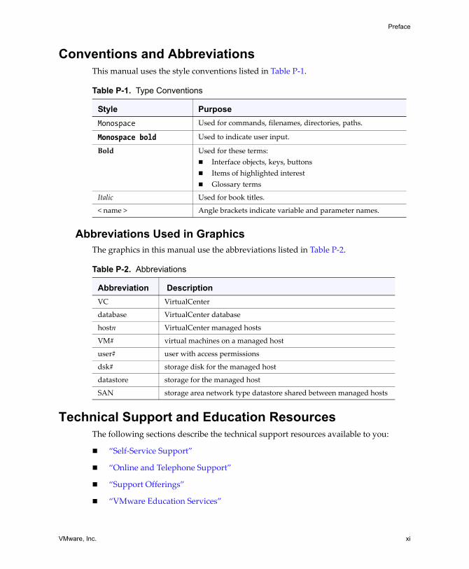
Conventions and AbbreviationsThis manual uses the style conventions listed in Table P‐1.
Abbreviations Used in GraphicsThe graphics in this manual use the abbreviations listed in Table P‐2.
Technical Support and Education ResourcesThe following sections describe the technical support resources available to you:
! �Self‐Service Support�
! �Online and Telephone Support�
! �Support Offerings�
! �VMware Education Services�
Table P-1. Type Conventions
Style PurposeMonospace Used for commands, filenames, directories, paths.
Monospace bold Used to indicate user input.
Bold Used for these terms:! Interface objects, keys, buttons! Items of highlighted interest! Glossary terms
Italic Used for book titles.
< name > Angle brackets indicate variable and parameter names.
Table P-2. Abbreviations
Abbreviation DescriptionVC VirtualCenter
database VirtualCenter database
hostn VirtualCenter managed hosts
VM# virtual machines on a managed host
user# user with access permissions
dsk# storage disk for the managed host
datastore storage for the managed host
SAN storage area network type datastore shared between managed hosts
SAN Configuration Guide
xii VMware, Inc.
Self-Service SupportUse the VMware Technology Network for self‐help tools and technical information:
! Product Information � http://www.vmware.com/products/
! Technology Information � http://www.vmware.com/vcommunity/technology
! Documentation � http://www.vmware.com/support/pubs
! Knowledge Base � http://www.vmware.com/support/kb
! Discussion Forums � http://www.vmware.com/community
! User Groups � http://www.vmware.com/vcommunity/usergroups.html
Go to http://www.vmtn.net for more information about the VMware Technology Network.
Online and Telephone SupportUse online support to submit technical support requests, view your product and contract information, and register your products. Go to http://www.vmware.com/support.
Customers with appropriate support contracts can use telephone support for the fastest response on priority 1 issues. Go to http://www.vmware.com/support/phone_support.html.
Support OfferingsFind out how VMwareʹs support offerings can help you meet your business needs. Go to http://www.vmware.com/support/services.
VMware Education ServicesVMware courses offer extensive hands‐on labs, case study examples, and course materials designed to be used as on‐the‐job reference tools. For more information about VMware Education Services, go to http://mylearn1.vmware.com/mgrreg/index.cfm.
VMware, Inc. 1
CHAPTER 1 Overview of VMware ESX Server
Using ESX Server together with a SAN (storage area network) helps provide extra storage for consolidation, can improve reliability, and can help with disaster recovery. To use ESX Server effectively with a SAN, you must have a working knowledge of both ESX Server systems and SAN concepts. This chapter presents an overview of ESX Server concepts. It is meant for SAN administrators not yet familiar with ESX Server systems and consists of the following sections:
! �Introduction� on page 2! �Understanding Virtualization� on page 5! �Interacting with ESX Server Systems� on page 9! �Virtualization at a Glance� on page 12
For in‐depth information on VMware ESX Server, go to http://www.vmware.com/products/esx/ and choose the information under Technical Resources. The section includes documentation, hardware compatibility lists, white papers, and more.
SAN Configuration Guide
2 VMware, Inc.
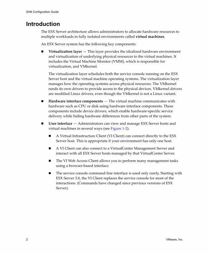
IntroductionThe ESX Server architecture allows administrators to allocate hardware resources to multiple workloads in fully isolated environments called virtual machines.
An ESX Server system has the following key components:
! Virtualization layer � This layer provides the idealized hardware environment and virtualization of underlying physical resources to the virtual machines. It includes the Virtual Machine Monitor (VMM), which is responsible for virtualization, and VMkernel.
The virtualization layer schedules both the service console running on the ESX Server host and the virtual machine operating systems. The virtualization layer manages how the operating systems access physical resources. The VMkernel needs its own drivers to provide access to the physical devices. VMkernel drivers are modified Linux drivers, even though the VMkernel is not a Linux variant.
! Hardware interface components � The virtual machine communicates with hardware such as CPU or disk using hardware interface components. These components include device drivers, which enable hardware‐specific service delivery while hiding hardware differences from other parts of the system.
! User interface � Administrators can view and manage ESX Server hosts and virtual machines in several ways (see Figure 1‐2).
! A Virtual Infrastructure Client (VI Client) can connect directly to the ESX Server host. This is appropriate if your environment has only one host.
! A VI Client can also connect to a VirtualCenter Management Server and interact with all ESX Server hosts managed by that VirtualCenter Server.
! The VI Web Access Client allows you to perform many management tasks using a browser‐based interface.
! The service console command‐line interface is used only rarely. Starting with ESX Server 3.0, the VI Client replaces the service console for most of the interactions. (Commands have changed since previous versions of ESX Server).
VMware, Inc. 3
Chapter 1 Overview of VMware ESX Server
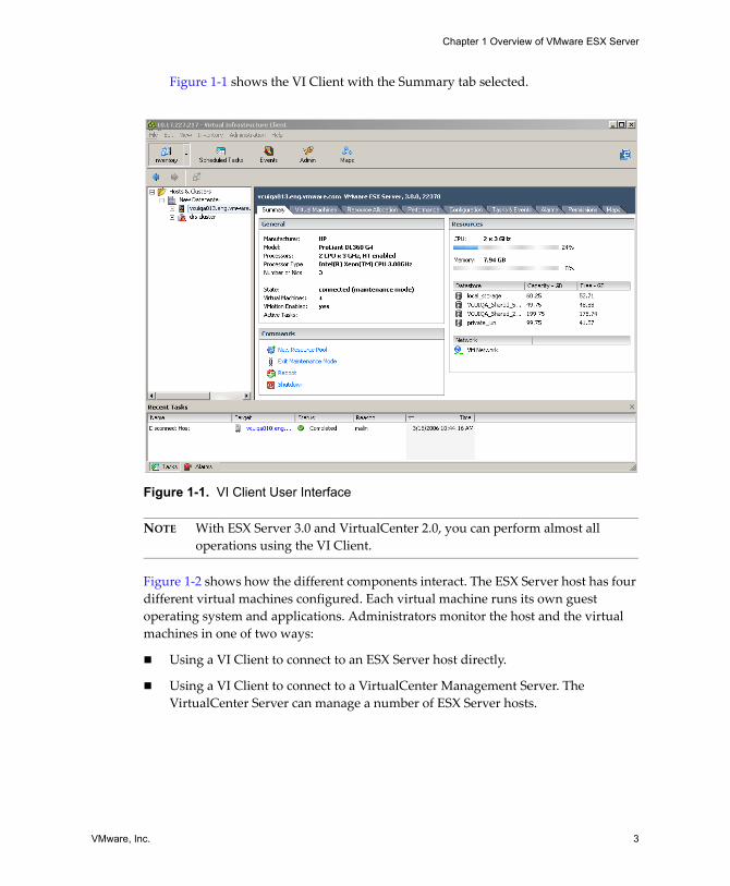
Figure 1‐1 shows the VI Client with the Summary tab selected.
Figure 1-1. VI Client User Interface
NOTE With ESX Server 3.0 and VirtualCenter 2.0, you can perform almost all operations using the VI Client.
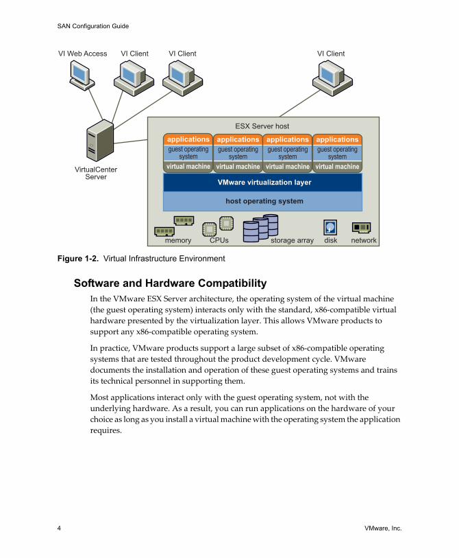
Figure 1‐2 shows how the different components interact. The ESX Server host has four different virtual machines configured. Each virtual machine runs its own guest operating system and applications. Administrators monitor the host and the virtual machines in one of two ways:
! Using a VI Client to connect to an ESX Server host directly.
! Using a VI Client to connect to a VirtualCenter Management Server. The VirtualCenter Server can manage a number of ESX Server hosts.
SAN Configuration Guide
4 VMware, Inc.
Figure 1-2. Virtual Infrastructure Environment
Software and Hardware CompatibilityIn the VMware ESX Server architecture, the operating system of the virtual machine (the guest operating system) interacts only with the standard, x86‐compatible virtual hardware presented by the virtualization layer. This allows VMware products to support any x86‐compatible operating system.
In practice, VMware products support a large subset of x86‐compatible operating systems that are tested throughout the product development cycle. VMware documents the installation and operation of these guest operating systems and trains its technical personnel in supporting them.
Most applications interact only with the guest operating system, not with the underlying hardware. As a result, you can run applications on the hardware of your choice as long as you install a virtual machine with the operating system the application requires.
CPUsmemory
VirtualCenterServer
VI ClientVI Web Access
ESX Server host
VI Client VI Client
storage array disk network
VMware virtualization layer
host operating system
applications
virtual machine
guest operatingsystem
applications
virtual machine
guest operatingsystem
applications
virtual machine
guest operatingsystem
applications
virtual machine
guest operatingsystem
VMware, Inc. 5
Chapter 1 Overview of VMware ESX Server
Understanding VirtualizationThe VMware virtualization layer is common across VMware desktop products (such as VMware Workstation) and server products (such as VMware ESX Server). This layer provides a consistent platform for development, testing, delivery, and support of application workloads and is organized as follows:
! Each virtual machine runs its own operating system (the guest operating system) and applications.
! The virtualization layer provides the virtual devices that map to shares of specific physical devices. These devices include virtualized CPU, memory, I/O buses, network interfaces, storage adapters and devices, human interface devices, and BIOS.
The following aspects of virtualization are of particular interest:
! �CPU, Memory, and Network Virtualization� on page 5! �Virtual SCSI� on page 6
CPU, Memory, and Network VirtualizationA VMware virtual machine offers complete hardware virtualization. The guest operating system and applications running on a virtual machine can never determine directly which physical resources they are accessing (such as which physical CPU they are running on in a multiprocessor system, or which physical memory is mapped to their pages).
! CPU Virtualization � Each virtual machine appears to run on its own CPU (or a set of CPUs), fully isolated from other virtual machines. Registers, the translation lookaside buffer, and other control structures are maintained separately for each virtual machine.
Most instructions are executed directly on the physical CPU, allowing resource‐intensive workloads to run at near‐native speed. Privileged instructions are performed safely by the virtualization layer.
See the Resource Management Guide for more information.
! Memory Virtualization � A contiguous memory space is visible to each virtual machine; however, the allocated physical memory might not be contiguous. Instead, noncontiguous physical pages are remapped and presented to each virtual machine. With unusually memory‐intensive loads, server memory becomes overcommitted. In that case, some of the physical memory of a virtual machine might be mapped to shared pages or to pages that are unmapped or swapped out.
SAN Configuration Guide
6 VMware, Inc.
ESX Server performs this virtual memory management without the information the guest operating system has, and without interfering with the guest operating system�s memory management subsystem.
See the Resource Management Guide for more information.
! Network Virtualization � The virtualization layer guarantees that each virtual machine is isolated from other virtual machines. Virtual machines can talk to each other only via networking mechanisms similar to those used to connect separate physical machines.
The isolation allows administrators to build internal firewalls or other network isolation environments, allowing some virtual machines to connect to the outside while others are connected only via virtual networks through other virtual machines.
See the Server Configuration Guide for more information.
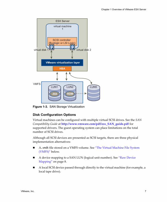
Virtual SCSIIn an ESX Server environment, each virtual machine includes from one to four virtual SCSI HBAs (host bus adapters). These virtual adapters may appear as either Buslogic or LSI Logic SCSI controllers. They are they only types of SCSI controllers that are accessible by a virtual machine.
Each virtual disk accessible by a virtual machine through one of the virtual SCSI adapters resides in the VMFS or on a raw disk. See �The Virtual Machine File System (VMFS)� on page 8 and �Raw Device Mapping� on page 8.
�SAN Storage Virtualization� on page 7 gives an overview of storage virtualization. It illustrates both storage using VMFS and storage using raw device mapping.
VMware, Inc. 7
Chapter 1 Overview of VMware ESX Server
Figure 1-3. SAN Storage Virtualization
Disk Configuration OptionsVirtual machines can be configured with multiple virtual SCSI drives. See the SAN Compatibility Guide at http://www.vmware.com/pdf/esx_SAN_guide.pdf for supported drivers. The guest operating system can place limitations on the total number of SCSI drives.
Although all SCSI devices are presented as SCSI targets, there are three physical implementation alternatives:
! A.vmdk file stored on a VMFS volume. See �The Virtual Machine File System (VMFS)� below.
! A device mapping to a SAN LUN (logical unit number). See �Raw Device Mapping� on page 8.
! A local SCSI device passed through directly to the virtual machine (for example, a local tape drive).
virtual machine1
VMFS
ESX Server
HBA
VMware virtualization layer
.dsk
LUN1 LUN2 LUN5
RDM
SCSI controller (Buslogic or LSI Logic)
virtual disk 2virtual disk 1
SAN Configuration Guide
8 VMware, Inc.
From the standpoint of the virtual machine, each virtual disk appears as if it were a SCSI drive connected to a SCSI adapter. Whether the actual physical disk device is being accessed through SCSI, iSCSI, RAID, NFS, or Fibre Channel (FC) controllers is transparent to the guest operating system and to applications running on the virtual machine.
The Virtual Machine File System (VMFS)In a simple configuration, the virtual machines� disks are stored as files within a VMFS. When guest operating systems issue SCSI commands to their virtual disks, the virtualization layer translates these commands to VMFS file operations.
ESX Server systems use VMFS to store virtual machine files. To minimize disk I/O overhead, VMFS has been optimized to run multiple virtual machines as one workload. VMFS also provides distributed locking for your virtual machine files, so that your virtual machines can operate safely in a SAN environment where multiple ESX Server hosts share a set of LUNs.
VMFS is first configured as part of the ESX Server installation. When you create a new VMFS‐3 volume, it must be 600MB or larger. See the Installation and Upgrade Guide. It can then be customized, as discussed in the Server Configuration Guide.
A VMFS volume can be extended over 32 physical storage extents, including SAN LUNs and local storage. This allows pooling of storage and flexibility in creating the storage volume necessary for your virtual machine. With the new ESX3 Logical Volume Manager (LVM), you can extend a volume while virtual machines are running on the volume. This lets you add new space to your VMFS volumes as your virtual machine needs it.
The HBAs and storage devices that are supported by ESX Server systems are listed in Chapter 4, �Requirements and Installation,� on page 47. Chapter 5, �Setting Up SAN Storage Devices with ESX Server,� on page 55 provides information on configuring these SAN components.
Raw Device MappingA Raw Device Mapping (RDM) is a special file in a VMFS volume that acts as a proxy for a raw device. The RDM provides some of the advantages of a virtual disk in the VMFS file system while keeping some advantages of direct access to physical devices.
RDM might be required if you use Microsoft Cluster Service (MSCS) or if you run SAN snapshot or other layered applications in the virtual machine. RDMs better enable systems to use the hardware features inherent to SAN arrays. For information, see �Using Raw Device Mapping� in the Server Configuration Guide. See the document Setup for Microsoft Cluster Service for information about MSCS.
VMware, Inc. 9
Chapter 1 Overview of VMware ESX Server
Virtual SCSI HBAVirtual SCSI HBAs allow virtual machines access to logical SCSI devices, just as a physical HBA allows access to physical storage devices. However, in contrast to the physical HBA, the virtual SCSI HBA does not allow storage administrators (such as SAN administrators) access to the physical machine. At the same time, many virtual HBAs can be hidden behind a single (or multiple) FC HBAs. The SAN can see only the physical machine and its HBAs.
Interacting with ESX Server SystemsAdministrators interact with ESX Server systems using a client (VI Client or VI Web Access), as discussed in the �Introduction� on page 2. Clients can be connected directly to the ESX Server host, or you can manage multiple ESX Server hosts simultaneously using the VirtualCenter Management Server. See �VMware Virtual Center� below.
NOTE In ESX Server 3.0 and later, administrative operations are performed using a VI Client or VI Web Access. Use of the service console is generally not necessary and is discouraged. For scripted management, you are encouraged to use the Virtual Infrastructure SDK.
VMware Virtual CenterA VirtualCenter Server can be accessed via a VI Client or VI Web Access.
! The VirtualCenter Server acts as a central administrator for VMware servers connected on a network. The server directs actions upon the virtual machines and VMware ESX Server.
! The VI Client user interface runs on Microsoft Windows. In a multi‐host environment, administrators use the VI Client to make requests to the VirtualCenter server, which in turn affects its virtual machines and hosts. Connecting to an ESX Server host directly usually makes sense only in a single‐server environment.
! VI Web Access allows you to connect to a VirtualCenter Server using an HTML browser.
SAN Configuration Guide
10 VMware, Inc.
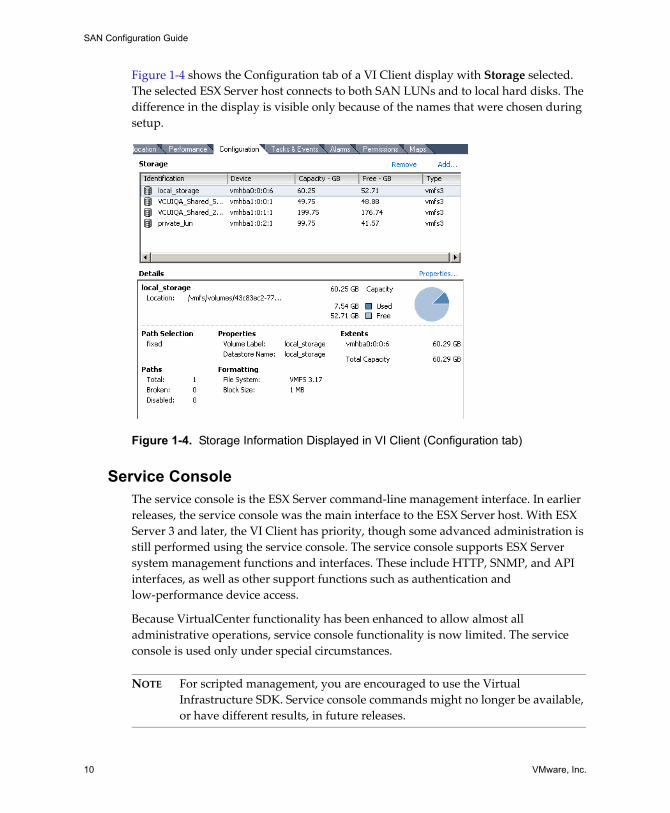
Figure 1‐4 shows the Configuration tab of a VI Client display with Storage selected. The selected ESX Server host connects to both SAN LUNs and to local hard disks. The difference in the display is visible only because of the names that were chosen during setup.
Figure 1-4. Storage Information Displayed in VI Client (Configuration tab)
Service ConsoleThe service console is the ESX Server command‐line management interface. In earlier releases, the service console was the main interface to the ESX Server host. With ESX Server 3 and later, the VI Client has priority, though some advanced administration is still performed using the service console. The service console supports ESX Server system management functions and interfaces. These include HTTP, SNMP, and API interfaces, as well as other support functions such as authentication and low‐performance device access.
Because VirtualCenter functionality has been enhanced to allow almost all administrative operations, service console functionality is now limited. The service console is used only under special circumstances.
NOTE For scripted management, you are encouraged to use the Virtual Infrastructure SDK. Service console commands might no longer be available, or have different results, in future releases.
VMware, Inc. 11
Chapter 1 Overview of VMware ESX Server
The service console is implemented using a modified Linux distribution; however, the service console does not correspond directly to a Linux command prompt.
Service Console Processes and ServicesThe following ESX Server management processes and services run in the service console:
! Host daemon (hostd) � Performs actions in the service console on behalf of the service console and the VI Client.
! Authentication daemon (vmauthd) � Authenticates remote users of the VI Client and remote consoles using the user name and password database. Any other authentication store that can be accessed using the service console�s Pluggable Authentication Module (PAM) capabilities can also be used. Having multiple password storage mechanisms permits the use of passwords from a Windows domain controller, LDAP or RADIUS server, or similar central authentication store in conjunction with VMware ESX Server for remote access.
! SNMP server (net‐snmpd) � Implements the SNMP traps and data structures that an administrator can use to integrate an ESX Server system into an SNMP‐based system‐management tool.
In addition to these services, which are supplied by VMware, the service console can be used to run other system‐wide or hardware‐dependent management tools. These can include hardware‐specific health monitors (such as IBM Director or HP Insight Manager), full‐system backup and disaster recovery software, and clustering and high availability products.
NOTE The service console is not guaranteed to be available for general‐purpose Linux hardware monitoring; it is not equivalent to a Linux shell.
SAN Configuration Guide
12 VMware, Inc.
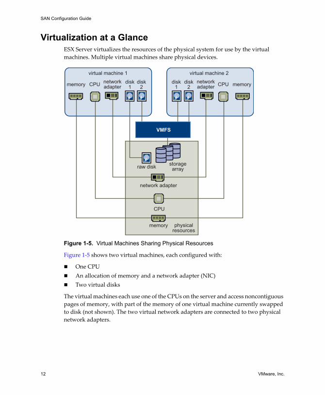
Virtualization at a GlanceESX Server virtualizes the resources of the physical system for use by the virtual machines. Multiple virtual machines share physical devices.
Figure 1-5. Virtual Machines Sharing Physical Resources
Figure 1‐5 shows two virtual machines, each configured with:
! One CPU! An allocation of memory and a network adapter (NIC)! Two virtual disks
The virtual machines each use one of the CPUs on the server and access noncontiguous pages of memory, with part of the memory of one virtual machine currently swapped to disk (not shown). The two virtual network adapters are connected to two physical network adapters.
CPU
CPU CPU
memory
memory memory
storagearrayraw disk
disk1
disk2
disk2
disk1
network adapter
networkadapter
networkadapter
VMFS
physicalresources
virtual machine 1 virtual machine 2
VMware, Inc. 13
Chapter 1 Overview of VMware ESX Server
The disks are mapped as follows:
! Disk 1 of virtual machine 1 is mapped directly to a raw disk. This configuration is not usually recommended but can be advantageous under certain circumstances.
! Disk 2 of virtual machine 1 and both disks of virtual machine 2 reside on the VMFS, which is located on a SAN storage array. VMFS makes sure that appropriate locking and security is in place at all times.

SAN Configuration Guide
14 VMware, Inc.
VMware, Inc. 15
CHAPTER 2 Storage Area Network Concepts
This chapter presents an overview of storage area networks. The chapter gives a basic introduction for ESX Server administrators. Pointers to more detailed information are included. The chapter discusses these topics:
! �SAN Basics� on page 16! �SAN Components� on page 18! �Understanding SAN Interactions� on page 21! �Information on SANs� on page 25
NOTE SAN administrators can skip this chapter and continue with Chapter 3, �Using ESX Server with SAN: Concepts,� on page 27.
SAN Configuration Guide
16 VMware, Inc.
SAN BasicsA SAN is a specialized high‐speed network of storage devices and switches connected to computer systems. This guide refers to the computer systems as servers or hosts.
A SAN presents shared pools of storage devices to multiple servers. Each server can access the storage as if it were directly attached to that server. A SAN supports centralized storage management. SANs make it possible to move data between various storage devices, share data between multiple servers, and back up and restore data rapidly and efficiently. In addition, a properly configured SAN facilitates both disaster recovery and high availability.
The physical components of a SAN can be grouped in a single rack or data center or connected over long distances. This makes a SAN a feasible solution for businesses of any size: the SAN can grow easily with the business it supports.
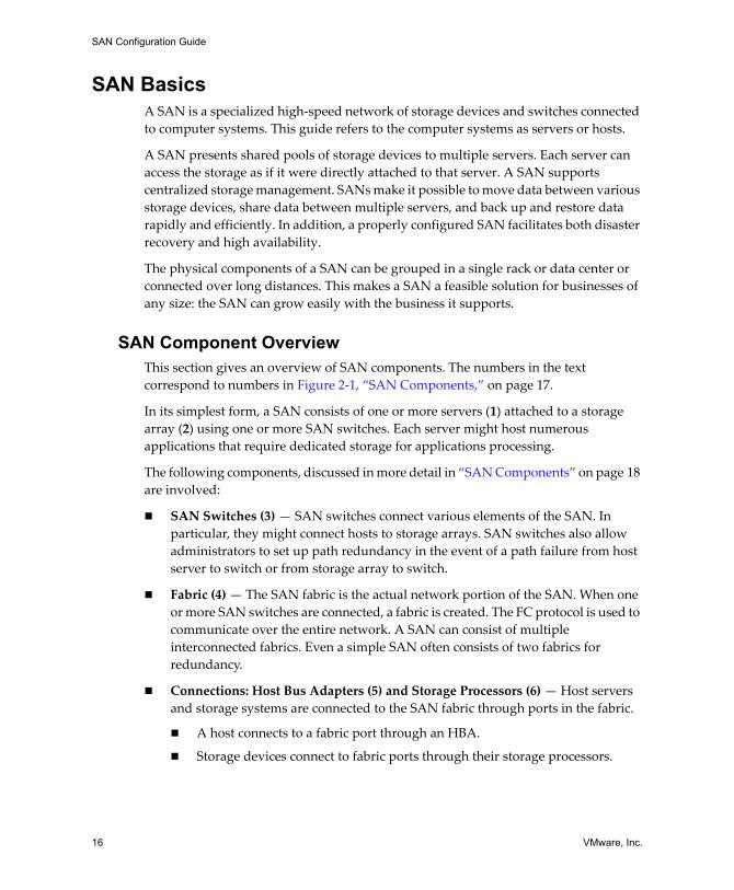
SAN Component OverviewThis section gives an overview of SAN components. The numbers in the text correspond to numbers in Figure 2‐1, �SAN Components,� on page 17.
In its simplest form, a SAN consists of one or more servers (1) attached to a storage array (2) using one or more SAN switches. Each server might host numerous applications that require dedicated storage for applications processing.
The following components, discussed in more detail in �SAN Components� on page 18 are involved:
! SAN Switches (3) � SAN switches connect various elements of the SAN. In particular, they might connect hosts to storage arrays. SAN switches also allow administrators to set up path redundancy in the event of a path failure from host server to switch or from storage array to switch.
! Fabric (4) � The SAN fabric is the actual network portion of the SAN. When one or more SAN switches are connected, a fabric is created. The FC protocol is used to communicate over the entire network. A SAN can consist of multiple interconnected fabrics. Even a simple SAN often consists of two fabrics for redundancy.
! Connections: Host Bus Adapters (5) and Storage Processors (6) � Host servers and storage systems are connected to the SAN fabric through ports in the fabric.
! A host connects to a fabric port through an HBA.
! Storage devices connect to fabric ports through their storage processors.
VMware, Inc. 17
Chapter 2 Storage Area Network Concepts
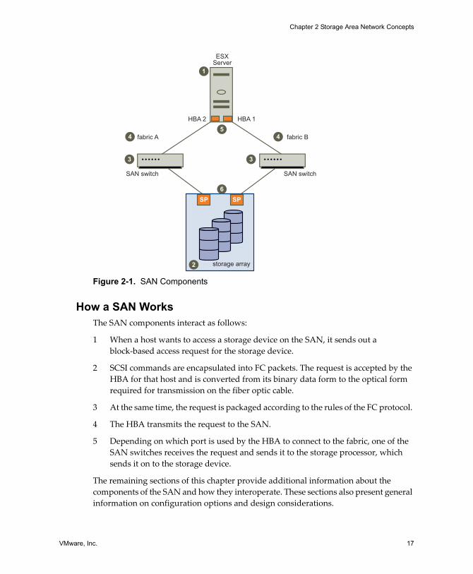
Figure 2-1. SAN Components
How a SAN WorksThe SAN components interact as follows:
1 When a host wants to access a storage device on the SAN, it sends out a block‐based access request for the storage device.
2 SCSI commands are encapsulated into FC packets. The request is accepted by the HBA for that host and is converted from its binary data form to the optical form required for transmission on the fiber optic cable.
3 At the same time, the request is packaged according to the rules of the FC protocol.
4 The HBA transmits the request to the SAN.
5 Depending on which port is used by the HBA to connect to the fabric, one of the SAN switches receives the request and sends it to the storage processor, which sends it on to the storage device.
The remaining sections of this chapter provide additional information about the components of the SAN and how they interoperate. These sections also present general information on configuration options and design considerations.
ESXServer
storage array
SAN switch SAN switch
fabric A
HBA 2 HBA 1
fabric B
SP SP
1
5
3 3
2
6
4 4
SAN Configuration Guide
18 VMware, Inc.
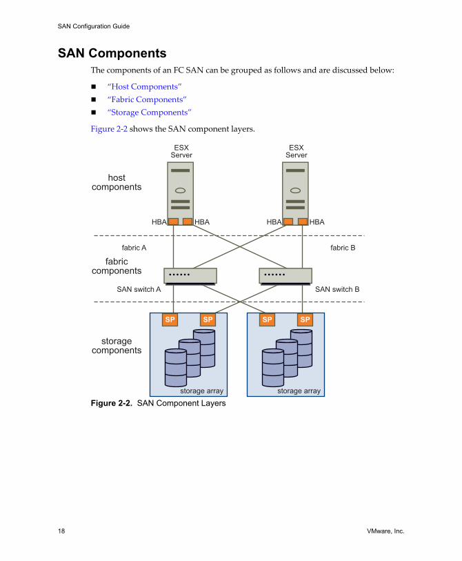
SAN ComponentsThe components of an FC SAN can be grouped as follows and are discussed below:
! �Host Components�! �Fabric Components�! �Storage Components�
Figure 2‐2 shows the SAN component layers.
Figure 2-2. SAN Component Layers
ESXServer
ESXServer
storage array
hostcomponents
fabriccomponents
storagecomponents
SP SP
storage array
SP SP
SAN switch A SAN switch B
HBA HBA HBA HBA
fabric Bfabric A
VMware, Inc. 19
Chapter 2 Storage Area Network Concepts
Host ComponentsThe host components of a SAN consist of the servers themselves and the components that enable the servers to be physically connected to the SAN.
! HBAs are located in the servers, along with a component that performs digital‐to‐optical signal conversion. Each host connects to the fabric ports through its HBAs.
! HBA drivers running on the servers enable the servers� operating systems to communicate with the HBA.
Fabric ComponentsAll hosts connect to the storage devices on the SAN through the SAN fabric. The network portion of the SAN consists of the following fabric components:
! SAN Switches � SAN switches can connect to servers, storage devices, and other switches, and thus provide the connection points for the SAN fabric. The type of SAN switch, its design features, and its port capacity all contribute to its overall capacity, performance, and fault tolerance. The number of switches, types of switches, and manner in which the switches are interconnected define the fabric topology.
! For smaller SANs, the standard SAN switches (called modular switches) can typically support 16 or 24 ports (though some 32‐port modular switches are becoming available). Sometimes modular switches are interconnected to create a fault‐tolerant fabric.
! For larger SAN fabrics, director‐class switches provide a larger port capacity (64 to 128 ports per switch) and built‐in fault tolerance.
! Data Routers � Data routers are intelligent bridges between SCSI devices and FC devices in the SAN. Servers in the SAN can access SCSI disk or tape devices in the SAN through the data routers in the fabric layer.
! Cables � SAN cables are usually special fiber optic cables that are used to connect all of the fabric components. The type of SAN cable and the fiber optic signal determine the maximum distances between SAN components and contribute to the total bandwidth rating of the SAN.
! Communications Protocol � Fabric components communicate using the FC communications protocol. FC is the storage interface protocol used for most of today�s SANs. FC was developed as a protocol for transferring data between two ports on a serial I/O bus cable at high speeds. FC supports point‐to‐point, arbitrated loop, and switched fabric topologies. Switched fabric topology is the basis for most current SANs.
SAN Configuration Guide
20 VMware, Inc.
Storage ComponentsThe storage components of a SAN are the storage arrays. Storage arrays include storage processors (SPs). The SPs are the front end of the storage array. SPs communicate with the disk array (which includes all the disks in the storage array) and provide the RAID/LUN functionality.
Storage ProcessorsSPs provide front‐side host attachments to the storage devices from the servers, either directly or through a switch. The server HBAs must conform to the protocol supported by the storage processor. In most cases, this is the FC protocol.
Storage processors provide internal access to the drives, which can be using a switch or bus architecture. In high‐end storage systems, drives are normally connected in loops. This back‐end loop technology employed by the SP provides several benefits:
! High‐speed access to the drives
! Ability to add more drives to the loop
! Redundant access to a single drive from multiple loops (when drives are dual‐ported and attached to two loops)
Storage Devices Data is stored on disk arrays or tape devices (or both).
Disk arrays are groups of multiple disk devices and are the typical SAN disk storage device. They can vary greatly in design, capacity, performance, and other features.
Storage arrays rarely provide hosts direct access to individual drives. Instead, the storage array uses RAID (Redundant Array of Independent Drives) technology to group a set of drives. RAID uses independent drives to provide capacity, performance, and redundancy. Using specialized algorithms, several drives are grouped to provide common pooled storage. These RAID algorithms, commonly known as RAID levels, define the characteristics of the particular grouping.
In simple systems that provide RAID capability, a RAID group is equivalent to a single LUN. A LUN is a single unit of storage. Depending on the host system environment, a LUN is also known as a volume or a logical drive. From a VI Client, a LUN looks like any other storage unit available for access.
In advanced storage arrays, RAID groups can have one or more LUNs created for access by one or more servers. The ability to create more than one LUN from a single RAID group provides fine granularity to the storage creation process. You are not limited to the total capacity of the entire RAID group for a single LUN.

VMware, Inc. 21
Chapter 2 Storage Area Network Concepts
NOTE A SAN administrator must be familiar with the different RAID levels and understand how to manage them. Discussion of those topics is beyond the scope of this document.
Most storage arrays provide additional data protection and replication features such as snapshots, internal copies, and remote mirroring.
! A snapshot is a point‐in‐time copy of a LUN. Snapshots are used as backup sources for the overall backup procedures defined for the storage array.
! Internal copies allow data movement from one LUN to another for an additional copy for testing.
! Remote mirroring provides constant synchronization between LUNs on one storage array and a second, independent (usually remote) storage array for disaster recovery.
Tape Storage DevicesTape storage devices are part of the SAN backup capabilities and processes.
! Smaller SANs might use high‐capacity tape drives. These tape drives vary in their transfer rates and storage capacities. A high‐capacity tape drive might exist as a standalone drive, or it might be part of a tape library.
! Typically, a large SAN, or a SAN with critical backup requirements, is configured with one or more tape libraries. A tape library consolidates one or more tape drives into a single enclosure. Tapes can be inserted and removed from the tape drives in the library automatically with a robotic arm. Many tape libraries offer large storage capacities�sometimes into the petabyte (PB) range.
Understanding SAN InteractionsThe previous section�s primary focus was the components of a SAN. This section discusses how SAN components interact:
! �SAN Ports and Port Naming� on page 22! �Multipathing and Path Failover� on page 22! �Active/Active and Active/Passive Disk Arrays� on page 23! �Zoning� on page 23
SAN Configuration Guide
22 VMware, Inc.
SAN Ports and Port NamingIn the context of this document, a port is the connection from a device into the SAN. Each node in the SAN� each host, storage device, and fabric component (router or switch)�has one or more ports that connect it to the SAN. Ports can be identified in a number of ways:
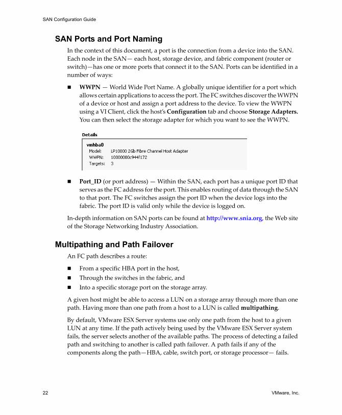
! WWPN � World Wide Port Name. A globally unique identifier for a port which allows certain applications to access the port. The FC switches discover the WWPN of a device or host and assign a port address to the device. To view the WWPN using a VI Client, click the host�s Configuration tab and choose Storage Adapters. You can then select the storage adapter for which you want to see the WWPN.
! Port_ID (or port address) � Within the SAN, each port has a unique port ID that serves as the FC address for the port. This enables routing of data through the SAN to that port. The FC switches assign the port ID when the device logs into the fabric. The port ID is valid only while the device is logged on.
In‐depth information on SAN ports can be found at http://www.snia.org, the Web site of the Storage Networking Industry Association.
Multipathing and Path FailoverAn FC path describes a route:
! From a specific HBA port in the host, ! Through the switches in the fabric, and ! Into a specific storage port on the storage array.
A given host might be able to access a LUN on a storage array through more than one path. Having more than one path from a host to a LUN is called multipathing.
By default, VMware ESX Server systems use only one path from the host to a given LUN at any time. If the path actively being used by the VMware ESX Server system fails, the server selects another of the available paths. The process of detecting a failed path and switching to another is called path failover. A path fails if any of the components along the path�HBA, cable, switch port, or storage processor� fails.
VMware, Inc. 23
Chapter 2 Storage Area Network Concepts
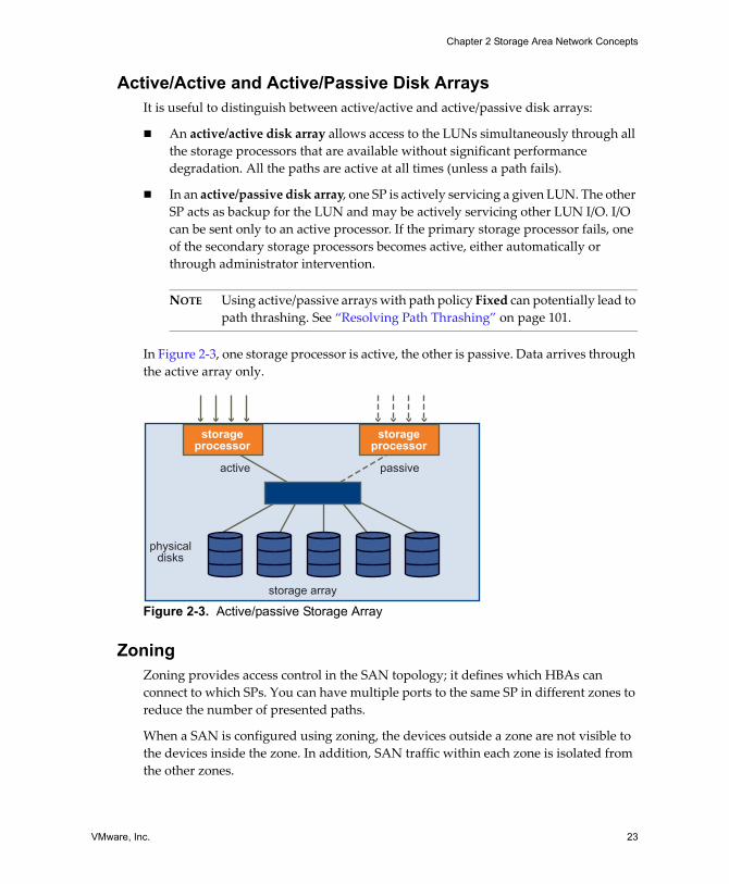
Active/Active and Active/Passive Disk ArraysIt is useful to distinguish between active/active and active/passive disk arrays:
! An active/active disk array allows access to the LUNs simultaneously through all the storage processors that are available without significant performance degradation. All the paths are active at all times (unless a path fails).
! In an active/passive disk array, one SP is actively servicing a given LUN. The other SP acts as backup for the LUN and may be actively servicing other LUN I/O. I/O can be sent only to an active processor. If the primary storage processor fails, one of the secondary storage processors becomes active, either automatically or through administrator intervention.
NOTE Using active/passive arrays with path policy Fixed can potentially lead to path thrashing. See �Resolving Path Thrashing� on page 101.
In Figure 2‐3, one storage processor is active, the other is passive. Data arrives through the active array only.
Figure 2-3. Active/passive Storage Array
ZoningZoning provides access control in the SAN topology; it defines which HBAs can connect to which SPs. You can have multiple ports to the same SP in different zones to reduce the number of presented paths.
When a SAN is configured using zoning, the devices outside a zone are not visible to the devices inside the zone. In addition, SAN traffic within each zone is isolated from the other zones.
storage array
active passive
physicaldisks
storageprocessor
storageprocessor
SAN Configuration Guide
24 VMware, Inc.
Within a complex SAN environment, SAN switches provide zoning. Zoning defines and configures the necessary security and access rights for the entire SAN.
Typically, zones are created for each group of servers that access a shared group of storage devices and LUNs. You can use zoning in several ways. Here are some examples:
! Zoning for security and isolation � You can manage zones defined for testing independently within the SAN so they don�t interfere with the activity going on in the production zones. Similarly, you could set up different zones for different departments.
! Zoning for shared services � Another use of zones is to allow common server access for backups. SAN designs often have a backup server with tape services that require SAN‐wide access to host servers individually for backup and recovery processes. These backup servers need to be able to access the servers they back up. A SAN zone might be defined for the backup server to access a particular host to perform a backup or recovery process. The zone is then redefined for access to another host when the backup server is ready to perform backup or recovery processes on that host.
! Multiple storage arrays � Zones are also useful when there are multiple storage arrays. Through the use of separate zones, each storage array is managed separately from the others, with no concern for access conflicts between servers.
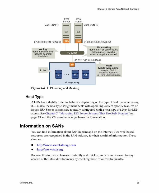
LUN MaskingLUN masking is commonly used for permission management. LUN masking is also referred to as selective storage presentation, access control, and partitioning, depending on the vendor.
LUN masking is performed at the SP or server level; it makes a LUN invisible when a target is scanned. The administrator configures the disk array so each server or group of servers can see only certain LUNs. Masking capabilities for each disk array are vendor specific, as are the tools for managing LUN masking.
VMware, Inc. 25
Chapter 2 Storage Area Network Concepts
Figure 2-4. LUN Zoning and Masking
Host TypeA LUN has a slightly different behavior depending on the type of host that is accessing it. Usually, the host type assignment deals with operating‐system‐specific features or issues. ESX Server systems are typically configured with a host type of Linux for LUN access. See Chapter 7, �Managing ESX Server Systems That Use SAN Storage,� on page 79 and the VMware knowledge bases for information.
Information on SANsYou can find information about SAN in print and on the Internet. Two web‐based resources are recognized in the SAN industry for their wealth of information. These sites are:
! http://www.searchstorage.com! http://www.snia.org
Because this industry changes constantly and quickly, you are encouraged to stay abreast of the latest developments by checking these resources frequently.
ESXServer
ESXServer
zoning:done at switch level;
used to segmentthe fabric
LUNs
LUN masking:done at SP or server level;
makes a LUN invisiblewhen a target is scanned
storage array
SP
0 11 12
FC switch
HBAHBA
Mask LUN 11
21:00:00:E0:8B:19:AB:31 21:00:00:E0:8B:19:B2:33
50:05:01:60:10:20:AD:87
Mask LUN 12
WWN(world-wide name)
unique, 64-bit address assigned
to Fibre Channel node

SAN Configuration Guide
26 VMware, Inc.
VMware, Inc. 27
CHAPTER 3 Using ESX Server with SAN: Concepts
When ESX Server administrators set up ESX Server hosts to use FC SAN array storage, some special considerations are necessary. When SAN administrators configure a SAN array for use by an ESX Server host and its virtual machines, some aspects of configuration and setup are different. This chapter gives some introductory information on using ESX Server with a SAN array for both types of administrator.
The chapter discusses these topics:
! �Introduction� on page 28! �Using SAN Arrays with ESX Server� on page 30! �Understanding VMFS and SAN Storage Choices� on page 35! �Understanding Data Access� on page 37! �Path Management and Failover� on page 40! �Choosing Virtual Machine Locations� on page 41! �Designing for Server Failure� on page 42! �Optimizing Resource Utilization� on page 44
SAN Configuration Guide
28 VMware, Inc.
IntroductionSupport for QLogic and Emulex FC HBAs allows an ESX Server system to be connected to a SAN array. The virtual machines can then be stored on the SAN array LUNs and use the SAN array LUNs to store application data. Using ESX Server with a SAN improves flexibility, efficiency, and reliability. It also supports centralized management as well as failover and load balancing technologies.
BenefitsUsing a SAN with ESX Server allows you to improve your environment�s failure resilience:
! You can store data redundantly and configure multiple FC fabrics; eliminating a single point of failure. Your enterprise is not crippled when one datacenter becomes unavailable.
! ESX Server systems provide multipathing by default and automatically support it for every virtual machine. See �Path Management and Failover� on page 40.
! Using ESX Server systems extends failure resistance to the server. When you use SAN storage, all applications can instantly be restarted after host failure. See �Designing for Server Failure� on page 42.
Using ESX Server with a SAN makes high availability and automatic load balancing affordable for more applications than if dedicated hardware were used to provide standby services.
! Because shared central storage is available, building virtual machine clusters that use MSCS becomes possible. See �Server Failover and Storage Considerations� on page 43.
! If virtual machines are used as standby systems for existing physical servers, shared storage is essential and a SAN is the best solution.
! You can use the VMware VMotion capabilities to migrate virtual machines seamlessly from one host to another.
! You can use VMware HA in conjunction with a SAN for a cold‐standby solution that guarantees an immediate, automatic response.
! You can use VMware DRS to automatically migrate virtual machines from one host to another for load balancing. Because storage is on a SAN array, applications continue running seamlessly.
VMware, Inc. 29
Chapter 3 Using ESX Server with SAN: Concepts
! If you use VMware DRS clusters, you can put an ESX Server host into maintenance mode to have the system migrate all running virtual machines to other ESX Server hosts. You can then perform upgrades or other maintenance operations.
The transportability and encapsulation of VMware virtual machines complements the shared nature of SAN storage. When virtual machines are located on SAN‐based storage, it becomes possible to shut down a virtual machine on one server and power it up on another server�or to suspend it on one server and resume operation on another server on the same network�in a matter of minutes. This allows you to migrate computing resources while maintaining consistent shared access.
Use CasesUsing ESX Server systems in conjunction with SAN is particularly useful for the following tasks:
! Maintenance with zero downtime � When performing maintenance, you can use VMware DRS or VMotion to migrate virtual machines to other servers. If shared storage is on the SAN, you can perform maintenance without interruptions to the user.
! Load balancing � You can use VMotion explicitly or use VMware DRS to migrate virtual machines to other hosts for load balancing. If shared storage is on a SAN, you can perform load balancing without interruption to the user.
! Storage consolidation and simplification of storage layout � If you are working with multiple hosts, and each host is running multiple virtual machines, the hosts� storage is no longer sufficient and external storage is needed. Choosing a SAN for external storage results in a simpler system architecture while giving you the other benefits listed in this section. You can start by reserving a large LUN and then allocate portions to virtual machines as needed. LUN reservation and creation from the storage device needs to happen only once.
! Disaster recovery � Having all data stored on a SAN can greatly facilitate remote storage of data backups. In addition, you can restart virtual machines on remote ESX Server hosts for recovery if one site is compromised.
SAN Configuration Guide
30 VMware, Inc.
Finding InformationIn addition to this document, a number of other resources can help you configure your ESX Server system in conjunction with a SAN.
! Be sure to use your storage array vendor�s documentation for most setup questions. Your storage array vendor might also offer documentation on using the storage array in an ESX Server environment.
! VMware I/O Compatibility Guide � Lists the currently approved HBAs, HBA drivers, and driver versions. See http://www.vmware.com/pdf/esx_io_guide.pdf.
! VMware SAN Compatibility Guide � Lists currently approved storage arrays. See http://www.vmware.com/pdf/esx_SAN_guide.pdf.
! VMware Release Notes � Give information about known issues and workarounds.
! VMware Knowledge Bases � Have information on common issues and workarounds. See http://www.vmware.com/kb.
Using SAN Arrays with ESX ServerUsing a SAN in conjunction with an ESX Server host differs from traditional SAN usage in a variety of ways, discussed in this section:
! �Sharing a VMFS Across ESX Servers�! �Metadata Updates� on page 32! �LUN Display and Rescan� on page 32! �Levels of Indirection� on page 32! �Data Access: VMFS or RDM� on page 33! �Third‐Party Management Applications� on page 34
Sharing a VMFS Across ESX ServersESX Server VMFS is designed for concurrent access from multiple physical machines and enforces the appropriate access controls on virtual machine files. See �The Virtual Machine File System (VMFS)� on page 8 for some background information and the Server Configuration Guide for additional information. VMFS can:
! Coordinate access to virtual disk files � ESX Server uses file‐level locks, which are managed by the VMFS distributed lock manager.
! Coordinate access to VMFS internal file system information (metadata) � ESX Server uses SCSI reservations on the entire LUN. See �Metadata Updates� below.

VMware, Inc. 31
Chapter 3 Using ESX Server with SAN: Concepts
NOTE SCSI reservations are not held during metadata updates to the VMFS volume. ESX Server uses short‐lived SCSI reservations as part of its distributed locking protocol.
The fact that virtual machines share a common VMFS makes it more difficult to characterize peak‐access periods, or optimize performance. You need to plan virtual machine storage access for peak periods, but different applications might have different peak‐access periods. The more virtual machines are sharing a VMFS, the greater the potential for performance degradation due to I/O contention.
NOTE VMware recommends that you load balance virtual machines over servers, CPU, and storage. That means you run a mix of virtual machines on each given server so that not all experience high demand in the same area at the same time.
Figure 3-1. Accessing Virtual Disk Files
VMFS volume
ESXServer A
ESXServer B
ESXServer C
virtualdiskfiles
VM1 VM2 VM3
disk1
disk2
disk3
SAN Configuration Guide
32 VMware, Inc.
Metadata UpdatesA VMFS holds files, directories, symbolic links, RDMs, and so on, and corresponding metadata for these objects. Metadata is accessed each time the attributes of a file are accessed or modified. These operations include, but are not limited to:
! Creating, growing, or locking a file.! Changing a file�s attributes.! Powering a virtual machine on or off.
LUN Display and RescanA SAN is dynamic, and which LUNs are available to a certain host can change based on a number of factors including:
! New LUNS created on the SAN storage arrays! Changes to LUN masking! Changes in SAN connectivity or other aspects of the SAN
The VMkernel discovers LUNs when it boots, and those LUNs are then visible in the VI Client. If changes are made to the LUNs, you must rescan to see those changes.
Levels of IndirectionIf you�re used to working with traditional SANs, the levels of indirection can initially be confusing.
! You cannot directly access the virtual machine operating system that uses the storage. With traditional tools, you can monitor only the VMware ESX Server operating system (but not the virtual machine operating system). You use the VI Client to monitor virtual machines.
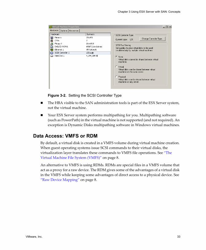
! Each virtual machine is, by default, configured with one (virtual) hard disk and one (virtual) SCSI Controller during installation. You can modify the SCSI Controller type and SCSI Bus Sharing characteristics by editing the virtual machine settings using the VI Client, as shown below. You can also add hard disks to your virtual machine. See the Server Configuration Guide for additional information.
VMware, Inc. 33
Chapter 3 Using ESX Server with SAN: Concepts
Figure 3-2. Setting the SCSI Controller Type
! The HBA visible to the SAN administration tools is part of the ESX Server system, not the virtual machine.
! Your ESX Server system performs multipathing for you. Multipathing software (such as PowerPath) in the virtual machine is not supported (and not required). An exception is Dynamic Disks multipathing software in Windows virtual machines.
Data Access: VMFS or RDMBy default, a virtual disk is created in a VMFS volume during virtual machine creation. When guest operating systems issue SCSI commands to their virtual disks, the virtualization layer translates these commands to VMFS file operations. See �The Virtual Machine File System (VMFS)� on page 8.
An alternative to VMFS is using RDMs. RDMs are special files in a VMFS volume that act as a proxy for a raw device. The RDM gives some of the advantages of a virtual disk in the VMFS while keeping some advantages of direct access to a physical device. See �Raw Device Mapping� on page 8.
SAN Configuration Guide
34 VMware, Inc.
Third-Party Management ApplicationsMost SAN hardware is packaged with SAN management software. This software typically runs on the storage array or on a single server, independent of the servers that use the SAN for storage. This third‐party management software can be used for a number of tasks:
! Storage array management including LUN creation, array cache management, LUN mapping, and LUN security.
! Setup of replication, checkpointing, snapshotting, or mirroring.
If you decide to run the SAN management software inside a virtual machine, you reap the benefits of running an application on a virtual machine (failover using VMotion, failover using VMware HA, and so on). Because of the additional level of indirection, however, the management software might not be able to see the SAN. This can be resolved by using an RDM. See �Layered Applications� on page 107 for more information.
NOTE Whether a virtual machine can run management software successfully depends on the storage array in question.
Zoning and ESX ServerZoning provides access control in the SAN topology; it defines which HBAs can connect to which SPs. When a SAN is configured using zoning, the devices outside a zone are not visible to the devices inside the zone. See �Zoning� on page 23.
Zoning has the following effects:
! Reduces the number of targets and LUNs presented to an ESX Server system.
! Controls and isolates paths within a fabric.
! Can prevent non‐ESX Server systems from seeing a particular storage system, and from possibly destroying ESX Server VMFS data.
! Can be used to separate different environments (for example, a test from a production environment).
VMware, Inc. 35
Chapter 3 Using ESX Server with SAN: Concepts
VMware recommends you use zoning with care. ESX Server hosts that use shared storage for failover or load balancing must be in one zone. If you have a very large deployment, you might decide to create separate zones for different areas of functionality (for example to separate accounting from human resources). It does not work well to create many small zones of, for example, two hosts with four virtual machines each.
NOTE Check with the storage array vendor for zoning best practices.
Access Control (LUN Masking) and ESX ServerAccess control allows you to limit the number of ESX Server hosts (or other hosts) that can see a LUN. Access control can be useful to:
! Reduce the number of LUNs presented to an ESX Server system.
! Prevent non‐ESX Server systems from seeing ESX Server LUNs and from possibly destroying VMFS volumes. See Figure 2‐4, �LUN Zoning and Masking,� on page 25.
Understanding VMFS and SAN Storage ChoicesThis section discusses the available VMFS and SAN storage choices and gives advice on how to make them.
Choosing Fewer, Larger LUNs or More, Smaller LUNsDuring ESX Server installation, you are prompted to create partitions for your system. You need to plan how to set up storage for your ESX Server systems before you perform installation. You can choose one of these approaches:
! Many LUNs with one VMFS volume on each LUN ! Many LUNS with one VMFS volume spanning all LUNs
You can have at most one VMFS volume per LUN. You could, however, decide to use one large LUN or multiple small LUNs.
You might want fewer, larger LUNs for the following reasons:
! More flexibility to create virtual machines without going back to the SAN administrator for more space.
! More flexibility for resizing virtual disks, doing snapshots, and so on.
! Fewer LUNs to identify and manage.
SAN Configuration Guide
36 VMware, Inc.
You might want more, smaller LUNs for the following reasons:
! Less contention on each VMFS due to locking and SCSI reservation issues.
! Different applications might need different RAID characteristics.
! More flexibility (the multipathing policy and disk shares are set per LUN).
! Use of Microsoft Cluster Service, which requires that each cluster disk resource is in its own LUN.
NOTE You might divide your datacenter into servers that are best configured with fewer, larger LUNs and other servers that use more, smaller LUNs.
Making LUN DecisionsWhen the storage characterization for a virtual machine is not available, there is often no simple answer when you need to decide on the LUN size and number of LUNs to use. You can use a predictive or an adaptive approach for making the decision.
Predictive SchemeIn the predictive scheme, you:
! Create several LUNs with different storage characteristics.
! Build a VMFS volume in each LUN (label each volume according to its characteristics).
! Locate each application in the appropriate RAID for its requirements.
! Use disk shares to distinguish high‐priority from low‐priority virtual machines. Note that disk shares are relevant only within a given ESX Server host. The shares assigned to virtual machines on one ESX Server host have no effect on virtual machines on other ESX Server hosts.
Adaptive SchemeIn the adaptive scheme, you:
! Create a large LUN (RAID 1+0 or RAID 5), with write caching enabled.
! Build a VMFS in that LUN.
! Place four or five virtual disks on the VMFS.
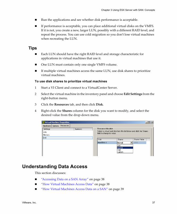
VMware, Inc. 37
Chapter 3 Using ESX Server with SAN: Concepts
! Run the applications and see whether disk performance is acceptable.
! If performance is acceptable, you can place additional virtual disks on the VMFS. If it is not, you create a new, larger LUN, possibly with a different RAID level, and repeat the process. You can use cold migration so you don�t lose virtual machines when recreating the LUN.
Tips ! Each LUN should have the right RAID level and storage characteristic for
applications in virtual machines that use it.
! One LUN must contain only one single VMFS volume.
! If multiple virtual machines access the same LUN, use disk shares to prioritize virtual machines.
To use disk shares to prioritize virtual machines
1 Start a VI Client and connect to a VirtualCenter Server.
2 Select the virtual machine in the inventory panel and choose Edit Settings from the right‐button menu.
3 Click the Resources tab, and then click Disk.
4 Right‐click the Shares column for the disk you want to modify, and select the desired value from the drop‐down menu.
Understanding Data AccessThis section discusses:
! �Accessing Data on a SAN Array� on page 38! �How Virtual Machines Access Data� on page 38! �How Virtual Machines Access Data on a SAN� on page 39
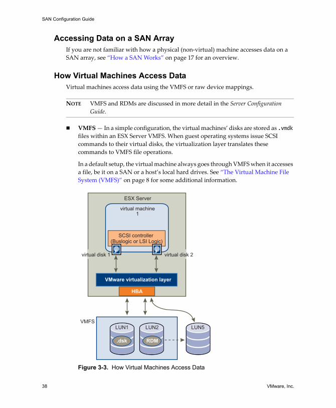
SAN Configuration Guide
38 VMware, Inc.
Accessing Data on a SAN Array If you are not familiar with how a physical (non‐virtual) machine accesses data on a SAN array, see �How a SAN Works� on page 17 for an overview.
How Virtual Machines Access DataVirtual machines access data using the VMFS or raw device mappings.
NOTE VMFS and RDMs are discussed in more detail in the Server Configuration Guide.
! VMFS � In a simple configuration, the virtual machines� disks are stored as .vmdk files within an ESX Server VMFS. When guest operating systems issue SCSI commands to their virtual disks, the virtualization layer translates these commands to VMFS file operations.
In a default setup, the virtual machine always goes through VMFS when it accesses a file, be it on a SAN or a host�s local hard drives. See �The Virtual Machine File System (VMFS)� on page 8 for some additional information.
Figure 3-3. How Virtual Machines Access Data
virtual machine1
VMFS
ESX Server
HBA
VMware virtualization layer
.dsk
LUN1 LUN2 LUN5
RDM
SCSI controller (Buslogic or LSI Logic)
virtual disk 2virtual disk 1
VMware, Inc. 39
Chapter 3 Using ESX Server with SAN: Concepts
! Raw device mapping (RDM) � An RDM is a mapping file inside the VMFS that acts as a proxy for a raw device. The RDM gives the guest operating system access to the raw device.
RDM is recommended when a virtual machine must interact with a real disk on the SAN. This is the case, for example, when you make disk array snapshots or, more rarely, if you have a large amount of data that you don�t want to move onto a virtual disk. It is also required for Microsoft Cluster Service setup. See the VMware document Setup for Microsoft Cluster Service for more information.
How Virtual Machines Access Data on a SANA virtual machine interacts with a SAN as follows:
1 When the guest operating system in a virtual machine needs to read or write to SCSI disk, it issues SCSI commands to the virtual disk.
2 Device drivers in the virtual machine�s operating system communicate with the virtual SCSI controllers. VMware ESX Server supports two types of virtual SCSI controllers: BusLogic and LSILogic.
3 The virtual SCSI Controller forwards the command to the VMkernel.
4 The VMkernel:
! Locates the file in the VMFS volume that corresponds to the guest virtual machine disk.
! Maps the requests for the blocks on the virtual disk to blocks on the appropriate physical device.
! Sends the modified I/O request from the device driver in the VMkernel to the physical HBA (host HBA).
5 The host HBA:
! Converts the request from its binary data form to the optical form required for transmission on the fiber optic cable.
! Packages the request according to the rules of the FC protocol.
! Transmits the request to the SAN.
6 Depending on which port the HBA uses to connect to the fabric, one of the SAN switches receives the request and routes it to the storage device that the host wants to access. From the host�s perspective, this storage device appears to be a specific disk, but it might be a logical device that corresponds to a physical device on the SAN. The switch must determine which physical device has been made available to the host for its targeted logical device.
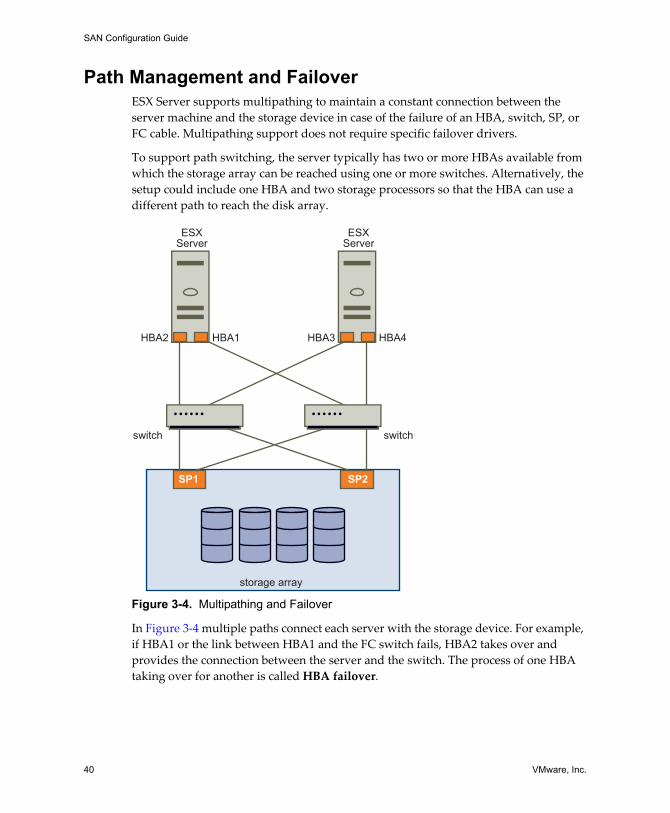
SAN Configuration Guide
40 VMware, Inc.
Path Management and FailoverESX Server supports multipathing to maintain a constant connection between the server machine and the storage device in case of the failure of an HBA, switch, SP, or FC cable. Multipathing support does not require specific failover drivers.
To support path switching, the server typically has two or more HBAs available from which the storage array can be reached using one or more switches. Alternatively, the setup could include one HBA and two storage processors so that the HBA can use a different path to reach the disk array.
Figure 3-4. Multipathing and Failover
In Figure 3‐4 multiple paths connect each server with the storage device. For example, if HBA1 or the link between HBA1 and the FC switch fails, HBA2 takes over and provides the connection between the server and the switch. The process of one HBA taking over for another is called HBA failover.
ESXServer
ESXServer
SP2
storage array
SP1
switch switch
HBA2 HBA1 HBA3 HBA4
VMware, Inc. 41
Chapter 3 Using ESX Server with SAN: Concepts
Similarly, if SP1 fails or the links between SP1 and the switches breaks, SP2 takes over and provides the connection between the switch and the storage device. This process is called SP failover. VMware ESX Server supports both HBA and SP failover with its multipathing capability.
You can choose a multipathing policy for your system, either Fixed or Most Recently Used. If the policy is Fixed, you can specify a preferred path. Each LUN (disk) that is visible to the ESX Server host can have its own path policy. See �Multipathing� on page 87 for information on viewing the current multipathing state and on setting the multipathing policy.
NOTE Virtual machine I/O might be delayed for at most sixty seconds while failover takes place, particularly on an active/passive array. This delay is necessary to allow the SAN fabric to stabilize its configuration after topology changes or other fabric events. In the case of an active/passive array with path policy Fixed, path thrashing may be a problem. See �Resolving Path Thrashing� on page 101.
Choosing Virtual Machine LocationsWhen you�re working on optimizing performance for your virtual machines, storage location is an important factor. There is always a trade‐off between expensive storage that offers high performance and high availability and storage with lower cost and lower performance. Storage can be divided into different tiers depending on a number of factors:
! High Tier � Offers high performance and high availability. May offer built‐in snapshots to facilitate backups and Point‐in‐Time (PiT) restorations. Supports replication, full SP redundancy, and fibre drives. Uses high cost spindles.
! Mid Tier � Offers mid‐range performance, lower availability, some SP redundancy, and SCSI drives. May offer snapshots. Uses medium cost spindles.
! Lower Tier � Offers low performance, little internal storage redundancy. Uses low end SCSI drives or SATA (serial low cost spindles).
Not all applications need to be on the highest performance, most available storage�at least not throughout their entire life cycle.
NOTE If you need some of the functionality of the high tier, such as snapshots, but don�t want to pay for it, you might be able to achieve some of the high‐performance characteristics in software. For example, you can create snapshots in software.
SAN Configuration Guide
42 VMware, Inc.
When you decide where to place a virtual machine, ask yourself these questions:
! How critical is the virtual machine?! What are its performance and availability requirements?! What are its point‐in‐time (PiT) restoration requirements?! What are its backup requirements?! What are its replication requirements?
A virtual machine might change tiers throughout its life cycle due to changes in criticality or changes in technology that push higher tier features to a lower tier. Criticality is relative, and might change for a variety of reasons, including changes in the organization, operational processes, regulatory requirements, disaster planning, and so on.
Designing for Server FailureThe RAID architecture of SAN storage inherently protects you from failure at the physical disk level. A dual fabric, with duplication of all fabric components, protects the SAN from most fabric failures. The final step in making your whole environment failure resistant is to protect against server failure. ESX Server systems failover options are briefly discussed in this section.
Using VMware HAVMware HA allows you to organize virtual machines into failover groups. When a host fails, all its virtual machines are immediately started on different hosts. HA requires SAN storage.
When a virtual machine is restored on a different host, it loses its memory state but its disk state is exactly as it was when the host failed (crash‐consistent failover). Shared storage (such as a SAN) is required for HA. See the Resource Management Guide for detailed information.
NOTE You must be licensed to use VMware HA.
Using Cluster ServicesServer clustering is a method of tying two or more servers together using a high‐speed network connection so that the group of servers functions as a single, logical server. If one of the servers fails, then the other servers in the cluster continue operating, picking up the operations performed by the failed server.
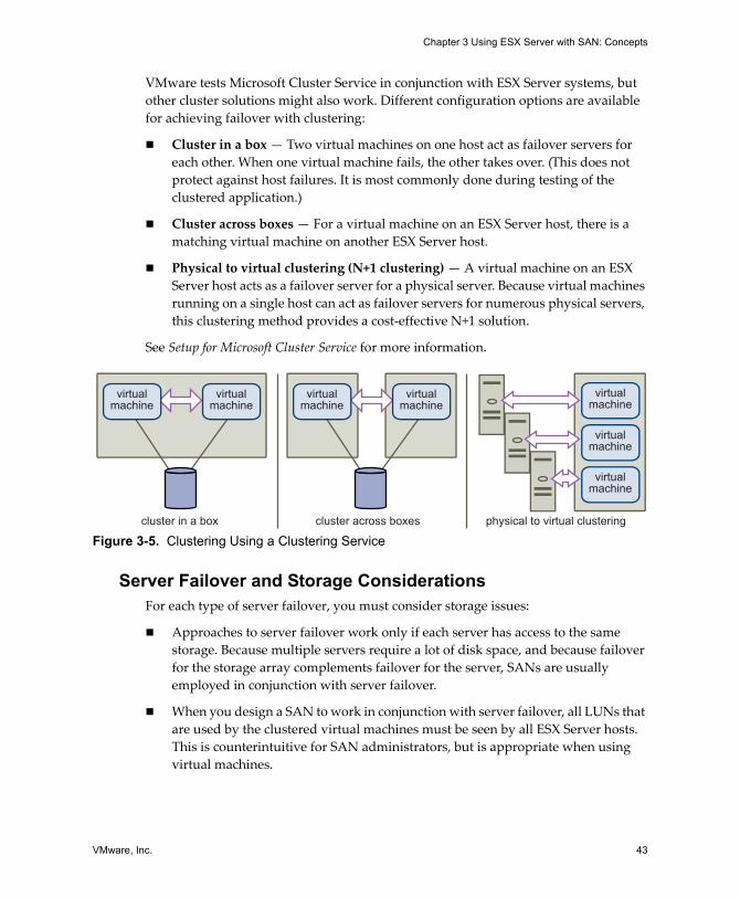
VMware, Inc. 43
Chapter 3 Using ESX Server with SAN: Concepts
VMware tests Microsoft Cluster Service in conjunction with ESX Server systems, but other cluster solutions might also work. Different configuration options are available for achieving failover with clustering:
! Cluster in a box � Two virtual machines on one host act as failover servers for each other. When one virtual machine fails, the other takes over. (This does not protect against host failures. It is most commonly done during testing of the clustered application.)
! Cluster across boxes � For a virtual machine on an ESX Server host, there is a matching virtual machine on another ESX Server host.
! Physical to virtual clustering (N+1 clustering) � A virtual machine on an ESX Server host acts as a failover server for a physical server. Because virtual machines running on a single host can act as failover servers for numerous physical servers, this clustering method provides a cost‐effective N+1 solution.
See Setup for Microsoft Cluster Service for more information.
Figure 3-5. Clustering Using a Clustering Service
Server Failover and Storage ConsiderationsFor each type of server failover, you must consider storage issues:
! Approaches to server failover work only if each server has access to the same storage. Because multiple servers require a lot of disk space, and because failover for the storage array complements failover for the server, SANs are usually employed in conjunction with server failover.
! When you design a SAN to work in conjunction with server failover, all LUNs that are used by the clustered virtual machines must be seen by all ESX Server hosts. This is counterintuitive for SAN administrators, but is appropriate when using virtual machines.
virtualmachine
virtualmachine
virtualmachine
virtualmachine
cluster in a box cluster across boxes physical to virtual clustering
virtualmachine
virtualmachine
virtualmachine
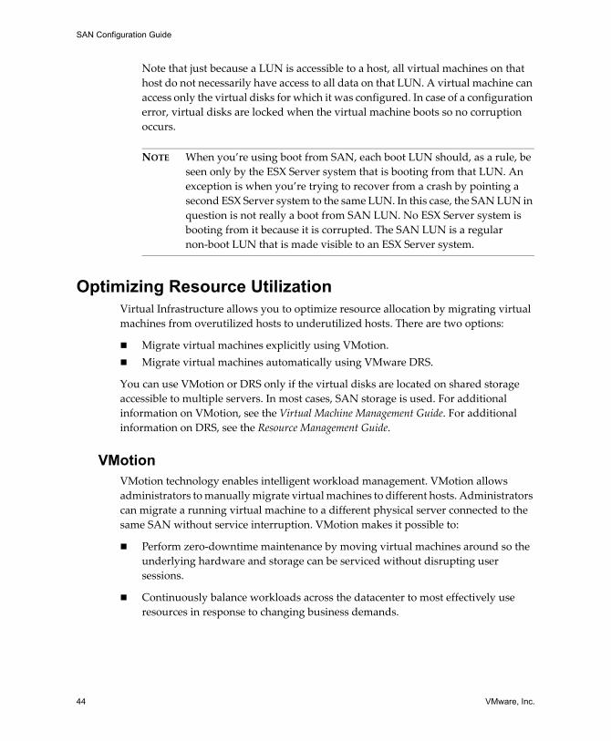
SAN Configuration Guide
44 VMware, Inc.
Note that just because a LUN is accessible to a host, all virtual machines on that host do not necessarily have access to all data on that LUN. A virtual machine can access only the virtual disks for which it was configured. In case of a configuration error, virtual disks are locked when the virtual machine boots so no corruption occurs.
NOTE When you�re using boot from SAN, each boot LUN should, as a rule, be seen only by the ESX Server system that is booting from that LUN. An exception is when you�re trying to recover from a crash by pointing a second ESX Server system to the same LUN. In this case, the SAN LUN in question is not really a boot from SAN LUN. No ESX Server system is booting from it because it is corrupted. The SAN LUN is a regular non‐boot LUN that is made visible to an ESX Server system.
Optimizing Resource UtilizationVirtual Infrastructure allows you to optimize resource allocation by migrating virtual machines from overutilized hosts to underutilized hosts. There are two options:
! Migrate virtual machines explicitly using VMotion.! Migrate virtual machines automatically using VMware DRS.
You can use VMotion or DRS only if the virtual disks are located on shared storage accessible to multiple servers. In most cases, SAN storage is used. For additional information on VMotion, see the Virtual Machine Management Guide. For additional information on DRS, see the Resource Management Guide.
VMotionVMotion technology enables intelligent workload management. VMotion allows administrators to manually migrate virtual machines to different hosts. Administrators can migrate a running virtual machine to a different physical server connected to the same SAN without service interruption. VMotion makes it possible to:
! Perform zero‐downtime maintenance by moving virtual machines around so the underlying hardware and storage can be serviced without disrupting user sessions.
! Continuously balance workloads across the datacenter to most effectively use resources in response to changing business demands.
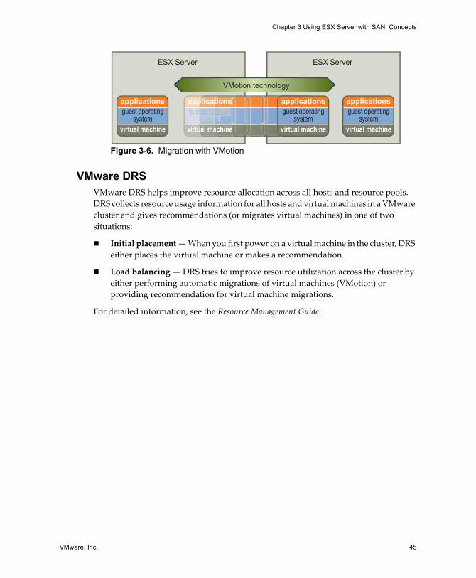
VMware, Inc. 45
Chapter 3 Using ESX Server with SAN: Concepts
Figure 3-6. Migration with VMotion
VMware DRSVMware DRS helps improve resource allocation across all hosts and resource pools. DRS collects resource usage information for all hosts and virtual machines in a VMware cluster and gives recommendations (or migrates virtual machines) in one of two situations:
! Initial placement � When you first power on a virtual machine in the cluster, DRS either places the virtual machine or makes a recommendation.
! Load balancing � DRS tries to improve resource utilization across the cluster by either performing automatic migrations of virtual machines (VMotion) or providing recommendation for virtual machine migrations.
For detailed information, see the Resource Management Guide.
ESX Server
VMotion technology
ESX Server
applications
virtual machine
guest operatingsystem
applications
virtual machine
guest operatingsystem
appappappplicatplicatplicatppp tionstionstionsttt sss
virtuvirtual maal mauu achineachineaa ee
guesguesguesst opest opest opesss eratingeratingeratingeeesystesystesystemmmememem
applications
virtual machine
guest operatingsystem

SAN Configuration Guide
46 VMware, Inc.

VMware, Inc. 47
CHAPTER 4 Requirements and Installation
This chapter presents hardware and system requirements for using ESX Server systems with SAN storage. The chapter consists of the following sections:
! �General ESX Server SAN Requirements� on page 48! �ESX Server Boot from SAN Requirements� on page 51! �SAN Installation Considerations� on page 52! �Installation and Setup Steps� on page 53
NOTE This chapter lists only the most basic requirements. Before you start setting up your system, consider reading the following chapters as well:
! Chapter 5, �Setting Up SAN Storage Devices with ESX Server,� on page 55
! Appendix A, �SAN Design Basics,� on page 113
SAN Configuration Guide
48 VMware, Inc.
General ESX Server SAN RequirementsIn preparation for configuring your SAN and setting up your ESX Server system to use SAN storage, review the following requirements and recommendations:
! Hardware and firmware. Only a limited number of SAN storage hardware and firmware combinations are supported in conjunction with ESX Server systems. See the SAN Compatibility Guide at http://www.vmware.com/pdf/esx_SAN_guide.pdf for an up‐to‐date list.
! Only one VMFS volume per LUN. Make sure that you configure your system to have only one VMFS volume per LUN. (In VMFS‐3, you no longer have to set accessibility.)
! Unless you�re using diskless servers, do not set up the diagnostic partition on a SAN LUN.
In the case of diskless servers that boot from SAN, a shared diagnostic partition is appropriate. See �Sharing Diagnostic Partitions� on page 97 for additional information on that special case.
! Using RDMs is recommended for access to any raw disk from an ESX Server 2.5 or later machine. For more information on RDMs, see the Server Configuration Guide.
! Multipathing. For multipathing to work properly, each LUN must present the same LUN number to all ESX Server hosts.
! Queue size. Make sure the BusLogic or LSILogic driver in the guest operating system specifies a big enough queue. You can set the queue depth for the physical HBA during system setup. For supported drivers, see the SAN Compatibility Guide.
! SCSI Timeout. On virtual machines running Microsoft Windows, consider increasing the value of the SCSI TimeoutValue parameter to allows Windows to better tolerate delayed I/O resulting from path failover. See �Setting Operating System Timeout� on page 96.
RestrictionsThe following restrictions apply when you use ESX Server with a SAN.
! ESX Server does not support FC connected tape devices. These devices can, however, be managed by the VMware Consolidated Backup proxy, which is discussed in the Virtual Machine Backup Guide.
! Virtual machine multipathing software cannot be used to perform I/O load balancing to a single physical LUN.
VMware, Inc. 49
Chapter 4 Requirements and Installation
! You cannot use virtual machine logical volume manager software to mirror virtual disks. Dynamic disks in a Microsoft Windows virtual machine are an exception but require special configuration.
Setting LUN AllocationsWhen setting LUN allocations, note the following points:
! Storage Provisioning � To ensure that the ESX Server system recognizes the LUNs at startup time, provision all LUNS to the appropriate HBAs before connecting the SAN to the ESX Server system.
NOTE Provisioning all LUNs to all ESX Server HBAs at the same time is recommended. HBA failover works only if all HBAs see the same LUNs.
! VMotion and VMware DRS � When you use VirtualCenter and VMotion or DRS, make sure that the LUNs for the virtual machines are provisioned to all ESX Server hosts. This provides the greatest freedom in moving virtual machines.
! Active/active versus active/passive arrays � When using VMotion or DRS with an active/passive SAN storage device, make sure that all ESX Server systems have consistent paths to all storage processors. Not doing so can cause path thrashing when a VMotion migration occurs. See �Resolving Path Thrashing� on page 101.
For active/passive storage arrays not listed in the SAN Compatibility Guide, VMware does not support storage port failover. In those cases, you must connect the server to the active port on the storage array. This configuration ensures that the LUNs are presented to the ESX Server host.
FC HBA SetupDuring FC HBA setup, consider the following points:
! HBA Default Settings � FC HBAs work correctly with the default configuration settings. Follow the configuration guidelines given by your storage array vendor.
NOTE For best results, use the same model of HBA within one server. Ensure that the firmware level on each HBA is the same within one server. Having both Emulex and QLogic HBAs in the same server to the same target is not supported.
! Static Load Balancing Across HBAs � Some ESX Server systems can be configured to load balance traffic across multiple HBAs to multiple LUNs with certain active/active arrays.
SAN Configuration Guide
50 VMware, Inc.
To do this, assign preferred paths to your LUNs so that your HBAs are being used evenly. For example, if you have two LUNs (A and B) and two HBAs (X and Y), you can set HBA X to be the preferred path for LUN A, and HBA Y as the preferred path for LUN B, thus maximizing utilization of your HBAs. Path policy must be set to Fixed for this case. See �To set the multipathing policy using a VI Client� on page 91.
! Setting the Timeout for Failover � The timeout value for detecting when a path fails is set in the HBA driver. Setting the timeout to 30 seconds ensures optimal performance and is highly recommended. To set the value, follow the instructions in �Setting the HBA Timeout for Failover� on page 95.
! Dedicated Adapter for Tape Drives � For best results, use a dedicated SCSI adapter for any tape drives that you are connecting to an ESX Server system. FC connected tape drives are not supported. Use the Consolidated Backup proxy, as discussed in the Virtual Machine Backup Guide.
For additional information on boot from SAN HBA setup, see Chapter 6, �Using Boot from SAN with ESX Server Systems,� on page 69.
RecommendationsThis section gives guidance on making decisions when setting up your environment with ESX Server hosts and a SAN.
! Use raw device mapping for a virtual disk of a virtual machine if you want to use some of the hardware snapshotting functions of the disk array, or if you want to access a disk from both a virtual machine and a physical machine in a cold standby host configuration for data LUNs.
! Use raw device mapping for the shared disks in a Microsoft Cluster Service setup. See the VMware document Setup for Microsoft Cluster Service for details.
! Allocate a large LUN for use by multiple virtual machines and set it up as a VMFS. You can then create or delete virtual machines dynamically without having to request additional disk space each time you add a virtual machine.
! If you want to move a virtual machine to a different host using VMotion, the LUNs that hold the virtual disks of the virtual machines must be masked so they are visible from all the hosts.
See Chapter 7, �Managing ESX Server Systems That Use SAN Storage,� on page 79 for additional recommendations and troubleshooting information.
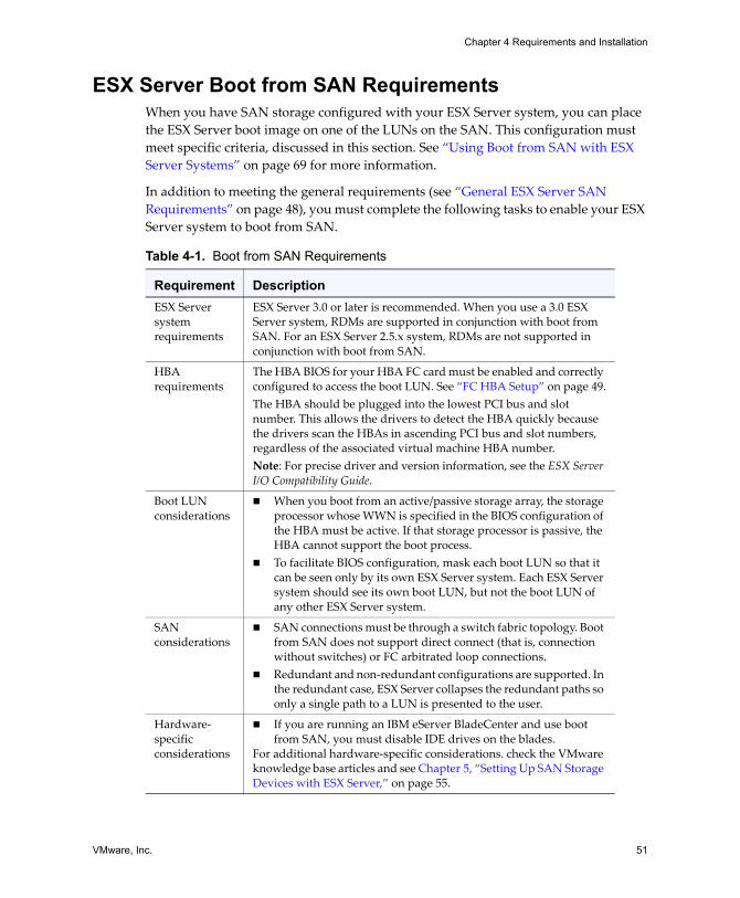
VMware, Inc. 51
Chapter 4 Requirements and Installation
ESX Server Boot from SAN RequirementsWhen you have SAN storage configured with your ESX Server system, you can place the ESX Server boot image on one of the LUNs on the SAN. This configuration must meet specific criteria, discussed in this section. See �Using Boot from SAN with ESX Server Systems� on page 69 for more information.
In addition to meeting the general requirements (see �General ESX Server SAN Requirements� on page 48), you must complete the following tasks to enable your ESX Server system to boot from SAN.
Table 4-1. Boot from SAN Requirements
Requirement DescriptionESX Server system requirements
ESX Server 3.0 or later is recommended. When you use a 3.0 ESX Server system, RDMs are supported in conjunction with boot from SAN. For an ESX Server 2.5.x system, RDMs are not supported in conjunction with boot from SAN.
HBA requirements
The HBA BIOS for your HBA FC card must be enabled and correctly configured to access the boot LUN. See �FC HBA Setup� on page 49.The HBA should be plugged into the lowest PCI bus and slot number. This allows the drivers to detect the HBA quickly because the drivers scan the HBAs in ascending PCI bus and slot numbers, regardless of the associated virtual machine HBA number.Note: For precise driver and version information, see the ESX Server I/O Compatibility Guide.
Boot LUN considerations
! When you boot from an active/passive storage array, the storage processor whose WWN is specified in the BIOS configuration of the HBA must be active. If that storage processor is passive, the HBA cannot support the boot process.
! To facilitate BIOS configuration, mask each boot LUN so that it can be seen only by its own ESX Server system. Each ESX Server system should see its own boot LUN, but not the boot LUN of any other ESX Server system.
SAN considerations
! SAN connections must be through a switch fabric topology. Boot from SAN does not support direct connect (that is, connection without switches) or FC arbitrated loop connections.
! Redundant and non‐redundant configurations are supported. In the redundant case, ESX Server collapses the redundant paths so only a single path to a LUN is presented to the user.
Hardware‐specific considerations
! If you are running an IBM eServer BladeCenter and use boot from SAN, you must disable IDE drives on the blades.
For additional hardware‐specific considerations. check the VMware knowledge base articles and see Chapter 5, �Setting Up SAN Storage Devices with ESX Server,� on page 55.
SAN Configuration Guide
52 VMware, Inc.
SAN Installation ConsiderationsInstalling a SAN requires careful attention to details and an overall plan that addresses all the hardware, software, storage, and applications issues and their interactions as all the pieces are integrated.
RequirementsTo integrate all components of the SAN, you must meet the vendor�s hardware and software compatibility requirements, including the following:
! HBA (firmware version, driver version, and patch list)! Switch (firmware)! Storage (firmware, host personality firmware, and patch list)
SAN SetupWhen you�re ready to set up the SAN, complete these tasks.
To prepare the SAN
1 Assemble and cable together all hardware components and install the corresponding software.
a Check the versions.
b Set up the HBA.
c Set up the storage array.
2 Change any configuration settings that might be required.
3 Test the integration.
During integration testing, test all the operational processes for the SAN environment. These include normal production processing, failure mode testing, backup functions, and so forth.
4 Establish a baseline of performance for each component and for the entire SAN.
Each baseline provides a measurement metric for future changes and tuning. See �Optimizing SAN Storage Performance� on page 98 and �Resolving Performance Issues� on page 100 for additional information.
5 Document the SAN installation and all operational procedures.
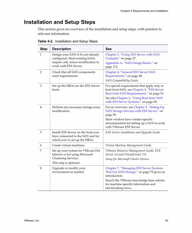
VMware, Inc. 53
Chapter 4 Requirements and Installation
Installation and Setup StepsThis section gives an overview of the installation and setup steps, with pointers to relevant information.
Table 4-2. Installation and Setup Steps
Step Description See1 Design your SAN if it�s not already
configured. Most existing SANs require only minor modification to work with ESX Server.
Chapter 3, �Using ESX Server with SAN: Concepts,� on page 27.Appendix A, �SAN Design Basics,� on page 113.
2 Check that all SAN components meet requirements.
Chapter 4, �General ESX Server SAN Requirements,� on page 48.SAN Compatibility Guide.
3 Set up the HBAs for the ESX Server hosts.
For special requirements that apply only to boot from SAN, see Chapter 4, �ESX Server Boot from SAN Requirements,� on page 51.See also Chapter 6, �Using Boot from SAN with ESX Server Systems,� on page 69.
4 Perform any necessary storage array modification.
For an overview, see Chapter 5, �Setting Up SAN Storage Devices with ESX Server,� on page 55.Most vendors have vendor‐specific documentation for setting up a SAN to work with VMware ESX Server.
5 Install ESX Server on the hosts you have connected to the SAN and for which you�ve set up the HBAs.
ESX Server Installation and Upgrade Guide.
6 Create virtual machines. Virtual Machine Management Guide.
7 Set up your system for VMware HA failover or for using Microsoft Clustering Services.This step is optional.
VMware Resource Management Guide: ESX Server 3.0 and VirtualCenter 2.0. Setup for Microsoft Cluster Service.
8 Upgrade or modify your environment as needed.
Chapter 7, �Managing ESX Server Systems That Use SAN Storage,� on page 79 gives an introduction. Search the VMware knowledge base articles for machine‐specific information and late‐breaking news.

SAN Configuration Guide
54 VMware, Inc.
VMware, Inc. 55
CHAPTER 5 Setting Up SAN Storage Devices with ESX Server
This chapter discusses many of the storage devices supported in conjunction with VMware ESX Server. For each device, it lists the major known potential issues, points to vendor‐specific information (if available), and includes information from VMware knowledge base articles.
NOTE Because the information in this document is updated only with each release, new information might already be available when you receive this document. Consult the most recent ESX Server SAN Compatibility Guide, check with your storage array vendor, and explore the VMware knowledge base articles.
This chapter discusses the following topics:
! �Introduction� on page 56! �General Considerations� on page 57! �EMC CLARiiON Storage Systems� on page 58! �EMC Symmetrix Storage Systems� on page 59! �IBM TotalStorage DS4000 Storage Systems� on page 60! �IBM TotalStorage 8000� on page 64! �HP StorageWorks Storage Systems� on page 64! �Hitachi Data Systems Storage� on page 67! �Network Appliance Storage� on page 67
SAN Configuration Guide
56 VMware, Inc.
IntroductionVMware ESX Server supports a variety of SAN storage arrays in different configurations. Not all storage devices are certified for all features and capabilities of ESX Server, and vendors might have specific positions of support with regard to ESX Server. Check http://www.vmware.com/pdf/esx_SAN_guide.pdf for the latest information regarding supported storage arrays.
TestingVMware tests ESX Server with storage arrays in the following configurations:
! Basic Connectivity � Tests whether ESX Server can recognize and interoperate with the storage array. This configuration does not allow for multipathing or any type of failover.
! HBA Failover � In this configuration, the server is equipped with multiple HBAs connecting to one or more SAN switches. The server is robust to HBA and switch failure only.
! Storage Port Failover � In this configuration, the server is attached to multiple storage ports and is robust to storage port failures and switch failures.
! Boot From SAN � In this configuration, the ESX Server host boots from a LUN configured on the SAN rather than from the server itself.
! Direct connect � In this configuration, the server connects to the array without using switches, using only an FC cable. For all other tests, a fabric connection is used. FC Arbitrated Loop (AL) is not supported.
! Clustering � In this configuration, the system is tested with Microsoft Cluster Service running in the virtual machine. See the Setup for Microsoft Cluster Service document included in this documentation set for information.
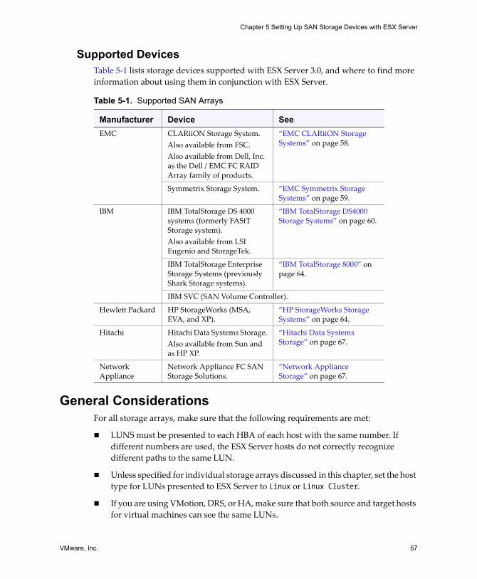
VMware, Inc. 57
Chapter 5 Setting Up SAN Storage Devices with ESX Server
Supported DevicesTable 5‐1 lists storage devices supported with ESX Server 3.0, and where to find more information about using them in conjunction with ESX Server.
General ConsiderationsFor all storage arrays, make sure that the following requirements are met:
! LUNS must be presented to each HBA of each host with the same number. If different numbers are used, the ESX Server hosts do not correctly recognize different paths to the same LUN.
! Unless specified for individual storage arrays discussed in this chapter, set the host type for LUNs presented to ESX Server to Linux or Linux Cluster.
! If you are using VMotion, DRS, or HA, make sure that both source and target hosts for virtual machines can see the same LUNs.
Table 5-1. Supported SAN Arrays
Manufacturer Device SeeEMC CLARiiON Storage System.
Also available from FSC.Also available from Dell, Inc. as the Dell / EMC FC RAID Array family of products.
�EMC CLARiiON Storage Systems� on page 58.
Symmetrix Storage System. �EMC Symmetrix Storage Systems� on page 59.
IBM IBM TotalStorage DS 4000 systems (formerly FAStT Storage system). Also available from LSI Eugenio and StorageTek.
�IBM TotalStorage DS4000 Storage Systems� on page 60.
IBM TotalStorage Enterprise Storage Systems (previously Shark Storage systems).
�IBM TotalStorage 8000� on page 64.
IBM SVC (SAN Volume Controller).
Hewlett Packard HP StorageWorks (MSA, EVA, and XP).
�HP StorageWorks Storage Systems� on page 64.
Hitachi Hitachi Data Systems Storage.Also available from Sun and as HP XP.
�Hitachi Data Systems Storage� on page 67.
Network Appliance
Network Appliance FC SAN Storage Solutions.
�Network Appliance Storage� on page 67.
SAN Configuration Guide
58 VMware, Inc.
SAN administrators might find it counterintuitive to have multiple hosts see the same LUNs because they might be concerned about data corruption. However, VMFS prevents multiple virtual machines from writing to the same file at the same time, so provisioning the LUNs to all required ESX Server system is appropriate.
EMC CLARiiON Storage SystemsYour EMC CLARiiON storage systems work with ESX Server machines in SAN configurations. Basic configuration steps include:
1 Installing and configuring your storage device.
2 Configuring zoning at the switch level.
3 Creating RAID groups.
4 Creating and binding LUNs.
5 Registering the servers connected to the SAN.
6 Creating storage groups that contain the servers and LUNs.
Use the EMC software to perform configuration. See the EMC documentation for information.
NOTE This is an active/passive disk array, so related issues described elsewhere in this document apply.
To avoid the possibility of path thrashing, the default multipathing policy is Most Recently Used, not Fixed. The ESX Server system sets the default policy when it identifies the array. See �Resolving Path Thrashing� on page 101.
NOTE To use boot from SAN, make sure that the active storage processor is chosen for the boot LUN�s target in the HBA BIOS.
EMC CLARiiON AX100 The following points are of interest when you work with an EMC CLARiiON storage array.
Raw Device MappingOn EMC CLARiiON AX100 systems, raw device mapping is supported only if you use the Navisphere Management Suite for SAN administration. Navilight is not guaranteed to work properly.

VMware, Inc. 59
Chapter 5 Setting Up SAN Storage Devices with ESX Server
Note that to use RDMs successfully, a given LUN needs to be exported with the same LUN ID to every ESX Server host in the cluster. The AX100 does not do this by default.
AX100 Display Problems with Inactive ConnectionsWhen using an AX100 FC storage device directly connected to an ESX Server systems, you must verify that all connections are operational and deregister any connections that are no longer in use. If you donʹt, ESX Server cannot discover new LUNs or paths.
Consider the following scenario:
1 An ESX Server system is directly connected to an AX100 storage device. The ESX Server has two FC HBAs. One of the HBAs was previously registered with the storage array and its LUNs were configured, but the connections are now inactive.
2 When you connect the second HBA in the ESX Server host to the AX100 and register it, the ESX Server host correctly shows the array as having an active connection. However, none of the LUNS that were previously configured to the ESX Server host are visible, even after repeated rescans.
To resolve this issue, remove the inactive HBA, deregister the connection to the inactive HBA, or make all inactive connections active. This causes only active HBAs to be in the storage group. After this change, rescan to add the configured LUNs.
Automatic Volume ResignaturingAutomatic volume resignaturing is not supported for AX100 storage devices. See �VMFS Volume Resignaturing� on page 108 for information on resignaturing.
EMC Symmetrix Storage SystemsThe following settings are required for ESX Server operations on the Symmetrix networked storage system:
! Common serial number (C)! Auto negotiation (EAN) enabled! Fibrepath enabled on this port (VCM)! SCSI 3 (SC3)! Unique world wide name (UWN)! SPC‐2 (Decal) (SPC2) SPC‐2 flag set
You configure the storage array using EMC software. Refer to your EMC documentation for information.
SAN Configuration Guide
60 VMware, Inc.
NOTE The ESX Server host considers any LUNs from a Symmetrix storage array that have a capacity of 50MB or less as management LUNs. These LUNs are also known as pseudo or gatekeeper LUNs. These LUNs appear in the EMC Symmetrix Management Interface and should not be used to hold data.
IBM TotalStorage DS4000 Storage SystemsIBM TotalStorage DS4000 systems used to be called IBM FAStT. A number of storage array vendors (including LSI and StorageTek) make SAN storage arrays that are compatible with the DS4000.
See the IBM Redbook, Implementing VMware ESX Server with IBM TotalStorage FAStT at http://www.redbooks.ibm.com/redbooks/pdfs/sg246434.pdf for a detailed discussion. This section summarizes configuring your IBM TotalStorage Storage System for using SAN and Microsoft Clustering Service. See the Setup for Microsoft Cluster Service document for additional information.
In addition to normal configuration steps for your IBM TotalStorage storage system, perform the tasks described in the following sections:
! �Configuring the Hardware for SAN Failover with DS4000 Storage Servers� on page 60
! �Verifying the Storage Processor Port Configuration� on page 61! �Disabling Auto Volume Transfer� on page 62! �Configuring Storage Processor Sense Data� on page 63
You must also make sure that multipathing policy is set to Most Recently Used. See �Viewing the Current Multipathing State� on page 88.
Configuring the Hardware for SAN Failover with DS4000 Storage Servers
To set up a highly available SAN failover configuration with DS4000 storage models equipped with two storage processors, you need the following hardware components:
! Two FC HBAs, such as QLogic or Emulex, on each ESX Server machine.! Two FC switches connecting the HBAs to the SAN (for example, SW1 and SW2). ! Two SPs (for example, SPA and SPB).
Each SP must have at least two ports connected to the SAN.
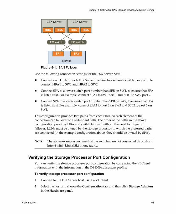
VMware, Inc. 61
Chapter 5 Setting Up SAN Storage Devices with ESX Server
Figure 5-1. SAN Failover
Use the following connection settings for the ESX Server host:
! Connect each HBA on each ESX Server machine to a separate switch. For example, connect HBA1 to SW1 and HBA2 to SW2.
! Connect SPA to a lower switch port number than SPB on SW1, to ensure that SPA is listed first. For example, connect SPA1 to SW1 port 1 and SPB1 to SW2 port 2.
! Connect SPA to a lower switch port number than SPB on SW2, to ensure that SPA is listed first. For example, connect SPA2 to port 1 on SW2 and SPB2 to port 2 on SW1.
This configuration provides two paths from each HBA, so each element of the connection can fail over to a redundant path. The order of the paths in the above configuration provides HBA and switch failover without the need to trigger SP failover. LUNs must be owned by the storage processor to which the preferred paths are connected (in the example configuration above, they should be owned by SPA).
NOTE The above examples assume that the switches are not connected through an Inter‐Switch Link (ISL) in one fabric.
Verifying the Storage Processor Port ConfigurationYou can verify the storage processor port configuration by comparing the VI Client information with the information in the DS4000 subsystem profile.
To verify storage processor port configuration
1 Connect to the ESX Server host using a VI Client.
2 Select the host and choose the Configuration tab, and then click Storage Adapters in the Hardware panel.
storage
ESX Server ESX Server
SP1 SP2
FC switchFC switch
HBAHBA HBAHBA
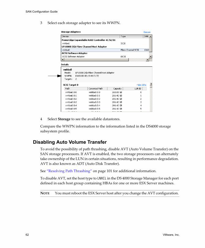
SAN Configuration Guide
62 VMware, Inc.
3 Select each storage adapter to see its WWPN.
4 Select Storage to see the available datastores.
Compare the WWPN information to the information listed in the DS4000 storage subsystem profile.
Disabling Auto Volume Transfer To avoid the possibility of path thrashing, disable AVT (Auto Volume Transfer) on the SAN storage processors. If AVT is enabled, the two storage processors can alternately take ownership of the LUN in certain situations, resulting in performance degradation. AVT is also known as ADT (Auto Disk Transfer).
See �Resolving Path Thrashing� on page 101 for additional information.
To disable AVT, set the host type to LNXCL in the DS 4000 Storage Manager for each port defined in each host group containing HBAs for one or more ESX Server machines.
NOTE You must reboot the ESX Server host after you change the AVT configuration.
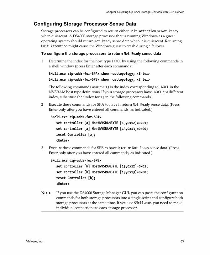
VMware, Inc. 63
Chapter 5 Setting Up SAN Storage Devices with ESX Server
Configuring Storage Processor Sense DataStorage processors can be configured to return either Unit Attention or Not Ready when quiescent. A DS4000 storage processor that is running Windows as a guest operating system should return Not Ready sense data when it is quiescent. Returning Unit Attention might cause the Windows guest to crash during a failover.
To configure the storage processors to return Not Ready sense data
1 Determine the index for the host type LNXCL by using the following commands in a shell window (press Enter after each command):
SMcli.exe <ip-addr-for-SPA> show hosttopology; <Enter>
SMcli.exe <ip-addr-for-SPB> show hosttopology; <Enter>
The following commands assume 13 is the index corresponding to LNXCL in the NVSRAM host type definitions. If your storage processors have LNXCL at a different index, substitute that index for 13 in the following commands.
2 Execute these commands for SPA to have it return Not Ready sense data. (Press Enter only after you have entered all commands, as indicated.)
SMcli.exe <ip-addr-for-SPA>
set controller [a] HostNVSRAMBYTE [13,0x12]=0x01;
set controller [a] HostNVSRAMBYTE [13,0x13]=0x00;
reset Controller [a];
<Enter>
3 Execute these commands for SPB to have it return Not Ready sense data. (Press Enter only after you have entered all commands, as indicated.)
SMcli.exe <ip-addr-for-SPB>
set controller [b] HostNVSRAMBYTE [13,0x12]=0x01;
set controller [b] HostNVSRAMBYTE [13,0x13]=0x00;
reset Controller [b];
<Enter>
NOTE If you use the DS4000 Storage Manager GUI, you can paste the configuration commands for both storage processors into a single script and configure both storage processors at the same time. If you use SMcli.exe, you need to make individual connections to each storage processor.
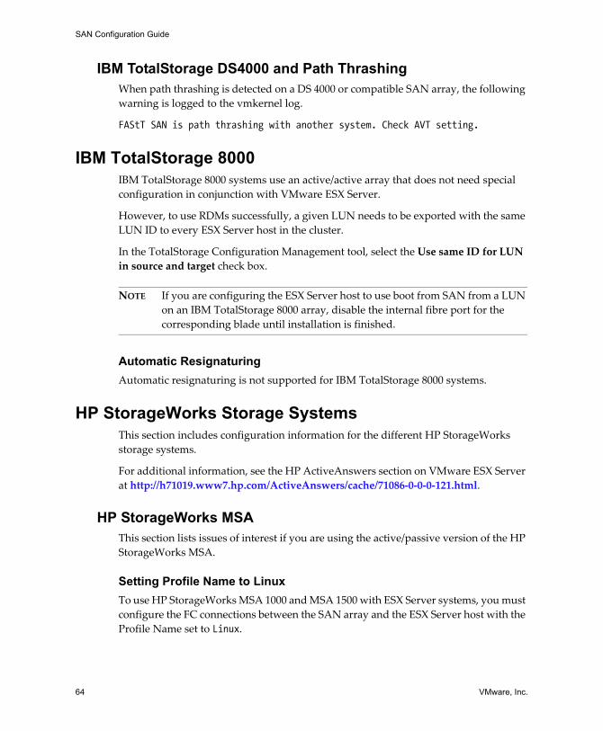
SAN Configuration Guide
64 VMware, Inc.
IBM TotalStorage DS4000 and Path ThrashingWhen path thrashing is detected on a DS 4000 or compatible SAN array, the following warning is logged to the vmkernel log.
FAStT SAN is path thrashing with another system. Check AVT setting.
IBM TotalStorage 8000IBM TotalStorage 8000 systems use an active/active array that does not need special configuration in conjunction with VMware ESX Server.
However, to use RDMs successfully, a given LUN needs to be exported with the same LUN ID to every ESX Server host in the cluster.
In the TotalStorage Configuration Management tool, select the Use same ID for LUN in source and target check box.
NOTE If you are configuring the ESX Server host to use boot from SAN from a LUN on an IBM TotalStorage 8000 array, disable the internal fibre port for the corresponding blade until installation is finished.
Automatic ResignaturingAutomatic resignaturing is not supported for IBM TotalStorage 8000 systems.
HP StorageWorks Storage SystemsThis section includes configuration information for the different HP StorageWorks storage systems.
For additional information, see the HP ActiveAnswers section on VMware ESX Server at http://h71019.www7.hp.com/ActiveAnswers/cache/71086‐0‐0‐0‐121.html.
HP StorageWorks MSA This section lists issues of interest if you are using the active/passive version of the HP StorageWorks MSA.
Setting Profile Name to LinuxTo use HP StorageWorks MSA 1000 and MSA 1500 with ESX Server systems, you must configure the FC connections between the SAN array and the ESX Server host with the Profile Name set to Linux.
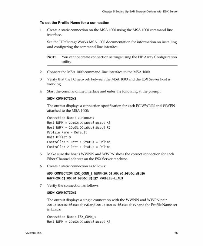
VMware, Inc. 65
Chapter 5 Setting Up SAN Storage Devices with ESX Server
To set the Profile Name for a connection
1 Create a static connection on the MSA 1000 using the MSA 1000 command line interface.
See the HP StorageWorks MSA 1000 documentation for information on installing and configuring the command line interface.
NOTE You cannot create connection settings using the HP Array Configuration utility.
2 Connect the MSA 1000 command‐line interface to the MSA 1000.
3 Verify that the FC network between the MSA 1000 and the ESX Server host is working.
4 Start the command line interface and enter the following at the prompt:
SHOW CONNECTIONS
The output displays a connection specification for each FC WWNN and WWPN attached to the MSA 1000:
Connection Name: <unknown>Host WWNN = 20:02:00:a0:b8:0c:d5:56 Host WWPN = 20:03:00:a0:b8:0c:d5:57Profile Name = Default Unit Offset 0 Controller 1 Port 1 Status = Online Controller 2 Port 1 Status = Online
5 Make sure the host�s WWNN and WWPN show the correct connection for each Fiber Channel adapter on the ESX Server machine.
6 Create a static connection as follows:
ADD CONNECTION ESX_CONN_1 WWNN=20:02:00:a0:b8:0c:d5:56 WWPN=20:03:00:a0:b8:0c:d5:57 PROFILE=LINUX
7 Verify the connection as follows:
SHOW CONNECTIONS
The output displays a single connection with the WWNN and WWPN pair 20:02:00:a0:b8:0c:d5:56 and 20:03:00:a0:b8:0c:d5:57 and the Profile Name set to Linux:
Connection Name: ESX_CONN_1 Host WWNN = 20:02:00:a0:b8:0c:d5:56
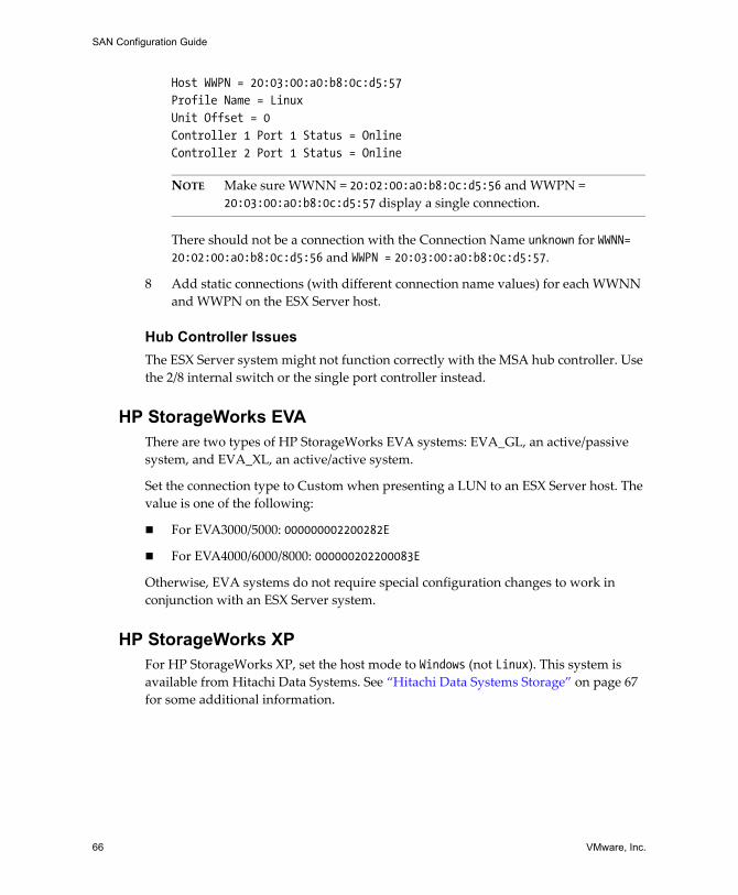
SAN Configuration Guide
66 VMware, Inc.
Host WWPN = 20:03:00:a0:b8:0c:d5:57 Profile Name = Linux Unit Offset = 0 Controller 1 Port 1 Status = Online Controller 2 Port 1 Status = Online
NOTE Make sure WWNN = 20:02:00:a0:b8:0c:d5:56 and WWPN = 20:03:00:a0:b8:0c:d5:57 display a single connection.
There should not be a connection with the Connection Name unknown for WWNN= 20:02:00:a0:b8:0c:d5:56 and WWPN = 20:03:00:a0:b8:0c:d5:57.
8 Add static connections (with different connection name values) for each WWNN and WWPN on the ESX Server host.
Hub Controller IssuesThe ESX Server system might not function correctly with the MSA hub controller. Use the 2/8 internal switch or the single port controller instead.
HP StorageWorks EVAThere are two types of HP StorageWorks EVA systems: EVA_GL, an active/passive system, and EVA_XL, an active/active system.
Set the connection type to Custom when presenting a LUN to an ESX Server host. The value is one of the following:
! For EVA3000/5000: 000000002200282E
! For EVA4000/6000/8000: 000000202200083E
Otherwise, EVA systems do not require special configuration changes to work in conjunction with an ESX Server system.
HP StorageWorks XPFor HP StorageWorks XP, set the host mode to Windows (not Linux). This system is available from Hitachi Data Systems. See �Hitachi Data Systems Storage� on page 67 for some additional information.
VMware, Inc. 67
Chapter 5 Setting Up SAN Storage Devices with ESX Server
Hitachi Data Systems Storage This section introduces setup for Hitachi Data Systems storage. This storage solution is also available from Sun and as HP XP storage.
! LUN Masking � To mask LUNs on an ESX Server host, use the HDS Storage Navigator software for best results.
! Microcode and Configurations � Check with your HDS representative for exact configurations and microcode levels needed for interoperability with ESX Server. If your microcode is not supported, interaction with ESX Server is usually not possible.
! Modes � The modes you set depend on the model you are using:
! 9900 and 9900v uses Netware host mode.
! 9500v series uses Hostmode1: standard and Hostmode2: SUN Cluster.
Network Appliance StorageThe following tasks are required for configuring a Network Appliance storage device.
Set LUN Type and Initiator Group TypeYou must set the appropriate LUN type and initiator group type for the storage array:
! LUN type � VMware (if VMware type is not available, use Linux)
! Initiator group type � VMware (if type VMware is not available, use Linux)
Provision StorageYou must provision storage.
To provision storage from a Network Appliance storage device
1 Using CLI or the FilerView GUI, create an Aggregate if required.
aggr create <vmware-aggr> <number of disks>
2 Create a Flexible Volume.
vol create <aggregate name> <volume size>
3 Create a Qtree to store each LUN.
qtree create <path>
4 Create a LUN.
SAN Configuration Guide
68 VMware, Inc.
lun create -s <size> -t vmware <path>
5 Create an initiator group.
igroup create -f -t vmware <igroup name>
6 Map the LUN to the initiator group you just created.
lun map (<path>) <igroup name> <LUN ID>
For additional information on using Network Appliance Storage with VMware technology, see the following Network Appliance documents:
! Network Appliance & VMware ESX Server: Instantaneous Backup & Recovery with NetApp Snapshot Technology at http://www.netapp.com/library/tr/3428.pdf.
! Technical Case Study: Using a Network Appliance SAN with VMware to Facilitate Storage and Server Consolidation at http://www.netapp.com/library/tr/3401.pdf.
VMware, Inc. 69
CHAPTER 6 Using Boot from SAN with ESX Server Systems
This chapter discusses benefits of boot from SAN and describes the tasks you need to perform if you plan to have the ESX Server boot image stored on a SAN LUN.
NOTE Skip this chapter if you do not plan to have your ESX Server host boot from a SAN.
The chapter discusses the following topics:
! �Benefits of Boot from SAN� on page 71! �Preparing to Install for Boot from SAN� on page 71! �Setting Up the FC HBA for Boot from SAN� on page 74
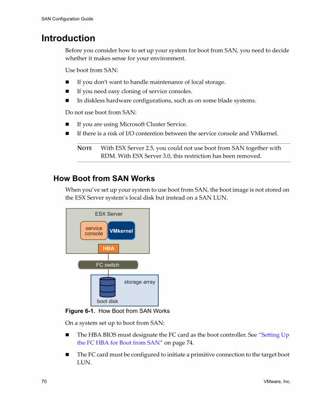
SAN Configuration Guide
70 VMware, Inc.
IntroductionBefore you consider how to set up your system for boot from SAN, you need to decide whether it makes sense for your environment.
Use boot from SAN:
! If you don�t want to handle maintenance of local storage. ! If you need easy cloning of service consoles.! In diskless hardware configurations, such as on some blade systems.
Do not use boot from SAN:
! If you are using Microsoft Cluster Service.! If there is a risk of I/O contention between the service console and VMkernel.
NOTE With ESX Server 2.5, you could not use boot from SAN together with RDM. With ESX Server 3.0, this restriction has been removed.
How Boot from SAN WorksWhen you�ve set up your system to use boot from SAN, the boot image is not stored on the ESX Server system�s local disk but instead on a SAN LUN.
Figure 6-1. How Boot from SAN Works
On a system set up to boot from SAN:
! The HBA BIOS must designate the FC card as the boot controller. See �Setting Up the FC HBA for Boot from SAN� on page 74.
! The FC card must be configured to initiate a primitive connection to the target boot LUN.
storage array
boot disk
ESX Server
FC switch
HBA
serviceconsole VMkernel
VMware, Inc. 71
Chapter 6 Using Boot from SAN with ESX Server Systems
Benefits of Boot from SANIn a boot from SAN environment, the operating system is installed on one or more LUNs in the SAN array. The servers are then informed about the boot image location. When the servers are started, they boot from the LUNs on the SAN array.
NOTE When you use boot from SAN in conjunction with a VMware ESX Server system, each server must have its own boot LUN.
Booting from a SAN provides numerous benefits, including:
! Cheaper servers � Servers can be more dense and run cooler without internal storage.
! Easier server replacement � You can replace servers and have the new server point to the old boot location.
! Less wasted space.
! Easier backup processes � The system boot images in the SAN can be backed up as part of the overall SAN backup procedures.
! Improved management � Creating and managing the operating system image is easier and more efficient.
Preparing to Install for Boot from SANIn addition to the general ESX Server with SAN configuration tasks, you must also complete the following tasks to enable your ESX Server host to boot from SAN.
1 Ensuring the configuration settings meet the basic boot from SAN requirements. See �ESX Server Boot from SAN Requirements� on page 51.
2 Preparing the hardware elements. This includes your HBA, network devices, and storage system. Refer to the product documentation for each device. See also �Setting Up the FC HBA for Boot from SAN� on page 74.
3 Configuring LUN masking on your SAN to ensure that each ESX Server host has a dedicated LUN for the boot partitions. The boot LUN must be dedicated to a single server.
4 Choosing the location for the diagnostic partition. Diagnostic partitions can be put on the same LUN as the boot partition. Core dumps are stored in diagnostic partitions. See �Sharing Diagnostic Partitions� on page 97.
The rest of this section lists the tasks you need to complete before you can successfully boot your ESX Server machine from SAN.
SAN Configuration Guide
72 VMware, Inc.
Before You Begin1 Review the recommendations or sample setups for the type of setup you want:
! Single or redundant paths to the boot LUN.
! FC switch fabric.
! Any specific recommendations that apply to the type of storage array you have.
2 Review restrictions and requirements including:
! Boot‐from‐SAN restrictions.
! The vendorʹs recommendation for the storage array to be used for booting from SAN.
! The vendorʹs recommendation for the server booting from SAN.
3 Find the WWN for the boot path HBA using one of the following methods:
! Go into the FC HBA BIOS upon boot.
! Find the WWN on the physical card. It is similar to a MAC address.
LUN Masking in Boot from SAN ModeProper LUN masking is critical in boot from SAN mode.
! Each server may see only its own boot LUN, not the boot LUNs of other servers.
! Multiple servers can share a diagnostic partition. You can use LUN masking to achieve this. See �Sharing Diagnostic Partitions� on page 97.
Preparing the SANThis section lists the steps for preparing the SAN storage array for boot from SAN. Steps 3‐7 are specific to boot from SAN, while steps 1 and 2 are not.
1 Connect the FC and Ethernet cables, referring to any cabling guide that applies to your setup. Check the FC switch wiring, if there is any.
2 Configure the storage array.
a From the SAN storage array, make the ESX Server host visible to the SAN. This is often referred to as creating an object.
b From the SAN storage array, set up the ESX Server host to have the WWPNs of the host�s FC adapters as port names or node names.
c Create LUNs.
VMware, Inc. 73
Chapter 6 Using Boot from SAN with ESX Server Systems
d Assign LUNs.
e Record the IP addresses of the FC switches and storage arrays.
f Record the WWPN for each storage processor and host adapter involved.
CAUTION If you use scripted installation to install ESX Server in boot from SAN mode, you need to take special steps to avoid unintended data loss. For more information, see VMware knowledge base article 1540 at http://www.vmware.com/support/kb/enduser/std_adp.php?p_faqid=1540.
3 Configure the HBA BIOS for boot from SAN, as discussed in the following sections:
! �Setting Up the QLogic FC HBA for Boot from SAN� on page 74.
! �Setting Up the Emulex FC HBA for Boot from SAN� on page 76
4 Boot your ESX Server system from the ESX Server installation CD. See the Installation Guide for additional information.
The QLogic BIOS uses a search list of paths (wwpn:lun) to locate a boot image. If one of the wwpn:lun paths is associated with a passive path (as could be the case, for example, with CLARiiON or IBM TotalStorage DS 4000 systems) the BIOS stays with the passive path and does not locate an active path. If you are booting your ESX Server system from a SAN LUN, the boot fails while the host tries to access the passive path.
Minimizing the Number of InitiatorsBe sure the zone contains the minimum number of host and storage ports possible. The Emulex and QLogic BIOS may become unresponsive if there are several other initiators in the same zone and you try to select a boot LUN.
For example, if there are fifteen initiators and four Symmetrix ports in one zone, you may not be able to select a boot device from either the Emulex or QLogic BIOS because it becomes unresponsive. If you zone the two host ports to see only the four storage ports, selecting a boot LUN becomes possible.
SAN Configuration Guide
74 VMware, Inc.
Setting Up the FC HBA for Boot from SANThis section discusses how to set up the HBAs:
! �Setting Up the QLogic FC HBA for Boot from SAN� below! �Setting Up the Emulex FC HBA for Boot from SAN� on page 76
Setting Up the QLogic FC HBA for Boot from SANConfiguring the QLogic HBA BIOS to boot ESX Server from SAN includes the following tasks discussed below:
! Enabling the QLogic HBA BIOS (see �To enable the QLogic HBA BIOS�)! Enabling the selectable boot (see �To enable the selectable boot� on page 75)! �Selecting the Boot LUN� on page 75! �Setting Up Your System to Boot from CD‐ROM First� on page 76
NOTE If you are using an IBM BladeCenter, disconnect all your local disk drives from the server.
To enable the QLogic HBA BIOS
1 Enter the BIOS Fast!UTIL configuration utility as follows:
a Boot the server.
b While booting the server, press Ctrl-Q.
2 Perform the appropriate action depending on the number of HBAs.
! If you have only one host bus adapter (HBA), the Fast!UTIL Options page appears. Skip to step 3.
! If you have more than one HBA, select the HBA manually as follows:
i In the Select Host Adapter page, use the arrow keys to position the cursor on the appropriate HBA.
ii Press Enter.
3 In the Fast!UTIL Options page, select Configuration Settings and press Enter.
4 In the Configuration Settings page, select Host Adapter Settings and press Enter.
VMware, Inc. 75
Chapter 6 Using Boot from SAN with ESX Server Systems
5 Set the BIOS to search for SCSI devices:
a In the Host Adapter Settings page, select Host Adapter BIOS.
b Press Enter to toggle the value to Enabled.
c Press Esc to exit.
To enable the selectable boot
1 Choose Selectable Boot Settings and press Enter.
2 In the Selectable Boot Settings page, choose Selectable Boot.
3 Press Enter to toggle the value to Enabled.
Selecting the Boot LUNIf you are using an active/passive storage array, the selected SP must be on the preferred (active) path to the boot LUN. If you are not sure which SP is on the active path, use your storage array management software to find out. The target IDs are created by the BIOS and might change upon each reboot.
To select the boot LUN
1 Use the cursor keys to select the first entry in the list of storage processors, and then press Enter to open the Select Fibre Channel Device page.
2 Use the cursor keys to select the chosen storage processor (SP), and then press Enter.
! If the SP has only one LUN attached, it is automatically selected as the boot LUN, and you can skip to step 3.
! If the SP has more than one LUN attached, the Select LUN page opens. Use the arrow keys to position to the chosen LUN, then press Enter.
If any remaining storage processors show in the list, position to those entries and press C to clear the data.
3 Press Esc twice to exit, and press Enter to save the setting.
SAN Configuration Guide
76 VMware, Inc.
Setting Up Your System to Boot from CD-ROM FirstBecause the VMware installation CD is in the CD‐ROM drive, you must set up your system to boot from CD‐ROM first. To achieve this, you need to change the system boot sequence in your system BIOS setup.
For example, on the IBM X‐Series 345 server, do the following:
1 During your system power up, enter the system BIOS Configuration/Setup Utility.
2 Select Startup Options and press Enter.
3 Select Startup Sequence Options and press Enter.
4 Change the First Startup Device to [CD-ROM].
You can now install the ESX Server system, as discussed in the Installation and Upgrade Guide.
Setting Up the Emulex FC HBA for Boot from SANConfiguring the Emulex HBA BIOS to boot ESX Server from SAN includes the following tasks discussed below:
! Enabling the Boot BIOS prompt (see �To enable the BootBIOS prompt�) ! Enabling the Boot BIOS (see �To enable the BIOS�)
To enable the BootBIOS prompt
1 From the ESX Server service console or a Linux command prompt, run lputil.
NOTE Consider booting the ESX Server host from a Linux Administration CD that loads the Emulex driver, then run lputil from there.
2 Select <3> Firmware Maintenance.
3 Select an adapter.
4 Select <6> Boot BIOS Maintenance.
5 Select <1> Enable Boot BIOS.
To enable the BIOS
1 Reboot the ESX Server machine.
2 Press <ALT+E> at the Emulex prompt.
a Select an adapter (with BIOS support).
b Select <2> Configure Adapterʹs Parameters.
VMware, Inc. 77
Chapter 6 Using Boot from SAN with ESX Server Systems
c Select <1> Enable or Disable BIOS.
d Select <1> to enable BIOS.
e Select <x> to exit, then <N> to return to the main menu.
3 From the Emulex main menu:
a Select the same adapter.
b Select <1> Configure Boot Devices.
c Select the location for the Boot Entry.
d Enter the two digit boot device
e Enter the two‐digit (HEX) starting LUN (for example, 08).
f Select the boot LUN
g Select <1> WWPN. (Boot this device via WWPN, not DID).
h Select <x> to exit, and then <Y> to reboot.
4 Boot into the system BIOS and move Emulex first in the boot controller sequence.
5 Reboot and install on a SAN LUN.

SAN Configuration Guide
78 VMware, Inc.
VMware, Inc. 79
CHAPTER 7 Managing ESX Server Systems That Use SAN Storage
This chapter can help you with managing your ESX Server system, with using SAN storage effectively, and with troubleshooting. It discusses these topics:
! �Issues and Solutions� on page 80! �Getting Information� on page 81! �Resolving Display Issues� on page 82! �Advanced LUN Display Configuration� on page 85! �Multipathing� on page 87! �Failover� on page 94! �VMkernel Configuration� on page 97! �Avoiding and Resolving Problems� on page 98! �Optimizing SAN Storage Performance� on page 98! �Resolving Performance Issues� on page 100! �SAN Storage Backup Considerations� on page 105! �Layered Applications� on page 107! �VMFS Volume Resignaturing�
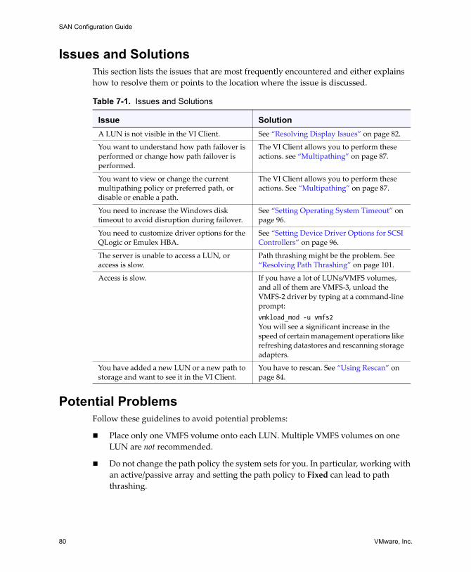
SAN Configuration Guide
80 VMware, Inc.
Issues and SolutionsThis section lists the issues that are most frequently encountered and either explains how to resolve them or points to the location where the issue is discussed.
Potential ProblemsFollow these guidelines to avoid potential problems:
! Place only one VMFS volume onto each LUN. Multiple VMFS volumes on one LUN are not recommended.
! Do not change the path policy the system sets for you. In particular, working with an active/passive array and setting the path policy to Fixed can lead to path thrashing.
Table 7-1. Issues and Solutions
Issue SolutionA LUN is not visible in the VI Client. See �Resolving Display Issues� on page 82.
You want to understand how path failover is performed or change how path failover is performed.
The VI Client allows you to perform these actions. see �Multipathing� on page 87.
You want to view or change the current multipathing policy or preferred path, or disable or enable a path.
The VI Client allows you to perform these actions. See �Multipathing� on page 87.
You need to increase the Windows disk timeout to avoid disruption during failover.
See �Setting Operating System Timeout� on page 96.
You need to customize driver options for the QLogic or Emulex HBA.
See �Setting Device Driver Options for SCSI Controllers� on page 96.
The server is unable to access a LUN, or access is slow.
Path thrashing might be the problem. See �Resolving Path Thrashing� on page 101.
Access is slow. If you have a lot of LUNs/VMFS volumes, and all of them are VMFS‐3, unload the VMFS‐2 driver by typing at a command‐line prompt:vmkload_mod -u vmfs2You will see a significant increase in the speed of certain management operations like refreshing datastores and rescanning storage adapters.
You have added a new LUN or a new path to storage and want to see it in the VI Client.
You have to rescan. See �Using Rescan� on page 84.
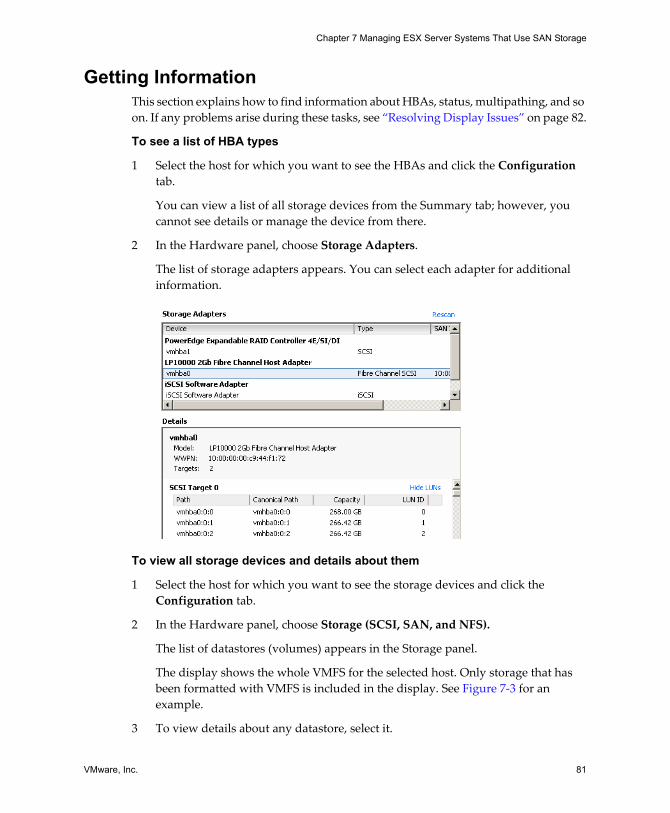
VMware, Inc. 81
Chapter 7 Managing ESX Server Systems That Use SAN Storage
Getting InformationThis section explains how to find information about HBAs, status, multipathing, and so on. If any problems arise during these tasks, see �Resolving Display Issues� on page 82.
To see a list of HBA types
1 Select the host for which you want to see the HBAs and click the Configuration tab.
You can view a list of all storage devices from the Summary tab; however, you cannot see details or manage the device from there.
2 In the Hardware panel, choose Storage Adapters.
The list of storage adapters appears. You can select each adapter for additional information.
To view all storage devices and details about them
1 Select the host for which you want to see the storage devices and click the Configuration tab.
2 In the Hardware panel, choose Storage (SCSI, SAN, and NFS).
The list of datastores (volumes) appears in the Storage panel.
The display shows the whole VMFS for the selected host. Only storage that has been formatted with VMFS is included in the display. See Figure 7‐3 for an example.
3 To view details about any datastore, select it.
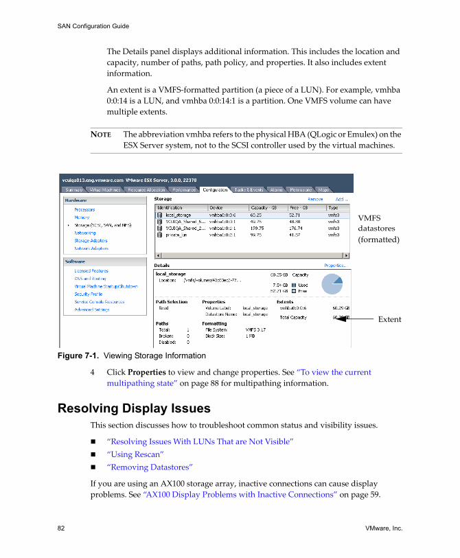
SAN Configuration Guide
82 VMware, Inc.
The Details panel displays additional information. This includes the location and capacity, number of paths, path policy, and properties. It also includes extent information.
An extent is a VMFS‐formatted partition (a piece of a LUN). For example, vmhba 0:0:14 is a LUN, and vmhba 0:0:14:1 is a partition. One VMFS volume can have multiple extents.
NOTE The abbreviation vmhba refers to the physical HBA (QLogic or Emulex) on the ESX Server system, not to the SCSI controller used by the virtual machines.
Figure 7-1. Viewing Storage Information
4 Click Properties to view and change properties. See �To view the current multipathing state� on page 88 for multipathing information.
Resolving Display IssuesThis section discusses how to troubleshoot common status and visibility issues.
! �Resolving Issues With LUNs That are Not Visible�! �Using Rescan�! �Removing Datastores�
If you are using an AX100 storage array, inactive connections can cause display problems. See �AX100 Display Problems with Inactive Connections� on page 59.
(formatted)
VMFS
Extent
datastores
VMware, Inc. 83
Chapter 7 Managing ESX Server Systems That Use SAN Storage
Understanding LUN Naming in the DisplayIn the VI Client, a LUN is displayed as a sequence of three or four numbers, separated by colons:
<SCSI HBA>:<SCSI target>:<SCSI LUN>:<disk partition>
If the last number is 0 or not displayed, the name refers to the entire LUN.
The triple of numbers in an ESX device name may change but still refer to the same physical device. For example, vmhba1:2:3 represents SCSI LUN3, attached to SCSI target 2, on SCSI HBA 1. When the ESX Server system is rebooted, the device name for LUN 3 could change to vmhba1:1:3. The numbers have the following meaning:
! The first number, the SCSI HBA, changes if there is an FC or iSCSI network outage at the time the system is booted or rescanned and ESX is required to access the physical device over a different SCSI HBA.
! The second number, the SCSI target, changes if there is a change in the mappings in the FC or iSCSI targets visible to the ESX Server host.
! The third number, the SCSI LUN, never changes.
Resolving Issues With LUNs That are Not VisibleYou can view LUNs using the VI Client.
If the display (or output) differs from what you expect, check the following:
! Cable connectivity � If you don�t see a port, the problem could be cable connectivity or zoning. Check the cables first.
! Zoning � Zoning limits access to specific storage devices, increases security, and decreases traffic over the network. Some storage vendors allow only single‐initiator zones. In that case, an HBA can be in multiple zones to only one target. Other vendors allow multiple‐initiator zones. See your storage vendor�s documentation for zoning requirements. Use the SAN switch software to configure and manage zoning.
! LUN masking � If an ESX Server host sees a particular storage device but not the expected LUNs on that device, it might be that LUN masking has not been set up properly.
For boot from SAN, ensure that each ESX Server host sees only required LUNs. Particularly, do not allow any ESX Server host to see any boot LUN other than its own. Use disk array software to make sure the ESX Server host can see only the LUNs that it is supposed to see.
SAN Configuration Guide
84 VMware, Inc.
Ensure that the Disk.MaxLUN and Disk.MaskLUNs settings allow you to view the LUN you expect to see. See �Changing the Number of LUNs Scanned Using Disk.MaxLUN� on page 86 and �Masking LUNs Using Disk.MaskLUNs� on page 87.
! Storage processor � If a disk array has more than one storage processor, make sure that the SAN switch has a connection to the SP that owns the LUNs you want to access. On some disk arrays, only one SP is active and the other SP is passive until there is a failure. If you are connected to the wrong SP (the one with the passive path) you might not see the expected LUNs, or you might see the LUNs but get errors when trying to access them.
Using RescanPerform a rescan each time you:
! Zone a new disk array on the SAN to an ESX Server host.! Create new LUNs on a SAN disk array. ! Change the LUN masking on an ESX Server host disk array.! Reseat a cable. ! Make a change to a host in a cluster.
CAUTION Do not rescan when a path is down. If one path fails, the other takes over and your system continues to be fully functional. If, however, you rescan at a time when a path is not available, the ESX Server host removes the path from its list of paths to the device. The path cannot be used by the ESX Server host until the next time a rescan is performed while the path is active.
To perform a rescan
1 In the VI Client, select a host and click the Configuration tab.
2 In the Hardware panel, choose Storage Adapters, and then click Rescan above the Storage Adapters panel.
NOTE You can also select an individual adapter and click Rescan to rescan just that adapter.
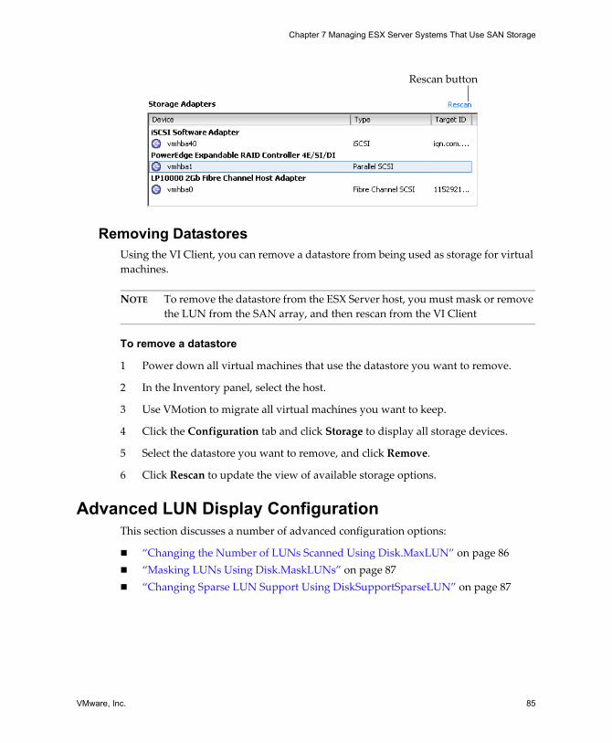
VMware, Inc. 85
Chapter 7 Managing ESX Server Systems That Use SAN Storage
Removing Datastores Using the VI Client, you can remove a datastore from being used as storage for virtual machines.
NOTE To remove the datastore from the ESX Server host, you must mask or remove the LUN from the SAN array, and then rescan from the VI Client
To remove a datastore
1 Power down all virtual machines that use the datastore you want to remove.
2 In the Inventory panel, select the host.
3 Use VMotion to migrate all virtual machines you want to keep.
4 Click the Configuration tab and click Storage to display all storage devices.
5 Select the datastore you want to remove, and click Remove.
6 Click Rescan to update the view of available storage options.
Advanced LUN Display ConfigurationThis section discusses a number of advanced configuration options:
! �Changing the Number of LUNs Scanned Using Disk.MaxLUN� on page 86! �Masking LUNs Using Disk.MaskLUNs� on page 87! �Changing Sparse LUN Support Using DiskSupportSparseLUN� on page 87
Rescan button
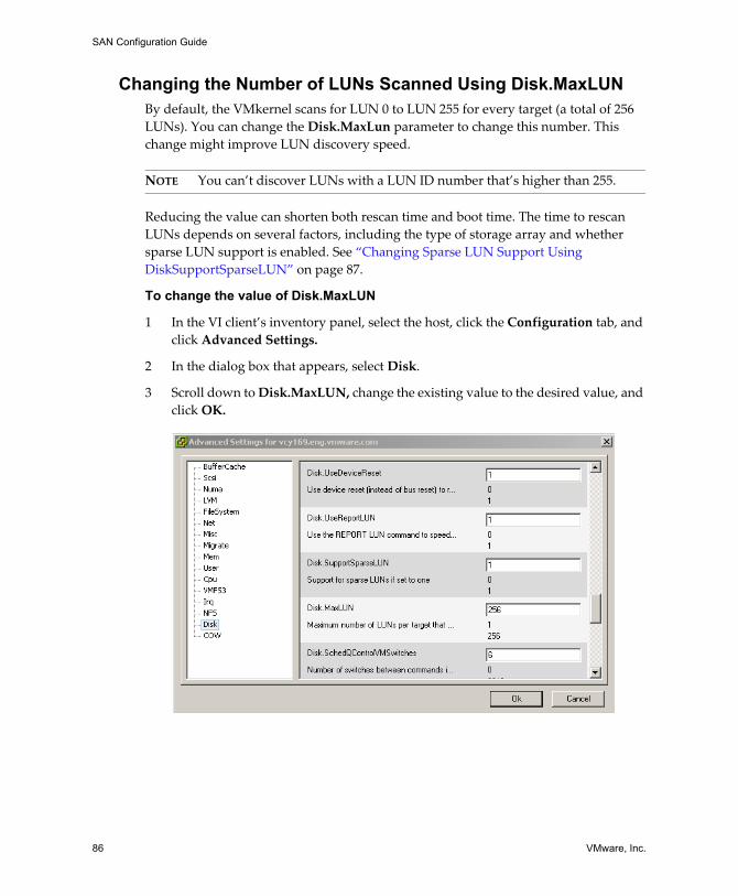
SAN Configuration Guide
86 VMware, Inc.
Changing the Number of LUNs Scanned Using Disk.MaxLUNBy default, the VMkernel scans for LUN 0 to LUN 255 for every target (a total of 256 LUNs). You can change the Disk.MaxLun parameter to change this number. This change might improve LUN discovery speed.
NOTE You can�t discover LUNs with a LUN ID number that�s higher than 255.
Reducing the value can shorten both rescan time and boot time. The time to rescan LUNs depends on several factors, including the type of storage array and whether sparse LUN support is enabled. See �Changing Sparse LUN Support Using DiskSupportSparseLUN� on page 87.
To change the value of Disk.MaxLUN
1 In the VI client�s inventory panel, select the host, click the Configuration tab, and click Advanced Settings.
2 In the dialog box that appears, select Disk.
3 Scroll down to Disk.MaxLUN, change the existing value to the desired value, and click OK.
VMware, Inc. 87
Chapter 7 Managing ESX Server Systems That Use SAN Storage
Masking LUNs Using Disk.MaskLUNsThe Disk.MaskLUNs parameter allows you to mask specific LUNs on specific HBAs. Masked LUNs are not touched or accessible by the VMkernel, even during initial scanning.
Use this option when you want to prevent the ESX Server system from accessing some FC LUNs, but do not want to use the FC switch or FC device LUN masking mechanims.
To change the value of Disk.MaskLUNs
1 In the VI client�s inventory panel, select the host, click the Configuration tab, and click Advanced Settings.
2 In the dialog box that appears, select Disk.
3 Scroll down to Disk.MaskLUNs, change the existing value to the desired value, and click OK.
CAUTION If a target, LUN, or vmhba number changes because of a server or SAN reconfiguration, the incorrect LUN may be masked or exposed.
Changing Sparse LUN Support Using DiskSupportSparseLUNBy default, the VMkernel is configured to support sparse LUNs�that is, a case where some LUNs in the range 0 to N‐1 are not present, but LUN N is present.
If all LUNs are sequential, you can change the Disk.SupportSparseLUN parameter. This change decreases the time needed to scan for LUNs.
To change the value of Disk.SupportSparseLUN
1 In the VI client�s inventory panel, select the host, click the Configuration tab, and click Advanced Settings.
2 In the dialog box that appears, select Disk.
3 Scroll down to Disk.SupportSparseLUN, change the value to 0, and click OK.
MultipathingThis section discusses the following multipathing topics:
! �Viewing the Current Multipathing State� on page 88! �Setting a LUN�s Multipathing Policy� on page 90! �Disabling and Enabling Paths� on page 91
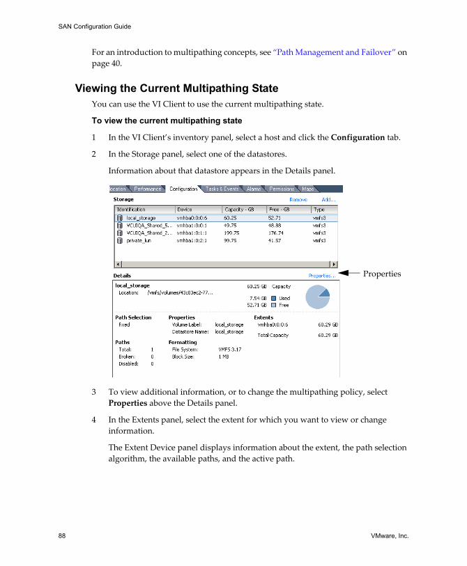
SAN Configuration Guide
88 VMware, Inc.
For an introduction to multipathing concepts, see �Path Management and Failover� on page 40.
Viewing the Current Multipathing StateYou can use the VI Client to use the current multipathing state.
To view the current multipathing state
1 In the VI Client�s inventory panel, select a host and click the Configuration tab.
2 In the Storage panel, select one of the datastores.
Information about that datastore appears in the Details panel.
3 To view additional information, or to change the multipathing policy, select Properties above the Details panel.
4 In the Extents panel, select the extent for which you want to view or change information.
The Extent Device panel displays information about the extent, the path selection algorithm, the available paths, and the active path.
Properties
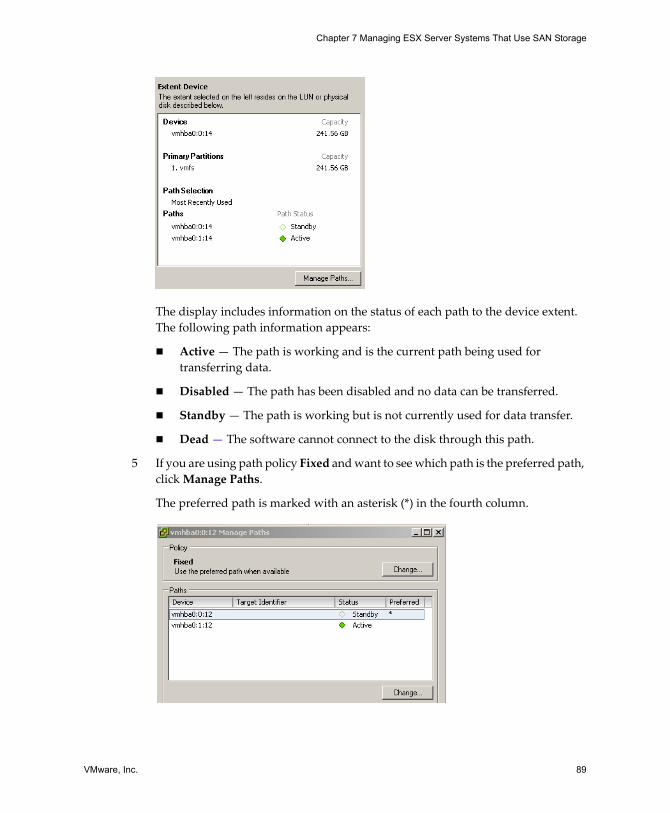
VMware, Inc. 89
Chapter 7 Managing ESX Server Systems That Use SAN Storage
The display includes information on the status of each path to the device extent. The following path information appears:
! Active � The path is working and is the current path being used for transferring data.
! Disabled � The path has been disabled and no data can be transferred.
! Standby � The path is working but is not currently used for data transfer.
! Dead � The software cannot connect to the disk through this path.
5 If you are using path policy Fixed and want to see which path is the preferred path, click Manage Paths.
The preferred path is marked with an asterisk (*) in the fourth column.
SAN Configuration Guide
90 VMware, Inc.
Table 7‐2 summarizes how the behavior of an ESX Server system changes, depending on the type of array and the failover policy.
Active PathsESX Server does not typically perform I/O load balancing across paths for a given LUN. At any one time, only a single path is used to issue I/O to a given LUN. This path is known as the active path.
! If the path policy of a LUN is set to Fixed, ESX Server selects the path marked as Preferred as the active path.
If the preferred path is disabled or unavailable, the ESX Server system uses an alternate working path as the active path.
! If the path policy of a LUN is set to Most Recently Used, the ESX Server host selects an active path to the LUN that prevents path thrashing. The preferred path designation is not considered.
In some SAN terminology, the term active means any path that is available for issuing I/O to a LUN. From the ESX Server host�s point of view, the term active means the one and only path that the ESX Server host is using to issue I/O to a LUN.
Setting a LUN�s Multipathing PolicyThe following multipathing policies are currently supported:
! Fixed � The ESX Server host always uses the preferred path to the disk when that path is available. If it cannot access the disk through the preferred path, then it tries the alternate paths. Fixed is the default policy for active/active storage devices.
! Most Recently Used � The ESX Server host uses the most recent path to the disk until this path becomes unavailable. That is, the ESX Server host does not automatically revert back to the preferred path. Most Recently Used is the default policy for active/passive storage devices and is required for those devices.
Table 7-2. Path Policy Effects
Policy/Controller Active/Active Active/PassiveMost Recently Used Administrator action is required
to fail back after path failure. Administrator action is required to fail back after path failure.
Fixed VMkernel resumes using the preferred path when connectivity is restored.
VMkernel attempts to resume using the preferred path. This can cause path thrashing or failure because another SP now owns the LUN. See �Resolving Path Thrashing� on page 101.
VMware, Inc. 91
Chapter 7 Managing ESX Server Systems That Use SAN Storage
The ESX Server host automatically sets the multipathing policy according to the make and model of the array it detects. If the detected array is not supported, it is treated as active/active. For a list of supported arrays, see the SAN Compatibility Guide.
NOTE Manually changing Most Recently Used to Fixed is not recommended. The system sets this policy for those arrays that require it.
To set the multipathing policy using a VI Client
1 In the VI Client�s inventory panel, select the host and click the Configuration tab.
2 In the Hardware panel, select Storage.
3 Select the datastore for which you want to change the multipathing policy, and then click Properties in the Details panel.
4 In the Extent panel, select the device for which you want to make the change, and click Manage Paths in the Extent Device panel on the right.
5 Select the desired multipathing policy in the dialog box that appears and click Done.
NOTE For active/passive storage devices, Most Recently Used is highly recommended.
Disabling and Enabling PathsYou might want to temporarily disable paths for maintenance or other reasons. You can do so using the VI Client.
To disable a path
1 In the VI Client�s inventory panel, select the host and click the Configuration tab.
2 In the Hardware panel, select Storage.
3 Select the device for which you want to disable a path, and then click Properties in the Details panel.
4 In the Extent panel, select the device for which you want to make the change, and then click Manage Paths in the Extent Device panel on the right.
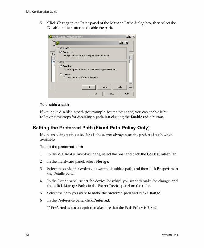
SAN Configuration Guide
92 VMware, Inc.
5 Click Change in the Paths panel of the Manage Paths dialog box, then select the Disable radio button to disable the path.
To enable a path
If you have disabled a path (for example, for maintenance) you can enable it by following the steps for disabling a path, but clicking the Enable radio button.
Setting the Preferred Path (Fixed Path Policy Only)If you are using path policy Fixed, the server always uses the preferred path when available.
To set the preferred path
1 In the VI Client�s Inventory pane, select the host and click the Configuration tab.
2 In the Hardware panel, select Storage.
3 Select the device for which you want to disable a path, and then click Properties in the Details panel.
4 In the Extent panel, select the device for which you want to make the change, and then click Manage Paths in the Extent Device panel on the right.
5 Select the path you want to make the preferred path and click Change.
6 In the Preference pane, click Preferred.
If Preferred is not an option, make sure that the Path Policy is Fixed.
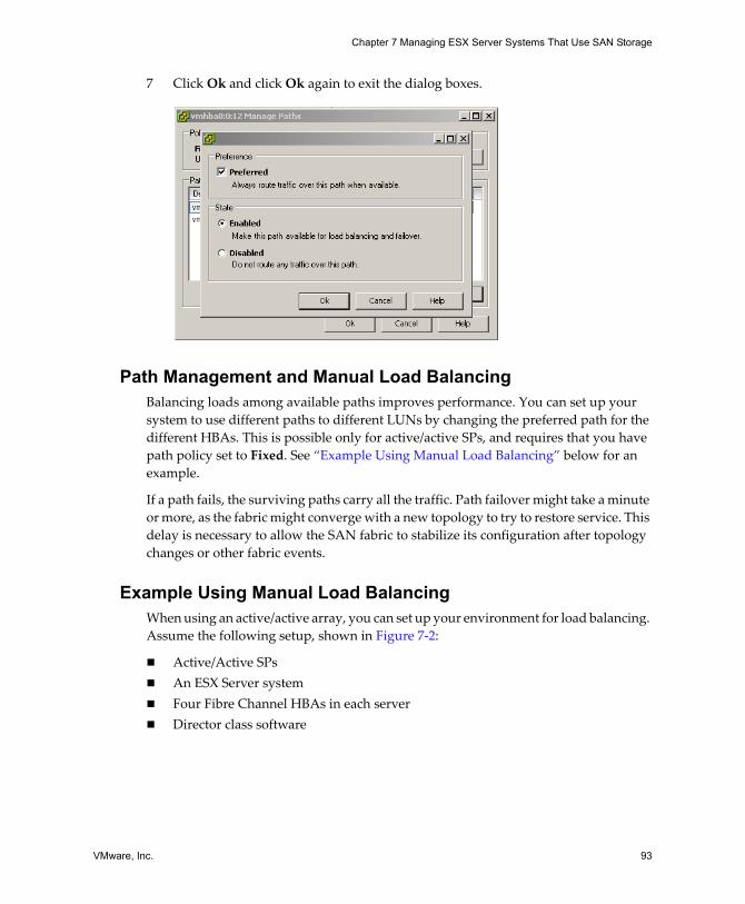
VMware, Inc. 93
Chapter 7 Managing ESX Server Systems That Use SAN Storage
7 Click Ok and click Ok again to exit the dialog boxes.
Path Management and Manual Load BalancingBalancing loads among available paths improves performance. You can set up your system to use different paths to different LUNs by changing the preferred path for the different HBAs. This is possible only for active/active SPs, and requires that you have path policy set to Fixed. See �Example Using Manual Load Balancing� below for an example.
If a path fails, the surviving paths carry all the traffic. Path failover might take a minute or more, as the fabric might converge with a new topology to try to restore service. This delay is necessary to allow the SAN fabric to stabilize its configuration after topology changes or other fabric events.
Example Using Manual Load BalancingWhen using an active/active array, you can set up your environment for load balancing. Assume the following setup, shown in Figure 7‐2:
! Active/Active SPs! An ESX Server system! Four Fibre Channel HBAs in each server! Director class software
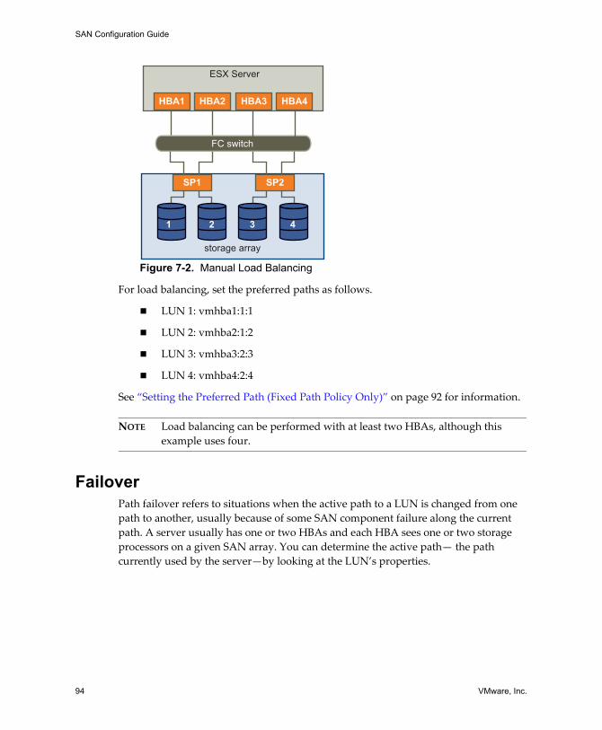
SAN Configuration Guide
94 VMware, Inc.
Figure 7-2. Manual Load Balancing
For load balancing, set the preferred paths as follows.
! LUN 1: vmhba1:1:1
! LUN 2: vmhba2:1:2
! LUN 3: vmhba3:2:3
! LUN 4: vmhba4:2:4
See �Setting the Preferred Path (Fixed Path Policy Only)� on page 92 for information.
NOTE Load balancing can be performed with at least two HBAs, although this example uses four.
FailoverPath failover refers to situations when the active path to a LUN is changed from one path to another, usually because of some SAN component failure along the current path. A server usually has one or two HBAs and each HBA sees one or two storage processors on a given SAN array. You can determine the active path� the path currently used by the server�by looking at the LUN�s properties.
storage array
ESX Server
SP1 SP2
3 421
FC switch
HBA2HBA1 HBA4HBA3
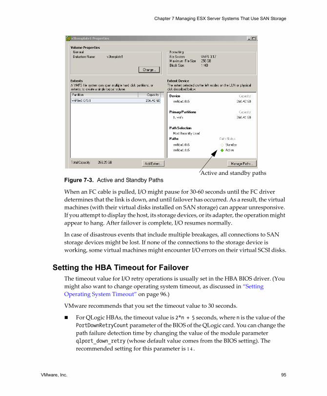
VMware, Inc. 95
Chapter 7 Managing ESX Server Systems That Use SAN Storage
Figure 7-3. Active and Standby Paths
When an FC cable is pulled, I/O might pause for 30‐60 seconds until the FC driver determines that the link is down, and until failover has occurred. As a result, the virtual machines (with their virtual disks installed on SAN storage) can appear unresponsive. If you attempt to display the host, its storage devices, or its adapter, the operation might appear to hang. After failover is complete, I/O resumes normally.
In case of disastrous events that include multiple breakages, all connections to SAN storage devices might be lost. If none of the connections to the storage device is working, some virtual machines might encounter I/O errors on their virtual SCSI disks.
Setting the HBA Timeout for FailoverThe timeout value for I/O retry operations is usually set in the HBA BIOS driver. (You might also want to change operating system timeout, as discussed in �Setting Operating System Timeout� on page 96.)
VMware recommends that you set the timeout value to 30 seconds.
! For QLogic HBAs, the timeout value is 2*n + 5 seconds, where n is the value of the PortDownRetryCount parameter of the BIOS of the QLogic card. You can change the path failure detection time by changing the value of the module parameter qlport_down_retry (whose default value comes from the BIOS setting). The recommended setting for this parameter is 1 4 .
Active and standby paths
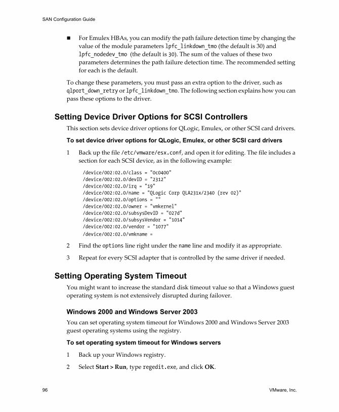
SAN Configuration Guide
96 VMware, Inc.
! For Emulex HBAs, you can modify the path failure detection time by changing the value of the module parameters lpfc_linkdown_tmo (the default is 30) and lpfc_nodedev_tmo (the default is 30). The sum of the values of these two parameters determines the path failure detection time. The recommended setting for each is the default.
To change these parameters, you must pass an extra option to the driver, such as qlport_down_retry or lpfc_linkdown_tmo. The following section explains how you can pass these options to the driver.
Setting Device Driver Options for SCSI ControllersThis section sets device driver options for QLogic, Emulex, or other SCSI card drivers.
To set device driver options for QLogic, Emulex, or other SCSI card drivers
1 Back up the file /etc/vmware/esx.conf, and open it for editing. The file includes a section for each SCSI device, as in the following example:
/device/002:02.0/class = "0c0400"/device/002:02.0/devID = "2312"/device/002:02.0/irq = "19"/device/002:02.0/name = "QLogic Corp QLA231x/2340 (rev 02)"/device/002:02.0/options = ""/device/002:02.0/owner = "vmkernel"/device/002:02.0/subsysDevID = "027d"/device/002:02.0/subsysVendor = "1014"/device/002:02.0/vendor = "1077"
/device/002:02.0/vmkname = "vmhba0"
2 Find the options line right under the name line and modify it as appropriate.
3 Repeat for every SCSI adapter that is controlled by the same driver if needed.
Setting Operating System TimeoutYou might want to increase the standard disk timeout value so that a Windows guest operating system is not extensively disrupted during failover.
Windows 2000 and Windows Server 2003 You can set operating system timeout for Windows 2000 and Windows Server 2003 guest operating systems using the registry.
To set operating system timeout for Windows servers
1 Back up your Windows registry.
2 Select Start > Run, type regedit.exe, and click OK.
VMware, Inc. 97
Chapter 7 Managing ESX Server Systems That Use SAN Storage
3 In the left panel hierarchy view, double‐click first HKEY_LOCAL_MACHINE, then System, then CurrentControlSet, then Services, and then Disk.
4 Select the TimeOutValue and set the data value to x03c (hexadecimal) or 60 (decimal).
After you�ve made this change, Windows waits at least 60 seconds for delayed disk operations to complete before it generates errors.
5 Click OK to exit the Registry Editor.
VMkernel ConfigurationWhen you install your ESX Server system, you decide where to place different storage elements such as the / and /boot partitions of the service console. The different components are discussed in more detail in the Installation and Upgrade Guide.
Sharing Diagnostic PartitionsIf your ESX Server host has a local disk, that disk is most appropriately used for the diagnostic partition. One reason is that if there is an issue with remote storage that causes a core dump, the core dump is lost and resolving the issue becomes more difficult.
However, for diskless servers that boot from SAN, multiple ESX Server systems can share one diagnostic partition on a SAN LUN. If more than one ESX Server system is using a LUN as a diagnostic partition, that LUN must be zoned so that all the servers can access it.
Each server needs 100MB of space, so the size of the LUN determines how many servers can share it. Each ESX Server system is mapped to a diagnostic slot. VMware recommends at least 16 slots (1600MB) of disk space if servers share a diagnostic partition.
If there is only one diagnostic slot on the device, then all ESX Server systems sharing that device map to the same slot. This can easily create problems. If two ESX Server systems perform a core dump at the same time, the core dumps are overwritten on the last slot on the diagnostic partition.
If you allocate enough memory for 16 slots, it is unlikely that core dumps are mapped to the same location on the diagnostic partition, even if two ESX Server systems perform a core dump at the same time.
SAN Configuration Guide
98 VMware, Inc.
Avoiding and Resolving ProblemsThis section gives some tips for avoiding and resolving problems:
! Document everything. Include information about zoning, access control, storage, switch, server and FC HBA configuration, software and firmware versions, and storage cable plan.
! Plan for failure:
! Take your topology maps and make several copies. For each element, consider what happens to your SAN if the element fails.
! Cross off different links, switches, HBAs and other elements to ensure you didn�t miss a critical failure point in your design.
! Disconnect the Fibre Channel HBAs during local installation when you install an ESX Server host on a production system.
CAUTION The installer lets you erase any accessible disks, including SAN LUNs in use by other servers.
! Ensure that the Fibre Channel HBAs are installed in the correct slots in the ESX Server host, based on slot and bus speed. Balance PCI bus load among the available busses in the server.
! Become familiar with the various monitor points in your storage network, at all visibility points, including ESX Server performance charts, FC switch statistics, and storage performance statistics.
Optimizing SAN Storage PerformanceThe two major factors for optimizing a typical SAN environment are storage array performance and server performance. If the environment is properly configured, the SAN fabric components (particularly the SAN switches) are only minor contributors because of their low latencies relative to servers and storage arrays. Ensure that the paths through the switch fabric are not saturated, that is, the switch fabric is running at the highest throughput (for example, 2GB/s).
Storage Array PerformanceIf there are issues with storage array performance, be sure to consult your storage array vendor�s documentation for any relevant information.
When assigning LUNs, remember that each LUN is accessed by a number of ESX Server hosts, and that a number of virtual machines can run on each host. One LUN used by
VMware, Inc. 99
Chapter 7 Managing ESX Server Systems That Use SAN Storage
an ESX Server host can service I/O from many different applications running on different operating systems. Because of this diverse workload, the RAID group containing the ESX Server LUNs should not include LUNs used by other hosts that are not running ESX Server for I/O intensive applications.
Make sure read/write caching is enabled.
Load balancing is the process of spreading server I/O requests across all available SPs and their associated host server paths. The goal is to optimize performance in terms of throughput (I/O per second, megabytes per second, or response times).
SAN storage arrays require continual redesign and tuning to ensure that I/O is load balanced across all storage array paths. To meet this requirement, distribute the paths to the LUNs among all the SPs to provide optimal load balancing. Close monitoring indicates when it is necessary to manually rebalance the LUN distribution. See �Path Management and Manual Load Balancing� on page 93 for an example.
Tuning statically balanced storage arrays is a matter of monitoring the specific performance statistics (such as I/O operations per second, blocks per second, and response time) and distributing the LUN workload to spread the workload across all the SPs.
NOTE Dynamic load balancing is not currently supported with ESX Server.
Server PerformanceEnsuring optimal server performance requires looking at a number of factors. Each server application must have access to its designated storage with:
! High I/O rate (number of I/O operations per second)! High throughput (megabytes per second)! Minimal latency (response times)
Because each application has different requirements, you can meet these goals by choosing an appropriate RAID group on the storage array. To achieve performance goals:
! Place each LUN on a RAID group that provides the necessary performance levels. Pay particular attention to the activities and resource utilization of other LUNS in the assigned RAID group. A high‐performance RAID group that has too many applications doing I/O to it might not meet performance goals required by an application running on the ESX Server host.
! Make sure that each server has a sufficient number of HBAs to allow maximum throughput for all the applications hosted on the server for the peak period. I/O
SAN Configuration Guide
100 VMware, Inc.
spread across multiple HBAs provide higher throughput and less latency for each application.
! To provide redundancy in the event of HBA failure, make sure the server is connected to a dual redundant fabric.
! When allocating LUNs or RAID groups for ESX Server systems, keep in mind that multiple operating systems will use and share that resource. As a result, the performance required from each LUN in the storage subsystem can be much higher if you are working with ESX Server systems than if you are using physical machines. For example, if you expect to run four I/O intensive applications, allocate four times the performance capacity for the ESX Server LUNs.
! When using multiple ESX Server systems in conjunction with a VirtualCenter Server, the performance needed from the storage subsystem increases correspondingly.
! The number of outstanding I/Os needed by applications running on an ESX Server system should match the number of I/Os the HBA and storage array can handle.
Resolving Performance IssuesThis section discusses performance monitoring and possible ways of resolving performance issues:
! �Monitoring Performance� on page 100! �Resolving Path Thrashing� on page 101! �Equalizing Disk Access Between Virtual Machines� on page 103
NOTE For best performance, place each virtual machine on the appropriate tier of storage. See �Choosing Virtual Machine Locations� on page 41 for information.
Monitoring PerformanceThe VI Client offers extensive facilities for collecting performance information. The information is then graphically displayed in the VI Client. For information, see the Virtual Infrastructure User�s Guide. The VI Client updates its display periodically.
You can also use the esxtop tool, available from the service console. For information about esxtop, see the Resource Management Guide, or look at the man page from the service console. You can use esxtop to monitor performance in real time.

VMware, Inc. 101
Chapter 7 Managing ESX Server Systems That Use SAN Storage
Resolving Path ThrashingIf your server is unable to access a LUN, or access is very slow, you might have a problem with path thrashing (sometimes called LUN thrashing). In path thrashing, two hosts access the LUN via different SPs, and, as a result, the LUN is never actually available.
This problem usually occurs in conjunction with certain SAN configurations and under these circumstances:
! You are working with an active/passive array.
! Path policy is set to Fixed.
! Two hosts access the LUN using opposite path order. For example, Host A is set up to access the lower‐numbered LUN via SP A. Host B is set up to access the lower‐numbered LUN via SP B.
Path thrashing can also occur if Host A lost a certain path and can use only paths to SP A while host B lost other paths and can use only paths to SP B.
This problem could also occur on a direct connect array (such as AX100) with HBA failover on one or more nodes.
Path thrashing is a problem that you typically won�t experience with other operating systems:
! No other common operating system uses shared LUNs for more than two servers (that setup is typically reserved for clustering).
! For clustering, only one server is issuing I/Os at a time. Path thrashing does not become a problem.
In contrast, multiple ESX Server systems may be issuing I/O to the same LUN concurrently.
To resolve path thrashing
! Ensure all hosts sharing the same set of LUNs on those active/passive arrays access the same storage processor simultaneously.
! Correct any cabling inconsistencies between different ESX Server hosts and SAN targets so that all HBAs see the same targets in the same order.
! Make sure the path policy is set to Most Recently Used (the default).
SAN Configuration Guide
102 VMware, Inc.
Understanding Path Thrashing In all arrays the SPs are like independent computers that have access to some shared storage. Algorithms determine how concurrent access is handled.
! For active/passive arrays, all the sectors on the storage that make up a given LUN can be accessed by only one LUN at a time. The ownership is passed around between the storage processors. The reason is that storage arrays use caches and SP A must not write something to disk that invalidates SP Bʹs cache. Because the SP has to flush the cache when it�s done with its operation, it takes a little time to move the ownership. During that time, no I/Oʹs to the LUN can be processed by either SP.
! For active/active arrays, the algorithms allow more fine‐grained access to the storage and synchronize caches. Access can happen concurrently through any SP without extra time required.
Arrays with AVT are active/passive arrays that attempt to look like active/active arrays by passing the ownership of the LUN to the various SPs as I/O arrives. This approach is fine in a clustering setup, but if many ESX Server systems access the same LUN concurrently through different SPs, the result is LUN thrashing.
Consider how path selection works:
! On an active/active array the system starts sending I/O down the new path.
! For active/passive arrays, the ESX Server system checks all standby paths. The SP at the end of the path that is currently under consideration sends information to the system on whether it currently owns the LUN.
! If the ESX Server system finds an SP that owns the LUN, that path is selected and I/O is sent down that path.
! If the ESX Server host cannot find such path, the ESX Server host picks one of the paths and sends the SP (at the other end of the path) a command to move the LUN ownership to this SP.
Path thrashing can occur as a result of this path choice: If server A can reach a LUN only through one SP, and server B can reach the same LUN only through a different SP, they both continuously cause the ownership of the LUN to move between the two SP�s, effectively ping‐ponging the ownership of the LUN. Because the system moves the ownership quickly, the storage array cannot process any I/O (or can process only very little). As a result, any servers that depend on the LUN start timing out I/O.
VMware, Inc. 103
Chapter 7 Managing ESX Server Systems That Use SAN Storage
Equalizing Disk Access Between Virtual MachinesYou can adjust the maximum number of outstanding disk requests with the Disk.SchedNumReqOutstanding parameter in the VI Client. When two or more virtual machines are accessing the same LUN, this parameter controls the number of outstanding requests each virtual machine can issue to the LUN. Adjusting the limit can help equalize disk access between virtual machines.
This limit is inapplicable when only one virtual machine is active on a LUN. In that case, the bandwidth is limited by the queue depth of the storage adapter.
To set the number of outstanding disk requests
1 In the VI Client, select the host in the inventory panel.
2 Click the Configuration tab and click Advanced Settings.
3 Click Disk in the left panel and scroll down to Disk.SchedNumReqOutstanding.
4 Change the parameter value to the desired number and click OK.
5 Reboot the server.
This change can impact disk bandwidth scheduling, but experiments have shown improvements for disk‐intensive workloads.
If you adjust this value in the VMkernel, you might also want to adjust the queue depth in your storage adapter. See �Setting Maximum Queue Depth for the HBA� below.
Removing VMFS-2 DriversIf you have a lot of LUNs/VMFS volumes, and all of them are VMFS‐3, you can potentially improve performance by unloading the VMFS‐2 driver. At a command‐line prompt, type:
vmkload_mod -u vmfs2
A significant increase in the speed of certain management operations like refreshing datastores and rescanning storage adapters should result.
Reducing SCSI ReservationsOperations that require getting a file lock or a metadata lock in VMFS result in short‐lived SCSI reservations. SCSI reservations lock an entire LUN. Excessive SCSI reservations by a server can cause performance degradation on other servers accessing the same VMFS.
SAN Configuration Guide
104 VMware, Inc.
Examples of operations that require getting file locks or metadata locks include:
! Virtual machine power on.
! VMotion.
! Virtual machines running with virtual disk snapshots.
! File operations from the service console requiring opening files or doing metadata updates. (See �Metadata Updates� on page 32.)
Therefore, there can be performance degradation if such operations are happening frequently on multiple servers accessing the same VMFS. For instance, it is not recommended to run many virtual machines from multiple servers that are using virtual disk snapshots on the same VMFS. Similarly, you should limit the number of VMFS file operations that are executed from the service console when many virtual machines are running on the VMFS.
Setting Maximum Queue Depth for the HBAYou can adjust the maximum queue depth for a QLogic qla2x00 series adapter with the following procedure. You should change the maximum queue depth only if you notice unsatisfactory performance.
To set maximum queue depth
1 Back up the file /etc/vmware/esx.conf and open it for editing.
The file looks similar to the following example:
/device/002:02.0/class = "0c0400"/device/002:02.0/devID = "2312"/device/002:02.0/irq = "19"/device/002:02.0/name = "QLogic Corp QLA231x/2340 (rev 02)"/device/002:02.0/options = ""/device/002:02.0/owner = "vmkernel"/device/002:02.0/subsysDevID = "027d"/device/002:02.0/subsysVendor = "1014"/device/002:02.0/vendor = "1077"
/device/002:02.0/vmkname = "vmhba0"
2 Find the options line right under the name line and modify it to specify the maximum queue depth, as follows (where nn is the queue depth maximum):
/device/001:02.0/options = "ql2xmaxqdepth=nn"
NOTE The second character in ql2xmaxqdepth is a lowercase �L�.
3 Save your changes and reboot the server.
VMware, Inc. 105
Chapter 7 Managing ESX Server Systems That Use SAN Storage
SAN Storage Backup ConsiderationsThis section discusses some backup considerations in the following sections:
! �Backups in a SAN Environment� on page 105! �Snapshot Software� on page 106! �Using a Third‐Party Backup Package� on page 106! �Choosing Your Backup Solution� on page 107
Backups in a SAN EnvironmentWithin the SAN environment, backups have two goals. The first goal is to archive online data to offline media. This process is repeated periodically for all online data on a time schedule. The second goal is to provide access to offline data for recovery from a problem. For example, database recovery often requires retrieval of archived log files that are not currently online.
Scheduling a backup depends on a number of factors:
! Identification of critical applications that require more frequent backup cycles within a given period of time.
! Recovery point and recovery time goals. Consider how precise your recovery point needs to be, and how long you are willing to wait for it.
! The rate of change (RoC) associated with the data. For example, if you are using synchronous/asynchronous replication, the RoC affects the amount of bandwidth required between the primary and secondary storage devices.
! Overall impact on SAN environment, storage performance (while backing up), and other applications.
! Identification of peak traffic periods on the SAN (backups scheduled during those peak periods can slow the applications and the backup process).
! Time to schedule all backups within the datacenter.
! Time it takes to back up an individual application.
! Resource availability for archiving data; usually offline media access (tape).
Include a recovery‐time objective for each application when you design your backup strategy. That is, consider the time and resources necessary to reprovision the data. For example, if a scheduled backup stores so much data that recovery requires a considerable amount of time, the scheduled backup should be re‐examined. It might be better to perform the backup more frequently, so that less data is backed up at a time and the recovery time decreases.
SAN Configuration Guide
106 VMware, Inc.
If a particular application requires recovery within a certain time frame, then the backup process needs to provide a time schedule and specific data processing to meet this requirement. Fast recovery can require the use of recovery volumes that reside on online storage to minimize or eliminate the need to access slow offline media for missing data components.
Snapshot SoftwareSnapshot software allows an administrator to make an instantaneous copy of any single virtual disk defined within the disk subsystem. Snapshot software is available at different levels:
! ESX Server hosts allow you to create snapshots of virtual machines. This software is included in the basic ESX Server package.
! Third‐party backup software might allow for more comprehensive backup procedures and might contain more sophisticated configuration options.
Administrators make snapshots for a variety of reasons, including:
! Backup.
! Disaster recovery.
! Availability of multiple configurations, versions, or both.
! Forensics (looking at a snapshot to find the cause of problems while your system is back up and running).
! Data mining (looking at a copy of your data to reduce load on production systems).
Using a Third-Party Backup PackageIf you are using third‐party backup software, you must first make sure that software is supported with ESX Server hosts. See the Backup Compatibility Guide at http://www.vmware.com/pdf/esx_backup_guide.pdf for more information.
Using third‐party software has the advantage of a uniform environment. However, you have to consider that the additional cost of the third‐party snapshotting software can become higher as your SAN grows.
If you decide to use snapshots to back up your data, you must consider the following points:
! Some vendors support snapshots for both VMFS and RDMs. If both are supported, you can make either a snapshot of the whole virtual machine file system for a host, or snapshots for the individual virtual machines (one per disk).
VMware, Inc. 107
Chapter 7 Managing ESX Server Systems That Use SAN Storage
! Some vendors support snapshots only for a setup using RDM. If only RDM is supported, you can make snapshots of individual virtual machines.
See your storage vendor�s documentation for additional information.
NOTE ESX Server systems also include a Consolidated Backup component, which is discussed in detail in the Virtual Machine Backup Guide.
Choosing Your Backup SolutionWhen choosing your backup solution, consider that a backup can be one or all of these:
! Crash consistent ! File system consistent! Application consistent
VMware offers a file‐system‐consistent backup. In most cases, a file‐system‐consistent backup allows you to completely recover from failure. However, if your applications require synchronization across file systems or with a database, the VMware solution might not provide enough consistency. In these cases, you should investigate a third‐party backup solution to see whether it better suits your needs.
Layered Applications SAN administrators are customarily using specialized array‐based software for backup, disaster recovery, data mining, forensics, and configuration test. ESX Server administrators might be used to working with tools included with the ESX Server host for performing the same operations. When you use an ESX Server system in conjunction with a SAN, you need to decide whether array‐based or host‐based tools are more suitable for your particular situation.
Array-Based (Third-Party) SolutionWhen considering an array‐based solution, consider the following points:
! If you use the array‐based solution, RDM (not VMFS) is usually the appropriate choice. If you do not intend to use RDM, you must check the vendor�s documentation to see if operations on virtual disks are supported.
! Array‐based solutions usually result in more comprehensive statistics. With RDM, data always go along the same path, which results in easier performance management.
SAN Configuration Guide
108 VMware, Inc.
! Security tends to be more manageable when you use RDM and an array‐based solution because with RDM, virtual machines more closely resemble physical machines.
File-Based (VMware) SolutionWhen considering a file‐based solution using VMware tools and VMFS, be aware of the of the following points:
! Using VMware tools and VMFS is better for provisioning: one large LUN is allocated and multiple .vmdk files can be placed on that LUN. With RDM, a new LUN is required for each virtual machine.
! Snapshotting and replication is included with your ESX Server host at no extra cost. The file‐based solution is therefore more cost‐effective than the array‐based solution.
! For ESX Server administrators, using ESX Server tools is easier.
! ESX Server administrators who use the file‐based solution are more independent from the SAN administrator.
VMFS Volume Resignaturing VMFS volume resignaturing allows you to make a hardware snapshot of a VMFS volume and access that snapshot from an ESX Server system. It involves resignaturing the volume UUID and creating a new volume label. You can control resignaturing as follows:
! Use the LVM.EnableResignature option to turn auto‐resignaturing on or off (default is off).
! As a rule, a LUN should appear with the same LUN ID to all hosts that access the LUN. Under certain circumstances, you need to change this behavior using the LVM.DisallowSnapshotLUN option.
To mount both the original and snapshot VMFS volumes on the same ESX Server host
1 In the VI Client, select the host in the inventory panel.
2 Click the Configuration tab and click Advanced Settings.
3 Perform the following tasks repeatedly, as needed:
a Make the snapshot.
b Add the snapshot to the storage array.
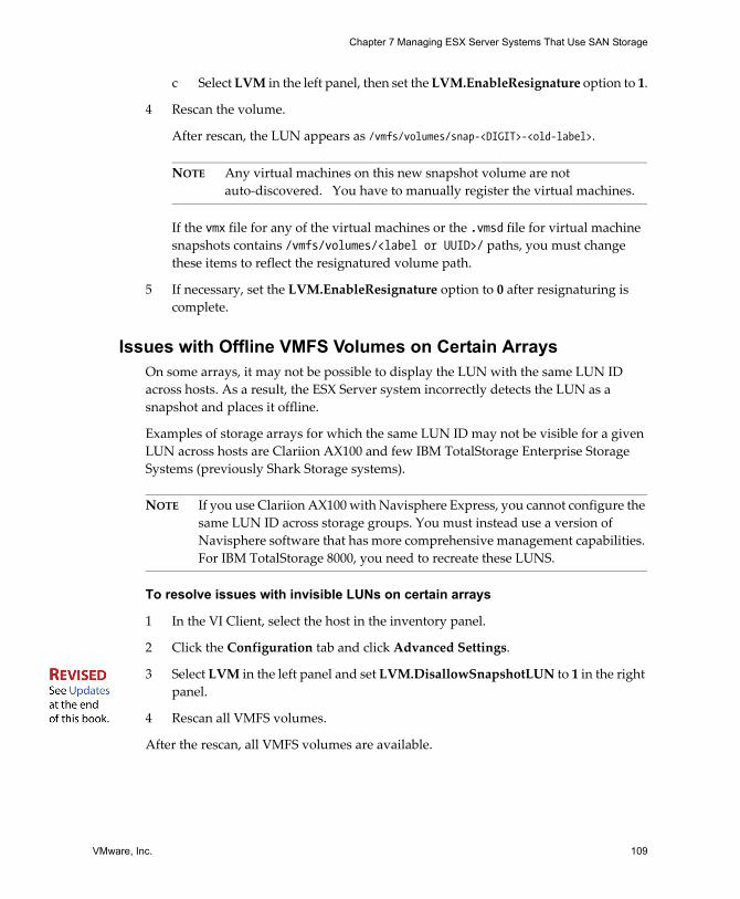
VMware, Inc. 109
Chapter 7 Managing ESX Server Systems That Use SAN Storage
c Select LVM in the left panel, then set the LVM.EnableResignature option to 1.
4 Rescan the volume.
After rescan, the LUN appears as /vmfs/volumes/snap-<DIGIT>-<old-label>.
NOTE Any virtual machines on this new snapshot volume are not auto‐discovered. You have to manually register the virtual machines.
If the vmx file for any of the virtual machines or the .vmsd file for virtual machine snapshots contains /vmfs/volumes/<label or UUID>/ paths, you must change these items to reflect the resignatured volume path.
5 If necessary, set the LVM.EnableResignature option to 0 after resignaturing is complete.
Issues with Offline VMFS Volumes on Certain ArraysOn some arrays, it may not be possible to display the LUN with the same LUN ID across hosts. As a result, the ESX Server system incorrectly detects the LUN as a snapshot and places it offline.
Examples of storage arrays for which the same LUN ID may not be visible for a given LUN across hosts are Clariion AX100 and few IBM TotalStorage Enterprise Storage Systems (previously Shark Storage systems).
NOTE If you use Clariion AX100 with Navisphere Express, you cannot configure the same LUN ID across storage groups. You must instead use a version of Navisphere software that has more comprehensive management capabilities. For IBM TotalStorage 8000, you need to recreate these LUNS.
To resolve issues with invisible LUNs on certain arrays
1 In the VI Client, select the host in the inventory panel.
2 Click the Configuration tab and click Advanced Settings.
3 Select LVM in the left panel and set LVM.DisallowSnapshotLUN to 1 in the right panel.
4 Rescan all VMFS volumes.
After the rescan, all VMFS volumes are available.
SAN Configuration Guide
110 VMware, Inc.
Understanding Resignaturing OptionsThis section discusses how the EnableResignature and DisallowSnapshotLUN options interact and explains the three states resulting from changing these options.
State 1 - EnableResignature=no, DisallowSnapshotLUN=yes (default)In this state:
! You cannot bring snapshots of VMFS volumes by the array into the ESX Server host.
! LUNs formatted with VMFS must have the same ID for each ESX Server host.
State 1 is the safest state but
! It can cause issues with VMFS on some arrays (like IBM TotalStorage 8000 arrays and the EMC AX100) which do not always present the same LUNs with the same ID everywhere unless you take special care.
! You lose the ability to snapshot a VMFS volume and bring it into an ESX Server system. To do that, change the LMV.EnableResignature setting to 1.
State 2 - EnableResignature=yes, (DisallowSnapshotLUN is irrelevant)In this state:
! You can bring snapshots of VMFS volumes into the same or different servers
! VMFS volumes containing LUNs from IBM TotalStorage 8000 or AX100 that are not presented with the same LUN numbers to all servers effectively lose the ability to use the virtual machines stored on that VMFS volume. Avoid his situation at all costs.
State 3 - EnableResignature=no, DisallowSnapshotLUN=no With these settings, snapshots cannot be exposed to the ESX Server host. This is similar to ESX Server 2.x behavior.
If you have an IBM TotalStorage 8000 or AX100 that can not be configured to present the same LUN numbers to all servers for some reason, you need this setting to allow all ESX Server system to use the same LUNs for features like VMotion, VMware DRS and VMware HA.
When changing these settings, consider the following potential issues:
! If you create snapshots of a VMFS volume one or more times and dynamically bring one or more of those snapshots into an ESX Server, only the first copy is usable. The usable copy is most likely the primary copy. After reboot, it is
VMware, Inc. 111
Chapter 7 Managing ESX Server Systems That Use SAN Storage
impossible to determine which volume (the source or one of the snapshots) is usable. This non‐deterministic behavior is dangerous.
! If you create a snapshot of a spanned VMFS volume, an ESX Server host might reassemble the volume from fragments that belong to different snapshots. This is can corrupt your filesystem.

SAN Configuration Guide
112 VMware, Inc.
VMware, Inc. 113
APPENDIX A SAN Design Basics
When designing a SAN for multiple applications and servers, you must balance the performance, reliability, and capacity attributes of the SAN. Each application demands resources and access to storage provided by the SAN. The SAN�s switches and storage arrays must provide timely and reliable access for all competing applications.
This appendix discusses some SAN design basics. It does not focus on SAN design for ESX Server hosts, but on general topics of interest.
! �Defining Application Needs� on page 114! �Configuring the Storage Array� on page 114! �Considering High Availability� on page 115! �Planning for Disaster Recovery� on page 116! �Planning for Disaster Recovery� on page 116
SAN Configuration Guide
114 VMware, Inc.
Defining Application NeedsThe SAN must support fast response times consistently for each application even though the requirements made by applications vary over peak periods for both I/O per second and bandwidth (in megabytes per second).
A properly designed SAN must provide sufficient resources to process all I/O requests from all applications. Designing an optimal SAN environment is therefore neither simple nor quick. The first step in designing an optimal SAN is to define the storage requirements for each application in terms of:
! I/O performance (I/O per second)! Bandwidth (megabytes per second)! Capacity (number of LUNs and capacity of each LUN)! Redundancy level (RAID‐level)! Response times (average time per I/O)! Overall processing priority
Configuring the Storage ArrayStorage array design involves mapping the defined storage requirements to the resources of the storage array using these guidelines:
! Each RAID group provides a specific level of I/O performance, capacity, and redundancy. LUNs are assigned to RAID groups based on these requirements.
! If a particular RAID group cannot provide the required I/O performance, capacity, and response times, you must define an additional RAID group for the next set of LUNs. You must provide sufficient RAID‐group resources for each set of LUNs.
! The storage arrays need to distribute the RAID groups across all internal channels and access paths. This results in load balancing of all I/O requests to meet performance requirements of I/O operations per second and response times.
Peak Period ActivityBase the SAN design on peak‐period activity and consider the nature of the I/O within each peak period. You may find that additional storage array resource capacity is required to accommodate instantaneous peaks.
For example, a peak period may occur during noontime processing, characterized by several peaking I/O sessions requiring twice or even four times the average for the entire peak period. Without additional resources, I/O demands that exceed the capacity of a storage array result in delayed response times.
VMware, Inc. 115
Appendix A SAN Design Basics
CachingThough ESX Server systems benefit from write cache, the cache could be saturated with sufficiently intense I/O. Saturation reduces the cache�s effectiveness.
Because the cache is often allocated from a global pool, it should be allocated only if it will be effective.
! A read‐ahead cache may be effective for sequential I/O, such as during certain types of backup activities, and for template repositories.
! A read cache is often ineffective when applied to a VMFS‐based LUN because multiple virtual machines are accessed concurrently. Because data access is random, the read cache hit rate is often too low to justify allocating a read cache.
! A read cache is often unnecessary when the application and operating system cache data are within the virtual machine�s memory. In that case, the read cache caches data objects that the application or operating system already cache.
Considering High AvailabilityProduction systems must not have a single point of failure. Make sure that redundancy is built into the design at all levels. Build in additional switches, HBAs, and storage processors, creating, in effect, a redundant access path.
! Redundant SAN Components � Redundant SAN hardware components including HBAs, SAN switches, and storage array access ports, are required. In some cases, multiple storage arrays are part of a fault‐tolerant SAN design.
! Redundant I/O Paths � I/O paths from the server to the storage array must be redundant and dynamically switchable in the event of a port, device, cable, or path failure.
! I/O Configuration � The key to providing fault tolerance is within the configuration of each server�s I/O system.
With multiple HBAs, the I/O system can issue I/O across all of the HBAs to the assigned LUNs. Failures can have the following results:
! If an HBA, cable, or SAN switch port fails, the path is no longer available and an alternate path is required.
! If a failure occurs in the primary path between the SAN switch and the storage array, then an alternate path at that level is required.
! If a SAN switch fails, the entire path from server to storage array is disabled, so a second fabric with a complete alternate path is required.
SAN Configuration Guide
116 VMware, Inc.
! Mirroring � Protection against LUN failure allows applications to survive storage access faults. Mirroring can accomplish that protection.
Mirroring designates a second non‐addressable LUN that captures all write operations to the primary LUN. Mirroring provides fault tolerance at the LUN level. LUN mirroring can be implemented at the server, SAN switch, or storage array level.
NOTE Usually RAIDS don�t mirror.
! Duplication of SAN Environment � For extremely high availability requirements, SAN environments may be duplicated to provide disaster recovery on a per‐site basis. The SAN environment must be duplicated at different physical locations. The two resultant SAN environments may share operational workloads or the second SAN environment may be a failover‐only site.
Planning for Disaster RecoveryIf a site fails for any reason, you may need to immediately recover the failed applications and data from a remote site. The SAN must provide access to the data from an alternate server to start the data recovery process. The SAN may handle the site data synchronization.
ESX Server makes disaster recovery easier because you do not have to reinstall an operating system on a different physical machine. Just restore the virtual machine image and continue what you were doing.
VMware, Inc. 117
APPENDIX B Utilities
In most cases, the VI Client is well suited for monitoring an ESX Server host connected to SAN storage. Advanced users might, at times, want to use some command‐line utilities for additional details.
This appendix provides information on the following utilities:
! �esxtop Utility�! �storageMonitor Utility�
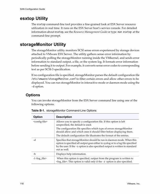
SAN Configuration Guide
118 VMware, Inc.
esxtop UtilityThe esxtop command‐line tool provides a fine‐grained look at ESX Server resource utilization in real time. It runs on the ESX Server host�s service console. For detailed information about esxtop, see the Resource Management Guide or type man esxtop at the command‐line prompt.
storageMonitor UtilityThe storageMonitor utility monitors SCSI sense errors experienced by storage devices attached to VMware ESX Server. The utility gathers sense error information by periodically polling the storageMonitor running inside the VMkernel, and sends error information to standard output, a file, or the system log. It formats error information before sending it to output. For example, it converts sense error codes to corresponding text as per SCSI‐3 specification.
If no configuration file is specified, storageMonitor parses the default configuration file /etc/vmware/storageMonitor.conf to filter certain errors and allow other errors to be displayed. You can run storageMonitor in interactive mode or daemon mode using the -d option.
OptionsYou can invoke storageMonitor from the ESX Server command line using one of the following options.
Table B-1. storageMonitor Command-Line Options
Option Description<config‐file> Allows you to specify a configuration file. If this option is left
unspecified, the default is used. The configuration file specifies which type of errors storageMonitor should allow and which ones it should filter before displaying them. The default configuration file illustrates the format of the entries.
‐d Specifies that storageMonitor should be run in daemon mode. When this option is specified all output goes either to syslog or to a log file specified by the user. If the -s option is also specified output is written to standard out as well.
‐h Displays help information.
‐l <log_file> When this option is specified, output from the program is written to <log_file>. This option is valid only if the ‐ d option is also specified.
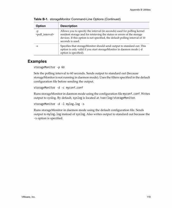
VMware, Inc. 119
Appendix B Utilities
ExamplesstorageMonitor -p 60
Sets the polling interval to 60 seconds. Sends output to standard out (because storageMonitor is not running in daemon mode). Uses the filters specified in the default configuration file before sending the output.
storageMonitor -d -c myconf.conf
Runs storageMonitor in daemon mode using the configuration file myconf.conf. Writes output to syslog. By default, syslog is located at /var/log/storageMonitor.
storageMonitor -d -l mylog.log -s
Runs storageMonitor in daemon mode using the default configuration file. Sends output to mylog.log instead of syslog. Also writes output to standard out because the -s option is specified.
‐p <poll_interval>
Allows you to specify the interval (in seconds) used for polling kernel resident storage and for retrieving the status or errors of the storage devices. If this option is not specified, the default polling interval of 10 seconds is used.
‐s Specifies that storageMonitor should send output to standard out. This option is only valid if you start storageMonitor in daemon mode (-d option is specified).
Table B-1. storageMonitor Command-Line Options (Continued)
Option Description

SAN Configuration Guide
120 VMware, Inc.
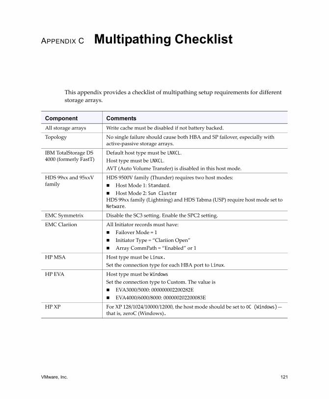
VMware, Inc. 121
APPENDIX C Multipathing Checklist
This appendix provides a checklist of multipathing setup requirements for different storage arrays.
Component CommentsAll storage arrays Write cache must be disabled if not battery backed.
Topology No single failure should cause both HBA and SP failover, especially with active‐passive storage arrays.
IBM TotalStorage DS 4000 (formerly FastT)
Default host type must be LNXCL. Host type must be LNXCL.AVT (Auto Volume Transfer) is disabled in this host mode.
HDS 99xx and 95xxV family
HDS 9500V family (Thunder) requires two host modes: ! Host Mode 1: Standard. ! Host Mode 2: Sun ClusterHDS 99xx family (Lightning) and HDS Tabma (USP) require host mode set to Netware.
EMC Symmetrix Disable the SC3 setting. Enable the SPC2 setting.
EMC Clariion All Initiator records must have:! Failover Mode = 1! Initiator Type = �Clariion Open�! Array CommPath = �Enabled� or 1
HP MSA Host type must be Linux.Set the connection type for each HBA port to Linux.
HP EVA Host type must be WindowsSet the connection type to Custom. The value is ! EVA3000/5000: 000000002200282E ! EVA4000/6000/8000: 000000202200083E
HP XP For XP 128/1024/10000/12000, the host mode should be set to 0C (Windows)� that is, zeroC (Windows).
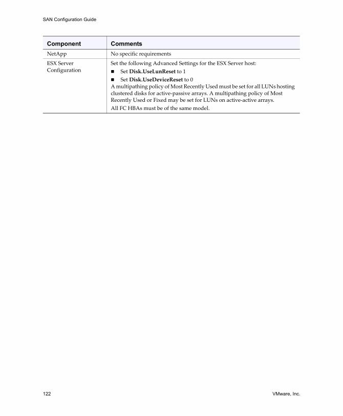
SAN Configuration Guide
122 VMware, Inc.
NetApp No specific requirements
ESX Server Configuration
Set the following Advanced Settings for the ESX Server host:! Set Disk.UseLunReset to 1! Set Disk.UseDeviceReset to 0A multipathing policy of Most Recently Used must be set for all LUNs hosting clustered disks for active‐passive arrays. A multipathing policy of Most Recently Used or Fixed may be set for LUNs on active‐active arrays. All FC HBAs must be of the same model.
Component Comments
VMware, Inc. 123
Index
Symbols* next to path 89.vmdk file 7
Aaccess
control 35data 38equalizing disk access 103
access control See masking 24active path status 89active paths 90active/active disk arrays 23, 49, 64, 90,
93active/passive disk arrays 23, 41, 49, 75,
90boot from SAN 51HP StorageWorks MSA 64path policy reset 80path thrashing 102
advanced LUN display configuration 85allocations 49applications,layered 107array-based (third-party) solution 107asterisk next to path 89authentication daemon 11auto volume transfer 62automatic volume resignaturing 59
IBM TotalStorage 64availability 115avoiding problems 98AVT 62, 102
AX100 58display problems 59inactive connections 59
Bbackups 48, 105
considerations 105solution 107third-party backup package 106
benefits 28BIOS
enabling for BFS 76enabling Qlogic HBA for BFS 74
boot BIOS prompt, enabling for BFS 76boot from CD-ROM 76boot from SAN
benefits 71boot LUN considerations 51conceptual overview 70diagnostic partitions 71Emulex FC HBA 76enabling Qlogic HBA BIOS 74ESX Server requirements 51HBA requirements 51introduction 70LUN masking 72preparing installation 71Qlogic FC HBA 74requirements 51
boot LUN 75boot LUN, selecting 75
SAN Configuration Guide
124 VMware, Inc.
BusLogicqueue depth 48SCSI controller 6
Ccables
connectivity issues 83reseating and rescan 84
caching 115can�t see LUN 82CD-ROM, booting from 76changing disk.maskLuns 87changing disk.maxLun 86changing disk.supportSparseLun 87Clariion AX100 109cluster across boxes 43cluster in a box 43cluster services 42commands, SDK 9configuration 114
options 7storage processor sense data 63
configuring hardware for SAN failoverDS4000 60
consolidated backup proxy 48CPU virtualization 5current multipathing state 88
Ddata access 37�38
(SAN) overview 39overview 38RDM 33VMFS 33
data routers 19datastores, removing 85dead paths 89
designdefining application needs 114for server failure 42
details about storage devices 81device driver options 96
Emulex 96Qlogic 96
device drivers 2diagnostic partitions 48
boot from SAN 71sharing 97
direct connect 56disabled path status 89disabling auto volume transfer 62disabling paths 91disallowSnapshotLUN 110disaster recovery 29, 116disk access, equalizing 103disk arrays
active/active 23, 49, 90, 93active/passive 23, 49, 64, 75, 90,
102zoning disk array to ESX Server 84
disk shares 37disk.maskLuns 87disk.maxLun 86Disk.SchedNumReqOutstanding
parameter 103disk.supportSparseLun 87disks, configuration options 7display problems, AX100 59distributed locking 8drivers
device drivers 96VMFS-2 103
DRS 45DS4000, configuring hardware for SAN
failover 60
VMware, Inc. 125
Index
dump partitions 48sharing 97
EEMC CLARiiON 58EMC CLARiiON AX100 58EMC Symmetrix 59
pseudo LUNs 60Emulex FC HBA
boot from SAN 76device driver options 96lpfc_linkdown_tmo 96
enableResignature 110enabling BIOS for BFS 76enabling boot BIOS prompt for BFS 76enabling paths 91�92enabling selectable boot 75equalizing disk access 103ESX Server
benefits 28introduction 2sharing VMFS 30
ESX Server and SAN, requirements 48esxtop utility 118EVA (HP StorageWorks) 66extents 8
definition 82
Ffabric 16fabric components 19failover 40, 43, 94
FAStT storage 60HBA 95I/O delay 41zones 35
failure 42FC HBA setup 49
finding information 30Fixed path policy 41, 90
path thrashing 101preferred path 92
Ggetting information 81
HHA 42hardware compatibility 4HBA 16
Emulex 76enabling Qlogic HBA BIOS for
BFS 74list of types 81Qlogic 74queue depth 104setup 49static load balancing 49timeout 95types 81
high availability 16, 115high-tier storage 41Hitachi Data Systems storage 67
microcode 67host components 19host daemon 11host type 25, 57hostd 11HP StorageWorks 64
EVA 66MSA 64XP 66
hub controller issues 66
SAN Configuration Guide
126 VMware, Inc.
II/O delay 41, 48IBM TotalStorage DS4000 60
path thrashing 64IBM TotalStorage Enterprise Storage
Systems 64indirection 32installation
preparing for boot from SAN 71SAN 52steps 53
interacting with ESX Server systems 9Inter-Switch Link 61invisible LUNs 109iSCSI 8ISL 61isolation, zoning 24issues 80
hub controller 66offline VMFS volumes 109performance 100visibility 82
KKnowledge base xii
Llayered applications 107LDAP 11levels of indirection 32Linux
host type 57profile name 64service console 11VMkernel 2
Linux Cluster host type 57list of HBA types 81
load balancing 29, 49, 93manual 93
locations of virtual machines 41locking 8
metadata updates 32Logical Volume Manager 8lower-tier storage 41lpfc_linkdown_tmo parameter 96lpfc_nodedev_tmo parameter 96LSI Logic SCSI controller 6LSILogic
queue depth 48LUN discovery, VMkernel 32LUN masking 24, 35, 83
boot from SAN 72LUN not visible
cable connectivity 83issues 83masking 83SP visibility 84zoning 83
LUNs1 VMFS volume 48allocations 49boot LUN 75can�t see 82changing number scanned 86creating, and rescan 84decisions 36disk.maskLuns 87display and rescan 32display configuration 85fewer, larger vs. more, smaller 35invisible 109masking changes and rescan 84multipathing policy 90number scanned 86
VMware, Inc. 127
Index
LUNs (continued)removing 85selecting boot LUN 75setting multipathing policy 90sparse 87
LVM 8LVM.DisallowSnapshotLUN
parameter 108LVM.EnableResignature parameter 108
Mmaintenance 29Manage Paths dialog box 92management applications 34manual load balancing 93mapping file 8masking 35
LUN not visible 83using disk.maskLuns 87
maximum HBA queue depth 104maxLun 86memory virtualization 5metadata updates 32microcode, Hitachi Data Systems
storage 67Microsoft Cluster Service 8, 28, 56mid-tier storage 41mirroring 21modular switches 19monitoring performance 100Most Recently Used path policy 90
path thrashing 101MRU path policy 90MSA (HP StorageWorks) 64MSCS 28, 56multipathing 87
path failover 22state 88
multipathing policy 90setting 91
multipathing software 33multipathing state 88multiple extents 82
NN+1 clustering 43Navisphere Express 109net-snmpd 11Netware host mode 67Network Appliance storage 67
provisioning storage 67network virtualization 5NFS 8number of extents 8number of outstanding disk requests 103
Ooffline VMFS volumes 109operating system timeout 96optimizing resource utilization 44outstanding disk requests 103
PPAM 11parameters, lpfc_nodedev_tmo 96partioning See masking 24passive disk arrays 23, 49, 64, 75, 90
path thrashing 102path failover 40
multipathing 22path failure 22
rescan 84path management 40, 93
SAN Configuration Guide
128 VMware, Inc.
path policiesFixed 41, 90Most Recently Used 90MRU 90
path policy resetactive/passive disk array 80
path status 89path thrashing 58, 101�102
IBM TotalStorage DS4000 64paths
active 90disabling 91enabling 91�92preferred 89, 92
peak period activity 114performance 98�99
issues 100monitoring 100optimizing 98removing VMFS-2 drivers 103SCSI reservations 31
physical to virtual clustering 43pitfalls 80planning for disaster recovery 116Pluggable Authentication Module 11port address 22Port_ID 22PortDownRetryCount parameter 95ports 22
configuration 61naming 22
preferred path 89, 92prioritizing virtual machines 37problems
avoiding 98hub controller 66offline VMFS volumes 109
performance 100visibility 82
processes, service console 11profile name, Linux 64
QQlogic FC HBA
boot from SAN 74device driver options 96PortDownRetryCount 95
Qlogic HBA BIOSenabling for BFS 74
queue depth 104
RRADIUS 11RAID 20
levels 20raw device mapping 8, 39, 58
mapping file 8RDM 8, 33, 39, 58
mapping file 8Microsoft Cluster Service 8
remote mirroring 21removing datastores 85removing LUNs 85removing VMFS-2 drivers 103requirements 48, 52
boot from SAN 51rescan 84
adding disk array 84LUN creation 84LUN display 32LUN masking 84reseating cables 84when path is down 84
reservationsreducing SCSI reservations 103
VMware, Inc. 129
Index
resignaturing 59IBM TotalStorage 64options 110
resolving problems 98resource utilization, optimizing 44restrictions 48
SSAN 35
arrays 30backup considerations 105basics 16components 16, 18concepts 17, 25fabric 16hardware failover 60installation considerations 52interactions 21port naming 22ports 22preparing 72preparing to install ESX Server 71requirements 48server failover 43switches 16
SAN setup 52SAN storage
benefits 28SAN storage performance, optimizing 98scanning, changing number 86SCSI controllers, device driver
options 96SCSI reservations 30SCSI reservations, reducing 103SDK 9security, zoning 24selectable boot, enabling 75
selective storage presentation See masking 24
server failover 43server failure 42server performance 99service console 2, 10
authentication 10interfaces 10processes 11
services, service console 11setup steps 53shared services, zoning 24sharing diagnostic partitions 97sharing VMFS across servers 30size of zones 35snapshot 21, 108snapshot software 106SNMP server 11software compatibility 4solutions 80SP visibility, LUN not visible 84sparse LUN support 87SPs 16standby path status 89storage arrays
configuration 114performance 98
storage choices 35storage components 20storage devices 20
details 81viewing 81
storage processors 16, 20configuring sense data 63port configuration 61sense data 63
SAN Configuration Guide
130 VMware, Inc.
storage systemsEMC CLARiiON 58EMC Symmetrix 59Hitachi 67HP StorageWorks 64Network Appliance 67
storage, tape 21storageMonitor utility 118supported devices 57switches, modular 19
Ttape devices 50tape storage devices 21testing 56third-party backup package 106third-party management applications 34timeout 95�96TimeoutValue parameter 48tips 37troubleshooting 80, 98
Uuse cases 29User groups xiiutilities
esxtop 118storageMonitor 118
VVI Client 2, 9VI Web Access 2, 9Virtual Infrastructure Client 2Virtual Infrastructure SDK 9Virtual Machine File System 8Virtual Machine Monitor 2
virtual machinesdata access 38data access on SAN 39default configuration 32equalizing disk access 103I/O delay 41locations 41prioritizing 37SAN data access 39sharing devices 12
virtual SCSI HBAs 6, 9virtualization 5
at a glance 12visibility issues 82vmauthd 11VMFS 8, 33, 35
1 volume per LUN 48creating new volume 8locking 8minimum size 8number of extents 8SCSI reservations 30sharing across ESX Servers 30
VMFS volume resignaturing 108VMFS volumes
offline 109VMFS-2 drivers 103vmhba 82VMkernel 2
configuration 97LUN discovery 32
VMM 2VMotion 28�29, 44, 49VMware community forums xiiVMware Consolidated Backup proxy 48VMware DRS 28�29, 45VMware HA 28, 42
VMware, Inc. 131
Index
volume resignaturing 59, 108TotalStorage 64
WWorld Wide Port Name 22WWPN 22, 62
XXP (HP StorageWorks) 66
Zzones
failover 35recommended size 35when to create 35
zoning 23and ESX Server 34for isolation 24for security 24LUN not visible 83shared services 24

SAN Configuration Guide
132 VMware, Inc.
VMware Update
VMware, Inc. 1
Updates for the SAN Configuration GuideESX Server 3.0 and VirtualCenter 2.0
Last Updated: June 21, 2007
This document provides you with updates to ESX Server 3.0 and VirtualCenter 2.0 version of the SAN Configuration Guide. Updated descriptions, procedures, and graphics are organized by page number so you can easily locate the areas of the guide that have changes. If the change spans multiple sequential pages, this document provides the starting page number only.
The following is a list of SAN Configuration Guide page updates in this document:
“Updates for the Layered Applications Discussion on Page 107”
“Updates for the VMFS Volume Resignaturing Discussion on Page 108”
“Updates for the Resolving Issues with Invisible LUNs Procedure on Page 109”
Updates for the Layered Applications Discussion on Page 107
The section titled “Layered Applications” has been rewritten. It now appears as follows:
Layered Applications
SAN administrators customarily use specialized array‐based software for backup, disaster recovery, data mining, forensics, and configuration testing.
Updates for the SAN Configuration Guide
2 VMware, Inc.
Storage providers typically supply two types of advanced services for their LUNs—snapshotting and replication.
Snapshotting creates space with efficient copies of LUNs that share common blocks of data. In general, snapshotting is used locally on the same array as the primary LUN for quick backups, application testing, forensics, or data mining.
Replication creates full copies of LUNs. Replicas are usually made to separate arrays, possibly separate sites to protect against major outages that incapacitate or destroy an entire array or site.
When you use an ESX Server system in conjunction with a SAN, you need to decide whether array‐based or host‐based tools are more suitable for your particular situation.
Array-Based (Third-Party) Solution
When considering an array‐based solution, consider the following points.
Array‐based solutions usually result in more comprehensive statistics. With RDM, data always takes the same path, which results in easier performance management.
Security is more transparent to the storage administrator when you use RDM and an array‐based solution because with RDM, virtual machines more closely resemble physical machines.
If you use an array‐based solution, physical compatibility RDMs are often used for the storage of virtual machines. If you do not intend to use RDM, you should check the storage vendor documentation to see if operations on LUNs with VMFS volumes are supported. Furthermore, if you use array operations on VMFS LUNs, you should carefully read the section on resignaturing.
File-Based (VMFS) Solution
When considering a file‐based solution using VMware tools and VMFS (instead of the array tools), be aware of the following points:
Using VMware tools and VMFS is better for provisioning: one large LUN is allocated and multiple .vmdk files can be placed on that LUN. With RDM, a new LUN is required for each virtual machine.
Snapshotting and replication is included with your ESX Server host at no extra cost. The file‐based solution is therefore more cost‐effective than the array‐based solution.
NOTE ESX Server systems also include a consolidated backup component, which is discussed in detail in the Virtual Machine Backup Guide.
VMware, Inc. 3
Updates for the SAN Configuration Guide
For ESX Server administrators, using ESX Server tools is easier.
ESX Server administrators who use the file‐based solution are more independent from the SAN administrator.
Updates for the VMFS Volume Resignaturing Discussion on Page 108
The section titled “VMFS Volume Resignaturing” has been rewritten. It now appears as follows:
VMFS Volume Resignaturing
ESX servers need to be able to differentiate between their VMFS volumes and use a volume signature to do so. When a VMFS volume is replicated or snapshotted, the resulting LUN copy has the same signature as the source. When two LUNs seen by an ESX Server have the same signature, the ESX Server must handle the condition to prevent downtime caused by confusion over which LUN it should be using to access the registered virtual machines. Resignaturing is a feature introduced in ESX Server 3.0 to solve this problem.
Mounting Original, Snapshot, or Replica VMFS Volumes
You can mount original, snapshot, or replica VMFS volumes on the same ESX Server host.
To mount original, snapshot, or replica VMFS volumes
1 Perform the required storage tasks:
a Make the array snapshot or replica.
b Mask or zone the snapshot or replica to the ESX Server.
2 In the VI Client, select the host in the inventory panel.
3 Click the Configuration tab and click Advanced Settings.
4 Select LVM in the left panel, then set the LVM.EnableResignature option to 1.
NOTE When a LUN needs to be resignatured, an alert appears in the vmkernel log. If you encounter such an alert, set your resignaturing options appropriately, as described in the following sections.
Updates for the SAN Configuration Guide
4 VMware, Inc.
5 Rescan the volume.
After rescan, the LUN appears as /vmfs/volumes/snap-<DIGIT>-<old-label>.
If the vmx file for any of the virtual machines or the .vmsd file for virtual machine snapshots contains /vmfs/volumes/<label or UUID>/ paths, you must change these items to reflect the resignatured volume path.
6 If necessary, set the LVM.EnableResignature option to 0 after resignaturing is complete.
Issues with Displaying the Same LUN IDs Across Hosts
Normally, a LUN appears with the same LUN ID to all hosts that access the LUN. On some arrays, however, it may not be possible to display the LUN with the same LUN ID across hosts. As a result, the ESX Server system incorrectly detects the LUN as a snapshot and places it offline.
Examples of storage arrays for which the same LUN ID may not be visible for a given LUN across hosts are Clariion AX100 and some IBM TotalStorage Enterprise Storage Systems (previously Shark Storage systems).
To resolve issues with invisible LUNs on certain arrays
1 In the VI Client, select the host in the inventory panel.
2 Click the Configuration tab and click Advanced Settings.
3 Select LVM in the left panel and set LVM.DisallowSnapshotLUN to 0 in the right panel.
4 Rescan all VMFS volumes.
After the rescan, all VMFS volumes are available.
Understanding Resignaturing Options
This section discusses how the EnableResignature and DisallowSnapshotLUN options interact and explains the three states that result from changing these options:
State 1: EnableResignature=0, DisallowSnapshotLUN=1 (the ESX Server 3.x default)
State 2: EnableResignature=1 (DisallowSnapshotLUN is not relevant)
State 3: EnableResignature=0, DisallowSnapshotLUN=0 (ESX Server 2.x behavior)
NOTE Any virtual machines on this new snapshot volume are not auto‐discovered. You must manually register the virtual machines.
VMware, Inc. 5
Updates for the SAN Configuration Guide
State 1 - EnableResignature=0, DisallowSnapshotLUN=1 (default)In this state:
You cannot bring snapshots or replicas of VMFS volumes by the array into the ESX Server host regardless of whether or not the ESX Server has access to the original LUN.
LUNs formatted with VMFS must have the same ID for each ESX Server host.
State 1 is the safest state but:
If you use Clariion AX100 with Navisphere Express, you cannot configure the same LUN ID across storage groups. You must instead use a version of Navisphere software that has more comprehensive management capabilities.
For IBM TotalStorage 8000, if you have LUNs that are not configured to present the same LUN ID to all servers, you need to either use the settings in state 3 or recreate the LUNs from scratch.
State 2 - EnableResignature=1, (DisallowSnapshotLUN is not relevant)
In this state:
You can safely bring snapshots or replicas of VMFS volumes into the same servers as the original and they are automatically resignatured.
VMFS volumes containing LUNs from IBM TotalStorage 8000 or AX100 that are not presented with the same LUN numbers to all servers effectively lose the ability to use the virtual machines stored on that VMFS volume. Avoid this situation.
State 3 - EnableResignature=0, DisallowSnapshotLUN=0
This is similar to ESX Server 2.x behavior. In this state, the ESX Server assumes that it sees only one replica or snapshot of a given LUN and never tries to resignature. This is ideal in a DR scenario where you are bringing a replica of a LUN to a new cluster of ESX Servers, possibly on another site that does not have access to the source LUN. In such a case, the ESX Server uses the replica as if it is the original.
If you have an IBM TotalStorage 8000 or AX100 that can not be configured to present the same LUN numbers to all servers for some reason, you need this setting to allow all ESX Server systems to use the same LUNs for features like VMotion, VMware DRS, and VMware HA.
Do not use this setting if you are bringing snapshots or replicas of a LUN into a server with access to the original LUN. This can have destructive results including:
If you create snapshots of a VMFS volume one or more times and dynamically bring one or more of those snapshots into an ESX Server, only the first copy is
Updates for the SAN Configuration Guide
6 VMware, Inc.
usable. The usable copy is most likely the primary copy. After reboot, it is impossible to determine which volume (the source or one of the snapshots) is usable. This nondeterministic behavior is dangerous.
If you create a snapshot of a spanned VMFS volume, an ESX Server host might reassemble the volume from fragments that belong to different snapshots. This can corrupt your file system.
Updates for the Resolving Issues with Invisible LUNs Procedure on Page 109
Step 3 of the “To Resolve Issues with Invisible LUNs on Certain Arrays” procedure incorrectly instructs you to set the LVM.DisallowSnapshotLUN parameter to 1. The correct value for the LVM.DisallowSnapshotLUN parameter should be 0.
For more information on this parameter, see “State 3 ‐ EnableResignature=no, DisallowSnapshotLUN=no” on page 110 of the SAN Configuration Guide.