eth-7786-01
DESCRIPTION
eth-7786-01TRANSCRIPT

1
LIGHTWEIGHT MAGNETIC FOOT WITH VARIABLE FORCE, FOR DOCKING/LANDING WITH MICRO-HELICOPTERS ON
RUST-COVERED WALLS IN BOILER FURNACES
WOLFGANG FISCHER, CHRISTOPH HÜRZELER, ROLAND SIEGWART Autonomous System Lab, ETH Zürich,
Tannenstrasse 3, 8092 Zürich, Switzerland
This paper describes the design, implementation and application of a lightweight magnetic foot with variable force, which was developed for docking/landing on vertical walls with a micro-helicopter in order to perform inspection tasks there; and afterwards undock to fly away without problems. Even if not being a complete climbing robot, the magnetic foot on the helicopter uses technologies which were originally developed for climbing robots, operates in an environment which is difficult to access (furnaces in coal-fired boilers) and could be useful for future climbing robots with inchworm-locomotion. By using a lightweight actuation concept based on miniature pulley-wire- transmissions, a simple and robust control strategy and a mechanical design that is well shielded against ferromagnetic dust or other types of aggressive dirt; the here presented magnetic foot with variable adhesion force achieves several advantages over previous designs – such as an excellent compromise concerning lightweight design at strong adhesion force (Fadh,max/(m*g)>100), robustness against most environmental hazards, low residual force (Fadh,max/Fred<30) and low manufacturing cost. After explaining the environment constraints, the basic concept of docking with an unmanned micro-helicopter and the requirements for the magnetic foot; a brief overview on most principles for force variation in magnetic feet is provided. This comparison is followed by the presentation of the basic design concept and its implementation in a prototype. The paper concludes with the measured values of this prototype and provides an outlook on future work and how this technology can be used in other applications.
1. Introduction
In this paper, the design and the implementation of a lightweight robot foot with variable magnetic force and its application in an unmanned helicopter is presented. The purpose of this project is to dock/land on the interior walls of a boiler furnace in a coal-fired power plant – with the goal to perform inspection tasks there. These boiler furnaces can reach heights up to 100m, at diameters between Ø20m and Ø50m (see Fig. 1-a); and usually need to be accessed for inspection two times per year. The current access method consists of placing scaffolds in the entire space (see Fig. 1-b) – an operation which normally takes more than one week and thus causes significant financial losses for the power

2
plant operator (each day of outage costs up to 1mio €). In order to decrease the total inspection time, it was proposed to access all areas with compact mobile robots instead of human workers.
Fig. 1: The furnace of a coal-fired boiler - the environment where the robot has to be applied
(a) Schematic view of the entire component, (b) Photo of a the scaffold that are usually placed during the inspection (time to set up > 1 week), (c) Detail photo of the furnace wall, showing a coal nozzle
and the boiler tubes, which are covered with a thick layer of abrasive dirt. Concerning the mobility constraints which are the most crucial for applying classical climbing robots, all parts are made out of steel that allows for ferromagnetic adhesion. However, all surfaces are usually covered with a layer of ash, dust and ferromagnetic rust. This layer can reach a thickness of up to 2mm and is very abrasive to magnetic wheels that are covered with rubber. Furthermore, the surface is not flat either, but consists of several tubes with diameters between Ø50mm and Ø200mm. In some areas there are also the coal nozzles (see Fig. 1-c) which show a relatively complex topology and thus would require the use of robots with advanced obstacle-passing capability. Concerning the applicability of non-magnetic adhesion principles, the surface is too hard for penetration with spines, too uneven for attaching with vacuum suction or artificial gecko-hairs and too irregular for grasping with modified grippers from pole-climbing-robots. However, the available space is relatively big in comparison to other power plant components and there are no problems with wind either (narrow space and wind: main limitations for flying robots).

3
2. Classical climbing robots vs. micro-helicopters + docking
Given the above mentioned environment constraints, it was decided to not use a classical climbing robot for this application – but fly to the point of interest with an unmanned micro-helicopter, land/dock on the vertical wall by using technologies similar as in climbing robots and then perform the inspection tasks with the docked helicopter (motors off, for minimizing the power consumption).
2.1. Drawbacks of using classical climbing robots
Before coming to this decision, the possibilities for moving in this environment with classical climbing robots have been analyzed. First test have been done with a simplified version of the MagneBike [1], which rolls on rubber-covered magnetic wheels and implements several innovative mechanisms for dealing with difficult combinations of obstacles. After a few cm, this robot already failed, as the ferromagnetic rust was sticking to all parts of the magnetic wheel – not only destroying the rubber but also penetrating into the gears. For this reason, the idea to use magnetic wheeled robots with additional mechanisms for passing specific obstacles [1-4] had to be rejected very soon. The alternative of using magnets in the structure instead of magnetic wheels [5], which is slightly more dirt-resistant than magnetic wheels, had to be rejected as well, as these robots usually do not achieve the required mobility for the difficult topology that is formed by the uneven surface of several tubes and the specific geometry of the coal nozzles. Alternatives locomotion and adhesion-principles have been considered as well: Legged [6] or inchworm-type-robots [7-9], feet that grasp on features [8, 9], spines [10] or other principles for adhesion. However, they were not analyzed into more detail, as the typical speed of these robots is relatively slow; and robust industrial solutions are not commercially available yet.
2.2. Basic concept: Micro-helicopter with docking mechanism
Given the above mentioned limitations of classical climbing robots and the impressive advances of recently developed micro-helicopters regarding payload capability, reliability and user-friendliness; the focus of this project was set to combine both approaches – by using the most advanced technology in the field of micro-helicopters and by docking with an innovative magnetic foot of variable adhesion force. A similar approach has been realized by Roberts et al. [14] for docking to the ceiling. However, docking operations to vertical walls have not been realized yet to our best knowledge. Fig. 2 shows the concept of
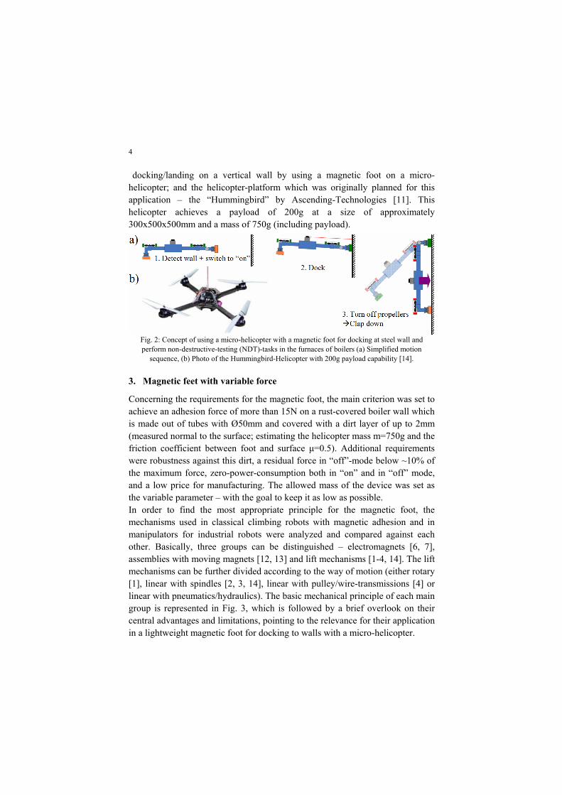
4
docking/landing on a vertical wall by using a magnetic foot on a micro-helicopter; and the helicopter-platform which was originally planned for this application – the “Hummingbird” by Ascending-Technologies [11]. This helicopter achieves a payload of 200g at a size of approximately 300x500x500mm and a mass of 750g (including payload).
Fig. 2: Concept of using a micro-helicopter with a magnetic foot for docking at steel wall and perform non-destructive-testing (NDT)-tasks in the furnaces of boilers (a) Simplified motion
sequence, (b) Photo of the Hummingbird-Helicopter with 200g payload capability [14].
3. Magnetic feet with variable force
Concerning the requirements for the magnetic foot, the main criterion was set to achieve an adhesion force of more than 15N on a rust-covered boiler wall which is made out of tubes with Ø50mm and covered with a dirt layer of up to 2mm (measured normal to the surface; estimating the helicopter mass m=750g and the friction coefficient between foot and surface µ=0.5). Additional requirements were robustness against this dirt, a residual force in “off”-mode below ~10% of the maximum force, zero-power-consumption both in “on” and in “off” mode, and a low price for manufacturing. The allowed mass of the device was set as the variable parameter – with the goal to keep it as low as possible. In order to find the most appropriate principle for the magnetic foot, the mechanisms used in classical climbing robots with magnetic adhesion and in manipulators for industrial robots were analyzed and compared against each other. Basically, three groups can be distinguished – electromagnets [6, 7], assemblies with moving magnets [12, 13] and lift mechanisms [1-4, 14]. The lift mechanisms can be further divided according to the way of motion (either rotary [1], linear with spindles [2, 3, 14], linear with pulley/wire-transmissions [4] or linear with pneumatics/hydraulics). The basic mechanical principle of each main group is represented in Fig. 3, which is followed by a brief overlook on their central advantages and limitations, pointing to the relevance for their application in a lightweight magnetic foot for docking to walls with a micro-helicopter.

5
Fig. 3: Comparison of the three basic mechanisms that are used in magnetic feet with variable force,
pointing to their core advantages (+), their limitations (-) and the importance in the here analyzed application concerning a lightweight docking-mechanisms for micro-helicopters
Given the disadvantages of electromagnets (permanent need for power) and assemblies with a moving magnet (relatively bad force-mass-ratio compared to normal magnets), using a lift mechanism looked the most promising – ideally with a pulley-wire-transmission instead of a spindle in order to save mass. For this reason, this solution was chosen for the final concept.
4. Design, prototype implementation and test
The basic mechanical design of the magnetic foot is represented in Fig. 4-a. As already explained in the last section, it uses an actuation principle which is based on a miniature pulley-wire-transmission for keeping the necessary mass for the actuators and gears as low as possible. As it can be seen in the calculation at the bottom of the image, a pulling force of more than 200N can be achieved – by using a gear-motor of only 5g. For moving the magnet into the other direction, an elastic rubber spring is used – at relatively low force, as it only has to overcome the friction losses and a few grams of mass. In the first version, a standard ring magnet was used (NdFeB 35, Ø15/5x6mm, 10g). In the final version, this magnet will be replaced by an assembly which is optimized for high adhesion force on curved surfaces with large dirt gaps (e.g. several

6
cube magnets in Halbach-configuration). In order to protect the device from ferromagnetic rust particles, a dirt-protection out of a thin rubber foil (thickness: 0.5mm) is placed at the contact area towards the environment. For guiding the motion of the magnet, linear slide guiding elements are used – similar as in our previous robot for gas tank inspection [3].
Fig. 4: Detailed design of the magnetic foot with variable adhesion force (a) Mechanical design for
achieving high pulling forces at low mass, (b) Control strategy based on 2 diodes and 2 end-switches – which only requires a binary information coming from the main control board.
For electrically controlling the motion, a circuit with two end-switches and two diodes has been chosen (see Fig. 4-b). With this circuit, the motors always switch off automatically at the end-positions – requiring a minimal control effort coming from the helicopter (only binary information – on or off). Based on this design concept, a prototype has been implemented and tested on several surfaces, with the following results (forces measured perpendicular to the surface): 42N on plain steel surfaces, 30N on rusty tubes with few dirt, 16N on the “worst-case”-tubes with a dirt layer thickness of 2mm, <0.5N residual force on all surfaces, 5sec switching time, 22g mass. These values were already sufficient for fulfilling the preliminary specifications given at the beginning of the project. However, for the final design a bigger helicopter will be chosen (500g payload, 1.5kg of total mass). Furthermore, also the dirt layers can be even thicker (up to 5mm). For this reason, the next version will implement a slightly stronger magnet assembly – approximately 20g and in a configuration which is optimized for curved surfaces with large dirt gaps.

7
Fig. 5: Prototype tests (a) Adhesion on a dirty tube,
(b) Adhesion on a clean tube, (c) Residual force in “off”-position.
5. Conclusion and outlook to future work
In this work, a lightweight magnetic foot has been developed and successfully implemented as a prototype. By choosing innovative approaches for the actuation principle (pulling a permanent-magnet with a miniature pulley-wire-transmission) and for the electric control; this foot achieves extraordinary performance regarding its low mass (22g) and its simple control (only needs a binary information). The functionality of this foot – regarding its adhesion force on dirty surfaces and switching to low force – has been proven successfully in real experiments. A comprehensive overview on the most frequently used principles for force-variation in magnetic feet, and their core advantages and limitations has been provided as well. The foot will be used as a landing/docking device for a micro-helicopter, which is planned for inspecting the furnaces of coal-fired power plants. Both the steps towards controlling the micro-helicopter for this operation and the final changes on the magnetic foot are currently under development. Apart from this application, a slightly modified version of the here presented magnetic foot could be used in classical climbing robots with legged or inchworm locomotion [6-10] as well – taking advantage of the excellent ratio between adhesion-force and mass, the simple control and the good scalability of the system.

8
References
1. F. Tache, W. Fischer, G. Caprari, R. Moser, F. Mondada, R. Siegwart, "Magnebike: A Magnetic Wheeled Robot with High Mobility for Inspecting Complex Shaped Structures", Journal of Field Robotics, Vol. 26-5, May 2009, 453-476.
2. M. Suzuki, T. Yukawa, Y. Satoh, H. Okano, “Mechanisms of Autonomous Pipe-Surface Inspection Robot with Magnetic Elements”, 2006 IEEE International Conference on Systems, Man, and Cybernetics, October 8-11, 2006.
3. W. Fischer, F. Tache, R. Siegwart, "Magnetic Wall Climbing Robot for Thin Surfaces with Specific Obstacles", 6th International Conference on Field and Service Robotics (FSR), 2007.
4. W. Fischer, G. Caprari, R. Siegwart, R. Moser, “Locomotion System for a Mobile Robot on Magnetic Wheels With Both Axial and Circumferential Mobility but only 8mm Height, for Generator Inspection With the Rotor Still Installed”, Transactions on Industrial Electronics, provisionally accepted for publication, 2010.
5. S. Mondal, A. Brenner, J. Shang, B. Bridge, T. Sattar, “Remote Automated Non-Destructive Testing (NDT) Weld Inspection on Vertical Surfaces”, Proc. of the 11th International Confer-ence on Climbing and Walking Robots (CLAWAR), September 2008.
6. L. Fortuna, A. Gallo, G. Giudice, G. Muscato, "ROBINSPEC: A Mobile Walking Robot for the Semi-Autonomous In-spection of Industrial Plants", in Robotics and Manufacturing: recent trends in research and applications, Vol. 6, ASME PRESS New York (USA), March 1996.
7. Kotay, K. and Rus, D. 1996. Navigating 3d steel web structures with an Inchworm robot. In Proc. of the 1996 International Conference on Intelligent Robots and Systems, Osaka, 1996.
8. J. Maempel, E. Andrada, H. Witte, “INSPIRAT – towards a biologically inspired climbing robot for the inspection of linear structures”, Proc. of the 11th Int. Conference on Climbing and Walking Robots (CLAWAR), September 2008.
9. M. Tavakoli, L. Marques, A. de Almeida, "Self Calibration of Step-by-Step Based Climbing Robots”, The 2009 IEEE/RSJ International Conference on Intelligent Robots and Systems, October 11-15, 2009.
10. S. Kim, A. Asbeck, M. Cutkosky, W. Provancher, “SpinybotII: Climbing Hard Walls with Compliant Microspines”, Int. Conf. On Advanced Robotics, 2005.
11. Ascending Technologies GmbH, “Professional line AscTec Hummingbird, product information www.asctec.de/main/index.php?id=4&pid=2&lang=en&cat=pro
12. Schmalz GmbH, “Magnetic grippers SGM”, Product brochure found on http://www.schmalz.com/np/pg/produkte?hier=155-3886-3891-4009&lng=en
13. P. Underwood, F. Kocijan, “Switchable permanent magnetic device”; Patent US 6,707,360, The Aussie Kids Toy Company, March 16, 2004.
14. J. Roberts, J. Zufferey, D. Floreano, “Energy Management for Indoor Hovering Robots”, Proc. of the IEEE International Conference on Intelligent Robots and Systems (IROS), 2008.