eudet, oct8 - 10, 2007 ivo polak, iop prague1 a fast led driver prototype for hcal calibration eudet...
TRANSCRIPT

EUDET, OCT8 - 10, 2007
Ivo Polak, IoP Prague 1
A fast LED driver prototype for HCAL calibration
EUDET annual meeting at Ecole Polytechnique, Palaisau

EUDET, OCT8 - 10, 2007
Ivo Polak, IoP Prague 2
Proposal for calibration system
• New LED driver with reduced crosstalk
• A tunable calibration light in the range 0 to 100MIP
• Simplification of the optical system: one LED -> one side emitting fibre, one row of scintillator tiles
• PIN photo diode, do we need them?
EUDET, OCT8 - 10, 2007
Ivo Polak, IoP Prague 3
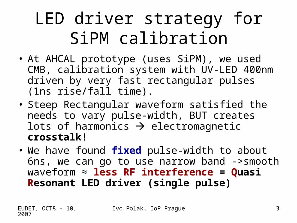
LED driver strategy for SiPM calibration
• At AHCAL prototype (uses SiPM), we used CMB, calibration system with UV-LED 400nm driven by very fast rectangular pulses (1ns rise/fall time).
• Steep Rectangular waveform satisfied the needs to vary pulse-width, BUT creates lots of harmonics electromagnetic crosstalk!
• We have found fixed pulse-width to about 6ns, we can go to use narrow band ->smooth waveform ≈ less RF interference = Quasi Resonant LED driver (single pulse)
EUDET, OCT8 - 10, 2007
Ivo Polak, IoP Prague 4
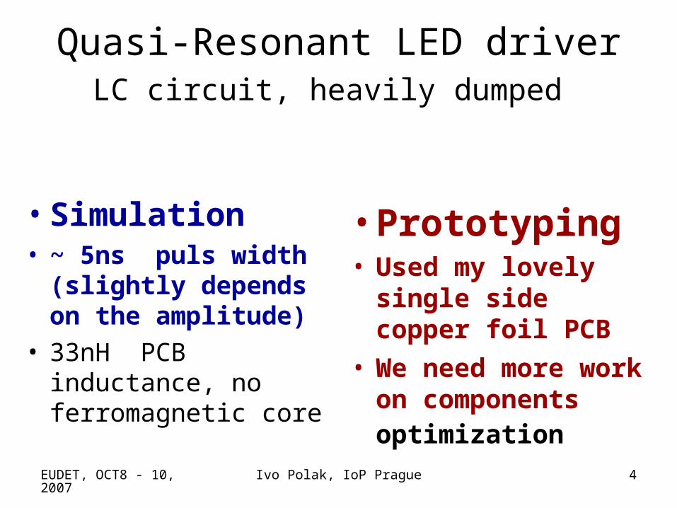
Quasi-Resonant LED driverLC circuit, heavily dumped
• Simulation• ~ 5ns puls width
(slightly depends on the amplitude)
• 33nH PCB inductance, no ferromagnetic core
• Prototyping• Used my lovely single
side copper foil PCB
• We need more work on components optimization

EUDET, OCT8 - 10, 2007
Ivo Polak, IoP Prague 5
QR LED driver Simulation
oscilloscope oscilloscope

EUDET, OCT8 - 10, 2007
Ivo Polak, IoP Prague 6
Simulation at 1.5V amplitude
• XSC1: • Upper trace - sync pulse• Lower trace – voltage at LED
hot end
• XSC2: Lower trace LED current
EUDET, OCT8 - 10, 2007
Ivo Polak, IoP Prague 7
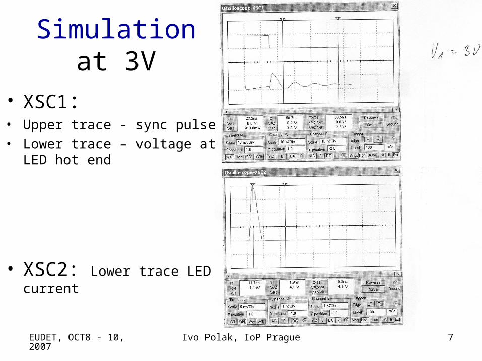
Simulation at 3V
• XSC1: • Upper trace - sync pulse• Lower trace – voltage at LED
hot end
• XSC2: Lower trace LED current

EUDET, OCT8 - 10, 2007
Ivo Polak, IoP Prague 8
Prototype of QR LED driver

EUDET, OCT8 - 10, 2007
Ivo Polak, IoP Prague 9
LED current waveform (GRN) a=3
EUDET, OCT8 - 10, 2007
Ivo Polak, IoP Prague 10
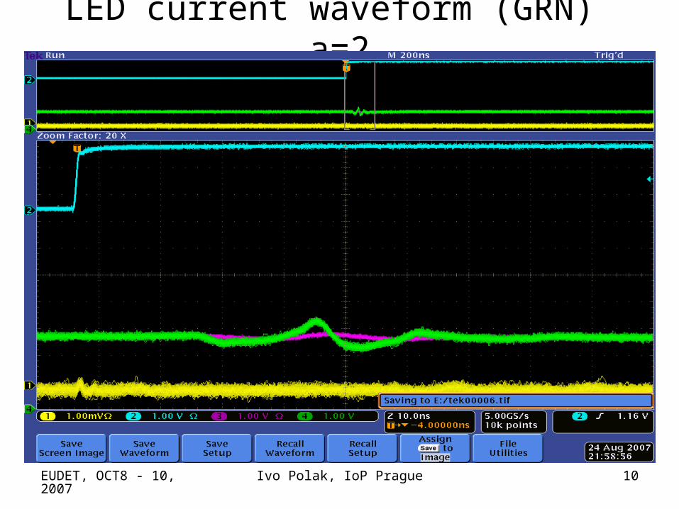
LED current waveform (GRN) a=2

EUDET, OCT8 - 10, 2007
Ivo Polak, IoP Prague 11
LED current waveform (GRN) a=1
EUDET, OCT8 - 10, 2007
Ivo Polak, IoP Prague 12
Last tests, more power on LED
• We see response of PIN photodiode at oscilloscope
• Amplitude up to 2mVpeak @ 50 Ω
EUDET, OCT8 - 10, 2007
Ivo Polak, IoP Prague 13
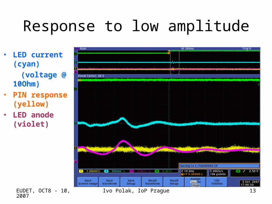
Response to low amplitude
• LED current (cyan)
(voltage @ 10Ohm)
• PIN response (yellow)
• LED anode (violet)

EUDET, OCT8 - 10, 2007
Ivo Polak, IoP Prague 14
Response to middle amplitude
EUDET, OCT8 - 10, 2007
Ivo Polak, IoP Prague 15
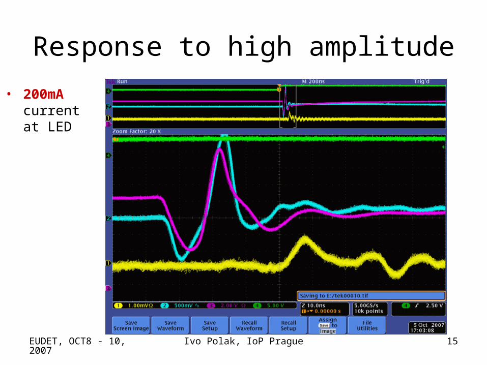
Response to high amplitude
• 200mA current at LED
EUDET, OCT8 - 10, 2007
Ivo Polak, IoP Prague 16
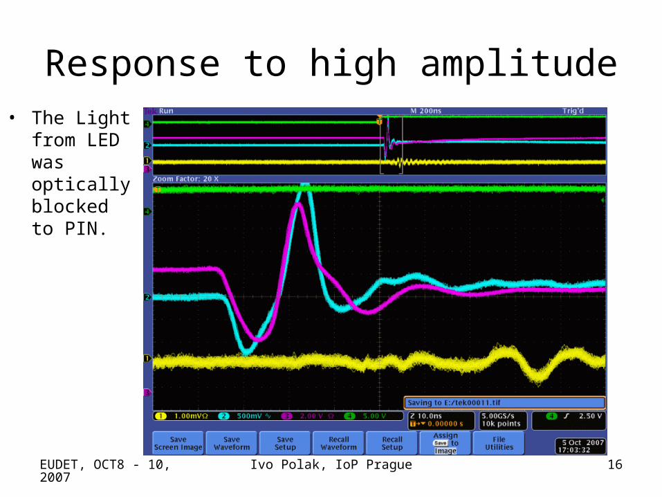
Response to high amplitude• The Light
from LED was optically blocked to PIN.

EUDET, OCT8 - 10, 2007
Ivo Polak, IoP Prague 17
Conclusion• QR LED driver is very promising technique
to reduce Electro-Magnetic-Interferences• PCB of the two-channel QR LED driver is
being designed now• End of October - PCB will be assembled –
ready for tests• November – summary report to EUDET• November – measurements of light
transfer in side-emitting fibres