evaluation of the electrotape distance-measuring …
TRANSCRIPT
Evaluation of the Electrotape Distance-Measuring Device by the Texas Highway Department ROBERT C . RUTLAND
Supervising Designing Engineer, Highway Design Division Texas Highway Department
•THE PHOTOGRAMMETRY Section within the Texas Highway Department is a subdivision of the Highway Design Division and functions as a service organization to the 25 District offices located throughout the State. Requests for photogrammetrically compiled maps and for furnishing related products originate in the various Districts and are forwarded to this section in the Austin office for accomplishment. At present, six stereoscopic photogrammetric instruments are utilized for compiling maps and making measurements in the highway surveying programs.
The duties and responsibilities involved in establishing sufficient and accurate field control necessary for doing the mapping by photogrammetric methods rests with the District making the request, while the Photogrammetry Section acts as consultant and advisor for the field control surveying .
Depending on the intended utilization of the maps, the basic field control usually consists of a second- or third-order horizontal traverse and a third-order vertical network. For highway location and design programs in rural areas the third-order traverse is considered sufficient, but when it is intended as a control base for preparing deed descriptions and for compiling other right-of-way data, and for designing facilities in urban areas through use of dimensions scaled or calculated from plane coordinates of details on the maps, second-order horizontal accuracy is required in the basic control.
The attainment of second-order accuracies using ordinary field survey methods is extremely time consuming and expensive and proof of such attainment must be provided, either by surveying closed traverse loops or by making closure ties to existing station markers of known accuracy. Texas' land area, being as extensive as it is, prohibits the inclusion of ties to existing station markers in the planning of every survey project. Monuments at station markers are utilized at every point of existence , but in some cases to make traverse ties to the beginning and from the end of a particular survey project to the monuments of existing station markers would require as long, if not longer, than the traverse of the survey project itself, and therefore would be economically unjustifiable.
A traverse loop resulting in closure back to the beginning point adequately serves the proof postulation of accuracy; however, it does not present an efficient or economical solution to the problem. The inherent difficulties involved in a normal high-order transit and tape survey would seem to discourage the use of such procedures in any, but the most essential, control survey projects. The amount of time and money necessary to conduct a second-order transit and tape survey always discourages the resident engineer from undertaking the establishment of county or district-wide networks of basic control. Given certain highways to construct and maintain and a specific amount of money to defray the costs of accomplishing work, it is understandable why the resident engineer hesitates to undertake a program of surveying basic area control on an area basis when such an undertaking offers no immediate tangible results for the separate highway surveys which have to be made in scattered places and in successive years. The cost of property and the intricacies of intercity expressways allow the urban engineer to establish control survey networks throughout his area with the resultant costs assignable on an easily recognized need basis. Property values in rural
Paper sponsored by Committee on PhotograJllll1etry and Aerial Surveys .
15
16
areas, however, do not require as great an accuracy. Consequently, control survey networks in rural areas are not so easily justified.
Even in urban areas where justification is not a problem, actual execution of basic control surveys can be difficult in the extreme. Traffic in the more congested sections almost prohibits the use of second-order taping, except during short and inconvenient periods of time. Triangulation is often used in these cases, but problems of position location and building obstructions often present difficulties which involve elaborate and therefore expensive solutions which do not readily lend themselves to highway survey project requirements.
As a partial solution to the problems of making accurate basic control surveys in urban and rural areas the Texas Highway Department decided to purchase an electronic distance-measuring device. Investigations were conducted to determine the instrument most suited for control surveying in Texas according to the intended use. The investigations were made by discussions with and by study of published reports of photogrammetric firms, consulting engineering firms, and governmental agencies.
The three major units on the market at the time were carefully studied. Particular attention was given to the size and weight of the instruments and availability of maintenance services and the method of instrument operation. Based on these three considerations, it was decided to purchase the Electrotape.
Because complete and detailed information concerning the Electrotape instrument (insofar as its regular field performance is concerned) was not readily available, it was decided to request participation of the U. S. Bureau of Public Roads in a research project designed to determine the device's suitability for making basic control surveys needed in the photogrammetric compilation of maps, and measurement of cadastral data and profile and cross-sections, and also its utility as an adjunct to regular highway surveying instruments.
Such assistance was granted under the stipulations of a research proposal outlining the procedures to be employed and with the end product consisting of a complete report of the methods used, problems encountered, and accuracies and limitations involved in the utilization of the device under varying conditions.
OPERATION OF THE ELECTROTAPES
A Cubic Corporation representative delivered the instruments and remained several days to instruct operators and to acquaint personnel with the ordinary procedures of maintaining the equipment in operation. Field and classroom instructions (with an emphasis on practical applications rather than operational theory) were given, inasmuch as it was planned to allow the factory to service the instruments during the extent of the warranty period of one year. Two engineers were trained as operators who were to conduct the initial portion of the evaluation program and who would also serve as instructors when the instruments were subsequently used in a program of basic control surveying. The simplicity of operation of the units was such that the instruction period was comparatively short.
The control panel of the Electrotape units has been specifically designed for ease of operation and for the rapid and logical completion of the sequence of manipulations necessary in obtaining the distance-measurement data. A method of instrument operation (in step-by-step form) may be obtained from the Texas Highway Department.
CREW PERSONNEL
Originally the makeup of the crew consisted of two operators from the Austin office with the remainder of the personnel being furnished by the district offices. This practice was initiated in order to create an opportunity to train operators in the field and thereby provide the research program with the data necessary to draw conclusions as to the ease, or lack of it, with which the instruments could be properly operated by inexperienced personnel. As the program developed, a third member was added to the crew from the Austin office to provide an extra man who could be made available for instruction and explanation as the work progressed uninterrupted.
17
The overall electrotape surveying crew size will, of course, vary according to individual project needs. It has been concluded, however, that a four-man crew is sufficient when the objective pertains to making linear measurements. If angles are to be measured or elevations established concurrently while using the Electrotape, the survey crew size must be increased accordingly. If elevations or angular data are• necessary, a full five-man crew is recommended.
The capital investment in the Electrotapes and the need to attain as near constant operation as possible make addition of the units to a regular survey crew, complete with operators, necessary ( whenever possible) so the instruments and operators can be withdrawn for reassignment as the work demands without unduly disrupting the activities of the remaining personnel.
ACCOMPANYING EQUIPMENT
The electronic distance-measuring devices are completely new and different types of surveying instruments which may, in time, alter most present methods of establishing basic control in the field. It is not surprising, and it is only logical to assume, the employment of such instruments will require changes in the usages and types of accessorial equipment.
The horizontal distance accuracy now easily obtainable is almost completely wasted unless the supporting instruments are capable of producing results of at least a comparable nature. The attainment of these results requires a theodolite which indicates angular measurements directly to one second of arc and a precision level with equal capabilities.
The two-way communication system built into the Electrotape units is completely adequate and very practical. The communication facilities are usable, however, only after the Electrotapes have been set up and turned toward one another. During the remaining periods of time, it is beneficial to establish some sort of oral communication to facilitate orientation, lines of sight, point location, and the like. In addition, the nonoperating party chief should have some method of advising survey crew members about the possible future setups and the progress of the work in general. Small two-way portable radios provide an excellent means of fulfilling this requirement, and three such units are considered adequate for an average crew.
The small nickel-cadmium batteries supplied with the Electrotape have an average life of approximately two hours per recharge. It has, therefore, been necessary to supply an additional two batteries for use during recharging cycles and for work in areas where the terrain demands walking to and from a site.
Binoculars have proved to be an invaluable adjunct to the equipment to check lines of sight and to identify obstructions in the line between points for which the distance is to be measured and in visually locating the companion Electrotape situated at a long distance away. Thus, seven power, 50-mm binoculars were provided each Electrotape operator.
In addition to the small nickel-cadmium batteries, two regular automotive 12-v batteries are utilized for setups where vehicular transportation is possible. The batteries normally installed in the automobiles assigned to the crew have been used as a power source in the past, but experience has proved this practice to be inconvenient and inefficient because it demands that the automobile remain at one of the instrument sites as long as measurements are being made and prevents the use of the vehicle for reconnaissance or for shuttling between the units. A fully charged automobile battery will last approximately eight hours or through two normal working days before it requires recharge.
Survey traverses on the order of those measured by use of these electronic instruments should always be referenced to permanent monuments in the previously established network of basic control surveys of known accuracy or to the position of celestial bodies at some instant of time to preserve the effort and expense expended. Where monuments are inaccessible or nonexistent, observations on Polaris, a satellite or other foreign reference points are necessary and convenient. In such determinations, the exact time must be known to an accuracy beyond the capabilities of ordinary
18
mechanisms. The National Bureau of Standards operates powerful radio transmitters, which indicate by electronic tones, time intervals based on an atomic clock and these transmissions are discernible through a radio receiver on frequencies of 2. 5, 5, 10 and 15 megacycles. The use of a portable receiver is recommended.
The accuracies obtained by the Electrotape present a problem in field calculations. Multiplication and division of eight-digit figures become commonplace in checking the work in the field and require furnishing the survey crew with a simple field calculator . Slide rule or manual calculating is neither fast nor accurate enough to keep pace with the progress of the crew.
In checking the calibration of the instruments and in performing short-distance measuring, an invar or lovar tape, work tapes, chaining thermometers, tension handles , and related equipment are required. Of course, the typical surveying accessories are provided, but they are common to any survey crew and cannot be considered out-of-the-ordinary equipment .
DESCRIPTION OF SEVERAL PROJECTS
It has been the primary intention of the Texas Highway Department in accomplishing the objectives of this research project to test the instruments in as many diverse types of conditions as possible . Thus far, experience has ranged from the use of the Electrotapes in making an ordinary highway survey to the setting and measuring the position of recoverable reference monuments to a high degree of accuracy. The following is a partial listing of the projects conducted in this research:
US 59 in Fort Bend County
This is a combination of reconstruction on existing location and construction on new location of a highway traversing approximately 45 miles of Fort Bend County in southeast Texas .
Its value in the program lies in the different conditions encountered along the route. It offers flat open terrain, densely wooded areas, a major river crossing, and as mentioned before, both existing and new locations .
The Highway Design Division in Austin of which the Photogrammetry Section is a part was requested to furnish the Houston District Office with planimetric and topographic maps at a scale of forty feet to the inch. It was decided to utilize the Electrotapes in the establishment of second- order control to be used as a basis for compiling the maps. Using U. S. C. and G. S. monuments as reference points, an Electrotape traverse was measured along the proposed facility throughout the full length of the project. Iron pins were set in such a manner as to locate the P . I. 's of the alignment and P. 0. T. 's were established at an interval of approximately 2,000 feet where intervisibility would permit .
The Electrotapes were used to determine distances between the P. I. 's and P. 0. T. 's and precise angular measurements were made at all tangent intersections to form a basic traverse with ties to existing U. S. C. and G. S. monuments as often along the project as existence of the monuments would allow.
The entire 45 miles of traverse consisted of four segments each of which began and ended on monuments of existing survey control points. Closure errors were calculated for each segment as if they were independent of one another and for the entire traverse as a single unit. A 10-sec theodolite was used for angular measurements at the P . I. 's and no special effort was made to secure unusual accuracies . Differences in elevations were obtained either by measurement of vertical angles or by differential leveling. Total errors of closure were as follows: Segment 1-1/ 14, 000; Segment 2-1/ 90, 000; Segment 3-1/20, 000; Segment 4-1/ 16, 000; Segment 1 through Segment 5-1/ 20, 000; and total number of Electrotape measurements-108.
Subsequent investigations revealed angular errors which, when corrected, improved the accuracies obtained.
1-45 in the City of Dallas
The project was located in a heavily congested urban area of one of the larger metropolitan centers. The project was selected primarily to study the effect of moving
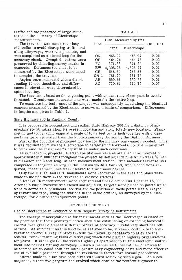
traffic and the presence of large structures on the accuracy of Electrotape measurements.
The traverse was measured along sidewalks to avoid disrupting traffic and along alleyways, wherever possible, and was completed as a closed loop for the accuracy check. Occupied stations were preserved by chiseling survey marks in concrete. Distances too short to be measured by the Electrotape were taped to complete the traverse.
Angles were measured with a direct reading 10-sec theodolite, and differences in elevation were determined by spirit leveling.
Line
ON OP FG EW CB
CB-1 AB AC
TABLE 1
Dist. Measured by (ft)
Tape
465.92 464.76 371. 33
4,308.28 536.39 781. 70 550. 66 770. 82
Electrotape
465. 97 464.78 371.26
4,308.27 536. 38 781. 76 550.65 770.75
Diff. (ft)
+0.05 +0.02 -0.07 -0.01 -0.01 +0.06 -0.01 -0.07
The traverse closed on the beginning point with an accuracy of one part in twenty thousand. Twenty-one measurements were made for the entire loop.
19
To complete the test, most of the project was subsequently taped along the identical courses measured by the Electrotape to serve as a basis of comparison. Differences in lengths are given in Table 1.
State Highway 206 in Eastland County
It is proposed to reconstruct and realign State Highway 206 for a distance of approximately 20 miles along its present location and along totally new location. Planimetric and topographic maps at a scale of forty feet to the inch together with crosssections were requested from the Photogrammetry Section by the District Engineer.
Part of the corridor of proposed location for the highway was densely wooded. Thus it was decided to utilize the Electrotape in establishing horizontal control in an effort to determine the instrument's capabilities under such conditions.
As in preceding projects, Electrotape stations were established at an interval of approximately 2,000 feet throughout the project by setting iron pins which were % inch in diameter and 3 feet long, at each measurement station. The meander traverse was comprised of tangents as long as the location would allow and, where conditions required, measurement lines were cleared to a minimum degree.
Only two U.S. C. and G. S. monuments were recovered in the area and plans were made to include them in the traverse as closure stations.
A total of 75 measurements were required and final closure was 1 part in 18,000. After this basic traverse was closed and adjusted, targets were placed on points which were to serve as supplemental control and the position of these points was surveyed by transit and tape, using the stations in the basic control, as surveyed by the Electrotape, for closure and adjustment points.
TYPES OF SURVEYS
Use of Electrotape in Conjunction with Regular Surveying Instruments
The concept of acceptable use for instruments such as the Electrotape is based on the premise that their primary function should be establishing or extending horizontal control over great distances with high orders of accuracy in relatively short periods of time. As important as this function is realized to be, it cannot contribute to a diversified control surveying program with the flexibility necessary to alleviate the tedious, time-consuming tasks of surveying which have plagued high,vay organizations for years. It is the goal of the Texas Highway Department to fit this electronic instrument into normal highway surveying in such a manner as to permit new practices to be formed which could result in lower preliminary engineering costs and more effective use of available personnel through the revisions in theretofore normal procedures .
Efforts made thus far have been directed toward achieving such a goal. As a consequence, a tentative program has evolved which enables the resident engineer to

20
produce second-order surveys for all types of projects without the necessity of employing expensive techniques usually associated with transit and tape methods. Basically the program consists of the following steps:
As it becomes necessary to establish ground control for compiling maps by photogrammetric methods, a preliminary study is made in office and field of the area to determine the existence of referenced monuments, either Federal or State, and the most economical route the control surveying should follow. When this determination is made, a series of semi-permanent survey markers are set throughout the project in areas outside the anticipated limits of future construction. A theodolite is used in measuring position of the markers, and tangents are made as long as conditions permit. These markers, whether at points of intersection or points on tangent are spaced at an interval of approximately two thousand feet, and usually consist of reinforcing rods three to four feet long driven below the natural surface of the ground. Monuments marking existing control points which can be recovered in the area are included in the traverse and efforts are made to begin and end the surveying on markers of control points set by Federal agencies.
Electrotape measurements are made between the iron pins and to all existing monuments which can be recovered. The field notes of the basic traverse thus measured are reduced and the errors of closure are adjusted.
Assuming the topographic maps will be compiled at the normal scale of forty feet to the inch for design purposes, placement location for the targeted control points is established by typical chaining methods at an interval of three hundred feet. No effort is made to employ precision methods in the taping processes, since adjustments are subsequently made to the taped distances between each marker by use of the Electrotape measurements. In effect, the project traverse consists of numerous taped traverses none of which are longer than 2, 000 feet. In this manner, taping errors are not allowed to accumulate and overall accuracies are always as great or greater than secondorder accuracy.
The time expended (and therefore the cost) of such an operation is no greater than is normally required to make such surveys without the Electrotape, and yet the accuracies are usually much more dependable.
When the mapping operations are completed, the designed highway alignment is accurately plotted by coordinates on the map sheets, critical points of control along the centerline are identified by coordinates and established in the field using the iron pin markers as reference points, the position of each of which had been measured by use of the Electrotape. In this manner, the field notes for the centerline can be completed in the office permitting more attention to be given to particularly critical sections of the highway location which will be classified as priority areas during construction. Furthermore, construction staking is not dependent on long and involved transit-tape surveys, but may be accomplished in short segments, beginning at any point throughout the highway project during any phase of construction.
Use of Electrolape as a Separate Surveying Instrument
The Electrotape is well suited to function independently. Its primary independent use is in checking taped distances and in transferring control surveying measurements over long distances. Traverses measured by use of transit and tape in which closure errors indicate blunders exist are normally checked by remeasuring until discrepancies appear in comparative measurements. This can be a long and involved process requiring the time of experienced personnel whose services can more productively be utilized elsewhere. Using two Electrotape units and operators, the tangents of a survey can be checked in much less time than is otherwise required and at much less expense.
Another method of utilizing the Electrotape instruments as a separate unit consists in the making of a straight-line survey. For example, the control layout for a long structure for a river crossing is usually measured by triangulation with actual measurement along the centerline never having been made directly in the field. These crossings are very often over rugged topography where accurate taping is virtually impossible, and locations containing angles are usually measured and referenced using angle-measuring instruments.
21
The Electrotape is well suited to check the horizontal distances thus determined and proof of the instrument's measurement accuracy is provided from closed loops which are a part of these checks. One Electrotape unit is positioned on the centerline where obs ervations can be made to points along as much of the alignment as is possible. This primary position should, for maximum effectiveness, be as near one end of the proposed structure as conditions will permit. The second Electrotape unit is moved from point to point along the centerline, and measurements are made between it and the first unit until the resultant s eries of measurements forms a distance between marked points which is equal to or exceeds the entire length of the structure. Variations of this simple procedure produce several measured segments of the centerline, the total of which can be compared to the overall length to form a straight- line closed traverse. The points selected t o comprise the end of each segment may be those between which distances were already measured by other means or may be points at which markers were set at random as the Electrotape survey progressed. In either case, the distance measure ments checked or initially measured can be used with full confidence in their accuracy and, if necessary, the position of the markers established thereby can form the basis for referenced control points to be use d during construction.
Use of the Electrotape for Trilateration
The extension of horizontal control measurements over relatively long distances with a minimum of delay and expense appears to be one of the main benefits t o be derived from use of an elect ronic distance-measuring device. As mentioned, it has been the primary purpose of the Texas Highway Department to study methods of utilizing the Electrotape in normal highway surveying. As this study continues, however, it becomes more obvious that it will be necessary to examine all potentials of the Electrotape to accomplish a complete and thorough evaluation of its multiple uses.
To realize the full advantages of trilateration, a complete electronic computer program is being developed which will accept the Electrotape-measured slope distances in centimeters and the vertical angle or difference in elevation between points for which the horizontal distance of each leg in a quadrilateral is required as input information and as output furnishes each horizontal distance in feet , each angle involved and its error of correction, and the X, Y, and Z coordinates of each point. This information may be obtained based on any horizontal reference plane which might be used.
Trilateriation by the field measurement of distances and the calculation of angles, accomplishes the same basic result as when triangulation is done by use of precision theodolites. Triangulation by trilateration, however, would appear to be much more economical and rapid in accomplishment than by other methods .
EVALUATION OF THE ELECTROTAPE
Training of Instrument Operators
The training of operators for the Electrotapes presents no serious problems . The instruments , whether acting as interrogator or responder, are simply and easily manipulated in a short time by the average surveyor. It is estimated acceptable measurement data can be obtained with the instruments by personnel completely unfamiliar with the procedures involved after one to two days of practice. Efficient and somewhat rapid operation can be expected in approximately one week. Recording the measurement readings on the data sheets in the proper location and the reduction of the initial data to slope distances in meters is easily understood and accomplished.
No correlation has been observed between the efficiency of individuals serving as Electrotape operators and the extent of their experience in surveying. It is obvious, of course, the experienced surveyor will require less supervision, when acting as an instrument operator on a field survey crew, than a person lacking such experience; but, it also became obvious it was not necessary to be an experienced surveyor to be an effective Electrotape operator. The same lack of correlation has been noted concerning the good operator and his educational background insofar as degrees of scholastic attainment beyond the high school level are concerned. Following the operating
22
procedures recommended by the Electrotape manufacturer, an experienced instrument operator can readily become aware of instrument malfunctions as they occur and may also recognize discrepancies in recorded data which indicate poor measurements.
The training of inexperienced operators should not be concentrated toward understanding the functions of the Electrotape, as much as toward establishing a pattern of operation to be followed consistently in making each successive measurement day after day. Knowledge of the function of each dial is easily transferred to the new operator, and no difficulty has been experienced in this regard. It has been noted, however, that the main objective in a training program should be indoctrination of a system and the sequence of actions which should be rigorously followed in making each measurement. Speed in operation will naturally follow as proficiency is gained through repetition.
Transportation and P ortability of the Instrument
Transportation of the Electrotape requires no greater precautions than those exercised in transporting an optical surveying instrument. The units withstand the normal shocks involved in overland vehicle travel with no apparent effects . Vehicles used in transportation have included stationwagons equipped for surveying, pick-up trucks, regular passenger automobiles, carry-alls, and jeeps.
In no case has the Electrotape suffered internal damage as a result of handling even though no special or out-of-the-ordinary efforts were made to insure their safety. It can be concluded, damages to be expected as a result of transportation are so slight as to exclude this consideration in the overall evaluation of the instruments.
The units are completely self-contained and therefore absolutely portable. The weight involved (36 lb) is somewhat difficult for one man on long carries. This weight, however, is not prohibitive. Because a small nickel-cadmium battery is included as an internal part of the instruments, no external connections are required for operation and accessory equipment can therefore be held to a minimum where necessary.
Accuracy of the Electrotape
The extreme limits of accuracy of the Electrotape have been fully and completely investigated by other organizations and the results have been published. Therefore, this presentation pertains to accuracies in the range of second-order and the procedures necessary to attain this degree of accuracy consistently, and in a practical and economical manner.
Under this stipulation, only two primary conditions have been found to affect the instrument's ability to measure distances. These conditions are obstructions across the measurement line between the survey control points and the magnitude of the distance measured.
The effect of obstructions intervening between two Electrotape units upon the wave patterns emitted by any transmitter varies as the size, shape, density, and mass of the obstruction, its proximity to the transmitter or receiver, whether on the line to be measured or somewhat laterally removed therefrom (and if so removed the extent of the offset), whether of a reflective or absorbative nature and the degree of either, whether the obstruction is in motion or is stationary and, if in motion, the nature of the motion, whether the obstruction is singular in its geometric formation or part of a pattern that is repeated and, if repeated, the number of repeats, and so on, to what seems to be an infinite series of variables. Therefore no attempt shall be made here to define these effects. It can be said, however, rather limited experience dictates there should not be any on- line obstructions between the instrument units if maximum accuracies are to be obtained. When it is absolutely necessary to measure a distance for which the measurement line is obstructed, a careful study and comparison of the data which constitute the two measurements should be made to determine whether the difference in lengths would be normal for the conditions being encountered if no obstructions were present. This difference in measured length is generally termed the "spread" and an experienced operator can readily determine the spread which is and which is not acceptable.
23
In a great majority of the cases reported in this paper, the traverse must be clear insofar as optical line of sight is concerned for the measuring of angles and for the taping of short distances; therefore the problem of obstructions is not a major concern. For traverses through areas where the ground cover is comprised of woods, Electrotape measurements should not be attempted until an optical line of sight is effected between measurement points .
Measurements made in what may be termed "confined corridors" have been very successful. Most of the traverses measured in congested urban areas have required the making of tangent measurements parallel to buildings and approximately six to eight feet therefrom. This close proximity of concrete and steel had no noticeable effect on the traverse closures. Accuracies of more than second-order were obtained without difficulty. Continuous and intermittent streams of traffic parallel t o the traverse being measured caused a slight fluctuation of the null meter indicator but again no appreciable adverse effects were realized.
The Electrotape' s ability to maintain its usual accuracies in "closed corridor" traverses met its supreme test in a project along State Highway 87 in Jefferson County. A large oil refinery plant occupies the area immediately abutting the right-of-way on both sides of the highway. The air above the roadway and ground below the pavement are dense with high power transmission lines and pipe lines. To avoid the heavy streams of traffic as much as possible, measurements were made along side a 6-ft chain-link fence at the edge of the right-of-way. Ties to existing monuments at either end of the project proved the measured c\istances closed within one part in twelve thousand.
Measurements of relatively short distances are now being studied to determine the practicable limit of the instrument's capabilities in this extreme. Experience, so far, has indicated this limit is controlled by principles of economics rather than by accuracy.
An experienced taping crew has the capability of extending a traverse approximately 1, 000 to 1, 500 feet in the same length of time required to set up the Electrotapes, measure the distance twice, and move to the next point. Because the time involved for a taping crew to measure a given distance varies directly as the length of the line and the time involved for an Electrotape crew to measure a given distance is constant regardless of the length of the line, it logically follows that as the distances become shorter, use of the taping crew becomes more economical, comparatively, and the Electrotape's usefulness diminishes . Furthermore, the Electrotape' s possible error (± 1 cm) begins to become an important consideration in shorter measurements. Because of these two factors, economics and accuracy, Electrotape measurement of distances less than 1,200 feet is not attempted unless absolutely necessary.
Economics
The cost of surveying operations should never be considered the deciding factor in any project. Such cost, however, should be considered in relation to the expense involved in alternate types of surveys . It has been proved that the basic control established for a highway survey project is usually the most important, most underrated, and least expensive portion of the survey.
The costs of an Electrotape crew are extremely economical when compared with the benefits derived from accurately measuring the position of a series of identified monuments set throughout an area where no geodetic control otherwise exists.
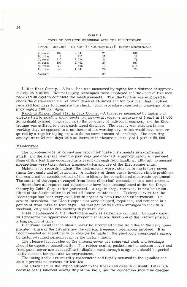
As is evidenced (Table 2) the average cost of operating the Electrotape in making basic control surveys for photogrammetric compilation of maps is approximately $24 per man day. It should be pointed out that this cost is greater than can be ordinarily expected because the instruments have, for the purposes of this research project, been operated to a large extent by professional engineering personnel whose salaries are well above the range usually offered for this type of work.
The cost per measurement is very economical when it is considered one set of measurements could extend control for a distance of 20 to 30 miles over extremely rough and wooded topography. Comparisons between this cost and those incurred by a taping crew covering the same distance are given in the following two examples:
24
TABLE 2
COSTS OF DISTANCE MEASURING WITH THE ELECTROTAPE
Project Man Days Total Cost ( $) Cost/Man Day ( $) Number Measurements
A, rural 107 2,547 23 108 B, urban 8 217 27 21 C, rural 115 2, 734 24 75 D, rural 105 2,462 23 100 E, urban 30 558 19 N.A. F, urban 40 1,047 26 24
Average 24
1-10 in Kerr County. -A base line was measured by taping for a distance of approximately 26. 6 miles. Normal taping techniques were employed and the crew of five men required 30 days to complete the measurements. The Electrotape was employed to check the distances in lieu of other types of closures and for four men thus involved required four days to complete the check. Such procedure resulted in a savings of approximately 100 man days.
Ranch to Market Road 2475 in Jack County. - A traverse measured by taping and closure tied to existing monuments had an overall closure accuracy of 1 part in 11,000. Some doubt existed, however, as to the accuracy of individual courses, and the Electrotape was utilized to check each taped distance. The survey was checked in one working day, as opposed to a minimum of six working days which would have been required by a regular taping crew to do the same amount of checking. The resulting savings were 24 man days with an increase in closure accuracy to 1 part in 50,000.
Maintenance
The out-of-service or down-time record for these instruments is exceptionally small, and the average over the past year and one-half is approximately 4. 7 percent. None of this lost time occurred as a result of rough field handling, although no unusual precautions were taken during transportation and use of the Electrotape units.
Maintenance records indicate the instruments were returned to the factory seven times for repair and adjustments. A majority of these cases involved simple problems that could not be considered out of the oridinary for complicated electronic equipment. The nature of the repairs ranged from loose electrical connections to a bent antenna .
Heretofore all repairs and adjustments have been accomplished at the San Diego factory by Cubic Corporation personnel. A repair shop, however, is now being outfitted at the Austin office to effect all future maintenance. Factory service for the Electrotape has been very excellent in regard to both time and effectiveness. On several occasions, the Electrotape units were shipped, repaired, and returned in a period of from three to four days. As this period was often arranged to include a weekend, only one to two working days were lost.
Field maintenance of the Electrotape units is extremely nominal. Ordinary care will preserve the appearance and proper mechanical functions of the instruments for a long period of time.
Electronic maintenance should never be attempted in the field due to the very complicated nature of the circuits and the critical frequency tolerances involved. It is recommended no adjustments or changes be made in the electronic components except by factory-trained personnel or by the factory itself.
The closure turnbuckles on the antenna cover are somewhat weak and breakage should be expected occasionally. The rubber sealing gaskets on the antenna cover and front panel cover are susceptible to displacement through usage and should be periodically checked for dust and waterproofness.
The tuning knobs are sturdily constructed and tightly secured to the spindles and should present no serious difficulties.
The attachment of the tripod adapter to the fiberglass case is of doubtful strength because of the inherent nonrigidity of the shell, and the connection should be checked
frequently for signs of fatigue cracks or ruptures. The bolts forming connections should be tightened occasionally to prevent the case from shifting on the adapter and thereby dislocatm:g the electronic center.
25
For fullest utilization, the units should require no more care in field transporting and handling than would be ordinarily given an optical surveying instrument. Consequently no special precautions have been taken to protect the instruments from mistreatment other than precautions usually taken with a transit or theodolite.
The square shape and high center of gravity of the instruments create a problem when operating in high to moderate wind velocities. This is not a correctable condition insofar as mechanical modifications are concerned. Prudent care, however, should be exercised in the height of setup, implantation of the tripod shoes, and constant close proximity of the operator when such weather is experienced. Operation in a light rain is possible. The antenna disk is sealed against the case, and water infiltration from that direction is not likely . Excessive exposure of the dials and counter to rain will undoubtedly cause some difficulty, and the employment of a large umbrella is necessary when operation in the rain must continue. At present, insufficient data prevent the drawing of a conclusion as to the accuracy obtained when measurements are made during raining conditions.
The antenna is a rather delicate appendage and is easily bent or otherwise damaged. When such damage occurs, transmitting efficiency may be seriously impaired; consequently the antenna cover should always be attached except when measurements are actually being made.
It has not been necessary to utilize the large wooden cases in ordinary transporting, and their inclusion when the instruments are carried by a walking field crew adds weight that is totally unjustified. They have been reserved for those instances when it is necessary to ship the instruments to a distant destination.
CONCLUSIONS
In conclusion, the following points are offered in summary of the foregoing:
1. The Electrotape has a definite and valuable use in the work of a normal highway survey crew in:
a. Establishing closure stations approximately 2, 000 feet apart thereby insuring ultimate closure of at least second-order for the traverse at the expense and time usually required to make a third- or fourth-order survey by usual onthe-ground surveying methods.
b. Extending control from the end and/ or beginning of a transit and tape survey for closure on a monument in the previously established network of basic control, or in forming the return loop of a closed circuit to prove second-order accuracy.
c. Performing in an efficient and economical manner to allow accomplishment of (a) and (b) preceding.
d. Finding taping errors in completed transit and tape surveys more efficiently than could be accomplished by other ground surveying techniques.
e. Determining distances over topographic areas inaccessible to a taping crew. 2. As a surveying instrument, the Electrotape is capable of:
a. Being effectively operated by inexperienced personnel after a minimal in-struction period.
b. Withstanding normal field handling. c. Requiring very little maintenance. d. Achieving accuracies of second-order or better without resorting to the usual
and expensive second-order surveying techniques. e. Requiring few accessories for efficient operation.