evaluation of weld flaws
TRANSCRIPT
SSC-213
A GUIDE FOR ULTRASONIC TESTING ANDEVALUATION OF WELD FLAWS
This document has been approvedfor public release and sale; its
distribution is unlimited.
SHIP STRUCTURE COMMITTEE
1970

SHIP STRUCTURE COMMITTEE
1970
Dear Sir:
To maintain the high degree of safety and reli-ability in ship fabrication, the Ship Structure Committeehas completed a project that provides an ultrasonic inspec-tion guide that retains the comparable radiographic standardprovided earlier.
The results of this project are contained inthis report.
Sincerely,
W. F.Réa, IIIRear Admiral, U.S. Coast GuardChairman, Ship Structure Committee
MEMBER AGENCIES: ADDRESS CORRESPONDENCE TO:
UNI TED STATES COAST GUARD SECRETARYNAVAL SHIP SYSTEMS COMMAND SHIP ST RUCTURE COMMITTEEMILITARY SEA TRANSPORTATION SERVICE U.S. COAST GUARD HEADQUARTERSMARITIME ADMINISTRATION WASHINGTON. D.C. 20591AMERICAN BUREAU OF SHIPPING

SSC -2 13
Final Report
on
Project SR-188, 'Ultrasonic Test Guide'
to the
Ship Structure Committee
A GUIDE FOR ULTRASONIC TESTING AND EVALUATIONOF WELD FLAWS
by
R. A. Youshaw
U.S. Naval Ordnance Laboratory
under
Department of the NavyNaval Ship Engineering CenterProject No. SF 35422306
Task 02022
This document has been approved for publicrelease and sale, its
distribution is unlimited.
U. S. Coast Guard HeadquartersWashington, D.C.
1970
A B ST RA CT
This document presents procedures and acceptance limitsfor contact ultrasonic inspection of steel butt welds in thethickness range of 1/4 to 2 inches. The acceptance limits de-scribed in the following sections are compatible with those setforth in SSC-177, "Guide for Interpretation of NondestructiveTests of Welds in Ship Hull Structures" for radiographic inspec-tion and should therefore result in satisfactory ship welds.
The SHIP STRUCTURE COMMITTEE is constituted to prosecute a researchprogram to improve the hull structures of ships by an extension of knowledge
pertaining to design, materials and methods of fabrication.
RADM W. F. Rea, III, USCG, ChairmanChief, Office of Merchant Marine Safety
U. S. Coast Guard Headquarters
Capt. W. R. Riblett, USNHead, Ship Engineering DivisionNaval Ship Engineering Center
Capt. T. J. Banvard, USNMaintenance and Repair OfficerMilitary Sealift Command
SHIP STRUCTURE SUBCOMMITTEE
The SHIP STRUCTURE SUBCOMMITTEE acts for the Ship Structure Committeeon technical matters by providing technical coordination for the determinationof goals and objectives of the program, and by evaluating and interpreting the
results in terms of ship structural design, construction and operation.
NAVAL SHIP ENGINEERING CENTER U. S. COAST GUARD
Mr. J. B. O'Brien - Acting Chairman LCDR C. S. Loosmore, USCG - SecretaryMr. J. B. O'Brien - Contract Administrator COR C. R. Thompson, USCG - MemberMr. G. Sorkin - Member [COR J. W. Kime, USCG - Alternate
Mr. H. S. Sayre - Alternate Capt. L. A. Colucciello, USCG - AlternatEMr. I. Fioriti - Alternate
NATIONAL ACADEMY OF SCIENCESMARITIME ADMINISTRATION
Mr. F. Dashnaw - MemberMr. A. Maillar - MemberMr. R. Falls - AlternateMr. W. G. Frederick - Alternate
AMERICAN BUREAU OF SHIPPING
Mr. S. G. Stiansen - MemberMr. F. J. Crum - Member
OFFICE OF NAVAL RESEARCH
Mr. J. M. Crowley - MemberDr. W. G. Rauch - Alternate
NAVAL SKIP RESEARCH & DEVELOPMENT CENTER
Mr. A. B. Stavovy - Alternate
MILITARY SEALIFT COMMAND
Mr. R. R. Askren - MemberLt. J. G. T. E. Koster, USN, - Member
SHIP STRUCTURE COMMITTEE
Mr. E. S. DillonDeputy ChiefOffice of Ship ConstructionMaritime Administration
Mr. C. J. L. Schoefer, Vice PresidentAmerican Bureau of Shipping
Mr. A. R. Lytle, LiaisonMr. R. W. Rumke, LiaisonProf. R. A. Yagle, Liaison
SOCIETY OF NAVAL ARCHITECTS & MARINEENGINEERS
Mr. T. M. Buermann, Liaison
AMERICAN IRON AND STEEL INSTITUTE
Mr. J. R. LeCron, Liaison
BRITISH NAVY STAFF
Dr. V. Flint, LiaisonCDR P. H. H. Ablett, RCNC, Liaison
WELDING RESEARCH COUNCIL
Mr. K. H. Koopan, LiaisonMr. C. Larson, Liaison
111

CONTENTS
SCOPE i
TEST METHOD i
PERSONNEL QUALIFICATION 3
CALIBRATION STANDARDS 4
INSTRUMENT CALIBRATION 4
WELD INSPECTION 5
DISCONTINUITY LENGTH DETERMINATIONS 5
DISCONTINUITY EVALUATION 8
RECORD OF INSPECTION 8
GLOSSARY OF TERMS 11
iv
SCOPE
This document presents procedures and acceptance limitsfor contact ultrasonic inspection of steel butt welds in thethickness range of 1/4 to 2 inches. The acceptance limitsdescribed in the following sections are compatible withthose set forth in SSC-177, "Guide for Interpretation ofNondestructive Tests of Welds in Ship Hull Structures" forradiographic inspection and should therefore result in satis-factory ship welds. Occasions may arise where radiographicinspection could provide additional information.
TEST METHOD
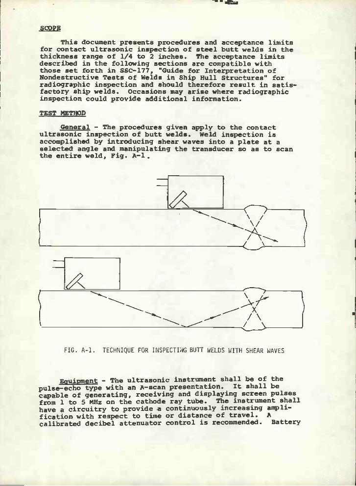
General - The procedures given apply to the contactultrasonic inspection of butt welds. Weld inspection isaccomplished by introducing shear waves into a plate at aselected angle and manipulating the transducer so as to scanthe entire weld, Fig. A-l.
X/\/
FIG. A-1. TECHNIQUE FOR INSPECTING BUTT WELUS WITH SHEAR WAVES
Eauipment - The ultrasonic instrument shall be of thepulse-echo type with an A-scan presentation. It shall becapable of generating, receiving and displaying screen pulsesfrom 1 to 5 MHz on the cathode ray tube. The instrument shallhave a circuitry to provide a continuously increasing ampli-fication with respect to time or distance of travel. Acalibrated decibel attenuator control is recommended. Battery

PLASTIC DISC
NOTE: ALL DIMENSIONS IN MILLIMETERSi INCH =25.4MM
-2-
powered equipment must contain an alarm to signal batterydepletion prior to instrument shut-off due to battery exhaustion.
Transducers - The maximum dimension (manufacturers'specifications) of the transducer active element shall notexceed one inch. A ratio of 2:1 width to height of the activeelement is recommended. A nominal test frequency of 2.25 MHzis recommended.
Selection of Probes - The primary consideration forselecting a probe shall be the thickness of the plate. Thefollowing shear wave angles are recommended:
70° for plate thicknesses 1/4" to 1/2"
60° or 70° for plate thicknesses 1/2" to l-1/2"
45° or 60° for plate thicknesses 1-1/2" to 2-1/2".
The transducer angle should be checked periodically with theInternational Institute of Welding Test Block, Fig. A-2.
Couplant - A liquid such as glycerin diluted with alcoholor water and to which a wetting agent has been added isrecommended for acoustic coupling between the transducer andthe plate. Most oils are acceptable. For overhead work andfor places of difficult access certain types of grease may
91
FIG. A-2. INTERNATIONAL INSTITUTE OF WELDING TEST BLOCK FOR ULTRASONIC CALIBRATION
25 23
+-r
300200

-3-
prove useful. Any couplant should be removed upon completionof the inspection.
Surface Preparation - The average plate as received fromthe mill has a surface that is smooth enough for ultrasonicinspection. Plate with loose scale, flaked paint, excess rust,or pitting will require grinding. After welding, the surfaceof the base metal where the probe is to be manipulated shouldbe cleaned of weld splatter. If surface irregularities on theweld bead interfere with the ultrasonic test or cause diffi-culties in interpretation then the weld bead should be groundreasonably smooth.
Base Metal Inspection - Although the presence of laminationsin the base metal may not be a basis for rejection, thesereflectors may mask a part of the weld from the ultrasonicbeam, Fig. À-3, or cause the operator to incorrectly locatea discontinuity, Fig. Â-4. Laminations can be detectedultrasonically with a straight beam (longitudinal waves).When laminations are encountered, the inspection should bemade from the other side of the weld.
PERSONNEL QUALIFICATION
Supplement C, Ultrasonic Testing Method, TC-1A RecommendedPractice, American Society for Nondestructive Testing, shall apply.Ultrasonic testing may be carried out by a Level II operator orby a Level I operator under the direct supervision of a Level IIoperator.
- -___\ /
/
LAMINATION
ACTUAL DEFECT LOCATION-. \/
LAMINATIOIJ 'A.4INFERRED DEFECT LOCATION
J \/ \/ \/
FIG. A-3. MASKING EFFECT OF A BASE METAL LAMINATION
FIG. A-4. POSITION ERRORS INTRODUCED BY BASE METAL LAMINATION

CALIBRATION STANDARDS
A test block shall be prepared from material experimentallydetermined to be defect free and which is acoustically similarto the work material. This block should b l-1/4" thick witha series of 1/16" diameter drilled holes spaced to provide pathlengths equivalent to the longest and shortest path lengths tobe used in the weld inspection. Intermediate distances shouldalso be provided. The scanning surfaces should be approximately250 RMS, prepared by the grinding method with the direction ofgrind parallel to the long dimension of the test block. Figure 5illustrates an acceptable design.
SURFACE FINISH ON THE SCANNING SURFACES TO BEAPPROXIMATELY 250 RMS PREPARED BY GRINDING METHODWITH THE DIRECTION OF GRIND PARALLEL TO THE LONGDIMENSIONS OF THE BLOCK.
-4-
rl il Il jr IlII II II II IIII II Ii I IIII II II II IIII II J j JI II
IIIIIIII
-i pJui 2 + 2 .fi 2 .fui 2 + «f.' -..J
SCANNING SURFACE
1/16D
2_1I/4 2-1/2 2-3/4°1_1/2 I-3/4"
SCANNING SURFACE
FIG. A-5. TYPICAL REFERENCE CALIBRATION STANDARD
INSTRUMENT CALIBRATION
Two levels of signal amplitude are defined in this Guide -ARL (Amplitude Reject Level) and DRL (Disregard Level). Thesetwo levels are established as follows:
The delay controls are used to position the initial pulse
at the left of the viewing screen at'°'°a location marked zero
on a reticule or screen scale. The instrument range controlscan then be adjusted to display signals from the referencecalibration drilled holes for the distances to be considered.
The distance amplitude correction controls are to beadjusted to compensate for signal loss due to distance oftravel, i.e., the height of signals from all the reference
T1-1/4±
T
F12
H

-5-
drilled holes should be made equal.
When a decibel attenuator is available, the instrumentgain control is to be adjusted to set the equalized signalsfrom the reference reflectors at 40% of full screen height,Fig. Â-6. The gain is then increased by 6 decibels. Jt thissetting, the ARL is 6 decibels above the 40% line and the DRL(screen height below which indications are to be disregarded)shall be the 40% line, Fig. A-6.
When a decibel attenuator is not available, the instrumentgain control is to be adjusted to set the equalized signalsfrom the reference reflectors at 80% of full screen height,Fig. A-7. For this setting the 40% line shall be the DRL andthe 80% line shall be the ARL, Fig. A-7.
In both of the above cases the calibration should bechecked frequently.
WELD INSPECTION
Longitudinal defects are found by directing the sound beamnormal to the length of the weld and moving the transducer backand forth, Fig. A-8, to scan the entire weld. Simultaneously,the transducer is oscillated through a small angle. The backand forth motions should be repeated at intervals which do notexceed 80% of the width of the transducer as the probe is movedalong the weld.
Transverse defects are detected as follows:
For welds ground smooth the transducer isplaced on top of the weld and moved along its length,Fig. A-9.
For welds not ground smooth the transduceris placed alongside and not quite parallel to theweld and moved along the length, Fig. A-10.
The entire weld and heat affected zone should be scanned.The weld should be inspected from both sides of one surface.
QISCONT INtJITY LENGTH DETERMINATI0NS
When discontinuities are detected, the sound beam shouldbe directed so as to maximize the signal amplitude. Thetransducer is then moved parallel to the discontinuity andaway from the position of maximum signal amplitude. Theextremity of the discontinuity is defined as the point atwhich the signal amplitude drops to one-half of the peakvalue. This point is marked using the center line of the wedgeas an index. In a similar manner, the other extremity is foundand the distance between marks is defined as the length of thediscontinuity. The minimum recordable length of a discontinuityshall be 1/8".

-6-
APPROXIMATELY 80%--
6 db
80
70
60
50
40
30
20
10
o
FIG. A-6. TYPICAL VIEWING SCREEN CALIBRATIONFOR INSTRUMENTS WITH DECIBEL ATTENUATION CONTROLS
100
go
80
70
60
50
40
30
20
10
o
FIG. A-7. TYPICAL VIEWING SCRETN CALIBRATIONFOR INSTRUMENTS WITHOUT DECIBEL ATTENUATION CONTROLS
NOTE: CALIBRATION IS PERFORMED WITH THE REFLECTION OBTAINED FROM THE WALL OF A1/16" DRILLED HOLE USING DISTANCE-A1PLITUDE CORRECTIONS.
ARL
D RL
ARL
DRL

?PTh
r.r.r.-
r-
.- .-..-.
FIG. A-8. TECHNIQUE FOR INSPECTING BUTT WELDS WITH SHEAR WAVES
FIG. A-9. SUPPLEMENTARY TECHNIQUE FORINSPECTING BUTT WELDS WHEN THE WELD BEAD
IS GROUND FLUSH
-7-
TRANSDUCER SONICPATH
(a)
NOTE: USE SIMILAR SCAN PATH ON OPPOSITE SIDE OF WELD OHSAMI SURFACE.
FIG. A-10. SUPPLEMENTARY TECHNIQUE FORINSPECTING BUTT WELDS WHEN THE WELD BEAD IS
NOT GROUND FLUSH

DISoeNTINUITY EVALUATION
-8 -
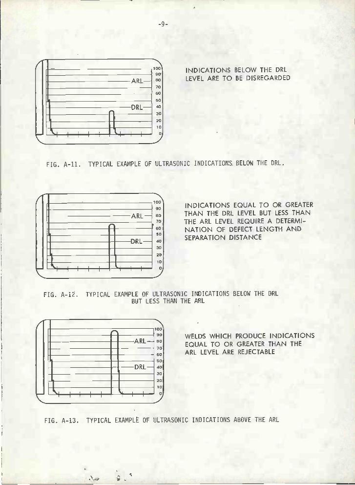
Discontinuities which do not produce signal amplitudesequal to or greater than the DRL, Fig. A-11, shall bedisregarded.
Discontinuities which cause signal amplitudes equal toor greater than the DRL but less than the ARL, Fig. A-12,require a length determination and are evaluated as follows:
Defects with length greater than T where T isthe thickness of the plate are unacceptable.
For multiple indications, where L is the lengthof the larger discontinuity, if the separationdistance is less than 6L then the sum of theadjacent lengths shall not exceed T. If theseparation distance is more than 6L then thecumulative length in any 6" length of weld shallnot exceed the plate thickness.
ny discontinuity which produces signal amplitudes in excessof the ARL, Fig. A-13, is unacceptable.
When base metals of different thicknesses are weldedtogether the thickness of the thinner member shall be used indeterminations of acceptable limits of discontinuities.
With the ultrasonic instrument calibrated in accordancewith the procedures set forth in this Guide, usual signalamplitudes for specific type weld defects in relation to theARL and DRL are illustrated in Fig. A-14.
When rejectable conditions are encountered, radiographymay be useful in determining the nature and extent of thediscontinuity.
RECORD OF INSPECTION
The record of each weld inspection should include:
Operator's identityDateInstrument identityTransducer type, size, frequency and angleIdentification of test objectLocation of the weldType of materialThickness of base plateType of joint and configurationCondition of the weld bead
il. CouplantFlaw dataInspection coverage, including reference points.
ARL-
e
D RL
IF
FIG. A-11. TYPICAL EXAMPLE OF ULTRASONIC INDICATIONS BELOW THE DRL.
i?ARL- 80
706050
DRL- 4030
20
10
o,
INDICATIONS BELOW THE DRLLEVEL ARE TO BE DISREGARDED
INDICATIONS EQUAL TO OR GREATERTHAN THE DRL LEVEL BUT LESS THANTHE ARL LEVEL REQUIRE A DETERMI-NATION OF DEFECT LENGTH ANDSEPARATION DISTANCE
FIG. A-12. TYPICAL EXAMPLE OF ULTRASONIC INDICATIONS BELOW THE DRLBUT LESS THAN THE ARL
WELDS WHICH PRODUCE INDICATIONSEQUAL TO OR GREATER THAN THEARL LEVEL ARE REJECTABLE
FIG. A-13. TYPICAL EXAMPLE OF ULTRASONIC INDICATIONS ABOVE THE ARL
I loo90
ARL- 80706050
DRL- 4°30
2O

-10-
WITH THE ULTRASONIC INSTRUMENT CALIBRATED IN ACCORDANCE WITHTHE PROCEDURES SET FORTH IN THIS GUIDE, WELD DEFECTS OF THETYPES LISTED WILL USUALLY PRODUCE SIGNAL AMPLITUDES IN RELATIONTO THE ARL AND DRL LEVELS AS SHOWN:
ARL
DRL
FIG. A-14. TYPICAL ULTRASONIC SIGNAL AMPLITUDES PRODUCED BY VARIOUS DEFECTS
CRACKSPENETRATION
CRACK LIKE SLAGPIPING- INCOMPLETE
LACK OF FUSION LINEAR POROSITY
SEVERE POROSITY-MULTIPLE SLAG INCLUSIONS
ROUND EDGE SLAG- CLUSTERED POROSITY
MILD SCATTERED POROSITY
loo
90
80-70
60
50
40
30
20
lo
o

A-Scan
Megahertz(MHZ)
-11-
GLOSSARY OF TERMS
- A method of data presentation on a cathode raytube utilizing a horizontal base line whichindicates elapsed time when reading from leftto right. A vertical deflection from the baseline indicates reflected signal amplitudes.
Acoustically The same type of material as that to beSimilar - inspected, or another material which has been
experimentally proven to have acoustic velocitywithin ±3% and an attenuation for shear waves atthe frequency to be used within ±0.25 dB/inch ofthe material to be inspected.
ActiveElement - The piezo-electrical material in the ultrasonic
probe.
ARL (AmplitudeReject Level - The horizontal level on the cathode ray tube
established by calibration. After calibrationthe ARL is 80% full screen height or 6 dB abovethe 40% line if a decibel attenuator is available.
Decibel - A logarithmic function of the ratio of twovalues. In ultrasonics the two values are thesignal amplitude and a reference amplitude.
DecibelAttenuator - A gain control calibrated in decibels.
DelayControls - An electronic means of horizontally shifting the
pattern obtained on the cathode ray tube.
DRL (DisregardLevel) - The horizontal level on the cathode ray tube
established by calibration. After calibrationthe DRL is 40% of full screen height.
Frequency - The number of cycles in a unit of time. Inultrasonics the frequency is usually expressedin Megahertz or MHz (million cycles per second).
Longitud mlWaves - A wave form in which the particle motion is
essentially in the same direction as the wavepropagation.
- A million cycles per second.
Pulse Echo - The sending of sound into a material in theform of spaced pulses and recording the lengthof time necessary for each pulse to travel

-12-
through the medium and return to the source ofenergy.
MS (RootMean Square) - A type of average used in describing surface
roughness.
ResultingAnqie - The angle formed between the ultrasonic beani
as it enters a medium of different characteris-tics than the one from which it came and a linedrawn perpendicular to the interface betweenthe two media.
ScanningSurface - The surface of the base metal where the ultra-
sonic probe is manipulated.
Shear Wave - A wave form in which the particle motion isperpendicular to the direction of wave travel.
Straighteam - An ultrasonic technique which does not involve
an angle. The wave form is longitudinal.
Transducer - A device for converting energy of one type intoanother. An ultrasonic transducer convertsenergy from electrical to mechanical andvice versa.

I IN (LASS IF_EDSecurity Classification
D D FORMJAN 64 UNCLASSIFIEDSecurity C1assificaon
DOCUMENT CONTROL DATA R&D(Secur, ty class, f,cation of t, tie, body of abstract and indexing annotation must be entered when the overa!! report i classified)
i ORIGINATIN G ACTI'II'Th' (Corporate author)
U. S. NAVAL ORDNANCE LABORATORYWhite Oak, F'laryland
2e, RCPORT SECURITY C LASSIFICATION
Unclassified2h GROUP
3 REPORT TITLE
A Guide For Ultrasonic Testing and Evaluation of Weld Flaws
4. DESCRIPTIVE NOTES (Type of report arid inclusive dates)
Final Report--5. AUTHOR(S) (Last name, first name, initial)
R. A. Youshaw
6. REPORT DATEAugust, 1970
7e. TOTAL NO. OF PAGES
12
7h. NO OF REFS
0
6a. CONTR4CTORGRANTNO.
b. PROJECT NO SF 35422306TASK: 02022
s.
d.
Sa, ORIGINATORSREPORTNLJMBER(S)
NOLTR 70-85
Sb. OrNER REPORT NO(S) (Any other numbers that maybe assignedthis report)
SSC-21310. A V A IL ABILITY/LIMITATION NOTICES
DISTRIBUTION OF THIS DOCUMENT, SSC-213, IS UNLIMITED.
il. SUPPLEMENTARY NOTES 12. SPONSORING MILITARY ACTIVITY
Naval Ship Engineering Center
13. ABSTRACT
Tris document presents procedures and acceptance limits for contact
ultrasonic inspection of steel uutt welds in the thickness range of 1/4 to2 inches. The acceptance limits described in the following sections arecompatible with those set forth in SSC-177, "Guide for Interpretation ofNondestructive Tests of Welds in Ship Hull Structures" for radiographicinspection and should therefore result in statisfactory ship welds.

UNCLASSIFLLDSecurity ulassirication
1, ORIGINATING ACTIVITY: Enter the name and addressof the contractor, subcontractor, grantee, Department of De-fense activity or other organization (corporate author) issuingthe report.2a. REPORT SECUTY CLASSIFICATtON: Enter the Over-all security classification of the report. Indicate whether"Restricted Data' is included. Marking is to be in accord-ance with appropriate security regulations.2h. GROUP: Automatic downgrading is specified in DoD Di-rective 5200. 10 and Armed Forces Industrial Manual. Enterthe group number. Also, when applicable, show that optionalmarkings have been used for Group 3 and Group 4 as author-ized.
REPORT TITLE: Enter the complete report title in allcapital letters. Titles in all cases should be unclassified.If a meaningful title cannot be selected without classifica-tion, show title classification in all capitals in parenthesisimmediately foil owing the titi e.
DESCRIPTIVE NOTES: If appropriate, enter the type ofreport, e.g., interim, progress, summary, annual, or final.Give the inclusive dates when a specific reporting period iscovered.
AUTHOR(S): Enter the name(s) of author(s) as shown onor in the report. Entei last name, first name, middle initial.If military, show rank and branch of service. The name ofthe principal author is an absolute minimum requirement.
REPORT DATE: Enter the date of the report as day,month, year; or month year. If more than one date appearson the report, use date of publication.
TOTAL NUMBER OF PAGES: The total page countshould follow normal pagination procedures, i.e., enter thenumber of pages containing information.
NUMBER OF REFERENCEK Enter the total number ofreferences cited in the report.8a. CONTRACT OR GRANT NUMBER: If appropriate, enterthe applicable number of the contract or grant under whichthe report was written.8h, Sc, & 8d. PROJECT NUMBER: Enter the appropriatemilitary department identification, such as project number,subproject number, system numbers, task number, etc.Qa. ORIGINATOR'S REPORT NUMBER(S): Enter the offi-cial report number by which the document will be identifiedand controlled by the originating activity. This number mustbe unique to this report.9h. OTHER REPORT NUMBER(S): If the report has beenassigned any other report numbers (either by the originatoror by the sponsor), also enter this number(s).10. AVAtLABILITY,'LIMITATION NOTICES: Enter any lim-itations on further dissemination of the report, other than those
INSTRUCTIONS
imposed by security classification, using standard statementssuch as:
"Qualified requesters may obtain copies of thisreport from DDC.""Foreign announcement and dissemination of thisreport by DDC is not authorized.""U. S. Government agencies may obtain copies ofthis report directly from DOC. Other qualified DDCusers shall request through
"U. S. military agencies may obtain copies of thisreport directly from DDC. Other qualified usersshall request through
"All distribution of this report is controlled. Qual-ified DDC users shall request through
If the report has been furnished to the Office of TechnicalServices, Department of Commerce, for sale to the public, indi-cate this fact and enter the price, if known.
SUPPLEMENTARY NOTES: Use for additional explana-tory notes.
SPONSORING MILITARY ACTIVITY: Enter the name ofthe departmental project office or laboratory sponsoring (pay-ing for) the research and development. Include address.
ABSTRACT: Enter an abstract giving a brief and factualsummary of the document indicative of the report, even thoughit may also appear elsewhere in the body of the technical re-port.. If additional space is required, a continuation sheet shallbe attached.
It is highly desirable that the abstract of classified reportsbe unclassified. Each paragraph of the abstract shall end withan indication of the military security classification of the in-formation in the paragraph, represented as (rs). (S), (C). or (U)
There is no limitation on the length of the abstract. How-ever, the suggested length is from 150 to 225 words.
KEY WORDS: Key words are technically meaningful termsor short phrases that characterize a report and may be used asindex entries for cataloging the report. Key words must beselected so that no security classification is required. Identi-fiers, such as equipment model designation, trade name, militaryproject code name, geographic location, may be used as keywords but will be followed by an indication of technical con-text. The assignment of links, roles, and weights is optional.
UNiCI ASST FlEDSecurity Classification
14 LINK A LINK B LINK CKEY WORDS
RO L E WV RO L E wr ROLE WT