evolution of real time computer systems for test benches
TRANSCRIPT

Evolution of
real time computer systems
for test benchesA computer system for a test bench � spoilt for choice
Stuchlik, Wolfgang∗
German Aerospace Center (DLR)Institute of Space Propulsion74239 Hardthausen, Germany
March 18, 2016
1 Abstract
This paper covers the development of computersystems during the course of the last 25 years forthe Ariane project ESA test benches P5, P4.1 andP4.2. On these test benches the DLR-teams aretesting and qualifying the rocket engines "Vul-cain2", "Vinci" and "Aestus". Twenty-�ve yearsago the criteria for speci�cation and procurementfor test bench computer systems was very di�erentfrom today.Mostly the systems were custom made and very of-ten the component interfaces had to be developedspeci�cally for the site. Systems o�ering high reli-ability, that would run 24 hours a day and on 365days a year were very much the exception.The preventive and reactive maintenance were notonly cost intensive but also very complicated andlabour-intensive. The provision of spare parts wasalso a critical point. The necessity of ensuring thatparts were available in good time was also an ex-pensive option.The hardware was sometimes only of limited usesince even the production batch numbers of com-ponents had to be taken into account. The situ-ation has changed dramatically during the courseof the last ten years.
• The processing power of CPUs has risen dueto the enormous increase in clock rates.
• Multiuser and multitasking have become thestandard modes of computer operation.
• The costs associated with processors havefallen due to the e�ects of mass production.
• Commercial operating systems have no prob-lem with the management of computer mem-ories measured in GBytes.
• The probability of failure associated with elec-tronic components is much lower.
The procurement lead-time for components hasbeen reduced. An Internet connection allows apermanent connection between customer and sup-plier. The thermal e�ects on the system havebeen reduced dramatically due to the reductionin the amount of internally generated heat withinthe components. The operation of a system nolonger requires specialist knowledge since the manmachine interfaces have been designed to be as in-tuitive as possible. The operator is guided throughthe steps required to perform a particular opera-tion.New criteria, but with weaknesses emerging, forexample:
• Hardware aging � the replacement of moni-tors, graphic cards, hard disks and memorycards needs to be carried out regularly, duesupport no longer being available.
• Support for PC operating systems is oftenavailable only for a limited duration. Operat-ing system updates and software migrationsafter an operating system change bring with
1
them additional costs and operational down-time.
• The access to systems allowing maintenance,to be performed remotely, must be im-plemented and possibly guaranteed. Thismethod allows workload to be reduced on siteon behalf of the maintenance company but itdoes mean, that customer sta� must be avail-able to assist when necessary.
To de�ne only one type of computer-system (in-cluding the measurement- and command equip-ment), from one supplier, with one maintenancecontract and one spare part stock for all testbenches of one test area would be the ideal so-lution. Each test bench has a purpose and youneed a tailored system for this � not only from thetechnical aspect.
2 Three generations of Computer
Systems
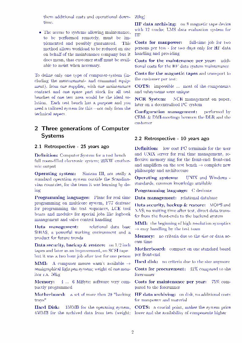
2.1 Retrospective - 25 years ago
De�nition: Computer System for a test bench =full room-�lled electronic system; 25KW exother-mic output
Operating system: Sintran III, not really astandard operation system outside the Scandina-vian countries, for the team it was learning by do-ing
Programming languages: Planc for real timeprogramming on multicore system, F77 derivatefor programming the test sequences, LCE toolboxes and modules for special jobs like logbookmanagement and valve control handling
Data management: relational data baseSIBAS, a powerful working environment and aproduct for future trends
Data security, backup & restore: on 1/2 inchtapes and later as an improvement, on SCSI tape -but it was a two hour job after test for one person
MMI: A computer mouse wasn't available →semigraphical lightpen system; weight of one mon-itor r.a. 50kg
Memory: 4 ... 6 MByte; software very com-pactly programmed
Motherboard: a set of more then 20 "backingtrays"
Hard Disk: 150MB for the operating system,450MB for the archived data from test (weight:
20kg)
HF data archiving: on 8 magnetic tape devicewith 12 tracks; LMS data evaluation system forHF
Costs for manpower: full-time job for twopersons per test - for two days only for HF datahandling and providing
Costs for the maintenance per year: addi-tional costs for the HF data system maintenance
Costs for the magnetic tapes and transport tothe customer per test:
COTS: impossible ... most of the componentsand subsystems were unique
NCR System: NCR management on paper,later on a decentralised PC system
Con�guration management: performed byCEM- & DMI-meetings between the DLR and thecustomer
2.2 Retrospective - 10 years ago
De�nition: low cost PC terminals for the userand UNIX server for real time management, re-�ective memory ring for the front-end; front-endand ampli�ers on the test bench → complete newphilosophy and architecture
Operating systems: UNIX and Windows -standards, common knowledge available
Programming language: C derivate
Data management: relational database
Data security, backup & restore: MOPS andNAS; no waiting time after test, direct data trans-fer from the front-ends to the backend system
MMI: the beginning of high resolution synoptics→ easy handling by the test team
Memory: no criteria due to the size or data ac-cess time
Motherboard: compact on one standard boardper front-end
Hard disk: no criteria due to the size anymore
Costs for procurement: 41% compared to theforerunner
Costs for maintenance per year: 75% com-pared to the forerunner
HF data archiving: on disk, no additional costsfor manpower and material
COTS: a crucial point, makes the system pricelower and the availability of components higher
2

NCR system: database, contact with the sup-plier by eMail, maintenance and checks by remoteaccess possible
Con�guration management: by DLR withoutthe customer
2.3 Real time systems do not need ...
• extreme high clock rate for CPU → see PCcommercial presentations ... higher clock fre-quency because better for ... what? (in factfor graphical applications, games)
• SIO, PIO and DMA hardware modules→ thereal time systems need bu�ers for the archiveddata, fast link (optic �ber) between front-endand back-end system
• high resolution graphic, more than 256colours are not necessary (for levels of gray,the limit for our eyes is 1024) → a commer-cial gimmick only
2.4 The best location for the front-ends
There are two possibilities for locating the mea-surement data acquisition, conditioning and digi-talisation.
The situation on the P5 test bench:
The front-end is 500m away from the test bench.We have to transmit signals in the range between1mV and 20V and (4-20)mA for industrial trans-mitter.
Advantages:
• Good handling and working in the time of testpreparation and NCR treatments.
• During the test (chill down phases) free ac-cess to the ampli�ers in case of doubts on themeasured signal by the test leader (chill downcriteria, unexpected pressure in a pipe).
• Quick status check of the ampli�er conditions(without MCC).
• Quick status check of the sensor signal qualityor cable condition (short cut/broken).
• synchronism between the LF- and HF data isgiven
Disadvantages:
• Long cabling � high costs for material, cablechute and installation.
• A big challenge for an undisturbed signaltransmission.
• The exact grounding of two systems with adistance of 500m is complicate.
The situation on the test benches P4.1 and P4.2(including the steam generator):
The distance between the object in the test celland the front-end is r.a. 30m.
Advantages:
• short length of cabling, uncritical signal trans-mission � lower costs for mechanical supportsand cable routing
• no serious problems with grounding, the con-nection to the ampli�er is in the same facility
• digitalized data are stored in the front-end; af-ter the archiving the front-end sends the datato the back end system by an Ethernet link
Disadvantages:
• From the point in time when the test leaderstarts the chill down of the test bench we donot have an access to the front-end room.
• In case of an exchange of ampli�er boards theMCC must be stopped. After the EG theMCC should remain untouched for the test.
3

Conclusion:
• Both solutions are acceptable from our expe-rience.
• If the distance - between test bench and testcontrol/MCC room - is greater than 500m,the front-ends should be integrated on the testbench (it means the ampli�ers for the mea-sured signals must be installed in the samebuilding), because the synchronism betweenthe LF-and HF-data could be critical.
2.5 The current MCC systems on the P5test bench
De�nition: compact system; for P5 � in sum-mary: 5 servers, 7 front-ends and switches fordata tra�c and log messages piping. For a remotemaintenance a KVM terminal is available.
Operating system: LINUX on the data mi-dlevel system, Windows 7 for the user terminals,on the front-ends RTX
Programming languages: ST-language withfunctional block diagrams
Data management: by a relational data base
Data security, backup & restore: archiveddata available on the main and redundant server,outsourcing of archived data to a NAS, data re-store from the NAS possible
MMI: Labview product
Memory: GByte - unlimited
Motherboard: per front-end a compact CPUboard → for 2016 an upgrade is scheduled, a�Quad-Core-Processors� for RMS calculations inreal time is to be installed
Hard Disk: this is not a criteria anymore
Costs for the procurement: 17% (in relationto the �rst MCC)
Costs for maintenance per year: 154% (inrelation to �rst MCC)
HF data archiving: on two front-ends for 96channels with the limit of 5 MSamples/s
COTS: the components and subsystems areavailable from stock, but the delivery time by thesupplier must be respected
NCR System: JIRA software, remote access tothe system on demand for the error analysis, trac-ing of the most important task
Con�guration management: if test benchesget the same setup as P5, a common con�gurationmanagement will be recommended
3 Evolution of costs for
investments and maintenance
In steps of years we invested into the computersystems for our test benches.
For the computer systems - for the last twotest benches in Lampoldshausen - more compa-nies submitted an o�er, a better competition (win-win philosophy) was possible. The customer had achoice. We do not need a good deal, we are lookingforward to cooperating successfully with suppliersduring the course of the next years.
conclusion:
• decreasing costs for investment
The reasons for this trend are:
- Availability of hight quality COTS computerhardware.
- The customer-tailor-made software solu-tions, are based on software standards (e.g.Labview, RTX, ARECA). The suppliers jobis the adaptation of the software to the cus-tomers requests.
- During system acceptance, it's not neces-sary to check the complete software body -only the relevant requested parts must be pre-sented and tested.
- The new task for the supplier is the em-bedding of the new system into an alreadyworking infrastructure - adaptation is thekey word.
• according to operational experience we canpoint out the increasing importance of main-tenance
The reasons for this trend are:
- higher quality is requested; we are ISO9001
4

certi�cated and this status requests a profes-sional quality assurance (and more paper)
- more engineering from the supplier ex-pected (improvements, studies regarding ob-solescence)
- shorter reaction times regarding on-line sup-port, spare part provision and on-site inter-ventions
- In case of serious problems, the maintenanceteam must be active onsite. The tools, themethods and the technological knowledge isentirely di�erent to that of 25 years ago. Thehardware is more compact and the software ismore complex.
The costs associated with computer hardware isdecreasing at an ever increasing rate. From thediagram above you can see the trend for costs ofusual in trade storage media.
Computer system on the P5 - designed and builtbetween 1985 and 1989 - Norsk Data, data baseoriented data management and real time compli-ant. The system consist of the data preparationpart, the data acquisition computer, the process
interface (data bu�er system for acquired mea-sured low frequency data and digital events) andthe multicore real time computer for the perfor-mance of the tests on the test bench.
The front-end system for LF data archiving,command sending with a precision of 1ms, eventreceiving and control of 12 regulation valves.
The HF data archived was performed by 8EMI/Thorn magnetic tape devices, with 12 tracksand a bandwidth of 20 kHz. The time synchro-nization between the Norsk Data Computer Sys-tem and the archiving of data on the tapes wasimplemented by the IRIG-B code with a precisionof 1ms.
5

The next generation, after 19 years, the NorskData System was replaced. The data and the con-�guration servers were designed for redundancy onthe P5.
New components for a new generation of elec-tronics: re�ective memory ring, �ber optic inter-faces and cabling. The data tra�c will be managedby intelligent switches.
The front-end of the new system consists of 7racks - the HF data acquisition for 96 channels isalready included.
4 Criteria for a new MCC system
4.1 The purpose of a MCC system
• synchronized archiving of LF- and HF-data
• calculation of RMS values for majority logicsand monitorings
• synchronized archiving of commands andfeedback signals, synchronous to the archivedLF/HF data
• commanding of valves and relays based on a�x time regime
• all instructions should be sent from the sys-tem by a sequence (real time task) on a �xtime regime
• all instructions should be sent interactivelyfrom terminals by an operator test team
• a logbook management for events and mes-sages from the system and the sequences
• control of regulation valves
• interactive communication on terminals be-tween the test team and the processes
• display of the measured parameters and thesystem states
• provision of the archived data
• data management - based on a database
• version management for a traceable work�ow
4.2 Real Time functions
• a unique and de�ned time base (Time CodeGenerator), count down and universal timemanagement
• calculation of �ctive parameters, de�nition ofcalculation time and real time task priorities
• handling of majority logics
• monitoring of assorted digital and analogueparameters
• loop management, cycle time de�nition
6

4.3 Archiving
• de�nition of the maximal test duration
• de�nition of archive plans and rates
• de�nition of the number of analogue parame-ters
• de�nition of the number of �ctive parameters
• archiving of system and process logs and mes-sages from sequences and operators
4.4 I/O channels
All channels between the test bench and the front-end - if not situated in one building - must begalvanically separated.
• number of analogue input channels LF; volt-age signal
• number of analogue input channels LF; cur-rent signal (industrial transmitter technology- �xed measurement ranges)
• number of pulse channels (e.g. count functionfrom �ow meters and rotation modules)
• number of analogue input channels HF; volt-age signal
• number of analogue output signals; voltagesignal
• number of analogue output signals; currentsignal (broken wire check)
• number of digital input channels; the EX zoneprotection must be respected
• number of digital output channels; the EXzone protection must be respected
4.5 Data management
4.5.1 Data evaluation
• plot function on the operators terminals foran assorted group of measured channels underthe real time condition
• quick look function for an initial data evalua-tion → main focus: data format de�nition
• scienti�c data evaluation - main focus: dataformat de�nition/adaptation, use of existingsystems
• transfer of the test data to the customer
4.5.2 Data integrity
• De�nition of safety measures for data keepingin the worst case.
• Creation of a data backup system, with full,di�erential and incremental backup features.
• Creation of a data restore system (logical andphysical).
• RAID con�guration of disks
4.6 Watchdog system
The watchdog function monitors the MCC system,but we have to arm the watchdog �rst. Only if theMCC has the command over the test bench can awatchdog signal be generated.
We have to demonstrate that in any case the testbench and the test is under control.
In fact the watchdog is a complex boolean logic,inside the real time treatment front-end system.It's a combination of di�erent healthy-, heartbeat-and be-ready signals.
In the case of the signal being lost between thehealthy MCC and the safety shut down systema watchdog event occurs, this causes the safetyprocedures to be performed.
Electrically, the28V DC re-quired for theMCC commandchannels is dis-connected by aswitch conduc-tor. The 28V isthen handled bythe safety shutdown system.
The watchdog monitors the state of the hard-ware and software critical to the performance ofa test on the test bench. Examples of critical el-ements include the MCC, software tasks, powersupplies for command and feedback signals. If oneof the critical elements causes the watchdog totrigger, the control of the test bench is switchedautomatically to the safety shut down system.If the watchdog has been armed the safety shutdown system continuously monitors the state ofthe MCC watchdog signal.
The safety shut down system stops the running
7

test in any phase immediately by stopping the en-gine (propellant and oxidation �ows). In the fol-lowing steps the safety system shuts down the en-gine and test bench ensuring a safe status (purgedpipes, nominal working condition in the test andthe other test bench �oors).
4.7 Interfaces to other systems
4.7.1 Manual switching panel
A manual switching panel is the operators work-ing tool number one if the MCC is engaged withother tasks.
During the course of test preparation (data basemodi�cation, sequence programming) the MCC isnot available all of the time, but a lot of jobs arenecessary (tightness checks, tank �lling, functionalchecks on subsystems) on the test bench and onthe engine.
For these performing jobs a manual switch panelis the best solution. It is strongly recommended,that only one system - the MCC or the manualswitch panel - is able to send a command to thetest bench, never both at the same time.
The voltage for sending the commands must beswitched over from one system to the other e.g.by the test leader. This switch-over-logic has tobe installed on the MCC.
4.7.2 Time Code Generator
Each computer system has a system time pro-cess/server. The process is not synchronized bya central time generator. It's the local universaltime and can be set by the computer administra-tor.
For our work on the test bench we not only needuniversal time, we also need the count down timetime. All time depended systems need the sametime and the time must have a central time refer-ence (DCF signal or GPS). That's the reason whywe need a time code generator. It could be an inthe MCC integrated system (scheduled for 2016 onP5) or an external device with an interface to theMCC as now on the P5 (see the picture above).
4.7.3 Remote access for maintenance
Whilst a test is in progress the MCC is com-pletely disconnected from external links and ter-minals outside of the control room and the testbench. In case of preventive or curative mainte-nance it's very helpful to establish a remote accessfor the supplier (ILAN link). It reduces costs as-sociated with down time on the system and travelcosts occurred by on site visits.
5 Outlook
CPU-power, clock fre-quency and memory sizeare not critical parametersfor future design anymore.
In the near future weexpect crucial conceptionalmodi�cations in four �elds:
• bus oriented commanding of test benches andbus oriented interface (command/analoguedata acquisition) between the product undertest and the MCC
- channel oriented commanding between theon-board computer and sensors/valves is notwhat we expect in the �ight hardware
- we have to distribute the analogue data ac-quisition from the �ight hardware (only one
8

sensor) to the on-board computer, to thetelemetry, to the MCC & including the criti-cal parameter limit observation systems
• increasing of the number of measurementchannels with attention to the availablelocal space and the requested precision ofmeasurement
• The era of checking out principle functionalbehaviors of a complex MCC system is over.In future we will be busier with �ne tuningand alignments of the system.
• We do not need cheap systems, a cheap sys-tem does not o�er the long term bene�ts re-quired. We need the best system, a modularlydesigned system for diverse applications. Asystem that ensures data quality as well aso�ering value for money.
9

6 Acronyms
ARTA accompaniment for research & tech-nology for "Ariane 5" R©
CEM Commission between customer andsupplier for modi�cations and im-provements on the test benches
COTS Commercial product o�-the-shelf
CPU Central process unit
DLR Deutsches Zentrum für Luft- undRaumfahrt
DMA Direct memory access, operatingmode for a fast data transfer be-tween memory and IO-interface
DMI test bench modi�cation process anddocumentation system
F77 Fortran 77 - standard computer lan-guage
HF High frequency data; dynamic pres-sure, vibrations - cut o� frequencyof 20kHz
LCE computer language for real time se-quences
Labview Software product
LMS Leuven measurement system andsoftware - LMS R©
MCC Computer System for Measurement,Command and Control
MMI Man-Machine-Interface
MOPS magneto-optical system
NAS Network attached system
NCR non conformance report - a docu-mentation of anomalies
P4.1 test facility for testing the"VINCI" R© engine
P4.2 test facility for testing the"AESTUS" R© engine
P5 test bench for "Vulcain 2" R© tests
RTX Real Time Operating System
PIO Parallel input/output - fast stan-dard computer interface
SCSI computer interface for auxiliary de-vices (small computer system inter-face)
SIO Serial input/output - standard com-puter interface
10