examensarbete: development of new lifting …923223/fulltext01.pdf · resulterar i en högre...
TRANSCRIPT


Examensarbete: DEVELOPMENT OF NEW LIFTING EQUIPMENT FOR VPA PLATES
ii

Sammanfattning
Denna examensrapport handlar om utveckling av en ny lyftutrustning för filterplattor i
VPA, (Pressfilter tillverkat av Metso), som uppfyller säkerhetskraven. VPA är en
kraftig filterpress med ett antal plattor och dukar, som utvecklats för att filtrera vatten ur
mineralkoncentrat. Plattorna måste tas bort och bytas ut omedelbart då slitaget har nått
ett visst värde eller då en skada upptäcks.
Det nya lyftsystemet skiljer sig i stor utsträckning från den konventionella lösningen där
ett fiberband används. Den nya lyftutrustningen består av en mängd olika delar som
resulterar i en högre kapacitet som kan användas i olika situationer säkrare och
uppfyller de krav ställts av kunden.
Flera lösningsförslag har tagits fram för att erbjuda bättre förslag innan den slutliga
kandidaten har valts.

Examensarbete: DEVELOPMENT OF NEW LIFTING EQUIPMENT FOR VPA PLATES
ii
Acknowledgement
I would like to express my deepest appreciation to my supervisors Henrik Hermansson
from Uppsala University and Patrik Djurfeldt from Metso Minerals (Sweden AB) for
their invaluable advices and academic supports during the course of my work. Without
their assistance, this work would not be completed.
The writer is equally indebted to Mr. Peter Bäckström, Process Engineering Manager,
who provided me with an opportunity to complete this work at Metso in Sala and many
other colleagues who have been tolerant and supportive throughout the course of my
research.
Last but not least, I would like to thank my family – my husband Nandinbaatar Tsog
and my son Ananda Nandinbaatar who have been patient and supportive.
Sala in March 2016
Bolormaa Batchuluun

Examensarbete: DEVELOPMENT OF NEW LIFTING EQUIPMENT FOR VPA PLATES
iii
Table of Contents
Sammanfattning ................................................................................................................. i
Acknowledgement............................................................................................................. ii
Glossary ............................................................................................................................ v
1. Introduction ............................................................................................................... 1
1.1. Background ........................................................................................................ 1
1.2. Problem Formulation .......................................................................................... 2
1.3. Goal .................................................................................................................... 2
1.4. Delimitation ........................................................................................................ 3
1.5. Method ................................................................................................................ 3
1.6. Related work ....................................................................................................... 4
2. Theory ....................................................................................................................... 5
2.1. Definition of Lifting Operation and Lifting Gear .............................................. 5
2.2. Lifting Gear Theory ............................................................................................ 5
2.2.1. Shear Stress in Lifting Beam ...................................................................... 5
2.2.2. Maximum Allowable Stress ........................................................................ 7
2.2.3. Shearing Stress on Pin ................................................................................. 8
2.2.4. Tension in Sling .......................................................................................... 8
2.2.5. Welding ....................................................................................................... 9
3. Review of Metso VPA Filter................................................................................... 12
3.1. Membrane and Filter Plate ............................................................................... 12
3.2. Physical Environment ....................................................................................... 15
4. Industrial Lifting Equipment ................................................................................... 17
4.1. Magnetic Lifter ................................................................................................. 17
4.2. Vacuum Lifter .................................................................................................. 18
4.3. Scissors Clamps ................................................................................................ 18
4.4. Tongs ................................................................................................................ 19
5. Lifting Equipment Design Procedure...................................................................... 21
5.1. Brainstorming Process ...................................................................................... 21
5.1.1. Concept 1 .................................................................................................. 21
5.1.2. Concept 2 .................................................................................................. 22
5.1.3. Concept 3 .................................................................................................. 23
5.2. Pugh Matrix for Concept Selection .................................................................. 25

Examensarbete: DEVELOPMENT OF NEW LIFTING EQUIPMENT FOR VPA PLATES
iv
5.3. New Lifting Equipment Components ............................................................... 26
Pivot supporter ........................................................................................................ 27
Sling ........................................................................................................................ 31
Lifting Beam with double hooks ............................................................................. 32
Crane hook and shackle .......................................................................................... 33
Grabber .................................................................................................................... 34
6. Analytical and Numerical Analysis for Lifting Equipment .................................... 35
6.1. Shear Stress in Lifting Beam ............................................................................ 35
6.1.1. To compute shear force in lifting beam .................................................... 35
6.1.2. To compute First Moment of Area............................................................ 38
6.1.3. To compute Moment of Inertia ................................................................. 38
6.2. Shear Stress in Pin ............................................................................................ 39
6.3. Tensile and Bending Stresses in Different Pivot Supporter Parts .................... 40
6.4. Welding Calculation ......................................................................................... 41
6.5. Finite Element Analysis (FEM) ....................................................................... 42
6.5.1. Lifting Equipment Arrangement Simulation ............................................ 43
6.5.2. Pivot Supporter Simulation ....................................................................... 44
7. Cost Analysis .......................................................................................................... 46
8. Conclusions and Recommendations for Future Work ............................................ 49
8.1. Conclusions ...................................................................................................... 49
8.2. Recommendations for Future Work ................................................................. 50
Reference......................................................................................................................... 51
Appendix A ..................................................................................................................... 54
Appendix B ..................................................................................................................... 58
Appendix C ..................................................................................................................... 59
Appendix D ..................................................................................................................... 62
Appendix E ..................................................................................................................... 66
Appendix F ...................................................................................................................... 67

Examensarbete: DEVELOPMENT OF NEW LIFTING EQUIPMENT FOR VPA PLATES
v
Glossary
Basket lift/ Basket hitch The sling cradles the load while both eyes are
attached overhead (see Figure 49 in Appendix E)
Cake A filter cake is formed by the substances that are
retained in a filter
Chamber Space in which filter cake is formed
Choke lift/ choke hitch Sling passes through one end around the load,
while the other end is placed on the hook (see
Figure 50 in Appendix E)
Chute Container in which falling materials are guided
ETO Engineering to order
FEM Finite Element Method
Filter Shortened traditional name for VPA
Ramshorn hook/ double hook Twin hook
Sling eye Sling end for the load to be inserted in
Slurry feed A semi-liquid mixture, typically of fine particles
of manure, cement, or coal suspended in water
Spreader beam/ lifting beam Below-the-hook lifting device
VPA Vertical Plate Airblow

Examensarbete: DEVELOPMENT OF NEW LIFTING EQUIPMENT FOR VPA PLATES
1
1. Introduction
Metso is one of the world’s leading industrial companies in the mining and aggregates
industries and in the flow control business. Metso employs approximately 13,000
industry experts in more than 50 countries.
Metso was created on July 1, 1999 through the merger of Valmet, a paper and board
machine supplier, and Rauma, which focused on fiber technology, rock crushing and
flow control solutions. Metso Paper, Metso Minerals and Metso Automation were three
main business areas of Metso until the corporation announces its demerging into two
companies on 1 October, 20131.
Metso Minerals in Sala is responsible for providing minerals processing solutions for
mining customers.
1.1. Background
The Metso Vertical Plate Airblow (VPA) is a heavy duty machine, developed for
filtration of industrial minerals when gravity dewatering can no longer be used. VPA
basically consists of fixed and moving head, joined by two side beams, which support
the movable head and the membrane and filter plates, which are fitted between the fixed
and movable heads. A multi-level elevated work platform is built around the VPA for
works at height.
Metso offers a wide range of VPA machines adapted to every application in terms of a
desired capacity. Filtration capacity partly depends on a number of the plates used in the
VPA, thus for instance, VPA2040-50 can filter a greater amount of materials than
VPA2040-20 because the former has 50 filtering plates whilst the latter has only 20
plates.
Membrane and filter plates are important parts of the VPA filter used to filter material
in the chambers between the plates. Membrane plate is made from machined
polypropylene with membrane (natural rubber) on each side of it. The two pivots are
attached to support it on the side beams when the plate is vertically installed on the
machine. Filter plate differs from membrane plate mainly by not having membranes on
it. However, there are a couple of critical differences between them which should be
addressed when it comes to be hoisted up and it will be discussed later in more detail
(Sections 3.1 & 3.2).
The plates must be replaced and removed immediately once the wear has reached a
given value or an error has been detected either on the plate or its components such as
lock ring, membrane or gasket. However, it’s a challenging task to remove and transport
them as there is no fixed permanent point attached to the plate to be lifted up. Moreover,
1 Wikipedia, Metso, Wikipedia the free encyclopedia [website], <https://en.wikipedia.org/wiki/Metso>, accessed
1 Oct. 2015.

Examensarbete: DEVELOPMENT OF NEW LIFTING EQUIPMENT FOR VPA PLATES
2
the physical presences of different objects around the plates, contribute greatly to a
limitation of access to the plates.
1.2. Problem Formulation
A fiber strap is used as a conventional method of hoisting or transporting the plates. The
strap is threaded through an inlet hole on the plate forming a choked lift (Fig 29 in
Appendix A). However, an incident has revealed that lifting the plate with the strap is
not a completely safe method. A membrane plate fell down when the strap snapped
during the lifting operation at the Australian mineral site where Metso VPA is used.
Eventually it became clear that the sharp edge of the metal lock ring which sits inside
the inlet hole caused the incident. From economic point of view, it’s apparently cheaper
to develop a new lifting tool rather than modifying the plane by adding some radius on
the lock ring edge (making less sharp edge). In addition, the method with fiber strap
exposes the operators to danger because it often forces them to work in forbidden areas
like inside the filter where many dangerous and hazardous objects exist.
1.3. Goal
The goal of the project is to develop a safe and cost effective lifting mechanism for
hoisting, lowering and transporting the membrane and filter plates of the VPA in
different situations. The designed lifting equipment must meet the following demands:
• Safety requirement: A new method should meet all the safety requirement
specifications issued by the customer side (i.e. Australia).
It’s forbidden to climb over the handrail (Fig 28 in Appendix A) and work on top of the
plates at Australian sites although it’s allowed to do so at some other sites. It means that
one must always operate from inside of the handrail.
• Economical requirement: As mentioned earlier, the fiber strap was used to lift up the
plates when the incident happened. It means that the lifting tool did cost Metso nothing
since the fiber strap at site was used as a lifting tool.
It’s essential to modify the lifting equipment completely or partly because safety
requirement such as “inside handrail” has been added to the requirement list. Besides it,
as written above, it’s too expensive to modify the plate as adding radius on the lock ring
edge.
Consequently, the new equipment for material and fabrication cost should not exceed
more than a several thousand Swedish krona (approx. 3000-5000 Swedish krona).
• Technical requirement: It should be ensured that the new equipment arrangement must
work properly in all of the following situations:
Plates vertically positioned in VPA filter
Plates horizontally placed on the ground or inside box

Examensarbete: DEVELOPMENT OF NEW LIFTING EQUIPMENT FOR VPA PLATES
3
Both membrane and filter plates
Furthermore, the design should not be too complex so that the lifting and/ or lowering
operation could be performed in as much time as what it needed for the fiber strap
method.
1.4. Delimitation
The project scope will be narrowed in the following ways:
New lifting gear is developed for the plates of the VPA2040-54. This is the VPA
machine used at the Australian Mineral Site. The same lifting equipment cannot be
used for the other types of the VPA because not only the machine itself but also the
working platform surrounding it can differ from VPA2040-54.
Manual calculation is going to be performed in order to comparing it to the FEM
analysis result mainly for the designed components, because other components such
as lifting beam, sling and shackle are designed according to the standards.
The lifting equipment will not be constructed during the project but the design will
be developed after which FEM simulation will be performed on the 3D-models. An
actual construction of designed components will start once the project is approved
by both sides.
1.5. Method
A number of methods have been used in this study of developing lifting equipment.
Literature Study: A literature study of press filter and general lifting equipments
(Google Scholar, ASME) has been conducted. There are many useful lifting equipment
websites available online which provide readers with information of classifications,
standards and prices of lifting equipments.
Academic papers: A number of papers related to the hook, lifting beam and sling
theories and the course books have been used throughout the work.
A study through the VPA drawings: A process of generating different lifting equipment
ideas (brainstorming) is based on studying a part, assembly, general arrangement
drawings of VPA, membrane and filter plate, lock ring, pivot as well as top and middle
plane of platform by accessing Metso Database System.
Interview: Since it is impossible to be present at the site where the incident had occurred,
most of the information on “actual situation” was collected through the interview with
Metso ETO engineers who have a direct contact with the Australian side.
Workshop Visit and Field Trip: A clear picture of how VPA looks in real life is obtained
by visiting Boliden Mineral AB in Garpenberg, Sweden where Metso VPA machines
are used, although they are different models than that of Australia. Besides field trip, the

Examensarbete: DEVELOPMENT OF NEW LIFTING EQUIPMENT FOR VPA PLATES
4
writer has visited the workshop several times in Metso (Sala) to check webbing sling
thickness, crane hook dimension and lock ring of the membrane filter.
1.6. Related work
Despite a number of articles on the Plate Filter Press and its components such as
membrane plate have been published so far, no public article specifically related to the
lifting equipment for the VPA plates was found.
Considerable reason for absence of the lifting equipment paper for the VPA plates can
be that lifting equipment for the plates is a very practical issue that hugely depends on
what kind of VPA we are talking about. Each and every VPA model differs more or less
from each other and that difference makes the design of general lifting tool difficult.
This means that for each application one needs to find the solution that applies the best
in that particular environment.
As no paper of lifting arrangement for the VPA plates is found, the study starts from the
most general lifting equipment for industrial and construction areas.

Examensarbete: DEVELOPMENT OF NEW LIFTING EQUIPMENT FOR VPA PLATES
5
2. Theory
This chapter serves as a theoretical basis of general lifting arrangement such as spreader
beam and sling. Bearing stress for pin as well as tensile and compressive stress in any
given material is introduced also. Emphasis is placed on the determination of stress
distribution in spreader beam.
2.1. Definition of Lifting Operation and Lifting Gear
Lifting Equipment for construction work 2
Lifting equipment is defined as any working equipment for lifting and lowering loads
including necessary accessories used in lifting applications. Examples of lifting
equipment include tower and mobile cranes with their supporting runways, construction
hoists for transportation, motor vehicle lifts and forklifts and so on.
Lifting accessories are pieces of equipment used to attach the load to lifting equipment
providing a connection link between the two. Slings, shackles, chains, hooks, clamps,
eyebolts, spreader beams, magnetic, hydraulic and vacuum devices and tongs are typical
lifting accessories used for construction work.
Lifting Operation 3
The term lifting operation is used to designate the process of suspending, raising or
lowering loads and moving them from one position to another while suspended or
supported. Before any lifting operation is conducted, the risks involved in the work
must be identified clearly. Risk factors that affect the operation include environment,
visibility, location, overload, positioning and stability etc.
Lifting Load 4
A load is the item or items being lifted, suspended, transported and lowered by the
lifting equipment. In most cases, loads are attached with fixed permanent points which
are considered to be a part of the load, in order to be lifted and transported.
2.2. Lifting Gear Theory
2.2.1. Shear Stress in Lifting Beam
Lifting beams (spreader beams) are below-the-hook lifting devices used to lift large
loads with single or multiple attachment points in the hoisting process. Some common
profiles are depicted in Fig 15.
2 Health and Safety Executive, What is lifting equipment? - Work equipment and machinery, Health and
Safety Executive [website], <http://www.hse.gov.uk/work-equipment-machinery/lift-equipment.htm>,
accessed 1 Oct. 2015. 3 Ibid.
4 Ibid.

Examensarbete: DEVELOPMENT OF NEW LIFTING EQUIPMENT FOR VPA PLATES
6
The most basic arrangement illustrated in Fig 1. A provides two points of attachment to
the load being lifted and allows a straight pull on the object rather than an oblique pull,
thus avoiding the possibility of overstressing if a single attachment were used.
When a beam of any cross-section is subjected to non-uniform bending, both bending
moments, M, and shear forces, V, act on the cross section6. The distribution of shear
stresses τ associated with shear force V can be obtained with following formula:
(2.1)
7
Where:
= Transverse shear force
= First moment of area
= Moment of inertia
= Width of section
For cross section of I-beam, first moment of area Q and moment of inertia I are
calculated as follows:
(2.2)8
Where,
= Individual segment’s area
= Individual segment’s centroid distance from a reference line
5 David T. Ricker, Design and Construction of Lifting Beams, Engineering Journal / American Institute
of Steel Construction, 4th Quarter 1991. 6 The University of Arizona, Shear Stresses in Beams, The University of Arizona [website],
<http://fp.optics.arizona.edu/optomech/references/OPTI_222/OPTI_222_W10.pdf>, accessed 2 Nov.
2015. 7 Ibid.
8 Björk, Karl, Formler och tabeller för mekanisk konstruktion, Karl Björks Förlag HB, Spånga, 2011.
Figure 1 Lifting Beam Profiles

Examensarbete: DEVELOPMENT OF NEW LIFTING EQUIPMENT FOR VPA PLATES
7
The moment of inertia of a rectangular area about its centroid axis is:
Where9
b = the base of width of the rectangle
h = the height of the rectangle
As depicted in Fig 2, the moment of inertia of I-beam is equal to
(2.3)
The shear force V occurs when a perpendicular force is applied to static material and
it’s calculated from the shear force diagram (see Section 6.1 in detail).
2.2.2. Maximum Allowable Stress
Stress represents the internal resistance due to the continuous exertion of neighboring
particles of a structural member. The pulling force results the member in a tensile stress
whilst the pushing force results in compressive stress. Uniaxial stress is defined as force
(P) divided by area (A):
(2.4)
The state of stress at any point within the member can be calculated with a complete
description of the loading applied to it and the geometry of the member10
. Once the state
9 Ibid., p. 6.
Figure 2 Moment of Inertia (I-Beam)

Examensarbete: DEVELOPMENT OF NEW LIFTING EQUIPMENT FOR VPA PLATES
8
of stress is known, the strength of the member will be compared to ultimate strength in
order to identify whether the member with a specific material is able to withstand the
applied force and it called as maximum allowable stress:
(2.5)
ANSI/ASME Standard requires that lifting beams be designed using a minimum design
factor of 3 based on yield strength, for load bearing structural components11
. However,
safety factor is established as 5 not 3 in our case.
If the stress at any given point within the member due to the applied force exceeds the
maximum allowable force, the member will fail and the structure should be re-
considered. Therefore, the maximum allowable stress should be less than stresses
identified within the members.
2.2.3. Shearing Stress on Pin
Shearing stress is commonly found in bolts, pins and rivets and is computed according
to:
where P is the load applied on area A.
Free body diagram of pin in Fig 3 depicts how force V results in shearing stress. The
average shear stress on pin with diameter d is expressed:
(2.6)
2.2.4. Tension in Sling
More advanced and complex calculation is required when the slings are placed not
equidistantly from the center of gravity. As the load (plate) is symmetrically placed
between the slings, a simple sling calculation is sufficient to compute the tension
imposed on slings or individual legs of a multi-part sling system.
10
Wikipedia, Strength of materials, Wikipedia the free encyclopedia [website],
<https://en.wikipedia.org/wiki/Strength_of_materials>, accessed 9 Oct. 2015. 11
Ibid., p. 6.
Figure 3 Free Body Diagram of Pin

Examensarbete: DEVELOPMENT OF NEW LIFTING EQUIPMENT FOR VPA PLATES
9
This simple tension calculation is based upon12
:
Sling attachment points being equidistant from the center of gravity
Sling attachment points being equidistant to each other
Sling attachment points being on the same horizontal plane
Equal sling leg lengths
In order to select slings with adequate Work Load Limits (WLL), the following steps
should be performed:
1. Determine the Load Angle Factor (LAF): Divide the leg Length (L) by the
Headroom (H) illustrated in Fig 4:
(2.7)
2. Determine the Share of the Load (SOL) for the individual sling legs: Divide the
load weight by the number of sling legs
(2.8)
3. Determine Sling Tension: Multiplying LAF by the SOL
(2.9)
2.2.5. Welding
Welded assemblies represent a large group of fabricated steel components and it’s a
very complex process involving heat and liquid-metal transfer, chemical reactions as
well as the gradual formation of the welded joint through liquid-metal deposition and
subsequent cooling into the solid state13
. The material in this section will provide the
12
Lift-It Manufacturing Company, Lift Planning and Evaluation, Lift-It Manufacturing Company
[website], <http://www.lift-it.com/slings_safety_use_inspection.pdf>, accessed 21 Nov. 2015. 13
Marks’, Standard Handbook for Mechanical Engineers, 10th edn, McGRAW-HILL, 1996.
Figure 4 Headroom

Examensarbete: DEVELOPMENT OF NEW LIFTING EQUIPMENT FOR VPA PLATES
10
readers mainly with different formulas which describe relationship of the load and the
weld that can sustain it.
There are various types of welds that can be made in each of the basic joints14
. Each
type of welds and corresponding images are illustrated in Table 9 and Figure
5115
(Appendix F).
As seen in Fig 51: right, various T-joint welds are used to join members at an angle to
each other. The joint can be classified as a single fillet, double fillet or combination of a
groove and fillet weld depending on the intended use of the weldment.
A lifting lug on the spreader beam is welded with double T-joint in general (Fig 5: left).
The weld stresses due to the load are depicted in Fig 5 (middle):
direct stress on weld throat plane
direct stress on weld throat section
shear stress on weld throat plane
shear stress on weld throat section
weld throat
efficient weld length
Normal stress ( ) can be calculated according to:
(2.10)
Where:
load on the weld throat plane
14
The Goodheart-Willcox Co, Weld Joints 6 and Weld Types, The Goodheart-Willcox Co [website]
<http://www.g-w.com/pdf/sampchap/9781590708668_ch06.pdf>, accessed 9 March 2016. 15
Ibid.
Figure 5 Lifting lug welding

Examensarbete: DEVELOPMENT OF NEW LIFTING EQUIPMENT FOR VPA PLATES
11
area of weld throat plane
With help of equation (2.10), and will be computed as below (Fig 5: right):
(2.11)
(2.12)
The design of the weld is sufficient if both the following are satisfied16
:
(2.13)
(2.14)
Where:
design strength
correlation factor
The research suggested that fillet welds under combined stresses could be represented
by an ellipsoid consisting of , and . However, direct stress along the length of
the fillet weld didn’t appear to make any contribution to failure17
. Due to this reason,
is not involved in either of the above equations.
Design (material) strengths and correlation factors for some steel grades are shown in
Tables 10 and 11 in Appendix F.
16
Roy Beardmore, Structural Design, Roymech [website], 17 Feb. 2013,
<http://www.roymech.co.uk/Related/Construction/Structural_connections.html>, accessed 10 March
2016. 17
John Dyson, Welding Calculations, Gowelding [website], 11 Feb. 2001,
<http://www.gowelding.com/calcs/>, accessed 11 March 2016.

Examensarbete: DEVELOPMENT OF NEW LIFTING EQUIPMENT FOR VPA PLATES
12
3. Review of Metso VPA Filter
The aim in this chapter is to introduce what Metso VPA filter is and in which ways the
membrane and filter plates differ from each other. In addition, physical environment
around the plates plays a crucial role in an appropriate handling of the vertical plates.
3.1. Membrane and Filter Plate
As pointed out earlier, the membrane and filter plates are the most important parts
regarding filtration process and in order to be able to operate as they’re designed and/ or
to deliver the high standards of performance, the plates should be equipped together
with other components such as hydraulic cylinders, filter cloth and spray pipes and so
on. Operating pressure is approximately 7- 10 bar and filtration (dewatering) process
can be performed by both compression and air blowing.
The plates are placed in such a manner that every two membrane plates should have the
filter plate between them, i.e. there are always two membrane plates on each side of the
filter plate (Fig 6). A certain depth is removed away from each surface of the plate
forming biconcave so that slurry feed can be held and contained between two plates.
Thus, every plate builds a room called chamber with its neighboring plate on both sides
where dewatering process will be able to be taken place. Surfaces of both plates are
carved with distinctive patterns to drain/ run out liquid through.
Dewatering (filtration) process occurring inside the chambers which made from each
type of the plate is divided in the following stages18
:
18
Metso Minerals (Sweden) AB, Operation and Maintenance Manual Pressure Filter VPA 2040-54, Rev.
0, Sweden, 2012.
1
1 Filter plate, 2 Membrane plate, 3 Support rail beam, 4 Pivots, 5 Filter clothes, 6 Spray tubes, 7 Polypropylene plate
2
3
4
5
6
7
Figure 6 Membrane and Filter Plates

Examensarbete: DEVELOPMENT OF NEW LIFTING EQUIPMENT FOR VPA PLATES
13
Filtration: The pressure filter plate pack is locked thus allowing slurry feed to enter the
filter chambers (consists of two closely spaced polypropylene plates) when the
hydraulic cylinders move towards to the fixed head side. The water runs out due to
gravity through the ports of each chamber (Fig 7: Filtration).
Compression: The cake inside the chamber is compressed further by inflating the rubber
membrane on one side of each cake. Membrane inflation is accomplished by
compressed air or pressure water (Fig 7: Compression).
Air-Dewatering: The filter cake is exposed to compressed air in order to displace the
free water in it. The membrane is usually kept inflated as described in compression state
to maintain good cake stability (Fig 7: Air-blowing).
Cake Discharge: When the cakes become dry and ready for discharge, the filter opens
by moving the hydraulic cylinders towards the opposite side of the fixed head. The
cakes are dropped one by one into the chute which locates under the filter.
Cloth Washing: The filter cloths are rinsed by the spray nozzles and get rid of the
remains to process the next cycle before the filter is closed again.
Membrane plate is made from machined polypropylene with membrane (natural rubber)
on each side of it. The two pivots are attached to support it on the side beams when the
plate is installed on the machine. An outlet corner with hole for air blowing is attached
at four corners after the plate is placed on the rail beams which run entire way along the
length of the plates (Fig 8).
Table 1 Comparison of Membrane Plate and Filter Plate
Membrane Plate Filter Plate
Weight (Plate together with all of the parts
assembled at site)
575kg 502kg
Height 3200mm 3200mm
Width (Including outlet corners) 2800mm 2800mm
Depth (Thickness) 104mm 96mm
Object inside Inlet Hole Lock Ring (Metal) Gasket (Rubber)
Method to fasten Object to Inlet Hole Screw -
Filtration Compression Air-blowing
Figure 7 Filtration Stages

Examensarbete: DEVELOPMENT OF NEW LIFTING EQUIPMENT FOR VPA PLATES
14
Filter plate differs from membrane plate mainly by not having membranes on it.
Accordingly, they have different weight and thickness because of presence and absence
of the membranes.
The distinctive characteristics of each type can be summed up in Table 1.
1 Machined polypropylene plate
2 Membrane (Note: no membrane on filter plate)
3 Pivot
4 Outlet corner
5 Carved patterns
6 Channels
7 Metal lock ring on membrane plate & Rubber gasket on filter plate
Figure 8 General Arrangement of Membrane and Filter Plates
1
2
3
4
5
6
7
Membrane Plate
1. Plate
2. Membrane
3. Metal Lock ring
4. Screw
Filter Plate
1. Plate
2. Rubber Gasket
3. Inlet Hole Notch
Figure 9 Cut Sections of Lock Ring and Rubber Gasket
1
2
2
3
3
4

Examensarbete: DEVELOPMENT OF NEW LIFTING EQUIPMENT FOR VPA PLATES
15
Here requires a brief explanation regarding the method of attaching rubber gasket inside
the inlet hole of filter plate. A metal lock ring sits inside the inlet hole tightened on the
membranes with screw in case of the membrane plate while a rubber gasket rests on the
notch of the inlet hole in case of filter plate.
The notch emerged from inside of the inlet hole fits perfectly into the hollow made on
the gasket rubber. As a result, gasket on the filter plate is sensitive to any force which it
exposed to since it’s not fastened as stable as lock ring on the membrane plate and it’s
considered as a disadvantage compared to the membrane plate.
Section drawings of the inlet holes with respective rings are depicted in Fig 9. As
mentioned previously, the rubber gasket rests on the notch while the lock ring fastened
with screws. The actual notch on the filter plate can be seen in Fig 30 in Appendix A.
3.2. Physical Environment
In the previous section, the physical qualities (weight, material) and dimensions (length,
width, depth) are taken in detail to describe for what item new lifting equipment is
going to be used. In this section, the physical environment around the plates is going to
be described to clarify in which way/ how new lifting equipment is going to be used.
The plates hang on the support rail beams which link the fixed and moving heads, with
help of the pivots. With slide block attached to the pivot bottom, the plate can move
together with other plates on the rail beams when hydraulic cylinders run forward or
backward to open or close the plates.
There are four hydraulic cylinders used in total; the upper two cylinders are placed
under the upper outlet corners and the lower two cylinders are placed above the lower
outlet corners. A cylinder supporter is attached to middle of the rail beams in order to
support the long hydraulic cylinders. Therefore, a distance between the plate next to the
cylinder supporter and handrail of the middle plan is greater than what it is for the rest
of the plates and handrail (the handrail of middle plan that is placed precisely under the
top plan handrail will be closer to the rest of the plates).
Filter cloths are suspended from the bars which serve as spray pipes placed over the
range of the plates. When one (dewatering) cycle is completed, the chambers open and
release the cakes into the chute located under the filter. The distance between the two
plates is around 84 mm when the filter is in an open state. This is the maximum distance
allowed between the two vertical plates in the filter.
A multi-level (top, middle and bottom) elevated working platform is built around the
filter for temporary access for inaccessible areas of the filter (see Fig 32-35 in Appendix
A). The handrails along the stairs and walkways prevent the operators to fall down and
from other possible accidents. Currently, it’s forbidden to work outside the handrail at
Australian plant although it’s allowed at some sites in Sweden.
The VPA filter with its working platform is depicted in Fig 10 below.

Examensarbete: DEVELOPMENT OF NEW LIFTING EQUIPMENT FOR VPA PLATES
16
When the plates are arrived at site in horizontal position, five of them are packed
together in a wooden box without outlet corners and pivots (See Figure 31 in Appendix
A).
1 Membrane / Filter Plate 2 Hydraulic cylinder (x4) 3 Cylinder supporter (x2) 4 Support rail beam (x2)
5 Pivot (x2) 6 Chute 7 Handrail 8 Top, middle and bottom plan
Figure 10 VPA with Working Platform
1
2
3
4
5
6
7
8

Examensarbete: DEVELOPMENT OF NEW LIFTING EQUIPMENT FOR VPA PLATES
17
4. Industrial Lifting Equipment
Following the Chapter 3, this chapter provides a review and discussion of various
standard industrial equipments such as magnetic and vacuum lifter, in heavy lifting. The
discussion covers both advantages and disadvantages of the equipments if they will be
applied for the VPA plate handling.
4.1. Magnetic Lifter
Magnetic lifter can be used in industrial areas because of its improved productivity as
well as increased efficiency compared to other conventional lifting devices. When a
fiber strap is used to lift up the VPA plate from horizontal position, one end of the plate
is required to be lifted so that the strap could be passed underneath. Operators often face
challenges finding out a proper way of lifting one end of the plate when the load is
heavy as 600 kg. On the other hand, a lifting magnet could be attached to ferrous parts
of the plate from above with minimal effort.
However, there are several issues relating to the magnetic lifter if it’s going to be used
for the VPA plates. Firstly, the only available ferrous surface to be attached to the
magnet is the metal lock ring inside the inlet hole of the membrane plate (see Fig 9,
Lock Ring). However, there is no metal lock ring on the filter plate as it uses a rubber
gasket as described in Section 3.1. The pivots are made of metal but they have restricted
surface areas to be attached, therefore not the entire magnet makes contact with the load.
If the entire magnet doesn’t make contact with the load surface, the lifting capacity of a
magnet is reduced dramatically because the magnet is not used at its full capacity.
Secondly, it’s a top priority not to harm any component on the plate. If the magnetic
lifter presses hard against the lock ring, there is no guarantee it won’t cause any damage
on the ring when the large breakaway force is required. Therefore, in order to prevent
premature wear, metal-against-metal method should be avoided by any means.
Thirdly, permanent magnetic lifters require an operator to pull the lever in order to
activate/ deactivate the magnet (Fig 36 in Appendix B). In order to attach the magnet
lifter to the plate and to activate magnet force, operator must be inside the VPA machine
which is against safety rule (Section 1.3). Unlike the permanent magnetic ones,
electromagnet lifters can be activated remotely. If the latter is going to be used for the
VPA plates, a power failure can be catastrophic. Although universal power supplies and
battery backup systems are available in today’s market to prevent failures, these extra
devices would lead to higher costs.
Lastly, to be lifted up with the magnetic lifter, the load surface plays an important role
during the operation. The lifting capacity of the magnetic lifter decreases dramatically if
the work piece surface is not clean and smooth as it should be. Unfortunately, it’s next
to impossible to ensure the plates are clean in the mining industries in order to keep the
performance of the magnetic lifter higher. Besides it, there is not sufficient room for this

Examensarbete: DEVELOPMENT OF NEW LIFTING EQUIPMENT FOR VPA PLATES
18
type of the lifter when it’s used for the VPA plates because of the existence of the
various items around them (Fig10).
4.2. Vacuum Lifter
As magnetic lifter, vacuum lifter can be applied best to horizontal VPA plates without
lifting up one end of the plate. Even better than former, vacuum lifter can be used
generally for any type of material allowing a load with restricted ferrous surfaces like
VPA plate can be lifted easily.
However the vacuum lifter is relatively expensive device comparing to the other devices.
Vacuum lifters can be integrated into the manipulators or can be supplied as
independent operating equipment that can be attached to hoists and cranes19
. Neither
type is considered to be cost effective due to the accessories such as vacuum generator
and operating unit etc.
The issues related with the load surface dirt and dust as well as insufficient room for the
equipment which mentioned in the previous section should be considered carefully in
this case also. Additionally, most of the vacuum lifters are designed for non-porous and
smooth workpieces due to safety purposes. Vacuum lifters with higher capacity are for
porous objects requiring more air-flow to compensate for air loss. Apparently the higher
capacity devices would result in higher cost which is beyond the estimated budget.
An example of vacuum lifter is presented in Fig 37 in Appendix B.
4.3. Scissors Clamps
Scissors clamps/ tongs equipped with simple technologies are cheaper than the magnetic
and vacuum lifter. Thanks to high frictional rubber pads, not only does the lifting
operation work safely but also the material surfaces are kept out of scratch and damage.
19
Posilift Limited, Posilift-Vacuum Lifters, Posilift Limited [website],
<http://posilift.com/products.php?sid=46>, accessed 23 Oct. 2015.
Arm ends
Figure 11 Scissors Clamps Gripping from Different Faces of the Load

Examensarbete: DEVELOPMENT OF NEW LIFTING EQUIPMENT FOR VPA PLATES
19
Even though it looks like an ideal lifting device for the VPA plates both in horizontal
and vertical positions, a list of pitfalls would be found during the lifting operation.
To grip and lift up an object with device shown in Fig 11: left, the object should not be
fully lowered to the ground otherwise there is no space underneath for one of the arm
ends. As stated earlier, the plates are packed horizontally next to each other in the box
when they arrive at the site (Fig 31 in Appendix A). Despite the fact that this device can
work properly when the plates stay vertically in the VPA machine, it’s impossible to use
for the horizontal plates when they are piled up because there is no space/ distance
between them along the outside edges.
Let’s see what happens with the device in Fig 11: right. This type of device works
properly for the plates in both horizontal and vertical positions as long as there is a
sufficient width for the arm ends. One may wonder why outlet corners can’t be gripped
as illustrated in the above Fig 11: right. As a matter of fact, those four outlet corners are
not intended to support the plate in the first place. Each corner is fastened with two
screws, one of which has tightening torque 80Nm. That’s why it’s not recommended to
insert the sling/ strap through the corner holes in order to lift up the plate.
There are spaces just under the outlet corners to be clamped, but the upper hydraulic
cylinders prevent the clamp arms to reach the open spaces under the corners (see Fig
10).
4.4. Tongs
Except the gripping clamps as described in the previous section, for example, Bushman
Equipment Inc20
designs a tong-type clamp for the special conditions in particular
applications. Differing from the gripping and pressing clamps, this tong-type clamp
needs a hole to be inserted.
20
Bushman Equipment Inc, Billet Tongs | Ingot Tongs | Ingot Lifter, Bushman Equipment Inc [website],
<http://www.bushman.com/index.php/content/below_the_hook/tongs>, accessed 11 Nov. 2015.
Holder Imagine, they are the
inlet holes of the plates
Figure 12 Lifting Tong through the Hole

Examensarbete: DEVELOPMENT OF NEW LIFTING EQUIPMENT FOR VPA PLATES
20
The advantage of using this type is that it can be used for both vertically and
horizontally placed plates if some adjustments are made on the holder (the holder
apparently does not work properly if the holder is placed as illustrated in Fig 12: left, it
should be modified somehow in order to function for the vertical plates like Fig 12:
right).
On the contrary, this device cannot be successfully applied to the filter plate equipped
with rubber gasket which is unlike metal lock ring of the membrane plate.
As pointed out in Section 3.1, the rubber gasket is placed inside the inlet hole without
any screws or any other fasteners. Only a small notch prevents the rubber gasket from
popping out of the hole. Unfortunately this tiny notch cannot prevent the gasket from
popping out when a force acts on the gasket. The gasket is a very sensitive to any force
which acts on it. It’s therefore considered inappropriate to use this tong-type clamp for
the filter plate either.

Examensarbete: DEVELOPMENT OF NEW LIFTING EQUIPMENT FOR VPA PLATES
21
5. Lifting Equipment Design Procedure
In the previous sections, it was concluded why the different lifting equipments such as
magnetic and vacuum lifter, clamps and tongs are inappropriate solutions for this
special situation.
Section 5.1 provides an overview of the various design concepts developed during the
brainstorming. In Section 5.2, Pugh Matrix is established/ carried out to select the most
appropriate design concept among the proposed concepts by evaluating against
weighted criteria. The chapter will end introducing the different parts included in the
selected design in Section 5.3.
5.1. Brainstorming Process
Brainstorming process had started at a very early stage of the project. Some of the
design concepts had started developing before all the relevant factors were actually
being known to the author. Therefore, the reader should be aware of the fact that the
author had no full knowledge of the VPA and its components at the moment of
brainstorming stage.
5.1.1. Concept 1
Working principle of this concept is similar to that of the Bushman lifting tong which
described in Section 4.4.
Figure 13 Concept 1
Examensarbete: DEVELOPMENT OF NEW LIFTING EQUIPMENT FOR VPA PLATES
22
A cylinder formed object (item 1) with levers at the bottom (item 5) should be inserted
into the inlet hole of the plate with help of the rotatable main body (item 2). The main
body has long arms (item 3) which allow the operator to stay inside the handrail. The
arms have a controller (item 4) allowing the levers expand under the inlet hole once the
cylinder formed object fully inserted into the hole.
What makes this concept attractive is that it’s capable of being applied to both
horizontal and vertical plates in addition to safe “inside handrail” operation thanks to
the long arms. Regardless of it, the concept has the following disadvantages:
- It cannot be applied to the filter plate because of the reason explained in the previous
section. The rubber gasket pops out easily if the levers act force on it from underside
when the plate is located in horizontal position.
- As mentioned before (Section 3.2), the maximum open space between the two plates is
84mm. In order to insert cylinder formed object (item 1) into the inlet hole, the length of
it must not be greater than 84 mm otherwise it wouldn’t fit between the plates. The
problem is that length of the inserted part of item 1 for the membrane plate already
exceeds 80mm (= metal lock ring height 60mm plus the open space/ cavity from the
lock ring to the plate surface is 22mm (see Fig 9, Lock Ring)). The question is how
realistic it is for the main body (item 2) to lift up the plate with its 2mm thickness. This
length is a bit smaller for the filter plate (70.5mm) which in turn contributes to slightly
thicker main body.
5.1.2. Concept 2
This concept is inspired by an idea of self-locking latch used for the crane hooks.
During the interview with ETO engineers, it became known that it’s possible to attach
the pivots to the load/ plates as fixing points prior to installation. Pivots are the parts
designed to support the plate from the sides. Accordingly, there is no concern for issues
of falling off or failure under normal usage (see how the pivots support the plates on the
support rail beam Fig 6 & 10).
When the latches (items 1 & 2) meet the object (pivot), they turn by 90 degrees up
allowing the pivot to enter inside. Once the pivot passes fully, the latches will be
lowered as they were before and the device is self-locked now (See Fig 14).
One can win relatively large room/ space by effectively using the both sides of the plate
compared to the Concept1. However how much thickness the latch will have depends
directly on the distance between the two pivots of the filter plates in horizontal place.
The distance between the two pivots on the filter plates is 16 mm while it’s slightly
larger for the membrane plate pivots due to the greater thickness. Consequently, the
latch thickness must not exceed 16 mm in order to be inserted between the pivots.
This efficient working thickness (16mm) will be reduced further because of the
protection material attached around the latches in order to not to harm the pivots. If all
of the latch sides that would be in contact with pivot were equipped with protection
materials, its thickness will be greater than/ beyond the allowed 16 mm (Fig 15).

Examensarbete: DEVELOPMENT OF NEW LIFTING EQUIPMENT FOR VPA PLATES
23
Secondly, the latch can’t be removed/ taken away from the plate once the lifting
operation is completed. The self-locking mechanism allows the latch gates solely to be
raised up not to be hung down or else the device is unable to support the load. It’s
apparently meaningless to have such a lifting device that can’t be taken away from the
load after the operation.
Figure 14 Concept 2 (Vertical Plate)
Figure 15 Concept 2 (Horizontal Plate)
5.1.3. Concept 3
Concept 3 (Fig 16) has in common with Concept 2 in terms of using pivots as fixing
points whilst it has relatively a simple design. The pivots will be supported by the slings
which in turn supported by the lifting beam.
The biggest benefits of having the slings around the pivots are:

Examensarbete: DEVELOPMENT OF NEW LIFTING EQUIPMENT FOR VPA PLATES
24
- The slings are obviously thinner and more flexible than any other materials used in,
for example, the latch because they are made of usually nylon or polyester.
Consequently, they can easily get in between the pivots where the latch of Concept 2
has difficulty to be inserted.
- The slings don’t need extra protective rubber materials because they are made of
textiles although they need to be overlapped in a several layers.
However, there are also disadvantages of sling method, such as the following:
- In order to perform the lifting operation of the plates in a safe way, the slings have to
completely wrap around the pivots, called “choke hitch” (see Fig 50 in Appendix E). In
the choke hitch, one eye of the sling is attached to the lifting hook, while the sling itself
is drawn through the other eye. The load is placed inside the “choke” that is created
while the sling is drawn tight over the load through the eye21.
Figure 16 Concept 3
This process requires a presence of an operator who wraps the sling around the pivots so
that it can form a proper choker hitch, i.e. choke hitch can’t be configured automatically.
An operator can fix it simply and handily for the horizontal plates since he/ she can
reach plates in the box or on the ground. The situation is different for the vertical plates
in VPA machine as the pivots on the plates are beyond the reach of the operator when
he is inside the handrail. In addition, there are numerous other obstacles/ hinders such as
hydraulic cylinders preventing the operator from reaching the pivots.
As a result, the operator needs an extra device to reach the pivot where the sling will be
wrapped around by some means.
- At least two operators are necessary to manage the slings through the pivots, each
standing at each side of the plate.
21
Union, Wire Rope Sling Handbook, UnionRope [website],
<http://www.unionrope.com/Resource_/Pageresource/Union/Wireropeslingguide1-09c.pdf>, accessed 18
Oct. 2015.

Examensarbete: DEVELOPMENT OF NEW LIFTING EQUIPMENT FOR VPA PLATES
25
5.2. Pugh Matrix for Concept Selection
In this section, Pugh matrix is used to select the most appropriate candidate from the
previously discussed different design concepts by establishing a set of criteria essential
for determining important characteristics for the product.
The process for constructing Pugh Matrix comprises the following steps2223
:
Step 1: Identify and clearly define the criteria for selection. These criteria reflect the
customer’s including Metso’s requirements on the considered lifting device and consist
of safety, design complexity, harmful effects on the load, cost efficiency and capability
of being used in different conditions like vertical or horizontal plates. The criteria are
weighted with 1-5 scale to give better differentiation.
Step 2: Candidates for design concept used in matrix consist of Concept 1, Concept 2
and Concept 3. The conventional fiber strap method through the inlet hole is established
as reference/ baseline design.
Step 3: Compare each candidate against the reference, criteria by criteria and decide a
“pair-wise” score with:
0 = same
+ = better
- = worse
If necessary, extra levels of discrimination (“++” = much better, “--“= much worse) can
be used during the evaluation process. Record also the reasons behind decisions for
each candidate design concept.
Step 4: For each alternative the total score can be calculated by summing the number of
“+”’s and “-“’s after multiplied by a given scale for the criteria weights. Make clear
which alternative got the highest ranked score.
Step 5: No matter how much high score the selected design obtains, there is always
room for improvement since at least one “-“is included within the score. Those “-“’s can
be improved by combining where possible the best from each alternative.
Table 2 Pugh's Diagram
Concepts
Requirements Weight Reference Concept 1 Concept 2 Concept 3
Saf
ety
Working area :
inside the handrail
5 0 ++ 10 ++ 10 + 5
Stability during 5 0 + 5 ++ 10 0 0
22
Stuart Burge, The Systems Engineering Tool Box, 2009,
<http://www.burgehugheswalsh.co.uk/uploaded/1/documents/pugh-matrix-v1.1.pdf>, accessed 1 Nov.
2015. 23
Bo Bergman & Bengt Klefsjö, Quality from Customer Needs to Customer Satisfaction, 3rd edn,
Studentlitteratur AB, Poland, 2014.

Examensarbete: DEVELOPMENT OF NEW LIFTING EQUIPMENT FOR VPA PLATES
26
the lifting operation
To harm the plate or its
components
3 0 - -3 - -3 ++ 6
Design Complexity
2 0 - -2 - -2 ++ 4
To
lif
t up
fro
m t
he
VP
A
Membrane
5 0 -- -10 ++ 10 - -5
Filter
5 0 - -5 ++ 10 - -5
To
lo
wer
to
the
ho
rizo
nta
l
fro
m v
erti
cal
Membrane
3 0 ++ 6 -- -6 ++ 6
Filter
3 0 - -3 -- -6 ++ 6
To
lif
t up
fro
m h
ori
zon
-
tal
to v
erti
cal
Membrane
3 0 ++ 6 ++ 6 ++ 6
Filter
3 0 -- -6 - -3 ++ 6
To
pu
t b
ack
/
inst
all
in t
he
VP
A
Membrane
5 0 ++ 10 -- -10 - -5
Filter
5 0 - -5 -- -10 - -5
Cost Effective
1 0 - -1 - -1 - -1
Total
0 2 5 18
As a result, Concept 3 has adopted as new lifting equipment for the VPA plates since
this alternative got higher scores than the rest (Table 2). As pointed out in Step 5,
Concept 3 can’t be applied as it’s designed, therefore some improvements should be
implemented on the selected design. The specific improvements made on the concept
will be discussed in detail in next section.
5.3. New Lifting Equipment Components
The finalized design concept after implementing some improvements will be introduced
in below figure and what kind of modifications are developed in which ways are
described in detail afterwards.
The adopted/ modified design concept comprises a double-hinge typed pivot supporter
(x2), a lifting beam with double hook at both ends (x1), webbing slings (x4), shackle
and crane hook (Fig 17).

Examensarbete: DEVELOPMENT OF NEW LIFTING EQUIPMENT FOR VPA PLATES
27
Pivot supporter
This double-hinge type pivot supporter consists of mainly three parts: a base part which
supports the pivot (x1), a side part which encloses the pivot (x2) and a sling connector
part which link the pivot supporter with slings (x2). In addition, it has a rubber (EPDM)
metal protection (x5) attached not to harm the pivot. Rubber materials can be either
glued or nailed to the bodies although the former is preferred than the latter because the
nail heads might cause scratches on the pivot surface. These three main parts are
connected with each other with four clevis pins as shown in the Fig 18 (middle).
Pivot supporter is going to support the pivot as illustrated in Fig 18 (left). Together with
slings, the pivot supporters lift up the plate from both sides. Thanks to the hinge design,
all the three parts can move around its pins. When the slings grow weary, they can be
easily changed by separating sling connector from side parts.
1
1. Pivot Supporter
2. Lifting Beam with Double Hook
3. Webbing Sling
4. Shackle
5. Crane Hook
6. Plate 2
3
4
5
6
Figure 17 Design of New Lifting Equipment

Examensarbete: DEVELOPMENT OF NEW LIFTING EQUIPMENT FOR VPA PLATES
28
Either stainless or carbon steel can be a potential option although a variety of materials
are available for the pivot. Excellent resistance to corrosion makes stainless steels very
versatile in their applicability while carbon steels are known for their outstanding
ductility and toughness. As a consequence, both materials should be regarded as best
alternatives. The mechanical properties are presented in Table 324
below.
Table 3 Mechanical Properties of Stainless Steel and Carbon Steel
Stainless Steel Carbon Steel
Young’s Modulus(psi) 2.799E+07 2.901E+07
Poisson’s Ratio (ul) 0.30 0.29
Shear Modulus (psi) 1.247E+07 1.156E+07
Density (pound/ inch3) 0.292 0.284
Yield Strength (psi) 3.626E+04 5.076E+04
Tensile Strength (psi) 7.832E+04 6.092E+04
The edges of the upper part of sling connector are recommended to be rounded in order
to reduce stress come from the slings so that cracks in the body can be avoided.
Working Principle
The working principles for the vertical and horizontal plates vary from one another
because physical environments around the plate are totally different from each other
when the plate is in any of these situations.
24
William D Callister, Jr., Materials Science and Engineering An Introduction, 7th edn, John Wiley &
Sons Inc., USA, 2007.
1 Base, 2 Side (x2), 3 Sling Connector (x2), 4 Rubber Protection (x5), 5 Clevis Pin (x4)
1 2
3
4
5
Figure 18 Pivot Supporter

Examensarbete: DEVELOPMENT OF NEW LIFTING EQUIPMENT FOR VPA PLATES
29
Vertical Plate
The sling connector part is designed based on combination of Concept 2 and 3. As
explained in Subsection 5.1.3, it’s important that the sling must form “choke hitch”
around the pivot so that the plate can stay as stable as it’s handled by latches (Concept
2) during the lifting operation.
However, it’s next to impossible to attach the sling around the pivot and form choke
hitch from the top plane or the middle plane when the plate is in vertical position (i.e.
inside VPA machine) because of a number of obstacles like hydraulic cylinders, outlet
corners and support rail beams etc that neighbored around the pivot (Fig 10).
Therefore, we need a device that satisfies the following conditions:
To keep the plate stable throughout lifting operation, pivots must be held tightly
with devices like latch (Concept 2) or wrapped in choker hitch if the device is
sling.
To avoid working inside the machine, operator must reach the pivots from the
top plane (or the middle plane) behind the handrails.
Both conditions will never be satisfied with Concept 2 alone neither with Concept 3 as
we know. However, a pair of slings with pivot supporter can satisfy both of them: the
pivot supporter can hold the pivot tighter than sling as they are made of metal like latch
and slings work as an extended arm for operators. Even rubber protection material helps
the pivot not to glide away or being loose thanks to its sticky feature due to the frictions.
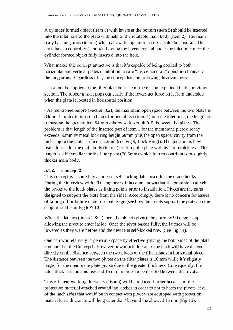
In order to attach the pivot supporter to the pivot (to hold the pivot), only one sling with
pivot supporter will be hanging down from lifting beam between the plates (Fig 19 step
1). Next, the operator will pick up the other hanging sling with extra device so that the
pivot supporter will be placed under the pivot (Fig 19 step 2). From perspective of
stability, it would be better if the pivot supporter didn’t consist of different parts but of one
whole/ solid entire body.
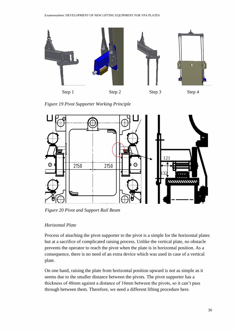
To attach the pivot supporter around the pivot, it should pass between pivot and rail beam
(Fig 20) where a very limited room is allowed to pass by; length from bracket (on the plate)
to shaft of slide block (connected to pivot) is 121mm and height from pivot to top of the rail
beam is 132 mm. As seen in Fig 18, a flexible device made of a several pieces which are
rotatable around their axes relative to each other can pass through easier than a device built
as one solid body. That’s why a double-hinge type pivot supporter is chosen as a most
appropriate device for this condition.
In next step, the operator will put the other sling over the lifting beam hook (Fig 19 step 3).
Step 1-4 will be repeated at the other side of the plate if there is only one operator or these
steps can be performed at the same time when more than one operator are available (Fig 19
step 4).
Examensarbete: DEVELOPMENT OF NEW LIFTING EQUIPMENT FOR VPA PLATES
30
Horizontal Plate
Process of attaching the pivot supporter to the pivot is a simple for the horizontal plates
but at a sacrifice of complicated raising process. Unlike the vertical plate, no obstacle
prevents the operator to reach the pivot when the plate is in horizontal position. As a
consequence, there is no need of an extra device which was used in case of a vertical
plate.
On one hand, raising the plate from horizontal position upward is not as simple as it
seems due to the smaller distance between the pivots. The pivot supporter has a
thickness of 48mm against a distance of 16mm between the pivots, so it can’t pass
through between them. Therefore, we need a different lifting procedure here.
121
132
Step 1 Step 2 Step 3 Step 4
Figure 19 Pivot Supporter Working Principle
Figure 20 Pivot and Support Rail Beam

Examensarbete: DEVELOPMENT OF NEW LIFTING EQUIPMENT FOR VPA PLATES
31
Figure 21 Pivot Supporter for the Horizontal Filter Plates
Having less thickness than 16mm, the sling is able to be placed between the pivots first
(Fig 21 A). It’s considered that the other ends of the slings are already placed over the
hooks of the lifting beam (which is not seen in the figure above). Once the lifting beam
starts to pull up the slings, the plate rises upward and as a result, a sufficient room will
be provided for the sling connector to pass fully the pivot. Now the plate is ready to be
lifted up with lifting beam which in turn hangs from the crane as/ since the pivot
supporter is in right place where it should be (Fig 21 B).
More detailed drawings of the pivot supporter with clevis pins are found in Fig 38 and
Fig39 of Appendix C.
Sling
The four webbing slings, a couple of a pair of slings at each side of the plate, are used to
connect the pivot supporter to the hooks of the lifting beam in total. The webbing slings
are made of usually high-strength synthetic fibers such as nylon, polypropylene or
polyester.
The sling has two eyes at both ends; the lower one is threaded through the pivot
supporter (sling connector) while the upper one is hung over the lifting beam hook. The
upper eye is rotated 90° to the plane of the main body so that the sling body needn’t to
be twisted during the lifting operation (Fig 22). When the sling with eye terminations is
in use, consideration must be taken to ensure that the length of eye is not too short in
regard to diameter of the object within it so that the internal angle of the sling eye

Examensarbete: DEVELOPMENT OF NEW LIFTING EQUIPMENT FOR VPA PLATES
32
doesn’t exceed 20°25
; the eye length(s), designed after the standard, is 3-5 times greater
than the diameter of the object within it (sling connector and lifting beam hook are the
objects inside the sling eyes).
The standard thickness of the webbing sling for <500kg load is considered to be around
7mm26
. However, extra layers which have same thickness as the sling are recommended
to be sewn to the sling at wear points on either or both sides of the sling body. Due to
the lowering or tilting applications where friction between sling and plate is of
importance, the sling body should be protected with extra layers throughout its length
and breadth in the same manner as sling eyes are done.
It’s recommended to use approximately 3m sling from lower sling eye to upper sling
eye. This dimension can be referred to as distance between the pivot where the lower
eye is attached and lifting beam hook where upper eye is attached. The lifting beam and
operator on the top plane must be on same level so that the latter can reach the former
without (great) suffering. (This level is the most appropriate height for an operator to
hang the sling over the lifting beam hook from inside handrail on the top plane (see Fig
19 Step 3)). Therefore, sling with excessively long or short length will result in greater
level difference between operator and lifting beam possibly causing a possible fall of
operator from the top plane.
The webbing sling provides all the above mentioned conditions (length, sling eye type
& length etc) will be purchased.
Figure 22 Sling eyes face different directions
Sling eye dimension can be found in Fig 40 from Appendix C.
Lifting Beam with double hooks
The lifting beam with double hooks (Fig 23) can be purchased and manufactured locally
considering shipping/ transportation cost from Sweden to Australia.
25
Gunnebo Industries AB, Information for safe use and maintenance of flat polyester webbing slings,
Gunnebo Industries AB [website],
<http://www.gunneboindustries.com/Global/Lifting/User%20instruction/Information%20for%20safe%20
use%20and%20maintenance%20of%20flat%20polyester%20webbing%20sling.pdf>, accessed 8 Nov.
2015. 26
F. D. Lake Co., Web Slings, F. D. Lake Co. [website], <http://www.fdlake.com/webslingtro.html>,
accessed 2 Nov. 2015.
Examensarbete: DEVELOPMENT OF NEW LIFTING EQUIPMENT FOR VPA PLATES
33
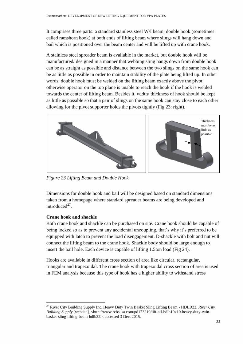
It comprises three parts: a standard stainless steel W/I beam, double hook (sometimes
called ramshorn hook) at both ends of lifting beam where slings will hang down and
bail which is positioned over the beam center and will be lifted up with crane hook.
A stainless steel spreader beam is available in the market, but double hook will be
manufactured/ designed in a manner that webbing sling hangs down from double hook
can be as straight as possible and distance between the two slings on the same hook can
be as little as possible in order to maintain stability of the plate being lifted up. In other
words, double hook must be welded on the lifting beam exactly above the pivot
otherwise operator on the top plane is unable to reach the hook if the hook is welded
towards the center of lifting beam. Besides it, width/ thickness of hook should be kept
as little as possible so that a pair of slings on the same hook can stay close to each other
allowing for the pivot supporter holds the pivots tightly (Fig 23: right).
Dimensions for double hook and bail will be designed based on standard dimensions
taken from a homepage where standard spreader beams are being developed and
introduced27
.
Crane hook and shackle
Both crane hook and shackle can be purchased on site. Crane hook should be capable of
being locked so as to prevent any accidental uncoupling, that’s why it’s preferred to be
equipped with latch to prevent the load disengagement. D-shackle with bolt and nut will
connect the lifting beam to the crane hook. Shackle body should be large enough to
insert the bail hole. Each device is capable of lifting 1.5ton load (Fig 24).
Hooks are available in different cross section of area like circular, rectangular,
triangular and trapezoidal. The crane hook with trapezoidal cross section of area is used
in FEM analysis because this type of hook has a higher ability to withstand stress
27
River City Building Supply Inc, Heavy Duty Twin Basket Sling Lifting Beam - HDLB22, River City
Building Supply [website], <http://www.rcbsusa.com/pd173219/lift-all-hdlb10x10-heavy-duty-twin-
basket-sling-lifting-beam-hdlb22>, accessed 3 Dec. 2015.
Thickness
must be as
little as
possible
Figure 23 Lifting Beam and Double Hook

Examensarbete: DEVELOPMENT OF NEW LIFTING EQUIPMENT FOR VPA PLATES
34
developed at critical areas than that of other types of hooks according to the several
studies28
.
Figure 24 Crane Hook with Shackle
See detailed dimensions on the crane hook as well as shackle in Fig 41-42 in Appendix
C.
Grabber
The grabber is not a lifting device itself but a supporting item which is designed to help
new lifting equipment to lift up the plates in vertical position.
The operator from the top plane will use this device to pick up the other side of the
pivot supporter with sling from underside of the pivot so that the pivot supporter is
around the pivot (Fig 19 Step 2), i.e. the grabber functions as an extended arm for the
operator.
The grabber can be either purchased (selected from available items) or manufactured or
ordered from suppliers. The arm should be a long enough to reach from the top plane to
the pivot. The protection rubber material is necessary for the hook part because it often
meets the pivot and pivot supporter which made of metals.
The grabber can possibly be used for different purposes as the operator has a limited
access to the plates inside VPA machine; for instance, to utilize it in Step 3 (Fig 19) in
case the lifting beam hook is beyond the reach for the operator.
See some examples of the grabber in Fig 25.
28
Benkar, Chetan N. & Wankhade, N.A, FINITE ELEMENT STRESS ANALYSIS OF CRANE HOOK
WITH DIFFERENT CROSS SECTIONS, International Journal For Technological Research In
Engineering, Volume 1, Issue 9, May-2014, pp. 868-872.
Figure 25 Grabber and Sticker

Examensarbete: DEVELOPMENT OF NEW LIFTING EQUIPMENT FOR VPA PLATES
35
6. Analytical and Numerical Analysis for
Lifting Equipment
The objective of this chapter is to investigate whether the designed components of the
lifting device act in accordance with the theoretical knowledge described in Chapter 2.
Even FEM structural analysis is performed on the both whole package of the load and
the pivot solely in the end of the Chapter partly to discover the critical points on the
latter and partly to support the result of the analytical calculations.
6.1. Shear Stress in Lifting Beam
6.1.1. To compute shear force in lifting beam
Load diagram
Lifting beam length
Length between two attachments
= crane hook pulls the lifting beam upwards
= slings around the pivots pull the lifting beam downwards
↑:
The plate is symmetrically lifted with lifting beam, so . This leads to:
(6.1)
The membrane plate mass can be rounded to 600kg (actual mass is 575kg). In order to
simplify the calculation, acceleration of gravity is rounded to 10 m/s2 as well:
From equation (6.1):

Examensarbete: DEVELOPMENT OF NEW LIFTING EQUIPMENT FOR VPA PLATES
36
Shear and Moment Diagram
Shear and moment diagrams help to determine the value of shear force and bending
moment at a given point in the lifting beam. The lifting beam should be broken in a
several segments so that shear and moment values will be specified at all change of
loading positions.
↑: shear force at cross section along the y-axis
→: normal stress at cross section along the x- axis
: bending moment at cross section
Break1:
↑:
→:
:
Break2:
↑:
→:
: -
When , the moment will be:
When , the moment will be:
Break3:

Examensarbete: DEVELOPMENT OF NEW LIFTING EQUIPMENT FOR VPA PLATES
37
↑:
→:
: -
When , the moment will be:
When , the moment will be:
Break4:
↑:
→:
: -
Shear and moment diagram will be plotted according to the values obtained above:

Examensarbete: DEVELOPMENT OF NEW LIFTING EQUIPMENT FOR VPA PLATES
38
As seen from shear and moment diagram, the maximal bending moment is obtained at
middle of the lifting beam at which the maximal shear force is .
6.1.2. To compute First Moment of Area
Using equation (2.2), first moment of area on the I-shape beam is calculated as below:
6.1.3. To compute Moment of Inertia
Equation (2.3) gives:
Width of Section
Shear Diagram Moment Diagram

Examensarbete: DEVELOPMENT OF NEW LIFTING EQUIPMENT FOR VPA PLATES
39
Shear stress can be computed according to Equation (2.1) since all the variables are
known now:
On the other hand, maximum allowable stress in the steel material (1.0038) is calculated
with Equation (2.5):
Result: shear stress in the lifting beam
is sufficiently less than
maximum allowable stress
→ Safe to use!
6.2. Shear Stress in Pin
Tension in one sling connecter is expressed as
.
The pin fits snugly in the hole of the pivot supporter, so the pin diameter is identical to
the diameter of the hole in the pivot supporter, d = 24mm. If we define P as a force
applied on each sling, then P is equal to T/2:
According to the equation (2.6),
When the plate is being raised from or lowered to the horizontal position, only one sling
connector member with its other pair will support the plate which suppress with its full

Examensarbete: DEVELOPMENT OF NEW LIFTING EQUIPMENT FOR VPA PLATES
40
weight on it. Consequently, shear stress for the pin will be doubled followed by doubled
applied force on it in this case:
If the pin is considered to be steel as the pivot supporter, the maximum allowable stress
of can be used in estimating the maximum safe load on it.
Result: → Safe to use!
→ Safe to use!
6.3. Tensile and Bending Stresses in Different Pivot
Supporter Parts
To compute tensile strength applied at either sling connector with Equation (2.4):
(see shear stress in pin)
Result: → Safe to use!
→ Safe to use!
Thus, as stated previously, tensile strength occurred at side part due to the load is
ensured to be less than the maximum allowable stress.
To compute compressive stress at base part from Equation (2.4):
Effective area which subjected to force due to the pivot is
P
Figure 26 Sling Connector and Section

Examensarbete: DEVELOPMENT OF NEW LIFTING EQUIPMENT FOR VPA PLATES
41
→ Safe to use!
Calculation
The Equations (2.7)-(2.9) used to identify the adequate WLL can be applied to our case.
The plate is symmetrically lifted up with four slings of the same length.
Using (2.7), (Note: Headroom and sling length are established at
approximately same length)
Using (2.8),
Using (2.9),
The number of sling legs will be halved when the plate is either lowered to the
horizontal plane or raised up from the horizontal plane:
As shown in Table 4, the minimum working capacity for a single webbing sling is
( OK)
Table 4 Sling Chart29
6.4. Welding Calculation
The welding theory described in subsection 2.2.5 will be applied in computing of
sufficient weld throat which is necessary to sustain the whole load (plate) with spreader
beam.
29
Bash-P International Ltd, Webbing Sling Load Chart - Bash-P International, Bash-P International Ltd
[website], <http://bashpint.com/webbing_sling_load_chart_soft_eye.php>, accessed 18 Oct. 2015.

Examensarbete: DEVELOPMENT OF NEW LIFTING EQUIPMENT FOR VPA PLATES
42
Total load of the plate, lifting beam, slings and other accessories hanging from the
lifting lug is (each mass of the items are obtained from Table 8):
if the fillet weldment is executed along the whole length of the lifting lug
(Fig 52 in Appendix F).
Combining equations (2.12) and (2.13), the following expression will be obtained:
According to the Table 10 (Appendix F), design strength of carbon steel 1.0038 (S235)
is equal to 360MPa (
).
The weld throat a must be:
A small weld throat ( ) results in the reasonable cost followed by the little
weld amount.
We will check if the second condition (2.14) is satisfied with the specified weld throat
below. First, it’s necessary to compute
using correlation factor obtained from Table
11:
.
Since the both conditions satisfied, welding with weld throat and length of
is sufficient to hold the plate including the spreader beam and other accessories.
6.5. Finite Element Analysis (FEM)
Finite Element Analysis is widely accepted in all engineering disciplines as finite model
can be represented in a detailed structure with greater precision than conventional
simplified hand calculations. Since actual shape, constraints, as well as material
properties can be specified with greater accuracy than that used in hand calculation, the
numerical analysis should be regarded as more reliable than analytical analysis.

Examensarbete: DEVELOPMENT OF NEW LIFTING EQUIPMENT FOR VPA PLATES
43
The objective of this section is to perform a simulation on the configuration of designed
system and to determine its real world behavior under identical environment where it’s
going to be used. Once the analysis is completed, the feasibility of the new design will
be evaluated focusing on the pivot supporter and identify the critical stress and fail points.
In addition, displacement and safety factor information will be obtained.
The lifting analysis is performed using the Autodesk Inventor Simulation Software.
Structural and Material Details
The plate used in the simulation has a simplified design than the actual one at the plant.
Due to design modification, the weight increases up to around 600 kg which is heavier
than the actual plate. The rest of the structural dimensions such as height, length, width
and depth are kept same.
The desired material EPDM for the rubber protection was not on the list. Therefore, a
butyl rubber instead of EPDM is selected for it under simulation running. Both
materials have similar mechanical properties (Table 5), so simulation results wouldn’t
differ in a great extent in case EPDM was selected. For same reason, a nylon 6.6 is
defined for the webbing sling (Table 6). Material for lifting beam as well as pivot
supporter will be high strength steel with yielding stress of 320MPa.
Table 5 Comparison of EPDM and Butyl Rubber 30
EPDM Rubber Butyl
Young’s Modulus 1.45E+03 2.901E+02
Poisson’s Ratio 0.50 0.44
Yield Strength (MPa) 21.99 15.002
Tensile Strength (MPa) 27.5997 15.002
Table 6 Comparison of Polyester and Nylon 6.631
Polyester Nylon 6.6
Modulus of Elasticity (GPa) 2.06 – 4.41 1.59 – 3.79
Poisson’s Ratio 0.37 – 0.44 0.39
Yield Strength (MPa) 59 – 100 55.1 – 82.8
Tensile Strength (MPa) 41.4 – 89.7 94.5
Density (g/cm3) 1.04 – 1.46 1.14
6.5.1. Lifting Equipment Arrangement Simulation
Von Mises Stress
Von Mises stress is used to check whether the design is able to withstand a given load.
The lifting equipment is subjected to none other than the gravity load due to the plate.
No critical stress was recognized on the lifting beam or pivot supporter except at the
following points of shackle and crane hook.
30
Ibid., p. 28. 31
Ibid., p. 28.

Examensarbete: DEVELOPMENT OF NEW LIFTING EQUIPMENT FOR VPA PLATES
44
The max critical stress found on the shackle is 88.1MPa out of 234.2MPa which is approx.
38% of maximum stress. On the other hand, 199MPa stress is found on the tip of the crane
hook where the latch sits (see Fig 43 in Appendix D).
Displacement
The plate is displaced down with 0.44mm at maximum due to the stretch/ elongation of the
nylon slings caused by the load. This very small displacement assumes that there is no
significant deformation followed by changed stiffness occurs at any of the individual
components during loading (see Fig 44 in Appendix D).
Safety Factor32
Generally, it’s considered to be safe if a safety factor is larger than 1 at a location in the
material and failed if it’s less than 1. The safety factor of 5 is our goal while 4 is common
for many applications.
As one can see for a blue color in Fig 45 in Appendix D, this new arrangement of lifting
system has exceeded our target of having a safety factor 5.
6.5.2. Pivot Supporter Simulation
Except the pivot supporter, all of the equipment components including lifting beam with
hook, sling, crane hook and shackle are designed according to the standards.
Consequently, there is no need of running FEM analysis on those different members
separately. On the other hand, in order to have a closer look at what really happens with
pivot supporter when it’s subjected to the load, it’s effective to carry out FEM
simulation solely on the pivot supporter.
FEM Result
Applied force used during the simulation on each pivot supporter is established as
follows:
The critical stress points identified at the different parts of pivot supporter is summarized in
Table 7:
Table 7 Pivot Supporter FEM Result
Part Name Sling connector Side Base
Location
Inner corners of upper side
where webbing sling threads
through (Fig 46 in Appendix D)
Lower edges of the
pin hole (Fig 46 in
Appendix D)
-
Marked Stress 27.98MPa 18MPa Below
32
Radu Stancescu, Accurately Report the Factor of Safety in Autodesk Simulation Multiphysics,
Cadalyst [website], <http://www.cadalyst.com/cad/inventor/accurately-report-factor-safety-autodesk-
simulation-multiphysics-14723>, accessed 29 Oct. 2015.

Examensarbete: DEVELOPMENT OF NEW LIFTING EQUIPMENT FOR VPA PLATES
45
(out of 34.92MPa) (out of 34.92MPa) 13.97MPa
The relatively sharp corners and presence of holes has acted as stress concentrators in
the side and sling connector parts. It’s assumed that reductions in area due to the hole
for the sling or clevis pins contribute to the localized increase in stress. On the other
hand, there is no critical stress is recognized on the base part regardless of several holes
in its structure (Fig 46 in Appendix D).
As regarding to displacement and safety factor, the rubber protection material (rather
than the members of the arrangement) is severely subjected to the applied force. The
minimum safety factor identified on the pivot supporter is marked with 7.5 out of 15 which
exceeds the required safety factor issued by customer (7.5 > 5). These minimum safety
factors are discovered on the base rubber protection and corners of sling connector (Fig 47-
48 in Appendix D).

Examensarbete: DEVELOPMENT OF NEW LIFTING EQUIPMENT FOR VPA PLATES
46
7. Cost Analysis
Cost Analysis consists of two parts: manufactured and purchased.
Manufactured: The former includes the designed products which will be manufactured/
constructed in China eventually. According to cost contract, the manufacturing and
labor cost including material price per 1kg is estimated as 2.67 US dollar (2015). The
only component that will be manufactured in China by Metso is a pivot supporter with
rubber protections.
Purchased: The rest of the lifting arrangements are either purchased locally or ordered
at suppliers in Australia mainly to save transportation cost. Therefore, webbing slings,
crane hook and shackles will be purchased in the customer’s country. Generally, it’s
considered to be a cost-beneficial to contact local suppliers instead of delivering heavy
products such as lifting beam to long destination. However, it could be opposite in some
cases where sum of the manufacturing and delivery cost falls below the amount of
purchase price.
Accordingly, the lifting beam can be either purchased or manufactured:
To order the lifting beam at local supplier in Australia
To manufacture it in China and ship to Australia
Alternative A: The lifting/ spreading beam price varies depending on a number of
factors such as how many items are being purchased, what kind of material is used and
what loading capacity it has and so on. In addition, it varies a lot geographically also.
However, an average price for the spreader beam can be estimated according to the
criteria established by W.W.Grainger33
which offers industrial supplies on and offline.
Estimated price will be calculated once the desired working load limit, spreader
maximum length and headroom are filled in.
Figure 27 Lifting Beam Price34
The search result shows that the lifting beam that’s the most appropriate for our
application will cost 1,474.00 USD per each (Fig 27).
33
Wikipedia, W. W. Grainger, Wikipedia the free encyclopedia [website],
<https://en.wikipedia.org/wiki/W._W._Grainger>, accessed 7 Oct. 2015. 34
Caldwell, WP161552 Fixed Spread Lifting Beam, W.W. Grainger Inc [website],
<https://www.grainger.com/product/CALDWELL-Fixed-Spread-Lifting-Beam-WP161552/_/N-
mt0?s_pp=false&picUrl=//static.grainger.com/rp/s/is/image/Grainger/39RK28_AS01?$smthumb$>,
accessed 13 Nov. 2015.

Examensarbete: DEVELOPMENT OF NEW LIFTING EQUIPMENT FOR VPA PLATES
47
As described previously, it’s difficult to know the exact price for other components
since the price differ greatly from website to website.
The total price:
Web sling35
= 23.30USD (WLL x Length: 1T x 3M)
Shackle 36
= 15.00USD (WLL: 800kg)
Crane Hook37
= 113.85USD (WLL: 5T)
Lifting beam = 1474.00USD
Total = 1626.15USD = 13009.20SEK (> 5000SEK)
Note: total price calculated here can be less or more than the actual price since there is
no way of defining the actual total price for the components included in the arrangement.
Alternative B: If the lifting beam is decided to be manufactured in China, it will cost
less than buying locally regardless of the shipping cost. Here illustrates total price for
the whole arrangement if they would be manufactured in China.
Table 8 Price Chart
Price
Component Material Piece Total mass (kg)
Price per kg (USD/kg)
Total price (USD)
Rubber protection
Rubber side x2 sling connector x2 base x1
0.2 2.67 0.534
Pivot Supporter 1,0038 side x2 sling connector x2 base x1
32 2.67 85.44
Lifting beam including hooks
Steel 1.0038
x1 110 2.67 293.7
Shackle Steel 1.0038
x1 0.4 2.67 1.068
Hook(crane) Steel 1.0038
x1 0.37 2.67 0.9879
Slings Nylon x4 4.4 2.67 11.748 Total 393.4779
35
Xinto Co, 1TX3M 6:1 flat webbing sling lifting sling polyester fibre sling, AliExpress [website],
<http://www.aliexpress.com/item/1TX3M-flat-webbing-sling-lifting-sling-polyester-fibre-sling-lifting-
strap-towing-rope-winch-rope-crane/32493396062.html?spm=2114.40010508.4.37.HQoKwa>, accessed
17 Nov. 2015. 36
eBay, 2 x 7 Ton D Link Towing Lifting Shackle, eBay [website], <http://www.ebay.co.uk/itm/2-x-7-
Ton-D-Link-Towing-Lifting-Shackle-/262284642650s>, accessed 14 Dec. 2015. 37
W.W. Grainger Inc, Lifting Hook with Safety Latch 5 Ton, W.W. Grainger Inc [website],
<https://www.grainger.com/product/GRAINGER-APPROVED-Lifting-Hook-with-Safety-Latch-
26JX58?s_pp=false&picUrl=//static.grainger.com/rp/s/is/image/Grainger/26JX58_AS01?$smthumb$>,
accessed 9 Nov. 2015.

Examensarbete: DEVELOPMENT OF NEW LIFTING EQUIPMENT FOR VPA PLATES
48
As presented in Table 8, total price would be 393.4779USD = 3147.8232SEK
(<5000SEK).

Examensarbete: DEVELOPMENT OF NEW LIFTING EQUIPMENT FOR VPA PLATES
49
8. Conclusions and Recommendations for
Future Work
8.1. Conclusions
The designed lifting equipment comprises conventional lifting devices like lifting beam,
sling, shackle, crane hook in addition to the “pivot supporter”.
Thanks to the long slings from the spreader beam, the operator was allowed to work
outside the filter machine. In addition, all the four slings help the plate to stay stable
during the lifting operation by enclosing it from both sides. In order to avoid the sling
wear due to the friction with outlet corners and hooks, the slings were equipped with
extra layers so that they won’t be broken easily.
Since the sling can’t be formed in choker hitch around the pivot without the operator’s
closer presence to the pivot, something that holds the pivot tightly was necessary to be
designed. As a result, a lifting device called pivot supporter was designed in order to
ensure the compliance with requirements described in Section 5.3 (Page 29). The pivot
supporter around the pivot holds it tight so that the plate can be handled in a safer way
and allows the operator to operate in work zones. It consists of the three parts which can
move freely with respect to each other. This hinge design helps the pivot supporter to
pass through the limited space between the pivot and rail beam (Fig 20). The pivot
supporter was equipped with rubber protection materials not to harm the pivot since it
directly attached to the pivot.
The lifting beam with ramshorn hook at both ends was used to lift up the plate with help
of the slings. The positions of the double hooks on the lifting beam should be
considered carefully so that the slings hang down from the hooks will not be tilted to the
sides. Besides it, thickness of the ramshorn hook should be kept as little as possible
otherwise unnecessary thicker design put the pivot supporters at risk of opening wide
followed by the slings (remember that the pivot supporters around the pivot should be
held tight).
As for the crane hook and shackle, they will be purchased at the site. Shackle should be
chosen in a manner that the lifting lug can be fitted into the shackle body.
Although the new lifting equipment has fulfilled the safety requirements, there is still
room for improvements regarding the design. As mentioned in Horizontal Plate of
Section 5.3, an issue related to the operation of lowering the plate to the ground was left
unsolved. When the plate is lowered onto the ground, the two of the slings are happened
to be laid under the plate (more correctly, under the upper outlet corners) and the slings
are forced to be dragged from the underside of the plate.
Each individual component is described in separate subsections in order to have a closer
look at the members. Furthermore, manual calculations were made on the lifting beam,
sling, pivot supporters and the lifting lug (bail) to investigate to what degree the

Examensarbete: DEVELOPMENT OF NEW LIFTING EQUIPMENT FOR VPA PLATES
50
designed parts can be feasible or reliable for the specific application. According to the
calculation results, all of the lifting equipment parts are feasible for handling of the
VPA plates and all the stresses occurred in each component are far lower than the
maximum allowable stresses (Chapter 6). Welding calculation made on the lifting lug
indicates that a very small amount of the welding is sufficient to lift up the whole load
including the plate and lifting beam.
Besides it, FEM analysis was performed to compare an analytical analysis with
numerical one. It has reached a conclusion that FEM result supports the manual
calculation in large extent. However, some critical points are discovered on the pivot
supporter around its corners. As those critical points are impossible to be discovered
with simple manual calculations, the results of FEM analysis should to be taken
seriously in the later manufacturing stage of the pivot supporter.
Lastly, a cost analysis is carried out to examine if the economical requirement has been
fulfilled. Pivot supporter is going to be manufactured in China according to the special
contract with Metso whereas the rest of the components are going to be ordered locally.
As for the lifting beam, it can be either manufactured in China or purchased in Australia
depending on which alternative is cost-beneficial. Alternative B cost less than
Alternative A as far as we believe the price suggestions described in Chapter 7 are close
to the actual prices.
8.2. Recommendations for Future Work
Although the new lifting system presented in the thesis have demonstrated safer and
relatively robust mechanism compared to the conventional fiber method, it could be
further developed in a various ways:
Adjustable Lifting Beam: In the new lifting model, double-hook is attached
firmly to the beam ends. However, if the beam has the adjustable attachments, it can be
applied for the other plants and sites where the different types of the VPA plates are in
use.
To find a better solution for taking off the webbing slings from under the plate.
As described in Section 5.3, the slings are trapped under the load after lowering it on the
ground. It’s important to avoid situations where slings must be dragged from a load
resting on it.
According to the manual calculation, the pivot supporter is many times stronger
than it need to be. Since there is a very limited space for the pivot supporter under pivot
in the VPA filter, a modification of geometry is strongly recommended on the structure
so that it would have less volume.
Cost Analysis should be recorded in a more accurate and detailed way. Market
price for the lifting components such as shackle and crane hook must be calculated after
comparing a several prices at different suppliers. Even the current costs for the raw
material as steel, nylon or rubber should be examined carefully.
Examensarbete: DEVELOPMENT OF NEW LIFTING EQUIPMENT FOR VPA PLATES
51
Reference
Bash-P International Ltd, Webbing Sling Load Chart - Bash-P International, Bash-P
International Ltd [website],
<http://bashpint.com/webbing_sling_load_chart_soft_eye.php>, accessed 18 Oct.
2015.
Beardmore, Roy, Structural Design, Roymech [website], 17 Feb. 2013,
<http://www.roymech.co.uk/Related/Construction/Structural_connections.html>,
accessed 10 March 2016.
Benkar, Chetan N. & Wankhade, N.A, FINITE ELEMENT STRESS ANALYSIS OF
CRANE HOOK WITH DIFFERENT CROSS SECTIONS, International Journal
For Technological Research In Engineering, Volume 1, Issue 9, May-2014, pp.
868-872.
Bergman, Bo & Klefsjö, Bengt, Quality from Customer Needs to Customer Satisfaction,
3rd edn, Studentlitteratur AB, Poland, 2014.
Björk, Karl, Formler och tabeller för mekanisk konstruktion, Karl Björks Förlag HB,
Spånga, 2011.
Burge, Stuart, The Systems Engineering Tool Box, 2009,
<http://www.burgehugheswalsh.co.uk/uploaded/1/documents/pugh-matrix-
v1.1.pdf>, accessed 1 Nov. 2015.
Bushman Equipment Inc, Billet Tongs | Ingot Tongs | Ingot Lifter, Bushman Equipment
Inc [website],
<http://www.bushman.com/index.php/content/below_the_hook/tongs>, accessed
11 Nov. 2015.
Caldwell, WP161552 Fixed Spread Lifting Beam, W.W. Grainger Inc [website],
<https://www.grainger.com/product/CALDWELL-Fixed-Spread-Lifting-Beam-
WP161552/_/N-
mt0?s_pp=false&picUrl=//static.grainger.com/rp/s/is/image/Grainger/39RK28_A
S01?$smthumb$>, accessed 13 Nov. 2015.
Callister, William D.Jr, Materials Science and Engineering An Introduction, 7th edn,
John Wiley & Sons Inc., USA, 2007.
Dyson, John, Welding Calculations, Gowelding [website], 11 Feb. 2001,
<http://www.gowelding.com/calcs/>, accessed 11 March 2016.
eBay, 2 x 7 Ton D Link Towing Lifting Shackle, eBay [website],
<http://www.ebay.co.uk/itm/2-x-7-Ton-D-Link-Towing-Lifting-Shackle-
/262284642650s>, accessed 14 Dec. 2015.

Examensarbete: DEVELOPMENT OF NEW LIFTING EQUIPMENT FOR VPA PLATES
52
F. D. Lake Co., Web Slings, F. D. Lake Co. [website],
<http://www.fdlake.com/webslingtro.html>, accessed 2 Nov. 2015.
Gunnebo Industries AB, Information for safe use and maintenance of flat polyester
webbing slings, Gunnebo Industries AB [website],
<http://www.gunneboindustries.com/Global/Lifting/User%20instruction/Informati
on%20for%20safe%20use%20and%20maintenance%20of%20flat%20polyester%
20webbing%20sling.pdf>, accessed 8 Nov. 2015.
Gunnebo Industries, Sling hook EKN GrabiQ, SolidComponents [website],
<http://www.solidcomponents.com/company/out/3508014/Z101128.pdf>,
accessed 1 Dec. 2015.
Gunnebo Industries, Standard schackel Nr 835, SolidComponents [website],
<http://www.solidcomponents.com/company/out/3507951/A083513.pdf>,
accessed 1 Dec 2015.
Health and Safety Executive, What is lifting equipment? - Work equipment and
machinery, Health and Safety Executive [website], <http://www.hse.gov.uk/work-
equipment-machinery/lift-equipment.htm>, accessed 1 Oct. 2015.
Lift-It Manufacturing Company, Lift Planning and Evaluation, Lift-It Manufacturing
Company [website], <http://www.lift-it.com/slings_safety_use_inspection.pdf>,
accessed 21 Nov. 2015.
Marks’, Standard Handbook for Mechanical Engineers, 10th edn, McGRAW-HILL,
1996.
Metso Minerals (Sweden) AB, Operation and Maintenance Manual Pressure Filter
VPA 2040-54, Rev 0, Sweden, 2012.
Posilift Limited, Posilift-Vacuum Lifters, Posilift Limited [website],
<http://posilift.com/products.php?sid=46>, accessed 23 Oct. 2015.
Ricker, David T., Design and Construction of Lifting Beams, Engineering Journal /
American Institute of Steel Construction, 4th Quarter 1991.
River City Building Supply Inc, Heavy Duty Twin Basket Sling Lifting Beam -
HDLB22, River City Building Supply [website],
<http://www.rcbsusa.com/pd173219/lift-all-hdlb10x10-heavy-duty-twin-basket-
sling-lifting-beam-hdlb22>, accessed 3 Dec. 2015.
Stancescu, Radu, Accurately Report the Factor of Safety in Autodesk Simulation
Multiphysics, Cadalyst [website],
<http://www.cadalyst.com/cad/inventor/accurately-report-factor-safety-autodesk-
simulation-multiphysics-14723>, accessed 29 Oct. 2015.

Examensarbete: DEVELOPMENT OF NEW LIFTING EQUIPMENT FOR VPA PLATES
53
The Goodheart-Willcox Co, Weld Joints 6 and Weld Types, The Goodheart-Willcox Co
[website] <http://www.g-w.com/pdf/sampchap/9781590708668_ch06.pdf>,
accessed 9 March 2016.
The University of Arizona, Shear Stresses in Beams, The University of Arizona
[website],
<http://fp.optics.arizona.edu/optomech/references/OPTI_222/OPTI_222_W10.pdf
>, accessed 2 Nov. 2015.
Union, Wire Rope Sling Handbook, UnionRope [website],
<http://www.unionrope.com/Resource_/Pageresource/Union/Wireropeslingguide1
-09c.pdf>, accessed 18 Oct. 2015.
W.W. Grainger Inc, Lifting Hook with Safety Latch 5 Ton, W.W. Grainger Inc
[website], <https://www.grainger.com/product/GRAINGER-APPROVED-
Lifting-Hook-with-Safety-Latch-
26JX58?s_pp=false&picUrl=//static.grainger.com/rp/s/is/image/Grainger/26JX58
_AS01?$smthumb$>, accessed 9 Nov. 2015.
Wikipedia, Metso, Wikipedia the free encyclopedia [website],
<https://en.wikipedia.org/wiki/Metso>, accessed 1 Oct. 2015.
Wikipedia, Strength of materials, Wikipedia the free encyclopedia [website],
<https://en.wikipedia.org/wiki/Strength_of_materials>, accessed 9 Oct. 2015.
Wikipedia, W. W. Grainger, Wikipedia the free encyclopedia [website],
<https://en.wikipedia.org/wiki/W._W._Grainger>, accessed 7 Oct. 2015.
Xinto Co, 1TX3M 6:1 flat webbing sling lifting sling polyester fibre sling, AliExpress
[website], <http://www.aliexpress.com/item/1TX3M-flat-webbing-sling-lifting-
sling-polyester-fibre-sling-lifting-strap-towing-rope-winch-rope-
crane/32493396062.html?spm=2114.40010508.4.37.HQoKwa>, accessed 17 Nov.
2015.

Examensarbete: DEVELOPMENT OF NEW LIFTING EQUIPMENT FOR VPA PLATES
54
Appendix A
VPA Filter and Plate
Figure 28 VPA Top Plane View
Figure 29 Fiber strap (A) through the inlet hole (B)
Handrail

Examensarbete: DEVELOPMENT OF NEW LIFTING EQUIPMENT FOR VPA PLATES
55
Figure 30 Filter Plates with Notch
Figure 31 Plates in the wooden box
Notch

Examensarbete: DEVELOPMENT OF NEW LIFTING EQUIPMENT FOR VPA PLATES
56
Platform Proposal
Figure 32 Platforms around three VPA filters
Figure 33 Platform front view

Examensarbete: DEVELOPMENT OF NEW LIFTING EQUIPMENT FOR VPA PLATES
57
Figure 34 Platform side view
Figure 35 VPA filters

Examensarbete: DEVELOPMENT OF NEW LIFTING EQUIPMENT FOR VPA PLATES
58
Appendix B
Industrial Lifting Equipment
Figure 37 Example of Vacuum Lifter
Figure 36 Examples of Magnetic Lifter

Examensarbete: DEVELOPMENT OF NEW LIFTING EQUIPMENT FOR VPA PLATES
59
Appendix C
New Lifting Design
Figure 39 Clevis pin
Figure 38 Pivot supporter parts

Examensarbete: DEVELOPMENT OF NEW LIFTING EQUIPMENT FOR VPA PLATES
60
Figure 40 Webbing Sling

Examensarbete: DEVELOPMENT OF NEW LIFTING EQUIPMENT FOR VPA PLATES
61
Figure 41 Crane Hook38
Figure 42 Shackle39
38
Gunnebo Industries, Sling hook EKN GrabiQ, SolidComponents [website],
<http://www.solidcomponents.com/company/out/3508014/Z101128.pdf>, accessed 1 Dec. 2015.
39 Gunnebo Industries, Standard schackel Nr 835, SolidComponents [website],
<http://www.solidcomponents.com/company/out/3507951/A083513.pdf>, accessed 1 Dec 2015.
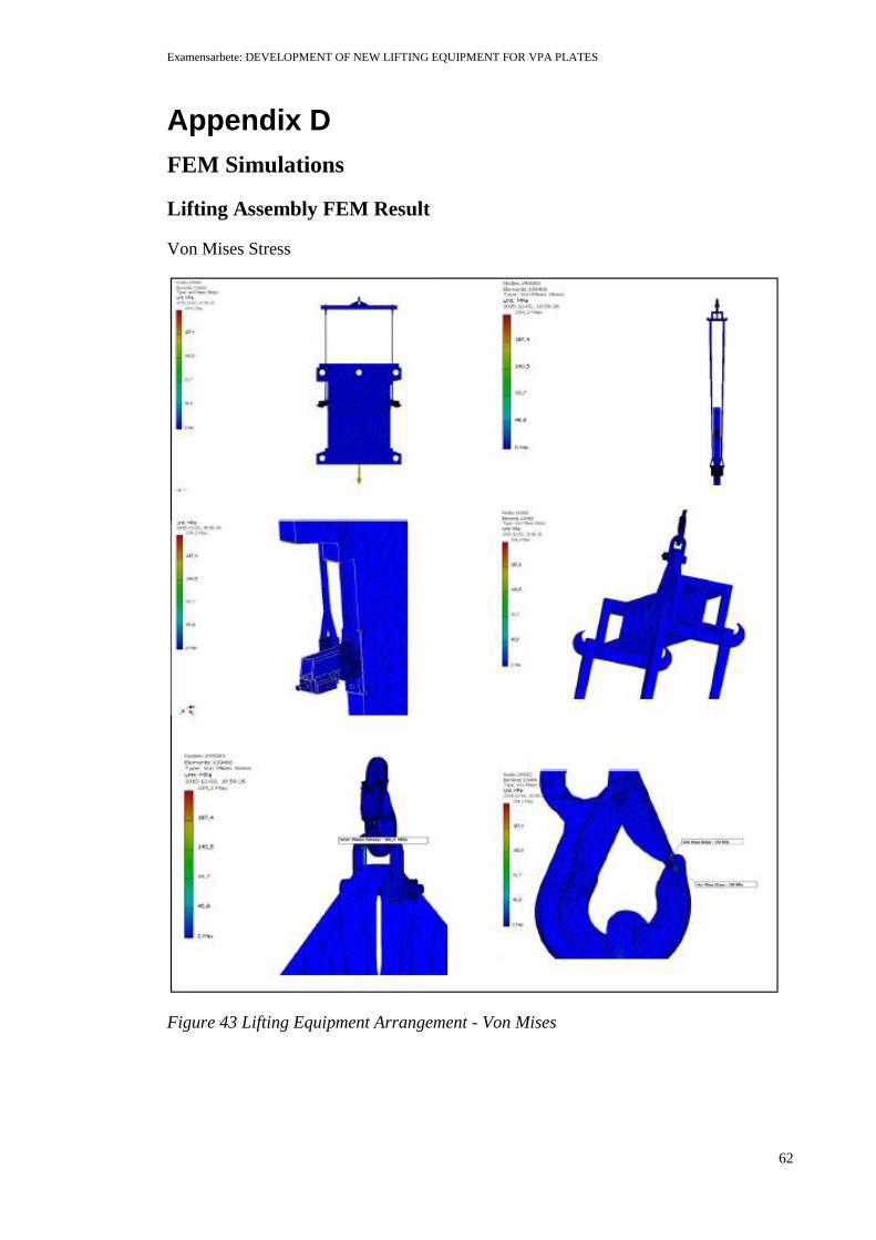
Examensarbete: DEVELOPMENT OF NEW LIFTING EQUIPMENT FOR VPA PLATES
62
Appendix D
FEM Simulations
Lifting Assembly FEM Result
Von Mises Stress
Figure 43 Lifting Equipment Arrangement - Von Mises

Examensarbete: DEVELOPMENT OF NEW LIFTING EQUIPMENT FOR VPA PLATES
63
Displacement
Figure 44 Lifting Equipment Arrangement - Displacement
Safety Factor
Figure 45 Lifting Equipment Arrangement - Safety Factor

Examensarbete: DEVELOPMENT OF NEW LIFTING EQUIPMENT FOR VPA PLATES
64
Pivot supporter
Von Mises
Figure 46 Pivot Supporter - Von Mises
Displacement
Figure 47 Pivot Supporter - Displacement

Examensarbete: DEVELOPMENT OF NEW LIFTING EQUIPMENT FOR VPA PLATES
65
Safety Factor
Figure 48 Pivot Supporter - Safety Factor

Examensarbete: DEVELOPMENT OF NEW LIFTING EQUIPMENT FOR VPA PLATES
66
Appendix E
Figure 49 Basket Hitch
Figure 50 Choke Hitch

Examensarbete: DEVELOPMENT OF NEW LIFTING EQUIPMENT FOR VPA PLATES
67
Appendix F
Table 9 Butt and T-joint welds40
Butt-joint (Fig 51: left) T-joint (Fig 51: right)
Square-groove butt weld Fillet weld
Bevel-groove butt weld Plug weld
V-groove butt weld Slot weld
J-groove butt weld Bevel-groove weld
U-groove butt weld J - groove weld
Flare -V- groove butt weld Melt – through weld
Flare-bevel - groove butt weld Flare-bevel - groove weld
Figure 51 Types of Butt and T-joint welds
Table 10 Design Strength for Various Materials41
40
Ibid., p. 10. 41
Ibid., p. 11.

Examensarbete: DEVELOPMENT OF NEW LIFTING EQUIPMENT FOR VPA PLATES
68
Table 11 Correlation Factors for various materials42
Figure 52 Lifting Lug Length
42
Ibid., p. 11.