examination paper for tmr4205 buckling and … of marine technology page 1 of 10 examination paper...
TRANSCRIPT

Department of Marine Technology
Page 1 of 10
Examination paper for TMR4205 Buckling and collapse of marine structures Academic contact during examination: Jørgen Amdahl Phone: 73595544 / 95745663 Examination date: 21.05.2013 Examination time (from-to): 09.00-13.00 Permitted examination support material: (D) – Neither printed nor
handwritten note as are permitted. Approved, simple calculator is permitted.
Other information: Language: English Number of pages: 10 Number of pages enclosed: 0
Checked by:
____________________________
Date
Signature

Department of Marine Technology
Page 2 of 10
PROBLEM 1
Figure 1
a) Figure 1shows the cross-section of a beam subjected to bending. Determine the
position of the plastic neutral axis and calculate the plastic section modulus for bending about the strong axis.
b) Sketch the stress distribution for pure plastic bending. Sketch in principle the stress distribution for combined plastic bending and axial force, when the axial force is relatively small (compared to the plastic axial force). How much does the presence of the axial force reduce the plastic bending capacity when the cross-section is subjected to an axial force of 0.9 MN? The yield strength of the material is fy = 300 MPa.

Department of Marine Technology
Page 3 of 10
Figure 2
c) Figure 2 shows a beam with two concentrated loads, with a magnitude of P and
2/3P, respectively. The plastic moment capacity of the beam is MP. The beam is fully clamped at A and simply supported at B. Sketch the potential collapse mechanisms. Determine the plastic collapse load for the mechanisms.
d) Select the critical mechanism (of those analysed in pt. c) and determine whether the associated collapse load is the true collapse load. If it is not the true collapse load, how is the calculated critical load compared to the true collapse load?
!!!!!!!!!!!!!
A! B!P! 2/3!P!
/3 /3 /3 �A!�/3 �A!

Department of Marine Technology
Page 4 of 10
PROBLEM 2 a) Sketch the principle force-end shortening relationship (or alternatively force-mid
point lateral displacement relationship) for a perfect, elastic column subjected to axial compression. In the same sketch plot also the corresponding relationship for an elastic column with imperfect geometry. What is the major challenge in estimating the Euler buckling stress for a compression member that is part of a structural system?
b) Sketch the principle force-end shortening relationship (or alternatively force-mid point lateral displacement relationship) for imperfect, elasto-plastic columns subjected to axial compression, one curve for a slender column and one curve for a stocky (small slenderness) column. Explain the reason for the difference between the two curves
c) A brace member of a jacket has been subjected to a relatively small ship impact. The
brace cross-section is not damaged, but the brace has got an out-of-straightness (lateral deformation) of 10% of the brace diameter. This is significantly larger than tolerance limit for fabrication of the member, and conventional (Ultimate Limit State) code checking does not apply. On the basis of linear elastic analysis it is found that the brace, which has an Euler buckling stress of 430 MPa, is subjected to axial stress of 190 MPa in damaged condition. Formulate a buckling/failure criterion that can be used for the bent brace, and check whether the brace satisfies this criterion. As this is a damaged condition, all partial safety factors can be taken equal to unity. For simplicity the radius of gyration can be taken equal to i ≈ 0.35D , where D = brace diameter. The yield strength of the brace material is fy = 300 MPa.
d) For non-flooded braces located in deep water there will be two constant stress components that are not necessarily included in a linear analysis of load effects. Which are they? How do these stress components affect the column buckling capacity of slender braces? In what way are they accounted for in column buckling checks of stocky (small slenderness) braces according to the ISO/NORSOK code? (A brief discussion is requested; no calculations shall be carried out)
e) Describe the reasoning behind the ISO/NORSOK code formulation for checking of deep water braces subjected to combined axial force and bending
Department of Marine Technology
Page 5 of 10
PROBLEM 3
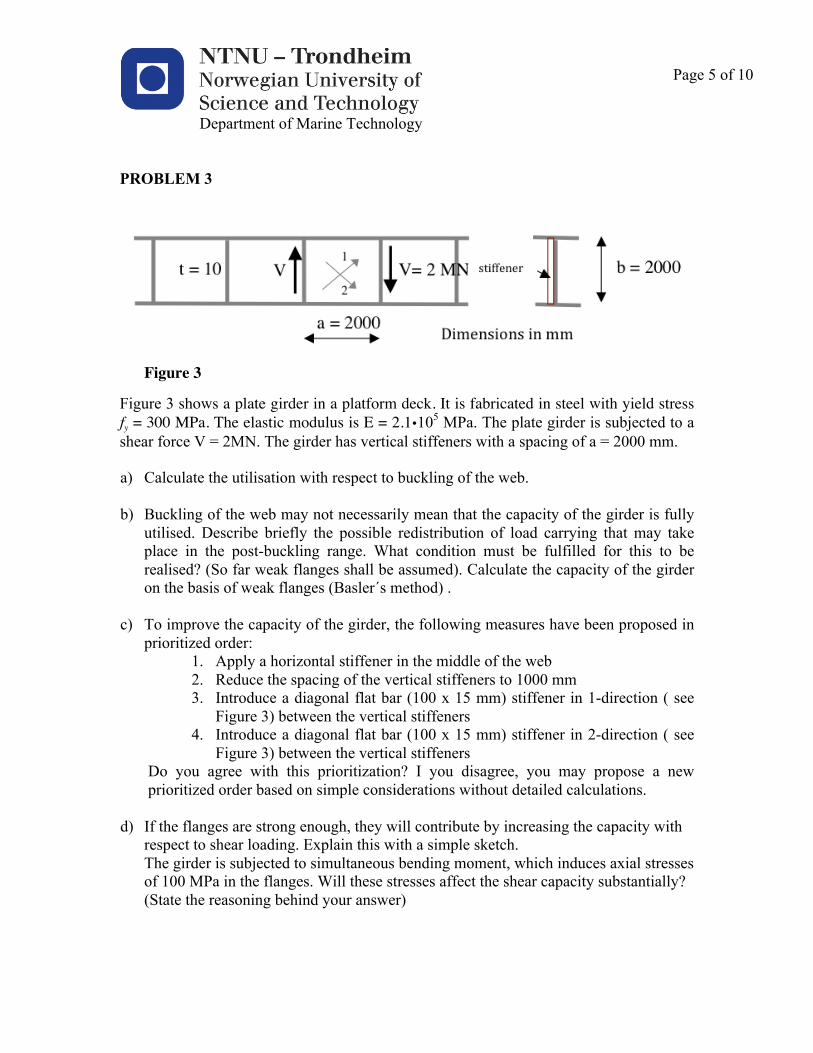
Figure 3
Figure 3 shows a plate girder in a platform deck. It is fabricated in steel with yield stress fy = 300 MPa. The elastic modulus is E = 2.1�105 MPa. The plate girder is subjected to a shear force V = 2MN. The girder has vertical stiffeners with a spacing of a = 2000 mm. a) Calculate the utilisation with respect to buckling of the web.
b) Buckling of the web may not necessarily mean that the capacity of the girder is fully
utilised. Describe briefly the possible redistribution of load carrying that may take place in the post-buckling range. What condition must be fulfilled for this to be realised? (So far weak flanges shall be assumed). Calculate the capacity of the girder on the basis of weak flanges (Basler´s method) .
c) To improve the capacity of the girder, the following measures have been proposed in
prioritized order: 1. Apply a horizontal stiffener in the middle of the web 2. Reduce the spacing of the vertical stiffeners to 1000 mm 3. Introduce a diagonal flat bar (100 x 15 mm) stiffener in 1-direction ( see
Figure 3) between the vertical stiffeners 4. Introduce a diagonal flat bar (100 x 15 mm) stiffener in 2-direction ( see
Figure 3) between the vertical stiffeners Do you agree with this prioritization? I you disagree, you may propose a new prioritized order based on simple considerations without detailed calculations.
d) If the flanges are strong enough, they will contribute by increasing the capacity with
respect to shear loading. Explain this with a simple sketch. The girder is subjected to simultaneous bending moment, which induces axial stresses of 100 MPa in the flanges. Will these stresses affect the shear capacity substantially? (State the reasoning behind your answer)

Department of Marine Technology
Page 6 of 10
Given information: Elastic section modulus
W = 4 4( 2 )
32D D t
Dπ ⎡ ⎤− −⎣ ⎦
Plastic section modulus
Z = 3 31 ( 2 )6D D t⎡ ⎤− −⎣ ⎦
Formulas related to buckling of beam-columns: Local buckling axial compression
2
1 0 0 412
1 047 0 274 0 412 1 382
1 382
cl
y
cl
y
cl ce
f . .ff . . . .f
f f .
= λ ≤
= − λ ≤ λ ≤
= ≤ λ
0 3xetf . Er
= , y
xe
ff
λ =
Column buckling
c2
y
f 0.9 for 1.34f
λλ
= >
21.0 0.28 for 1.34c
y
ff
λ λ= − ≤
( )2
2,y EE
f EIff k A
πλ = =l
Beam-columns - hydrostatic pressure included
0.52 2
1 1.01 1
my mya mz mz
a ach mh
Ey Ez
C Cf f
f f
σσ σσ σ
⎡ ⎤⎛ ⎞ ⎛ ⎞⎢ ⎥⎜ ⎟ ⎜ ⎟⎢ ⎥⎜ ⎟+ + =⎜ ⎟⎢ ⎥⎜ ⎟ ⎜ ⎟− −⎢ ⎥⎜ ⎟⎜ ⎟ ⎝ ⎠⎝ ⎠⎢ ⎥⎣ ⎦
use Cmz = Cmy = 1.0

Department of Marine Technology
Page 7 of 10
Local buckling - hydrostatic pressure included
2 2
1.0my mza x
cl mhf fσ σσ σ ++ + =
The ECCS design curve
1
1
x iox Y
x
E
AwW
σσ σσσ
+ =−
BV = τYbt crτ
Yτ+ 3
21− crτ
Yτ⎛⎝⎜
⎞⎠⎟
ba
⎡
⎣⎢⎢
⎤
⎦⎥⎥
Density of sea water: 1000 kg/m3 Acceleration of gravity: 10 m/s2
Maximum shear stress: Qrt
τπ
=
Stresses in closed cylinder under hydrostatic pressure:
2xpr prt t
= =θσ σ
Eσ =2π E
12 1− 2ν( )tb
⎛⎝⎜
⎞⎠⎟2
⋅ k λ = YσEσ
crσ =σY
1+ λ4
( )22
E 2
E t kb12 1
πτν
⎛ ⎞= ⋅⎜ ⎟− ⎝ ⎠ k = 5.34 + 4 b
a⎛⎝⎜
⎞⎠⎟2
λ = Yσ / 3
Eτ
crτ =
σY / 3
1+ λ4
Effective width:
ebb=
1.8β
−0.8
2β β ≥ 1
ebb= 1 β ≤ 1
β =bt
σY
E
Department of Marine Technology
Page 8 of 10
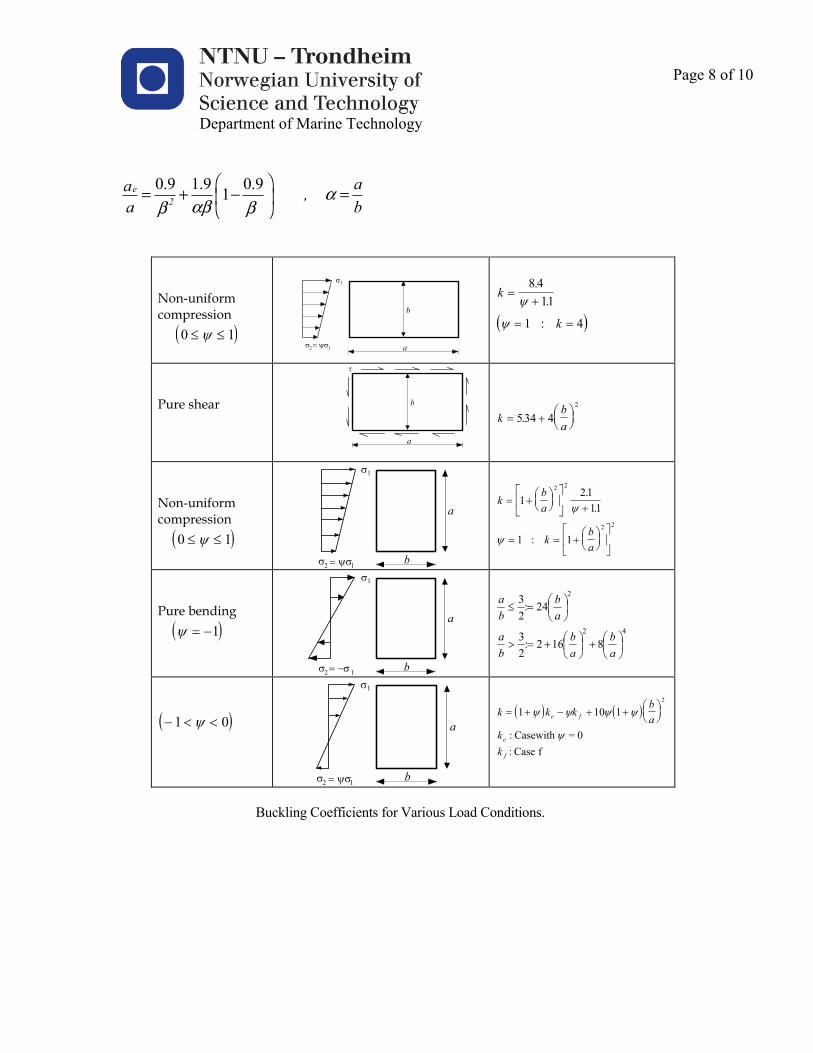
0.9 1.9 0.91e2
aa , a b
ααββ β
⎛ ⎞= + − =⎜ ⎟
⎝ ⎠
!
!"#$%&'(%)!*&)+!,(-#.*(%!&),/%0*$%'-!*.%#&*(%('*12343533'678'9:841'3;<14<<'
'"#$%!&'!()'&'!*(+%!&'!,-!&'!
!'
!!
!!"#$%&$'(#)*!+#*,)-..'#$!!!!!! ! "' &# #$ !!
!
!
"
%
% &'$%
&
. & !
!
! "
#
#
&(
& &
/ 0&&
& 0
11
2
$
$
!
!!/&)-!.0-1)!!!!
!!!!!!!!!!!!!!!
!
"
)
!
!!
#!"
& (*+,-./340 0.
1 !
!!"#$%&$'(#)*!+#*,)-..'#$!!!!! ! "' &# #$ !! !!!
"
!
%
% &'$%
&
. & !
!
#!"
#!"
& (*+,-./
0
12
3
45 (
& & (*+,-./
0
12
3
45
&.&&&
& &
. .
. .
11
2
$
$
!
!!/&)-!2-$3'$4!!!!! ! "$ & 6& !!!
"
!
%
% &'6%
&
. & !
!
0.
.
/&5.2.4
.02.4
/.-
,+*(/
.-
,+*(&7
/.-
,+*&#
"!
"!
!"
"!
!"
!
!!! "6 8 8& '$ !!!! !!!
"
!
%
% &'$%
&
. & !
!
! " ! "# # #!"
## $
% &
%
&
& ( 6 ( (*+,-./& &' &.
$ $ $ $
$226(7%!8#9: ; '6(7% -
!
!<=>?@#A+!6,%--#>#%A97!-,B!C(B#,=7!D,($!6,A$#9#,A71!
!!

Department of Marine Technology
Page 9 of 10
⎪⎪
⎭
⎪⎪
⎬
⎫
⎪⎪
⎩
⎪⎪
⎨
⎧
⎥⎥⎥⎥⎥⎥⎥⎥⎥⎥⎥⎥⎥
⎦
⎤
⎢⎢⎢⎢⎢⎢⎢⎢⎢⎢⎢⎢⎢
⎣
⎡ −−−
⎪⎪⎪
⎭
⎪⎪⎪
⎬
⎫
⎪⎪⎪
⎩
⎪⎪⎪
⎨
⎧
θ
θ
φ
φφ
φφφ
φφφφ
B
B
A
A
3
2253
4223
22532253
B
B
A
A
w
w
4EI
6EI12EI
2EI6EI4EI
6EI 12EI 6EI 12EI
=
M
Q
M
Q
Stiffness matrix with stability functions ( φ-factors
Compression Tension
( )
φφφ
φφφ
φφφ
φβφ
ββφ
215
214
213
1
2
2
1
23
21
43
4131
=
+−=
+=
−=
=
1
tan
( )
φφφ
φφφ
φφφ
φβφ
ββφ
215
214
213
1
2
2
1
23
21
43
4131
=
+−=
+=
−=
⎭⎬⎫=
1
tanh
lEI
NNN
2 2
2
EE
ππβ == ,

Department of Marine Technology
Page 10 of 10
Stability functions
-6
-5
-4
-3
-2
-1
0
1
2
3
4
5
-5 -4 -3 -2 -1 0 1 2 3 4 5
f-val
ue
Axial force r = N/NE
f4
f2
f3
f5
f1