example amba system user guide - arm...
TRANSCRIPT
Example AMBA™ SYstem
User Guide
Copyright © 1998-1999. All rights reserved.ARM DUI 0092C
Example AMBA SYstemUser Guide
Copyright © 1998-1999. All rights reserved.
Release Information
Proprietary Notice
ARM, the ARM Powered logo, Thumb and StrongARM are registered trademarks of ARM Limited.
The ARM logo, AMBA, PrimeCell, Angel, ARMulator, EmbeddedICE, ModelGen, Multi-ICE, ARM7TDMI, ARM7TDMI-S, ARM9TDMI, TDMI and STRONG are trademarks of ARM Limited.
All other products or services mentioned herein may be trademarks of their respective owners.
Neither the whole nor any part of the information contained in, or the product described in, this document may be adapted or reproduced in any material form except with the prior written permission of the copyright holder.
The product described in this document is subject to continuous developments and improvements. All particulars of the product and its use contained in this document are given by ARM Limited in good faith. However, all warranties implied or expressed, including but not limited to implied warranties or merchantability, or fitness for purpose, are excluded.
This document is intended only to assist the reader in the use of the product. ARM Limited shall not be liable for any loss or damage arising from the use of any information in this document, or any error or omission in such information, or any incorrect use of the product.
Confidentiality Status
This document is Non-Confidential. The right to use, copy and disclose this document may be subject to license restrictions in accordance with the terms of the agreement entered into by ARM and the party that ARM delivered this document to.
Product Status
The information in this document is final, that is for a developed product.
Web Address
http://www.arm.com
Change history
Date Issue Change
October 1998 A First release
July 1999 B Include AHB
August 1999 C Include corrections and wrapper infomation
ii Copyright © 1998-1999. All rights reserved. ARM DUI 0092C
ContentsExample AMBA SYstem User Guide
PrefaceAbout this document ...................................................................................... viFurther reading ............................................................................................ viiiFeedback ....................................................................................................... ix
Chapter 1 Introduction1.1 ASB-based EASY systems ......................................................................... 1-21.2 Structure of the EASY system .................................................................... 1-31.3 General system structure ............................................................................ 1-6
Chapter 2 Initialization2.1 System setup .............................................................................................. 2-2
Chapter 3 Simulation3.1 Simulation setup ......................................................................................... 3-23.2 System compilation ..................................................................................... 3-33.3 TBTic test bench ......................................................................................... 3-53.4 TBEasy test bench ...................................................................................... 3-83.5 Simulation messages ................................................................................ 3-113.6 Test programs ........................................................................................... 3-143.7 Setup to simulate a synthesized EASY system ........................................ 3-18
ARM DUI 0092C Copyright © 1998-1999. All rights reserved. iii
Contents
Chapter 4 ASB Synthesis4.1 Synthesizing the EASY system .................................................................. 4-24.2 EASY synthesis process ............................................................................ 4-34.3 Synthesizing new ASB modules ................................................................. 4-7
Chapter 5 AHB Synthesis5.1 Synthesizing the EASY system .................................................................. 5-25.2 EASY synthesis process ............................................................................ 5-35.3 Synthesizing new AHB modules ................................................................. 5-9
Appendix A HDL Libraries and DependenciesA.1 AHB VHDL files .......................................................................................... A-2A.2 AHB Verilog file .......................................................................................... A-6A.3 ASB VHDL files .......................................................................................... A-8A.4 ASB Verilog files ....................................................................................... A-11
iv Copyright © 1998-1999. All rights reserved. ARM DUI 0092C
Preface
This preface introduces the Example AMBA SYstem and its reference documentation. It contains the following sections:
• About this document on page vi
• Further reading on page viii
• Feedback on page ix.
ARM DUI 0092C Copyright © 1998-1999. All rights reserved. v
Preface
About this document
This document is the Example AMBA SYstem (EASY) User Guide.
Intended audience
This document has been written for experienced hardware and software engineers who have previous experience of ARM products.
In particular, all users of this product must already possess a working knowledge of the synthesis process before they attempt to synthesize the EASY system. All example synthesis scripts provided assume the use of Synopsys dc_shell for synthesis. You are recommended to read all the related publications listed under Further reading on page viii.
Organization
This document is organized into the following chapters:
Chapter 1 Introduction
Read this chapter for details of the structure of the AHB EASY system.
Chapter 2 Initialization
Read this chapter for information on how to initialize the AHB EASY system.
Chapter 3 Simulation
Read this chapter for details of TICTalk testing, using the TBTic test bench, and for ARM software testing, using the TBEasy test bench.
Chapter 4 ASB Synthesis
Read this chapter for details of how to synthesize the AHB EASY system.
Appendix A HDL Libraries and Dependencies
Read this chapter for relationships between the modules, and libraries required for VHDL and Verilog files.
vi Copyright © 1998-1999. All rights reserved. ARM DUI 0092C
Preface
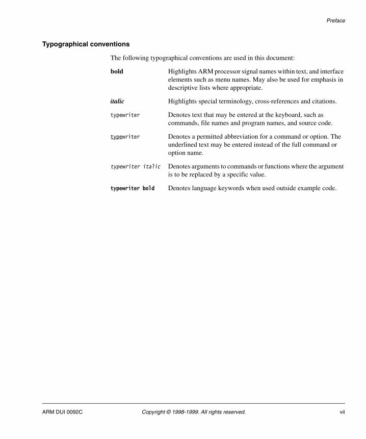
Typographical conventions
The following typographical conventions are used in this document:
bold Highlights ARM processor signal names within text, and interface elements such as menu names. May also be used for emphasis in descriptive lists where appropriate.
italic Highlights special terminology, cross-references and citations.
typewriter Denotes text that may be entered at the keyboard, such as commands, file names and program names, and source code.
typewriter Denotes a permitted abbreviation for a command or option. The underlined text may be entered instead of the full command or option name.
typewriter italic Denotes arguments to commands or functions where the argument is to be replaced by a specific value.
typewriter bold Denotes language keywords when used outside example code.
ARM DUI 0092C Copyright © 1998-1999. All rights reserved. vii
Preface
Further reading
This section lists publications by ARM Limited.
ARM publications
AHB Example AMBA SYstem Technical Reference Manual (ARM DDI 0170).
ASB Example AMBA SYstem (Micropack v1.3) Technical Reference Manual (ARM DDI 0138).
ARM7TDMI Data Sheet (ARM DDI 0029).
AMBA Specification Rev 2.0 (ARM IHI 0011).
Reference Peripherals Specification (ARM DDI 0062).
viii Copyright © 1998-1999. All rights reserved. ARM DUI 0092C
Preface
Feedback
ARM Limited welcomes feedback both on the Example AMBA SYstem, and on the documentation.
Feedback on this document
If you have any comments on about this document, please send email to [email protected] giving:
• the document title
• the document number
• the page number(s) to which your comments refer
• a concise explanation of your comments.
General suggestions for additions and improvements are also welcome.
Feedback on the Example AMBA SYstem
If you have any comments or suggestions about this product, please contact your supplier giving:
• the product name
• a concise explanation of your comments.
ARM DUI 0092C Copyright © 1998-1999. All rights reserved. ix
Preface
x Copyright © 1998-1999. All rights reserved. ARM DUI 0092C

Chapter 1 Introduction
This chapter provides an introduction to the EASY system. The chapter gives information about the overall structure and individual modules that constitute the EASY system:
• ASB-based EASY systems on page 1-2
• Structure of the EASY system on page 1-3
• General system structure on page 1-6.
ARM DUI 0092C Copyright © 1998-1999. All rights reserved. 1-1
Introduction
1.1 ASB-based EASY systems
While this manual does contain some information about ASB-based EASY systems it is primarily aimed at users of AHB-based EASY systems. Readers who want to design ASB-based EASY systems should refer to the following manuals:
• Example AMBA SYstem (Micropack v1.3) User Guide
• Example AMBA SYstem (Micropack v1.3) Technical Reference Manual.
1-2 Copyright © 1998-1999. All rights reserved. ARM DUI 0092C
Introduction
1.2 Structure of the EASY system
The EASY microcontroller comprises the building blocks needed to create an example system based on the low-power, generic design methodology of the Advanced Microcontroller Bus Architecture (AMBA).
The EASY microcontroller:
• enables custom devices to be developed in very short design cycles
• allows the resulting sub-components to be re-used easily in future designs.
1.2.1 EASY system blocks
The example design provides all the system modules needed to manage an AMBA system:
• reset controller
• arbiter
• decoder.
These system modules control the various aspects of the main system bus (either AHB or ASB).
1.2.2 EASY components
The example design contains:
• Two bus masters:
— the ARM processor to allow execution of the ARM code
— the Test Interface Controller (TIC), to allow external control of the system bus during system test.
• A minimum set of basic microcontroller peripherals which are implemented as low-power designs on the AMBA Advanced Peripheral Bus (APB), including:
— an interrupt controller
— a remap and pause controller
— a 16-bit timer module.
• The example Static Memory Interface (SMI). This demonstrates the minimum requirements for an External Bus Interface (EBI).
• A 1KB block of internal memory.
ARM DUI 0092C Copyright © 1998-1999. All rights reserved. 1-3
Introduction
Note The ARM processor module is only a model used for simulation and testing of the system.
Figure 1-5 on page 1-10 illustrates the structure of the AHB system. Figure 1-6 on page 1-10 illustrates the structure of the ASB system.
Note The processor module is not synthesizable in its entirety. This document does not tell you how to integrate the ARM processor macrocell into the synthesizable AMBA bus master logic veneer. See the documentation for the chosen ARM processor core type for further information.
1.2.3 AMBA bus master logic
You can connect the EASY microcontroller to any ARM processor core or cached macrocell. However, different processors require different AMBA bus master logic to control them.
Many ARM processor cached macrocells are supplied with an AMBA interface. However, the ARM7TDMI requires the AMBA wrapper supplied with the example system.
The AMBA ARM7TDMI bus master wrapper with test supports debug, using:
• COMMTX and COMMRX (connected internally in EASY)
• the JTAG pins for debug communications (not serial test or board level test).
For more information refer to the Example AMBA System Micropack v2.0 Technical Reference Manual.
For further information on variants, please contact ARM Limited.
1.2.4 Standard EASY component modifications
A typical design flow using EASY requires replacement or removal of the following components:
SMI Replace with system-specific memory controllers and an EBI.
Internal memory Remove or replace with a real SRAM component.
1-4 Copyright © 1998-1999. All rights reserved. ARM DUI 0092C
Introduction
Provision is also made for the optional addition of:
• APB low-power peripherals, such as a UART or parallel port
• AHB or ASB slaves, such as a PC card (PCMCIA) interface or video controller
• AHB or ASB masters, such as a DMA engine or graphics processor.
These additions require minor modifications to the AMBA decoder, arbiter, or APB bridge interface, where appropriate. The Example AMBA System Technical Reference Manual contains details of all modules in the system, and describes the modifications required in each case.
Note If you are using EASY as the basis for new microcontroller designs, ensure that your designs conform fully to the AMBA Specification, the Reference Peripherals Specification, and the base block designs of those presented in the EASY microcontroller. If you make minor changes to bus or state machine operation, you may produce a design that does not allow the ease of re-use, modification, or addition provided by the AMBA Specification.
ARM DUI 0092C Copyright © 1998-1999. All rights reserved. 1-5
Introduction
1.3 General system structure
There are three main structures associated with the EASY system:
• The file structure
• The system hierarchy on page 1-9
• The system connection layout on page 1-10.
1.3.1 The file structure
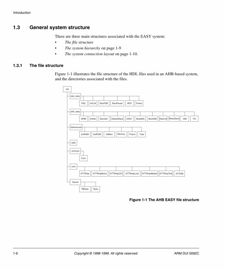
Figure 1-1 illustrates the file structure of the HDL files used in an AHB-based system, and the directories associated with the files.
Figure 1-1 The AHB EASY file structure
hdl
apb_easy
ahb_easy
cells
common
EASY SMI
Conv
APBif Arbiter Decoder
FRC IntCntl
IntMem
RemPause
ResCntl
RPS
TIC
Timers
ExtRAM ExtROM Memory
TBEasy TBTic
Ticbox
behavioural
A7TWrap A7TWrapMasterA7TWrapBurst A7TWrapTestA7TWrapCtrl A7TDMIA7TWrapLock
core
tbench
MuxP2B
MuxM2S MuxS2M RetrySlave
Tube
DefaultSlave
1-6 Copyright © 1998-1999. All rights reserved. ARM DUI 0092C

Introduction
Figure 1-2 illustrates the file structure of the HDL files used in an ASB-based system, and the directories associated with the files.
Figure 1-2 The ASB EASY file structure
At the top level of the file structure of both Figure 1-1 on page 1-6 and Figure 1-2 is the HDL directory. This directory is either vhdl or verilog depending on the chosen language. The directory contains seven sub-directories:
• apb_easy contains the standard APB peripherals and the RPS top-level structural file.
• asb_easy/ahb_easy contains all standard synthesizable modules connected to the system bus:
— APB bridge
— arbiter
— decoder
— top-level EASY structural file
— pll (clock generator) (asb_easy only)
hdl
apb_easy
asb_easy
cells
common
EASY PLL SMI
Defs Conv
APBif Arbiter
BusWatch
Decoder
FRC IntCntl
IntMem
RemPause
ResCntl
RPS
TIC
Timers
ExtRAM ExtROM Memory
TBEasy TBTic
Ticbox
behavioural
A7TWrap A7TWrapTestA7TWrapCtrl A7TWrapTriA7TWrapDbus A7TDMIA7TWrapMSM
core
tbench
ARM DUI 0092C Copyright © 1998-1999. All rights reserved. 1-7
Introduction
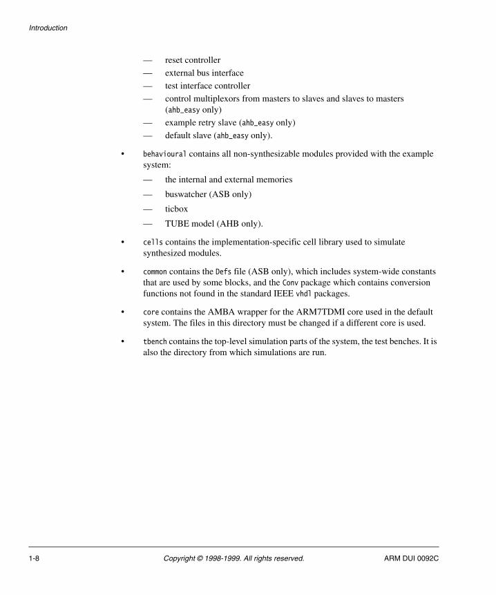
— reset controller
— external bus interface
— test interface controller
— control multiplexors from masters to slaves and slaves to masters (ahb_easy only)
— example retry slave (ahb_easy only)
— default slave (ahb_easy only).
• behavioural contains all non-synthesizable modules provided with the example system:
— the internal and external memories
— buswatcher (ASB only)
— ticbox
— TUBE model (AHB only).
• cells contains the implementation-specific cell library used to simulate synthesized modules.
• common contains the Defs file (ASB only), which includes system-wide constants that are used by some blocks, and the Conv package which contains conversion functions not found in the standard IEEE vhdl packages.
• core contains the AMBA wrapper for the ARM7TDMI core used in the default system. The files in this directory must be changed if a different core is used.
• tbench contains the top-level simulation parts of the system, the test benches. It is also the directory from which simulations are run.
1-8 Copyright © 1998-1999. All rights reserved. ARM DUI 0092C
Introduction
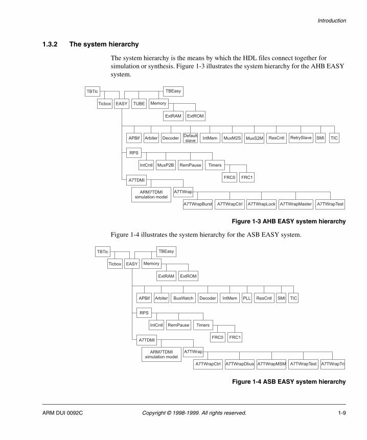
1.3.2 The system hierarchy
The system hierarchy is the means by which the HDL files connect together for simulation or synthesis. Figure 1-3 illustrates the system hierarchy for the AHB EASY system.
Figure 1-3 AHB EASY system hierarchy
Figure 1-4 illustrates the system hierarchy for the ASB EASY system.
Figure 1-4 ASB EASY system hierarchy
APBif Arbiter Decoder
FRC0
IntCntl
IntMem
RemPause
ResCntl TIC
A7TWrap
A7TWrapMasterA7TWrapBurst A7TWrapTestA7TWrapCtrl A7TWrapLock
ExtRAM ExtROM
ARM7TDMIsimulation model
FRC1
RPS
Timers
A7TDMI
TBTic
Ticbox
TBEasy
MemoryEASY
SMI
TUBE
MuxM2S MuxS2M RetrySlave
MuxP2B
Defaultslave
APBif Arbiter BusWatch Decoder
FRC0
IntCntl
IntMem
RemPause
ResCntl TIC
A7TWrap
A7TWrapTestA7TWrapCtrl A7TWrapTriA7TWrapDbus A7TWrapMSM
ExtRAM ExtROM
ARM7TDMIsimulation model
FRC1
RPS
Timers
A7TDMI
TBTic
Ticbox
TBEasy
MemoryEASY
PLL SMI
ARM DUI 0092C Copyright © 1998-1999. All rights reserved. 1-9
Introduction
The system hierarchy is the structure present in an HDL simulation of the EASY system, with the TBTic or TBEasy test bench at the top, and all other modules instantiated from it.
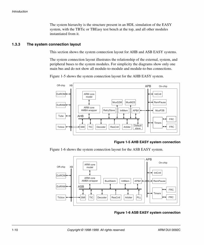
1.3.3 The system connection layout
This section shows the system connection layout for AHB and ASB EASY systems.
The system connection layout illustrates the relationship of the external, system, and peripheral buses to the system modules. For simplicity the diagrams show only one main bus and do not show all module-to-module and module-to-bus connections.
Figure 1-5 shows the system connection layout for the AHB EASY system.
Figure 1-5 AHB EASY system connection
Figure 1-6 shows the system connection layout for the ASB EASY system.
Figure 1-6 ASB EASY system connection
AHB
APBXB
RetrySlave
ARM coremodel
ExtROM
ExtRAM
Ticbox TICSMI Arbiter
IntMem
ResCntlDecoder
APBif
ARM coreAMBA wrapper
IntCntl
RemPause
Timers
Off-chip On-chip
FRC
FRC
MuxP2B
MuxS2M MuxM2S
Tube
Defaultslave
ASB
APB
XB
BusWatch
ARM coremodel
ExtROM
ExtRAM
Ticbox TICSMI Arbiter
IntMem
ResCntlDecoder PLL
APBif
ARM coreAMBA wrapper
IntCntl
RemPause
Off-chip
On-chip
Timers
FRC
FRC
1-10 Copyright © 1998-1999. All rights reserved. ARM DUI 0092C
Chapter 2 Initialization
This chapter provides information on how to initialize the EASY System in the following section:
• System setup on page 2-2.
ARM DUI 0092C Copyright © 1998-1999. All rights reserved. 2-1
Initialization
2.1 System setup
Initialization consists of copying the EASY system files from the CD supplied. The following restrictions should be applied:
1. Use the default directory setup for your directory structure.
2. Do not set up symbolic links.
3. Do not make environment settings.
Once this procedure has been completed you are ready to install, set up and run a simulation as described in Chapter 3 Simulation.
2-2 Copyright © 1998-1999. All rights reserved. ARM DUI 0092C
Chapter 3 Simulation
This chapter provides information on the two simulations that you can run on the EASY system:
• TICTalk testing using the TBTic test bench
• ARM software test using the TBEasy test bench.
The main parts of the system are the same for both simulations, but the actual stimulus and input files are different. The following sections describe the simulation processes:
• Simulation setup on page 3-2
• System compilation on page 3-3
• TBTic test bench on page 3-5
• TBEasy test bench on page 3-8
• Simulation messages on page 3-11
• Test programs on page 3-14
• Setup to simulate a synthesized EASY system on page 3-18.
ARM DUI 0092C Copyright © 1998-1999. All rights reserved. 3-1
Simulation
3.1 Simulation setup
When you have copied the system files as described in Chapter 2 Initialization, the EASY system is ready for use with a simulation tool.
If you are using an ARM core, install and set up a simulation model of the required type for the specific simulator and operating system. Refer to the documentation provided with the model for information about how to install and use the model.
3-2 Copyright © 1998-1999. All rights reserved. ARM DUI 0092C
Simulation
3.2 System compilation
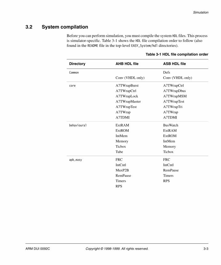
Before you can perform simulation, you must compile the system HDL files. This process is simulator-specific. Table 3-1 shows the HDL file compilation order to follow (also found in the README file in the top-level EASY_System/hdl directories).
Table 3-1 HDL file compilation order
Directory AHB HDL file ASB HDL file
Common
Conv (VHDL only)
Defs
Conv (VHDL only)
core A7TWrapBurst
A7TWrapCtrl
A7TWrapLock
A7TWrapMaster
A7TWrapTest
A7TWrap
A7TDMI
A7TWrapCtrl
A7TWrapDbus
A7TWrapMSM
A7TWrapTest
A7TWrapTri
A7TWrap
A7TDMI
behavioural ExtRAM
ExtROM
IntMem
Memory
Ticbox
Tube
BusWatch
ExtRAM
ExtROM
IntMem
Memory
Ticbox
apb_easy FRC
IntCntl
MuxP2B
RemPause
Timers
RPS
FRC
IntCntl
RemPause
Timers
RPS
ARM DUI 0092C Copyright © 1998-1999. All rights reserved. 3-3
Simulation
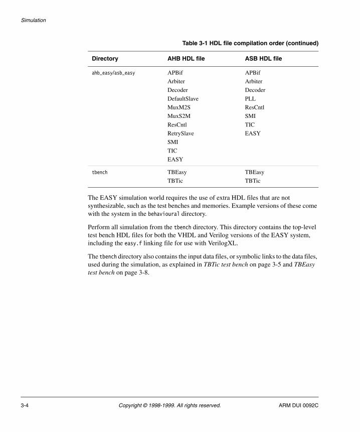
The EASY simulation world requires the use of extra HDL files that are not synthesizable, such as the test benches and memories. Example versions of these come with the system in the behavioural directory.
Perform all simulation from the tbench directory. This directory contains the top-level test bench HDL files for both the VHDL and Verilog versions of the EASY system, including the easy.f linking file for use with VerilogXL.
The tbench directory also contains the input data files, or symbolic links to the data files, used during the simulation, as explained in TBTic test bench on page 3-5 and TBEasy test bench on page 3-8.
ahb_easy/asb_easy APBif
Arbiter
Decoder
DefaultSlave
MuxM2S
MuxS2M
ResCntl
RetrySlave
SMI
TIC
EASY
APBif
Arbiter
Decoder
PLL
ResCntl
SMI
TIC
EASY
tbench TBEasy
TBTic
TBEasy
TBTic
Table 3-1 HDL file compilation order (continued)
Directory AHB HDL file ASB HDL file
3-4 Copyright © 1998-1999. All rights reserved. ARM DUI 0092C

Simulation
3.3 TBTic test bench
The TBTic test bench uses the ticbox to drive the Test Interface Controller (TIC) to apply test vectors to the EASY components. Figure 3-1 shows the basic layout of the TBTic system.
Figure 3-1 Block diagram of TBTic
3.3.1 Setting the TBTic clock frequency
To alter the clock frequency used in the TBTic test bench, change the delay mechanism in the reset and clock generation control module. The default is a 40ns period, or 25MHz for the ASB system and a 20ns period, or 50MHz for the AHB system. A 40MHz clock requires the use of an ASB decoder with wait states. When the clock frequency is 33MHz or less, you can use an ASB decoder without wait states.
At the start of the system operation, the system reset signal that is fed to the reset and clock generation control module is generated based on set numbers of clock cycles for its high and low phases.
3.3.2 Inputting data to the TBTic test bench
The TIC Interface Format (TIF) file contains the test-pattern commands.
The TICBOX reads the TIF file and translates the test-pattern commands into their respective TIC signal sequences. The TIC signal sequences are then applied to the EASY components.
EASYReset and clockgeneration control
TICBOX:Test pattern file processor and TestInterface Controller driver
TBTic
ARM DUI 0092C Copyright © 1998-1999. All rights reserved. 3-5
Simulation
The TIC signals control the system:
• reads
• writes
• address changes.
These commands are taken from the input file and displayed in the simulation window. An example of this for VHDL is shown in Example 3-1 on page 3-7 (the Verilog trace shows similar transfer type information).
The HDL version of the EASY system you are running determines the type of input files used to input data to the test bench.
VHDL
When you are using a VHDL version of the TBTic test bench, the data comes from infile.tif file in the tbench directory. The infile.tif file is a TIF file that is generated from TICTalk test patterns found in the EASY_System/tictests directory. (You can find precompiled TIF files for the APB peripherals in the tictests/invec directory.) The infile.tif can be one of the following:
• a copy of a compiled TIF file
• a symbolic link to a TIF file in the invec directory.
For more information on the file formats, conversion processes, and generation of new test vector files, consult the Test Interface Driver section of the Example AMBA System (Micropack v2.0) Technical Reference Manual.
Note Messages starting with a semi-colon (;) are comments from the TIF file broadcast by the TICBOX.
The warnings shown in Example 3-1 on page 3-7 indicate that the test on the read value has failed. You can modify the TICBOX to generate Failure assertions when test errors are detected. See the Example AMBA System Technical Reference Manual, Chapter 5 Test interface driver, for more details about read vector assertions. When the test is complete, TBTic halts the simulation with a Failure assertion.
The system applies the read vectors in a pipelined fashion, so the value read back from a read vector is checked several cycles after the Reading :Expected... message.
3-6 Copyright © 1998-1999. All rights reserved. ARM DUI 0092C
Simulation
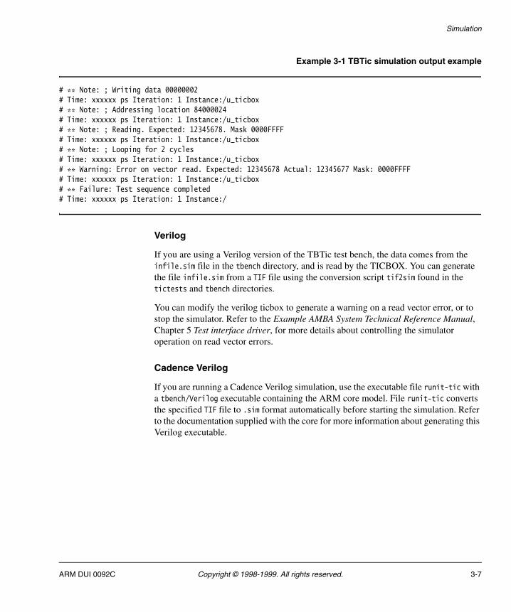
Example 3-1 TBTic simulation output example
# ** Note: ; Writing data 00000002# Time: xxxxxx ps Iteration: 1 Instance:/u_ticbox# ** Note: ; Addressing location 84000024# Time: xxxxxx ps Iteration: 1 Instance:/u_ticbox# ** Note: ; Reading. Expected: 12345678. Mask 0000FFFF# Time: xxxxxx ps Iteration: 1 Instance:/u_ticbox# ** Note: ; Looping for 2 cycles# Time: xxxxxx ps Iteration: 1 Instance:/u_ticbox# ** Warning: Error on vector read. Expected: 12345678 Actual: 12345677 Mask: 0000FFFF# Time: xxxxxx ps Iteration: 1 Instance:/u_ticbox# ** Failure: Test sequence completed# Time: xxxxxx ps Iteration: 1 Instance:/
Verilog
If you are using a Verilog version of the TBTic test bench, the data comes from the infile.sim file in the tbench directory, and is read by the TICBOX. You can generate the file infile.sim from a TIF file using the conversion script tif2sim found in the tictests and tbench directories.
You can modify the verilog ticbox to generate a warning on a read vector error, or to stop the simulator. Refer to the Example AMBA System Technical Reference Manual, Chapter 5 Test interface driver, for more details about controlling the simulator operation on read vector errors.
Cadence Verilog
If you are running a Cadence Verilog simulation, use the executable file runit-tic with a tbench/Verilog executable containing the ARM core model. File runit-tic converts the specified TIF file to .sim format automatically before starting the simulation. Refer to the documentation supplied with the core for more information about generating this Verilog executable.
ARM DUI 0092C Copyright © 1998-1999. All rights reserved. 3-7
Simulation
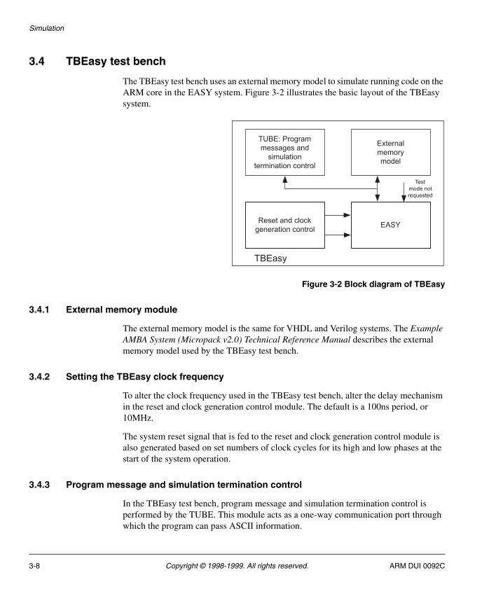
3.4 TBEasy test bench
The TBEasy test bench uses an external memory model to simulate running code on the ARM core in the EASY system. Figure 3-2 illustrates the basic layout of the TBEasy system.
Figure 3-2 Block diagram of TBEasy
3.4.1 External memory module
The external memory model is the same for VHDL and Verilog systems. The Example AMBA System (Micropack v2.0) Technical Reference Manual describes the external memory model used by the TBEasy test bench.
3.4.2 Setting the TBEasy clock frequency
To alter the clock frequency used in the TBEasy test bench, alter the delay mechanism in the reset and clock generation control module. The default is a 100ns period, or 10MHz.
The system reset signal that is fed to the reset and clock generation control module is also generated based on set numbers of clock cycles for its high and low phases at the start of the system operation.
3.4.3 Program message and simulation termination control
In the TBEasy test bench, program message and simulation termination control is performed by the TUBE. This module acts as a one-way communication port through which the program can pass ASCII information.
EASY
External
memory
model
TUBE: Program
messages and
simulation
termination control
Reset and clock
generation control
Test
mode not
requested
TBEasy
3-8 Copyright © 1998-1999. All rights reserved. ARM DUI 0092C

Simulation
Messages are written, one byte at a time, to location 0x20000000 in external memory. This location is used by the TUBE model, which buffers received bytes until a terminating control character is recognized and the message is printed by the simulator, for example:
# ** Note: TUBE: Hard Reset# Time: xxxxxxx ps Iteration: 0 Instance:/
In this example the message Hard Reset has been passed to the TUBE. The program running on the microcontroller can also terminate simulation by writing a control character to the TUBE with no message to produce the following assertion:
# ** Failure: TUBE: Program exit# Time: xxxxxxx ps Iteration: 0 Instance:/
The control codes passed to the TUBE are also output to the file tbench/tube.
3.4.4 Inputting data to the TBEasy test bench
The input data required to run the simulation comes from the four memory data files, rom0.dat to rom3.dat, that are located in the tbench directory. The external ROM models load the memory data files. The ARM core reads the data from ROM when the simulation is running.
The following sections describe the process:
• Creating memory data files
• Reducing simulation runtimes
• Cadence simulation on page 3-10.
Creating memory data files
The format of the memory data files is the same for both VHDL and Verilog memory models. The original code is compiled in the EASY_System/code directory.
To create the memory data files:
1. Write the necessary files in either C or ARM assembly language.
2. Compile and convert the source files into rom(n).dat files.
Test programs on page 3-14 describes this complete process in more detail.
Reducing simulation runtimes
You can reduce the simulation runtime by loading the internal memory or external SRAM models with data. This enables access to user data during the execution of programs, avoiding the use of test programs for manual data storage.
ARM DUI 0092C Copyright © 1998-1999. All rights reserved. 3-9
Simulation
The tbench/intram.dat file is loaded by the 1KB internal memory, and must contain data in 8-character hexadecimal $readmemh Verilog format (for both the VHDL and Verilog format models).
Note Loading takes place with or without addresses. When no addresses are used, loading starts from 0.
If you want to load the external SRAM with data you must use ram.dat files that have the same format as the rom.dat files for the external ROM models.
Cadence simulation
To input data to the TBEasy test bench for a Cadence simulation, use the runit-easy executable with a tbench/verilog simulator executable containing the model of the ARM core.
3-10 Copyright © 1998-1999. All rights reserved. ARM DUI 0092C
Simulation
3.5 Simulation messages
During simulation, some of the non-synthesizable models generate messages in the simulation window. These simulation messages show either that the simulation is proceeding as normal, or that there is an error in the system.
This section details most of the possible messages that can be generated during a simulation run. These include:
• Startup messages
• ARM core messages on page 3-12
• Buswatcher messages (ASB only) on page 3-12
• TICTalk messages on page 3-13
• Netlist messages on page 3-13
• Other messages on page 3-13.
Note The examples given are for the Modeltech VSIM simulator running a VHDL EASY model. Other simulators may produce slightly different message formats.
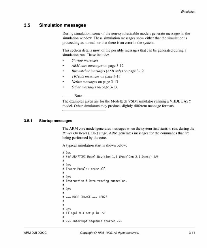
3.5.1 Startup messages
The ARM core model generates messages when the system first starts to run, during the Power On Reset (POR) stage. ARM generates messages for the commands that are being performed by the core.
A typical simulation start is shown below:
# 0ps# ### ARM7TDMI Model Revision 1.4 (ModelGen 2.1.0beta) ##### 0ps# Tracer Module: trace all## 0ps# Instruction & Data tracing turned on.## 0ps## === MODE CHANGE ==> USR26### 0ps# Illegal MUX setup in PSR## >>> Interrupt sequence started <<<
ARM DUI 0092C Copyright © 1998-1999. All rights reserved. 3-11
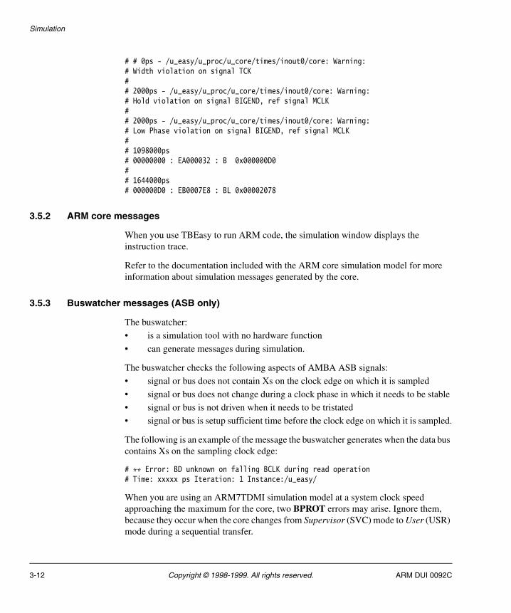
Simulation
# # 0ps - /u_easy/u_proc/u_core/times/inout0/core: Warning:# Width violation on signal TCK## 2000ps - /u_easy/u_proc/u_core/times/inout0/core: Warning:# Hold violation on signal BIGEND, ref signal MCLK## 2000ps - /u_easy/u_proc/u_core/times/inout0/core: Warning:# Low Phase violation on signal BIGEND, ref signal MCLK## 1098000ps# 00000000 : EA000032 : B 0x000000D0## 1644000ps# 000000D0 : EB0007E8 : BL 0x00002078
3.5.2 ARM core messages
When you use TBEasy to run ARM code, the simulation window displays the instruction trace.
Refer to the documentation included with the ARM core simulation model for more information about simulation messages generated by the core.
3.5.3 Buswatcher messages (ASB only)
The buswatcher:
• is a simulation tool with no hardware function
• can generate messages during simulation.
The buswatcher checks the following aspects of AMBA ASB signals:
• signal or bus does not contain Xs on the clock edge on which it is sampled
• signal or bus does not change during a clock phase in which it needs to be stable
• signal or bus is not driven when it needs to be tristated
• signal or bus is setup sufficient time before the clock edge on which it is sampled.
The following is an example of the message the buswatcher generates when the data bus contains Xs on the sampling clock edge:
# ** Error: BD unknown on falling BCLK during read operation# Time: xxxxx ps Iteration: 1 Instance:/u_easy/
When you are using an ARM7TDMI simulation model at a system clock speed approaching the maximum for the core, two BPROT errors may arise. Ignore them, because they occur when the core changes from Supervisor (SVC) mode to User (USR) mode during a sequential transfer.
3-12 Copyright © 1998-1999. All rights reserved. ARM DUI 0092C

Simulation
3.5.4 TICTalk messages
When a TICTalk test is being run, it displays each TIC command. Bear in mind that TIC commands correspond to combinations of TIC signals. When the read data is incorrect, it gives rise to an error message.
3.5.5 Netlist messages
When you are simulating netlist files, timing differences from the original behavioral HDL, or incorrect setup times on register cells, may generate extra messages.
3.5.6 Other messages
If you receive any other messages that are not described in this section, or are not from the ARM core simulation model and are not standard simulator messages, use the following to help you track down their cause:
• the assertion time
• simulation waveform display
• the ARM instruction trace.
ARM DUI 0092C Copyright © 1998-1999. All rights reserved. 3-13
Simulation
3.6 Test programs
The default system contains two example test programs that you can run on the system to generate ARM-based code:
easy_c.c C test program, found in EASY_System/code/easy_c
easy_asm.s an ARM assembly language test program, found in EASY_System/code/easy_asm.
3.6.1 easy_c.c
The easy_c.c example C program is compiled with the embedded C library using the armcc compiler from the ARM Software Development Toolkit.
This program:
• exercises the basic RPS functions
• checks the operation of the counters
• reports the results of the checks using the TUBE.
The advantages of using C rather than an assembly language test program are that:
• you do not have to be familiar with ARM assembly language
• C is a high-level programming language.
The disadvantage of using C is that you cannot directly control the ARM instruction sequence produced by the compiler.
When you use easy_c.c under simulation, it is quite difficult to establish which section of the C program is currently executing by looking at the instruction trace. You can use the TUBE program to output messages during simulation to avoid this problem.
The easy_c.c test program is described in:
• Compiling and converting easy_c.c
• Files used by easy_c.c on page 3-15
• Components not tested when using easy_c.c on page 3-15
• easy_c.c test program messages on page 3-15.
Compiling and converting easy_c.c
To use easy_c.c with the external ROM model in the EASY system, you must compile the test and convert it into a memory file format (.dat). To do this, use the makefile supplied and type make.
The ARM Software Development Toolkit commands armcc, armasm, and armlink must be available in your path for use.
3-14 Copyright © 1998-1999. All rights reserved. ARM DUI 0092C
Simulation
Files used by easy_c.c
During compilation the easy_c.c test program uses the following files:
• easy_c.c
• init.s
• irq.s
• support.c
• reset.s
• easy_init.s
• arm.h
• peripherals.h
The EASY_System/code {easy_c, common, include} directories hold these files. For details refer to the README file in the code/easy_c directory.
Components not tested when using easy_c.c
Although the easy_c.c program and the tests it performs are quite basic, running the program on the EASY microcontroller model exercises most components within the system. The only sections that are not well exercised by these tests are the:
• test veneers
• Test Interface Controller (TIC)
• arbiter (though this is exercised partially by the reset and pause sequences).
easy_c.c test program messages
In normal execution on the EASY microcontroller, the test program sends the following messages via the TUBE. The messages, and the related conditions and events that initiate the messages, are tabulated below:
Easy C test: Initial message.
Power on reset This message is sent if the Power On Reset (POR) condition is detected in the reset status register of the remap and pause controller. The message Soft Reset is sent if the condition is not detected.
Display ID Reads ID information from the remap and pause controller.
ARM DUI 0092C Copyright © 1998-1999. All rights reserved. 3-15
Simulation
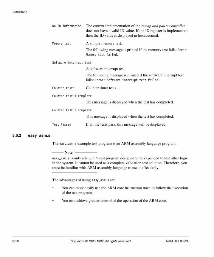
No ID information The current implementation of the remap and pause controller does not have a valid ID value. If the ID register is implemented then the ID value is displayed in hexadecimal.
Memory test A simple memory test.
The following message is printed if the memory test fails: Error: Memory test failed.
Software interrupt test
A software interrupt test.
The following message is printed if the software interrupt test fails: Error: Software interrupt test failed.
Counter tests Counter timer tests.
Counter test 1 complete
This message is displayed when the test has completed.
Counter test 2 complete
This message is displayed when the test has completed.
Test Passed If all the tests pass, this message will be displayed.
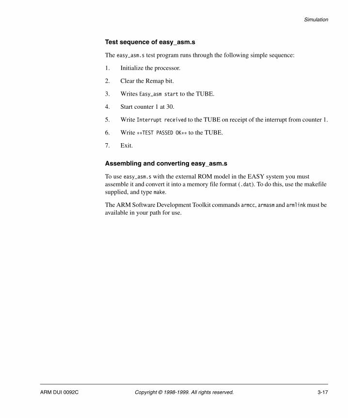
3.6.2 easy_asm.s
The easy_asm.s example test program is an ARM assembly language program.
Note easy_asm.s is only a template test program designed to be expanded to test other logic in the system. It cannot be used as a complete validation test solution. Therefore, you must be familiar with ARM assembly language to use it effectively.
The advantages of using easy_asm.s are:
• You can more easily use the ARM core instruction trace to follow the execution of the test program.
• You can achieve greater control of the operation of the ARM core.
3-16 Copyright © 1998-1999. All rights reserved. ARM DUI 0092C
Simulation
Test sequence of easy_asm.s
The easy_asm.s test program runs through the following simple sequence:
1. Initialize the processor.
2. Clear the Remap bit.
3. Writes Easy_asm start to the TUBE.
4. Start counter 1 at 30.
5. Write Interrupt received to the TUBE on receipt of the interrupt from counter 1.
6. Write **TEST PASSED OK** to the TUBE.
7. Exit.
Assembling and converting easy_asm.s
To use easy_asm.s with the external ROM model in the EASY system you must assemble it and convert it into a memory file format (.dat). To do this, use the makefile supplied, and type make.
The ARM Software Development Toolkit commands armcc, armasm and armlink must be available in your path for use.
ARM DUI 0092C Copyright © 1998-1999. All rights reserved. 3-17
Simulation
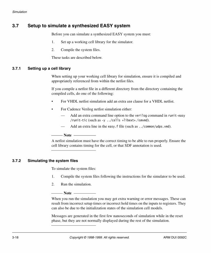
3.7 Setup to simulate a synthesized EASY system
Before you can simulate a synthesized EASY system you must:
1. Set up a working cell library for the simulator.
2. Compile the system files.
These tasks are described below.
3.7.1 Setting up a cell library
When setting up your working cell library for simulation, ensure it is compiled and appropriately referenced from within the netlist files.
If you compile a netlist file in a different directory from the directory containing the compiled cells, do one of the following:
• For VHDL netlist simulation add an extra use clause for a VHDL netlist.
• For Cadence Verilog netlist simulation either:
— Add an extra command line option to the verilog command in runit-easy /runit-tic (such as -y ../cells +libext+.ismvmd).
— Add an extra line in the easy.f file (such as ../common/udps.vmd).
Note A netlist simulation must have the correct timing to be able to run properly. Ensure the cell library contains timing for the cell, or that SDF annotation is used.
3.7.2 Simulating the system files
To simulate the system files:
1. Compile the system files following the instructions for the simulator to be used.
2. Run the simulation.
Note When you run the simulation you may get extra warning or error messages. These can result from incorrect setup times or incorrect hold times on the inputs to registers. They can also be due to the initialization states of the simulation cell models.
Messages are generated in the first few nanoseconds of simulation while in the reset phase, but they are not normally displayed during the rest of the simulation.
3-18 Copyright © 1998-1999. All rights reserved. ARM DUI 0092C

Chapter 4 ASB Synthesis
This chapter explains how to synthesize the ASB EASY system using the Synopsys synthesis tool with the script files supplied. It contains the following sections:
• Synthesizing the EASY system on page 4-2
• EASY synthesis process on page 4-3
• Synthesizing new ASB modules on page 4-7.
ARM DUI 0092C Copyright © 1998-1999. All rights reserved. 4-1
ASB Synthesis
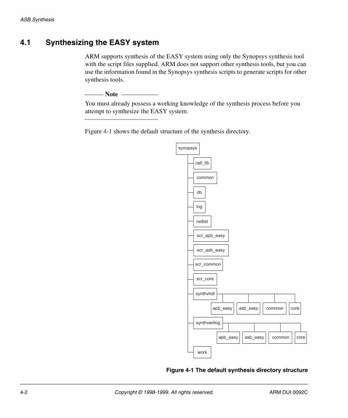
4.1 Synthesizing the EASY system
ARM supports synthesis of the EASY system using only the Synopsys synthesis tool with the script files supplied. ARM does not support other synthesis tools, but you can use the information found in the Synopsys synthesis scripts to generate scripts for other synthesis tools.
Note You must already possess a working knowledge of the synthesis process before you attempt to synthesize the EASY system.
Figure 4-1 shows the default structure of the synthesis directory.
Figure 4-1 The default synthesis directory structure
synopsys
cell_lib
synthvhdl
apb_easy asb_easy common core
work
netlist
synthverilog
scr_asb_easy
scr_apb_easy
common
scr_common
scr_core
db
log
apb_easy asb_easy common core
4-2 Copyright © 1998-1999. All rights reserved. ARM DUI 0092C
ASB Synthesis
4.2 EASY synthesis process
The following subsections describe facets of the EASY synthesis process:
• Requirements for the default EASY system for synthesis
• Purpose of synthesis scripts
• ASB synthesis scripts on page 4-4.
4.2.1 Requirements for the default EASY system for synthesis
The system must have access to the standard Synopsys synthesis tools version 1998.02 or later. To meet this prerequisite, carry out the following checks and modifications:
1. Ensure that the system directory structure is the same as in the EASY_System directory so that the synthesis script files can find the correct HDL source files.
2. Ensure that a Synopsys format .db cell library is available from the synopsys/cell_lib directory.
3. Update the library name and search path and choose the HDL type in the scr_common/setup.scr file.
4. Change the environmental constraints in the scr_common/global.scr file:
• change the wire load from ForQA to an acceptable load in the Operating Conditions section
• replace the d-type driving cell, q1dffd1, with your library equivalent
• replace the inverter input pin load, q1invd0/i, with your library equivalent.
When the system is set up correctly, you can synthesize the EASY modules.
4.2.2 Purpose of synthesis scripts
The standard synthesis process needs a script to:
• read in the HDL behavioral source file
• set up the general system parameters
• constrain the port timing
• synthesize the module
• generate reports for the timing, area and cells used
• write the netlist files in Synopsys format and HDL netlist format for use in simulation.
ARM DUI 0092C Copyright © 1998-1999. All rights reserved. 4-3
ASB Synthesis
Use the supplied synthesis scripts in the synopsys/scr_* directories, to carry out the standard synthesis process.
4.2.3 ASB synthesis scripts
There are five main synthesis scripts that are used by each module in the ASB EASY system:
<module>.cmd The synthesis command file contains the dc_shell command list used to synthesize the module.
<module>.scr The synthesis constraints file contains the timing constraints for the module input and output ports that are not included in the standard .scr files.
apb_slave.scr, asb_master.scr, asb_slave.scr
These contain generic port timing information for the standard APB and ASB signals (such as BD, PRDATA) for APB peripherals, and ASB masters and slaves.
global.scr The global file sets up the system clock parameters (default 40MHz = 25ns clock), ARM7TDMI wrapper output timings on the ASB signals, and sets the general system operating conditions.
setup.scr The setup file configures the cell libraries used by the system (current default is q1cells), HDL to synthesize to (default is vhdl), and other standard dc_shell settings.
Additional shell scripts, namely the run_hdl_bus_module files found in the synopsys directory, exist to start the synthesis process. These scripts:
• copy the chosen HDL source file from the ../hdl directory into the synthhdl directory
• start dc_shell with the module.cmd synthesis script
• pipe the output command log into the file log/module_hdl.log.
File conversion
Some VHDL source files use the conversion program hhd2synth to make them compatible for synthesis.
The conversion:
• removes any after statements that are in the code
4-4 Copyright © 1998-1999. All rights reserved. ARM DUI 0092C
ASB Synthesis
• changes rising_edge to CLK’ event and CLK = 1 for compatibility with Synopsys versions previous to 1998.02
• performs other processing as described in the synopsys/vhd2synth.txt file.
Note The vhd2synth conversion program writes output files only with lowercase filenames. Because the <module>.cmd files supplied expect mixed-case VHDL filenames, the converted VHDL files must be renamed to their original mixed-case format. This renaming is done to the ARM7TDMI core wrapper files that require conversion only by the run_vhdl_A7Wrap script.
Run script files
There is a run_hdl_bus_module file for each synthesizable module of the standard EASY system.
The combined script run_hdl_asb_ALL:
• calls the other run_hdl_bus_module scripts for the same hdl
• creates the two extra log files named errors_hdl.txt and violated_hdl.txt.
The run_hdl_asb_ALL script generates the extra log files using grep to find the words Error and VIOLATED in the module_hdl.log files. Each of these words indicates a problem with the synthesis process. Violated_hdl.txt always contains at least one line for each module, due to using the command set_max_area 0, which always creates a VIOLATED message.
Synthesis results
Synthesizing the module creates the following files:
• db/module_hdl.db
• log/module_hdl.log
• netlist/net_module.v(hd).
Housekeeping
Error and Violated log files are created only when all the modules are synthesized using the run_hdl_asb_ALL scripts. When you are synthesizing single modules, check for errors, warnings, and violations on the output log file.
ARM DUI 0092C Copyright © 1998-1999. All rights reserved. 4-5
ASB Synthesis
When there are no errors or timing violations, you can simulate the netlist by copying the net_module.v(hd) file into the relevant ../hdl/ directory, assuming a simulation version of the cell library used for synthesis is available.
4-6 Copyright © 1998-1999. All rights reserved. ARM DUI 0092C
ASB Synthesis
4.3 Synthesizing new ASB modules
The synthesis process for new modules is similar to that described in EASY synthesis process on page 4-3 for the standard modules.
Follow these steps to synthesize new modules:
1. Write new synthesis scripts for a new module. For an APB slave, and an ASB master or slave, the scr_bus_easy directory holds empty templates for the <module>.cmd file.
Variables are used for module and file names, and so most of the .cmd synthesis scripts are the same, but have the module and filenames set accordingly. Some modules are slightly different, and have extra lines added or some removed, such as Timers.cmd, which has extra commands to read in and ungroup the frc modules.
2. Configure the appropriate .cmd file for the new module, and ensure the <module>.scr file contains:
• the timing information for extra input/output ports that are on the module but that are not part of the standard APB/ASB signals
• any extra synthesis constraints needed for the module, such as false timing paths.
Create a <module>.scr file even if there is no information in it to avoid an error message in the synthesis log, or ensure the module.cmd file does not read the <module>.scr file, by removing the include command.
3. Ensure script files that are intended to be compatible with both HDL types use the same cases as the VHDL version for signal, port, instance, and module names. The synthesis of VHDL and Verilog files is case sensitive.
4. Modify the blank run_hdl_bus_BLANK script for the new module, and add a line to the run_hdl_asb_ALL file if required.
5. Place all new synthesis scripts for the new module in a directory called scr_<module> to keep them separate from the standard EASY scripts.
6. Create the respective module directory in the synthhdl directories.
ARM DUI 0092C Copyright © 1998-1999. All rights reserved. 4-7
ASB Synthesis
4-8 Copyright © 1998-1999. All rights reserved. ARM DUI 0092C
Chapter 5 AHB Synthesis
This chapter explains how to synthesize the AHB EASY system using the Synopsys synthesis tool with the script files supplied. It contains the following sections:
• Synthesizing the EASY system on page 5-2
• EASY synthesis process on page 5-3
• Synthesizing new AHB modules on page 5-9.
ARM DUI 0092C Copyright © 1998-1999. All rights reserved. 5-1
AHB Synthesis
5.1 Synthesizing the EASY system
ARM supports synthesis of the EASY system using only the Synopsys synthesis tool with the script files supplied. ARM does not support other synthesis tools, but you can use the information found in the Synopsys synthesis scripts to generate scripts for other synthesis tools.
Note You must already possess a working knowledge of the synthesis process before you attempt to synthesize the EASY system.
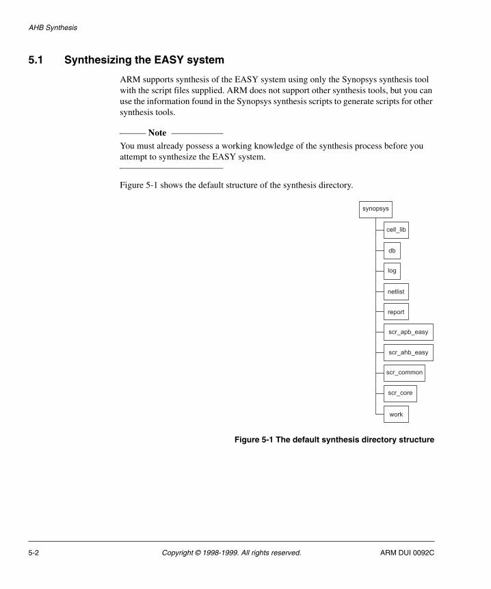
Figure 5-1 shows the default structure of the synthesis directory.
Figure 5-1 The default synthesis directory structure
synopsys
cell_lib
work
netlist
scr_ahb_easy
scr_apb_easy
scr_common
scr_core
db
log
report
5-2 Copyright © 1998-1999. All rights reserved. ARM DUI 0092C
AHB Synthesis
5.2 EASY synthesis process
The following subsections describe the EASY synthesis process:
• Requirements for the default EASY system for synthesis
• Purpose of synthesis scripts
• System synthesis scripts on page 5-4
• Synthesis timing constraints on page 5-6
• Synthesis results on page 5-7
• Using a different technology cell library on page 5-8.
5.2.1 Requirements for the default EASY system for synthesis
The system must have access to the standard Synopsys synthesis tools version 1999.05 or later. To use Synopsys versions earlier than this, some commands in the script files may need modifying due to command changes made in version 1999.05:
1. Ensure that the system directory structure is the same as the default system, so that the synthesis script files can find the correct HDL source files.
2. Choose the HDL RTL input and netlist output settings found in the synopsys/HDL.csh file.
When the system is set up correctly, you can synthesize the EASY modules.
5.2.2 Purpose of synthesis scripts
The standard synthesis process needs a script to:
• read in the RTL HDL source file
• set up the general system parameters
• constrain the port timing
• synthesize the module
• generate area, cell, timing and violation reports
• write out the generated netlist files.
This is done using a single master compile script, scr_common/amba.cmd, which may be used to synthesize all EASY modules. Environmental variables are used to pass settings to this script to select the module to synthesize.
The final area and gate count that will be achieved is dependent on the target cell library use, and synthesis timing constraints and command options. The default synthesis settings are not optimized for speed or area, but for ease of re-use with different technology libraries and clock frequencies.
ARM DUI 0092C Copyright © 1998-1999. All rights reserved. 5-3
AHB Synthesis
5.2.3 System synthesis scripts
The synthesis scripts that are used to synthesize each module in the AHB EASY system are:
amba.cmd The main synthesis command file contains the dc_shell command list used to synthesize the module. This file is cell library and module independent, only using variables and environmental settings that are passed to it.
amba_params.scr The AMBA timing parameters file contains the timing settings for all input and output ports used by all EASY modules, and the system clock frequency (default 50MHz = 20ns clock period). This contains generic timing values for all ports, and may be altered to use more accurate values once the system clock frequency and cell library used are defined.
<module>.scr The synthesis constraints file contains the timing constraints for the module input and output ports that are not included in the standard master and slave .scr files. Also contains any path specific settings that are needed by the module, such as false or multicycle paths.
apb_master.scr, apb_slave.scr, ahb_master.scr and ahb_slave.scr
These four scripts contain generic port timing constraints for the standard APB and AHB signals (such as HRDATA and PRDATA) for APB and AHB masters and slaves (peripherals).
cpu_wrapper.scr This script file is used to set the extra options needed when synthesizing an AHB CPU wrapper, including the top-level name of the wrapper module, and the synopsys timing library names for the CPU.
dont_use.scr The cells in the target library that are not to be used are specified in this script. This file must be modified for the chosen technology library.
gobal.scr This uses parameters from the settings.scr script to define the library worst and best case condition names, and the default cell drive and load strength. This file must be modified for the chosen technology library.
name_rules.scr The name rules used are defined in this file, and are used to ensure that SDF and netlist files are written out with matching names, no invalid characters, and restricted name lengths. This file must be modified for the chosen technology library.
5-4 Copyright © 1998-1999. All rights reserved. ARM DUI 0092C
AHB Synthesis
settings.scr Defines the technology library settings used. This file must be modified for the chosen technology library.
setup.scr The setup script defines the target, link and symbol libraries, the UNIX directory path for synopsys read and write caches, and general system settings used to control synthesis for all system designs. It also includes the settings.scr, dont_use.scr and name_rules.scr script files.
Two shell scripts are used to control the synthesis of AMBA modules:
• HDL.csh is used to set the RTL source HDL used (VHDL or Verilog), and the HDL of the output netlist generated (VHDL, Verilog or both).
• run_all.csh contains the system settings used to control the synthesis of all AMBA modules. This is used to specify the module names and HDL source filenames used during the synthesis of all system modules. The commands found in this script file may be used to synthesize individual AMBA modules.
The following environment variables are used during synthesis:
HDL_IN sets the RTL input HDL that is read.
HDL_OUT sets the netlist output HDL that is written.
HDL_COMP sets the -checkout option of dc_shell to use either VHDL-Compiler or HDL-Compiler.
TOP_NAME sets the top-level name of the module to be synthesized.
OTHER_NAMES sets the names of the modules instantiated by TOP_NAME.
CPU_TOP_NAME sets the top-level name of the CPU wrapper.
CPU_LIB_MAX sets the maximum CPU timing library file.
CPU_LIB_MIN sets the minimum CPU timing library file.
MODULE_TYPE defines the type of module to be synthesized, which can be any one of APB_Master, APB_Slave, AHB_Master, AHB_Slave and Other.
ARM DUI 0092C Copyright © 1998-1999. All rights reserved. 5-5
AHB Synthesis
5.2.4 Synthesis timing constraints
All synthesis timing values are defined in the amba_params.scr script, and are set as multiples of the system clock period, allowing all values to be scaled automatically if the clock frequency used is modified.
The default timing constraint values are:
• Point to point signals:
— 40% output valid
— 50% input setup
— 10% spare slack
• Multiplexed signals:
— 40% output valid
— 20% multiplexer
— 30% input setup
— 10% spare slack
These values are chosen to allow most system ports to use the same timing values, but some signals are valid later than others, so there are exceptions to these timings such as slow CPU outputs and the slave select line which is a decoded version of the address.
The default constraints may be replaced with more accurate values once the system clock frequency and technology library are chosen, allowing more tightly constrained synthesis of the system.
Clock skew needs to be set explicitly as minus (worst case) and plus (best case) uncertainty. The following default values have been used as preliminary values prior to layout:
• minus uncertainty is 5% of the clock period
• plus uncertainty is 40% of the minus uncertainty, which is 2% of the clock period.
The plus uncertainty derives from best case conditions and is less than the minus uncertainty value which derives from worst case conditions.
5-6 Copyright © 1998-1999. All rights reserved. ARM DUI 0092C
AHB Synthesis
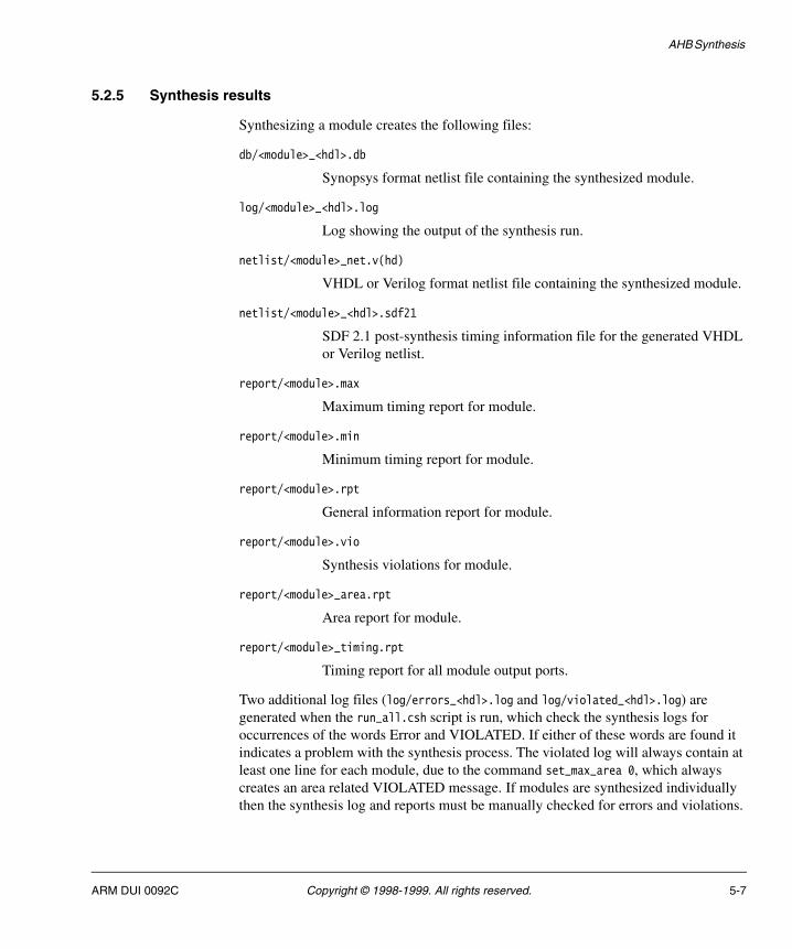
5.2.5 Synthesis results
Synthesizing a module creates the following files:
db/<module>_<hdl>.db
Synopsys format netlist file containing the synthesized module.
log/<module>_<hdl>.log
Log showing the output of the synthesis run.
netlist/<module>_net.v(hd)
VHDL or Verilog format netlist file containing the synthesized module.
netlist/<module>_<hdl>.sdf21
SDF 2.1 post-synthesis timing information file for the generated VHDL or Verilog netlist.
report/<module>.max
Maximum timing report for module.
report/<module>.min
Minimum timing report for module.
report/<module>.rpt
General information report for module.
report/<module>.vio
Synthesis violations for module.
report/<module>_area.rpt
Area report for module.
report/<module>_timing.rpt
Timing report for all module output ports.
Two additional log files (log/errors_<hdl>.log and log/violated_<hdl>.log) are generated when the run_all.csh script is run, which check the synthesis logs for occurrences of the words Error and VIOLATED. If either of these words are found it indicates a problem with the synthesis process. The violated log will always contain at least one line for each module, due to the command set_max_area 0, which always creates an area related VIOLATED message. If modules are synthesized individually then the synthesis log and reports must be manually checked for errors and violations.
ARM DUI 0092C Copyright © 1998-1999. All rights reserved. 5-7
AHB Synthesis
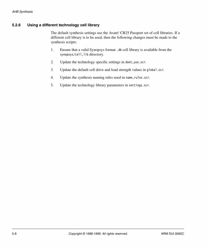
5.2.6 Using a different technology cell library
The default synthesis settings use the Avant! CB25 Passport set of cell libraries. If a different cell library is to be used, then the following changes must be made to the synthesis scripts:
1. Ensure that a valid Synopsys format .db cell library is available from the synopsys/cell_lib directory.
2. Update the technology specific settings in dont_use.scr.
3. Update the default cell drive and load strength values in global.scr.
4. Update the synthesis naming rules used in name_rules.scr.
5. Update the technology library parameters in settings.scr.
5-8 Copyright © 1998-1999. All rights reserved. ARM DUI 0092C
AHB Synthesis
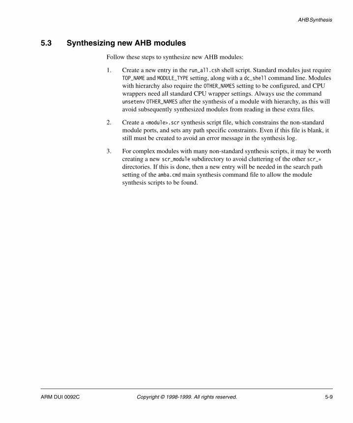
5.3 Synthesizing new AHB modules
Follow these steps to synthesize new AHB modules:
1. Create a new entry in the run_all.csh shell script. Standard modules just require TOP_NAME and MODULE_TYPE setting, along with a dc_shell command line. Modules with hierarchy also require the OTHER_NAMES setting to be configured, and CPU wrappers need all standard CPU wrapper settings. Always use the command unsetenv OTHER_NAMES after the synthesis of a module with hierarchy, as this will avoid subsequently synthesized modules from reading in these extra files.
2. Create a <module>.scr synthesis script file, which constrains the non-standard module ports, and sets any path specific constraints. Even if this file is blank, it still must be created to avoid an error message in the synthesis log.
3. For complex modules with many non-standard synthesis scripts, it may be worth creating a new scr_module subdirectory to avoid cluttering of the other scr_* directories. If this is done, then a new entry will be needed in the search path setting of the amba.cmd main synthesis command file to allow the module synthesis scripts to be found.
ARM DUI 0092C Copyright © 1998-1999. All rights reserved. 5-9

AHB Synthesis
5-10 Copyright © 1998-1999. All rights reserved. ARM DUI 0092C
Appendix A HDL Libraries and Dependencies
This appendix shows the relationships between all the modules, and the libraries they require for use in the following sections:
• AHB VHDL files on page A-2
• AHB Verilog file on page A-6
• ASB VHDL files on page A-8
• ASB Verilog files on page A-11.
ARM DUI 0092C Copyright © 1998-1999. All rights reserved. A-1
HDL Libraries and Dependencies
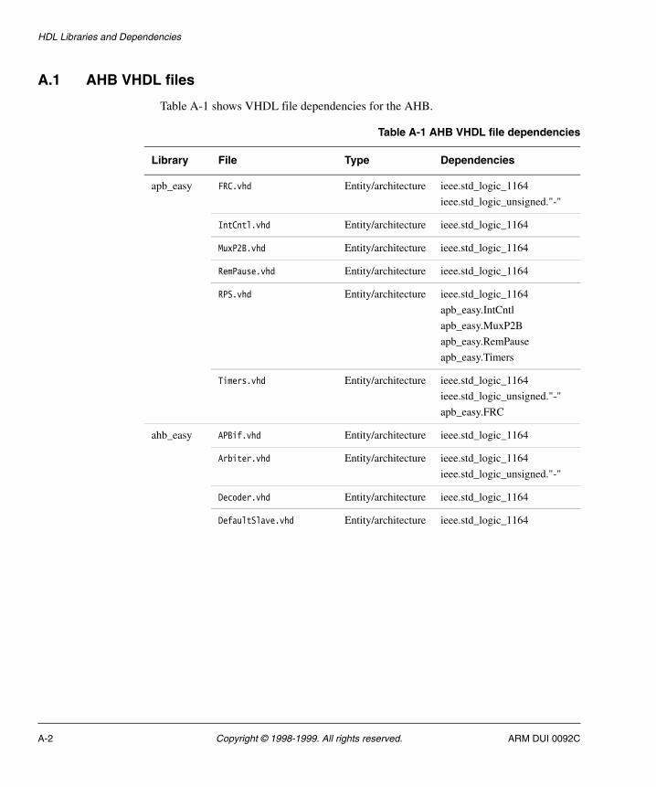
A.1 AHB VHDL files
Table A-1 shows VHDL file dependencies for the AHB.
Table A-1 AHB VHDL file dependencies
Library File Type Dependencies
apb_easy FRC.vhd Entity/architecture ieee.std_logic_1164
ieee.std_logic_unsigned."-"
IntCntl.vhd Entity/architecture ieee.std_logic_1164
MuxP2B.vhd Entity/architecture ieee.std_logic_1164
RemPause.vhd Entity/architecture ieee.std_logic_1164
RPS.vhd Entity/architecture ieee.std_logic_1164
apb_easy.IntCntl
apb_easy.MuxP2B
apb_easy.RemPause
apb_easy.Timers
Timers.vhd Entity/architecture ieee.std_logic_1164
ieee.std_logic_unsigned."-"
apb_easy.FRC
ahb_easy APBif.vhd Entity/architecture ieee.std_logic_1164
Arbiter.vhd Entity/architecture ieee.std_logic_1164
ieee.std_logic_unsigned."-"
Decoder.vhd Entity/architecture ieee.std_logic_1164
DefaultSlave.vhd Entity/architecture ieee.std_logic_1164
A-2 Copyright © 1998-1999. All rights reserved. ARM DUI 0092C
HDL Libraries and Dependencies
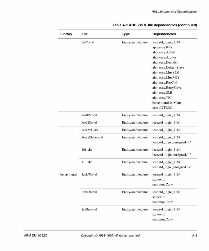
EASY.vhd Entity/architecture ieee.std_logic_1164
apb_easy.RPS
ahb_easy.APBif
ahb_easy.Arbiter
ahb_easy.Decoder
ahb_easy.DefaultSlave
ahb_easy.MuxS2M
ahb_easy.MuxM2S
ahb_easy.ResCntl
ahb_easy.RetrySlave
ahb_easy.SMI
ahb_easy.TIC
behavioural.IntMem
core.A7TDMI
MuxM2S.vhd Entity/architecture ieee.std_logic_1164
MuxS2M.vhd Entity/architecture ieee.std_logic_1164
ResCntl.vhd Entity/architecture ieee.std_logic_1164
RetrySlave.vhd Entity/architecture ieee.std_logic_1164,
ieee.std_logic_unsigned."-"
SMI.vhd Entity/architecture ieee.std_logic_1164,
ieee.std_logic_unsigned."-"
TIC.vhd Entity/architecture ieee.std_logic_1164
ieee.std_logic_unsigned."+"
behavioural ExtRAM.vhd Entity/architecture ieee.std_logic_1164
std.textio
common.Conv
ExtROM.vhd Entity/architecture ieee.std_logic_1164
std.textio
common.Conv
IntMem.vhd Entity/architecture ieee.std_logic_1164
std.textio
common.Conv
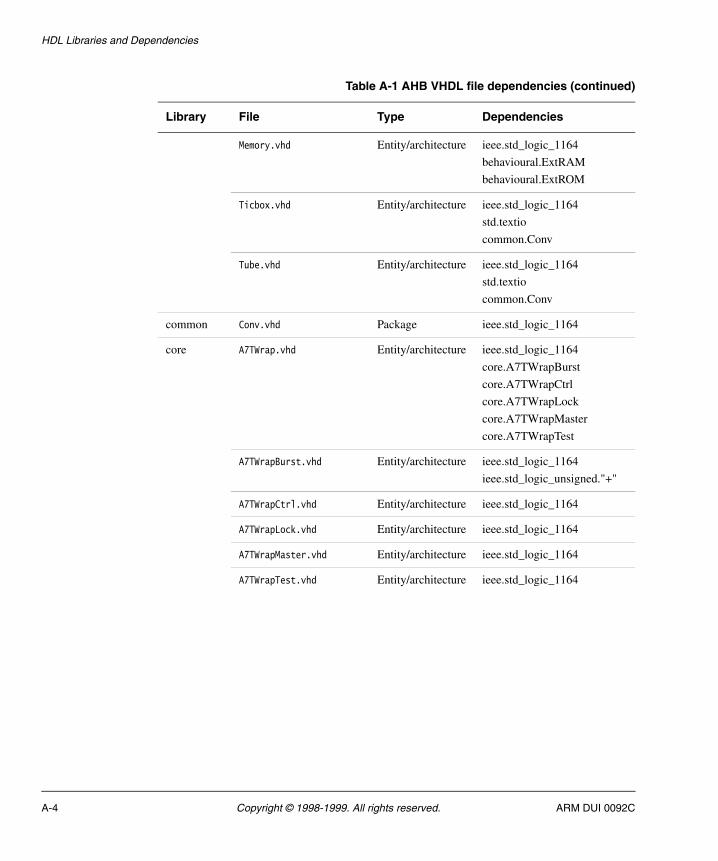
Table A-1 AHB VHDL file dependencies (continued)
Library File Type Dependencies
ARM DUI 0092C Copyright © 1998-1999. All rights reserved. A-3
HDL Libraries and Dependencies
Memory.vhd Entity/architecture ieee.std_logic_1164
behavioural.ExtRAM
behavioural.ExtROM
Ticbox.vhd Entity/architecture ieee.std_logic_1164
std.textio
common.Conv
Tube.vhd Entity/architecture ieee.std_logic_1164
std.textio
common.Conv
common Conv.vhd Package ieee.std_logic_1164
core A7TWrap.vhd Entity/architecture ieee.std_logic_1164
core.A7TWrapBurst
core.A7TWrapCtrl
core.A7TWrapLock
core.A7TWrapMaster
core.A7TWrapTest
A7TWrapBurst.vhd Entity/architecture ieee.std_logic_1164
ieee.std_logic_unsigned."+"
A7TWrapCtrl.vhd Entity/architecture ieee.std_logic_1164
A7TWrapLock.vhd Entity/architecture ieee.std_logic_1164
A7TWrapMaster.vhd Entity/architecture ieee.std_logic_1164
A7TWrapTest.vhd Entity/architecture ieee.std_logic_1164
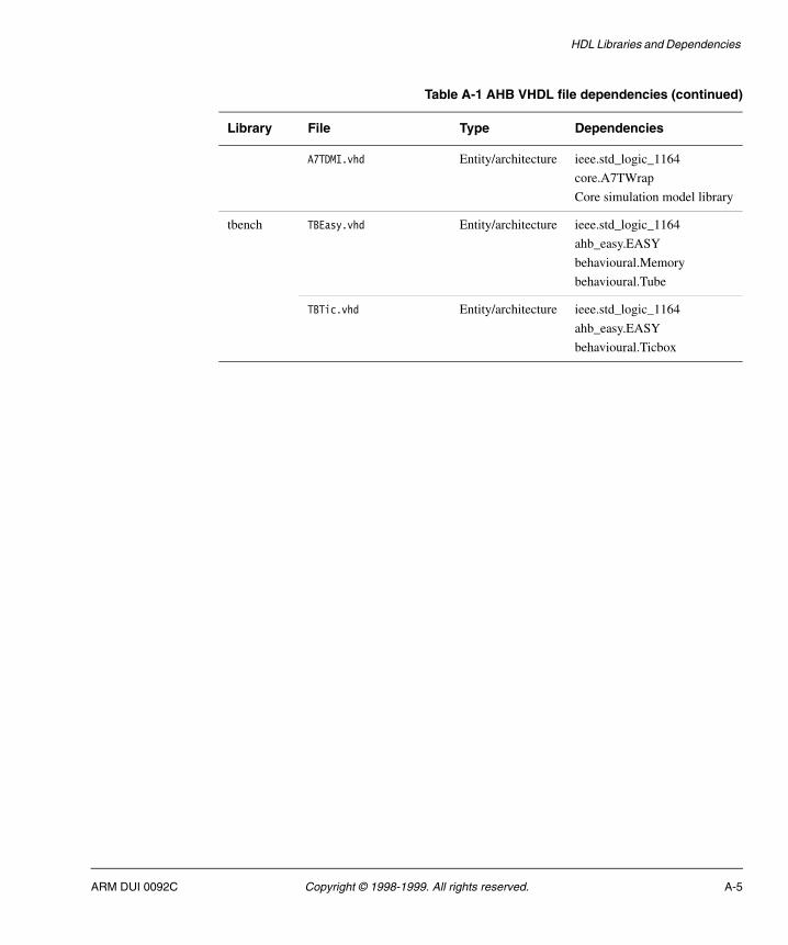
Table A-1 AHB VHDL file dependencies (continued)
Library File Type Dependencies
A-4 Copyright © 1998-1999. All rights reserved. ARM DUI 0092C
HDL Libraries and Dependencies
A7TDMI.vhd Entity/architecture ieee.std_logic_1164
core.A7TWrap
Core simulation model library
tbench TBEasy.vhd Entity/architecture ieee.std_logic_1164
ahb_easy.EASY
behavioural.Memory
behavioural.Tube
TBTic.vhd Entity/architecture ieee.std_logic_1164
ahb_easy.EASY
behavioural.Ticbox
Table A-1 AHB VHDL file dependencies (continued)
Library File Type Dependencies
ARM DUI 0092C Copyright © 1998-1999. All rights reserved. A-5

HDL Libraries and Dependencies
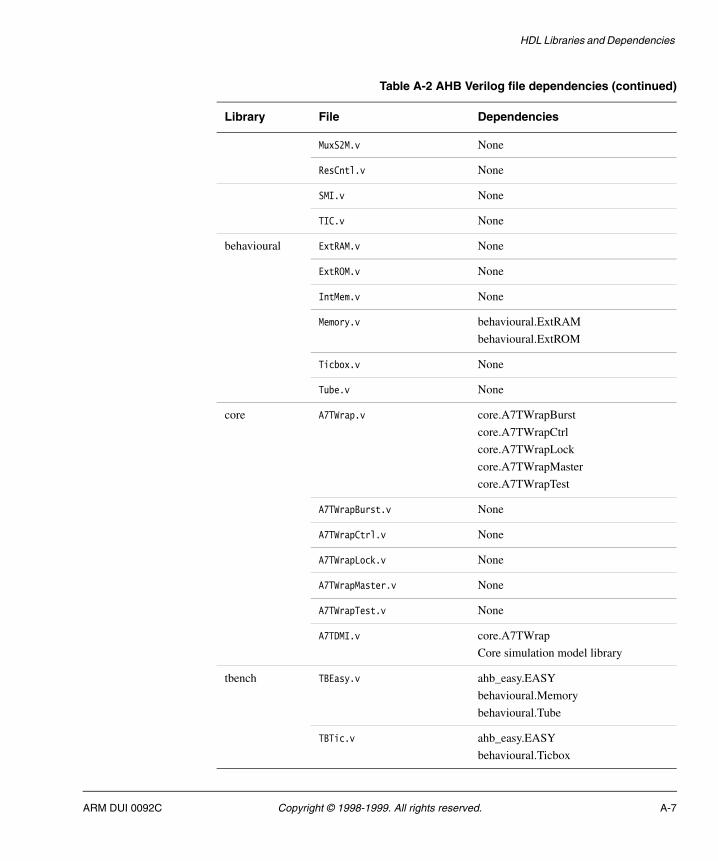
A.2 AHB Verilog file
Table A-2 shows Verilog file dependencies for the AHB.
Table A-2 AHB Verilog file dependencies
Library File Dependencies
apb_easy FRC.v None
IntCntl.v None
MuxP2B.v None
RemPause.v None
RPS.v apb_easy.IntCntl
apb_easy.RemPause
apb_easy.MuxP2B
apb_easy.Timers
Timers.v apb_easy.FRC
ahb_easy APBif.v None
Arbiter.v None
Decoder.v None
DefaultSlave.v None
EASY.v apb_easy.RPS
ahb_easy.APBif
ahb_easy.Arbiter
ahb_easy.Decoder
ahb_easy.DefaultSlave
ahb_easy.MuxS2M
ahb_easy.MuxM2S
ahb_easy.ResCntl
ahb_easy.RetrySlave
ahb_easy.SMI
ahb_easy.TIC
behavioural.IntMem
core.A7TDMI
MuxM2S.v None
A-6 Copyright © 1998-1999. All rights reserved. ARM DUI 0092C
HDL Libraries and Dependencies
MuxS2M.v None
ResCntl.v None
SMI.v None
TIC.v None
behavioural ExtRAM.v None
ExtROM.v None
IntMem.v None
Memory.v behavioural.ExtRAM
behavioural.ExtROM
Ticbox.v None
Tube.v None
core A7TWrap.v core.A7TWrapBurst
core.A7TWrapCtrl
core.A7TWrapLock
core.A7TWrapMaster
core.A7TWrapTest
A7TWrapBurst.v None
A7TWrapCtrl.v None
A7TWrapLock.v None
A7TWrapMaster.v None
A7TWrapTest.v None
A7TDMI.v core.A7TWrap
Core simulation model library
tbench TBEasy.v ahb_easy.EASY
behavioural.Memory
behavioural.Tube
TBTic.v ahb_easy.EASY
behavioural.Ticbox
Table A-2 AHB Verilog file dependencies (continued)
Library File Dependencies
ARM DUI 0092C Copyright © 1998-1999. All rights reserved. A-7
HDL Libraries and Dependencies
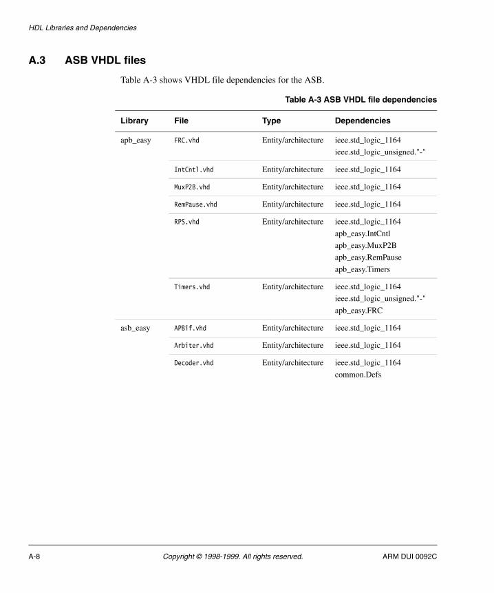
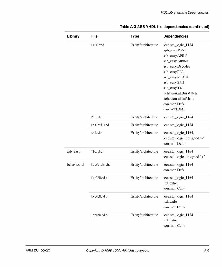
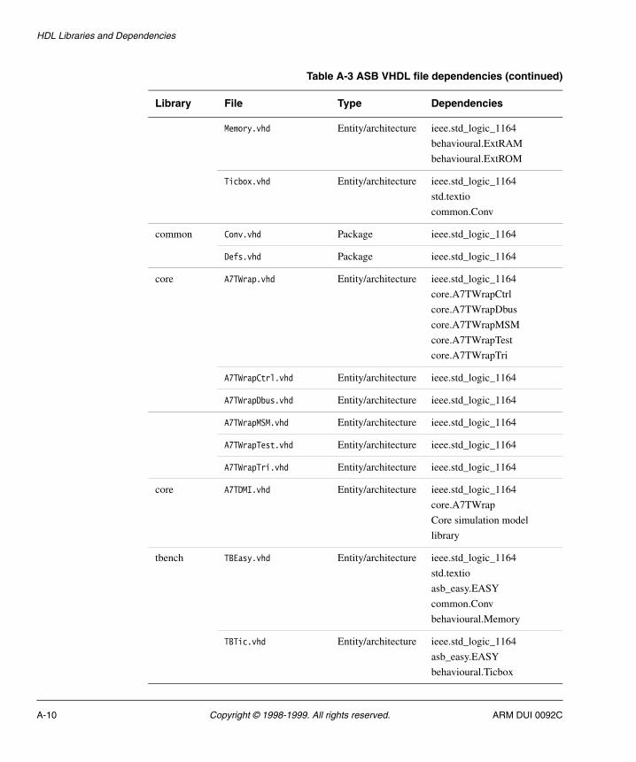
A.3 ASB VHDL files
Table A-3 shows VHDL file dependencies for the ASB.
Table A-3 ASB VHDL file dependencies
Library File Type Dependencies
apb_easy FRC.vhd Entity/architecture ieee.std_logic_1164
ieee.std_logic_unsigned."-"
IntCntl.vhd Entity/architecture ieee.std_logic_1164
MuxP2B.vhd Entity/architecture ieee.std_logic_1164
RemPause.vhd Entity/architecture ieee.std_logic_1164
RPS.vhd Entity/architecture ieee.std_logic_1164
apb_easy.IntCntl
apb_easy.MuxP2B
apb_easy.RemPause
apb_easy.Timers
Timers.vhd Entity/architecture ieee.std_logic_1164
ieee.std_logic_unsigned."-"
apb_easy.FRC
asb_easy APBif.vhd Entity/architecture ieee.std_logic_1164
Arbiter.vhd Entity/architecture ieee.std_logic_1164
Decoder.vhd Entity/architecture ieee.std_logic_1164
common.Defs
A-8 Copyright © 1998-1999. All rights reserved. ARM DUI 0092C
HDL Libraries and Dependencies
EASY.vhd Entity/architecture ieee.std_logic_1164
apb_easy.RPS
asb_easy.APBif
asb_easy.Arbiter
asb_easy.Decoder
asb_easy.PLL
asb_easy.ResCntl
asb_easy.SMI
asb_easy.TIC
behavioural.BusWatch
behavioural.IntMem
common.Defs
core.A7TDMI
PLL.vhd Entity/architecture ieee.std_logic_1164
ResCntl.vhd Entity/architecture ieee.std_logic_1164
SMI.vhd Entity/architecture ieee.std_logic_1164,
ieee.std_logic_unsigned."-"
common.Defs
asb_easy TIC.vhd Entity/architecture ieee.std_logic_1164
ieee.std_logic_unsigned."+"
behavioural BusWatch.vhd Entity/architecture ieee.std_logic_1164
common.Defs
ExtRAM.vhd Entity/architecture ieee.std_logic_1164
std.textio
common.Conv
ExtROM.vhd Entity/architecture ieee.std_logic_1164
std.textio
common.Conv
IntMem.vhd Entity/architecture ieee.std_logic_1164
std.textio
common.Conv
Table A-3 ASB VHDL file dependencies (continued)
Library File Type Dependencies
ARM DUI 0092C Copyright © 1998-1999. All rights reserved. A-9
HDL Libraries and Dependencies
Memory.vhd Entity/architecture ieee.std_logic_1164
behavioural.ExtRAM
behavioural.ExtROM
Ticbox.vhd Entity/architecture ieee.std_logic_1164
std.textio
common.Conv
common Conv.vhd Package ieee.std_logic_1164
Defs.vhd Package ieee.std_logic_1164
core A7TWrap.vhd Entity/architecture ieee.std_logic_1164
core.A7TWrapCtrl
core.A7TWrapDbus
core.A7TWrapMSM
core.A7TWrapTest
core.A7TWrapTri
A7TWrapCtrl.vhd Entity/architecture ieee.std_logic_1164
A7TWrapDbus.vhd Entity/architecture ieee.std_logic_1164
A7TWrapMSM.vhd Entity/architecture ieee.std_logic_1164
A7TWrapTest.vhd Entity/architecture ieee.std_logic_1164
A7TWrapTri.vhd Entity/architecture ieee.std_logic_1164
core A7TDMI.vhd Entity/architecture ieee.std_logic_1164
core.A7TWrap
Core simulation model
library
tbench TBEasy.vhd Entity/architecture ieee.std_logic_1164
std.textio
asb_easy.EASY
common.Conv
behavioural.Memory
TBTic.vhd Entity/architecture ieee.std_logic_1164
asb_easy.EASY
behavioural.Ticbox
Table A-3 ASB VHDL file dependencies (continued)
Library File Type Dependencies
A-10 Copyright © 1998-1999. All rights reserved. ARM DUI 0092C
HDL Libraries and Dependencies
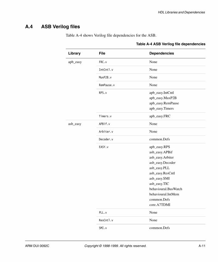
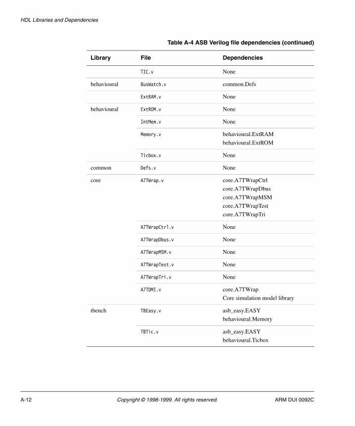
A.4 ASB Verilog files
Table A-4 shows Verilog file dependencies for the ASB.
Table A-4 ASB Verilog file dependencies
Library File Dependencies
apb_easy FRC.v None
IntCntl.v None
MuxP2B.v None
RemPause.v None
RPS.v apb_easy.IntCntl
apb_easy.MuxP2B
apb_easy.RemPause
apb_easy.Timers
Timers.v apb_easy.FRC
asb_easy APBif.v None
Arbiter.v None
Decoder.v common.Defs
EASY.v apb_easy.RPS
asb_easy.APBif
asb_easy.Arbiter
asb_easy.Decoder
asb_easy.PLL
asb_easy.ResCntl
asb_easy.SMI
asb_easy.TIC
behavioural.BusWatch
behavioural.IntMem
common.Defs
core.A7TDMI
PLL.v None
ResCntl.v None
SMI.v common.Defs
ARM DUI 0092C Copyright © 1998-1999. All rights reserved. A-11
HDL Libraries and Dependencies
TIC.v None
behavioural BusWatch.v common.Defs
ExtRAM.v None
behavioural ExtROM.v None
IntMem.v None
Memory.v behavioural.ExtRAM
behavioural.ExtROM
Ticbox.v None
common Defs.v None
core A7TWrap.v core.A7TWrapCtrl
core.A7TWrapDbus
core.A7TWrapMSM
core.A7TWrapTest
core.A7TWrapTri
A7TWrapCtrl.v None
A7TWrapDbus.v None
A7TWrapMSM.v None
A7TWrapTest.v None
A7TWrapTri.v None
A7TDMI.v core.A7TWrap
Core simulation model library
tbench TBEasy.v asb_easy.EASY
behavioural.Memory
TBTic.v asb_easy.EASY
behavioural.Ticbox
Table A-4 ASB Verilog file dependencies (continued)
Library File Dependencies
A-12 Copyright © 1998-1999. All rights reserved. ARM DUI 0092C
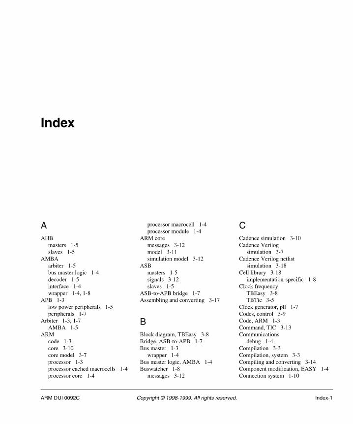
Index
AAHB
masters 1-5slaves 1-5
AMBAarbiter 1-5bus master logic 1-4decoder 1-5interface 1-4wrapper 1-4, 1-8
APB 1-3low power peripherals 1-5peripherals 1-7
Arbiter 1-3, 1-7AMBA 1-5
ARMcode 1-3core 3-10core model 3-7processor 1-3processor cached macrocells 1-4processor core 1-4
processor macrocell 1-4processor module 1-4
ARM coremessages 3-12model 3-11simulation model 3-12
ASBmasters 1-5signals 3-12slaves 1-5
ASB-to-APB bridge 1-7Assembling and converting 3-17
BBlock diagram, TBEasy 3-8Bridge, ASB-to-APB 1-7Bus master 1-3
wrapper 1-4Bus master logic, AMBA 1-4Buswatcher 1-8
messages 3-12
CCadence simulation 3-10Cadence Verilog
simulation 3-7Cadence Verilog netlist
simulation 3-18Cell library 3-18
implementation-specific 1-8Clock frequency
TBEasy 3-8TBTic 3-5
Clock generator, pll 1-7Codes, control 3-9Code, ARM 1-3Command, TIC 3-13Communications
debug 1-4Compilation 3-3Compilation, system 3-3Compiling and converting 3-14Component modification, EASY 1-4Connection system 1-10
ARM DUI 0092C Copyright © 1998-1999. All rights reserved. Index-1
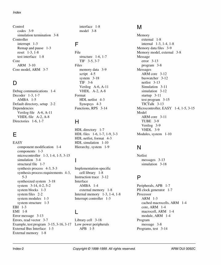
Index
Controlcodes 3-9simulation termination 3-8
Controllerinterrupt 1-3Remap and pause 1-3reset 1-3, 1-8test interface 1-8
CoreARM 3-10
Core model, ARM 3-7
DDebug communications 1-4Decoder 1-3, 1-7
AMBA 1-5Default directory, setup 2-2Dependencies
Verilog file A-6, A-11VHDL file A-2, A-8
Directories 1-6, 1-7
EEASY
component modification 1-4components 1-3microcontroller 1-3, 1-4, 1-5, 3-15simulation 3-4structural file 1-7synthesis process 4-3, 5-3synthesis process requirements 4-3,
5-3synthesized system 3-18system 3-14, 4-2, 5-2system blocks 1-3system files 2-2system modules 1-3system structure 1-3
EBI 1-3EMI 1-8Error message 3-13Errors, read vector 3-7Example, test program 3-15, 3-16, 3-17External Bus Interface 1-3External memory 1-8
interface 1-8model 3-8
FFile
structure 1-6, 1-7TIF 3-5, 3-7
Filesmemory data 3-9script 4-5system 3-18TIF 3-6Verilog A-6, A-11VHDL A-2, A-8
FormatHDL netlist 4-3Synopsys 4-3
Functions, RPS 3-14
HHDL directory 1-7HDL files 1-6, 1-7, 1-9, 3-3HDL netlist, format 4-3HDL simulation 1-10Hierarchy, system 1-9
IImplementation-specific
cell library 1-8Instruction trace 3-12Interface
AMBA 1-4external memory 1-8
Internal memory 1-3, 1-4, 1-8Interrupt controller 1-3
LLibrary cell 3-18Low power peripherals
APB 1-5
MMemory
external 1-8internal 1-3, 1-4, 1-8
Memory data files 3-9Memory model, external 3-8Message
error 3-13program 3-8
MessagesARM core 3-12buswatcher 3-12netlist 3-13Simulation 3-11simulation 3-12startup 3-11test program 3-15TICTalk 3-13
Microcontroller, EASY 1-4, 1-5, 3-15Model
ARM core 3-11TUBE 3-9Verilog 3-9VHDL 3-9
Modules, system 1-10
NNetlist
messages 3-13simulation 3-18
PPeripherals, APB 1-7Pll clock generator 1-7Processor
ARM 1-3cached macrocells, ARM 1-4core, ARM 1-4macrocell, ARM 1-4module, ARM 1-4
Programmessage 3-8
Programs, test 3-14
Index-2 Copyright © 1998-1999. All rights reserved. ARM DUI 0092C
Index
RRead
vector errors 3-7vectors 3-6
Remap and pause controller 1-3Requirements, EASY Synthesis process
4-3, 5-3Reset controller 1-3, 1-8Results, synthesis 4-5RPS
functions 3-14structural file 1-7
SScript files 4-5Scripts, synthesis 4-3, 4-4, 5-3Setup
default directory 2-2simulation 3-2
Signal sequences, TIC 3-5Signals, ASB 3-12Simulation
Cadence 3-10Cadence Verilog 3-7Cadence Verilog netlist 3-18EASY 3-4messages 3-11, 3-12netlist 3-18setup 3-2tool 3-12VHDL netlist 3-18
Simulation modelARM core 3-12
Simulation runtimesreduction 3-9
Simulation terminationcontrol 3-8
SMI 1-3, 1-4Startup messages 3-11Static Memory Interface 1-3, 1-4Structural file
EASY 1-7RPS 1-7
Structurefile 1-6, 1-7system 1-6
Synopsys format 4-3Synthesis
process 4-3, 5-3results 4-5scripts 4-3, 4-4, 5-3tools 4-3, 5-3
Synthesized system, EASY 3-18System
compilation 3-3connection 1-10EASY 3-14, 4-2, 5-2files 3-18hierarchy 1-9modules 1-10structure 1-6TBEasy 3-8Verilog 3-8VHDL 3-8
System files, EASY 2-2
TTBEasy
block diagram 3-8clock frequency 3-8system 3-8test bench 1-10, 3-8, 3-9, 3-10
TBTicclock frequency 3-5test bench 1-10, 3-5, 3-6test bench data 3-5testbench 3-7
Testprograms 3-14TICTalk 3-13
Test benchTBEasy 1-10, 3-8, 3-9, 3-10TBTib 3-6TBTic 1-10, 3-5
Test bench data, TBTic 3-5Test benches 1-8Test Interface Controller 1-3, 3-5Test interface controller 1-8Test patterns
TICTalk 3-6Test program
example 3-15, 3-16, 3-17messages 3-15
TestbenchTBTic 3-7
TICcommand 3-13signal sequences 3-5
TIC Interface Format 3-5TICBOX 3-5, 3-6Ticbox 1-8, 3-7TICTalk
messages 3-13test 3-13test patterns 3-6
TIF 3-5file 3-5, 3-7files 3-6
Timer module, 16-bit 1-3Tools, synthesis 4-3, 5-3Tool, simulation 3-12Trace
instruction 3-12Verilog 3-6
TUBE 3-8, 3-14, 3-15model 3-9
VVectors, read 3-6Verilog
file dependencies A-6, A-11files A-6, A-11model 3-9system 3-8trace 3-6version 3-7
VersionVerilog 3-7VHDL 3-6
VHDLfile dependencies A-2, A-8files A-2, A-8model 3-9netlist simulation 3-18system 3-8version 3-6
ARM DUI 0092C Copyright © 1998-1999. All rights reserved. Index-3
Index
WWrapper
AMBA 1-4, 1-8bus master 1-4
Index-4 Copyright © 1998-1999. All rights reserved. ARM DUI 0092C