(excerpts from boiler, pressure vessel and piping … · excerpts from the following boiler,...
TRANSCRIPT

17 DEPARTMENT OF COMMERCE
Unofficial Text (See Printed Volume). Current through date and Register shown on Title Page.
Register, October, 2005, No. 598
Chapter Comm 41
APPENDIX
(EXCERPTS FROM BOILER, PRESSURE VESSEL AND PIPING CODES AND STANDARDS)
Excerpts from the following boiler, pressure vessel and piping codes and standards are reproduced here strictly for reference: ASMESections I, IV and VIII and ANSI/ASME B31.1. This information has been included to provide a general idea as to the requirementsof these codes and standards. Users of this information must be cautioned that these excerpts do not provide complete guidelines forinspection, installation, operation and manufacturing.
Only portions of each code and standard thought to be frequently used by persons not having direct access to the complete documentshave been included. It must be noted that these codes and standards change on a periodic basis as indicated in s. Comm 41.10. Thosewho are bound by the rules of ch. Comm 41 must avail themselves of the applicable code section or standards listed in s. Comm 41.10.

18 WISCONSIN ADMINISTRATIVE CODE
Unofficial Text (See Printed Volume). Current through date and Register shown on Title Page.
Register, October, 2005, No. 598
EXCERPTS FROM: ASME BOILER AND PRESSURE VESSEL CODESECTION I − POWER BOILERS
2004 EDITIONINTRODUCTION
This Code covers rules for construction of power boilers,1
electric boilers,2 miniature boilers,3 and high−temperaturewater boilers4 to be used in stationary service and includes thosepower boilers used in locomotive, portable, and traction service.Reference to a paragraph includes all the subparagraphs andsubdivisions under that paragraph.
1 Power boiler – a boiler in which steam or other vapor is generated at a
pressure of more than 15 psi (100 kPa) for use external to itself.2 Electric boiler – a power boiler or a high−temperature water boiler in which
the source of heat is electricity.3 Miniature boiler – a power boiler or a high−temperature water boiler in
which the limits specified in PMB−2 are not exceeded.4 High−temperature water boiler – a water boiler intended for operation at
pressures in excess of 160 psi (1.1 MPa) and/or temperatures in excess of
250�F (120�C).
The Code does not contain rules to cover all details of designand construction. Where complete details are not given, it isintended that the manufacturer, subject to the acceptance of theAuthorized Inspector, shall provide details of design andconstruction which will be as safe as otherwise provided by therules in the Code.
The scope of jurisdiction of Section I applies to the boilerproper and to the boiler external piping.
Superheaters, economizers, and other pressure parts con-nected directly to the boiler without intervening valves shall beconsidered as parts of the boiler proper, and their constructionshall conform to Section I rules.
Boiler external piping shall be considered as that pipingwhich begins where the boiler proper or separately fired super-heater terminates at:
(a) the first circumferential joint for welding end connec-tions; or
(b) the face of the first flange in bolted flanged connections;or
(c) the first threaded joint in that type of connection; andwhich extends up to and including the valve or valves requiredby this Code.
ASME Code Certification (including Data Forms and CodeSymbol Stamping), and/or inspection by the Authorized Inspec-tor, when required by this Code, is required for the boiler properand the boiler external piping.
Construction rules for materials, design, fabrication, installa-tion, and testing of the boiler external piping are contained inASME B3.1, Power Piping. Piping beyond the valve or valvesrequired by Section I is not within the scope of Section I, and itis not the intent that the Code Symbol Stamp be applied to suchpiping or any other piping.
The material for forced−circulation boilers, boilers with nofixed steam and water line, and high−temperature water boilers
shall conform to the requirements of the Code. All other require-ments shall also be met except where they relate to special fea-tures of construction made necessary in boilers of these types,and to accessories that are manifestly not needed or used in con-nection with such boilers, such as water gages and water col-umns.
Reheaters receiving steam which has passed through part ofa turbine or other prime mover and separately fired steam super-heaters which are not integral with the boiler are considered firedpressure vessels and their construction shall comply with Coderequirements for superheaters, including safety devices. Pipingbetween the reheater connections and the turbine or other primemover is not within the scope of the Code.
A pressure vessel in which steam is generated by the applica-tion of heat resulting from the combustion of fuel (solid, liquid,or gaseous) shall be classed as a fired steam boiler.
Unfired pressure vessels in which steam is generated shall beclassed as unfired steam boilers with the following exceptions:
(a) vessels known as evaporators or heat exchangers;
(b) vessels in which steam is generated by the use of heatresulting from operation of a processing system containing anumber of pressure vessels such as used in the manufacture ofchemical and petroleum products.
Unfired steam boilers shall be constructed under the provi-sions of Section I or Section VIII.
Expansion tanks required in connection with high−tempera-ture water boilers shall be constructed to the requirements ofSection I or Section VIII.
A pressure vessel in which an organic fluid is vaporized bythe application of heat resulting from the combustion of fuel(solid, liquid, or gaseous) shall be constructed under the provi-sions of Section I. Vessels in which vapor is generated incidentalto the operation of a processing system, containing a number ofpressure vessels such as used in chemical and petroleummanufacture, are not covered by the rules of Section I.
PART PG
GENERAL REQUIREMENTS FORALL METHODS OF CONSTRUCTION
GENERAL
PG−1 SCOPE
The requirements of Part PG apply to power boilers and highpressure, high−temperature water boilers and to parts and appur-tenances thereto and shall be used in conjunction with the spe-cific requirements in the applicable Parts of this Section that per-tain to the methods of construction used.
PG−2 SERVICE LIMITATIONS

19 DEPARTMENT OF COMMERCE
Unofficial Text (See Printed Volume). Current through date and Register shown on Title Page.
Register, October, 2005, No. 598
PG−2.1 The rules of this Section are applicable to the fol-lowing services:
(a) boilers in which steam or other vapor is generated at apressure of more than 15 psig (100kPa)
(b) high−temperature water boilers intended for operation atpressures exceeding 160 psig (1.1 MPa) and/or temperaturesexceeding 250�F (120�C)
PG−2.2 For services below those specified in PG−2.1 it isintended that rules of Section IV apply; however, boilers forsuch services may be constructed and stamped in accordancewith this Section provided all applicable requirements are met.
PG−2.3 Coil−type hot water boilers where the water canflash into steam when released directly to the atmospherethrough a manually operated nozzle may be exempted from therules of this Section provided the following conditions are met:
(a) There is no drum, header, or other steam space.
(b) No steam is generated within the coil.
(c) Tubing outside diameter does not exceed 1 in. (25 mm).
(d) Pipe size does not exceed NPS 3/4 (DN 20).
(e) Nominal water capacity does not exceed 6 gal (23 L).
(f) Water temperature does not exceed 350�F (175�C).
(g) Adequate safety relief valves and controls are provided.
PG−3 REFERENCED STANDARDS
Specific editions of standards referenced in this Section areshown in A−360.
PG−4 UNITS
Either U.S. Customary units or SI units may be used for com-pliance with all requirements of this edition, but one system shallbe used consistently throughout for all phases of construction.
Either the U.S. Customary units or SI units that are listed inMandatory Appendix II are identified in the text, or are identi-fied in the nomenclature for equations, shall be used consistentlyfor all phases of construction (e.g., materials, design, fabrica-tion, and reports). Since values in the two systems are not exactequivalents, each system shall be used independently of theother without mixing U.S. Customary units and SI units.
When SI units are selected, U.S. Customary values in refer-enced specifications that do not contain SI units shall be con-verted to SI values to at least three significant figures for use incalculations and other aspects of construction.
MATERIALS
PG−5 GENERAL
PG−5.1 Material subject to stress due to pressure shall con-form to one of the specifications given in Section II and shall belimited to those that are listed in the Tables of Section II, Part D,except as otherwise permitted in PG−8.2, PG−8.3, PG−10, andPG−11. Materials shall not be used at temperatures above thosefor which stress values are limited, for Section I construction, inthe Tables of Section II, Part D. Specific additional require-
ments described in PG−5 through PG−13 shall be met as applica-ble.
PG−5.2 Material covered by specifications in Section II isnot restricted as to the method of production unless so stated inthe specification, and as long as the product complies with therequirements of the specification.
PG−5.3 If, in the development of the art of boiler construc-tion, it is desired to use materials other than those hereindescribed, data should be submitted to the Boiler and PressureVessel Committee in accordance with the requirements ofAppendix 5 of Section II, Part D. Material not completely iden-tified with any approved Code specifications may be used in theconstruction of boilers under the conditions outlined in PG−10.
PG−5.4 Size Limits and Tolerances
PG−5.4.1 Materials outside the limits of size or thicknessgiven in the title or scope clause of any specification in SectionII may be used if the material is in compliance with the otherrequirements of the specification, and no similar limitation isgiven in the rules for construction.
PG−5.4.2 Pipe having a tolerance of ±1% on either the O.D.or the I.D. rather than the tolerance specified in the materialspecification, may be used, provided the material complies withall other requirements of the specifications. When used underexternal pressure, such pipe shall be limited to a maximum of 24in. (600 mm) in diameter. The pipe shall include the designation1% O.D. or 1% I.D., as appropriate, in any required documenta-tion and marking of the material.
PG−5.5 The use of austenitic alloy steel is permitted forboiler pressure parts that are steam touched in normal operation.Except as specifically provided in PG−9.1.1, PG−12, andPEB−5.3, the use of such austenitic alloys for boiler pressureparts that are water wetted in normal service is prohibited.1
1 Austenitic alloys are susceptible to intergranular corrosion and stress
corrosion cracking when used in boiler applications in water wetted service.
Factors that affect the sensitivity to these metallurgical phenomena are
applied or residual stress and water chemistry. Susceptibility to attack is
usually enhanced by using the material in a stressed condition with a con-
centration of corrosive agents (e.g., chlorides, caustic, or reduced sulfer
species). For successful operation in water environments, residual and
applied stresses must be minimized and careful attention must be paid to
continuous control of water chemistry.
PG−6 PLATE
PG−6.1 Steel plates for any part of a boiler subject to pres-sure, whether or not exposed to the fire or products of combus-tion, shall be of pressure vessel quality in accordance with oneof the following specifications:
SA−202 Pressure Vessel Plates, Alloy Steel, Chromium−Manganese−SiliconSA−204 Pressure Vessel Plates, Alloy Steel, MolybdenumSA−240 (Type 405 only) Pressure Vessel Plates, Alloy Steel(Ferritic Stainless), ChromiumSA−285 Pressure Vessel Plates, Carbon Steel, Low−andIntermediate−Tensile StrengthSA−299 Pressure Vessel Plates, Carbon Steel, Manganese−Silicon
20WISCONSIN ADMINISTRATIVE CODE
Unofficial Text (See Printed Volume). Current through date and Register shown on Title Page.
Register, October, 2005, No. 598
SA−302 Pressure Vessel Plates, Alloy Steel, Manganese−Molybdenum and Manganese−Molybdenum−NickelSA−387 Pressure Vessel Plates, Alloy Steel, Chromium−Mo-lybdenumSA−515 Pressure Vessel Plates, Carbon Steel, for Intermedi-ate− and Higher−Temperature ServiceSA−516 Pressure Vessel Plates, Carbon Steel, for Moderate−and Lower−Temperature ServiceSA/AS 1548 Steel Plates for Pressure EquipmentSA/EN−10028−2 Flat Products Made of Steels for PressurePurposesSA/JIS G3118 Carbon Steel Plates for Pressure Vesselsfor Intermediate and Moderate Temperature Service
PG−55 SUPPORTS AND ATTACHMENT LUGS
PG−55.1 Lugs or hangers when used to support a boiler ofany type shall be properly fitted to the surfaces to which they areattached.
PG−55.2 Lugs, hangers, or brackets may be attached byfusion welding provided the welding meets the requirements ofPart PW, including stress relieving but omitting radiographicexamination and provided they are attached by full penetrationwelds, combination groove and fillet welds, or by fillet weldsalong the entire periphery or contact edges. Some acceptableforms of welds for lugs, hangers, or brackets are shown in Fig.PW−16.2. The materials for lugs, hangers, or brackets are notlimited to those listed in Tables 1A and 1B of Section II, Part D,but shall be of weldable quality. The allowable load on the filletwelds shall equal the product of the weld area based on mini-mum leg dimension, the allowable stress value in tension of thematerial being welded, and the factor 0.55. When using weldedpipe, the stress values given in Table 1A of Section II, Part D,may be increased to that of the basic material by eliminating thestated weld efficiencies.
BOILER EXTERNAL PIPINGAND BOILER PROPER CONNECTIONS
PG−58 OUTLETS AND EXTERNAL PIPING
PG−58.1 General. The rules of this subparagraph apply tothe boiler external piping as defined in the Preamble.
PG−58.2 Boiler External Piping Connections to Boilers.All boiler external piping connected to a boiler for any purposeshall be attached to one of the types of joints listed inPG−59.1.1.1, PG−59.1.1.2, and PG−59.1.1.3.
PG−58.3 Boiler External Piping. The following defines theCode Jurisdictional Limits of the boiler external piping systems,including general requirements, valves, and inspection. Thelimits are also shown in Figs. PG−58.3.1 and PG−58.3.2. Thematerials, design, fabrication, installation, and testing shall be inaccordance with ASME B31.1, Power Piping.
PG−58.3.1 The steam piping connected to the boiler drumor to the superheater outlet header shall extend up to and includ-ing the first stop valve in each connection, except as required byPG−58.3.2. In the case of a single boiler and prime mover instal-lation, the stop valve required herein may be omitted provided
the prime mover throttle valve is equipped with an indicator toshow whether the valve is open or closed and is designed to with-stand the required hydrostatic pressure test of the boiler.
For an isolable or separately fired superheater which dis-charges steam directly to a process stream, the stop valverequired by this paragraph and the safety valve(s) required byPG−68 may be omitted provided the following conditions aresatisfied:
(a) The boiler is a drum−type boiler in a single−boiler instal-lation.
(b) The steam discharge passes through the process streamto the atmosphere with no intervening valves.
(c) The system shall be designed so that the process streamthrough which the steam discharge passes cannot be obstructedin such a way as to cause the pressure in the superheater toexceed that permitted by PG−67.2, with maximum steam flowfrom the boiler to the superheater. Flow and pressure calcula-tions demonstrating that the superheater will not be overpressur-ized under any steam flow conditions shall be documented andmade available to the Inspector. These calculations shall be cer-tified by a Professional Engineer experienced in the mechanicaldesign of power plants.
(d) There is no valve on the discharge side of the superheater.
(e) Section I jurisdiction shall include the pressure partsbetween the superheater inlet and the outlet at:
(1) the first circumferential joint for welding end connec-tions; or
(2) the face of the first flange in bolted flange connections;or
(3) the first threaded joint in that type of connection.
PG−58.3.2 When two or more boilers are connected to acommon steam header, or when a single boiler is connected toa header having another steam source (e.g., a turbine extractionline), the connection from each boiler having a manhole openingshall be fitted with two stop valves having an ample free−blowdrain between them. The boiler external piping includes all pip-ing from the boiler proper up to and including the second stopvalve and the free−blow drain valve.
PG−58.3.3 The feedwater piping for all boilers, except high−temperature water boilers and forced−flow steam generatorscomplying with PG−58.3.5, shall extend through the requiredstop valve and up to and including the check valve except asrequired by PG−58.3.4. On a single boiler−turbine unit installa-tion the boiler feed shutoff valve may be located upstream fromthe boiler feed check valve.
If a feedwater heater or heaters meeting the requirements ofPart PFH are installed between the required stop valve and theboiler, and are fitted with isolation and bypass valves, provisionsmust be made to prevent the feedwater pressure from exceedingthe maximum allowable working pressure of the piping orheater, whichever is less. Control and interlock systems are per-mitted in order to prevent overpressure.
21 DEPARTMENT OF COMMERCE
Unofficial Text (See Printed Volume). Current through date and Register shown on Title Page.
Register, October, 2005, No. 598
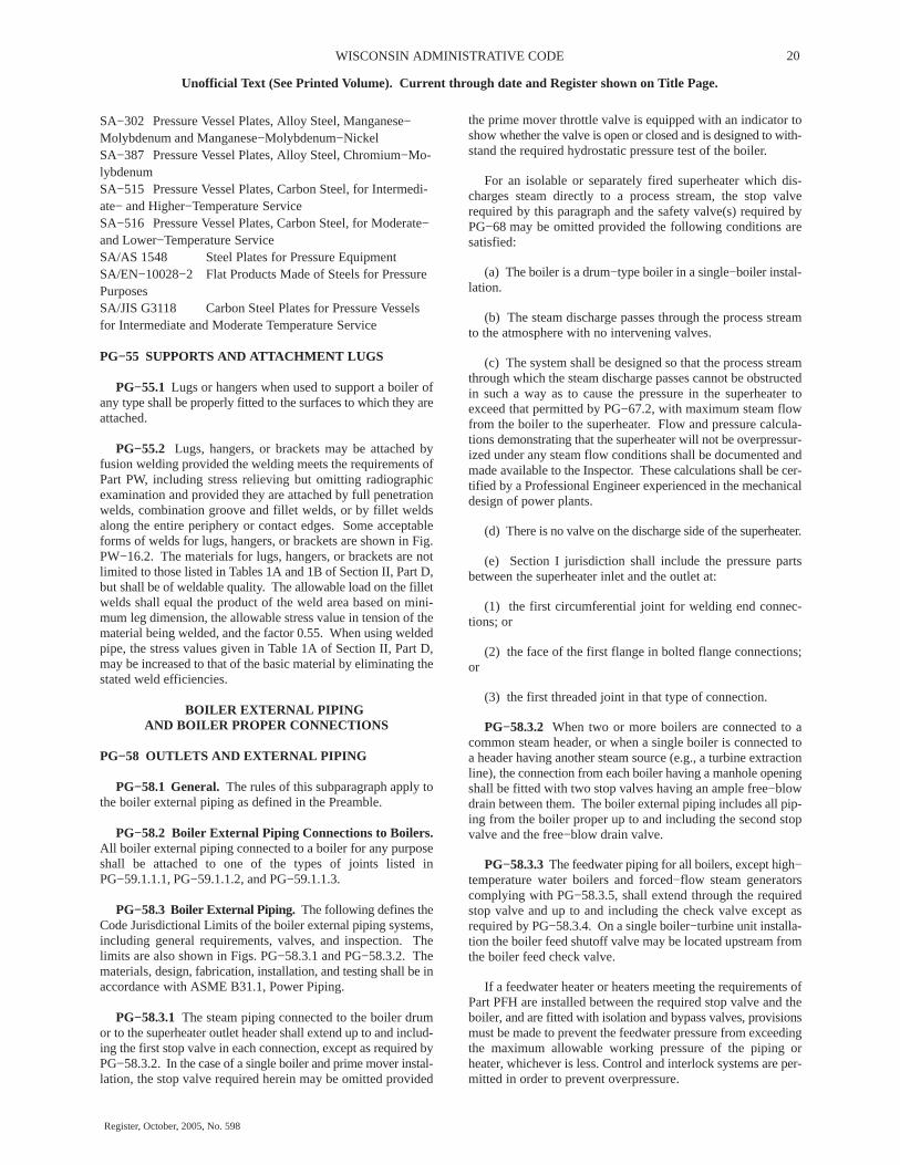
ADMINISTRATIVE JURISDICTION & TECHNICAL RESPONSIBILITY
Boiler Proper − The ASME Boiler and Pressure Vessel Code (ASME BPVC) has total administrative jurisdiction and technicalresponsibility (refer to Section I Preamble).
�—— Boiler External Piping and Joint − The ASME BPVC has total administrative jurisdiction (mandatory certification by CodeSymbol stamping, ASME Data Forms, and Authorized Inspection) of Boiler External Piping and Joint. The ASME Section CommitteeB31.1 has been assigned technical responsibility.
ο− − − Non−Boiler External Piping and Joint − Not Section I jurisdiction (see applicable ASME B31 Code).
FIG. PG−58.3.1 CODE JURISDICTIONAL LIMITS FOR PIPING − DRUM TYPE BOILERS

22WISCONSIN ADMINISTRATIVE CODE
Unofficial Text (See Printed Volume). Current through date and Register shown on Title Page.
Register, October, 2005, No. 598
Alternates PG−58.3.5
Start−up system may vary to suit boiler manufacturer
Turbine valve or code stop valve PG−58.3.1
Superheater
Reheater
Convection and radiant section
Economizer
Boiler feed pump
Condenser
To equipment
Turbine
NEL—6/11/96
ADMINISTRATIVE JURISDICTION & TECHNICAL RESPONSIBILITY
____ Boiler Proper − The ASME Boiler and Pressure Vessel Code (ASME BPVC) has total administrative jurisdiction and technicalresponsibility (refer to Section I Preamble).
�—— Boiler External Piping and Joint − The ASME BPVC has total administrative jurisdiction (mandatory certification by CodeSymbol stamping, ASME Data Forms, and Authorized Inspection) of Boiler External Piping and Joint. The ASME Section CommitteeB31.1 has been assigned technical responsibility.
ο− − − Non−Boiler External Piping and Joint − Not Section I jurisdiction (see applicable ASME B31 Code).
FIG. PG−58.3.2 CODE JURISDICTIONAL LIMITS FOR PIPING − FORCED−FLOW STEAM GENERATOR WITH NO FIXEDSTEAM OR WATERLINE
23 DEPARTMENT OF COMMERCE
Unofficial Text (See Printed Volume). Current through date and Register shown on Title Page.
Register, October, 2005, No. 598
PG−58.3.4 When two or more boilers are fed from a com-mon source, the piping shall be up to and including a globe orregulating valve located between the check valve required inPG−58.3.3 and the source of supply. If the regulating valve isequipped with an isolation valve and a bypass valve, the pipingshall be up to and including both the isolation valve downstreamfrom the regulating valve and the shutoff valve in the bypass.
PG−58.3.5 The feedwater piping for a forced−flow steamgenerator with no fixed steam and waterline may terminate upto and including the stop valve near the boiler and omitting thecheck valve near the boiler, provided that a check valve havinga pressure rating no less than the boiler inlet design pressure isinstalled at the discharge of the boiler feed pump or elsewherein the feedline between the feed pump and the feed stop valve.If the feedwater heater(s) is fitted with isolation and bypassvalves, the applicable requirements of PG−58.3.3 must be met.
PG−58.3.6 The blowoff piping for all boilers, except forced−flow steam generators with no fixed steam and waterline, high−temperature water boilers, and those used for traction and/orportable purposes, when the maximum allowable working pres-sure exceeds 100 psi (700kPa) shall extend through and includ-ing the second valve. The blowoff piping for all traction and/orportable boilers and for forced circulation and electric boilershaving a normal water content not exceeding 100 gal (380 L) arerequired to extend through only one valve.
PG−58.3.7 The miscellaneous piping shall include the pip-ing for such items as drains, vents, surface−blow−off, steam andwater piping for water columns, gage glasses and pressuregages, and the recirculation return line for a high−temperaturewater boiler. When a drain is not intended for blowoff purposes(when the boiler is under pressure) a single valve is acceptable,otherwise two valves in series are required except as permittedby PG−58.3.6.
PG−58.3.8 Welded piping in PG−58.3.1, PG−58.3.2,PG−58.3.3, PG−58.3.4, PG−58.3.5, PG−58.3.6, and PG−58.3.7is also subject to the requirements of PG−104 for proper Codecertification.
PG−59 APPLICATION REQUIREMENTS FOR THEBOILER PROPER
PG−59.1 Common to Steam, Feedwater, Blowoff, andDrain Systems
PG−59.1.1 Outlets of a boiler to which piping is to beattached for any purpose, and which piping comes within theCode requirements, shall meet the requirements of PG−39 andshall be:
PG−59.1.1.1 A tapped opening.
PG−59.1.1.2 Bolted flanged joints including those of the VanStone type.
PG−59.1.1.3 Welding ends of the butt or socket weldingtype.
PG−59.1.1.4 Piping within the boiler proper may beexpanded into grooved holes, seal welded if desired. Blowoffpiping of firetube boilers shall be attached by threading into atapped opening with a threaded fitting or valve at the other endif exposed to products of combustion, or by PG−59.1.1.1 orPG−59.1.1.2 if not so exposed (see PFT−49).
PG−59.1.2 Steam Mains. Provisions shall be made for theexpansion and contraction of steam mains connected to boilers,by providing substantial anchorage at suitable points, so thatthere shall be no undue strain transmitted to the boiler. Steamreservoirs shall be used on steam mains when heavy pulsationsof the steam currents cause vibration of the boiler shell plates.
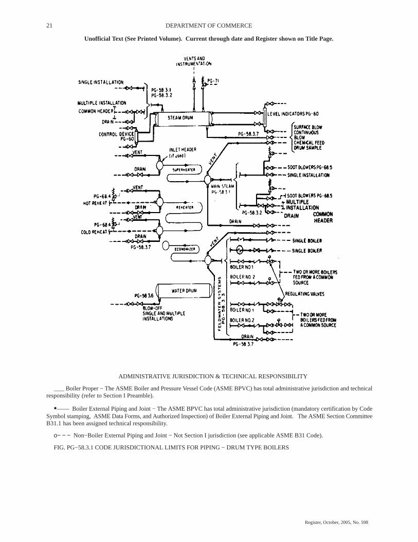
FIG. PG−59.1 TYPICAL BOILER BUSHINGS
PG−59.1.3 Figure PG−59.1 illustrates a typical form of con-nection for use on boiler shells for passing through piping suchas feed, surface blowoff connections, etc., and which permits thepipes’ being threaded in solid from both sides in addition to thereinforcing of the opening of the shell. The pipes shall beattached as provided in PG−59.1.1.
In these and other types of boilers where both internal andexternal pipes making a continuous passage are employed, theboiler bushing or its equivalent shall be used.
PG−59.2 Requirements for Feedwater Connections. Thefeedwater shall be introduced into a boiler in such a manner thatthe water will not be discharged directly against surfacesexposed to gases of high temperature or to direct radiation fromthe fire. For pressures of 400 psi (3 MPa) or over, the feedwaterinlet through the drum shall be fitted with shields, sleeves, orother suitable means to reduce the effects of temperature differ-entials in the shell or head. Feedwater, other than condensatereturns as provided for in PG−59.3.6, shall not be introducedthrough the blowoff.

24WISCONSIN ADMINISTRATIVE CODE
Unofficial Text (See Printed Volume). Current through date and Register shown on Title Page.
Register, October, 2005, No. 598
PG−59.3 Requirements for Blowoffs
PG−59.3.1 A blowoff as required herein is defined as a pipeconnection provided with valves located in the external pipingthrough which the water in the boiler may be blown out underpressure, excepting drains such as are used on water columns,gage glasses, or piping to feedwater regulators, etc., used for thepurpose of determining the operating condition of such equip-ment. Piping connections used primarily for continuous opera-tion, such as deconcentrators on continuous blowdown systems,are not classed as blowoffs but the pipe connections and all fit-tings up to and including the first shutoff valve shall be equal atleast to the pressure requirements for the lowest set pressure ofany safety valve on the boiler drum and with the correspondingsaturated−steam temperature.
PG−59.3.2 A surface blowoff connection shall not exceedNPS 2 1/2 (DN 65), and the internal pipe and the terminal con-nection for the external pipe, when used, shall form a continuouspassage, but with clearance between their ends and arranged sothat the removal of either will not disturb the other. A properlydesigned steel bushing, similar to or the equivalent of thoseshown in Fig. PG−59.1, or a flanged connection shall be used.
PG−59.3.3 Each boiler except forced−flow steam generatorswith no fixed steam and waterline and high−temperature waterboilers shall have a bottom blowoff outlet in direct connectionwith the lowest water space practicable for external piping con-forming to PG−58.3.6.
PG−59.3.4 All waterwalls and water screens that do notdrain back into the boiler, and all integral economizers, shall beequipped with outlet connections for a blowoff or drain line andconform to the requirements of PG−58.3.6 or PG−58.3.7.
PG−59.3.5 Except as permitted for miniature boilers in PartPMB, the minimum size of blowoff connections shall be NPS 1(DN 25), and the maximum size shall be NPS 2 1/2 (DN 65),except that for boilers with 100 ft2 (9.3 m2) of heating surfaceor less, the minimum size of blowoff connections may be NPS3/4 (DN 20).
PG−59.3.6 Condensate return connections of the same sizeor larger than the size herein specified may be used, and theblowoff may be connected to them. In such case the blowoffshall be so located that the connection may be completelydrained.
PG−59.3.7 A bottom blowoff pipe when exposed to directfurnace heat shall be protected by firebrick or other heat resist-ing material that is so arranged that the pipe may be inspected.
PG−59.3.8 An opening in the boiler setting for a blowoffpipe shall be arranged to provide free expansion and contraction.
PG−59.4 Requirements for Drains
PG−59.4.1 Ample drain connections shall be providedwhere required to permit complete drainage of all piping, super-heaters, waterwalls, water screens, integral economizers, high−temperature water boilers, and all other boiler components inwhich water may collect. Piping shall conform to the require-ments of PG−58.3.6 or PG−58.3.7.
PG−59.4.1.1 Each superheater shall be equipped with atleast one drain connection so located as to most effectively pro-vide for the proper operation of the apparatus.
PG−59.4.1.2 Each high−temperature water boiler shall havea bottom drain connection of at least NPS 1 (DN 25) in directconnection with the lowest water space practical for externalpiping conforming to PG−58.3.7.
PG−59.5 Requirements for Valves and Fittings. The fol-lowing requirements apply to the use of valves and fittings in theboiler proper.
PG−59.5.1 Steam Stop Valves
PG−59.5.1.1 If a shutoff valve is used between the boiler andits superheater, the safety valve capacity on the boiler shall com-ply with the requirements of PG−67.2 and PG−70, except as pro-vided for in PG−59.5.1.2, no credit being taken for the safetyvalve on the superheater, and the superheater must be equippedwith safety valve capacity as required by PG−68. A stop valveis not required at the inlet or the outlet of a reheater or separatelyfired superheater.
PG−59.5.1.2 When stop valves are installed in the water−steam flow path between any two sections of a forced–flowsteam generator with no fixed steam and waterline, the safetyvalves shall satisfy the requirements of PG−67.4.4.
DESIGN AND APPLICATION
PG−60 REQUIREMENTS FOR MISCELLANEOUSPIPE, VALVES, AND FITTINGS
Piping referred to in this paragraph shall be designed inaccordance with the applicable requirements of ASME B31.1.
PG−60.1 Water Level Indicators All boilers having a fixedwater level (steam and water interface) shall have at least onegage glass (a transparent device that permits visual determina-tion of the water level). Boilers not having a fixed water level,such as forced−flow steam generators and high−temperaturewater boilers of the forced circulation type, are not required tohave a gage glass. The lowest visible water level in a gage glassshall be at least 2 in. (50 mm) above the lowest permissible waterlevel, as determined by the boiler Manufacturer. Electrode−typeelectric boilers are required to have only one gage glass, regard-less of MAWP.
Gage glasses having multiple tubular sections shall have aminimum of 1 in. (25 mm) overlap of the sections in which thewater level may be visible. Segmented gage glasses, such asported or end−connected strip gages, shall be equipped to pro-vide obvious visual discrimination between water and vapor inthe individual sections.
PG−60.1.1 Boilers having a maximum allowable workingpressure exceeding 400 psi (3 MPa) shall have two gage glasses.Instead of one of the two required gage glasses, two independentremote water level indicators (two discrete systems that continu-ously measure, transmit, and display water level) may be pro-vided.
PG−60.1.1.1 When the water level in at least one gage glassis not readily visible to the operator in the area where controlactions are initiated, either a fiber optic cable (with no electricalmodification of the optical signal) or mirrors shall be provided

25 DEPARTMENT OF COMMERCE
Unofficial Text (See Printed Volume). Current through date and Register shown on Title Page.
Register, October, 2005, No. 598
to transfer the optical image of the water level to the control area.Alternatively, any combination of two of the following shall beprovided:
(a) an independent remote water level indicator
(b) an independent continuous transmission and display ofan image of the water level in a gage glass.
PG−60.1.1.2 When two independent remote water levelindicators are in reliable operation (continuously indicatingwater level), the one required gage glass may be shut off, butshall be maintained in the serviceable condition.
PG−60.1.1.3 The display of a remote water level indicatorshall have a clearly marked minimum water level reference atleast 2 in. (50 mm) above the lowest permissible water level, asdetermined by the Manufacturer.
PG−60.1.6 Each gage glass shall be fitted with a drain cockor valve having an unrestricted drain opening of not less than 1/4in. (6 mm) diameter to facilitate cleaning. When the boilerMAWP exceeds 100 psi (700 kPa), the gage glass shall be fur-nished with a connection to install a valved drain to a point ofsafe discharge.
Each gage glass shall be equipped with a top and a bottomshutoff valve of such through−flow construction as to preventstoppage by deposits of sediments. If the bottom valve is morethan 7 ft (2 m) above the floor or platform from which it is oper-ated, the operating mechanism shall indicate by its positionwhether the valve is open or closed. The pressure—temperaturerating of valves, fittings, and piping shall be at least equal to theboiler MAWP and the corresponding saturated−steam tempera-ture.
Straight−run globe valves shall not be used on such connec-tions. Automatic shutoff valves, if permitted to be used, shallconform to the requirements given in A−18.
PG−60.2 Water Columns
PG−60.2.1 A water column shall be so mounted that it willbe correctly positioned, relative to the normal water level underoperating conditions.
PG−60.2.3 Each water column shall be furnished with a con-nection of at least NPS 3/4 (DN 20) to install a valved drain to asafe point of discharge.
PG−60.2.4 The design and material of a water column shallcomply with the requirements of PG−8.2, PG−8.3, and PG−42.
PG−60.3 Connections
PG−60.3.1 Gage glasses that are required by PG−60.1 shallbe connected directly to the shell or drum of the boiler or to anintervening water column. When two gage glasses are required,both may be connected to a single water column.
PG−60.3.2 The lower edge of the steam connection betweena water column or gage glass in the boiler shall not be below thehighest visible water level in the gage glass. There shall be nosag or offset in the piping that will permit the accumulation ofwater.
PG−60.3.3 The upper edge of the water connection betweena water column or gage glass and the boiler shall not be abovethe lowest visible water level in the gage glass. No part of thispipe connection shall be above the point of connection at thewater column.
PG−60.3.4 Connections from the boiler to the water columnshall be at least NPS 1 (DN 25). Connections for gage glassesconnected directly to the boiler or to an intervening water col-umn shall be at least NPS 1/2 (DN 15). Connections from theboiler to the remote level indicator shall be at least NPS 3/4 (DN20) to and including the isolation valve and from there to theremote level indicator at least � in. (13 mm) O. D. tubing.
PG−60.3.5 When the boiler MAWP exceeds 400 psi (3MPa), lower connections to drums for water columns andremote level indicators shall be provided with shields, sleeves,or other suitable means to reduce the effect of temperature dif-ferentials in the shells or heads.
PG−60.3.6 The steam and water connections to a water col-umn or a gage glass shall be readily accessible for internalinspection and cleaning. Some acceptable methods of meetingthis requirement are by providing a cross or fitting with a backoutlet at each right−angle turn to permit inspection and cleaningin both directions, or by using pipe bends or fittings of a type thatdoes not leave an internal shoulder or pocket in the pipe connec-tion and with a radius of curvature that will permit the passageof a rotary cleaner. Screwed plug closures using threaded con-nections as allowed by PG−39.5.3 are acceptable means ofaccess for this inspection and cleaning. When the boiler MAWPexceeds 400 psig (3 MPa), socket−welded plugs may be used forthis purpose in lieu of screwed plugs. If the water connection tothe water column has a rising bend or pocket that cannot bedrained by means of the water−column drain, an additional drainshall be placed on this connection so that it may be blown off toclear any sediment from the pipe.
PG−60.3.7 Shutoff valves, if provided in the pipe connec-tions between a boiler and a water column or between a boilerand the shutoff valves required for the gage glass (PG−60.1.6),shall be of such through−flow construction as to prevent stop-page by deposits of sediment and shall indicate whether they arein open or closed position of the operating mechanism.
Some examples of acceptable valves are:
(a) outside−screw−and−yoke type gate valve
(b) lever−lifting−type gate valve with permanently fastenedlever
(c) stopcock with the plug held in place by a guard or gland
(d) ball valve
Such valves shall be locked or sealed open except under the fol-lowing additional conditions:
(1) The boiler MAWP shall not exceed 250 psig (1.7 Mpa).
(2) The boiler shall not be hand fired or fired with solid fuelnot in suspension.
(3) Interlocks between the valve and the burner control sys-tem shall stop fuel supply and prevent firing whenever the valve

26WISCONSIN ADMINISTRATIVE CODE
Unofficial Text (See Printed Volume). Current through date and Register shown on Title Page.
Register, October, 2005, No. 598
between the drum and the water column is not in the fully openposition.
(4) The minimum valve size shall be NPS 1 (DN 25).
PG−60.3.8 Except for control devices such as damper regu-lators and feedwater regulators, drains, steam pressure gages, orapparatus of such form as does not permit the escape of an appre-ciable amount of steam or water therefrom, no outlet con-nections shall be placed on the piping connecting a water col-umn or gage glass to a boiler. No outlet connections shall beplaced on the piping connecting a remote level indicator to theboiler or to a water column for any function other than waterlevel indication.
PG−60.3.9 An acceptable arrangement is shown in Fig.PG−60.
FIG. PG−60 TYPICAL ARRANGEMENT OF STEAMAND WATER CONNECTIONS FOR A WATER COLUMN
PG−60.4 Gage Cocks. Not required
PG−60.5 Water Fronts. Each boiler fitted with a water jack-eted boiler−furnace mouth protector, or similar appliance hav-ing valves on the pipes connecting them to the boiler shall havethese valves locked or sealed open. Such valves, when used,shall be of the straightway type.
PG−60.6 Pressure Gages
PG−60.6.1 Each boiler shall have a pressure gage so locatedthat it is easily readable. The pressure gage shall be installed sothat it shall at all times indicate the pressure in the boiler. Eachsteam boiler shall have the pressure gage connected to the steamspace or to the water column or its steam connection. A valveor cock shall be placed in the gage connection adjacent to thegage. An additional valve or cock may be located near the boilerproviding it is locked or sealed in the open position. No othershutoff valves shall be located between the gage and the boiler.The pipe connection shall be of ample size and arranged so thatit may be cleared by blowing out. For a steam boiler the gageor connection shall contain a syphon or equivalent device thatwill develop and maintain a water seal that will prevent steamfrom entering the gage tube. Pressure gage connections shall besuitable for the maximum allowable working pressure and tem-perature, but if the temperature exceeds 406�F (208�C), brassor copper pipe or tubing shall not be used. The connections tothe boiler, except the syphon, if used, shall not be less than NPS1/4 (DN 8) but where steel or wrought iron pipe or tubing is used,they shall not be less than 1/2 in. (13 mm) inside diameter. The
minimum size of a syphon, if used, shall be 1/4 in. (6 mm) insidediameter. The dial of the pressure gage shall be graduated toapproximately double the pressure at which the safety valve isset, but in no case to less than 1 1/2 times this pressure.
PG−60.6.2 Each forced−flow steam generator with no fixedsteam and waterline shall be equipped with pressure gages orother pressure measuring devices located as follows:
PG−60.6.2.1 At the boiler or superheater outlet (followingthe last section which involves absorption of heat), and
PG−60.6.2.2 At the boiler or economizer inlet (precedingany section that involves absorption of heat), and
PG−60.6.2.3 Upstream of any shutoff valve that may be usedbetween any two sections of the heat absorbing surface.
PG−60.6.3 Each boiler shall be provided with a valve con-nection at least NPS 1/4 (DN 8) for the exclusive purpose ofattaching a test gage when the boiler is in service, so that theaccuracy of the boiler pressure gage can be ascertained.
PG−60.6.4 Each high−temperature water boiler shall have atemperature gage so located and connected that it shall be easilyreadable. The temperature gage shall be installed so that it at alltimes indicates the temperature in degrees Fahrenheit (Celsius)of the water in the boiler, at or near the outlet connection.
PG−61 FEEDWATER SUPPLY
PG−61.1 Except as provided for in PG−61.2 and PG−61.4,boilers having more than 500 ft2 (47 m2) of water−heating sur-face shall have at least two means of feeding water. Except asprovided for in PG−61.3, PG−61.4, and PG−61.5, each source offeeding shall be capable of supplying water to the boiler at apressure of 3% higher than the highest setting of any safety valveon the boiler. For boilers that are fired with solid fuel not in sus-pension, and for boilers whose setting or heat source can con-tinue to supply sufficient heat to cause damage to the boiler if thefeed supply is interrupted, one such means of feeding shall notbe susceptible to the same interruption as the other, and eachshall provide sufficient water to prevent damage to the boiler.
PG−61.2 Except as provided for in PG−61.1, a boiler firedby gaseous, liquid, or solid fuel in suspension, or heated by com-bustion turbine engine exhaust, may be equipped with a singlemeans of feeding water, provided means are furnished for theshutting off of its heat input prior to the water level reaching thelowest permissible level established by PG−60.
PG−61.3 For boilers having a water−heating surface of notmore than 100 ft2 (9.3 m2) the feed connection to the boiler shallnot be smaller than NPS 1/2 (DN 15). For boilers having a water−heating surface more than 100 ft2 (9.3 m2) the feed connectionto the boiler shall not be less than NPS 3/4 (DN 20).
PG−61.4 High−temperature water boilers shall be providedwith means of adding water to the boiler or system while underpressure.
PG−61.5 A forced−flow steam generator with no fixed steamand waterline shall be provided with a source of feeding capableof supplying water to the boiler at a pressure not less than theexpected maximum sustained pressure at the boiler inlet, asdetermined by the boiler Manufacturer, corresponding to opera-
27 DEPARTMENT OF COMMERCE
Unofficial Text (See Printed Volume). Current through date and Register shown on Title Page.
Register, October, 2005, No. 598
tion at maximum designed steaming capacity with maximumallowable working pressure at the superheater outlet.
SAFETY VALVES AND SAFETY RELIEF VALVES 19
19 Safety Valve: An automatic pressure relieving device actuated by the
static pressure upstream of the valve and characterized by full opening pop
action. It is used for gas or vapor service.
Relief Valve: An automatic pressure relieving device actuated by the static
pressure upstream of the valve which opens further with the increase in
pressure over the opening pressure. It is used primarily for liquid service.
Safety Relief Valve: An automatic pressure−actuated relieving device
suitable for use either as a safety valve or relief valve, depending on applica-
tion.
Unless otherwise defined, the definitions relating to pressure relief devices
in Appendix I of ASME PTC 25−1994, Pressure Relief Devices, shall apply.
PG−67 BOILER SAFETY VALVE REQUIREMENTS
PG−67.1 Each boiler shall have at least one safety valve orsafety relief valve and if it has more than 500 ft2 (47m2) of baretube water−heating surface, or if an electric boiler has a powerinput more than 1,100 kW, it shall have two or more safetyvalves or safety relief valves. For a boiler with combined baretube and extended water−heating surface exceeding 500 ft2 (47m2), two or more safety valves or safety relief valves arerequired only if the design steam generating capacity of theboiler exceeds 4,000 lb/hr (800 kg/hr). Organic fluid vaporizergenerators require special consideration as given in Part PVG.
PG−67.2 The safety valve or safety relief valve capacity foreach boiler (except as noted in PG−67.4) shall be such that thesafety valve, or valves will discharge all the steam that can begenerated by the boiler without allowing the pressure to risemore than 6% above the highest pressure at which any valve isset and in no case to more than 6% above the maximum allow-able working pressure.
PG−67.2.1 The minimum required relieving capacity of thesafety valves or safety relief valves for all types of boilers shallnot be less than the maximum designed steaming capacity at theMAWP of the boiler, as determined by the Manufacturer andshall be based on the capacity of all the fuel burning equipmentas limited by other boiler functions.
PG−67.2.2 The minimum required relieving capacity for awaste heat boiler shall be determined by the Manufacturer.When auxiliary firing is to be used in combination with wasteheat recovery, the maximum output as determined by the boilerManufacturer shall include the effect of such firing in the totalrequired capacity. When auxiliary firing is to be used in placeof waste heat recovery, the minimum required relieving capacityshall be based on auxiliary firing or waste heat recovery, which-ever is higher.
PG−67.2.3 The minimum required relieving capacity forelectric boilers shall be in accordance with PEB−15.
PG−67.2.4 The minimum required relieving capacity inlb/hr (kg/hr) for a high−temperature water boiler shall be deter-mined by dividing the maximum output in Btu/hr (W) at theboiler nozzle, produced by the highest heating value fuel forwhich the boiler is designed, by 1,000 (1.6).
PG−67.2.5 The minimum required relieving capacity fororganic fluid vaporizers shall be in accordance with PVG−12.
PG−67.2.6 Any economizer that may be shut off from theboiler, thereby permitting the economizer to become a firedpressure vessel, shall have one or more safety relief valves witha total discharge capacity, in lb/hr (kg/hr), calculated from themaximum expected heat absorption in Btu/hr (W), as deter-mined by the Manufacturer, divided by 1,000 (1.6). This absorp-tion shall be stated in the stamping (PG−106.4).
PG−67.3 One or more safety valves on the boiler proper shallbe set at or below the maximum allowable working pressure(except as noted in PG−67.4). If additional valves are used thehighest pressure setting shall not exceed the maximum allow-able working pressure by more than 3%. The complete range ofpressure settings of all the saturated−steam safety valves on aboiler shall not exceed 10% of the highest pressure to which anyvalve is set. Pressure setting of safety relief valves on high−tem-perature water boilers20 may exceed this 10% range.
20 Safety relief valves in hot water service are more susceptible to damage
and subsequent leakage, than safety valves relieving steam. It is recom-
mended that the maximum allowable working pressure of the boiler and the
safety relief valve setting for high−temperature water boilers be selected
substantially higher than the desired operating pressure so as to minimize the
times the safety relief valve must lift.
PG−67.4 For a forced−flow steam generator with no fixedsteam and waterline (Fig. PG−67.4), equipped with automaticcontrols and protective interlocks responsive to steam pressure,safety valves may be provided in accordance with the aboveparagraphs or the following protection against overpressureshall be provided:
PG−67.4.1 One or more power−actuated pressure relievingvalves21 shall be provided in direct communication with theboiler when the boiler is under pressure and shall receive a con-trol impulse to open when the maximum allowable workingpressure at the superheater outlet, as shown in the master stamp-ing (PG−106.3), is exceeded. The total combined relievingcapacity of the power−actuated relieving valves shall be not lessthan 10% of the maximum design steaming capacity of theboiler under any operating condition as determined by theManufacturer. The valve or valves shall be located in the pres-sure part system where they will relieve the overpressure.
21 The power−actuated pressure relieving valve is one whose movements to
open or close are fully controlled by a source of power (electricity, air, steam,
or hydraulic). The valve may discharge to atmosphere or to a container at
lower pressure. The discharge capacity may be affected by the downstream
conditions, and such effects shall be taken into account. If the power−actu-
ated pressure relieving valves are also positioned in response to other control
signals, the control impulse to prevent overpressure shall be responsive only
to pressure and shall override any other control function.
An isolating stop valve of the outside−screw−and−yoke orball type may be installed between the power−actuated pressurerelieving valve and the boiler to permit repairs provided an alter-nate power−actuated pressure relieving valve of the same capac-ity is so installed as to be in direct communication with the boilerin accordance with the requirements of this paragraph.
The isolating stop valve port area shall at least equal the areaof the inlet of the power−actuated pressure relieving valve. If theisolating stop valve is of the ball type, the valve shall include ameans to clearly identify whether the valve is in the open orclosed position. If the isolating stop valve is power actuated (air,

28WISCONSIN ADMINISTRATIVE CODE
Unofficial Text (See Printed Volume). Current through date and Register shown on Title Page.
Register, October, 2005, No. 598
motor, hydraulic, etc.), a manual override mechanism shall beprovided.
29 DEPARTMENT OF COMMERCE
Unofficial Text (See Printed Volume). Current through date and Register shown on Title Page.
Register, October, 2005, No. 598
Power−actuated pressure relieving valves discharging tointermediate pressure and incorporated into bypass and/orstartup circuits by the boiler Manufacturer need not be capacitycertified. Instead, they shall be marked by the valve manufac-turer with a capacity rating at a set of specified inlet pressure andtemperature conditions. Power−actuated pressure relievingvalves discharging directly to atmosphere shall be capacity cer-tified. This capacity certification shall be conducted in accord-ance with the provisions of PG−69.3. The valves shall bemarked in accordance with the provisions of PG−69.4.
PG−67.4.2 Spring−loaded safety valves shall be provided,having a total combined relieving capacity, including that of thepower−actuated pressure relieving capacity installed underPG−67.4.1, of not less than 100% of the maximum designedsteaming capacity of the boiler, as determined by the Manufac-turer, except the alternate provision of PG−67.4.3 are satisfied.In this total, no credit in excess of 30% of the total requiredrelieving capacity shall be allowed for the power−actuated pres-sure relieving valves actually installed. Any or all of the spring−loaded safety valves may be set above the maximum allowableworking pressure of the parts to which they are connected, butthe set pressures shall be such that when all of these valves(together with the power−actuated pressure relieving valves) arein operation the pressure will not rise more than 20% above themaximum allowable working pressure of any part of the boiler,except for the steam piping between the boiler and the primemover.
PG−67.4.3 The total installed capacity of spring loadedsafety valves may be less than the requirements of PG−67.4.2provided all of the following conditions are met.
PG−67.4.3.1 The boiler shall be of no less steaming capacitythan 1,000,000 lb/hr (450 000 kg/hr) and installed in a unit sys-tem for power generation (i.e., a single boiler supplying a singleturbine−generator unit).
PG−67.4.3.2 The boiler shall be provided with automaticdevices, responsive to variations in steam pressure, whichinclude not less than all the following:
PG−67.4.3.2.1 A control capable of maintaining steam pres-sure at the desired operating level and of modulating firing ratesand feedwater flow in proportion to a variable steam output; and
PG−67.4.3.2.2 A control that overrides PG−67.4.3.2.1 byreducing the fuel rate and feedwater flow when the steam pres-sure exceeds the maximum allowable working pressure asshown in the master stamping (PG−106.3) by 10%; and
PG−67.4.3.2.3 A direct−acting overpressure−trip−actuatingmechanism, using an independent pressure sensing device, thatwill stop the flow of fuel and feedwater to the boiler, at a pressurehigher than the set pressure of PG−67.4.3.2.2, but less than 20%above the maximum allowable working pressure as shown in themaster stamping (PG−106.3).
PG−67.4.3.3 There shall be not less than two spring−loadedsafety valves and the total rated relieving capacity of the spring−loaded safety valves shall be not less than 10% of the maximumdesigned steaming capacity of the boiler as determined by theManufacturer. These spring−loaded safety−valves may be setabove the maximum allowable working pressure of the parts towhich they are connected but shall be set such that the valves
will lift at a pressure no higher than 20% above the maximumallowable working pressure as shown in the master stamping(PG−106.3).
PG−67.4.3.4 At least two of these spring−loaded safetyvalves shall be equipped with a device that directly transmits thevalve stem lift action to controls that will stop the flow of fueland feedwater to the boiler. The control circuitry to accomplishthis shall be arranged in a “fail−safe” manner (see Note).
Note: “Fail−safe” shall mean a circuitry arranged as either of the following:(a) Energize to trip: There shall be at least two separate and independent trip
circuits served by two power sources, to initiate and perform the trip action. Onepower source shall be a continuously charged DC battery. The second source shallbe an AC−to−DC converter connected to the DC system to charge the battery andcapable of performing the trip action. The trip circuits shall be continuously moni-tored for availability.
It is not mandatory to duplicate the mechanism that actually stops the flow offuel and feedwater.
(b) De−energize to trip: If the circuits are arranged in such a way that a continu-ous supply of power is required to keep the circuits closed and operating and suchthat any interruption of power supply will actuate the trip mechanism, then a singletrip circuit and single power supply will be enough to meet the requirements of thissubparagraph
PG−67.4.3.5 The power supply for all controls and devicesrequired by PG−67.4.3 shall include at least one source con-tained within the same plant as the boiler and which is arrangedto actuate the controls and devices continuously in the event offailure or interruption of any other power sources.
PG−67.4.4 When stop valves are installed in the water−steam flow path between any two sections of a forced−flowsteam generator with no fixed steam and waterline:
PG−67.4.4.1 The power−actuated pressure relievingvalve(s) required by PG−67.4.1 shall also receive a controlimpulse to open when the maximum allowable working pres-sure of the component, having the lowest pressure upstream tothe stop valve, is exceeded; and
PG−67.4.4.2 The spring−loaded safety valves shall belocated to provide the pressure protection requirements inPG−67.4.2 or PG−67.4.3.
PG−67.4.5 A reliable pressure−recording device shallalways be in service and records kept to provide evidence of con-formity to the above requirements.
PG−67.5 All safety valves or safety relief valves shall be soconstructed that the failure of any part cannot obstruct the freeand full discharge of steam and water from the valve. Safetyvalves shall be of the direct spring−loaded pop type, with seatinclined at any angle between 45 deg and 90 deg, inclusive, tothe center line of the spindle. The coefficient of discharge ofsafety valves shall be determined by actual steam flow measure-ments at a pressure not more than 3% above the pressure atwhich the valve is set to blow and when adjusted for blowdownin accordance with PG−69.1.4. The valves shall be credited withcapacities as determined by the provisions of PG−69.2.
Safety valves or safety relief valves may be used that give anyopening up to the full discharge capacity of the area of the open-ing of the inlet of the valve, provided the movement of the steamsafety valve is such as not to induce lifting of water in the boiler.
Deadweight or weighted lever safety valves or safety reliefvalves shall not be used.

30WISCONSIN ADMINISTRATIVE CODE
Unofficial Text (See Printed Volume). Current through date and Register shown on Title Page.
Register, October, 2005, No. 598
For high−temperature water boilers safety relief valves shallbe used. Such valves shall have a closed bonnet. For purposesof selection the capacity rating of such safety relief valves shallbe expressed in terms of actual steam flow determined on thesame basis as for safety valves. In addition the safety reliefvalves shall be capable of satisfactory operation when relievingwater at the saturation temperature corresponding to the pres-sure at which the valve is set to blow.
PG−67.6 A safety valve or safety relief valve over NPS 3(DN 80), used for pressures greater than 15 psig (100kPa), shallhave a flanged inlet connection or a weld−end inlet connection.The dimensions of flanges subjected to boiler pressure shall con-form to the applicable ASME Standards as given in PG−42. Thefacing shall be similar to those illustrated in the Standard.
PG−67.7 Safety valves or safety relief valves may havebronze parts complying with either SB−61, SB−62, or SB−148,provided the maximum allowable stresses and temperatures donot exceed the values given in Table 1B of Section II, Part D, andshall be marked to indicate the class of material used. Suchvalves shall not be used on superheaters delivering steam at atemperature over 450�F (230�C) for SB−61 and SB−148, and306�F (150�C) for SB−62, and shall not be used for high−tem-perature water boilers.
PG−68 SUPERHEATER AND REHEATER SAFETYVALVE REQUIREMENTS
PG−68.1 Except as permitted in PG−58.3.1, every attachedsuperheater shall have one or more safety valves in the steamflow path between the superheater outlet and the first stop valve.The location shall be suitable for the service intended and shallprovide the overpressure protection required. The pressure dropupstream of each safety valve shall be considered in the deter-mination of set pressure and relieving capacity of that valve. Ifthe superheater outlet header has a full, free steam passage fromend to end and is so constructed that steam is supplied to it atpractically equal intervals throughout its length so that there isa uniform flow of steam through the superheater tubes and theheader, the safety valve, or valves, may be located anywhere inthe length of the header.
PG−68.2 The discharge capacity of the safety valve, orvalves, on an attached superheater may be included in determin-ing the number and size of the safety valves for the boiler, pro-vided there are no intervening valves between the superheatersafety valve and the boiler, and provided the discharge capacityof the safety valve, or valves, on the boiler, as distinct from the
superheater is at least 75% of the aggregate valve capacityrequired.
PG−68.3 Every separately fired superheater which may beshut off from the boiler and permit the superheater to become afired pressure vessel shall have one or more safety valves havinga discharge capacity equal to 6 lb (29 kg/hr) of steam per hourper square foot (square meter) of superheater surface measuredon the side exposed to the hot gases. As an alternative theManufacturer may also calculate the minimum safety valve dis-charge capacity in lb (kg) of steam per hour from the maximumexpected heat absorption (as determined by the Manufacturer)in Btu/hr (W), divided by 1,000 (1.6). In the case of electricallyheated superheaters, the safety valve capacity shall be basedupon 3 1/2 lb (1.6 kg)/hr/kW input. The number of safety valvesinstalled shall be such that the total capacity is at least equal tothat required.
PG−68.4 Every reheater shall have one or more safetyvalves, such that the total relieving capacity is at least equal tothe maximum steam flow for which the heater is designed. Thecapacity of the reheater safety valves shall not be included in therequired relieving capacity for the boiler and superheater.
One or more valves with a combined relieving capacity notless than 15% of the required total shall be located along thesteam flow path between the reheater outlet and the first stopvalve. The pressure drop upstream of the valves on the outletside of the reheater shall be considered in determining their setpressure.
PG−68.5 A soot blower connection may be attached to thesame outlet from the superheater or reheater that is used for thesafety valve connection.
PG−68.6 Every safety valve used on a superheater orreheater discharging superheated steam at a temperature over450�F (230�C) shall have a casing, including the base, body,and bonnet and spindle, of steel, steel alloy, or equivalent heat−resisting material.
The valve shall have a flanged inlet connection, or a weld−end inlet connection. It shall have the seat and disk of suitableheat erosive and corrosive resisting material, and the spring fullyexposed outside of the valve casing so that it shall be protectedfrom contact with the escaping steam.
PG−68.7 The capacity of a safety valve on superheatedsteam shall be calculated by multiplying the capacity deter-mined in accordance with PG−69.2 by the appropriate superheatcorrection factor Ksh, from Table PG−68.7.

31 DEPARTMENT OF COMMERCE
Unofficial Text (See Printed Volume). Current through date and Register shown on Title Page.
Register, October, 2005, No. 598
PG−69 CERTIFICATION OF CAPACITY OF SAFETYAND SAFETY RELIEF VALVES
PG−69.1 Before the Code symbol is applied to any safety orsafety relief valve, the valve manufacturer shall have the reliev-ing capacity of his valves certified in accordance with the provi-sions of this paragraph.
PG−69.1.1 Capacity certification tests shall be conductedusing dry saturated steam. The limits for test purposes shall be98% minimum quality and 20�F (10�C) maximum superheat.Correction from within these limits may be made to the dry satu-rated condition.

32WISCONSIN ADMINISTRATIVE CODE
Unofficial Text (See Printed Volume). Current through date and Register shown on Title Page.
Register, October, 2005, No. 598
PG−69.1.2 Tests shall be conducted at a place that meets therequirements of A−312.
PG−69.1.3 Capacity test data reports for each valve designand size, signed by the manufacturer and Authorized Observerwitnessing the tests, together with drawings showing the valveconstruction, shall be submitted to the ASME designee forreview and acceptance.22
22 Valve capacities are published in “Pressure Relief Device Certifications.”
This publication may be obtained from the National Board of Boiler and
Pressure Vessel Inspectors, 1055 Crupper Ave., Columbus, OH 43299.
PG−69.1.4 Capacity certification tests shall be conducted ata pressure that does not exceed the set pressure by 3% or 2 psi(15 kPa), whichever is greater. Safety and safety relief valvesshall be adjusted so that the blowdown does not exceed 4% ofthe set pressure. For valves set at or below 100 psi (700 kPa),the blowdown shall be adjusted so as not to exceed 4 psi (30kPa). Safety valves used on forced−flow steam generators withno fixed steam and waterline, and safety relief valves used onhigh−temperature water boilers shall be adjusted so that theblowdown does not exceed 10% of the set pressure. The reseat-ing pressure shall be noted and recorded.
PG−69.2 Relieving capacities shall be determined using oneof the following methods.
PG−69.2.1 Three Valve Method. A capacity certificationtest is required on a set of three valves for each combination ofsize, design, and pressure setting. The capacity of each valve ofthe set shall fall within a range of ±5% of the average capacity.If one of the three valves tested falls outside this range, it shallbe replaced by two valves, and a new average shall be calculatedbased on all four valves, excluding the replaced valve. Failureof any of the four capacities to fall within a range of ±5% of thenew average shall be cause to refuse certification of that particu-lar valve design.
The rated relieving capacity for each combination of design,size, and test pressure shall be 90% of the average capacity.
PG−69.2.2 Slope Method. If a Manufacturer wishes toapply the Code Symbol to a design of pressure relief valves, fourvalves of each combination of pipe size and orifice size shall betested. These four valves shall be set at pressures that cover theapproximate range of pressures for which the valve will be usedor covering the range available at the certified test facility thatshall conduct the tests. The capacities based on these four testsshall be as follows:
(a) The slope W/P of the actual measured capacity versus theflow pressure for each test point shall be calculated and aver-aged:
slope = W = measured capacity P absolute flow rating pressure
All values derived from the testing must fall within +5% ofthe average value:
minimum slope = 0.95 x average slope
maximum slope = 1.05 x average slope
If the values derived from the testing do not fall between theminimum and maximum slope values, the Authorized Observershall require that additional valves be tested at the rate of two foreach valve beyond the maximum and minimum values with alimit of four additional valves.
The relieving capacity to be stamped on the valve shall notexceed 90% of the average slope times the absolute accumula-tion pressure:
rated slope = 0.90 x average slope
(U.S. Customary Units)
stamped capacity < rated slope (1.03 x set pressure + 14.7) or (setpressure + 2 psi + 14.7), whichever is greater
(SI Units)stamped capacity < rated slope (1.03 x set pressure + 0.101) or(set pressure + 0.015 MPa + 0.101), whichever is greater
PG−69.2.3 Coefficient of Discharge Method. A coeffi-cient of discharge for the design, K, may be established for a spe-cific valve design according to the following procedure:
(a) For each design, the safety or safety relief valve manufac-turer shall submit for test at least three valves for each of threedifferent sizes (a total of nine valves). Each valve of a given sizeshall be set at a different pressure, covering the range of pres-sures for which the valve will be used or the range available atthe facility where the tests are conducted.
(b) Tests shall be made on each safety or safety relief valveto determine its lift at capacity, popping, and blowdown pres-sures, and actual relieving capacity. An individual coefficient,KD, shall be established for each valve as follows:
KD = actual flow = individual coefficient of discharge theoretical flow
Where actual flow is determined by test and theoretical flow,WT is calculated by one of the following equations:For 45 deg seat
(U.S. Customary Units)WT = 51.5 x πDLP x 0.707
(SI Units)WT = 5.25 x πDLP x 0.707
For flat seat
(U.S. Customary Units)WT = 51.5 x πDLP
(SI Units)WT = 5.25 x πDLP
For nozzle
(U.S. Customary Units)WT = 51.5 AP
(SI Units)WT = 5.25 AP
whereA = nozzle throat area, in.2 (mm2)D = seat diameter, in. (mm)

33 DEPARTMENT OF COMMERCE
Unofficial Text (See Printed Volume). Current through date and Register shown on Title Page.
Register, October, 2005, No. 598
L = lift at pressure P, in. (mm)P = (1.03 x set pressure + 14.7), psia, or
= (set pressure + 2 + 14.7), psia, whichever is greaterWT = theoretical flow, lb/hr (kg/hr)
The average of the coefficients KD of the nine tests required shallbe multiplied by 0.90, and this product shall be taken as the coef-ficient K of that design. All individual coefficients of discharge,KD, shall fall within a range of ±5% of the average coefficientfound. If a valve fails to meet this requirement, the AuthorizedObserver shall require two additional valves to be tested asreplacements for each valve having an individual coefficient,KD, outside the ±5% range, with a limit of four additional valves.Failure of a coefficient, KD, to fall within ±5% of the new aver-age value, excluding the replaced valve(s), shall be cause torefuse certification of that particular valve design.
The rated relieving capacity of all sizes and set pressures ofa given design, for which K has been established under the provi-sion of this paragraph, shall be determined by the equation:
W ≤ WT x K
whereK = coefficient of discharge for the designW = rated relieving capacity, lb/hr (kg/hr)WT = theoretical flow, defined by the same equation used to
determine KD, lb/hr (kg/hr)
The coefficient of discharge for the design shall be not greaterthan 0.878 (the product of 0.9 x 0.975). The coefficient shall notbe applied to valves whose beta ratio (ratio of valve throat toinlet diameter) lies outside the range of 0.15 to 0.75, unless testshave demonstrated that the individual coefficient of discharge,KD, for valves at the extreme ends of a larger range, is within±5% of the average coefficient, KD.
For designs where the lift is used to determine the flow area,all valves shall have the same nominal lift to seat diameter ratio(L/D).
For pressures over 1,500 psig (10.3 MPa) and up to 3,200 psig(22.1 MPa), the value of W shall be multiplied by the correctionfactor:
(U.S. Customary Units)0.1906P − 1,0000.2292P − 1,061
(SI Units)27.6P − 1 00033.2P − 1 061
PG−69.3 If a manufacturer wishes to apply the Code symbolto a power−actuated pressure relieving valve under PG−67.4.1,one valve of each combination of inlet pipe size and orifice sizeto be used with that inlet pipe size shall be tested. The valve shallbe capacity tested at four different pressures approximately cov-ering the range of the certified test facility on which the tests areconducted. The capacities, as determined by these four tests,shall be plotted against the absolute flow test pressure and a linedrawn through these four test points. All points must lie within±5% in capacity value of the plotted line and must pass through0−0. From the plotted line, the slope of the line dW/dP shall bedetermined and a factor of (0.90/51.45) x (dW/dP) shall be
applied to capacity computations in the supercritical region atelevated pressures by means of the isentropic flow equation.
(U.S. Customary Units)
W = 1,135.8 0.90 X dW ���
51.45 dP
(SI Units)
W = 1 135.8 0.95 X dW ���
5.25 dP
wheredW/dP = rate of change of measured capacity with respect to
absolute pressureP = absolute inlet pressure, psia (MPa)W = capacity, lb of steam/hr (kg/hr)v = inlet specific volume, ft3/lb (m3/kg)
Note: The constant 1,135.8 is based on a γ factor of 1.30, which is accurate forsuperheated steam at temperature above approximately 800�F (430�C). In interestof accuracy, other methods of capacity computations must be used at temperaturesbelow 800�F (430�C) at supercritical pressures.
PG−69.4 Power−actuated pressure relieving valves, havingcapacities certified in accordance with the provision of PG−69.3and computed in accordance with the formula contained therein,shall be marked as required by PG−110 with the computedcapacity, corresponding to 3% above the full load operatingpressure and temperature conditions at the valve inlet when thevalve is operated by the controller, and they shall also bestamped with the set pressure of the controller. When the valveis marked as required by this paragraph, it shall be the guaranteeby the manufacturer that the valve also conforms to the detailsof construction herein specified.
PG−69.6 When changes are made in the design of a safetyor safety relief valve in such a manner as to affect the flow path,lift, or performance characteristics of the valve, new tests inaccordance with this Section shall be performed.
PG−70 CAPACITY OF SAFETY VALVES
PG−70.1 Subject to the minimum number required byPG−67.1, the number of safety valves or safety relief valvesrequired shall be determined on the basis of the maximumdesigned steaming capacity, as determined by the boilerManufacturer, and the relieving capacity marked on the valvesby the manufacturer.
PG−71 MOUNTING
PG−71.1 When two or more safety valves are used on aboiler, they may be mounted either separately or as twin valvesmade by placing individual valves on Y−bases, or duplex valveshaving two valves in the same body casing. Twin valves madeby placing individual valves on Y−bases, or duplex valves hav-ing two valves in the same body, shall be of approximately equalcapacity.
When not more than two valves of different sizes aremounted singly the relieving capacity of the smaller valve shallbe not less than 50% of that of the larger valve.
PG−71.2 The safety valve or safety relief valve or valvesshall be connected to the boiler independent of any other con-nection, and attached as close as possible to the boiler or the nor-mal steam flow path, without any unnecessary intervening pipe

34WISCONSIN ADMINISTRATIVE CODE
Unofficial Text (See Printed Volume). Current through date and Register shown on Title Page.
Register, October, 2005, No. 598
or fitting. Such intervening pipe or fitting shall be not longerthan the face−to−face dimension of the corresponding tee fittingof the same diameter and pressure under the applicable ASMEStandard listed in PG−42 and shall also comply with PG−8 andPG−39. Every safety valve or safety relief valve shall be con-nected so as to stand in an upright position, with spindle vertical.On high−temperature water boilers of the watertube forced−cir-culation type, the valve shall be located at the boiler outlet.
PG−71.3 The opening or connection between the boiler andthe safety valve or safety relief valve shall have at least the areaof the valve inlet. No valve of any description shall be placedbetween the required safety valve or safety relief valve or valvesand the boiler, nor on the discharge pipe between the safety valveor safety relief valve and the atmosphere. When a discharge pipeis used, the cross−sectional area shall be not less than the fullarea of the valve outlet or of the total of the areas of the valveoutlets, discharging there into. It shall be as short and straightas possible and so arranged as to avoid undue stresses on thevalve or valves.
All safety valve or safety relief valve discharges shall be solocated or piped as to be carried clear from running boards orplatforms. Ample provision for gravity drain shall be made inthe discharge pipe at or near each safety valve or safety reliefvalve, and where water of condensation may collect. Each valveshall have an open gravity drain through the casing below thelevel of the valve seat. For iron−and steel−bodied valvesexceeding NPS 2 1/2 (DN 65), the drain hole shall be tapped notless than NPS 3/8 (DN 10).
Discharge piping from safety relief valves on high−tempera-ture water boilers shall be provided with adequate provisions forwater drainage as well as the steam venting.
The installation of cast iron bodied safety relief valves forhigh−temperature water boilers is prohibited.
PG−71.4 If a muffler is used on a safety valve or safety reliefvalve, it shall have sufficient outlet area to prevent back pressurefrom interfering with the proper operation and discharge capac-ity of the valve. The muffler plates or other devices shall be soconstructed as to avoid a possibility of restriction of the steampassages due to deposit. Mufflers shall not be used on high−tem-perature water boiler safety relief valves.
When a safety valve or safety relief valve is exposed to out-door elements that may affect operation of the valve, it is permis-sible to shield the valve with a satisfactory cover. The shield orcover shall be properly vented and arranged to permit servicingand normal operation of the valve.
PG−71.5 When a boiler is fitted with two or more safetyvalves or safety relief valves on one connection, this connectionto the boiler shall have a cross−sectional area not less than thecombined areas of inlet connections of all the safety valves orsafety relief valves with which it connects and shall also meet therequirements of PG−71.3.
PG−71.6 Safety valves may be attached to drums or headersby welding provided the welding is done in accordance withCode requirements.
PG−71.7 Every boiler shall have proper outlet connectionsfor the required safety valve, or safety relief valve, or valves,independent of any other outside steam connection, the area ofopening to be at least equal to the aggregate areas of inlet con-nections of all of the safety valves or safety relief valves to beattached thereto. An internal collecting pipe, splash plate, or panmay be used, provided the total area for inlet of steam thereto isnot less than twice the aggregate areas of the inlet connectionsof the attached safety valves. The holes in such collecting pipesshall be at least 1/4 in. (6 mm) in diameter and the least dimensionin any other form of opening for inlet of steam shall be 1/4 in. (6mm).
Such dimensional limitations to operation for steam need notapply to steam scrubbers or driers provided the net free steaminlet area of the scrubber or drier is at least 10 times the total areaof the boiler outlets for the safety valves.
PG−71.8 If safety valves are attached to a separate steamdrum or dome, the opening between the boiler proper and thesteam drum or dome shall be not less than required by PG−71.7.
PG−72 OPERATION
PG−72.1 Safety valves shall be designed and constructed tooperate without chattering and to attain full lift at a pressure nogreater than 3% above their set pressure. After blowing down,all valves set at pressures of 375 psi (2.7 MPa) or greater shallclose at a pressure not lower than 96% of their set pressure,except that all drum valves installed on a single boiler may be setto reseat at a pressure not lower than 96% of the set pressure ofthe lowest set drum valve. All valves set at pressures below 375psi (2.7 MPa) shall have a blowdown not greater than that speci-fied in the following table, except that all drum valves installedon a single boiler may be set to reseat at a pressure not lower thanthe reseating pressure of the lowest set drum valve:
Set Pressure, psi (MPa) Maximum blowdown
< 67 (500) 4 psi (15 kPa)
> 67 (500) and < 250 (1 700) 6% of set pressure
> 250 (1 700) and < 375 (2 500) 15 psi (100 kPa)
If agreed by the boiler owner and, for new boiler construc-tion, the boiler Manufacturer, greater values of blowdown maybe acceptable. The valves with these greater blowdown valuesmust be so adjusted and marked by the manufacturer.
The minimum blowdown for all safety or safety relief valvesshall be 2 psi (13.8 kPa) or 2% of the set pressure, whichever isgreater.
Safety valves used on forced−flow steam generators with nofixed steam and waterline, and safety relief valves used on high−temperature water boilers may be set and adjusted to close afterblowing down not more than 10% of the set pressure. The valvesfor these special uses must be so adjusted and marked by themanufacturer.
PG−72.2 The popping point tolerance plus or minus shall notexceed that specified in the following table:

35 DEPARTMENT OF COMMERCE
Unofficial Text (See Printed Volume). Current through date and Register shown on Title Page.
Register, October, 2005, No. 598
Set Pressure, psi (MPa)Tolerance, Plus or MinusFrom Set Pressure
< 70 (500) 2 psi (15 kPa)
> 70 (500) and < 300 (2100)
3% of set pressure
> 300 (2 100) and < 1000 (7000)
10 psi (70 kPa)
> 1000 (7 000) 1% of set pressure
PG−72.3 The spring in a safety valve or safety relief valveshall not be reset for any pressure more than 5% above or belowthat for which the valve is marked unless the new setting iswithin the spring design range established by the manufactureror is determined to be acceptable to the manufacturer.
If the set pressure is to be adjusted within the limits specifiedabove, the adjustment shall be performed by the manufacturer,his authorized representative, or an assembler. An additionalvalve data tag identifying the new set pressure, capacity, anddate shall be furnished and installed, and the valve shall beresealed.
PG−72.4 If the set pressure of a valve is changed so as torequire a new spring, the spring shall be acceptable to themanufacturer. The spring installation and valve adjustmentshall be performed by the manufacturer, his authorized represen-tative, or an assembler. A new nameplate as described inPG−110 shall be furnished and installed, and the valve shall beresealed.
PG−73 MINIMUM REQUIREMENTS FOR SAFETYAND SAFETY RELIEF VALVES
PG−73.1 Mechanical Requirements
PG−73.1.1 The design shall incorporate guiding arrange-ments necessary to insure consistent operation and tightness.
PG−73.1.2 The spring shall be designed so that the full liftspring compression shall be no greater than 80% of the nominalsolid deflection. The permanent set of the spring (defined as thedifference between the free height and height measured 10 minafter the spring has been compressed solid three additional timesafter presetting at room temperature) shall not exceed 0.5% ofthe free height.
PG−73.1.3 To provide a means for verifying whether it isfree, each safety valve or safety relief valve shall have a substan-tial lifting device, which when activated will release the seatingforce on the disk when the valve is subjected to pressure of atleast 75% of the set pressure. The lifting device shall be such thatit cannot lock or hold the valve disk in lifted position when theexterior lifting force is released. Disks of safety relief valvesused on high−temperature water boilers shall not be lifted whilethe temperature of the water exceeds 200�F (93�C). If it isdesired to lift the valve disk to assure that it is free, this shall bedone when the valve is subjected to a pressure of at least 75% ofthe set pressure. For high−temperature water boilers, the liftingmechanism shall be sealed against leakage.
PG−73.1.4 The seat of a safety valve shall be fastened to thebody of the valve in such a way that there is no possibility of theseat lifting.
PG−73.1.5 A body drain below seat level shall be providedin the valve and this drain shall not be plugged during or afterfield installation. For valves exceeding NPS 2 � (DN 65), thedrain hole or holes shall be tapped not less than NPS 3/8 (DN 10).For valves of NPS 2 � (DN 65) or smaller, the drain hole shallnot be less than � in. (6 mm) in diameter.
PG−73.1.6 In the design of the body of the valve, consider-ation shall be given to minimizing the effects of water deposits.
PG−73.1.7 Valves having screwed inlet or outlet connec-tions shall be provided with wrenching surfaces to allow for nor-mal installation without damaging operating parts.
PG−73.1.8 Means shall be provided in the design of allvalves for use under this Section, for sealing all external adjust-ments. Seals shall be installed by the manufacturer, his autho-rized representative, or an assembler at the time of the initialadjustment. After spring replacement and/or subsequent adjust-ment, the valve shall be resealed. Seals shall be installed in sucha manner as to prevent changing the adjustment without break-ing the seal and, in addition, shall serve as a means of identifyingthe manufacturer, his authorized representative, or the assem-bler making the adjustment.
PG−73.2 Material Selections
PG−73.2.1 Cast iron seats and disks are not permitted.
PG−73.2.2 Adjacent sliding surfaces such as guides anddisks or disk holders shall both be of corrosion resistant material.Springs of corrosion−resistant material or having a corrosion−resistant coating are required. The seats and disks of safetyvalves or safety relief valves shall be of suitable material to resistcorrosion by the lading fluid.
Note: The degree of corrosion resistance, appropriate to the intended service,shall be a matter of agreement between the manufacturer and the purchaser.
PG−73.2.3 Materials used in bodies and bonnets or yokesshall be listed in Section II, Parts A and B, and identified inTables 1A and 1B of Section II, Part D, as permitted for SectionI construction. Materials used in nozzles, disks, and other partscontained within the external structure of the safety or safetyrelief valves shall be one of the following categories:
(a) listed in ASME Section II
(b) listed in ASTM Specifications (see Note below)
(c) controlled by the manufacturer of the safety or safetyvalve relief valve by a specification ensuring control of chemicaland physical properties and quality at least equivalent to ASTMStandards (see Note below)
Note: It shall be the manufacturer’s responsibility to ensure that the allowablestresses at temperature meet the requirements of Section II, Part D, Appendix 1,Nonmandatory Basis for Establishing Stress Values in Tables 1A and 1B.
PG−73.3 Inspection of Manufacturing and/or Assembly
PG−73.3.1 A manufacturer shall demonstrate to the satisfac-tion of an ASME designee that his manufacturing, production,and test facilities and quality control procedures will ensureclose agreement between the performance of random produc-

36WISCONSIN ADMINISTRATIVE CODE
Unofficial Text (See Printed Volume). Current through date and Register shown on Title Page.
Register, October, 2005, No. 598
tion samples and the performance of those valves submitted forcapacity certification.
PG−73.3.2 Manufacturing, assembly, inspection, and testoperations including capacity, are subject to inspections at anytime by an ASME designee.
PG−73.3.3 A Manufacturer or Assembler may be grantedpermission to apply the V Code Symbol to production pressurerelief valves capacity−certified in accordance with PG−69, pro-vided the following tests are successfully completed. This per-mission shall expire on the fifth anniversary of the date it is ini-tially granted. This permission may be extended for 5−yearperiods if the following tests are successfully repeated within the6−month period before expiration.
(a) Two sample production pressure relief valves of a sizeand capacity within the capability of an ASME−accepted labora-tory shall be selected by an ASME designee.
(b) Operational and capacity tests shall be conducted in thepresence of an ASME designee at an ASME accepted labora-tory. The valve manufacturer or assembler shall be notified ofthe time of the test and may have representatives present to wit-ness the test.
(c) Should any valve fail to relieve at or above its certifiedcapacity or should it fail to meet performance requirements inPG−72, the test shall be repeated at the rate of two replacementvalves, selected in accordance with PG−73.3.3(1), for eachvalve that failed.
(d) Failure of any of the replacement valves to meet capacityor the performance requirements of this Section shall be causefor revocation within 60 days of the authorization to use theCode symbol on that particular type of valve. During this period,the Manufacturer or assembler shall demonstrate the cause ofsuch deficiency and the action taken to guard against futureoccurrence, and the requirements of PG−73.3.3 above shallapply.
PG−73.3.4 Use of the Code Symbol Stamp by an assemblerindicates the use of original unmodified parts in strict accord-ance with the instructions of the manufacturer of the valve.However, an assembler may convert original finished parts bymachining to another finished part for a specific applicationunder the following conditions:
(a) Conversions shall be specified by the Manufacturer.Drawings and/or written instructions used for part conversionshall be obtained from the Manufacturer and shall include adrawing or description of the converted part before and aftermachining.
(b) The Assembler’s quality control system, as accepted bya representative from an ASME−designated organization, mustdescribe in detail the conversion of original parts, provisions forinspection and acceptance, personnel training, and control ofcurrent Manufacturer’s drawings and/or written instructions.
(c) The Assembler must document each use of a convertedpart.
(d) The Assembler must demonstrate to the Manufacturer theability to perform each type of conversion. The Manufacturershall document all authorizations granted to perform part con-
versions. The Manufacturer and Assembler shall maintain a fileof such authorizations.
(e) At least annually a review shall be performed by theManufacturer of an Assembler’s system and machining capabil-ities. The Manufacturer shall document the results of thesereviews. A copy of this documentation shall be kept on file bythe Assembler. The review results shall be made available to arepresentative from an ASME designated organization.
Note: Within the requirements of PG−73.3 and PG−73.4, a manufacturer isdefined as a person or organization who is completely responsible for design, mate-rial selection, capacity certification, manufacture of all component parts, assembly,testing, sealing, and shipping of safety and safety relief valves certified under thisSection.
An assembler is defined as a person or organization who purchases orreceives from a manufacturer the necessary component parts or valves andassembles, adjusts, tests, seals, and ships safety or safety relief valves certifiedunder this Section at a geographical location other than and using facilities otherthan those used by the manufacturer.
PG−73.4 Testing by Manufacturers or Assemblers
PG−73.4.1 Valves exceeding 1 in. (DN 25) inlet size or 300psig (2 MPa) set pressure shall meet the following requirements.Primary pressure containing cast and welded parts of pressurerelief valves shall be tested at a pressure at 1.5 times the designpressure of the parts. These tests shall be conducted after allmachining operations to the parts have been completed. Thereshall be no visible signs of leakage.
Closed bonnet pressure relief valves designed for dischargeto a closed system shall be tested with a minimum of 30 psig (200kPa) air or other gas in the secondary pressure zone. There shallbe no visible signs of leakage.
PG−73.4.2 Every valve shall be tested with steam by themanufacturer or assembler to demonstrate its popping point,blowdown, and pressure containing integrity.
PG−73.4.2.1 Tests shall be conducted either on equipmentthat meets the requirements of PG−73.4.6, or on the boiler, byraising the pressure to demonstrate the popping pressure andblowdown.
PG−73.4.2.2 When the valve is beyond the production testequipment capabilities, an alternative test method presented inPG−73.4.2.2.1 or PG−73.4.2.2.2 may be used, provided all ofthe following conditions are met:
(a) testing the valve at full pressure may cause damage to thevalve, or testing of the valve is impractical due to boiler systemoperational safety considerations
(b) the boiler owner, and for new boiler construction theboiler Manufacturer, has accepted the use of the alternative testmethod
(c) the valve lift has been mechanically verified to meet orexceed the required lift
(d) the blowdown control elements of the safety valve are setto the valve manufacturer’s specification in lieu of a blowdowndemonstration
(e) the valve design is compatible with the alternative testmethod selected
PG−73.4.2.2.1 The valve, with its lift temporarily restrictedduring the test, if required to prevent valve damage, shall betested on steam to demonstrate popping pressure.

37 DEPARTMENT OF COMMERCE
Unofficial Text (See Printed Volume). Current through date and Register shown on Title Page.
Register, October, 2005, No. 598
PG−73.4.2.2.2 The valve may be fitted with a hydraulic orpneumatic lift assist device and tested on steam at a pressure lessthan the valve set pressure. The lift assist device and test proce-dure shall be calibrated to provide the set pressure setting withinthe tolerance of PG−72.2.
PG−73.4.3 A seat tightness test shall be conducted at maxi-mum expected operating pressure, but at a pressure not exceed-ing the reseating pressure of the valve. When being tested, avalve exhibiting no visible signs of leakage shall be consideredadequately tight.
PG−73.4.4 A manufacturer or assembler shall have a docu-mented program for the application, calibration, and mainte-nance of test gages.
PG−73.4.5 Testing time on steam valves shall be sufficientto assure that test results are repeatable and representative offield performance.
PG−73.4.6 Test fixtures and test drums, where applicable,shall be of adequate size and capacity to assure that the observedset pressure is consistent with the stamped set pressure withinthe tolerance required by PG−72.2.
PG−73.5 Design Requirements. At the time of submissionof valves for capacity certification or testing in accordance withPG−69, the ASME designee has the authority to review designfor conformity with the requirements of this Section and to rejector require modification of designs that do not conform, prior tocapacity testing.
PG−73.6 Code Symbol “V” Stamp. Each safety valve orsafety relief valve to which the Code “V” symbol (see Fig.PG−105.4) will be applied shall have been fabricated orassembled by a manufacturer or assembler holding a valid Cer-tificate of Authorization (PG−105.2) and capacity certified inaccordance with the requirements of this Section. A CertifiedIndividual (CI) shall provide oversight to assure that each use ofthe Code “V” symbol on a safety valve or safety relief valve isin accordance with the requirements of this Section, and thateach use of the Code “V” symbol is documented on a Certificateof Conformance, Form P−8.
PG−73.6.1 Requirements for the Certified Individual(CI). The CI shall
(a) be an employee of the manufacturer or assembler
(b) be qualified and certified by the manufacturer or assem-bler. Qualifications shall include as a minimum
(1) knowledge of the requirements of this Section for theapplication of the Code “V” symbol
(2) knowledge of the manufacturer’s or assembler’s qual-ity program
(3) training commensurate with the scope, complexity, orspecial nature of the activities to which oversight is to be pro-vided
(c) have a record, maintained and certified by the manufac-turer or assembler, containing objective evidence of the qualifi-cations of the CI and the training program provided
PG−73.6.2 Duties of the Certified Individual (CI). The CIshall
(a) verify that each item to which the Code “V” symbol isapplied has a current capacity certification and meets all applica-ble requirements of this Section
(b) review documentation for each lot of items to be stampedto verify, for the lot, that requirements of this Section have beencompleted
(c) sign the Certificate of Conformance, Form P−8, prior torelease of control of the safety or safety relief valves
PG−73.6.3 Certificate of Conformance, Form P−8
(a) The Certificate of Conformance, Form P−8, shall be filledout by the manufacturer or assembler and signed by the CertifiedIndividual. Multiple duplicate safety valves or safety reliefvalves may be recorded as a single entry, provided the valves areidentical and are produced in the same lot.
(b) The manufacturer’s or assembler’s written quality con-trol program shall include requirements for completion of Cer-tificates of Conformance, Form P−8, and retention, by themanufacturer or assembler, for a minimum of 5 years.
FABRICATION
PG−75 GENERAL
The fabrication of boilers and parts thereof shall conform tothe general fabrication requirements in the following paragraphsand in addition to the specific requirements for fabrication in theParts of this Section that pertain to the methods of constructionused.
PG−76 CUTTING PLATES AND OTHER STOCK
PG−76.1 Plates may be cut by machining, punching, shear-ing, or cutting by the electric arc or gas process, providingenough metal is left at any unfinished edges to meet the require-ments of PG−79.
PG−76.2 When end faces of nozzle or manhole necks are toremain unwelded in the completed vessel, these end faces shallnot be cut by shearing unless at least 1/8 in. (3 mm) of additionalmetal is removed by any method that will produce a smooth fin-ish.
PG−91 QUALIFICATION OF INSPECTORS
The inspection required by this Section shall be by an Inspec-tor employed by an ASME accredited Authorized InspectionAgency,23 that is, the inspection organization of a state ormunicipality of the United States, a Canadian province, or of aninsurance company authorized to write boiler and pressure ves-sel insurance. These Inspectors shall have been qualified bywritten examination under the rules of any state of the UnitedStates or province of Canada which has adopted the Code.
23 Whenever Authorized Inspection Agency or AIA is used in this Code, it
shall mean an Authorized Inspection Agency accredited by ASME in accord-
ance with the requirements in the latest edition of ASME QAI−1, Qualifica-
tion for Authorized Inspection.
PG−93 INSPECTION AND REPAIR OF FLAT PLATE INCORNER JOINTS

38WISCONSIN ADMINISTRATIVE CODE
Unofficial Text (See Printed Volume). Current through date and Register shown on Title Page.
Register, October, 2005, No. 598
PG−93.1 When flat plate greater than � in. (13 mm) thick-ness is welded to other pressure parts to form a corner joint, suchas in flat heads [Fig. PG−31, illustrations (g), (i−1), and (i−2)],waterlegs of firebox boilers or combustion chambers of wetbackboilers [Fig. A−8, illustrations (l), (m), (n), and (p)], and theexposed edges of the plate are closer to the edge of the weld thana distance equal to the thickness of the plate, the peripheral plateedges and any remaining edges and any remaining exposed sur-face of the weld joint preparation shall be examined after weld-ing by either the magnetic particle or liquid penetrant method.When the plate is nonmagnetic, only the liquid penetrant methodshall be used. The requirements of this paragraph shall not applyto those joints when 80% or more of the pressure load is carriedby tubes, stays, or braces, or when the exposed edges of the plateare farther from the edge of the weld than a distance equal to thethickness of the plate.
PG−93.2 Laminations, cracks, or other imperfections foundduring the examination required by PG−93.1 that would affectthe safety of the vessel shall be repaired in accordance withPG−78. The imperfection(s) may be pursued by any suitablemethod (grinding, chipping, etc.). The repaired area shall besubjected to the same examination that first revealed the imper-fection.
PG−93.3 Methods and acceptance criteria for magnetic par-ticle and liquid penetrant examination shall be in accordancewith A−260 or A−270, respectively.
PG−99 HYDROSTATIC TEST
Hydrostatic testing of the completed boiler unit shall be con-ducted in accordance with the following requirements:
After a boiler has been completed (see PG−104), it shall besubjected to pressure tests using water at not less than ambienttemperature, but in no case less than 70�F (20�C). Whererequired, test pressures are specified in this paragraph; whetherminimum or maximum pressures, they apply to the highest pointof the boiler system. When the boiler is completed in theManufacturer’s shop without boiler external piping, subsequenthydrostatic testing of the boiler external piping shall be theresponsibility of any holder of a valid “S,” “A,” or “PP” stamp.The safety valves need not be included in the hydrostatic test.The tests shall be made in two stages in the following sequence:
PG−99.1 Hydrostatic pressure tests shall be applied by rais-ing the pressure gradually to not less than 1 � times the maxi-mum allowable working pressure as shown on the data report tobe stamped on the boiler. No part of the boiler shall be subjectedto a general membrane stress greater than 90% of its yieldstrength (0.2% offset) at test temperature. The primary mem-brane stress to which boiler components are subjected duringhydrostatic test shall be taken into account when designing thecomponents. Close visual inspection for leakage is not requiredduring this stage.
PG−99.2 The hydrostatic test pressure may then be reducedto the maximum allowable working pressure, as shown on theData Report, to be stamped on the boiler and maintained at thispressure while the boiler is carefully examined. The metal tem-perature shall not exceed 120�F (50�C) during the closeexamination.
PG−99.3 A completed forced−flow steam generator with nofixed steam and waterline, having pressure parts designed fordifferent pressure levels along the path of water−steam flow,shall be subjected to a hydrostatic pressure test by the above pro-cedure (PG−99.1 and PG−99.2) based upon:
PG−99.3.1 For the first stage test (PG−99.1) a hydrostatictest pressure of not less than 1 � times the maximum allowableworking pressure at the superheater outlet as shown in the mas-ter stamping (PG−106.3) but no less than 1 � times the maxi-mum allowable working pressure of any part of the boiler,excluding the boiler external piping.
PG−99.3.2 For the second stage test (PG−99.2) the hydro-static test pressure may be reduced to not less than the maximumallowable working pressure at the superheater outlet.
PG−99.4 Test Gages
PG−99.4.1 An indicating gage, visible to the operator con-trolling the pressure applied, shall be connected to the pressureparts. Hydrostatic head on the gage shall be considered such thatthe required test pressure is achieved at the top of the boiler.
PG−99.4.2 Dial pressure gages used in testing shall prefer-ably have dials graduated over their entire range of about doublethe intended maximum test pressure, but in no case shall therange be less than 1 � times that pressure. The spacing betweengraduations shall be such that the inspector and the operator con-trolling the test shall be able to determine when the required testpressure has been applied. Digital pressure gages having a widerrange of pressure readings may be used provided the readingsgive the same or greater degree of accuracy as obtained with dialpressure gages.
PG−100 HYDROSTATIC DEFORMATION TEST
Where no rules are given and it is impossible to calculate witha reasonable degree of accuracy the strength of a boiler structureor any part thereof, a full−sized sample shall be built by theManufacturer and tested in accordance with the Standard Prac-tice for Making a Hydrostatic Test on a Boiler Pressure Part toDetermine the Maximum Allowable Working Pressure, given inA−22 or in such other manner as the Committee may prescribe.
CERTIFICATION BY STAMPING ANDDATA REPORTS
PG−101 HEATING SURFACE COMPUTATION
PG−101.1 For the stamping required by PG−106, the heatingsurface shall be computed as specified in PG−101.1.1 throughPG−101.1.3.
PG−101.1.1 Heating surface, as part of a circulating systemin contact on one side with water or wet steam being heated andon the other side with gas or refractory being cooled, shall bemeasured on the side receiving heat.
PG−101.1.2 Boiler heating surface and other equivalent sur-face outside the furnace shall be measured circumferentiallyplus any extended surface.
PG−101.1.3 Waterwall heating surface and other equivalentsurface within the furnace shall be measured as the projectedtube area (diameter x length) plus any extended surface on thefurnace side. In computing the heating surface for this purpose,
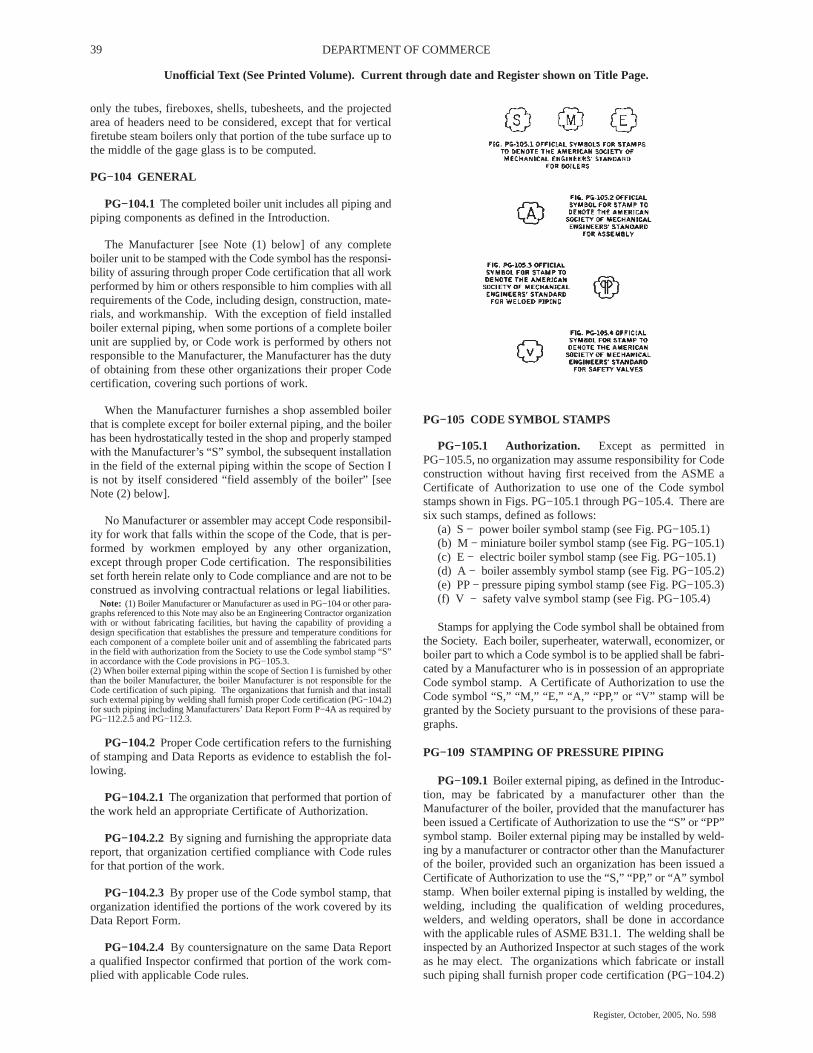
39 DEPARTMENT OF COMMERCE
Unofficial Text (See Printed Volume). Current through date and Register shown on Title Page.
Register, October, 2005, No. 598
only the tubes, fireboxes, shells, tubesheets, and the projectedarea of headers need to be considered, except that for verticalfiretube steam boilers only that portion of the tube surface up tothe middle of the gage glass is to be computed.
PG−104 GENERAL
PG−104.1 The completed boiler unit includes all piping andpiping components as defined in the Introduction.
The Manufacturer [see Note (1) below] of any completeboiler unit to be stamped with the Code symbol has the responsi-bility of assuring through proper Code certification that all workperformed by him or others responsible to him complies with allrequirements of the Code, including design, construction, mate-rials, and workmanship. With the exception of field installedboiler external piping, when some portions of a complete boilerunit are supplied by, or Code work is performed by others notresponsible to the Manufacturer, the Manufacturer has the dutyof obtaining from these other organizations their proper Codecertification, covering such portions of work.
When the Manufacturer furnishes a shop assembled boilerthat is complete except for boiler external piping, and the boilerhas been hydrostatically tested in the shop and properly stampedwith the Manufacturer’s “S” symbol, the subsequent installationin the field of the external piping within the scope of Section Iis not by itself considered “field assembly of the boiler” [seeNote (2) below].
No Manufacturer or assembler may accept Code responsibil-ity for work that falls within the scope of the Code, that is per-formed by workmen employed by any other organization,except through proper Code certification. The responsibilitiesset forth herein relate only to Code compliance and are not to beconstrued as involving contractual relations or legal liabilities.
Note: (1) Boiler Manufacturer or Manufacturer as used in PG−104 or other para-graphs referenced to this Note may also be an Engineering Contractor organizationwith or without fabricating facilities, but having the capability of providing adesign specification that establishes the pressure and temperature conditions foreach component of a complete boiler unit and of assembling the fabricated partsin the field with authorization from the Society to use the Code symbol stamp “S”in accordance with the Code provisions in PG−105.3.(2) When boiler external piping within the scope of Section I is furnished by otherthan the boiler Manufacturer, the boiler Manufacturer is not responsible for theCode certification of such piping. The organizations that furnish and that installsuch external piping by welding shall furnish proper Code certification (PG−104.2)for such piping including Manufacturers’ Data Report Form P−4A as required byPG−112.2.5 and PG−112.3.
PG−104.2 Proper Code certification refers to the furnishingof stamping and Data Reports as evidence to establish the fol-lowing.
PG−104.2.1 The organization that performed that portion ofthe work held an appropriate Certificate of Authorization.
PG−104.2.2 By signing and furnishing the appropriate datareport, that organization certified compliance with Code rulesfor that portion of the work.
PG−104.2.3 By proper use of the Code symbol stamp, thatorganization identified the portions of the work covered by itsData Report Form.
PG−104.2.4 By countersignature on the same Data Reporta qualified Inspector confirmed that portion of the work com-plied with applicable Code rules.
PG−105 CODE SYMBOL STAMPS
PG−105.1 Authorization. Except as permitted inPG−105.5, no organization may assume responsibility for Codeconstruction without having first received from the ASME aCertificate of Authorization to use one of the Code symbolstamps shown in Figs. PG−105.1 through PG−105.4. There aresix such stamps, defined as follows:
(a) S − power boiler symbol stamp (see Fig. PG−105.1)(b) M − miniature boiler symbol stamp (see Fig. PG−105.1)(c) E − electric boiler symbol stamp (see Fig. PG−105.1)(d) A − boiler assembly symbol stamp (see Fig. PG−105.2)(e) PP − pressure piping symbol stamp (see Fig. PG−105.3)(f) V − safety valve symbol stamp (see Fig. PG−105.4)
Stamps for applying the Code symbol shall be obtained fromthe Society. Each boiler, superheater, waterwall, economizer, orboiler part to which a Code symbol is to be applied shall be fabri-cated by a Manufacturer who is in possession of an appropriateCode symbol stamp. A Certificate of Authorization to use theCode symbol “S,” “M,” “E,” “A,” “PP,” or “V” stamp will begranted by the Society pursuant to the provisions of these para-graphs.
PG−109 STAMPING OF PRESSURE PIPING
PG−109.1 Boiler external piping, as defined in the Introduc-tion, may be fabricated by a manufacturer other than theManufacturer of the boiler, provided that the manufacturer hasbeen issued a Certificate of Authorization to use the “S” or “PP”symbol stamp. Boiler external piping may be installed by weld-ing by a manufacturer or contractor other than the Manufacturerof the boiler, provided such an organization has been issued aCertificate of Authorization to use the “S,” “PP,” or “A” symbolstamp. When boiler external piping is installed by welding, thewelding, including the qualification of welding procedures,welders, and welding operators, shall be done in accordancewith the applicable rules of ASME B31.1. The welding shall beinspected by an Authorized Inspector at such stages of the workas he may elect. The organizations which fabricate or installsuch piping shall furnish proper code certification (PG−104.2)
40WISCONSIN ADMINISTRATIVE CODE
Unofficial Text (See Printed Volume). Current through date and Register shown on Title Page.
Register, October, 2005, No. 598
for it including a Manufacturer’s Data Report Form P−4A asrequired by PG−112.2.5 and PG−112.3.
PG−109.2 Welded boiler external piping included within thescope of this Code, over NPS 2 (DN 50), shall be stamped witha Code symbol, together with the manufacturer’s or contractor’sname and serial number. Such stamping shall be on the pipe,valve or fitting adjacent to the welded joint farthest from theboiler. For piping operating at temperatures above 800� F(425�C) the symbol may be stamped on a nameplate that is irre-movably attached by welding, provided such welding is post-weld heat treated, or on a circular metal band at least � in. (6mm) thick. This band around the pipe shall be secured in sucha manner as to prevent it from slipping off during handling andinstallation.
Welded piping NPS 2 (DN 50) or less included within thescope of this Code shall be marked with an identification accept-able to the Inspector and traceable to the required Data Report.Such marking shall be of a type that will remain visible until thepiping has been installed.
PG−109.3 Parts of boilers, such as superheater, waterwall,or economizer headers, or any construction involving onlywelding as covered by PW−41, may be fabricated by a manufac-turer in possession of the pressure piping symbol stamp, and sostamped and reported on a Manufacturer’s Partial Data ReportForm (Form P−4) as called for in PG−112.2.4.
PG−109.4 Mechanically assembled boiler external pipingwhich contains no pressure boundary welds does not requirestamping, and as such may be assembled by a non−stamp holder.Note that the responsibility for documentation and hydrostatictesting of a mechanically assembled boiler external piping mustbe assumed by a holder of a valid “S,” “A,” or “PP” stamp (seePG−112.2.5).
PG−110 STAMPING OF SAFETY VALVES
Each safety valve shall be plainly marked with the requireddata by the Manufacturer or Assembler (see PG−73.3.4) in sucha way that the marking will not be obliterated in service. Themarking shall be placed on the valve or on a nameplate securelyfastened to the valve. The Code “V” symbol shall be stampedon the valve or nameplate by the Manufacturer or Assembler, asapplicable. The other required data may be stamped, etched,impressed, or cast on the valve or nameplate. The marking shallinclude the following:
(a) the name (or an acceptable abbreviation) of the Manufac-turer and Assembler, as applicable
(b) Manufacturer’s design or type number
(c) NPS (DN) (the nominal pipe size of the valve inlet)
(d) set pressure____psi (MPa)
(e) Capacity
(1) capacity____lb/hr (kg/hr) (for saturated steam servicein accordance with PG−69.2 and with the valve adjusted forblowdown permitted by PG−72); or
(2) capacity____lb/hr (kg/hr) at ______�F (�C) (forsuperheated steam service in accordance with PG−68.7 andwith the valve adjusted for blowdown permitted by PG−72).
(f) year built, or alternatively, a coding may be marked on thevalve such that the valve Manufacturer or Assembler can iden-tify the year the valve was assembled and tested
(g) ASME symbol as shown in Fig. PG−105.4
PG−111 LOCATION OF STAMPINGS
The location of the required stampings shall be as listedbelow. These stampings shall be left uncovered or an easilyremovable marked cover may be provided over the stampingwhen a boiler is covered with insulation, or jacketed. No piping,boiler appliance, or other obstructions shall interfere with read-ing of the stamping.
PG−111.1 Horizontal−return tubular boilers – on the fronthead above the central rows of tubes.
PG−111.2 Horizontal−flue boilers – on the front head abovethe flues.
PG−111.3 Traction, portable, or stationary boilers of thelocomotive type or Star watertube boilers – on the furnace endabove the handhole. Or on traction boilers of the locomotivetype – on the left wrapper sheet forward of the driving wheel.
PG−111.4 Vertical firetube and vertical submerged tube boil-ers – on the shell above the firedoor and handhole opening.
PG−111.5 Watertube Boilers
PG−111.5.1 Drum type – on a head of the steam outlet drumnear and above the manhole.
PG−111.5.2 Forced−flow steam generator with no fixedsteam and waterline – the master stamping (PG−106.3) shall belocated on a major pressure part, located near the main operatingfloor where readily visible. The Data Report Form shall recordthe location of the master stamping.
PG−111.6 Scotch marine boilers – on either side of the shellnear the normal water level line and as near as practical to thefront tubesheet.
PG−111.7 Economic boilers – on the front head, above thecenter row of tubes.
PG−111.8 Miniature and electric boilers – on some conspic-uous and accessible place on the boiler proper, or on a stampingplate at least 3/64 in. (1.2 mm) thick, permanently fastened(adhesives prohibited) to the boiler.
PG−111.9 On any of the above types where there is not suffi-cient space in the place designated, and for other types and newdesigns – in a conspicuous place on the boiler proper. The DataReport Form shall record the location of the required stamping.
PG−111.10 Superheaters – on superheater header near theoutlet. Other headers shall carry identifying marks.
PG−111.11 Economizers – at a handy location on water inletheader or drums. Other headers shall carry identifying marks.
PG−111.12 Waterwalls – on one end of a lower header. Otherheaders shall carry identifying marks.
PG−111.13 When required by PG−106.6 and PG−106.7, theManufacturer [see PG−104, Note (1)] shall furnish a nameplateor plates on which the appropriate Code Symbol and design data

41 DEPARTMENT OF COMMERCE
Unofficial Text (See Printed Volume). Current through date and Register shown on Title Page.
Register, October, 2005, No. 598
for the scope of his responsibility are permanently imprinted.The nameplate shall be securely attached to the front of theboiler, its setting or casing, at a place readily visible from theoperating floor or platform.
PG−112 MANUFACTURERS’ DATA REPORT FORMS
PG−112.1 Ten types of Manufacturers’ Data Report Formsare shown in the Appendix under the heading “Data ReportForms and Guides” at the end of this Section. These forms shallbe used by the Manufacturer [see PG−104, Note (1)] to recordall the items of a complete boiler unit, in accordance with theprovisions of PG−112.2. When the certification of the completeboiler unit is accomplished by more than one Data Report, theprincipal Data Report (P−2, P−2A, P−3, or P−3A) shall be desig-nated as the Master Data Report (see PG−113).
For forced−flow steam generators with no fixed steam andwaterline consisting of groups of pressure parts or componentsdesigned at several different pressure levels, a separateManufacturers’ Data Report shall clearly identify the pressureparts at each pressure level and show the maximum allowableworking pressure. These several Data Reports shall be attachedto a Master Data Report (PG−113) that shall clearly identify eachcomponent as part of the complete unit.
PG−112.2 Types of Data Report Forms. The types of DataReport Forms and the purposes for which they are to be used arespecified in PG−112.2.1 through PG−112.2.8.
PG−112.2.1 Form P−2, Manufacturers’ Data Report for AllTypes of Boilers Except Watertube and Electric, shall be used torecord all types of boilers other than watertube boiler units andparts thereof, which are included under Form P−3.
PG−112.2.1.1 Form P−2A, Manufacturers’ Data Report forAll Types of Electric Boilers, shall be used to record all types ofelectric boilers.
PG−112.2.1.2 Form P−2B, Manufacturers’ Data Report forElectric Superheaters and Reheaters, shall be used to recordelectric superheaters and reheaters installed external to theboiler setting.
PG−112.2.2 Form P−3, Manufacturers’ Data Report forWatertube Boilers, Superheaters (except electric), Waterwalls,and Economizers, shall be used to record all of the items com-prising a watertube boiler.
The Form P−3 shall also be used to record a superheater,waterwall, or economizer when the design of such an item is cer-tified by a manufacturer other than the boiler Manufacturer, orwhen such an item is to be added to an existing boiler. The itemshall be stamped with the ASME “S” symbol and the additionalinformation, as applicable, shown in PG−106.4.2.
Item 10 on Form P−3 shall be used to record other parts con-nected at the openings listed in Item 11 if such parts are fabri-cated of materials or by processes that require Code inspection.If such parts have not been connected prior to the hydrostatictest, a notation shall be made under Item 10 reading: “No partsconnected to the openings listed in Item 11 except as noted.”
PG−112.2.3 Form P−3A, Engineering−Contractor DataReport for a Complete Boiler Unit, shall be used when such anorganization assumes the Manufacturer’s Code responsibility as
provided for by PG−104, Note (1). This form shall be used tocertify Code responsibility for the design specification of thecomplete boiler unit, of which the components are individuallycertified by their individual manufacturers in accordance withthe Code rules. This form also provides for field assembly certi-fication.
PG−112.2.4 Form P−4, Manufacturer’s Partial Data Report,shall be used to record boiler parts requiring inspection andstamping under this Section which are furnished by other thanthe Manufacturer responsible for the completed boiler, super-heater, waterwall, or economizer.
(a) Except as provided in PG−112.2.4(b), Form P−4 shall beused only to provide supporting data for the information givenon the Master Data Report (see PG−113) or on the Form P−3used to record a superheater, waterwall, or economizer.
(b) When used to record parts furnished to the user of anexisting boiler as replacement or repair parts, Form P−4 is suffi-cient and need not support a Master Data Report. A copy of theparts Manufacturers’ Form P−4 shall be forwarded to the pur-chaser.
(c) The parts manufacturer shall indicate under “remarks”the extent to which he has performed the design functions.When the parts manufacturer performed only a portion of thedesign, he shall state which portion of the design he has per-formed.
PG−112.2.5 Form P−4A, Manufacturers’ Data Report forFabricated Piping, shall be used to record all shop or field−welded piping that falls within the scope of this Section but is notfurnished by the boiler Manufacturer. Form P−4B, Manufactur-ers’ Data Report for Field Installed Mechanically AssembledPiping, shall be used to record all field installed mechanicallyassembled boiler external piping. Form P−4B shall be used onlyfor piping that contains no joints brazed or welded by the fieldinstaller.
PART PFTREQUIREMENTS FOR FIRETUBE BOILERS
GENERAL
PFT−1 GENERAL
The rules in Part PFT are applicable to firetube boilers andparts thereof and shall be used in conjunction with the generalrequirements in Part PG as well as with the specific requirementsin the applicable Parts of this Section that apply to the methodof fabrication used.
MATERIALS
PFT−5 GENERAL
PFT−5.1 Materials used in the construction of pressure partsfor firetube boilers shall conform to one of the specificationsgiven in Section II and shall be limited to those for which allow-able stress values are given in Tables 1A and 1B of Section II,Part D, or as otherwise specifically permitted in Parts PG andPFT.
PFT−5.2 Waterleg and doorframe rings of vertical firetubeboilers and of locomotive and other type boilers shall be ofwrought iron or steel, or cast steel as designated in the SA−216.

42WISCONSIN ADMINISTRATIVE CODE
Unofficial Text (See Printed Volume). Current through date and Register shown on Title Page.
Register, October, 2005, No. 598
The ogee or other flanged construction may be used as a substi-tute in any case.
DESIGN
PFT−8 GENERAL
The rules in the following paragraphs apply specifically tothe design of firetube boilers and parts thereof and shall be usedin conjunction with the general requirements for design in PartPG as well as with the specific requirements for design in theapplicable Parts of this Section that apply to the method of fab-rication used.
PFT−9 THICKNESS REQUIREMENTS
PFT−9.1 Shell and Dome. The thickness after forming shallbe as determined in accordance with the rules in Part PG but shallbe not less than the values shown in the following table.
Inside Diameter of Shell orDome, in. (mm)
Minimum Thickness,in. (mm)
36 (900) or under � (6)Over 36 (900) to 54 (1 350) 5/16 (8)Over 54 (1 350) to 72 (1 800) 3/8 (10)Over 72 (1 800) � (13)
PFT−9.2 Tubesheet
PFT−9.2.1 The thickness shall be as determined in accord-ance with Part PG and Part PFT but shall not be less than the val-ues given in the following table:
Inside Diameter of Shell, in.(mm)
Minimum Thickness,in. (mm)
42 (1 100) or under 3/8 (10)Over 42 (1 100) to 54 (1 350) 7/16 (11)Over 54 (1 350) to 72 (1 800) � (13)Over 72 (1 800) 9/16 (14)
PFT−9.2.2 When buttwelded to the shell of a firetube boiler,a formed tubesheet with a straight flange longer than 1 � timesthe tubesheet thickness shall have a straight flange thickness notless than that specified in the table in PFT−9.2.1, but in no caseless than 0.75 times the thickness of the shell to which it isattached.
PFT−10 SHELL JOINTS
Longitudinal and circumferential welded joints of a shell ordrum shall comply with the rules in Part PW.
PFT−11 ATTACHMENT OF HEADS AND TUBESHEETS
Flat heads and tubesheets of firetube boilers shall be attachedby one of the following methods.
PFT−11.2 By flanging and butt welding in accordance withParts PG and PW.
PFT−11.3 By attaching an outwardly or inwardly flangedtubesheet to the shell by fillet welding provided the followingrequirements are met.
PFT−11.3.1 The tubesheet is supported by tubes, or stays, orboth.
PFT−11.3.2 The joint attaching an outwardly flanged tube-sheet is wholly within the shell and forms no part thereof.
PFT−11.3.3 Inwardly flanged tubesheets are full filletwelded inside and outside.
PFT−11.3.4 The throat dimension of the full fillet weld isequal to not less than 0.7 of the thickness of the head.
PFT−11.3.5 The shell at the welds is not in contact with pri-mary furnace gases.1
1 Primary furnace gases are those in a zone where the design temperature of
those gases exceeds 850� F (455� C).
PFT−11.3.6 The construction conforms in all other respectsto the requirements of this Section, including welding and post-weld heat treating, except that radiographic examination is notrequired.
PFT−11.3.7 This construction shall not be used on the rearhead of a horizontal−return tubular boiler and inwardly flangedtubesheets shall not be used on a boiler with an extended shell.
PFT−11.3.8 On inwardly flanged tubesheets, the length offlange shall conform to the requirements of PW−13 and the dis-tance of the outside fillet weld to the point of tangency of theknuckle radius shall be not less than � in. (6 mm).
PFT−11.4 By attaching an unflanged tubesheet to the shellby welding, provided the requirements of PFT−11.4.1 throughPFT−11.4.7 are met.
PFT−11.4.1 The tubesheet is supported by tubes, or stays, orboth.
PFT−11.4.2 The welded joint may be made through the tube-sheet or shell thickness. When the weld joint is made throughthe shell, a minimum of 80% of the pressure load shall be carriedby the tubes, stays, or both.
PFT−11.4.3 The weld is a full penetration weld equal at leastto the full thickness of the base metal applied from either or bothsides. When the full penetration weld is made through the shell,an external fillet weld with a minimum throat of � in. (6mm)shall be provided, and no weld prep machining shall be per-formed on the flat tubesheet. The distance from the edge of thecompleted weld to the peripheral edge of the tubesheet shall notbe less than the thickness of the tubesheet.
PFT−11.4.4 The shell or wrapper sheet, where exposed toprimary furnace gases1 and not water cooled, does not extendmore than 1/8 in. (3 mm) beyond the outside face of the tube-sheet.
PFT−11.4.5 The weld attaching a furnace or a lower tube-sheet of a vertical firetube boiler to the furnace sheet is whollywithin the furnace sheet and is ground flush with the upper orwater side of the tubesheet.
PFT−11.4.6 The construction conforms in all other aspectsto the requirements of this Section including welding, and post-weld heat treatment, except that radiographic examination is notrequired.
PFT−11.4.7 This construction shall not be used on the rearhead of a horizontal−return tubular boiler.

43 DEPARTMENT OF COMMERCE
Unofficial Text (See Printed Volume). Current through date and Register shown on Title Page.
Register, October, 2005, No. 598
PFT−12 TUBES
PFT−12.1 Allowable Working Pressure
PFT−12.1.1 The maximum allowable working pressure oftubes or flues of firetube boilers shall be as given in PFT−50 andPFT−51.
PFT−12.1.2 The maximum allowable working pressure forcopper tubes or nipples subjected to internal or external pressureshall not exceed 250 psi (1.7 MPa). The maximum temperatureshall not exceed 406� F (208� C).
The maximum allowable working pressure for copper cladtubes subjected to external pressure shall be determined by theformula in PFT−51, in which t may be increased by one−half thethickness of the cladding.
PFT−12.2 Attachment of Tubes
PFT−12.2.1 Figure PFT−12.1 illustrates some of the accept-able types of tube attachments. Such connections shall be:
(a) expanded and beaded as in illustrations (a), (b), and (d)
(b) expanded and beaded and seal welded as in illustration(c)
(c) expanded and seal welded as in illustration (e)
(d) welded, as in illustrations (f) and (g).
Tube ends attached by expanding and welding are subject tothe provisions specified in PFT−12.2.1.1 through PFT−12.2.1.3.
PFT−12.2.1.1 Where no bevel or recess is employed, thetube shall extend beyond the tubesheet not less than a distanceequal to the tube thickness or 1/8 in. (3 mm), whichever is thegreater, nor more than twice the tube thickness or � in. (6 mm),whichever is the lesser [see Fig. PFT−12.1, illustration (e)].
PFT−12.2.1.2 The tubesheet hole may be beveled orrecessed. The depth of any bevel or recess shall not be less thanthe tube thickness or 1/8 in. (3 mm), whichever is greater, normore than one−third of the tubesheet thickness, except that whentube thicknesses are equal to or greater than 0.150 in. (4 mm),the bevel or recess may exceed T/3. Where the hole is beveledor recessed, the projection of the tube beyond the tubesheet shallnot exceed a distance equal to the tube wall thickness [see Fig.PFT−12.1, illustrations (f) and (g)].
PFT−12.2.1.3 On types of welded attachment shown in Fig.PFT−12.1, illustrations (c) and (e), the tubes shall be expandedbefore and after welding. On types shown in illustrations (f) and(g), the tubes may be expanded.
PFT−12.2.2 Expanding of tubes by the Prosser method maybe employed in combination with any beaded or seal weldedattachment method [see Fig. PFT−12.1, illustration (b)].
PFT−12.2.3 After seal welding as shown by Fig. PFT−12.1,illustrations (c) and (e), a single hydrostatic test of the boilershall suffice.
PFT−12.2.4 The inner surface of the tube hole in any formof attachment may be grooved or chamfered.
PFT−12.2.5 The sharp edges of tube holes shall be taken offon both sides of the plate with a file or other tool.
Note: (1) Not less than t or 1/8 in. (3 mm), whichever is the greater, nor morethan 2t or � in. (6 mm), whichever is the lesser.
(2) Not less than t or 1/8 in. (3 mm), whichever is the greater, nor more than T/3(see PFT−12.2.1.2).
(3) Not more than t.(4) Not less than t or 1/8 in. (3 mm), whichever is the greater, nor more than T/3
(see PFT−12.2.1.2).
FIG. PFT−12.1 SOME ACCEPTABLE FORMS OF TUBEATTACHMENT ON FIRETUBE BOILERS
DOORS AND OPENINGS
PFT−40 WELDED DOOR OPENINGS
Arc or gas welding may be used in the fabrication of doorholes provided the sheets are stayed around the opening inaccordance with the requirements of PFT−27.6 and PFT−27.7.
The fit−up of the several parts of an arc or gas welded dooropening shall be such that the maximum gap between the twoplates to be joined by welding does not exceed 1/8 in. (3 mm).
PFT−41 OPENINGS IN WRAPPER SHEETS

44WISCONSIN ADMINISTRATIVE CODE
Unofficial Text (See Printed Volume). Current through date and Register shown on Title Page.
Register, October, 2005, No. 598
Openings located in the curved portion of the wrapper sheetof a locomotive type boiler shall be designed in accordance withthe rules in PG−32.
PFT−42 FIRESIDE ACCESS OPENINGS
The minimum size of an access or fire door opening, in whichthe minimum furnace dimension is 24 in. (600 mm), shall be notless than 12 in. x 16 in. (300 mm x 400 mm) or equivalent area,11 in. (280 mm) to be the least dimension in any case. A circularopening shall be not less than 15 in. (380 mm) in diameter.
For furnace dimensions less than 24 in. (600 mm), the open-ing should be 2 � in. x 3 � in. (70 mm x 89 mm) or larger wherepossible. In cases where the size or shape of the boiler prohibitsan opening of that size, two openings with a minimum size of 1in. (25 mm) may be used, preferably opposite each other, to per-mit inspection and cleaning of the furnace. If the burner isremovable so as to permit inspection and cleaning through theburner opening, a separate access opening need not be provided.
The bonnet or smoke hood of a vertical flue or tubular boilershall be provided with an access opening at least 6 in. x 8 in. (150mm x 200 mm) for the purpose of inspection and cleaning thetop head of the boiler.
PFT−43 REQUIREMENTS FOR INSPECTION OPEN-INGS
PFT−43.1 All openings shall meet the requirements ofPG−32 through PG−44. Manholes may be substituted for hand-holes. Where washout plugs are used the minimum size shall be1 � in. (38 mm).
PFT−43.2 Horizontal−Return Tubular Boiler. A manholeshall be provided in the front head below the tubes. On boilersless than 48 in. (1 200 mm) in inside diameter a handhole maybe used in lieu of the manhole. A manhole shall be provided inthe upper part of the shell or head. On boilers 40 in. (1 000 mm)and under in inside diameter a handhole may be used in lieu ofthe manhole.
PFT−43.3 Traction, Stationary, or Portable Return TubeFiretube Boilers. Handholes or washout plugs, not less thansix, shall be located as follows: one in the rear head below thetubes; four in the lower part of the waterleg, with one near thethroat sheet when possible; one in the front head at the line of thecrown sheet, except when the location would lie within a smokebox the handhole or washout plug shall be located on a sidesheet.
Horizontal firetube boilers shall also have a manhole locatedabove the tubes on the head or shell, except that on boilers 48 in.(1 200 mm) and under in inside diameter a handhole may be usedin lieu of the manhole.
PFT−43.4 Scotch Boilers. Handholes or washout plugs, notless than four, shall be located as follows: one on the bottom ofthe shell; one above the furnace; one on each side of the fronthead or shell below the tubes and near the front head.
A manhole shall also be provided on the head or shell abovethe tubes, except on boilers 48 in. (1 200 mm) and under in insidediameter a handhole may be used in lieu of the manhole.
Scotch marine boilers (wet−back type) shall also have anopening for inspection of the water space at the rear of the com-bustion chamber.
PFT−43.5 Vertical Boilers
PFT−43.5.1 For sizes over 24 in. (600 mm) in outside diame-ter the following handholes, not less than four, shall be provided:one at or about the waterline (or opposite the fusible plug whenused); three at or about the line of the lower tubesheet.
On internally fired types, three additional handholes shall beprovided at the lowest part of the waterleg.
On flueless types, three handholes shall be provided at thebottom of the waterleg in lieu of the three required above.
On submerged tube types, two additional handholes shall beprovided in line with the underside of the upper tubesheet.
PFT−43.5.2 For sizes less than or equal to 24 in. (600 mm)in outside diameter, the following inspection openings, not lessthan three, shall be provided in the shell: one handhole at thewaterline; two washout plugs near the bottom (the blowoffopening shall not be considered in lieu of this requirement).
On internally fired types, a handhole shall be provided in linewith the lower tubesheet, in which case the handhole at thewaterline may be omitted.
On flueless types, one additional washout plug shall be pro-vided above and adjacent to the firing door.
On submerged tube types, a handhole shall also be providedin line with the upper tubesheet.
PFT−44 OPENING BETWEEN BOILER AND SAFETYVALVE
The opening or connection between the boiler and the safetyvalve shall have at least the area of the valve inlet.
After the boiler Manufacturer provides for the openingrequired by the Code, a bushing may be inserted in the openingin the shell to suit a safety valve that will have the capacity torelieve all the steam that can be generated in the boiler and whichwill meet the Code requirements.
No valve of any description shall be placed between therequired safety valve or safety relief valve or valves and theboiler, or on the discharge pipe between the safety valve orsafety relief valve and the atmosphere. When a discharge pipeis used, the cross−sectional area shall be not less than the fullarea of the valve outlet or of the total of the areas of the valveoutlets discharging there into and shall be as short and straightas possible and so arranged as to avoid undue stresses on thevalve or valves.
DOMES
PFT−45 REQUIREMENTS FOR DOMES
PFT−45.1 The longitudinal joint of a dome may be buttwelded or the dome may be made without a seam of one pieceof steel pressed into shape. The dome flange may be double fullfillet lap−welded to the shell if all welding complies fully withthe requirements for welding in Part PW. Radiographic

45 DEPARTMENT OF COMMERCE
Unofficial Text (See Printed Volume). Current through date and Register shown on Title Page.
Register, October, 2005, No. 598
examination of the fillet welds may be omitted. The openingshall be reinforced in accordance with PG−32 through PG−44.
PFT−45.3 When a dome is located on the barrel of a locomo-tive−type boiler or on the shell of a horizontal−return tubularboiler, the outside diameter of the dome shall not exceed six−tenths the inside diameter of the shell or barrel of the boilerunless the portion of the barrel or shell under the dome (the neu-tral sheet) is stayed to the head or shell of the dome by stayswhich conform in spacing and size to the requirements given inPG−46 and Table 1A of Section II, Part D. With such stayedconstruction the outside diameter of a dome located on the barrelor shell of a boiler is limited to eight−tenths of the barrel or shellinside diameter.
PFT−45.4 All domes shall be so arranged that any water candrain back into the boiler.
PFT−45.5 Flanges of domes shall be formed with a cornerradius, measured on the inside, of at least twice the thickness ofthe plate for plates 1 in. (25 mm) in thickness or less, and at leastthree times the thickness of the plate for plates over 1 in. (25 mm)in thickness.
PFT−45.6 Domes and manhole frames attached to shells orheads of boilers shall be designed in accordance with PG−32through PG−44.
PFT−45.7 In a locomotive−type boiler with a dome on atapered course, the maximum allowable diameter of the domeshall be based on that diameter of the tapered course which inter-sects the axis or center line of the dome.
PART PEBREQUIREMENTS FOR ELECTRIC BOILERS
GENERAL
PEB−1 GENERAL
The rules in Part PEB are applicable to electric boilers andparts thereof and shall be used in conjunction with the generalrequirements in Part PG as well as with the special requirementsin the applicable Parts of this Section that apply to the methodof fabrication used.
PEB−2 SCOPE
PEB−2.1 This part contains special rules for construction ofelectric boilers, both of the electrode and immersion resistanceelement type. This Part does not include electric boilers wherethe heat is applied externally to the boiler pressure vessel byelectric resistance heating elements, induction coils, or otherelectrical means. These types of electric boilers shall be con-structed in accordance with other applicable Parts of this Sec-tion.
PEB−2.2 Electric boilers and parts thereof that do not exceedthe diameter, volume, or pressure limits of PMB−2 may be con-structed using the applicable paragraphs of Part PMB in con-junction with this Part.
PEB−2.3 An electrode type boiler is defined as an electricboiler in which heat is generated by the passage of an electriccurrent using water as the conductor.
PEB−2.4 An immersion resistance element type boiler isdefined as an electric boiler in which heat is generated by the
passage of an electric current through a resistance heating ele-ment immersed in water.
PEB−3 OPTIONAL REQUIREMENTS FOR THEBOILER PRESSURE VESSEL
The boiler pressure vessel may be constructed in compliancewith the ASME Pressure Vessel Code Section VIII, Division 1,rules for unfired steam boilers [UW−2(c)] subject to the condi-tions specified in PEB−3.1 through PEB−3.4.
PEB−3.1 The Manufacturer who certifies and stamps thecompleted boiler shall specify to the “U” stamp holder all addi-tional requirements of Part PEB, which are not requirements ofSection VIII, Division 1, and shall ensure that these require-ments are satisfied.
PEB−3.2 These additional requirements are:
PEB−3.2.1 The materials of construction shall comply withthe requirements of PEB−5.1 and PEB−5.3.
PEB−3.2.2 Inspection openings shall comply with therequirements of PEB−10.
PEB−3.3 The boiler pressure vessel shall be stamped withthe ASME Code “U” symbol and the letters “UB,” and be docu-mented with the ASME U−1 or U−1A Data Report.
PEB−3.4 The master Data Report P−2A for the ElectricBoiler shall indicate “Boiler pressure vessel constructed to Sec-tion VIII, Division 1 as permitted by Part PEB.”
MATERIALS
PEB−5 GENERAL
PEB−5.1 Unless specifically permitted elsewhere in this sec-tion, materials used in the construction of pressure parts for elec-tric boilers shall conform to one of the specifications in SectionII and shall be limited to those permitted by PG−6, PG−7, PG−8,and PG−9 for which allowable stress values are given in Tables1A and 1B of Section II, Part D. Miscellaneous pressure partsshall conform to the requirements of PG−11.
PEB−5.2 Seamless or welded shells, plates, or heads of elec-tric boilers shall not be less than 3/16 in. (5 mm) in thickness.
PEB−5.3 Electric boilers of the immersion element type maybe fabricated of austenitic stainless steel type 304, 304L, 316,316L, and 347 of any material specification listed in PG−6 andPG−9, provided that a precautionary statement indicating thatthe boiler shall be operated using only deionized water, havinga maximum conductance of 1 microSiemen per cm (1 µS/cm)[minimum specific resistivity of 1 megohm per cm (1M�/cm)], is clearly marked on the boiler in a visible location.
DESIGN
PEB−8 GENERAL
PEB−8.1 The rules in the following paragraphs apply specif-ically to the design of electric boilers and parts thereof. Theyshall be used in conjunction with the general requirements fordesign in Part PG, any applicable requirements in Part PMB forminiature boilers, and with the specific requirements for designin applicable Parts of this Section that apply to the method of fab-rication used.

46WISCONSIN ADMINISTRATIVE CODE
Unofficial Text (See Printed Volume). Current through date and Register shown on Title Page.
Register, October, 2005, No. 598
PEB−8.2 Responsibility of design of electric boilers to bemarked with the “E” symbol shall be that of the holder of the “E”stamp.
PEB−9 WELDING
Electric boilers may be constructed by fusion welding inaccordance with all the requirements of this Section except thatpostweld heat treatment, radiography of the welded joints, andthe nondestructive examinations described in PG−93.1 are notrequired when the limitations in PMB−2.1 are not exceeded.
PEB−10 INSPECTION OPENINGS
PEB−10.1 Electric boilers of a design employing a remov-able cover, or removable internal electric heating elements thatwill permit access for inspection, and cleaning and having aninternal volume (exclusive of casing and insulation) of not morethan 5 ft3 (0.14 m3) need not be fitted with washout or inspectionopenings.
PEB−10.2 Electric boilers of more than 5 ft3 (0.14 m3) notprovided with a manhole, shall have an inspection opening orhandhole located in the lower portion of the shell or head. Theinspection opening shall not be smaller than NPS 3 (DN 80). Inaddition, electric boilers of the resistance heating element typedesigned for steam service shall have an inspection opening orhandhole at or near the normal waterline.
PEB−11 FEEDWATER SUPPLY
PEB−11.1 The feedwater source to electric boilers shall becapable of meeting the applicable requirements of PG−61.Feedwater connections to an electric boiler shall not be smallerthan NPS � (DN 15), except as permitted by PMB−11.
PEB−11.2 Electric boilers that do not exceed the diameter,volume, or pressure limits of PMB−2, may have the feedwaterdelivered through the blowoff opening if desired.
PEB−12 BLOWOFF
PEB−12.1 The blowoff piping for each electric boiler pres-sure vessel having a normal water content not exceeding 100 gal(380 L) is required to extend through only one valve.
PEB−12.2 The minimum size of blowoff pipes and fittingsshall be NPS 1 (DN 25), except that for boilers of 200 kW inputor less the minimum size of pipe and fittings may be NPS � (DN20). Electric boilers that do not exceed the diameter, volume, orpressure limits of PMB−2 may have blowoff connections inaccordance with PMB−12.
PEB−13 WATER LEVEL INDICATORS
PEB−13.1 Electric boilers of the electrode type shall have atleast one gage glass. The gage glass shall be located as to indi-cate the water levels both at startup and under maximum steamload conditions as established by the Manufacturer.
PEB−13.2 Electric boilers of the resistance element typeshall have at least one gage glass. The lowest visible water levelin the gage glass shall be at least 1 in. (25 mm) above the lowestpermissible water level as determined by the Manufacturer.Each electric boiler of this type shall also be equipped with anautomatic low−water cutoff on each boiler pressure vessel solocated as to automatically cut off the power supply to the heat-
ing elements before the surface of the water falls below the vis-ible level in the gage glass.
PEB−13.3 Tubular gage glasses on electric boilers shall beequipped with protective rods or shields.
PEB−14 PRESSURE GAGES
Pressure gages shall meet the requirements of PG−60.6.
PEB−15 SAFETY VALVES
PEB−15.1 Each electric boiler shall have at least one safetyvalve or safety relief valve. Electric boilers with a power inputmore than 1,100 kW shall have two or more safety valves orsafety relief valves.
PEB−15.2 The minimum safety valve or safety relief valverelieving capacity for electric boilers shall be 3 � lb/hr/kW (1.6kg/hr/kW) input. The pressure setting shall not be higher thanthe MAWP stamped on the completed boiler (see PEB−18.3.2).
PEB−16 AUTOMATIC DEVICES
Electric boilers shall be provided with pressure and/or tem-perature controls and an automatic low−water fuel cutoff. Nolow−water cutoff is required for electrode type boilers.
PEB−17 HYDROSTATIC TEST
PEB−17.1 Each electric boiler pressure vessel shall behydrostatically tested at completion of fabrication in accordancewith PG−99 or PMB−21, as applicable.
PEB−17.2 In addition to the above, after assembly of theboiler pressure vessel and the mechanically assembled boilerexternal piping and trim, the completed electric boiler shall begiven a final hydrostatic test at a pressure not less than 1 � timesthe MAWP of the pressure vessel. Miniature electric boilers thatare trimmed to operate at less than the MAWP of the pressurevessel shall be given a hydrostatic test at a pressure not less thanthe safety valve setting.
PEB−17.3 When the electric boiler is to be marked with the“E” symbol, the symbol shall be applied after completion of thehydrostatic test of PEB−17.2.
PEB−18 INSPECTION AND STAMPING OF BOILERS
PEB−18.1 Inspection of electric boilers shall be as requiredby PG−90.1 and PG−90.3. Witness by the Authorized Inspectorof the hydrotest required in PEB−17.2 for the completed boilermay be omitted for electric boilers that meet all the followinglimitations:
(a) 800 kW maximum per vessel
(b) 600 V maximum
(c) mechanically assembled boiler external piping (BEP)only
When the Authorized Inspector does not perform a finalinspection of the completed boiler, the Manufacturer or Assem-bler shall make an equivalent examination. The equivalentexamination shall be in accordance with a quality control proce-dure meeting the requirements of PEB−18.2 and PEB−18.5.
PEB−18.1.1 Electric boilers exceeding the size limitationsspecified in PEB−18.1, and having only mechanically

47 DEPARTMENT OF COMMERCE
Unofficial Text (See Printed Volume). Current through date and Register shown on Title Page.
Register, October, 2005, No. 598
assembled external piping (BEP) and trim, shall have a finalinspection by the Authorized Inspector, who shall also witnessthe hydrostatic test called for in PEB−17.2.
PEB−18.1.2 For electric boilers having welded or brazedboiler external piping (BEP) or trim, the inspection require-ments of PG−90.1 and the hydrostatic test requirements ofPG−99 apply.
PEB−18.2 Each electric boiler Manufacturer shall complywith the applicable requirements of PG−104 and PG−105.
PEB−18.2.1 An electric boiler Manufacturer or Assemblerapplying for or renewing the “E” stamp shall have its facilitiesand organizations subject to a joint review by its AuthorizedInspection Agency and the legal jurisdiction involved (see lastparagraph of PG−105.4).
PEB−18.2.2 A Manufacturer or Assembler holding an “E”stamp and assembling units where the final shop inspection isnot mandatory (see PEB−18.1), shall be subject to periodicreview by its Authorized Inspection Agency. The review shallbe conducted on a quarterly basis or more frequently if deemednecessary by the Authorized Inspection Agency. The frequencyof this review may be reduced subject to written agreementbetween the Manufacturer or Assembler and its inspectionagency and the written approval of the appropriate legal jurisdic-tion. However, in no case shall the review be less than onceevery 6 months.
PEB−18.3 The stamping of electric boilers shall conform tothe requirements of PG−106. Completed electric boilers shall bemarked with the “S” or “M” symbol by the Manufacturer of theboiler pressure vessel except when the boiler pressure vessel isconstructed under the provisions of PEB−3 (see PEB−18.4).When the trim, fixtures and fittings (such as valves), threadedboiler external piping, and appurtenances are connected to anelectric boiler by a Manufacturer or Assembler not authorizedto apply the “S” or “M” stamp, the boiler assembler shall applyan “E” stamp to the completed assembly. “E” stamp holders arelimited to the use of assembly methods that do not require weld-ing or brazing.
PEB−18.3.1 The stamping of the boiler pressure vessel shallbe located as called for in PG−111.8 and need not indicate thekW input or the maximum designed steaming capacity.
PEB−18.3.2 The stamping of the complete electric boilershall be on a separate metallic plate and shall be in accordancewith PG−106.4. The MAWP shall be that established by thecompleted boiler assembler holding the “S,” “M,” or “E” stamp,but in no case higher than the MAWP stamped on the boilershell. The MAWP shall be listed on Part II of Form P−2A,Manufacturers’ Data Report for All Types of Electric Boilers.This plate shall be located on the assembly so that it is readilyvisible from the operating floor.
PEB−18.3.3 The stamping required by PEB−18.3.2 need notbe done in the presence of the Authorized Inspector for electric
boilers that do not receive final inspection by the AuthorizedInspector (see PEB−18.1).
PEB−18.4 For boiler pressure vessels constructed under theprovisions of PEB−3, the inspection and stamping requirementsof Section VIII, Division 1, UG−116(c) for special service pres-sure vessels (UB), shall be followed.
PEB−18.5 Those Manufacturers and Assemblers providingan equivalent examination of completed electric boilers whenfinal inspection is not witnessed by the Authorized Inspector(see PEB−18.1), shall provide oversight by a Certified Individ-ual (CI).
PEB−18.5.1 A Certified Individual (CI) shall be anemployee of the Manufacturer or Assembler and shall be quali-fied and certified by the Manufacturer or Assembler. Qualifica-tions shall include as a minimum
(a) knowledge of the requirements of this Section for theapplication of Code symbols
(b) knowledge of the Manufacturer’s quality program
(c) training commensurate with the scope, complexity, orspecial nature of the activities to which oversight is to be pro-vided
The Manufacturer or Assembler shall maintain a record con-taining objective evidence of the Certified Individual’s qualifi-cations, training and certification.
PEB−18.5.2 The duties of a Certified Individual (CI) shallbe to assure that each use of the Code symbol as permitted inPEB−18.3.3 is in accordance with the requirements of this Sec-tion and is documented on the Certificate of Conformance onForm P−2A, Manufacturers’ Data Report for All Types of Elec-tric Boilers. The CI shall also
(a) verify that each electric boiler, to which a Code symbolis applied, meets all applicable requirements of this Section
(b) sign the Certificate of Conformance, Form P−2A, priorto release of control of the boiler
PEB−19 MANUFACTURERS’ DATA REPORT FORELECTRIC BOILERS
PEB−19.1 This form consists of two parts. Part I is to becompleted by the Manufacturer of the boiler pressure vessel whois the holder of the “S” or “M” stamp and his inspection agency.Part II is to be completed by the Manufacturer or Assemblerresponsible for the completed electric boiler who shall be autho-rized to use any of the “S,” “M,” or “E” stamps.
PEB−19.2 When the boiler pressure vessel is constructed bya “U” stamp holder and certified on a U−1 or U−1A Data Report,Part 1 shall be completed by the “S,” “M,” or “E” stamp holderto the extent indicated in Guide A−351.1.

48WISCONSIN ADMINISTRATIVE CODE
Unofficial Text (See Printed Volume). Current through date and Register shown on Title Page.
Register, October, 2005, No. 598
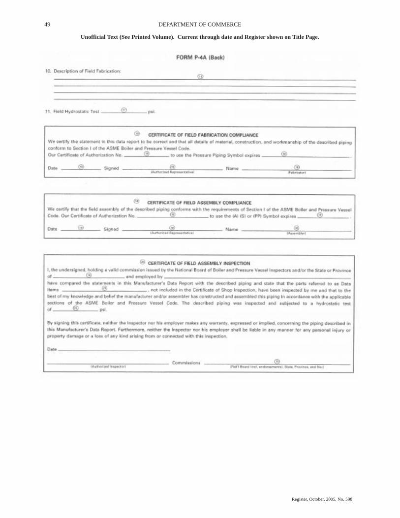
49 DEPARTMENT OF COMMERCE
Unofficial Text (See Printed Volume). Current through date and Register shown on Title Page.
Register, October, 2005, No. 598
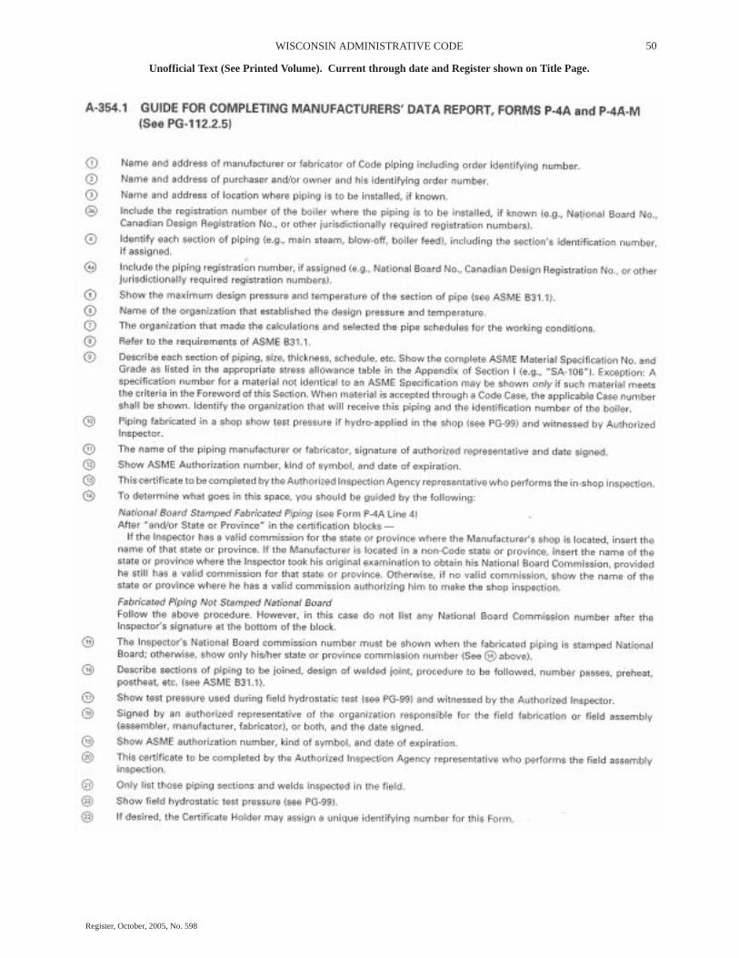
50WISCONSIN ADMINISTRATIVE CODE
Unofficial Text (See Printed Volume). Current through date and Register shown on Title Page.
Register, October, 2005, No. 598

51 DEPARTMENT OF COMMERCE
Unofficial Text (See Printed Volume). Current through date and Register shown on Title Page.
Register, October, 2005, No. 598

52WISCONSIN ADMINISTRATIVE CODE
Unofficial Text (See Printed Volume). Current through date and Register shown on Title Page.
Register, October, 2005, No. 598
53 DEPARTMENT OF COMMERCE
Unofficial Text (See Printed Volume). Current through date and Register shown on Title Page.
Register, October, 2005, No. 598
EXCERPTS FROM: ASME BOILER AND PRESSURE VESSEL CODESECTION IV − HEATING BOILERS
2004 EDITION
INTRODUCTION
The rules of this Section of the Code cover minimumconstruction requirements for the design, fabrication, installa-tion, and inspection of steam heating, hot water heating, hotwater supply boilers which are directly fired with oil, gas, elec-tricity, coal, or other solid or liquid fuels and for operation at orbelow the pressure and temperature limits set forth in this docu-ment. Similar rules for potable water heaters are also included.
For Section IV application, the boiler proper or other vesselsterminate at:
(a) the first circumferential joint welding end connections;
(b) the face of the first flange in bolted flanged end connec-tions; or
(c) the first threaded joint in that type of connection.
Pressure retaining covers for inspection opening, such asmanhole covers and handhold covers, and plugs are includedwithin the scope of this Section.
The rules are divided into four major Parts: HG, applying toall materials of construction except as provided for in Part HLW;Part HF, applying to assemblies fabricated of wrought material,except as provided for in Part HLW; Part HC, applying to castiron assemblies; and Part HLW, applying to potable water heat-ers. Part HF is further subdivided into Subpart HW, containingrules for welded construction, and Subpart HB, containing rulesfor brazed construction.
The parts and Subparts of this Section are divided into Arti-cles. Each article is given a number and a title, as for example,Part HG, Article 3, Design. Articles are divided into paragraphswhich are given a three−digit number, the first of which corre-sponds to the Article number. Thus, under Article 3 of Part HG,paragraph HG−307 will be found. Paragraphs are further subdi-vided into subparagraphs. Major subdivisions of paragraphs aredesignated by three− or four−digit numbers followed by a deci-mal point and a digit or digits. Where necessary, further subdivi-sions are represented by letters and then by numbers in paren-theses. Minor subdivisions of the paragraphs are alsorepresented by letters. A reference to one of these paragraphs inthe text of the Section includes all of the applicable rules in thatparagraph. Thus, reference to HG−307 includes all the rules inHG−307.1 through HG−307.4.
This Section does not contain rules to cover all possibledetails of design and construction. Where complete details arenot given, it is intended that the manufacturer, subject to theacceptance of the Authorized Inspector, shall provide details ofdesign and construction which will be as safe as otherwiserequired by these rules.
When the strength of any part cannot be computed with a sat-isfactory assurance of safety, these rules provide procedures forestablishing its maximum allowable working pressure.
ARTICLE 1SCOPE AND SERVICE RESTRICTIONS
HG−100 SCOPE
(a) The rules of Part HG apply to steam heating boilers, hotwater heating boilers, hot water supply boilers, and to appurte-nances thereto. They shall be used in conjunction with the spe-cific requirements in Part HF, Boilers of Wrought Materials, andPart HC, Cast Iron Boilers, whichever is applicable. The fore-word provides the basis for these rules. Part HG is not intendedto apply to potable water heaters except as provided for in PartHLW.
(b) This Part contains mandatory requirements, specific pro-hibitions, and nonmandatory guidance for materials, designs,fabrication, examinations, inspection, testing, certification, andpressure relief.
(c) Laws or regulations issued by a municipality, state, pro-vincial, federal, or other enforcement or regulatory body havingjurisdiction at the location of installation, establish the manda-tory applicability of these rules, in whole or in part.
HG−101 SERVICE RESTRICTIONS
HG−101.1 Service Restrictions. The rules of this Sectionare restricted to the following services:
(a) steam boilers for operation at pressures not exceeding 15psi (100 kPa);
(b) hot water heating boilers and hot water supply boilers foroperating at pressures not exceeding 160 psi (1 100 kPa) and/ortemperatures not exceeding 250�F (120�C), at or near the boileroutlet, except that when some of the wrought materials per-mitted by Part HF are used, a lower temperature is specified.
HG−101.2 Services in Excess of Those Covered by ThisSection. For services exceeding the limits specified inHG−101.1, the rules of Section I shall apply.
HG−102 UNITS
Either U.S. Customary units or SI units may be used for com-pliance with all requirements of this edition, but one system shallbe used consistently throughout for all phases of construction.
Either the U.S. Customary units or SI units that are listed inMandatory Appendix 6 are identified in the text, or are identifiedin the nomenclature for equations shall be used consistently forall phases for construction (e.g. materials, design, fabrication,and reports). Since values in the two systems are not exactequivalents, each system shall be used independently of theother without mixing U.S. Customary units and SI units.
When SI units are selected, U.S. Customary values in refer-enced specifications that do not contain SI units shall be con-verted to SI values to at least three significant figures for use incalculations and other aspects of construction.
ARTICLE 2MATERIAL REQUIREMENTS
HG−200 GENERAL MATERIAL REQUIREMENTS

54WISCONSIN ADMINISTRATIVE CODE
Unofficial Text (See Printed Volume). Current through date and Register shown on Title Page.
Register, October, 2005, No. 598
HG−200.1 Materials Subject to Pressure Stress. Materialsubject to stress due to pressure shall conform to one of the spec-ifications given in Section II and shall be limited to those that arepermitted in HF−200 for boilers of wrought materials andHC−200 for cast iron boilers.
HG−200.2 Internal Parts Subject to Deterioration. Mate-rials shall not be used for internal parts which are liable to faildue to deterioration when subjected to saturated steam tempera-tures at or below the maximum allowable working pressure.
HG−200.3 Materials Not Found in Section II. Material notcovered by specifications in Section II shall not be used unlessauthorization to use the material is granted by the Boiler andPressure Vessel Committee on the basis of data submitted to theCommittee in accordance with Appendix A.
HG−200.4 Materials Use Not Limited by SpecificationTitle. The title or scope paragraph of a material specification inSection II as respects product form or service shall not limit theuse of a material, provided the material is suitable for theapplication and its use is permitted by the rules of this Section.
HG−200.5 Materials Use Not Limited by Method of Pro-duction. Materials covered by specifications in Section II arenot restricted as to the method of production unless so stated inthe Specification, and as long as the product complies with therequirements of the Specification.
HG−200.6 Materials With Thickness Exceeding Specifi-cation Limits. Materials having thicknesses outside of the lim-its given in the title or scope clause of a specification in SectionII may be used in construction, provided they comply with otherrequirements of the Specification and with all thickness require-ments of this Code.
HG−200.7 Nonpressure Part Materials. Material for non-pressure parts, such as skirts, supports, baffles, lugs, clips, andextended heat−transfer surfaces, need not conform to the speci-fications for the material to which they are attached or to a mate-rial specification permitted in HF−200 or HC−200; but, ifwelded, they shall be of weldable quality. The allowable stressvalue shall not exceed 80% of the maximum allowable stresspermitted for similar material in Tables HF−300.1 andHF−300.2. Satisfactory performance of a specimen in such ser-vice shall not make the material acceptable for use in pressureparts of a vessel.
HG−201 SPECIFIC MATERIAL REQUIREMENTS
Specific material requirements for assemblies constructed ofwrought materials are given in Part HF, Article 2 and for assem-blies constructed of cast iron in Part HC, Article 2.
ARTICLE 4PRESSURE RELIEVING DEVICES
HG−400 PRESSURE RELIEVING VALVE REQUIRE-MENTS
HG−400.1 Safety Valve Requirements for Steam Boilers
(a) Each steam boiler shall have one or more officially ratedsafety valves that are identified with the V or HV Symbol of thespring pop type adjusted and sealed to discharge at a pressure notto exceed 15 psi (100 kPa).
(b) No safety valve for a steam boiler shall be smaller thanNPS � (DN 15). No safety valve shall be larger than NPS 4 �
(DN 115). The inlet opening shall have an inside diameter equalto, or greater than, the seat diameter.
(c) The minimum relieving capacity of valve or valves shallbe governed by the capacity marking on the boiler called for inHG−530.
(d) The minimum valve capacity in pounds per hour shall bethe greater of that determined by dividing the maximum Btu out-put at the boiler nozzle obtained by the firing of any fuel forwhich the unit is installed by 1,000, or shall be determined on thebasis of the pounds (kg) of steam generated per hour per squarefoot (m2) of boiler heating surface as given in Table HG−400.1.For cast iron boilers constructed to the requirements of Part HC,the minimum valve capacity shall be determined by the maxi-mum output method. In many cases a greater relieving capacityof valves will have to be provided than the minimum specifiedby these rules. In every case, the requirement of HG−400.1(e)shall be met.
(e) The safety valve capacity for each steam boiler shall besuch that with the fuel burning equipment installed, and oper-ated at maximum capacity, the pressure cannot rise more than 5psi (35 kPa) above the maximum allowable working pressure.
(f) When operating conditions are changed, or additionalboiler heating surface is installed, the valve capacity shall beincreased, if necessary, to meet the new conditions and be inaccordance with HG−400.1(e). The additional valves required,on account of changed conditions, may be installed on the outletpiping provided there is no intervening valve.
TABLE HG−400.1MINIMUM POUNDS OF STEAM PER HOURPER SQUARE FOOT OF HEATING SURFACE
FiretubeBoilers
WatertubeBoilers
Boiler heating surface:
Hand fired 5 (24) 6 (29)Stoker fired 7 (34) 8 (39)Oil, gas or pulverized
fuel fired 8 (39) 10 (49)Waterwall heating surface:
Hand fired 8 (39) 8 (39)Stoker fired 10 (49) 12 (59)Oil, gas or pulverized
fuel 14 (68) 16 (78)
GENERAL NOTES:(a) When a boiler is fired only by a gas having a heat value not in excess of
200 Btu/cu ft (7400 kJ/m3), the minimum safety valves or safety relief valvesrelieving capacity may be based on the values given for hand fired boilers above.
(b) The minimum safety valve or safety relief valve relieving capacity for elec-tric boilers shall be 3� lb/hr/kW (1.6 kg/hr/kW) input.
(c) For heating surface determination, see HG−403.(d) For extended heating surface, the minimum lb/hr/sq ft may be determined
by the Manufacturer [see HG 403(d)].
HG−400.2 Safety and Relief Valve Requirements for HotWater Boilers
(a) Each hot water heating or supply boiler shall have at leastone officially rated safety relief valve, of the automatic reseating

55 DEPARTMENT OF COMMERCE
Unofficial Text (See Printed Volume). Current through date and Register shown on Title Page.
Register, October, 2005, No. 598
type, identified with the V or HV Symbol, and set to relieve ator below the maximum allowable working pressure of the boiler.
(b) Hot water heating or supply boilers limited to a watertemperature not in excess of 210�F (99�C) may have in lieu ofthe valve(s) specified in (a) above, one or more officially ratedtemperature and pressure safety relief valves of the automaticreseating type identified with the HV symbol, and set to relieveat or below the maximum allowable working pressure of theboiler.
(c) When more than one safety relief valve is used on eitherhot water heating or hot water supply boilers, the additionalvalves shall be officially rated and may have a set pressurewithin a range not to exceed 6 psi (40 kPa) above the maximumallowable working pressure of the boiler up to and including 60psi (400 kPa), and 5% for those having a maximum allowableworking pressure exceeding 60 psi (400 kPa).
(d) No safety relief valve shall be smaller than NPS � (DN20) nor larger than NPS 4 � (DN 115) except that boilers havinga heat input not greater than 15,000 Btu/hr (4.4 kW) may beequipped with a rated safety relief valve of NPS � (DN 15).
(e) The required steam relieving capacity, in pounds per hour(kg/hr), of the pressure relieving device or devices on a boilershall be the greater of that determined by dividing the maximumoutput in BTU at the boiler nozzle obtained by the firing of anyfuel for which the unit is installed by 1000, or shall be deter-mined on the basis of pounds (kg) of steam generated per hourper square foot (m2) of boiler heating surface as given in TableHG−400.1. For cast iron boilers constructed to the requirementsof Part HC, the minimum valve capacity shall be determined bythe maximum output method. In many cases a greater relievingcapacity of valves will have to be provided than the minimumspecified by these rules. In every case, the requirements ofHG−400.2(g) shall be met.
(f) When operating conditions are changed, or additionalboiler heating surface is installed, the valve capacity shall beincreased, if necessary, to meet the new conditions and shall bein accordance with HG−400.2(g). The additional valvesrequired, on account of changed conditions, may be installed onthe outlet piping provided there is no intervening valve.
(g) Safety relief valve capacity for each boiler with a singlesafety relief valve shall be such that, with the fuel burning equip-ment installed and operated at maximum capacity, the pressurecannot rise more than 10% above the maximum allowable work-ing pressure. When more than one safety relief valve is used, theoverpressure shall be limited to 10% above the set pressure ofthe highest set valve allowed by HG−400.2(a).
HG−400.3 Safety and Safety Relief Valves for Tanks andHeat Exchangers
(a) Steam to Hot Water Supply. When a hot water supply isheated indirectly by steam in a coil or pipe within the service lim-itations set forth in HG−101, the pressure of the steam used shallnot exceed the safe working pressure of the hot water tank, anda safety relief valve at least NPS 1 (DN 25), set to relieve at orbelow the maximum allowable working pressure of the tank,shall be applied on the tank.
(b) High Temperature Water to Water Heat Exchanger.1
When high temperature water is circulated through the coils or
tubes of a heat exchanger to warm water for space heating or hotwater supply, within the service limitations set fort in HG−101,the heat exchanger shall be equipped with one or more officiallyrated safety relief valves that are identified with the V or HVSymbol, set to relieve at or below the maximum allowable work-ing pressure of the heat exchanger, and of sufficient rated capac-ity to prevent the heat exchanger pressure from rising more than10% above the maximum allowable working pressure of thevessel.
(c) High Temperature Water to Steam Heat Exchanger.1
When high temperature water is circulated through the coils ortubes of a heat exchanger to generate low pressure steam, withinthe service limitations set forth in HG−101, the heat exchangershall be equipped with one or more officially rated safety valvesthat are identified with the V or HV Symbol, set to relieve at apressure not to exceed 15 psi (100 kPa), and of sufficient ratedcapacity to prevent the heat exchanger pressure from rising morethan 5 psi (35 kPa) above the maximum allowable working pres-sure of the vessel. For heat exchangers requiring steam pres-sures greater than 15 psi (100 kPa), refer to Section I or SectionVIII, Division 1.
1 Suggested installation practices for the secondary side of heat exchangers.
HG−401 MINIMUM REQUIREMENTS FOR SAFETYAND SAFETY RELIEF VALVES
HG−401.1 Mechanical Requirements
(a) The inlet opening shall have an inside diameter approxi-mately equal to, or greater than, the seat diameter. In no caseshall the maximum opening through any part of the valve be lessthan � in. (6 mm) in diameter or its equivalent area.
(b) Safety relief valves officially rated as to capacity shallhave pop action when tested by steam.
(c) O−rings or other packing devices when used on the stemsof safety relief valves shall be so arranged as not to affect theiroperation or capacity.
(d) The design shall incorporate guiding arrangements nec-essary to insure consistent operation and tightness. Excessivelengths of guiding surfaces should be avoided. Bottom guideddesigns are not permitted on safety relief valves.
(e) Safety valves shall have a controlled blowdown of 2 psito 4 psi (15 kPa to 30 kPa) and this blowdown need not be adjust-able.
(f) Safety valves shall be spring loaded. The spring shall bedesigned so that the full lift spring compression shall be nogreater than 80% of the nominal solid deflection. The perma-nent set of the spring (defined as the difference between the freeheight and height measured 10 min after the spring has beencompressed solid three additional times after presetting at roomtemperature) shall not exceed 0.5% of the free height.
(g) There shall be a lifting device and a mechanical connec-tion between the lifting device and the disk capable of lifting thedisk from the seat a distance of at least 1/16 in. (1.5 mm) with nopressure on the boiler.
(h) A body drain below seat level shall be provided by theManufacturer for all safety valves and safety relief valves,except that the body drain may be omitted when the valve seat

56WISCONSIN ADMINISTRATIVE CODE
Unofficial Text (See Printed Volume). Current through date and Register shown on Title Page.
Register, October, 2005, No. 598
is above the bottom of the inside diameter of the discharge pip-ing. For valves exceeding NPS 2 � (DN 65) the drain hole orholes shall be tapped not less than NPS 3/8 (DN 10). For valvesNPS 2 � (DN 65) or smaller, the drain hole shall not be less than� in. (6 mm) in diameter. Body drain connections shall not beplugged during or after field installation. In safety relief valvesof the diaphragm type, the space above the diaphragm shall bevented to prevent a buildup of pressure above the diaphragm.Safety relief valves of the diaphragm type shall be so designedthat failure or deterioration of the diaphragm material will notimpair the ability of the valve to relieve at the rated capacity.
(i) In the design of the body of the valve consideration shallbe given to minimizing the effects of water deposits.
(j) Valves shall be provided with wrenching surfaces to allowfor normal installations without damaging operating parts.
(k) The set pressure tolerances, plus or minus, of safetyvalves shall not exceed 2 psi (15 kPa), and for safety relief valvesshall not exceed 3 psi (20 kPa) for pressures up to and including60 psig (400 kPa) and 5% pressures above 60 psig (400 kPa).
(l) Safety valves shall be arranged so that they cannot be resetto relieve at a higher pressure than the maximum allowableworking pressure of the boiler.
HG−401.2 Material Selection
(a) Cast iron seats and disks are not permitted.
(b) Adjacent sliding surfaces such as guides and disks shallboth be of corrosion resistant material.
(c) Springs of corrosion resistant material or having a corro-sion resistant coating are required.
(d) Material for seats and disks should be such as to providea reasonable degree of resistance to steam cutting.
(e) Material for valve bodies and bonnets or their corre-sponding metallic pressure containing parts shall be listed inSection II, except that in cases where a manufacturer desires tomake use of materials other than those listed in Section II, heshall establish and maintain specifications requiring equivalentcontrol of chemical and physical properties and quality.
(f) Synthetic disk inserts of O−ring or other types if used shallbe compatible with the maximum design temperature estab-lished for the valve.
(g) No materials liable to fail due to deterioration or vulcan-ization when subjected to saturated steam temperature corre-sponding to capacity test pressure shall be used.
HG−401.3 Manufacture and Inspection
(a) A Manufacturer shall demonstrate to the satisfaction ofan ASME designee that his manufacturing, production, and test-ing facilities and quality control procedures will insure closeagreement between the performance of random production sam-ples and the performance of those valves submitted for capacitycertification.
(b) Manufacturing, inspection, and test operations includingcapacity are subject to inspections at any time by an ASMEdesignee.
(c) A Manufacturer may be granted permission to apply theHV Code Symbol to production pressure relief valves capacitycertified in accordance with HG−402.3 provided the followingtests are successfully completed. This permission shall expireon the fifth anniversary of the date it is initially granted. The per-mission may be extended for 5 year periods if the following testsare successfully repeated within the 6 month period before expi-ration.
(1) Two sample production pressure relief valves of a sizeand capacity within the capability of an ASME accepted lab-oratory shall be selected by an ASME designee.
(2) Operational and capacity tests shall be conducted inthe presence of an ASME designee at an ASME accepted lab-oratory. The valve Manufacturer shall be notified of the timeof the test and may have representatives present to witness thetest.
(3) Should any valve fail to relieve at or above its certifiedcapacity or should it fail to meet performance requirementsof this Section, the test shall be repeated at the rate of tworeplacement valves, selected in accordance withHG−401.3(c)(1), for each valve that failed.
(4) Failure of any of the replacement valves to meet thecapacity or the performance requirements of this Sectionshall be cause for revocation within 60 days of the authoriza-tion to use the Code Symbol of that particular type of valve.During this period, the Manufacturer shall demonstrate thecause of such deficiency and the action taken to guard againstfuture occurrence, and the requirements of HG−401.3(c)above shall apply.
(d) Safety valves shall be sealed in a manner to prevent thevalve from being taken apart without breaking the seal. Safetyrelief valves shall be set and sealed so that they cannot be resetwithout breaking the seal.
HG−401.4 Manufacturer’s Testing
(a) Every safety valve shall be tested to demonstrate its pop-ping point, blowdown, and tightness. Every safety relief valveshall be tested to demonstrate its opening point and tightness.Safety valves shall be tested on steam or air and safety reliefvalves on water, steam, or air. When the blowdown is nonadjust-able, the blowdown test may be performed on a sampling basis.
(b) A Manufacturer shall have a well−established programfor the application, calibration, and maintenance of test gages.
(c) Testing time on safety valves shall be sufficient, depend-ing on size and design, to insure that test results are repeatableand representative of field performance.
(d) Test fixtures and test drums shall be of adequate size andcapacity to assure representative pop action and accuracy ofblowdown adjustment.
(e) A tightness test shall be conducted at maximum expectedoperating pressure, but not at a pressure exceeding the reseatingpressure of the valve.
HG−401.5 Design Requirements. At the time of the sub-mission of valves for capacity certification, or testing in accord-ance with this Section, the ASME Designee has the authority toreview the design for conformity with the requirements of this

57 DEPARTMENT OF COMMERCE
Unofficial Text (See Printed Volume). Current through date and Register shown on Title Page.
Register, October, 2005, No. 598
Section, and to reject or require modification of designs whichdo not conform, prior to capacity testing.
HG−402 DISCHARGE CAPACITIES OF SAFETY ANDSAFETY RELIEF VALVES
HG−402.1 Valve Markings. Each safety or safety−reliefvalve shall be plainly marked with the required data by theManufacturer in such a way that the markings will not be obliter-ated in service. The markings shall be stamped, etched,impressed, or cast on the valve or on a nameplate, which shallbe securely fastened to the valve.
(a) The markings shall include the following:
(1) the name or an acceptable abbreviation of theManufacturer;
(2) Manufacturer’s design or type number;
(3) NPS size _____ in. (DN) (the nominal pipe size of thevalve inlet);
(4) set pressure _____ psi;
(5) capacity _____ lb/hr (kg/hr), or capacity ______Btu/hr in accordance with HG−402.7(a);
(6) year built or, alternatively, a coding may be marked onthe valves such that the valve Manufacturer can identify theyear the valve was assembled and tested; and
(7) ASME Symbol as shown in Fig. HG−402.
(b) Nameplates of safety or safety−relief valves may bemarked solely in metric units under the following conditions:
(1) The pressure−relief device will be installed in a loca-tion where metric units are required or accepted by localauthorities, if any.
(2) Metric units shall be those required by the user whennot mandated by enforcement authorities.
(3) The Manufacturer’s quality control system shall pro-vide for the conversion from U.S. customary units to the met-ric units that will be marked on the nameplate.
HG−402.2 Authorization to Use ASME Stamp. Eachsafety valve to which the Code Symbol (Fig. HG−402) is to beapplied shall be produced by a Manufacturer and/or Assemblerwho is in possession of a valid Certificate of Authorization. (SeeHG−540.)
FIG. HG−402 OFFICIAL SYMBOL FOR STAMP TODENOTE THE AMERICAN SOCIETY OF MECHANICALENGINEERS’ STANDARD
HG−402.3 Determination of Capacity to Be Stamped onValves. The Manufacturer of the valves that are to be stampedwith the Code symbol shall submit valves for testing to a placewhere adequate equipment and personnel are available to con-duct pressure and relieving−capacity tests which shall be madein the presence of and certified by an authorized observer. The
place, personnel, and authorized observer shall be approved bythe Boiler and Pressure Vessel Committee. The valves shall betested in one of the following three methods.
(a) Coefficient Method. Tests shall be made to determine thelift, popping, and blowdown pressures, and the capacity of atleast three valves each of three representative sizes (a total ofnine valves). Each valve of a given size shall be set at a differentpressure. However, safety valves for steam boilers shall have allnine valves set at 15 psig (100 kPa). A coefficient shall be estab-lished for each test as follows:
KD = Actual steam flow = Coefficient of Theoretical steam flow discharge
The average of the coefficients KD of the nine tests required shallbe multiplied by 0.90, and this product shall be taken as the coef-ficient K of that design. The stamped capacity for all sizes andpressures shall not exceed the value determined from the follow-ing formulas:
For 45 deg seat,
(U.S. Customary Units)
W = 51.5 πDLP x 0.707K
(SI Units)
W = 5.25 πDLP x 0.707K
For flat seat,
(U.S. Customary Units)
W = 51.5 πDLPK
(SI Units)
W = 5.25 πDLP
For nozzle,
(U.S. Customary Units)
W = 51.5 APK
(SI Units)
W = 5.25 APK
where
W = weight of steam/hrD = seat diameterL = liftP = (1.10 x set pressure + 14.7) psia or (1.10 x set pressure +
0.101) MPa, for hot water applications or = (5.0 psi + 15 psi set + 14.7) psia or (0.035 MPa + 0.100MPa set + 0.101) MPa, for steam boilers
K = coefficient of discharge for the designA = nozzle−throat area
Note: The maximum and minimum coefficient determined by the tests of avalve design shall not vary more than ±5% from the average. If one or more testsare outside the acceptable limits, one valve of the Manufacturer’s choice shall bereplaced with another valve of the same size and pressure setting or by a modifica-tion of the original valve. Following this test a new average coefficient shall be cal-culated, excluding the replaced valve test. If one or more tests are now outside theacceptable limits, as determined by the new average coefficient, a valve of theManufacturer’s choice must be replaced by two valves of the same size and pres-sure as the rejected valve. A new average coefficient, including the replacementvalves, shall be calculated. If any valve, excluding the two replaced valves, nowfalls outside the acceptable limits, the tests shall be considered unsatisfactory.
58WISCONSIN ADMINISTRATIVE CODE
Unofficial Text (See Printed Volume). Current through date and Register shown on Title Page.
Register, October, 2005, No. 598
(b) Slope Method. If a Manufacturer wishes to apply theCode Symbol to a design of pressure relief valves, four valvesof each combination of pipe and orifice size shall be tested.These four valves shall be set at pressures that cover the approxi-mate range of pressures for which the valve will be used, or thatcover the range available at the certified test facility that shallconduct the tests. The capacities shall be based on these fourtests as follows.
(1) The slope (W/P) of the actual measured capacity ver-sus the flow pressure for each test point shall be calculatedand averaged:
slope = W/P = measured capacity absolute flow pressure, psia
All values derived from the testing must fall within ±5% ofthe average value:
minimum slope = 0.95 x average slope
maximum slope = 1.05 x average slope
If the values derived from the testing do not fall between theminimum and maximum slope values, the AuthorizedObserver shall require that additional valves be tested at therate of two for each valve beyond the maximum and mini-mum values with a limit of four additional valves.
(2) The relieving capacity to be stamped on the valve shallnot exceed 90% of the average slope times the absolute accu-mulation pressure:
rated slope = 0.90 x average slope
stamped capacity ≤ rated slope x (1.10 x set pressure + 14.7)psia or (1.10 x set pressure + 101) kPa for hot water applica-tions
(c) Three−Valve Method. If a Manufacturer wishes to applythe Code Symbol to steam safety valves or safety relief valvesof one or more sizes of a design set at one pressure, he shall sub-mit three valves of each size of each design set at one pressurefor testing and the stamped capacity of each size shall not exceed90% of the average capacity of the three valves tested.
Note: The discharge capacity as determined by the test of each valve tested shallnot vary by more than ±5% of the average capacity of the three valves tested. Ifone of the three valve tests falls outside of the limits, it may be replaced by twovalves and a new average calculated based on all four valves, excluding thereplaced valve.
ARTICLE 6INSTRUMENTS, FITTINGS, AND CONTROLS
HG−600 GENERAL
All instruments, fittings, and controls described in this Arti-cle shall be installed prior to operation.
HG−601 FOR STEAM HEATING BOILERS
HG−602 STEAM GAGES
(a) Each steam boiler shall have a steam gage or a compoundsteam gage connected to its steam space or to its water columnor to its steam connection. The gage or piping to the gage shallcontain a siphon or equivalent device that will develop andmaintain a water seal that will prevent steam from entering the
gage tube. The piping shall be so arranged that the gage cannotbe shut off from the boiler except by a cock placed in the pipeat the gage and provided with a tee− or lever−handle arranged tobe parallel to the pipe in which it is located when the cock isopen. The gage connection boiler tapping, external siphon, orpiping to the boiler shall not be less than NPS � (DN 8). Wheresteel or wrought iron pipe or tubing is used, the boiler connectionand external siphon shall be not less than NPS � (DN 15). Fer-rous and nonferrous tubing having inside diameters at leastequal to that of standard pipe sizes listed above may be substi-tuted for pipe.
(b) The scale on the dial of a steam boiler gage shall be gradu-ated to not less than 30 psi (200 kPa) nor more than 60 psi (414kPa). The travel of the pointer from 0 psi to 30 psi (0 kPa to 200kPa) pressure shall be at least 3 in. (75 mm).
HG−603 WATER GAGE GLASSES
(a) Each steam boiler shall have one or more water gageglasses attached to the water column or boiler by means ofvalved fittings not less than NPS � (DN 15), with the lower fit-ting provided with a drain valve of a type having an unrestricteddrain opening not less than � in. (6 mm) in diameter to facilitatecleaning. Gage glass replacement shall be possible with theboiler under pressure. Water glass fittings may be attacheddirectly to a boiler.
Boilers having an internal vertical height of less than 10 in.(250 mm) may be equipped with a water level indicator of theGlass Bull’s−Eye type provided the indicator is of sufficient sizeto show the water at both normal operating and low−water cutofflevels.
(b) The lowest visible part of the water gage glass shall be atleast 1 in. (25 mm) above the lowest permissible water level rec-ommended by the boiler Manufacturer. With the boiler operat-ing at this lowest permissible water level, there shall be no dan-ger of overheating any part of the boiler.
Each boiler shall be provided at the time of the manufacturewith a permanent marker indicating the lowest permissiblewater level. The marker shall be stamped, etched, or cast inmetal; or it shall be a metallic plate attached by rivets, screws,or welding; or it shall consist of material with documented testsshowing its suitability as a permanent marking for the applica-tion. This marker shall be visible at all times. Where the boileris shipped with a jacket, this marker may be located on thejacket.
Note: Transparent material other than glass may be used for the water gage pro-vided that the material will remain transparent and has proved suitable for the pres-sure, temperature, and corrosive conditions expected in service.
(c) In electric boilers of the submerged electrode type, thewater gage glass shall be so located to indicate the water levelsboth at startup and under maximum steam load conditions asestablished by the manufacturer.
(d) In electric boilers of the resistance element type, the low-est visible part of the water gage shall be located at least 1 in. (25mm) above the lowest permissible water level specified by theManufacturer. Each electric boiler of this type shall also beequipped with an automatic low−water cutoff on each boilerpressure vessel so located as to automatically cut off the power
59 DEPARTMENT OF COMMERCE
Unofficial Text (See Printed Volume). Current through date and Register shown on Title Page.
Register, October, 2005, No. 598
supply to the heating elements before the surface of the waterfalls below the visible part of the glass.
(e) Tubular water glasses on electric boilers having a normalwater content not exceeding 100 gal (300 l) shall be equippedwith a protective shield.
(f) A water level indicator using an indirect sensing methodmay be used in lieu of an operating water gauge glass; however,a water gauge glass must be installed and operable but may beshut off by valving. The water level indicator must be attachedto a water column or directly to the boiler by means of valvedfittings not less than NPS � (DN 15). The device shall be pro-vided with a drain valve of a type having an unrestricted drainopening not less than � in. (6 mm) in diameter to facilitate clean-ing. Service and replacement of internal parts and/or housingshall be possible with the boiler under pressure.
HG−604 WATER COLUMN AND WATER LEVEL CON-TROL PIPES
(a) The minimum size of ferrous or nonferrous pipes con-necting a water column to a steam boiler shall be NPS 1 (DN 25).No outlet connections, except for damper regulator, feedwaterregulator, steam gages, or apparatus which does not permit theescape of any steam or water except for manually operatedblowdowns, shall be attached to a water column or the pipingconnecting a water column to a boiler (see HG 705 for introduc-tion of feedwater into a boiler). If the water column, gage glass,low−water fuel cutoff, or other water level control device is con-nected to the boiler by pipe and fittings, no shutoff valves of anytype shall be placed in such pipe, and a cross or equivalent fittingto which a drain valve and piping may be attached shall beplaced in the water piping connection at every right angle turnto facilitate cleaning. The water column drain pipe and valveshall be not less than NPS � (DN 20).
(b) The steam connections to the water column of a horizon-tal firetube wrought boiler shall be taken from the top of the shellor the upper part of the head, and the water connection shall betaken from a point not above the center line of the shell. For acast iron boiler, the steam connection to the water column shallbe taken from the top of an end section or the top of the steamheader, and the water connection shall be made on an end sectionnot less than 6 in. (150 mm) below the bottom connection to thewater gage glass.
HG−605 PRESSURE CONTROL
Each automatically fired steam boiler shall be protected fromoverpressure by two pressure−operated controls.
(a) Each individual automatically fired steam boiler shallhave a safety limit control that will cut off the fuel supply to pre-vent steam pressure from exceeding the 15 psi (100 kPa) maxi-mum allowable working pressure of the boiler. Each controlshall be constructed to prevent a pressure setting above 15 psi(100 kPa).
(b) Each individual steam boiler shall have a control that willcut off the fuel supply when the pressure reaches an operatinglimit, which shall be less than the maximum allowable pressure.
(c) Shutoff valves of any type shall not be placed in the steampressure connection between the boiler and the controlsdescribed in (a) and (b) above. These controls shall be protected
with a siphon or equivalent means of maintaining a water sealthat will prevent steam from entering the control. The controlconnection boiler tapping, external siphon, or piping to theboiler shall not be less than NPS � (DN 8), but where steel orwrought iron pipe or tubing is used, they shall not be less thanNPS � (DN 15). The minimum size of an external siphon shallbe NPS � (DN 8) or 3/8 in. (10 mm) O.D. nonferrous tubing.
HG−606 AUTOMATIC LOW−WATER FUEL CUTOFFAND/OR WATER FEEDING DEVICE
(a) Each automatically fired steam or vapor−system boilershall have an automatic low−water fuel cutoff so located as toautomatically cut off the fuel supply when the surface of thewater falls to the lowest visible part of the water gage glass. Ifa water feeding device is installed, it shall be so constructed thatthe water inlet valve cannot feed water into the boiler through thefloat chamber and so located as to supply requisite feedwater.
(b) Such a fuel cutoff or water feeding device may beattached directly to a boiler. A fuel cutoff or water feedingdevice may also be installed in the tapped openings available forattaching a water glass direct to a boiler, provided the connec-tions are made to the boiler with nonferrous tees or Y’s not lessthan NPS � (DN 15) between the boiler and the water glass sothat the water glass is attached directly and as close as possibleto the boiler; the run of the tee or Y shall take the water glass fit-tings, and the side outlet or branch of the tee or Y shall take thefuel cutoff or water feeding device. The ends of all nipples shallbe reamed to full−size diameter.
(c) Fuel cutoffs and water feeding devices embodying a sepa-rate chamber shall have a vertical drain pipe and a blowoff valvenot less than NPS � (DN 20), located at the lowest point in thewater equalizing pipe connections so that the chamber and theequalizing pipe can be flushed and the device tested.
HG−607 MODULAR STEAM HEATING BOILERS
(a) Each module of a modular steam heating boiler shall beequipped with:
(1) steam gage, see HG−602;
(2) water gage glass, see HG−603;
(3) a pressure control that will cut off the fuel supply whenthe pressure reaches an operating limit, which shall be lessthan the maximum allowable pressure;
(4) low water cutoff, see HG−606.
(b) The assembled modular steam boiler shall also beequipped with a safety limit control that will cut off the fuel sup-ply to prevent steam pressure from exceeding the 15 psi (100kPa) maximum allowable working pressure of the boiler. Thecontrol shall be constructed to prevent a pressure setting above15 psi (100 kPa).
HG−610 FOR HOT WATER HEATING OR HOT WATERSUPPLY BOILERS
HG−611 PRESSURE OR ALTITUDE GAGES
(a) Each hot water heating or hot water supply boiler shallhave a pressure or altitude gage connected to it or to its flow con-nection in such a manner that it cannot be shut off from the boilerexcept by a cock with tee or lever handle, placed on the pipe near
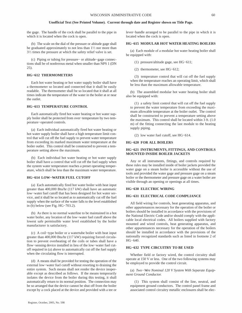
60WISCONSIN ADMINISTRATIVE CODE
Unofficial Text (See Printed Volume). Current through date and Register shown on Title Page.
Register, October, 2005, No. 598
the gage. The handle of the cock shall be parallel to the pipe inwhich it is located when the cock is open.
(b) The scale on the dial of the pressure or altitude gage shallbe graduated approximately to not less than 1� nor more than3� times the pressure at which the safety relief valve is set.
(c) Piping or tubing for pressure− or altitude−gage connec-tions shall be of nonferrous metal when smaller than NPS 1 (DN25).
HG−612 THERMOMETERS
Each hot water heating or hot water supply boiler shall havea thermometer so located and connected that it shall be easilyreadable. The thermometer shall be so located that it shall at alltimes indicate the temperature of the water in the boiler at or nearthe outlet.
HG−613 TEMPERATURE CONTROL
Each automatically fired hot water heating or hot water sup-ply boiler shall be protected from over−temperature by two tem-perature−operated controls.
(a) Each individual automatically fired hot water heating orhot water supply boiler shall have a high temperature limit con-trol that will cut off the fuel supply to prevent water temperaturefrom exceeding its marked maximum water temperature at theboiler outlet. This control shall be constructed to prevent a tem-perature setting above the maximum.
(b) Each individual hot water heating or hot water supplyboiler shall have a control that will cut off the fuel supply whenthe system water temperature reaches a preset operating temper-ature, which shall be less than the maximum water temperature.
HG−614 LOW−WATER FUEL CUTOFF
(a) Each automatically fired hot water boiler with heat inputgreater than 400,000 Btu/hr (117 kW) shall have an automaticlow−water fuel cutoff that has been designed for hot water ser-vice, and it shall be so located as to automatically cut off the fuelsupply when the surface of the water falls to the level establishedin (b) below (see Fig. HG−703.2).
(b) As there is no normal waterline to be maintained in a hotwater boiler, any location of the low−water fuel cutoff above thelowest safe permissible water level established by the boilermanufacturer is satisfactory.
(c) A coil−type boiler or a watertube boiler with heat inputgreater than 400,000 Btu/hr (117 kW) requiring forced circula-tion to prevent overheating of the coils or tubes shall have aflow−sensing device installed in lieu of the low−water fuel cut-off required in (a) above to automatically cut off the fuel supplywhen the circulating flow is interrupted.
(d) A means shall be provided for testing the operation of theexternal low−water fuel cutoff without resorting to draining theentire system. Such means shall not render the device inoper-able except as described as follows. If the means temporarilyisolates the device from the boiler during this testing, it shallautomatically return to its normal position. The connection maybe so arranged that the device cannot be shut off from the boilerexcept by a cock placed at the device and provided with a tee or
lever−handle arranged to be parallel to the pipe in which it islocated when the cock is open.
HG−615 MODULAR HOT WATER HEATING BOILERS
(a) Each module of a modular hot water heating boiler shallbe equipped with:
(1) pressure/altitude gage, see HG−611;
(2) thermometer, see HG−612;
(3) temperature control that will cut off the fuel supplywhen the temperature reaches an operating limit, which shallbe less than the maximum allowable temperature.
(b) The assembled modular hot water heating boiler shallalso be equipped with:
(1) a safety limit control that will cut off the fuel supplyto prevent the water temperature from exceeding the maxi-mum allowable temperature at the boiler outlet. The controlshall be constructed to prevent a temperature setting abovethe maximum. This control shall be located within 3 ft. (1.0m) of the fitting connecting the last module to the heatingsupply piping.
(2) low water fuel cutoff, see HG−614.
HG−620 FOR ALL BOILERS
HG−621 INSTRUMENTS, FITTINGS, AND CONTROLSMOUNTED INSIDE BOILER JACKETS
Any or all instruments, fittings, and controls required bythese rules may be installed inside of boiler jackets provided thewater gage on a steam boiler is accessible without the use oftools and provided the water gage and pressure gage on a steamboiler or the thermometer and pressure gage on a water boiler arevisible through an opening or openings at all times.
HG−630 ELECTRIC WIRING
HG−631 ELECTRICAL CODE COMPLIANCE
All field wiring for controls, heat generating apparatus, andother appurtenances necessary for the operation of the boiler orboilers should be installed in accordance with the provisions ofthe National Electric Code and/or should comply with the appli-cable local electrical codes. All boilers supplied with factorymounted and wired controls, heat generating apparatus, andother appurtenances necessary for the operation of the boilersshould be installed in accordance with the provisions of thenationally recognized standards such as listed in footnote 2 ofHG−640.
HG−632 TYPE CIRCUITRY TO BE USED
Whether field or factory wired, the control circuitry shalloperate at 150 V or less. One of the two following systems maybe employed to provide the control circuit.
(a) Two−Wire Nominal 120 V System With Separate Equip-ment Ground Conductor.
(1) This system shall consist of the line, neutral, andequipment ground conductors. The control panel frame andassociated control circuitry metallic enclosures shall be elec-

61 DEPARTMENT OF COMMERCE
Unofficial Text (See Printed Volume). Current through date and Register shown on Title Page.
Register, October, 2005, No. 598
trically continuous and be bonded to the equipment groundconductor.
(2) The equipment ground conductor and the neutral con-ductor shall be bonded together at their origin in the electricalsystem as required by the NEC.
(3) The line side of the control circuit shall be providedwith a time delay fuse sized as small as practicable.
(b) Two−Wire Nominal 120 V System Obtained By Using AnIsolation Transformer
(1) The two−wire control circuit shall be obtained fromthe secondary side of an isolation transformer. One wire fromthe secondary of this transformer shall be electrically contin-uous and shall be bonded to a convenient cold water pipe. Allmetallic enclosures of control components shall be securelybonded to this ground control circuit wire. The primary sideof the isolation transformer will normally be a two−wiresource with a potential of 230 V or 208 V or 440 V.
(2) Both sides of the two−wire primary circuit shall befused. The hot leg on the load side of the isolation trans-former shall be fused as small as practicable and in no casefused above the rating of the isolation transformer.
HG−633 LIMIT CONTROLS
Limit controls shall be wired on the hot or line side of the con-trol circuit.
HG−634 SHUTDOWN SWITCHES AND CIRCUITBREAKERS
A manually operated remote heating plant shutdown switchor circuit breaker should be located just outside the boiler roomdoor and marked for easy identification. Consideration shouldalso be given to the type and location of the switch to safeguardagainst tampering. If the boiler room door is on the buildingexterior the switch should be located just inside the door. If thereis more than one door to the boiler room, there should be a switchlocated at each door.
(a) For atmospheric−gas burners, and oil burners where a fanis on a common shaft with the oil pump, the complete burner andcontrols should be shut off.
(b) For power burners with detached auxiliaries, only the fuelinput supply to the firebox need be shut off.
HG−640 CONTROLS AND HEAT GENERATING APPA-RATUS
(a) Oil and gas−fired and electrically heated boilers shouldbe equipped with suitable primary (flame safe−guard) safetycontrols, safety limit switches, and burners or electric elementsas required by a nationally recognized standard.2
2 Examples of these nationally recognized standards are:
American National Standard/CSA Standard Z21.13/CSA 4.9 for Gas−
Fired Low Pressure Steam and Hot Water Boilers.
American National Standard/CSA Standard Z21.17/CSA 2.7 for Domes-
tic Gas Conversion Burners.
Underwriters Laboratories, Inc., UL 296, Standards for Safety, Oil Burn-
ers.
Underwriters Laboratories, Inc., UL 726, Standards for Safety, Oil Fired
Boiler Assemblies.
Underwriters Laboratories, Inc., UL 795, Standards for Safety, Commer-
cial−Industrial Gas−Heating Equipment.
Underwriters Laboratories, Inc., UL 834, Electric Heating, Water Supply
and Power Boilers.
(b) The symbol of the certifying organization3 which hasinvestigated such equipment as having complied with a nation-ally recognized standard shall be affixed to the equipment andshall be considered as evidence that the unit was manufacturedin accordance with that standard.
3 A certifying organization is one that provides uniform testing, examination,
and listing procedures under established, nationally recognized standards and
that is acceptable to the authorities having jurisdiction.
ARTICLE 7INSTALLATION REQUIREMENTS
HG−700 INSTALLATION REQUIREMENTS, ALLBOILERS
HG−701 MOUNTING SAFETY AND SAFETY RELIEFVALVES
HG−701.1 Permissible Mounting. Safety valves and safetyrelief valves shall be located in the top or side1 of the boiler.They shall be connected directly to a tapped or flanged openingin the boiler, to a fitting connected to the boiler by a short nipple,to a Y−base, or to a valveless header connecting steam or wateroutlets on the same boiler. Coil or header type boilers shall havethe safety valve or safety relief valve located on the steam or hotwater outlet end. Safety valves and safety relief valves shall beinstalled with their spindles vertical. The opening or connectionbetween the boiler and any safety valve or safety relief valveshall have at least the area of the valve inlet.
1 The top or side of the boiler shall mean the highest practicable part of the
boiler proper but in no case shall the safety valve be located below the nor-
mal operating level and in no case shall the safety relief valve be located
below the lowest permissible water level.
HG−701.2 Requirements for Common Connections forTwo or More Valves
(a) When a boiler is fitted with two or more safety valves onone connection, this connection shall have a cross−sectionalarea not less than the combined areas of inlet connections of allthe safety valves with which it connects.
(b) When a Y−base is used, the inlet area shall be not lessthan the combined outlet areas. When the size of the boilerrequires a safety valve or safety relief valve larger than 4 � in.

62WISCONSIN ADMINISTRATIVE CODE
Unofficial Text (See Printed Volume). Current through date and Register shown on Title Page.
Register, October, 2005, No. 598
(115 mm) in diameter, two or more valves having the requiredcombined capacity shall be used. When two or more valves areused on a boiler, they may be single, directly attached, ormounted on a Y−base.
HG−701.3 Threaded Connections. A threaded connectionmay be used for attaching a valve.
HG−701.4 Prohibited Mountings. Safety and safety reliefvalves shall not be connected to an internal pipe in the boiler.
HG−701.5 Use of Shutoff Valves Prohibited. No shutoffof any description shall be placed between the safety or safetyrelief valve and the boiler, or on discharge pipes between suchvalves and the atmosphere.
HG−701.6 Safety and Safety Relief Valve Discharge Pip-ing
(a) A discharge pipe shall be used. Its internal cross−sec-tional area shall be not less than the full area of the valve outletor of the total of the valve outlets discharging thereinto and shallbe as short and straight as possible and so arranged as to avoidundue stress on the valve or valves. A union may be installedin the discharge piping close to the valve outlet. When an elbowis placed on a safety or safety relief valve discharge pipe, it shallbe located close to the valve outlet downstream of the union.
(b) The discharge from safety or safety relief valves shall beso arranged that there will be no danger of scalding attendants.The safety or safety relief valve discharge shall be piped awayfrom the boiler to the point of discharge, and there shall be provi-sions made for properly draining the piping. The size andarrangement of discharge piping shall be independent of otherdischarge piping and shall be such that any pressure that may
exist or develop will not reduce the relieving capacity of therelieving devices below that required to protect the boiler.
HG−701.7 Temperature and Pressure Safety ReliefValves. Hot water heating or supply boilers limited to a watertemperature of 210�F (99�C) may have one or more officiallyrated temperature and pressure safety relief valves installed.The requirements of HG−701.1 through HG−701.6 shall be met,except as follows:
(a) A Y−type fitting shall not be used.
(b) If additional valves are used they shall be temperature andpressure safety relief valves.
(c) When the temperature and pressure safety relief valve ismounted directly on the boiler with no more than 4 in. (100 mm)maximum interconnecting piping, the valve may be installed inthe horizontal position with the outlet pointed down.
HG−703 PIPING2
2 Guidance for the design of piping systems may be found in ASME B31.9,
Building Services Piping.
HG−703.1 Provisions for Expansion and Contraction.Provisions shall be made for the expansion and contraction ofsteam and hot water mains connected to boilers by providingsubstantial anchorage at suitable points and by providing swingjoints when boilers are installed in batteries, so there will be noundue strain transmitted to the boilers. See Figs. HG−703.1(a),HG−703.1(b), and HG−703.2 for typical schematic arrange-ments of piping incorporating strain absorbing joints for steamand hot water heating boilers.

63 DEPARTMENT OF COMMERCE
Unofficial Text (See Printed Volume). Current through date and Register shown on Title Page.
Register, October, 2005, No. 598

64WISCONSIN ADMINISTRATIVE CODE
Unofficial Text (See Printed Volume). Current through date and Register shown on Title Page.
Register, October, 2005, No. 598
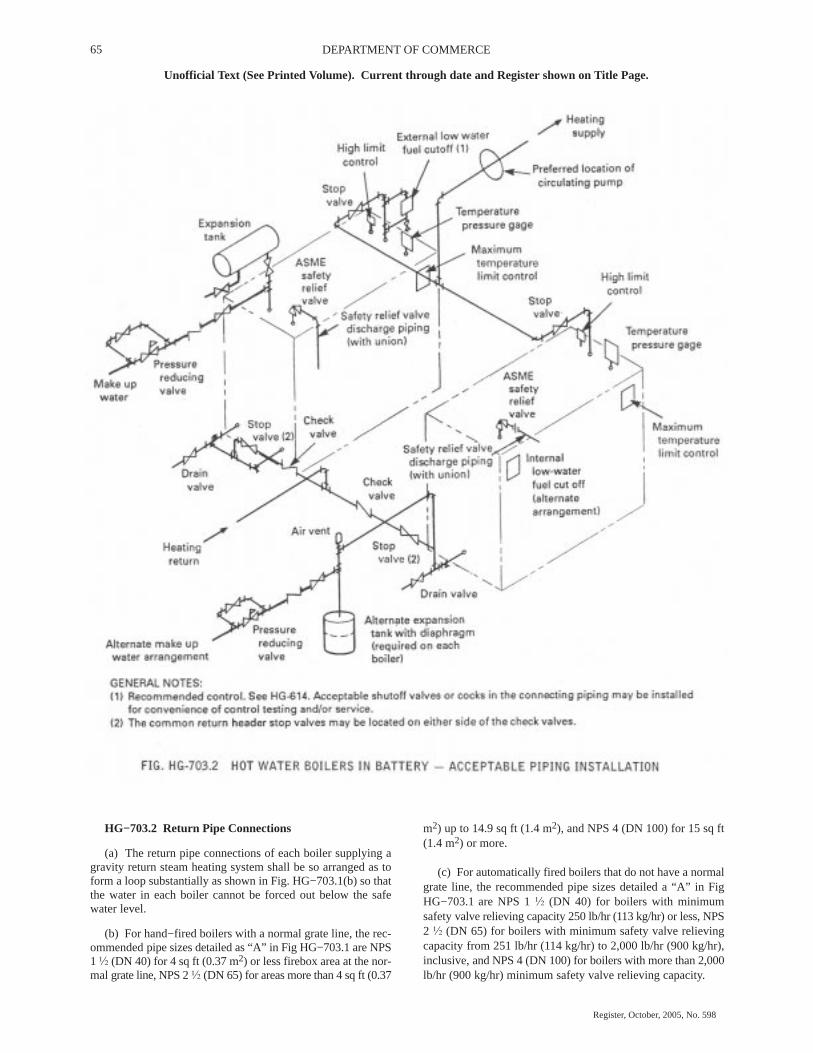
65 DEPARTMENT OF COMMERCE
Unofficial Text (See Printed Volume). Current through date and Register shown on Title Page.
Register, October, 2005, No. 598
HG−703.2 Return Pipe Connections
(a) The return pipe connections of each boiler supplying agravity return steam heating system shall be so arranged as toform a loop substantially as shown in Fig. HG−703.1(b) so thatthe water in each boiler cannot be forced out below the safewater level.
(b) For hand−fired boilers with a normal grate line, the rec-ommended pipe sizes detailed as “A” in Fig HG−703.1 are NPS1 � (DN 40) for 4 sq ft (0.37 m2) or less firebox area at the nor-mal grate line, NPS 2 � (DN 65) for areas more than 4 sq ft (0.37
m2) up to 14.9 sq ft (1.4 m2), and NPS 4 (DN 100) for 15 sq ft(1.4 m2) or more.
(c) For automatically fired boilers that do not have a normalgrate line, the recommended pipe sizes detailed a “A” in FigHG−703.1 are NPS 1 � (DN 40) for boilers with minimumsafety valve relieving capacity 250 lb/hr (113 kg/hr) or less, NPS2 � (DN 65) for boilers with minimum safety valve relievingcapacity from 251 lb/hr (114 kg/hr) to 2,000 lb/hr (900 kg/hr),inclusive, and NPS 4 (DN 100) for boilers with more than 2,000lb/hr (900 kg/hr) minimum safety valve relieving capacity.

66WISCONSIN ADMINISTRATIVE CODE
Unofficial Text (See Printed Volume). Current through date and Register shown on Title Page.
Register, October, 2005, No. 598
(d) Provision shall be made for cleaning the interior of thereturn piping at or close to the boiler. Washout openings may beused for return pipe connections and the washout plug placed ina tee or a cross so that the plug is directly opposite and as closeas possible to the opening in the boiler.
HG−705 FEEDWATER AND MAKEUP WATER CON-NECTIONS
(a) Steam Boilers. Feedwater or water treatment shall beintroduced into a boiler through the return piping system. Alter-natively, feedwater or water treatment may be introducedthrough an independent connection. The water flow from theindependent connection shall not discharge directly againstparts of the boiler exposed to direct radiant heat from the fire.Feedwater or water treatment shall not be introduced throughopenings or connections provided for inspection or cleaning,safety valve, water column, water gage glass, or pressure gage.The feedwater pipe shall be provided with a check valve near theboiler and a stop valve or cock between the check valve and theboiler or between the check valve and the return pipe system.
(b) Hot Water Boilers. Makeup water may be introduced intoa boiler through the piping system or through an independentconnection. The water flow from the independent connectionshall not discharge directly against parts of the boiler exposed todirect radiant heat from the fire. Makeup water shall not beintroduced through openings or connections provided exclu-sively for inspection or cleaning, safety relief valve, pressuregage, or temperature gage. The makeup water pipe shall be pro-vided with a check valve near the boiler and a stop valve or cockbetween the check valve and the boiler or between the checkvalve and the piping system.
HG−707 OIL HEATERS
(a) A heater for oil or other liquid harmful to boiler operationshall not be installed directly in the steam or water space withina boiler.
(b) Where an external type heater for such service is used,means shall be provided to prevent the introduction into theboiler of oil or other liquid harmful to boiler operation.
HG−708 STORAGE TANKS FOR HOT WATER SUPPLYSYSTEMS
If a system is to utilize a storage tank that exceeds the capacityexception of HLW−101.2(c), the tank shall be constructed inaccordance with the rules of Part HLW; Section VIII, Division1;or Section X. For tanks constructed to Section X, the maximumallowable temperature marked on the tank shall equal or exceedthe maximum water temperature marked on the boiler.
HG−709 PROVISIONS FOR THERMAL EXPANSION INHOT WATER SYSTEMS
All hot water heating systems incorporating hot water tanksor fluid relief columns shall be so installed as to prevent freezingunder normal operating conditions.
HG−709.1 Heating Systems With Open Expansion Tank.An indoor overflow from the upper portion of the expansiontank shall be provided in addition to an open vent, the indooroverflow to be carried within the building to a suitable plumbingfixture or the basement.
HG−709.2 Closed Heating Systems. An expansion tankshall be installed that will be consistent with the volume andcapacity of the system. If the system is designed for a workingpressure of 30 psi (200 kPa) or less, the tank shall be suitablydesigned for a minimum hydrostatic test pressure of 75 psi (520kPa). Expansion tanks for systems designed to operate above 30psi (200 kPa) shall be constructed in accordance with SectionVIII, Division 1. Alternatively, a tank built to Section X require-ments may be used if the pressure and temperature ratings of thetank are equal to or greater than the pressure and temperature rat-ings of the system. Provisions shall be made for draining thetank without emptying the system, except for prepressurizedtanks.
TABLE HG−709.2EXPANSION TANK CAPACITIES FOR FORCED HOT
WATER SYSTEMS1
[Based on average operating water temperature 195�F, fillpressure 12 psig (83 kPa), and maximum operating pressure 30psig (200 kPa)]
Tank Capacities, gal (m3)
System Volume,gal (m3)
PrepressurizedDiaphragm Type
NonpressurizedType
100 (0.38) 9 (0.034) 15 (0.057)
200 (0.76) 17 (0.064) 30 (0.114)
300 (1.14) 25 (0.095) 45 (0.170)
400 (1.51) 33 (0.125) 60 (0.227)
500 (1.89) 42 (0.159) 75 (0.284)
1000 (3.79) 83 (0.314) 150 (0.568)
2000 (7.57) 165 (0.625) 300 (1.136)Note: 1 System volume includes volume of water in boiler, radiation, and pip-
ing, not including the expansion tank. Expansion tank capacities are based on anacceptance factor of 0.4027 for pre−pressurized types and 0.222 for nonprepressur-ized types. A procedure for estimating system volume and determining expansiontank sizes for other design conditions may be found in Chapter 12 of the 1996HVAC Systems and Equipment Volume of the ASHRAE Handbook.
The minimum capacity of the closed type expansion tankmay be determined from Table HG−709.2 or from the followingformula where the necessary information is available:
(U.S. Customary Units)
Vt = [0.00041T − 0.0466)Vs] / [(Pa/Pf) − (Pa/Po)]
(SI Units)
Vt = [(0.18155T − 8.236) Vs] / [(Pa/Pf) − (Pa/Po)]
where
Vt = minimum volume of tanks
Vs = volume of system, not including tanks
T = average operating temperature
Pa = atmospheric pressure
Pf = fill pressure
Po = maximum operating pressure
HG−709.3 Hot Water Supply Systems. If a system isequipped with a check valve or pressure reducing valve in thecold water inlet line, consideration should be given to the instal-

67 DEPARTMENT OF COMMERCE
Unofficial Text (See Printed Volume). Current through date and Register shown on Title Page.
Register, October, 2005, No. 598
lation of an airtight expansion tank or other suitable air cushion.Otherwise, due to the thermal expansion of the water, the safetyrelief valve may lift periodically. If an expansion tank is pro-vided, it shall be constructed in accordance with Section VIII,Division 1 or Section X. Except for prepressurized tanks, whichshould be installed on the cold water side, provisions shall bemade for draining the tank without emptying the system. SeeFig. HLW−809.1 for a typical acceptable installation.
HG−710 STOP VALVES
HG−710.1 For Single Steam Boilers. When a stop valve isused in the supply pipe connection of a single steam boiler, thereshall be one used in the return pipe connection.
HG−710.2 For Single Hot Water Heating Boilers
(a) Stop valves shall be located at an accessible point in thesupply and return pipe connection as near the boiler nozzle as isconvenient and practicable, of a single hot water heating boilerinstallation to permit draining the boiler without emptying thesystem.
(b) When the boiler is located above the system and can bedrained without draining the system, stop valves may be elimi-nated.
HG−710.3 For Multiple Boiler Installations. A stop valveshall be used in each supply and return pipe connection of twoor more boilers connected to a common system. See Figs.HG−703.1 and HG−703.2.
HG−710.4 Type of Stop Valve(s)
(a) All valves or cocks shall conform with the applicable por-tions of HF−203 and may be ferrous or nonferrous.
(b) The minimum pressure rating of all valves or cocks shallbe at least equal to the pressure stamped upon the boiler, and thetemperature rating of such valves or cocks, including all internalcomponents, shall be not less than 250�F (120�C).
(c) Valves or cocks shall be flanged, threaded or have endssuitable for welding or brazing.
(d) All valves or cocks with stems or spindles shall haveadjustable pressure type packing glands and, in addition, all plugtype cocks shall be equipped with a guard or gland. The plug orother operating mechanism shall be distinctly marked in linewith the passage to indicate whether it is opened or closed.
(e) All valves or cocks shall have tight closure when underboiler hydrostatic test pressure.
HG−710.5 Identification of Stop Valves by Tags. Whenstop valves are used, they shall be properly designated substan-tially as follows by tags of metal or other durable material fas-tened to them:
Supply Valve − Number ( )
Do Not Close Without Also Closing Return Valve− Number ( )
Return Valve − Number ( )
Do Not Close Without Also Closing SupplyValve−Number ( )
HG−715 BOTTOM BLOWOFF AND DRAIN VALVES
(a) Bottom Blowoff Valve. Each steam boiler shall have a bot-tom blowoff connection fitted with a valve or cock connected tothe lowest water space practicable with a minimum size asshown in Table HG−715. The discharge piping shall be full sizeto the point of discharge.
TABLE HG−715SIZE OF BOTTOM BLOWOFF PIPING,
VALVES, AND COCKS
Minimum RequiredSafety Valve Capacity,
lb (kg) of steam/hr [Note 1]Blowoff Piping,Valves, andCocks Size, min. in. (mm)
Up to 500 (225)501 to 1250 (225 to 550)
1251 to 2500 (550 to 1200)2501 to 6000 (1200 to 2700)
6001 (2700) and larger
� (20)1 (25)
1� (32)1� (40)2 (50)
Note: 1 To determine the discharge capacity of safety relief valves in terms ofBtu, the relieving capacity in lb of steam/hr is multiplied by 1000.
(b) Boilers having a capacity of 25 gal (95 l) or less areexempt from the above requirements, except that they must havea � in. NPS (DN 20) minimum drain valve.
(c) Drain Valve. Each steam or hot water boiler shall haveone or more drain connections, fitted with valves or cocks con-necting to the lowest water containing spaces. The minimumsize of the drain piping, valves, and cocks shall be � in. (19 mm).The discharge piping shall be full size to the point of discharge.When the blowoff connection is located at the lowest water con-taining space, a separate drain connection is not required.
(d) Minimum Pressure Rating. The minimum pressure ratingof valves and cocks used for blowoff or drain purposes shall beat least equal to the pressure stamped on the boiler but in no caseless than 30 psi (200 kPa). The temperature rating of such valvesand cocks shall not be less than 250�F (120�C).
HG−716 MODULAR BOILERS
(a) Individual Modules
(1) The individual modules shall comply with all therequirements of Part HG, except as specified in HG−607,HG−615, and this paragraph. The individual modules shallbe limited to a maximum input of 400,000 Btuh (gas), 3 gal/hr(11 l/hr) (oil), or 115 kW (electricity).
(2) Each module of a steam heating boiler shall beequipped with:
(a) safety valve, see HG−701
(b) blowoff valve, see HG−715(a)
(c) drain valve, see HG−715(c)
(3) Each module of a modular hot water heating boilershall be quipped with:
(a) safety relief valve, see HG−701
(b) drain valve, see HG−715(c)
(b) Assembled Modular Boilers

68WISCONSIN ADMINISTRATIVE CODE
Unofficial Text (See Printed Volume). Current through date and Register shown on Title Page.
Register, October, 2005, No. 598
(1) The individual modules shall be manifolded togetherat the job−site without intervening valves. The header ormanifold piping is field piping and is exempt from Article 2,Part HG, HF, HB, or HC.
(2) The assembled modular steam heating boiler shall alsobe equipped with:
(a) feedwater connection, see HG−705(a)
(b) return pipe connection, see HG−703.2
(3) The assembled modular hot water heating boiler shallalso be equipped with:
(a) makeup water connection, see HG−705(b)
(b) provision for thermal expansion, see HG−709
(c) stop valves, see HG−710.2
HG−720 SETTING
Boilers of wrought materials of the wet−bottom type havingan external width of over 36 in. (900 mm) shall have not less than12 in. (300 mm) between the bottom of the boiler and the floor-line, with access for inspection. When the width is 36 in. (900mm) or less, the distance between the bottom of the boiler andthe floorline shall be not less than 6 in. (150 mm), except that,when any part of the wet bottom is not farther from an outer edgethan 12 in. (300 mm), this distance shall be not less than 4 in.(100 mm).
HG−725 METHODS OF SUPPORT
HG−725.1 Loadings
(a) The design and attachment of lugs, hangers, saddles, andother supports shall take into account the stresses due to hydro-static head in determining the minimum thickness required.Additional stresses imposed by effects other than working pres-sure of static head which increase the average stress by morethan 10% of the allowable working stress shall also be taken intoaccount. These effects include the weight of the component andits contents, and the method of support.
(b) In applying the requirements of (a) above, localizedstresses due to concentrated support loads, temperature changes,and restraint against dilation of the boiler due to pressure shallbe provided for. Lugs, hangers, brackets, saddles, and pads shallconform satisfactorily to the shape of the shell or surface towhich they are attached or are in contact.
HG−725.2 Boilers Over 72 in. (1 800 mm) Diameter. Ahorizontal−return tubular boiler over 72 in. (1 800 mm) in diam-eter shall be supported from steel hangers by the outside−sus-
pension type of setting, independent of the furnace wall. Thehangers shall be so designed that the load is properly distributed.
HG−725.3 Boilers Over 54 in. (1 400 mm) up to 72 in. (1800 mm) in Diameter. A horizontal−return tubular boiler over54 in. (1 400 mm) and up to and including 72 in. (1 800 mm) indiameter shall be supported by the outside−suspension type ofsetting, or at four points by not less than eight steel brackets setin pairs, the brackets of each pair to be spaced not over 2 in. (50mm) apart and the load to be equalized between them. [See Fig.HG−725(a).]
HG−725.4 Boilers up to 54 in. (1 400 mm) in Diameter.A horizontal−return tubular boiler up to and including 54 in. (1400 mm) in diameter shall be supported by the outside−suspen-sion type of setting, or by not less than two steel brackets on eachside.
HG−725.5 Supporting Members. If the boiler is supportedby structural steel work, the steel supporting members shall beso located or insulated that the heat from the furnace can notimpair their strength.
HG−725.6 Lugs or Hangers. Lugs, hangers, or bracketsmade of materials in accordance with the Code requirementsmay be attached by fusion welding provided they are attachedby fillet welds along the entire periphery or contact edges. Fig-ure HG−725(b) illustrates an acceptable design of hangerbracket with the additional requirement that the center pin belocated at the vertical center line over the center of the weldedcontact surface. The bracket plates shall be spaced at least 2 �
in. (64 mm) apart, but this dimension shall be increased if neces-sary to permit access for the welding operation. The stressescomputed by dividing the total load on each lug, hanger, orbracket, by the minimum cross−sectional area of the weld shallnot exceed 2800 psi (19 MPa). Where it is impractical to attachlugs, hangers, or brackets by welding studs with not less than 10threads/in. (approx. 4 threads/cm) may be used. In computingthe shearing stresses, the root area at the bottom of the threadshall be used. The shearing and crushing stresses on studs shallnot exceed 8% of the strength given in Table HF−300.1 for bolt-ing materials.
HG−725.7 Settings. Boilers of wrought materials of wet−bottom type having an external width of over 36 in. (900 mm)shall be supported so as to have a minimum clearance of 12 in.(300 mm), between the bottom of the boiler and the floor, tofacilitate inspection. When the width is 36 in. (900 mm) or less,the clearance between the bottom of the boiler and the floorlineshall be not less than 6 in. (150 mm), except when any part of thewet bottom is not farther from the outer edge than 12 in. (300mm). This clearance shall be not less than 4 in. (100 mm). Boilerinsulation, saddles, or other supports shall be arranged so thatinspection openings are readily accessible.

69 DEPARTMENT OF COMMERCE
Unofficial Text (See Printed Volume). Current through date and Register shown on Title Page.
Register, October, 2005, No. 598
EXCERPTS FROM: ASME BOILER AND PRESSURE VESSEL CODE
SECTION VIII − DIV 1 − CONSTRUCTION OF PRESSURE VESSELS2004 EDITION
INTRODUCTION
SCOPE
U−1 SCOPE
U−1(a)
U−1(a)(1) The Forward provides the basis for the rulesdescribed in this Division.
U−1(a)(2) For the scope of this Division, pressure vessels arecontainers for the containment of pressure, either internal orexternal. This pressure may be obtained from an externalsource, or by the application of heat from a direct or indirectsource, or any combination thereof.
U−1(a)(3) This Division contains mandatory requirements,specific prohibitions, and nonmandatory guidance for pressurevessel materials, design, fabrication, examination, inspection,testing, certification, and pressure relief. The Code does notaddress all aspects of these activities, and those aspects whichare not specifically addressed should not be considered prohib-ited. Engineering judgment must be consistent with the philoso-phy of this Division, and such judgments must never be used tooverrule mandatory requirements or specific prohibitions of thisDivision. See also informative and nonmandatory guidanceregarding metallurgical phenomena in Appendix A of SectionII, Part D.
U−1(b) This Division is divided into three Subsections, Man-datory Appendices, and Nonmandatory Appendices. Subsec-tion A consists of Part UG, covering the general requirementsapplicable to all pressure vessels. Subsection B covers specificrequirements that are applicable to the various methods used inthe fabrication of pressure vessels. It consists of Parts UW, UF,and UB dealing with welded, forged, and brazed methods,respectively. Subsection C covers specific requirements appli-cable to the several classes of materials used in pressure vesselconstruction. It consists of Parts UCS, UNF, UHA, UCI, UCL,UCD, UHT, ULW, and ULT dealing with carbon and low alloysteels, nonferrous metals, high alloy steels, cast iron, clad andlined material, cast ductile iron, ferritic steels with propertiesenhanced by heat treatment, layered construction, and low tem-perature materials, respectively. Section II, Part D also containstables of maximum allowable stress values for these classes ofmaterials.
The Mandatory Appendices address specific subjects notcovered elsewhere in this Division, and their requirements aremandatory when the subject covered is included in constructionunder this Division. The Nonmandatory Appendices provideinformation and suggested good practices.
U−1(c)
U−1(c)(1) The scope of this Division has been established toidentify the components and parameters considered in formulat-ing the rules given in this Division. Laws or regulations issuedby municipality, state, provincial, federal, or other enforcement
or regulatory bodies having jurisdiction at the location of aninstallation establish the mandatory applicability of the Coderules, in whole or in part, within their jurisdiction. Those lawsor regulations may require the use of this Division of the Codefor vessels or components not considered to be within its Scope.These laws or regulations should be reviewed to determine sizeor service limitations of the coverage which may be different ormore restrictive than those given here.
U−1(c)(2) Based on the Committee’s consideration, the fol-lowing classes of vessels are not included in the scope of thisDivision; however, any pressure vessel which meets all theapplicable requirements of this Division may be stamped withthe Code U Symbol:
(a) those within the scope of other Sections;
(b) fired process tubular heaters;
(c) pressure containers which are integral parts or compo-nents of rotating or reciprocating mechanical devices, such aspumps, compressors, turbines, generators, engines, and hydrau-lic or pneumatic cylinders where the primary design consider-ations and/or stresses are derived from the functional require-ments of the device;
(d) except as covered in U−1(f), structures whose primaryfunction is the transport of fluids from one location to anotherwithin a system of which it is an integral part, that is, piping sys-tems;
(e) piping components, such as pipe, flanges, bolting, gas-kets, valves, expansion joints, fittings, and the pressure contain-ing parts of other components, such as strainers and deviceswhich serve such purposes as mixing, separating, snubbing, dis-tributing, and metering or controlling flow, provided that pres-sure containing parts of such components are generally recog-nized as piping components or accessories;
(f) a vessel for containing water1 under pressure, includingthose containing air the compression of which serves only as acushion, when none of the following limitations are exceeded:
1 The water may contain additives provided the flash point of the aqueous
solution at atmospheric pressure is 185�F or higher. The flash point shall be
determined by the methods specified in ASTM D 93 or in ASTM D 56,
whichever is appropriate.
(1) a design pressure of 300 psi (2 MPa);
(2) a design temperature of 210�F (99�C);
(g) a hot water supply storage tank heated by steam or anyother indirect means when none of the following limitations isexceeded:
(1) a heat input of 200,000 Btu/hr (58.6 kW);
(2) a water temperature of 210�F (99�C);
(3) a nominal water containing capacity of 120 gal (450L);

70WISCONSIN ADMINISTRATIVE CODE
Unofficial Text (See Printed Volume). Current through date and Register shown on Title Page.
Register, October, 2005, No. 598
(h) vessels having an internal or external operating pressure(see 3−2) not exceeding 15 psi (100 kPa) with no limitation onsize [see UG−28(f)];
(i) vessels having an inside diameter, width, height, or crosssection diagonal not exceeding 6 in. (152 mm), with no limita-tion on length of vessel or pressure;
(j) pressure vessels for human occupancy.2
2 Requirements for pressure vessels for human occupancy are covered by
ANSI/ASME PVHO−1.
U−1(d) The rules of this Division have been formulated onthe basis of design principles and construction practices applica-ble to vessels designed for pressures not exceeding 3000 psi (20MPa). For pressures above 3000 psi (20 MPa), deviations fromand additions to these rules usually are necessary to meet therequirements of design principles and construction practices forthese higher pressures. Only in the event that after havingapplied these additional design principles and construction prac-tices the vessel still complies with all of the requirements of thisDivision may it be stamped with the applicable Code symbol.
U−1(e) In relation to the geometry of pressure containingparts, the scope of this Division shall include the following:
U−1(e)(1) where external piping; other pressure vesselsincluding heat exchangers; or mechanical devices, such aspumps, mixers, or compressors, are to be connected to the ves-sel:
(a) the welding end connection for the first circumferen-tial joint for welded connections [see UW−13(g)];
(b) the first threaded joint for screwed connections;
(c) the face of the first flange for bolted, flanged connec-tions;
(d) the first sealing surface for proprietary connections orfittings;
U−1(e)(2) where nonpressure parts are welded directly toeither the internal or external pressure retaining surface or apressure vessel, this scope shall include the design, fabrication,testing, and material requirements established for nonpressurepart attachments by the applicable paragraphs of this Division;3
3 These requirements for design, fabrication, testing, and material for non-
pressure part attachments do not establish the length, size, or shape of the
attachment material. Pads and standoffs are permitted and the scope can
terminate at the next welded or mechanical joint.
U−1(e)(3) pressure retaining covers for vessel openings,such as manhole and handhole covers;
U−1(e)(4) the first sealing surface for proprietary fittings orcomponents for which rules are not provided by this Division,such as gages, instruments, and nonmetallic components.
U−1(f) The scope of the Division includes provisions forpressure relief devices necessary to satisfy the requirements ofUG−125 through UG−136 and Appendix 11.
U−1(g) Unfired steam boilers as defined in Section I shall beconstructed in accordance with the rules of Section I or this Divi-sion [see UG−125(b) and UW−2(c)].
The following pressure vessels in which steam is generatedshall be constructed in accordance with the rules of this Divi-sion:
U−1(g)(1) vessels known as evaporators or heat exchang-ers;
U−1(g)(2) vessels in which steam is generated by the use ofheat resulting from operation of a processing system containinga number of pressure vessels such as used in the manufacture ofchemical and petroleum products;
U−1(g)(3) vessels in which steam is generated but not with-drawn for external use.
U−1(h) Pressure vessels or parts subject to direct firing fromthe combustion of fuel (solid, liquid, or gaseous), which are notwithin the scope of Sections I, III, or IV may be constructed inaccordance with the rules of this Division [see UW−2(d)].
U−1(i) Gas fired jacketed steam kettles with jacket operatingpressures not exceeding 50 psi (345 kPa) may be constructed inaccordance with the rules of this Division (see Appendix 19).
U−1(j) Pressure vessels exclusive of those covered inU−1(c), U−1(g), U−1(h), and U−1(i) that are not required by therules of this Division to be fully radiographed, which are not pro-vided with quick actuating closures (see UG−35), and that do notexceed the following volume and pressure limits may beexempted from inspection by Inspectors, as defined in UG−91,provided that they comply in all other respects with the require-ments of this Division:
U−1(j)(1) 5 cu ft (0.14 m3) in volume and 250 psi (1.7 MPa)design pressure; or
U−1(j)(2) 3 cu ft (0.08 m3) in volume and 350 psi (2.4 MPa)design pressure;
U−1(j)(3) 1 � cu ft (0.04 m3) in volume and 600 psi (4.1MPa) design pressure.
In an assembly of vessels, the limitations in (1) through (3)above apply to each vessel and not the assembly as a whole.Straight line interpolation for intermediate volumes and designpressures is permitted. Vessels fabricated in accordance withthis rule shall be marked with the “UM” Symbol in Fig. UG−116sketch (b) and with the data require in UG−116. Certificates ofCompliance shall satisfy the requirements of UG−120(a).
U−1(k) The degree of nondestructive examination(s) and theacceptance standards beyond the requirements of this Divisionshall be a matter of prior agreement between the Manufacturerand user or his designated agent.
GENERAL
U−2 GENERAL
(a) The user or his designated agent4 shall establish thedesign requirements for pressure vessels, taking into consider-ation factors associated with normal operation, such other con-

71 DEPARTMENT OF COMMERCE
Unofficial Text (See Printed Volume). Current through date and Register shown on Title Page.
Register, October, 2005, No. 598
ditions as startup and shutdown, and abnormal conditions whichmay become a governing design consideration (see UG−22).
4 For this Division, the user’s designated agent may be either a design agency
specifically engaged by the user, the Manufacturer of a system for a specific
service which includes a pressure vessel as a part and which is purchased by
the user, or an organization which offers pressure vessels for sale or lease for
specific services.
Such consideration shall include but shall not be limited tothe following:
(1) the need for corrosion allowances;
(2) the definition of lethal services. For example, seeUW−2(a).
(3) the need for postweld heat treatment beyond therequirements of this Division and dependent on service con-ditions;
(4) for pressure vessels in which steam is generated, orwater is heated [see U−1(g) and (h)], the need for piping,valves, instruments, and fittings to perform the functionscovered by PG−59 through PG−61 of Section I.
(b) Responsibilities5
5 See UG−90(b) and UG−90(c)(1) for summaries of the responsibilities of the
Manufacturer and the duties of the Inspector.
(1) The Manufacturer of any vessel or part to be marked withthe Code Symbol has the responsibility of complying with all ofthe applicable requirements of this Division and, through propercertification, of assuring that all work done by others also com-plies. The vessel or part Manufacturer shall have available forthe Inspector’s review the applicable design calculations. See10−5 and 10−15(d).
(2) Some types of work, such as forming, nondestructiveexamination, and heat treating, may be performed by others (forwelding, see UW−26 and UW−31). It is the vessel or partManufacturer’s responsibility to ensure that all work so per-formed complies with all the applicable requirements of thisDivision. After ensuring Code compliance, the vessel or partmay be Code stamped by the appropriate Code stamp holderafter acceptance by the Inspector.
(c) A vessel may be designed and constructed using any com-bination of the methods of fabrication and the classes of materialcovered by this Division provided the rules applying to eachmethod and material are complied with and the vessel is markedas required by UG−116.
(d) When the strength of any part cannot be computed witha satisfactory assurance of safety, the rules provide proceduresfor establishing its maximum allowable working pressure.
(e) It is the duty of the Inspector to make all of the inspectionsspecified by the rules of this Division, and of monitoring thequality control and the examinations made by the Manufacturer.He shall make such other inspections as in his judgment are nec-essary to permit him to certify that the vessel has been designedand constructed in accordance with the requirements. TheInspector has the duty of verifying that the applicable calcula-tions have been made and are on file at Manufacturer’s plant at
the time the Data Report is signed. Any questions concerning thecalculations raised by the Inspector must be resolved. SeeUG−90(c)(1).
(f) The rules of this Division shall serve as the basis for theinspector to:
(1) perform the required duties;
(2) authorize the applications of the Code Symbol;
(3) sign the Certificate of Shop (or Field Assembly)Inspection.
(g) This Division of Section VIII does not contain rules tocover all details of design and construction. Where completedetails are not given, it is intended that the Manufacturer, subjectto the acceptance of the Inspector, shall provide details of designand construction which will be as safe as those provided by therules of this Division.
(h) Field assembly of vessels constructed to this Divisionmay be performed as follows:
(1) The Manufacturer of the vessel completes the vessel inthe field, completes the Form U−1 or U−1A Manufacturer’sData Report, and stamps the vessel.
(2) The Manufacturer of parts of a vessel to be completed inthe field by some other party stamps these parts in accordancewith Code rules and supplies the Form U−2 or U−2A Manufac-turer’s Partial Data Report to the other party. The other party,who must hold a valid U Certificate of Authorization, makes thefinal assembly, required NDE, final pressure test; completes theForm U−1 or U−1A Manufacturer’s Data Report; and stamps thevessel.
(3) The field portion of the work is completed by a holder ofa valid U Certificate of Authorization other than the vesselManufacturer. The stamp holder performing the field work isrequired to supply a Form U−2 or U−2A Manufacturer’s PartialData Report covering the portion of the work completed by hisorganization (including data on the pressure test if conducted bythe stamp holder performing the field work) to the Manufacturerresponsible for the Code vessel. The vessel Manufacturerapplies his U stamp in the presence of a representative from hisInspection Agency and completes the Form U−1 or U−1AManufacturer’s Data Report with his Inspector.
In all three alternatives, the party completing and signing theForm U−1 or U−1A Manufacturer’s Data Report assumes fullCode responsibility for the vessel. In all three cases, eachManufacturer’s Quality Control System shall describe the con-trols to assure compliance for each Code stamp holder.
(i) For some design analyses, both a chart or curve and a for-mula or tabular data are given. Use of the formula or tabular datamay result in answers which are slightly different from the val-ues obtained from the chart or curve. However, the difference,if any, is within practical accuracy and either method is accepta-ble.
U−3 STANDARDS REFERENCED BY THIS DIVISION
(a) Throughout this Division references are made to variousstandards, such as ANSI standards, which cover pressure−tem-perature rating, dimensional, or procedural standards for pres-

72WISCONSIN ADMINISTRATIVE CODE
Unofficial Text (See Printed Volume). Current through date and Register shown on Title Page.
Register, October, 2005, No. 598
sure vessel parts. These standards, with the year of the accepta-ble edition, are listed in Table U−3.
(b) Rules for the use of these standards are stated elsewherein this Division.
U−4 UNITS OF MEASUREMENT
Either U.S. Customary units or SI units may be used for com-pliance with all requirements of this edition, but one system shallbe used consistently throughout for all phases of construction.
Either the U.S. Customary Units or SI units that are listed inMandatory Appendix 33 are identified in the text, or are identi-
fied in the nomenclature for equations, shall be used consistentlyfor all phases of construction (e.g. materials, design, fabrication,and reports). Since values in the two systems are not exactequivalents, each system shall be used independently of theother without mixing U.S. Customary units and SI units.
When SI units are selected, U.S. Customary values in refer-enced specifications that do not contain SI units shall be con-verted to SI values to at least three significant figures for use incalculations and other aspects of construction.6
6 Guidance for conversion of units from U.S. Customary to SI is found in
Nonmandaroty Appendix GG.
TABLE U−3YEAR OF ACCEPTABLE EDITION OF REFERENCED STANDARDS IN THIS DIVISION
Title Number YearSeat Tightness of Pressure Relief Valves API Std. 527 1991Unified Inch Screw Threads (UN and UNR Thread Form) ASME B1.1 1989 (R2001)(2)Pipe Threads, General Purpose (Inch) ANSI/ASME B1.20.1 1983 (R1992)(2)Cast Iron Pipe Flanges and Flanged Fittings, Classes 25, 125, 250, and 800 ASME/ANSI B16.1 1989Pipe Flanges and Flanged Fittings ASME B16.5 1996(1)Factory−Made Wrought Buttwelding Fittings ASME B16.9 2001Forges Fittings, Socket−Welding and Threaded ASME B16.11 2001Cast Bronze Threaded Fittings Classes 125 and 250 ANSI/ASME B16.15 1985Metallic Gaskets for Pipe Flanges – Ring−Joint, Spiral Wound, and Jacketed ASME B16.20 1993Cast Copper Alloy Pipe Flanges and Flanged Fittings, Class ASME B16.24 1991 150, 300, 400, 600, 900, 1500, and 2500Ductile Iron Pipe Flanges and Flanged Fittings, Class 150 and 300 ASME/ANSI B16.42 1987Large Diameter Steel Flanges, NPS 26 Through NPS 60 ASME B16.47 1996Square and Hex Nuts (Inch Series) ASME/ANSI B18.2.2 1987 (R1994)(2)Welded and Seamless Wrought Steel Pipe ASME B36.10M 2000Pressure Relief Devices ASME PTC 25 2001Qualifications for Authorized Inspection ASME QAI−1 (3)ASNT Central Certification Program ACCP Rev 3,ASNT Standard for Qualification and Certification of Nondestructive CP−189 1995 Testing PersonnelRecommended Practice for Personnel Qualification and Certification SNT−TC−1A 1996, A98 in Nondestructive TestingStandard Test Methods for Flash Point by Tag Closed Tester ASTM D 56 1987Standard Test Methods for Flash Point by Pensky−Martens Closed Tester ASTM D 93 1990Methods of Tension Testing of Metallic Materials ASTM E 8 1990Methods of Verification and Classification of Extensometers ASTM E 83 1990Reference Photographs for Magnetic Particle Indications on ASTM E 125 1963 (R1985)(2) Ferrous CastingsHardness Conversion Tables for Metals ASTM E 140 1988Standard Reference Radiographs for Heavy−Walled (2 to 4 �−in. ASTM E 186 1998 (51 to 114−mm)) Steel CastingsMethod of Conducting Drop Weight Test to Determine Nil Ductility ASTM E 208 1987a Transition Temperature of Ferritic SteelStandard Reference Radiographs for Heavy−Walled (4 � to 12−in. ASTM E 280 1998 (114 to 305−mm)) Steel CastingsStandard Reference Radiographs for Steel Castings up to 2 in. ASTM E 446 1998 (51 mm) in ThicknessMarking and Labeling Systems ANSI/UL−969 1991Note: (1) See UG−11(a)(2)
(2) R – Reaffirmed(3) See UG−91
PRESSURE RELIEF DEVICES
UG−125 GENERAL
(a) All pressure vessels within the Scope of this Division,irrespective of size or pressure, shall be provided with pressurerelief devices in accordance with the requirements of UG−125through UG−137. It is the responsibility of the user to ensurethat the required pressure relief devices are properly installedprior to initial operation. These pressure relief devices need not
be supplied by the vessel Manufacturer. Unless otherwisedefined in this Division, the definitions relating to pressure reliefdevices in Section 2 of ASME PTC 25 shall apply.
(b) An unfired steam boiler, as defined in U−1(g), shall beequipped with pressure relief devices required by Section I inso-far as they are applicable to the service of the particular installa-tion.
(c) All pressure vessels other than unfired steam boilers shallbe protected by a pressure relief device that shall prevent thepressure from rising more than 10% or 3 psi (20 kPa), whicheveris greater, above the maximum allowable working pressure

73 DEPARTMENT OF COMMERCE
Unofficial Text (See Printed Volume). Current through date and Register shown on Title Page.
Register, October, 2005, No. 598
except as permitted in (1) and (2) below. (See UG−134 for pres-sure settings.)
(1) When multiple pressure relief devices are provided andset in accordance with UG−134(a), they shall prevent the pres-sure from rising more than 16% or 4 psi (30 kPa), whichever isgreater, above the maximum allowable working pressure.
(2) Where an additional hazard can be created by exposureof a pressure vessel to fire or other unexpected sources of exter-nal heat, supplemental pressure relief devices shall be installedto protect against excessive pressure. Such supplemental pres-sure relief devices shall be capable of preventing the pressurefrom rising more than 21% above the maximum allowableworking pressure. [For additional information, see AppendixM, M−14(a)]. The same pressure relief devices may be used tosatisfy the capacity requirements of (c) or (c)(1) above and thisparagraph provided the pressure setting requirements ofUG−134(a) are met.
(3) Pressure relief devices, intended primarily for protectionagainst exposure of a pressure vessel to fire or other unexpectedsources of external heat installed on vessels having no perma-nent supply connection and used for storage at ambient tempera-tures of nonrefrigerated liquefied compressed gasses,41 areexcluded from the requirements of (c)(1) and (c)(2) above, pro-vided:
41 For the purpose of these rules, gases are considered to be substances
having a vapor pressure greater than 40 psia (300 kPa absolute) at 100�F
(40�C).
(a) the pressure relief devices are capable of preventing thepressure from rising more than 20% above the maximum allow-able working pressure of the vessels;
(b) the set pressure marked on these devices shall not exceedthe maximum allowable working pressure of the vessels;
(c) the vessels have sufficient ullage to avoid a liquid fullcondition;
(d) the maximum allowable working pressure of the vesselson which these pressure relief devices are installed is greaterthan the vapor pressure of the stored liquefied compressed gasat the maximum anticipated temperature42 that the gas will reachunder atmospheric conditions; and
42 Normally this temperature should not be less than 115�F (45�C).
(e) pressure relief valves used to satisfy these provisions alsocomply with the requirements of UG−129(a)(5), UG−131(c)(2),and UG−134(d)(2).
(d) Pressure relief devices shall be constructed, located, andinstalled so that they are readily accessible for inspection,replacement, and repair and so that they cannot be readily ren-dered inoperative (see Appendix M), and should be selected onthe basis of their intended service.
(e) Pressure relief valves or nonreclosing pressure reliefdevices43 may be used to protect against overpressure. Nonre-closing pressure relief devices may be used either alone or, ifapplicable, in combination with pressure relief valves on ves-sels.
43 A pressure relief valve is a pressure relief device which is designed to
reclose and prevent the further flow of fluid after normal conditions have
been restored. A nonreclosing pressure relief device is a pressure relief
device designed to remain open after operation.
Note: Use of nonreclosing pressure relief devices of some types may be advisa-ble on vessels containing substances that may render a pressure relief valve inop-erative, where a loss of valuable material by leakage should be avoided, or wherecontamination of the atmosphere by leakage of noxious fluids must be avoided.The use of rupture disk devices may also be advisable when very rapid rates of pres-sure rise may be encountered.
(f) Vessels that are to operate completely filled with liquidshall be equipped with pressure relief devices designed for liq-uid service, unless otherwise protected against overpressure.
(g) The pressure relief devices required in (a) above need notbe installed directly on a pressure vessel when either of the fol-lowing conditions apply:
(1) the source of pressure is external to the vessel and is undersuch positive control that the pressure in the vessel cannotexceed the maximum allowable working pressure at the operat-ing temperature except as permitted in (c) above (see UG−98),or under the conditions set forth in Appendix M.
(2) there are no intervening stop valves between the vesseland the pressure relief device or devices except as permittedunder UG−135(d).
Note: Pressure reducing valves and similar mechanical or electrical controlinstruments, except for pilot operated pressure relief valves as permitted inUG−126(b), are not considered as sufficiently positive in action to prevent excesspressures from being developed.
(h) Pressure relief valves for steam service shall meet therequirements of UG−131(b).
UG−126 PRESSURE RELIEF VALVES44
44 A safety valve is a pressure relief valve actuated by inlet static pressure
and characterized by rapid opening or pop action. A relief valve is a pressure
relief valve actuated by inlet static pressure which opens in proportion to
increase in pressure over the opening pressure. A safety relief valve is a
pressure relief valve characterized by rapid opening or pop action, or by
opening in proportion to the increase in pressure over the opening pressure,
depending on application. A pilot operated pressure relief valve is a pressure
relief valve in which the major relieving device is combined with and is
controlled by a self−actuated auxiliary pressure relief valve.
(a) Safety, safety relief and relief valves shall be of the directspring loaded type.
(b) Pilot operated pressure relief valves may be used, pro-vided that the pilot is self−actuated and the main valve will openautomatically at not over the set pressure and will discharge itsfull capacity if some essential part of the pilot should fail.
(c) The spring in a pressure relief valve shall not be set forany pressure more than 5% above or below that which the valveis marked, unless the setting is within the spring design rangeestablished by the valve Manufacturer or is determined to beacceptable to the Manufacturer. The initial adjustment shall beperformed by the Manufacturer, his authorized representative,or an assembler, and a valve data tag shall be provided that iden-tifies the set pressure capacity and date. The valve shall besealed with a seal identifying the Manufacturer, his authorizedrepresentative, or the Assembler performing the adjustment.
(d) The set pressure tolerances, plus or minus, of pressurerelief valves shall not exceed 2 psi (15 kPa) for pressure up to and

74WISCONSIN ADMINISTRATIVE CODE
Unofficial Text (See Printed Volume). Current through date and Register shown on Title Page.
Register, October, 2005, No. 598
including 70 psi (500 kPa) and 3% for pressures above 70 psi(500 kPa).
UG−127 NONRECLOSING PRESSURE RELIEFDEVICES
(a) Rupture Disk Devices45
45 A rupture disk device is a nonreclosing pressure relief device actuated by
inlet static pressure and designed to function by the bursting of a pressure
containing disk. A rupture disk is the pressure containing and pressure
sensitive element of a rupture disk device. Rupture disks may be designed in
several configurations, such as plain flat, prebulged, or reverse buckling. A
rupture disk holder is the structure which encloses and clamps the rupture
disk in position.
(1) General. Every rupture disk shall have a marked burstpressure established by rules of UG−137(d)(3) within amanufacturing design range46 at a specified disk temperature47
and shall be marked with a lot48 number. The burst pressure tol-erance at the specified disk temperature shall not exceed ±2psi(±15 kPa) for marked burst pressure up to and including 40 psi(300 kPa) and ±5% for marked burst pressure above 40 psi (300kPa).
46 The manufacturing design range is a range of pressure within which the
marked burst pressure must fall to be acceptable for a particular requirement
as agreed upon between the rupture disk Manufacturer and the user or his
agent. The manufacturing design range must be evaluated in conjunction
with the specified burst pressure to ensure that the marked burst pressure of
the rupture disk will always be within applicable limits of UG−134. Users
are cautioned that certain types of rupture disks have manufacturing ranges
that can result in a marked burst pressure greater than the specified burst
pressure.47 The specified disk temperature supplied to the rupture disk Manufacturer
shall be the temperature of the disk when the disk is expected to burst.48 A lot of rupture disks is those disks manufactured of a material at the same
time, of the same size, thickness, type, heat, and manufacturing process
including heat treatment.
(2) Relieving Capacity. The rated flow capacity of a pressurerelief system which uses a rupture disk device as the sole reliefdevice shall be determined by a value calculated under therequirements of (a) using a coefficient of discharge or (b) usingflow resistance below.
(a) When the rupture disk device discharges directly to atmo-sphere and
(1) is installed within eight pipe diameters from the vesselnozzle entry; and
(2) with a length of discharge pipe not greater than five pipediameters from the rupture disk device; and
(3) the nominal diameters of the inlet and discharge pipingare equal to or greater than the stamped NPS designator of thedevice, the calculated relieving capacity of a pressure relief sys-tem shall not exceed a value based on the applicable theoreticalflow equation [see UG−131(e)(2) and Appendix 11] for the vari-ous media multiplied by a coefficient of discharge K equal to0.62. The area A in the theoretical flow equation shall be theminimum net flow area49 as specified by the rupture disk deviceManufacturer.
49 The minimum net flow area is the calculated net area after a complete
burst of the disk with appropriate allowance for any structural members
which may reduce the net flow area through the rupture disk device. The net
flow area for sizing purposes shall not exceed the nominal pipe size area of
the rupture disk device.
(b) The calculated capacity of any pressure relief system maybe determined by analyzing the total system resistance to flow.This analysis shall take into consideration the flow resistance ofthe rupture disk device, piping and piping components includingthe exit nozzle on the vessels, elbows, tees, reducers, and valves.The calculation shall be made using accepted engineering prac-tices for determining fluid flow through piping systems. Thiscalculated relieving capacity shall be multiplied by a factor of0.90 or less to allow for uncertainties inherent with this method.The certified flow resistance50 KR for the rupture disk device,expressed as the velocity head loss, shall be determined in accor-dance with UG−131(k) through (r).
50 The certified flow resistance KR is a dimensionless factor used to calculate
the velocity head loss that results from the presence of a rupture disk device
in a pressure relief system.
(3) Application of Rupture Disks
(a) A rupture disk device may be used as the sole pressurerelieving device on a vessel.
Note: When rupture disk devices are used, it is recommended that the designpressure of the vessel be sufficiently above the intended operating pressure to pro-vide sufficient margin between operating pressure and rupture disk bursting pres-sure to prevent premature failure of the rupture dick due to fatigue or creep. Application of rupture disk devices to liquid service should be carefully evalu-ated to assure that the design of the rupture disk device and the dynamic energy ofthe system on which it is installed will result in sufficient opening of the rupturedisk.
(b) A rupture disk device may be installed between a pressurerelief valve51 and the vessel provided:
51 Use of a rupture disk device in combination with a pressure relief valve
shall be carefully evaluated to ensure that the media being handled and the
valve operational characteristics will result in opening of the valve coincident
with the bursting of the rupture disk.
(1) the combination of the pressure relief valve and the rup-ture disk is ample in capacity to meet the requirements ofUG−133(a) and (b);
(2) the marked capacity of a pressure relief valve (nozzletype) when installed with a rupture disk device between the inletof the valve and the vessel shall be multiplied by a factor of 0.90of the rated relieving capacity of the valve alone, or alternatively,the capacity of such a combination shall be established in accor-dance with (3) below;
(3) the capacity of the combination of the rupture disk deviceand the pressure relief valve may be established in accordancewith the appropriate paragraphs of UG−132;
(4) the space between a rupture disk device and a pressurerelief valve shall be provided with a pressure gage, a try cock,free vent, or suitable telltale indicator. This arrangement permitsdetection of disk rupture or leakage52.

75 DEPARTMENT OF COMMERCE
Unofficial Text (See Printed Volume). Current through date and Register shown on Title Page.
Register, October, 2005, No. 598
52 Users are warned that a rupture disk will not burst at its design pressure if
back pressure builds up in the space between the disk and the pressure relief
valve which will occur should leakage develop in the rupture disk due to
corrosion or other cause.
(5) the opening49 provided through the rupture disk, afterburst, is sufficient to permit a flow equal to the capacity of thevalve [(2) and (3) above], and there is no chance of interferencewith proper functioning of the valve; but in no case shall this areabe less than the area of the inlet of the valve unless the capacityand functioning of the specific combination of rupture diskdevice and pressure relief valve have been established by test inaccordance with UG−132.
(c) A rupture disk device may be installed on the outlet side53
of a pressure relief valve which is opened by direct action of thepressure in the vessel provided:
53 This use of a rupture disk device in series with the pressure relief valve is
permitted to minimize the loss by leakage through the valve of valuable or of
noxious or otherwise hazardous materials, and where a rupture disk alone or
disk located on the inlet side of the valve is impracticable, or to prevent
corrosive gases from a common discharge line from reaching the valve inter-
nals.
(1) the pressure relief valve will not fail to open at its properpressure setting regardless of any back pressure that can accu-mulate between the pressure relief valve disk and the rupturedisk. The space between the pressure relief valve disk and therupture disk shall be vented or drained to prevent accumulationof pressure, or suitable means shall be provided to ensure that anaccumulation of pressure does not affect the proper operation ofthe pressure relief valve.54
54 Users are warned that many types of pressure relief valves will not open at
the set pressure if pressure builds up in the space between the pressure relief
valve disk and the rupture disk device. A specially designed pressure relief
valve such as a diaphragm valve, pilot operated valve, or a valve equipped
with a balancing bellows above the disk may be required.
(2) the pressure relief valve is ample in capacity to meet therequirements of UG−125(c);
(3) the marked burst pressure of the rupture disk at the speci-fied disk temperature plus any pressure in the outlet piping shallnot exceed the design pressure of the outlet portion of the pres-sure relief valve and any pipe or fitting between the valve and therupture disk device. However, in no case shall the marked burstpressure of the rupture disk at the specified disk temperatureplus any pressure in the outlet piping exceed the maximumallowable working pressure of the vessel or the set pressure ofthe pressure relief valve.
(4) the opening provided through the rupture disk deviceafter breakage is sufficient to permit a flow equal to the ratedcapacity of the attached pressure relief valve without exceedingthe allowable overpressure;
(5) any piping beyond the rupture disk cannot be obstructedby the rupture disk or fragment;
(6) the system is designed to consider the adverse effects ofany leakage through the pressure relief valve or through the out-let side rupture disk device, to ensure system performance andreliability.55
55 Some adverse effects resulting from leakage may include obstructing the
flow path, corrosion of pressure relief valve components, and undesirable
bursts of the outlet side rupture disk.
(7) the bonnet of a balancing bellows or diaphragm type pres-sure relief valve shall be vented to prevent accumulation of pres-sure in the bonnet.
(b) Breaking Pin Device56
56 A breaking pin device is a nonreclosing pressure relief device actuated by
inlet static pressure and designed to function by the breakage of a load−carry-
ing section of a pin which supports a pressure containing member. A break-
ing pin is the load−carrying element of a breaking pin device. A breaking
pin housing is the structure which encloses the breaking pin mechanism. The
material of the housing shall be listed in Section II and be permitted for use
in this Division.
(1) Breaking pin devices shall not be used as single devicesbut only in combination between the pressure relief valve andthe vessel.
(2) The space between a breaking pin device and a pressurerelief valve shall be provided with a pressure gage, a try cock,a free vent, or suitable telltale indicator. This arrangement per-mits detection of breaking pin device operation or leakage.
(3) Each breaking pin device shall have a rated pressure andtemperature at which the pin will break. The breaking pin shallbe identified to a lot number and shall be guaranteed by theManufacturer to break when the rated pressure, within the fol-lowing tolerances, is applied to the device:
Rated Pressure, psi (kPa) Tolerance, Plus or Minus,psi (kPa)Minimum Maximum
30 (200) 150 (1 000) 5 (35)150 (1 000) 275 (1 900) 10 (70)275 (1 900) 375 (2600) 15 (100)
(4) The rated pressure of the breaking pin plus the tolerancein psi shall not exceed 105% of the maximum allowable workingpressure of the vessel to which it is applied.
(5) The rated pressure at the specified temperature57 shall beverified by breaking two or more sample breaking pins fromeach lot of the same material and the same size as those to beused. The lot size shall not exceed 25. The test shall be madein a device of the same form and pressure dimensions as that inwhich the breaking pin is to be used.
57 The specified temperature supplied to the breaking pin manufacturer shall
be the temperature of the breaking pin when an emergency condition exists
and the pin is expected to break.
(c) Spring Loaded Nonreclosing Pressure Relief Device
(1) A spring loaded nonreclosing pressure relief device, pres-sure actuated by means which permit the spring loaded portionof the device to open at the specified set pressure and remainopen until manually reset, may be used provided the design ofthe spring loaded nonreclosing device is such that if the actuat-ing means fail, the device will achieve full opening at or belowits set pressure. Such a device may not be used in combinationwith any other pressure relief device. The tolerance on openingpoint shall not exceed ±5%.

76WISCONSIN ADMINISTRATIVE CODE
Unofficial Text (See Printed Volume). Current through date and Register shown on Title Page.
Register, October, 2005, No. 598
(2) The calculated capacity rating of a spring loaded non-reclosing pressure relief device shall not exceed a value basedon the applicable theoretical formula (see UG−131) for the vari-ous media, multiplied by: K = coefficient = 0.62.
The area A (square inches) in the theoretical formula shall bethe flow area through the minimum opening of the spring loadednonreclosing pressure relief device.
(3) In lieu of the method of capacity rating in (2) above, aManufacturer may have the capacity of a spring loaded non-reclosing pressure relief device design certified in general accor-dance with the procedures of UG−131, as applicable.
UG− 128 LIQUID PRESSURE RELIEF VALVES
Any liquid pressure relief valve used shall be at least NPS �
(DN 15).
UG−129 MARKING
(a) Safety, Safety Relief, Relief, Liquid Pressure Relief, andPilot Operated Pressure Relief Valves. Each safety, safety relief,relief, liquid pressure relief, and pilot operated pressure reliefvalve NPS � (DN 15) and larger shall be plainly marked by theManufacturer or Assembler with the required data in such a waythat the marking will not be obliterated in service. The markingmay be placed on the valve or on a plate or plates that satisfy therequirements of UG−119:
(1) the name, or an acceptable abbreviation, of the Manufac-turer and the Assembler;
(2) Manufacturer’s design or type number;
(3) NPS size __________ (the nominal pipe size of the valveinlet);
(4) set pressure __________ psi (kPa), and, if applicable perUG−136(d)(4), cold differential test pressure __________ psi(kPa);
(5) certified capacity (as applicable):
(a) lb/hr of saturated steam at an overpressure of 10% or 3 psi(20 kPa), whichever is greater for valves certified on steam com-plying with UG−131(b); or
(b) gal/min of water at 70�F (20�C) at an overpressure of10% or 3 psi (20 kPa), whichever is greater for valves certifiedon water; or
(c) SCFM [standard cubic feet per minute at 60�F and 14.7psia (20�C and 101 kPa)], or lb/min, of air at an overpressure of10% or 3 psi (20 kPa), whichever is greater. Valves that arecapacity certified in accordance with UG−131(c)(2) shall bemarked “at 20% overpressure.”
(d) In addition to one of the fluids specified above, theManufacturer may indicate the capacity in other fluids (seeAppendix 11).
(6) year built, or alternatively, a coding may be marked onthe valve such that the valve Manufacturer or Assembler canidentify the year the valve was assembled or tested;
(7) ASME Symbol as shown in Fig. UG−129.1. The pilot ofa pilot operated pressure relief valve shall be plainly marked by
the Manufacturer or Assembler showing the name of theManufacturer, the Manufacturer’s design or type number, the setpressure in pounds per square inch, and the year built, or alterna-tively, a coding that the Manufacturer can use to identify the yearbuilt.
FIG. UG−129.1 OFFICIAL SYMBOL FOR STAMP TODENOTE THE AMERICAN SOCIETY OF MECHANICALENGINEERS’ STANDARD FOR PRESSURE RELIEFVALVES
On valves smaller than NPS � (DN 15), the markings may bemade on a metal tag attached by wire or adhesive meeting therequirements of UG−119 or other means suitable for the serviceconditions.
(b) Safety and safety relief valves certified for a steam dis-charging capacity under the provisions of Section I and bearingthe official Code Symbol Stamp of Section I for safety valvesmay be used on pressure vessels. The rated capacity in terms ofother fluids shall be determined by the method of conversiongiven in Appendix 11. [See UG−131(h).]
(c) Pressure Relief Valves in Combination With Rupture DiskDevices. Pressure relief valves in combination with rupture diskdevices shall be marked with the capacity as established inaccordance with UG−127(a)(3)(b)(2) (using 0.90 factor) or thecombination capacity factor established by test in accordancewith UG−132(a) or (b), in addition to the marking of UG−129(a)and (f) below. The marking may be placed on the pressure reliefvalve or rupture disk device or on a plate or plates that satisfy therequirements of UG−119. The marking shall include the follow-ing:
(1) name of Manufacturer of valve;
(2) design or type number of valve;
(3) name of Manufacturer of rupture disk device;
(4) design or type number of rupture disk device;
(5) capacity or combination capacity factor;
(6) name of organization responsible for this marking. Thisshall be either the vessel user, vessel Manufacturer, rupture diskManufacturer, or pressure relief valve Manufacturer.
(d) Pressure Relief Valves in Combination With Breaking PinDevices. Pressure relief valves in combination with breakingpin devices shall be marked in accordance with (a) above. Inaddition, the rated pressure shall be marked on the breaking pinand the breaking pin housing.
(e) Rupture Disk Devices. Every rupture disk shall be plainlymarked by the Manufacturer in such a way that the marking willnot be obliterated in service. The rupture disk marking may beplaced on the flange of the disk or on a metal tab that satisfies therequirements of UG−119. The marking shall include the follow-ing:

77 DEPARTMENT OF COMMERCE
Unofficial Text (See Printed Volume). Current through date and Register shown on Title Page.
Register, October, 2005, No. 598
(1) the name or identifying trademark of the Manufacturer;
(2) Manufacturer’s design or type number;
(3) lot number;
(4) disk material;
(5) size _________ [NPS (DN) of rupture disk holder];
(6) marked burst pressure __________ psi (kPa);
(7) specified disk temperature __________ �F (�C);
(8) minimum net flow area __________ sq in. (sq mm);
(9) certified flow resistance (as applicable):
(a) KRG __________ for rupture disk certified on air orgasses; or
(b) KRL __________ for rupture disk certified on liquid; or
(c) KRGL __________ for rupture disk certified on air orgases, and liquid;
(10) ASME symbol as shown in Fig. UG−129.2;
(11) year built, or alternatively, a coding may be marked onthe rupture disk such that the rupture disk device Manufacturercan identify the year the rupture disk device was assembled andtested.
Items (1), (2), and (5) above and flow direction shall also bemarked on the rupture disk holder.
(f) Spring Loaded Nonreclosing Pressure Relief Devices.Spring loaded nonreclosing pressure relief devices shall bemarked in accordance with (a) above except that the Code Sym-bol Stamp is to be applied only when the capacity has been estab-lished and certified in accordance with UG−127(c)(3) and allother requirements of UG−130 have been met.
FIG. UG−129.2 OFFICIAL SYMBOL FOR STAMP TODENOTE THE AMERICAN SOCIETY OF MECHANICALENGINEERS’ STANDARD FOR RUPTURE DISK DEVICES
UG−130 CODE SYMBOL STAMP
Each pressure vessel relief device58 to which the Code Sym-bol (see Figs. UG−129.1 and UG−129.2) will be applied shallhave been fabricated or assembled by a Manufacturer or Assem-bler holding a valid Certificate of Authorization (UG−117) andcapacity certified in accordance with the requirements of thisDivision. A Certified Individual (CI) shall provide oversight asrequired by UG−117(a). Each use of the Code Symbol shall alsobe documented on a Certificate of Conformance Form UV−1 orUD−1, as appropriate.
58 Vacuum relief devices are not covered by Code Symbol Stamp require-
ments.
UG−133 DETERMINATION OF PRESSURE RELIEV-ING REQUIREMENTS
(a) Except as permitted in (b) below, the aggregate capacityof the pressure relief devices connected to any vessel or systemof vessels for the release of a liquid, air, steam, or other vaporshall be sufficient to carry off the maximum quantity that can begenerated or supplied to the attached equipment without permit-ting a rise in pressure within the vessel of more than 16% abovethe maximum allowable working pressure when the pressurerelief devices are blowing.
(b) Pressure relief devices as permitted in UG−125(c)(2), asprotection against excessive pressure caused by exposure to fireor other sources of external heat, shall have a relieving capacitysufficient to prevent the pressure from rising more than 21%above the maximum allowable working pressure of the vesselwhen all pressure relief devices are blowing.
(c) Vessels connected together by a system of adequate pip-ing not containing valves which can isolate any vessel may beconsidered as one unit in figuring the required relieving capacityof pressure relief devices to be furnished.
(d) Heat exchangers and similar vessels shall be protectedwith a pressure relief device of sufficient capacity to avoid over-pressure in case of an internal failure.
(e) The official rated capacity, or the certified flow resistanceand minimum net flow area, of a pressure relief device shall bethat which is stamped on the device and guaranteed by theManufacturer.
(f) The rated pressure relieving capacity of a pressure reliefvalve for other than steam or air shall be determined by themethod of conversion given in Appendix 11.
(g) To prorate the relieving capacity at any relieving pressuregreater than 1.10p, as permitted under UG−125, a multipliermay be applied to the official relieving capacity of a pressurerelief device as follows:
(U.S. Customary Units)
P + 14.71.10p + 14.7
(SI Units)
P + 1011.10p + 101
where
P = relieving pressure, psig (kPa gage)
p = set pressure, psig (kPa gage)
For steam pressures above 1,500 psig (10.3 MPa gage), theabove multiplier is not applicable. For steam valves with reliev-ing pressures greater than 1,500 psig (10 MPa gage) and lessthan or equal to 3,200 psig (22.1 MPa gage), the capacity atrelieving pressures greater than 1.10p shall be determined usingthe equation for steam and the correction factor for high pressuresteam in UG−131(e)(2) with the permitted absolute relievingpressure and the coefficient K for that valve design.
UG−134 PRESSURE SETTING OF PRESSURE RELIEFDEVICES

78WISCONSIN ADMINISTRATIVE CODE
Unofficial Text (See Printed Volume). Current through date and Register shown on Title Page.
Register, October, 2005, No. 598
(a) When a single pressure relief device is used, the set pres-sure marked on the device shall not exceed the maximum allow-able working pressure of the vessel. When the required capacityis provided in more than one pressure relief device, only onepressure relief device need be set at or below the maximumallowable working pressure, and the additional pressure reliefdevices may be set to open at higher pressures but in no case ata pressure higher than 105% of the maximum allowable workingpressure, except as provided in (b) below.
(b) For pressure relief devices permitted in UG−125(c)(2) asprotection against excessive pressure caused by exposure to fireor other sources of external heat, the device marked set pressureshall not exceed 110% of the maximum allowable working pres-sure of the vessel. If such a pressure relief device is used to meetthe requirements of both UG−125(c) and UG−125(c)(2), thedevice marked set pressure shall not be over the maximumallowable working pressure.
(c) The pressure relief device set pressure shall include theeffects of static head and constant back pressure.
(d)(1) The set pressure tolerance for pressure relief valvesshall not exceed ±2 psi (15 kPa) for pressures up to and including70 psi (500 kPa) and ±3% for pressures above 70 psi (500 kPa),except as covered in (d)(2) below.
(2) The set pressure tolerance of pressure relief valves whichcomply with UG−125(c)(3) shall be within −0%, +10%.
(e) The burst pressure tolerance for rupture disk devices atthe specified disk temperature shall not exceed ±2 psi (15 kPa)of marked burst pressure up to 40 psi (300 kPa) and ±5% ofmarked burst pressure 40 psi (300 (kPa) and over.
UG−135 INSTALLATION
(a) Pressure relief devices intended for use in compressiblefluid service shall be connected to the vessel in the vapor spaceabove any contained liquid or to piping connected to the vaporspace in the vessel which is to be protected. Pressure reliefdevices intended for use in liquid service shall be connectedbelow the normal liquid level.
(b)(1) The opening through all pipe, fittings, and non−reclos-ing pressure relief devices (if installed) between a pressure ves-sel and its pressure relief valve shall have at least the area of thepressure relief valve inlet. The characteristics of this upstreamsystem shall be such that the pressure drop will not reduce the
relieving capacity below that required or adversely affect theproper operation of the pressure relief valve.
(2) The opening in the vessel wall shall be designed to pro-vide unobstructed flow between the vessel and its pressure reliefdevice (see Appendix M).61
61 Users are warned that the proper operation of various rupture disk devices
depends upon following the Manufacturer’s installation instructions closely
with regard to the flow direction marked on the device. Some device designs
will burst at pressures much greater than their marked burst pressure when
installed with the process pressure on the vent side of the device.
(c) When two or more required pressure relief devices areplaced on one connection, the inlet internal cross−sectional areaof this connection shall be either sized to avoid restricting flowto the pressure relief devices or made at least equal to the com-bined inlet areas of the safety devices connected to it. The flowcharacteristics of the upstream system shall satisfy the require-ments of (b) above. (See Appendix M.)
(d) There shall be no intervening stop valves between thevessel and its pressure relief device or devices, or between thepressure relief device or devices and the point of discharge,except:
(1) when these stop valves are so constructed or positivelycontrolled that the closing of the maximum number of blockvalves possible at one time will not reduce the pressure relievingcapacity provided by the unaffected pressure relief devicesbelow the required relieving capacity; or
(2) under conditions set forth in Appendix M.
(e) The pressure relief devices on all vessels shall be soinstalled that their proper functioning will not be hindered by thenature of the vessel’s contents.
(f) Discharge lines from pressure relief devices shall bedesigned to facilitate drainage or shall be fitted with drains toprevent liquid from lodging in the discharge side of the pressurerelief device, and such lines shall lead to a safe place of dis-charge. The size of the discharge lines shall be such that anypressure that may exist or develop will not reduce the relievingcapacity of the pressure relief devices below that required toproperly protect the vessel, or adversely affect the proper opera-tion of the pressure relief devices. [See UG−136−(a)(8) andAppendix M.]

79 DEPARTMENT OF COMMERCE
Unofficial Text (See Printed Volume). Current through date and Register shown on Title Page.
Register, October, 2005, No. 598
EXCERPTS FROM: POWER PIPING CODE ANSI/ASME B31.1
2004 EDITIONFOREWORD
The general philosophy underlying this Power Piping Code is to parallel those provisions of Section I, Power Boilers, of the ASMEBoiler and Pressure Vessel Code, as they can be applied to power piping systems. The Allowable Stress Values for power piping aregenerally consistent with those assigned for power boilers. This Code is more conservative than some other piping codes, reflectingthe need for long service life and maximum reliability in power plant installations.
The Power Piping Code as currently written does not differentiate between the design, fabrication, and erection requirements forcritical and noncritical piping systems, except for certain stress calculations and mandatory nondestructive tests of welds for heavywall, high temperature applications. The problem involved is to try to reach agreement on how to evaluate criticality, and to avoid theinference that noncritical systems do not require competence in design, fabrication, and erection. Some day such levels of quality maybe definable, so that the need for the many different piping codes will be overcome.
There are many instances where the Code serves to warn a designer, fabricator, or erector against possible pitfalls; but the Code isnot a handbook, and cannot substitute for education, experience, and sound engineering judgment.
Nonmandatory Appendices are included in the Code. Each contains information on a specific subject, and is maintained currentwith the Code. Although written in mandatory language, these Appendices are offered for application at the user’s discretion.
The code never intentionally puts a ceiling limit on conservatism. A designer is free to specify more rigid requirements as he feelsthey may be justified. Conversely, a designer who is capable of a more rigorous analysis than is specified in the Code may justify aless conservative design, and still satisfy the basic intent of the Code.
The Power Piping Committee strives to keep abreast of the current technological improvements in new materials, fabrication prac-tices, and testing techniques; and endeavors to keep the Code updated to permit the use of acceptable new developments.
INTRODUCTION
The ASME B31 Code for Pressure Piping consists of a num-ber of individually published Sections, each an AmericanNational Standard, under the direction of ASME CommitteeB31, Code for Pressure Piping.
Rules for each Section have been developed considering theneed for application of specific requirements for various typesof pressure piping. Applications considered for each Code Sec-tion include:
B31.1 Power Piping: piping typically found in electricpower generating stations, in industrial and institutional plants,geothermal heating systems, and central and district heating andcooling systems;
B31.3 Process Piping: piping typically found in petroleumrefineries, chemical, pharmaceutical, textile, paper, semicon-ductor, and cryogenic plants, and related processing plants andterminals;
B31.4 Pipeline Transportation Systems for Liquid Hydrocar-bons and Other Liquids: piping, transporting products which arepredominately liquid between plants and terminals and withinterminals, pumping, regulating, and metering stations;
B31.5 Refrigeration Piping: piping for refrigerants and sec-ondary coolants;
B31.8 Gas Transportation and Distribution Piping Systems:piping transporting products which are predominately gasbetween sources and terminals, including compressor, regulat-ing, and metering stations; and gas gathering pipelines;
B31.9 Building Services Piping: piping typically found inindustrial, institutional, commercial, and public buildings, and
in multi−unit residences, which does not require the range ofsizes, pressures, and temperatures covered in B31.1;
B31.11 Slurry Transportation Piping Systems: piping trans-porting aqueous slurries between plants and terminals andwithin terminals, pumping, and regulating stations.
This is the B31.1 Power Piping Code Section. Hereafter, inthis Introduction and in the text of this Code Section B31.1,where the word Code is used without specific identification, itmeans this Code Section.
It is the owner’s responsibility to select the Code Sectionwhich most nearly applies to a proposed piping installation.Factors to be considered by the owner include: limitations of theCode Section; jurisdictional requirements; and the applicabilityof other codes and standards. All applicable requirements of theselected Code Section shall be met. For some installations, morethan one Code Section may apply to different parts of the instal-lation. The owner is also responsible for imposing requirementssupplementary to those of the selected Code Section, if neces-sary, to assure safe piping for the proposed installation.
Certain piping within a facility may be subject to other codesand standards, including but not limited to:
ASME Boiler and Pressure Vessel Code, Section III: nuclearpower piping;
ANSI Z223.1 National Fuel Gas Code: piping for fuel gasfrom the point of delivery to the connection of each fuel utiliza-tion device;
NFPA Fire Protection Standards: fire protection systemsusing water, carbon dioxide, halon, foam, dry chemical, and wetchemicals;
80WISCONSIN ADMINISTRATIVE CODE
Unofficial Text (See Printed Volume). Current through date and Register shown on Title Page.
Register, October, 2005, No. 598
NFPA 99 Health Care Facilities: medical and laboratory gassystems;
NFPA 8503 Standard for Pulverized Fuel Systems: piping forpulverized coal from the coal mills to the burners;
Building and plumbing codes, as applicable, for potable hotand cold water, and for sewer and drain systems.
The Code sets forth engineering requirements deemed neces-sary for safe design and construction of pressure piping. Whilesafety is the basic consideration, this factor alone will not neces-sarily govern the final specifications for any piping system. Thedesigner is cautioned that the Code is not a design handbook; itdoes not do away with the need for the designer or for competentengineering judgment.
To the greatest possible extent, Code requirements for designare stated in terms of basic design principles and formulas.These are supplemented as necessary with specific requirementsto assure uniform application of principles and to guide selectionand application of piping elements. The Code prohibits designsand practices known to be unsafe and contains warnings wherecaution, but not prohibition, is warranted.
The specific design requirements of the Code usually revolvearound a simplified engineering approach to a subject. It isintended that a designer capable of applying more complete andrigorous analysis to special or unusual problems shall have lati-tude in the development of such designs and the evaluation ofcomplex or combined stresses. In such cases the designer isresponsible for demonstrating the validity of his approach.
This Code Section includes:
(a) references to acceptable material specifications and com-ponent standards, including dimensional requirements and pres-sure−temperature ratings;
(b) requirements for design of components and assemblies,including pipe supports;
(c) requirements and data for evaluation and limitation ofstresses, reactions, and movements associated with pressure,temperature changes, and other forces;
(d) guidance and limitations on the selection and applicationof materials, components, and joining methods;
(e) requirements for the fabrication, assembly, and erectionof piping; and
(f) requirements for examinations, inspection, and testing ofpiping.
It is intended that this Edition of Code Section B31.1 and anysubsequent Addenda not be retroactive. Unless agreement isspecifically made between contracting parties to use anotherissue, or the regulatory body having jurisdiction imposes the useof another issue, the latest Edition and Addenda issued at least6 months prior to the original contract date for the first phase ofactivity covering a piping system or systems shall be the govern-ing document for all design, materials, fabrication, erection,examination, and testing for the piping until the completion ofthe work and initial operation.
Users of this code are cautioned against making use of revi-sions without assurance that they are acceptable to the properauthorities in the jurisdiction where the piping is to be installed.
Code users will note that clauses in the Code are not necessar-ily numbered consecutively. Such discontinuities result fromfollowing a common outline, insofar as practicable, for all CodeSections. In this way, corresponding material is correspond-ingly numbered in most Code Sections, thus facilitating refer-ence by those who have occasion to use more than one Section.
The Code is under the direction of ASME Committee B31,Code for Pressure Piping, which is organized and operates underprocedures of The American Society of Mechanical Engineerswhich have been accredited by the American National Stan-dards Institute. The Committee is a continuing one, and keepsall Code Sections current with new developments in materials,construction, and industrial practice. Addenda are issued peri-odically. New editions are published at intervals of three to fiveyears.
When no Section of the ASME Code for Pressure Piping, spe-cifically covers a piping system, at his discretion the user mayselect any Section determined to be generally applicable. How-ever, it is cautioned that supplementary requirements to the Sec-tion chosen may be necessary to provide for a safe piping systemfor the intended application. Technical limitations of the variousSections, legal requirements, and possible applicability of othercodes or standards are some of the factors to be considered bythe user in determining the applicability of any Section of thisCode.
The Committee has established an orderly procedure to con-sider requests for interpretation and revision of Code require-ments. To receive consideration, inquiries must be in writingand must give full particulars (see Mandatory Appendix H cov-ering preparations of technical inquiries). The Committee willnot respond to inquiries requesting assignment of a Code Sec-tion to a piping installation.
The approved reply to an inquiry will be sent directly to theinquirer. In addition, the question and reply will be published aspart of an Interpretation Supplement issued to the applicableCode Section.
A Case is the prescribed form of reply to an inquiry whenstudy indicates that the Code wording needs clarification orwhen the reply modifies existing requirements of the Code orgrants permission to use new materials or alternative construc-tions. Proposed Cases are published in Mechanical Engineeringfor public review. In addition, the Case will be published as partof a Case Supplement issued to the applicable Code section.
A Case is normally issued for a limited period after which itmay be renewed, incorporated in the Code, or allowed to expireif there is not indication of further need for the requirements cov-ered by the Case. However, the provisions of a Case may be usedafter its expiration or withdrawal, provided the Case was effec-tive on the original contract date or was adopted before comple-tion of the work; and the contracting parties agree to its use.
Materials are listed in the Stress Tables only when sufficientusage in piping within the scope of the Code has been shown.Materials may be covered by a Case. Requests for listing shallinclude evidence of satisfactory usage and specific data to per-mit establishment of allowable stresses, maximum and mini-

81 DEPARTMENT OF COMMERCE
Unofficial Text (See Printed Volume). Current through date and Register shown on Title Page.
Register, October, 2005, No. 598
mum temperature limits, and other restrictions. Additional cri-teria can be found in the guidelines for addition of new materialsin the ASME Boiler and Pressure Vessel Code, Section II andSection VIII, Division 1, Appendix B. (To develop usage andgain experience, unlisted materials may be used in accordance
with para. 123.1.)
Requests for interpretation and suggestions for revisionshould be addressed to the Secretary, ASME B31 Committee,Three Park Avenue, New York, NY 10016−5990.
POWER PIPING
Chapter I
SCOPE AND DEFINITIONS
100 GENERAL
This Power Piping Code is one of several Sections of theAmerican Society of Mechanical Engineers Code for PressurePiping, B31. This Section is published as a separate documentfor convenience.
Standards and specifications specifically incorporated byreference into this Code are shown in Table 126.1. It is not con-sidered practical to refer to a dated edition of each of the stan-dards and specifications in this Code. Instead, the dated editionreferences are included in an Addenda which will be revisedyearly.
100.1 Scope
Rules for this Code Section have been developed consideringthe needs for applications which include piping typically foundin electric power generating stations, in industrial and institu-tional plants, geothermal heating systems, and central and dis-trict heating and cooling systems.
100.1.1 This Code prescribes requirements for the design,materials, fabrication, erection, test, and inspection of pipingsystems.
Piping as used in this Code includes pipe, flanges, bolting,gaskets, valves, relief devices, fittings, and the pressure contain-ing portions of other piping components, whether manufacturedin accordance with Standards listed in Table 126.1 or speciallydesigned. It also includes hangers and supports and other equip-ment items necessary to prevent overstressing the pressure con-taining components.
Rules governing piping for miscellaneous appurtenances,such as water columns, remote water level indicators, pressuregages, gage glasses etc., are included within the scope of thisCode, but the requirements for boiler appurtenances shall be in
accordance with Section I of the ASME Boiler and Pressure Ves-sel Code, PG−60.
The users of this Code are advised that in some areas legisla-tion may establish governmental jurisdiction over the subjectmatter covered by this Code. However, any such legal require-ments shall not relieve the owner of his inspection responsibili-ties specified in para. 136.1
100.1.2 Power piping systems as covered by this Code applyto all piping and their component parts except as excluded inpara. 100.1.3. They include but are not limited to steam, water,oil, gas, and air services.
This Code covers boiler external piping as defined below forpower boilers and high temperature, high pressure water boilersin which: steam or vapor is generated at a pressure of more than15 psig [100 kPa (gage)]; and high temperature water is gener-ated at pressures exceeding 160 psig [1103 kPa (gage)] and/ortemperatures exceeding 250�F (120�C).
Boiler external piping shall be considered as that pipingwhich begins where the boiler proper terminates at
(A) the first circumferential joint for welding end connec-tions; or
(B) the face of the first flange in bolted flanged connections;or
(C) the first threaded joint in that type of connection; andwhich extends up to and including the valve or valves requiredby para.122.1.
The terminal points themselves are considered part of theboiler external piping. The terminal points and piping externalto power boilers are illustrated by Figs. 100.1.2(A), 100.1.2(B),and 100.1.2(C).

82WISCONSIN ADMINISTRATIVE CODE
Unofficial Text (See Printed Volume). Current through date and Register shown on Title Page.
Register, October, 2005, No. 598

83 DEPARTMENT OF COMMERCE
Unofficial Text (See Printed Volume). Current through date and Register shown on Title Page.
Register, October, 2005, No. 598
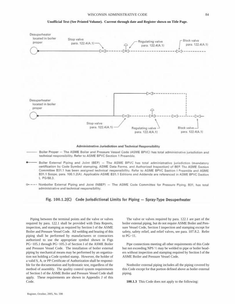
84WISCONSIN ADMINISTRATIVE CODE
Unofficial Text (See Printed Volume). Current through date and Register shown on Title Page.
Register, October, 2005, No. 598
Piping between the terminal points and the valve or valvesrequired by para. 122.1 shall be provided with Data Reports,inspection, and stamping as required by Section I of the ASMEBoiler and Pressure Vessel Code. All welding and brazing of thispiping shall be performed by manufacturers or contractorsauthorized to use the appropriate symbol shown in FigsPG−105.1 through PG−105.3 of Section I of the ASME Boilerand Pressure Vessel Code. The installation of boiler externalpiping by mechanical means may be performed by an organiza-tion not holding a Code symbol stamp. However, the holder ofa valid S, A, or PP Certificate of Authorization shall be responsi-ble for the documentation and hydrostatic test, regardless of themethod of assembly. The quality control system requirementsof Section I of the ASME Boiler and Pressure Vessel Code shallapply. These requirements are shown in Appendix J of thisCode.
The valve or valves required by para. 122.1 are part of theboiler external piping, but do not require ASME Boiler and Pres-sure Vessel Code, Section I inspection and stamping except forsafety, safety relief, and relief valves, see para. 107.8.2. Referto PG−11.
Pipe connections meeting all other requirements of this Codebut not exceeding NPS � may be welded to pipe or boiler head-ers without inspection and stamping required by Section I of theASME Boiler and Pressure Vessel Code.
Nonboiler external piping includes all the piping covered bythis Code except for that portion defined above as boiler externalpiping.
100.1.3 This Code does not apply to the following:

85 DEPARTMENT OF COMMERCE
Unofficial Text (See Printed Volume). Current through date and Register shown on Title Page.
Register, October, 2005, No. 598
(A) economizers, heaters, pressure vessels, and componentscovered by Sections of the ASME Boiler and Pressure VesselCode.
(B) building heating and distribution steam and condensatepiping designed for 15 psig [100 kPa (gage)] or less, or hot waterheating systems designed for 30 psig [200 kPa (gage)] or less.
(C) piping for hydraulic or pneumatic tools and their compo-nents downstream of the first block or stop valve off the systemdistribution header.
(D) piping for marine or other installations under Federalcontrol
(E) towers, building frames, tanks, mechanical equipment,instruments, and foundations.
104.1.3 Straight Pipe Under External Pressure
For determining wall thickness and stiffening requirementsfor straight pipe under external pressure, the procedures outlinedin UG−28, UG−29, and UG−30 of Section VIII, Division 1 of theASME Boiler and Pressure Vessel Code shall be followed.
104.2 Curved Segments of Pipes
104.2.1 Pipe Bends. Pipe bends shall be subject to the fol-lowing limitations:
(A) The minimum wall thickness shall meet the requirementsof para. 102.4.5 and the fabrication requirements of para. 129.
(B) For ferrous material, when the radius of a bend is 5 nomi-nal pipe diameter, or greater, and the nominal wall thickness ofthe pipe is schedule 40 or thicker, the difference between maxi-mum and minimum diameters shall not exceed 8% of averagemeasured outside diameters of the pipe before bending.
(C) Greater flattening may be permitted or less flatteningmay be required by the design, depending upon the service, thematerial, and the stress level involved.
104.2.2 Elbows. Elbows manufactured in accordance withthe standards listed in Table 126.1 are suitable for use at the pres-sure−temperature ratings specified by such standards, subject tothe requirements of para. 106.
104.3 Intersections
104.3.1 Branch Connections
(A) This paragraph gives rules governing the design ofbranch connections to sustain internal and external pressure incases where the axes of the branch and the run intersect, and theangle between the axes of the branch and of the run is between45 deg and 90 deg, inclusive.
Branch connections in which the smaller angle between theaxes of the branch and the run is less than 45 deg or branch con-nections where the axes of the branch and the run do not intersectimpose special design and fabrication problems. The rulesgiven herein may be used as a guide, but sufficient additionalstrength must be provided to assure safe service. Such branchconnections shall be designed to meet the requirement of para.104.7
(B) Branch connections in piping may be made from materi-als listed in Appendix A by the use of the following:
(B.1) fittings, such as tees, laterals, and crosses made inaccordance with the applicable standards listed in Table 126.1where the attachment of the branch pipe to the fitting is by buttwelding, socket welding, brazing, soldering, threading, or by aflanged connection.
(B.2) weld outlet fittings, such as cast or forged nozzles, cou-plings and adaptors, or similar items where the attachment of thebranch pipe to the fitting is by butt welding, socket welding,threading, or by a flanged connection. Such weld outlet fittingsare attached to the run by welding similar to that shown in Fig127.4.8(E). Couplings are restricted to the maximum of NPS 3.
(B.3) extruded outlets at right angles to the run pipe, in accor-dance with (G) below, where the attachment of the branch pipeis by butt welding.
(B.4) piping directly attached to the run pipe by welding inaccordance with para. 127.4.8 or by socket welding or threadingas stipulated below:
(B.4.1) socket welded right angle branch connections may bemade by attaching the branch pipe directly to the run pipe pro-vided
(B.4.1.1) the nominal size of the branch does not exceed NPS2 or one−fourth of the nominal size of the run, whichever issmaller.
(B.4.1.2) the depth of the socket measured at its minimumdepth in the run pipe is at least equal to that shown in ASMEB16.11. If the run pipe wall does not have sufficient thicknessto provide the proper depth of socket, an alternate type ofconstruction shall be used.
(B.4.1.3) the clearance between the bottom of the socket andthe end of the inserted branch pipe is in accordance with Fig.127.4.4(C).
(B4.1.4) the size of the fillet weld is not less than 1.09 timesthe nominal wall thickness of the branch type.
(B.4.2) threaded right angle branch connections may bemade by attaching the branch pipe directly to the run provided
(B.4.2.1) the nominal size of the branch does not exceed NPS2 or one−fourth of the nominal size of the run, whichever issmaller.
(B.4.2.2) the minimum thread engagement is: 6 full threadsfor NPS � and NPS � branches; 7 for NPS 1, NPS 1� and NPS1� branches; and 8 for NPS 2 branches. If the run pipe wall doesnot have sufficient thickness to provide the proper depth forthread engagement, an alternative type of construction shall beused.
(C) Branch Connections Not Requiring Reinforcement. Apipe having a branch connection is weakened by the openingthat must be made in it. Unless the wall thickness of the branchand/or run pipe is sufficiently in excess of that required to sustainthe pressure, it is necessary to provide additional material inorder to meet the reinforcement requirements of (D) and (E)below. However, there are certain branch connections for whichsupporting calculations are not required. These are as follows:

86WISCONSIN ADMINISTRATIVE CODE
Unofficial Text (See Printed Volume). Current through date and Register shown on Title Page.
Register, October, 2005, No. 598
(C.1) branch connections made by the use of a fitting (tee,lateral, cross, or branch weld−on fitting), manufactured in accor-dance with a standard listed in Table 126.1, and used within thelimits of pressure−temperature ratings specified in that standard.
(C.2) branch connections made by welding a coupling or halfcoupling directly to the run pipe in accordance with Fig.127.4.8(E) provided the nominal diameter of the branch does notexceed NPS 2 or one−fourth the nominal diameter of the run,whichever is less. The minimum wall thickness of the couplinganywhere in the reinforcement zone (if threads are in the zone,wall thickness is measured from the root of the thread to theminimum O.D.) shall not be less than that of the unthreadedbranch pipe. In no case shall the thickness of the coupling be lessthan extra heavy or Class 3000 rating.
Small branch connections NPS 2 or smaller as shown in Fig.127.4.8(F) may be used provided tw is not less than the thicknessof schedule 160 pipe of the branch size.
(C.3) integrally reinforced fittings welded directly to the runpipe when the reinforcements provided by the fitting and thedeposited weld metal meets the requirements of (D) below.
(C.4) integrally reinforced extruded outlets in the run pipe.The reinforcement requirements shall be in accordance with (G)below.
(D) Branch Connections Subject to Internal PressureRequiring Reinforcement.
(D.1) Reinforcement is required when it is not providedinherently in the components of the branch connection. Thisparagraph gives rules covering the design of branch connectionsto sustain internal pressure in cases where the angle between theaxes of the branch and of the run is between 45 deg and 90 deg.Subparagraph (E) below gives rules governing the design ofconnections to sustain external pressure.
(D.2) Figure 104.3.1(D) illustrates the notations used in thepressure−temperature design conditions of branch connectionsbut does not illustrate the allowances for mill tolerance or anyother wall thickness allowance. The designer shall make properallowances for the effects of corrosion or erosion, threading andgrooving, and mechanical strength as specified in paras.102.4.1, 102.4.2, and 102.4.4 in order that the required mini-mum reinforcement is assured over the design life of the pipingsystem. These notations are as follows:
a = angle between axes of branch and run, degb = subscript referring to branchDo = outside diameter of pipe, in. (mm)d1 = inside centerline longitudinal dimension of the finished
branch opening in the run of the pipe, in. (mm) = [Dob – 2(Tb – A)]/sin ad2 = “half width” of reinforcing zone, in. (mm) = the greater of d1 or (Tb – A) + (Th – A) + d1/2 but in no
case more than Doh, in. (mm)h = subscript referring to run or headerL4 = altitude of reinforcement zone outside of run, in. (mm) = 2.5(Tb – A) + tr or 2.5(Th – A), whichever is smallertr = thickness of attached reinforcing pad, in Example B, in.
(mm); or height of the largest 60 deg right triangle supported bythe run and branch outside diameter projected surfaces and lyingcompletely within the area of integral reinforcement, in Exam-ple C, in. (mm)
Tb, Th = actual (by measurement), or minimum wall thick-ness of the branch or header pipe, in. (mm), permissible underpurchase specification
tmb, tmh = required minimum wall thickness, in. (mm), of thebranch or header pipe as determined by use of Eq. (3) or (3A) inpara. 104.1.2(A)
(D.2.1) If the run pipe contains a longitudinal seam which isnot intersected by the branch, the stress value of seamless pipeof comparable grade may by used to determine the value of tmhfor the purpose of reinforcement calculations only. If the branchintersects a longitudinal weld in the run, or if the branch containsa weld, the weld joint efficiency for either or both shall enter thecalculations. If the branch and run both contain longitudinalwelds, care shall be taken to ensure that the two welds do notintersect each other.
(D.2.2) The required reinforcement area in square inches(square millimeters) for branch connections shall be the quantity
A7 = (tmh – A)d1 (2 − sin a)
For right angle connections the required reinforcementbecomes
A7 = (tmh – A)d1
The required reinforcement must be within the limits of thereinforcement zone as defined in (D.2.4) below.
(D.2.3) The reinforcement required by (D.2) shall be thatprovided by any combination of areas A1, A2, A3, A4, and A5,as defined below and illustrated in Fig. 104.3.1(D) where
A1 = area provided by excess pipe wall in the run = (2d2 – d1)(Th – tmh)A2 = area, in.2 (mm2), provided by excess pipe wall in the
branch for a distance L4 above the run = 2L4 (Tb – tmb)/sin aA3 = area provided by deposited weld metal beyond the out-
side diameter of the run and branch, and for fillet weld attach-ments of rings, pads, and saddles
A4 = area provided by a reinforcing ring, pad, or integralreinforcement. The value of A4 may be taken in the same mannerin which excess header metal is considered, provided the weldcompletely fuses the branch pipe, run pipe, and ring or pad, orintegral reinforcement. For welding branch connections refer topara. 127.4.8
A5 = area provided by a saddle on right angle connections = (O.D. of saddle – Dob)tr
Portions of the reinforcement area may be composed of mate-rials other than those of the run pipe, but if the allowable stressof these materials is less than that for the run pipe, the corre-sponding calculated reinforcement area provided by this mate-rial shall be reduced in the ratio of the allowable stress beingapplied to the reinforcement area. No additional credit shall betaken for materials having higher allowable stress values thanthe run pipe.
(D.2.4) Reinforcement Zone. The reinforcement zone is aparallelogram whose width shall extend a distance d2 on eachside of the centerline of the branch pipe, and whose altitude shallstart at the inside surface of the run pipe and extend to a distanceL4 from the outside surface of the run pipe.

87 DEPARTMENT OF COMMERCE
Unofficial Text (See Printed Volume). Current through date and Register shown on Title Page.
Register, October, 2005, No. 598

88WISCONSIN ADMINISTRATIVE CODE
Unofficial Text (See Printed Volume). Current through date and Register shown on Title Page.
Register, October, 2005, No. 598
(D.2.5) Reinforcement of Multiple Openings. It is preferredthat multiple branch openings be spaced so that their reinforce-ment zones do not overlap. If closer spacing is necessary, thefollowing requirement shall be met. The two or more openingsshall be reinforced in accordance with (D.2), with a combinedreinforcement that has a strength equal to the combined strengthof the reinforcement that would be required for the separateopenings. No portion of the cross section shall be considered asapplying to more than one opening, or be evaluated more thanonce in a combined area.
When more than two adjacent openings are to be providedwith a combined reinforcement, the minimum distance betweencenters of any two of these openings should preferably be at least1� times their average diameter, and the area of reinforcementbetween them shall be at least equal to 50% of the total requiredfor these two openings.
(D.2.6) Rings, Pads, and Saddles. Reinforcement providedin the form of rings, pads, or saddles shall not be appreciably nar-rower at the side than at the crotch.
A vent hole shall be provided at the ring, pad, or saddle to pro-vide venting during welding and heat treatment. Refer to para.127.4.8(E).
Rings, pads, or saddles may be made in more than one piece,provided the joints between pieces have full thickness welds,and each piece is provided with a vent hole.
(D.2.7) Other Designs. The adequacy of designs to whichthe reinforcement requirements of para. 104.3 cannot be appliedshall be proven by burst or proof tests on scale models or on fullsize structures, or by calculations previously substantiated bysuccessful service of similar design.
(E) Branch Connections Subject to External PressureRequiring Reinforcement. The reinforcement area in squareinches (square millimeters) required for branch connectionssubject to external pressure shall be
0.5tmhd1 (2 – sin a)
Procedures established heretofore for connections subject tointernal pressure shall apply for connections subject to externalpressure provided that Doh, Dob, and tr are reduced to compen-sate for external corrosion, if required by design conditions.
(F) Branch Connections Subject to External Forces andMoments. The requirements of the preceding paragraphs areintended to assure safe performance of a branch connection sub-jected only to pressure. However, when external forces andmoments are applied to a branch connection by thermal expan-sion and contraction, by dead weight of piping, valves, and fit-tings, covering and contents, or by earth settlement, the branchconnection shall be analyzed considering the stress intensifica-tion factors as specified in Appendix D. Use of ribs, gussets, andclamps designed in accordance with para. 104.3.4 is permissibleto stiffen the branch connection, but their areas cannot be

89 DEPARTMENT OF COMMERCE
Unofficial Text (See Printed Volume). Current through date and Register shown on Title Page.
Register, October, 2005, No. 598
counted as contributing to the required reinforcement area of thebranch connection.
(G) Extruded Outlets Integrally Reinforced
(G.1) The following definitions, modifications, notations,and requirements are specifically applicable to extruded outlets.The designer shall make proper wall thickness allowances inorder that the required minimum reinforcement is assured overthe design life of the system.
(G.2) Definition. An extruded outlet header is defined as aheader in which the extruded lip at the outlet has an altitudeabove the surface of the run which is equal to or greater than theradius of curvature of the external contoured portion of the out-let; i.e. ho ≥ ro. See nomenclature and Fig 104.3.1(G).
(G.3) These rules apply only to cases where the axis of theoutlet intersects and is perpendicular to the axis of the run. Theserules do not apply to any nozzle in which additional nonintegralmaterial is applied in the form of rings, pads, or saddles.
(G.4) The notation used herein is illustrated in Fig.104.3.1(G). All dimensions are in inches (millimeters).
d = outside diameter of branch pipedb = corroded internal diameter of branch pipeD = outside diameter of rundr = corroded internal diameter of rundc = corroded internal diameter of extruded outlet measured
at the level of the outside surface of the runho = height of the extruded lip. This must be equal to or
greater than ro, except as shown in (G.4.2) below.L8 = altitude of enforcement zone = 0.7 √dTotmb – A = required thickness of branch pipe according to wall
thickness Eq. (3) or (3A) in para. 104.1.2(A), but not includingany thickness for corrosion.
tb – A = actual thickness of branch wall not including corro-sion allowance
tmh – A = required thickness of the run according to the Eq.(3) or (3A) in para. 104.1.2(A), but not including any allowancefor corrosion
th – A = actual thickness of run wall, not including the corro-sion allowance
To = corroded finished thickness of extruded outlet measuredat a height equal to ro above the outside surface of the run
r1 = half width of reinforcement zone (equal to dc)ro = radius of curvature of external contoured portion of out-
let measured in the plane containing the axes of the run andbranch. This is subject to the following limitations:
(G.4.1) Minimum Radius. This dimension shall not be lessthan 0.05d except that on branch diameters larger than NPS 30,it need not exceed 1.50 in. (38 mm).
(G.4.2) Maximum Radius. For outlet pipe sizes 6 in. nominaland larger, this dimension shall not exceed 0.10d + 0.50 in.(0.10d + 12.7 mm). For outlet pipe sizes less than NPS 6, thisdimension shall not be greater than 1.25 in. (32 mm)
(G.4.3) When the external contour contains more than oneradius, the radius of any arc sector of approximately 45 deg shallmeet the requirements of (G.4.1) and (G.4.2) above. When the
external contour has a continuously varying radius, the radius ofcurvature at every point on the contour shall meet the require-ments of (G.4.1) and (G.4.2) above.
(G.4.4) Machining other than grinding for weld cleanup shallnot be employed in order to meet the above requirements.
(G.5) Required Area. The required area is defined as
A7 = K (tmh – A) dc
where K shall be taken as follows.
For d/D greater than 0.60,
K = 1.00
For d/D greater than 0.15 and not exceeding 0.60,
K = 0.6 + 2/3 d/D
For d/D equal to or less than 0.15,
K = 0.70
The design must meet criteria that the reinforcement areadefined in (G.6) below is not less than the required area.
(G.6) Reinforcement Area. The reinforcement area shall bethe sum of areas
A1 + A2 + A4
as defined below.
(G.6.1) Area A1 is the area lying within the reinforcementzone resulting from any excess thickness available in the runwall.
A1 = dc(tn − tmh)
(G.6.2) Area A2 is the area lying within the reinforcementzone resulting from any excess thickness available in the branchpipe wall.
A2 = 2L8(tb − tmb)
(G.6.3) Area A4 is the area lying within the reinforcementzone resulting from excess thickness available in the extrudedoutlet lip.
A4 = 2ro[To − (tb − A)]
(G.7) Reinforcement of Multiple Openings. It is preferredthat multiple branch openings be spaced so that their reinforce-ment zones do not overlap. If closer spacing is necessary, thefollowing requirements shall be met. The two or more openingsshall be reinforced in accordance with (G) with a combined rein-forcement that has a strength equal to the combined strength ofthe reinforcement that would be required for separate openings.No portion of the cross section shall be considered as applyingto more than one opening, or be evaluated more than once in acombined area.
(G.8) In addition to the above, the manufacturer shall beresponsible for establishing and marking on the section contain-ing extruded outlets, the design pressure and temperature. Themanufacturer’s name or trademarks shall be marked on the sec-tion.

90WISCONSIN ADMINISTRATIVE CODE
Unofficial Text (See Printed Volume). Current through date and Register shown on Title Page.
Register, October, 2005, No. 598

91 DEPARTMENT OF COMMERCE
Unofficial Text (See Printed Volume). Current through date and Register shown on Title Page.
Register, October, 2005, No. 598
104.3.3 Miters. Miter joints, and the terminology relatedthereto, are described in Appendix D. A widely spaced miterwith
� < 9 √tn/r deg
shall be considered to be equivalent to a girth butt−welded joint,and the rules of this paragraph do not apply. Miter joints, andfabricated pipe bends consisting of segments of straight pipewelded together, with � equal to or greater than this calculatedvalue may be used within the limitations described below.
(A) Pressure shall be limited to 10 psi (70 kPa) under the fol-lowing conditions.
(A.1) The assembly includes a miter weld with � > 22.5 deg,or contains a segment which has a dimension
B < 6tn
(A.2) The thickness of each segment of the miter is not lessthan that determined in accordance with para. 104.1.
(A.3) The contained fluid is nonflammable, non−toxic, andincompressible, except for gaseous vents to atmosphere.
(A.4) The number of full pressure cycles is less than 7,000during the expected lifetime of the piping system.
(A.5) Full penetration welds are used in joining miter seg-ments.
(B) Pressure shall be limited to 100 psi (700 kPa) under theconditions defined in (A.2), (A.3), (A.4), and (A.5) above, inaddition to the following:
(B.1) the angle � does not exceed 22.5 deg
(B.2) the assembly does not contain any segment which hasa dimension
B < 6tn
(C) Miters to be used in other services or at design pressuresabove 100 psi (700 kPa) shall meet the requirements of para.104.7.
(C.1) When justification under para. 104.7 is based on com-parable service conditions, such conditions must be establishedas comparable with respect to cyclic as well as static loadings.
(C.2) When justification under para. 104.7 is based on ananalysis, that analysis and substantiating tests shall consider thediscontinuity stresses which exist at the juncture between seg-ments; both for static (including brittle fracture) and cyclic inter-nal pressure.
(C.3) The wall thickness ts of a segment of a miter shall notbe less than specified in (C.3.1) or (C.3.2) below, depending onthe spacing.
(C.3.1) For closely−spaced miter bends (see Appendix D fordefinition)
2 − r/Rts = tm 2(1 − r/R)
(C.3.2) For widely−spaced miters (see Appendix D for defi-nition)
ts = tm(1 + 0.64√r/ts tan �)
(the above equation requires an iterative or quadratic solutionfor ts).
104.3.4 Attachments. External and internal attachments topiping shall be designed so as not to cause flattening of the pipe,excessive localized bending stresses, or harmful thermal gradi-ents in the pipe wall. It is important that such attachments bedesigned to minimize stress concentrations in applicationswhere the number of stress cycles, due either to pressure or ther-mal effect, is relatively large for the expected life of the equip-ment.
104.4 Closures
104.4.1 General. Closures for power piping systems shallmeet the applicable requirements of this Code and shall complywith the requirements described in (A) or (B) below. Closuremay be made
(A) by use of closure fittings, such as threaded or weldedplugs, caps, or blind flanges, manufactured in accordance withstandards listed in Table 126.1, and used within the specifiedpressure−temperature ratings, or
(B) in accordance with the rules contained in the ASMEBoiler and Pressure Vessel Code, Section I, Power Boilers,PG−31, or Section VIII, Pressure Vessels, Division 1, UG−34and UW−13, calculated from
tm = t + A
where
t = pressure design thickness, calculated for the given clo-sure shape and direction of loading using appropriate equationsand procedures in Section I or Section VIII, Division 1 of theASME Boiler and Pressure Vessel Code
The definition of A and the symbols used in determining t shallhave the definitions shown herein, instead of those given in theASME Boiler and Pressure Vessel Code.
Attachment of a welded flat permanent closure with only asingle fillet weld is not permitted.
104.4.2 Openings in Closures. Openings in closures maybe made by welding, extruding, or threading. Attachment to theclosure shall be in accordance with the limitations provided forsuch connections in para. 104.3.1 for branch connections. If thesize of the opening is greater than one−half of the inside diameterof the closure, the opening shall be designed as a reducer inaccordance with para. 104.6
Other openings in closures shall be reinforced in accordancewith the requirements of reinforcement for a branch connection.The total cross−sectional area required for reinforcement in anyplane passing through the center of the opening and normal tothe surface of the closure shall not be less than the quantity of d5t,where
d5 = diameter of the finished opening, in. (mm), and t asdefined in (B) above.
121.8 Structural Attachments
121.8.1 Nonintegral Type

92WISCONSIN ADMINISTRATIVE CODE
Unofficial Text (See Printed Volume). Current through date and Register shown on Title Page.
Register, October, 2005, No. 598
(A) Nonintegral attachments include clamps, slings, cradles,saddles, straps, and clevises.
(B) When clamps are used to support vertical lines, it is rec-ommended that shear lugs be welded to the pipe to prevent slip-page. The provisions of para. 121.8.2(B) shall apply.
(C) In addition to the provision of (B) above, clamps to sup-port vertical lines should be designed to support the total load oneither arm in the event the load shifts due to pipe and/or hangermovement.
121.8.2 Integral Type
(A) Integral attachments include ears, shoes, lugs, cylindricalattachments, rings, and skirts which are fabricated so that theattachment is an integral part of the piping component. Integralattachments shall be used in conjunction with restraints orbraces where multiaxial restraint in a single member is to bemaintained. Consideration shall be given to the localizedstresses induced into the piping component by the integralattachments. Where applicable, the conditions of para.128.8.1(C) are to apply.
(B) Integral lugs, plates, angle clips, etc., used as part of anassembly for the support or guiding of pipe may be weldeddirectly to the pipe provided the materials are compatible forwelding and the design is adequate for the temperature and load.The design of hanger lugs are attachment to piping for high tem-perature service shall be such as to provide for differentialexpansion between the pipe and the attached lug.
Welds shall be proportioned so that the shear stresses do notexceed either 0.8 times the applicable S values for the pipe mate-rial shown in the Allowable Stress Tables, or the allowable stressvalues determined in accordance with para. 121.2(A), (B), or(C). If materials for attachments have difference allowablestress values than the pipe, the lower allowable stress value ofthe two shall be used.
121.9 Loads and Supporting Structures
121.9.1 Considerations shall be give to the load carryingcapacity of equipment and the supporting structure. This maynecessitate closer spacing of hangers on lines with extremelyhigh loads.
121.10 Requirements for Fabricating Pipe Supports
121.10.1 Pipe supports shall be fabricated in accordancewith the requirements of para. 130.
PART 6SYSTEMS
122 DESIGN REQUIREMENTS PERTAINING TO SPE-CIFIC PIPING SYSTEMS
Except as specifically stated otherwise in this Part 6, all pro-visions of the Code apply fully to the piping systems describedherein.
122.1 Boiler External Piping; in Accordance with Para.100.1.2(A) − Steam, Feedwater, Blowoff, and Drain Piping
122.1.1 General. The minimum pressure and temperatureand other special requirements to be used in the design for steam,
feedwater, blowoff, and drain piping from the boiler to the valveor valves required by para. 122.1 shall be as specified in the fol-lowing paragraphs. Design requirements for desuperheaterspray piping connected to desuperheaters located in the boilerproper are provided in para 122.4.
(A) It is intended that the design pressure and temperature beselected sufficiently in excess of any expected operating condi-tions, not necessarily continuous, to permit satisfactory opera-tion without operation of the over−pressure protection devices.Also, since the operating temperatures of fired equipment canvary, the expected temperature at the connection to the firedequipment shall include the manufacturer’s maximum tempera-ture tolerance.
(B) In a forced flow steam generator with no fixed steam andwaterline, it is permissible to design the external piping, valves,and fittings attached to the pressure parts for different pressurelevels along the path through the steam generator of water−steam flow. The values of design pressure and the design tem-perature to be used for the external piping, valves, and fittingsshall be not less than that required for the expected maximumsustained operating pressure and temperature to which the abut-ted pressure part is subjected except when one or more of theoverpressure protection devices covered by PG−67.4 of SectionI of the ASME Boiler and Pressure Vessel Code is in operation.The steam piping shall comply with the requirements for themaximum sustained operating conditions as used in (A) above,or for the design throttle pressure plus 5%, whichever is greater.
(C) Provision shall be made for the expansion and contrac-tion of piping connected to boilers to limit forces and momentstransmitted to the boiler, by providing substantial anchorage atsuitable points, so that there shall be no undue strain transmittedto the boiler. Steam reservoirs shall be used on steam mainswhen heavy pulsations of the steam currents cause vibration.
(D) Piping connected to the outlet of a boiler for any purposeshall be attached by
(D.1) welding to a nozzle or socket welding fitting
(D.2) threading into a tapped opening with a threaded fittingor valve at the other end
(D.3) screwing each end into tapered flanges, fittings, orvalves with or without rolling or peening
(D.4) bolted joints including those of the Van Stone type
(D.5) blowoff piping of firetube boilers shall be attached inaccordance with (D.2) above if exposed to products of combus-tion or in accordance with (D.2), (D.3), or (D.4 above if not soexposed.
(E) Nonferrous pipe or tubes shall not exceed NPS 3 in diam-eter.
(F) American National Standard slip−on flanges shall notexceed NPS 4. Attachment of slip−on flanges shall be by doublefillet welds. The throats of the fillet welds shall not be less than0.7 times the thickness of the part to which the flange is attached.
(G) Hub−type flanges shall not be cut from plate material.
(H) American National Standard socket welded flanges maybe used in piping or boiler nozzles provided the dimensions do

93 DEPARTMENT OF COMMERCE
Unofficial Text (See Printed Volume). Current through date and Register shown on Title Page.
Register, October, 2005, No. 598
not exceed NPS 3 for Class 600 and lower and NPS 2� in Class1500.
122.1.2 Steam Fitting
(A) The value of P to be used in the formulas in para. 104 shallbe as follows:
(A.1) For steam piping connected to the steam drum or to thesuperheater inlet header up to the first stop valve in each connec-tion, the value of P shall be not less than the lowest pressure atwhich any drum safety valve is set to blow, and the S value shallnot exceed that permitted for the corresponding saturated seamtemperature.
(A.2) For steam piping connected to the superheater outletheader up to the first stop valve in each connection, the designpressure, except as otherwise provided in (A.4) below shall notbe less than the lowest pressure at which any safety valve on thesuperheater is set to blow, or not less than 85% of the lowest pres-sure at which any drum safety valve is set to blow, whichever isgreater, and the S value for the material used shall not exceed thatpermitted for the expected steam temperature.
(A.3) For steam piping between the first stop valve and thesecond valve, when one is required by para. 122.1.7, the designpressure shall be not less than the expected maximum sustainedoperating pressure of 85% of the lowest pressure at which anydrum safety valve is set to blow, whichever is greater, and the Svalue for the material used shall not exceed that permitted for theexpected steam temperature.
(A.4) For boilers installed on the unit system (i.e., one boilerand one turbine or other prime mover) and provided with auto-matic combustion control equipment responsive to steam headerpressure, the design pressure for the steam piping shall be notless than the design pressure at the throttle inlet plus 5%, or notless than 85% of the lowest pressure at which any drum safetyvalve is set to blow, or not less than the expected maximum sus-tained operating pressure at any point in the piping system,whichever is greater, and the S value for the material used shallnot exceed that permitted for the expected steam temperature atthe superheater outlet. For forced−flow steam generators withno fixed steam and waterline, the design pressure shall also beno less than the expected maximum sustained operating pres-sure.
(A.5) The design pressure shall not be taken at less than 100psig [700 kPa (gage)] for any condition of service or material.
122.1.3 Feedwater Piping
(A) The value of P to be used in the formulas in para. 104 shallbe as follows:
(A.1) For piping from the boiler to and including the requiredstop valve and the check valve, the minimum value of P exceptas permitted in para. 122.1.3(A.4) shall exceed the maximumallowable working pressure of the boiler by either 25% or 225psi (1550 kPa), whichever is the lesser. For an installation withan integral economizer without valves between the boiler andeconomizer, this paragraph shall apply only to the piping fromthe economizer inlet header to and including the required stopvalve and the check valve.
(A.2) For piping between the required check valve and theglobe or regulating valve, when required by para. 122.1.7(B),and including any bypass piping up to the shutoff valves in thebypass, the value of P shall be not less than the pressure requiredto feed the boiler.
(A.3) The value of P in the formula shall not be taken at lessthan 100 psig [700 kPa (gage)] for any condition of service ormaterial, and shall never be less than the pressure required tofeed the boiler.
(A.4) In a forced flow steam generator with no fixed steamand waterline, the value of P for feedwater piping from the boilerto and including the required stop valve may be in accordancewith the requirements of para. 122.1.1(B).
(B) The S value used, except as permitted in (A.4) above,shall not exceed that permitted for the temperature of saturatedsteam at the maximum allowable working pressure of the boiler.
(C) The size of the feed piping between the boiler and the firstrequired valve [para. 122.1.7(B)] or the branch feed connection[para. 122.1.7(B.4)] shall, as a minimum, be the same as theboiler connection.
122.1.4 Blowoff and Blowdown Piping. Blowoff and blow-down piping are defined as piping connected to a boiler and pro-vided with valves or cocks through which the water in the boilermay be blown out under pressure. This definition is not intendedto apply to (i) drain piping, and (ii) piping such as used on watercolumns, gage glasses, or feedwater regulators, etc., for the pur-pose of determining the operating condition of the equipment.Requirements for (i) and (ii) are described in paras. 122.1.5 and122.1.6. Blowoff systems are operated intermittently to removeaccumulated sediment from equipment and/or piping, or tolower boiler water level in a rapid manner. Blowdown systemsare primarily operated continuously to control the concentra-tions of dissolved solids in the boiler water.
(A) Blowoff piping systems from water spaces of a boiler, upto and including the blowoff valves, shall be designed in accord-ance with (A.1) to (A.4) below. Two shutoff valves are requiredin the blowoff system; specific valve requirements and excep-tions are given in para. 122.1.7(C).
(A.1) The value of P to be used in the formulas in para. 104shall exceed the maximum allowable working pressure of theboiler by either 25% or 225 psi (1550 kPa) whichever is less, butshall be not less than 100 psig [700 kPa (gage)].
(A.2) The allowable stress value for the piping materials shallnot exceed that permitted for the temperature of saturated steamat the maximum allowable working pressure of the boiler.
(A.3) All pipe shall be steel. Galvanized steel pipe and fit-tings shall not be used for blowoff piping. When the value of Pdoes not exceed 100 psig [700 kPa (gage)], the fittings shall bebronze, cast iron, malleable iron, ductile iron, or steel. When thevalue of P exceeds 100 psig [700 kPa (gage)], the fittings shallbe steel and the thickness of pipe and fittings shall not be lessthan that of Schedule 80 pipe.
(A.4) The size of blowoff piping shall be not less than the sizeof the connection on the boiler, and shall be in accordance withthe rules contained in the ASME Boiler and Pressure VesselCode, Section I, PG−59.3 and PEB−12.

94WISCONSIN ADMINISTRATIVE CODE
Unofficial Text (See Printed Volume). Current through date and Register shown on Title Page.
Register, October, 2005, No. 598
(B) The blowdown piping system from the boiler, to andincluding the shutoff valve, shall be designed in accordance with(B.1) through (B.4) below. Only one shutoff valve is requiredin the blowdown system.
(B.1) The value of P to be used in the formulas in para. 104shall be not less than the lowest set pressure of any safety valveon the boiler drum.
(B.2) The allowable stress value for the piping materials shallnot exceed that permitted for the temperature of saturated steamat the maximum allowable working pressure of the boiler.
(B.3) All pipe shall be steel. Galvanized steel pipe and fit-tings shall not be used for blowdown piping. When the value ofP does not exceed 100 psig [700 kPa (gage)], the fittings shallbe bronze, cast iron, malleable iron, ductile iron, or steel. Whenthe value of P exceeds 100 psig [700 kPa (gage)], the fittingsshall be steel and the thickness of pipe and fittings shall not beless than that of Schedule 80 pipe.
(B.4) The size of blowdown piping shall be not less than thesize of the connection on the boiler, and shall be in accordancewith the rules contained in the ASME Boiler and Pressure VesselCode, Section I, PG−59.3.
(C) The blowoff and blowdown piping beyond the requiredvalves described in (A) and (B) above are classified as nonboilerexternal piping. The requirements are given in para. 122.2.
122.1.5 Boiler Drains
(A) Complete drainage of the boiler and attached piping shallbe provided to the extent necessary to ensure proper operationof the steam supply system. The pipe, fittings, and valves of anydrain line shall not be smaller than the drain connection.
(B) If the drain lines are intended to be used both as drainsand as blowoffs, then two valves are required and all conditionsof paras. 122.1.4, 122.1.7(C), and 122.2 shall be met.
(C) When a drain is intended for use only when the boiler isnot under pressure (pressurizing the boiler for rapid drainage isan exception), a single shutoff valve is acceptable under the fol-lowing conditions: either the valve shall be a type that can belocked in the closed position or a suitable flanged and boltedconnection that accepts a blank insert shall be located on thedownstream side of the valve. When a single valve is used, itneed not be designed for blowoff service.
(D) Drain piping from the drain connection, including therequired valve(s) or the blanked flange connection, shall bedesigned for the temperature and pressure of the drain connec-tion. The remaining piping shall be designed for the expectedmaximum temperature and pressure. Static head and possiblechoked flow conditions shall be considered. In no case shall thedesign pressure and temperature be less than 100 psig [700 kPa(gage)] and 220�F (104�C), respectively.
122.1.6 Boiler External Piping − Miscellaneous Systems
(A) Materials, design, fabrication, examination, and erectionof piping for miscellaneous accessories, such as water level indi-cators, water columns, gage cocks, and pressure gages, shall bein accordance with the applicable sections of this Code.
(B) The value of P to be used in the Formulas in para. 104shall be not less than the maximum allowable working pressureof the boiler except as provided by para. 122.1.1(B).
(C) Valve requirements for water level indicators or watercolumns, special gage glass and gage cock requirements, mini-mum line sizes, and special piping configurations required spe-cifically for cleaning, access, or reliability shall be in accordancewith PG−60 of Section I of the ASME Boiler and Pressure VesselCode.
122.1.7 Valves and Fittings. The minimum pressure andtemperature rating for all valves and fittings in steam, feedwater,blowoff, and miscellaneous piping shall be equal to the pressureand temperature specified for the connected piping on the sidethat has the higher pressure, except that in no case shall the pres-sure be less than 100 psig [700 kPa (gage)], and for pressures notexceeding 100 psig [700 kPa (gage)] in feedwater and blowoffservice, the valves and fittings shall be equal at least to therequirement of the ASME standards for Class 125 cast iron orClass 150 steel.
(A) Steam Stop Valves. Each boiler discharge outlet, exceptsafety valve or safety relief valve connections, or reheater inletand outlet connections, shall be fitted with a stop valve locatedat an accessible point in the steam−delivery line and as near tothe boiler nozzle as is convenient and practicable.
(A.1) Boiler stop valves shall provide bidirectional shutoff atdesign conditions. The valve or valves shall meet the require-ments of para. 107. Valves with resilient (nonmetallic) seatsshall not be used where the boiler maximum allowable workingpressure exceeds 1,035 kPa (150 psig) or where the systemdesign temperature exceeds 186�C (366�F). Valves of the out-side screw and yoke, rising stem style are preferred. Valvesother than those of the outside screw and yoke, rising stem styleshall meet the following additional requirements.
(A.1.A) Each valve shall be equipped with a position indica-tor to visually indicate from a distance whether the valve is openor closed.
(A.1.B) Quarter turn valves shall be equipped with a slowoperating mechanism to minimize dynamic loadings on theboiler and attached piping.
(A.2) In the case of a single boiler and prime mover installa-tion, the stop valve required herein may be omitted provided theprime mover throttle valve is equipped with an indicator to showwhether it is opened or closed, and it is designed to withstand therequired boiler hydrostatic test.
(A.3) When two or more boilers are connected to a commonheader, or when a single boiler is connected to a header havinganother steam source, the connection from each boiler having aman−hole opening shall be fitted with two stop valves having anample free−blow drain between them. The preferred arrange-ment consists of one stop−check valve (located closest to theboiler) and one valve of the style and design described in (A.1)above. Alternatively, both valves may be of the style and designdescribed in (A.1) above.
When a second stop valve is required, it shall have a pressurerating at least equal to that required for the expected steam pres-sure and temperature at the valve, or a pressure rating at leastequal to 85% of the lowest set pressure of any safety valve on the
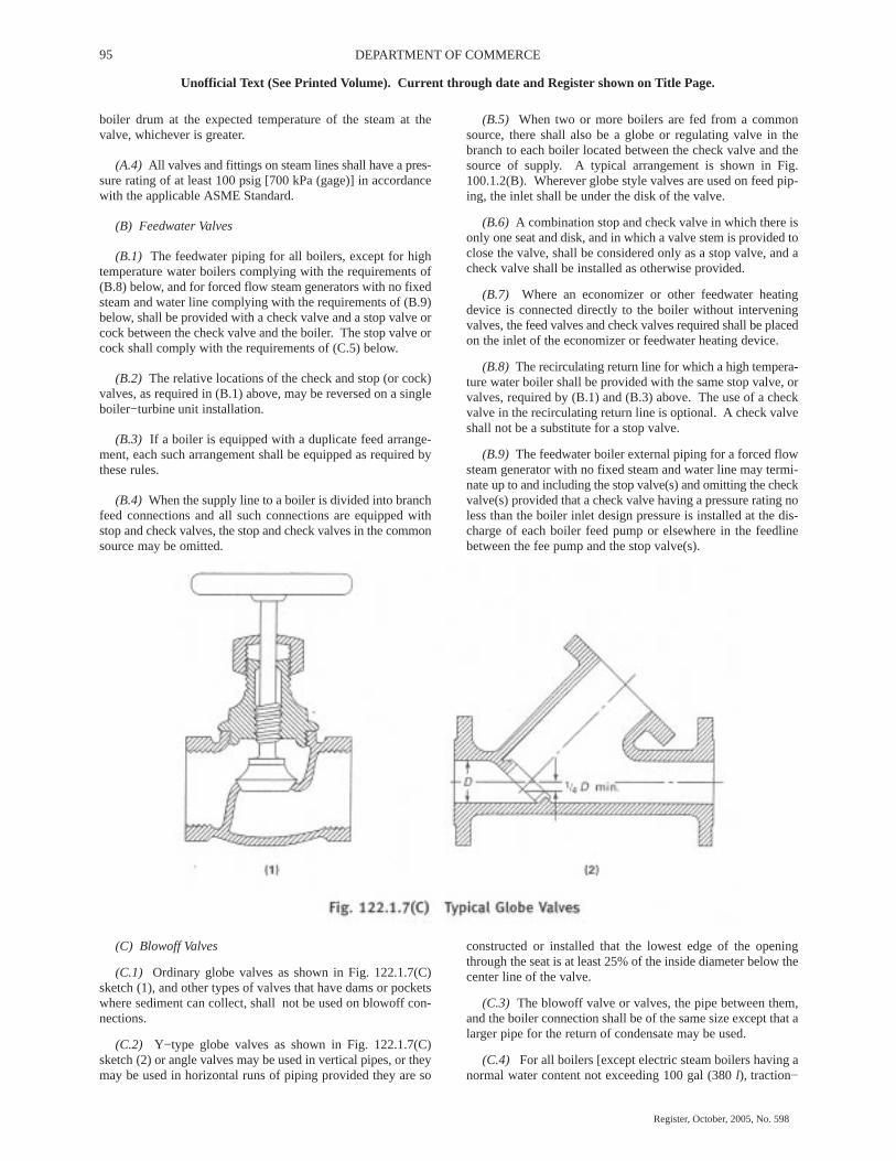
95 DEPARTMENT OF COMMERCE
Unofficial Text (See Printed Volume). Current through date and Register shown on Title Page.
Register, October, 2005, No. 598
boiler drum at the expected temperature of the steam at thevalve, whichever is greater.
(A.4) All valves and fittings on steam lines shall have a pres-sure rating of at least 100 psig [700 kPa (gage)] in accordancewith the applicable ASME Standard.
(B) Feedwater Valves
(B.1) The feedwater piping for all boilers, except for hightemperature water boilers complying with the requirements of(B.8) below, and for forced flow steam generators with no fixedsteam and water line complying with the requirements of (B.9)below, shall be provided with a check valve and a stop valve orcock between the check valve and the boiler. The stop valve orcock shall comply with the requirements of (C.5) below.
(B.2) The relative locations of the check and stop (or cock)valves, as required in (B.1) above, may be reversed on a singleboiler−turbine unit installation.
(B.3) If a boiler is equipped with a duplicate feed arrange-ment, each such arrangement shall be equipped as required bythese rules.
(B.4) When the supply line to a boiler is divided into branchfeed connections and all such connections are equipped withstop and check valves, the stop and check valves in the commonsource may be omitted.
(B.5) When two or more boilers are fed from a commonsource, there shall also be a globe or regulating valve in thebranch to each boiler located between the check valve and thesource of supply. A typical arrangement is shown in Fig.100.1.2(B). Wherever globe style valves are used on feed pip-ing, the inlet shall be under the disk of the valve.
(B.6) A combination stop and check valve in which there isonly one seat and disk, and in which a valve stem is provided toclose the valve, shall be considered only as a stop valve, and acheck valve shall be installed as otherwise provided.
(B.7) Where an economizer or other feedwater heatingdevice is connected directly to the boiler without interveningvalves, the feed valves and check valves required shall be placedon the inlet of the economizer or feedwater heating device.
(B.8) The recirculating return line for which a high tempera-ture water boiler shall be provided with the same stop valve, orvalves, required by (B.1) and (B.3) above. The use of a checkvalve in the recirculating return line is optional. A check valveshall not be a substitute for a stop valve.
(B.9) The feedwater boiler external piping for a forced flowsteam generator with no fixed steam and water line may termi-nate up to and including the stop valve(s) and omitting the checkvalve(s) provided that a check valve having a pressure rating noless than the boiler inlet design pressure is installed at the dis-charge of each boiler feed pump or elsewhere in the feedlinebetween the fee pump and the stop valve(s).
(C) Blowoff Valves
(C.1) Ordinary globe valves as shown in Fig. 122.1.7(C)sketch (1), and other types of valves that have dams or pocketswhere sediment can collect, shall not be used on blowoff con-nections.
(C.2) Y−type globe valves as shown in Fig. 122.1.7(C)sketch (2) or angle valves may be used in vertical pipes, or theymay be used in horizontal runs of piping provided they are so
constructed or installed that the lowest edge of the openingthrough the seat is at least 25% of the inside diameter below thecenter line of the valve.
(C.3) The blowoff valve or valves, the pipe between them,and the boiler connection shall be of the same size except that alarger pipe for the return of condensate may be used.
(C.4) For all boilers [except electric steam boilers having anormal water content not exceeding 100 gal (380 l), traction−

96WISCONSIN ADMINISTRATIVE CODE
Unofficial Text (See Printed Volume). Current through date and Register shown on Title Page.
Register, October, 2005, No. 598
purpose, and portable steam boilers; see (C.11) and (C.12)below] with allowable working pressure in excess of 100 psig[700 kPa (gage)], each bottom blowoff pipe shall have twoslow−opening valves, or one quick−opening valve or cock, at theboiler nozzle followed by a slow−opening valve. All valvesshall comply with the requirements of (C.5) and (C.6) below.
(C.5) When the value of P required by para. 122.1.4(A.1)does not exceed 250 psig [1750 kPa (gage)], the valves or cocksshall be bronze, cast iron, ductile iron, or steel. The valves orcocks, if of cast iron, shall not exceed NPS 2� and shall meet therequirements of the applicable ASME standard for Class 250, asgiven in Table 126.1, and if of bronze, steel, or ductile ironconstruction, shall meet the requirements of the applicable stan-dards as given in Table 126.1 or para. 124.6.
(C.6) When the value of P required by para. 122.1.4(A.1) ishigher than 250 psig [1750 kPa (gage)], the valves or cocks shallbe of steel construction equal at least to the requirements ofClass 300 of the applicable ASME standard listed in Table126.1. The minimum pressure rating shall be equal to the valueof P required by para. 122.1.4(A.1).
(C.7) If a blowoff cock is used, the plug shall be held in placeby a guard or gland. The plug shall be distinctly marked in linewith the passage.
(C.8) A slow−opening valve is a valve which requires at leastfive 360 deg turns of the operating mechanism to change fromfully closed to fully opened.
(C.9) On a boiler having multiple blowoff pipes, a singlemaster valve may be placed on the common blowoff pipe fromthe boiler, in which case only one valve on each individual blow-off is required. In such a case, either the master valve or the indi-vidual valves or cocks shall be of the slow−opening type.
(C.10) Two independent slow−opening valves, or a slow−opening valve and a quick−opening valve or cock, may be com-bined in one body and may be used provided the combined fit-ting is the equivalent of two independent slow−opening valves,or a slow−opening valve and a quick−opening valve or cock, andprovided further that the failure of one to operate cannot affectthe operation of the other.
(C.11) Only one blowoff valve, which shall be either a slow−opening or quick−opening blowoff valve or a cock, is requiredon traction and/or portable boilers.
(C.12) Only one blowoff valve, which shall be of a slow−opening type, is required on forced circulation and electricsteam boilers having a normal water content not exceeding 100gal (380 liter).
(D) Safety Valves
(D.1) Safety valves, relief valves, and safety relief valvesshall conform to the requirements of PG−67, PG−68, PG−69,PG−70, PG−71, PG−72, and PG−73 of Section I of the ASMEBoiler and Pressure Vessel Code.
Table 122.2Boiler or
Vessel PressureDesignPressure
DesignTemperature
psig kPa (gage) psig kPa (gage) �F �CBelow 250 1 750 Note (1) ... ...250−600 1 705−4 150 250 1 750 410 210601−900 4 151−6 200 400 2 750 450 230901−1,500 6 201−10 300 600 4 150 490 2551,501 and higher 10 301 and higher 900 6 200 535 280Note: (1) For boiler or vessel pressure(s) below 250 psig [1,750 kPa (gage)], the design pressure shall be determined in accordance with para. 122.1.4(B.1) but need not
exceed 250 psig [1,750 kPa (gage)].
122.2 Blowoff and Blowdown Piping in Nonboiler ExternalPiping
(A) From Boilers
(A.1) Blowoff piping, located between the valves describedin para. 122.1.4(A) and the blowoff tank or other point where thepressure is reduced approximately to atmospheric pressure andcannot be increased by closing a valve, shall be designed for sat-urated steam at the appropriate pressure and temperature inaccordance with Table 122.2. The provisions of para.122.1.4(A.3) shall apply.
(A.2) Blowdown piping, located after the valve described inpara. 122.1.4(B) in which the pressure cannot be increased byclosing a valve, shall be designed for the appropriate pressureand temperature in accordance with Table 122.2. The provisionsof para. 122.1.4(B.3) shall apply.
(A.3) When design pressure of Table 122.2 can be exceededdue either to closing of a downstream valve, calculated pressuredrop, or other means, the entire blowoff or blowdown pipingsystem shall be designed in accordance with para. 122.1.4(A) or(B), respectively.
(B) From Pressure Vessels Other Than Boilers
(B.1) The design pressure and temperature of the blowoffpiping from the pressure vessel to and including the blowoffvalve(s) shall be not less than the vessel design conditions.
122.3 Instrument, Control, and Sampling Piping
(A) The requirements of this Code, as supplemented by para.122.3, shall apply to the design of instrument, control, and sam-pling piping for the safe and proper operation of the piping itself.
(B) The term “Instrument Piping” shall apply to all valves,fittings, tubing, and piping used to connect instruments to mainpiping or to other instruments or apparatus or to measuringequipment as used within the classification of para. 100.1.
(C) The term “Control Piping” shall apply to all valves, fit-tings, tubing, and piping used to interconnect pneumatically orhydraulically operated control apparatus, also classified inaccordance with para. 100.1, as well as to signal transmissionsystems used to interconnect instrument transmitters and receiv-ers.
(D) The term “Sampling Piping” shall apply to all valves, fit-tings, tubing, and piping used for the collection of samples, suchas steam, water, oil, gas, and chemicals.

97 DEPARTMENT OF COMMERCE
Unofficial Text (See Printed Volume). Current through date and Register shown on Title Page.
Register, October, 2005, No. 598
(E) Paragraph 122.3 does not apply to tubing used in perma-nently closed systems, such as fluid−filled temperature respon-sive devices, or the temperature responsive devices themselves.
(F) Paragraph 122.3 does not apply to the devices, apparatus,measuring, sampling, signalling, transmitting, controlling,receiving, or collection instruments to which the piping is con-nected.
122.3.1 Materials and Design. The materials utilized forvalves, fittings, tubing, and piping shall meet the particular con-ditions of service and the requirements of the applicable specifi-cations listed under general paras. 105, 106, 107, and 108 withallowable stresses in accordance with the Allowable StressTables in Appendix A.
The materials for pressure retention components used forpiping specialties such as meters, tarps, and strainers in flam-mable, combustible, or toxic fluid systems shall in addition con-form to the requirements of paras. 122.7 and 122.8.
122.5 Pressure−Reducing Valves
122.5.1 General. Where pressure−reducing valves are used,one or more relief devices or safety valves shall be provided onthe low pressure side of the system. Otherwise, the piping andequipment on the low pressure side of the system shall bedesigned to withstand the upstream design pressure. The reliefor safety devices shall be located adjoining or as close as practi-cable to the reducing valve. The combined relieving capacityprovided shall be such that the design pressure of the low pres-sure system will not be exceeded if the reducing valve fails open.
122.5.2 Bypass Valves. Hand controlled bypass valves hav-ing a capacity no greater than the reducing valve may beinstalled around pressure reducing valves if the downstreampiping is protected by relief valves as required in para. 122.5.1or if the design pressure of the downstream piping system andequipment is at least as high as the upstream pressure.
122.5.3 Design of Valves and Relief Devices. Pressurereducing and bypass valves, and relief devices, shall be designedfor inlet pressure and temperature conditions. Safety and reliefvalves shall be in accordance with the requirements of para.107.8 of this Code.
122.6 Pressure Relief Piping
Pressure relief piping within the scope of this Code shall besupported to sustain reaction forces, and shall conform to therequirements of paras. 122.6.1 and 122.6.2.
122.6.1 Piping to Pressure−Relieving Safety Devices
(A) There shall be no intervening stop valve(s) between pip-ing being protected and the protective device(s).
(B) Diverter or changeover valves designed to allow servic-ing of redundant protective devices without system depressur-ization may be installed between the piping to be protected andthe required protective devices under the following conditions:
(B.1) Diverter or changeover valves are prohibited on boilerexternal piping or reheat piping.
(B.2) One hundred percent (100%) of the required relievingcapacity shall be continuously available any time the system isin service.
(B.3) Positive position indicators shall be provided ondiverter or changeover valves.
(B.4) Positive locking mechanisms and seals shall be pro-vided on diverter or changeover valves to preclude unauthorizedor accidental operation.
(B.5) Diverter or changeover valves shall be designed for themost severe conditions of pressure, temperature, and loading towhich they are exposed, and shall be in accordance with para.107.
(B.6) Provision shall be made to safely bleed off the pressurebetween the isolated protective device and the diverter orchangeover valve.
122.6.2 Discharge Piping From Pressure−RelievingSafety Devices
(A) There shall be no intervening stop valve between the pro-tective device or devices and the point of discharge.
(B) When discharging directly to the atmosphere, dischargeshall not impinge on other piping or equipment and shall bedirected away from platforms and other areas used by personnel.
(C) It is recommended that individual discharge lines beused, but if two or more reliefs are combined, the discharge pip-ing shall be designed with sufficient flow area to prevent blow-out of steam or other fluids. Sectional areas of a discharge pipeshall not be less than the full area of the valve outlets dischargingtherinto and the discharge pipe shall be as short and straight aspossible and so arranged as to avoid undue stresses on the valveor valves.
(D) Discharge lines from pressure−relieving safety deviceswithin the scope of this Code shall be designed to facilitatedrainage.
(E) When the umbrella or drip pan type of connection is used,the discharge piping shall be so designed as to prevent bindingdue to expansion movements.
(F) Drainage shall be provided to remove water collectedabove the safety valve seat.
(G) Carbon steel materials listed in Appendix A may be usedfor discharge piping which is subjected to temperatures above800�F (427�C) only during operation of pressure relievingsafety devices provided that
(G.1) the duration of pressure relieving safety device opera-tion is self−limiting
(G.2) the piping discharges directly to atmosphere
(G.3) the material allowable stresses at temperatures above800�F (427�C) shall be taken from Section II, Part D, Tables 1Aand 1B for materials applicable to Section I and Section VIII,Division 1 of the ASME Boiler and Pressure Vessel Code.

98WISCONSIN ADMINISTRATIVE CODE
Unofficial Text (See Printed Volume). Current through date and Register shown on Title Page.
Register, October, 2005, No. 598