executive summary jw marriott - pennsylvania state … kochalski ae thesis spring 2007 executive...
TRANSCRIPT
Greg Kochalski AE Thesis Spring 2007
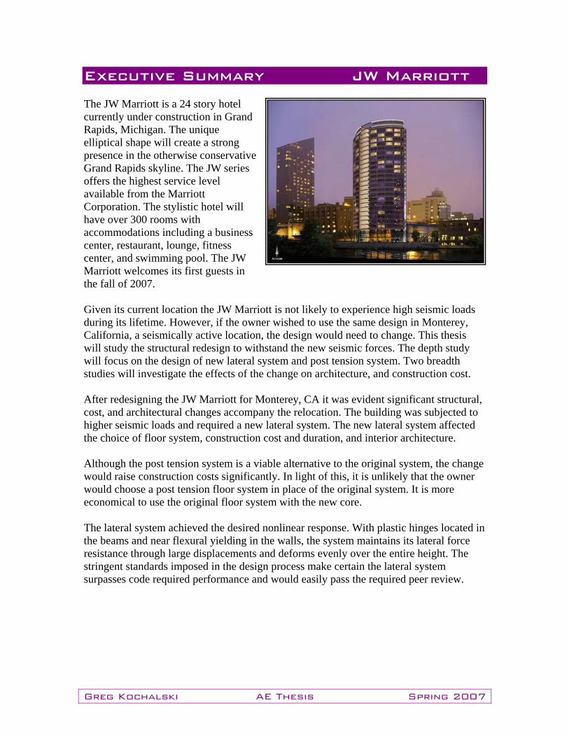
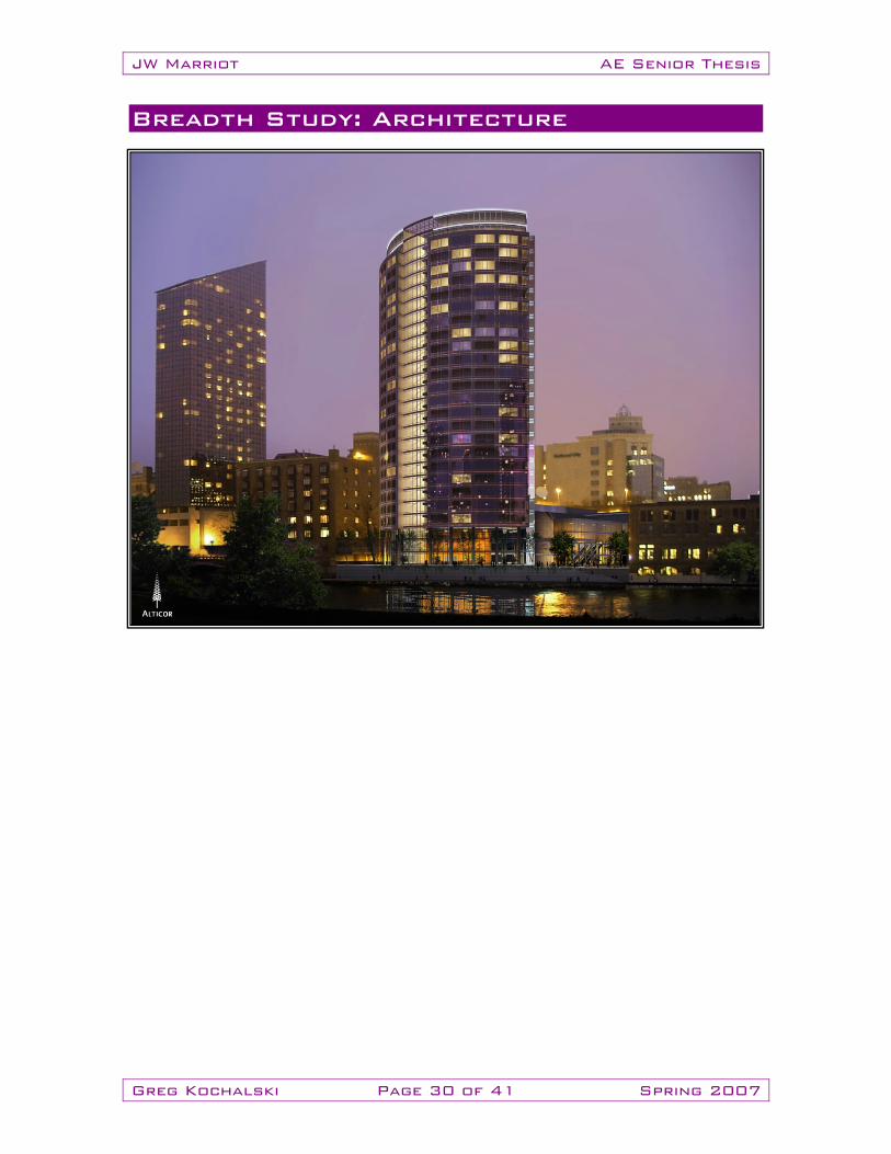
Executive Summary JW Marriott The JW Marriott is a 24 story hotel currently under construction in Grand Rapids, Michigan. The unique elliptical shape will create a strong presence in the otherwise conservative Grand Rapids skyline. The JW series offers the highest service level available from the Marriott Corporation. The stylistic hotel will have over 300 rooms with accommodations including a business center, restaurant, lounge, fitness center, and swimming pool. The JW Marriott welcomes its first guests in the fall of 2007. Given its current location the JW Marriott is not likely to experience high seismic loads during its lifetime. However, if the owner wished to use the same design in Monterey, California, a seismically active location, the design would need to change. This thesis will study the structural redesign to withstand the new seismic forces. The depth study will focus on the design of new lateral system and post tension system. Two breadth studies will investigate the effects of the change on architecture, and construction cost. After redesigning the JW Marriott for Monterey, CA it was evident significant structural, cost, and architectural changes accompany the relocation. The building was subjected to higher seismic loads and required a new lateral system. The new lateral system affected the choice of floor system, construction cost and duration, and interior architecture. Although the post tension system is a viable alternative to the original system, the change would raise construction costs significantly. In light of this, it is unlikely that the owner would choose a post tension floor system in place of the original system. It is more economical to use the original floor system with the new core. The lateral system achieved the desired nonlinear response. With plastic hinges located in the beams and near flexural yielding in the walls, the system maintains its lateral force resistance through large displacements and deforms evenly over the entire height. The stringent standards imposed in the design process make certain the lateral system surpasses code required performance and would easily pass the required peer review.
Table of Contents Introduction 1 Building information 2 Architecture 2 Project Delivery 2 Existing Structural Systems Description 3 Lateral force resisting system 4 Gravity system 4 Foundation 4 Structural Codes 5 Structural Depth Study Summary 6 Proposal summary 7 New Structural Codes 7 Depth: Lateral Force Resisting System 8 Introduction 9 Pier Review 9 Spectral Response Parameters 10 Analysis Methods and Assumptions 10 Preliminary Design 11 Static Force Analysis 12 Dynamic Force Analysis 13 Load Cases/Combinations 13 Lateral Forces 14 Accidental Torsion and Torsion Amplification 14 Pier and Spandrel Labeling 15 Coupling Beams 15 Story Drift 18 Shear Walls 20 Conclusion 23
Depth: Post Tension Floor System 24 Introduction 25 Analysis Methods and Assumptions 26 Design Loads 26 Punching Shear 27 Tendon Layout 27 Reinforcement 28 Deflections 28 Conclusion 29 Breadth Studies 30 Architecture 30 Construction Cost 36 Conclusions and Recommendations 39 Conclusion 40 Recommendations 40 Acknowledgements 41 Appendices 42 Appendix A: Existing Floor Plans Appendix B: Hand Calculations Appendix C: Redesign Floor Plans
JW Marriot AE Senior Thesis
Greg Kochalski Page 1 of 41 Spring 2007
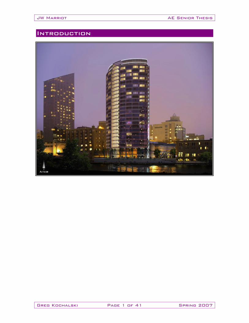
Introduction
JW Marriot AE Senior Thesis
Greg Kochalski Page 2 of 41 Spring 2007
Building Information: The JW Marriott (JWM) is a 24 story hotel currently under construction in Grand Rapids, Michigan. The unique elliptical shape will create a strong presence in the otherwise conservative Grand Rapids skyline. The JW series offers the highest service level available from the Marriott Corporation. The $95 million, 376,00 sf. complex will have over 300 rooms with accommodations include a business center, restaurant, lounge, 24 hour room service and concierge, an adjacent 550 space parking structure with a sky bridge, fitness/spa center, and swimming pool. The JW Marriott welcomes its first guests in the fall of 2007. Architecture: Lohan Caprile Goettsch Architects Inc. and BETA Design Group Inc. paired in designing this innovative new structure. Together they determined that eliminating the perimeter columns would create an appealing aesthetic effect without compromising structural integrity. The result is a unique elliptical shape offering a smooth touch of stylistic engineering to the otherwise conservative buildings that compose the Grand Rapids skyline. Reflective glass cladding helps to accentuate its place along the Grand River. The JW Marriott will be a multi-use development including a Parking Garage, Business Center, Restaurant/Lounge, and Fitness Center. The level of service will earn the ‘JW’ distinction that denotes the Marriott Corporation’s flagship line of hotels. Project Delivery: The project delivery method is complicated in parts due to the unique circumstances surrounding the project. Only trades such as fire protection and piping/ irrigation utilize a design build method. All other trades were bid out and awarded based on multiple reasons that did not only focus on lowest cost. Prior client relationships, most qualified, and locality were influential for subcontractor approval. Pepper Construction is under a construction management contract structure with the owner. Pepper was awarded the job on a negotiated basis and is locked in on a price for general conditions and fees.
Project Team: Owner: Alticor Inc. Architect: Goettsch Partners Associate Architect: BETA Design Group Interior Designer: Interior Solutions Curtain Wall: Antamax International Inc. Precast: Kerstra Precast Inc. Structural Steel: Steel Supply & Engineering Construction Manager: Pepper Construction
Group Contractor: Rockford Construction Co. Structural Engineer: Thornton Thomessetti
Engineers MEP/FP: Cosentini Associates Civil/Environmental Engineer: Fishbeck,
Thompson, Carr, Huber, Inc. Vertical Transportation: Desmond Associates Soil Testing: Materials Testing
Consultants Inc. Mini Piles: Nicholson Construction

JW Marriot AE Senior Thesis
Greg Kochalski Page 3 of 41 Spring 2007
Existing Structural Systems Description
JW Marriot AE Senior Thesis
Greg Kochalski Page 4 of 41 Spring 2007
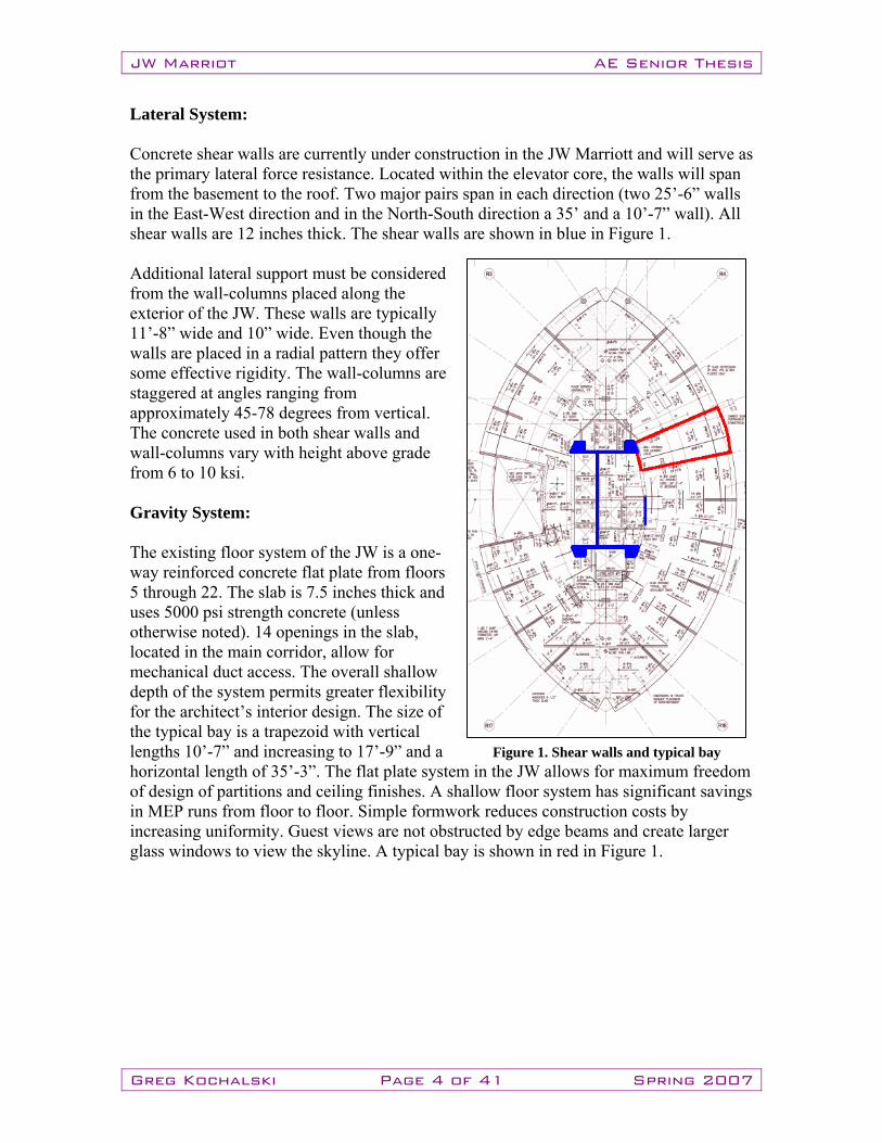
Lateral System: Concrete shear walls are currently under construction in the JW Marriott and will serve as the primary lateral force resistance. Located within the elevator core, the walls will span from the basement to the roof. Two major pairs span in each direction (two 25’-6” walls in the East-West direction and in the North-South direction a 35’ and a 10’-7” wall). All shear walls are 12 inches thick. The shear walls are shown in blue in Figure 1. Additional lateral support must be considered from the wall-columns placed along the exterior of the JW. These walls are typically 11’-8” wide and 10” wide. Even though the walls are placed in a radial pattern they offer some effective rigidity. The wall-columns are staggered at angles ranging from approximately 45-78 degrees from vertical. The concrete used in both shear walls and wall-columns vary with height above grade from 6 to 10 ksi. Gravity System: The existing floor system of the JW is a one-way reinforced concrete flat plate from floors 5 through 22. The slab is 7.5 inches thick and uses 5000 psi strength concrete (unless otherwise noted). 14 openings in the slab, located in the main corridor, allow for mechanical duct access. The overall shallow depth of the system permits greater flexibility for the architect’s interior design. The size of the typical bay is a trapezoid with vertical lengths 10’-7” and increasing to 17’-9” and a horizontal length of 35’-3”. The flat plate system in the JW allows for maximum freedom of design of partitions and ceiling finishes. A shallow floor system has significant savings in MEP runs from floor to floor. Simple formwork reduces construction costs by increasing uniformity. Guest views are not obstructed by edge beams and create larger glass windows to view the skyline. A typical bay is shown in red in Figure 1.
Figure 1. Shear walls and typical bay
JW Marriot AE Senior Thesis
Greg Kochalski Page 5 of 41 Spring 2007
Foundation: The foundation of the JW Marriott consists of multiple parts. A slab on grade covers the entire basement with 6 inches of 4000 psi concrete reinforced with WWF and 10 inches of 4000 psi concrete reinforced with 4#12 bars each way in the loading dock area. Grade beams travel between the building elevator core pile caps, a few exterior pile caps, and the perimeter of the basement crawl spaces. All grade beams are 6000si concrete reinforced top and bottom. Along the perimeter of the tower there are (21) piles that consist of (4-7) 200 ton micropiles. Each micropile is driven 19’ into the ground. In the elevator core there is a cache of (94) 200 ton micropiles,. Structural Codes:
• Building Code Michigan Building Code 2003. The 2003 Michigan Building Code is an adoption of the IBC 2003 with state amendments.
• Structural Concrete ACI 318-2002. Building Code Requirements for Structural Concrete.
• Concrete Masonry ACI 530-1999. Building Code Requirements for Masonry Structures.
• Structural Steel LRFD Specification for Structural Steel Buildings, 2nd Edition. AISC.
JW Marriot AE Senior Thesis
Greg Kochalski Page 6 of 41 Spring 2007
Structural Depth Study Summary
JW Marriot AE Senior Thesis
Greg Kochalski Page 7 of 41 Spring 2007
Proposal Summary: Proposal: Given its current location the JW Marriott is not likely to experience high seismic loads during its lifetime. If the owner wished to use the same design in Monterey, California, a seismically active location, the design will need to change. I propose to redesign the structure to withstand the forces conforming of the new seismically active site. Solution: The primary focus will be to keep as many characteristics the same for the new design. I will redesign the JW Marriott in accordance with ASCE7-05 and IBC2006 for Monterey, California. The main structural focus will be on the lateral force resisting system. Breadth Topics: There will be many affects on the JWM if significant changes must be made in the redesign for Monterey. Specifically, architecture and construction management topics will be compared and contrasted to the original design. Alternative floor plans for public and typical floors will be provided to exhibit the effects of the new system on architecture. A cost and schedule duration comparison will be studied in order to make a thorough conclusion concerning the new design. Structural Codes:
• Building Code IBC 2006. The 2003 Michigan Building Code, an adoption of the IBC 2003 was used for the original design. This will be updated to IBC 2006 for the redesign.
• Seismic Forces ASCE7-05. Seismic forces will be determined in accordance with the newest version of ASCE7 for the Monterey redesign.
• Structural Concrete ACI 318-2002. Building Code Requirements for Structural Concrete.
• Concrete Masonry ACI 530-1999. Building Code Requirements for Masonry Structures.
• Structural Steel LRFD Specification for Structural Steel Buildings, 2nd Edition. AISC.
JW Marriot AE Senior Thesis
Greg Kochalski Page 8 of 41 Spring 2007
Depth: Lateral Force Resisting System
JW Marriot AE Senior Thesis
Greg Kochalski Page 9 of 41 Spring 2007
Introduction: In order to resist the larger seismic forces it was necessary to create a new design for the entire resisting system. Previously, one large “I-shaped” section was used to resist lateral movement. A much larger section, or collection of sections, was needed to withstand the new forces. It was found that four smaller “I-shaped” sections connected using coupling beams was the best design option for the new location. The JWM redesign was penalized in numerous ways in order to guarantee an industry standard acceptable design that would easily pass peer review. The methods, assumptions, and results of the lateral system redesign are presented herein. Nonlinear response will be designed to have plastic hinging occur in only the coupling beams, the shear walls will be designed to incur only flexural yielding. If the shear walls are governed by flexural yielding they will maintain their lateral-force resistance through large displacements. The building will deform in a manner that distributes deformations over the height of the structure. This manner of nonlinear action will guarantee seismic force dissipation while maintaining the integrity of the structure. Peer Review: According to Section 12.2.5.4 of ASCE7 the building height limitation for special reinforced concrete shear walls is 240 ft. for structures in seismic design category D or E. The JWM exceeds the height limitation at 256 ft and will require peer review per Section 16.2.5. The JWM will be subjected to the following considerations during peer review:
1. Review of acceptance criteria used to demonstrate the adequacy of structural elements and systems to withstand the calculated force and deformation demands, together with that laboratory and other data used to substantiate these criteria.
2. Review of the preliminary design including the selection of structural system and the configuration of structural elements.
3. Review of the final design of the entire structural system and all supporting analyses.
In order to insure an expeditious peer review measures will be taken to design the lateral system to exceed code requirements and limitations. The Maximum Considered Earthquake (MCE) will be for a 1000 year event, much greater than the code required MCE of a 50 year event. In addition, flexure and shear capacities will be designed much greater than code requirements.
JW Marriot AE Senior Thesis
Greg Kochalski Page 10 of 41 Spring 2007
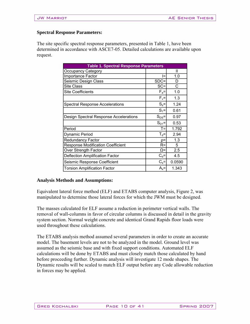
Spectral Response Parameters: The site specific spectral response parameters, presented in Table 1, have been determined in accordance with ASCE7-05. Detailed calculations are available upon request.
III= 1.0
SDC= DSC= CFa= 1.0Fv= 1.3Ss= 1.24S1= 0.61
SDS= 0.97SD1= 0.53
T= 1.792Td= 2.94ρ= 1.3R= 5Ω= 2.5
Cd= 4.5Cs= 0.0590Ax= 1.343
Table 1. Spectral Response ParametersOccupancy CategoryImportance FactorSeismic Design ClassSite ClassSite Coefficients
Spectral Response Accelerations
Design Spectral Response Accelerations
Period
Deflection Amplification FactorSeismic Response CoefficientTorsion Amplification Factor
Dynamic PeriodRedundancy FactorResponse Modification Coefficient Over Strength Factor
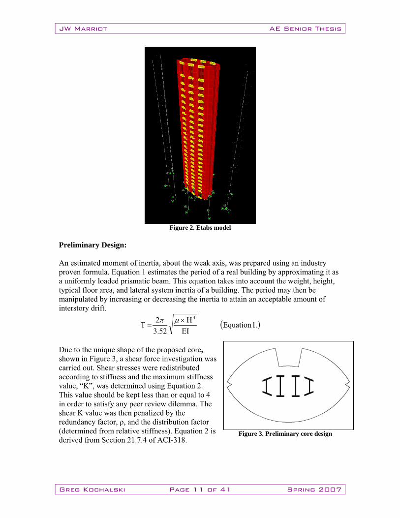
Analysis Methods and Assumptions: Equivalent lateral force method (ELF) and ETABS computer analysis, Figure 2, was manipulated to determine those lateral forces for which the JWM must be designed. The masses calculated for ELF assume a reduction in perimeter vertical walls. The removal of wall-columns in favor of circular columns is discussed in detail in the gravity system section. Normal weight concrete and identical Grand Rapids floor loads were used throughout these calculations. The ETABS analysis method assumed several parameters in order to create an accurate model. The basement levels are not to be analyzed in the model. Ground level was assumed as the seismic base and with fixed support conditions. Automated ELF calculations will be done by ETABS and must closely match those calculated by hand before proceeding further. Dynamic analysis will investigate 12 mode shapes. The Dynamic results will be scaled to match ELF output before any Code allowable reduction in forces may be applied.
JW Marriot AE Senior Thesis
Greg Kochalski Page 11 of 41 Spring 2007
Figure 2. Etabs model
Preliminary Design: An estimated moment of inertia, about the weak axis, was prepared using an industry proven formula. Equation 1 estimates the period of a real building by approximating it as a uniformly loaded prismatic beam. This equation takes into account the weight, height, typical floor area, and lateral system inertia of a building. The period may then be manipulated by increasing or decreasing the inertia to attain an acceptable amount of interstory drift.
( ).1EquationEI
H52.3
2T4×
=μπ
Due to the unique shape of the proposed core, shown in Figure 3, a shear force investigation was carried out. Shear stresses were redistributed according to stiffness and the maximum stiffness value, “K”, was determined using Equation 2. This value should be kept less than or equal to 4 in order to satisfy any peer review dilemma. The shear K value was then penalized by the redundancy factor, ρ, and the distribution factor (determined from relative stiffness). Equation 2 is derived from Section 21.7.4 of ACI-318.
Figure 3. Preliminary core design
JW Marriot AE Senior Thesis
Greg Kochalski Page 12 of 41 Spring 2007
( ).2Equation4 DF'A
/K ≤
⎥⎥⎦
⎤
⎢⎢⎣
⎡××= ρ
φ
cv
uVave f
V
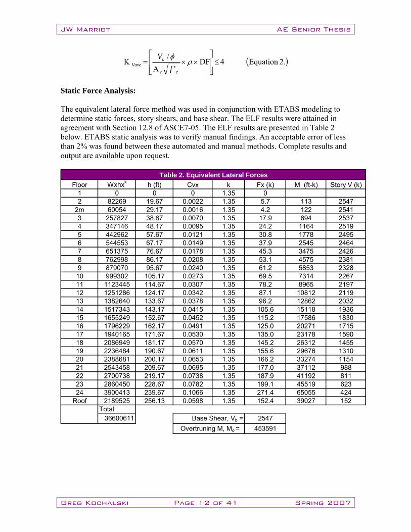
Static Force Analysis: The equivalent lateral force method was used in conjunction with ETABS modeling to determine static forces, story shears, and base shear. The ELF results were attained in agreement with Section 12.8 of ASCE7-05. The ELF results are presented in Table 2 below. ETABS static analysis was to verify manual findings. An acceptable error of less than 2% was found between these automated and manual methods. Complete results and output are available upon request.
Floor Wxhxk h (ft) Cvx k Fx (k) M (ft-k) Story V (k)1 0 0 0 1.35 02 82269 19.67 0.0022 1.35 5.7 113 2547
2m 60054 29.17 0.0016 1.35 4.2 122 25413 257827 38.67 0.0070 1.35 17.9 694 25374 347146 48.17 0.0095 1.35 24.2 1164 25195 442962 57.67 0.0121 1.35 30.8 1778 24956 544553 67.17 0.0149 1.35 37.9 2545 24647 651375 76.67 0.0178 1.35 45.3 3475 24268 762998 86.17 0.0208 1.35 53.1 4575 23819 879070 95.67 0.0240 1.35 61.2 5853 232810 999302 105.17 0.0273 1.35 69.5 7314 226711 1123445 114.67 0.0307 1.35 78.2 8965 219712 1251286 124.17 0.0342 1.35 87.1 10812 211913 1382640 133.67 0.0378 1.35 96.2 12862 203214 1517343 143.17 0.0415 1.35 105.6 15118 193615 1655249 152.67 0.0452 1.35 115.2 17586 183016 1796229 162.17 0.0491 1.35 125.0 20271 171517 1940165 171.67 0.0530 1.35 135.0 23178 159018 2086949 181.17 0.0570 1.35 145.2 26312 145519 2236484 190.67 0.0611 1.35 155.6 29676 131020 2388681 200.17 0.0653 1.35 166.2 33274 115421 2543458 209.67 0.0695 1.35 177.0 37112 98822 2700738 219.17 0.0738 1.35 187.9 41192 81123 2860450 228.67 0.0782 1.35 199.1 45519 62324 3900413 239.67 0.1066 1.35 271.4 65055 424
Roof 2189525 256.13 0.0598 1.35 152.4 39027 152Total
36600611 2547453591
Base Shear, Vb = Overtruning M, Mo =
Table 2. Equivalent Lateral Forces
JW Marriot AE Senior Thesis
Greg Kochalski Page 13 of 41 Spring 2007
Dynamic Force Analysis: The modal response spectrum analysis was completed in accordance with Section 12.9 of ASCE7-05. In order to attain the required 90% of mass participation in orthogonal response, a minimum of 7 modes needed consideration. 12 modes were investigated thus exceeding minimum requirements. Story drifts were concluded in accordance with Section 12.9.2; an additional response spectrum case was created to consider only drift. Scaling design values of dynamic base shear were prepared per Section 12.9.3. The code allowable 85% reduction was applied to ELF:Dynamic base shear ratio to determine forces. Accidental torsion affects were included in the model, thus, torsion amplification was not required. The soil structure interaction reduction, per Section 12.9.7, was not used in evaluating the model. Cases/Combinations: AUTOEXZ1: Automated ETABS static force analysis. Forces act along the X axis with a positive eccentricity along the Y axis. This creates a moment with a positive sign convention. AUTOEXZ2: Automated ETABS static force analysis. Forces act along the X axis with a negative eccentricity along the Y axis. This creates a moment with a negative sign convention. AUTOEYZ1: Automated ETABS static force analysis. Forces act along the Y axis with a positive eccentricity along the X axis. This creates a moment with a positive sign convention. AUTOEYZ2: Automated ETABS static force analysis. Forces act along the Y axis with a negative eccentricity along the X axis. This creates a moment with a negative sign convention. XSPECD: Spectral response in the X direction using a 5% damping ratio. This response case is to be used in determining displacements, not forces. The modal combination uses the Complete Quadratic Combination (CQC) method. This combination considers coupling between closely spaced modes caused by modal damping. The directional combination uses the Square Root of the Sum of Squares method (SRSS). This method does not take into account any modal coupling. Amplification of torsion is accounted for by modifying the eccentricity ratio. The input response spectra scale factor was determined by using equation 3, shown below.
( ).3Equation386FactorScaledC
R×=
XSPECF: Spectral response in the X direction using a 5% damping ratio. This response case is to be used in determining forces, not displacements. The modal combination uses the Complete Quadratic Combination (CQC) method. This combination considers coupling between closely spaced modes caused by modal damping. The directional
JW Marriot AE Senior Thesis
Greg Kochalski Page 14 of 41 Spring 2007
combination uses the Square Root of the Sum of Squares method (SRSS). This method does not take into account any modal coupling. Amplification of torsion is accounted for by modifying the eccentricity ratio. The input response spectra scale factor was determined by using equation 4, shown below.
( ) ( ).4Equation85.0S.F.FactorScaleDYN
ELFDYN ×⎟
⎟⎠
⎞⎜⎜⎝
⎛×=
b
b
VV
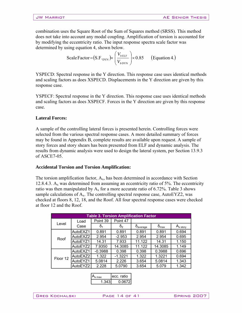
YSPECD: Spectral response in the Y direction. This response case uses identical methods and scaling factors as does XSPECD. Displacements in the Y direction are given by this response case. YSPECF: Spectral response in the Y direction. This response case uses identical methods and scaling factors as does XSPECF. Forces in the Y direction are given by this response case. Lateral Forces: A sample of the controlling lateral forces is presented herein. Controlling forces were selected from the various spectral response cases. A more detailed summary of forces may be found in Appendix B, complete results are available upon request. A sample of story forces and story shears has been presented from ELF and dynamic analysis. The results from dynamic analysis were used to design the lateral system, per Section 13.9.3 of ASCE7-05. Accidental Torsion and Torsion Amplification: The torsion amplification factor, Ax, has been determined in accordance with Section 12.8.4.3. Ax was determined from assuming an eccentricity ratio of 5%. The eccentricity ratio was then manipulated by Ax for a more accurate ratio of 6.72%. Table 3 shows sample calculations of Ax. The controlling spectral response case, AutoEYZ2, was checked at floors 8, 12, 18, and the Roof. All four spectral response cases were checked at floor 12 and the Roof.
Point 39 Point 47δ1 δ2 δaverage δmax Ax story
AutoEXZ1 0.891 0.891 0.891 0.891 0.694AutoEXZ2 2.954 -2.953 2.954 2.954 0.695AutoEYZ1 14.31 7.933 11.122 14.31 1.150AutoEYZ2 7.9350 14.3085 11.122 14.3085 1.149AutoEXZ1 -0.3988 0.398 0.398 0.3988 0.696AutoEXZ2 1.322 -1.3221 1.322 1.3221 0.694AutoEYZ1 5.0814 2.226 3.654 5.0814 1.343AutoEYZ2 2.228 5.0790 3.654 5.079 1.342
Ax max ecc. ratio1.343 0.0672
Roof
Floor 12
Table 3. Torsion Amplification Factor
Level Load Case
JW Marriot AE Senior Thesis
Greg Kochalski Page 15 of 41 Spring 2007
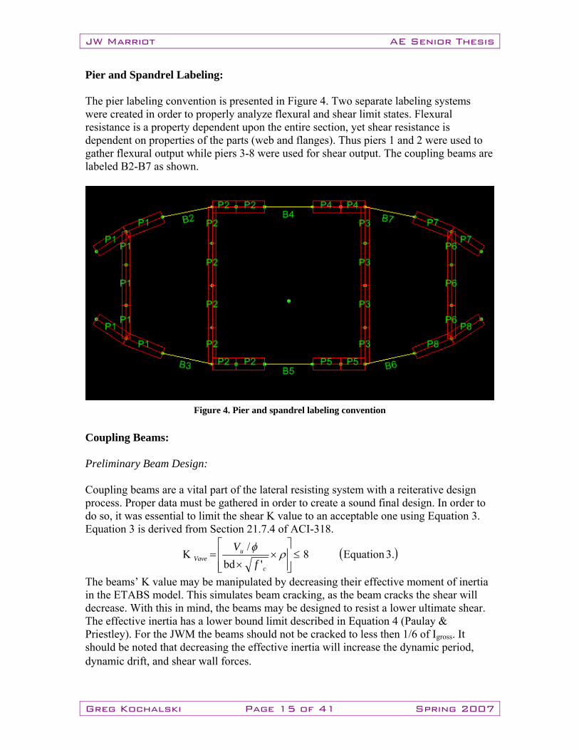
Pier and Spandrel Labeling: The pier labeling convention is presented in Figure 4. Two separate labeling systems were created in order to properly analyze flexural and shear limit states. Flexural resistance is a property dependent upon the entire section, yet shear resistance is dependent on properties of the parts (web and flanges). Thus piers 1 and 2 were used to gather flexural output while piers 3-8 were used for shear output. The coupling beams are labeled B2-B7 as shown.
Coupling Beams: Preliminary Beam Design: Coupling beams are a vital part of the lateral resisting system with a reiterative design process. Proper data must be gathered in order to create a sound final design. In order to do so, it was essential to limit the shear K value to an acceptable one using Equation 3. Equation 3 is derived from Section 21.7.4 of ACI-318.
( ).3Equation8 'bd
/K ≤
⎥⎥⎦
⎤
⎢⎢⎣
⎡×
×= ρ
φ
c
uVave f
V
The beams’ K value may be manipulated by decreasing their effective moment of inertia in the ETABS model. This simulates beam cracking, as the beam cracks the shear will decrease. With this in mind, the beams may be designed to resist a lower ultimate shear. The effective inertia has a lower bound limit described in Equation 4 (Paulay & Priestley). For the JWM the beams should not be cracked to less then 1/6 of Igross. It should be noted that decreasing the effective inertia will increase the dynamic period, dynamic drift, and shear wall forces.
Figure 4. Pier and spandrel labeling convention
JW Marriot AE Senior Thesis
Greg Kochalski Page 16 of 41 Spring 2007
( )( ) ( ).4EquationI/31
2.0I gross2effective ×+
≥nlh
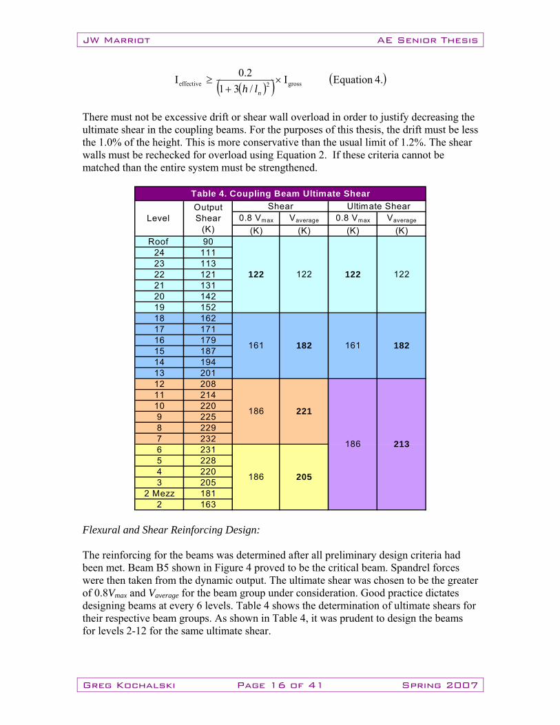
There must not be excessive drift or shear wall overload in order to justify decreasing the ultimate shear in the coupling beams. For the purposes of this thesis, the drift must be less the 1.0% of the height. This is more conservative than the usual limit of 1.2%. The shear walls must be rechecked for overload using Equation 2. If these criteria cannot be matched than the entire system must be strengthened.
0.8 Vmax Vaverage 0.8 Vmax Vaverage
(K) (K) (K) (K)Roof 90
24 11123 11322 12121 13120 14219 15218 16217 17116 17915 18714 19413 20112 20811 21410 2209 2258 2297 2326 2315 2284 2203 205
2 Mezz 1812 163
Table 4. Coupling Beam Ultimate Shear
186 205
Ultimate Shear
122 122
161 182
186 213
161 182
186 221
Level Output Shear
(K)
Shear
122 122
Flexural and Shear Reinforcing Design: The reinforcing for the beams was determined after all preliminary design criteria had been met. Beam B5 shown in Figure 4 proved to be the critical beam. Spandrel forces were then taken from the dynamic output. The ultimate shear was chosen to be the greater of 0.8Vmax and Vaverage for the beam group under consideration. Good practice dictates designing beams at every 6 levels. Table 4 shows the determination of ultimate shears for their respective beam groups. As shown in Table 4, it was prudent to design the beams for levels 2-12 for the same ultimate shear.
JW Marriot AE Senior Thesis
Greg Kochalski Page 17 of 41 Spring 2007
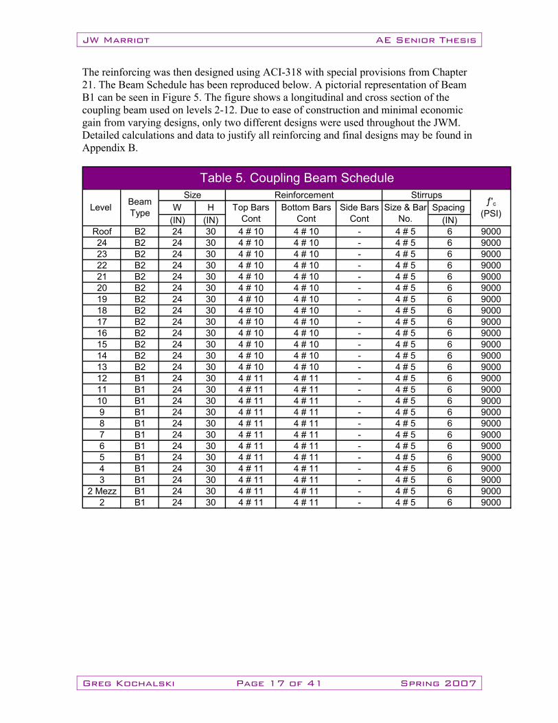
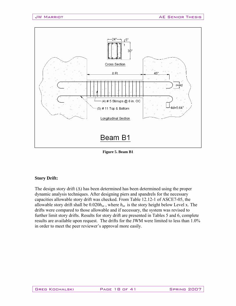
The reinforcing was then designed using ACI-318 with special provisions from Chapter 21. The Beam Schedule has been reproduced below. A pictorial representation of Beam B1 can be seen in Figure 5. The figure shows a longitudinal and cross section of the coupling beam used on levels 2-12. Due to ease of construction and minimal economic gain from varying designs, only two different designs were used throughout the JWM. Detailed calculations and data to justify all reinforcing and final designs may be found in Appendix B.
W H Spacing (IN) (IN) (IN)
Roof B2 24 30 4 # 5 6 900024 B2 24 30 4 # 5 6 900023 B2 24 30 4 # 5 6 900022 B2 24 30 4 # 5 6 900021 B2 24 30 4 # 5 6 900020 B2 24 30 4 # 5 6 900019 B2 24 30 4 # 5 6 900018 B2 24 30 4 # 5 6 900017 B2 24 30 4 # 5 6 900016 B2 24 30 4 # 5 6 900015 B2 24 30 4 # 5 6 900014 B2 24 30 4 # 5 6 900013 B2 24 30 4 # 5 6 900012 B1 24 30 4 # 5 6 900011 B1 24 30 4 # 5 6 900010 B1 24 30 4 # 5 6 90009 B1 24 30 4 # 5 6 90008 B1 24 30 4 # 5 6 90007 B1 24 30 4 # 5 6 90006 B1 24 30 4 # 5 6 90005 B1 24 30 4 # 5 6 90004 B1 24 30 4 # 5 6 90003 B1 24 30 4 # 5 6 9000
2 Mezz B1 24 30 4 # 5 6 90002 B1 24 30 4 # 5 6 9000
----
----
----
4 # 114 # 114 # 114 # 11
4 # 114 # 114 # 114 # 11
4 # 114 # 114 # 114 # 11
4 # 114 # 114 # 114 # 11
4 # 114 # 114 # 114 # 11
4 # 114 # 114 # 114 # 11
----
----
----
4 # 104 # 104 # 104 # 10
4 # 104 # 104 # 104 # 10
4 # 104 # 104 # 104 # 10
4 # 104 # 104 # 104 # 10
4 # 104 # 104 # 104 # 10
4 # 104 # 104 # 104 # 10
Stirrupsƒ'c
(PSI)
Table 5. Coupling Beam Schedule
Size & Bar No.
Bottom Bars Cont
Side Bars Cont
Reinforcement
4 # 10 4 # 10 -
Level Beam Type
SizeTop Bars
Cont
JW Marriot AE Senior Thesis
Greg Kochalski Page 18 of 41 Spring 2007
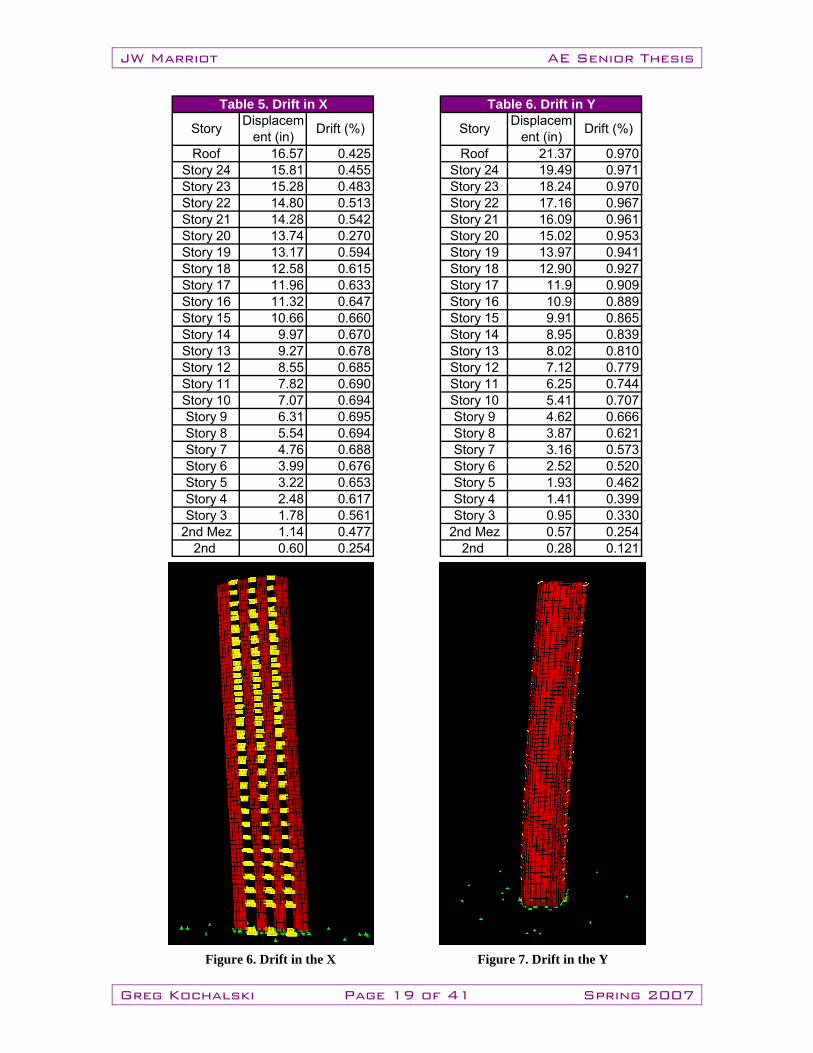
Story Drift: The design story drift (Δ) has been determined has been determined using the proper dynamic analysis techniques. After designing piers and spandrels for the necessary capacities allowable story drift was checked. From Table 12.12-1 of ASCE7-05, the allowable story drift shall be 0.020hsx , where hsx is the story height below Level x. The drifts were compared to those allowable and if necessary, the system was revised to further limit story drifts. Results for story drift are presented in Tables 5 and 6, complete results are available upon request. The drifts for the JWM were limited to less than 1.0% in order to meet the peer reviewer’s approval more easily.
Figure 5. Beam B1
JW Marriot AE Senior Thesis
Greg Kochalski Page 19 of 41 Spring 2007
Roof 16.57 0.425 Roof 21.37 0.970Story 24 15.81 0.455 Story 24 19.49 0.971Story 23 15.28 0.483 Story 23 18.24 0.970Story 22 14.80 0.513 Story 22 17.16 0.967Story 21 14.28 0.542 Story 21 16.09 0.961Story 20 13.74 0.270 Story 20 15.02 0.953Story 19 13.17 0.594 Story 19 13.97 0.941Story 18 12.58 0.615 Story 18 12.90 0.927Story 17 11.96 0.633 Story 17 11.9 0.909Story 16 11.32 0.647 Story 16 10.9 0.889Story 15 10.66 0.660 Story 15 9.91 0.865Story 14 9.97 0.670 Story 14 8.95 0.839Story 13 9.27 0.678 Story 13 8.02 0.810Story 12 8.55 0.685 Story 12 7.12 0.779Story 11 7.82 0.690 Story 11 6.25 0.744Story 10 7.07 0.694 Story 10 5.41 0.707Story 9 6.31 0.695 Story 9 4.62 0.666Story 8 5.54 0.694 Story 8 3.87 0.621Story 7 4.76 0.688 Story 7 3.16 0.573Story 6 3.99 0.676 Story 6 2.52 0.520Story 5 3.22 0.653 Story 5 1.93 0.462Story 4 2.48 0.617 Story 4 1.41 0.399Story 3 1.78 0.561 Story 3 0.95 0.330
2nd Mez 1.14 0.477 2nd Mez 0.57 0.2542nd 0.60 0.254 2nd 0.28 0.121
Table 5. Drift in X Table 6. Drift in Y
Story Displacement (in) Drift (%)Story Displacem
ent (in) Drift (%)
Figure 6. Drift in the X Figure 7. Drift in the Y
JW Marriot AE Senior Thesis
Greg Kochalski Page 20 of 41 Spring 2007
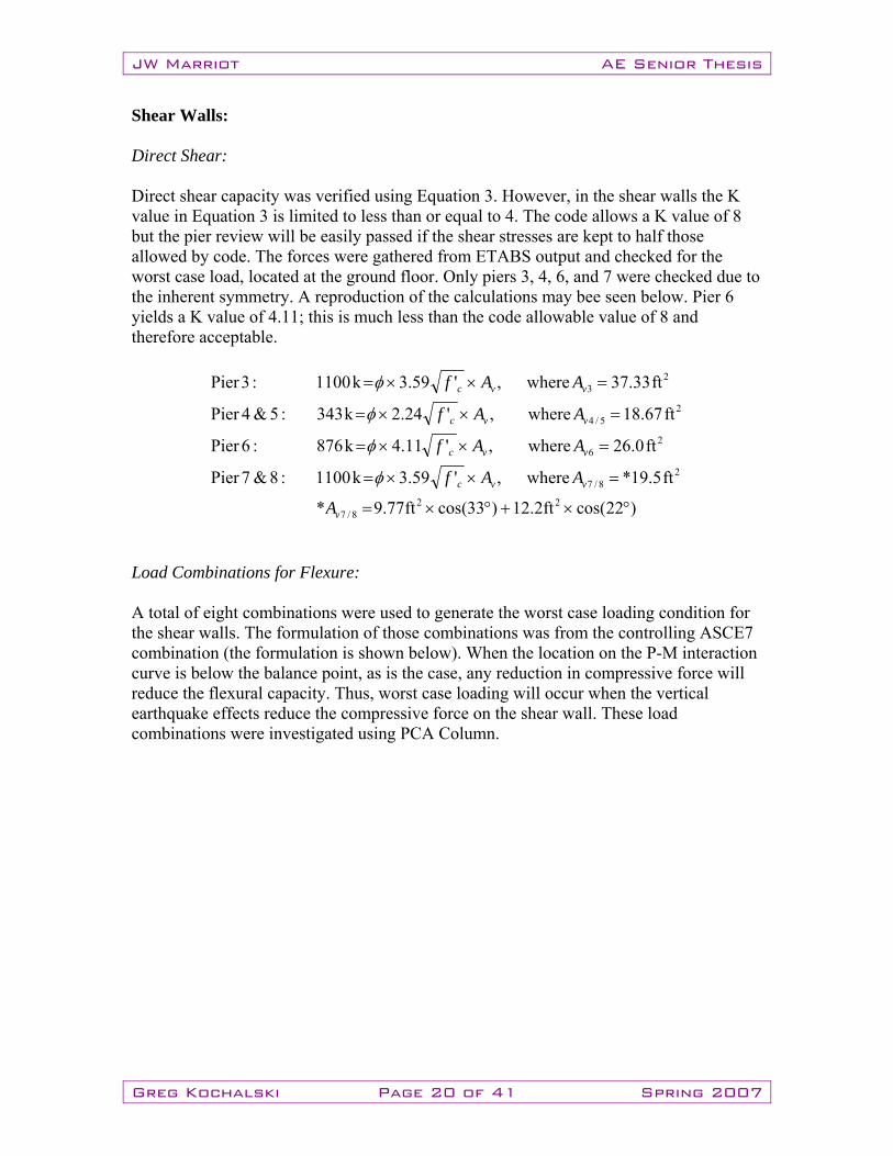
Shear Walls: Direct Shear: Direct shear capacity was verified using Equation 3. However, in the shear walls the K value in Equation 3 is limited to less than or equal to 4. The code allows a K value of 8 but the pier review will be easily passed if the shear stresses are kept to half those allowed by code. The forces were gathered from ETABS output and checked for the worst case load, located at the ground floor. Only piers 3, 4, 6, and 7 were checked due to the inherent symmetry. A reproduction of the calculations may bee seen below. Pier 6 yields a K value of 4.11; this is much less than the code allowable value of 8 and therefore acceptable.
)22cos(ft2.12)33cos(ft77.9*
ft5.19*where,'59.3k1100:8&7Pier
ft0.26where,'11.4k876:6Pier
ft67.18where,'24.2k343:5&4Pier
ft33.37where,'59.3k1100:3Pier
228/7
28/7
26
25/4
23
°×+°×=
=××=
=××=
=××=
=××=
v
vvc
vvc
vvc
vvc
A
AAf
AAf
AAf
AAf
φ
φ
φ
φ
Load Combinations for Flexure: A total of eight combinations were used to generate the worst case loading condition for the shear walls. The formulation of those combinations was from the controlling ASCE7 combination (the formulation is shown below). When the location on the P-M interaction curve is below the balance point, as is the case, any reduction in compressive force will reduce the flexural capacity. Thus, worst case loading will occur when the vertical earthquake effects reduce the compressive force on the shear wall. These load combinations were investigated using PCA Column.
JW Marriot AE Senior Thesis
Greg Kochalski Page 21 of 41 Spring 2007
( )( )( )( )( )( )( )( )
GRAVITYWTSELF
yy
xx
yx
yx
yx
yx
yx
yx
yx
yx
DSDSv
v
PPD
MEME
EED
EEDEED
EED
EEDEED
EED
EED
LSDSEEELD
+=
==
−−
−+
+−
++
−−
+−
−+
++
===+±+
XinEarthquaketodueYinEarthquaketodueWhere
0.13.07.08
0.13.07.070.13.07.06
0.13.07.05
3.00.17.043.00.17.03
3.00.17.02
3.00.17.01:becomes then ASCE7
0 and , 0.97,2.0where0.10.15.09.0:ASCE7
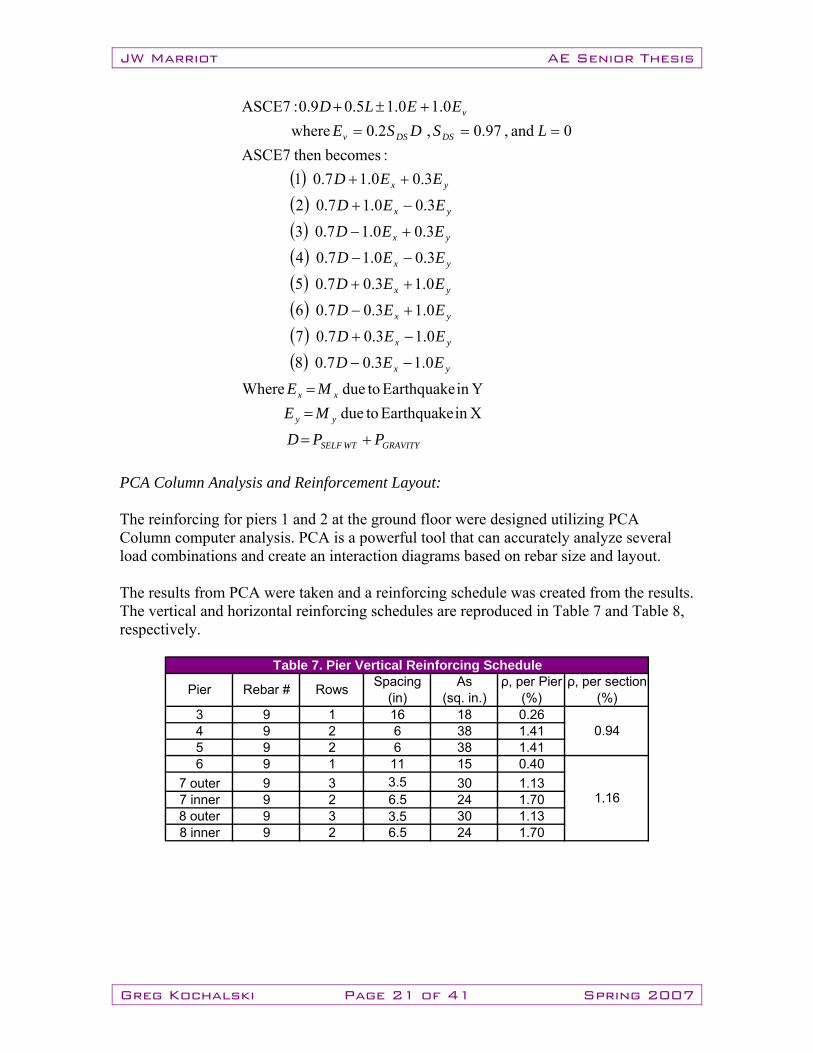
PCA Column Analysis and Reinforcement Layout: The reinforcing for piers 1 and 2 at the ground floor were designed utilizing PCA Column computer analysis. PCA is a powerful tool that can accurately analyze several load combinations and create an interaction diagrams based on rebar size and layout. The results from PCA were taken and a reinforcing schedule was created from the results. The vertical and horizontal reinforcing schedules are reproduced in Table 7 and Table 8, respectively.
3 9 1 16 18 0.264 9 2 6 38 1.415 9 2 6 38 1.416 9 1 11 15 0.40
7 outer 9 3 3.5 30 1.137 inner 9 2 6.5 24 1.708 outer 9 3 3.5 30 1.138 inner 9 2 6.5 24 1.70
Table 7. Pier Vertical Reinforcing Scheduleρ, per section
(%)As
(sq. in.)Rows
1.16
0.94
Pier Rebar # Spacing (in)
ρ, per Pier (%)
JW Marriot AE Senior Thesis
Greg Kochalski Page 22 of 41 Spring 2007
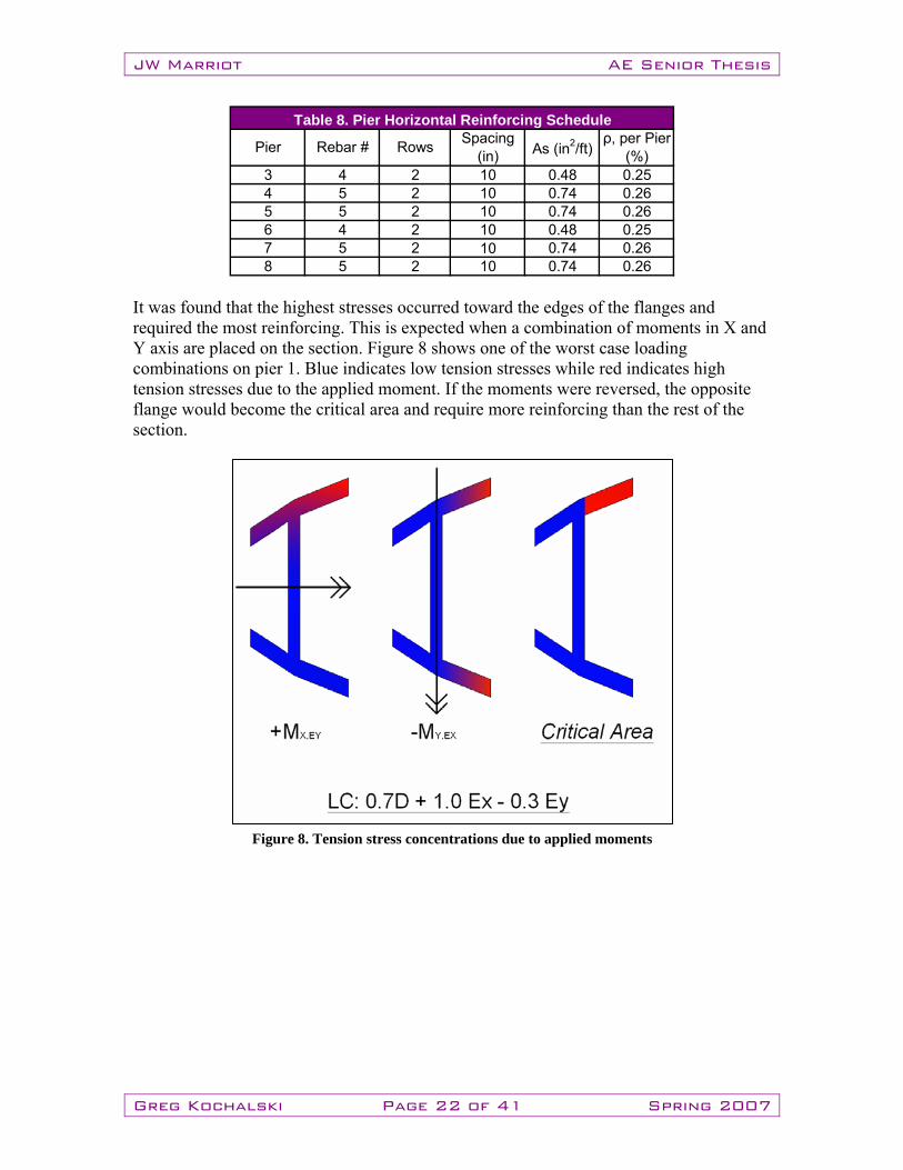
3 4 2 10 0.48 0.254 5 2 10 0.74 0.265 5 2 10 0.74 0.266 4 2 10 0.48 0.257 5 2 10 0.74 0.268 5 2 10 0.74 0.26
Table 8. Pier Horizontal Reinforcing Schedule
Pier Rebar # Rows Spacing (in) As (in2/ft)
ρ, per Pier (%)
It was found that the highest stresses occurred toward the edges of the flanges and required the most reinforcing. This is expected when a combination of moments in X and Y axis are placed on the section. Figure 8 shows one of the worst case loading combinations on pier 1. Blue indicates low tension stresses while red indicates high tension stresses due to the applied moment. If the moments were reversed, the opposite flange would become the critical area and require more reinforcing than the rest of the section.
Figure 8. Tension stress concentrations due to applied moments
JW Marriot AE Senior Thesis
Greg Kochalski Page 23 of 41 Spring 2007
Conclusion: The nonlinear response of the JWM matches the desired response. Plastic hinging occurs only in the coupling beams. They will act as the primary seismic force dissipation mechanism. The detailing of the designated nonlinear elements (coupling beams) provides sufficient ductility capacity. The beams will deform plastically and significantly depredate seismic forces. Shear walls have been designed for elastic response and will experience only flexural yielding. The walls maintain their lateral force resistance through large displacements and deform in a manner that distributes displacements evenly over the entire height. The peer reviewer will find the seismic performance of the JWM exceeds code-prescriptive design requirements. The inherent uncertainties of the assumptions to define seismic performance-deformation capacity, nonlinear demands, etc- are offset by the stern constraints under which the JWM was designed. The JWM surpasses an equivalent level of performance to the code and would smoothly pass peer review.

JW Marriot AE Senior Thesis
Greg Kochalski Page 24 of 41 Spring 2007
Depth: Post Tension Floor System
JW Marriot AE Senior Thesis
Greg Kochalski Page 25 of 41 Spring 2007
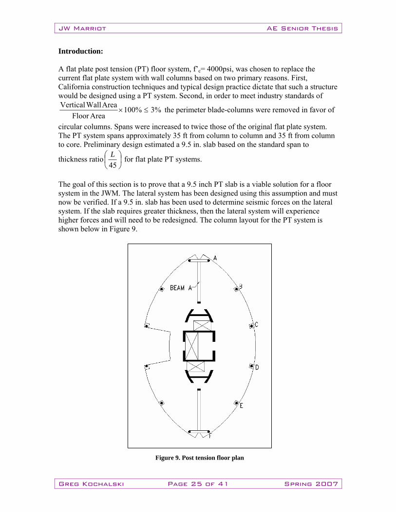
Introduction: A flat plate post tension (PT) floor system, f’c= 4000psi, was chosen to replace the current flat plate system with wall columns based on two primary reasons. First, California construction techniques and typical design practice dictate that such a structure would be designed using a PT system. Second, in order to meet industry standards of
%3%100AreaFloor
AreaWallVertical≤× the perimeter blade-columns were removed in favor of
circular columns. Spans were increased to twice those of the original flat plate system. The PT system spans approximately 35 ft from column to column and 35 ft from column to core. Preliminary design estimated a 9.5 in. slab based on the standard span to
thickness ratio ⎟⎠⎞
⎜⎝⎛
45L for flat plate PT systems.
The goal of this section is to prove that a 9.5 inch PT slab is a viable solution for a floor system in the JWM. The lateral system has been designed using this assumption and must now be verified. If a 9.5 in. slab has been used to determine seismic forces on the lateral system. If the slab requires greater thickness, then the lateral system will experience higher forces and will need to be redesigned. The column layout for the PT system is shown below in Figure 9.
Figure 9. Post tension floor plan
JW Marriot AE Senior Thesis
Greg Kochalski Page 26 of 41 Spring 2007
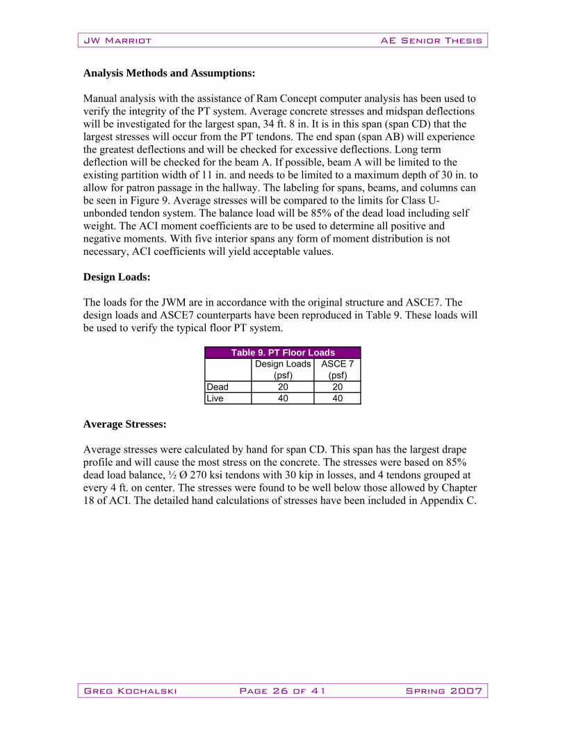
Analysis Methods and Assumptions: Manual analysis with the assistance of Ram Concept computer analysis has been used to verify the integrity of the PT system. Average concrete stresses and midspan deflections will be investigated for the largest span, 34 ft. 8 in. It is in this span (span CD) that the largest stresses will occur from the PT tendons. The end span (span AB) will experience the greatest deflections and will be checked for excessive deflections. Long term deflection will be checked for the beam A. If possible, beam A will be limited to the existing partition width of 11 in. and needs to be limited to a maximum depth of 30 in. to allow for patron passage in the hallway. The labeling for spans, beams, and columns can be seen in Figure 9. Average stresses will be compared to the limits for Class U- unbonded tendon system. The balance load will be 85% of the dead load including self weight. The ACI moment coefficients are to be used to determine all positive and negative moments. With five interior spans any form of moment distribution is not necessary, ACI coefficients will yield acceptable values. Design Loads: The loads for the JWM are in accordance with the original structure and ASCE7. The design loads and ASCE7 counterparts have been reproduced in Table 9. These loads will be used to verify the typical floor PT system.
Dead 20 20Live 40 40
Table 9. PT Floor LoadsDesign Loads
(psf)ASCE 7
(psf)
Average Stresses: Average stresses were calculated by hand for span CD. This span has the largest drape profile and will cause the most stress on the concrete. The stresses were based on 85% dead load balance, ½ Ø 270 ksi tendons with 30 kip in losses, and 4 tendons grouped at every 4 ft. on center. The stresses were found to be well below those allowed by Chapter 18 of ACI. The detailed hand calculations of stresses have been included in Appendix C.
JW Marriot AE Senior Thesis
Greg Kochalski Page 27 of 41 Spring 2007
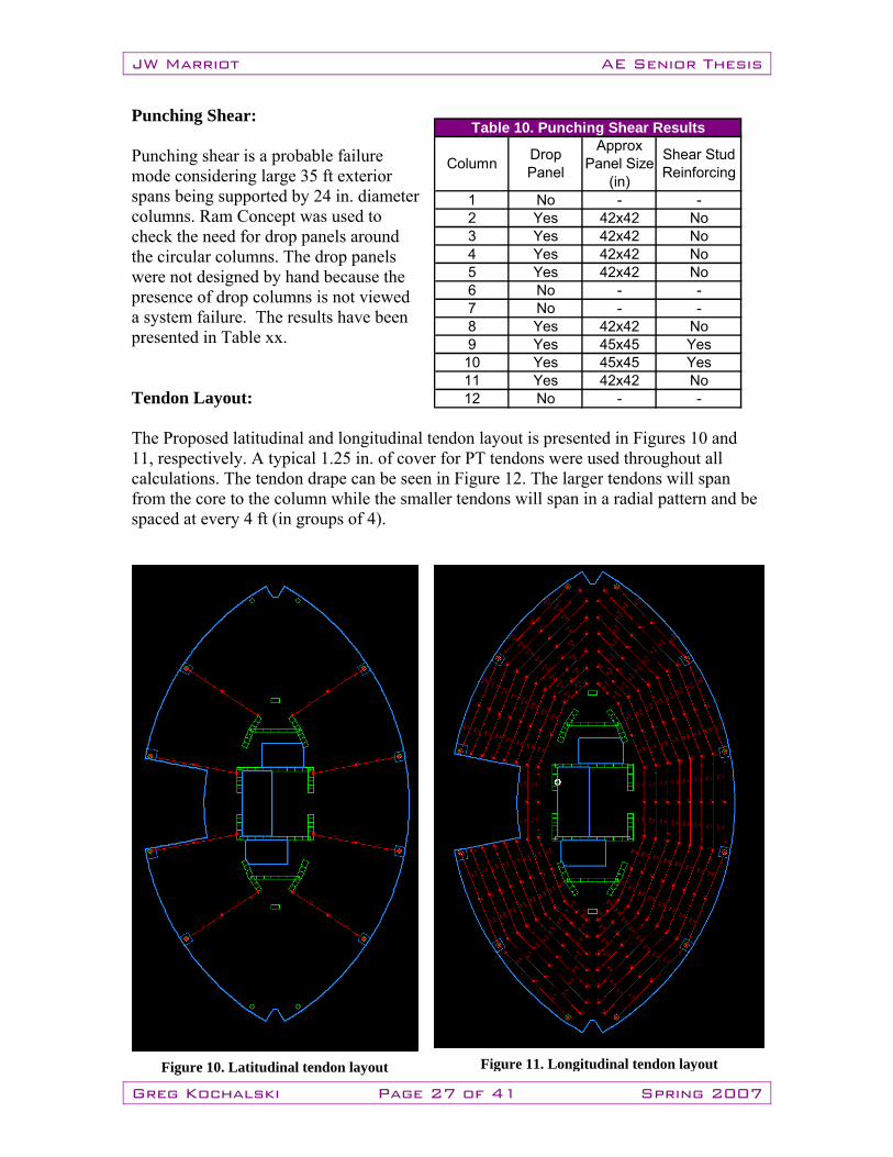
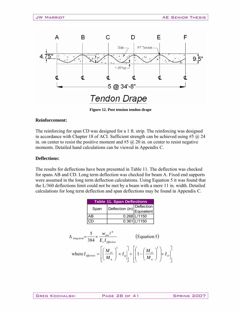
Punching Shear: Punching shear is a probable failure mode considering large 35 ft exterior spans being supported by 24 in. diameter columns. Ram Concept was used to check the need for drop panels around the circular columns. The drop panels were not designed by hand because the presence of drop columns is not viewed a system failure. The results have been presented in Table xx. Tendon Layout: The Proposed latitudinal and longitudinal tendon layout is presented in Figures 10 and 11, respectively. A typical 1.25 in. of cover for PT tendons were used throughout all calculations. The tendon drape can be seen in Figure 12. The larger tendons will span from the core to the column while the smaller tendons will span in a radial pattern and be spaced at every 4 ft (in groups of 4).
1 No - -2 Yes 42x42 No3 Yes 42x42 No4 Yes 42x42 No5 Yes 42x42 No6 No - -7 No - -8 Yes 42x42 No9 Yes 45x45 Yes10 Yes 45x45 Yes11 Yes 42x42 No12 No - -
Table 10. Punching Shear Results
Shear Stud Reinforcing Column Drop
Panel
Approx Panel Size
(in)
Figure 10. Latitudinal tendon layout Figure 11. Longitudinal tendon layout
JW Marriot AE Senior Thesis
Greg Kochalski Page 28 of 41 Spring 2007
Reinforcement: The reinforcing for span CD was designed for a 1 ft. strip. The reinforcing was designed in accordance with Chapter 18 of ACI. Sufficient strength can be achieved using #5 @ 24 in. on center to resist the positive moment and #5 @ 20 in. on center to resist negative moments. Detailed hand calculations can be viewed in Appendix C. Deflections: The results for deflections have been presented in Table 11. The deflection was checked for spans AB and CD. Long term deflection was checked for beam A. Fixed end supports were assumed in the long term deflection calculations. Using Equation 5 it was found that the L/360 deflections limit could not be met by a beam with a mere 11 in. width. Detailed calculations for long term deflection and span deflections may be found in Appendix C.
( )
⎥⎥⎦
⎤
⎢⎢⎣
⎡×⎟⎟
⎠
⎞
⎜⎜
⎝
⎛⎟⎟⎠
⎞⎜⎜⎝
⎛−+
⎥⎥⎦
⎤
⎢⎢⎣
⎡×⎟⎟
⎠
⎞⎜⎜⎝
⎛=
×=Δ
cra
crg
a
creffective
effectivec
sustermlong
IMM
IMM
I
IEw
33
4
1where
5Equation384
5 l
AB 0.268 L/1150CD 0.361 L/1150
Table 11. Span Deflections
Span Deflection (in) Deflection Equivalent
Figure 12. Post tension tendon drape
JW Marriot AE Senior Thesis
Greg Kochalski Page 29 of 41 Spring 2007
Conclusion: It is evident that a 9.5 in. PT slab is sufficient for the JWM redesign. The average stresses in the slab are well within acceptable the ACI required limits. The midspan deflections are satisfactory for a typical interior and exterior bay. However, the long term deflection requirement cannot be met with a beam limited to 11 in. wide. This is not an event that would determine the entire system a “failure”. There are two simple solutions to limit the deflection of beam A. First, a wider beam with multiple layers of reinforcement will increase the cracked moment of inertia and effective inertia. This adjustment would likely decrease the deflection to acceptable amounts. Second, an addition of a column at half span would decrease deflections and likely allow a beam that may fit within existing partitions. With these results in mind, it is likely that a thinner slab could be used if a PT system was to become the floor system of choice. The stresses may be further reduced by the addition of edge beams if a thinner slab were desired. The assumed concrete strength of 4000 psi may also be increased to increase the allowable stress limits. The formulation of seismic forces based upon the assumed weight of a 9.5 in. PT slab has been proven accurate. A thinner, lighter slab would likely prove acceptable. Therefore the lateral forces used in design have been shown to be conservative.
JW Marriot AE Senior Thesis
Greg Kochalski Page 30 of 41 Spring 2007
Breadth Study: Architecture
JW Marriot AE Senior Thesis
Greg Kochalski Page 31 of 41 Spring 2007
Problem Statement and Summary: “To redesign public and typical floor plans to accommodate the new lateral system while maintaining similar spaces for employee, patron, and service uses. Special care should be used to maintain the atrium as a strong architectural focal point.” Changing the elevator core to resist larger seismic forces present in Monterey will have significant effects on the floor plan’s inner core area. Electrical runs, mechanical runs, housekeeping spaces, vending machines, offices, and restrooms make use of the space that the new core will disrupt. Stairwells, fire exits, and fire protected areas present a particular problem that will need addressing. The architect has chosen to make the full height open air atrium a larger focal point of the structure. Currently, passengers exit the elevators on guest floors and immediately view the atrium and the Grand River. The atrium could have easily been designed as additional guest quarters but at large financial cost the current design was chosen. Such an emphasis by the architect and owner needs to be maintained. An elevator system must be created that matches handling capacity, average interval time, and elevator speed of the original design.
JW Marriot AE Senior Thesis
Greg Kochalski Page 32 of 41 Spring 2007
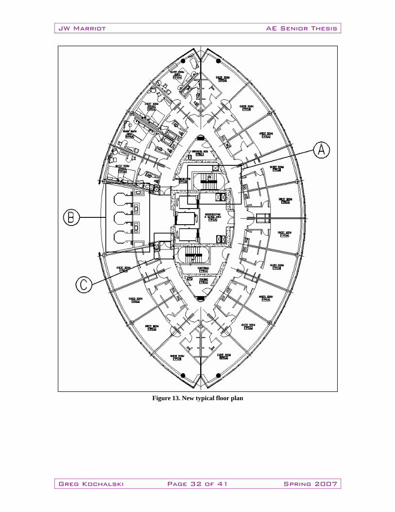
Figure 13. New typical floor plan
JW Marriot AE Senior Thesis
Greg Kochalski Page 33 of 41 Spring 2007
Solution: Fire Protection: In order to maintain proper fire protection a reconfiguration of stairwells and some corridors was necessary. The stairwells have been moved to their new location, highlighted in section A of Figure 13. The new location meets travel distance requirements without significantly affecting the architecture on public and typical floors. It should be noted that the northern stairwell exits on the second floor and transfers through a fire protected hallway (horizontal exit) to the larger multiuse fire exit. In order to keep the horizontal exit fire rated the bathroom entrances had to be changed to meet the following horizontal exit requirement per IBC: 1019.1: “exit enclosure shall not be used for other than egress…”
1019.1.2: “no penetrations shall be allowed except those related to exit egress or systems directly related to the function of the exit way…”
Now a vestibule will be used to enter those bathrooms to meet IBC requirements. The second floor plan can be seen in Appendix D. Two pairs of magnetic release fire doors, located on opposite sides of guest elevators, have been moved in order to maintain a fire protected space for the elevator area (section C of Figure 13). The entire area is now considered a fire protected zone and allows the use of glass doors for elevator entrances instead of metal rated doors. This is an important architectural decision that allows patrons to look outward through the atrium while waiting for elevators much in the same way as was intended in the original design. Elevator System: The Marriott Corporation has various design standards for elevatoring its hotels with the JW series being the best the brand has to offer. Marriott has minimum design requirements of 1 elevator per 100 rooms. Its specified 12% handling capacity is based on 1.75 persons per room. The average interval should be near 42.5 seconds and typically run at a speed of 500 fpm. In order to maintain the focus on the atrium it was necessary to remove the passenger elevators from the center of the lateral system. Three observation elevators will be relocated to line the atrium with three larger elevators (1 guest, 2 service elevators) remaining in the core’s center. The views created by observation elevators will maintain the architect’s vision for a strong atrium presence. The counterweights will be concealed within decorative columns between the glass elevator entrances to create ample space for three elevators side by side (section B of Figure 13). The new elevator design will make the group more compact and centrally located. This benefit will remove any chance forcing passengers to sprint to end cars upon arrival. In addition this makes the group more efficient for ADA accessibility requirements. The End cars will not need to be held as long for the possibility of a mobility impaired person entering at any given floor. These advantages will improve performance somewhere on
JW Marriot AE Senior Thesis
Greg Kochalski Page 34 of 41 Spring 2007
the order of 1-2 seconds. This becomes a significant advantage when the system is compounded over the 23 floors above ground level. An alternative to concealing the counterweights may be offered by using a proprietary system just released by Kone Elevator Co. The new “Maxi-Space” product does not require the use of a counterweight at all. The product is currently available at speeds up to 1000 fpm in Europe. Kone’s new system is presently being sales released in North America and will face numerous code approvals but will ultimately become approved for use. This system would remove the need for the decorative columns to conceal counterweights and add space in the lobby/lounge area. A Marriott standard approved handling capacity, interval time, and speed can be provided by either conventional counterweight or Kone systems. Miscellaneous Interior Spaces: On the ground floor, the new plans will most notably affect the lounge, front offices, and restrooms. The beginning of the atrium line has been moved back to allow for restaurant through traffic and patron build up on the first floor. The lounge area will be extended southward to compensate for area taken by the new elevator group. Equivalent overall lounge area and patron views are preserved. Two of the front office desks will now be located within the core adjacent to the front desk. The same number of desks has been kept. A significant advantage of the new design can be seen in the new restroom layout in the northern most core system quadrant. Before, a guest may have to walk from the restaurant to 90 ft past the front desk to reach accommodation if the single person restaurant bath is occupied. With an additional toilet in each bathroom the bar and restaurant can be better accommodated. The bathroom location and its entrance, just within the restaurant, will not disrupt dining patrons as the old location may have. On typical floors there will be ample space for vertical electrical runs, mechanical ducts, and housekeeping quarters. Vending and ice machines will be repositioned in the two smaller spaces at the north and south poles of the lateral system. Removal of Wall Columns: One of the advantages of the new post tension floor system is the removal of the wall columns along the perimeter of the JWM. The use of circular columns instead and greater spans will give the architect several benefits. The floor plan may be designed with greater freedom without a column every 17 ft along the perimeter. Each room will gain floor area from the reduction of partitions thickness. Previously partitions between guest rooms were 16 inches thick in order to house wall columns, now partitions may be reduced to 8 inches thick. Each room will include a small obstruction cause by thicker columns. However the reduction of partition thickness will offset any loss due to the circular columns.
JW Marriot AE Senior Thesis
Greg Kochalski Page 35 of 41 Spring 2007
Conclusion: The new lateral force resisting system will disrupt much of the architecture. However, a viable solution has been presented that creates several advantages. The new elevator group will meet the rigorous Marriott standards. Observation elevators with glass doors will preserve the architect’s vision for a dramatic full height atrium. The buildings fire stairwells and corridors have been adjusted to meet IBC requirements at minimal costs. All service spaces have been relocated with similar area allocations. The architect will have greater freedom to design spaces with the removal of wall columns and addition of greater spans between columns. The new floor plans will serve guests and employees in a manner befitting a JW Marriott.
JW Marriot AE Senior Thesis
Greg Kochalski Page 36 of 41 Spring 2007
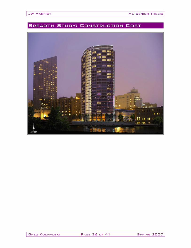
Breadth Study: Construction Cost
JW Marriot AE Senior Thesis
Greg Kochalski Page 37 of 41 Spring 2007
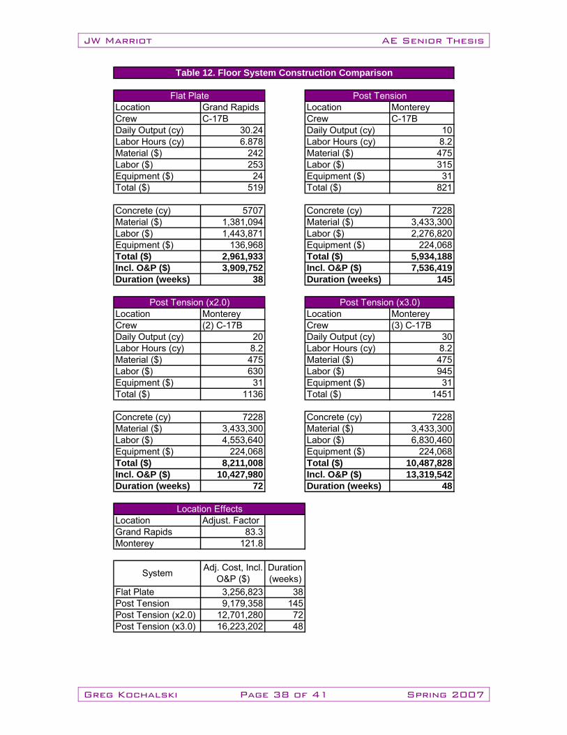
Problem Statement and Summary: “To investigate the effects of the new post tension system on the price and duration of construction and compare the results to the existing flat plate system.” Inherent schedule, constructability, and cost effects will accompany any change in floor systems to the JWM. Post tension floor systems are more skill intensive than are flat plate systems and therefore will lead to larger overall costs by slowing the schedule and pricier labor. In addition to the change in floor systems the JWM will suffer negative location effects resulting from the relocation to Monterey, CA from Grand Rapids, MI. Secondary cost effects of the post tension system change will be felt by the project coordination process. Other trades, for instance MEP, will need to be brought on the project earlier to determine slab openings for ducts/pipes. Because of the possibility of severing a stressed tendon cutting the slab after tendons have been stressed is dangerous and typically avoided. Only after slab openings are known can a final tendon layout be established by the structural engineer. These longer coordination times will result in increased consultant fees. Comparison: RS Means 2007 was used to gather the construction data presented below in Table 12. A complete list of assumptions is available within the hand calculations presented in Appendix B. Conclusion: The actual construction schedule totals 47 weeks from the beginning of the ground floor to the completion of the roof level. The data found by RS Means cannot account for the unique circumstances of the JWM. With an average annual snow fall of 64 inches in Grand Rapids, winter weather effects demanded an allowance in the schedule. The odd shape and winter weather can be held accountable for the projected 9 week discrepancy. Due to the lower daily production, cost of labor, and deeper slab thickness the new post tension system will significantly increase the price of the structural system. The existing flat plate uses a 7.5 in. slab while the post tension system uses a 9.5 in. slab. This change in thickness results in an addition of over 1500 cubic yards of concrete to the structure. Finally, any delay in floor system completion will affect the critical path. This delay will produce staggering secondary effects in the form of capital interest losses. If the owner wished to avoid secondary affects by matching the existing schedule labor costs would increase 3 fold. Based on cost and schedule affects, it is unlikely that the owner would choose to use a post tension system designed in accordance with this thesis.
JW Marriot AE Senior Thesis
Greg Kochalski Page 38 of 41 Spring 2007
Location Grand Rapids Location MontereyCrew C-17B Crew C-17BDaily Output (cy) 30.24 Daily Output (cy) 10Labor Hours (cy) 6.878 Labor Hours (cy) 8.2Material ($) 242 Material ($) 475Labor ($) 253 Labor ($) 315Equipment ($) 24 Equipment ($) 31Total ($) 519 Total ($) 821
Concrete (cy) 5707 Concrete (cy) 7228Material ($) 1,381,094 Material ($) 3,433,300Labor ($) 1,443,871 Labor ($) 2,276,820Equipment ($) 136,968 Equipment ($) 224,068Total ($) 2,961,933 Total ($) 5,934,188Incl. O&P ($) 3,909,752 Incl. O&P ($) 7,536,419Duration (weeks) 38 Duration (weeks) 145
Location Monterey Location MontereyCrew (2) C-17B Crew (3) C-17BDaily Output (cy) 20 Daily Output (cy) 30Labor Hours (cy) 8.2 Labor Hours (cy) 8.2Material ($) 475 Material ($) 475Labor ($) 630 Labor ($) 945Equipment ($) 31 Equipment ($) 31Total ($) 1136 Total ($) 1451
Concrete (cy) 7228 Concrete (cy) 7228Material ($) 3,433,300 Material ($) 3,433,300Labor ($) 4,553,640 Labor ($) 6,830,460Equipment ($) 224,068 Equipment ($) 224,068Total ($) 8,211,008 Total ($) 10,487,828Incl. O&P ($) 10,427,980 Incl. O&P ($) 13,319,542Duration (weeks) 72 Duration (weeks) 48
Location Adjust. FactorGrand Rapids 83.3Monterey 121.8
Flat Plate 3,256,823 38Post Tension 9,179,358 145Post Tension (x2.0) 12,701,280 72Post Tension (x3.0) 16,223,202 48
Post Tension
Post Tension (x2.0) Post Tension (x3.0)
Flat Plate
Table 12. Floor System Construction Comparison
Adj. Cost, Incl. O&P ($)System Duration
(weeks)
Location Effects

JW Marriot AE Senior Thesis
Greg Kochalski Page 39 of 41 Spring 2007
Conclusions and Recommendations
JW Marriot AE Senior Thesis
Greg Kochalski Page 40 of 41 Spring 2007
Conclusion: After redesigning the JW Marriott for Monterey, CA it was evident significant structural, cost, and architectural changes accompany the relocation. The building was subjected to higher seismic loads and required a new lateral system. The new lateral system affected the choice of floor system, construction cost and duration, and interior architecture. The lateral system achieved the desired nonlinear response. With plastic hinges located in the beams and flexural yielding in the walls, the system maintains its lateral force resistance through large displacements and deforms evenly over the entire height. The stringent standards imposed in the design process make certain the lateral system surpasses code required performance and would easily pass the required peer review. The assumed thickness of the post tension slab was investigated and determined to be adequate. The lateral forces that were based on the assumed thickness and column layout have been proven correct. Code requirements approved of the average stresses and deflections present in the slab. The construction costs and duration were significantly increased due to the higher skilled and timelier labor necessary to construct a post tension system. The direct capital losses are significant when compared to the cost and expeditiousness of the original flat plate system. The new, longer duration will cause secondary capital losses by delaying hotel occupancy and diminishing the interest from hotel revenues. The architecture saw the greatest change in the atrium space. Elevators were moved out of the core in order to maintain a focus on the signature atrium. The new system uses observation elevators to match the architect’s vision. Fire corridors, stairwells, and other interior spaces were rearranged to match original specifications with minimal aesthetic losses. The lateral system created several benefits, most notably the addition of restaurant bathrooms and reduced elevator interval times. Recommendations: Although the post tension system is a viable alternative to the original system, the change would raise construction costs significantly. In light of this, it is unlikely that the owner would choose a post tension floor system in place of the original system. Despite industry vertical wall area standards, it is more economical to use the original floor system with the new core. The original floor system should be used in the Monterey design. The thinner original flat plate system would decrease the seismic forces on the structure considerably. The lateral system should be redesigned for these smaller forces. A smaller, thinner system may be sufficient to resist the lower forces. The reduction of shear wall size would reduce the vertical area closer to industry standards. The new lateral system design provides sufficient ductility and deformation capability essential to withstand Monterey seismic forces. Only size, not characteristics should be modified for lower seismic forces.

JW Marriot AE Senior Thesis
Greg Kochalski Page 41 of 41 Spring 2007
Acknowledgements: I would like to thank many people for making my senior thesis experience possible. First and foremost I would like to thank my parents for making a higher education a reality. In addition I am grateful to the AE faculty for countless hours of assistance and my brother for his help to procure the drawings and his guidance. Last I would like to thank my friends for making my AE experience unforgettable.