exercise 9 „creating your hil test bench with simulink”
TRANSCRIPT

Exercise 9 „Creating your HiL test bench with Simulink”
Attention: For this exercise you need a Windows Operating System and MATLAB Simulink 2017b.
In this exercise, it is your task to develop a "Hardware in the Loop" test bench. For this you will use a
Raspberry Pi model 3B and an Arduino Due. The Raspberry is used to simulate the car ride in
realtime. On the Raspberry runs the model known from the previous exercises, but without the
gearbox functionality. We would like to outsource this to external hardware, more specifically to the
Arduino.
The simulated car transfers relevant data (current speed and brake signal) to the gearshift in real
time. The gearbox (Arduino) reacts to the transferred values and calculates the current gear and the
clutch signal and transfers them to the Raspberry so that it can work with the new values.
In general, a HiL simulation can be described as shown in Figure 0-1.
Figure 0-1 HiL in general
Consider Figure 0-1 to think about how the specific model of this exercise could look like.

After modelling what your HiL test bench looks like ask yourself why it makes sense to simulate a car
and test out individual car components from the simulation. Wouldn’t it make more sense to test the
gear shift in a real car? Justify your answer.
The structure of the HiL testbench and its importance in practice should be clearer now. In the
following, it will be your task to implement some essential parts that are important for the exchange
of data between the model and the extern hardware. You should also try to integrate your own
Gearbox function in the partially given HiL system.
Connected to your working PC you will find a Raspberry Pi and an Arduino Due. Before starting the development, type in the following line to check whether the Raspberry Pi is correctly linked with the Computer: h = raspberrypi
In case the connection is working you will see following lines as result. If you receive any error code,
please refer to your supervisor.
h =
raspberrypi with properties:
DeviceAddress: '169.254.0.2'
Port: 22
If an error message occurs, use the following command:
mypi = raspi ('IP address', 'hostname', 'password')
Now an IO server is set up on the Raspberry Pi, which allows you to access the interfaces on the Pi.
Make sure that as highlighted Figure 0-2, the correct Raspberry model is displayed. If you still cannot
establish a connection, please ask for help.
Figure 0-2

Starting the development:
Before you can start, please read the description of the individual components carefully. Only then
you will be able to implement the missing sections in a meaningful way. Before you start please
download the corresponding models form the Website.
Attention:
In order to design the HiL test bench, you should definitely have performed “Lab Exercice 6”.
The Gearbox Controller on the Arduino:
You will start to design and partially test the software for the Arduino Due. Please open the
"Gearbox_Controller.slx" model.
You can see that the model is not completed yet. Already available are:
1. The serial interface. This is responsible for the data exchange with the Raspberry Pi.
2. The brake signal which is read by the Arduino. Pin 52 indicates that the signal is being read
out through the Arduino on this pin. This is important for the future when wiring Arduino and
Raspberry.
3. The control-signals Clutch, Gear_0, Gear_1 and Gear_2 are also present (write mode). Again,
it is already given which pins to use.
4. A trigger that should be used to execute a subsystem at given intervals.
After discussing the existing components, you will complete the "Gearbox_Controller.slx" model step
by step.

Checking the digital outputs:
You will first test if the Arduino's digital outputs are working properly. To do this, build up the
following circuit.
Figure 0-3
Once constructed, create a constant for each pin in the "Gearbox_Controller.slx" model and connect
it to the Arduino function. If the constant is greater than zero, the LED should be turned on. If the
value of the constant is zero, the LED will be turned off.
Once you have prepared your model as described, you have to transfer it to the Arduino. To do this,
choose the following settings.
First set the "Running Mode" to External and then open the “Model configuration parameters” as
shown in the next Figure.
Figure 0-4
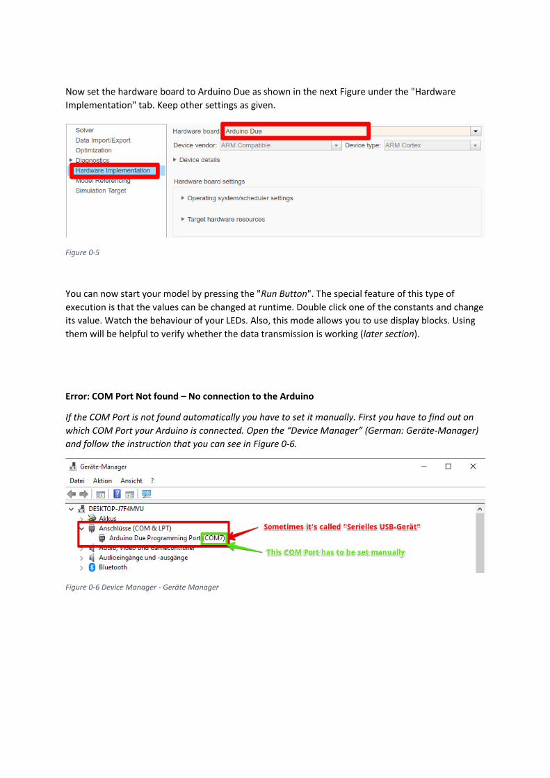
Now set the hardware board to Arduino Due as shown in the next Figure under the "Hardware
Implementation" tab. Keep other settings as given.
Figure 0-5
You can now start your model by pressing the "Run Button". The special feature of this type of
execution is that the values can be changed at runtime. Double click one of the constants and change
its value. Watch the behaviour of your LEDs. Also, this mode allows you to use display blocks. Using
them will be helpful to verify whether the data transmission is working (later section).
Error: COM Port Not found – No connection to the Arduino
If the COM Port is not found automatically you have to set it manually. First you have to find out on
which COM Port your Arduino is connected. Open the “Device Manager” (German: Geräte-Manager)
and follow the instruction that you can see in Figure 0-6.
Figure 0-6 Device Manager - Geräte Manager

To set the COM manually open the “Model Configuration Settings” and set the settings like in
Figure 0-7 Set COM manually
Building the Serial Communication
In the next section you will create a simple transfer of data between Raspberry Pi and Arduino.
Open the model "raspberry_easy_transmission.slx". In this model, there is only one block whose task
is to send data via the serial interface. Please do not change anything at its settings, everything is
already set up.
Since the Arduino expects only one value (v[m/s]) you have to create one constant and initialize it
with a realistic value (think about what the maximum speed could be). Also, it’s your duty to change
the datatype of the constant to int8.
If you have worked out a solution, various settings must be made before transferring the code to the
Raspberry. Set Run Mode to External and open the “Configuration Parameters” menu. As shown in
Figure 0-8, go to the Hardware Implementation Tab. Select the Raspberry Pi as hardware board and
make sure the username, password and IP address are set correctly.
Figure 0-8

In order to test the transfer, you also have to make some changes on the Arduinos side. Open the
"Gearbox_Controller.slx" model again parallel to the "raspberry_easy_transmission.slx" model.
This time you will implement the code around the "Serial Receive" block. Connect the data output of
this block to a display block to check the received values in external mode.
The nature of the data transmission can result in another serious problem. We use a serial interface
to be more specific the UART (Universal Asynchronous Receiver Transmitte) protocol. The name of
this protocol already indicates that it is an asynchronous type of data transmission. This can result in
that one of the two communication parties is working faster than the other. This results in two
possible scenarios:
1. The transmitter is faster than the receiver:
The receiver is not able to pick up the data as fast as it gets it. This results in data loss. This
can be tolerated if the application does not require every single data value to fulfil its
function.
2. The receiver is faster than the transmitter:
The receiver reads data from its data register much faster than it gets new data there. If the
data register is read out, this is then set to the value zero. The result is that erroneous zeros
are read out. These erroneous zeros are catastrophic for subsequent calculations and
therefore they must be intercepted.
In the test bench you designed, the receiver will read data faster than it receives it. Therefore, it is
your job to design a corresponding algorithm that removes the bad zeros and instead passes the last
valid value to the display.
Tip:
Access the "Switch" and the "Delay" block.
Or even better use the Status output of your receiver block. Therefore, read the help section of this
element.

Once you have implemented this functionality, you must interconnect the Arduino and Raspberry as
shown in the next Figure.
Figure 0-9
Connect both the raspberry and the Arduino to your computer.
Attention:
Now first start the "Gearbox_Controller.slx" model, if this is started you can also press the "Run
Button" on the "raspberry_easy_transmission.slx" model.
Possible Error:
If you receive an error message like in Figure 0-10 make sure, that your OS on the Pi fits the
“BoardName” - the “BoardName” equals your Raspberry Pi Model - which you can see in Figure 0-2.
This exercise should be performed with the Raspberry Pi Model 3B.
Figure 0-10

If you've done everything right, you should see the value you wrote in the constant on the
“raspberry_easy_transmission.slx” model in the display blocks on the “Gearbox_Controller.slx
model”. You can change the constant in "raspberry_easy_transmission.slx" at runtime, then you
should be able to see the new value on the Arduino model.
Error “No values are displayed and the simulation time on my Arduino model is frozen”
This can happen because the external mode needs a lot of resources and then as result the model will
freeze until you stop the transmission of data by the Raspberry.
To test your software with another option open the model “Arduino_receive_LED”. In this model you
will turn a LED on or off, with the help off a “switch” block which is already given.
To verify the behaviour, you use to compare values (20 and 70).
Please wire your Arduino with the LEDs like in the figure below.
Figure 0-11
Transfer your model to the Arduino by clicking the button you can see in the below figure.
After that start your "raspberry_easy_transmission.slx" in external mode so that it’s possible to
change the constants’ value.

Finishing the Gearbox:
Now you will take the last steps. First you will finish the "Gearbox_Controller.slx" model. To do this,
design an algorithm that will give you the gear in dependence of the speed v[m/s]. Use a triggered
subsystem connected to the given trigger. You can now deploy your model to the Arduino.
Building the simulation on the Raspberry Pi:
Now open the model "Virtual_Race.slx". This model is very extensive. To understand how the
subsystems are working, read the description below. Most of these systems should be known from
the previous exercises. This model will be transferred to the Raspberry Pi and is simulating the car to
test your Gearbox.
Car_Model
This subsystem has the same functionality as the “Car_Physics” model known from exercise 3.
The acceleration „a[m/s^2]“, the current speed „v[m/s]“ and the driven distance “s[m]” are
calculated with the engine power “P[W]”, the gear “Gear[1..6]” and the motor speed “n_M[1/min]”.
Engine
This block simulates the car’s engine like in exercise 4.
Clutch
In this subsystem the clutch is simulated. If the input “Clutch” has the value “1” then “P_in[W]”
equals “P_out[W]”. If the “Clutch” has the value “0” then “P_out[W]” equals zero.
Gear Box
With the current speed “v[m/s]” this subsystem calculates the speed of the wheels “n_W[1/min]”
and the engine speed “n_M[1/min]” is determined by the gear.
Michael – Intelligent Driver
This subsystem is quite similar to the “Intelligent Driver” known from exercise 6. It detects the
current position on the track and keeps the maximum allowed speed by braking and accelerating.
Beyond the known model, this system calculates the number of laps driven.
Input Conditioning

This subsystem is converting the datatype of its input to int8 values. This is necessary because the
model running on the Arduino doesn’t need a high precision to educate a good result. If you use the
datatype double your memory usage on the hardware will increase drastically. So, it’s good practise
to always use the smallest datatype which still fits the requirements.
Output Conditioning
This Subsystem converts the binary result of the gear to a decimal value again.
Stop Watch
This subsystem determines the current lap time by using the current “Lap” and the current
simulation time “t[s]”. This system also calculates which lap was the fastest and returns its index and
time.
Start signal
In this section, a signal is sent from the user interface after pressing the "Start Race" button. This
signal starts the Simulink model on the Raspberry Pi.
Data for PC
In this section, the data calculated on the Raspberry Pi is collected and sent via UDP to the computer
for visualization.
Receive data from Arduino
In this section, the Raspberry Pi reads the control signals sent by the Arduino.
Send Data to Arduino
In this subsystem the speed v[m/s] and "Brake" are transmitted to the Arduino.

Wire your Hardware Board like in the following table (in Figure 0-12 you can see the Pin Layout for
the Raspberry Pi):
Functionality Raspberry Arduino
Gear_0 GPIO 16 (read) Pin 22 (write)
Gear_1 GPIO 20 (read) Pin 24 (write)
Gear_2 GPIO 21 (read) Pin 26 (write)
Clutch GPIO 26 (read) Pin 28 (write)
Brake GPIO 17 (write) Pin 52 (read)
Transmit (TX) GPIO 14 (write) -----------
Receive (RX) ----------- RX1 (read)
GND GND GND
Figure 0-12

Now open the "Configuration Parameters" menu of the "Virtual_Race.slx" model and make sure that
under "Hardware Implementation" the Raspberry Pi is selected as hardware board. Also, make sure
that the username, password and IP address are set correctly.
Then click on the button shown in Figure 0-13. The code will be transferred to the Raspberry Pi now.
Figure 0-13
User Interface
Now open the model "GUI_Virtual_Race.slx". In this model you will see a user interface that
visualizes the data that the Raspberry Pi has calculated and sent to the computer. Click on the
Subsystem tab like in Figure 0-14.
Figure 0-14
Before starting the application, make sure that the block shown in Figure 0-15 (you will find this in
the Subsystem of "GUI_Virtual_Race.slx") is active and not greyed out. This block has the task to
force the simulation speed of the GUI to real time.
Figure 0-15
Now click on the Run button. The model should start, and you can see that the simulation time runs
much slower than in the previous exercises that took place on the computer.
Next, click on the Start Engine button (hold it for 1-2 seconds). Afterwards the RPM pointer should
increase to the value 1000 (engine speed).
Now click on the "Start Race" button (hold it for 1-2 seconds). The LEDs above the buttons should
flash green one after the other. When all three LEDs are green, the "VirtualRace" model will start on
the Raspberry Pi and the ride will begin.
At the top of the GUI you can see where you are on the course. Green sections have to be
interpreted as a straight line and yellow sections as a curve. Also visualized are the current speed, the
fastest lap time, the fastest lap index, the current lap time, and the current lap index.
Have fun racing and congratulations for the design of your first HiL application!