experiment of torsionally-coupled rc …peer.berkeley.edu/events/2009/icaese3/cd/files/pdf/tseng...1...
TRANSCRIPT
1
EXPERIMENT OF TORSIONALLY-COUPLED RC BUILDING SUBJECTED TO BI-DIRECTIONAL CYCLIC LOADING
Chien-Chuang Tseng1, Shyh-Jiann Hwang2, Y.L. Mo3, Yeong-Kae Yeh4, and Yi-Tsung Lee5
ABSTRACT
Tests on a 2-story RC building subjected to bi-directional reversed cyclic loading have been performed to examine the torsional effect caused by the eccentricity at the National Center for Research on Earthquake Engineering (NCREE) in Taiwan. This is an internationally-cooperated project between NCREE and the University of Houston (UH). In order to evaluate torsional effect, we designed two low-rise shear walls at the east side and one mid-rise shear wall at the north side of the building to make it unsymmetrical. For the purpose of this experiment, loading history must satisfy two conditions. First, to control the mass center on the 2nd floor the displacement ratio of long to short directions is 1:2. Second, the horizontal force ratio of story 2 to story 1 is 1.83 that is equal to the ratio of story height. This experiment used 10 sets of static hydraulic actuators, and the capacity is 981 kN for each actuator. We allocated 5 sets of actuators in the long direction, i.e. there were 2 sets on the 1st floor and 3 sets on the 2nd floor. Similarly, there were 2 sets on the 1st floor and 3 sets on the 2nd floor in the short direction. This research focused on the development and progression of nonlinear combined actions in the experimental technology. The results of this experiment will be used to correlate analytical tools and the new design methodologies.
.
INTRODUCTION
The objective of this integrated experiment is proposed to address the complex behavior of reinforced concrete buildings subjected to multi-directional earthquake loading and the subsequent interactions resulting from the nonlinear response of individual components that compound further the multi-directional affect of the ground motion. The entire effort is led by the National Center for Research on Earthquake Engineering (NCREE) in Taiwan and the University of Houston (UH). Emphasis is placed on using simulation response histories to provide actuation forces applied to the reinforced concrete buildings subjected to reversed cyclic loading. The associated simulated response will be fed back into building characteristics for additional shake table simulations. The results will be used to correlate analytical tools and the new design methodologies.
1 Associate Research Fellow, National Center for Research on Earthquake Engineering, [email protected]
2 Professor, Department of Civil Engineering, National Taiwan University
3 Professor, Department of Civil and Environmental Engineering, University of Houston, Houston, Texas, USA 4 Research Fellow, National Center for Research on Earthquake Engineering
5 Graduate Student, Department of Civil Engineering, National Taiwan University
2
EXPERIMENTAL PROGRAM
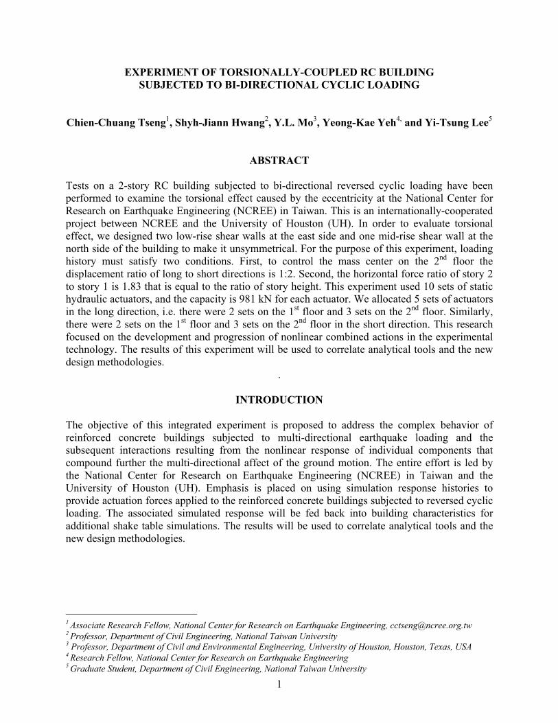
Test Specimen Fig. 1 shows that the specimen is two stories, the short direction is one bay, and the long direction is two bays. The net height of column on the 1st floor is 2000 mm, on the 2nd floor is 1500 mm. The cross section size of each column is 400 x 400 mm, and of each beam is 300 x 400 mm. In order to test the torsional effect, we designed the walls of the building to be unsymmetrical. We allocated two low-rise walls and a mid-rise wall at east and north sides, respectively, as shown in Fig. 2. The short span of east side at the long direction has disposed Wall A (Height/Width Ratio is 0.64) and Wall B (Height/Width Ratio is 0.48), and the north side of specimen has disposed Wall C (Height/Width Ratio is 1.5) at the short direction. Walls A and B are shear critical, while Wall C is both shear and flexure critical. Hence, the characteristics of various types of walls can be identified. C1-2F (column 1 on the 2nd floor) and C1-1F (column 1 on the 1st floor) are short (shear critical) and normal (flexure critical), respectively, that are subjected to biaxial loading and axial compression (0.2 cf ′ ); C2-2F (column 2 on the 2nd floor) and C2-1F (column 2 on the 1st floor) are short (shear critical) and normal (flexure critical), respectively, that are subjected to biaxial loading only. The structural behavior of columns with various conditions can also be examined by this arrangement.
Fig. 1. Sketch of RC building frame Fig. 2. Global photo of the test specimen
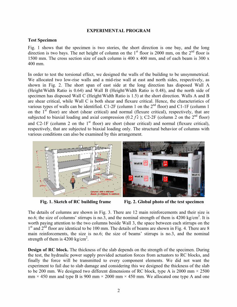
The details of columns are shown in Fig. 3. There are 12 main reinforcements and their size is no.6; the size of columns’ stirrups is no.3, and the nominal strength of them is 4200 kg/cm2. It is worth paying attention to the two columns beside Wall 3, the space between each stirrups on the 1st and 2nd floor are identical to be 100 mm. The details of beams are shown in Fig. 4. There are 8 main reinforcements, the size is no.6; the size of beams’ stirrups is no.3, and the nominal strength of them is 4200 kg/cm2. Design of RC block. The thickness of the slab depends on the strength of the specimen. During the test, the hydraulic power supply provided actuation forces from actuators to RC blocks, and finally the force will be transmitted to every component elements. We did not want the experiment to fail due to slab damage and considering this we designed the thickness of the slab to be 200 mm. We designed two different dimensions of RC block, type A is 2000 mm × 2500 mm × 450 mm and type B is 900 mm × 2000 mm × 450 mm. We allocated one type A and one
3
type B RC block on each floor. The sketch of RC block shows as Fig. 5. And the details of RC block shows as Fig. 6.
Fig. 3. The details of columns Fig. 4. The details of beams
Fig. 5. Sketch of RC block
4
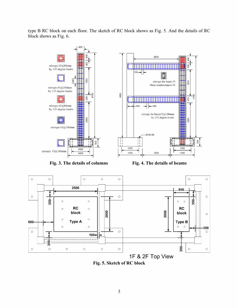
Fig. 6. The details of Type A and Type B RC block
To take consideration of RC block subjected to such shear force, we disposed shear reinforcement and preload bolts. Each preload bolt can provide 80 tonf tension, there are four sets on type A and eight sets on type B (shows as Fig. 7 and Fig. 8). In that case, we can avoid slip displacement between RC block and floor.
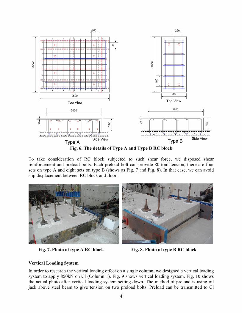
Fig. 7. Photo of type A RC block Fig. 8. Photo of type B RC block
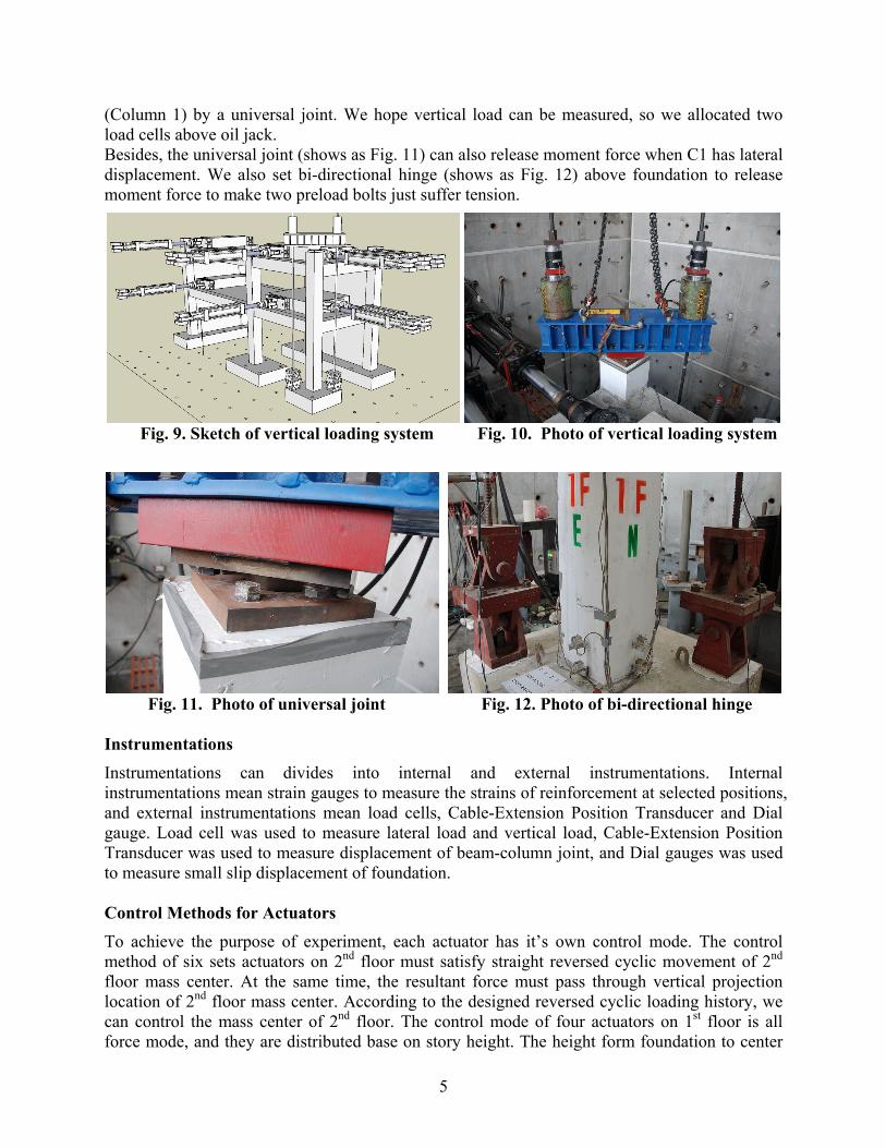
Vertical Loading System In order to research the vertical loading effect on a single column, we designed a vertical loading system to apply 850kN on Cl (Column 1). Fig. 9 shows vertical loading system. Fig. 10 shows the actual photo after vertical loading system setting down. The method of preload is using oil jack above steel beam to give tension on two preload bolts. Preload can be transmitted to Cl
5
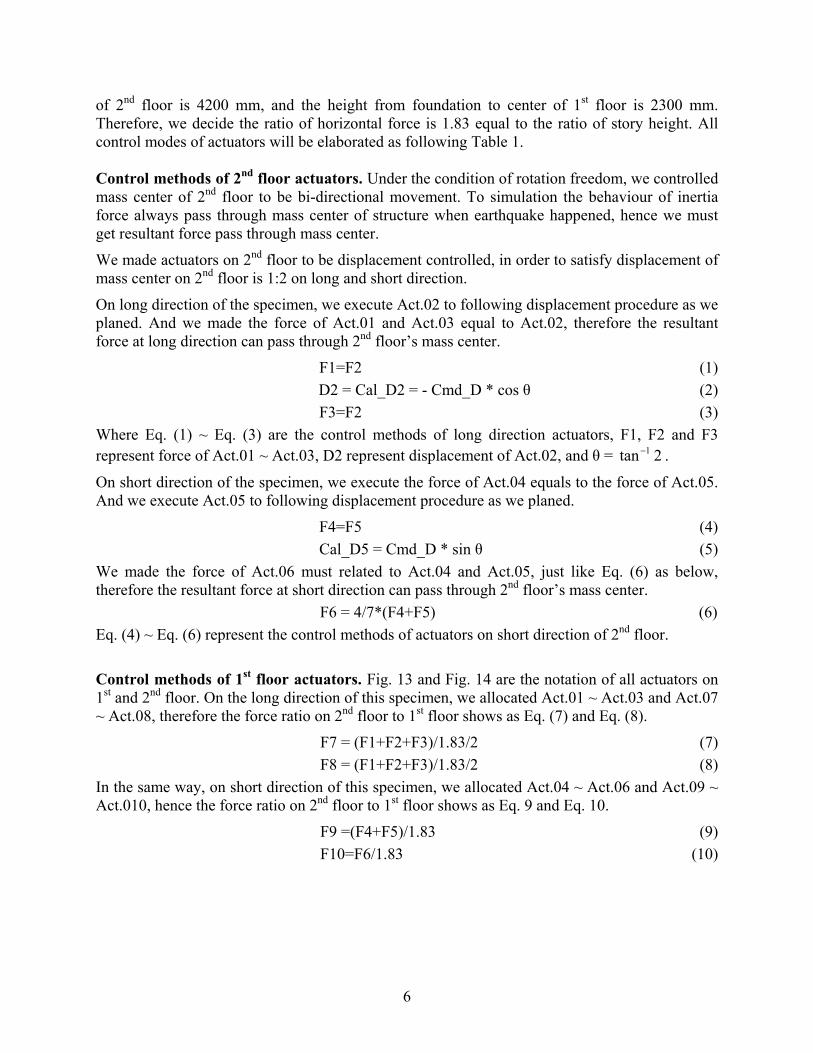
(Column 1) by a universal joint. We hope vertical load can be measured, so we allocated two load cells above oil jack. Besides, the universal joint (shows as Fig. 11) can also release moment force when C1 has lateral displacement. We also set bi-directional hinge (shows as Fig. 12) above foundation to release moment force to make two preload bolts just suffer tension.
Fig. 9. Sketch of vertical loading system Fig. 10. Photo of vertical loading system
Fig. 11. Photo of universal joint Fig. 12. Photo of bi-directional hinge
Instrumentations Instrumentations can divides into internal and external instrumentations. Internal instrumentations mean strain gauges to measure the strains of reinforcement at selected positions, and external instrumentations mean load cells, Cable-Extension Position Transducer and Dial gauge. Load cell was used to measure lateral load and vertical load, Cable-Extension Position Transducer was used to measure displacement of beam-column joint, and Dial gauges was used to measure small slip displacement of foundation. Control Methods for Actuators To achieve the purpose of experiment, each actuator has it’s own control mode. The control method of six sets actuators on 2nd floor must satisfy straight reversed cyclic movement of 2nd floor mass center. At the same time, the resultant force must pass through vertical projection location of 2nd floor mass center. According to the designed reversed cyclic loading history, we can control the mass center of 2nd floor. The control mode of four actuators on 1st floor is all force mode, and they are distributed base on story height. The height form foundation to center
6
of 2nd floor is 4200 mm, and the height from foundation to center of 1st floor is 2300 mm. Therefore, we decide the ratio of horizontal force is 1.83 equal to the ratio of story height. All control modes of actuators will be elaborated as following Table 1. Control methods of 2nd floor actuators. Under the condition of rotation freedom, we controlled mass center of 2nd floor to be bi-directional movement. To simulation the behaviour of inertia force always pass through mass center of structure when earthquake happened, hence we must get resultant force pass through mass center.
We made actuators on 2nd floor to be displacement controlled, in order to satisfy displacement of mass center on 2nd floor is 1:2 on long and short direction.
On long direction of the specimen, we execute Act.02 to following displacement procedure as we planed. And we made the force of Act.01 and Act.03 equal to Act.02, therefore the resultant force at long direction can pass through 2nd floor’s mass center.
F1=F2 (1) D2 = Cal_D2 = - Cmd_D * cos θ (2)
F3=F2 (3) Where Eq. (1) ~ Eq. (3) are the control methods of long direction actuators, F1, F2 and F3 represent force of Act.01 ~ Act.03, D2 represent displacement of Act.02, and θ = 2tan 1− .
On short direction of the specimen, we execute the force of Act.04 equals to the force of Act.05. And we execute Act.05 to following displacement procedure as we planed.
F4=F5 (4) Cal_D5 = Cmd_D * sin θ (5)
We made the force of Act.06 must related to Act.04 and Act.05, just like Eq. (6) as below, therefore the resultant force at short direction can pass through 2nd floor’s mass center.
F6 = 4/7*(F4+F5) (6) Eq. (4) ~ Eq. (6) represent the control methods of actuators on short direction of 2nd floor.
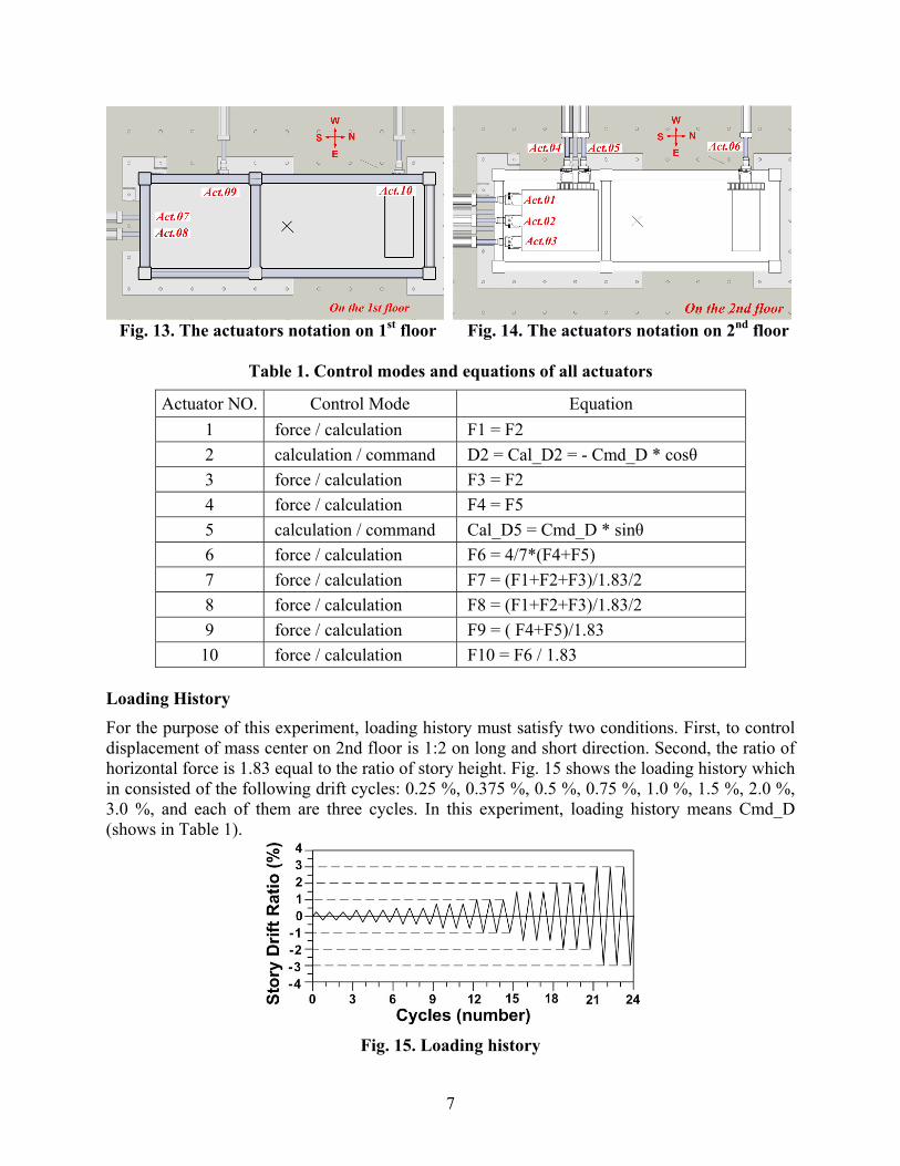
Control methods of 1st floor actuators. Fig. 13 and Fig. 14 are the notation of all actuators on 1st and 2nd floor. On the long direction of this specimen, we allocated Act.01 ~ Act.03 and Act.07 ~ Act.08, therefore the force ratio on 2nd floor to 1st floor shows as Eq. (7) and Eq. (8).
F7 = (F1+F2+F3)/1.83/2 (7) F8 = (F1+F2+F3)/1.83/2 (8)
In the same way, on short direction of this specimen, we allocated Act.04 ~ Act.06 and Act.09 ~ Act.010, hence the force ratio on 2nd floor to 1st floor shows as Eq. 9 and Eq. 10.
F9 =(F4+F5)/1.83 (9) F10=F6/1.83 (10)
7
Fig. 13. The actuators notation on 1st floor Fig. 14. The actuators notation on 2nd floor
Table 1. Control modes and equations of all actuators
Actuator NO. Control Mode Equation 1 force / calculation F1 = F2 2 calculation / command D2 = Cal_D2 = - Cmd_D * cosθ 3 force / calculation F3 = F2 4 force / calculation F4 = F5 5 calculation / command Cal_D5 = Cmd_D * sinθ 6 force / calculation F6 = 4/7*(F4+F5) 7 force / calculation F7 = (F1+F2+F3)/1.83/2 8 force / calculation F8 = (F1+F2+F3)/1.83/2 9 force / calculation F9 = ( F4+F5)/1.83 10 force / calculation F10 = F6 / 1.83
Loading History For the purpose of this experiment, loading history must satisfy two conditions. First, to control displacement of mass center on 2nd floor is 1:2 on long and short direction. Second, the ratio of horizontal force is 1.83 equal to the ratio of story height. Fig. 15 shows the loading history which in consisted of the following drift cycles: 0.25 %, 0.375 %, 0.5 %, 0.75 %, 1.0 %, 1.5 %, 2.0 %, 3.0 %, and each of them are three cycles. In this experiment, loading history means Cmd_D (shows in Table 1).
Fig. 15. Loading history
8
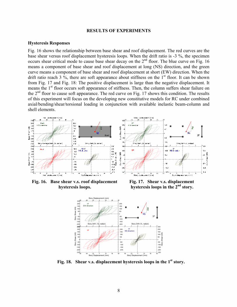
RESULTS OF EXPERIMENTS Hysteresis Responses Fig. 16 shows the relationship between base shear and roof displacement. The red curves are the base shear versus roof displacement hysteresis loops. When the drift ratio is -3 %, the specimen occurs shear critical mode to cause base shear decay on the 2nd floor. The blue curve on Fig. 16 means a component of base shear and roof displacement at long (NS) direction, and the green curve means a component of base shear and roof displacement at short (EW) direction. When the drift ratio reach 3 %, there are soft appearance about stiffness on the 1st floor. It can be shown from Fig. 17 and Fig. 18: The positive displacement is large than the negative displacement. It means the 1st floor occurs soft appearance of stiffness. Then, the column suffers shear failure on the 2nd floor to cause soft appearance. The red curve on Fig. 17 shows this condition. The results of this experiment will focus on the developing new constitutive models for RC under combined axial/bending/shear/torsional loading in conjunction with available inelastic beam-column and shell elements.
Fig. 16. Base shear v.s. roof displacement Fig. 17. Shear v.s. displacement
hysteresis loops. hysteresis loops in the 2nd story.
-69 -46 -23 0 23 46 69Story Displacement (mm)
-2500-2000-1500-1000-500
0500
1000150020002500
Stor
ySh
ear(
kN)
1F
-3 -2 -1 0 1 2 3Story Drift (%, radian)
-2000-1500-1000-5000500100015002000
-46 -23 0 23 46 69Story Displacement (mm)
1FNS direction
-2500-2000-1500-1000-50005001000150020002500
Stor
ySh
ear(
kN)
-2500-2000-1500-1000-500
0500
1000150020002500
Stor
ySh
ear(
kN)
1FEW direction
-69 -46 -23 0 23 46 69Story Displacement (mm)
-2000-1500-1000-5000500100015002000
-2 -1 0 1 2 3Story Drift (%, radian)
1FNS
EW
Fig. 18. Shear v.s. displacement hysteresis loops in the 1st story.
9
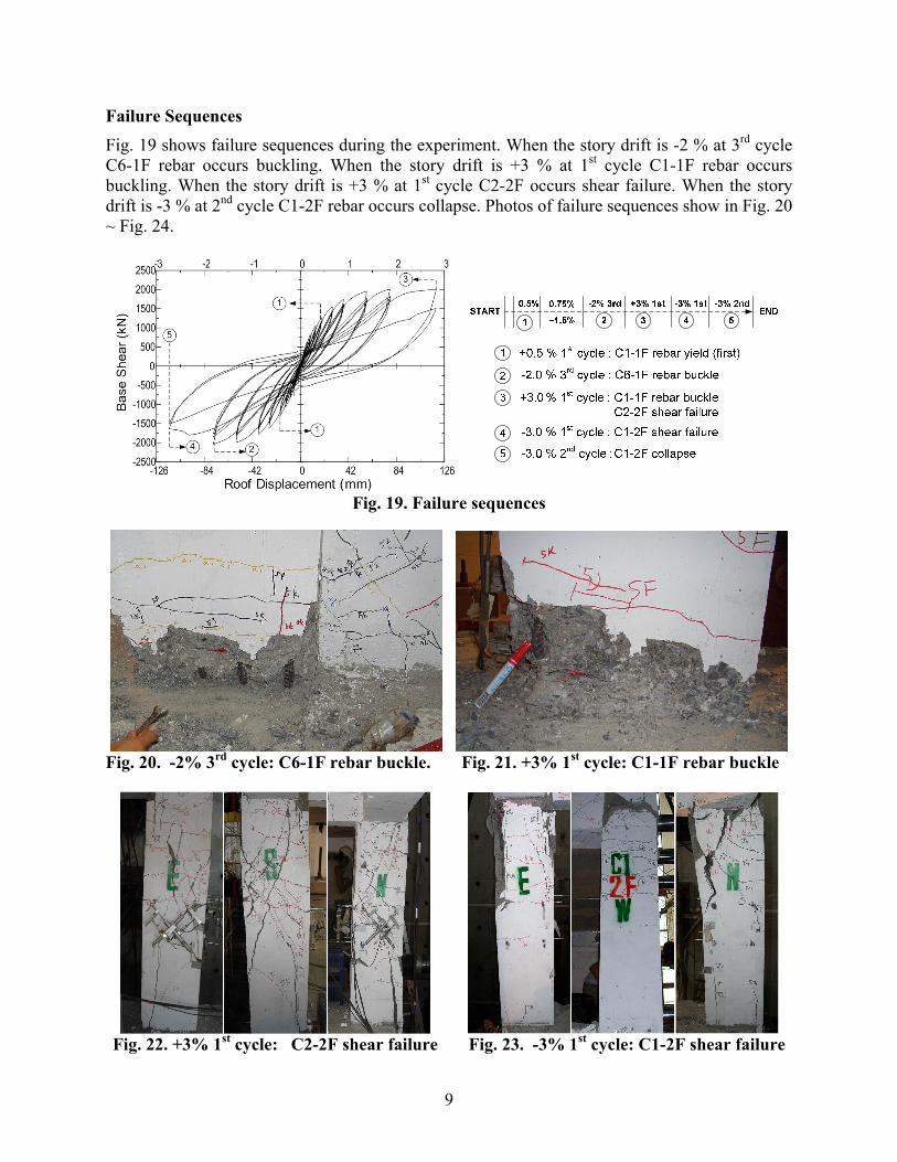
Failure Sequences
Fig. 19 shows failure sequences during the experiment. When the story drift is -2 % at 3rd cycle C6-1F rebar occurs buckling. When the story drift is +3 % at 1st cycle C1-1F rebar occurs buckling. When the story drift is +3 % at 1st cycle C2-2F occurs shear failure. When the story drift is -3 % at 2nd cycle C1-2F rebar occurs collapse. Photos of failure sequences show in Fig. 20 ~ Fig. 24.
Fig. 19. Failure sequences
Fig. 20. -2% 3rd cycle: C6-1F rebar buckle. Fig. 21. +3% 1st cycle: C1-1F rebar buckle
Fig. 22. +3% 1st cycle: C2-2F shear failure Fig. 23. -3% 1st cycle: C1-2F shear failure
10
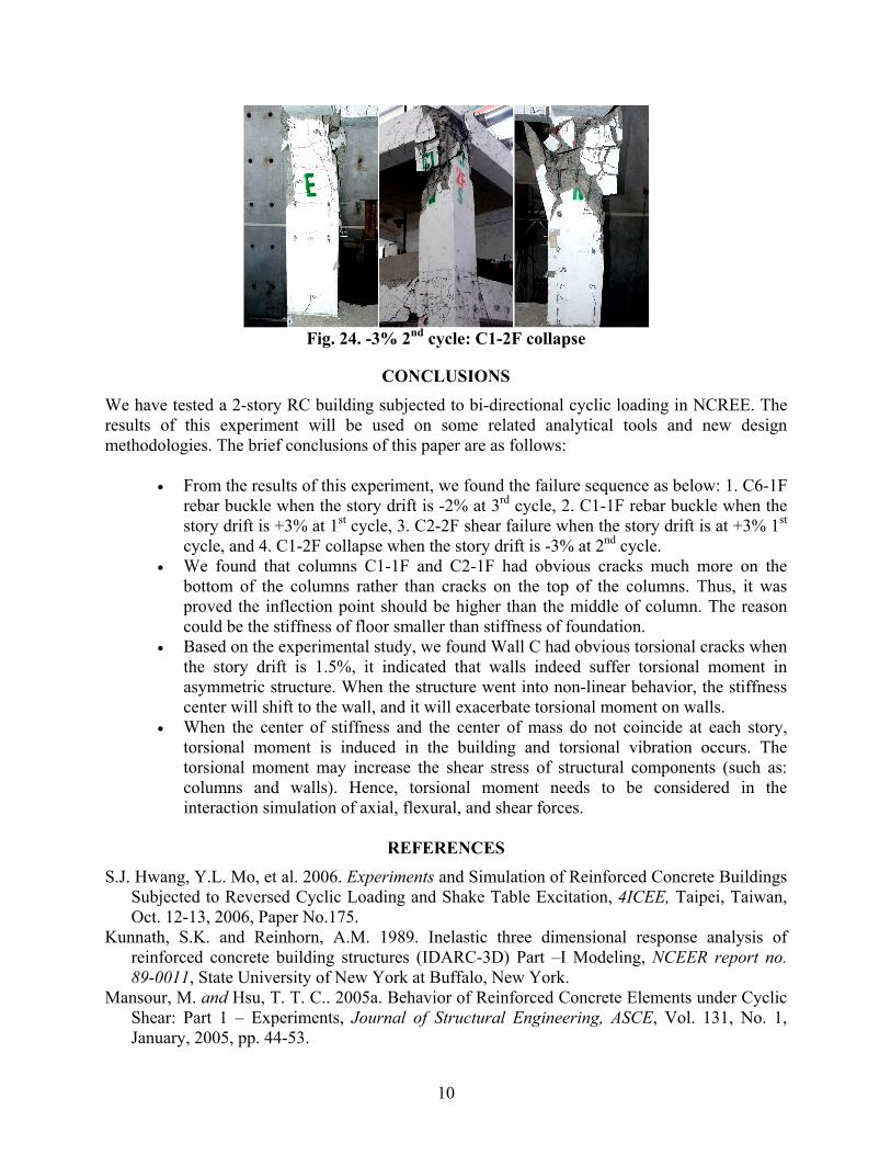
Fig. 24. -3% 2nd cycle: C1-2F collapse
CONCLUSIONS
We have tested a 2-story RC building subjected to bi-directional cyclic loading in NCREE. The results of this experiment will be used on some related analytical tools and new design methodologies. The brief conclusions of this paper are as follows:
• From the results of this experiment, we found the failure sequence as below: 1. C6-1F
rebar buckle when the story drift is -2% at 3rd cycle, 2. C1-1F rebar buckle when the story drift is +3% at 1st cycle, 3. C2-2F shear failure when the story drift is at +3% 1st cycle, and 4. C1-2F collapse when the story drift is -3% at 2nd cycle.
• We found that columns C1-1F and C2-1F had obvious cracks much more on the bottom of the columns rather than cracks on the top of the columns. Thus, it was proved the inflection point should be higher than the middle of column. The reason could be the stiffness of floor smaller than stiffness of foundation.
• Based on the experimental study, we found Wall C had obvious torsional cracks when the story drift is 1.5%, it indicated that walls indeed suffer torsional moment in asymmetric structure. When the structure went into non-linear behavior, the stiffness center will shift to the wall, and it will exacerbate torsional moment on walls.
• When the center of stiffness and the center of mass do not coincide at each story, torsional moment is induced in the building and torsional vibration occurs. The torsional moment may increase the shear stress of structural components (such as: columns and walls). Hence, torsional moment needs to be considered in the interaction simulation of axial, flexural, and shear forces.
REFERENCES
S.J. Hwang, Y.L. Mo, et al. 2006. Experiments and Simulation of Reinforced Concrete Buildings Subjected to Reversed Cyclic Loading and Shake Table Excitation, 4ICEE, Taipei, Taiwan, Oct. 12-13, 2006, Paper No.175.
Kunnath, S.K. and Reinhorn, A.M. 1989. Inelastic three dimensional response analysis of reinforced concrete building structures (IDARC-3D) Part –I Modeling, NCEER report no. 89-0011, State University of New York at Buffalo, New York.
Mansour, M. and Hsu, T. T. C.. 2005a. Behavior of Reinforced Concrete Elements under Cyclic Shear: Part 1 – Experiments, Journal of Structural Engineering, ASCE, Vol. 131, No. 1, January, 2005, pp. 44-53.