experimental and numerical assessment … experimental and numerical assessment of dissipative...
TRANSCRIPT

1
EXPERIMENTAL AND NUMERICAL ASSESSMENT OF DISSIPATIVE
CONNECTIONS FOR PRECAST STRUCTURES WITH CLADDING PANELS
Fabio Biondini1, Bruno Dal Lago
2 and Giandomenico Toniolo
3
ABSTRACT
The stability of the cladding wall panels of precast structures under seismic action can be ensured by means of a
dissipative system of connections in between the panels that allows to control the level of forces and to limit the
displacements. The connection system consists of friction-based or plasticity-based devices inserted into appropriate
recesses within the joints between vertical or horizontal panels, which are connected to the structure through a
statically determined arrangement. By activating the devices, the cladding panels become integral part of the whole
façade, making it much stiffer up to the limit force associated with the friction threshold or yielding of the devices.
The paper presents the technological choices of materials and shapes that ensure a stable hysteretic behaviour of
dissipative devices based on friction and/or plasticity and shows the results of monotonic and cyclic experimental
tests performed on both single connectors and structural sub-assemblies consisting of two full scale panels. Finally,
the results of non-linear dynamic analyses carried out on a single story precast concrete frame building show the
seismic performance of the dual frame/wall system with dissipative connections between the panels.
INTRODUCTION
Recent earthquakes occurred in Southern Europe showed inadequate behaviour of the standard connection systems
of cladding panels to precast buildings (Menegotto 2009, Colombo & Toniolo 2012, Savoia et al. 2012). A research
activity is ongoing at European level within the project SAFECLADDING to address a proper seismic design of
precast structures with cladding panels and to propose innovative systems of connections. In particular, the use of
dissipative connection devices can ensure the stability of the cladding panels under seismic action and improve the
seismic performance of the earthquake resisting system by providing energy dissipation capacity under controlled
forces with limited displacements (Biondini et al. 2013a).
Several types of dissipative connections specifically designed to be used in between precast concrete panels
have been studied within the SAFECLADDING project. In this paper, Friction Based Devices that dissipate energy
through friction and Multiple Slit Devices that dissipate energy through plasticity, are considered. These devices
are inserted into appropriate recesses within the joints between vertical or horizontal cladding panels, which are
connected to the structure through a statically determined arrangement. In this way, the activation of the panel-to-
panel connectors makes the panels integral part of the whole façade up to the limit force associated with the friction
threshold or yielding of the devices.
The technological features of the dissipative devices and the results of monotonic and cyclic experimental
tests performed on both single connectors and structural sub-assemblies consisting of two full scale panels, are
1 Associate Professor, Department of Civil and Environmental Engineering, Politecnico di Milano, [email protected]
2 PhD student, Department of Civil and Environmental Engineering, Politecnico di Milano, [email protected]
3 Full Professor, Department of Civil and Environmental Engineering, Politecnico di Milano, [email protected]

2
presented. The aim of the tests is to investigate the hysteretic behaviour of the devices and to identify the optimal
technological configuration of the connections to ensure performance and operability under seismic events.
Non-linear dynamic analyses of a single storey precast concrete frame building with vertical cladding
panels are also carried out to show the improved seismic performance of dual frame/wall systems with dissipative
connections between panels and to highlight the importance of an effective diaphragm action of the roof system to
fully exploit the beneficial effects of dissipative connection systems.
TEST SETUP
Cyclic experimental tests have been performed on both single dissipative connectors and structural sub-assemblies
consisting of two full scale panels.
The tests on single devices have been carried out on the mono-axial ± 1000 kN Schenck test machine at
the Laboratorio Prove e Materiali of Politecnico di Milano and subjected to imposed displacement histories. The
connections are tightened through bolts to a strong support made by two L-shaped HEA steel profiles welded
together. The L-shaped profiles are then tightened to the machine through nailed thick steel plates provided with
large diameter bolts. Fig.1a shows a picture of the test setup with a device under testing.
The panel sub-assembly test setup shown in Fig.1b is made of two single layer concrete panels
129×323×16cm, with an aspect ratio of 2,5. The panels are provided with an upper passing vertical slot in the
middle of the panel width, providing a vertical lever arm from the bottom panel-to-foundation connection to
the top panel-to-beam connection of about 260 cm. Three recesses are placed at 1/4, 2/4 and 3/4 of the
vertical lever arm at each side of the panels to connect the dissipative devices. The top panel connection is
made with round holes hosting steel pins that link the panels to the steel articulated frame through which the
imposed displacements are transmitted to the panels. The frame is made with two HEA columns hinged both
at the bottom with a strong steel beam and at the top with a double UPN beam surrounding the panels. The
hinges are made by steel pins and forks. The frame is connected to the horizontal jack fixed to the strong
steel braced reaction frame of the lab at a height of 270 cm, in axis with the beam-to-column pins. A lateral
displacement retainer system has been installed in correspondence of the steel beam and attached to it with
steel spheres that are fixed to lateral stiff retaining frames. Two vertical long slots are cut in the UPN profiles
in order to locate the panel-to-beam connection pins. The panel-to-foundation connection is also hinged with
pin and forks. Five different cyclic protocols have been used. Three protocols consist of increasing amplitude
displacements, expecting to provide information about the evolution of the connection behaviour and its low-cycle
stability. Two protocols consist of constant large amplitude displacements cycled several times in order to
investigate the oligo-cyclic stability of the connection subjected to large deformations.
(a) (b)
Figure 1. Test setup: (a) single device and (b) panel structural sub-assembly
F. Biondini, B. Dal Lago & G. Toniolo
3
FRICTION BASED DEVICE
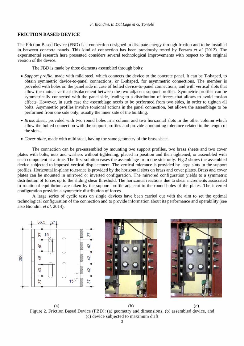
The Friction Based Device (FBD) is a connection designed to dissipate energy through friction and to be installed
in between concrete panels. This kind of connection has been previously tested by Ferrara et al (2012). The
experimental research here presented considers several technological improvements with respect to the original
version of the device.
The FBD is made by three elements assembled through bolts:
Support profile, made with mild steel, which connects the device to the concrete panel. It can be T-shaped, to
obtain symmetric device-to-panel connections, or L-shaped, for asymmetric connections. The member is
provided with holes on the panel side in case of bolted device-to-panel connections, and with vertical slots that
allow the mutual vertical displacement between the two adjacent support profiles. Symmetric profiles can be
symmetrically connected with the panel side, leading to a distribution of forces that allows to avoid torsion
effects. However, in such case the assemblage needs to be performed from two sides, in order to tighten all
bolts. Asymmetric profiles involve torsional actions in the panel connection, but allows the assemblage to be
performed from one side only, usually the inner side of the building.
Brass sheet, provided with two round holes in a column and two horizontal slots in the other column which
allow the bolted connection with the support profiles and provide a mounting tolerance related to the length of
the slots.
Cover plate, made with mild steel, having the same geometry of the brass sheet.
The connection can be pre-assembled by mounting two support profiles, two brass sheets and two cover
plates with bolts, nuts and washers without tightening, placed in position and then tightened, or assembled with
each component at a time. The first solution eases the assemblage from one side only. Fig.2 shows the assembled
device subjected to imposed vertical displacement. The vertical tolerance is provided by large slots in the support
profiles. Horizontal in-plane tolerance is provided by the horizontal slots on brass and cover plates. Brass and cover
plates can be mounted in mirrored or inverted configuration. The mirrored configuration yields to a symmetric
distribution of forces up to the sliding shear threshold. The horizontal reactions due to shear increments associated
to rotational equilibrium are taken by the support profile adjacent to the round holes of the plates. The inverted
configuration provides a symmetric distribution of forces.
A large series of cyclic tests on single devices have been carried out with the aim to set the optimal
technological configuration of the connection and to provide information about its performance and operability (see
also Biondini et al. 2014).
(a) (b) (c)
Figure 2. Friction Based Device (FBD): (a) geometry and dimensions, (b) assembled device, and
(c) device subjected to maximum drift
4
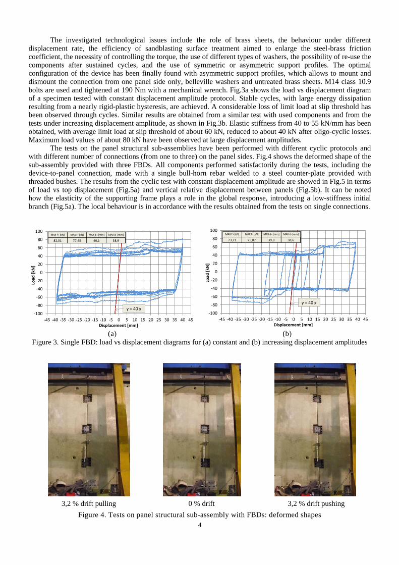
The investigated technological issues include the role of brass sheets, the behaviour under different displacement rate, the efficiency of sandblasting surface treatment aimed to enlarge the steel-brass friction coefficient, the necessity of controlling the torque, the use of different types of washers, the possibility of re-use the components after sustained cycles, and the use of symmetric or asymmetric support profiles. The optimal configuration of the device has been finally found with asymmetric support profiles, which allows to mount and dismount the connection from one panel side only, belleville washers and untreated brass sheets. M14 class 10.9 bolts are used and tightened at 190 Nm with a mechanical wrench. Fig.3a shows the load vs displacement diagram of a specimen tested with constant displacement amplitude protocol. Stable cycles, with large energy dissipation resulting from a nearly rigid-plastic hysteresis, are achieved. A considerable loss of limit load at slip threshold has been observed through cycles. Similar results are obtained from a similar test with used components and from the tests under increasing displacement amplitude, as shown in Fig.3b. Elastic stiffness from 40 to 55 kN/mm has been obtained, with average limit load at slip threshold of about 60 kN, reduced to about 40 kN after oligo-cyclic losses. Maximum load values of about 80 kN have been observed at large displacement amplitudes.
The tests on the panel structural sub-assemblies have been performed with different cyclic protocols and with different number of connections (from one to three) on the panel sides. Fig.4 shows the deformed shape of the sub-assembly provided with three FBDs. All components performed satisfactorily during the tests, including the device-to-panel connection, made with a single bull-horn rebar welded to a steel counter-plate provided with threaded bushes. The results from the cyclic test with constant displacement amplitude are showed in Fig.5 in terms of load vs top displacement (Fig.5a) and vertical relative displacement between panels (Fig.5b). It can be noted how the elasticity of the supporting frame plays a role in the global response, introducing a low-stiffness initial branch (Fig.5a). The local behaviour is in accordance with the results obtained from the tests on single connections.
-100
-80
-60
-40
-20
0
20
40
60
80
100
-45 -40 -35 -30 -25 -20 -15 -10 -5 0 5 10 15 20 25 30 35 40 45
Load
[kN
]
Displacement [mm]
y = 40 x
MAX F+ [kN] MAX F- [kN] MAX d+ [mm] MAX d- [mm]
82,01 77,45 40,1 38,9
-100
-80
-60
-40
-20
0
20
40
60
80
100
-45 -40 -35 -30 -25 -20 -15 -10 -5 0 5 10 15 20 25 30 35 40 45
Load
[kN
]
Displacement [mm]
y = 40 x
MAX F+ [kN] MAX F- [kN] MAX d+ [mm] MAX d- [mm]
73,71 75,87 39,0 38,6
(a) (b)
Figure 3. Single FBD: load vs displacement diagrams for (a) constant and (b) increasing displacement amplitudes
3,2 % drift pulling 0 % drift 3,2 % drift pushing
Figure 4. Tests on panel structural sub-assembly with FBDs: deformed shapes
F. Biondini, B. Dal Lago & G. Toniolo
5
-120
-100
-80
-60
-40
-20
0
20
40
60
80
100
120
-100 -80 -60 -40 -20 0 20 40 60 80 100
Load
[kN
]
Top displacement [mm]
y = 1,5 x
y = 8 x
MAX F+ [kN] MAX F- [kN] MAX d+ [mm] MAX d- [mm]
119,11 105,87 85,4 85,2
-120
-100
-80
-60
-40
-20
0
20
40
60
80
100
120
-40 -30 -20 -10 0 10 20 30 40
Load
[kN
]
Vertical relative displacement [mm]
y = 120 x
MAX F+ [kN] MAX F- [kN] MAX d+ [mm] MAX d- [mm]
119,11 105,87 31,7 30,2
(a) (b)
Figure 5. Tests on panel structural sub-assembly with FBDs: load vs (a) top displacement and (b) vertical relative
displacement diagrams
MULTIPLE SLIT DEVICE
Multiple Slit Devices (MSD) are steel plates with slits of various shapes and sizes which realize a set of elementary
beams. The slits allow to modify the shear-type behaviour of the rectangular plate to the flexural-type behaviour of
the elementary beams, which allows larger energy dissipation capacities (Schultz et al. 1994). MSDs have been
developed as dissipative connections mainly for steel structures, and can be considered as an evolution of the so-
called ADAS devices (Aiken et al. 1993, Soong & Spencer Jr 2002), where slender butterfly-shaped steel beams
are linked together and dissipate energy through plasticity. Several types of plate dissipative devices have been
tested by Chan et al. (2008), including MSDs. Ma et al. (2010) developed design procedures and experimental tests
on MSDs with different beam depth profiles, including constant and butterfly-shaped profiles. Shape optimization
was used by Ghabraie et al. (2010) to identify an optimized MSD with hourglass-shaped beams.
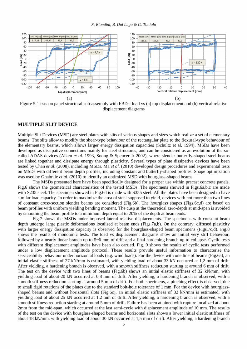
The MSDs presented here have been specifically designed for a proper use within precast concrete panels.
Fig.6 shows the geometrical characteristics of the tested MSDs. The specimens showed in Figs.6a,b,c are made
with S235 steel. The specimen showed in Fig.6d is made with S355 steel. All the plates have been designed to have
similar load capacity. In order to maximize the area of steel supposed to yield, devices with not more than two lines
of constant cross-section slender beams are considered (Fig.6b). The hourglass shapes (Figs.6c,d) are based on
beam profiles with uniform yielding bending moment. The cusp at the theoretical zero-depth at mid-span is avoided
by smoothing the beam profile to a minimum depth equal to 20% of the depth at beam ends.
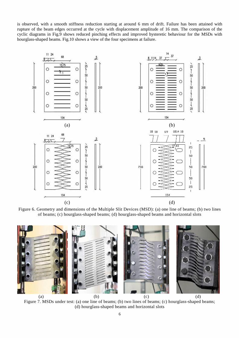
Fig.7 shows the MSDs under imposed lateral relative displacements. The specimens with constant beam
depth undergo large plastic deformations localised at beam ends (Figs.7a,b). On the contrary, diffused plasticity
with larger energy dissipation capacity is observed for the hourglass-shaped beam specimens (Figs.7c,d). Fig.8
shows the results of monotonic tests. The load vs displacement diagrams show an initial very stiff behaviour,
followed by a nearly linear branch up to 5~6 mm of drift and a final hardening branch up to collapse. Cyclic tests
with different displacement amplitudes have been also carried. Fig. 9 shows the results of cyclic tests performed
under a low displacement amplitude protocol. These results provide useful information to characterise the
serviceability behaviour under horizontal loads (e.g. wind loads). For the device with one line of beams (Fig.6a), an
initial elastic stiffness of 27 kN/mm is estimated, with yielding load of about 33 kN occurred at 1,2 mm of drift.
After yielding, a hardening branch is observed, with a smooth stiffness reduction starting at around 6 mm of drift.
The test on the device with two lines of beams (Fig.6b) shows an initial elastic stiffness of 32 kN/mm, with
yielding load of about 20 kN occurred at 0,8 mm of drift. After yielding, a hardening branch is observed, with a
smooth stiffness reduction starting at around 5 mm of drift. For both specimens, a pinching effect is observed, due
to small rigid rotations of the plates due to the standard bolt-hole tolerance of 1 mm. For the device with hourglass-
shaped beams and without horizontal slots (Fig.6c), an initial elastic stiffness of 32 kN/mm is estimated, with
yielding load of about 25 kN occurred at 1,2 mm of drift. After yielding, a hardening branch is observed, with a
smooth stiffness reduction starting at around 5 mm of drift. Failure has been attained with rupture localized at about
2mm from the mid-span, which occurred at the last semi-cycle with displacement amplitude of 10 mm. The results
of the test on the device with hourglass-shaped beams and horizontal slots shows a lower initial elastic stiffness of
about 18 kN/mm, with yielding load of about 30 kN occurred at 1,5 mm of drift. After yielding, a hardening branch
6
is observed, with a smooth stiffness reduction starting at around 6 mm of drift. Failure has been attained with
rupture of the beam edges occurred at the cycle with displacement amplitude of 16 mm. The comparison of the
cyclic diagrams in Fig.9 shows reduced pinching effects and improved hysteretic behaviour for the MSDs with
hourglass-shaped beams. Fig.10 shows a view of the four specimens at failure.
(a) (b)
(c) (d)
Figure 6. Geometry and dimensions of the Multiple Slit Devices (MSD): (a) one line of beams; (b) two lines
of beams; (c) hourglass-shaped beams; (d) hourglass-shaped beams and horizontal slots
(a) (b) (c) (d)
Figure 7. MSDs under test: (a) one line of beams; (b) two lines of beams; (c) hourglass-shaped beams;
(d) hourglass-shaped beams and horizontal slots

F. Biondini, B. Dal Lago & G. Toniolo
7
0
20
40
60
80
100
120
0 3 6 9 12 15 18 21 24 27 30 33 36 39 42
Load
[kN
]
Displacement [mm]
1-Slits2-SlitsHourglassHourglass+Slots
y = 12 x
y = 1,4 x
Figure 8. Monotonic tests on single MSDs
-120
-100
-80
-60
-40
-20
0
20
40
60
80
100
120
-21 -18 -15 -12 -9 -6 -3 0 3 6 9 12 15 18 21
Load
[kN
]
Displacement [mm]
MAX F+ [kN] MAX F- [kN] MAX d+ [mm] MAX d- [mm]
78,50 79,67 9,40 9,20
y = 27 x
-120
-100
-80
-60
-40
-20
0
20
40
60
80
100
120
-21 -18 -15 -12 -9 -6 -3 0 3 6 9 12 15 18 21
Loa
d [
kN]
Displacement [mm]
y = 32 x
MAX F+ [kN] MAX F- [kN] MAX d+ [mm] MAX d- [mm]
83,69 80,91 9,48 8,95
(a) (b)
-120
-90
-60
-30
0
30
60
90
120
-21 -18 -15 -12 -9 -6 -3 0 3 6 9 12 15 18 21
Loa
d [
kN]
Displacement [mm]
MAX F+ [kN] MAX F- [kN] MAX d+ [mm] MAX d- [mm]
67,48 69,21 14,63 14,47
y = 28 x
-120
-90
-60
-30
0
30
60
90
120
-21 -18 -15 -12 -9 -6 -3 0 3 6 9 12 15 18 21
Loa
d [
kN
]
Displacement [mm]
MAX F+ [kN] MAX F- [kN] MAX d+ [mm] MAX d- [mm]
81,53 86,12 20,25 18,45
y = 18 x
(c) (d)
1Figure 9. Cyclic tests on single MSDs: load vs displacement diagrams at low amplitude cycles for the
devices with (a) one line of beams, (b) two lines of beams, (c) hourglass-shaped beams,
(d) hourglass-shaped beams and horizontal slots
The hysteretic behaviour at larger displacement amplitudes is shown in Fig.11 with reference to cyclic tests
carried out on the two-panel sub-assembly provided with one MSD mounted on UPN support profiles. The results
indicate a good hysteretic behaviour, with significant energy dissipation capacity, and highlight that the cyclic
response of this type of connection may become unstable at large drift. The local behaviour of the connection is in
accordance with the results of the cyclic tests performed on single devices (Biondini et al. 2014).

8
(a) (b) (c) (d)
Figure 10. MSDs at failure: (a) one line of beams; (b) two lines of beams; (c) hourglass-shaped beams;
(d) hourglass-shaped beams and horizontal slots
-60
-40
-20
0
20
40
60
-40 -30 -20 -10 0 10 20 30 40
Load
[kN
]
Vertical relative displacement [mm]
y = 10 x
MAX F+ [kN] MAX F- [kN] MAX d+ [mm] MAX d- [mm]
50,10 44,00 34,0 32,8
(a) (b)
Figure 11. Tests on panel structural sub-assembly with a single MSD: (a) assembled connection; (b) load vs vertical
relative displacement diagrams
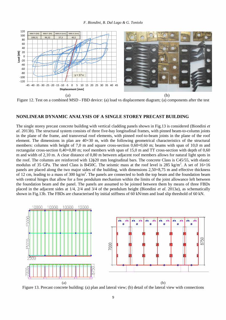
A preliminary pilot cyclic test on a device with combined MSD and FBD has been also carried out. The UPN
support profiles have been provided with 20 mm vertical slots and the bolts have been equipped with brass square
washers at the plate-support interface and with belleville washers at the exterior side. Tightening has been
performed with a mechanical wrench at 100 Nm. The results of the tests are shown in Fig.12a. It can be noted that
the displacement capacity of the MSD can be increased by calibrating the slip threshold of the FBD within the
hardening branch of the multi-slit plate. This allows a larger dissipation of energy and a more clear failure
mechanism of the MSD when the vertical slot stroke is reached. Fig.12b shows the components of the connection
after testing.
F. Biondini, B. Dal Lago & G. Toniolo
9
-120
-100
-80
-60
-40
-20
0
20
40
60
80
100
120
-45 -40 -35 -30 -25 -20 -15 -10 -5 0 5 10 15 20 25 30 35 40 45
Load
[kN
]
Displacement [mm]
y = 17 x
MAX F+ [kN] MAX F- [kN] MAX d+ [mm] MAX d- [mm]
108,31 96,32 37,3 40,5
(a) (b)
Figure 12. Test on a combined MSD - FBD device: (a) load vs displacement diagram; (a) components after the test
NONLINEAR DYNAMIC ANALYSIS OF A SINGLE STOREY PRECAST BUILDING
The single storey precast concrete building with vertical cladding panels shown in Fig.13 is considered (Biondini et
al. 2013b). The structural system consists of three five-bay longitudinal frames, with pinned beam-to-column joints
in the plane of the frame, and transversal roof elements, with pinned roof-to-beam joints in the plane of the roof
element. The dimensions in plan are 40×30 m, with the following geometrical characteristics of the structural
members: columns with height of 7,0 m and square cross-section 0,60×0,60 m; beams with span of 10,0 m and
rectangular cross-section 0,40×0,80 m; roof members with span of 15,0 m and TT cross-section with depth of 0,60
m and width of 2,10 m. A clear distance of 0,80 m between adjacent roof members allows for natural light spots in
the roof. The columns are reinforced with 1220 mm longitudinal bars. The concrete Class is C45/55, with elastic
modulus of 35 GPa. The steel Class is B450C. The seismic mass at the roof level is 285 kg/m2. A set of 16+16
panels are placed along the two major sides of the building, with dimensions 2,50×8,75 m and effective thickness
of 12 cm, leading to a mass of 300 kg/m2. The panels are connected to both the top beam and the foundation beam
with central hinges that allow for a free pendulum mechanism within the limits of the joint allowance left between
the foundation beam and the panel. The panels are assumed to be jointed between them by means of three FBDs
placed in the adjacent sides at 1/4, 2/4 and 3/4 of the pendulum height (Biondini et al. 2013a), as schematically
shown in Fig.13b. The FBDs are characterised by initial stiffness of 60 kN/mm and load slip threshold of 60 kN.
(a) (b) Figure 13. Precast concrete building: (a) plan and lateral view; (b) detail of the lateral view with connections

10
The seismic behaviour of the precast frame/wall structural system with dissipative panel connections is
studied through non-linear dynamic analysis under horizontal ground motion in the main direction of the building.
The seismic action is represented by the registered accelerogram of the Tolmezzo earthquake (Friuli, Italy, 1971),
modified to comply with the elastic response spectrum provided by Eurocode 8 for soil type B (CEN-EN 1998-1,
2004) and scaled at the peak ground acceleration PGA = 0,32g (Fig.14). Columns are modelled by beam elements
with distributed plasticity based on the cross-sectional bending-moment curvature relationships under axial force.
The cyclic behaviour is based on the Takeda model (Takeda et al. 1970). Elastic behaviour is assumed for beams,
roof elements and panels, relying on their over-strength with respect to the capacity of the connections. An elastic-
perfectly plastic model is assumed for the FBDs. The non-linear analyses are performed for three case studies with
different stiffness of the roof diaphragm: (a) rigid diaphragm, imposed numerically; (b) deformable diaphragm,
with both ribs of the TT roof members hinged to the beams; (c) no diaphragm, with only one rib of the TT roof
members hinged to the beams. Figure 15 shows the hysteretic cycles associated to the local behaviour of a FBD for
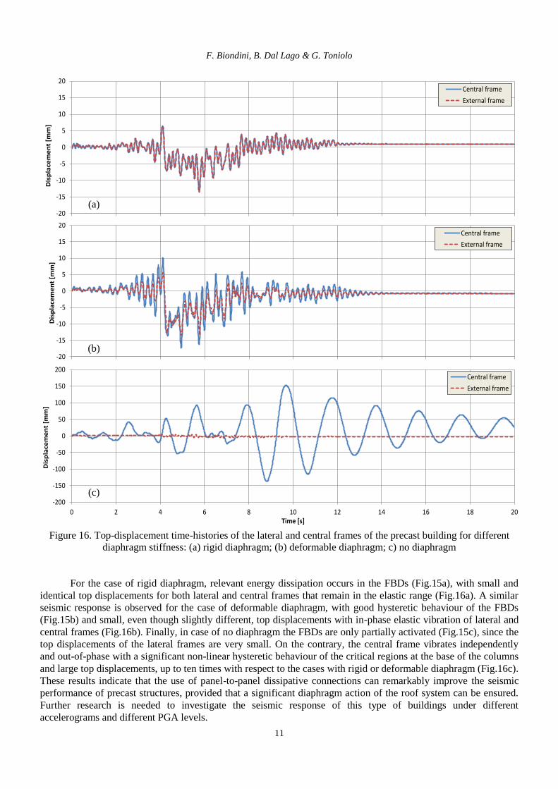
the three case studies. The global seismic response of the building is shown in Figure 16 in terms of top
displacement time-histories for both lateral and central frames.
(a) (b)
Figure 14. (a) Modified Tolmezzo accelerogram; b) Elastic response spectrum vs the EC8 spectrum for soil type B
-80
-60
-40
-20
0
20
40
60
80
-5 -4 -3 -2 -1 0 1 2 3 4 5
Load
[kN
]
Relative displacement [mm]
-80
-60
-40
-20
0
20
40
60
80
-5 -4 -3 -2 -1 0 1 2 3 4 5
Load
[kN
]
Relative displacement [mm]
-80
-60
-40
-20
0
20
40
60
80
-5 -4 -3 -2 -1 0 1 2 3 4 5
Load
[kN
]
Relative displacement [mm]
(a) (b) (c)
Figure 15. Hysteretic cycles of a FBD located at mid-height of the panels of the precast building for different
diaphragm stiffness: (a) rigid diaphragm; (b) deformable diaphragm; c) no diaphragm
F. Biondini, B. Dal Lago & G. Toniolo
11
-20
-15
-10
-5
0
5
10
15
20
0 2 4 6 8 10 12 14 16 18 20
Dis
pla
cem
en
t [m
m]
Time [s]
Central frame
External frame
-20
-15
-10
-5
0
5
10
15
20
0 2 4 6 8 10 12 14 16 18 20
Dis
pla
cem
en
t [m
m]
Time [s]
Central frame
External frame
-200
-150
-100
-50
0
50
100
150
200
0 2 4 6 8 10 12 14 16 18 20
Dis
pla
cem
en
t [m
m]
Time [s]
Central frame
External frame
Figure 16. Top-displacement time-histories of the lateral and central frames of the precast building for different
diaphragm stiffness: (a) rigid diaphragm; (b) deformable diaphragm; c) no diaphragm
For the case of rigid diaphragm, relevant energy dissipation occurs in the FBDs (Fig.15a), with small and
identical top displacements for both lateral and central frames that remain in the elastic range (Fig.16a). A similar
seismic response is observed for the case of deformable diaphragm, with good hysteretic behaviour of the FBDs
(Fig.15b) and small, even though slightly different, top displacements with in-phase elastic vibration of lateral and
central frames (Fig.16b). Finally, in case of no diaphragm the FBDs are only partially activated (Fig.15c), since the
top displacements of the lateral frames are very small. On the contrary, the central frame vibrates independently
and out-of-phase with a significant non-linear hysteretic behaviour of the critical regions at the base of the columns
and large top displacements, up to ten times with respect to the cases with rigid or deformable diaphragm (Fig.16c).
These results indicate that the use of panel-to-panel dissipative connections can remarkably improve the seismic
performance of precast structures, provided that a significant diaphragm action of the roof system can be ensured.
Further research is needed to investigate the seismic response of this type of buildings under different
accelerograms and different PGA levels.
(a)
(b)
(c)

12
CONCLUSIONS
The technological features and experimental mechanical characterization of friction-based and plasticity-based
dissipative devices, designed to be inserted in between precast concrete panels, have been presented. The
experimental investigation included monotonic and cyclic tests performed on both single connectors and structural
sub-assemblies consisting of two full scale panels. The results of the experimental tests highlighted the good
hysteretic behaviour and energy dissipation capacity of both friction-based and plasticity-based devices. Based on
the results, the seismic response of a single storey precast building with friction-based panel-to-panel connections
has been investigated by means of nonlinear dynamic analyses. The numerical results confirmed the remarkable
improvement of the seismic performance of precast structures based on the beneficial effects of dissipative
connections, which can provide suitable energy dissipation capacity and limit at the same time forces and
displacements when a significant diaphragm action of the roof system is ensured. The seismic behaviour of a full-scale structural prototype of a single story precast building with cladding
panels is currently under experimental investigation at the ELSA laboratory of the Joint Research Centre at Ispra,
Italy. The experimental campaign is part of the activities of the SAFECLADDING project and consists of several
cyclic and pseudo-dynamic tests of the structural prototype with different arrangements of vertical and horizontal
panels and different types of connections, including the friction-based dissipative device proposed in this paper.
ACKNOWLEDGEMENTS
This work has been developed within the framework of the European research project FP7-SME2012 SAFECLADDING:
Improved fastening systems of cladding wall panels of precast buildings in seismic zones (Grant Agreement no. 314122). Special
thanks to Marco Lamperti for his contribution to the development of the experimental tests. The contribution of Silvia Bianchi
and Giulia Marelli to the experimental activity is also acknowledged. BS Italia and Styl-Comp companies are gratefully
acknowledged for the careful production of specimens and setup members.
REFERENCES
Aiken ID, Nims DK, Whittaker AS, Kelly JM (1993) “Testing of passive energy dissipation systems”, Earthquake Spectra,
9(3): 335-370
Biondini F, Dal Lago B, Toniolo G (2014) “Connettori dissipativi ad attrito tra pannelli prefabbricati: sperimentazione e criteri
di impiego”, XXVII AICAP Congress, Bergamo, Italy, May 22 - 24 (In Italian)
Biondini F, Dal Lago B, Toniolo G (2013a) “Role of wall panel connections on the seismic performance of precast structures”,
Bulletin of Earthquake Engineering, 11(4): 1061-1081
Biondini F, Dal Lago B, Toniolo G (2013b) “Azione diaframma in strutture prefabbricate con pannelli di parete”, XV ANIDIS
Congress, Padova, Italy, June 30 - July 4 (In Italian)
CEN-EN 1998-1:2004 (2004) Eurocode 8: Design of structures for earthquake resistance – Part 1: General rules, seismic
actions and rules for buildings, European Committee for Standardization, Brussels, Belgium.
Chan RWK, Albermani F (2008) “Experimental study of steel slit damper for passive energy dissipation”, Engineering
Structures, 30(4): 1058-1066
Colombo A, Toniolo G (2012) “Precast concrete structures: the lesson learnt from L’Aquila earthquake”, Structural Concrete,
Vol. 13(2): 73-83
Ferrara L, Felicetti R, Toniolo G, Zenti C (2012) “Friction dissipative devices for cladding panels in precast buildings”,
European Journal of Environmental and Civil Engineering, 15(9): 1319-1338
Ghabraie K, Chan R, Huang X, Xie YM (2010) “Shape optimization of metallic yielding devices for passive mitigation of
seismic energy”, Engineering Structures, 32(8): 2258-2267
Ma X, Borchers E, Pena A, Krawinkler H, Billington S, Deierlein GG (2010) Design and behavior of steel shear plates with
openings as energy dissipating fuses, Report 173, Department of Civil and Environmental Engineering, Stanford
University, Stanford, CA, USA
Menegotto M (2009) “Observations on precast concrete structures of industrial buildings and warehouses”, Progettazione
sismica, Special Issue on the 2009 L’Aquila earthquake, 3: 149-153
Savoia M, Mazzotti C, Buratti N, Ferracuti B, Bovo M, Ligabue V, Vincenzi L (2012) “Damages and collapses in industrial
precast buildings after the Emilia earthquake”, Ingegneria Sismica, 29(2-3): 120-131
Schultz A E, Magana R A, Tadros M K, Huo X (1994) “Experimental study of joint connections in precast concrete walls”, 5th
U.S. National Conference on Earthquake Engineering, Chicago, USA, July 10-14, Vol. II: 579-587
Soong TT, Spencer Jr BF (2002) “Supplemental energy dissipation: state-of-the-art and state-of-the-practice”, Engineering
Structures, 24(3): 243-249
Takeda T, Sozen MA, Nielsen NN (1970) “Reinforced Concrete Response to Simulated Earthquakes”, Journal of the
Structural Division, ASCE, 96(12), 2557-2573