experimental and numerical investigation of hyper
TRANSCRIPT

Journal of Engineering Volume 23 August 2017 Number 8
56
Experimental and Numerical Investigation of Hyper Composite Plate Structure
Under Thermal and Mechanical Loadings
Mohsin Abdullah Al-Shammri Sahar Emad Abdullah
Assistant Professor Engineer
College of Engineering-University of Baghdad College of Engineering-University of Baghdad
Email:[email protected] Email:[email protected]
ABSTRACT
In this study eleven models of the rocket fins were made of hyper composite material with
different values of volume fraction of components (70%, 60%,50% for polyester, 40%,
30%,25%,20%,10% for fibers and 0%, 5%, 10%, 20%, 30%,40%for powder) to produce an
isotropic composite plate structure. The reinforcement of the matrix is done by mixing of the
polyester resin with the carbon fiber and carbon powder. Mechanical and thermal properties were
evaluated by conducting several tests. A concentrated load was applied on these models the effect of
adding the carbon powder on the maximum deflection and the effect of temperature on this
deflection were studied and discussed. The temperature range was suggested according to the matrix
ability and applications. The experimental results were verified numerically using ANSYS finite
element program. The results showed that the addition of carbon powder to the composite material
composed of polyester and glass fiber leads to increase the value of Young 's Modulus (maximum
value 6.36 GPa) and decrease the amount of maximum deflection. The maximum deflection was
increased with the increasing of temperature. The lowest value of maximum deflection was
occurred in the model composed of (50% polyester,30%glass fiber and 20% powder) which reached
to 1.56 mm. The comparison between experimental and numerical results showed a good agreement
between them.
Key words: rocket fins, hyper composite material, maximum deflection, thermal and mechanical
loads.
ميكانيكية والحراريةالل الاحمادراسة عملية وعذدية للصفائح المركبة الهجينة جحث جأثير
أ.م.د. محسن عبذ الله الشمري المهنذسة سحر عماد عبذ الله باحثت اسخار ساعذ
خاعت بغذاد-خاعت بغذاد وت اهذست-هذستوت ا
الخلاصة %70 ) راث وسىس حدت خخفت ادة شوبت هدتصعج ىرج صعاف اصاسوخ احذ عشش ف هزا ابحث ح حصع
لأخاج باودس ( %40,%30 ,%20 ,%10 ,%5 ,%0لااف و %10,%20,%25,%30 ,%40بىسخش و 50%,60%
ىاىت اخىاص ا دسسج باسخخذا ااف اضخاج ع باودس اىاسبى. لىج اادة الاساطا . صفحت ادة خاثت اخىاص
الص احشاف ها ع دساست حأثش وح حسابح خشوض ع هز اارج خلاي اخشاء عذة اخخباساث. سط واحشاست
ح ا ذي دسخاث احشاسة وا بالاعخاد ع لذسة اىاد اسخخذت واخطبماث اعت. دسخت احشاسة ع ره الاحشاف.
ادة اىىت اشوبت ادة اىاسبى إضافت سحىق أ اخائح أظهشث .اسض اخحمك اخائح اعت عذدا باسخخذا بشاح
.حشافوخفض احذ الألص لا GPa 6.36حث وص ا عا اشوت صادة ؤد إ والأاف اضخاخت ابىسخش
لت لأحشاف الألص أل وخذ ا. وطت ع اىرجبضادة ل دسخاث احشاسة اس لاحشاف احذ الألص اصدادث لت
ا .(mm 1.56 ) حث بغج% باودس واسبى( 05% ااف صخاج و05% بىسخش و05ىى )اىرج ظهشث ف ا
.ابج ا هان احفالا خذا به واعذدت اذساست اعت ب اماست

Journal of Engineering Volume 23 August 2017 Number 8
57
صعاف اصاسوخ, ىاد شوبت هدت, ألص احشاف, احاي حشاست وىاىت الكلمات الرئيسية:
1. INTRODUCTION
1.1 Hyper Composite Material
Hyper composite material is more advanced composite as compared to established fiber-
reinforced polymer (FRP). Hyper composite material can have more advanced than single
reinforcing phase with a single matrix phase or multiple matrix phases with single reinforcing phase
or multiple matrix phases with multiple reinforcing phase. It is possible to obtain the advantage of
the various fibers while coincidental mitigating their undesirable qualities by combining two or
more kinds of fibers, Mutsuyoshil and Aravinthan,2010.
There are three kinds of hyper composites: matrix hyper, fiber hyper and interfacial hyper. The
matrix hyper means combining of two or more type of resin in one composite. The fiber hyper
means different fibers using in one textile while interfacial hyper means combining of two or more
type of fiber bundles with various surface treatments. The mechanical properties of these hyper
composites (high specific strength, high specific stiffness, energy absorption, low density and
corrosive resistance) variegated according to changing volume ratio and stacking succession of
different plies Mohammed, 2013.
Ibrahim, 2011, studied the influence of reinforcing polymer with graphite and glass particles. The
results showed that the hyper composite material (20% glass, 30% graphite, 50% epoxy) has higher
flexural strength than polymer matrix material. Smait and Mohammed, 2012, studied
experimentally the effect of graphite filler on the mechanical behavior of glass – polyester
composite material at (30% volume fraction). The results showed that the mechanical properties
were improved with the increasing of the graphite filler to (7.5%) and it was regressed above this
content. Sakthivel and Ragendran, 2014, fabricated hyper composite material using natural and
glass fiber. The results showed that the hyper composite material has higher mechanical properties
in the tensile, impact and flexural tests. Basim et.al, 2014, prepared hyper composite material using
epoxy resin and glass fiber with volume fraction of 6% and calcium carbonate as powder with
volume fraction 3% and 6%. The results showed that the increasing in hardness and flexural strength
is shown with the increasing of powder volume fraction and smaller particles size.
1.2 Thermal Effect on Composite Material
The environmental conditions have a significant effect on the physical and mechanical properties
of engineering materials, which is one of the basic things that should be taken into consideration. In
view of the properties of the composite material such as high strength to density ratio and high
thermal and electrical insulation and the urgent need to be used in a lot of military and engineering
fields such as aircraft, ships, rocket, hydrofoils and space vehicle which are subjected to change in
the ambient temperature. This changes in the temperature incite the researchers to study the effect of
temperature on the properties of these materials, Thanon, 2013.
Putic et.al, 2006, studied the effect of low and high temperature on the impact properties of glass-
epoxy composite. The impact strength was presented at three temperature levels. They showed that
the impact properties were higher at the elevated temperature and they were the smallest in low
temperature. Abbas, 2007, studied the influence of temperature on the young modulus, flexural

Journal of Engineering Volume 23 August 2017 Number 8
58
strength, impact strength and thermal conductivity of hyper composite material manufactured from
epoxy with glass fiber and carbon fiber at different temperature (23, 40 and 60) °C with volume
fraction of 30%. The results showed that young modulus is decreased with the increasing of the
temperature, but, the flexural strength, the impact strength and the thermal conductivity were
increased with the increasing of the temperature.AL-alkawi, et al, 2012, studied the effect of
temperature on the value of the ultimate tensile strength of composite material manufactured of
polyester as resin and E-glass woven fiber. The results showed that when the temperature was
increased the ultimate tensile strength was increased.
The goal of this research is to manufacture eleven model of Hybrid composite plate (rocket fin) and
study the mechanical and thermal properties of these models and then applying a concentrated load
to obtain the maximum deflection. In the other hand the thermal effect on this deflection is to be
investigated. These models were made of unsaturated polyester with different values of volume
fraction of fiber glass and carbon powder.
2. EXPERIMANTAL WORK
2.1 Materials
Unsaturated polyester was used as a matrix. It is viscous liquid, transparent and thermosetting
polymer type. It is converted to a solid state by mixing with the hardener (2% of polyester weight).
The type of fiber used is E-glass (chopped) and the type of powder is carbon powder (Avg.
Diameter:109.86 nm, Purity 99.997%).
2.2 Preparation of Mold and Manufacturing of Tensile Test Samples and Fins
The mold is manufactured of wood and glass so as to make the samples with the desired
dimensions [25 cm x 25 cm x 0.3 cm]. And then prepare the mold using wax to insure the clean and
smooth facing and also to easy the process of sample removal. Fig.1.
There are several methods to manufacture a composite structure. There are advantages and
disadvantages for each one of them. It has been using the hand lay out method to prepare the models
and samples because it is the simplest procedure to use and the way by which to obtain the samples
in different shapes and sizes. The models of rocket fin which have been manufactured in this
research are shown in the Fig. 2.
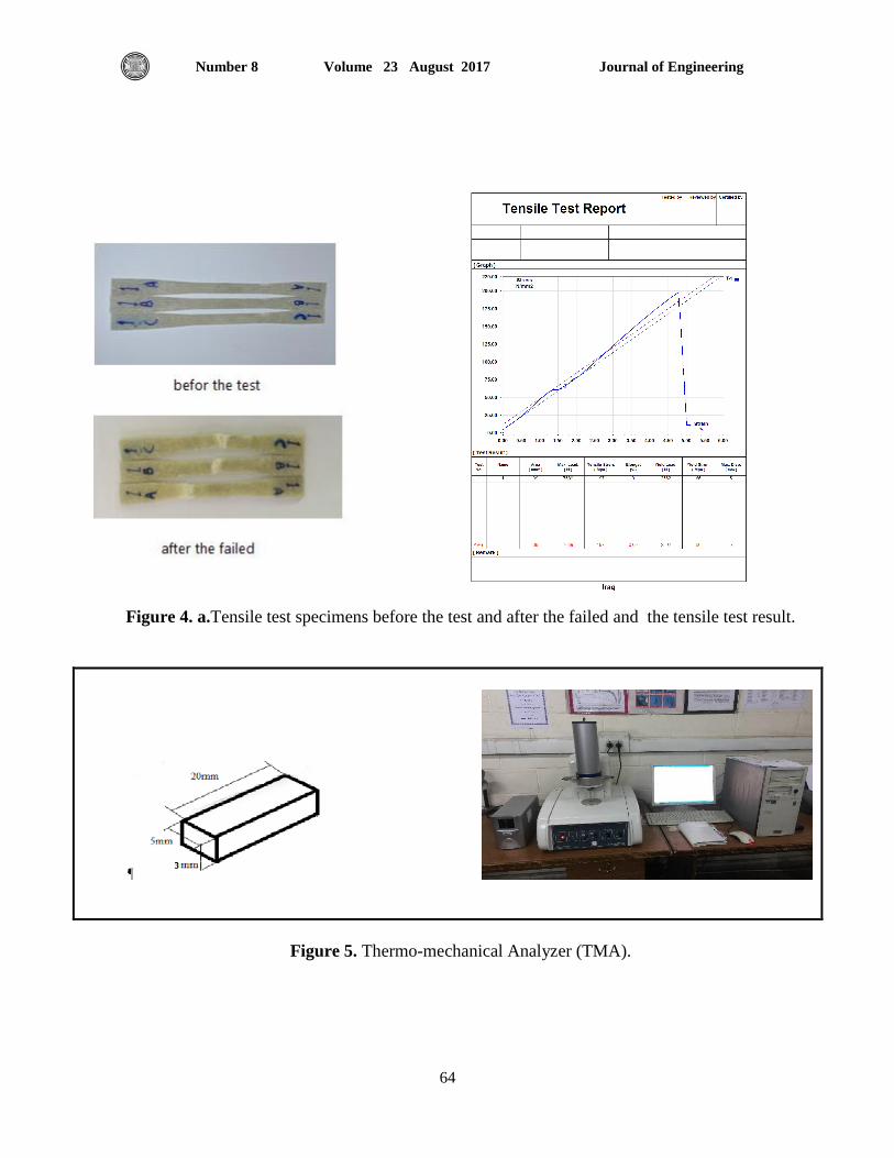
2.3 Tensile Test
According to ASTM D638-03 the samples were cut up from the manufacturing plate; 165 mm
length, 19 mm width, 3mm thickness [ three sample for each sample] as shown in Fig. 3-a This test
is done in Materials Engineering Department / University of Technology. The tensile test machine is
shown in Fig. 3-b. The specimen was put in this machine and then pulled hydraulically with strain
rate (0.5 mm/min). Fig. 4 shows the manufactured tensile test specimens before the test and after the
failed.

Journal of Engineering Volume 23 August 2017 Number 8
59
2.4 Thermo-Mechanical Analyzer (TMA) Test
TMA is a technique used to measure the change in the dimensions of sample (length or volume)
as a function of temperature. There is widely application for this technique to various material such
as polymers, metal, ceramic, glass and fiber etc. It was used in this research to evaluate the Young
Modulus and coefficient of thermal expansion as a function of temperature. The device, the
dimensions of sample and the manufacturing sample are shown in Fig. 5. This test was achieved in
polymer department of Ministry of Science and Technology.
2.5 Thermal Conductivity Analyzer (TCI)
TCI is a device used to measure the thermal conductivity and effusively of materials. It can be
used for various materials such as powder, liquid, solid and pastes and gives the result in a short
time, when compared with other devices. The device, the dimensions of sample and the
manufactured sample are shown in Fig. 6. This test was achieved in polymer department of Ministry
of Science and Technology.
2.6 Bending Test
The aim of this test is to identify the linear behavior of the material under the influence of the
applied load vertically to the surface plane of it. The bending test includes the determining of the
value of the deflection that occurs by the effect of applying the force. The bending structure rig is
consisting of the following parts as shown in Fig. 7.
1. Metal vise is used to fix the models of the rocket fins as a cantilever plate
2. Dial indicator is an instrument used to measure the deflection in the tip of the fin due to
loading. It was fixed by the holder
3. Load cell is a sensor used to create an electrical signal which it's magnitude is proportional to
the applied load.
4. Load cell indicator is used to convert the signal coming back from the load cell into force
signal. The type used in this research displays force in kg unit.
5. Power supply is to provide the device with electric power.
6. Electric stove used to heat the models.
7. Thermos-reader with thermocouple is used to measure the temperature of the samples during
the test.
All instrument used in this test were calibrated in Central Organization for Standardization and
Quality Control. The concentrated force is applied by rotating the screw which is existing on load
cell.
3. NUMERICAL ANALYSIS
The analytical solution of the plate bending is depending on the condition of the plate (geometry,
boundary condition and load configuration). If these conditions are so complicated, the analytical
solution becomes also complicated. In case a complex structure the numerical solution is used to
verify the experimental results. The finite element method is a muscular computational technique in
order to obtain the solution of integral and different equations that increasing in most fields of
science and engineering, Timoshenko, 1959.
The deflection of models of fins is analyzed using finite element method by employment ANSYS

Journal of Engineering Volume 23 August 2017 Number 8
60
program (version 15). The element type used in this research is shell 281 and its geometry is shown
in Fig. 8. ANSYS recommends against using element in triangle form, zero-area elements are not
allowed, zero-thickness elements are not allowed and no slippage is assumed between the element
layers’ shear deflections are included in the element; however, normal to the center plane before
deformation are assumed to remain straight after deformation. Mechanical and thermal properties
were defined to create the numerical model, then meshing the model with appropriate mesh,
applying boundary condition, applying concentrated load, solving and finally plot the deflection for
each model.
4. RESULTS AND DISCUSSION
The results of hyper composite models of rocket fin included the experimental results of
mechanical and thermal properties of these models composed of chopped glass fiber; carbon powder
and polyester resin with different volume fraction are listed in Table 1. Young modulus
experimentally determined from the slope of the stress – strain curve created during tensile test
conducted on a sample of material, the unit of it is (Pa or N/m2). In addition to evaluate the effect of
added carbon powder on the maximum deflection of these models and, study the effect of
temperature on this deflection; the maximum deflection of isotropic hyper composite models of
rocket fins is evaluated experimentally and numerically. A comparison between experimental and
numerical results is done.
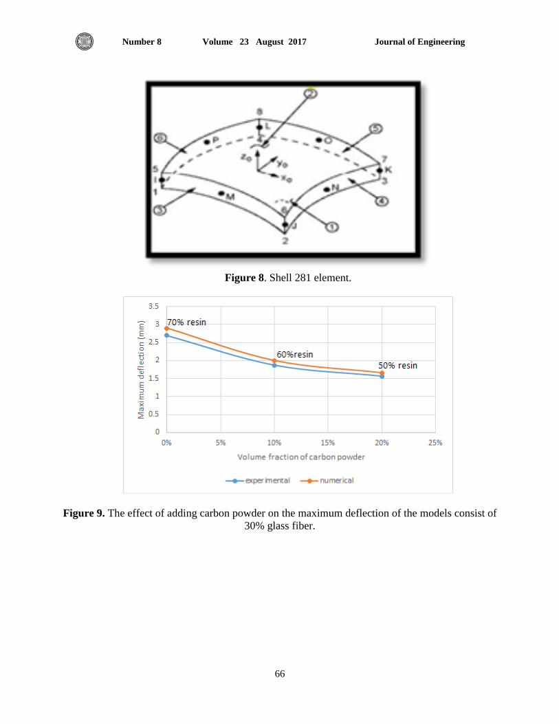
The mechanical and thermal properties of the fins studied are also shown in Table 1. Fig. 9 shows
the effect of adding powder on the maximum deflection of the fins consist of 30% glass fiber. It is
clear that the addition of powder to the composite structure decreases the maximum deflection as a
result of an increase in the Young 's Modulus. The same behavior was occurred for the models that
consist of 20% glass fiber as shown in Fig. 10 but in models consist of 10% volume fraction of glass
fiber; the maximum deflection is increased then decreased as shown in Fig. 11. The effect of
replacing of glass fiber with powder is shown in Fig. 12, 13 and 14 for the models consist of (70, 60
and 50) % of polyester, respectively. These behaviors are happened because of the carbon powder
has high value of tensile strength and flexibility if compared with the glass fiber, as well as
randomly distributed in the polyester material and ease of penetration of matrix material in these
powder and fiber creates a complete interface between the matrix and reinforcement material. But
when the value of volume fraction of powder is increased, it leads to increase the maximum
deflection due to the reduction in the value of Young's Modulus because of the difficulty of
penetration of matrix material in powder and fiber which leads to the weakening of the
interrelationship between matrix and fiber, thus reducing the efficiency of carrying the applied load
on the composite plate. The same behavior was occurred in the ref. (12).
For all models of rocket fins the smallest maximum deflection was occurred in the model no.9
which consist of 50% polyster,30%fiber glass and 20% carbon powder. See Table 1.
The effect of temperature on that maximum deflection is shown in Fig. 15 It is clear that the
maximum deflection was increased in all models when the temperature increasing from room
temperature to 60 °C because the temperature increase leads to a weak bonding strength between
matrix and reinforcing materials thus it becomes soft and it happens a great strain. The minimum
effect of temperature was happened in model no. 8 (40% fiber glass,10% carbon powder and 50%
polyester

Journal of Engineering Volume 23 August 2017 Number 8
61
5. CONCLUSION
The most important conclusions that have been reached by this study are:
1. The addition of powder to the composite structure composed of polyester and glass fiber
leads to the increasing of Young's Modulus (maximum value 6.36 GPa) and decreasing
maximum deflection.
2. The comparison between experimental and numerical investigations showed a good
agreement between the results.
3. Increasing of the value of the maximum deflection is happened due to temperature increase.
4. The minimum effect of temperature was happened in model no. 8 (40% fiber glass,10%
carbon powder and 50% polyester)
5. the smallest maximum deflection was occurred in the model no.9 which consist of 50%
polyster,30%fiber glass and 20% carbon powder.
6. REFERENCES
Abbas, R., A.,2007, The Influence of Temperature on the Mechanical Properties of Hybrid
Composite, Journal of Al-Nahrain University, Vol.10, No.1, PP. 11-23.
Al-alkawi, H., J., Al-Fatall, D., S., and Ali, A., H., 2012, An Experimental Study on Tensile
Modulus and Strength of Metal Matrix Composite Material at Room and Low Temperature,
The Iraqi Journal for Mechanical and Material Engineering, Vol.15, No.2, PP 1935-1947.
Basim, 2014, Effect of industrial powder on mechanical properties of glass fiber reinforced
epoxy composite, Iraqi Journal of Physics, Vol.12, No.25, PP. 8-24.
Ibrahim, 2011, Flexural Properties of Glass and Graphite Particles Polymer Composite,
IBN Journal for Pure &Appl. SCI, Vol.24, No.1, 34-43.
Mohammed, F., and Smait, D., 2012, Mechanical and Tribological behavior of Glass-
polyester Composite System Under Graphite Filler Content, Eng. & Tech. Journal, Vol. 30,
No. 4, PP. 672-683.
Mohammed, R., 2013, Study the Effect of Glass Fibers on Mechanical Properties of Epoxy
Composites, Eng. & Tech. Journal, Vol. 31, No.5, PP.653-659.
Mutsuyoshil, H., Aravinthan, T., 2010, Development of New Hybrid Composite Material
Consisting of Carbon and Glass Fibers, Saitama University, INC, Japan.
Sakthivel, A. R., Rajendran, D., 2014, Experimental Investigation and Analysis of a
Mechanical properties of Hybrid Polymer Composite Plate, IJETT, Vol.9, N.8.
Thanon, H., 2013, Effect of Temperature on Mechanical and Thermal Properties of
Polyester Matrix Reinforced by Ordinary Glass Powder, Al-Rafidain Journal of Science,
Vol.24, No.3, PP.75-85 ص
Timoshenko, S., 1959, Theory of Plates and Shells, second edition.
Putic, S., Stamenovic, M., and Bajceta, B., 2007, The influence of high and low
temperature on the impact properties of glass-epoxy composites, J. Serb. Chem. Soc.
Vol.27, No.7, PP. 713-813.

Journal of Engineering Volume 23 August 2017 Number 8
62
, دساست اخىاص اىاىت ىاد خشاوبت هدت راث اساط 0505"سهات عس ,واظ طش و لحطا عذا ",
4,اعذد 02بىش مىاة بالااف ودلائك" دت اهذست واخىىىخا ,ادذ
Table 1. mechanical and thermal properties of the models.
Model
no.
Volume
fraction of
polyester %
Volume
fraction of
fiber %
Volume
fraction of
powder %
E
(GPa)
K
(W/m.C)
α
(10-6
)/C
Maximum
Deflection
(mm)
1 70 30 - 3.7 0.296 17.23 2.7
2 70 25 5 4.65 0.341 18 2.12
3 70 20 10 4.187 0.293 21.89 2.36
4 70 10 20 2.55 0.463 22 3.94
5 60 30 10 5.26 0.396 23.45 1.87
6 60 20 20 3.25 0.586 26.65 3
7 60 10 30 1.73 0.433 27.1 6.04
8 50 40 10 5.53 0.442 12.84 1.84
9 50 30 20 6.36 0.491 16.35 1.56
10 50 20 30 3.06 0.677 19.34 3.15
11 50 10 40 2.6 0.616 21.32 4
Figure 1. The mold.

Journal of Engineering Volume 23 August 2017 Number 8
63
Figure 2. Models of rocket fins.
Figure 3. (a) dimensions of tensile test specimen (ASTM D 638-03). (b) tensile test machine.
a b
Journal of Engineering Volume 23 August 2017 Number 8
64
Figure 4. a.Tensile test specimens before the test and after the failed and the tensile test result.
Figure 5. Thermo-mechanical Analyzer (TMA).

Journal of Engineering Volume 23 August 2017 Number 8
65
Thickness 3mm TCI device.
Figure 6. Thermo-conductivity Analyzer test (TCI).
Figure 7. The test rig of bending test.
Metal vise
Journal of Engineering Volume 23 August 2017 Number 8
66
Figure 8. Shell 281 element.
Figure 9. The effect of adding carbon powder on the maximum deflection of the models consist of
30% glass fiber.

Journal of Engineering Volume 23 August 2017 Number 8
67
Figure 10. The effect of adding carbon powder on the maximum deflection of the models consist of
20% glass fiber.
Figure 11. The effect of adding carbon powder on the maximum deflection of the models
consist of 10% glass fiber.

Journal of Engineering Volume 23 August 2017 Number 8
68
Figure 12. The effect of replace the glass fiber with carbon powder on the maximum deflection
of the models consist of 70% polyester.
Figure 13. The effect of replacing fiber with powder on the maximum deflection of the models
consist of 60% polyester.

Journal of Engineering Volume 23 August 2017 Number 8
69
Figure 14. The effect of replace fiber with powder on the maximum deflection of the models
consist of 50% polyester.
Figure 15. The effect of the temperature on the maximum deflection for all models.
0
2
4
6
8
10
12
14
20 25 30 35 40 45 50 55 60 65
Max
imu
m d
efle
ctio
n (
mm
)
Temperature °C
no.1 no.2 no.3 no.4 no.5 no.6
no.7 no.8 no.9 no.10 no.11