experimental evaluation of shape factor of axis...
TRANSCRIPT

1
Experimental Evaluation of Shape Factor of Axis Symmetric Sunken
Structures
Dhananjay R. Mishra
Department of Mechanical Engineering, Jaypee University of Engineering & Technology,
A.B. Road, Guna-473226, Madhya Pradesh (India)
Abstract:
This paper presents the dependence of a shape factor for the fully sunken axis
symmetrical structures (viz. cubical, square prismatic, pyramidal, and cylindrical)
corresponding to the depth and their orientation. Experimental evaluations of the shape factor
on reduce scale models are carried out in laboratory using thermal simulation method for
different sets of conditions. The method has been used to determine shape factor, which can
be used to determine heat loss from ground to structure or structure to groud fully sunken
with the different orientation. Maximum and minimum value of shape factor for set-I and II
condition are recoded as 90.18 and 9.93 respectively. In set –III it will varies from 16.49 to
35.28. At 2D L shape factor of set-VI leads by 17.26 % as compared to set VII. Where as
set- IX leads by 33.47% as compaired to set VIII. It would help for designing building
structure of fully buried nature for creating thermal comfort.
Keywords: Thermal simulation; heat transfer; buried structure.
Symbols
D Depth of model below earth surface, m
F Shape factor of cubical structure placed about its lateral surface on horizontal plane,
set I condition (dimensionless)
'F Shape factor of cubical structure placed about its edge and lateral surfaces are equally
inclined to horizontal surface, set II condition (dimensionless)
''F Shape factor of cubical placed on horizontal surface about its corner in such way so
that all edges are equally inclined to it, set III condition (dimensionless)
IVF Shape factor of square prismatic structure placed about its lateral surface in Set IV
condition (dimensionless)
VF Shape factor of square prismatic structure placed on horizontal plane about its one of
the edge of the lateral surface in Set V condition (dimensionless)
VIF Shape factor triangular pyramid structure placed about its base on horizontal plane, set
VI condition (dimensionless)
Corresponding Author, mobile number: +91 9893808251,
E-mail address: [email protected]; [email protected] (Dhananjay R. Mishra).

2
VIIF Shape factor square pyramid structure placed about its base on horizontal plane, set VI
condition (dimensionless)
VIIIF Shape factor of cylindrical structure placed about its end surface on horizontal plane,
set VIII condition (dimensionless)
IXF Shape factor of cylindrical structure placed about its lateral surface on horizontal plane,
set IX condition (dimensionless)
I Current on heating bulb or element, A
K Thermal conductivity of ground or sand, W m C
L Characteristic length of object, m
Q
Rate of heat loss from building to ground, W
r Radius of the sphere, m
sT Temperature of surface of building or model,
C
gT Temperature of the earth surface, C
V Voltage across the heating element or bulb, V
1cosh D R
1. Introduction
An evaluation of heat transfer between the ground and an earth coupled structure is
essential for a rational thermal design of the latter for creating human comfort. The solution of
the corresponding three dimensional Fourier equation of thermal conduction with relevant
boundary conditions is in general very difficult if at all possible; the analytical solutions of
highly symmetrical structure can be obtained only for structures with high symmetry like a
sphere or an infinite cylinder with horizontal axis [1,2]. Evaluation of the heat transfer through
the building structure to surrounding ground is needed three-dimensional heat conduction
relation with the appropriate boundary conditions for the computation of heat transfer between
structure and earth surface. Numerical methods for few axis symmetrical (like cylinder and
sphere) sunken structures are available but it needs large computational time [3,4]. Effect of
different earth surface treatment of surrounding surface for heating and cooling of earth-
integrated building structures are reported by Sodha and his associates [5,6]. The theoretical
basis for dynamic simulation (arbiter time variation) heat transfer between ground and
structure using electrical simulation for fully buried structures of periodic nature has been
reported by Sodha. These suggested methods are needed to reduce scale models for simulation
purpose which can further scale up for bigger realistic situation [7]. Mishra et al.[8] have
been validated the basis for the experimental simulation of heat transfer between ground and
structure proposed by Sodha [9,10]. Geometical optimization of heat storage unit using shape
factor of structure has been reported by Solé et al. [11]. Experimental evaluation of heat
transfer between full scale fully or partially buried structures and ground is not feasible on

3
account of the corresponding high cost; moreover, the large variations in size and shape of the
structure make a specific experiment to have little relevance with the real problem. wall-to-
excavation shape factor concept use for the preliminary design of deep cement mixing walls
for identification of cause of excavation failure has been reported by Waichita et al. [12].
Influence of dam geometry and satellment of rock fill dams based on shape fator unding finite
element analysis has been reported by Sukkarak et al. [13]. Dependence of berming;
corresponding dependence on the slope of berming has been reported by Sodha and Mishra
[14]. CFD simulation and analysis of the temperature distribution within the green houe, solar
heat gain and heat loss using sing shape factor has been reported by Tong et al. [15]. Shape
fators of three different desgine and its optimization using RSM and validation with P test for
the steady state heat transfer between swimming pool water and surrounding ground has been
reported by Somwanshi et al. [16]. Utilistion of shape factor of device/ equipement for the
analysis of heat transfer from surface to ambient or ambient to surface have been reported by
various researchers [17–22]. Evaluation of heat transfer from fully sunken structure to the
surrounding ground or surrounding ground to sunken structure is a comples phenomena.
Although fully sunken building structure is a popular method for degine of bunkers and
partially sunken for heigh rise buildings, one has to adopt approximation of doubtful merits for
the evaluation of heat transfer from fully sunken structure to the surrounding ground or
surrounding ground to sunken structure. From the brief account neumerical simulation is
difficult and highly time consuming for realistic cases. This brigs us possibility of thermal
simulation experiment, which would enables one to evaluate heat transfer from fully sunken
structures to the ground on resuce scale structure in small time duration. The shape factor of
fully buried axis symmetrical structures using thermal simulation method is presented in this
paper. Dependence of shape factor corresponding to depth and orientation are reported in this
paper.
2. Experimental setup
A reduced scale model i.e. dry fine silica sand in a wooden box of a dimensions 1×1×1 m
(Fig.1a) treated as a semi-infinite medium. Hollow sphere made of the copper material having
98% purity (chosen on account of large thermal conductivity) is energized with the
incandescent lamp used for evaluation of the thermal conductivity of silica sand. A constant
DC power source of 24V ,
The symmetrical standard structures are modeled (made of a copper sheet of thickness 1.5
mm) viz. Hollow copper sphere for determination of the thermal conductivity of the silica
sand.
Fig.1a
An incandescent lamp is placed inside the box in all the cases and the steady state
(normally after 8–10 h) difference of temperature between the surface of the structures and the
simulated earth surface was noted (by a temperature indicator DTI-039T) corresponding to
eight values of the power consumption (product of the current and potential difference) by the
lamp.
Fig.1b

4
Actual photograph and schematic arrangement of the experimental setup are illustrated in
Figs. 1a and 1b respectively. Shape factor is a parameter used for the prediction of the thermal
behavior of sunken structures of symmetrical in nature with different depth and orientation.
Figs.2 and 3 represents a photograph of the cubical structure of 10 side and square prism of
base side 5 and axis 10 long. Figs. 4a and 4b represent the photograph of the triangular and
square pyramid of base side 5cm and axis 10 cm long. A photograph of the cylindrical
structure of 5 base diameter and 10 axis length is shown in Fig. 5. The rate of heat transfer
from a sphere of a radius at a depth of earth surface and shape factor of the hollow sphere of
0.015 radii has been used as a simulation structure[13,14]. As heat transfer through the
structure can be evaluated with the Eq.1.
' s gQ F rK D r T T
(1)
where, 3 51 sinh sinh
' 4 1 cosh 1 cosh3 1 cosh5 ...2 sinh3 sinh5
F e e e
(2)
Rearranging Eq.1 we can get
' s gK Q rF D r T T
(3)
A different set of experimentations are carried out for the determination of the shape factor of
structures for their different orientations.
Fig.2
Fig.3
Fig.4a
Fig.4b
Fig.5
3. Observation, result and discussion
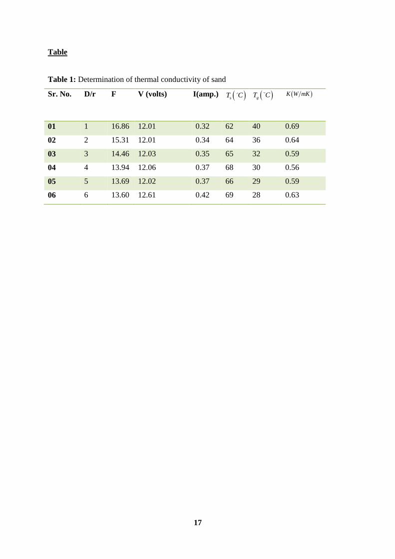
The thermal conductivity K of sand is in general dependent on the temperature; however,
within the range of parameters of interest, the variation is less than the accuracy of
determination of K . In any case the experimental simulation does not allow for the
temperature-dependent thermal conductivity. The thermal conductivity of simulating media
(sand) has been experimentally evaluated using thermal simulation method and tabulated in
Table 1.
Table 1
On the basis of six continuous observations and using Eq.2, it has been recorded as 0.07
0.060.62 W mK Variation of the shape factor of a hollow copper cube of 10cm long side
with response to different depth and orientations of the structure are reported with the help of a
different set of the condition in

5
Fig.6. Three different sets of conditions for cubical structure is used to determination of
the shape factor, maximum value of shape factor is recorded 90.18 at D L ratio 2 for set I of
a cubical structure place on horizontal surface and minimum value of 'F is 9.93 is recorded
for set II cubical structure placed in HP about its one of the corner and its edges are equally
inclined to HP at D L ratio 10. ''F is varied from 35.28 to 16.49 while the experimentation
for set III when the cubical structure is placed on edge and its lateral surfaces are equally
inclined to HP and end surfaces are perpendicular to the HP.
Fig.6
Shape factor cubical structure for Set I, II and III conditions one can get from Eq. 4,6 and 8
respectively :
2
0.1971 5.0624 48.927F D L D L (4)
2 0.99R (5)
2
' 0.1866 3.4513 26.168F D L D L (6)
2 0.9959R (7)
2
'' 0.3552 6.469 46.11F D L D L (8)
2 0.981R
The shape factor of the square prism of base side 5 cm and axis 10 cm long set IV and V
square prismatic structure placed about its lateral surface and edge of lateral surface and axis
kept parallel to the horizontal surface respectively. Experimental result for the evaluation of
shape factor is shown in Fig. 7.
Fig.7
Experimental results for the fully sunken structure at different D L ratio and orientation
are shown in Fig.8. Maximum 30.32 value of shape factor for IV condition is recorded while
experimentation at a D L ratio of 2 and a minimum value of shape factor 8.73 at a D L ratio
10 in set V condition. Shape factor at D L ratio 10 for set IV is 15.32% higher as compared to
set V. It indicates maximum comfort within the underground structure of square prismatic
structure in the fully buried case with this relation and orientation. Eq. 9 and 10 can be utlised
for the theoretical evaluation of shape factor for the IV and V set of conditions respectively.
2
0.058 3.2779 37.086IVF D L D L (09)
2 0.9924R (10)
2
0.1204 4.073 37.24VF D L D L (11)
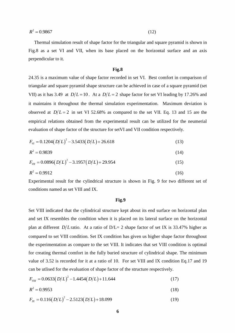
6
2 0.9867R (12)
Thermal simulation result of shape factor for the triangular and square pyramid is shown in
Fig.8 as a set VI and VII, when its base placed on the horizontal surface and an axis
perpendicular to it.
Fig.8
24.35 is a maximum value of shape factor recorded in set VI. Best comfort in comparison of
triangular and square pyramid shape structure can be achieved in case of a square pyramid (set
VII) as it has 3.49 at 10D L . At a 2D L shape factor for set VI leading by 17.26% and
it maintains it throughout the thermal simulation experimentation. Maximum deviation is
observed at 2D L in set VI 52.68% as compared to the set VII. Eq. 13 and 15 are the
empirical relations obtained from the experimental result can be utilized for the neumerial
evaluation of shape factor of the structure for setVI and VII condition respectively.
2
0.1204 3.5433 26.618VIF D L D L (13)
2 0.9839R (14)
2
0.0896 3.1957 29.954VIIF D L D L (15)
2 0.9912R (16)
Experimental result for the cylindrical structure is shown in Fig. 9 for two different set of
conditions named as set VIII and IX.
Fig.9
Set VIII indicated that the cylindrical structure kept about its end surface on horizontal plan
and set IX resembles the condition when it is placed on its lateral surface on the horizontal
plan at different D L ratio. At a ratio of D/L= 2 shape factor of set IX is 33.47% higher as
compared to set VIII condition. Set IX condition has given us higher shape factor throughout
the experimentation as compare to the set VIII. It indicates that set VIII condition is optimal
for creating thermal comfort in the fully buried structure of cylindrical shape. The minimum
value of 3.52 is recorded for it at a ratio of 10. For set VIII and IX condition Eq.17 and 19
can be utlised for the evaluation of shape factor of the structure respectively.
2
0.0633 1.4454 11.644VIIIF D L D L (17)
2 0.9953R (18)
2
0.116 2.5123 18.099IXF D L D L (19)

7
2 0.9926R (20)
4. Conclusion
The shape factor of fully buried axis symmetric structure depends on D/L ratio. It is an
essential input parameter for the evaluation of thermal performance of fully sunken structure.
By knowing shape factor of the fully buried structure heat transfer from ground to structure
or structure to ground easily evaluated. It would help for designing building structure of fully
buried nature for creating thermal comfort.
REFERENCES
[1] Shelton, J.A.Y. "Underground storage of heat in solar heating systems", Solar Energy,
17, pp. 137–143(1975).
[2] Mishra, D.R. and Tiwari, A.K. "Sunken effect on building structures", I-Manager's
Journal on Mechanical Engineering, 2, pp. 41–45 (2008).
[3] Givoni, B. "Underground longterm storage of solar energy—An overview", Solar
Energy, 19, pp. 617–623 (1977).
[4] Patil, K., Srivastava, V. and Baqersad, J. "A multi-view optical technique to obtain
mode shapes of structures", Measurement: Journal of the International Measurement
Confederation, 122, pp. 358–367 (2018).
[5] Deshmukh, M.K., Sodha, M.S. and Sawhney R.L. "Effect of depth of sinking on
thermal performance of partially underground building", International Journal of
Energy Research, 15, pp. 391–403 (1991).
[6] Martinopoulos, G. "Solar Energy in Buildings: Reference Module in Earth Systems
and Environmental Sciences", 2016.
[7] Sodha, M.S., Sawhney, R.L. and Jayashankar, B.C. "Estimation of steady state ground
losses from earth coupled structures by simulation", International Journal of Energy
Research, 14, pp. 563–571 (1990).
[8] Mishra, D.R., Sodha, M.S. and Tiwari, A.K. "Validation of the basis of experimental
simulation of heat transfer between a building and surrounding earth", SESI Journal ,
21, pp. 36–48 (2013).
[9] Sodha, M.S. "Simulation of periodic heat transfer between ground and underground
structures", International Journal of Energy Research, 25, pp. 689–693 (2001).
[10] Sodha, M.S. "Simulation of dynamic heat transfer between ground and underground
structures", International Journal of Energy Research, 25, pp. 1391–1394 (2001).

8
[11] Solé, A., Falcoz, Q., Cabeza, L.F. and Neveu, P. "Geometry optimization of a heat
storage system for concentrated solar power plants (CSP)", Renewable Energy, 123 ,
pp. e95 (2018).
[12] Waichita, S., Jongpradist, P. and Jamsawang, P. "Characterization of deep cement
mixing wall behavior using wall-to-excavation shape factor", Tunnelling and
Underground Space Technology, 83 pp. 243–253 (2019).
[13] Sukkarak, R., Jongpradist, P. and Pramthawee, P. "A modified valley shape factor for
the estimation of rockfill dam settlement”, Computers and Geotechnics, 108, pp. 244–
256 (2019).
[14] Sodha, M.S. and Mishra, D.R. "Shape factor for bermed wall", Heat Mass Transf. Und
Stoffuebertragung, 47, pp. 1143–1146 (2011).
[15] Tong, G., Christopher, D.M. and Zhang G. "New insights on span selection for
Chinese solar greenhouses using CFD analyses", Computers and Electronics in
Agriculture, 149, pp. 3-15 (2017).
[16] Somwanshi, A., Dixit, A. and Tiwari, A.K. "Shape factor for steady state heat transfer
between swimming pool water and wsurrounding ground", Fundamentals of
Renewable Energy and Applications, 4, pp. 2–5 (2013).
[17] El-samadony, Y.A.F.A.F., El-maghlany, W.M. and Kabeel, A.E.E. Influence of glass
cover inclination angle on radiation heat transfer rate within stepped solar still, DES.
384, pp. 68–77 (2016).
[18] Ruivo, C.R. and Vaz, D.C. "Prediction of the heat gain of external walls: An
innovative approach for full-featured excitations based on the simplified method of
Mackey-and-Wright", Applied Energy, 155, pp. 378–392 (2015).
[19] Amarasinghe Vithanage D., Devižis, A., Abramavičius, V., Infahsaeng, Y.,
Abramavičius, D., MacKenzie, R.C.I., Keivanidis, P.E., Yartsev, A., Hertel, D. ,
Nelson, J., Sundström, V. and Gulbinas, V. "Visualizing charge separation in bulk
heterojunction organic solar cells", Nature communications, 4, pp. 23-34 (2013).
[20] Boulton, C., Dedekorkut-Howes, A. and Byrne, J. "Factors shaping urban greenspace
provision: A systematic review of the literature", Landscape and Urban Planning, 178,
pp. 82–101 (2018).
[21] Kiwan, S. and Khammash, A.L. "Investigations into the spiral distribution of the
heliostat field in solar central tower system", Solar Energy, 164, pp. 25–37 (2018).
[22] Chel, A., Tiwari, G.N. and Singh, H.N. "A modified model for estimation of daylight
factor for skylight integrated with dome roof structure of mud-house in New Delhi

9
(India)", Applied Energy, 87, pp. 3037–3050 (2010).
Figure captions
Fig. 1a: Actual photograph of the experimental setup
Fig. 1b: Schematic diagram for determining thermal conductivity of sand
Fig. 2: Photograph of cubical structure
Fig. 3: Photograph of square prismatic structure
Fig. 4a: Photograph of triangular pyramid structure model
Fig. 4b: Photograph of square pyramid structure model
Fig. 5: Photograph of cylindrical model
Fig. 6: Variation of shape factor with respect to different depth for Set I, II and III of a cubical
structure
Fig. 7: Variation of shape factor with the depth of square prism.
Fig. 8: Variation of shape factor with the depth of triangular (set VI) and square (set VII)
pyramids.
Fig. 9: Variation of shape factor with the depth of cylinder placed on its end surface (set VIII)
and placed on its lateral surface (set IX).

10
Table Caption
Table 1: Determination of thermal conductivity of sand

11
Figures
Fig.1a: Actual photograph of the experimental setup
Fig.1b: Schematic diagram for determining thermal conductivity of sand

12
Fig.2: Photograph of cubical structure
Fig.3: Photograph of square prismatic structure

13
Fig.4a: Photograph of triangular pyramid structure model
Fig.4b: Photograph of square pyramid structure model

14
Fig.5: Photograph of cylindrical model
Fig.6: Variation of shape factor with respect to different depth for Set I, II and III of a cubical
structure

15
Fig.7: Variation of shape factor with the depth of square prism.
Fig.8: Variation of shape factor with the depth of triangular (set VI) and square (set VII)
pyramids.

16
Fig.9: Variation of shape factor with the depth of cylinder placed on its end surface (set
VIII) and placed on its lateral surface (set IX).
17
Table
Table 1: Determination of thermal conductivity of sand
Sr. No. D/r F V (volts) I(amp.) sT C
gT C K W mK
01 1 16.86 12.01 0.32 62 40 0.69
02 2 15.31 12.01 0.34 64 36 0.64
03 3 14.46 12.03 0.35 65 32 0.59
04 4 13.94 12.06 0.37 68 30 0.56
05 5 13.69 12.02 0.37 66 29 0.59
06 6 13.60 12.61 0.42 69 28 0.63

18
Dr. Dhananjay R. Mishra is an Assistant Professor Senior (SG) in Department of
Mechanical Engineering at Jaypee University of Engineering & Technology, Guna. He
received his Ph.D. in Mechanical Engineering from National Institute of Technology Raipur,
India in 2016. He has published more than 50 research papers in reputed peer reviewed
national and international journal. He is supervising four students, leading to the Ph.D. degree
from Jaypee University of Engineering & Technology and National Institute of Technology
Raipur. He is associated as an editor to ‘International Journal of Thermodynamics &
Catalysis’ , associate editor of International ‘Journal of Applied Research’ and editorial board
member of nine other peer reviewed international Journals. He has an association with the
Suprabha Industries Ltd., Lucknow, as an Assistant Production Manager, During 2002 -2004,
as a Lecturer in Mechanical Engineering Department, Rungta College of Engineering and
Technology, Bhilai, C.G. (During Sept. 2005 to March 2006), as a Lecturer in Mechanical
Engineering Department, Shri Shankaracharya College of Engineering and Technology,
Bhilai, C.G.(During March 2006 to July 2007) as an Assistant Professor in Department of
Mechanical Engineering at Disha Institute of Management & Technology and also carried out
responsibility of Academic Administrator (July,2007 to July,2012). Since July 2012, he is
associated as an Assistant Professor (SG) in Mechanical Engineering Department, JUET,
Guna (M.P.). He has established State Level Energy Park at DIMAT funded by MNRE
through Nodal agency CREDA. He has also completed a research project titled as
“Determination of the parameters affecting heat transfer between ground and fully or partially
underground structures” sponsored by Chhattisgarh Council of Science and Technology at
Disha Institute of Management & Technology, Chhattisgarh.