experimental study of a 100-kw class applied-field mpd...
TRANSCRIPT

The 32nd International Electric Propulsion Conference, Wiesbaden, Germany
September 11 – 15, 2011
1
Experimental Study of a 100-kW class Applied-Field MPD Thruster
IEPC-2011-110
Presented at the 32nd International Electric Propulsion Conference, Wiesbaden • Germany
September 11 – 15, 2011
R. Albertoni1, P. Rossetti2, F. Paganucci3, M. Andrenucci4 Alta SpA, Via A. Gherardesca 5, 56121, Ospedaletto, Pisa, Italy
M. Zuin5, E. Martinez6, R. Cavazzana7 Consorzio RFX, Corso Stati Uniti 4, 53127, Padova, Italy
Abstract: A new 100 kW, gas-fed, applied field magneto-plasma-dynamic thruster has been designed, manufactured and preliminarily tested at Alta. The thruster configuration has been selected on the basis of the most efficient models from the literature, with multichannel hollow cathode and flared anode. The thruster has been tested in quasi-steady conditions with pulse duration of 500 ms at currents up to 2700 A, with argon mass flow rates ranging from 60 to 120 mg/s and applied magnetic field from 50 to 120 mT. By using a new thrust balance developed at Alta, the thrust has been measured in real time during any pulse. The thruster has been also conceived to test a plasma instability control technique, based on the application of a conductive shell around the anode. In order to characterize the magnetic field topology during the discharge with and without the shell, an array of non-intrusive high frequency magnetic field probes has been integrated in the anode body.
I. Introduction he experimental investigation of gas-fed, applied field MPD thrusters (AF-MPDTs), operating in a steady state mode at power higher than 100 kW and mass flow rate ranging from tens to hundreds of mg/s, is often limited
by the availability of vacuum facilities capable of maintaining a back pressure under a certain limit value (at least in the 10-4 mbar range) during firing. As matter of fact, it was demonstrated that at higher values, the back pressure can significantly affect the thruster performance, jeopardizing the reliability of the experiments1,2. So far, tests carried out at Alta on AF-MPDTs have been performed in relatively small vacuum chambers (inner volume up to 10 m3), in a pulsed, quasi-steady mode, with the electrical power supplied by a pulse forming network for shots from 1 to 5 ms long. In these experiments, the typical test sequence includes vacuum chamber evacuation till about 10-5 mbar before each shot, by means of diffusion or turbo-molecular pumps. Hence, the requested limit of back pressure during firing is guaranteed by the plant vacuum inertia, i.e. by its volume. With a volume of about 200 m3, Alta’s IV-10 vacuum facility allows AF-MPDTs to be tested at a back pressure within the limits with shots up to 1 s long. Although the shot length remain too short to simulate the thermal condition of a continuous operation, it is long enough to allow a direct thrust measurements, instead of a total impulse measurement per shot, by means of a ballistic thrust stand, as made so far. The following paragraphs
1 PhD Candidate, Aerospace Engineering Dept., University of Pisa, [email protected]. 2 Project Manager, Alta SpA, [email protected]. 3 Associate Professor, Aerospace Engineering Dept., University of Pisa, [email protected]. 4 Full Professor, Aerospace Engineering Dept., University of Pisa, [email protected]. 5 Researcher, Consorzio RFX, [email protected]. 6 Researcher, Consorzio RFX, [email protected]. 7 Researcher, Consorzio RFX, [email protected].
T

The 32nd International Electric Propulsion Conference, Wiesbaden, Germany
September 11 – 15, 2011
2
describe the activities carried out in the last months at Alta to set-up a new AF-MPDT and the relevant test equipment to perform long shots (500 ms) in IV-10. A thrust stand has been designed and manufactured to measure instantaneous thrust during the shot. Moreover, the thruster has been conceived to continue the experimental studies on plasma instabilities and their control, underwent since 2000 in collaboration with RFX3-5. The thruster can be equipped with metallic shells surrounding the anode, to assess a passive method of reducing the growth rate of large scale MHD instabilities. An array of four three-axis magnetic probes inserted in the anode allows MHD instabilities to be detected and characterized. The paper also describes the results of a first series of tests, mainly aimed at demonstrating the effectiveness and the reliability of the entire set-up.
II. Experimental setup
A. Thruster description A new quasi-steady MPD thruster was designed and manufactured as shown in Figure 2. The thruster was
developed after the russian “Ageyev-type” high current plasma accelerator with a multi-channel hollow cathode (McHc) and flared anode with anode-to-cathode radius ratio of about 3.
The anode, made of copper, consists of two segments to allow the mounting of the instability control system around the divergent part. The use of copper is justify by negligible thermal concerns when operating in pulsed regime and by the need of weight reduction. The thruster anode has a 95 mm inner diameter and enlarges to the exit section to approximately 130 mm. The inside of the McHc is tightly packed with 330 pure tungsten rods of 3 mm diameter and 40 mm length. The open cross section after filling is about 2.2 cm2 leading to a porosity of about 17%. The main cathode tube is a 180 mm long stainless steel cylinder with 2 mm thick wall and 40 mm inner diameter. It consists of two cylindrical parts allowing cathode length variations by changing the rear part.
Figure 2: MPDT during assembly (left) and into the testing facility (right)
The propellant is injected through the multi-channel hollow cathode. At the gas inlet, the cathode is provided with a flange for the connection to the feeding system through a convergent-divergent nozzle with a calibrated throat of 1.6 mm in diameter. In order to guarantee an external magnetic field of at least 80 mT at the cathode tip, a coaxial solenoid with 430 turns and a current of about 40 A is used. The solenoid was especially design to minimize the total mass and the thermal power losses at the nominal magnetic field of 80 mT. The thruster was operated in quasi-steady pulsed mode with discharges of 500 ms length. The peak power levels ranged from 25 kW (50 V, 500 A) up to 170 kW (100 V, 1700 A) with mass flow rate of argon between 60 mg/s and 120 mg/s. Figure 1 shows a firing shot at 120 mg/s, 50 mT and approximately 2200 A.
Figure 1: MPD thruster firing

The 32nd International Electric Propulsion Conference, Wiesbaden, Germany
September 11 – 15, 2011
3
A. Testing facility The MPD thruster was operated in Alta IV10 vacuum chamber. The chamber consists of a 6 m dia. x 6 m long
cylindrical stainless steel body with two ellipsoidal end caps featuring a total length of 10 m and an internal volume of about 200 m3. The material of the vessel (AISI 316L) is diamagnetic with a relative permeability lower than 1.08. The facility is fully lined internally with LN2 cooled shrouds in order to improve the pumping speed. The pumping system currently installed consists of 4 dry and completely oil free stages and 24 cold heads capable of a ultimate vacuum level of 2e-9 mbar. The MPDT was mounted on a supporting structure connected to the fixed cap and aligned with the beam target. The maximum pressure during the gas pulse was 1e-5 mbar as measured by 3 Leybold-Inficon ITR90 Pirani/Bayard-Alpert sensors.
B. Gas feeding system The scheme of the propellant feeding system is shown in Figure 3. The gas system consists of a 8.5 L main
reservoir pre-filled with argon to the desired pressure (225-380 mbar) prior to each shot corresponding to mass flow rates between 60 mg/s and 120 mg/s, as determined during the system calibration. The main reservoir was positioned inside the vacuum chamber in order to prevent contamination by the air, being the pressure of interest below 1 atm. Quasi-steady operation during 500 ms gas pulse was obtained by ensuring that the sonic orifice was as close as possible to the upstream entrance of the cathode, see Figure 5. The propellant was injected through the cathode by means of a fast acting solenoid valve. Prior the tests, mass flow rate and delay time have been measured with an uncertainty within 5% of the measurement by means of the calibration procedure described in a previous paper6.
Figure 3: Schematic of the propellant feeding system
C. Electrical feeding system The electrical circuit is shown in Figure 4. The most important element is the bank of 4 Maxwell Technologies
BMOD0165 super-capacitors (SCs) in series, 165 F and 48 V each, which provide the required quasi-steady current pulse 500 ms long to the thruster. Prior to each firing, a dedicated power supply charge the SCs to the voltage value corresponding to the desired discharge current. The relationships between the charging voltage and the discharge current was preliminary obtained by numerical simulation and refined by a dedicated test session. Since the maximum charging voltage (190 V) is not enough for the discharge initiation, the same pulse forming network (PFN) used so far for short pulse (1-5 ms) testing has been used as thruster ignitor. The PFN, isolated from the SCs bank via high-voltage, high-current diodes, was in parallel with the main circuit.
to Ar reservoir

The 32nd International Electric Propulsion Conference, Wiesbaden, Germany
September 11 – 15, 2011
4
Figure 4: Schematic of the electrical feeding system
The PFN is composed of a bank of 180 70 μF capacitors and 180 20 μH inductances allowing to store energy at a
rate of 600 J/s from a HVL Series 311-6203 charging unit. The initiation of the gas breakdown is controlled by the closure of a mercury vapor ignitron which establishes a potential difference between the thruster electrodes variable from 0 to 1400 V. A EEI DC power supply having voltage and current ratings of 600 V, 400 A respectively was used to provide the current pulse to the solenoid for the generation of the applied field, see Figure 5. Prior to any firing the EEI PS was set to the desired current level and enabled for output power through its control panel. At the same time the SCs were charged to the desired voltage and, by a manual command, a precise sequence of triggers was activated opening the gas valve and closing the coil circuit along with the PFN ignitron. The circuit also comprises a ballast resistance for discharging the SCs in case of firing abortion.
Figure 5: Typical traces of gas (80 mg/s) and magnetic field (83 mT) pulses

The 32nd International Electric Propulsion Conference, Wiesbaden, Germany
September 11 – 15, 2011
5
D. Thrust balance The thrust balance is a single axis stand, especially designed for present experimental campaign to improve the
full scale and the frequency response of the pre-existing Alta’s thrust stand, used with Hall thrusters. The new thrust stand has a double pendulum configuration, capable of sustaining the thruster weight with a degree of freedom along the principal direction. The sensing element is based on high precision optical strain gages measuring the strain on the flexural elements. The thrust stand is based on a tilting platform to allow the leveling of the thrust stand before the calibration and the thruster operations. An electromagnetic calibrator, generating a reference force when requested, was added to the thrust balance to check the proper response of the stand in vacuum prior to each firing.
Figure 6: MPDT on the thrust stand (left) and schematic of the Alta non-ballistic thrust stand
E. Instability control system and diagnostics It has been theoretically demonstrated that a perfectly conducting shell, sufficiently close to the plasma column,
can suppress m=1/n=1 current-driven internal kinks and completely avoid all external modes, i.e. modes resonant externally to the plasma column itself7,8. In practice, however, as a real shell will have finite resistivity, ideal MHD theory shows that the growth time of kink modes, is simply slowed down to the time scale of the resistive shell w, usually of the order of tens of milliseconds9. In practice the kink instability is branched into the so-called resistive wall mode10 (RWM). Once the ideal mode is converted into a RWM mode exhibiting a sufficiently slow growth rate, various additional approaches could be proposed to totally suppress or control mode amplitude. In particular, magnetic feedback stabilization11,12 and/or induced plasma rotation13,14, which have proven to be successful in many fusion devices, seem to constitute promising alternatives for plasma thrusters as well. On some magnetic fusion devices it has been discovered that both magnetic feedback and rotation stabilization successfully operate in synergetic manner to reduce mode amplitude. Bondeson and Ward15 showed that modes can be wall stabilized in the presence of rotation, provided the rotation frequency exceeds a critical value, typically w
-1. In practice, stability requires that the plasma rotation be sufficiently rapid (typically at least 10 to 40% of the ion sound speed) and that the resistive wall be located at a radius rw, that lies within a range r< rw <rc,, bounded from above by the critical radius, rc, at which a perfectly conducting wall would stabilize the kink, and bounded from below by some other radius, r, whose value depends on the plasma rotation frequency. In this respect, new experiments on MPD thrusters to study the effect of a conducting shell surrounding plasma column are needed. Different geometries, shapes and thickness of the shell should be tested, along with different shell proximity to the plasma. In the frame of the present test campaign the effect of the presence of a conducting shell, without significantly modifying the usual geometry of the MPD thrusters will be verified. The shell is positioned coaxially around the anode and electrically connected with the copper structure. In particular two shells, made of different materials and wall thickness, will be tested.

The 32nd International Electric Propulsion Conference, Wiesbaden, Germany
September 11 – 15, 2011
6
The idea is to obtain two shells characterized by a perpendicular magnetic field penetration time w sufficiently distant one from the other to possibly distinguish with some clarity the different effects on the plasma. The first shell is made of aluminum (m) 30 mm thick, which gives a penetration time of the order of 25 ms. The total value of the shell penetration time is thus approximately given by the sum of this value and the penetration time of the copper anode, which is about 2 ms. The effect of this shell will be compared to that produced by the second one which, in combination with the copper anode, should have a w shorter than the discharge duration using the PFN only, i.e 5 ms. In order to obtain an MPD thruster of equivalent mass, the second shell is made in stainless steel (m) with a thickness of 10 mm. The penetration time of the wall in this case would be mostly determined by that of the copper anode, being of the order of 2.3 ms. The diagnostic set-up for plasma fluctuation is made of a system of 4 magnetic probes, each constituted of three coils wounded in order to measure the time derivative of the three components of the magnetic field (dBr/dt, dB, dBz/dt) in the same point. The resulting probe is almost cubic, 7 x7 x8 mm, with an estimated bandwidth for the measurement of 2 MHz. A digital oscilloscope is used for data acquisition at a 5 MHz sampling rate. The four probes have been located in four equally spaced positions along the azimuthal direction, at z=-60 mm, with z=0 corresponding to the thruster exit section and housed in holes drilled inside the anode, as shown in Figure 7, with the aim of reducing the filtering and screening effect of currents induced in the copper anode itself.
III. Experimental results
A. Electrical characteristics
Preliminary measurements of the voltage and current versus time were obtained during thruster firings. A typical example of current and voltage traces are shown in Figure 8.
Figure 8: Sample traces of current and voltage over time for a given SCs voltage (150 V)
Figure 7: Al shell and magnetic field probes on MPDT anode

The 32nd International Electric Propulsion Conference, Wiesbaden, Germany
September 11 – 15, 2011
7
The terminal voltage was obtained by independently measuring the cathode-to-GND and the anode-to-GND voltages with two Tektronix P5100 high-voltage probes (250 MHz, 2500 V) connected to the feedthrough terminals at the vacuum chamber header. The discharge current was measured by using a LEM LT-4000S probe (100 kHz, 4000 A) on the cathode cable. All the data were acquired via a Tektronix TDS224 1 GS/s digital oscilloscope. The time-averaged values of the current and voltage for each thruster firing for two different mass flow rates are reported in the V-I curves of Figure 9. Since only a limited range of operative points were tested so far, the electrical characteristics were obtained for discharge currents in the range 500-2500 A even though further results will be presented in a future paper. As frequently reported in MPDT experimental observations16,17, increasing the magnetic field affects the radial electron mobility leading to a higher terminal voltage. The mass flow rate seems to significantly affects the slope of the voltage-current curves since the electrical characteristic at 60 mg/s seem flatter than at 120 mg/s, especially for high magnetic field levels.
Figure 9: Voltage-current characteristics at 120 mg/s (left) and 60 mg/s (right)
B. Thrust Figure 10 shows the thrust signal over time for a given SCs and PFN charging voltages, 150 V and 880 V
respectively. The calibration signal was intentionally shifted to allow a better comparison with the experimental data.
Figure 10: Typical current and thrust signals over time for a given SCs voltage (150 V)
The thrust measurements for different current levels and magnetic field intensity are reported in Figure 11. The T-I curve shows the effectiveness of the applied magnetic field in increasing the thrust at a given discharge current. The

The 32nd International Electric Propulsion Conference, Wiesbaden, Germany
September 11 – 15, 2011
8
thrust increases approximately linearly with the discharge current for all applied-field strength. Linear least-squares fits to these data shows that the increase in the applied magnetic field leads not only to a shifting up of the thrust but also to a slight increase of the thrust versus current slope.
Figure 11: Thrust as a function of the discharge current for different magnetic fields and mass flow rates
The almost linear increase in thrust with the product of the applied magnetic field and the discharge current matches both the models of Fradkin18 and Tikhonov19 for the electromagnetic thrust.
Figure 12: Thrust as a function of the BJ product
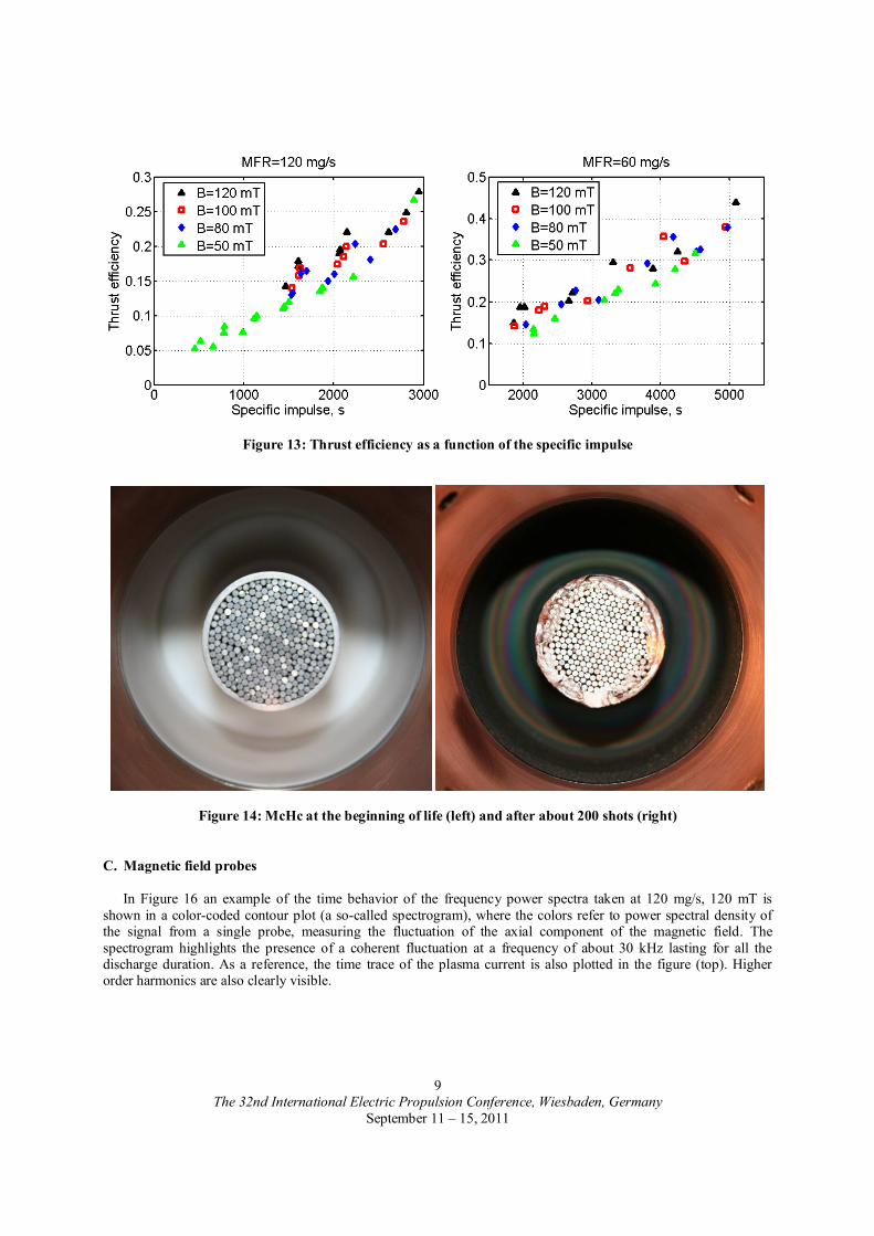
It can be observed from Figure 13 that for all cases presented the thrust efficiency increases with increasing magnetic field. This increase in efficiency is higher for low mass flow rates values. High values of the thrust efficiency at 60 mg/s could be tied with the evaporation of stainless steel from the cathode since, as shown in Figure 14, it was found to suffer of remarkable erosion of the external wall during the early stages of the experimental campaign.
The 32nd International Electric Propulsion Conference, Wiesbaden, Germany
September 11 – 15, 2011
9
Figure 13: Thrust efficiency as a function of the specific impulse
Figure 14: McHc at the beginning of life (left) and after about 200 shots (right)
C. Magnetic field probes
In Figure 16 an example of the time behavior of the frequency power spectra taken at 120 mg/s, 120 mT is shown in a color-coded contour plot (a so-called spectrogram), where the colors refer to power spectral density of the signal from a single probe, measuring the fluctuation of the axial component of the magnetic field. The spectrogram highlights the presence of a coherent fluctuation at a frequency of about 30 kHz lasting for all the discharge duration. As a reference, the time trace of the plasma current is also plotted in the figure (top). Higher order harmonics are also clearly visible.

The 32nd International Electric Propulsion Conference, Wiesbaden, Germany
September 11 – 15, 2011
10
The spatial periodicity along the azimuthal angle associated to the peaks in the spectrogram has been derived by Fourier decomposing, both in time and space, the signals from coils in different positions. The analysis has been performed in the flat-top phase of the discharge (between 200 and 300 ms), in which the frequency associated to the coherent fluctuation is almost constant in time. As can be seen in Figure 15 the main peak, i.e. the one at the lowest frequency, in the spectrum is associated to a m=1 mode number. The presence of higher harmonics, both in the frequency and in the mode number spectra, is an indication that the mode under analysis, having a main m=1 structure, which is basically intended as a shift of the plasma column, corresponds to a magnetic structure localized along the azimuthal angle. This result is in agreement with previous observations in MPD thrusters of different dimension and geometry, where a m/n=1/1 kink mode, destabilized by the violation of the well known Kruskal-Shafranov criterion for the stability of a current-carrying plasma column, was associated to the so-called onset phenomenon in this kind of devices20.
An example of the effect of the operative condition of the thruster (i.e., applied magnetic field strength and mass flow rate) on the spectral properties of the magnetic fluctuation is shown in Figure 15 where the power spectra obtained in three different discharges, at an almost given plasma current (Ip ≈ 1.5 kA) are compared. In particular, two different mass flow rates (dm/dt) and magnetic field values are considered. The spectra appear strongly influenced by the experimental condition, with more pronounced peaks in the discharge with strong applied magnetic field (B=120 mT), which is in agreement with what predicted by the empirical Tikhonov criterion21 for the onset phenomenon in MPD thrusters.
Moreover, according to the Tikhonov criterion, a larger mass flow rate is expected to be associated to a more stable thruster operation, and it is interesting to note that the increase of the mass flow rate has also a stabilizing effect on the plasma instability under investigation, as can be seen in the figure by comparing the two spectra obtained at the same applied magnetic field (B=120 mT). This result further confirms the strong relation between plasma properties and the quality of MPDTs operation, both in terms of stability and efficiency of the propulsive process.
Figure 15: Color-coded azimuthal mode number and frequency Fourier analysis of the axial magnetic field fluctuation in a 120 mg/s and B=120 mT experimental
Figure 16: Top) time trace of the plasma current; bottom) spectrogram (i.e., color-coded contour of the spectral density vs time and frequency) of the signal from a single probe measuring Bz fluctuation.

The 32nd International Electric Propulsion Conference, Wiesbaden, Germany
September 11 – 15, 2011
11
As a final comment about plasma fluctuation, it is interesting to note that not only the amplitude of such fluctuation is affected by both the magnetic field and the mass flow rate, but also its frequency. To elucidate this issue a deeper data analysis is needed, which is still under progress.
Figure 17: Frequency power spectra of Bz fluctuation in three different experimental conditions at a given plasma current (J=1.5 kA).
IV. Conclusions A new quasi-steady AF-MPDT has been designed, manufactured and preliminary tested. The experimental set-
up has proven to be reliable and adequate to perform long (500ms) quasi-steady pulses. The adoption of the Alta’s PFN as thruster ignitor together with a bank of super-capacitors as main power supply has demonstrated to be a cost effective and safe solution. The “ad hoc” developed thrust stand has proven to correctly operate, allowing a real time thrust measurement. The diagnostics for plasma instabilities detection and characterization has demonstrated to properly operate. At 120 mg/s of argon the results gathered so far indicate the thruster reached a maximum of thrust efficiency and specific impulse of about 28% and 3000 s respectively, for an applied magnetic field of 120 mT and a discharge power of about 170 kW. The results at 60 mg/s should be considered with a certain caution since the high erosion of the cathode external wall during the early stage of the test campaign could have affected the data. A complete characterization of the thruster with and without the metallic shield is ongoing and the relevant results will be shown in following papers.
Acknowledgments The authors wish to express their gratitude to Gianluca Cifali, Carlo Tellini and Daniele Dignani for their
valuable assistance in preparing and maintaining the experimental apparatus and for their support throughout. The work described in this paper has been funded by the European Space Agency in the framework of the TRP
project “Technical Assessment for High Power Magneto-Plasma-Dynamic Systems” under the contract 21797/08/ML/PA between the Agency and Alta SpA and by the European Commission in the framework of the HiPER project under the Grant Agreement n° 218859 .

The 32nd International Electric Propulsion Conference, Wiesbaden, Germany
September 11 – 15, 2011
12
References 1G.Kruelle et al., “Technology and Application Aspects of Applied Field MPD Propulsion”,14(5):754-763, Journal of
Propulsion and Power, September-October 1998. 2M.Tanaka et al., “Current Distribution and Plasma Acceleration in MPD Arcjet with Applied Magnetic Fields”, 4(5):428-
436, Journal of Propulsion and Power, September-October 1988. 3F.Paganucci et al., “MHD Instabilities in MPD Thrusters”, 50(12): 4010-4016, Plasma Phys. Control Fusion, November
2008. 4M.Zuin et al., “Critical Regimes and MHD instabilities in MPD thrusters”, 11(10):4761-4770, Physics of Plasmas, 2004. 5G.Serianni et al., “Plasma Diagnostics in an AF-MPD Thruster”, IEPC 01-135, 27nd International Electric Propulsion
Conference, Pasadena, CA, October 2001. 6M.Andrenucci et al., “Scale Effects on the Performance of MPD Thrusters”, IEPC 91-123, 22nd International Electric
Propulsion Conference, Viareggio, Italy, October 1991. 7E.J.Strait et al., “Wall Stabilization of High Beta Tokamak Discharges”, 74(13):2483-2486, Physical Review Letter, 1995. 8T.Hender et al., “ITER Physics. Chapter 3: MHD stability, operational limits and disruptions”, 47(6):S128, Nuclear Fusion,
2007. 9T.Taylor et al., “Wall Stabilization of High Beta plasma in DIII-D”, 2(6):2390-2396, Physics of Plasmas, 1995. 10J.P.Freidberg, “Ideal Magnetohydrodynamics (Modern Perspectives in Energy)”, Plenum Press, New York, 1987. 11R.Paccagnella et al., “Active-Feedback Control of the Magnetic Boundary MHD Stabilization of a Fusion Plasma”,
97(7):075001-075005, Physical Review Letters, 2006. 12A.M.Garofalo et al., “RWM Dynamics and Active Feedback in DIII-D”, 41(9):1171-1176, Nuclear Fusion, 2001. 13M.Okabayashi et al., “Stabilization of the RWM in DIII-D by Plasma Rotation and Magnetic Feedback”, 44(12B):339-355,
Plasma Physics and Control Fusion, 2002. 14Q.Liu et al., “Stabilization of RWMs in ITER by Active Feedback and Toroidal Rotation”, 44(2):232-236, Nuclear Fusion,
2004. 15D.J.Ward et al., “Stabilization of Ideal Modes by Resistive Walls in Tokamaks with Plasma Rotation and its Effect on the
Beta Limit”, 2(5):1570-1581, Physics of Plasmas, 1995. 16F.Paganucci et al., “Performance of an Applied-Field MPD Thruster”, IEPC 01-132, 27th International Electric Propulsion
Conference, Pasadena, CA, October 2001. 17R.M.Myers et al., “Anode Power Deposition in Applied-Field MPD Thrusters”, AIAA-92-3463, 28th Joint Propulsion
Conference and Exhibit, Nashville, TN, July 1992. 18D.Fradkin, “Analysis of Acceleration Mechanisms and Performance of an Applied-Field MPD Arcjet”, Ph.D Thesis,
Princeton University, March 1973. 19V.B.Tikhonov et al., “Performance of a 130 kW MPD Thruster With an External Magnetic Field and Li as Propellant”,
IEPC 97-117, 25th International Electric Propulsion Conference, Cleveland, OH, October 1997. 20M.Zuin et al., “Kink Instability in Applied-Field MPD Thrusters”, 92(22):225003-225006, Physical Review Letters, 2004. 21V.B.Tikhonov et al., “Research of Plasma Acceleration Processes in Self-Field and Applied-Field Thrusters”, IEPC 93-076,
23rd International Electric Propulsion Conference, Seattle, WA, September 1993.