experimental study on novel energy-dissipating
TRANSCRIPT
Research ArticleExperimental Study on Novel Energy-Dissipating PrefabricatedBeam-Column Joints
Qiong Liu Shanghong Chen Wei Lin and Fanjin Zeng
College of Civil Engineering Fuzhou University Fuzhou 350108 China
Correspondence should be addressed to Shanghong Chen chenshanghongfzueducn
Received 16 August 2019 Revised 4 December 2019 Accepted 5 December 2019 Published 23 December 2019
Academic Editor Huu-Tai )ai
Copyright copy 2019 Qiong Liu et al )is is an open access article distributed under the Creative Commons Attribution Licensewhich permits unrestricted use distribution and reproduction in any medium provided the original work is properly cited
A new dapped-end beam to column connection is designed in this paper Its assembly connection zone changes from inside thejoint to midspan of the beam )e proposed connection can not only provide good structural integrity but also ensure that theplastic hinge moves away from the column edge )e rotational capacity of the plastic hinge determines the internal forceredistribution of the joint and the energy dissipation capacity )e high-strength bolts and steel plates are used to realizeconnection further enhancing the rotation of the plastic hinge and minimizing the cast-in-place concrete volume)ree full-scaleexterior beam to column joints are casted and then subjected to reversal cyclic loading)e finite element (FE) analyses are carriedout to compare with experimental results and study the effect of connection position on the structural behaviours )e obtainedresults show that the plastic hinges of all three specimens are firstly developed to a distance from the column edge thus revealingthat this kind of joint can achieve beam hinge mechanism and prevent joint shear failure And the connection position is the mostdisadvantaged when coinciding with the plastic hinge zone which would result in the excessive deformation and the early failureof the steel bar anchor system)e new type of joint shows good seismic performance during earthquake if the connection can beproperly designed and thus this kind of structural form can be applied to actual engineering structures in seismic regions
1 Introduction
Currently fabricated buildings are promoted actively be-cause of their faster construction speed better qualitycontrol and environmentally friendly technology [1] Beam-column joints are acted as the weakest transmission links inprefabricated frames because shear forces are transmittedthrough joint and high shear forces are mainly concentratedin the joint core area under strong earthquake excitations)e postsevere damage of building structures is mainlyattributed to the failure of beam to column joint )us thetransmission properties and the integrity of joints play animportant role in the safety of precast buildings [2]
In order to ensure adequate joint strength different typesof beam-column joints are proposed Prefabricated mono-lithic joints with keyseats are designed and experimentalresults show that the reasonable joint design and the ap-propriate cast-in-site concrete volume can make pre-fabricated joints equivalent to monolithic joints)is kind of
connection is efficient to improve the seismic behaviour inthe high seismic intensity zones [3 4] But the large volumeof cast-in-place concrete may nullify advantages of this kindof joint )is means that cast-in-place monolithic jointscannot facilitate resource saving and friendly environmentPriestley carried out dynamic time history analyses ofprecast prestressed beam-column joints with unbondedtendons Results showed that unbonded tendons can providegood structural integrity and auto-recovery ability for thejoint but the use of prestressed tendons would make theductility and the energy dissipation capacity of this type ofjoint very poor [5ndash7] )is problem is easy to scientificscholars who have devoted great efforts to propose energydissipation dampers which can be attached to the columnand beam ends )e friction dampers are used in the pre-stressed beam-column joints to assume energy andunbonded tendons are used to provide self-centering ca-pacity for joints [8ndash10])e poor energy dissipation capacityof the precast prestressed beam-column joints limits their
HindawiAdvances in Civil EngineeringVolume 2019 Article ID 8151087 17 pageshttpsdoiorg10115520198151087
spreading use but the use of additional energy dissipationdampers can help to absorb energy nevertheless thedampers would interfere with other components of theframe
In the new beam-column joint system prefabricatedcolumns are cast continuously with a free space in theconnection zone to connect the U-shaped beam shell )iskind of joint can provide good structural intergrety in theconnection zone [11ndash13] But the shear strength of jointsdrops due to the reduced column depth in the joint whichmeans that this kind of joint cannot achieve the strong-jointweak-component failure mechanism To face this problemresearchers have proposed alternative methods that canprovide good protection for joints It is well known that theposition of the plastic hinge has significant effects on themechanical performance of joints Chio et al proposed anew type of joint and its U-shaped cross section beam andcolumn were connected by steel plates in the core area )eplastic hinge zone was relocated away from the column edgeby taking advantage of the deformation of the steel plates[14] Furthermore researchers have introduced othermethods to transfer the plastic hinge zone from the columnedge to beam span As an alternative method to protect jointand relocate plastic hinge zones the haunch systems whichwere made of steel bars and joint enlargement were used byPampanin et al [15] and Pimanmas and Chaimahawan [16]Eom et al also used two strengthening methods to achieveplastic hinge relocation such as hooked bars and headedbars Except for strengthening methods reducing beam barsection can also help to transfer plastic hinge zones toweakened beams [17] In 2006 Chen et al introduced anoptimal method to improve ductility and promote the de-velopment of the plastic hinge )is means that the weldingpart of the beam-column joint was enhanced [18] )eplastic hinge moves from the column edge to the cutoff pointof the CFRP and specimens retrofitted by carbon fiber-reinforced polymer exhibit higher bearing capacity andductility [19] Although the above relocation form about theplastic hinge is a good way to avoid the shear failure of jointsthe connection form constructed in the joint core area woulddisturb the continuity of longitudinal steel bars and thecongested reinforcement in the joint would result in diffi-culty in concrete pouring Considering that the flexuralstiffness changes along the lap splice connection of theassembled beam and decreases at the transition section ofthe reduced profile the connection position can be placed onthe midspan of the beam [20] Similarly Astaneh-Asl alsoproposed that the semirigid connection can weaken thedamage caused by seismic energy In addition the con-nection can be allowed to slip so that the earthquake energycan be absorbed through friction between contact surfaces[21] Joshi and Patel conducted experimental studies onprefabricated connections which were constructed awayfrom the junction area )e partial precast beam was con-nected to other prefabricated element through steel platesand the prefabricated element was extended from the edge ofthe column )e test results showed that the proper precastconnection design could ensure the same performance asmonolithic specimens [22] )e short cantilever beam is
casted as part of the precast column extending from thecolumn edge Another precast beam is connected to thecantilever beam through the lapping of the hooks [23 24]Previous studies verified that the seismic performance ofprefabricated structures can be improved and meet thedemand of seismic codes as long as the connections areproperly designed and retrofitted for strength and ductility[25ndash27]
In this paper experimental and numerical analyses ofdapped-end beam to column joints are conducted)e workdevotes to relocating the connection zone from the interiorjoint core area to midspan of the beam so as to achieve beamhinge mechanism Another part of the precast beam is seatedon the dapped-end cantilever beam and coupled to canti-lever beam through high-strength bolts and steel plateswhich can minimize the volume of cast-in-place concreteand get rid of additional strengthening or weakeningsystems
2 Experiments on Joints
21 Specimen Design Figure 1 describes the details of theproposed dapped-end cantilever beam to column joint Inthe system columns are prefabricated with continuouslongitudinal bars in the joint in the same technology asconventional precast members )e cantilever beam withU-shaped groove is extended from the edge of column andanother part of precast beam with corbel is seated on thecantilever beam )e U-shaped cross section groove is re-served at the end of the cantilever beam tomake space for thecorbel Two precast members are connected through high-strength bolts Considering the brittleness of concrete andsmall load-bearing areas of bolts on both sides of theU-shaped groove two rigid steel plates are attached to theexternal surfaces of the U-shaped groove to distribute forcesand avoid stress concentration )e length of the U-shapedgroove is 150mm same as the corbel but the height and thewidth are 300mm and 200mm larger than those of thecorbel so that the connected cast-in-place space for con-creting can be formed after anchorage of the corbel and theU-shaped groove As a result the cast-in-place concrete canprovide integrity for the connection )e horizontal steelbars in the beam are reserved in the column and extendedthrough the cantilever beam to the connection zone Cor-respondingly steel bars are extended from another part ofthe precast beam to the connection zone )ese longitudinalsteel bars at the bottom of the beam are connected bywelding and two longitudinal bars on the top of the beamand lateral longitudinal bars are connected by sleeves in thecast-in-place zone for concreting In the installation processthe bolt shanks are used for position purpose so that thecorbel can be seated on the U-shaped groove precisely
In the installation process the precast column is placederectly and then another precast beam is seated on thecantilever beam )e bolt rods are used for the preciseposition to prevent assembly problem After that the hor-izontal steel bars on the top of the beam are bolted firstfollowed by the lateral bars And the steel bars at the bottomof the beam are connected by welding )en the concrete is
2 Advances in Civil Engineering
poured into the cast-in-place area to integrate the con-nection Finally the pretightening force is applied to thebolts
)e dapped-end beam to column joint can relocate theconnection position from the joint core area to the beamspan which can provide the integrity for the joint In thisway the plastic hinge can also be relocated away from thecolumn edge so that the beam hinge mechanism can beachieved )ree types of joints PC1 PC2 and PC3 aredesigned to be 450mm 600mm and 750mm away from thecolumn edge respectively And it is known that the beamplastic hinge of precast joints is formed at a distance of about10ndash13 times the height of the beam away from the columnedge [17 28] As a result the connection position of jointsPC1 and PC2 coincides with the plastic hinge but theconnection position of joint PC3 is away from the plastichinge zone)e use of high-strength bolts and steel plates forconnection can help to enhance the rotation of the plastichinge thus providing better deformation capacity
)ree full-scale exterior joints in frames (PC1 PC2 andPC3) were fabricated based on the design principles havingthe seismic performance equivalent to cast-in-place joints)ey were designed according to the Chinese Standards ofDetailing of Joints in Precast Concrete Structures (15G310-1sim2 2015) [29] and Technical Specification for PrecastConcrete Structures (JGJ 1-2014 2014) [30] Figure 2 showsthe dimensions and reinforcement details in the joints withdifferent connection positions which were 450mm600mm and 750mm away from column edge respectively)e column had a 400times 400mm cross section and a heightof 2450mm )e longitudinal reinforcements of each col-umn included twelve D22 bars (C22) In order to improvethe strength of the joint the distance of the stirrups was
designed to be 50mm in the joint area In other parts of thejoint the distance between the column stirrup was 100mm)e beam had a 250 times 450mm cross section and a length of1500mm In the cantilever beam within the distance of300mm away from the column edge and the corbel area inthe precast beam the distance of the stirrups was designedto be 50mm In other areas of the beam the distancebetween the beam stirrup was 100mm )e corbel wasregarded as one of the main force elements so a specialsteel bar frame was designed and embedded in the corbelarea to ensure adequate bearing performance which wasmade of concrete with D16 longitudinal steel bars (C16) of400mm and stirrups All stirrups were D8 ordinary steelbars (A8) )e concrete used in the specimens had astrength grade of C30 (nominal cubic compressive strengthfcud 30MPa and design axial compressive strengthfcd 143MPa) High-strength bolts of grade 109 with thediameter of 24mm and the length of 320mm were used forassembling the joints
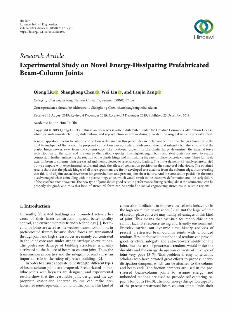
22 Mechanical Analysis of Dapped-End Connection It isessential for the dapped-end connection to transfer the shearforce and the moment effectively )e force transfer systemof the dapped-end connection under vertical load is shownin Figure 3 )e four forces must be in equilibrium in boththe horizontal and vertical directions Vertical shear forcesare transmitted to the core area of the joint by the U-shapedgroove at the end of the cantilever beam and the corbelHence the reliability of the connection mainly depends onthe performance of the groove and the corbel Assuming thatthe mutual friction between concrete interfaces has littleinfluence on the force transfer mechanism the full vertical
13 4 2
65
7
8
(a)
(b)
Figure 1 Beam-column joint details (a) Design schematic diagram (1 column 2 beam 3 U-shaped groove 4 corbel 5 steel plate 6 bolthole 7 cast-in-place area 8 bolt) (b) Photo
Advances in Civil Engineering 3
shear force is sustained by the corbel )e U-shaped groovecan be regarded as a reversed corbel and thus its mechanicalproperties are similar to those of the corbel
Based on the strut-and-tie model the horizontal steelbars at the bottom of the corbel are regarded as the tie rodand internal compressed concrete is viewed as the diagonal
8100
8100850
450
450
40010
0010
001500
2450
1900
Bolt holes
Sleeves2
211
(a)
8100
8100
850 2
21 1
600
400
450
1000
1000
2450
15001900
Boltholes
Sleeves
(b)
8100
850
8100
2
211
400
450
1000
1000
2450
15001900
Bolt holes
Sleeves
750
(c)
400
400
8100
400 times 40012 22
(d)
250
450
2 16
8100
250 times 4506 18
(e)
Figure 2 Dimensions and reinforcement details of PC1 PC2 and PC3 (a) Cross section of beam-column joint of PC1 (b) Cross section ofbeam-column joint of PC2 (c) Cross section of beam-column joint of PC3 (d) Column cross section (e) Beam cross section (in mm)
4 Advances in Civil Engineering
struts )e force diagram of the corbel is shown in Figure 3in which T is the tensile resistance of the steel bars C is thecompression force in the concrete and Fu is the verticalbearing capacity obtained from equations (1)ndash(9)
C Acxfcx (1)
where Acx is the cross-sectional area of the end part per-pendicular to small oblique blocks and fcx is the effectiveconcrete strength of the diagonal struts
Acx
2
radic
2bh (2)
fcx 085βjf0c 085 times 08f
0c (3)
where b and h are the width and the height of the corbelrespectively and f0
c is the compression strength designvalue Considering the effects of cracking development andmultiaxial stress on the compressive strength of diagonalstruts the reduction ratio βj of 08 is used to describe thestrength reduction based on American structure design codeACI Committee 318 [31]
Cl Acxfcx
2
radic
2bh times 085 times 08f
0c (4)
T fy times As (5)
Fu T
2
radic
2C (6)
In order to ensure the safety of diagonal struts and theeffectiveness of tie rods the following formulas must beconsidered
Fu le 034bhf0c (7)
ρs le 034f0
c
fy
(8)
ρs As
bh (9)
where ρs is the reinforcement ratio of tie bars and As is themaximum area of tie rods
According to the above mechanical analysis the strut-and-tie model has effects on the reliability of the corbel andthe bearing capacity of the dapped-end connection )ereinforcement ratio of steel bars and compressive strength ofdiagonal struts both meet the design demands based on theabove design parameters )is means that forces can betransmitted to the joint effectively
23 Load Scheme )e axial force and the horizontal forcewere applied to the joints to simulate the axial load on thecolumn caps and the lateral load from earthquake excita-tions as shown in Figure 4 )e horizontal force was appliedby an actuator with 500 kN capacity and the actuator wasconnected to the strong wall by a pin )e axial force wasapplied from the column top by a jack with 160 t capacity)e upper and lower ends of the column were hinged toeffectively simulate the real boundary condition of thecolumn )e bottom hinge was anchored to the ground andthe upper hinge was attached to the reaction beam through ahydraulic jack Two horizontal bracings were connected tothe reaction wall to ensure the stability and safety of thespecimen in the loading process
During the loading test the axial load was applied to thecolumn by the hydraulic jack with a design axial com-pression ratio of 03 (8016 kN) Considering the specialstructural configuration it is hard to determine the accurateyield displacement and load of three joints in the loadingprocess Displacement control mechanismwas applied at thefree end of the beam by the MTS actuator in the wholeloading process Loading scheme (a) is applied for PC1 asshown in Figure 5(a) Due to the asymmetric design of theconnection it is observed that the structural response of PC1was asymmetric in the experiment )is means that thepositive bearing capacity of the joint is larger than thenegative one )e use of steel plates attached to both sides ofthe cantilever beam is one major reason for the asymmetricresponses In order to avoid the early failure in the negativeloading there is another loading scheme (b) for PC2 and
Fu
Fu
No No
Fu
TC
TFuC
Figure 3 Calculation schematic
Advances in Civil Engineering 5
PC3 (Figure 5(b)) in the later tests In loading scheme (b)the maximum loading displacement of the negative direc-tion is smaller than the positive loading displacement In theelastic stage one loading cycle is performed for each dis-placement step With the test continuing two full loadingcycles are applied at the constant increment of 5mm
3 Experimental Results and Analysis
31 Experiment Phenomena )ere is little difference in thecrack pattern and the failure mode of all three joints asshown in Figure 6 )e joints PC1 and PC2 failed suddenlydue to the steel bar bond slip in the connection area andsignificant concrete crushing whereas joint PC3 kept perfectductile deformation after the yielding of the longitudinalreinforcement Welded rebars at the bottom of the beam inthe joints PC1 and PC2 were fractured during the cyclicloading)is is due to the fact that the connection position ofjoints PC1 and PC2 coincides with the plastic hinge zone andthe inelastic deformation of joints mainly concentrates on
the plastic hinge zone As a result the deformation in theconnection area of joints PC1 and PC2 is so large that theearly connection failure of welded rebars occurred How-ever the welded rebars of joint PC3 were not fractured andshowed obvious yielding stage
For the joint PC1 when the imposed displacement at thebeam end achieved plusmn4mm the first crack appeared at adistance of 100mm away from the column edge With thedisplacement increasing to plusmn10mm several tiny shear cracksappeared around the steel plate and then extended to thebottom of the new-old concrete interface )e size and thenumber of these cracks continued to grow during the testuntil the spacing of the diagonal shear crack grew up to10mm on the bottom of the U-shaped groove at the dis-placement of plusmn30mm After that the welded steel bars dis-connected under the cyclic loading At this time the shear andthe moment were transmitted depending on high-strengthbolts and the strut-and-tie model in the corbel area and thenthe concrete at the bottom of the U-shaped groove was di-vided into small oblique blocks in the direction of the struts
1
2 3
67
6
54
(a) (b)
Figure 4 Experimental setup (a) Schematic diagram (1 reaction beam 2 jack 3 actuator 4 horizontal bracing 5 reaction wall 6displacement meter 7 extensometer) (b) Photo
ndash32ndash28ndash24ndash20ndash16ndash12
ndash8ndash4
048
121620242832
Disp
lace
men
t (m
m)
200 400 600 800 1000 1200 1400 1600 1800 2000 22000
Time (s)
(a)
ndash32ndash28ndash24ndash20ndash16ndash12
ndash8ndash4
048
121620242832
Disp
lace
men
t (m
m)
200 400 600 800 1000 1200 1400 1600 1800 2000 22000Time (s)
(b)
Figure 5 Loading scheme (a) Loading cycles for PC1 (b) Loading cycles for PC2 and PC3
6 Advances in Civil Engineering
According to the test results of joint PC1 it is foundthat the structural response was unsymmetrical in thepositive and negative direction Hence the improvedloading scheme (b) in Figure 5(b) was adopted in theloading process of joints PC2 and PC3 From the test on thejoint PC2 it was observed that the first cracking occurred atthe displacement of +2mm also in some cases initiatingfrom the bottom of the cantilever beam With the loaddisplacement increasing obvious flexural cracks wereconcentrated in the connection zone which can preventexcessive flexural cracks from extending to the columnedge Many diagonal cracks occurred at the loading dis-placement of plusmn8mm starting from the new-to-old concreteinterface and then propagating toward the compressionzone of the new-to-old concrete interface At this stage aseries of concrete struts may be formed in the corbelDuring the sequential loading cycles more shear crackswith increasing width appeared at the bottom of the beamin the connection zone until the concrete was crushed andsteel bars were exposed at the displacement of minus 25mm Atthe end of the test the significant diagonal crack whichinitiated from the bottom of the U-shaped groove pene-trated transversely through the whole beam sectionresulting in significant concrete separation
)e final failure mode of joint PC3 was different fromthat of joints PC1 and PC2 In the initial loading stage thefirst flexural crack appeared at the new-to-old concreteinterface at the displacement of +4mm After that moreflexural cracks developed and extended along the beam toshear spans until some flexural cracks coincided with shearcracks After the yielding of the main longitudinal steel barthe diagonal cracks propagated rapidly and the concrete atthe bottom of the beam was crushed significantly
In general the largest damage can be observed in thespecimen PC1 followed by the specimens PC2 and PC3which displayed a reduced number of cracks in the con-nection zone)emaximum shear crack width at the bottomof the beam in three joints was 8mm 6mm and 5mmrespectively As for specimens PC1 and PC2 the connectionposition is 450mm and 600mm away from the column edgethus coinciding with the inherent plastic hinge zone )eplastic hinge of precast joints is formed at a distance of about10ndash13 times the height of the beam away from the column
edge )us the connection position of joint PC1 is the mostdisadvantageous position under the cyclic loading and theweakest part in the whole structure )e rotation of theplastic hinge in the joint PC1 can enhance the deformationof the beam which resulted in the widest crack Howeverthe connection position of joint PC3 is designed to be750mm away from the column edge so as to avoid coin-ciding with the plastic hinge region As a result the joint PC3exhibited better mechanical properties which had bothhigher strength and ductility
It is worth noting that the cracks in the specimens weremainly concentrated in the connection zone which can helpto prevent the development of excessive cracks in the joint Itcan thus be concluded that the plastic hinge was confined tothe beam successfully by relocating the connection positionto midspan of the beam It can also be found that there weresome cracks initiating from the column edge and thenextending along with the beam longitudinal bars which canbe explained by the bond slip of steel bars under the cyclicloading
32 Load-DisplacementHysteresis Curve Figure 7 shows thehysteresis curves of specimens PC1 PC2 and PC3 It isobvious that the curve shape is unsymmetrical both in thepositive and negative condition which can be explained byenforcement effects of steel plates attached to both sides ofthe cantilever beam At the elastic stage the relationshipbetween lateral load and displacement is linear With thelateral load increasing some steel bars begin to yield and theslope of the hysteresis loops decreases slowly due to the crackdevelopment After reaching the peak load the significantdegradation in strength is observed in the joints PC1 andPC2 which can be attributed to the early connection failureof longitudinal steel bars in the connection zone under thecyclic loading but the load-displacement curve of joint PC3remains pretty stable )e hysteresis loops of joints PC1 andPC2 in the loading cycles are more pinched and show greaterstiffness degradation as compared to joint PC3 which haslarger hysteresis loops and reveals higher energy dissipationcapacity )is is because significant concrete spalling occursin the plastic hinge zone in the specimens PC1 and PC2However the connection position of PC3 does not coincide
(a) (b) (c)
Figure 6 Crack distribution of (a) PC1 (b) PC2 and (c) PC3
Advances in Civil Engineering 7
with the plastic hinge zone hence the damage of the beam isreduced It can also be found that the peak load of the secondcycle is smaller than that of the first cycle which can beexplained by the stiffness degradation due to the materialdamage )e trend is particularly noticeable in the speci-mens PC1 and PC2 which suffer more significant concretecrushing in the connection area
33 Energy Dissipation Capacity )e energy dissipationcapacity can be used to describe the ductile behaviour ofstructures It can be measured based on the area circled bythe hysteretic loop For the curves with double cycles at thesame displacement level the average value of the area intwo cycles is calculated as the energy dissipation coefficientaccording to the formulas provided in the Test Code forEarthquake Resistant Building (JGJT101-2015 2015) [32])e equivalent viscous damper ratio is also an importantindex to measure energy dissipation capacity which canalso be obtained from the hysteresis curve As shown in
Figure 8 the energy dissipation coefficient and theequivalent viscous damper ratio are calculated by thefollowing equations
E S(ABC + CDA)
S(OBE + ODF) (10)
ζeq 12Π
S(ABC + CDA)
S(OBE + ODF) (11)
where E is the energy dissipation coefficient ζeq is theequivalent viscous damper ratio being the ratio of thedissipated energy of the hysteretic loop to the strain energydivided by the constant 2π S (ABC+CDA) is the area of thehysteresis loop and S (OBE+ODF) is the area of trianglesOBE and ODF
)e energy dissipation coefficient E and the equivalentviscous damper ratio ζeq of three specimens are summarizedin Table 1 For the joint PC1 a larger amount of energy isabsorbed as compared to specimens PC2 and PC3 when the
PC1
ndash200
ndash150
ndash100
ndash50
0
50
100
150
200
250Lo
ad (k
N)
ndash30 ndash25 ndash20 ndash15 ndash10 ndash5 0 5 10 15 20 25 30 35ndash35
Displacement (mm)
(a)
PC2
ndash200
ndash150
ndash100
ndash50
0
50
100
150
200
250
Load
(kN
)
ndash30 ndash25 ndash20 ndash15 ndash10 ndash5 0 5 10 15 20 25 30 35ndash35
Displacement (mm)
(b)
PC3
ndash200
ndash150
ndash100
ndash50
0
50
100
150
200
250
Load
(kN
)
ndash30 ndash25 ndash20 ndash15 ndash10 ndash5 0 5 10 15 20 25 30 35ndash35
Displacement (mm)
(c)
Figure 7 Hysteresis curves of the specimens (a) PC1 (b) PC2 (c) PC3
8 Advances in Civil Engineering
loading displacement is less than 8mm )e energy dissi-pation coefficient E of joint PC1 is 04765 larger than that ofjoints PC2 and PC3 of about 04462 and 03973 respectively)is is because the relocation of the plastic hinge increasesthe deformation capacity of the whole structure and leads tomore cracks in the beginning loading In fact deformationand cracking provide a way to absorb energy thereforemore cracks and deformation in the specimen PC1 con-tribute to higher energy dissipation capacity )e maximumenergy dissipation coefficient E of joints PC1 and PC2 isobtained at the displacement of 20mm and then decreasesgradually whereas the energy dissipation coefficient E ofjoint PC3 continues to increase until the end of the loadingprocess )is can be attributed to the excessive deformationand significant concrete spalling in the joints PC1 and PC2which result in significant reduction of the bearing capacity)e equivalent viscous damper ratio ζeq is used to describethe energy dissipation capacity during each cycle )eequivalent viscous damper ratio ζeq achieves the maximumof 01570 at the displacement of 20mm for joint PC1 and themaximum value of 01686 is obtained at the displacement of15mm for joint PC2 After that the equivalent viscousdamper ratio ζeq decreases with the displacement increasing)e obvious inflection points imply that joints PC1 and PC2have been severely damaged in the loading process For jointPC3 its equivalent viscous damper ratio keeps rising andachieves 01530 at the displacement of 30mm
Figure 9 further compares the cumulative energy dis-sipation of three specimens and similar conclusions can bedrawn At the elastic stage there is no obvious difference inthe cumulative energy dissipation capacity of test specimensAfter the loading displacement increases to 15mm thecumulative energy dissipation capacity of joint PC3 exceedsthat of joints PC1 and PC2 )is is because some longitu-dinal steel bars in the joints PC1 and PC2 fracture and do notfunction effectively during the cyclic loading whereas thereinforcement detailing in the connection zone of joint PC3is still effective
34 Skeleton Curve )e skeleton curves of all three jointscan be obtained by picking up the ultimate load under each
displacement level )e skeleton curves of three joints arealso unsymmetrical as shown in Figure 10 )e upper steelplates anchored to both sides of the cantilever beam help toachieve larger strength in the positive direction )e criticaldata about skeleton curves are summarized in Table 2 )ejoint PC1 reaches the ultimate positive load of 18868 kN atthe displacement of +997mm and the negative load of11922 kN is obtained at the displacement of minus 840mm(Figure 10(a)) )e ultimate load of joint PC2 is slightlyhigher than that of joint PC1 with 20713 kN at the dis-placement of +1003mm and 1323 kN at the displacementof minus 744mm (Figure 10(b)) )e bearing capacity is mainlydetermined by steel bars however the longitudinal steel barsat the bottom of the beam in the joints PC1 and PC2 aredisconnected earlier than the concrete crushing )ereforethe bearing capacity of joint PC3 with integral bar con-nection under cyclic loads is the largest and the ultimateload achieves 23492 kN and 18617 kN in the positive andnegative direction respectively It can be seen that theskeleton curves of three joints are almost identical at theelastic stage which indicates that three joints achieve thesimilar initial stiffness But with the cyclic load increasingthe stiffness begins to decline to some extent which is mainlycaused by the plastic damage of concrete and the yielding ofsteel bars Considering significant concrete cracking of jointsPC1 and PC2 before yielding of main longitudinal steel barsin the beam the significant strength degradation of jointsPC1 and PC2 can be observed in the sequential loadingcycles It is also found that there is no obvious yield platformexcept for joint PC3 )is is because the yielding strength ofbeam steel bars is high whereas the steel bar anchor systemin the joints PC1 and PC2 fails before reaching yieldingstrength )e connection position of joints PC1 and PC2coincides with the plastic hinge zone and the inelasticdeformation of joints mainly concentrates on the plastichinge zone so that significant concrete spalling occurs in theplastic hinge zone in the beam of joints PC1 and PC2 but theconnection position of joint PC3 does not coincide with theplastic hinge zone hence the damage of the beam isreduced
35 Stiffness Degradation )e stiffness degradation canreflect the structural damage under earthquake loadingsWhen subjected to identical loading displacement level thestiffness drops with the number of unloading-reloadingcycles increasing )e average conversion value of the ringstiffness can be used to describe the stiffness degradation asshown in the following equation
K 1113936
ni1P
ij
1113936ni1Δ
ij
(12)
where Kis the ring stiffness Δijis the displacement at the
peak state of the ith cycle at the jth loading level n is the cyclenumbers (n 2) and Pi
j is the maximal load of the ith cycle atthe jth loading level )e stiffness degradation curves of threespecimens are shown in Figure 11
Displacement
Load
B
F
D
A 0 EC
Figure 8 Calculation diagram
Advances in Civil Engineering 9
For all three joints the positive stiffness is larger than thenegative one because of the enhancement effect of steelplates on both sides of the cantilever beam )e stiffnessdifference is more obvious after the cracking of the new-to-old concrete interface All joints show sharp stiffness deg-radation in the initial displacement level due to the de-velopment of cracks With the displacement level increasingthe crack development slows down and the stiffness deg-radation tends to be stable)e positive stiffness of joint PC2is larger than that of joint PC1 in the initial loading cyclesbut their stiffness degradation curves coincide with eachother in the later loading cycles )e negative stiffness ofjoint PC2 drops faster than that of joint PC1 in the laterloading cycles )e stiffness degradation of joints PC1 andPC2 is faster than that of joint PC3 which may be attributedto the early failure of the steel bar anchor system
4 Numerical Model
Except for the test observations finite element analyses arecarried out to enable further understanding of behaviours ofthe dapped-end connection )e FE models P1 P2 and P3are developed by ABAQUS software FE models areestablished based on the actual conditions of the test such as
boundary conditions and loading patterns as shown inFigure 12(a) )e concrete plasticity damage is consideredfor both the column and beam so tensile cracking andcompressive crushing can be exhibited in the model Allconcrete members are modelled by tridimensional hex-ahedral solid element (C3D8R-type) and two-node linear3D truss elements (T3D2-type) are used to model steel bars)e steel framework is embedded into the whole model thusexhibiting no obvious steel bar bond slip )e contact in-teraction between the U-shaped groove and the corbel isintroduced to define the assemblage effects )e dense meshcan improve the accuracy but would result in the excessivecomputed quantity therefore only steel plates and boltsadopt dense meshes )e finite element meshes of the jointare shown in Figure 12(b) )e axial load is applied to thecolumn which is set as pressure load and the cyclic load isapplied with inverse position from up and down Boltpretightening forces are applied in step to make sure thecontact stability
5 Comparison between Numerical andExperimental Results
Figure 13 shows the load-displacement curves of FE modelsIt can be seen that the hysteresis curves of numerical analysesfor three joints P1 P2 and P3 are slightly different fromthose hysteresis curves measured in the experiment )elargest difference is that the hysteresis curves of experimentalresults show significant pinching whereas the hysteresiscurves of numerical results show less pinching which can beattributed to the perfect bar bond behaviours in the nu-merical model At the elastic stage the stiffness of numericalresponses for three joints is larger than experimental re-sponses )is can be explained by the effect of pins in thepractice which are not ideal confines After reaching thepeak load the experimental curves of joints PC1 and PC2drop suddenly because of the connection failure of steel barsand significant concrete crushing whereas the numericalcurve just begins to drop gradually due to the plastic damageof concrete materials But the numerical response of joint P3is similar to the experimental response still remaining stableafter exceeding the peak load and showing the better energydissipation capacity
)e comparison of skeleton curves is shown in Figure 14It can be seen that the load-displacement envelops of nu-merical models show obvious yielding stage whether theconnection position coincides with the plastic hinge zone or
Table 1 Energy dissipation coefficient (E) and equivalent damping coefficient ratio ζeq
Loading displacement (mm)PC1 PC2 PC3
E ζeq E ζeq E ζeq6 04216 00731 03870 00619 03866 006168 04765 00759 04462 00710 03973 0063310 05129 00817 05216 00831 04381 0069815 08366 01332 08185 01686 07710 0122820 09158 01570 09020 01500 08445 0134525 07996 01273 08644 01376 08827 0140630 07552 01203 06820 01086 09607 01530
PC1PC2PC3
0
2000
4000
6000
8000
10000
12000
14000
16000
Ener
gy d
issip
atio
n (k
Nmiddotm
m)
5 10 15 20 25 300Displacement (mm)
Figure 9 Comparison of cumulative energy dissipation
10 Advances in Civil Engineering
not )is is because the steel bars are merged as a whole steelframe and then embedded into the concrete thus showingthe perfect bond properties As a result three FE models donot fail suddenly due to the disconnected anchor system andthey keep perfect ductility capacity after the yielding oflongitudinal steel bars
6 Connection Position Effect
)e connection position is the main variable that has asignificant influence on the behaviours of dapped-endbeam to column joints In the experimental work theconnection position is designed to be 450mm 600mm
PC1
ndash200
ndash150
ndash100
ndash50
0
50
100
150
200
250Lo
ad (k
N)
ndash30 ndash25 ndash20 ndash15 ndash10 ndash5 0 5 10 15 20 25 30 35ndash35
Displacement (mm)
(a)
PC2
ndash200
ndash150
ndash100
ndash50
0
50
100
150
200
250
Load
(kN
)
ndash30 ndash25 ndash20 ndash15 ndash10 ndash5 0 5 10 15 20 25 30 35ndash35
Displacement (mm)
(b)
PC3
ndash200
ndash150
ndash100
ndash50
0
50
100
150
200
250
Load
(kN
)
ndash30 ndash25 ndash20 ndash15 ndash10 ndash5 0 5 10 15 20 25 30 35ndash35
Displacement (mm)
(c)
Figure 10 Skeleton curves of specimens (a) PC1 (b) PC2 (c) PC3
Table 2 Summary of results
Specimen DirectionInitial cracking Yielding of main rebar Ultimate state
Δcr (mm) Pcr (kN) Δy (mm) Py (kN) Δu (mm) Pu (kN)
PC1 Positive 4 6445 758 16695 997 18868Negative 4 7559 612 9992 840 11922
PC2 Positive 2 6967 843 19227 1003 20713Negative 4 7996 656 11956 844 13226
PC3 Positive 4 11209 975 20849 1447 23492Negative 4 10091 848 16392 1150 18617
Advances in Civil Engineering 11
and 750mm away from the column edge )e experimentalresults can confirm the reliability of the FE model based onthe fact that numerical analysis results can basically agreewith the experimental results In order to further under-stand the effects of connection position on the structuralbehaviours FEmodels P4 and P5 are supplemented and theparameter setting is similar to joints P1 P2 and P3 )econnection position of P4 and P5 is designed to be 900mmand 1050mm away from the column edge respectivelyFigures 15 and 16 show the hysteresis curves and skeletoncurves of FE models )e connection position of joints P1
and P2 is within the plastic hinge zone whereas for jointsP3 P4 and P5 the connection position is relocated to adistance of 750mm 900mm and 1050mm away from thecolumn edge thus not coinciding with the plastic hingezone )e inelastic deformation of joints mainly occurredin the plastic hinge zone so the deformation in the con-nection area of joints P1 and P2 is larger than that of otherparts which results in the early connection failure Afterreaching the peak load the bearing capacity of P1 and P2decreases gradually )e maximum load of P1 and P2 is19794 kN and 19071 kN smaller than that of P3 P4 and
(a) (b)
Figure 12 (a) Boundary conditions (b) Meshes of FE models
PC1PC2PC3
0
5
10
15
20
25
30
35
Ring
stiff
ness
(kN
mm
)
0
5
10
15
20
25
30
35
ndash20 ndash10 0 10 20 30ndash30Displacement (mm)
Figure 11 Ring stiffness-displacement curves
12 Advances in Civil Engineering
PC1P1
ndash300
ndash200
ndash100
0
100
200
300
Load
(kN
)
ndash20 ndash10 0 10 20 30ndash30Displacement (mm)
(a)
PC2P2
ndash300
ndash200
ndash100
0
100
200
300
Load
(kN
)
ndash20 ndash10 0 10 20 30ndash30Displacement (mm)
(b)
PC3P3
ndash300
ndash200
ndash100
0
100
200
300
Load
(kN
)
ndash20 ndash10 0 10 20 30ndash30Displacement (mm)
(c)
Figure 13 Comparison of hysteresis curves between numerical analyses and experimental results
PC1P1
ndash300
ndash200
ndash100
0
100
200
300
Load
(kN
)
ndash20 ndash10 0 10 20 30ndash30Displacement (mm)
(a)
PC2P2
ndash300
ndash200
ndash100
0
100
200
300
Load
(kN
)
ndash20 ndash10 0 10 20 30ndash30Displacement (mm)
(b)
Figure 14 Continued
Advances in Civil Engineering 13
PC3P3
ndash300
ndash200
ndash100
0
100
200
300
Load
(kN
)ndash20 ndash10 0 10 20 30ndash30
Displacement (mm)
(c)
Figure 14 Comparison of skeleton curves between numerical analyses and experimental results
P1
ndash300
ndash200
ndash100
0
100
200
300
Load
(kN
)
ndash20 ndash10 0 10 20 30ndash30Displacement (mm)
(a)
P2
ndash300
ndash200
ndash100
0
100
200
300Lo
ad (k
N)
ndash20 ndash10 0 10 20 30ndash30Displacement (mm)
(b)
P3
ndash20 ndash10 0 10 20 30ndash30Displacement (mm)
ndash300
ndash200
ndash100
0
100
200
300
Load
(kN
)
(c)
P4
ndash300
ndash200
ndash100
0
100
200
300
Load
(kN
)
ndash20 ndash10 0 10 20 30ndash30Displacement (mm)
(d)
Figure 15 Continued
14 Advances in Civil Engineering
P5 Both the hysteresis curves of P1 and P2 exhibit sig-nificant pinching in the cyclic loading which reveals thatmore significant bar bond slip and concrete crushing ap-pear in the joints P1 and P2 As for joints P3 P4 and P5 theconnection position is far away from the plastic hinge zone)ey show similar cyclic responses and the spindle-shapedhysteresis loops reveal that joints P3 P4 and P5 have goodenergy dissipation capacity With the connection movingaway from the plastic hinge zone the peak load of joints P3P4 and P5 is 23106 kN 25195 kN and 27742 kN re-spectively )is occurs due to the fact that the connectionposition does not coincide with the inherent plastic hingezone and the connection position of joints P4 and P5 is alsonot in the midspan of the beam As a result the bearingcapacity of joints P4 and P5 is slightly larger than that of P3
7 Conclusions
In this paper a new type of dapped-end beam to columnconnection is proposed which can provide integrity for thejoint and help to achieve the strong-column weak-beam andstrong-joint weak member failure mechanism )e quasi-static tests were carried out to analyze the influence of theconnection location on structural responses and mechanicalproperties Based on the test results FE analyses were carriedout to further understand behaviours of the dapped-endconnection )e major conclusions obtained are as follows
Comparing the failure mode of three specimens in thetest the damage was mainly concentrated in the connectionarea )is means that the connection is the weakest part inthe whole structural system Because the connection isconstructed away from the beam to column junction theplastic hinge is relocated from the column edge to beamspan which could effectively protect the joint core areaDuring the whole loading process there were few cracks inthe joint core area and the column so strong-joint weak-component and strong-column weak-beam principles canbe achieved After the new-old concrete interface crackingthe high-strength bolts and the strut-to-tie model were usedto act as force transfer mechanism)e bolts performed verywell in the whole loading process and provided good frictionand tight force for joints after the disconnection of longi-tudinal steel bars of PC1 and PC2
)e positive bearing capacity of three test specimens waslarger than that of the negative bearing capacity which can beattributed to the strengthening method (two steel plates onboth sides of the U-shaped groove))e bearing capacity andthe energy dissipation capacity of PC3 had more advantagesthan that of PC1 and PC2 In fact the plastic hinge of precastjoints is formed at a distance of about 10ndash13 times theheight of the beam away from the column edge )ereforethe plastic hinge zone of PC1 and PC2 is relocated to theconnection area the weakest part of the beam However theplastic hinge zone of PC3 is positioned in the area away from
P5
ndash300
ndash200
ndash100
0
100
200
300
Load
(kN
)ndash20 ndash10 0 10 20 30ndash30
Displacement (mm)
(e)
Figure 15 Hysteresis curves of numerical models
P1P2P3
P4P5
ndash20 ndash10 0 10 20 30ndash30Displacement (mm)
ndash300
ndash200
ndash100
0
100
200
300
Load
(kN
)
Figure 16 Skeleton curves of numerical models
Advances in Civil Engineering 15
the connection part As a result the plastic hinge rotation ofPC1 and PC2 was larger than that of PC3 which resulted inthe excessive deformation of the beam and the large strengthreduction
From the comparison between the finite element analysisresults and the experimental results it is found that thenumerical results can agree with experimental results butlittle difference can be observed in the specimens P1 and P2which can be explained by the effects of steel bar bond slip atthe bottom of the beam )is means that the overall reli-ability of numerical models can be verified
In order to further study the effects of the connectionposition on the structural behaviours FE models P4 and P5were supplemented based on the comparison results betweenexperimental responses and numerical analyses It is found thecyclic response of P3 P4 and P5 was similar but the bearingcapacity of P4 and P5 was larger )is can be attributed toeffects of connection position which neither coincides withthe plastic hinge zone nor coincides with the midspan part
When the connection is constructed in the beam-col-umn junction joints would not only be subjected to largeamounts of internal forces but also have difficulties inconstruction technology due to the heavily congested re-inforcement in the joint core area However relocating theconnection to the beam span can achieve the minimalamount of forces and deal with worry about the constructionquality Also the connection relocation can help to restraindiagonal cracking in the joint and achieve beam hingemechanism )e major inelastic deformation appears in theconnection area and the plastic hinge zone so that thestrong-joint weak-component and strong-column weak-beam mechanisms can be achieved
Data Availability
)e data used to support the findings of the study are in-cluded in the article
Conflicts of Interest
)e authors declare there are no conflicts of interest re-garding the publication of the paper
Acknowledgments
)e authors are grateful for the financial support providedby the National Natural Science Foundation of China (nos51578159 51678158 51878181 and 51608128) the Programfor New Century Excellent Talents at Fujian ProvinceUniversity (2016 no 83016017) the Cooperative Project ofFujian Province Colleges and Universities (no 2016H6011)the Natural Science Foundation of Fujian Province (no2018J01773) and the Cooperative Leading Project of FujianProvince Colleges and Universities (no 2017H0016)
References
[1] H Wang E M Marino P Pan H Liu and X Nie ldquoEx-perimental study of a novel precast prestressed reinforced
concrete beam-to-column jointrdquo Engineering Structuresvol 156 pp 68ndash81 2018
[2] G Santarsiero and A Masi ldquoSeismic performance of RCbeam-column joints retrofitted with steel dissipation jacketsrdquoEngineering Structures vol 85 pp 95ndash106 2015
[3] H Parastesh I Hajirasouliha and R Ramezani ldquoA newductile moment-resisting connection for precast concreteframes in seismic regions an experimental investigationrdquoEngineering Structures vol 70 pp 144ndash157 2014
[4] J I Resreepo and P Robert ldquoDesign of connections ofearthquake resisting precast reinforced concrete perimeterframesrdquo PCI Journal vol 40 no 5 pp 68ndash76 1995
[5] M J N Priestley and J R Tao ldquoSeismic response of precastprestressed concrete frames with partially debonded ten-donsrdquo PCI Journal vol 38 no 1 pp 58ndash69 1993
[6] M J N Priestley and G A Macrae ldquoSeismic tests of precastbeam-to-column joint subassemblages with unbonded ten-donsrdquo PCI Journal vol 41 no 1 pp 64ndash81 1996
[7] M Priestley S Sritharan J R Conley and S S PampaninldquoPreliminary results and conclusions from the press five storyprecast concrete test buildingrdquo PCI Journal vol 44 no 6pp 42ndash66 1999
[8] B G Morgen and Y C Kurama ldquoSeismic Design offriction-damped precast concrete frame structuresrdquoJournal of Structural Engineering vol 133 no 11pp 1501ndash1511 2007
[9] X Lu Y Cui J Liu and W Gao ldquoShaking table test andnumerical simulation of a 12-scale self-centering reinforcedconcrete framerdquo Earthquake Engineering amp Structural Dy-namics vol 44 no 12 pp 1899ndash1917 2015
[10] F Sarti T Smith S Pampanin et al ldquoExperimental andanalytical study of replaceable buckling-restrained fused-type(BRF) mild steel dissipatersrdquo in Proceedings of the NewZealand Society for Earthquake Engineering AnnualConference Wellington New Zealand April 2013
[11] D Guan Z Guo Q Xiao and Y Zheng ldquoExperimental studyof a new beam-to-column connection for precast concreteframes under reversal cyclic loadingrdquo Advances in StructuralEngineering vol 19 no 3 pp 529ndash545 2016
[12] H J Im H G Park and T S Eom ldquoCyclic loading test forreinforced-concrete-emulated beam-column connection ofprecast concrete moment framerdquo ACI Structural Journalvol 110 no 1 pp 115ndash126 2013
[13] S H Kim J H Moon and L H Lee ldquoAn experimental studyof the structural behaviour on the precast concrete beam-column interior joint with splice type reinforcing barsrdquoJournal of the Architectural Institute of Korea Structure ampConstruction vol 20 no 10 pp 53ndash61 2004
[14] H K Chio Y C Chio and C S Chio ldquoDevelopment andtesting of precast concrete beam-to-column connectionsrdquoEngineering Structures vol 56 pp 1820ndash1835 2013
[15] S Pampanin C Christopoulos and T Chen ldquoDevelopmentand validation of a metallic haunch seismic retrofit solutionfor existing under-designed RC frame buildingsrdquo EarthquakeEngineering vol 16 no 1 pp 21ndash42 2006
[16] A Pimanmas and P Chaimahawan ldquoShear strength of beam-column joint with enlarged joint areardquo Engineering Structuresvol 32 no 9 pp 2529ndash2545 2010
[17] T S Eom H G Park H J Hwang et al ldquoPlastic hingerelocation methods for emulative PC beam-column con-nectionsrdquo Journal of Structural Engineering vol 142 no 2pp 1ndash13 2016
[18] C-C Chen C-C Lin and C-H Lin ldquoDuctile momentconnections used in steel column-tree moment-resisting
16 Advances in Civil Engineering
framesrdquo Journal of Constructional Steel Research vol 62no 8 pp 793ndash801 2006
[19] O Arowojolu A Ibrahim M K Rahman M Al-Osta andA H Al-Gadhib ldquoPlastic hinge relocation in reinforcedconcrete beam-column joint using carbon fiber-reinforcedpolymerrdquo Advances in Structural Engineering vol 22 no 14pp 2951ndash2965 2019
[20] J H Khoo B Li and W K Yip ldquoTests on precast concreteframes with connections constructed away from columnfacesrdquo ACI Structural Journal vol 103 no 1 pp 18ndash27 2006
[21] A A Astaneh Seismic Design of Steel Column-Tree Moment-Resisting Frames Structural Steel Educational CouncilMoraga CA USA 1997
[22] D D Joshi and P V Patel ldquoExperimental study of precast dryconnections constructed away from beam-column junctionunder progressive collapse scenariordquo Asian Journal of CivilEngineering vol 20 no 2 pp 209ndash222 2019
[23] C W French O Amu and C Tarzikhan ldquoConnectionsbetween precast elements-failure outside connection regionrdquoJournal of Structural Engineering vol 115 no 2 pp 316ndash3401989
[24] C W French M Hafner and V Jayashankar ldquoConnectionsbetween precast elements-failure within connection regionrdquoJournal of Structural Engineering vol 115 no 12 pp 3171ndash3192 1989
[25] M Savoia N Buratti and L Vincenzi ldquoDamage and collapsesin industrial precast buildings after the 2012 Emilia earth-quakerdquo Engineering Structures vol 137 pp 162ndash180 2017
[26] C E Chalioris and K E Bantilas ldquoShear strength of rein-forced concrete beam-column joints with crossed inclinedbarsrdquo Engineering Structures vol 140 pp 241ndash255 2017
[27] F Faleschini L Hofer M A Zanini M dalla Benetta andC Pellegrino ldquoExperimental behavior of beam-column jointsmade with EAF concrete under cyclic loadingrdquo EngineeringStructures vol 139 pp 81ndash95 2017
[28] R Park and D K Bull ldquoSeismic resistance of frames incor-porating precast prestressed concrete beam shellsrdquo PCIJournal vol 31 no 4 pp 54ndash93 1986
[29] China Architecture Design Institute 15G310-1sim2 Construc-tion of Assembled Concrete Connection Joints China PlanningPress Beijing China 2015 in Chinese
[30] China Architecture Design Institute JGJ 1-2014 TechnicalSpecification for Assembled Concrete Structure China Ar-chitecture and Building Press Beijing China 2014 inChinese
[31] ACI Committee318 Building Code Requirements for Struc-tural Concrete (ACI 318-02) and Commentary (ACI 318R-02)American Concrete Institute Farmington Hills MI USA2001
[32] China Academy of Building Research Test Code for Earth-quake Resistant Building JGJT101-2015 China Architectureand Building Press Beijing China 2015 in Chinese
Advances in Civil Engineering 17
International Journal of
AerospaceEngineeringHindawiwwwhindawicom Volume 2018
RoboticsJournal of
Hindawiwwwhindawicom Volume 2018
Hindawiwwwhindawicom Volume 2018
Active and Passive Electronic Components
VLSI Design
Hindawiwwwhindawicom Volume 2018
Hindawiwwwhindawicom Volume 2018
Shock and Vibration
Hindawiwwwhindawicom Volume 2018
Civil EngineeringAdvances in
Acoustics and VibrationAdvances in
Hindawiwwwhindawicom Volume 2018
Hindawiwwwhindawicom Volume 2018
Electrical and Computer Engineering
Journal of
Advances inOptoElectronics
Hindawiwwwhindawicom
Volume 2018
Hindawi Publishing Corporation httpwwwhindawicom Volume 2013Hindawiwwwhindawicom
The Scientific World Journal
Volume 2018
Control Scienceand Engineering
Journal of
Hindawiwwwhindawicom Volume 2018
Hindawiwwwhindawicom
Journal ofEngineeringVolume 2018
SensorsJournal of
Hindawiwwwhindawicom Volume 2018
International Journal of
RotatingMachinery
Hindawiwwwhindawicom Volume 2018
Modelling ampSimulationin EngineeringHindawiwwwhindawicom Volume 2018
Hindawiwwwhindawicom Volume 2018
Chemical EngineeringInternational Journal of Antennas and
Propagation
International Journal of
Hindawiwwwhindawicom Volume 2018
Hindawiwwwhindawicom Volume 2018
Navigation and Observation
International Journal of
Hindawi
wwwhindawicom Volume 2018
Advances in
Multimedia
Submit your manuscripts atwwwhindawicom

spreading use but the use of additional energy dissipationdampers can help to absorb energy nevertheless thedampers would interfere with other components of theframe
In the new beam-column joint system prefabricatedcolumns are cast continuously with a free space in theconnection zone to connect the U-shaped beam shell )iskind of joint can provide good structural intergrety in theconnection zone [11ndash13] But the shear strength of jointsdrops due to the reduced column depth in the joint whichmeans that this kind of joint cannot achieve the strong-jointweak-component failure mechanism To face this problemresearchers have proposed alternative methods that canprovide good protection for joints It is well known that theposition of the plastic hinge has significant effects on themechanical performance of joints Chio et al proposed anew type of joint and its U-shaped cross section beam andcolumn were connected by steel plates in the core area )eplastic hinge zone was relocated away from the column edgeby taking advantage of the deformation of the steel plates[14] Furthermore researchers have introduced othermethods to transfer the plastic hinge zone from the columnedge to beam span As an alternative method to protect jointand relocate plastic hinge zones the haunch systems whichwere made of steel bars and joint enlargement were used byPampanin et al [15] and Pimanmas and Chaimahawan [16]Eom et al also used two strengthening methods to achieveplastic hinge relocation such as hooked bars and headedbars Except for strengthening methods reducing beam barsection can also help to transfer plastic hinge zones toweakened beams [17] In 2006 Chen et al introduced anoptimal method to improve ductility and promote the de-velopment of the plastic hinge )is means that the weldingpart of the beam-column joint was enhanced [18] )eplastic hinge moves from the column edge to the cutoff pointof the CFRP and specimens retrofitted by carbon fiber-reinforced polymer exhibit higher bearing capacity andductility [19] Although the above relocation form about theplastic hinge is a good way to avoid the shear failure of jointsthe connection form constructed in the joint core area woulddisturb the continuity of longitudinal steel bars and thecongested reinforcement in the joint would result in diffi-culty in concrete pouring Considering that the flexuralstiffness changes along the lap splice connection of theassembled beam and decreases at the transition section ofthe reduced profile the connection position can be placed onthe midspan of the beam [20] Similarly Astaneh-Asl alsoproposed that the semirigid connection can weaken thedamage caused by seismic energy In addition the con-nection can be allowed to slip so that the earthquake energycan be absorbed through friction between contact surfaces[21] Joshi and Patel conducted experimental studies onprefabricated connections which were constructed awayfrom the junction area )e partial precast beam was con-nected to other prefabricated element through steel platesand the prefabricated element was extended from the edge ofthe column )e test results showed that the proper precastconnection design could ensure the same performance asmonolithic specimens [22] )e short cantilever beam is
casted as part of the precast column extending from thecolumn edge Another precast beam is connected to thecantilever beam through the lapping of the hooks [23 24]Previous studies verified that the seismic performance ofprefabricated structures can be improved and meet thedemand of seismic codes as long as the connections areproperly designed and retrofitted for strength and ductility[25ndash27]
In this paper experimental and numerical analyses ofdapped-end beam to column joints are conducted)e workdevotes to relocating the connection zone from the interiorjoint core area to midspan of the beam so as to achieve beamhinge mechanism Another part of the precast beam is seatedon the dapped-end cantilever beam and coupled to canti-lever beam through high-strength bolts and steel plateswhich can minimize the volume of cast-in-place concreteand get rid of additional strengthening or weakeningsystems
2 Experiments on Joints
21 Specimen Design Figure 1 describes the details of theproposed dapped-end cantilever beam to column joint Inthe system columns are prefabricated with continuouslongitudinal bars in the joint in the same technology asconventional precast members )e cantilever beam withU-shaped groove is extended from the edge of column andanother part of precast beam with corbel is seated on thecantilever beam )e U-shaped cross section groove is re-served at the end of the cantilever beam tomake space for thecorbel Two precast members are connected through high-strength bolts Considering the brittleness of concrete andsmall load-bearing areas of bolts on both sides of theU-shaped groove two rigid steel plates are attached to theexternal surfaces of the U-shaped groove to distribute forcesand avoid stress concentration )e length of the U-shapedgroove is 150mm same as the corbel but the height and thewidth are 300mm and 200mm larger than those of thecorbel so that the connected cast-in-place space for con-creting can be formed after anchorage of the corbel and theU-shaped groove As a result the cast-in-place concrete canprovide integrity for the connection )e horizontal steelbars in the beam are reserved in the column and extendedthrough the cantilever beam to the connection zone Cor-respondingly steel bars are extended from another part ofthe precast beam to the connection zone )ese longitudinalsteel bars at the bottom of the beam are connected bywelding and two longitudinal bars on the top of the beamand lateral longitudinal bars are connected by sleeves in thecast-in-place zone for concreting In the installation processthe bolt shanks are used for position purpose so that thecorbel can be seated on the U-shaped groove precisely
In the installation process the precast column is placederectly and then another precast beam is seated on thecantilever beam )e bolt rods are used for the preciseposition to prevent assembly problem After that the hor-izontal steel bars on the top of the beam are bolted firstfollowed by the lateral bars And the steel bars at the bottomof the beam are connected by welding )en the concrete is
2 Advances in Civil Engineering
poured into the cast-in-place area to integrate the con-nection Finally the pretightening force is applied to thebolts
)e dapped-end beam to column joint can relocate theconnection position from the joint core area to the beamspan which can provide the integrity for the joint In thisway the plastic hinge can also be relocated away from thecolumn edge so that the beam hinge mechanism can beachieved )ree types of joints PC1 PC2 and PC3 aredesigned to be 450mm 600mm and 750mm away from thecolumn edge respectively And it is known that the beamplastic hinge of precast joints is formed at a distance of about10ndash13 times the height of the beam away from the columnedge [17 28] As a result the connection position of jointsPC1 and PC2 coincides with the plastic hinge but theconnection position of joint PC3 is away from the plastichinge zone)e use of high-strength bolts and steel plates forconnection can help to enhance the rotation of the plastichinge thus providing better deformation capacity
)ree full-scale exterior joints in frames (PC1 PC2 andPC3) were fabricated based on the design principles havingthe seismic performance equivalent to cast-in-place joints)ey were designed according to the Chinese Standards ofDetailing of Joints in Precast Concrete Structures (15G310-1sim2 2015) [29] and Technical Specification for PrecastConcrete Structures (JGJ 1-2014 2014) [30] Figure 2 showsthe dimensions and reinforcement details in the joints withdifferent connection positions which were 450mm600mm and 750mm away from column edge respectively)e column had a 400times 400mm cross section and a heightof 2450mm )e longitudinal reinforcements of each col-umn included twelve D22 bars (C22) In order to improvethe strength of the joint the distance of the stirrups was
designed to be 50mm in the joint area In other parts of thejoint the distance between the column stirrup was 100mm)e beam had a 250 times 450mm cross section and a length of1500mm In the cantilever beam within the distance of300mm away from the column edge and the corbel area inthe precast beam the distance of the stirrups was designedto be 50mm In other areas of the beam the distancebetween the beam stirrup was 100mm )e corbel wasregarded as one of the main force elements so a specialsteel bar frame was designed and embedded in the corbelarea to ensure adequate bearing performance which wasmade of concrete with D16 longitudinal steel bars (C16) of400mm and stirrups All stirrups were D8 ordinary steelbars (A8) )e concrete used in the specimens had astrength grade of C30 (nominal cubic compressive strengthfcud 30MPa and design axial compressive strengthfcd 143MPa) High-strength bolts of grade 109 with thediameter of 24mm and the length of 320mm were used forassembling the joints
22 Mechanical Analysis of Dapped-End Connection It isessential for the dapped-end connection to transfer the shearforce and the moment effectively )e force transfer systemof the dapped-end connection under vertical load is shownin Figure 3 )e four forces must be in equilibrium in boththe horizontal and vertical directions Vertical shear forcesare transmitted to the core area of the joint by the U-shapedgroove at the end of the cantilever beam and the corbelHence the reliability of the connection mainly depends onthe performance of the groove and the corbel Assuming thatthe mutual friction between concrete interfaces has littleinfluence on the force transfer mechanism the full vertical
13 4 2
65
7
8
(a)
(b)
Figure 1 Beam-column joint details (a) Design schematic diagram (1 column 2 beam 3 U-shaped groove 4 corbel 5 steel plate 6 bolthole 7 cast-in-place area 8 bolt) (b) Photo
Advances in Civil Engineering 3
shear force is sustained by the corbel )e U-shaped groovecan be regarded as a reversed corbel and thus its mechanicalproperties are similar to those of the corbel
Based on the strut-and-tie model the horizontal steelbars at the bottom of the corbel are regarded as the tie rodand internal compressed concrete is viewed as the diagonal
8100
8100850
450
450
40010
0010
001500
2450
1900
Bolt holes
Sleeves2
211
(a)
8100
8100
850 2
21 1
600
400
450
1000
1000
2450
15001900
Boltholes
Sleeves
(b)
8100
850
8100
2
211
400
450
1000
1000
2450
15001900
Bolt holes
Sleeves
750
(c)
400
400
8100
400 times 40012 22
(d)
250
450
2 16
8100
250 times 4506 18
(e)
Figure 2 Dimensions and reinforcement details of PC1 PC2 and PC3 (a) Cross section of beam-column joint of PC1 (b) Cross section ofbeam-column joint of PC2 (c) Cross section of beam-column joint of PC3 (d) Column cross section (e) Beam cross section (in mm)
4 Advances in Civil Engineering
struts )e force diagram of the corbel is shown in Figure 3in which T is the tensile resistance of the steel bars C is thecompression force in the concrete and Fu is the verticalbearing capacity obtained from equations (1)ndash(9)
C Acxfcx (1)
where Acx is the cross-sectional area of the end part per-pendicular to small oblique blocks and fcx is the effectiveconcrete strength of the diagonal struts
Acx
2
radic
2bh (2)
fcx 085βjf0c 085 times 08f
0c (3)
where b and h are the width and the height of the corbelrespectively and f0
c is the compression strength designvalue Considering the effects of cracking development andmultiaxial stress on the compressive strength of diagonalstruts the reduction ratio βj of 08 is used to describe thestrength reduction based on American structure design codeACI Committee 318 [31]
Cl Acxfcx
2
radic
2bh times 085 times 08f
0c (4)
T fy times As (5)
Fu T
2
radic
2C (6)
In order to ensure the safety of diagonal struts and theeffectiveness of tie rods the following formulas must beconsidered
Fu le 034bhf0c (7)
ρs le 034f0
c
fy
(8)
ρs As
bh (9)
where ρs is the reinforcement ratio of tie bars and As is themaximum area of tie rods
According to the above mechanical analysis the strut-and-tie model has effects on the reliability of the corbel andthe bearing capacity of the dapped-end connection )ereinforcement ratio of steel bars and compressive strength ofdiagonal struts both meet the design demands based on theabove design parameters )is means that forces can betransmitted to the joint effectively
23 Load Scheme )e axial force and the horizontal forcewere applied to the joints to simulate the axial load on thecolumn caps and the lateral load from earthquake excita-tions as shown in Figure 4 )e horizontal force was appliedby an actuator with 500 kN capacity and the actuator wasconnected to the strong wall by a pin )e axial force wasapplied from the column top by a jack with 160 t capacity)e upper and lower ends of the column were hinged toeffectively simulate the real boundary condition of thecolumn )e bottom hinge was anchored to the ground andthe upper hinge was attached to the reaction beam through ahydraulic jack Two horizontal bracings were connected tothe reaction wall to ensure the stability and safety of thespecimen in the loading process
During the loading test the axial load was applied to thecolumn by the hydraulic jack with a design axial com-pression ratio of 03 (8016 kN) Considering the specialstructural configuration it is hard to determine the accurateyield displacement and load of three joints in the loadingprocess Displacement control mechanismwas applied at thefree end of the beam by the MTS actuator in the wholeloading process Loading scheme (a) is applied for PC1 asshown in Figure 5(a) Due to the asymmetric design of theconnection it is observed that the structural response of PC1was asymmetric in the experiment )is means that thepositive bearing capacity of the joint is larger than thenegative one )e use of steel plates attached to both sides ofthe cantilever beam is one major reason for the asymmetricresponses In order to avoid the early failure in the negativeloading there is another loading scheme (b) for PC2 and
Fu
Fu
No No
Fu
TC
TFuC
Figure 3 Calculation schematic
Advances in Civil Engineering 5
PC3 (Figure 5(b)) in the later tests In loading scheme (b)the maximum loading displacement of the negative direc-tion is smaller than the positive loading displacement In theelastic stage one loading cycle is performed for each dis-placement step With the test continuing two full loadingcycles are applied at the constant increment of 5mm
3 Experimental Results and Analysis
31 Experiment Phenomena )ere is little difference in thecrack pattern and the failure mode of all three joints asshown in Figure 6 )e joints PC1 and PC2 failed suddenlydue to the steel bar bond slip in the connection area andsignificant concrete crushing whereas joint PC3 kept perfectductile deformation after the yielding of the longitudinalreinforcement Welded rebars at the bottom of the beam inthe joints PC1 and PC2 were fractured during the cyclicloading)is is due to the fact that the connection position ofjoints PC1 and PC2 coincides with the plastic hinge zone andthe inelastic deformation of joints mainly concentrates on
the plastic hinge zone As a result the deformation in theconnection area of joints PC1 and PC2 is so large that theearly connection failure of welded rebars occurred How-ever the welded rebars of joint PC3 were not fractured andshowed obvious yielding stage
For the joint PC1 when the imposed displacement at thebeam end achieved plusmn4mm the first crack appeared at adistance of 100mm away from the column edge With thedisplacement increasing to plusmn10mm several tiny shear cracksappeared around the steel plate and then extended to thebottom of the new-old concrete interface )e size and thenumber of these cracks continued to grow during the testuntil the spacing of the diagonal shear crack grew up to10mm on the bottom of the U-shaped groove at the dis-placement of plusmn30mm After that the welded steel bars dis-connected under the cyclic loading At this time the shear andthe moment were transmitted depending on high-strengthbolts and the strut-and-tie model in the corbel area and thenthe concrete at the bottom of the U-shaped groove was di-vided into small oblique blocks in the direction of the struts
1
2 3
67
6
54
(a) (b)
Figure 4 Experimental setup (a) Schematic diagram (1 reaction beam 2 jack 3 actuator 4 horizontal bracing 5 reaction wall 6displacement meter 7 extensometer) (b) Photo
ndash32ndash28ndash24ndash20ndash16ndash12
ndash8ndash4
048
121620242832
Disp
lace
men
t (m
m)
200 400 600 800 1000 1200 1400 1600 1800 2000 22000
Time (s)
(a)
ndash32ndash28ndash24ndash20ndash16ndash12
ndash8ndash4
048
121620242832
Disp
lace
men
t (m
m)
200 400 600 800 1000 1200 1400 1600 1800 2000 22000Time (s)
(b)
Figure 5 Loading scheme (a) Loading cycles for PC1 (b) Loading cycles for PC2 and PC3
6 Advances in Civil Engineering
According to the test results of joint PC1 it is foundthat the structural response was unsymmetrical in thepositive and negative direction Hence the improvedloading scheme (b) in Figure 5(b) was adopted in theloading process of joints PC2 and PC3 From the test on thejoint PC2 it was observed that the first cracking occurred atthe displacement of +2mm also in some cases initiatingfrom the bottom of the cantilever beam With the loaddisplacement increasing obvious flexural cracks wereconcentrated in the connection zone which can preventexcessive flexural cracks from extending to the columnedge Many diagonal cracks occurred at the loading dis-placement of plusmn8mm starting from the new-to-old concreteinterface and then propagating toward the compressionzone of the new-to-old concrete interface At this stage aseries of concrete struts may be formed in the corbelDuring the sequential loading cycles more shear crackswith increasing width appeared at the bottom of the beamin the connection zone until the concrete was crushed andsteel bars were exposed at the displacement of minus 25mm Atthe end of the test the significant diagonal crack whichinitiated from the bottom of the U-shaped groove pene-trated transversely through the whole beam sectionresulting in significant concrete separation
)e final failure mode of joint PC3 was different fromthat of joints PC1 and PC2 In the initial loading stage thefirst flexural crack appeared at the new-to-old concreteinterface at the displacement of +4mm After that moreflexural cracks developed and extended along the beam toshear spans until some flexural cracks coincided with shearcracks After the yielding of the main longitudinal steel barthe diagonal cracks propagated rapidly and the concrete atthe bottom of the beam was crushed significantly
In general the largest damage can be observed in thespecimen PC1 followed by the specimens PC2 and PC3which displayed a reduced number of cracks in the con-nection zone)emaximum shear crack width at the bottomof the beam in three joints was 8mm 6mm and 5mmrespectively As for specimens PC1 and PC2 the connectionposition is 450mm and 600mm away from the column edgethus coinciding with the inherent plastic hinge zone )eplastic hinge of precast joints is formed at a distance of about10ndash13 times the height of the beam away from the column
edge )us the connection position of joint PC1 is the mostdisadvantageous position under the cyclic loading and theweakest part in the whole structure )e rotation of theplastic hinge in the joint PC1 can enhance the deformationof the beam which resulted in the widest crack Howeverthe connection position of joint PC3 is designed to be750mm away from the column edge so as to avoid coin-ciding with the plastic hinge region As a result the joint PC3exhibited better mechanical properties which had bothhigher strength and ductility
It is worth noting that the cracks in the specimens weremainly concentrated in the connection zone which can helpto prevent the development of excessive cracks in the joint Itcan thus be concluded that the plastic hinge was confined tothe beam successfully by relocating the connection positionto midspan of the beam It can also be found that there weresome cracks initiating from the column edge and thenextending along with the beam longitudinal bars which canbe explained by the bond slip of steel bars under the cyclicloading
32 Load-DisplacementHysteresis Curve Figure 7 shows thehysteresis curves of specimens PC1 PC2 and PC3 It isobvious that the curve shape is unsymmetrical both in thepositive and negative condition which can be explained byenforcement effects of steel plates attached to both sides ofthe cantilever beam At the elastic stage the relationshipbetween lateral load and displacement is linear With thelateral load increasing some steel bars begin to yield and theslope of the hysteresis loops decreases slowly due to the crackdevelopment After reaching the peak load the significantdegradation in strength is observed in the joints PC1 andPC2 which can be attributed to the early connection failureof longitudinal steel bars in the connection zone under thecyclic loading but the load-displacement curve of joint PC3remains pretty stable )e hysteresis loops of joints PC1 andPC2 in the loading cycles are more pinched and show greaterstiffness degradation as compared to joint PC3 which haslarger hysteresis loops and reveals higher energy dissipationcapacity )is is because significant concrete spalling occursin the plastic hinge zone in the specimens PC1 and PC2However the connection position of PC3 does not coincide
(a) (b) (c)
Figure 6 Crack distribution of (a) PC1 (b) PC2 and (c) PC3
Advances in Civil Engineering 7
with the plastic hinge zone hence the damage of the beam isreduced It can also be found that the peak load of the secondcycle is smaller than that of the first cycle which can beexplained by the stiffness degradation due to the materialdamage )e trend is particularly noticeable in the speci-mens PC1 and PC2 which suffer more significant concretecrushing in the connection area
33 Energy Dissipation Capacity )e energy dissipationcapacity can be used to describe the ductile behaviour ofstructures It can be measured based on the area circled bythe hysteretic loop For the curves with double cycles at thesame displacement level the average value of the area intwo cycles is calculated as the energy dissipation coefficientaccording to the formulas provided in the Test Code forEarthquake Resistant Building (JGJT101-2015 2015) [32])e equivalent viscous damper ratio is also an importantindex to measure energy dissipation capacity which canalso be obtained from the hysteresis curve As shown in
Figure 8 the energy dissipation coefficient and theequivalent viscous damper ratio are calculated by thefollowing equations
E S(ABC + CDA)
S(OBE + ODF) (10)
ζeq 12Π
S(ABC + CDA)
S(OBE + ODF) (11)
where E is the energy dissipation coefficient ζeq is theequivalent viscous damper ratio being the ratio of thedissipated energy of the hysteretic loop to the strain energydivided by the constant 2π S (ABC+CDA) is the area of thehysteresis loop and S (OBE+ODF) is the area of trianglesOBE and ODF
)e energy dissipation coefficient E and the equivalentviscous damper ratio ζeq of three specimens are summarizedin Table 1 For the joint PC1 a larger amount of energy isabsorbed as compared to specimens PC2 and PC3 when the
PC1
ndash200
ndash150
ndash100
ndash50
0
50
100
150
200
250Lo
ad (k
N)
ndash30 ndash25 ndash20 ndash15 ndash10 ndash5 0 5 10 15 20 25 30 35ndash35
Displacement (mm)
(a)
PC2
ndash200
ndash150
ndash100
ndash50
0
50
100
150
200
250
Load
(kN
)
ndash30 ndash25 ndash20 ndash15 ndash10 ndash5 0 5 10 15 20 25 30 35ndash35
Displacement (mm)
(b)
PC3
ndash200
ndash150
ndash100
ndash50
0
50
100
150
200
250
Load
(kN
)
ndash30 ndash25 ndash20 ndash15 ndash10 ndash5 0 5 10 15 20 25 30 35ndash35
Displacement (mm)
(c)
Figure 7 Hysteresis curves of the specimens (a) PC1 (b) PC2 (c) PC3
8 Advances in Civil Engineering
loading displacement is less than 8mm )e energy dissi-pation coefficient E of joint PC1 is 04765 larger than that ofjoints PC2 and PC3 of about 04462 and 03973 respectively)is is because the relocation of the plastic hinge increasesthe deformation capacity of the whole structure and leads tomore cracks in the beginning loading In fact deformationand cracking provide a way to absorb energy thereforemore cracks and deformation in the specimen PC1 con-tribute to higher energy dissipation capacity )e maximumenergy dissipation coefficient E of joints PC1 and PC2 isobtained at the displacement of 20mm and then decreasesgradually whereas the energy dissipation coefficient E ofjoint PC3 continues to increase until the end of the loadingprocess )is can be attributed to the excessive deformationand significant concrete spalling in the joints PC1 and PC2which result in significant reduction of the bearing capacity)e equivalent viscous damper ratio ζeq is used to describethe energy dissipation capacity during each cycle )eequivalent viscous damper ratio ζeq achieves the maximumof 01570 at the displacement of 20mm for joint PC1 and themaximum value of 01686 is obtained at the displacement of15mm for joint PC2 After that the equivalent viscousdamper ratio ζeq decreases with the displacement increasing)e obvious inflection points imply that joints PC1 and PC2have been severely damaged in the loading process For jointPC3 its equivalent viscous damper ratio keeps rising andachieves 01530 at the displacement of 30mm
Figure 9 further compares the cumulative energy dis-sipation of three specimens and similar conclusions can bedrawn At the elastic stage there is no obvious difference inthe cumulative energy dissipation capacity of test specimensAfter the loading displacement increases to 15mm thecumulative energy dissipation capacity of joint PC3 exceedsthat of joints PC1 and PC2 )is is because some longitu-dinal steel bars in the joints PC1 and PC2 fracture and do notfunction effectively during the cyclic loading whereas thereinforcement detailing in the connection zone of joint PC3is still effective
34 Skeleton Curve )e skeleton curves of all three jointscan be obtained by picking up the ultimate load under each
displacement level )e skeleton curves of three joints arealso unsymmetrical as shown in Figure 10 )e upper steelplates anchored to both sides of the cantilever beam help toachieve larger strength in the positive direction )e criticaldata about skeleton curves are summarized in Table 2 )ejoint PC1 reaches the ultimate positive load of 18868 kN atthe displacement of +997mm and the negative load of11922 kN is obtained at the displacement of minus 840mm(Figure 10(a)) )e ultimate load of joint PC2 is slightlyhigher than that of joint PC1 with 20713 kN at the dis-placement of +1003mm and 1323 kN at the displacementof minus 744mm (Figure 10(b)) )e bearing capacity is mainlydetermined by steel bars however the longitudinal steel barsat the bottom of the beam in the joints PC1 and PC2 aredisconnected earlier than the concrete crushing )ereforethe bearing capacity of joint PC3 with integral bar con-nection under cyclic loads is the largest and the ultimateload achieves 23492 kN and 18617 kN in the positive andnegative direction respectively It can be seen that theskeleton curves of three joints are almost identical at theelastic stage which indicates that three joints achieve thesimilar initial stiffness But with the cyclic load increasingthe stiffness begins to decline to some extent which is mainlycaused by the plastic damage of concrete and the yielding ofsteel bars Considering significant concrete cracking of jointsPC1 and PC2 before yielding of main longitudinal steel barsin the beam the significant strength degradation of jointsPC1 and PC2 can be observed in the sequential loadingcycles It is also found that there is no obvious yield platformexcept for joint PC3 )is is because the yielding strength ofbeam steel bars is high whereas the steel bar anchor systemin the joints PC1 and PC2 fails before reaching yieldingstrength )e connection position of joints PC1 and PC2coincides with the plastic hinge zone and the inelasticdeformation of joints mainly concentrates on the plastichinge zone so that significant concrete spalling occurs in theplastic hinge zone in the beam of joints PC1 and PC2 but theconnection position of joint PC3 does not coincide with theplastic hinge zone hence the damage of the beam isreduced
35 Stiffness Degradation )e stiffness degradation canreflect the structural damage under earthquake loadingsWhen subjected to identical loading displacement level thestiffness drops with the number of unloading-reloadingcycles increasing )e average conversion value of the ringstiffness can be used to describe the stiffness degradation asshown in the following equation
K 1113936
ni1P
ij
1113936ni1Δ
ij
(12)
where Kis the ring stiffness Δijis the displacement at the
peak state of the ith cycle at the jth loading level n is the cyclenumbers (n 2) and Pi
j is the maximal load of the ith cycle atthe jth loading level )e stiffness degradation curves of threespecimens are shown in Figure 11
Displacement
Load
B
F
D
A 0 EC
Figure 8 Calculation diagram
Advances in Civil Engineering 9
For all three joints the positive stiffness is larger than thenegative one because of the enhancement effect of steelplates on both sides of the cantilever beam )e stiffnessdifference is more obvious after the cracking of the new-to-old concrete interface All joints show sharp stiffness deg-radation in the initial displacement level due to the de-velopment of cracks With the displacement level increasingthe crack development slows down and the stiffness deg-radation tends to be stable)e positive stiffness of joint PC2is larger than that of joint PC1 in the initial loading cyclesbut their stiffness degradation curves coincide with eachother in the later loading cycles )e negative stiffness ofjoint PC2 drops faster than that of joint PC1 in the laterloading cycles )e stiffness degradation of joints PC1 andPC2 is faster than that of joint PC3 which may be attributedto the early failure of the steel bar anchor system
4 Numerical Model
Except for the test observations finite element analyses arecarried out to enable further understanding of behaviours ofthe dapped-end connection )e FE models P1 P2 and P3are developed by ABAQUS software FE models areestablished based on the actual conditions of the test such as
boundary conditions and loading patterns as shown inFigure 12(a) )e concrete plasticity damage is consideredfor both the column and beam so tensile cracking andcompressive crushing can be exhibited in the model Allconcrete members are modelled by tridimensional hex-ahedral solid element (C3D8R-type) and two-node linear3D truss elements (T3D2-type) are used to model steel bars)e steel framework is embedded into the whole model thusexhibiting no obvious steel bar bond slip )e contact in-teraction between the U-shaped groove and the corbel isintroduced to define the assemblage effects )e dense meshcan improve the accuracy but would result in the excessivecomputed quantity therefore only steel plates and boltsadopt dense meshes )e finite element meshes of the jointare shown in Figure 12(b) )e axial load is applied to thecolumn which is set as pressure load and the cyclic load isapplied with inverse position from up and down Boltpretightening forces are applied in step to make sure thecontact stability
5 Comparison between Numerical andExperimental Results
Figure 13 shows the load-displacement curves of FE modelsIt can be seen that the hysteresis curves of numerical analysesfor three joints P1 P2 and P3 are slightly different fromthose hysteresis curves measured in the experiment )elargest difference is that the hysteresis curves of experimentalresults show significant pinching whereas the hysteresiscurves of numerical results show less pinching which can beattributed to the perfect bar bond behaviours in the nu-merical model At the elastic stage the stiffness of numericalresponses for three joints is larger than experimental re-sponses )is can be explained by the effect of pins in thepractice which are not ideal confines After reaching thepeak load the experimental curves of joints PC1 and PC2drop suddenly because of the connection failure of steel barsand significant concrete crushing whereas the numericalcurve just begins to drop gradually due to the plastic damageof concrete materials But the numerical response of joint P3is similar to the experimental response still remaining stableafter exceeding the peak load and showing the better energydissipation capacity
)e comparison of skeleton curves is shown in Figure 14It can be seen that the load-displacement envelops of nu-merical models show obvious yielding stage whether theconnection position coincides with the plastic hinge zone or
Table 1 Energy dissipation coefficient (E) and equivalent damping coefficient ratio ζeq
Loading displacement (mm)PC1 PC2 PC3
E ζeq E ζeq E ζeq6 04216 00731 03870 00619 03866 006168 04765 00759 04462 00710 03973 0063310 05129 00817 05216 00831 04381 0069815 08366 01332 08185 01686 07710 0122820 09158 01570 09020 01500 08445 0134525 07996 01273 08644 01376 08827 0140630 07552 01203 06820 01086 09607 01530
PC1PC2PC3
0
2000
4000
6000
8000
10000
12000
14000
16000
Ener
gy d
issip
atio
n (k
Nmiddotm
m)
5 10 15 20 25 300Displacement (mm)
Figure 9 Comparison of cumulative energy dissipation
10 Advances in Civil Engineering
not )is is because the steel bars are merged as a whole steelframe and then embedded into the concrete thus showingthe perfect bond properties As a result three FE models donot fail suddenly due to the disconnected anchor system andthey keep perfect ductility capacity after the yielding oflongitudinal steel bars
6 Connection Position Effect
)e connection position is the main variable that has asignificant influence on the behaviours of dapped-endbeam to column joints In the experimental work theconnection position is designed to be 450mm 600mm
PC1
ndash200
ndash150
ndash100
ndash50
0
50
100
150
200
250Lo
ad (k
N)
ndash30 ndash25 ndash20 ndash15 ndash10 ndash5 0 5 10 15 20 25 30 35ndash35
Displacement (mm)
(a)
PC2
ndash200
ndash150
ndash100
ndash50
0
50
100
150
200
250
Load
(kN
)
ndash30 ndash25 ndash20 ndash15 ndash10 ndash5 0 5 10 15 20 25 30 35ndash35
Displacement (mm)
(b)
PC3
ndash200
ndash150
ndash100
ndash50
0
50
100
150
200
250
Load
(kN
)
ndash30 ndash25 ndash20 ndash15 ndash10 ndash5 0 5 10 15 20 25 30 35ndash35
Displacement (mm)
(c)
Figure 10 Skeleton curves of specimens (a) PC1 (b) PC2 (c) PC3
Table 2 Summary of results
Specimen DirectionInitial cracking Yielding of main rebar Ultimate state
Δcr (mm) Pcr (kN) Δy (mm) Py (kN) Δu (mm) Pu (kN)
PC1 Positive 4 6445 758 16695 997 18868Negative 4 7559 612 9992 840 11922
PC2 Positive 2 6967 843 19227 1003 20713Negative 4 7996 656 11956 844 13226
PC3 Positive 4 11209 975 20849 1447 23492Negative 4 10091 848 16392 1150 18617
Advances in Civil Engineering 11
and 750mm away from the column edge )e experimentalresults can confirm the reliability of the FE model based onthe fact that numerical analysis results can basically agreewith the experimental results In order to further under-stand the effects of connection position on the structuralbehaviours FEmodels P4 and P5 are supplemented and theparameter setting is similar to joints P1 P2 and P3 )econnection position of P4 and P5 is designed to be 900mmand 1050mm away from the column edge respectivelyFigures 15 and 16 show the hysteresis curves and skeletoncurves of FE models )e connection position of joints P1
and P2 is within the plastic hinge zone whereas for jointsP3 P4 and P5 the connection position is relocated to adistance of 750mm 900mm and 1050mm away from thecolumn edge thus not coinciding with the plastic hingezone )e inelastic deformation of joints mainly occurredin the plastic hinge zone so the deformation in the con-nection area of joints P1 and P2 is larger than that of otherparts which results in the early connection failure Afterreaching the peak load the bearing capacity of P1 and P2decreases gradually )e maximum load of P1 and P2 is19794 kN and 19071 kN smaller than that of P3 P4 and
(a) (b)
Figure 12 (a) Boundary conditions (b) Meshes of FE models
PC1PC2PC3
0
5
10
15
20
25
30
35
Ring
stiff
ness
(kN
mm
)
0
5
10
15
20
25
30
35
ndash20 ndash10 0 10 20 30ndash30Displacement (mm)
Figure 11 Ring stiffness-displacement curves
12 Advances in Civil Engineering
PC1P1
ndash300
ndash200
ndash100
0
100
200
300
Load
(kN
)
ndash20 ndash10 0 10 20 30ndash30Displacement (mm)
(a)
PC2P2
ndash300
ndash200
ndash100
0
100
200
300
Load
(kN
)
ndash20 ndash10 0 10 20 30ndash30Displacement (mm)
(b)
PC3P3
ndash300
ndash200
ndash100
0
100
200
300
Load
(kN
)
ndash20 ndash10 0 10 20 30ndash30Displacement (mm)
(c)
Figure 13 Comparison of hysteresis curves between numerical analyses and experimental results
PC1P1
ndash300
ndash200
ndash100
0
100
200
300
Load
(kN
)
ndash20 ndash10 0 10 20 30ndash30Displacement (mm)
(a)
PC2P2
ndash300
ndash200
ndash100
0
100
200
300
Load
(kN
)
ndash20 ndash10 0 10 20 30ndash30Displacement (mm)
(b)
Figure 14 Continued
Advances in Civil Engineering 13
PC3P3
ndash300
ndash200
ndash100
0
100
200
300
Load
(kN
)ndash20 ndash10 0 10 20 30ndash30
Displacement (mm)
(c)
Figure 14 Comparison of skeleton curves between numerical analyses and experimental results
P1
ndash300
ndash200
ndash100
0
100
200
300
Load
(kN
)
ndash20 ndash10 0 10 20 30ndash30Displacement (mm)
(a)
P2
ndash300
ndash200
ndash100
0
100
200
300Lo
ad (k
N)
ndash20 ndash10 0 10 20 30ndash30Displacement (mm)
(b)
P3
ndash20 ndash10 0 10 20 30ndash30Displacement (mm)
ndash300
ndash200
ndash100
0
100
200
300
Load
(kN
)
(c)
P4
ndash300
ndash200
ndash100
0
100
200
300
Load
(kN
)
ndash20 ndash10 0 10 20 30ndash30Displacement (mm)
(d)
Figure 15 Continued
14 Advances in Civil Engineering
P5 Both the hysteresis curves of P1 and P2 exhibit sig-nificant pinching in the cyclic loading which reveals thatmore significant bar bond slip and concrete crushing ap-pear in the joints P1 and P2 As for joints P3 P4 and P5 theconnection position is far away from the plastic hinge zone)ey show similar cyclic responses and the spindle-shapedhysteresis loops reveal that joints P3 P4 and P5 have goodenergy dissipation capacity With the connection movingaway from the plastic hinge zone the peak load of joints P3P4 and P5 is 23106 kN 25195 kN and 27742 kN re-spectively )is occurs due to the fact that the connectionposition does not coincide with the inherent plastic hingezone and the connection position of joints P4 and P5 is alsonot in the midspan of the beam As a result the bearingcapacity of joints P4 and P5 is slightly larger than that of P3
7 Conclusions
In this paper a new type of dapped-end beam to columnconnection is proposed which can provide integrity for thejoint and help to achieve the strong-column weak-beam andstrong-joint weak member failure mechanism )e quasi-static tests were carried out to analyze the influence of theconnection location on structural responses and mechanicalproperties Based on the test results FE analyses were carriedout to further understand behaviours of the dapped-endconnection )e major conclusions obtained are as follows
Comparing the failure mode of three specimens in thetest the damage was mainly concentrated in the connectionarea )is means that the connection is the weakest part inthe whole structural system Because the connection isconstructed away from the beam to column junction theplastic hinge is relocated from the column edge to beamspan which could effectively protect the joint core areaDuring the whole loading process there were few cracks inthe joint core area and the column so strong-joint weak-component and strong-column weak-beam principles canbe achieved After the new-old concrete interface crackingthe high-strength bolts and the strut-to-tie model were usedto act as force transfer mechanism)e bolts performed verywell in the whole loading process and provided good frictionand tight force for joints after the disconnection of longi-tudinal steel bars of PC1 and PC2
)e positive bearing capacity of three test specimens waslarger than that of the negative bearing capacity which can beattributed to the strengthening method (two steel plates onboth sides of the U-shaped groove))e bearing capacity andthe energy dissipation capacity of PC3 had more advantagesthan that of PC1 and PC2 In fact the plastic hinge of precastjoints is formed at a distance of about 10ndash13 times theheight of the beam away from the column edge )ereforethe plastic hinge zone of PC1 and PC2 is relocated to theconnection area the weakest part of the beam However theplastic hinge zone of PC3 is positioned in the area away from
P5
ndash300
ndash200
ndash100
0
100
200
300
Load
(kN
)ndash20 ndash10 0 10 20 30ndash30
Displacement (mm)
(e)
Figure 15 Hysteresis curves of numerical models
P1P2P3
P4P5
ndash20 ndash10 0 10 20 30ndash30Displacement (mm)
ndash300
ndash200
ndash100
0
100
200
300
Load
(kN
)
Figure 16 Skeleton curves of numerical models
Advances in Civil Engineering 15
the connection part As a result the plastic hinge rotation ofPC1 and PC2 was larger than that of PC3 which resulted inthe excessive deformation of the beam and the large strengthreduction
From the comparison between the finite element analysisresults and the experimental results it is found that thenumerical results can agree with experimental results butlittle difference can be observed in the specimens P1 and P2which can be explained by the effects of steel bar bond slip atthe bottom of the beam )is means that the overall reli-ability of numerical models can be verified
In order to further study the effects of the connectionposition on the structural behaviours FE models P4 and P5were supplemented based on the comparison results betweenexperimental responses and numerical analyses It is found thecyclic response of P3 P4 and P5 was similar but the bearingcapacity of P4 and P5 was larger )is can be attributed toeffects of connection position which neither coincides withthe plastic hinge zone nor coincides with the midspan part
When the connection is constructed in the beam-col-umn junction joints would not only be subjected to largeamounts of internal forces but also have difficulties inconstruction technology due to the heavily congested re-inforcement in the joint core area However relocating theconnection to the beam span can achieve the minimalamount of forces and deal with worry about the constructionquality Also the connection relocation can help to restraindiagonal cracking in the joint and achieve beam hingemechanism )e major inelastic deformation appears in theconnection area and the plastic hinge zone so that thestrong-joint weak-component and strong-column weak-beam mechanisms can be achieved
Data Availability
)e data used to support the findings of the study are in-cluded in the article
Conflicts of Interest
)e authors declare there are no conflicts of interest re-garding the publication of the paper
Acknowledgments
)e authors are grateful for the financial support providedby the National Natural Science Foundation of China (nos51578159 51678158 51878181 and 51608128) the Programfor New Century Excellent Talents at Fujian ProvinceUniversity (2016 no 83016017) the Cooperative Project ofFujian Province Colleges and Universities (no 2016H6011)the Natural Science Foundation of Fujian Province (no2018J01773) and the Cooperative Leading Project of FujianProvince Colleges and Universities (no 2017H0016)
References
[1] H Wang E M Marino P Pan H Liu and X Nie ldquoEx-perimental study of a novel precast prestressed reinforced
concrete beam-to-column jointrdquo Engineering Structuresvol 156 pp 68ndash81 2018
[2] G Santarsiero and A Masi ldquoSeismic performance of RCbeam-column joints retrofitted with steel dissipation jacketsrdquoEngineering Structures vol 85 pp 95ndash106 2015
[3] H Parastesh I Hajirasouliha and R Ramezani ldquoA newductile moment-resisting connection for precast concreteframes in seismic regions an experimental investigationrdquoEngineering Structures vol 70 pp 144ndash157 2014
[4] J I Resreepo and P Robert ldquoDesign of connections ofearthquake resisting precast reinforced concrete perimeterframesrdquo PCI Journal vol 40 no 5 pp 68ndash76 1995
[5] M J N Priestley and J R Tao ldquoSeismic response of precastprestressed concrete frames with partially debonded ten-donsrdquo PCI Journal vol 38 no 1 pp 58ndash69 1993
[6] M J N Priestley and G A Macrae ldquoSeismic tests of precastbeam-to-column joint subassemblages with unbonded ten-donsrdquo PCI Journal vol 41 no 1 pp 64ndash81 1996
[7] M Priestley S Sritharan J R Conley and S S PampaninldquoPreliminary results and conclusions from the press five storyprecast concrete test buildingrdquo PCI Journal vol 44 no 6pp 42ndash66 1999
[8] B G Morgen and Y C Kurama ldquoSeismic Design offriction-damped precast concrete frame structuresrdquoJournal of Structural Engineering vol 133 no 11pp 1501ndash1511 2007
[9] X Lu Y Cui J Liu and W Gao ldquoShaking table test andnumerical simulation of a 12-scale self-centering reinforcedconcrete framerdquo Earthquake Engineering amp Structural Dy-namics vol 44 no 12 pp 1899ndash1917 2015
[10] F Sarti T Smith S Pampanin et al ldquoExperimental andanalytical study of replaceable buckling-restrained fused-type(BRF) mild steel dissipatersrdquo in Proceedings of the NewZealand Society for Earthquake Engineering AnnualConference Wellington New Zealand April 2013
[11] D Guan Z Guo Q Xiao and Y Zheng ldquoExperimental studyof a new beam-to-column connection for precast concreteframes under reversal cyclic loadingrdquo Advances in StructuralEngineering vol 19 no 3 pp 529ndash545 2016
[12] H J Im H G Park and T S Eom ldquoCyclic loading test forreinforced-concrete-emulated beam-column connection ofprecast concrete moment framerdquo ACI Structural Journalvol 110 no 1 pp 115ndash126 2013
[13] S H Kim J H Moon and L H Lee ldquoAn experimental studyof the structural behaviour on the precast concrete beam-column interior joint with splice type reinforcing barsrdquoJournal of the Architectural Institute of Korea Structure ampConstruction vol 20 no 10 pp 53ndash61 2004
[14] H K Chio Y C Chio and C S Chio ldquoDevelopment andtesting of precast concrete beam-to-column connectionsrdquoEngineering Structures vol 56 pp 1820ndash1835 2013
[15] S Pampanin C Christopoulos and T Chen ldquoDevelopmentand validation of a metallic haunch seismic retrofit solutionfor existing under-designed RC frame buildingsrdquo EarthquakeEngineering vol 16 no 1 pp 21ndash42 2006
[16] A Pimanmas and P Chaimahawan ldquoShear strength of beam-column joint with enlarged joint areardquo Engineering Structuresvol 32 no 9 pp 2529ndash2545 2010
[17] T S Eom H G Park H J Hwang et al ldquoPlastic hingerelocation methods for emulative PC beam-column con-nectionsrdquo Journal of Structural Engineering vol 142 no 2pp 1ndash13 2016
[18] C-C Chen C-C Lin and C-H Lin ldquoDuctile momentconnections used in steel column-tree moment-resisting
16 Advances in Civil Engineering
framesrdquo Journal of Constructional Steel Research vol 62no 8 pp 793ndash801 2006
[19] O Arowojolu A Ibrahim M K Rahman M Al-Osta andA H Al-Gadhib ldquoPlastic hinge relocation in reinforcedconcrete beam-column joint using carbon fiber-reinforcedpolymerrdquo Advances in Structural Engineering vol 22 no 14pp 2951ndash2965 2019
[20] J H Khoo B Li and W K Yip ldquoTests on precast concreteframes with connections constructed away from columnfacesrdquo ACI Structural Journal vol 103 no 1 pp 18ndash27 2006
[21] A A Astaneh Seismic Design of Steel Column-Tree Moment-Resisting Frames Structural Steel Educational CouncilMoraga CA USA 1997
[22] D D Joshi and P V Patel ldquoExperimental study of precast dryconnections constructed away from beam-column junctionunder progressive collapse scenariordquo Asian Journal of CivilEngineering vol 20 no 2 pp 209ndash222 2019
[23] C W French O Amu and C Tarzikhan ldquoConnectionsbetween precast elements-failure outside connection regionrdquoJournal of Structural Engineering vol 115 no 2 pp 316ndash3401989
[24] C W French M Hafner and V Jayashankar ldquoConnectionsbetween precast elements-failure within connection regionrdquoJournal of Structural Engineering vol 115 no 12 pp 3171ndash3192 1989
[25] M Savoia N Buratti and L Vincenzi ldquoDamage and collapsesin industrial precast buildings after the 2012 Emilia earth-quakerdquo Engineering Structures vol 137 pp 162ndash180 2017
[26] C E Chalioris and K E Bantilas ldquoShear strength of rein-forced concrete beam-column joints with crossed inclinedbarsrdquo Engineering Structures vol 140 pp 241ndash255 2017
[27] F Faleschini L Hofer M A Zanini M dalla Benetta andC Pellegrino ldquoExperimental behavior of beam-column jointsmade with EAF concrete under cyclic loadingrdquo EngineeringStructures vol 139 pp 81ndash95 2017
[28] R Park and D K Bull ldquoSeismic resistance of frames incor-porating precast prestressed concrete beam shellsrdquo PCIJournal vol 31 no 4 pp 54ndash93 1986
[29] China Architecture Design Institute 15G310-1sim2 Construc-tion of Assembled Concrete Connection Joints China PlanningPress Beijing China 2015 in Chinese
[30] China Architecture Design Institute JGJ 1-2014 TechnicalSpecification for Assembled Concrete Structure China Ar-chitecture and Building Press Beijing China 2014 inChinese
[31] ACI Committee318 Building Code Requirements for Struc-tural Concrete (ACI 318-02) and Commentary (ACI 318R-02)American Concrete Institute Farmington Hills MI USA2001
[32] China Academy of Building Research Test Code for Earth-quake Resistant Building JGJT101-2015 China Architectureand Building Press Beijing China 2015 in Chinese
Advances in Civil Engineering 17
International Journal of
AerospaceEngineeringHindawiwwwhindawicom Volume 2018
RoboticsJournal of
Hindawiwwwhindawicom Volume 2018
Hindawiwwwhindawicom Volume 2018
Active and Passive Electronic Components
VLSI Design
Hindawiwwwhindawicom Volume 2018
Hindawiwwwhindawicom Volume 2018
Shock and Vibration
Hindawiwwwhindawicom Volume 2018
Civil EngineeringAdvances in
Acoustics and VibrationAdvances in
Hindawiwwwhindawicom Volume 2018
Hindawiwwwhindawicom Volume 2018
Electrical and Computer Engineering
Journal of
Advances inOptoElectronics
Hindawiwwwhindawicom
Volume 2018
Hindawi Publishing Corporation httpwwwhindawicom Volume 2013Hindawiwwwhindawicom
The Scientific World Journal
Volume 2018
Control Scienceand Engineering
Journal of
Hindawiwwwhindawicom Volume 2018
Hindawiwwwhindawicom
Journal ofEngineeringVolume 2018
SensorsJournal of
Hindawiwwwhindawicom Volume 2018
International Journal of
RotatingMachinery
Hindawiwwwhindawicom Volume 2018
Modelling ampSimulationin EngineeringHindawiwwwhindawicom Volume 2018
Hindawiwwwhindawicom Volume 2018
Chemical EngineeringInternational Journal of Antennas and
Propagation
International Journal of
Hindawiwwwhindawicom Volume 2018
Hindawiwwwhindawicom Volume 2018
Navigation and Observation
International Journal of
Hindawi
wwwhindawicom Volume 2018
Advances in
Multimedia
Submit your manuscripts atwwwhindawicom
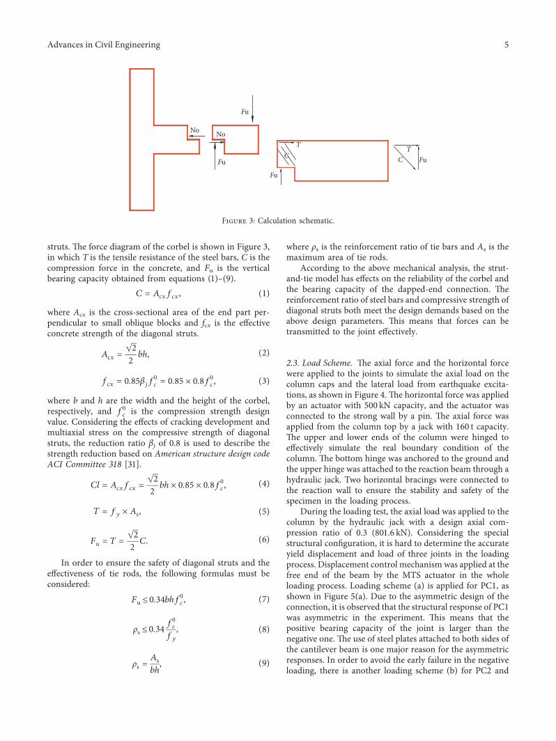
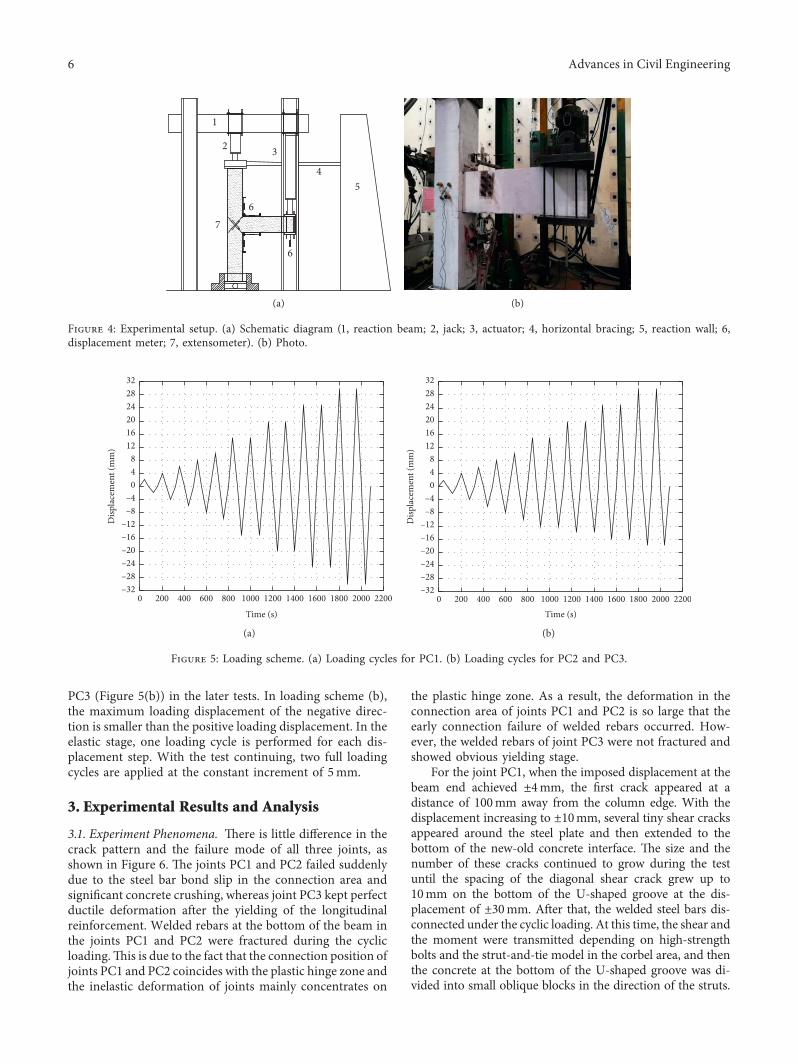
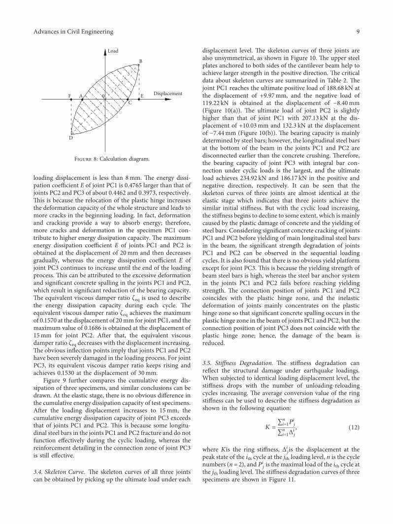
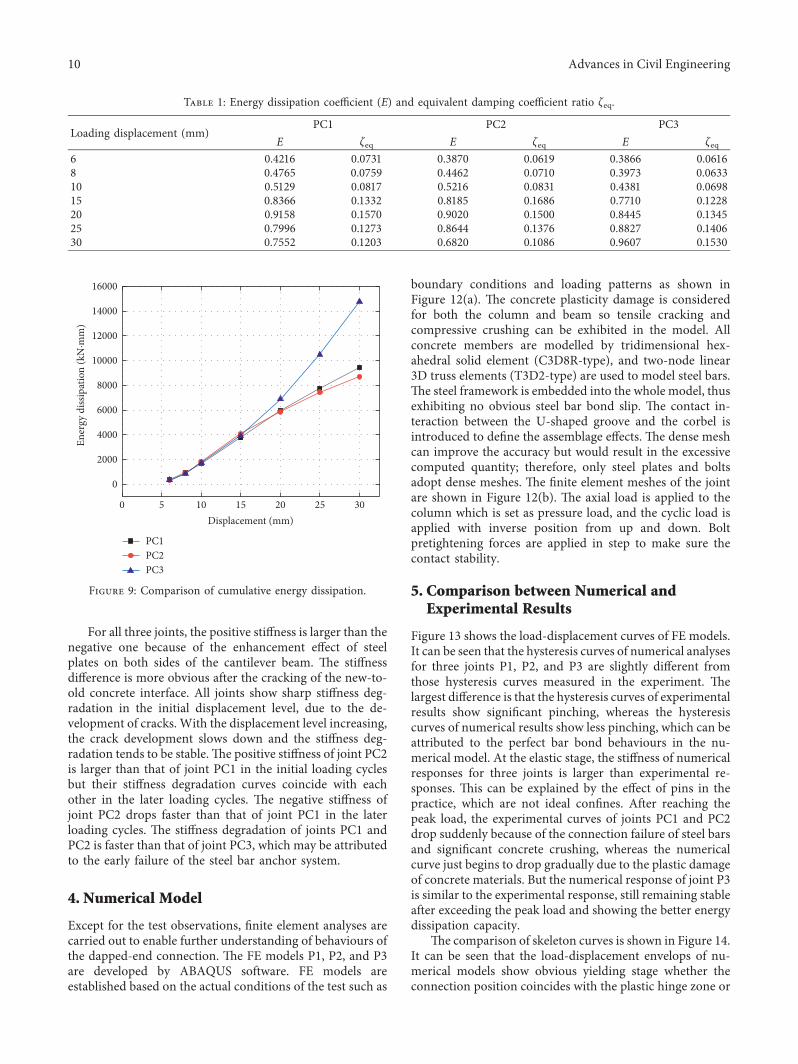
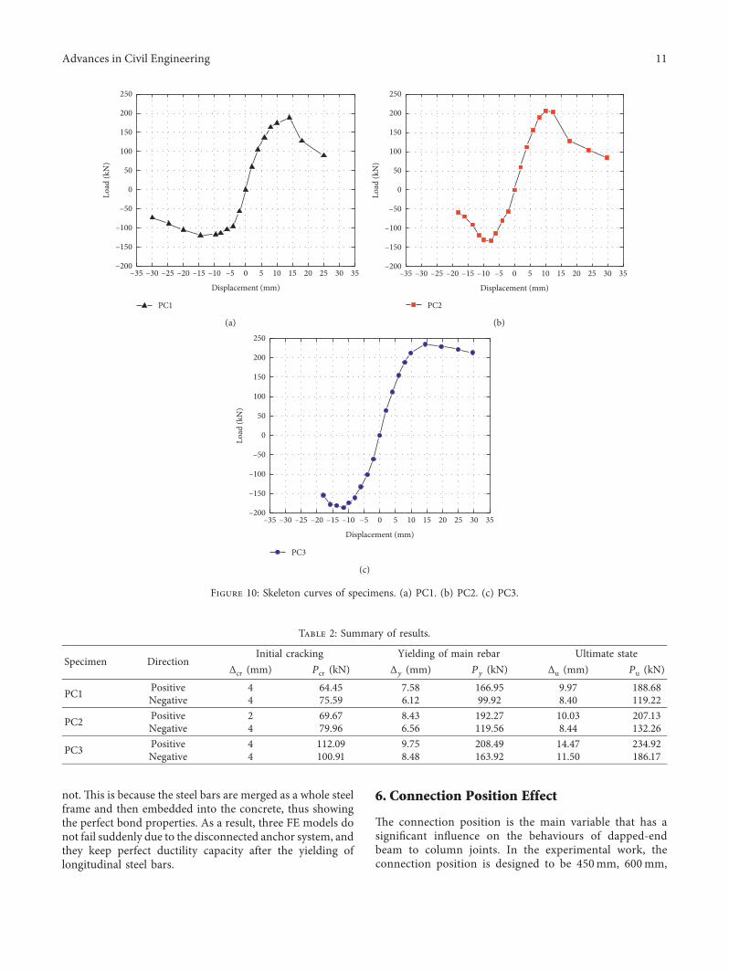
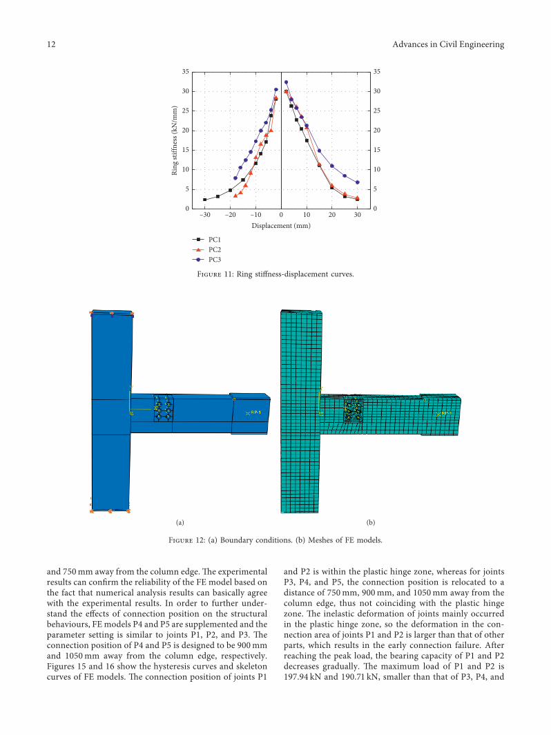
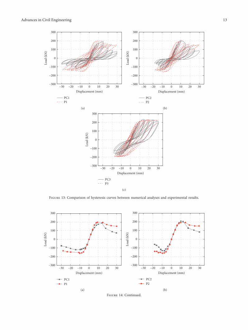
PC1P1
ndash300
ndash200
ndash100
0
100
200
300
Load
(kN
)
ndash20 ndash10 0 10 20 30ndash30Displacement (mm)
(a)
PC2P2
ndash300
ndash200
ndash100
0
100
200
300
Load
(kN
)
ndash20 ndash10 0 10 20 30ndash30Displacement (mm)
(b)
PC3P3
ndash300
ndash200
ndash100
0
100
200
300
Load
(kN
)
ndash20 ndash10 0 10 20 30ndash30Displacement (mm)
(c)
Figure 13 Comparison of hysteresis curves between numerical analyses and experimental results
PC1P1
ndash300
ndash200
ndash100
0
100
200
300
Load
(kN
)
ndash20 ndash10 0 10 20 30ndash30Displacement (mm)
(a)
PC2P2
ndash300
ndash200
ndash100
0
100
200
300
Load
(kN
)
ndash20 ndash10 0 10 20 30ndash30Displacement (mm)
(b)
Figure 14 Continued
Advances in Civil Engineering 13
PC3P3
ndash300
ndash200
ndash100
0
100
200
300
Load
(kN
)ndash20 ndash10 0 10 20 30ndash30
Displacement (mm)
(c)
Figure 14 Comparison of skeleton curves between numerical analyses and experimental results
P1
ndash300
ndash200
ndash100
0
100
200
300
Load
(kN
)
ndash20 ndash10 0 10 20 30ndash30Displacement (mm)
(a)
P2
ndash300
ndash200
ndash100
0
100
200
300Lo
ad (k
N)
ndash20 ndash10 0 10 20 30ndash30Displacement (mm)
(b)
P3
ndash20 ndash10 0 10 20 30ndash30Displacement (mm)
ndash300
ndash200
ndash100
0
100
200
300
Load
(kN
)
(c)
P4
ndash300
ndash200
ndash100
0
100
200
300
Load
(kN
)
ndash20 ndash10 0 10 20 30ndash30Displacement (mm)
(d)
Figure 15 Continued
14 Advances in Civil Engineering
P5 Both the hysteresis curves of P1 and P2 exhibit sig-nificant pinching in the cyclic loading which reveals thatmore significant bar bond slip and concrete crushing ap-pear in the joints P1 and P2 As for joints P3 P4 and P5 theconnection position is far away from the plastic hinge zone)ey show similar cyclic responses and the spindle-shapedhysteresis loops reveal that joints P3 P4 and P5 have goodenergy dissipation capacity With the connection movingaway from the plastic hinge zone the peak load of joints P3P4 and P5 is 23106 kN 25195 kN and 27742 kN re-spectively )is occurs due to the fact that the connectionposition does not coincide with the inherent plastic hingezone and the connection position of joints P4 and P5 is alsonot in the midspan of the beam As a result the bearingcapacity of joints P4 and P5 is slightly larger than that of P3
7 Conclusions
In this paper a new type of dapped-end beam to columnconnection is proposed which can provide integrity for thejoint and help to achieve the strong-column weak-beam andstrong-joint weak member failure mechanism )e quasi-static tests were carried out to analyze the influence of theconnection location on structural responses and mechanicalproperties Based on the test results FE analyses were carriedout to further understand behaviours of the dapped-endconnection )e major conclusions obtained are as follows
Comparing the failure mode of three specimens in thetest the damage was mainly concentrated in the connectionarea )is means that the connection is the weakest part inthe whole structural system Because the connection isconstructed away from the beam to column junction theplastic hinge is relocated from the column edge to beamspan which could effectively protect the joint core areaDuring the whole loading process there were few cracks inthe joint core area and the column so strong-joint weak-component and strong-column weak-beam principles canbe achieved After the new-old concrete interface crackingthe high-strength bolts and the strut-to-tie model were usedto act as force transfer mechanism)e bolts performed verywell in the whole loading process and provided good frictionand tight force for joints after the disconnection of longi-tudinal steel bars of PC1 and PC2
)e positive bearing capacity of three test specimens waslarger than that of the negative bearing capacity which can beattributed to the strengthening method (two steel plates onboth sides of the U-shaped groove))e bearing capacity andthe energy dissipation capacity of PC3 had more advantagesthan that of PC1 and PC2 In fact the plastic hinge of precastjoints is formed at a distance of about 10ndash13 times theheight of the beam away from the column edge )ereforethe plastic hinge zone of PC1 and PC2 is relocated to theconnection area the weakest part of the beam However theplastic hinge zone of PC3 is positioned in the area away from
P5
ndash300
ndash200
ndash100
0
100
200
300
Load
(kN
)ndash20 ndash10 0 10 20 30ndash30
Displacement (mm)
(e)
Figure 15 Hysteresis curves of numerical models
P1P2P3
P4P5
ndash20 ndash10 0 10 20 30ndash30Displacement (mm)
ndash300
ndash200
ndash100
0
100
200
300
Load
(kN
)
Figure 16 Skeleton curves of numerical models
Advances in Civil Engineering 15
the connection part As a result the plastic hinge rotation ofPC1 and PC2 was larger than that of PC3 which resulted inthe excessive deformation of the beam and the large strengthreduction
From the comparison between the finite element analysisresults and the experimental results it is found that thenumerical results can agree with experimental results butlittle difference can be observed in the specimens P1 and P2which can be explained by the effects of steel bar bond slip atthe bottom of the beam )is means that the overall reli-ability of numerical models can be verified
In order to further study the effects of the connectionposition on the structural behaviours FE models P4 and P5were supplemented based on the comparison results betweenexperimental responses and numerical analyses It is found thecyclic response of P3 P4 and P5 was similar but the bearingcapacity of P4 and P5 was larger )is can be attributed toeffects of connection position which neither coincides withthe plastic hinge zone nor coincides with the midspan part
When the connection is constructed in the beam-col-umn junction joints would not only be subjected to largeamounts of internal forces but also have difficulties inconstruction technology due to the heavily congested re-inforcement in the joint core area However relocating theconnection to the beam span can achieve the minimalamount of forces and deal with worry about the constructionquality Also the connection relocation can help to restraindiagonal cracking in the joint and achieve beam hingemechanism )e major inelastic deformation appears in theconnection area and the plastic hinge zone so that thestrong-joint weak-component and strong-column weak-beam mechanisms can be achieved
Data Availability
)e data used to support the findings of the study are in-cluded in the article
Conflicts of Interest
)e authors declare there are no conflicts of interest re-garding the publication of the paper
Acknowledgments
)e authors are grateful for the financial support providedby the National Natural Science Foundation of China (nos51578159 51678158 51878181 and 51608128) the Programfor New Century Excellent Talents at Fujian ProvinceUniversity (2016 no 83016017) the Cooperative Project ofFujian Province Colleges and Universities (no 2016H6011)the Natural Science Foundation of Fujian Province (no2018J01773) and the Cooperative Leading Project of FujianProvince Colleges and Universities (no 2017H0016)
References
[1] H Wang E M Marino P Pan H Liu and X Nie ldquoEx-perimental study of a novel precast prestressed reinforced
concrete beam-to-column jointrdquo Engineering Structuresvol 156 pp 68ndash81 2018
[2] G Santarsiero and A Masi ldquoSeismic performance of RCbeam-column joints retrofitted with steel dissipation jacketsrdquoEngineering Structures vol 85 pp 95ndash106 2015
[3] H Parastesh I Hajirasouliha and R Ramezani ldquoA newductile moment-resisting connection for precast concreteframes in seismic regions an experimental investigationrdquoEngineering Structures vol 70 pp 144ndash157 2014
[4] J I Resreepo and P Robert ldquoDesign of connections ofearthquake resisting precast reinforced concrete perimeterframesrdquo PCI Journal vol 40 no 5 pp 68ndash76 1995
[5] M J N Priestley and J R Tao ldquoSeismic response of precastprestressed concrete frames with partially debonded ten-donsrdquo PCI Journal vol 38 no 1 pp 58ndash69 1993
[6] M J N Priestley and G A Macrae ldquoSeismic tests of precastbeam-to-column joint subassemblages with unbonded ten-donsrdquo PCI Journal vol 41 no 1 pp 64ndash81 1996
[7] M Priestley S Sritharan J R Conley and S S PampaninldquoPreliminary results and conclusions from the press five storyprecast concrete test buildingrdquo PCI Journal vol 44 no 6pp 42ndash66 1999
[8] B G Morgen and Y C Kurama ldquoSeismic Design offriction-damped precast concrete frame structuresrdquoJournal of Structural Engineering vol 133 no 11pp 1501ndash1511 2007
[9] X Lu Y Cui J Liu and W Gao ldquoShaking table test andnumerical simulation of a 12-scale self-centering reinforcedconcrete framerdquo Earthquake Engineering amp Structural Dy-namics vol 44 no 12 pp 1899ndash1917 2015
[10] F Sarti T Smith S Pampanin et al ldquoExperimental andanalytical study of replaceable buckling-restrained fused-type(BRF) mild steel dissipatersrdquo in Proceedings of the NewZealand Society for Earthquake Engineering AnnualConference Wellington New Zealand April 2013
[11] D Guan Z Guo Q Xiao and Y Zheng ldquoExperimental studyof a new beam-to-column connection for precast concreteframes under reversal cyclic loadingrdquo Advances in StructuralEngineering vol 19 no 3 pp 529ndash545 2016
[12] H J Im H G Park and T S Eom ldquoCyclic loading test forreinforced-concrete-emulated beam-column connection ofprecast concrete moment framerdquo ACI Structural Journalvol 110 no 1 pp 115ndash126 2013
[13] S H Kim J H Moon and L H Lee ldquoAn experimental studyof the structural behaviour on the precast concrete beam-column interior joint with splice type reinforcing barsrdquoJournal of the Architectural Institute of Korea Structure ampConstruction vol 20 no 10 pp 53ndash61 2004
[14] H K Chio Y C Chio and C S Chio ldquoDevelopment andtesting of precast concrete beam-to-column connectionsrdquoEngineering Structures vol 56 pp 1820ndash1835 2013
[15] S Pampanin C Christopoulos and T Chen ldquoDevelopmentand validation of a metallic haunch seismic retrofit solutionfor existing under-designed RC frame buildingsrdquo EarthquakeEngineering vol 16 no 1 pp 21ndash42 2006
[16] A Pimanmas and P Chaimahawan ldquoShear strength of beam-column joint with enlarged joint areardquo Engineering Structuresvol 32 no 9 pp 2529ndash2545 2010
[17] T S Eom H G Park H J Hwang et al ldquoPlastic hingerelocation methods for emulative PC beam-column con-nectionsrdquo Journal of Structural Engineering vol 142 no 2pp 1ndash13 2016
[18] C-C Chen C-C Lin and C-H Lin ldquoDuctile momentconnections used in steel column-tree moment-resisting
16 Advances in Civil Engineering
framesrdquo Journal of Constructional Steel Research vol 62no 8 pp 793ndash801 2006
[19] O Arowojolu A Ibrahim M K Rahman M Al-Osta andA H Al-Gadhib ldquoPlastic hinge relocation in reinforcedconcrete beam-column joint using carbon fiber-reinforcedpolymerrdquo Advances in Structural Engineering vol 22 no 14pp 2951ndash2965 2019
[20] J H Khoo B Li and W K Yip ldquoTests on precast concreteframes with connections constructed away from columnfacesrdquo ACI Structural Journal vol 103 no 1 pp 18ndash27 2006
[21] A A Astaneh Seismic Design of Steel Column-Tree Moment-Resisting Frames Structural Steel Educational CouncilMoraga CA USA 1997
[22] D D Joshi and P V Patel ldquoExperimental study of precast dryconnections constructed away from beam-column junctionunder progressive collapse scenariordquo Asian Journal of CivilEngineering vol 20 no 2 pp 209ndash222 2019
[23] C W French O Amu and C Tarzikhan ldquoConnectionsbetween precast elements-failure outside connection regionrdquoJournal of Structural Engineering vol 115 no 2 pp 316ndash3401989
[24] C W French M Hafner and V Jayashankar ldquoConnectionsbetween precast elements-failure within connection regionrdquoJournal of Structural Engineering vol 115 no 12 pp 3171ndash3192 1989
[25] M Savoia N Buratti and L Vincenzi ldquoDamage and collapsesin industrial precast buildings after the 2012 Emilia earth-quakerdquo Engineering Structures vol 137 pp 162ndash180 2017
[26] C E Chalioris and K E Bantilas ldquoShear strength of rein-forced concrete beam-column joints with crossed inclinedbarsrdquo Engineering Structures vol 140 pp 241ndash255 2017
[27] F Faleschini L Hofer M A Zanini M dalla Benetta andC Pellegrino ldquoExperimental behavior of beam-column jointsmade with EAF concrete under cyclic loadingrdquo EngineeringStructures vol 139 pp 81ndash95 2017
[28] R Park and D K Bull ldquoSeismic resistance of frames incor-porating precast prestressed concrete beam shellsrdquo PCIJournal vol 31 no 4 pp 54ndash93 1986
[29] China Architecture Design Institute 15G310-1sim2 Construc-tion of Assembled Concrete Connection Joints China PlanningPress Beijing China 2015 in Chinese
[30] China Architecture Design Institute JGJ 1-2014 TechnicalSpecification for Assembled Concrete Structure China Ar-chitecture and Building Press Beijing China 2014 inChinese
[31] ACI Committee318 Building Code Requirements for Struc-tural Concrete (ACI 318-02) and Commentary (ACI 318R-02)American Concrete Institute Farmington Hills MI USA2001
[32] China Academy of Building Research Test Code for Earth-quake Resistant Building JGJT101-2015 China Architectureand Building Press Beijing China 2015 in Chinese
Advances in Civil Engineering 17
International Journal of
AerospaceEngineeringHindawiwwwhindawicom Volume 2018
RoboticsJournal of
Hindawiwwwhindawicom Volume 2018
Hindawiwwwhindawicom Volume 2018
Active and Passive Electronic Components
VLSI Design
Hindawiwwwhindawicom Volume 2018
Hindawiwwwhindawicom Volume 2018
Shock and Vibration
Hindawiwwwhindawicom Volume 2018
Civil EngineeringAdvances in
Acoustics and VibrationAdvances in
Hindawiwwwhindawicom Volume 2018
Hindawiwwwhindawicom Volume 2018
Electrical and Computer Engineering
Journal of
Advances inOptoElectronics
Hindawiwwwhindawicom
Volume 2018
Hindawi Publishing Corporation httpwwwhindawicom Volume 2013Hindawiwwwhindawicom
The Scientific World Journal
Volume 2018
Control Scienceand Engineering
Journal of
Hindawiwwwhindawicom Volume 2018
Hindawiwwwhindawicom
Journal ofEngineeringVolume 2018
SensorsJournal of
Hindawiwwwhindawicom Volume 2018
International Journal of
RotatingMachinery
Hindawiwwwhindawicom Volume 2018
Modelling ampSimulationin EngineeringHindawiwwwhindawicom Volume 2018
Hindawiwwwhindawicom Volume 2018
Chemical EngineeringInternational Journal of Antennas and
Propagation
International Journal of
Hindawiwwwhindawicom Volume 2018
Hindawiwwwhindawicom Volume 2018
Navigation and Observation
International Journal of
Hindawi
wwwhindawicom Volume 2018
Advances in
Multimedia
Submit your manuscripts atwwwhindawicom

International Journal of
AerospaceEngineeringHindawiwwwhindawicom Volume 2018
RoboticsJournal of
Hindawiwwwhindawicom Volume 2018
Hindawiwwwhindawicom Volume 2018
Active and Passive Electronic Components
VLSI Design
Hindawiwwwhindawicom Volume 2018
Hindawiwwwhindawicom Volume 2018
Shock and Vibration
Hindawiwwwhindawicom Volume 2018
Civil EngineeringAdvances in
Acoustics and VibrationAdvances in
Hindawiwwwhindawicom Volume 2018
Hindawiwwwhindawicom Volume 2018
Electrical and Computer Engineering
Journal of
Advances inOptoElectronics
Hindawiwwwhindawicom
Volume 2018
Hindawi Publishing Corporation httpwwwhindawicom Volume 2013Hindawiwwwhindawicom
The Scientific World Journal
Volume 2018
Control Scienceand Engineering
Journal of
Hindawiwwwhindawicom Volume 2018
Hindawiwwwhindawicom
Journal ofEngineeringVolume 2018
SensorsJournal of
Hindawiwwwhindawicom Volume 2018
International Journal of
RotatingMachinery
Hindawiwwwhindawicom Volume 2018
Modelling ampSimulationin EngineeringHindawiwwwhindawicom Volume 2018
Hindawiwwwhindawicom Volume 2018
Chemical EngineeringInternational Journal of Antennas and
Propagation
International Journal of
Hindawiwwwhindawicom Volume 2018
Hindawiwwwhindawicom Volume 2018
Navigation and Observation
International Journal of
Hindawi
wwwhindawicom Volume 2018
Advances in
Multimedia
Submit your manuscripts atwwwhindawicom