experimental study on optimisation of the burning …agronomy.emu.ee/vol122/2014_2_21_b5.pdf499...
TRANSCRIPT

499
Agronomy Research 12(2), 499–510, 2014
Experimental study on optimisation of the burning process in a
small scale pellet boiler due to air supply improvement
V. Kirsanovs*, A. Žandeckis, I. Veidenbergs, I. Blumbergs, M. Gedrovičs and D. Blumberga
Riga Technical University, Institute of Energy Systems and Environment, Kronvalda
blvd. 1, Riga, LV-1010 Latvia; *Correspondence: [email protected]
Abstract. The specific weight of biomass and pellets in thermal energy production has recently
started to increase rapidly. The continually growing price of fossil fuels and European Union
requirements to increase the share of renewable energy in thermal energy production are the main
reasons of the biomass specific weight increase. Unfortunately, Latvia uses only a small part of
the country's existing biomass potential for the time being. A growth of the amount of biomass
utilisation for energy production can be foreseen in the future, because such type of energy
production has a number of advantages, one of which is the lesser amount of emissions that arise
during the combustion process. However, the amount of emissions that arise during the
combustion of wood pellets can get lower due to optimisation of the combustion process. Air
supply is one of the main factors which have effect on the heat loss, boiler efficiency, and
emissions levels.
The main goal of this study is to optimise the pellet combustion process in a small scale pellet
boiler due to the air supply improvement. Experimental research of the combustion process of a
pellet boiler with nominal capacity 25 kW was carried out during the work. First at all, the effect
of changes in the amount of air supplied to the boiler combustion process was determined. Then,
approbation of two methods for combustion process improvement was made.
The first method was based on flame dissipation, but the second method included the opposite
method – flame concentrating. However, the main task of both methods applied was to improve
the process of mixing air and fuel. It was important to reduce the rate of air supplied, too. Four
different gratings were used for dissipation of the flame. Cylinders without and with a spiral for
flow swirl were used for flame concentration. The results of the study show that both methods,
in general, have a positive impact on the combustion process.
Key words: pellet boiler, air supply, flame dissipation, flame concentrating.
Nomenclature
C Carbon content of test fuel (as fired basis), % of mass
CO Carbon monoxide content in dry flue gases, % of volume
H Hydrogen content of test fuel (as fired basis), % of mass
NOx Nitric oxides content in dry flue gases, % of volume
O2 Oxygen content of dry flue gases, % of volume
PM Dust content of dry flue gases, % of volume
Tfg Temperature of flue gas, °C

500
INTRODUCTION
Combustion process is a complicated process where exothermic chemical reaction
between the fuel and the oxidant happens and some amount of the heat gets free. The
emission from the combustion process can be divided into two groups – unburned
pollutants and pollutants that are produced by combustion. CO, hydrocarbons,
polycyclic aromatic hydrocarbons, and tar form the unburned pollutants. Ash, particulate
matter, different nitrogen, and sulphur emissions make the second group. The amount of
the emission from the first group can be decreased if optimal combustion parameters are
organised (Khan et al., 2009). It is important to minimize the amount of CO in flue gas
to have high combustion efficiency. A specific condition must be organised in the pellet
boiler furnace to reduce the amount of CO (Hansen et al., 2009).
Nowadays, utilisation of the renewable energy from agro biomass for heat
production is becoming more and more popular in the world and, especially, in the
Northeast European countries (Mikkola & Ahokas, 2011; Beloborodko et al., 2013).
Biomass has high potential, because it is an environmentally friendly heat production
method with low amount of harmful emission (Jasinskas et al., 2011). Pellet is one of
the most popular kinds of agro biomass. There is a wide range of heating devices
available for pellet combustion.
Pellet combustion efficiency varies highly for different pellet boilers. Combustion
process efficiency in a pellet boiler can vary highly and depends on many factors. Pellet
boiler construction is one of the main parameters which have a dominant effect on the
combustion process. There are three main burner types available for pellet boilers –
underfed, horizontally fed, and top fed burners. Each of the burner types has some
specific characteristic and differences in the air supply and ash removal (Haapa-Aho et
al., 2011). In the study done by Verma et al. (2011a), a pellet boiler with different burner
types was tested. The results show that top fed boilers have higher CO concentrations
and lower efficiencies. The properties of the pellets that are used have an important role
on the combustion process (Verma et al., 2012). The fuel with high ash content has a
negative effect on the air supply and combustion process in general (Stahl & Wikström,
2009). The ash content has an impact on the dust content in flue gas (State of the art …). There are pellets with different properties available in Latvia, thus it is important to
check pellet quality (Kirsanovs et al., 2012).
Air supply has one of the dominant roles on the combustion process in a pellet
boiler. Air supply must be organized in such a way so as to reach a qualitative air and
fuel mixing process. Air must be left in the burner and furnace for a sufficient time to
achieve complete combustion. The amount of CO largely depends on the air supply
organisation (Johanssona et al., 2004). The amount of air supply affects the temperature
in the furnace, but temperature in the furnace influences all chemical reactions and
emission formatting. A study done by Verma et al. (2011b) shows that CO has an effect
on the amount of dust in flue gas. The higher the concentration of CO, the higher the
amount of the particulate matter in flue gas. The losses due to unburned combustibles in
flue gas depend on the dust content. The work done by Fernandes & Casta (2011) presents
a similar connection between CO and the dust content in flue gas. The results also show
that the amount of emissions depends on the boiler capacity. The closer the boiler
capacity is to nominal, the lower amount of emissions.

501
There are different methods to improve the combustion process in a pellet boiler
and some of them are based on air supply optimisation. Firstly, the optimal amount of
oxygen in flue gas must be determined. This optimal value can vary depending on the
boiler’s technological properties. If air supply is too high, the amount of CO increases.
Heat losses with outlet gases grow up too, and this is the main problem. Flue gas flow
rises as well. The heat transfer to water goes down, because the time during which the
hot gas is placed in the heat exchanger decreases (Loo et al., 2008). Nowadays, lambda
sondes have become more and more popular for oxygen concentration regulation in flue
gas. A study done by L. Carvalho (2008) shows the advantages of lambda sondes. The
experimental research was done using different boilers with and without lambda sondes.
There are other methods for combustion process control (Biomass combustion …, 2008; Haapa-aho et al., 2011).
Air staging is one of the commonly used methods to improve the combustion
process. Primary air was used for lighting and fuel drying, but secondary air was used to
burn out the combustible volatiles. Sometimes tertiary air was used as well. The required
amount of air in different parts of a boiler furnace can be organised if air staging is used
(Eskilsson et al., 2004). It is important to calculate the optimal ratio between primary
and secondary air supply to reduce the amount of emissions and increase combustion
efficiency (Žandeckis et al., 2013a). The location of secondary air and distance from primary air injection and the burner have important roles as well (Chaney et al., 2012).
There are many other studies where the advantages, main details, and specific features
of the air staging utilisation are described (Nussbaumer et al., 2003; Klason & Bai, 2007;
Liu et al., 2013).
Different pellet boiler burner design modifications can be used for combustion
process improvement and emission reduction. The main part of the goal of design
optimisation is to make air and fuel mix better. One of such methods is continual or
periodical fuel mixing. Different technological solutions exist. A study done by L.
Terrazzano et al. describes one of such burner design improvements (Terrazzano et al.).
METHODS AND MATERIALS
Description of the experimental stand
To achieve the goal of the research, a set of experiments were conducted using an
experimental stand which is intended for biomass boiler testing according to the standard
LVS EN 303-5 ‘Heating boilers - Part 5: Heating boilers for solid fuels, manually and
automatically stocked, nominal heat output of up to 300 kW – Terminology,
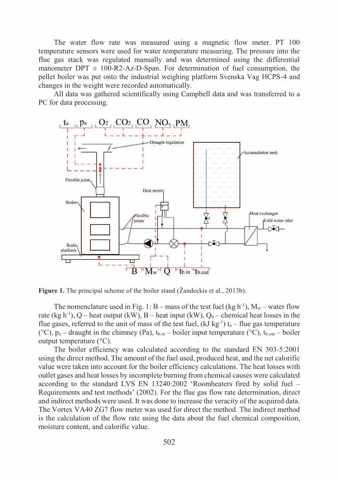
requirements, testing and marking’ (2012). The experimental stand is shown in Fig. 1.
The laboratory stand consisted of a 25 kW pellet boiler, monitoring equipment, a heat
accumulation tank, and a heat exchanger for boiler cooling.
For determination of flue gas chemical composition (NOx, CO, O2), the flue gas
analyser Testo 350XL was used. All concentrations were calculated under equal
conditions – at 10% of O2. Flue gas temperature, chemical composition, amount of dust
content in flue gas flow rate, chimney draught, fuel consumption, and thermal
performance of the boiler were monitored during the test. The K-type thermocouples
were used for the flue gas measuring.
502
The water flow rate was measured using a magnetic flow meter. PT 100
temperature sensors were used for water temperature measuring. The pressure into the
flue gas stack was regulated manually and was determined using the differential
manometer DPT ± 100-R2-Az-D-Span. For determination of fuel consumption, the
pellet boiler was put onto the industrial weighing platform Svenska Vag HCPS-4 and
changes in the weight were recorded automatically.
All data was gathered scientifically using Campbell data and was transferred to a
PC for data processing.
Figure 1. The principal scheme of the boiler stand (Žandeckis et al., 2013b).
The nomenclature used in Fig. 1: B – mass of the test fuel (kg h-1), Mw – water flow
rate (kg h-1), Q – heat output (kW), B – heat input (kW), Qb – chemical heat losses in the
flue gases, referred to the unit of mass of the test fuel, (kJ kg-1) ta – flue gas temperature
(°C), pa – draught in the chimney (Pa), tb.in – boiler input temperature (°C), tb.out – boiler
output temperature (°C). The boiler efficiency was calculated according to the standard EN 303-5:2001
using the direct method. The amount of the fuel used, produced heat, and the net calorific
value were taken into account for the boiler efficiency calculations. The heat losses with
outlet gases and heat losses by incomplete burning from chemical causes were calculated
according to the standard LVS EN 13240:2002 ‘Roomheaters fired by solid fuel –
Requirements and test methods’ (2002). For the flue gas flow rate determination, direct
and indirect methods were used. It was done to increase the veracity of the acquired data.
The Vortex VA40 ZG7 flow meter was used for direct the method. The indirect method
is the calculation of the flow rate using the data about the fuel chemical composition,
moisture content, and calorific value.

503
Description of the pellet boiler
The experiments were done using a
25 kW pellet boiler (see Fig. 2). The
burning process happens in the automatic
regime, the amount of pellets supplied and
the control of on/off sequences is the
function of the water temperature in the
boiler. Pellets from a container next to the
boiler are fed through a horizontal screw
type conveyor into a vertical, bottom fed
burner. The amount of the fuel supply was
constant for each test. The required amount
of combustion air was supplied with a fan
which was controlled by manually
changing the ON/OFF intervals of the air
blower. The amount of air supplied was
different to get different values of oxygen
concentration in the flue gas in the range
from 5% to 13%.
Figure 2. The pellet boiler Grandeg
GD_BIO 25.
Description of the fuel used for tests
Three different types of pellets were used for combustion tests. It was done to make
three series of combustion test with changed oxygen concentrations in the flue gas in the
range from 5% to 13%, and to increase the veracity of the acquired results. The physical
and chemical parameters of the pellets used for the tests are described in the Table XX.
The laboratory analysis was based on the methodology given in the CEN/TS standards,
see Table 1.
Table 1. The chemical and physical parameters of the pellets
Parameter Pellet A Pellet B Pellet C Method
Ash content, % 1.23 1.39 0.56 CEN/TS 14775 (EN, 2009)
Moisture content, % 6.71 11.84 8.56 CEN/TS 14774-3 (EN, 2009)
Net calorific value, MJ kg-1 17.7 16.4 17.4 CEN/TS 14918 (EN, 2009)
Gross calorific value, MJ kg-1 20.5 20.2 20.5 CEN/TS 14918 (EN, 2009)
C, % 45.7 43.2 44.8
H, % 5.79 5.47 5.67
Description of the methods for flame dissipation and concentration
A grate made of steel pipes with outside diameter 2.4 cm and wall thickness
2.2. mm was used for flame dissipation (see Fig. 3). In general, the construction was
made of the more than 90 tubes. The length of the tubes was 12 cm. The diameter of the
grate was about 22–23 cm. The height of the construction could be regulated with legs.
The grate was installed over the boiler burner and the flame that reached the bottom part

504
of the grate dissipated and went through pipes. The resistance of flue gas grew and the
process of air and volatiles blending was improved.
Figure 3. The grate for flame dissipation.
The second method to improve the combustion process was based on the opposite
method. A steel cylinder with a spiral for flow swirl was used for flame concentration
(see Fig. 4). The diameter of the cylinder was 18 cm and the height 30 cm. The cylinder
was installed over the burner and the flame went through it. An increase of the reaction
time between oxygen and volatiles was reached. It promoted a more complete
combustion process.
Figure 4. The cylinder for flame concentrating with a spiral for flow swirl.

505
RESULTS
Oxygen concentration changes the influence on the combustion process
The results of the tests carried out during the research show that changing the
oxygen concentration in flue gases from 5 to 13%, changes the flue gas temperature from
125°C to 170 °C (see Fig. 5). The flue gas temperature grows with oxygen concentration
increase. NOx concentration also grows, but not so sharply. The minimum amount of CO
is 30–50 ppm calculated under normal conditions with the oxygen concentrations of the
flue gas of 6–7%. The amount of CO was up to 25 times higher in the flue gas with
oxygen concentration 13%. The heat losses with outlet gases average from 5% to 14%
depending on the oxygen concentration in flue gases. The heat losses by incomplete
burning from chemical causes were significantly lower – only 0.1% with the oxygen
concentration of exhaust gas of 6–7% and 1.5% with high concentrations of oxygen
when the CO concentration in flue gas is high. The heat losses with outlet gases and by
incomplete burning from chemical causes have a dominant effect on the combustion
efficiency. Boiler efficiency varies in the range of 76 to 90%. The maximum efficiency
was established at the oxygen concentration of the flue gas of 6.5%.
Figure 5. The influence of changes in oxygen concentration on the combustion process.
Fig. 6 presents the changes of the flue gas velocity depending on the oxygen content
in the flue gas. The flue gas velocity was determined directly using a flow meter and an
indirect method was used too. The flue gas velocity was measured in a chimney with a
diameter of 16 cm. The results show that the calculated data was similar to the measured
data. The flue gas velocity increases sharply from 0.7 m s-1 at the oxygen concentration
0
30
60
90
120
150
180
210
0
200
400
600
800
1000
1200
1400
5,0 6,4 7,1 9,0 11,1 13,1
Oxygen, %
CO NOx temperature
CO, ppm (10% O2) NOx, ppm (10% O2); temperature, °C
0
300
600
900
1200
1500
75%
80%
85%
90%
95%
100%
5,0 6,4 7,1 9,0 11,1 13,1
Oxygen
efektivitāte jauda CO
CO, ppm (10% O2)Efficiency, %; capacity, 5 (in regard to nominal)
0,0%
0,2%
0,4%
0,6%
0,8%
1,0%
1,2%
1,4%
1,6%
0%
2%
4%
6%
8%
10%
12%
14%
16%
5,0 6,4 7,1 9,0 11,1 13,1
Oxygen, %
heat losses with outlet gases, %
heat losses by incomplete burning from chemical causes, %
Heat losses with outlet gases, % Heat losses by incomplete burning from chemical causes, %

506
of exhaust gas of 5% to 1.4 m s-1 at the oxygen concentration of exhaust gas of 13%. An
increase in flue gas velocity has a negative impact on combustion efficiency, because
the time during which the hot gas is in the heat exchanger decreases.
Figure 6. The flue gas velocity depending on oxygen content.
Data verification using a different fuel
Two additional series of tests were made using pellet B and pellet C to ensure that
the acquired results were not accidental and to increase the veracity of the data. The
received data about flue gas temperature, CO concentration, heat losses, dust content,
and total efficiency show similar results in general (see Fig. 7). The flue gas temperature
using pellet A was a little bit higher, but the reason for this was that pellet A has higher
calorific value. The amount of CO using pellet B was slightly higher and therefore the
heat losses by incomplete burning from chemical causes were higher too. The main
reason for this can be explained considering that pellet B has higher ash content. The
heat losses with outlet gases were higher with pellet A, because the flue gas temperature
was higher using this pellet. The efficiency in all three test series was similar. The dust
content in flue gas was determined using pellets A and B. The results of the utilisation
of different pellets were similar as well. The dust content was minimal at the oxygen
concentration of the flue gas of 6.5%, but higher at the oxygen concentration of 13%.
These results prove that CO concentration has an important role on particulate matter.
0,0
0,2
0,4
0,6
0,8
1,0
1,2
1,4
1,6
5 5,8 7,2 9,3 11,2 13,4
Oxygen, %
not direct direct
Flue gas speed, m/s

507
Figure 7. The influence of oxygen concentration changes on the combustion process used with
different types of the fuel.
Air supply optimisation. Flame dissipation and concentration
The tests with flame dissipation and concentration were carried out using pellet A;
therefore the results from the first testing series were used as reference data to determine
the effect of both methods. The results show that both approbation methods have a
positive effect (see Fig. 8). The biggest CO emission value decrease was achieved using
the flame concentration method. An especially high decrease was achieved at a high
oxygen concentration. The temperature drops by 10°C at a low oxygen concentration
and by 20 °C at a high concentration were achieved using the concentration method as
well. The temperature decrease promotes the heat losses with outlet gases to go down
too, but the CO concentration drop affects the decrease of heat losses by incomplete
burning from chemical causes. An efficiency rise was obtained using both methods, but
comparing the two methods, the biggest effect belongs to the flame concentration
method, especially at a high temperature.
R² = 0,556
80
100
120
140
160
180
3 5 7 9 11 13 15
Oxygen, %
Pellet A Pellet B Pellet C
Temperature, °C
R² = 0,8573
0
200
400
600
800
1000
1200
1400
1600
3 5 7 9 11 13 15
Oxygen, %
Pellet A Pellet B Pellet C
CO, ppm (10% O2)
R² = 0,9992
0%
5%
10%
15%
3 5 7 9 11 13 15
Oxygen, %
Pellet A Pellet B Pellet C
Heat losses with outlet gases, %
R² = 0,9442
0,0%
0,5%
1,0%
3 5 7 9 11 13 15Oxygen, %
Pellet A Pellet B Pellet C
Heat losses by incomplete burning from chemical causes, %

508
Figure 8. The effect of flame dissipation and concentration on the combustion process.
CONCLUSIONS
Experimental studies showed that air supply and oxygen concentration changes in
flue gas have an important role in the combustion process. The minimum amount of CO
and the highest efficiency of the boiler were achieved at the concentration of oxygen in
the flue gas of 6–7%. Increasing or decreasing the concentration of oxygen in the flue
gases promotes growth of the CO concentration and a decrease in the efficiency of the
pellet boiler or vice versa.
The largest heat loss formed with outlet gases – an average from 5% to 14%
depending on the oxygen concentration in the flue gases. The rise of the temperature
during the increase in the oxygen concentration is the main reason of high heat losses
with outlet gases. Heat loss due to mechanically incomplete combustion is generally
higher at a high concentration of oxygen in the flue gas. The main reason for this is the
flue gas velocity increase.
0
100
200
300
400
500
600
700
800
900
3 5 7 9 11 13 15
Oxygen, %
reference data concentrating concentrating
CO, ppm (10% O2)
80
100
120
140
160
3 5 7 9 11 13 15
Oxygen, %
reference data concentrating concentrating
Temperature, °C
0%
5%
10%
15%
3 5 7 9 11 13 15
Oxygen, %
reference data concentrating concentrating
Heat losses with outlet gases, %
-1%
1%
2%
3 5 7 9 11 13 15Oxygen, %
reference data concentrating concentrating
Heat losses by incomplete burning from chemical causes, %
75%
80%
85%
90%
95%
3 5 7 9 11 13 15
Oxygen, %
reference data concentrating concentrating
Efficiency, %

509
It was determined that the flue gas flow rate increases from 0.68 m s-1 at low
concentrations of oxygen in the flue gas to 1.35 m s-1 at the oxygen content in the flue
gas of 13%. The air and fuel mixing process deteriorates with an increase in the flue gas
flow. This is evidenced by a growth of the amount of CO at high oxygen content.
An increase in the flue gas velocity promotes a decrease in the time spent by the
flue gas in the heat exchanger. Therefore, the smaller the amount of heat transfers from
the flue gas to water, which circulates through the boiler. This is evidenced by reduction
of the efficiency of the boiler and the flue gas temperature rise with increasing the
amount of oxygen in the flue gas.
Two methods for the boiler combustion process improvement and better air and
fuel mixing were validated: flame dissipation and concentration. If we compare the two
methods, concentration of the flame shows better results. A CO reduction of about 20 to
40 ppm was achieved at low concentrations of oxygen and 170 to 240 ppm at high
concentrations of oxygen in the flue gas utilisation. The largest boiler efficiency
improvement was achieved by using a cylinder with a spiral for flow swirl. The boiler
efficiency increased by around 2% at low concentration of oxygen in exhaust gases and
around 4% at high oxygen content. The efficiency improvement was achieved thanks to
better air and fuel mixing and flue gas flow rate reduction, due to fuel combustion time
increase, improved boiler heat exchange process, and decrease of the flue gas
temperature.
REFERENCES
Beloborodko, A., Klavina, K., Romagnoli, F., Kenga, K., Rosa, M. & Blumberga, D. 2013. Study
on availability of herbaceous resources for production of solid biomass fuels in Latvia.
Agronomy research 11, 283–294.
Biomass combustion in Europe: Overwiev on technologies and regulations. Final report. 2008.
New York State Energy Research and Development Authority (NYSERDA), –97.
Carvalho, L., Lundgren, J., Wopienka, E. & Ohman, M. 2008. Challenges in small-scale
combustion of agricultural biomass fuels. International Journal on Energy for a Clean
Environment 9, 127–142.
Chaney, J., Liu, H. & Li, J. 2012. An overview of CFD modelling of small-scale fixed-bed
biomass pellet boilers with preliminary results from a simplified approach. Energy
Conversion and Management 63, 149–156.
EN 14775:2009 ‘Solid biofuels – Determination of ash content’. European Committee for
Standardization.
EN 14774-3:2009 ‘Solid biofuels – Determination of moisture content – Oven dry method – Part
3: Moisture in general analysis sample’. European Committee for Standardization. EN 14918:2009 ‘Solid biofuels – Determination of calorific value’. European Committee for
Standardization.
Eskilsson, D., Ronnback, M., Samuelsson, J. & Tullin, C. 2004. Optimisation of efficiency and
emissions in pellet burners. Biomass and Bioenergy 27, 541–546.
Fernandes, U. & Costa, M. 2011. Particle emissions from a domestic pellets-fired boiler. Fuel
Processing Technology 103, 51–56.
Haapa-Aho, J., Korpela, T., Björkqvist, T., Hrdlička, J., Plaček, V., Vrána, S. & Šulc, B. 2011.
Continuous control issues concerning operation improvement of small-scale biomass
boilers. 18th IFAC world conference in Milan.
Haapa-Aho, J. 2011. Combustions improvement of small-scale pellet boiler by continuous
control. Master of Science Thesis, Tampere University of technology, –87.

510
Hansen, T.M., Rosentoft Jein, A. & Hayes, S. 2009. English Handbook for Wood. Pellet
Combustion. – Great Britain: National Energy Foundation.
Jasinskas, A., Ulozevičiūte, I., Šakalauskas, A. & Puskunigis, M. 2011 Determination of energy
plant chopping quality and emissions while burning chaff. Agronomy research 9, 49–61.
Johanssona, L., Leckner, B., Gustavsson, L., Cooper, D. & Tullin, C., Potter, A. 2004. Emission
characteristics of modern and old-type residential boilers fired with wood logs and wood
pellets. Atmospheric Environment 38, 4183–4195.
Khan, A.A. de Jong, W. & Jansens, P.J. 2009. Biomass combustion in fluidized bed boilers:
Potential problems and remedies. Fuel Processing Technology 90, 21–50.
Kirsanovs, V., Timma, L., Žandeckis, A. & Romagnoli, F. 2012. The quality of pellets available
on the market in Latvia: classification according EN 14961 requirements. Environmental
and climate technologies 8, 36–41.
Klason, T. & Bai, X.S. 2007. Computational study of the combustion process and NO formation
in a small-scale wood pellet furnace. Fuel 86, 1465–1474.
Liu, H., Chaney, J., Li, J. & Sun, C. 2013. Control of NOx emissions of a domestic/small-scale
biomass pellet boiler by air staging. Fuel 103 792–798.
Loo, S. & Koppejan, J. 2008. The Handbook of Biomass Combustion and Co-firing. Great
Britain: Erthscan, – 442.LVS EN 13240:2002 ‘Roomheaters fired by solid fuel –
Requirements and test methods’. LVS EN 303-5:2012 ‘Heating boilers – Part 5: Heating boilers for solid fuels, manually and
automatically stocked, nominal heat output of up to 500 kW – Terminology, requirements,
testing and marking’. Mikkola, H. & Ahokas, J. 2011. Renewable energy from agro biomass. Agronomy research 9,
159–164.
Nussbaumer, T. 2003. Combustion and co-combustion of biomasas: fundamentals, technologies,
and primary measures for emission reduction. Energy & Fuels 17, 1510–1521.
Stahl, M. & Wikström, F. 2009. Swedish perspective on wood fuel pellets for household heating:
A modified standard for pellets could reduce end-user problems. Biomass and Bioenergy
33, 803–809.
State of the art of small-scale biomass combustion in boilers. Prof. Ingwald Obernberger.
Presentation. Austria.
Terrazzano, L., Allouis, C., Beretta, F., Pagliara, R. & Martino, G. Optimization of Combustion
Performances of Pellet Burners. Napoli.
Verma, V.K., Bram, S., Delattin, F., Laha, P., Vandendael, I., Hubin, A. & De Ruyck, J. 2012.
Agro-pellets for domestic heating boilers: Standard laboratory and real life performance.
Applied Energy 90, 17–23.
Verma, V.K., Bram, S., Gauthier, G. & De Ruyck, J. 2011b. Evaluation of the performance of a
multi-fuel domestic boiler with respect to the existing European standard and quality labels:
Part-1. Biomass and Bioenergy 35, 80–89.
Verma, V.K. Bram, S., Vandendael, I., Laha, P., Hubin, A. & De Ruyck, J. 2011b. Residential
pellet boilers in Belgium: Standard laboratory and real life performance with respect to
European standard and quality labels. Applied Energy 88, 2628–2634.
Žandeckis, A., Kirsanovs, V., Dzikēvičs, M., Blumberga, D. 2013a. Experimental study on the
optimisation of staged air supply in the retort pellet boiler. Agronomy research 11, 381–389.
Žandeckis, A., Timma, L., Rochas, C., Rošā, M. & Blumberga, D. 2013b. Solar and pellet
combisystem for an apartment buildings. Heat losses and efficiency improvements of the
pellet boiler. Applied Energy 101, 244–252.