f note:when specifying ordering grates referto“choosing ... · pdf filef note:when...
TRANSCRIPT
266
9T
RE
NC
HC
AS
TIN
GS
FO U N D RYN E E N A H
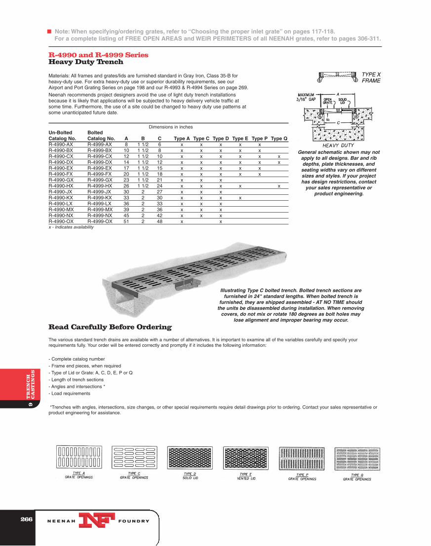
R-4990 and R-4999 SeriesHeavy Duty Trench
Materials: All frames and grates/lids are furnished standard in Gray Iron, Class 35-B forheavy-duty use. For extra heavy-duty use or superior durability requirements, see ourAirport and Port Grating Series on page 198 and our R-4993 & R-4994 Series on page 269.
Neenah recommends project designers avoid the use of light duty trench installationsbecause it is likely that applications will be subjected to heavy delivery vehicle traffic atsome time. Furthermore, the use of a site could be changed to heavy duty use patterns atsome unanticipated future date.
Dimensions in inchesUn-Bolted BoltedCatalog No. Catalog No. A B C Type A Type C Type D Type E Type P Type QR-4990-AX R-4999-AX 8 1 1/2 6 x x x x xR-4990-BX R-4999-BX 10 1 1/2 8 x x x x xR-4990-CX R-4999-CX 12 1 1/2 10 x x x x x xR-4990-DX R-4999-DX 14 1 1/2 12 x x x x x xR-4990-EX R-4999-EX 17 1 1/2 15 x x x x xR-4990-FX R-4999-FX 20 1 1/2 18 x x x x xR-4990-GX R-4999-GX 23 1 1/2 21 x x xR-4990-HX R-4999-HX 26 1 1/2 24 x x x x xR-4990-JX R-4999-JX 30 2 27 x x xR-4990-KX R-4999-KX 33 2 30 x x x xR-4990-LX R-4999-LX 36 2 33 x x xR-4990-MX R-4999-MX 39 2 36 x x xR-4990-NX R-4999-NX 45 2 42 x x xR-4990-OX R-4999-OX 51 2 48 x xx - Indicates availability
Read Carefully Before Ordering
The various standard trench drains are available with a number of alternatives. It is important to examine all of the variables carefully and specify yourrequirements fully. Your order will be entered correctly and promptly if it includes the following information:
- Complete catalog number
- Frame end pieces, when required
- Type of Lid or Grate: A, C, D, E, P or Q
- Length of trench sections
- Angles and intersections *
- Load requirements
*Trenches with angles, intersections, size changes, or other special requirements require detail drawings prior to ordering. Contact your sales representative orproduct engineering for assistance.
Illustrating Type C bolted trench. Bolted trench sections arefurnished in 24" standard lengths. When bolted trench is
furnished, they are shipped assembled - AT NO TIME shouldthe units be disassembled during installation. When removing
covers, do not mix or rotate 180 degrees as bolt holes maylose alignment and improper bearing may occur.
General schematic shown may notapply to all designs. Bar and ribdepths, plate thicknesses, andseating widths vary on differentsizes and styles. If your projecthas design restrictions, contact
your sales representative orproduct engineering.
F Note: When specifying/ordering grates, refer to “Choosing the proper inlet grate” on pages 117-118.For a complete listing of FREE OPEN AREAS and WEIR PERIMETERS of all NEENAH grates, refer to pages 306-311.
267
F Note: The suggested forming procedures shown in this catalog are general suggestions to qualified professionals,and may not be appropriate for every installation.
9T
RE
NC
HC
AS
TIN
GS
FO U N D RYN E E N A H
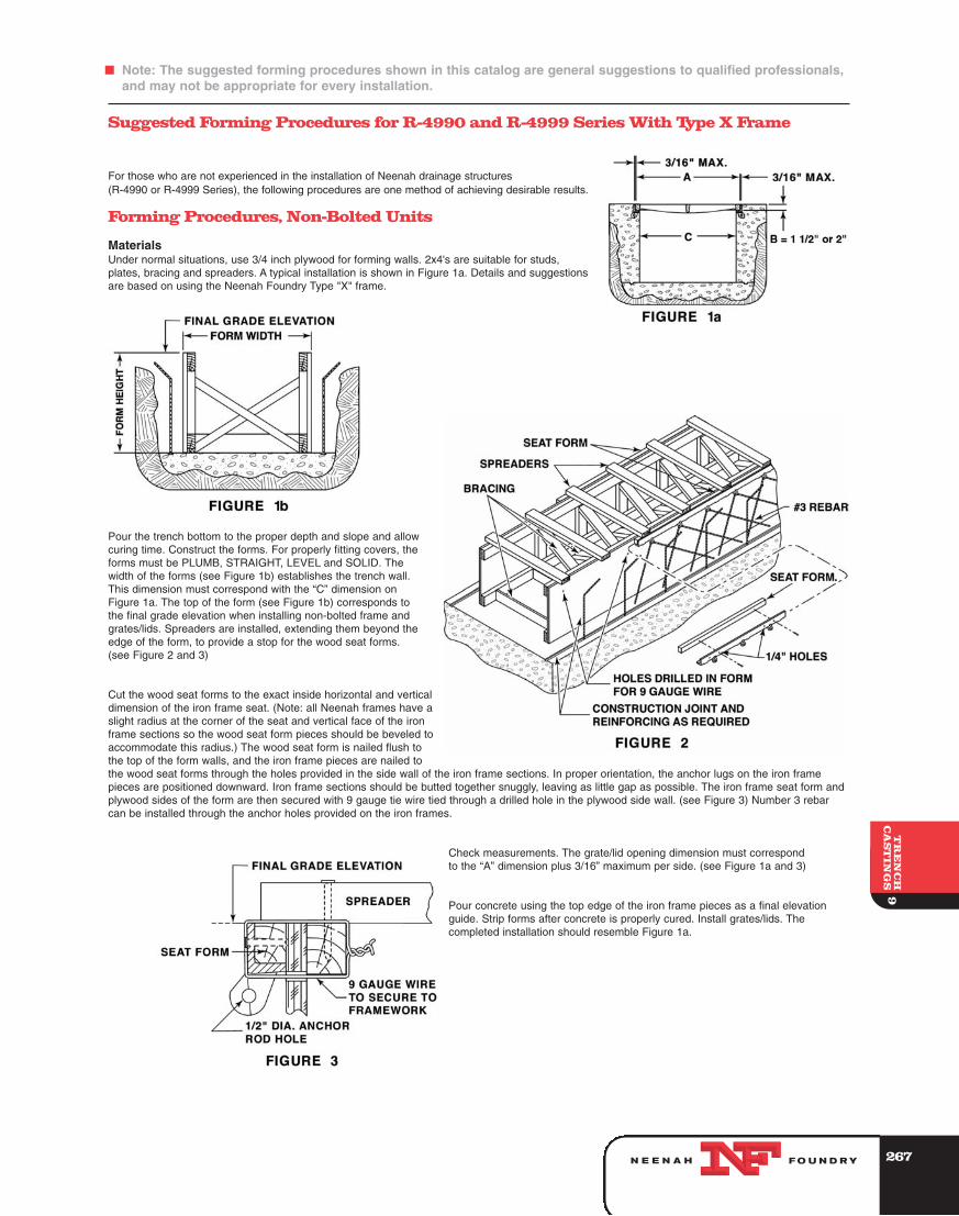
Suggested Forming Procedures for R-4990 and R-4999 Series With Type X Frame
For those who are not experienced in the installation of Neenah drainage structures(R-4990 or R-4999 Series), the following procedures are one method of achieving desirable results.
Forming Procedures, Non-Bolted Units
MaterialsUnder normal situations, use 3/4 inch plywood for forming walls. 2x4's are suitable for studs,plates, bracing and spreaders. A typical installation is shown in Figure 1a. Details and suggestionsare based on using the Neenah Foundry Type "X" frame.
Pour the trench bottom to the proper depth and slope and allowcuring time. Construct the forms. For properly fitting covers, theforms must be PLUMB, STRAIGHT, LEVEL and SOLID. Thewidth of the forms (see Figure 1b) establishes the trench wall.This dimension must correspond with the “C” dimension onFigure 1a. The top of the form (see Figure 1b) corresponds tothe final grade elevation when installing non-bolted frame andgrates/lids. Spreaders are installed, extending them beyond theedge of the form, to provide a stop for the wood seat forms.(see Figure 2 and 3)
Cut the wood seat forms to the exact inside horizontal and verticaldimension of the iron frame seat. (Note: all Neenah frames have aslight radius at the corner of the seat and vertical face of the ironframe sections so the wood seat form pieces should be beveled toaccommodate this radius.) The wood seat form is nailed flush tothe top of the form walls, and the iron frame pieces are nailed tothe wood seat forms through the holes provided in the side wall of the iron frame sections. In proper orientation, the anchor lugs on the iron framepieces are positioned downward. Iron frame sections should be butted together snuggly, leaving as little gap as possible. The iron frame seat form andplywood sides of the form are then secured with 9 gauge tie wire tied through a drilled hole in the plywood side wall. (see Figure 3) Number 3 rebarcan be installed through the anchor holes provided on the iron frames.
Check measurements. The grate/lid opening dimension must correspondto the “A” dimension plus 3/16” maximum per side. (see Figure 1a and 3)
Pour concrete using the top edge of the iron frame pieces as a final elevationguide. Strip forms after concrete is properly cured. Install grates/lids. Thecompleted installation should resemble Figure 1a.
268
F Note: The suggested forming procedures shown in this catalog are general suggestions to qualified professionals,and may not be appropriate for every installation.
9T
RE
NC
HC
AS
TIN
GS
FO U N D RYN E E N A H
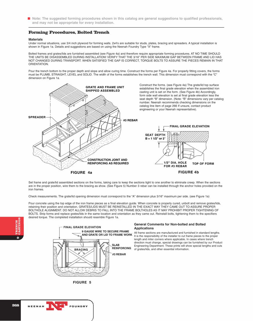
Forming Procedures, Bolted Trench
MaterialsUnder normal situations, use 3/4 inch plywood for forming walls. 2x4's are suitable for studs, plates, bracing and spreaders. A typical installation isshown in Figure 1a. Details and suggestions are based on using the Neenah Foundry Type "X" frame.
Bolted frames and grates/lids are furnished assembled (see Figure 4a) and therefore require appropriate forming procedures. AT NO TIME SHOULDTHE UNITS BE DISASSEMBLED DURING INSTALLATION! VERIFY THAT THE 3/16” PER SIDE MAXIMUM GAP BETWEEN FRAME AND LID HASNOT CHANGED DURING TRANSPORT. WHEN SATISFIED THE GAP IS CORRECT, TORQUE BOLTS TO ASSURE THE PIECES REMAIN IN THATORIENTATION.
Pour the trench bottom to the proper depth and slope and allow curing time. Construct the forms per Figure 4a. For properly fitting covers, the formsmust be PLUMB, STRAIGHT, LEVEL and SOLID. The width of the forms establishes the trench wall. This dimension must correspond with the “C”dimension on Figure 1a.
Construct the forms. (see Figure 4a) The grate/lid top surfaceestablishes the final grade elevation when the assembled ironcasting unit is set on the form. (See Figure 4b) Accordingly,form side wall elevation is set at final grade elevation less theseat depth “B” dimension. (Note: “B” dimensions vary per catalognumber. Neenah recommends checking dimensions on thecatalog line item of page 266 If unsure, contact productengineering or your Neenah representative).
Set frame and grate/lid assembled sections on the forms, taking care to keep the sections tight to one another to eliminate creep. When the sectionsare in the proper position, wire them to the bracing as show. (See Figure 5) Number 3 rebar can be installed through the anchor holes provided on theiron frames.
Check measurements. The grate/lid opening dimension must correspond to the “A” dimension plus 3/16” maximum per side. (see Figure 1a)
Pour concrete using the top edge of the iron frame pieces as a final elevation guide. When concrete is properly cured, unbolt and remove grates/lids,retaining their position and orientation. GRATES/LIDS MUST BE REINSTALLED IN THE EXACT WAY THEY CAME OUT TO ASSURE PROPERBOLTHOLE ALIGNMENT. DO NOT ALLOW DEBRIS TO FALL INTO THE FRAME BOLTHOLES AS IT MAY PROHIBIT PROPER TIGHTENING OFBOLTS. Strip forms and replace grates/lids in the same location and orientation as they came out. Reinstall bolts, tightening them to the specifiersdesired torque. The completed installation should resemble Figure 1a.
General Comments for Non-bolted and BoltedApplicationsAll frame sections are manufactured and furnished in standard lengths.It is the responsibility of the installer to cut frame pieces to the properlength and miter corners where applicable. In cases where trenchdirection must change, special drawings can be furnished by our ProductEngineering Department. These prints will show special lengths and cutsof grates/lids, and other essential information.
269
F Note: The suggested forming procedures shown in this catalog are general suggestions to qualified professionals,and may not be appropriate for every installation.
9T
RE
NC
HC
AS
TIN
GS
FO U N D RYN E E N A H
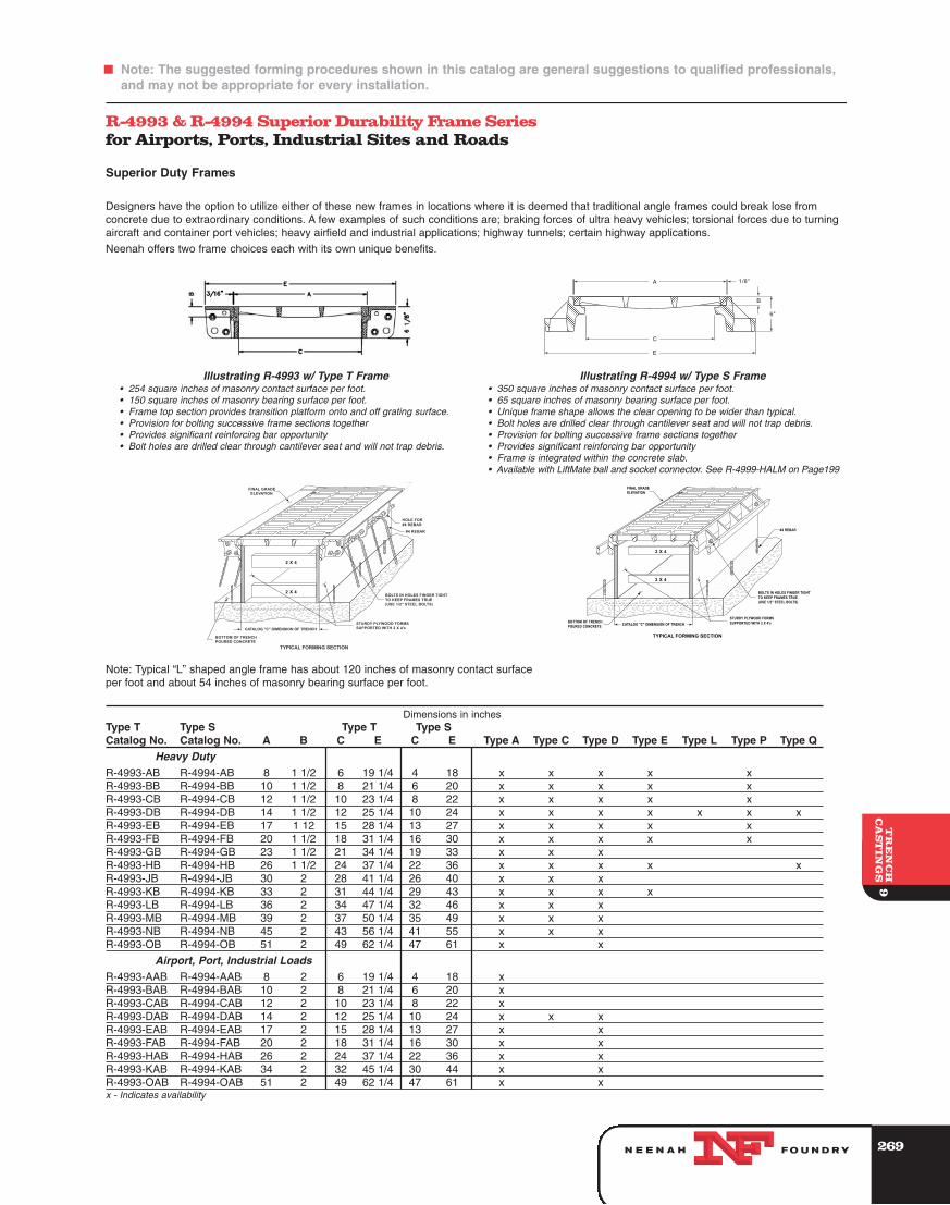
R-4993 & R-4994 Superior Durability Frame Seriesfor Airports, Ports, Industrial Sites and Roads
Superior Duty Frames
Designers have the option to utilize either of these new frames in locations where it is deemed that traditional angle frames could break lose fromconcrete due to extraordinary conditions. A few examples of such conditions are; braking forces of ultra heavy vehicles; torsional forces due to turningaircraft and container port vehicles; heavy airfield and industrial applications; highway tunnels; certain highway applications.
Neenah offers two frame choices each with its own unique benefits.
Note: Typical “L” shaped angle frame has about 120 inches of masonry contact surfaceper foot and about 54 inches of masonry bearing surface per foot.
Dimensions in inchesType T Type S Type T Type SCatalog No. Catalog No. A B C E C E Type A Type C Type D Type E Type L Type P Type Q
Heavy DutyR-4993-AB R-4994-AB 8 1 1/2 6 19 1/4 4 18 x x x x xR-4993-BB R-4994-BB 10 1 1/2 8 21 1/4 6 20 x x x x xR-4993-CB R-4994-CB 12 1 1/2 10 23 1/4 8 22 x x x x xR-4993-DB R-4994-DB 14 1 1/2 12 25 1/4 10 24 x x x x x x xR-4993-EB R-4994-EB 17 1 12 15 28 1/4 13 27 x x x x xR-4993-FB R-4994-FB 20 1 1/2 18 31 1/4 16 30 x x x x xR-4993-GB R-4994-GB 23 1 1/2 21 34 1/4 19 33 x x xR-4993-HB R-4994-HB 26 1 1/2 24 37 1/4 22 36 x x x x xR-4993-JB R-4994-JB 30 2 28 41 1/4 26 40 x x xR-4993-KB R-4994-KB 33 2 31 44 1/4 29 43 x x x xR-4993-LB R-4994-LB 36 2 34 47 1/4 32 46 x x xR-4993-MB R-4994-MB 39 2 37 50 1/4 35 49 x x xR-4993-NB R-4994-NB 45 2 43 56 1/4 41 55 x x xR-4993-OB R-4994-OB 51 2 49 62 1/4 47 61 x x
Airport, Port, Industrial LoadsR-4993-AAB R-4994-AAB 8 2 6 19 1/4 4 18 xR-4993-BAB R-4994-BAB 10 2 8 21 1/4 6 20 xR-4993-CAB R-4994-CAB 12 2 10 23 1/4 8 22 xR-4993-DAB R-4994-DAB 14 2 12 25 1/4 10 24 x x xR-4993-EAB R-4994-EAB 17 2 15 28 1/4 13 27 x xR-4993-FAB R-4994-FAB 20 2 18 31 1/4 16 30 x xR-4993-HAB R-4994-HAB 26 2 24 37 1/4 22 36 x xR-4993-KAB R-4994-KAB 34 2 32 45 1/4 30 44 x xR-4993-OAB R-4994-OAB 51 2 49 62 1/4 47 61 x xx - Indicates availability
Illustrating R-4993 w/ Type T Frame• 254 square inches of masonry contact surface per foot.• 150 square inches of masonry bearing surface per foot.• Frame top section provides transition platform onto and off grating surface.• Provision for bolting successive frame sections together• Provides significant reinforcing bar opportunity• Bolt holes are drilled clear through cantilever seat and will not trap debris.
Illustrating R-4994 w/ Type S Frame• 350 square inches of masonry contact surface per foot.• 65 square inches of masonry bearing surface per foot.• Unique frame shape allows the clear opening to be wider than typical.• Bolt holes are drilled clear through cantilever seat and will not trap debris.• Provision for bolting successive frame sections together• Provides significant reinforcing bar opportunity• Frame is integrated within the concrete slab.• Available with LiftMate ball and socket connector. See R-4999-HALM on Page199

270
F Note: The suggested forming procedures shown in this catalog are general suggestions to qualified professionals,and may not be appropriate for every installation.
9T
RE
NC
HC
AS
TIN
GS
FO U N D RYN E E N A H
Forming Procedures R-4993 & R-4994 Bolted Trench Series
Bolted frames and grates/lids are furnished assembled and therefore require different forming procedures than unbolted trenches. AT NO TIMESHOULD THE UNITES BE DISASSEMBLED DURING INSTALLATION! VERIFY THAT THE 3/16” PER SIDE MAXIMUM GAP BETWEEN FRAME ANDLID HAS NOT CHANGED DURING TRANSPORT. WHEN SATISFIED THE GAP IS CORRECT, TORQUE BOLTS TO ASSURE THE PIECES REMAININ THAT ORIENTATION.
R-4993 Forming Procedures
Follow forming procedures for bolted trench on page 268. The following exceptions apply.
• Use Figure 6 as a guide.
• Frame pieces can be bolted together making sure that bolts are only finger tight.
• Reinforcing bar can be installed per Figure 6.
R-4994 Forming Procedures
Follow forming procedures for bolted trench on page 268. The following exceptions apply.
• Use Figure 7 as a guide.
• The frame seat for the R-4994 series cantilevers over the trench opening. This requires the distance between sidewalls to be set accordingly. It thiscase, bolted assemblies are set upon the side wall forms with the contact area being the top of the form and the underside of the cantilever seat.(See Figure 6a on previous page)
• The inside distance between concrete sidewalls correspond with the CS dimension shown on page 268 of the catalog.
• Frame pieces can be bolted together making sure that bolts are only finger tight.
• Reinforcing bar can be installed per Figure 7.
Figure 6
Figure 7
271
F Note: The suggested forming procedures shown in this catalog are general suggestions to qualified professionals,and may not be appropriate for every installation.
9T
RE
NC
HC
AS
TIN
GS
FO U N D RYN E E N A H
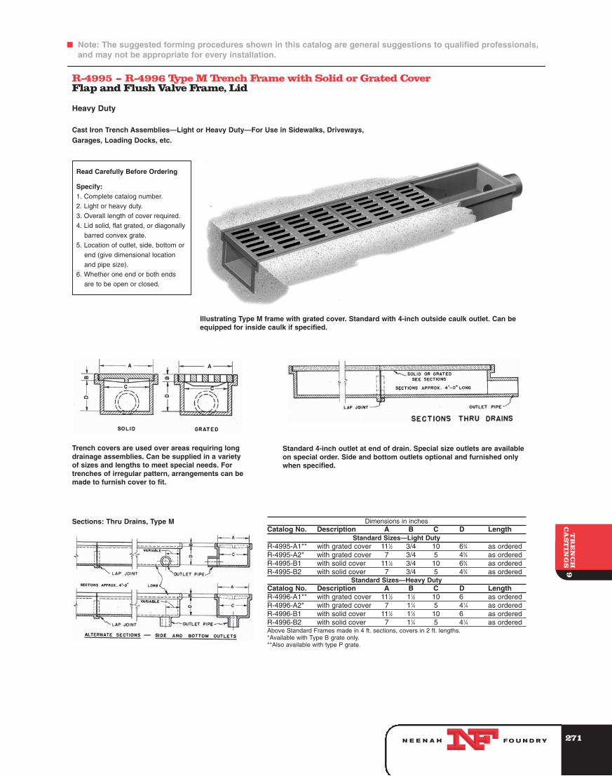
R-4995 – R-4996 Type M Trench Frame with Solid or Grated CoverFlap and Flush Valve Frame, Lid
Heavy Duty
Cast Iron Trench Assemblies—Light or Heavy Duty—For Use in Sidewalks, Driveways,Garages, Loading Docks, etc.
Read Carefully Before Ordering
Specify:1. Complete catalog number.
2. Light or heavy duty.
3. Overall length of cover required.
4. Lid solid, flat grated, or diagonally
barred convex grate.
5. Location of outlet, side, bottom or
end (give dimensional location
and pipe size).
6. Whether one end or both ends
are to be open or closed.
Trench covers are used over areas requiring longdrainage assemblies. Can be supplied in a varietyof sizes and lengths to meet special needs. Fortrenches of irregular pattern, arrangements can bemade to furnish cover to fit.
Standard 4-inch outlet at end of drain. Special size outlets are availableon special order. Side and bottom outlets optional and furnished onlywhen specified.
Illustrating Type M frame with grated cover. Standard with 4-inch outside caulk outlet. Can beequipped for inside caulk if specified.
Sections: Thru Drains, Type M Dimensions in inchesCatalog No. Description A B C D Length
Standard Sizes—Light DutyR-4995-A1** with grated cover 111⁄2 3/4 10 63⁄4 as orderedR-4995-A2* with grated cover 7 3/4 5 43⁄4 as orderedR-4995-B1 with solid cover 111⁄2 3/4 10 63⁄4 as orderedR-4995-B2 with solid cover 7 3/4 5 43⁄4 as ordered
Standard Sizes—Heavy DutyCatalog No. Description A B C D LengthR-4996-A1** with grated cover 111⁄2 11⁄2 10 6 as orderedR-4996-A2* with grated cover 7 11⁄4 5 41⁄4 as orderedR-4996-B1 with solid cover 111⁄2 11⁄2 10 6 as orderedR-4996-B2 with solid cover 7 11⁄4 5 41⁄4 as orderedAbove Standard Frames made in 4 ft. sections, covers in 2 ft. lengths.*Available with Type B grate only.**Also available with type P grate.
272
F Note: The suggested forming procedures shown in this catalog are general suggestions to qualified professionals,and may not be appropriate for every installation.
9T
RE
NC
HC
AS
TIN
GS
FO U N D RYN E E N A H
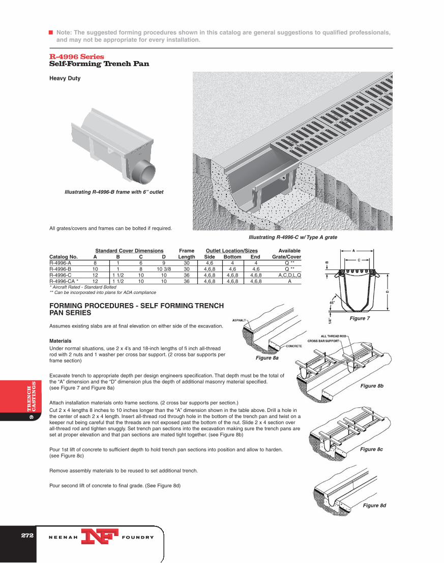
R-4996 SeriesSelf-Forming Trench Pan
Heavy Duty
All grates/covers and frames can be bolted if required.
Standard Cover Dimensions Frame Outlet Location/Sizes AvailableCatalog No. A B C D Length Side Bottom End Grate/CoverR-4996-A 8 1 6 9 30 4,6 4 4 Q **R-4996-B 10 1 8 10 3/8 30 4,6,8 4,6 4,6 Q **R-4996-C 12 1 1/2 10 10 36 4,6,8 4,6,8 4,6,8 A,C,D,L,QR-4996-CA * 12 1 1/2 10 10 36 4,6,8 4,6,8 4,6,8 A* Aircraft Rated - Standard Bolted** Can be incorporated into plans for ADA compliance
FORMING PROCEDURES - SELF FORMING TRENCHPAN SERIES
Assumes existing slabs are at final elevation on either side of the excavation.
MaterialsUnder normal situations, use 2 x 4’s and 18-inch lengths of fi inch all-threadrod with 2 nuts and 1 washer per cross bar support. (2 cross bar supports perframe section)
Excavate trench to appropriate depth per design engineers specification. That depth must be the total ofthe “A” dimension and the “D” dimension plus the depth of additional masonry material specified.(see Figure 7 and Figure 8a)
Attach installation materials onto frame sections. (2 cross bar supports per section.)
Cut 2 x 4 lengths 8 inches to 10 inches longer than the “A” dimension shown in the table above. Drill a hole inthe center of each 2 x 4 length. Insert all-thread rod through hole in the bottom of the trench pan and twist on akeeper nut being careful that the threads are not exposed past the bottom of the nut. Slide 2 x 4 section overall-thread rod and tighten snuggly. Set trench pan sections into the excavation making sure the trench pans areset at proper elevation and that pan sections are mated tight together. (see Figure 8b)
Pour 1st lift of concrete to sufficient depth to hold trench pan sections into position and allow to harden.(see Figure 8c)
Remove assembly materials to be reused to set additional trench.
Pour second lift of concrete to final grade. (See Figure 8d)
Illustrating R-4996-C w/ Type A grate
Illustrating R-4996-B frame with 6” outlet
Figure 7
Figure 8a
Figure 8b
Figure 8c
Figure 8d
273
9T
RE
NC
HC
AS
TIN
GS
FO U N D RYN E E N A H
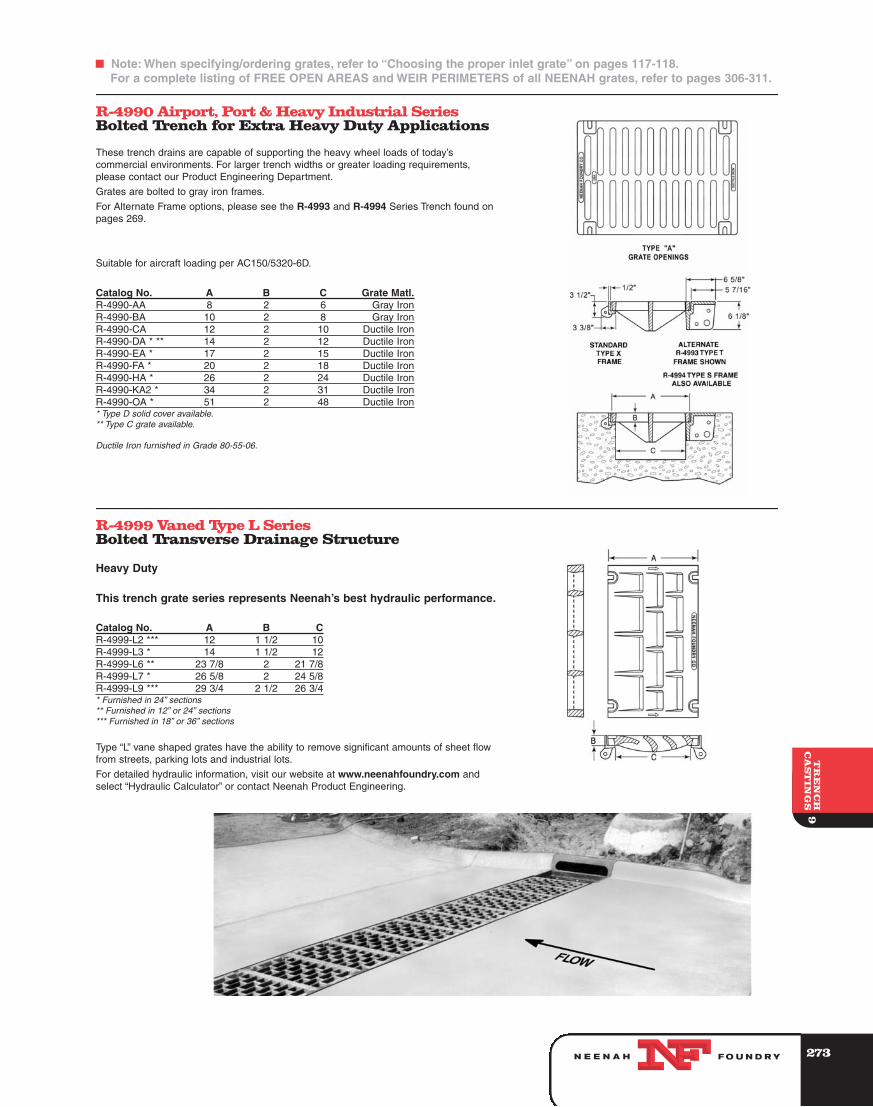
R-4990 Airport, Port & Heavy Industrial SeriesBolted Trench for Extra Heavy Duty Applications
These trench drains are capable of supporting the heavy wheel loads of today’scommercial environments. For larger trench widths or greater loading requirements,please contact our Product Engineering Department.
Grates are bolted to gray iron frames.
For Alternate Frame options, please see the R-4993 and R-4994 Series Trench found onpages 269.
Suitable for aircraft loading per AC150/5320-6D.
Catalog No. A B C Grate Matl.R-4990-AA 8 2 6 Gray IronR-4990-BA 10 2 8 Gray IronR-4990-CA 12 2 10 Ductile IronR-4990-DA * ** 14 2 12 Ductile IronR-4990-EA * 17 2 15 Ductile IronR-4990-FA * 20 2 18 Ductile IronR-4990-HA * 26 2 24 Ductile IronR-4990-KA2 * 34 2 31 Ductile IronR-4990-OA * 51 2 48 Ductile Iron* Type D solid cover available.** Type C grate available.
Ductile Iron furnished in Grade 80-55-06.
R-4999 Vaned Type L SeriesBolted Transverse Drainage Structure
Heavy Duty
This trench grate series represents Neenah’s best hydraulic performance.
Catalog No. A B CR-4999-L2 *** 12 1 1/2 10R-4999-L3 * 14 1 1/2 12R-4999-L6 ** 23 7/8 2 21 7/8R-4999-L7 * 26 5/8 2 24 5/8R-4999-L9 *** 29 3/4 2 1/2 26 3/4* Furnished in 24” sections** Furnished in 12” or 24” sections*** Furnished in 18” or 36” sections
Type “L” vane shaped grates have the ability to remove significant amounts of sheet flowfrom streets, parking lots and industrial lots.
For detailed hydraulic information, visit our website at www.neenahfoundry.com andselect “Hydraulic Calculator” or contact Neenah Product Engineering.
F Note: When specifying/ordering grates, refer to “Choosing the proper inlet grate” on pages 117-118.For a complete listing of FREE OPEN AREAS and WEIR PERIMETERS of all NEENAH grates, refer to pages 306-311.