f5 automation & orchestration - introduction documentation
TRANSCRIPT

F5 Automation & Orchestration -Introduction Documentation
Release 1.0
Hitesh Patel, Eric Chen, Nathan Pearce
February 07, 2017


Contents:
1 Lab Topology 3
2 Module 1 – REST API Basics & Device Onboarding 52.1 Lab 1.1 – Exploring the iControl REST API . . . . . . . . . . . . . . . . . . . . . . . . . . . . . . 52.2 Lab 1.2 – REST API Authentication & ‘example’ Templates . . . . . . . . . . . . . . . . . . . . . . 72.3 Lab 1.3 – Review/Set Device Settings . . . . . . . . . . . . . . . . . . . . . . . . . . . . . . . . . . 132.4 Lab 1.4 – Basic Network Connectivity . . . . . . . . . . . . . . . . . . . . . . . . . . . . . . . . . 162.5 Lab 1.5 – Build a BIG-IP Cluster . . . . . . . . . . . . . . . . . . . . . . . . . . . . . . . . . . . . 172.6 Lab 1.6 – Build a Basic LTM Config . . . . . . . . . . . . . . . . . . . . . . . . . . . . . . . . . . 242.7 Lab 1.7 – REST API Transactions . . . . . . . . . . . . . . . . . . . . . . . . . . . . . . . . . . . . 25
3 Module 2 – iWorkflow 293.1 Lab 2.1 – iWorkflow Authentication . . . . . . . . . . . . . . . . . . . . . . . . . . . . . . . . . . . 293.2 Lab 2.2 – Discover BIG-IP Devices . . . . . . . . . . . . . . . . . . . . . . . . . . . . . . . . . . . 333.3 Lab 2.3 – Create Local Connector . . . . . . . . . . . . . . . . . . . . . . . . . . . . . . . . . . . . 363.4 Lab 2.4 – Create an L4–7 Service Template & Deployment . . . . . . . . . . . . . . . . . . . . . . . 383.5 Lab 2.5 – iWorkflow REST Proxy . . . . . . . . . . . . . . . . . . . . . . . . . . . . . . . . . . . . 43
4 Module 3 - Python SDK 454.1 Lab 3.1 – create_pool.py . . . . . . . . . . . . . . . . . . . . . . . . . . . . . . . . . . . . . . . . . 464.2 Lab 3.2 – read_pool.py . . . . . . . . . . . . . . . . . . . . . . . . . . . . . . . . . . . . . . . . . . 484.3 Lab 3.3 – update_pool.py . . . . . . . . . . . . . . . . . . . . . . . . . . . . . . . . . . . . . . . . 494.4 Lab 3.4 – update_pool_member_state.py . . . . . . . . . . . . . . . . . . . . . . . . . . . . . . . . 504.5 Lab 3.5 – delete_pool.py . . . . . . . . . . . . . . . . . . . . . . . . . . . . . . . . . . . . . . . . . 514.6 Lab 3.6 – Create a Python Script . . . . . . . . . . . . . . . . . . . . . . . . . . . . . . . . . . . . . 514.7 Lab 3.7 – EXTRA CREDIT – Modify create_pool.py . . . . . . . . . . . . . . . . . . . . . . . . . 534.8 Lab 3.8 – EXTRA CREDIT – Review super_pool.py . . . . . . . . . . . . . . . . . . . . . . . . . . 53
i

ii

F5 Automation & Orchestration - Introduction Documentation, Release 1.0
Raymond’s F5 Automation & Orchestration - Introduction
Please follow the instructions provided by the instructor to start your lab and access your jump host.
Note: All work for this lab will be performed exclusively from the windows jumphost. No installation or interactionwith your local system is required.
Contents: 1

F5 Automation & Orchestration - Introduction Documentation, Release 1.0
2 Contents:

CHAPTER 1
Lab Topology
The network topology implemented for this lab is very simple. Since the focus of the lab is Control Plane programma-bility rather that Data Plane traffic flow we can keep the data plane fairly simple. The following components have beenincluded in your lab environment:
• 2 x F5 BIG-IP VE (v12.0)
• 1 x F5 iWorkflow VE (v2.0.0)
• 1 x Linux Webserver
• 1 x Windows Jumphost
The following table lists VLANS, IP Addresses and Credentials for all components:
Component VLAN: IP Address(es) CredentialsWindows Jumphost MGMT: 10.1.1.3
Internal: 10.1.10.250External: 10.1.20.250
user/user
BIG IP A MGMT: 10.1.1.4Internal: 10.1.10.1External: 10.1.20.1
root/defaultadmin/admin
BIG-IP B MGMT: 10.1.1.5Internal: 10.1.10.2External: 10.1.20.2
root/defaultadmin/admin
iWorkflow MGMT: 10.1.1.6 root/defaultadmin/admin
Linux Webserver MGMT: 10.1.1.7Internal: 10.1.10.10-13
root/default
3

F5 Automation & Orchestration - Introduction Documentation, Release 1.0
4 Chapter 1. Lab Topology

CHAPTER 2
Module 1 – REST API Basics & Device Onboarding
In this module you will learn the basic concepts required to interact with the BIG-IP iControl REST API. Additionally,you will walk through a typical Device Onboarding workflow that results in a fully functional BIG-IP Active/Standbypair. It’s important to note that this module will focus on showing an Imperative approach to automation.
Note: The Lab Deployment for this lab includes two BIG-IP devices. For most of the labs we will focus on configuringonly the BIG-IP-A device (management IP and licensing have already been completed). BIG-IP-B already has someminimal configuration loaded. In a real-world environment it would be necessary to perform Device Onboardingfunctions on ALL BIG-IP devices. We are only performing them on a single device in this lab so we are able to coverall topics in the time allotted.
Note: It’s beneficial to have GUI/SSH sessions open to BIG-IP and iWorkflow devices while going through this lab.Feel free to verify the actions taken in the lab against the GUI or SSH. You can also watch the following logs:
• BIG-IP:
– /var/log/ltm
– /var/log/restjavad.0.log
• iWorkflow:
– /var/log/restjavad.0.log
2.1 Lab 1.1 – Exploring the iControl REST API
2.1.1 Task 1 – Explore the API using the TMOS Web Interface
In this lab we will explore the API using an interface that is built-in to TMOS. This utility is useful for understandinghow TMOS objects map to the REST API. The interfaces implement full Create, Read, Update and Delete (CRUD)functionality, however, in most practical use cases it’s far easier to use this interface as a ‘Read’ tool rather than tryingto Create objects directly from it. It’s usually far easier to use TMUI or TMSH to create the object as needed and thenuse this tool to view the created object with all the correct attributes already populated.
1. Open Google Chrome and navigate to the following bookmarks: BIG-IP A GUI, BIG-IP B GUI and iWorkflowGUI. Bypass any SSL errors that appear and ensure you see the login screen for each bookmark.
5

F5 Automation & Orchestration - Introduction Documentation, Release 1.0
2. Navigate to the URL https://10.1.1.4/mgmt/toc (or click the BIG-IP A REST TOC bookmark). The ‘/mgmt/toc’path in the URL is available on all TMOS versions 11.6 or newer.
3. Authenticate to the interface using the default admin/admin credentials.
4. You will now be presented with a top-level list of various REST resources. At the top of the page there is a
search box that can be used to find items on the page. Type ‘net’ in the search box and then
click on the ‘net’ link under iControl REST Resources:
5. Find the /mgmt/tm/net/route-domain Collection and click it.
6. You will now see a listing of the Resources that are part of the route-domain(s) collection. As you can see the
default route domain of ‘0’ is listed. You can also create new objects by clicking the button. Additionally
resources can be deleted using the button or edited using the button.
7. Click the ‘0’ resource to view the attributes of route-domain 0 on the device:
Take note of the full path to the resource. Here is how the path is broken down:
/ mgmt / tm / net / route-domain / ~Common~0| Root | OC | OC | Collection | Resource
*OC=Organizing Collection
6 Chapter 2. Module 1 – REST API Basics & Device Onboarding

F5 Automation & Orchestration - Introduction Documentation, Release 1.0
2.2 Lab 1.2 – REST API Authentication & ‘example’ Templates
One of the many basic concepts related to interaction with REST API’s is how a particular consumer is authenticated tothe system. BIG-IP and iWorkflow support two types of authentication: HTTP BASIC and Token based. It’s importantto understand both of these authentication mechanisms, as consumers of the API will often make use of both typesdepending on the use case. This lab will demonstrate how to interact with both types of authentication.
2.2.1 Task 1 – HTTP BASIC Authentication
In this task we will use the Postman tool to send API requests using HTTP BASIC authentication. As its name impliesthis method of authentication encodes the user credentials via the existing BASIC authentication method provided bythe HTTP protocol. The mechanism this method uses is to insert an HTTP header named ‘Authorization’ with a valuethat is built by Base 64 encoding the string <username>:<password>. The resulting header takes this form:
Authorization: Basic YWRtaW46YWRtaW4=
It should be noted that cracking the method of authentication is TRIVIAL; as a result API calls should always beperformed using HTTPS (F5 default) rather than HTTP.
Perform the following steps to complete this task:
1. Open the Postman tool by clicking the icon of the taskbar of your Windows Jumphost
2. To assist in multi-step procedures we make heavy use of the ‘Environments’ capability in Postman. This ca-pability allows us to set various global variables that are then substituted into a request before it’s sent. Whenyou open Postman please verify that your environment is set the ‘INTRO - Automation & Orchestration Lab’environment:
3. Click the ‘Collections’ tab on the left side of the screen, expand the ‘F5 Automation & Orchestration Intro’collection on the left side of the screen, expand the ‘Lab 1.2 – API Authentication’ folder:
2.2. Lab 1.2 – REST API Authentication & ‘example’ Templates 7

F5 Automation & Orchestration - Introduction Documentation, Release 1.0
4. Click the ‘Step 1: HTTP BASIC Authentication’ item. Click the ‘Authorization’ tab and select ‘Basic Auth’ asthe Type. Fill in the username and password (admin/admin) and click the ‘Update Request’ button. Notice thatthe number of Headers in the Headers tab changed from 1 to 2. This is because Postman automatically createdthe HTTP header and updated your request to include it. Click the ‘Headers’ tab and examine the HTTP header:
5. Click the ‘Send’ button to send the request. If the request succeeds you should be presented with a listing of the/mgmt/tm/ltm Organizing Collection.
6. Update the credentials and specify an INCORRECT password. Send the request again and examine the response:
8 Chapter 2. Module 1 – REST API Basics & Device Onboarding

F5 Automation & Orchestration - Introduction Documentation, Release 1.0
2.2.2 Task 2 – Token Based Authentication
One of the disadvantages of BASIC Authentication is that credentials are sent with each and every request. This canresult in a much greater attack surface being exposed unnecessarily. As a result Token Based Authentication (TBA) ispreferred in many cases. This method only sends the credentials once, on the first request. The system then respondswith a unique token for that session and the consumer then uses that token for all subsequent requests. Both BIG-IP andiWorkflow support token-based authentication that drops down to the underlying authentication subsystems availablein TMOS. As a result the system can be configured to support external authentication providers (RADIUS, TACACS,AD, etc) and those authentication methods can flow through to the REST API. In this task we will demonstrate TBAusing the local authentication database, however, authentication to external providers is fully supported.
For more information about external authentication providers see the section titled “About external authenticationproviders with iControl REST” in the iControl REST API User Guide available at https://devcentral.f5.com
Perform the following steps to complete this task:
1. Click the ‘Step 2: Get Authentication Token’ item in the Lab 1.2 Postman Collection
2. Notice that we send a POST request to the /mgmt/shared/authn/login endpoint. Additionally, BASICAuthentication is required on the initial token request:
3. Click the ‘Body’ tab and examine the JSON that we will send to BIG-IP to provide credentials and the authen-tication provider:
4. Modify the JSON body and add the required credentials (admin/admin). Then click the ‘Send’ button.
5. Examine the response status code. If authentication succeeded and a token was generated the response will havea 200 OK status code. If the status code is 401 then check your credentials:
Successful:
•
2.2. Lab 1.2 – REST API Authentication & ‘example’ Templates 9

F5 Automation & Orchestration - Introduction Documentation, Release 1.0
Unsuccessful:
•
6. Once you receive a 200 OK status code examine the response body. The various attributes show the parametersassigned to the particular token. Find the ‘token’ attribute and copy it into your clipboard (Ctrl+c) for use in thenext step:
7. Click the ‘Step 3: Verify Authentication Works’ item in the Lab 1.2 Postman collection. Click the ‘Headers’tab and paste the token value copied above as the VALUE for the X-F5-Auth-Token header. This header isrequired to be sent on all requests when using token based authentication.
8. Click the ‘Send’ button. If your request is successful you should see a ‘200 OK’ status and a listing of the ltmOrganizing Collection.
9. We will now update your Postman environment to use this auth token for the remainder of the lab. Click theEnvironment menu in the top right of the Postman window and click ‘Manage Environments’:
10 Chapter 2. Module 1 – REST API Basics & Device Onboarding

F5 Automation & Orchestration - Introduction Documentation, Release 1.0
10. Click the ‘INTRO – Automation & Orchestration Lab’ item:
11. Update the value for big_ip_a_auth_token by Pasting (Ctrl-v) in your auth token:
12. Click the ‘Update’ button and then close the ‘Manage Environments’ window. You’re subsequent requests willnow automatically include the token.
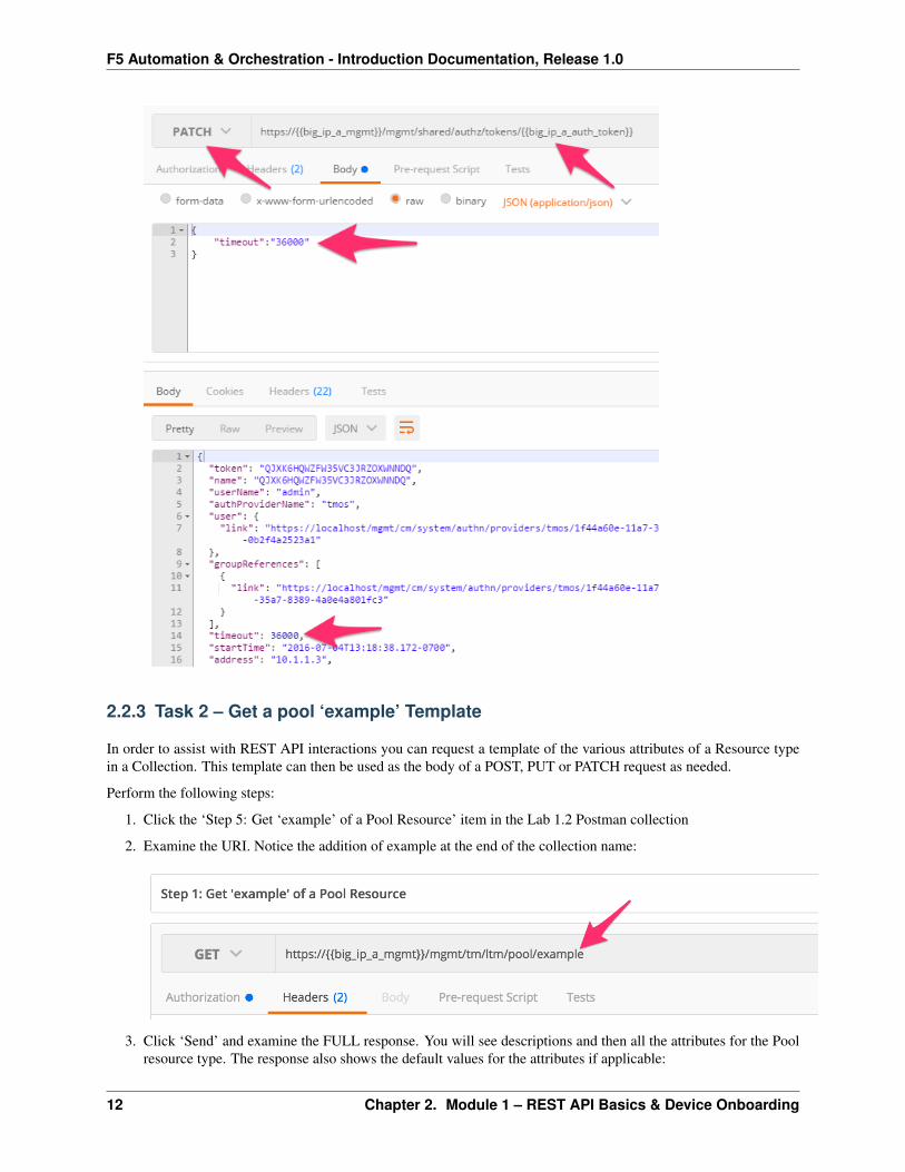
13. Click the ‘Step 4: Set Authentication Token Timeout’ item in the Lab 1.2 Postman collection. This request willPATCH your token Resource (check the URI) and update the timeout attribute so we can complete the lab easily.Examine the request type and JSON Body and then click the ‘Send’ button. Verify that the timeout has beenchanged to ‘36000’ in the response:
2.2. Lab 1.2 – REST API Authentication & ‘example’ Templates 11
F5 Automation & Orchestration - Introduction Documentation, Release 1.0
2.2.3 Task 2 – Get a pool ‘example’ Template
In order to assist with REST API interactions you can request a template of the various attributes of a Resource typein a Collection. This template can then be used as the body of a POST, PUT or PATCH request as needed.
Perform the following steps:
1. Click the ‘Step 5: Get ‘example’ of a Pool Resource’ item in the Lab 1.2 Postman collection
2. Examine the URI. Notice the addition of example at the end of the collection name:
3. Click ‘Send’ and examine the FULL response. You will see descriptions and then all the attributes for the Poolresource type. The response also shows the default values for the attributes if applicable:
12 Chapter 2. Module 1 – REST API Basics & Device Onboarding

F5 Automation & Orchestration - Introduction Documentation, Release 1.0
2.3 Lab 1.3 – Review/Set Device Settings
Your BIG-IP-A device is already licensed, so now we can focus on configuring the basic infrastructure related settingsto complete the Device Onboarding process. The remaining items include (list not exhaustive):
• Device Settings
– NTP/DNS Settings
– Remote Authentication
– Hostname
– Admin Credentials
• L1-3 Networking
– Physical Interface Settings
– L2 Connectivity (VLAN, VXLAN, etc.)
– L3 Connectivity (Self IPs, Routing, etc.)
• HA Settings
– Global Settings
* Config Sync IP
2.3. Lab 1.3 – Review/Set Device Settings 13

F5 Automation & Orchestration - Introduction Documentation, Release 1.0
* Mirroring IP
* Failover Addresses
– CMI Device Trusts
– Device Groups
– Traffic Groups
– Floating Self IPs
We will specifically cover the items in BOLD above in the following labs. It should be noted that many permutationsof the Device Onboarding process exist due to the nature of customer environments. This class is designed to teachenough information so that you can then apply the knowledge learned and help articulate and/or deliver a specificsolution for your environment.
2.3.1 Task 1 – Set Device Hostname & Disable GUI Setup Wizard
In this task we will modify the device hostname and disable the GUI Setup Wizard. The Resource that contains thesesettings is /mgmt/tm/sys/global-settings.
Perform the following steps to complete this task:
1. Expand the “Lab 1.3 – Review/Set Device Settings” folder in the Postman collection
2. Click the “Step 1: Get System Global-Settings” item. Click the ‘Send’ button and review the response body tosee what the current settings on the device are.
3. Click the “Step 2: Set System Global-Settings” item. This item uses a PATCH request to theglobal-settings resource to modify the attributes contained within it. We will update the guiSetupand hostname attribute.
• Review the JSON body and modify the ‘hostname’ attribute to set the hostname tobigip-a.f5se.local
• Also notice that we are disabling the GUI Setup Wizard as part of the same request:
4. Click the ‘Send’ button and review the response body. You should see that the attributes modified above havebeen updated. You can also GET the global-settings again to verify they have been updated.
2.3.2 Task 2 – Modify DNS/NTP Settings
Much like the previous task we can update system DNS and NTP settings by sending a PATCH request to the correctresource in the ‘sys’ Organizing Collection. The relevant Resources for this task are:
14 Chapter 2. Module 1 – REST API Basics & Device Onboarding

F5 Automation & Orchestration - Introduction Documentation, Release 1.0
URL Type/mgmt/tm/sys/dns DNS Settings/mgmt/tm/sys/ntp NTP Settings
Perform the following steps to complete this task:
1. Click the “Step 3: Get System DNS Settings” item in the collection. Click ‘Send’ and review the current settings
2. Click the “Step 4: Set System DNS Settings” item in the collection. Modify the JSON body to add a name serverwith IP ‘4.2.2.2’. Additionally add a search domain of ‘f5se.local’. You will modify a JSON array for both ofthese attributes. The format of a JSON array is: “myAttribute”: [ “item1”,”item2”,”item3”]
3. Click the ‘Send’ button and verify the requested changes were successfully implemented
4. Click the “Step 5: Get System NTP Settings” item in the collection. Click ‘Send’ and review the current settings
5. Click the “Step 6: Set System NTP Settings” item in the collection. Modify the JSON body to add a NTP serverwith hostname ‘pool.ntp.org’ to the ‘servers’ attribute (another JSON array!)
6. Click the ‘Send’ button and verify the requested changes were successfully implemented
2.3.3 Task 3 – Update default user account passwords
In this task we will update the passwords for the ‘root’ and ‘admin’ accounts. The process for updating the rootaccount is different then other system accounts due to the special nature of the root account.
To update the root account password we will use a POST to a shared REST worker at/mgmt/shared/authn/root
To update all other system accounts we will PATCH the /mgmt/auth/user/<username> Resource
Perform the following steps to change the root user password:
1. Click the “Step 7: Set root User Password” item in the collection.
2. Notice that we a performing a POST operation to a shared REST worker. Modify the JSON body to update thepassword to the value “newdefault” and click the ‘Send’ button.
3. You can verify the password was changed by opening an SSH session using PuTTY to BIG-IP-A.
4. Repeat the procedure above to change the password back to “default”
Perform the following steps to change the admin user password:
1. Click the “Step 8: Set admin User Password” item in the collection.
2.3. Lab 1.3 – Review/Set Device Settings 15

F5 Automation & Orchestration - Introduction Documentation, Release 1.0
2. Notice that we a performing a PATCH operation to admin user Resource. Modify the JSON body to update thepassword to the value “newadmin” and click the ‘Send’ button.
3. You can verify the password was changed by opening an SSH session using PuTTY to BIG-IP-A OR by logginginto TMUI in a Chrome browser tab.
4. Repeat the procedure above to change the password back to “admin”
2.4 Lab 1.4 – Basic Network Connectivity
This lab will focus on configuration of the following items:
• L1-3 Networking
– Physical Interface Settings
– L2 Connectivity (VLAN, VXLAN, etc.)
– L3 Connectivity (Self IPs, Routing, etc.)
We will specifically cover the items in BOLD above in the following labs. It should be noted that many permutationsof the Device Onboarding process exist due to the nature of customer environments. This class is designed to teachenough information so that you can then apply the knowledge learned and help articulate and/or deliver a specificsolution to your customer.
The following table lists the L2-3 network information used to configure connectivity for BIG-IP-A:
Type Name DetailsVLAN Internal Interface: 1.1
Tag: 10VLAN External Interface: 1.2
Tag: 20Self IP Self-Internal Address: 10.1.10.1/24
VLAN: InternalSelf IP Self-External Address: 10.1.20.1/24
VLAN: ExternalRoute Default Network: 0.0.0.0/0
GW: 10.1.20.254
2.4.1 Task 1 – Create VLANs
Perform the following steps to configure the VLAN objects/resources:
16 Chapter 2. Module 1 – REST API Basics & Device Onboarding

F5 Automation & Orchestration - Introduction Documentation, Release 1.0
1. Expand the “Lab 1.4 – Basic Network Connectivity” folder in the Postman collection.
2. Click the “Step 1: Create a VLAN” item in the collection. Examine the JSON body; the values for creating theInternal VLAN have already been populated.
3. Click the ‘Send’ button to create the VLAN
4. Repeat Step 1, however, this time modify the JSON body to create the External VLAN using the parameters inthe table above.
5. Click the “Step 2: Get VLANs” item in the collection. Click the ‘Send’ button to GET the VLAN collection.Examine the response to make sure both VLANs have been created.
2.4.2 Task 2 – Create Self IPs
Perform the following steps to configure the Self IP objects/resources:
1. Click the “Step 3: Create a Self IP” item in the collection. Examine the JSON body; the values for creating theSelf-Internal Self IP have already been populated.
2. Click the ‘Send’ button to create the Self IP
3. Repeat Step 1, however, this time modify the JSON body to create the Self-External Self IP using the parametersin the table above.
4. Click the “Step 4: Get Self IPs” item in the collection. Click the ‘Send’ button to GET the Self IP collection.Examine the response to make sure both Self IPs have been created.
2.4.3 Task 3 – Create Routes
Perform the following steps to configure the Route object/resource:
1. Click the “Step 5: Create a Route” item in the collection. Examine the JSON body; the values for creating theDefault Route have already been populated.
2. Click the ‘Send’ button to create the Route
3. Click the “Step 6: Get Routes” item in the collection. Click the ‘Send’ button to GET the routes collection.Examine the response to make sure the route has been created.
2.5 Lab 1.5 – Build a BIG-IP Cluster
In this lab we will build a active-standby cluster between BIG-IP-A and BIG-IP-B. As mentioned previously, to savetime, BIG-IP-B already has already been licensed and had its device level settings configured. This lab will walk youthrough creating the cluster step by step. As you will see complex operation such as this start to become less effectiveusing the Imperative model of automation. Clustering is one of the ‘transition’ points for most customers to move intothe Declarative model (if not already done) due to the need to abstract device/vendor level specifics from Automationconsumers.
The high-level procedure required to create the cluster is:
1. Rename the CMI ‘Self’ Device name to match the hostname of the Device
2. Set BIG-IP-A & BIG-IP-B CMI Parameters (Config Sync IP, Failover IPs, Mirroring IP)
3. Add BIG-IP-B as a trusted peer on BIG-IP-A
4. Check the device_trust_group Sync Group Status
2.5. Lab 1.5 – Build a BIG-IP Cluster 17

F5 Automation & Orchestration - Introduction Documentation, Release 1.0
5. Create a sync-failover Device Group
6. Check the status of the created Device Group
7. Perform initial sync of the Device Group
8. Check status (again)
9. Change the Traffic Group to use HA Order failover (not required but shown as an example)
10. Create Floating Self IPs
2.5.1 Task 1 – Rename objects and Setup CMI Global Parameters
In this task we will complete Items 1&2 from the list high-level procedure at the beginning of the lab. One of theidiosyncrasies of BIG-IP is that when you use the GUI Setup Wizard to set the hostname of the device, the wizardautomatically renames the CMI ‘Self’ device to match the hostname. Since we configured the hostname via a RESTcall earlier this action did not take place.
Perform the following steps to rename the CMI ‘Self’ device:
1. Expand the “Lab 1.5 – Build a Cluster” folder in the Postman collection
2. Click the “Step 1: Rename the CMI Self Device’ item in the collection
3. Examine the URI and JSON body. We are sending a POST request to execute the equivalent of a tmsh mv com-mand to rename the existing object to the /mgmt/tm/cm/device Collection. The name attribute specifiesthe current name of the object (the factory default name), while the target attribute specifies the new name ofthe object.
4. Click the ‘Send’ button to rename the Resource.
5. Change the request type from a POST to a GET and click ‘Send’. Examine the response to make sure the namewas changed successfully.
Perform the following steps to set CMI Device Parameters
1. Click the “Step 2: Set BIGIP-A CMI Device Parameters” item in the collection. Examine theoperation (PATCH), URI and JSON body. We will PATCH the newly renamed object (from theprevious step) and assign the Config Sync IP, Unicast Failover Address/Port and Mirroring IPs:
2. Click the ‘Send’ button and examine the response to ensure the settings were changed
18 Chapter 2. Module 1 – REST API Basics & Device Onboarding

F5 Automation & Orchestration - Introduction Documentation, Release 1.0
3. Click the “Step 3: Set BIGIP-B CMI Device Parameters” item in the collection. Examine the operation(PATCH), URI and JSON body. We will PATCH the newly renamed object (from the previous step) and as-sign the Config Sync IP, Unicast Failover Address/Port and Mirroring IPs.
EXTRA CREDIT: How is authentication to BIG-IP-B working if we never got an authentication token? (Hint:we cheated)
4. Click the ‘Send’ button and examine the response to ensure the settings were changed
2.5.2 Task 2 – Add BIG-IP-B as a Trusted Peer
The CMI subsystem relies on a PKI based device trust model to establish relationships between BIG-IP systems. Inthis task we will add BIG-IP-B as a trusted peer of BIG-IP-A. Establishing a trust relationship is automatically a bi-directional operation. As a result, when we establish the trust relationship, BIG-IP-B will automatically establish atrust relationship with BIG-IP-A. This task corresponds to items 3&4 in the high-level procedure.
Perform the following steps to complete this task:
1. Click the “Step 4: Add BIGIP-B Device to CMI Trust on BIGIP-A” item in the collection
2. Examine the operation (POST), URI and JSON body. We are using a special REST worker to add the deviceto the CMI trust. Additionally the JSON body must be specified in a very specific manner to ensure this stepcompletes successfully. To minimize the chance for error the values have been completed for you already. Youshould, however, review and understand this step fully before continuing.
3. Click the ‘Send’ button. The response for this request does NOT indicate success, only that the command isrunning.
4. To check for success we have to check the status of the Sync Group named “device_trust_group”. To do thisclick the “Step 5: Check Sync Group Status” item in the collection. This request will GET the sync status forall sync groups on the system
5. Click the ‘Send’ button and examine the response. The should indicate a color of ‘green’,that bigip-b.f5se.local is connected and ‘In Sync’ (please notify an instructor of any issue):
2.5. Lab 1.5 – Build a BIG-IP Cluster 19

F5 Automation & Orchestration - Introduction Documentation, Release 1.0
2.5.3 Task 3 – Create a sync-failover Device Group
This task will create a Device Group object that will contain the two BIG-IP systems. The type of device-group willbe a ‘sync-failover’ group, however, ‘sync-only’ groups can also be created with the same procedure but differentattribute values. This task corresponds to items 5-8 in the high-level procedure.
Perform the following steps to complete this task
1. Click the “Step 6: Create Device Group” item in the collection. Examine the request type, URL andJSON body. We will POST to the ‘/mgmt/tm/cm/device-group’ collection and create a new Resourcecalled DeviceGroup1 that includes both BIG-IP devices and is set to ‘sync-failover’ type. We are alsosetting the device-group to ‘autosync’ so manual syncing is not required when configuration changes occur:
20 Chapter 2. Module 1 – REST API Basics & Device Onboarding

F5 Automation & Orchestration - Introduction Documentation, Release 1.0
2. Click the ‘Send’ button and examine the response.
3. To check the status of the device-group we have to check the status of the underlying syncgroup on the system. Click the ‘Step 7: Check Sync Group Status’ item in the collection andclick ‘Send’. Examine the response and take note that the system is ‘Awaiting Initial Sync’:
4. We will now manually sync DeviceGroup1 to fulfill the need for the Initial Sync. Click the ‘Step 8: ManuallySync DeviceGroup1’ item in the collection. Examine the request type, URL and JSON body. We will POST thethe ‘/mgmt/tm/cm/config-sync’ worker and tell it to ‘run’ a config-sync of BIG-IP-A ‘to-group’ DeviceGroup1:
2.5. Lab 1.5 – Build a BIG-IP Cluster 21

F5 Automation & Orchestration - Introduction Documentation, Release 1.0
5. Click ‘Send’ to initiate the sync
6. Click the ‘Step 9: Check Sync Group Status’ item in the collection and click the ‘Send’ button. Examine theresponse to make sure that DeviceGroup1 is ‘In Sync’. You may have to click ‘Send’ multiple times as the syncoperation can take a while to complete.
2.5.4 Task 4 – Perform Additional Operations
The remainder of the steps show how to manipulate various common items related to the HA config. In this task wewill change the Traffic Group to use the ‘HA Order’ failover method. We will then initiate a failover and show how toview the status of the traffic-group.
Perform the following steps to complete this task:
1. Click the “Step 10: Get Traffic Group Properties” item in the collection. Examine the URL, we will GET theattributes of the ‘traffic-group-1’ resource from the traffic-group collection. Click the ‘Send’ button and reviewthe response.
2. Click the “Step 11: Change Traffic Group to use HA Order” item in the collection. Examine the request type,URL and JSON body. We will PATCH the existing resource and specify an ‘haOrder’ attribute to change thetraffic-group behavior.
3. Click the ‘Send’ button and examine the response to verify the change was successful.
4. Click the “Step 12: Get Traffic Group Failover States” item in the collection and click the‘Send’ button. Examine the response and determine which device is ‘active’ for the traffic-group:
22 Chapter 2. Module 1 – REST API Basics & Device Onboarding

F5 Automation & Orchestration - Introduction Documentation, Release 1.0
5. Click EITHER the “Step 13A” or “Step 13B” item in the collection depending on which device is ACTIVE forthe traffic group. Notice that we are sending the request to the ACTIVE device for the traffic group. Examinethe JSON body and click the ‘Send’ button.
6. Click the “Step 14: Get Traffic Group Failover States” item in the collection and clickthe ‘Send’ button. Examine the response to determine that the failover occurred properly:
2.5. Lab 1.5 – Build a BIG-IP Cluster 23

F5 Automation & Orchestration - Introduction Documentation, Release 1.0
2.5.5 Task 5 – Create Floating Self IPs
To complete the HA config we will now create a Floating Self IP on the Internal VLAN.
Perform the following steps to complete this task:
1. Click the “Step 15: Create a Floating Self IP” item in the collection. Examine the request type, URL and JSONbody. We will create a new resource in the /mgmt/tm/net/self collection named ‘Self-Internal-Floating’and an IP address of 10.1.10.3.
2. Click the ‘Send’ button and examine the response
3. Click the “Step 16: Get Self IPs” item in the collection and click ‘Send’. Examine the response and verify theSelf IP was created.
2.6 Lab 1.6 – Build a Basic LTM Config
In this lab we will build a basic LTM Config using the Imperative automation model. While this lab may seem simplefor basic configurations, the complexity involved with rich L4-7 services quickly makes the Imperative approachuntenable for advanced configurations. The Imperative model relies on the user having in-depth knowledge of devicespecifics such as:
• Object types and their attributes
– How many different objects/profiles/options do we have?
• Order of operations
– Monitor before pool before profiles before virtual servers, etc.
– What about L7 use cases like WAF?
* WAF Policy -> HTTP Policy -> Virtual Server
• How does this all get deleted?
– You have to reverse the order of operations and ‘undo’ the whole config
* TMOS has lots of issues here
As a result of this it’s recommended for customers to use Imperative automation only for legacy environments. Newenvironments should shift to a Declarative model.
2.6.1 Task 1 – Build a Basic LTM Config
Perform the following steps to complete this task:
1. Expand the “Lab 1.6 – Build a Basic LTM Config” folder in the Postman collection
2. Click each Step in the folder and ‘Send’ the request. Verify each component is created on the BIG-IP deviceusing the GUI.
3. After the steps are completed you should be able to connect to http://10.1.20.129 in your browser.
24 Chapter 2. Module 1 – REST API Basics & Device Onboarding

F5 Automation & Orchestration - Introduction Documentation, Release 1.0
2.7 Lab 1.7 – REST API Transactions
2.7.1 Task 1 – Create a Transaction
In this lab we will create a transaction using the REST API. Transactions are very useful in cases where you wouldwant discreet REST operations to act as a batch operation. As a result the nature of a transaction is that either allthe operations succeed or none of them do. This is very useful when creating a configuration that is linked togetherbecause it allows the roll back of operations in case one fails.
Perform the following steps to complete this task:
1. Expand the ‘Lab 1.7 – Rest API Transactions’ folder in the Postman collection:
2. Click the ‘Step 1: Create a Transaction’ item. Examine the URL and JSON body. We will send a POST to the/mgmt/tm/transaction worker with an empty JSON body to create a new transaction.
3. Click the ‘Send’ button to send the request. Examine the response and find the ‘transId’ attribute. Save thevalue of this attribute in the ‘transaction_id’ environment variable. Additionally notice that there are timeouts
2.7. Lab 1.7 – REST API Transactions 25

F5 Automation & Orchestration - Introduction Documentation, Release 1.0
for both the submission of the transaction and how long it should take to execute. Be aware that after the‘timeoutSeconds’ value, this transId will be silently removed:
4. Click the ‘Step 2: Add to Transaction: Create a HTTP Monitor’ item in the Postman collection. This request isthe same as a non-transaction enabled request in terms of the request type (POST), URI and JSON body. The
26 Chapter 2. Module 1 – REST API Basics & Device Onboarding

F5 Automation & Orchestration - Introduction Documentation, Release 1.0
difference is we add a X-F5-REST-Coordination-Id header with a value of the transId attribute toadd it to the transaction:
5. Click the ‘Send’ button and examine the response
6. Examine and click ‘Send’ on Steps 3-6 in the collection
7. Click ‘Step 7: View the Transaction’. Examine the request type and URI and click ‘Send’. This request allowsyou to see the current list of commands (ordered) that are in the transaction.
8. Click the ‘Step 8: Commit the Transaction’ item in the collection. Exam-ine the request type, URI and JSON body. We will PATCH our transaction re-source and change the value of the ‘state’ attribute to submit the transaction:
9. Click the ‘Send’ button and examine the response.
10. Verify the config was created using TMUI or REST requests.
Warning: When sending the Header X-F5-REST-Coordination-Id, the system assumes you want to addan entry in the transaction queue. You MUST remove this header if you want to issue transaction queue changes(like deleting an entry from the queue, changing the order, commiting a transaction). If you don’t remove theheader in that specific case, the system will send a 400 with the following type of error: “message”: “TransactionXXXXX operation .... is not allowed to be added to transaction.”
2.7. Lab 1.7 – REST API Transactions 27

F5 Automation & Orchestration - Introduction Documentation, Release 1.0
28 Chapter 2. Module 1 – REST API Basics & Device Onboarding

CHAPTER 3
Module 2 – iWorkflow
In this module we will explore how to use F5’s iWorkflow platform to further abstract application services and deliverthose services to tenants. iWorkflow has two main purposes in the Automation & Orchestration toolchain:
• Provide simplified but customizable Device Onboarding workflows
• Provide a tenant/provider interface for L4 – L7 service delivery
When moving to an iWorkflow based toolchain it’s important to understand that L1-3 Automation (Device Onboard-ing, Networking, etc) and L4-7 (Deployment of Virtual Servers, Pools, etc) are separated and delivered by differentfeatures.
L1-3 Networking and Device Onboarding are delivered by ‘Cloud Connectors’ that are specific to the third partytechnology ecosystem (e.g. vCMP, AWS, Cisco APIC, VMware NSX, BIG-IP, etc).
L4-7 service delivery is accomplished by:
• Declarative: Consuming F5 iApp templates from BIG-IP devices and creating a Service Catalog.
• Imperative: Consuming the iWorkflow REST Proxy to drive API calls to BIG-IP devices
The labs in the module will focus on the high level features in place to achieve full L1-7 automation. As mentionedabove, iApps are a key component of this toolchain. For our purposes we will use the f5.http iApp to create sim-ple examples. For more advanced use cases it’s often required to use a ‘Declarative’ or ‘Deployment-centric’ iApptemplate. A community-supported template of this nature called the App Services Integration iApp is available athttps://github.com/0xHiteshPatel/appsvcs_integration_iapp for this purpose.
3.1 Lab 2.1 – iWorkflow Authentication
iWorkflow supports the same authentication mechanisms as BIG-IP (HTTP BASIC, Token Based Auth). In this labwe will quickly review TBA on iWorkflow.
3.1.1 Task 1 – Token Based Authentication
In this task we will demonstrate TBA using the local authentication database, however, authentication to externalproviders is fully supported.
For more information about external authentication providers see the section titled “About external authenticationproviders with iControl REST” in the iControl REST API User Guide available at https://devcentral.f5.com
Perform the following steps to complete this task:
1. Click the ‘Step 1: Get Authentication Token’ item in the Lab 2.1 Postman Collection
29

F5 Automation & Orchestration - Introduction Documentation, Release 1.0
2. Notice that we are sending a POST request to the /mgmt/shared/authn/login endpoint. Additionally,BASIC Authentication is required on the initial token request:
3. Click the ‘Body’ tab and examine the JSON that we will send to iWorkflow to provide credentials:
4. Modify the JSON body and add the required credentials (admin/admin). Then click the ‘Send’ button.
5. Examine the response status code. If authentication succeeded and a token was generated the response will havea 200 OK status code. If the status code is 401 then check your credentials:
Successful:
•
Unsuccessful:
•
6. Once you receive a 200 OK status code examine the response body. The various attributes show the parametersassigned to the particular token. Find the ‘token’ attribute and copy it into your clipboard (Ctrl+c) for use in thenext step:
30 Chapter 3. Module 2 – iWorkflow

F5 Automation & Orchestration - Introduction Documentation, Release 1.0
7. Click the ‘Step 2: Verify Authentication Works’ item in the Lab 2.1 Postman collection. Click the ‘Headers’tab and paste the token value copied above as the VALUE for the X-F5-Auth-Token header. This header isrequired to be sent on all requests when using token based authentication.
8. Click the ‘Send’ button. If you’re request is successful you should see a ‘200 OK’ status and a listing of the‘ltm’ Organizing Collection.
9. We will now update your Postman environment to use this auth token for the remainder of the lab. Click theEnvironment menu in the top right of the Postman window and click ‘Manage Environments’:
10. Click the ‘INTRO – Automation & Orchestration Lab’ item:
3.1. Lab 2.1 – iWorkflow Authentication 31
F5 Automation & Orchestration - Introduction Documentation, Release 1.0
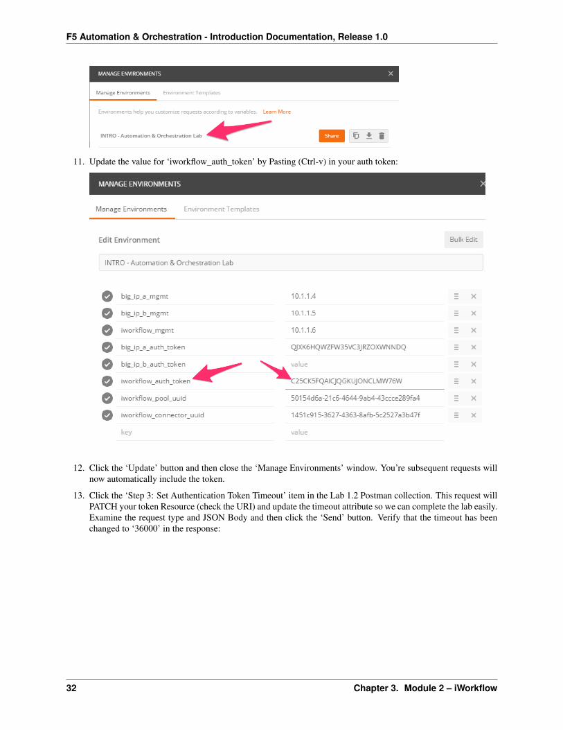
11. Update the value for ‘iworkflow_auth_token’ by Pasting (Ctrl-v) in your auth token:
12. Click the ‘Update’ button and then close the ‘Manage Environments’ window. You’re subsequent requests willnow automatically include the token.
13. Click the ‘Step 3: Set Authentication Token Timeout’ item in the Lab 1.2 Postman collection. This request willPATCH your token Resource (check the URI) and update the timeout attribute so we can complete the lab easily.Examine the request type and JSON Body and then click the ‘Send’ button. Verify that the timeout has beenchanged to ‘36000’ in the response:
32 Chapter 3. Module 2 – iWorkflow

F5 Automation & Orchestration - Introduction Documentation, Release 1.0
3.2 Lab 2.2 – Discover BIG-IP Devices
In order for iWorkflow to interact with a BIG-IP device it must be discovered by iWorkflow. The device discoveryprocess leverages the existing CMI Device Trust infrastructure on BIG-IP. Currently there is a limitation that a singleBIG-IP device can only be ‘discovered’ by ONE of iWorkflow or BIG-IQ CM at a time. In this lab will we discoverthe existing BIG-IP devices from your lab environment.
3.2.1 Task 1 – Discover BIG-IP Devices
Perform the following steps to complete this task:
1. Expand the “Lab 2.2: Discover & License BIG-IP Devices” folder in the Postman collection
2. Open a Google Chrome window/tab to your iWorkflow device (https://10.1.1.6) and login with default creden-tials (admin/admin). You can use this window to monitor actions while they are being performed in Postman.Find the ‘Devices’ pane and make if viewable if it isn’t already.
3. Click the “Step 1: Discover BIGIP-A Device” item in the Post-man collection. This will request will perform a POST to the/mgmt/shared/resolver/device-groups/cm-cloud-managed-devices/devices workerto perform the device discovery process. Examine the JSON body so you understand what data is sent toperform the discovery process:
3.2. Lab 2.2 – Discover BIG-IP Devices 33

F5 Automation & Orchestration - Introduction Documentation, Release 1.0
4. Click the ‘Send’ button. Examine the response and monitor the iWorkflow Chrome window you opened previ-ously.
5. Copy the ‘uuid’ attribute for BIGIP-A and populate the ‘iworkflow_big_ip_a_uuid’ Postman environment vari-able with the value:
34 Chapter 3. Module 2 – iWorkflow

F5 Automation & Orchestration - Introduction Documentation, Release 1.0
6. Repeat steps 1-4 with the “Step 2: Discover BIGIP-B Device” item in the collection.
7. Click the “Step 3: Get Discovered Devices” item in the collection. We will GET the devices collection andverify that both BIG-IP devices show a ‘state’ of ‘ACTIVE’:
3.2. Lab 2.2 – Discover BIG-IP Devices 35

F5 Automation & Orchestration - Introduction Documentation, Release 1.0
3.3 Lab 2.3 – Create Local Connector
Cloud Connectors in iWorkflow serve as the L1-3 Network and Device Onboarding automation component in theautomation toolchain. iWorkflow supports Cloud Connectors for various vendor integrations (F5 vCMP, F5 BIG-IP,Cisco APIC, vmWare NSX, etc.) In this lab we will create a ‘BIG-IP Connector’ for the BIG-IP devices in the UDFdeployment. This connector will then allow you to drive a fully automated deployment from the iWorkflow ServiceCatalog.
3.3.1 Task 1 – Create a Local Connector
In this task we will create a Local Connector that is linked to our BIG-IP devices. The Local Cloud Connector is DSCaware and will automatically detect that the BIG-IP devices are clustered and configure itself accordingly.
Perform the following steps to complete this task:
1. Expand the “Lab 2.3 – Create Local Connector” folder in the Postman collection.
2. Click the “Step 1: Create a Local Connector” item in the collection. We will create a new connector by per-forming a POST to the local connector collection. If you examine the JSON body you can see we are providinga reference to the URL for the BIG-IP-A device (using the UUID environment variable we populated earlier):
3. Click the ‘Send’ button to create the connector.
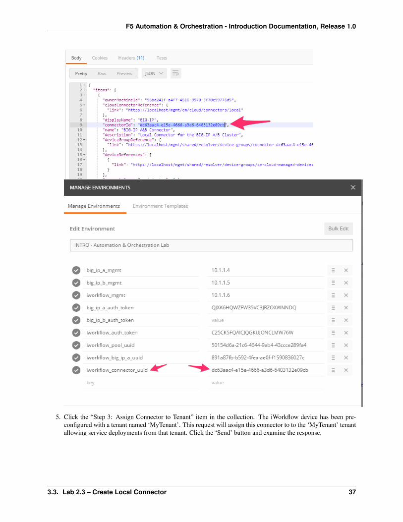
4. Click the “Step 2: Get Local Connectors” item in the collection and click ‘Send’. Examine the output to seehow the connector was configured. Take note of the reference to the ‘device-group’. This is how the connectordetermines the HA state of the underlying BIG-IP devices. Find the ‘connectorId’ of the connector and updateyour Postman environment to include the ‘connectorId’ as the value of the ‘iworkflow_connector_uuid’ variable:
36 Chapter 3. Module 2 – iWorkflow
F5 Automation & Orchestration - Introduction Documentation, Release 1.0
5. Click the “Step 3: Assign Connector to Tenant” item in the collection. The iWorkflow device has been pre-configured with a tenant named ‘MyTenant’. This request will assign this connector to to the ‘MyTenant’ tenantallowing service deployments from that tenant. Click the ‘Send’ button and examine the response.
3.3. Lab 2.3 – Create Local Connector 37

F5 Automation & Orchestration - Introduction Documentation, Release 1.0
3.4 Lab 2.4 – Create an L4–7 Service Template & Deployment
To drive iApp automation-based L4-7 deployments, iWorkflow includes the capability to create a Tenant ServiceCatalog via L4 – L7 Service Templates. This model of deployment enables Declarative automation of F5 L4-7 servicesprovided the underlying iApp templates are designed with a declarative presentation layer in mind. To demonstratethis capability we will create a simple Service Catalog Template and deploy and application from a tenant on ourBIG-IP devices.
3.4.1 Task 1 – Create L4–7 Service Template
An L4-7 Service Deployment on iWorkflow is driven by the creation of an L4 – L7 Service Template. These templatesallow a provider (administrator) to specify the values of specific fields from an origin iApp presentation layer. Addi-tionally, the provider also defines the tenant interface to the service by marking which fields are ‘Tenant Editable’and therefore visible during service deployment from the tenant. You can think of a Service Catalog Template and afilter that allows the vast majority of fields to be filled in or defaulted while only exposing the minimal set of fieldsrequired to deploy a service.
In this task we will create a Service Catalog Template that utilizes the f5.http iApp.
Perform the following steps to complete this task:
1. Expand the “Lab 2.4 – iWorkflow Service Catalog & Service Deployment” folder in the Postman collection
2. Click the “Step 1: Create PROVIDER Service Catalog Template” item in the collection. This request is pre-builtand will create a new template using the f5.http iApp. Click the ‘Send’ button to create the template.
3. Open a Chrome tab to iWorkflow (https://10.1.1.6) and login with admin/admin credentials. Expand the ‘Cata-log’ pane and double-click the “Lab2.4_HTTP” template. Notice the cloud connector was associated as part ofthe REST request, various defaults have been populated (e.g. port ‘80’ for the pool__port variable) and somefields have been marked as ‘Tenant Editable’:
38 Chapter 3. Module 2 – iWorkflow

F5 Automation & Orchestration - Introduction Documentation, Release 1.0
4. Go back to the Postman window and select the “Step 2: Get TENANT Service Catalog Template” item in thecollection. Click the ‘Send’ button and examine the response. Notice that the TENANT definition of the serviceonly shows fields that were marked ‘Tenant Editable’
3.4.2 Task 2 – Tenant L4-7 Service Deployment
In this task we will perform CRUD operations based on a deployment of the Service Catalog Template created in theprevious task.
Perform the following steps to complete this task:
1. Open a new Chrome tab to iWorkflow (https://10.1.1.6) and login with the credentials Username: tenant, Pass-word: tenant. Expand the ‘Services’ pane.
2. Click the “Step 3: Create TENANT Service Deployment” item in the collection. Examine the URL and JSONbody. We will be creating a new Tenant Service Deployment under ‘MyTenant’ with the properties marked as‘Tenant Editable’ provided:
3.4. Lab 2.4 – Create an L4–7 Service Template & Deployment 39

F5 Automation & Orchestration - Introduction Documentation, Release 1.0
3. Click the ‘Send’ button to create the Service Deployment. Examine the response. The iWorkflow GUI in yourChrome tab will also reflect a new item in the Services pane:
40 Chapter 3. Module 2 – iWorkflow
F5 Automation & Orchestration - Introduction Documentation, Release 1.0
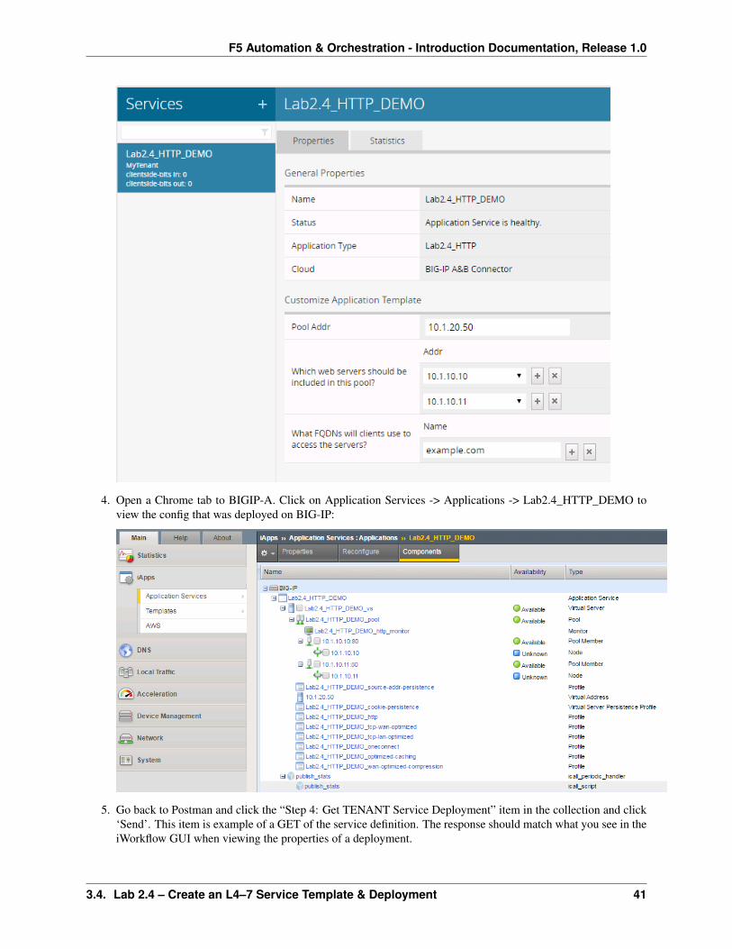
4. Open a Chrome tab to BIGIP-A. Click on Application Services -> Applications -> Lab2.4_HTTP_DEMO toview the config that was deployed on BIG-IP:
5. Go back to Postman and click the “Step 4: Get TENANT Service Deployment” item in the collection and click‘Send’. This item is example of a GET of the service definition. The response should match what you see in theiWorkflow GUI when viewing the properties of a deployment.
3.4. Lab 2.4 – Create an L4–7 Service Template & Deployment 41

F5 Automation & Orchestration - Introduction Documentation, Release 1.0
6. Click the “Step 5: Modify TENANT Service Deployment” item in the collection. This request is an example ofan Update operation. Notice that we are sending a PUT request to the URL representing the service deployment.Examine the JSON body and modify the ‘pool__members’ table to add an additional pool member with an IPof 10.1.10.12. Click the ‘Send’ button to re-deploy the service:
7. Verify that the pool member was added on BIG-IP:
42 Chapter 3. Module 2 – iWorkflow

F5 Automation & Orchestration - Introduction Documentation, Release 1.0
8. Go back to Postman and click the “Step 6: Delete TENANT Service Deployment” item. This item will send aDELETE request to the URL for the service deployment. Click ‘Send’ and verify that the deployment has beenremoved in the iWorkflow and BIG-IP GUIs.
3.5 Lab 2.5 – iWorkflow REST Proxy
In order to enable Imperative automation use cases, iWorkflow includes a REST proxy that allows pass-through ofREST requests to devices managed by iWorkflow. The REST proxy feature allows customers to simplify automationby:
• Providing a centralized API endpoint for BIG-IP infrastructure
– No need to communicate with individual BIG-IP devices, only with iWorkflow
• Simplified authentication
– Strong authentication can be implemented at iWorkflow rather than on each BIG-IP
• Simplified RBAC
– RBAC can be implemented at iWorkflow for all devices rather on individual devices in the environment
The rest proxy works by passing data sent to a specific URL through to the BIG-IP device. The root URL for aparticular devices REST proxy is:
/mgmt/shared/resolver/device-groups/cm-cloud-managed-devices/devices/<device\_uuid>/rest-proxy/
Any URL segments included after .../rest-proxy/ are forwarded unaltered to the BIG-IP device. Query param-eters (e.g. ?expandSubcollections=true) are also passed unaltered along with the request type and requestbody.
3.5. Lab 2.5 – iWorkflow REST Proxy 43

F5 Automation & Orchestration - Introduction Documentation, Release 1.0
3.5.1 Task 1 – Perform REST operations via the REST Proxy
In this task we will perform a sample CRUD operation utilizing the REST Proxy. The intent of this task is to show thebasic mechanism use to perform these tasks. Simply changing the URL to include the iWorkflow REST Proxy root forthat device could easily change all the Imperative operations we have completed in this lab to use the REST Proxy.
Perform the following steps to complete this task:
1. Expand the “Lab 2.5 – iWorkflow REST Proxy” folder in the Postman collection.
2. Click the “Step 1: Create pool on BIGIP-A”. Examine the request type, URL and JSON body. Essentially weare performing a POST to the ‘/mgmt/tm/ltm/pool’ collection on BIGIP-A. The last part of the URL includesthis URI path (the part after ‘. . . ./rest-proxy/’). The JSON body and all other parameters are passed unaltered.Also, notice that we are still using our iWorkflow Token to authenticate, not the BIG-IP one.
3. Click the “Send” button and examine the response.
4. Repeat steps 1-3 for the remaining items in the “Lab 2.5 – iWorkflow REST Proxy” collection. Examine eachrequest carefully so you understand what is happening.
44 Chapter 3. Module 2 – iWorkflow
CHAPTER 4
Module 3 - Python SDK
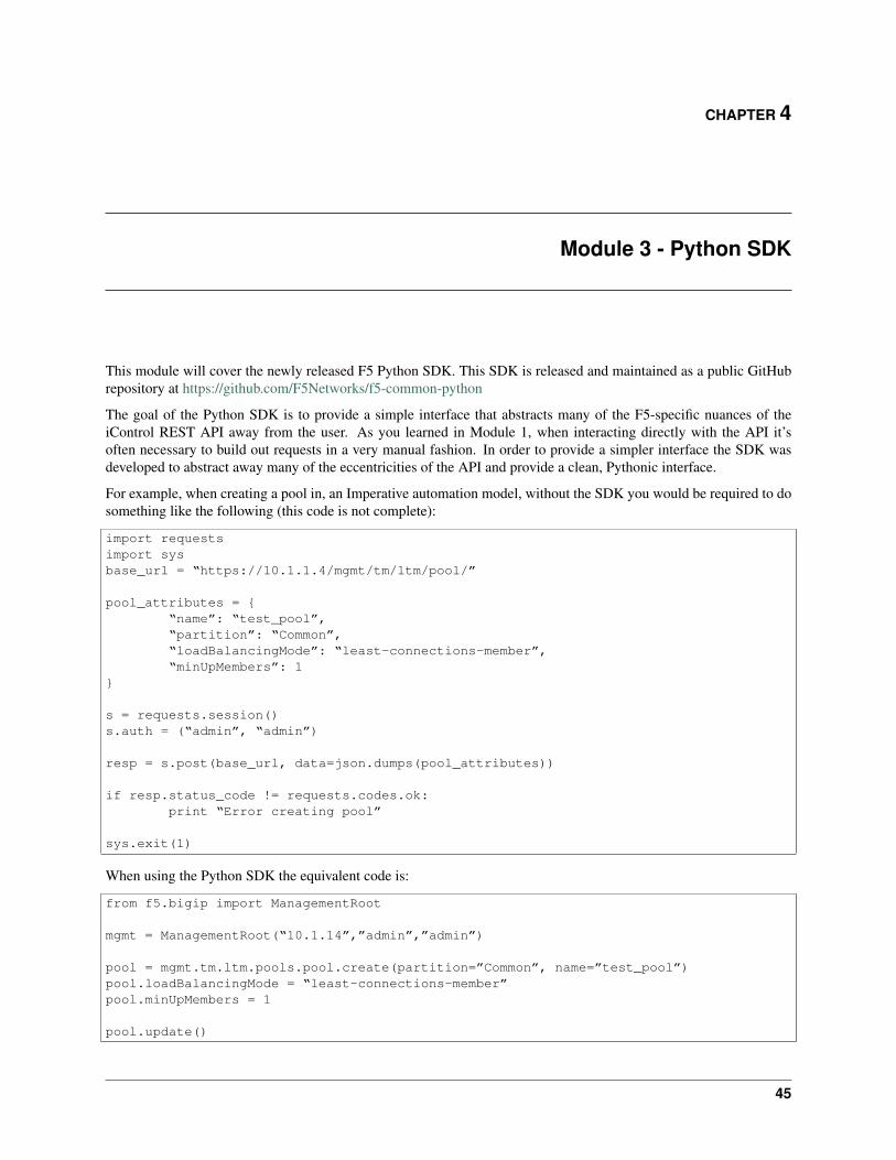
This module will cover the newly released F5 Python SDK. This SDK is released and maintained as a public GitHubrepository at https://github.com/F5Networks/f5-common-python
The goal of the Python SDK is to provide a simple interface that abstracts many of the F5-specific nuances of theiControl REST API away from the user. As you learned in Module 1, when interacting directly with the API it’soften necessary to build out requests in a very manual fashion. In order to provide a simpler interface the SDK wasdeveloped to abstract away many of the eccentricities of the API and provide a clean, Pythonic interface.
For example, when creating a pool in, an Imperative automation model, without the SDK you would be required to dosomething like the following (this code is not complete):
import requestsimport sysbase_url = “https://10.1.1.4/mgmt/tm/ltm/pool/”
pool_attributes = {“name”: “test_pool”,“partition”: “Common”,“loadBalancingMode”: “least-connections-member”,“minUpMembers”: 1
}
s = requests.session()s.auth = (“admin”, “admin”)
resp = s.post(base_url, data=json.dumps(pool_attributes))
if resp.status_code != requests.codes.ok:print “Error creating pool”
sys.exit(1)
When using the Python SDK the equivalent code is:
from f5.bigip import ManagementRoot
mgmt = ManagementRoot(“10.1.14”,”admin”,”admin”)
pool = mgmt.tm.ltm.pools.pool.create(partition=”Common”, name=”test_pool”)pool.loadBalancingMode = “least-connections-member”pool.minUpMembers = 1
pool.update()
45

F5 Automation & Orchestration - Introduction Documentation, Release 1.0
As you can see the code utilizing the SDK is much more condensed and far easier to read. This is a result of theSDK exposing abstracted methods to build the URL. Additionally the SDK creates standard CURDLE (create, update,refresh, delete, load, exists) methods that behave correctly depending on REST object type (Organizing Collection,Collection, Resource, etc.) you are interacting with (e.g., you cannot DELETE an Organizing Collection, therefore adelete() method is not available).
Full documentation for the API exists at here
For the purpose of this lab your Windows Jumphost has everything pre-installed, however, since the SDK is a standardpython package the process is trivial on any system (Windows, Linux, Mac, etc.) that has Python installed.
It’s important to keep in mind while going through this module that we are only demonstrating what is possible withthe SDK from a high level in order to drive a conversation with your customer. For example the same scripts used inthis module are designed to run from the command line with arguments, however, they could easily be modified to useJSON files as the input mechanism.
4.1 Lab 3.1 – create_pool.py
In this lab we will review, line-by-line an example script that has been created to allow creation of a BIG-IP Pool withPool Members directly from the command line.
4.1.1 Task 1 – Review create_pool.py
1. Open Notepad++ using the located in the Windows Taskbar.
2. Double click the file create_pool.py in the menu on the left side of the Notepad++ screen
3. We will now review the code line-by-line:
from f5.bigip import ManagementRootimport pprintimport argparsepp = pprint.PrettyPrinter(indent=3)
These lines import in various Python libraries. The first line imports the F5 Python SDK. The pprint and argparselibraries are standard Python libraries that aid in print data to the console and parsing command line arguments.
parser = argparse.ArgumentParser(description='Script to create a pool on a BIG-IP device')parser.add_argument("host", help="The IP/Hostname of the BIG-IP device")parser.add_argument("pool_name", help="The name of the pool")parser.add_argument("pool_members", help="A comma seperated string in the format <IP>:<port>[,<IP>:<port>]")parser.add_argument("-P", "--partition", help="The partition name", default="Common")parser.add_argument("-u", "--username", help="The BIG-IP username", default="admin")parser.add_argument("-p", "--password", help="The BIG-IP password", default="admin")args = parser.parse_args()
These lines setup the command line arguments for the script and store those arguments in a python dictionary names‘args’. The argparse library automatically generates help text, checks for required arguments, sets defaults, etc.
mgmt = ManagementRoot(args.host, args.username, args.password)
This line creates a new Python object that refers to the BIG-IP device. We are calling the ManagementRoot methodwith 3 arguments:
• The value of the host argument
• The value of the username argument
46 Chapter 4. Module 3 - Python SDK

F5 Automation & Orchestration - Introduction Documentation, Release 1.0
• The value of the password argument
This method automatically performs a test to ensure that we are able to reach the device and authenticate successfully.
pool_path = "/%s/%s" % (args.partition, args.pool_name)
This line just stores the human-readable path to the pool name for later use
if mgmt.tm.ltm.pools.pool.exists(partition=args.partition, name=args.pool_name):raise Exception("Pool '%s' already exists" % args.pool_name)
This if statement checks to see if a pool with the same name already exists on the specified partition on the device. Thereturn value of the exists() method is a Boolean value of True or False. In this case we want the Exception to executeif a pool DOES exist and stop execution of the script.
pool = mgmt.tm.ltm.pools.pool.create(partition=args.partition, name=args.pool_name)print "Created pool %s" % pool_path
The first line in this block actually creates the new pool. The partition and name of the pool are specified as argumentsto the create() method and the ‘pool’ variable represents an object that holds the created pool’s properties. The secondline simply prints a message that the pool has been created.
member_list = args.pool_members.split(',')
This line uses a built-in python method called split() to separate the value of the command line argument into discretestrings using a ‘,’ as a separator. The return type of the split() is a python list (lists = arrays)
for member in member_list:pool_member = pool.members_s.members.create(partition=args.partition, name=member)print " Added member %s" % member
This for loop iterates over the elements in the list generated above and creates a new member in the pool.
4.1.2 Task 2 – Run create_pool.py
1. Open Console2 using the icon on the Windows Taskbar
2. The console window automatically opens in the Desktop\Module 3 – Python SDK directory
3. Type set PYTHONWARNINGS=ignore to disable the printing of SSL/TLS warnings about self-signed cer-tificates.
4. Type python create_pool.py and examine the help output:
5. Type python create_pool.py 10.1.1.4 test_pool 10.1.10.10:80,10.1.10.11:80 tocreate a new pool:
6. Using Chrome open a tab to BIGIP-A (https://10.1.1.4). Examine the pool that was created.
4.1. Lab 3.1 – create_pool.py 47

F5 Automation & Orchestration - Introduction Documentation, Release 1.0
4.2 Lab 3.2 – read_pool.py
In this lab we will review, line-by-line an example script that has been created to view the attributes of a BIG-IP Pooldirectly from the command line.
4.2.1 Task 1 – Review read_pool.py
1. Open read_pool.py in Notepad++
2. We will review the code. For brevity we have removed lines that are common with previous examples:
if not mgmt.tm.ltm.pools.pool.exists(partition=args.partition, name=args.pool_name):raise Exception("Pool '%s' does not exist" % args.pool_name)
This if statement checks to see if a pool with the same name exists in the specified partition on the device. The keydifference between this and the example in the previous lab is the inclusion of the ‘not’ keyword. This inverses thelogic of the statement so that the Exception is raised when the pool DOES NOT exist
pool = mgmt.tm.ltm.pools.pool.load(partition=args.partition, name=args.pool_name)
This line loads the configuration of the pool into a variable
print "Pool %s:" % pool_pathpp.pprint(pool.raw)
These lines print the human-readable pool path and then uses the PrettyPrint library to dump all the attributes associatedwith the pool
4.2.2 Task 2 – Run read_pool.py
1. In the command prompt type python read_pool.py 10.1.1.4 test_pool and examine the output:
48 Chapter 4. Module 3 - Python SDK

F5 Automation & Orchestration - Introduction Documentation, Release 1.0
2. Notice the various attributes that are associated with the pool. Take note of the value of theloadBalancingMode attribute for the next lab
4.3 Lab 3.3 – update_pool.py
In this lab we will review, line-by-line an example script that has been created to allow updating any attribute of a poolusing the command-line. This script is a good example of creating generic tools that enable many use cases. Ratherthan creating a script that just updates a specific attribute we created one that updates ANY pool attribute, greatlyexpanding it’s potential use cases.
4.3.1 Task 1 – Review update_pool.py
1. Open update_pool.py in Notepad++
2. We will review the code. For brevity we have removed lines that are common with previous examples:
pool = mgmt.tm.ltm.pools.pool.load(partition=args.partition, name=args.pool_name)
pp.pprint("Current: %s=%s" % (args.attribute, getattr(pool, args.attribute)))
These lines load the pool from the device and print the current value of the attribute specified on the the command line.The second line is a little bit tricky because the SDK dynamically populates the objects attributes based on the typeof object (pool, virtual server, etc.). Normally we could just use something like ‘pool.loadBalancingMode’ to get thecurrent lb-method for the pool, however, since this script implements a way to change ANY attribute in the object we
4.3. Lab 3.3 – update_pool.py 49

F5 Automation & Orchestration - Introduction Documentation, Release 1.0
have to dynamically substitute the attribute name at run-time. To do this we use the getattr() python built-in functionto resolve the mapping at runtime and return the value of the attribute specified on the command line.
kwargs = {args.attribute: args.value}
This line creates a new python dictionary with one entry specifying a key-value pair using the command line arguments.For example if you were updated the loadBalancingMode attribute to ‘least-connections-member’ the dictionary wouldlook like {“loadBalancingMode”:”least-connections-member”}
pool.update(**kwargs)
The first line updates the pool we loaded previously with the new value for the attribute. The **kwargs argument tothe update() method triggers a special mechanism in python called ‘keyword unpacking’ which allows us to pass theattribute to be updated to the update() method.
pool.refresh()pp.pprint("New: %s=%s" % (args.attribute, getattr(pool, args.attribute)))
The first line refreshes the data in the object from the BIG-IP device. The second line prints this refreshed informationto the console so the user can verify the update completed successfully.
4.3.2 Task 2 – Run update_pool.py
1. In the command prompt type python update_pool.py 10.1.1.4 test_poolloadBalancingMode least-connections-member and examine the output:
2. You can manually verify the load balancing method was changed via TMUI or by re-running read_pool.py(it’s not required since the line that prints the new value forces a refresh() )
3. Experiment with changing other pool attributes
4.4 Lab 3.4 – update_pool_member_state.py
One of the most common tasks asked for by customers is the ability to set a pool member’s state via a script. We haveincluded an example of such a script in the lab that can be used to show customers how easy it’s to automate specificoperational tasks.
4.4.1 Task 1 – Run update_pool_member_state.py
1. In the command prompt type python update_pool_member_state.py 10.1.1.4 test_pool10.1.10.10:80 disabled and examine the output.
2. Verify the pool member was disabled via TMUI
3. Re-run the script with as python update_pool_member_state.py --help to see additional options.
4. Re-enable the pool member using the script
50 Chapter 4. Module 3 - Python SDK

F5 Automation & Orchestration - Introduction Documentation, Release 1.0
4.5 Lab 3.5 – delete_pool.py
In this lab we will review, line-by-line an example script that has been created to allow deletion of a pool using thecommand-line.
4.5.1 Task 1 – Review delete_pool.py
1. Open delete_pool.py in Notepad++
2. We will review the code. For brevity we have removed lines that are common with previous examples:
pool = mgmt.tm.ltm.pools.pool.load(partition=args.partition, name=args.pool\_name)pool.delete()
print "Deleted pool %s" % pool\_path
These lines should be fairly self-explanatory at this point. First we load the pool and the we delete() it and print thatwe have done so.
4.5.2 Task 2 – Run delete_pool.py
1. In the command prompt type python delete_pool.py 10.1.1.4 test_pool and examine the out-put:
2. If desired verify the pool was deleted using TMUI or the read_pool.py script (it should return an error)
4.6 Lab 3.6 – Create a Python Script
In this lab we will use the ‘Generate Code’ feature of Postman to create a python script from a collection of requests.
4.6.1 Task 1 – Create a simple script
Perform the following steps to complete this task:
1. Expand the ‘Lab 3.6 – Create a Python Script’ folder in the Postman collection
2. Click the ‘Step 1 – Create a HTTP Monitor’ item in the collection
3. Click the ‘Generate Code’ link in the Postman window:
4.5. Lab 3.5 – delete_pool.py 51

F5 Automation & Orchestration - Introduction Documentation, Release 1.0
4. Select Python -> Requests from the menu on the top right of the window:
5. Examine the Python code that was generated. Click the ‘Copy to Clipboard’ button
6. Open a new text file and paste the generated code. We need to modify the line that sends the request to DISABLESSL certificate verification. Find the following line:
response = requests.request("POST", url, data=payload, headers=headers)
And add a verify=False option to it:
response = requests.request("POST", url, data=payload, headers=headers, verify=False)
Save the file on your Desktop as lab3_6.py
52 Chapter 4. Module 3 - Python SDK

F5 Automation & Orchestration - Introduction Documentation, Release 1.0
7. Open a command prompt and run the script by typing python lab3_6.py:
8. Verify the monitor was created on BIG-IP
9. Delete the monitor to prepare for the next task
4.6.2 Task 2 – Chain together multiple requests
In this task we will repeat the process from Task 1 to chain together multiple requests.
Perform the following steps:
1. Repeat the procedure from Task 1 with each of the items in the ‘Lab 3.6’ postman collection. Append eachsnippet of code to your existing script until you have all 5 requests in the script. You will need to remove theduplicate ‘import requests’ lines and update each request with the ‘verify=False’ option.
2. Save the file
3. Run the script and verify the config was created.
4.7 Lab 3.7 – EXTRA CREDIT – Modify create_pool.py
This is an open-ended exercise. Copy create_pool.py to create_vs.py and modify it to create a VirtualServer. You could also cheat and look at you_cheated.py!
4.8 Lab 3.8 – EXTRA CREDIT – Review super_pool.py
This is an open-ended exercise. Review and run the super_pool.py script. This script allows bulk creation/deletionof pools using CSV files.
4.7. Lab 3.7 – EXTRA CREDIT – Modify create_pool.py 53