f70 pr series - tri-state meter files/flow safe/series...f70 pr series pilot-operated pressure...
TRANSCRIPT
F70 PR SeriesPilot-Operated Pressure Relief Valves
CATALOG # F70PR0499
The policy of FLOW SAFE and its authorizedassemblers is a commitment to value through:
● Environmentally Compatible Products
● Cost Effficient Design, with minimal parts
● Quality Products, Readily Available
● Flexibility, to meet Unique Customer Needs
● "No Hassle" Service
INTRODUCTIONToday's Natural Gas and Process Industriesrequire leaktight valves to reduce emissions, saveproduct, and minimize horsepower requirements.
The F70PR Series "High Performance" PilotOperated pressure relief valves accomplishbubble-tight sealing with accurate and consistentoperational characteristics.
F70PR design features include:
● MODULATING VALVE ACTION
-"LESS PRODUCT LOSS"
● ELASTOMERIC SEAT & SEALS
● REPEATABLE BUBBLE-TIGHT SEATING
● RUGGED, SIMPLE, & EFFICIENT DESIGN
● SUPERIOR FLOW CAPACITIES
● 10"WC to 285 psig PRESSURE RANGE
● -65 to +400 0 F SERVICE TEMPERATURE RANGE
● EASY & ECONOMICAL INSTALLATION
● INLINE MAINTENANCE CAPABILITY
● PILOT EXHAUST TO MAIN VALVE - STANDARD
● CAPACITIES INDEPENDENTLY VERIFIED
● DISCHARGE DRAIN PLUG STANDARD
● LIFT BRACKETS-2x3 AND LARGER - STANDARD
● LOW UPSET RATIO (Piston Area/Seat Area)
● DOT COMPLIANCY
CONTENTS
SECTION PAGES
CONTENTS & INTRODUCTION ......... 2
OPERATION ..................................... 3
APPLICATIONS● Natural Gas ....................................... 4
● Process Industries .............................. 5
● Positive Displacement
Blower Packages ............................ 5
ENGINEERING DATA● Construction
-Main Valve Assemblies
High Pressure .............................. 6-7
Low Pressure............................... 8-9
-Pilot Valve Assemblies .................. 10
● Accessories ...................................... 11
● Sizing Formulas ............................... 12
● Flow Capacities ............................... 13
● Specifications ................................... 14
● Dimensions & Weights. .................... 14
● How to Order &
Part Numbers ............................... 15
● Other FLOW SAFE
Products ...................................... 16
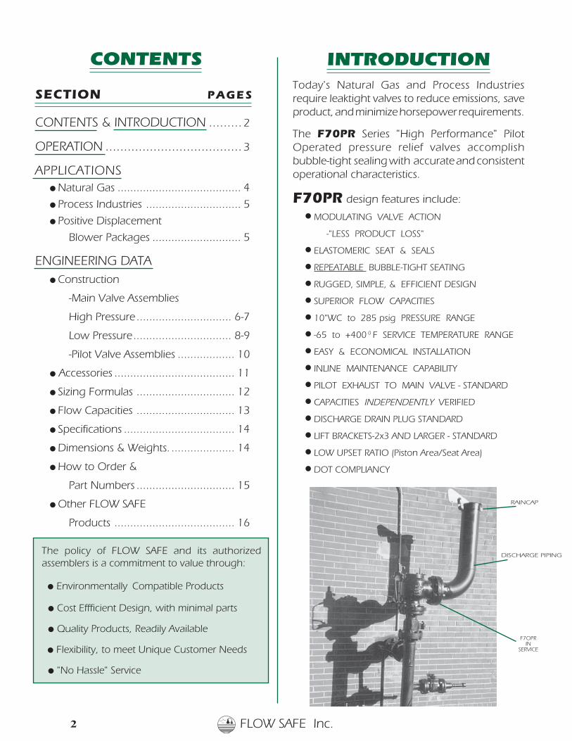
RAINCAP
DISCHARGE PIPING
F7OPRIN
SERVICE
2 FLOW SAFE Inc.

FLOW SAFE Inc. 3
FF
F100 PILOT VALVE
OUTLET
INLETDRAIN PLUG
DOME CAVITY
LIFT BRACKET
PRESSURE PICKUP
PISTON
LINER
TUBE
BODY
ASSEMBLY
System pressure is routed from the inlet below the valve, through a modulating pilot valve to the dome cavityof the valve. At the designated set pressure, the pilot valve reduces the dome pressure, proportional todemand at the set pressure, and allows the piston to go into lift. Once system pressure is relieved, the pilotvalve closes, allowing the dome to repressurize and the main valve piston to close.
When closed, dome pressure acting on a differential area between the top and bottom of the pistonassembly, creates a downward force on the seat providing bubble-tight shutoff.
The F70PR utilizes an elastomeric seat on the piston to achieve bubble-tight seating. A dynamic piston sealprevents any leakage from the dome to the discharge. Guide rings on the piston prevent any metal-to-metalcontact, and help to provide smooth, consistent, and repeatable operation.
DOME PRESSURE
OPERATION
CLOSED OPENUNPRESSURIZED
INLET PRESSURE
F100 LOW PRESSURE ASSEMBLY(10" WC - 5 psig)
F100 HIGH PRESSURE ASSEMBLY(5 - 285 psig)
OUTLET PRESSURE
F70PR SERIES
PRESSURE INLET
DOME FEED
PRESSURE DISCHARGE
MAIN VALVE CAP
F
F
PRESSURE INLET
DOME
DISCHARGEPRESSURE
MAIN VALVE CAP
(AT SET POINT)
FEED
FLOW SAFE Inc.4
APPLICATIONS F7OPR SERIES
Natural GasThe F70PR Pressure Relief Valve provides overpressure safety protection for natural gas distri-bution or transmission applications, with the ability to handle large volumes and provide con-sistent, bubble-tight shutoff before and after a system upset.
The F70PR is designed to be repeatedly cycled at full pressure throughout its acceptable range oftemperatures. It is ideal for systems that require overpressure protection, and utilizes modulating actionto improve process efficiency and reduce product loss. The F70PR's 100 Series pilot valve is bubble-tight to the set point upon opening, and to 95% of the set point upon closure, allowing the user tooperate close to the nameplate set pressure. A maximum of 10% overpressure is required to fully openthe valve.
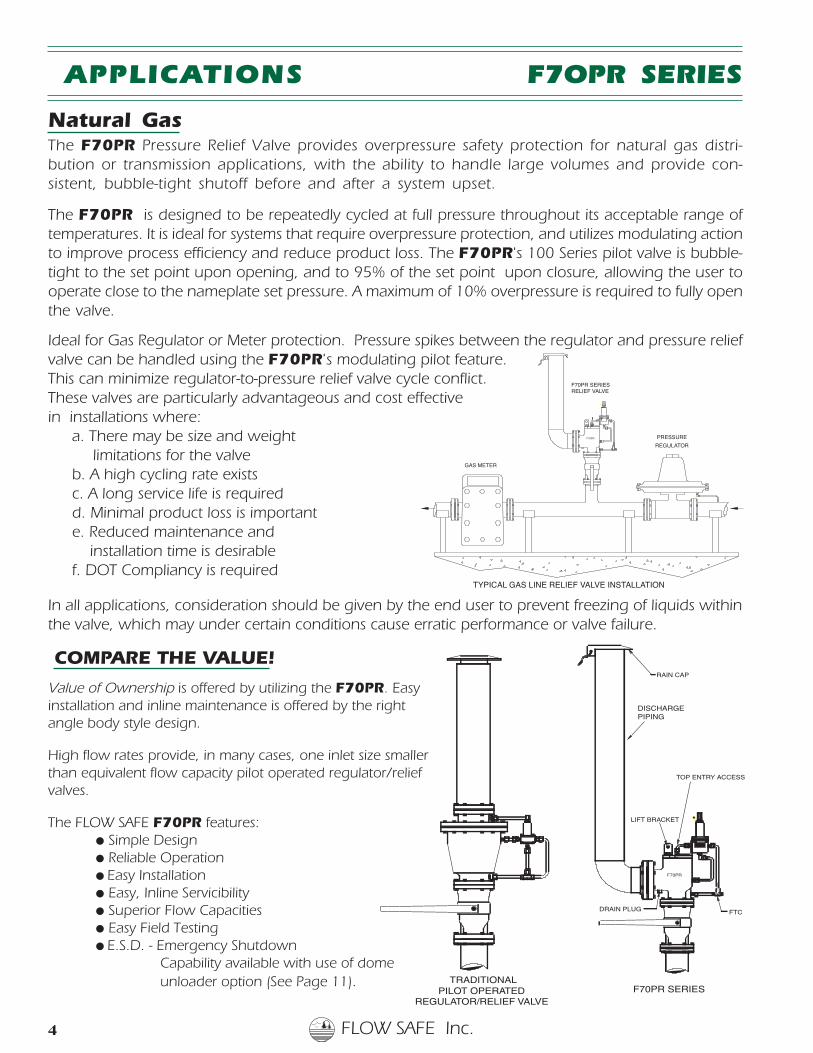
Ideal for Gas Regulator or Meter protection. Pressure spikes between the regulator and pressure reliefvalve can be handled using the F70PR's modulating pilot feature.This can minimize regulator-to-pressure relief valve cycle conflict.These valves are particularly advantageous and cost effectivein installations where:
a. There may be size and weightlimitations for the valve
b. A high cycling rate existsc. A long service life is requiredd. Minimal product loss is importante. Reduced maintenance and
installation time is desirablef. DOT Compliancy is required
In all applications, consideration should be given by the end user to prevent freezing of liquids withinthe valve, which may under certain conditions cause erratic performance or valve failure.
COMPARE THE VALUE!
Value of Ownership is offered by utilizing the F70PR. Easyinstallation and inline maintenance is offered by the rightangle body style design.
High flow rates provide, in many cases, one inlet size smallerthan equivalent flow capacity pilot operated regulator/reliefvalves.
The FLOW SAFE F70PR features:● Simple Design● Reliable Operation● Easy Installation● Easy, Inline Servicibility● Superior Flow Capacities● Easy Field Testing● E.S.D. - Emergency Shutdown
Capability available with use of dome unloader option (See Page 11).
F
F70PR
RELIEF VALVE
REGULATOR
GAS METER
PRESSURE
TYPICAL GAS LINE RELIEF VALVE INSTALLATION
F70PR SERIES
FLOW SAFE Inc. 5
F
F70PR
F70PR SERIES
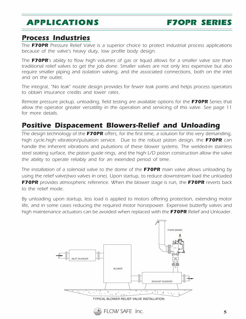
TYPICAL BLOWER RELIEF VALVE INSTALLATION
EXHAUST SILENCER
INLET SILENCER
BLOWER
APPLICATIONS F7OPR SERIES
Process IndustriesThe F70PR Pressure Relief Valve is a superior choice to protect industrial process applicationsbecause of the valve's heavy duty, low profile body design.
The F70PR's ability to flow high volumes of gas or liquid allows for a smaller valve size thantraditional relief valves to get the job done. Smaller valves are not only less expensive but alsorequire smaller piping and isolation valving, and the associated connections, both on the inletand on the outlet.
The integral, "No leak" nozzle design provides for fewer leak points and helps process operatorsto obtain insurance credits and lower rates.
Remote pressure pickup, unloading, field testing are available options for the F70PR Series thatallow the operator greater versatility in the operation and servicing of this valve. See page 11for more details.
Positive Dispacement Blowers-Relief and UnloadingThe design technology of the F70PR offers, for the first time, a solution for this very demanding,high cycle,high vibration/pulsation service. Due to the robust piston design, the F70PR canhandle the inherent vibrations and pulsations of these blower systems. The welded-in stainlesssteel seating surface, the piston guide rings, and the high L/D piston construction allow the valvethe ability to operate reliably and for an extended period of time.
The installation of a solenoid valve to the dome of the F70PR main valve allows unloading byusing the relief valve(two valves in one). Upon startup, to reduce downstream load the unloadedF70PR provides atmospheric reference. When the blower stage is run, the F70PR reverts backto the relief mode.
By unloading upon startup, less load is applied to motors offering protection, extending motorlife, and in some cases reducing the required motor horsepower. Expensive butterfly valves andhigh maintenance actuators can be avoided when replaced with the F70PR Relief and Unloader.
FLOW SAFE Inc.6
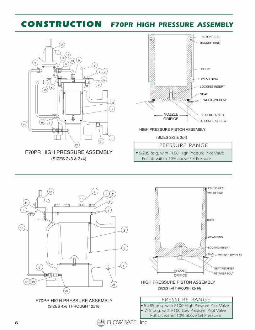
CONSTRUCTION F70PR HIGH PRESSURE ASSEMBLY
SEAT RETAINER
RETAINER BOLT
WELDED OVERLAY
LOCKING INSERT
NOZZLEORIFICE
SEAT
WEAR RING
BODY
WEAR RING
PISTON SEAL
HIGH PRESSURE PISTON ASSEMBLY(SIZES 4x6 THROUGH 12x16)
● 5-285 psig, with F100 High Pressure Pilot Valve Full Lift within 10% above Set Pressure
ORIFICENOZZLE
RETAINER SCREW
WELD OVERLAY
SEAT RETAINER
LOCKING INSERT
WEAR RING
SEAT
BODY
PISTON SEAL
BACKUP RING
HIGH PRESSURE PISTON ASSEMBLY
(SIZES 2x3 & 3x4)
● 5-285 psig, with F100 High Pressure Pilot Valve● 2- 5 psig, with F100 Low Pressure Pilot Valve
Full Lift within 10% above Set Pressure
PRESSURE RANGE
PRESSURE RANGE
F
13
9
11
13
1
2
3
4
5
6 78
9
1918
20
21
F70PR HIGH PRESSURE ASSEMBLY(SIZES 4x6 THROUGH 12x16)
F
12
911
10
13
17
16 9
15
9
14
1
2
3
4
5
6 7
89
2021
F70PR HIGH PRESSURE ASSEMBLY(SIZES 2x3 & 3x4)
FLOW SAFE Inc. 7
9
24
21
11
21
1-1/2 FNPT
21
22
14
13
1
9
20
7
3
5
6
2.75
3.00
4
2 FNPT
F
F70PR
(SIZ
A
23
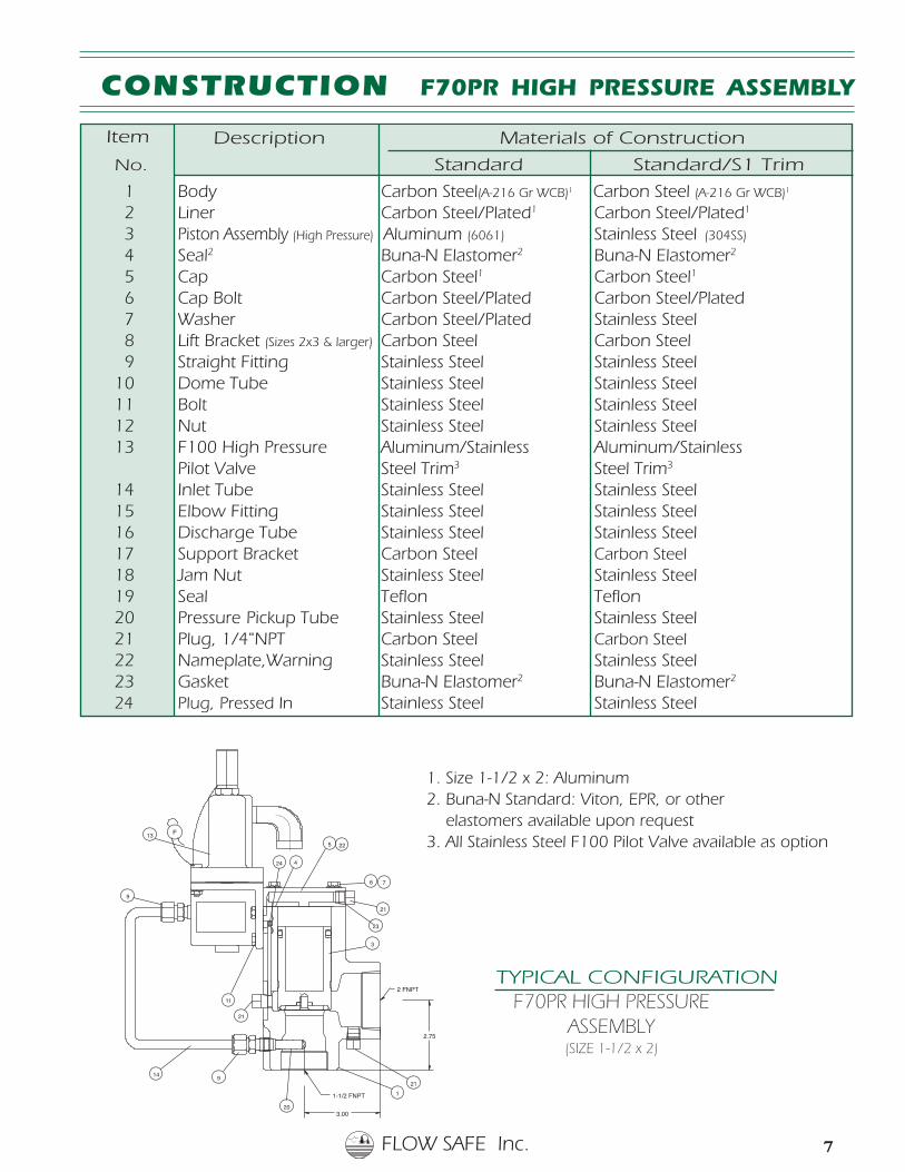
Item Description Materials of Construction
No. Standard Standard/S1 Trim
1 Body Carbon Steel(A-216 Gr WCB)1 Carbon Steel (A-216 Gr WCB)1
2 Liner Carbon Steel/Plated1 Carbon Steel/Plated1
3 Piston Assembly (High Pressure) Aluminum (6061) Stainless Steel (304SS)
4 Seal2 Buna-N Elastomer2 Buna-N Elastomer2
5 Cap Carbon Steel1 Carbon Steel1
6 Cap Bolt Carbon Steel/Plated Carbon Steel/Plated 7 Washer Carbon Steel/Plated Stainless Steel 8 Lift Bracket (Sizes 2x3 & larger) Carbon Steel Carbon Steel 9 Straight Fitting Stainless Steel Stainless Steel10 Dome Tube Stainless Steel Stainless Steel11 Bolt Stainless Steel Stainless Steel12 Nut Stainless Steel Stainless Steel13 F100 High Pressure Aluminum/Stainless Aluminum/Stainless
Pilot Valve Steel Trim3 Steel Trim3
14 Inlet Tube Stainless Steel Stainless Steel15 Elbow Fitting Stainless Steel Stainless Steel16 Discharge Tube Stainless Steel Stainless Steel17 Support Bracket Carbon Steel Carbon Steel18 Jam Nut Stainless Steel Stainless Steel19 Seal Teflon Teflon20 Pressure Pickup Tube Stainless Steel Stainless Steel21 Plug, 1/4"NPT Carbon Steel Carbon Steel22 Nameplate,Warning Stainless Steel Stainless Steel23 Gasket Buna-N Elastomer2 Buna-N Elastomer2
24 Plug, Pressed In Stainless Steel Stainless Steel
CONSTRUCTION F70PR HIGH PRESSURE ASSEMBLY
Item
1. Size 1-1/2 x 2: Aluminum2. Buna-N Standard: Viton, EPR, or other elastomers available upon request3. All Stainless Steel F100 Pilot Valve available as option
TYPICAL CONFIGURATIONF70PR HIGH PRESSURE
ASSEMBLY(SIZE 1-1/2 x 2)
FLOW SAFE Inc.8
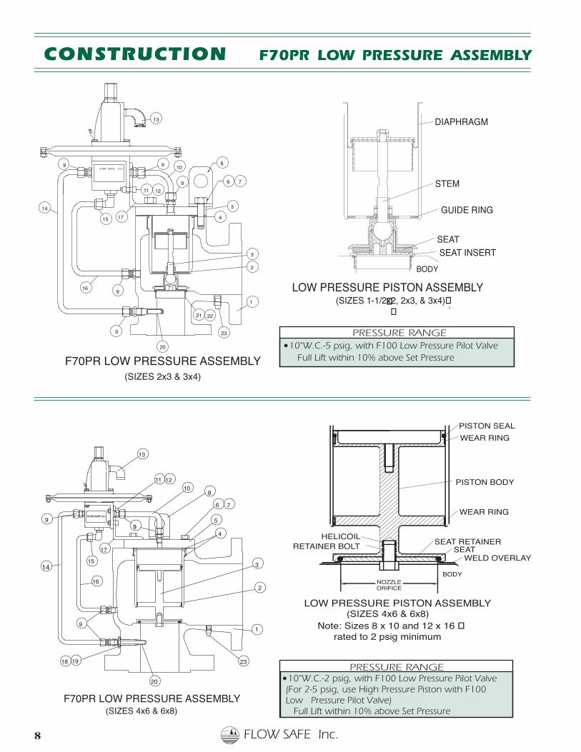
CONSTRUCTION F70PR LOW PRESSURE ASSEMBLY
PRESSURE RANGE ● 10"W.C.-2 psig, with F100 Low Pressure Pilot Valve (For 2-5 psig, use High Pressure Piston with F100 Low Pressure Pilot Valve) Full Lift within 10% above Set Pressure
BODY
SEAT INSERTSEAT
DIAPHRAGM
GUIDE RING
STEM
LOW PRESSURE PISTON ASSEMBLY�
�
(SIZES 1-1/2x2, 2x3, & 3x4)��
20
23
1
3
2
4
5
6 7
810
19
9
18
14
16
15
9
13
11 12
9
17
FLOW SAFE, Inc.
F
F70PR LOW PRESSURE ASSEMBLY(SIZES 4x6 & 6x8)
PRESSURE RANGE● 10"W.C.-5 psig, with F100 Low Pressure Pilot Valve Full Lift within 10% above Set Pressure
(SIZES 4x6 & 6x8)LOW PRESSURE PISTON ASSEMBLY
PISTON BODY
NOZZLEORIFICE
RETAINER BOLTHELICOIL
BODY
WELD OVERLAY
SEAT RETAINERSEAT
WEAR RING
WEAR RING
PISTON SEAL
Note: Sizes 8 x 10 and 12 x 16 �rated to 2 psig minimum
13
9
14
16
9
9
1
3
23
2221
2
15
6
8
20
11
10
12
F
4
5
79
17
9FLOW SAFE, Inc.
F70PR LOW PRESSURE ASSEMBLY(SIZES 2x3 & 3x4)
FLOW SAFE Inc. 9
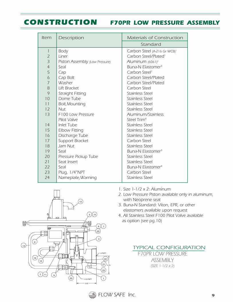
Description Materials of Construction
Standard
1 Body Carbon Steel (A-216 Gr WCB)1
2 Liner Carbon Steel/Plated1
3 Piston Assembly (Low Pressure) Aluminum (6061)2
4 Seal Buna-N Elastomer3
5 Cap Carbon Steel1
6 Cap Bolt Carbon Steel/Plated 7 Washer Carbon Steel/Plated 8 Lift Bracket Carbon Steel 9 Straight Fitting Stainless Steel10 Dome Tube Stainless Steel11 Bolt,Mounting Stainless Steel12 Nut Stainless Steel13 F100 Low Pressure Aluminum/Stainless
Pilot Valve Steel Trim4
14 Inlet Tube Stainless Steel15 Elbow Fitting Stainless Steel16 Discharge Tube Stainless Steel17 Support Bracket Carbon Steel18 Jam Nut Stainless Steel19 Seal Buna-N Elastomer3
20 Pressure Pickup Tube Stainless Steel21 Seat Insert Stainless Steel22 Seal Buna-N Elastomer4
23 Plug, 1/4"NPT Carbon Steel24 Nameplate,Warning Stainless Steel
CONSTRUCTION F70PR LOW PRESSURE ASSEMBLY
Item
1. Size 1-1/2 x 2: Aluminum2. Low Pressure Piston available only in aluminum, with Neoprene seat3. Buna-N Standard: Viton, EPR, or other elastomers available upon request4. All Stainless Steel F100 Pilot Valve available as option (see pg.10)
TYPICAL CONFIGURATIONF70PR LOW PRESSURE
ASSEMBLY(SIZE 1-1/2 x 2)
FLOW SAFE Inc.10
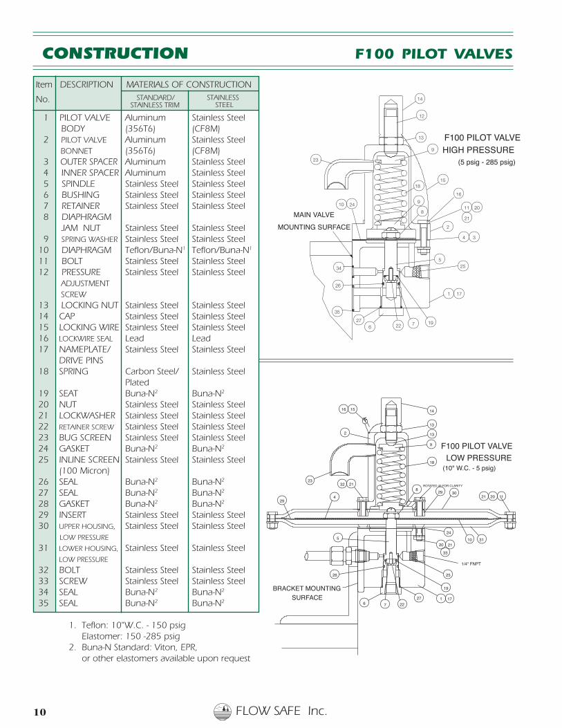
Item DESCRIPTION MATERIALS OF CONSTRUCTION
No.
1 PILOT VALVE Aluminum Stainless Steel BODY (356T6) (CF8M) 2 PILOT VALVE Aluminum Stainless Steel
BONNET (356T6) (CF8M) 3 OUTER SPACER Aluminum Stainless Steel 4 INNER SPACER Aluminum Stainless Steel 5 SPINDLE Stainless Steel Stainless Steel 6 BUSHING Stainless Steel Stainless Steel 7 RETAINER Stainless Steel Stainless Steel 8 DIAPHRAGM JAM NUT Stainless Steel Stainless Steel 9 SPRING WASHER Stainless Steel Stainless Steel 10 DIAPHRAGM Teflon/Buna-N1 Teflon/Buna-N1
11 BOLT Stainless Steel Stainless Steel 12 PRESSURE Stainless Steel Stainless Steel
ADJUSTMENT SCREW 13 LOCKING NUT Stainless Steel Stainless Steel 14 CAP Stainless Steel Stainless Steel 15 LOCKING WIRE Stainless Steel Stainless Steel 16 LOCKWIRE SEAL Lead Lead 17 NAMEPLATE/ Stainless Steel Stainless Steel DRIVE PINS 18 SPRING Carbon Steel/ Stainless Steel
Plated 19 SEAT Buna-N2 Buna-N2
20 NUT Stainless Steel Stainless Steel 21 LOCKWASHER Stainless Steel Stainless Steel 22 RETAINER SCREW Stainless Steel Stainless Steel 23 BUG SCREEN Stainless Steel Stainless Steel 24 GASKET Buna-N2 Buna-N2
25 INLINE SCREEN Stainless Steel Stainless Steel (100 Micron) 26 SEAL Buna-N2 Buna-N2
27 SEAL Buna-N2 Buna-N2
28 GASKET Buna-N2 Buna-N2
29 INSERT Stainless Steel Stainless Steel 30 UPPER HOUSING, Stainless Steel Stainless Steel
LOW PRESSURE
31 LOWER HOUSING, Stainless Steel Stainless SteelLOW PRESSURE
32 BOLT Stainless Steel Stainless Steel 33 SCREW Stainless Steel Stainless Steel 34 SEAL Buna-N2 Buna-N2
35 SEAL Buna-N2 Buna-N2
1. Teflon: 10"W.C. - 150 psig Elastomer: 150 -285 psig2. Buna-N Standard: Viton, EPR, or other elastomers available upon request
27
29
23
F
14
13
15
132
9
8
16
21
21 112030
10
4
20
1
ROTATED 45 FOR CLARITY
29
21
24
33
18
32
31
2526
6 7 22
19BRACKET MOUNTINGSURFACE
1/4" FNPT
5
F100 PILOT VALVE
LOW PRESSURE(10" W.C. - 5 psig)
17
CONSTRUCTION F100 PILOT VALVES
35
34
26
27
10
34
21
24
25
23
9
1
22
2011
2
1815
16
14
13
12
8
76
5
19
MAIN VALVE
MOUNTING SURFACE
F100 PILOT VALVEHIGH PRESSURE
(5 psig - 285 psig)
17
9
STANDARD/STAINLESS TRIM
STAINLESS STEEL

FLOW SAFE Inc. 11
Remote-Unload Blowdown(SC or SO)Allows for main valve lift by bypassing the pilot valve. Ideal as anunloading valve to eliminate/vent system pressure for positivedisplacement blowers, or to act as an Emergency ShutdownDevice(ESD)for the natural gas compressor industry.Accomplished by use of an automatic blowdown valve, pneumatic, hydraulic, or electric valve. Automaticvalves can be provided in AC or DC, Normally Closed or Normally Open(preferred as fail safe)
Backflow Preventer(P) (Part No. 00-4501-03)To prevent backflow into the system, when outlet pressureexceeds the inlet pressure, a backflow preventer can beprovided. The outlet pressure is routed to the main valvedome, to ensure that the piston remains closed.
Closed Dome Tee(D) (Part No. 00-6001)This allows the user to verify the set pressure while in service without valve removal. A tee is provided on themain valve cap to attach a gage or any other instrumentation.
Diverter Assembly(V) (Part No. 52-100X)Two F70PR's can be supplied with a diverter valve to allow switching for maintenance and servicing.
Dual Pilot Valves(Y)Two F100 Pilot Valves can be supplied mounted to the F70 main valve assembly, with a switchover valve inbetween. The Pilot valves can be set at two separate set pressures, allowing the operator the flexibility tochange the set point or perform maintenance on one of the pilot valves.
Field Test Connection(T) (Part No. 00-4450-01)This allows the user to verify the set pressure while in service withoutvalve removal. An external pressure source may be attached to theFTC to direct pressure to the pilot valve, while blockingoff the inlet pressure, thus checking the set pressureand the general operation of the valve.
Inlet Supply Filter (F)(Part No. 12-4302)
This should be used for dirty applications to
clean the supply gas to the pilot valve.
This is supplied with a purge vent.
Remote Pressure Pickup(R)Remote pressure pickup is recommended when inlet pipingpressure losses exceed 3% to the relief valve. This allows aremote, more direct pressure sensing to the pilot valve, plusan excellent source of clean air. INLET
OUTLETFLOW SAFE INC.
N
REMOTE
PICKUP
F70PR
BACKFLOW PREVENTER
F
CHECK VALVE
MAIN VALVE
OUTLET
FILTER
TO PILOT VALVE
1/2"FNPT
FIELD TEST
TO PILOT VALVE
CONNECTION
Manual Blowdown(M) (Part No. 00-4600)Allows for main valve lift by bypassing the pilot valve.Accomplished by a manual blowdown valve.
MANUAL VALVE
F
SOLENOID VALVE
F
OR CONTROL VALVE
ACCESSORIES AND OPTIONS F70PR SERIES
FLOW SAFE Inc.12
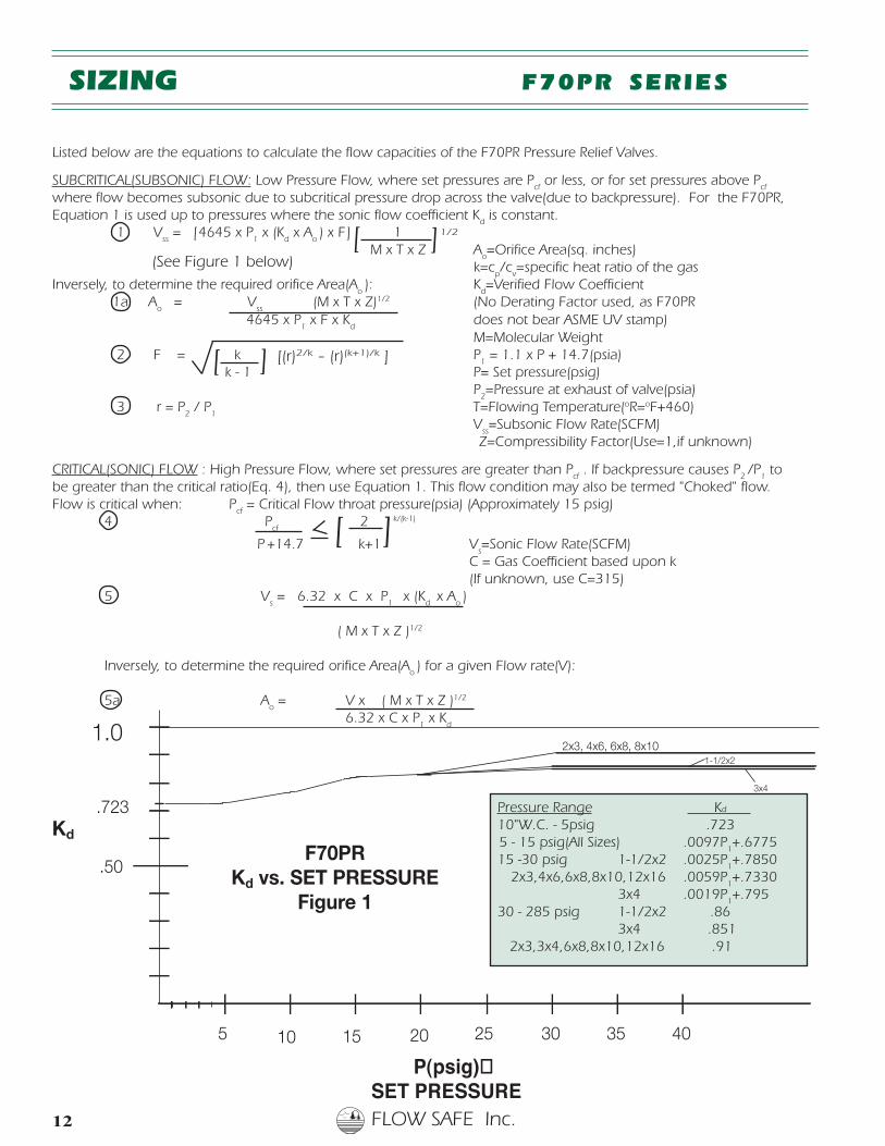
Listed below are the equations to calculate the flow capacities of the F70PR Pressure Relief Valves.
SUBCRITICAL(SUBSONIC) FLOW: Low Pressure Flow, where set pressures are Pcf or less, or for set pressures above P
cf
where flow becomes subsonic due to subcritical pressure drop across the valve(due to backpressure). For the F70PR,Equation 1 is used up to pressures where the sonic flow coefficient K
d is constant.
1 Vss = [4645 x P
1 x (K
d x A
o) x F] 1
M x T x Z Ao=Orifice Area(sq. inches)
k=cp/c
v=specific heat ratio of the gas
Inversely, to determine the required orifice Area(Ao): K
d=Verified Flow Coefficient
1a Ao = V
ss(M x T x Z)1/2 (No Derating Factor used, as F70PR
4645 x P1 x F x K
d does not bear ASME UV stamp) M=Molecular Weight
2 F = k P1 = 1.1 x P + 14.7(psia)
k - 1 P= Set pressure(psig) P
2=Pressure at exhaust of valve(psia)
3 r = P2 / P
1 T=Flowing Temperature(oR=oF+460) V
ss=Subsonic Flow Rate(SCFM)
Z=Compressibility Factor(Use=1,if unknown)
CRITICAL(SONIC) FLOW : High Pressure Flow, where set pressures are greater than Pcf . If backpressure causes P
2/P
1 to
be greater than the critical ratio(Eq. 4), then use Equation 1. This flow condition may also be termed "Choked" flow.Flow is critical when: P
cf = Critical Flow throat pressure(psia) (Approximately 15 psig)
4 Pcf 2 k/(k-1)
P +14.7 k+1 Vs=Sonic Flow Rate(SCFM)
C = Gas Coefficient based upon k(If unknown, use C=315)
5 Vs = 6.32 x C x P
1 x (K
d x A
o)
( M x T x Z )1/2
Inversely, to determine the required orifice Area(Ao) for a given Flow rate(V):
5a Ao
= V x ( M x T x Z )1/2
6.32 x C x P1 x K
d
Kd
F70PRKd vs. SET PRESSURE
Figure 1
P(psig)�SET PRESSURE
SIZING F70PR SERIES
[ ]1/2
[(r)2/k - (r)(k+1)/k ]] [
][
Pressure Range Kd
10"W.C. - 5psig .7235 - 15 psig(All Sizes) .0097P
1+.6775
15 -30 psig 1-1/2x2 .0025P1+.7850
2x3,4x6,6x8,8x10,12x16 .0059P1+.7330
3x4 .0019P1+.795
30 - 285 psig 1-1/2x2 .863x4 .851
2x3,3x4,6x8,8x10,12x16 .91
(See Figure 1 below)
FLOW SAFE Inc. 13
SUBCRITICAL FLOW CRITICAL FLOW
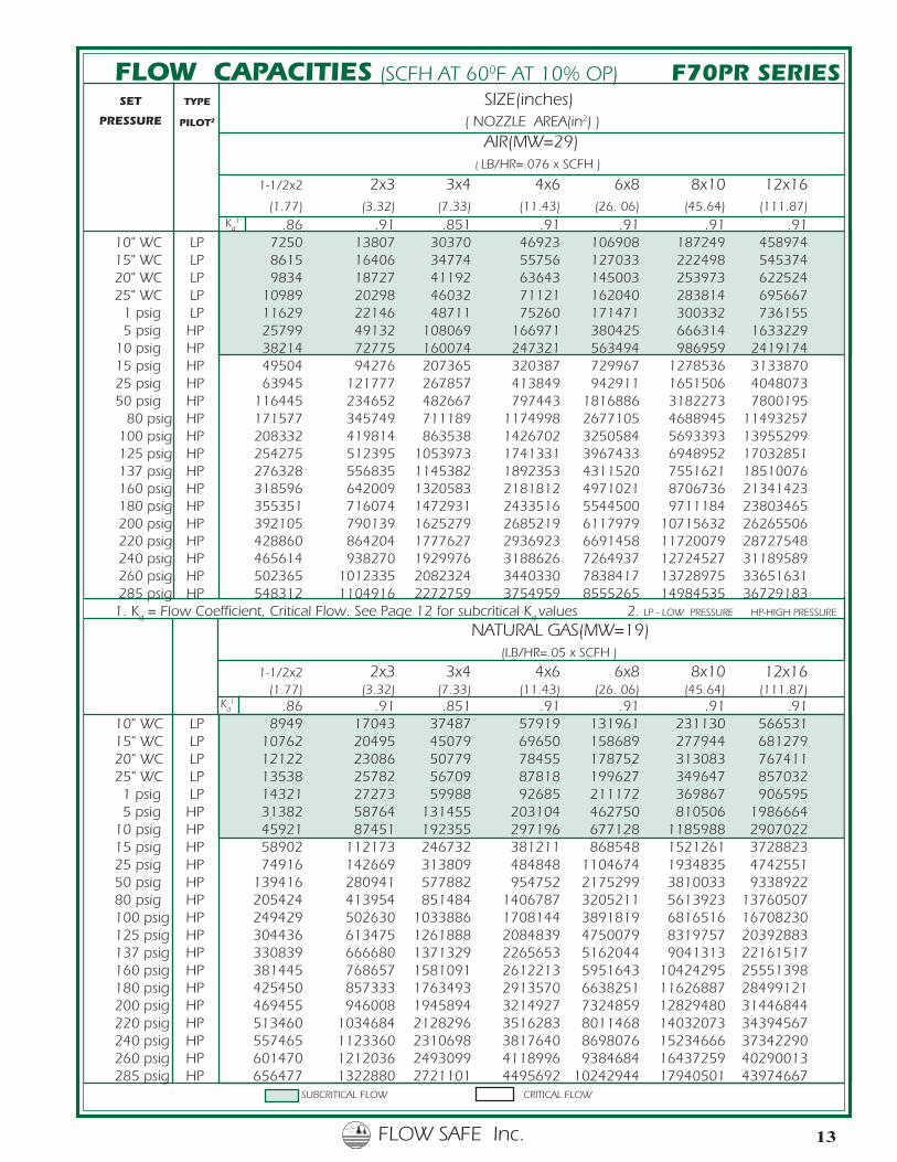
FLOW CAPACITIES (SCFH AT 600F AT 10% OP) F70PR SERIESSET TYPE SIZE(inches)
PILOT2 ( NOZZLE AREA(in2) )
AIR(MW=29) ( LB/HR=.076 x SCFH )
1-1/2x2 2x3 3x4 4x6 6x8 8x10 12x16 (1.77) (3.32) (7.33) (11.43) (26. 06) (45.64) (111.87)
.86 .91 .851 .91 .91 .91 .9110" WC LP 7250 13807 30370 46923 106908 187249 45897415" WC LP 8615 16406 34774 55756 127033 222498 54537420" WC LP 9834 18727 41192 63643 145003 253973 62252425" WC LP 10989 20298 46032 71121 162040 283814 695667
1 psig LP 11629 22146 48711 75260 171471 300332 7361555 psig HP 25799 49132 108069 166971 380425 666314 1633229
10 psig HP 38214 72775 160074 247321 563494 986959 241917415 psig HP 49504 94276 207365 320387 729967 1278536 313387025 psig HP 63945 121777 267857 413849 942911 1651506 404807350 psig HP 116445 234652 482667 797443 1816886 3182273 7800195 80 psig HP 171577 345749 711189 1174998 2677105 4688945 11493257 100 psig HP 208332 419814 863538 1426702 3250584 5693393 13955299 125 psig HP 254275 512395 1053973 1741331 3967433 6948952 17032851 137 psig HP 276328 556835 1145382 1892353 4311520 7551621 18510076 160 psig HP 318596 642009 1320583 2181812 4971021 8706736 21341423 180 psig HP 355351 716074 1472931 2433516 5544500 9711184 23803465 200 psig HP 392105 790139 1625279 2685219 6117979 10715632 26265506 220 psig HP 428860 864204 1777627 2936923 6691458 11720079 28727548 240 psig HP 465614 938270 1929976 3188626 7264937 12724527 31189589 260 psig HP 502365 1012335 2082324 3440330 7838417 13728975 33651631 285 psig HP 548312 1104916 2272759 3754959 8555265 14984535 367291831. K
d = Flow Coefficient, Critical Flow. See Page 12 for subcritical K
dvalues 2. LP - LOW PRESSURE HP-HIGH PRESSURE
NATURAL GAS(MW=19) (LB/HR=.05 x SCFH )
1-1/2x2 2x3 3x4 4x6 6x8 8x10 12x16 (1.77) (3.32) (7.33) (11.43) (26. 06) (45.64) (111.87)
.86 .91 .851 .91 .91 .91 .9110" WC LP 8949 17043 37487 57919 131961 231130 56653115" WC LP 10762 20495 45079 69650 158689 277944 68127920" WC LP 12122 23086 50779 78455 178752 313083 76741125" WC LP 13538 25782 56709 87818 199627 349647 8570321 psig LP 14321 27273 59988 92685 211172 369867 9065955 psig HP 31382 58764 131455 203104 462750 810506 1986664
10 psig HP 45921 87451 192355 297196 677128 1185988 290702215 psig HP 58902 112173 246732 381211 868548 1521261 372882325 psig HP 74916 142669 313809 484848 1104674 1934835 474255150 psig HP 139416 280941 577882 954752 2175299 3810033 933892280 psig HP 205424 413954 851484 1406787 3205211 5613923 13760507100 psig HP 249429 502630 1033886 1708144 3891819 6816516 16708230125 psig HP 304436 613475 1261888 2084839 4750079 8319757 20392883137 psig HP 330839 666680 1371329 2265653 5162044 9041313 22161517160 psig HP 381445 768657 1581091 2612213 5951643 10424295 25551398180 psig HP 425450 857333 1763493 2913570 6638251 11626887 28499121200 psig HP 469455 946008 1945894 3214927 7324859 12829480 31446844220 psig HP 513460 1034684 2128296 3516283 8011468 14032073 34394567240 psig HP 557465 1123360 2310698 3817640 8698076 15234666 37342290260 psig HP 601470 1212036 2493099 4118996 9384684 16437259 40290013285 psig HP 656477 1322880 2721101 4495692 10242944 17940501 43974667
PRESSURE
Kd
1
Kd
1
FLOW SAFE Inc.14
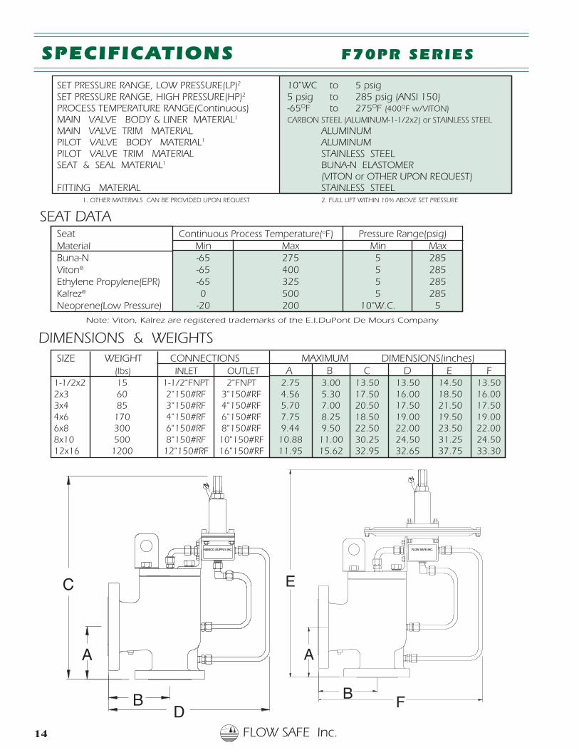
SET PRESSURE RANGE, LOW PRESSURE(LP)2 10"WC to 5 psig SET PRESSURE RANGE, HIGH PRESSURE(HP)2 5 psig to 285 psig (ANSI 150) PROCESS TEMPERATURE RANGE(Continuous) -65OF to 275OF (400OF w/VITON) MAIN VALVE BODY & LINER MATERIAL1 CARBON STEEL (ALUMINUM-1-1/2x2) or STAINLESS STEEL MAIN VALVE TRIM MATERIAL ALUMINUM PILOT VALVE BODY MATERIAL1 ALUMINUM PILOT VALVE TRIM MATERIAL STAINLESS STEEL SEAT & SEAL MATERIAL1 BUNA-N ELASTOMER
(VITON or OTHER UPON REQUEST) FITTING MATERIAL STAINLESS STEEL
1. OTHER MATERIALS CAN BE PROVIDED UPON REQUEST 2. FULL LIFT WITHIN 10% ABOVE SET PRESSURE
N
C
A
DB
NIBSCO SUPPLY INC.
E
A
B F
FLOW SAFE INC.
N
SPECIFICATIONS F70PR SERIES
Note: Viton, Kalrez are registered trademarks of the E.I.DuPont De Mours Company
SIZE WEIGHT CONNECTIONS MAXIMUM DIMENSIONS(inches) (lbs) INLET OUTLET A B C D E F
1-1/2x2 15 1-1/2"FNPT 2"FNPT 2.75 3.00 13.50 13.50 14.50 13.502x3 60 2"150#RF 3"150#RF 4.56 5.30 17.50 16.00 18.50 16.003x4 85 3"150#RF 4"150#RF 5.70 7.00 20.50 17.50 21.50 17.504x6 170 4"150#RF 6"150#RF 7.75 8.25 18.50 19.00 19.50 19.006x8 300 6"150#RF 8"150#RF 9.44 9.50 22.50 22.00 23.50 22.008x10 500 8"150#RF 10"150#RF 10.88 11.00 30.25 24.50 31.25 24.5012x16 1200 12"150#RF 16"150#RF 11.95 15.62 32.95 32.65 37.75 33.30
Seat Continuous Process Temperature(oF) Pressure Range(psig) Material Min Max Min Max Buna-N -65 275 5 285 Viton® -65 400 5 285 Ethylene Propylene(EPR) -65 325 5 285 Kalrez® 0 500 5 285 Neoprene(Low Pressure) -20 200 10"W.C. 5
SEAT DATA
DIMENSIONS & WEIGHTS
FLOW SAFE Inc. 15
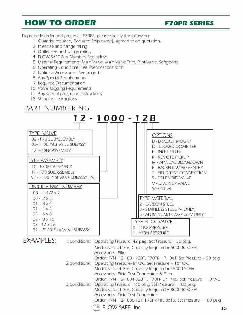
HOW TO ORDER F70PR SERIES
To properly order and process a F70PR, please specify the following: 1. Quantity required; Required Ship date(s), agreed to on quotation. 2. Inlet size and flange rating 3. Outlet size and flange rating 4. FLOW SAFE Part Number. See below. 5. Material Requirements: Main Valve, Main Valve Trim, Pilot Valve, Softgoods 6. Operating Conditions. See Specifications form. 7. Optional Accessories. See page 11 8. Any Special Requirements 9. Required Documentation10. Valve Tagging Requirements11. Any special packaging instructions12. Shipping instructions
TYPE PILOT VALVE0 - LOW PRESSURE1 - HIGH PRESSURE
TYPE MATERIAL2 - CARBON STEEL3 - STAINLESS STEEL(PV ONLY)5 - ALUMINUM(1-1/2x2 or PV ONLY)
PART NUMBERING
1 2 - 1 0 0 0 - 1 2 B
OPTIONSB - BRACKET MOUNTD - CLOSED DOME TEEF - INLET FILTERR - REMOTE PICKUPM - MANUAL BLOWDOWNP - BACKFLOW PREVENTERT - FIELD TEST CONNECTIONS - SOLENOID VALVEV - DIVERTER VALVESP-SPECIAL
TYPE VALVE 02 - F70 SUBASSEMBLY 03- F100 Pilot Valve SUBASSY
12 -F70PR ASSEMBLY
UNIQUE PART NUMBER 03 - 1-1/2 x 2
00 - 2 x 3, 01 - 3 x 4 04 - 4 x 6 05 - 6 x 8 06 - 8 x 10 08 - 12 x 16 94 - F100 Pilot Valve SUBASSY
TYPE ASSEMBLY10 - F70PR ASSEMBLY
11 - F70 SUBASSEMBLY 91 - F100 Pilot Valve SUBASSY (PV)
EXAMPLES: 1.Conditions: Operating Pressure=42 psig, Set Pressure = 50 psig,
Media:Natural Gas, Capacity Required = 500000 SCFH,Accessories: FilterOrder: P/N 12-1001-12BF, F70PR HP, 3x4, Set Pressure = 50 psig
2.Conditions: Operating Pressure=8" WC, Set Pressure = 10" WC,Media:Natural Gas, Capacity Required = 45000 SCFH,Accessories: Field Test Connection & FilterOrder: P/N 12-1004-02BFT, F70PR LP, 4x6, Set Pressure = 10"WC
3.Conditions: Operating Pressure=160 psig, Set Pressure = 180 psig,Media:Natural Gas, Capacity Required = 800000 SCFH,Accessories: Field Test ConnectionOrder: P/N 12-1006-12T, F70PR HP, 8x10, Set Pressure = 180 psig
FLOW SAFE Inc.16
“Advanced Technology for the NEW MILLENNIUM”S-3865 Taylor Road • Orchard Park, New York 14127 • 716-667-3641 • 716-667-3642 (Fax)
For more information, visit our website www.flowsafe.com
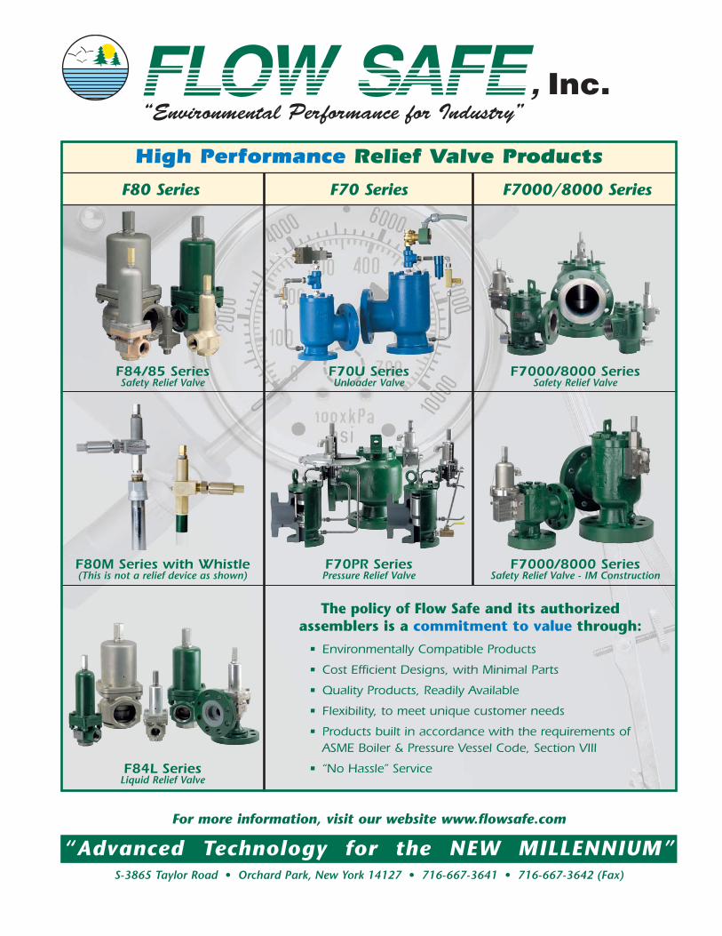
High Performance Relief Valve Products
F80 Series F70 Series F7000/8000 Series
F84/85 SeriesSafety Relief Valve
F70U SeriesUnloader Valve
F7000/8000 SeriesSafety Relief Valve
F7000/8000 SeriesSafety Relief Valve - IM Construction
F70PR SeriesPressure Relief Valve
F80M Series with Whistle(This is not a relief device as shown)
F84L SeriesLiquid Relief Valve
The policy of Flow Safe and its authorized assemblers is a commitment to value through:
• Environmentally Compatible Products
• Cost Efficient Designs, with Minimal Parts
• Quality Products, Readily Available
• Flexibility, to meet unique customer needs
• Products built in accordance with the requirements of ASME Boiler & Pressure Vessel Code, Section VIII
• “No Hassle” Service