fabrication and measurement of a flexoelectric micro
TRANSCRIPT
University of WollongongResearch Online
Australian Institute for Innovative Materials - Papers Australian Institute for Innovative Materials
2014
Fabrication and measurement of a flexoelectricmicro-pyramid compositeWenbin HuangNorth Carolina State University
Longlong ShuNorth Carolina State University
Seol Ryung KwonNorth Carolina State University
Shujun ZhangPennsylvania State University, [email protected]
Fuh Gwo YuanNorth Carolina State University
See next page for additional authors
Research Online is the open access institutional repository for the University of Wollongong. For further information contact the UOW Library:[email protected]
Publication DetailsHuang, W., Shu, L., Kwon, S., Zhang, S., Yuan, F. & Jiang, X. (2014). Fabrication and measurement of a flexoelectric micro-pyramidcomposite. AIP Advances, 4 (12), 127115-1-127115-7.
Fabrication and measurement of a flexoelectric micro-pyramid composite
AbstractA fabrication method by combining precision mechanical dicing and wet etching was developed to preparemicro-pyramid structures based on (Ba0.67Sr0.33)TiO3 ceramics. The effective piezoelectric properties offlexoelectric pyramid structures in ten micrometers scale were investigated and measured through converseflexoelectric effect. The scaling effect of the flexoelectric response was demonstrated as the structure sizeshrinks down. The results do suggest the great potential of flexoelectric micro pyramids as an alternative tolead-free piezoelectric material.
DisciplinesEngineering | Physical Sciences and Mathematics
Publication DetailsHuang, W., Shu, L., Kwon, S., Zhang, S., Yuan, F. & Jiang, X. (2014). Fabrication and measurement of aflexoelectric micro-pyramid composite. AIP Advances, 4 (12), 127115-1-127115-7.
AuthorsWenbin Huang, Longlong Shu, Seol Ryung Kwon, Shujun Zhang, Fuh Gwo Yuan, and Xiaoning Jiang
This journal article is available at Research Online: http://ro.uow.edu.au/aiimpapers/3061
Fabrication and measurement of a flexoelectric micro-pyramid compositeWenbin Huang, Longlong Shu, Seol Ryung Kwon, Shujun Zhang, Fuh-Gwo Yuan, and Xiaoning Jiang
Citation: AIP Advances 4, 127115 (2014); doi: 10.1063/1.4904024View online: https://doi.org/10.1063/1.4904024View Table of Contents: http://aip.scitation.org/toc/adv/4/12Published by the American Institute of Physics
Articles you may be interested inConverse flexoelectric coefficient f1212 in bulk Ba0.67Sr0.33TiO3Applied Physics Letters 104, 232902 (2014); 10.1063/1.4882060
Flexoelectricity in barium strontium titanate thin filmApplied Physics Letters 105, 142904 (2014); 10.1063/1.4898139
Relationship between direct and converse flexoelectric coefficientsJournal of Applied Physics 116, 144105 (2014); 10.1063/1.4897647
Piezoelectric composite based on the enhanced flexoelectric effectsApplied Physics Letters 89, 192904 (2006); 10.1063/1.2382740
Verification of the flexoelectricity in barium strontium titanate through d33 meterAIP Advances 6, 125003 (2016); 10.1063/1.4968524
Frequency dispersion of flexoelectricity in PMN-PT single crystalAIP Advances 7, 015010 (2017); 10.1063/1.4973684
AIP ADVANCES 4, 127115 (2014)
Fabrication and measurement of a flexoelectricmicro-pyramid composite
Wenbin Huang,1 Longlong Shu,1,2 Seol Ryung Kwon,1 Shujun Zhang,3Fuh-Gwo Yuan,1 and Xiaoning Jiang1,a1Department of Mechanical and Aerospace Engineering, North Carolina State University,Raleigh, NC 27695, USA2Electronic Materials Research Laboratory, Key Laboratory of the Ministry of Education &International Center for Dielectric Research, Xi’an Jiaotong University, Xi’an 710049, China3Materials Research Institute, Pennsylvania State University, University Park, PA 16802, USA
(Received 14 September 2014; accepted 27 November 2014; published online 8 December2014)
A fabrication method by combining precision mechanical dicing and wet etchingwas developed to prepare micro-pyramid structures based on (Ba0.67Sr0.33)TiO3 ce-ramics. The effective piezoelectric properties of flexoelectric pyramid structures inten micrometers scale were investigated and measured through converse flexoelectriceffect. The scaling effect of the flexoelectric response was demonstrated as the struc-ture size shrinks down. The results do suggest the great potential of flexoelectric micropyramids as an alternative to lead-free piezoelectric material. C 2014 Author(s). Allarticle content, except where otherwise noted, is licensed under a Creative CommonsAttribution 3.0 Unported License. [http://dx.doi.org/10.1063/1.4904024]
Flexoelectric effect, described as the mechanical strain gradient induced electric polarizationand electric field gradient induced mechanical strain,1 has attracted increasing research interestsin the past decade. This effect was triggered by Ma and Cross with their pioneering experimentaldemonstration of large flexoelectric coefficients in high permittivity ferroelectrics.2–4 The initialexperimental results were well matched with the theoretical prediction, revealing the linear depen-dence between the flexoelectric coefficients and the dielectric permittivity.5,6 It is noticed that thesize effect inherited from the gradient term enables flexoelectric phenomenon to be much moreenhanced in micro/nano scale compared to macro one,7,8 as interpreted in the constitutional equa-tion of the flexoelectricity
Direct: Pl = µijkl∂Sij
∂xk, Pl = f ijkl
∂Tij
∂xk
Converse: Tij = µijkl∂Ek
∂xl, Sij = f ijkl
∂Ek
∂xl
(1)
where Pl is the induced polarization, µijkl is the flexoelectric coefficient, a fourth-rank tensor Sij
is the strain and xk or xl is the axis; Tij is the mechanical stress, f ijkl is the converse flexoelectriccoefficient associated with strain and Ek is electric field.
The recent micro/nano scale flexoelectricity study are mainly concentrated on the thin film.9
The strain gradient yielded by the lattice misfit between the functional layer and the substrate layercould result in a giant electric polarization, and change the domain configuration of the ferroelectricfilm accordingly.10,11 On the other hand, large strain gradient can also be generated in the applica-tion of the atomic force microscope (AFM) tip through the mechanical writing force. Typically, upto µN level force can be applied onto the film by the AFM tip in a small circular area of 10 nm inradius. Such a high stress concentrated region could result in a huge out-of plane strain gradient, and
aElectronic mail: [email protected]
2158-3226/2014/4(12)/127115/7 4, 127115-1 ©Author(s) 2014

127115-2 Huang et al. AIP Advances 4, 127115 (2014)
thus alter the domain orientation in the film, suggesting a new avenue for non-volatile memory tech-nology.12 However, the giant flexoelectricity in non-piezoelectric nano structures are yet explicitlydeveloped, due to the fabrication and characterization challenges of ferroelectric nanostructures.
In sub-millimeter level, Fu et al. reported a gradient scaling phenomenon in microsize flexo-electric composites.13 They used mechanical dicing method to fabricate truncated pyramid struc-tures with the feature size of 50 µm and 100 µm, respectively, on BST substrates. It is wellknown that the direct piezoelectric measurement was commonly used for accessing the flexoelectricresponse of pyramid structure.14 It can be implemented directly by d33 meter which measures themechanical force induced electric current of the sample. However, such piezoelectric measurementis difficult to be exerted onto the micro truncated pyramid because of the critical sample clampcondition is always challenged when the sample size scales down. Fortunately, the converse flexo-electric measurement provides a good alternative approach through applying an AC electric voltageacross the sample and monitoring the displacement signal that is phase locked at the same drivingfrequency. Their converse measurement results suggested an approximately double-times relation-ship between the effective piezoelectric coefficients of two structures, being in good agreement withthe scaling effect of flexoelectricity.13
In order to realize the feasibility of flexoelectric composite as a promising piezoelectric struc-ture, it is necessary to further scale down the structure size of the pyramid units to obtain enhancedeffective piezoelectric properties. In the aspect of converse effect, by applying the same voltage,the nanometer size pyramid structure could generate larger displacement compared to the microm-eter level counterpart. Nevertheless, the maximum displacement that the nano scale pyramid couldachieve is quite small owing to the brittle nature of the ceramic materials, i.e. 0.7 % maximumallowable tensile strain for BST.15 In this case, in the real application of tens nanometers rangedisplacement, renders that the single layer flexoelectric pyramid structure should have the minimumheight of about 10 µm. Pyramid composites at this size level could both exhibit high piezoelectricperformance and satisfy the requirement of real application.
For fabricating pyramid of such scale, the conventional dicing saw would not offer a good avenuedue to the blade size limit. Conventionally, two measures can be considered for 10 µm range struc-ture fabrication, including top-down and bottom-up methods. Top-down method is based on lithog-raphy, electroplating and dry etching processes. This fabrication process was successfully developedby Jiang et al. for fabricating high frequency piezoelectric composites as micro-ultrasound trans-ducers.16,17 A thick layer of nickel was electroplated through the photoresist pattern, forming thehard mask for the further dry etching step, which involved the deep reactive ion etching with chlorinebased gases. However, this method is labor intensive and expensive due to the low etching rate andmultiple processing steps. On the other hand, the bottom-up method utilizes sol-gel technology toobtain the thick film.18 The patterning procedure could rely on either wet etching or dry etching.However, the problem of this method consists of the inferior properties of thick films compared withbulk material.19 To overcome the drawbacks of these fabrication methods, we developed a new fabri-cation method combining the conventional precision mechanical dicing and wet etching, in order togenerate the 10 µm range pyramid structures based on bulk BST ceramic material.
The fabrication process started from a Ba0.67Sr0.33TiO3 plate with the dimension size of 5 mm× 5 mm × 600 µm. The Curie temperature of the raw material is 21 ◦C.2,4 All measurements in thisstudy were conducted at room temperature of 23 ◦C to ensure the paraelectric phase of the materials.The top and bottom surfaces were both lapped and polished to obtain a good surface finishing. Amechanical dicing saw (Disco, DAD320, Santa Clara, CA) was employed to cut the top surface intoline arrays. The line post width and kerf width are both 30 µm, corresponding to a pitch of 60 µm.The line post depth is 40 µm. Then the sample went through a wet etching process with a recipedeveloped following the work reported on BST thin film etching using buffered oxide etchant (BOE)with strong acids, e.g. HNO3, HCl, H2SO4, as the catalysts.20–22 A solution with the composition ofBOE (10:1): HCl = 80%: 20% was prepared for wet etching of BST in our work. However, a residuelayer was observed on the surface after etching for a short period of time. This residue layer, actedas a protection layer and hindered the further etching, has yet been reported before. The crystallinestructure of residue material was examined by the X-ray diffraction (XRD) (Rigaku SmartLab). Asshown in Fig. 1, cubic structure of the BST substrate accompanied with the pattern of Ba4.67Cl1.33F8

127115-3 Huang et al. AIP Advances 4, 127115 (2014)
FIG. 1. XRD spectrum of the wet etched BST by buffered oxide acid only.
were observed on the residual material. This etching residue is not soluble in water. To remove thisresidue layer, a two-step recipe was developed by dipping the sample in a pure HCl bath for 10 sec-onds after every 5 minutes etching in BOE based etchant. It was found that the residue material canbe dissolved instantly in HCl solution, similar to the PZT wet etching process.23 According to thisrecipe, the etching rate was measured to be 100 nm/min and a clean surface finish can be achieved.Two samples were prepared with one etched for 20 minutes and the other for 30 minutes. A thirdsample was used as a reference sample without dicing or etching treatment. The cross sections oftwo samples were captured by scanning electron microscope (SEM) (JEOL 2000FX) as shown inFig. 2. Wet etching is known to be isotropic for ceramic materials. The convex shape corner can beetched faster due to the large exposed area to the etchant, while the concave corner exhibits a sloweretching rate because of the small exposed area. Also, the etchant in the groove area has less agitationcompared to the top surfaces. All these factors enable wet etching to generate pyramid shapes out ofthe diced straight line post structures. Note that the observed cracks, mainly caused by the handlingimpact, only existed near the edge of the samples. The main parts of the structure were intact withsmooth pyramid shape. The dimension of the two pyramid structures were listed in Table I.
(a) (b)
FIG. 2. SEM photographs of cross section of the fabricated pyramid structures with different sizes (areas in black are filledepoxy).

127115-4 Huang et al. AIP Advances 4, 127115 (2014)
TABLE I. Dimension of BST samples and calculated effective d33.
SampleEtching time
(minutes)Top width a1
(µm)Bottom width a2
(µm)Height t
(µm) Estimated d33 (pm/V)
BST I 20 18 45 35 31BST II 30 10 40 25 87
In order to generate an electric field gradient along the pyramid structure, the sidewalls of thepyramid should be protected from the electrode coverage. Epoxy (Epo-Tek 301, Epoxy Technology,Billerica, MA) was casted onto the pyramids to fill the kerfs. The residual epoxy on the top sur-face was removed by lapping. Top and bottom surfaces of two samples were coated with Ti/Au(10 nm/100 nm) as electrodes through electron beam evaporation.
In principle, the effective piezoelectric constant of the pyramid layer can be calculated as
d33 =µ11
tc11
a2 − a1
a1(2)
where a1 and a2 are the top and bottom width, t is the height and c11 is the elastic constant of BSTwith the value of 1.66 × 10¹¹ N/m2. The schematic view of the 1D pyramid composite is displayed inFig. 3 with the critical feature sizes. The µ11 of Ba0.67Sr0.33TiO3 has been measured by Cross et al. tobe 120 µC/m.4 Based on the dimension and the material properties, the effective d33 of two sampleswere calculated to be 31 pm/V and 87 pm/V, respectively.
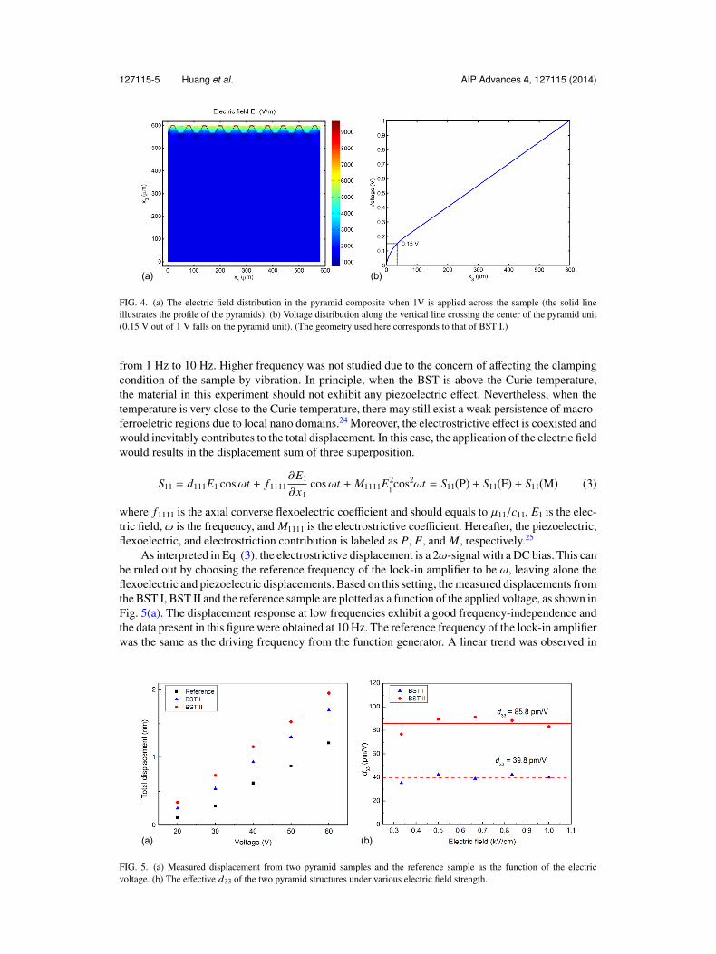
It is worth mentioning that owing to the existence of the substrate layer, only a portion of theelectric voltage would fall upon the pyramid layer. To attain the exact amount of voltage percent-ages on the pyramid, COMSOL Multiphysics was used to simulate the electric field distribution inthe composite structure. As shown in Fig. 4, the relative dielectric constants of BST and the polymerare set as 12000 and 5, respectively. 1 V voltage was applied across the whole sample (geometryadopted here corresponds to BST I), and electric field gradient can be apparently observed in Fig.4(a). The percentage of the voltage falling on the pyramid is about 15%. For the BST II, the partfalling on the pyramid is 13% percent.
The measurement setup was laid down on a floating optical table (Newport, ATS, Irvine, CA)to eliminate the vibrational noise. The AC voltage was generated by a power amplifier (Trek, 2220,Lockport, NY) under the excitation from a function generator (Tectronix, AFG3101, Lake Mary, FL).To measure the small flexoelectric displacement, the bottom surface of the sample was clamped onthe table. The axial deformation was measured using a high resolution (<10 pm) laser vibrometer(Polytec, OFV-5000, Irvine, CA) and a lock-in amplifier (Stanford Research System, SR830, Sun-nyvale, CA). The applied voltage was ranged from 20 V to 60 V, in order to avoid the saturation ofthe relative dielectric permittivity of BST at high electric field.14 The excitation frequency was swept
FIG. 3. Schematic view of the 1D pyramid composite.
127115-5 Huang et al. AIP Advances 4, 127115 (2014)
(a) (b)
FIG. 4. (a) The electric field distribution in the pyramid composite when 1V is applied across the sample (the solid lineillustrates the profile of the pyramids). (b) Voltage distribution along the vertical line crossing the center of the pyramid unit(0.15 V out of 1 V falls on the pyramid unit). (The geometry used here corresponds to that of BST I.)
from 1 Hz to 10 Hz. Higher frequency was not studied due to the concern of affecting the clampingcondition of the sample by vibration. In principle, when the BST is above the Curie temperature,the material in this experiment should not exhibit any piezoelectric effect. Nevertheless, when thetemperature is very close to the Curie temperature, there may still exist a weak persistence of macro-ferroeletric regions due to local nano domains.24 Moreover, the electrostrictive effect is coexisted andwould inevitably contributes to the total displacement. In this case, the application of the electric fieldwould results in the displacement sum of three superposition.
S11 = d111E1 cosωt + f1111∂E1
∂x1cosωt + M1111E2
1cos2ωt = S11(P) + S11(F) + S11(M) (3)
where f1111 is the axial converse flexoelectric coefficient and should equals to µ11/c11, E1 is the elec-tric field, ω is the frequency, and M1111 is the electrostrictive coefficient. Hereafter, the piezoelectric,flexoelectric, and electrostriction contribution is labeled as P, F, and M , respectively.25
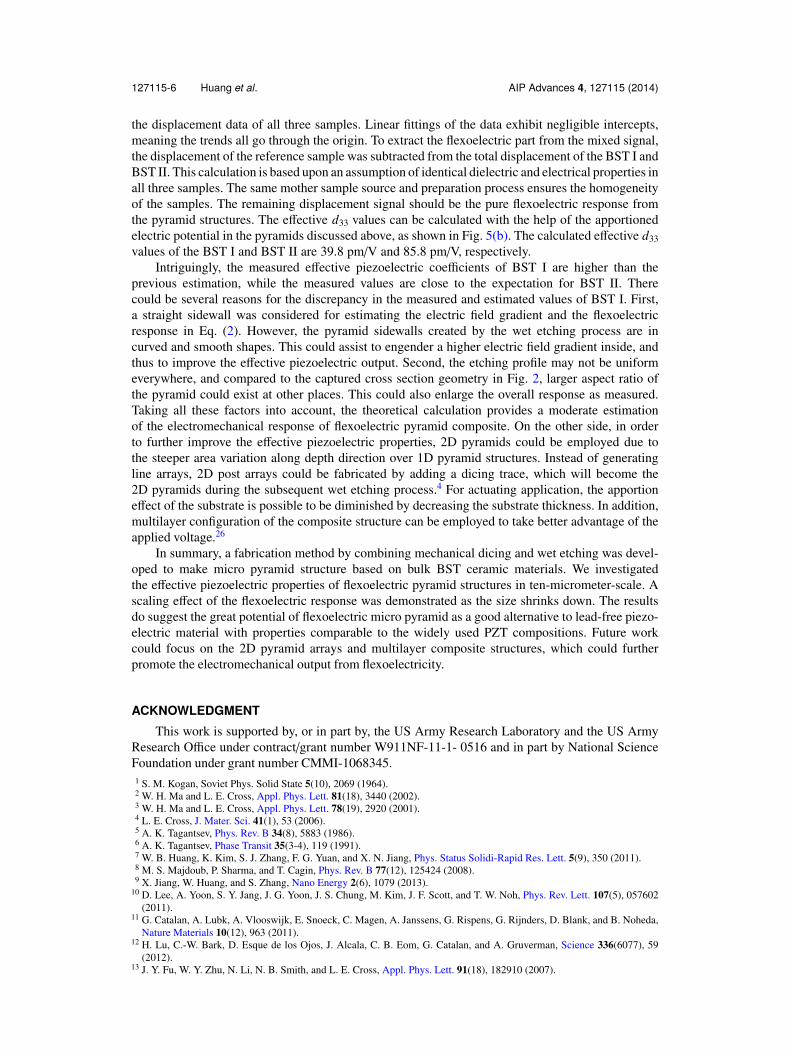
As interpreted in Eq. (3), the electrostrictive displacement is a 2ω-signal with a DC bias. This canbe ruled out by choosing the reference frequency of the lock-in amplifier to be ω, leaving alone theflexoelectric and piezoelectric displacements. Based on this setting, the measured displacements fromthe BST I, BST II and the reference sample are plotted as a function of the applied voltage, as shown inFig. 5(a). The displacement response at low frequencies exhibit a good frequency-independence andthe data present in this figure were obtained at 10 Hz. The reference frequency of the lock-in amplifierwas the same as the driving frequency from the function generator. A linear trend was observed in
(a) (b)
FIG. 5. (a) Measured displacement from two pyramid samples and the reference sample as the function of the electricvoltage. (b) The effective d33 of the two pyramid structures under various electric field strength.
127115-6 Huang et al. AIP Advances 4, 127115 (2014)
the displacement data of all three samples. Linear fittings of the data exhibit negligible intercepts,meaning the trends all go through the origin. To extract the flexoelectric part from the mixed signal,the displacement of the reference sample was subtracted from the total displacement of the BST I andBST II. This calculation is based upon an assumption of identical dielectric and electrical properties inall three samples. The same mother sample source and preparation process ensures the homogeneityof the samples. The remaining displacement signal should be the pure flexoelectric response fromthe pyramid structures. The effective d33 values can be calculated with the help of the apportionedelectric potential in the pyramids discussed above, as shown in Fig. 5(b). The calculated effective d33values of the BST I and BST II are 39.8 pm/V and 85.8 pm/V, respectively.
Intriguingly, the measured effective piezoelectric coefficients of BST I are higher than theprevious estimation, while the measured values are close to the expectation for BST II. Therecould be several reasons for the discrepancy in the measured and estimated values of BST I. First,a straight sidewall was considered for estimating the electric field gradient and the flexoelectricresponse in Eq. (2). However, the pyramid sidewalls created by the wet etching process are incurved and smooth shapes. This could assist to engender a higher electric field gradient inside, andthus to improve the effective piezoelectric output. Second, the etching profile may not be uniformeverywhere, and compared to the captured cross section geometry in Fig. 2, larger aspect ratio ofthe pyramid could exist at other places. This could also enlarge the overall response as measured.Taking all these factors into account, the theoretical calculation provides a moderate estimationof the electromechanical response of flexoelectric pyramid composite. On the other side, in orderto further improve the effective piezoelectric properties, 2D pyramids could be employed due tothe steeper area variation along depth direction over 1D pyramid structures. Instead of generatingline arrays, 2D post arrays could be fabricated by adding a dicing trace, which will become the2D pyramids during the subsequent wet etching process.4 For actuating application, the apportioneffect of the substrate is possible to be diminished by decreasing the substrate thickness. In addition,multilayer configuration of the composite structure can be employed to take better advantage of theapplied voltage.26
In summary, a fabrication method by combining mechanical dicing and wet etching was devel-oped to make micro pyramid structure based on bulk BST ceramic materials. We investigatedthe effective piezoelectric properties of flexoelectric pyramid structures in ten-micrometer-scale. Ascaling effect of the flexoelectric response was demonstrated as the size shrinks down. The resultsdo suggest the great potential of flexoelectric micro pyramid as a good alternative to lead-free piezo-electric material with properties comparable to the widely used PZT compositions. Future workcould focus on the 2D pyramid arrays and multilayer composite structures, which could furtherpromote the electromechanical output from flexoelectricity.
ACKNOWLEDGMENTThis work is supported by, or in part by, the US Army Research Laboratory and the US Army
Research Office under contract/grant number W911NF-11-1- 0516 and in part by National ScienceFoundation under grant number CMMI-1068345.1 S. M. Kogan, Soviet Phys. Solid State 5(10), 2069 (1964).2 W. H. Ma and L. E. Cross, Appl. Phys. Lett. 81(18), 3440 (2002).3 W. H. Ma and L. E. Cross, Appl. Phys. Lett. 78(19), 2920 (2001).4 L. E. Cross, J. Mater. Sci. 41(1), 53 (2006).5 A. K. Tagantsev, Phys. Rev. B 34(8), 5883 (1986).6 A. K. Tagantsev, Phase Transit 35(3-4), 119 (1991).7 W. B. Huang, K. Kim, S. J. Zhang, F. G. Yuan, and X. N. Jiang, Phys. Status Solidi-Rapid Res. Lett. 5(9), 350 (2011).8 M. S. Majdoub, P. Sharma, and T. Cagin, Phys. Rev. B 77(12), 125424 (2008).9 X. Jiang, W. Huang, and S. Zhang, Nano Energy 2(6), 1079 (2013).
10 D. Lee, A. Yoon, S. Y. Jang, J. G. Yoon, J. S. Chung, M. Kim, J. F. Scott, and T. W. Noh, Phys. Rev. Lett. 107(5), 057602(2011).
11 G. Catalan, A. Lubk, A. Vlooswijk, E. Snoeck, C. Magen, A. Janssens, G. Rispens, G. Rijnders, D. Blank, and B. Noheda,Nature Materials 10(12), 963 (2011).
12 H. Lu, C.-W. Bark, D. Esque de los Ojos, J. Alcala, C. B. Eom, G. Catalan, and A. Gruverman, Science 336(6077), 59(2012).
13 J. Y. Fu, W. Y. Zhu, N. Li, N. B. Smith, and L. E. Cross, Appl. Phys. Lett. 91(18), 182910 (2007).

127115-7 Huang et al. AIP Advances 4, 127115 (2014)
14 J. Y. Fu, W. Y. Zhu, N. Li, and L. E. Cross, J. Appl. Phys. 100(2), 024112 (2006).15 T. M. Shaw, Z. Suo, M. Huang, E. Liniger, R. B. Laibowitz, and J. D. Baniecki, Appl. Phys. Lett. 75(14), 2129 (1999).16 X. Jiang, J. R. Yuan, A. Cheng, K. Snook, P. J. Cao, P. W. Rehrig, W. S. Hackenberger, G. Lavalelle, X. Geng, and T. R.
Shrout, in 2006 IEEE Ultrasonics Symposium, Vols 1-5, Proceedings (IEEE, New York, 2006) pp. 922.17 J. R. Yuan, X. Jiang, C. Pei-Jie, A. Sadaka, R. Bautista, K. Snook, and P. W. Rehrig, Ultrasonics Symposium, 2006 (IEEE,
2006).18 L.-P. Wang, R. Wolf, Q. Zhou, S. Trolier-McKinstry, and R. Davis, MRS Proceedings (2000).19 S. U. Adikary and H. L. W. Chan, Thin Solid Films 424(1), 70 (2003).20 T.-L. Ren, X.-N. Wang, J.-S. Liu, H.-J. Zhao, T.-Q. Shao, L.-T. Liu, and Z.-J. Li, J. Phys. D: Appl. Phys. 35(9), 923 (2002).21 R. Zhang, C. Yang, A. Yu, B. Wang, H. Tang, H. Chen, and J. Zhang, Appl. Surf. Sci. 254(21), 6697 (2008).22 T. Zhang, H. Huang, and R. Chen, Ferroelectrics 410(1), 137 (2010).23 K. Zheng, J. Lu, and J. Chu, Jpn. J. Appl. Phys. 43(6S), 3934 (2004).24 M. Roth, E. Mojaev, E. Dul’kin, P. Gemeiner, and B. Dkhil, Phys. Rev. Lett. 98(26), 265701 (2007).25 L. Shu, W. Huang, S. R. Kwon, Z. Wang, F. Li, X. Wei, S. Zhang, M. Lanagan, X. Yao, and X. Jiang, Appl. Phys. Lett.
104(23), 232902 (2014).26 B. J. Chu, W. Y. Zhu, N. Li, and L. E. Cross, J. Appl. Phys. 106(10), 104109 (2009).