factors affecting ground-water exchange and catchment size ... · copies of this report can be...
TRANSCRIPT
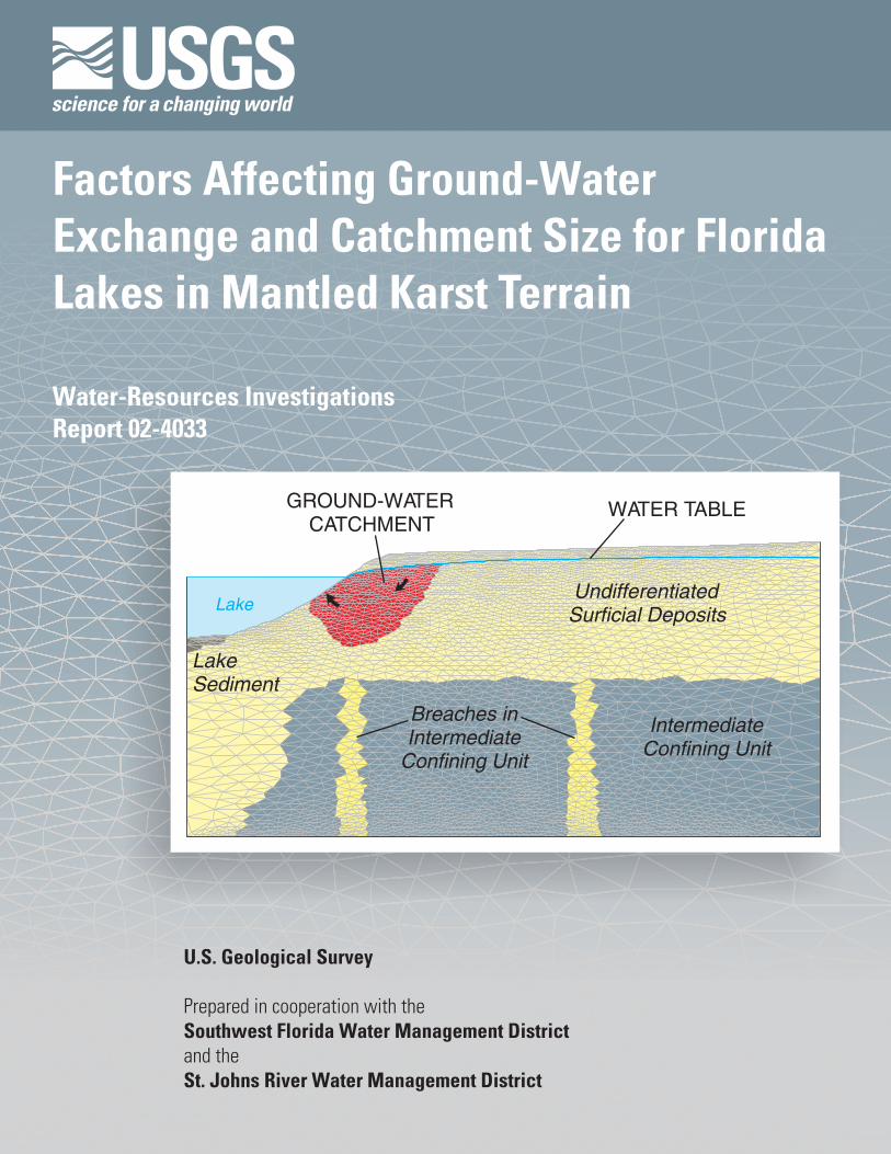
Lake
IntermediateConfining Unit
Breaches in Intermediate
Confining Unit
UndifferentiatedSurficial Deposits
Lake Sediment
GROUND-WATER CATCHMENT
WATER TABLE
Factors Affecting Ground-Water Exchange and Catchment Size for Florida Lakes in Mantled Karst Terrain
U.S. Geological Survey
Prepared in cooperation with the Southwest Florida Water Management District and theSt. Johns River Water Management District
Water-Resources InvestigationsReport 02-4033

Factors Affecting Ground-Water Exchange and Catchment Size for Florida Lakes in Mantled Karst Terrain
By T.M. Lee
U.S. GEOLOGICAL SURVEYWater-Resources Investigations Report 02-4033
Prepared in cooperation with theSOUTHWEST FLORIDA WATER MANAGEMENT DISTRICTand theST. JOHNS RIVER WATER MANAGEMENT DISTRICT
Tallahassee, Florida2002

Copies of this report can be purchased from:
U.S. Geological SurveyBranch of Information ServicesBox 25286Denver, CO 80225-0286888-ASK-USGS
The use of firm, trade, and brand names in this report is for identification purposes only and does not constitute endorsement by the U.S. Geological Survey.
For additional informationwrite to:
District ChiefU.S. Geological SurveySuite 3015227 N. Bronough StreetTallahassee, FL 32301
Additional information about water resources in Florida is available on the World Wide Web at http://fl.water.usgs.gov
U.S. DEPARTMENT OF THE INTERIORGALE A. NORTON, Secretary
U.S. GEOLOGICAL SURVEYCHARLES G. GROAT, Director

CONTENTS
Abstract.................................................................................................................................................................................. 1Introduction ........................................................................................................................................................................... 1
Purpose and Scope ....................................................................................................................................................... 2Acknowledgments ....................................................................................................................................................... 2Background.................................................................................................................................................................. 3
Physical Characterization of Lake Basins ............................................................................................................................. 5Methods ....................................................................................................................................................................... 7Physical Characteristics ............................................................................................................................................... 8
Topography and Ground-Water Flow Patterns.................................................................................................. 20Hydrogeologic Framework ................................................................................................................................ 21
Numerical Modeling of Ground-Water Flow ........................................................................................................................ 28Methods ....................................................................................................................................................................... 28
Radial Models .................................................................................................................................................... 29Model Boundaries.............................................................................................................................................. 32Limits to Hypothetical Steady-State Simulations .............................................................................................. 32Limits to Hypothetical Transient Simulations ................................................................................................... 33
Steady-State Simulation Results.................................................................................................................................. 33Initial Lake Basin Model ................................................................................................................................... 33Effect of Recharge Rate ..................................................................................................................................... 35Effect of Basin Size ........................................................................................................................................... 36Effect of Surficial Aquifer Conductivity ........................................................................................................... 37Effect of Intermediate Confining Unit............................................................................................................... 38Effect of Lake Sediment .................................................................................................................................... 41Effect of Upper Floridan Aquifer Boundary Condition..................................................................................... 41Effect of Lake Stage .......................................................................................................................................... 42Effect of Lake Depth.......................................................................................................................................... 43
Transient Simulation Results ....................................................................................................................................... 46Factors Affecting Ground-Water Exchange and Catchment Size ......................................................................................... 48
Catchment Size in Mantled Karst Terrain.................................................................................................................... 49Hydrogeologic Controls on Ground-Water Exchange................................................................................................. 50
Summary and Conclusions .................................................................................................................................................... 50References ............................................................................................................................................................................. 52
FIGURES
1. Schematic showing generalized hydrogeologic section through a Florida ridge lake in a flow-through setting................................................................................................................................................. 3
2-14. Maps showing:2. Locations of the study lakes in Florida ........................................................................................................... 63. Topographic setting and general direction of ground-water flow in the surficial aquifer around
Lake Annie ...................................................................................................................................................... 94. Topographic setting of Lake Barco, general direction of ground-water flow in the surrounding
surficial aquifer, and the simulated steady-state ground-water catchment ..................................................... 105. Topographic setting of Lake Five-O, general direction of ground-water flow in the surrounding
surficial aquifer, and the simulated steady-state ground-water catchment ..................................................... 116. Topographic setting and general direction of ground-water flow in the surficial aquifer around
Lake George and Grassy Lake ........................................................................................................................ 12
Contents III

7. Topographic setting and general direction of ground-water flow in the surficial aquifer around Halfmoon Lake ............................................................................................................................................... 13
8. Topographic setting and general direction of ground-water flow in the surficial aquifer around Lake Hollingsworth ........................................................................................................................................ 14
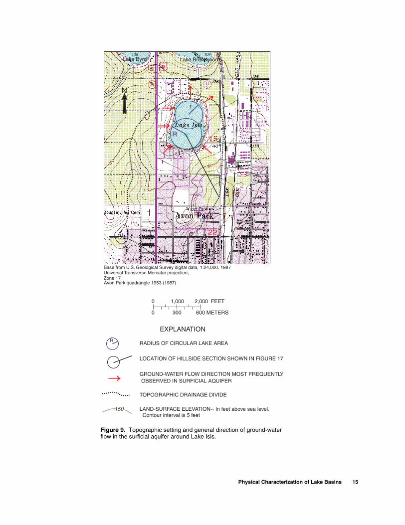
9. Topographic setting and general direction of ground-water flow in the surficial aquifer around Lake Isis.......................................................................................................................................................... 15
10. Topographic setting and general direction of ground-water flow in the surficial aquifer aroundLake Lucerne .................................................................................................................................................. 16
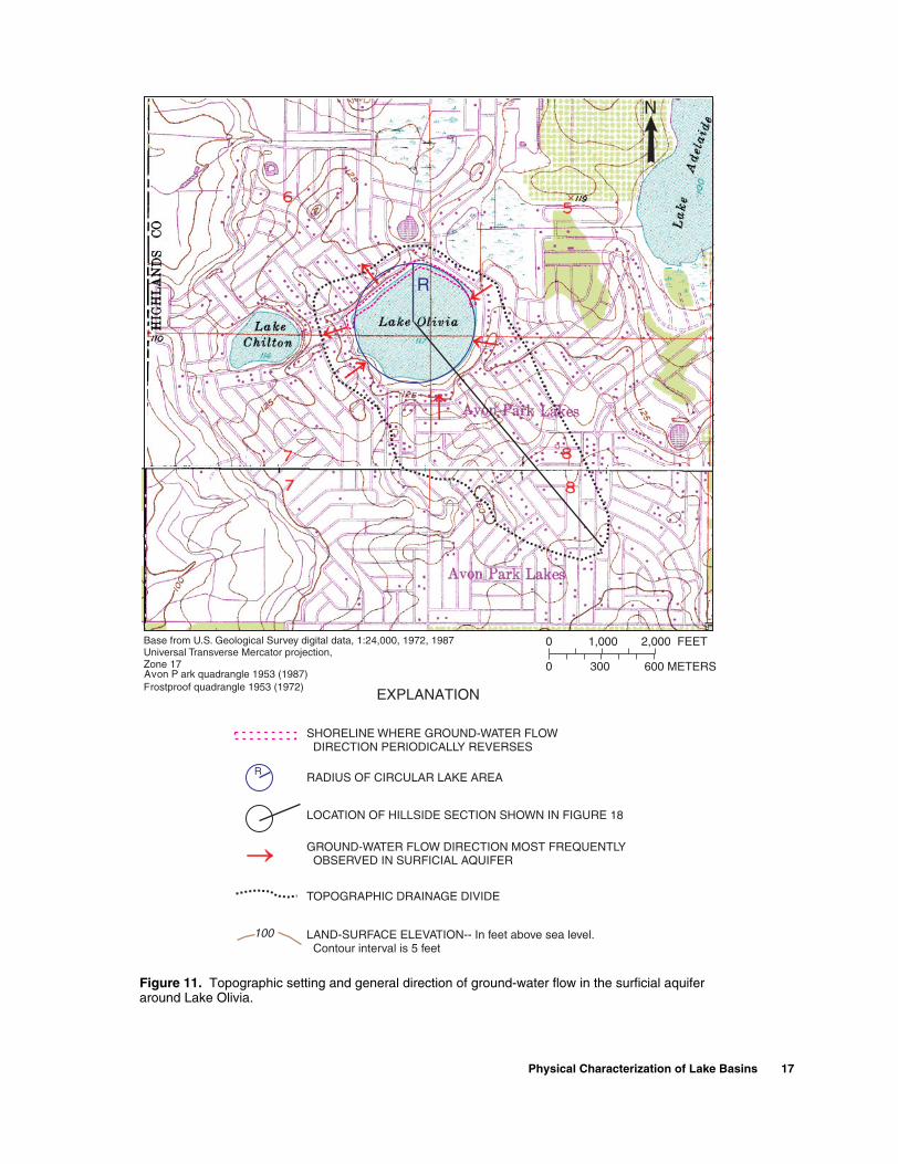
11. Topographic setting and general direction of ground-water flow in the surficial aquifer around Lake Olivia ..................................................................................................................................................... 17
12. Topographic setting and general direction of ground-water flow in the surficial aquifer around Round Lake and Saddle Blanket Lakes .......................................................................................................... 18
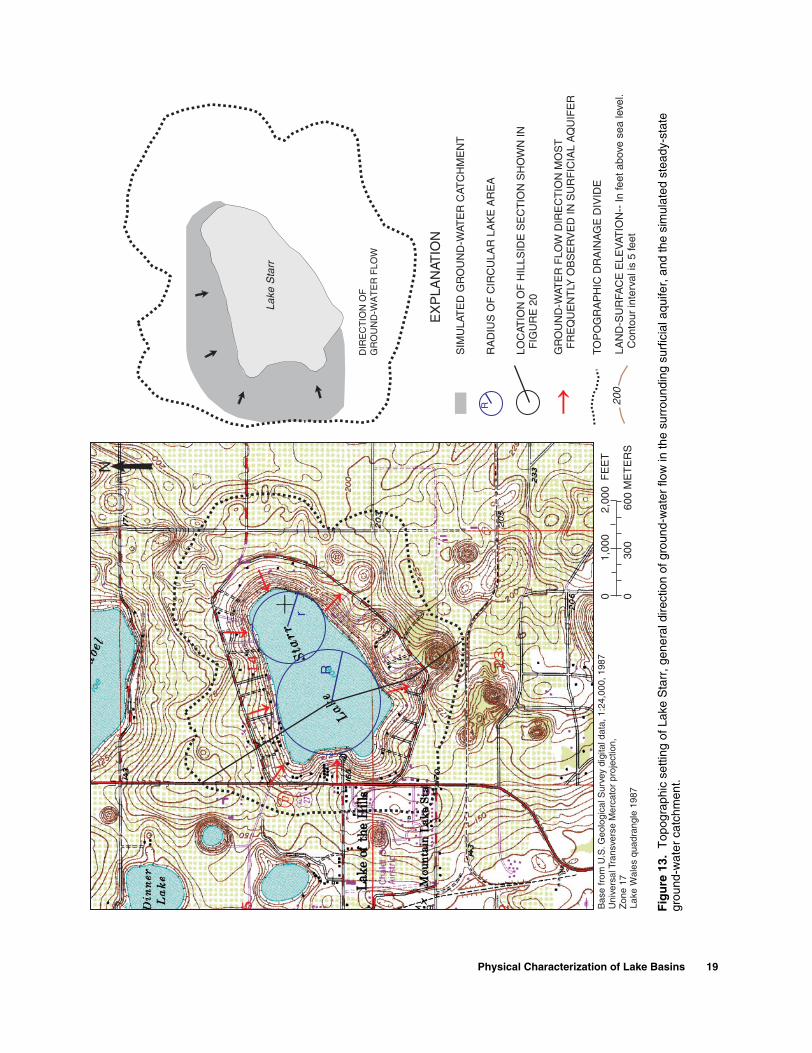
13. Topographic setting of Lake Starr, general direction of ground-water flow in the surrounding surficial aquifer, and the simulated steady-state ground-water catchment ..................................................... 19
14. Topographic setting and general direction of ground-water flow in the surficial aquifer around Swim Lake...................................................................................................................................................... 20
15-20. Cross sections showing simplified hydrogeologic sections along hillsides in the topographic basins of:15. Lake Annie and Lake Barco ........................................................................................................................... 2216. Lake Five-O, Lake George, Grassy Lake, and Halfmoon Lake ..................................................................... 2317. Lake Hollingsworth and Lake Isis.................................................................................................................. 2418. Lake Lucerne and Lake Olivia ....................................................................................................................... 2519. Round Lake and Saddle Blanket Lakes .......................................................................................................... 2620. Lake Starr and Swim Lake ............................................................................................................................. 27
21. Graph showing relation of the head difference between the lake and Upper Floridan aquifer to mantle thickness near lake and to lake elevation ................................................................................................................ 28
22-24. Schematics of:22. The initial lake basin model .................................................................................................................................... 2923. The hillsides used for transient simulations ............................................................................................................ 3124. Simulation results for the initial lake basin model: areal view of basin showing the location of the
ground-water catchment to the lake, and radial view showing the simulated water table and location of the ground-water catchment................................................................................................................................ 34
25. Graph showing ground-water flow distribution along the lakebed for the initial lake basin model ....................... 3526-29. Bar charts showing simulated ground-water inflow and leakage rates, and catchment sizes for modeled
lakes with different:26. Recharge rates................................................................................................................................................. 3527. Size basins ...................................................................................................................................................... 3628. Horizontal hydraulic conductivity (Kh) values in the surficial aquifer........................................................... 3729. Vertical hydraulic conductivity (Kv) values in the intermediate confining unit surrounding
the lake............................................................................................................................................................ 3830. Graph showing ground-water flow distribution along the lakebed for different vertical hydraulic
conductivity (Kv) values in the intermediate confining unit surrounding the lake ................................................. 3931. Schematic showing different size collapse features beneath lake and various arrangements of lake
sediment used in ground-water flow simulations.................................................................................................... 3932-36. Bar charts showing:
32. Simulated ground-water inflow and leakage rates for modeled lakes with different size collapse features beneath the lake................................................................................................................................. 40
33. Simulated ground-water inflow and leakage rates and catchment sizes for modeled lakes with breaches in the intermediate confining unit surrounding the lake.................................................................. 40
34. Simulated ground-water inflow and leakage rates for modeled lakes with different arrangements of lake sediment.............................................................................................................................................. 41
35. Simulated ground-water inflow and leakage rates and catchment sizes for modeled lakes with different head values in the Upper Floridan aquifer ....................................................................................... 42
36. Simulated ground-water inflow and leakage rates and catchment sizes for modeled lakes maintained at different lake stages ................................................................................................................. 43
37. Schematic showing different lake depths and surficial aquifer thicknesses used in model simulations................. 44
IV Contents
38. Bar chart showing simulated ground-water inflow and leakage rates, and catchment sizes for modeled lakes of different depths with the surficial aquifer thickness near lake equal to 41 feet and 57.4 feet ................................................................................................................................................... 45
39-40. Graphs showing:39. Transient ground-water inflow to modeled lakes for basins with different unsaturated zone thicknesses..... 4740. Relation between lake size, the distance offshore that ground-water inflow occurs, and the percentage
of the lakebed receiving ground-water inflow................................................................................................ 49
TABLES
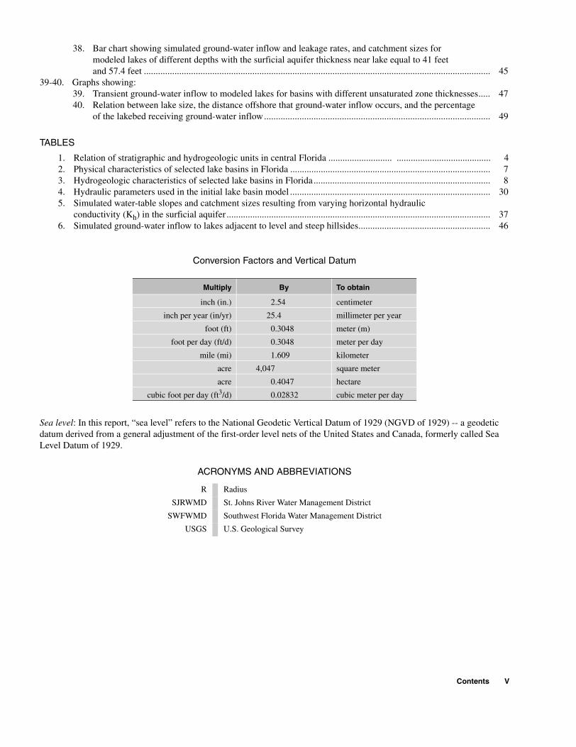
1. Relation of stratigraphic and hydrogeologic units in central Florida ........................... ........................................ 42. Physical characteristics of selected lake basins in Florida ..................................................................................... 73. Hydrogeologic characteristics of selected lake basins in Florida ........................................................................... 84. Hydraulic parameters used in the initial lake basin model ..................................................................................... 305. Simulated water-table slopes and catchment sizes resulting from varying horizontal hydraulic
conductivity (Kh) in the surficial aquifer ................................................................................................................ 376. Simulated ground-water inflow to lakes adjacent to level and steep hillsides........................................................ 46
Conversion Factors and Vertical Datum
Sea level: In this report, “sea level” refers to the National Geodetic Vertical Datum of 1929 (NGVD of 1929) -- a geodetic datum derived from a general adjustment of the first-order level nets of the United States and Canada, formerly called Sea Level Datum of 1929.
ACRONYMS AND ABBREVIATIONS
Multiply By To obtain
inch (in.) 2.54 centimeter
inch per year (in/yr) 25.4 millimeter per year
foot (ft) 0.3048 meter (m)
foot per day (ft/d) 0.3048 meter per day
mile (mi) 1.609 kilometer
acre 4,047 square meter
acre 0.4047 hectare
cubic foot per day (ft3/d) 0.02832 cubic meter per day
R Radius
SJRWMD St. Johns River Water Management District
SWFWMD Southwest Florida Water Management District
USGS U.S. Geological Survey
Contents V

VI Contents

Factors Affecting Ground-Water Exchange and Catchment Size for Florida Lakes in Mantled Karst TerrainBy T.M. Lee
In the mantled karst terrain of Florida, the size of the catchment delivering ground-water inflow to lakes is often considerably smaller than the topographically defined drainage basin. The size is determined by a balance of factors that act individually to enhance or diminish the hydraulic connection between the lake and the adjacent surficial aquifer, as well as the hydraulic connec-tion between the surficial aquifer and the deeper limestone aquifer. Factors affecting ground-water exchange and the size of the ground-water catchment for lakes in mantled karst terrain were examined by: (1) reviewing the physical and hydrogeological characteristics of 14 Florida lake basins with available ground-water inflow esti-mates, and (2) simulating ground-water flow in hypothetical lake basins. Variably-saturated flow modeling was used to simulate a range of physical and hydrogeologic factors observed at the 14 lake basins. These factors included: recharge rate to the surficial aquifer, thickness of the unsaturated zone, size of the topographically defined basin, depth of the lake, thickness of the surficial aquifer, hydraulic conductivity of the geologic units, the location and size of karst subsidence features beneath and onshore of the lake, and the head in the Upper Floridan aquifer.
Catchment size and the magnitude of ground-water inflow increased with increases in recharge rate to the surficial aquifer, the size of the topographically defined basin, hydraulic
ABSTRACT
conductivity in the surficial aquifer, the degree of confinement of the deeper Upper Floridan aquifer, and the head in the Upper Floridan aquifer. The catchment size and magnitude of ground-water inflow increased with decreases in the number and size of karst subsidence features in the basin, and the thickness of the unsaturated zone near the lake. Model results, although qualitative, provided insights into: (1) the types of lake basins in man-tled karst terrain that have the potential to generate small and large amounts of ground-water inflow, and (2) the location of ground-water catchments that could be managed to safeguard lake water quality. Knowledge of how ground-water catch-ments are related to lakes could be used by water-resource managers to recommend setback dis-tances for septic tank drain fields, agricultural land uses, and other land-use practices that contribute nutrients and major ions to lakes.INTRODUCTION
Ground-water interactions with lakes in man-tled karst terrain are a fundamental concern to water managers interested in protecting and developing water resources. In Florida, more than 7,000 lakes are situated in a layer or mantle of sand and clay that blan-kets an extensive and highly productive limestone aquifer, the Upper Floridan aquifer. Many are seepage lakes with basins that lack natural streams, and all rely to varying degrees on ground water to convey inflow and outflow between the lake and surrounding aqui-fers. Understanding the location and size of the catch-ment contributing ground-water inflow to lakes is particularly important because all of the ground water
Abstract 1
within the catchment eventually flows into the lake. Ground water from the surficial aquifer system flows into the lake and helps to sustain lake stage by replac-ing the lake water that leaks to the deeper limestone aquifer. Ground-water inflow also helps offset lake evaporation losses, which can exceed rainfall in west-central Florida lakes (Swancar and others, 2000). Fer-tilizers and other solutes applied within catchment areas can enter the lakes through ground-water inflow and have a measurable effect on the water quality of lakes in Florida (Eilers and others, 1988; Lee and Sacks, 1991; Pollman and others, 1991; Stauffer, 1991; Sacks and others, 1998).
Results of water, solute, and isotope mass bal-ance studies of 14 lakes in Florida suggest that the amount of annual ground-water inflow to lakes can vary widely, even for lakes of similar size and apparent physical setting (Pollman and others, 1991; Sacks and others, 1998). In addition, the size of ground-water catchments can vary substantially from lake to lake (Grubbs, 1995; Lee, 1996; Amy Swancar and T.M. Lee, USGS, written commun., 2002). The effects of physical setting on ground-water exchange have been described in detail in a few basin-scale lake studies that combine hydrogeologic descriptions with water budgets and ground-water flow modeling (Lee and others, 1991; Grubbs, 1995; Lee and Swancar, 1997, Swancar and others, 2000). However, a more general quantitative framework is needed to anticipate the ground-water interactions in the larger population of lakes.
Modeling the distinctive settings of Florida lakes can aid in characterizing the principle types of flow regimes within the overall lake population. Numerical modeling studies of hypothetical lake basins have been used to characterize the ground-water flow regimes of lakes in the glacial terrain of North America (Winter, 1976, 1978; Anderson and Munter, 1981; Winter and Pfannkuch, 1984), and the coastal plain near Perth, Western Australia (Nield and others, 1994; Townley and Trefry, 2000). Because of essential differences in geology and climate, however, it can be difficult or impossible to extrapolate these results to Florida lakes in mantled karst terrain. The U.S. Geological Survey began a study in 1998 in coop-eration with the Southwest Florida Water Management District and the St. Johns River Water Management District to examine the effect of recharge and basin hydrogeologic characteristics on the magnitude of ground-water exchange and catchment sizes for lakes in the mantled karst terrain of Florida.
Purpose and Scope
This report presents the results of numerical ground-water flow modeling of hypothetical lake basins with a range of basin characteristics typical of mantled karst terrain. In this report, steady-state and transient ground-water flow modeling is used to simu-late how recharge, hydrogeologic setting, and basin geometry affect the size of the ground-water catch-ment and the magnitude of ground-water inflow. Mod-eling results are summarized and used to make generalizations about the potential for different arche-typal lake basins to generate ground-water inflow to Florida lakes.
Ground-water flow is simulated using a variably saturated flow model. Most of the model simulations assume steady-state conditions, but transient simula-tions are used to explore how the timing of recharge fluxes may affect ground-water interactions with the lake. The idealized lake basin geometries and hydro-geologic data used in the modeling relied on physical characteristics summarized for 14 lake basins in ridge areas of Florida. Estimates of the ground-water inflow to these lakes and data on their hydrogeologic settings are available in published reports. Model simulations of hypothetical lakes examine the effect of the follow-ing characteristics on the ground-water exchange and catchment size: recharge rate, topographically defined basin size, surficial aquifer conductivity, intermediate confining unit integrity, lake sediment, Upper Floridan aquifer boundary condition, lake stage, and lake depth.
Acknowledgments
This study was conducted by the U.S. Geologi-cal Survey (USGS) in cooperation with the Southwest Florida Water Management District (SWFWMD) and the St. Johns River Water Management District (SJRWMD), two agencies committed to providing a better understanding of lake hydrology in Florida. The author is grateful to Kathleen Hammett (USGS) for her steadfast support during the study; Angel Martin, Laura Sacks, and Amy Swancar (USGS) for helpful discussions on Florida lakes and preliminary reviews of the manuscript; and Richard Schultz (SWFWMD) for perspectives on water management in west-central Florida.
2 Factors Affecting Ground-Water Exchange and Catchment Size for Florida Lakes in Mantled Karst Terrain

Background
Previous modeling investigations have explored the effect of physical and hydrological settings on ground-water interactions in hypothetical lakes (Nield and others, 1994; Townley and Davidson, 1988; Town-ley and Trefry, 2000; Winter 1976, 1978, 1983; Winter and Pfannkuch, 1984). In these modeling studies, the lake and underlying aquifers were underlain by an impervious no-flow boundary. For this reason, all of the recharge to the model (or influx from a lateral model boundary) eventually discharged to one or more lakes, or exited the model as lateral flow. The consid-erable vertical ground-water flow occurring in many Florida lake basins was not represented. Winter proba-bly made the earliest applicable simulations of hypo-thetical Florida lake basins to aid discussions with a Florida colleague (T.C. Winter, USGS, Denver, Colo., written commun. to G. H. Hughes, USGS, Tallahassee, FL, 1977). Although not published, the conceptual framework contained in these simulations provided the USGS a departure point for modeling ground-water and lake interactions in Florida.
In the mantled karst terrain of central Florida, flow in the surficial aquifer is predominantly downward and massive amounts of recharge flow vertically to the deeper Upper Floridan aquifer across an intermediate confining unit. The comparatively smaller amount of lateral ground-water flow intercepted by lakes depends upon
boundary fluxes and head conditions and the hydrogeo-logic framework. Small-scale features of the geologic framework within lake basins are important. The interme-diate confining unit below the lake typically differs from that in the surrounding basin due to the sinkhole pro-cesses that formed the lake. Further, the head difference between the two aquifers that causes the downward flow can be highly dynamic, subject to changes due to the sea-sonal climate and withdrawals from the Upper Floridan aquifer. Thus, modeling assumptions about boundary conditions and the hydrogeologic framework should be specific to each lake basin simulated.
Many lakes in Florida are situated within sand hills and ridges along the central peninsula, referred to as the Central Lake District (Brooks, 1981). Other lakes are concentrated in smaller ridge areas in the panhandle and west-central part of the peninsula (Griffith and others, 1997). The general hydrogeologic setting of many of the ridge lake basins is similar (fig. 1), although the exact geometry and conductivity of the hydrogeologic units can vary widely (Geraghty and Miller, Inc., 1980; Tihansky and others, 1996; Schiffer, 1998).
Most ridge lakes occupy topographic depres-sions resulting from the piping and subsidence of surf-icial sand and clay deposits into solution cavities in the underlying limestone (Tihansky, 1999). In peninsular Florida, clay-rich beds of the Hawthorn Group make
CITRUSGROVES
IRRIGATIONWELL
RECHARGE
RAINFALL
EVAPORATION SEPTICTANK
WATERTABLE
UPPER FLORIDANAQUIFER
INTERMEDIATE CONFININGUNIT
SURFICIAL AQUIFERSYSTEM
NOT TO SCALE
Figure 1. Generalized hydrogeologic section through a Florida ridge lake in a flow-through setting (modified from Tihansky and Sacks, 1997).
Introduction 3

up the intermediate confining unit that separates the limestone Upper Floridan aquifer system from the overlying surficial aquifer system (fig. 1 and table 1). In the basin surrounding a lake, the intermediate con-fining unit may be relatively intact. Beneath the lake, however, the confining unit has been disrupted to vary-ing degrees by sinkhole formation. Because the inter-mediate confining unit only slows down vertical flow, ground water in the surficial aquifer flows laterally and downward. Near the lake, ground water flowing in a pre-dominantly lateral direction enters the shallow lake bot-tom. Lake water can leak out laterally near the shoreline when the water table in the surficial aquifer slopes away from the lake. Along the deeper lake bottom, lake water leaks vertically downward. Ultimately, all of the lake leakage and ground water in the deeper surficial aquifer flow downward across the intermediate confining unit to recharge the Upper Florida aquifer (fig. 1).
The subsidence structure beneath sinkhole lakes substantially affects vertical leakage losses. High-resolution seismic reflection surveys have provided insights into the shape and geologic structure of col-lapse features beneath lakes in north-central Florida (Subsurface Detection Investigations, Inc., 1992;
Kindinger and others, 1994) and west-central Florida (Tihansky and others, 1996). The hydraulic conductiv-ity distribution beneath these lakes, however, cannot be similarly inferred.
The hydraulic conductivity below lakes is not known but has been estimated from water budget stud-ies. For example, by assuming that all lake leakage derived from lake water budgets was vertical, average leakance values (Kv/b) were derived for the column of material between the lake bottom and the Upper Flori-dan aquifer (Motz, 1998). In modeling studies, indi-vidual hydraulic conductivity values were assigned to organic lake sediment, surficial sediments, and remnants of the intermediate confining unit filling the collapse fea-tures below lakes (Lee and Swancar, 1997; Amy Swancar and T.M. Lee, USGS, written commun., 2002). For example, in simulations of Lake Starr in Polk County, sediments collapsed into the sinkhole beneath the lake were 12.5 times more conductive than the intermediate confining unit they replaced (Amy Swancar and T.M. Lee, USGS, written commun., 2002).
Lake leakage also depends on the potentiometric surface of the Upper Floridan aquifer, which is affected by pumping and recharge rates (Yobbi, 1996).
LITHOSTRATIGRAPHIC UNIT
HYDROSTRATIGRAPHICUNIT
Haw
thor
n G
roup
ArcadiaFormation
Peace River Formation
SuwanneeLimestone
Ocala Limestone
SurficialAquifer System
(SAS)
(IAS - ICU)
Intermediate AquiferSystemand/or
IntermediateConfining Unit
UpperFloridanAquifer(UFA)
Highly variable lithology ranging from unconsolidated sands to clay beds with variable amounts of shell fragments, gravel-sized quartzgrains and reworked phosphate
Interbedded sands, clays and carbonates with siliciclastic component being dominant and variably mixed; moderate to high phosphate sand/gravel content
Arcadia Formation is a fine-grained carbonatewith low to moderate phosphate and quartz sand, variably dolomitic
Suwannee Limestone is a fine- to medium-grainedpackstone to grainstone with trace organics and
variable dolomite and clay content
Ocala Limestone is a chalky, very fine- to fine-grained wackestone/packstone varying with depthto a biogenic medium- to coarse-grained packstone grainstone; trace amounts of organicmaterial, clay, and variable amounts of dolomite
GENERALIZED LITHOLOGY
Undifferentiatedsand, shell,
and clay(UDSC)
Flo
ridan
Aqu
ifer
Sys
tem
Table 1. Relation of stratigraphic and hydrogeologic units in central Florida
4 Factors Affecting Ground-Water Exchange and Catchment Size for Florida Lakes in Mantled Karst Terrain
As the head in the underlying aquifer drops, the down-ward head gradient controlling lake leakage increases. For example, the estimated monthly leakage from Lake Lucerne was 1.8 inches (in.) in May 1986, when pumping increased the (daily average) downward head difference between the lake and the Upper Floridan aquifer head to about 13 feet (ft). During September 1986, when this head difference was only 5 ft, lake leakage was 0.7 in. (Lee and Swancar, 1997). The Upper Floridan aquifer head also has a large effect on the size of the ground-water catchment and the magni-tude of ground-water inflow; however, few previous studies have examined this relation.
Annual recharge to the surficial aquifer affects the annual ground-water inflow to lakes. For example, when rainfall was about 25 percent above average in 1989 at Lake Five-O near Panama City, Fla., ground-water inflow appreciably exceeded lake leakage. In 1990, however, rainfall was about 25 percent below average, and lake leakage greatly exceeded inflow (Grubbs, 1995).
The timing of rainfall (winter or summer) affects how much of the rainfall becomes recharge. Annual rainfall averages about 50 inches/year in cen-tral Florida (National Oceanic and Atmospheric Administration, 1996); however, it varies widely between years and can differ substantially at different lake basins within a geographic area for the same year (Sacks and others, 1998). The annual rainfall was sim-ilar in two consecutive years of study at Lake Starr near Lake Wales, Fla. Yet recharge to the surficial aquifer and ground-water inflow to the lake were sub-stantially greater in the second year (August 1997 - July 1998), because most of the annual rainfall fell in the winter and spring when evapotranspiration was low. Annual recharge to the surficial aquifer in ridge areas of central Florida has been estimated to range from 30 to 53 percent of average annual rainfall (Knowles, 1996; Sumner, 1996).
Topographic relief in lake basins also affects ground-water inflow to lakes. Near the lake shoreline, where the unsaturated zone is typically thinnest, recharge to the water table can be rapid and cause the formation of transient water-table mounds that can increase the ground-water inflow (Winter, 1983; Lee, 2000). Higher land-surface elevation increases the thickness of the unsaturated zone above the water table and increases the time between rainfall and aquifer recharge. As a result of the slower, more prolonged recharge process, elevation gradients in the water table
are lower, resulting in less lateral flow. Variably satu-rated flow modeling was first used by Lee (2000) to simulate the effects of topography and transient recharge on the magnitude of ground-water inflow to a lake in mantled karst terrain. Saturated ground-water flow models typically overlook these processes. Recently, the results of one-dimensional unsaturated ground-water flow modeling were combined with a three-dimensional saturated flow model to improve the estimates of ground-water flow to Lake Starr, in central Florida (Amy Swancar and T.M. Lee, USGS, written commun., 2002).
PHYSICAL CHARACTERIZATION OF LAKE BASINS
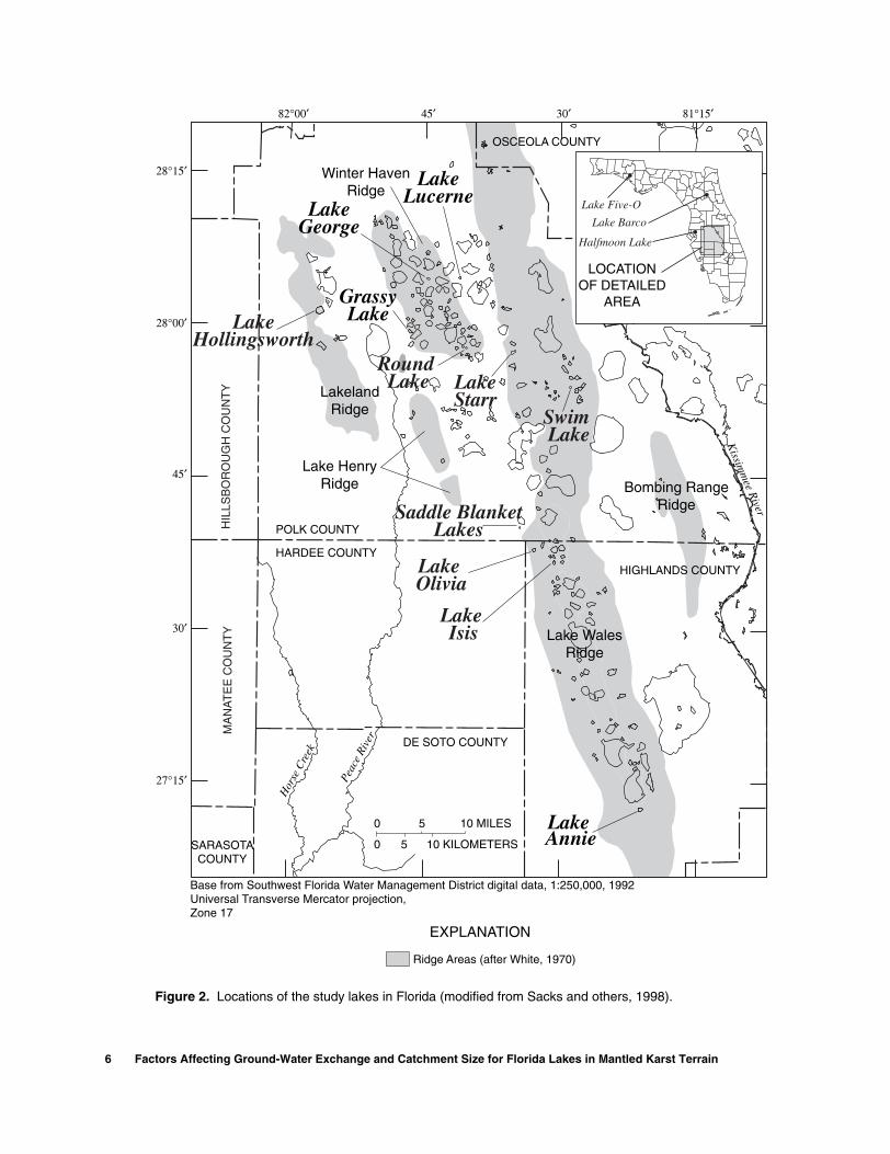
The physical settings of 14 lakes helped to define a range of basin characteristics that potentially affect ground-water interactions with lakes in Florida (fig. 2). These physical settings provided concepts for the numerical modeling of hypothetical lakes. Eleven of the lakes are located in Polk and Highlands Coun-ties (Sacks and others, 1998; Lee and others, 1991). Lake Five-O, in Bay County, is in the panhandle of Florida and its hydrogeologic setting is described in Andrews and others (1990). Lake Barco is in Putnam County in north-central Florida, and is described by Sacks and others (1992). Halfmoon Lake, in Hillsbor-ough County, is in a physiographic region called the Northern Gulf Coast Lowlands (White, 1970). The hydrogeologic setting and water budget of Halfmoon Lake are described by Metz and Sacks (2002).
The annual ground-water inflows to all 14 lakes were estimated in previous studies. Sacks and others (1998) estimated the steady-state ground-water inflow rates to 10 of the lakes using a combination of water-balance and chemical mass-balance approaches. Five of the 14 lakes (including one of the 10 lakes described above) were the subjects of detailed basin-scale model-ing studies. Ground-water inflow and lake-water leakage at Lakes Lucerne, Barco, Five-O, Starr, and Halfmoon were estimated using a combination of water-balance and numerical modeling approaches (Grubbs, 1995; Lee, 1996; Lee and Swancar, 1997; Swancar and others, 2000; Metz and Sacks, 2002; Amy Swancar and T.M. Lee, USGS, written commun., 2002; and R.Yager, USGS, Ithaca N.Y., personal commun., July 2001). The information in the following sections is taken from these sources, unless another reference is cited.
Physical Characterization of Lake Basins 5
Saint Cloud
LakeHollingsworth
GrassyLake
Round Lake Lake
StarrSwim Lake
LakeGeorge
LakeLucerne
Saddle BlanketLakes
Lake Olivia
Lake Isis
Lake Annie
Peac
e Ri
ver
Hor
se C
reek
Ridge Areas (after White, 1970)
EXPLANATION
28°15′
28°00′
45′
30′
27°15′
82°00′ 45′ 30′ 81°15′
HIGHLANDS COUNTY
OSCEOLA COUNTY
OSCEOLA COUNTY
HARDEE COUNTY
DE SOTO COUNTY
POLK COUNTYHIL
LSB
OR
OU
GH
CO
UN
TY
MA
NA
TE
E C
OU
NT
Y
SARASOTACOUNTY
Base from Southwest Florida Water Management District digital data, 1:250,000, 1992Universal Transverse Mercator projection, Zone 17
Kissim
mee R
iver
Winter HavenRidge
LakelandRidge
Lake HenryRidge
Lake WalesRidge
Bombing RangeRidge
0 5 10 MILES
0 5 10 KILOMETERS
LOCATIONOF DETAILED
AREA
Lake Five-O
Lake Barco
Halfmoon Lake
Figure 2. Locations of the study lakes in Florida (modified from Sacks and others, 1998).
6 Factors Affecting Ground-Water Exchange and Catchment Size for Florida Lakes in Mantled Karst Terrain

Methods
The physical basin characteristics compiled dur-ing the previous studies included: the size and depth of each lake, the thickness of the surficial aquifer encompassing the lake, the slope of the water table, and the thickness of the intermediate confining unit separating the surficial aquifer from the underlying Upper Floridan aquifer (table 2). In addition, the thick-ness of the unsaturated zone and the size of the topo-graphically defined basin were described for each lake.
Detailed hydrogeologic information is available for the five lakes that were the subject of basin-scale modeling studies (Lucerne, Barco, Five-O, Starr, and Halfmoon Lakes). Generalized hydrogeologic infor-mation is available for the remaining nine lake basins and was taken from regionalized lithologic maps (Buono and Rutledge, 1978; Buono and others, 1979; Tihansky and others, 1996). Information on lake bathymetry, basin topography, and geology was avail-able on all 14 of the lakes. With the exception of Swim Lake and Lake Five-O, aerial photos (scale 1 in. = 200 ft) with topographic contours at 1-ft intervals were used during this study to describe elevations along hillsides in the lake basins. Topographic maps (scale
1 in. = 24,000 in.) were used to describe the land elevation around Swim Lake and Lake Five-O.
Ground-water elevations were available in the basins of all 14 lakes. Monthly water levels measured during the previous studies of each lake were used to characterize the direction of ground-water flow in the basin, and high and low water-table conditions. Daily lake-stage data and monthly or biweekly water-table measurements typically were available. The slope of the water table was computed between adjacent moni-tor wells located along a head gradient into or out of the lake.
The potentiometric level of the Upper Flori-dan aquifer was measured in the nearest available observation well or from wells drilled onsite for the study. The head difference between the lake and the Upper Floridan aquifer was the mean of wet- and dry-season observations (typically made during May and September, respectively) (table 3). Because ground-water pumping effects are minimal in the Lake Five-O and Lake Barco basins, periodic measurements of head in the Upper Floridan aquifer generally were representative of monthly condi-tions. In contrast, periodic measurements typically made a poor surrogate for the average monthly head
Table 2. Physical characteristics of selected lake basins in Florida
[R, principal radius; r, secondary radius; ft, msl, feet above mean sea level; max, maximum; min, minimum; GW Inflow (in/yr), estimated annual ground-water inflow to lake expressed as inches per year above the lake surface area]
Lakename
Surfacearea
(acres)
Lake stage(ft msl)
Estimatedlake radius
(feet)
Basindimension
Distanceto closest
lake
Lake bedslope
(percent)
Water table1
wet seasonslope
(percent)
1Negative values indicate water table sloping away from lake.
Water tabledry season
slope(percent)
GW inflow(in/yr)
Wetseason
Dryseason
r R Min Max R Mean Max Min Max Min Max
Annie 92 110.5 109.8 500 1,000 0.2R 6.0R 4.5R 6 11 -0.1 0.5 -0.1 0.3 240
Barco 29 88.0 83.6 640 0.7R 4.0R 1.2R 3 10 -1.1 2.3 -0.7 2.2 8
Five-O 27 50.2 45.1 650 1.0R 7.0R 1.2R 7 14 0.3 1.5 0.3 1.4 237
George 59 130.5 130.0 800 0.1R 2.0R 2.0R 2 5 -0.5 1.1 -0.6 0.5 54
Grassy 76 130.9 129.7 1,000 0.8R 2.2R 1.5R 2 6 0.1 0.3 0.3 0.2 30
Halfmoon 33 42.0 40.7 300 500 0.5R 2.0R 2.0R 9 11 0.0 2.6 0.0 0.7 232
2Average of 3 years, including year with rainfall 34 inches above normal.
Hollingsworth 356 131.3 130.5 2,250 0.3R 1.3R 0.5R 0.2 0.8 0.5 1.8 0.5 1.8 110
Isis 50 108.7 109.5 600 650 0.5R 7.0R 2.5R 9 14 -0.6 1.8 -1.2 1.4 100
Lucerne 38 126.0 124.8 860 1.0R 2.0R 0.8R 2 5 0.5 0.6 0.1 0.3 24
Olivia 86 114.5 114.7 800 0.3R 3.5R 1.0R 5 13 -0.4 0.7 -0.4 0.6 33
Round 31 131.4 130.8 650 0.7R 1.7R 1.2R 4 11 0.4 1.0 0.1 0.3 6
Saddle Blanket 6 116.9 117.7 330 1.0R 7.0R 1.0R 3 7 -0.2 0.7 -0.6 0.4 30
Starr 134 103.9 104.2 650 1,000 1.0R 2.0R 2.2R 3 9 -0.2 0.2 -0.2 0.2 23
Swim 5 96.8 96.2 240 1.0R 3.0R 2.0R 12 20 -0.1 0.8 -0.1 0.9 180
mean 1.1 0.8
median 0.9 0.6
Physical Characterization of Lake Basins 7
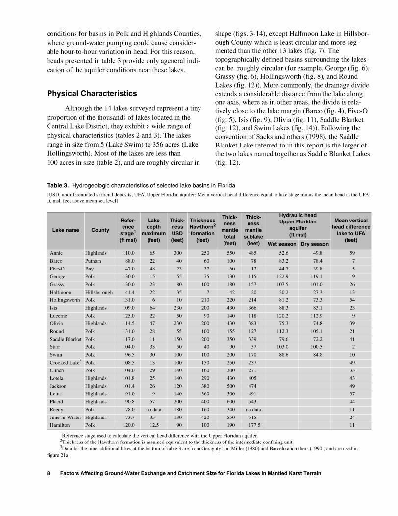
conditions for basins in Polk and Highlands Counties, where ground-water pumping could cause consider-able hour-to-hour variation in head. For this reason, heads presented in table 3 provide only ageneral indi-cation of the aquifer conditions near these lakes.
Physical Characteristics
Although the 14 lakes surveyed represent a tiny proportion of the thousands of lakes located in the Central Lake District, they exhibit a wide range of physical characteristics (tables 2 and 3). The lakes range in size from 5 (Lake Swim) to 356 acres (Lake Hollingsworth). Most of the lakes are less than 100 acres in size (table 2), and are roughly circular in
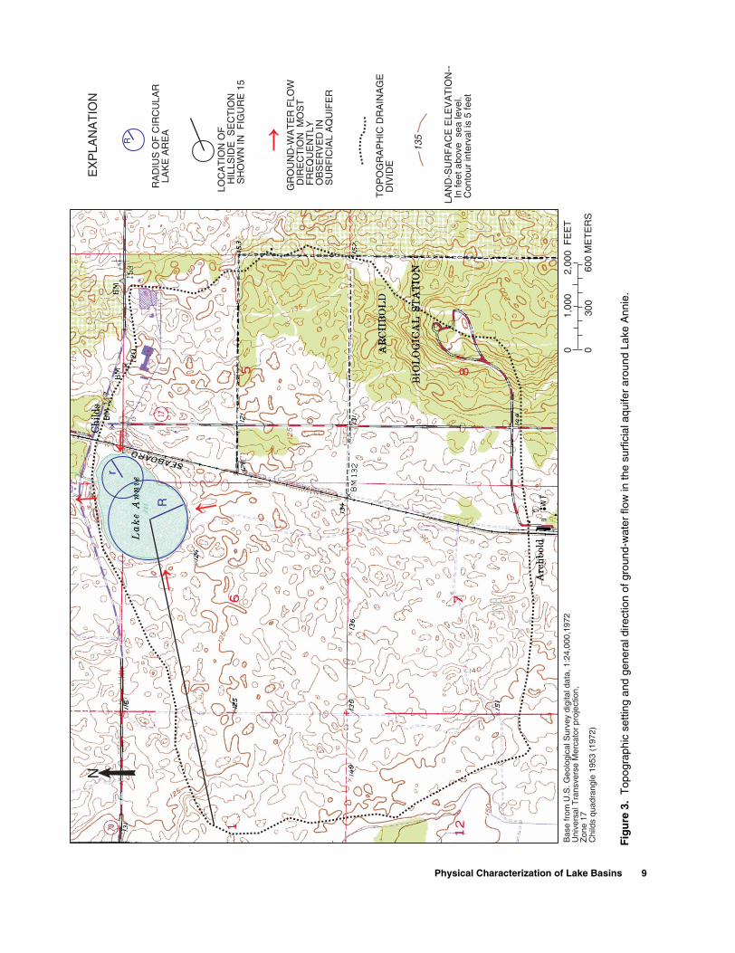
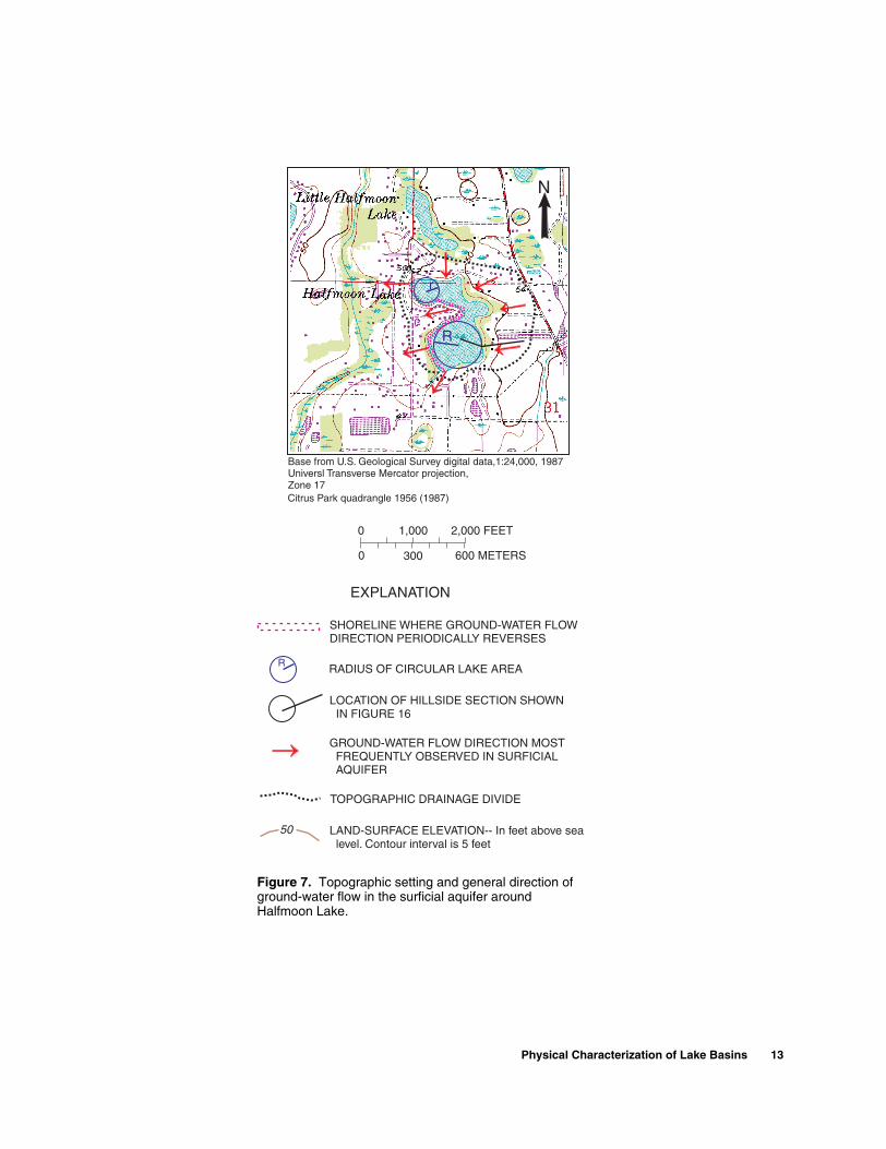
shape (figs. 3-14), except Halfmoon Lake in Hillsbor-ough County which is least circular and more seg-mented than the other 13 lakes (fig. 7). The topographically defined basins surrounding the lakes can be roughly circular (for example, George (fig. 6), Grassy (fig. 6), Hollingsworth (fig. 8), and Round Lakes (fig. 12)). More commonly, the drainage divide extends a considerable distance from the lake along one axis, where as in other areas, the divide is rela-tively close to the lake margin (Barco (fig. 4), Five-O (fig. 5), Isis (fig. 9), Olivia (fig. 11), Saddle Blanket (fig. 12), and Swim Lakes (fig. 14)). Following the convention of Sacks and others (1998), the Saddle Blanket Lake referred to in this report is the larger of the two lakes named together as Saddle Blanket Lakes (fig. 12).
Table 3. Hydrogeologic characteristics of selected lake basins in Florida
[USD, undifferentiated surficial deposits; UFA, Upper Floridan aquifer; Mean vertical head difference equal to lake stage minus the mean head in the UFA; ft, msl, feet above mean sea level]
Lake name County
Refer-ence
stage1
(ft msl)
1Reference stage used to calculate the vertical head difference with the Upper Floridan aquifer.
Lakedepth
maximum(feet)
Thick-nessUSD(feet)
ThicknessHawthorn2
formation(feet)
2Thickness of the Hawthorn formation is assumed equivalent to the thickness of the intermediate confining unit.
Thick-ness
mantletotal(feet)
Thick-ness
mantlesublake
(feet)
Hydraulic headUpper Floridan
aquifer (ft msl)
Mean verticalhead difference
lake to UFA(feet)
Wet season Dry season
Annie Highlands 110.0 65 300 250 550 485 52.6 49.8 59
Barco Putnam 88.0 22 40 60 100 78 83.2 78.4 7
Five-O Bay 47.0 48 23 37 60 12 44.7 39.8 5
George Polk 130.0 15 55 75 130 115 122.9 119.1 9
Grassy Polk 130.0 23 80 100 180 157 107.5 101.0 26
Halfmoon Hillsborough 41.4 22 35 7 42 20 30.2 27.3 13
Hollingsworth Polk 131.0 6 10 210 220 214 81.2 73.3 54
Isis Highlands 109.0 64 230 200 430 366 88.3 83.1 23
Lucerne Polk 125.0 22 50 90 140 118 120.2 112.9 9
Olivia Highlands 114.5 47 230 200 430 383 75.3 74.8 39
Round Polk 131.0 28 55 100 155 127 112.3 105.1 21
Saddle Blanket Polk 117.0 11 150 200 350 339 79.6 72.2 41
Starr Polk 104.0 33 50 40 90 57 103.0 100.5 2
Swim Polk 96.5 30 100 100 200 170 88.6 84.8 10
Crooked Lake3
3Data for the nine additional lakes at the bottom of table 3 are from Geraghty and Miller (1980) and Barcelo and others (1990), and are used in figure 21a.
Polk 108.5 13 100 150 250 237 49
Clinch Polk 104.0 29 140 160 300 271 33
Lotela Highlands 101.8 25 140 290 430 405 43
Jackson Highlands 101.4 26 120 380 500 474 49
Letta Highlands 91.0 9 140 360 500 491 37
Placid Highlands 90.8 57 200 400 600 543 44
Reedy Polk 78.0 no data 180 160 340 no data 11
June-in-Winter Highlands 73.7 35 130 420 550 515 24
Hamilton Polk 120.0 12.5 90 100 190 177.5 11
8 Factors Affecting Ground-Water Exchange and Catchment Size for Florida Lakes in Mantled Karst Terrain
RA
DIU
S O
F C
IRC
ULA
R
LA
KE
AR
EA
LOC
AT
ION
OF
H
ILLS
IDE
SE
CT
ION
S
HO
WN
IN F
IGU
RE
15
TO
PO
GR
AP
HIC
DR
AIN
AG
E D
IVID
E
LAN
D-S
UR
FA
CE
ELE
VA
TIO
N--
I
n fe
et a
bove
sea
leve
l. C
onto
ur in
terv
al is
5 fe
et
GR
OU
ND
-WA
TE
R F
LOW
D
IRE
CT
ION
MO
ST
F
RE
QU
EN
TLY
O
BS
ER
VE
D IN
S
UR
FIC
IAL
AQ
UIF
ER
R
EX
PLA
NA
TIO
N
135
Bas
e fr
om U
.S. G
eolo
gica
l Sur
vey
digi
tal d
ata,
1:2
4,00
0,19
72U
nive
rsal
Tra
nsve
rse
Mer
cato
r pr
ojec
tion,
Zon
e 17
Chi
lds
quad
rang
le 1
953
(197
2)
0 030
0
1,00
02,
000
FE
ET
600
ME
TE
RS
R
r
N
Fig
ure
3.
Top
ogra
phic
set
ting
and
gene
ral d
irect
ion
of g
roun
d-w
ater
flow
in th
e su
rfic
ial a
quife
r ar
ound
Lak
e A
nnie
.
Physical Characterization of Lake Basins 9

0
0 300
1,000 2,000 FEET
600 METERS
Melrose quadrangle 1966 (1981)
SHORELINE WHERE GROUND-WATER FLOWDIRECTION PERIODICALLY REVERSES
RADIUS OF CIRCULAR LAKE AREA
LOCATION OF HILLSIDE SECTION SHOWNIN FIGURE 15
TOPOGRAPHIC DRAINAGE DIVIDE
LAND-SURFACE CONTOUR- Elevation in feetabove sea level. Contour interval is 5 feet
SIMULATED GROUND-WATER CATCHMENT
GROUND-WATER FLOW DIRECTION MOSTFREQUENTLY OBSERVED IN SURFICIALAQUIFER
R
N
EXPLANATION
R
Base from U.S. Geological Survey digital data, 1:24,000,1981Universal Transverse Mercator projection,Zone 17
Lake Barco
DIRECTION OFGROUND-WATER FLOW
100
Figure 4. Topographic setting of Lake Barco, general direction of ground-water flow in the surrounding surficial aquifer, and the simulated steady-state ground-water catchment (modified from Lee, 1996).
10 Factors Affecting Ground-Water Exchange and Catchment Size for Florida Lakes in Mantled Karst Terrain

RA
DIU
S O
F C
IRC
ULA
R L
AK
E A
RE
A
LOC
ATIO
N O
F H
ILLS
IDE
SE
CT
ION
SH
OW
N IN
FIG
UR
E 1
6
TOP
OG
RA
PH
IC D
RA
INA
GE
DIV
IDE
LAN
D-S
UR
FAC
E E
LEV
ATIO
N--
In m
eter
s ab
ove
sea
leve
l.C
onto
ur in
terv
al is
two
met
ers
SIM
ULA
TE
D G
RO
UN
D-W
ATE
R C
ATC
HM
EN
T
GR
OU
ND
-WAT
ER
FLO
W D
IRE
CT
ION
MO
ST
FR
EQ
UE
NT
LYO
BS
ER
VE
D IN
SU
RF
ICIA
L A
QU
IFE
R
R
EX
PLA
NAT
ION
R
N
Lak
eF
ive-
O
Lake
Fiv
e-O
0 030
0
1,00
02,
000
FE
ET
600
ME
TE
RS
26
Cry
stal
Lak
e qu
adra
ngle
198
2
Bas
e fr
om U
.S.G
eolo
gica
l Sur
vey
digi
tal d
ata,
1:2
4,00
0, 1
987
Uni
vers
alTr
ansv
erse
Mer
cato
r pr
ojec
tion,
Zon
e 17
DIR
EC
TIO
N O
FG
RO
UN
D-W
AT
ER
FLO
W
Fig
ure
5.
Top
ogra
phic
set
ting
of L
ake
Fiv
e-O
, gen
eral
dire
ctio
n of
gro
und-
wat
er fl
ow in
the
surr
ound
ing
surf
icia
l aqu
ifer,
and
the
sim
ulat
ed s
tead
y-st
ate
grou
nd-w
ater
cat
chm
ent (
mod
ified
from
Gru
bbs,
199
5).
Not
e th
e si
mul
ated
gro
und-
wat
er c
atch
men
t ext
ends
be
yond
the
topo
grap
hic
drai
nage
div
ide
east
of t
he la
ke.
Physical Characterization of Lake Basins 11

R
134
133
R
SHORELINE WHERE GROUND-WATER FLOWDIRECTION PERIODICALLY REVERSES
RADIUS OF CIRCULAR LAKE AREA
LOCATION OF HILLSIDE SECTIONSHOWN IN FIGURE 16
TOPOGRAPHIC DRAINAGE DIVIDE
LAND-SURFACE ELEVATION--In feet above sealevel. Contour interval is 5 feet at Lake Georgeand 10 feet at Grassy Lake
R
EXPLANATION
N
N
GROUND-WATER FLOW DIRECTION MOSTFREQUENTLY OBSERVED IN SURFICIALAQUIFER
Base from U.S. Geological Survey digital data, 1:24,000, 1980, 1988TUniversal ransverse Mercator projection,
Zone 17
130
.Base from U.S Geological Survey digital data, 1:24,000, 1987Universal Transverse Mercator projection,Zone 17
Winter Haven quadrangle 1959 (1980)
Bartow quadrangle 1949 (1987)
0
0 300
1,000 2,000 FEET
600 METERS
Figure 6. Topographic setting and general direction of ground-water flow in the surficial aquifer around Lake George and Grassy Lake.
12 Factors Affecting Ground-Water Exchange and Catchment Size for Florida Lakes in Mantled Karst Terrain
SHORELINE WHERE GROUND-WATER FLOWDIRECTION PERIODICALLY REVERSES
RADIUS OF CIRCULAR LAKE AREA
LOCATION OF HILLSIDE SECTION SHOWNIN FIGURE 16
TOPOGRAPHIC DRAINAGE DIVIDE
LAND-SURFACE ELEVATION-- In feet above sealevel. Contour interval is 5 feet
GROUND-WATER FLOW DIRECTION MOSTFREQUENTLY OBSERVED IN SURFICIALAQUIFER
R
EXPLANATION
R
r
N
Base from U.S. Geological Survey digital data,1:24,000, 1987Universl Transverse Mercator projection,Zone 17
50
Citrus Park quadrangle 1956 (1987)
0 1,000 2,000 FEET
0 600 METERS300
Figure 7. Topographic setting and general direction of ground-water flow in the surficial aquifer around Halfmoon Lake.
Physical Characterization of Lake Basins 13

Lakeland quadrangle 1975 (1987)
R
N
RADIUS OF CIRCULAR LAKE AREA
LOCATION OF HILLSIDE SECTION SHOWN IN FIGURE 17
TOPOGRAPHIC DRAINAGE DIVIDE
LAND-SURFACE ELEVATION-- In feet above sea level.Contour interval is 5 feet
GROUND-WATER FLOW DIRECTION MOST FREQUENTLY OBSERVEDIN SURFICIAL AQUIFER
R
EXPLANATION
Base from U.S. Geological Survey digital data, 1:24,000, 1987Universal Transverse Mercator projection,Zone 17
200
0
0 300
1,000 2,000 FEET
600 METERS
Figure 8. Topographic setting and general direction of ground-water flow in the surficial aquifer around Lake Hollingsworth.
14 Factors Affecting Ground-Water Exchange and Catchment Size for Florida Lakes in Mantled Karst Terrain
R
r
Lake Byrd108
Lake Brentwood104
N
RADIUS OF CIRCULAR LAKE AREA
TOPOGRAPHIC DRAINAGE DIVIDE
LAND-SURFACE ELEVATION-- In feet above sea level.Contour interval is 5 feet
GROUND-WATER FLOW DIRECTION MOST FREQUENTLY OBSERVED IN SURFICIAL AQUIFER
R
EXPLANATION
Avon Park quadrangle 1953 (1987)
Base from U.S. Geological Survey digital data, 1:24,000, 1987Universal Transverse Mercator projection,Zone 17
0
0 300
1,000 2,000 FEET
600 METERS
150
LOCATION OF HILLSIDE SECTION SHOWN IN FIGURE 17
Figure 9. Topographic setting and general direction of ground-water flow in the surficial aquifer around Lake Isis.
Physical Characterization of Lake Basins 15

R
Winter Haven quadrangle 1959 (1980)
N
RADIUS OF CIRCULAR LAKE AREA
LOCATION OF HILLSIDE SECTION SHOWN IN FIGURE 18
TOPOGRAPHIC DRAINAGE DIVIDE
LAND-SURFACE ELEVATION-- In feet above sea level.Contour interval is 5 feet
GROUND-WATER FLOW DIRECTION MOST FREQUENTLY OBSERVEDIN SURFICIAL AQUIFER
R
EXPLANATION
Base from U.S. Geological Survey digital data, 1:24,000, 1980Universal Transverse Mercator projection,Zone 17
150
0
0 300
1,000 2,000 FEET
600 METERS
Figure 10. Topographic setting and general direction of ground-water flow in the surficial aquifer around Lake Lucerne.
16 Factors Affecting Ground-Water Exchange and Catchment Size for Florida Lakes in Mantled Karst Terrain
Avon P ark quadrangle 1953 (1987)Frostproof quadrangle 1953 (1972)
R
N
SHORELINE WHERE GROUND-WATER FLOWDIRECTION PERIODICALLY REVERSES
RADIUS OF CIRCULAR LAKE AREA
LOCATION OF HILLSIDE SECTION SHOWN IN FIGURE 18
TOPOGRAPHIC DRAINAGE DIVIDE
LAND-SURFACE ELEVATION-- In feet above sea level.Contour interval is 5 feet
GROUND-WATER FLOW DIRECTION MOST FREQUENTLYOBSERVED IN SURFICIAL AQUIFER
R
EXPLANATION
Base from U.S. Geological Survey digital data, 1:24,000, 1972, 1987Universal Transverse Mercator projection,Zone 17
100
0
0 300
1,000 2,000 FEET
600 METERS
Figure 11. Topographic setting and general direction of ground-water flow in the surficial aquifer around Lake Olivia.
Physical Characterization of Lake Basins 17

R
105Lake Streety
Frostproof quadrangle 1953 (1972)
LakeWinterset
131
125
Eloise quadrangle 1955 (1987)
N
N
SHORELINE WHERE GROUND-WATER FLOWDIRECTION PERIODICALLY REVERSES
RADIUS OF CIRCULAR LAKE AREA
LOCATION OF HILLSIDE SECTIONSHOWN IN FIGURE 19
TOPOGRAPHIC DRAINAGE DIVIDE
LAND-SURFACE ELEVATION-- In feet above sea level.Contour interval is 10 feet at Round Lake and 5 feetat Saddle Blanket Lake
GROUND-WATER FLOW DIRECTION MOSTFREQUENTLY OBSERVED IN SURFICIAL AQUIFER
R
EXPLANATION
R
125
Base from U.S. Geological Survey digital data, 1:24,000, 1987Universal Transverse Mercator projection,Zone 17
Base from U.S. Geological Survey digital data, 1:24,000, 1972Universal Transverse Mercator projection,Zone 17
0
0 300
1,000 2,000 FEET
600 METERS
Figure 12. Topographic setting and general direction of ground-water flow in the surficial aquifer around Round Lake and Saddle Blanket Lakes.
18 Factors Affecting Ground-Water Exchange and Catchment Size for Florida Lakes in Mantled Karst Terrain
Lake
Wal
es q
uadr
angl
e 19
87
N
RA
DIU
S O
F C
IRC
ULA
R L
AK
E A
RE
A
LOC
ATIO
N O
F H
ILLS
IDE
SE
CT
ION
SH
OW
N IN
FIG
UR
E 2
0
TOP
OG
RA
PH
IC D
RA
INA
GE
DIV
IDE
LAN
D-S
UR
FAC
E E
LEV
ATIO
N--
In fe
et a
bove
sea
leve
l.C
onto
ur in
terv
al is
5 fe
et
SIM
ULA
TE
D G
RO
UN
D-W
ATE
R C
ATC
HM
EN
T
GR
OU
ND
-WAT
ER
FLO
W D
IRE
CT
ION
MO
ST
FR
EQ
UE
NT
LY O
BS
ER
VE
D IN
SU
RF
ICIA
L A
QU
IFE
R
R
EX
PLA
NAT
ION
Lake
Sta
rr
R
r
200
Bas
e fr
om U
.S.G
eolo
gica
l Sur
vey
digi
tal d
ata,
1:2
4,00
0, 1
987
Uni
vers
alTr
ansv
erse
Mer
cato
r pr
ojec
tion,
Zon
e 17
0 030
0
1,00
02,
000
FE
ET
600
ME
TE
RS
DIR
EC
TIO
N O
FG
RO
UN
D-W
AT
ER
FLO
W
Fig
ure
13.
Top
ogra
phic
set
ting
of L
ake
Sta
rr, g
ener
al d
irect
ion
of g
roun
d-w
ater
flow
in th
e su
rrou
ndin
g su
rfic
ial a
quife
r, a
nd th
e si
mul
ated
ste
ady-
stat
e gr
ound
-wat
er c
atch
men
t.
Physical Characterization of Lake Basins 19
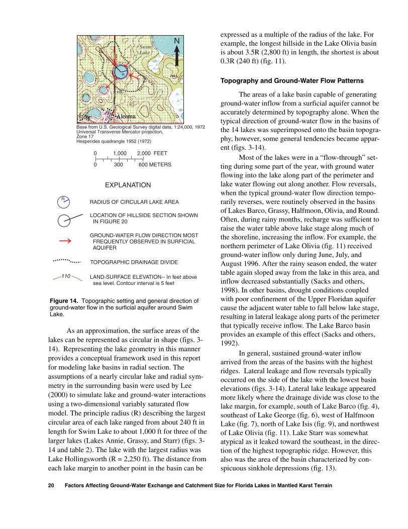
As an approximation, the surface areas of the lakes can be represented as circular in shape (figs. 3-14). Representing the lake geometry in this manner provides a conceptual framework used in this report for modeling lake basins in radial section. The assumptions of a nearly circular lake and radial sym-metry in the surrounding basin were used by Lee (2000) to simulate lake and ground-water interactions using a two-dimensional variably saturated flow model. The principle radius (R) describing the largest circular area of each lake ranged from about 240 ft in length for Swim Lake to about 1,000 ft for three of the larger lakes (Lakes Annie, Grassy, and Starr) (figs. 3-14 and table 2). The lake with the largest radius was Lake Hollingsworth (R = 2,250 ft). The distance from each lake margin to another point in the basin can be
expressed as a multiple of the radius of the lake. For example, the longest hillside in the Lake Olivia basin is about 3.5R (2,800 ft) in length, the shortest is about 0.3R (240 ft) (fig. 11).
Topography and Ground-Water Flow Patterns
The areas of a lake basin capable of generating ground-water inflow from a surficial aquifer cannot be accurately determined by topography alone. When the typical direction of ground-water flow in the basins of the 14 lakes was superimposed onto the basin topogra-phy, however, some general tendencies became appar-ent (figs. 3-14).
Most of the lakes were in a “flow-through” set-ting during some part of the year, with ground water flowing into the lake along part of the perimeter and lake water flowing out along another. Flow reversals, when the typical ground-water flow direction tempo-rarily reverses, were routinely observed in the basins of Lakes Barco, Grassy, Halfmoon, Olivia, and Round. Often, during rainy months, recharge was sufficient to raise the water table above lake stage along much of the shoreline, increasing the inflow. For example, the northern perimeter of Lake Olivia (fig. 11) received ground-water inflow only during June, July, and August 1996. After the rainy season ended, the water table again sloped away from the lake in this area, and inflow decreased substantially (Sacks and others, 1998). In other basins, drought conditions coupled with poor confinement of the Upper Floridan aquifer cause the adjacent water table to fall below lake stage, resulting in lateral leakage along parts of the perimeter that typically receive inflow. The Lake Barco basin provides an example of this effect (Sacks and others, 1992).
In general, sustained ground-water inflow arrived from the areas of the basins with the highest ridges. Lateral leakage and flow reversals typically occurred on the side of the lake with the lowest basin elevations (figs. 3-14). Lateral lake leakage appeared more likely where the drainage divide was close to the lake margin, for example, south of Lake Barco (fig. 4), southeast of Lake George (fig. 6), west of Halfmoon Lake (fig. 7), north of Lake Isis (fig. 9), and northwest of Lake Olivia (fig. 11). Lake Starr was somewhat atypical as it leaked toward the southeast, in the direc-tion of the highest topographic ridge. However, this also was the area of the basin characterized by con-spicuous sinkhole depressions (fig. 13).
SwimLake
R
N
RADIUS OF CIRCULAR LAKE AREA
LOCATION OF HILLSIDE SECTION SHOWNIN FIGURE 20
TOPOGRAPHIC DRAINAGE DIVIDE
LAND-SURFACE ELEVATION-- In feet abovesea level. Contour interval is 5 feet
GROUND-WATER FLOW DIRECTION MOSTFREQUENTLY OBSERVED IN SURFICIALAQUIFER
R
EXPLANATION
Hesperides quadrangle 1952 (1972)
Base from U.S. Geological Survey digital data, 1:24,000, 1972Universal Transverse Mercator projection,Zone 17
110
0
0 300
1,000 2,000 FEET
600 METERS
Figure 14. Topographic setting and general direction of ground-water flow in the surficial aquifer around Swim Lake.
20 Factors Affecting Ground-Water Exchange and Catchment Size for Florida Lakes in Mantled Karst Terrain

Proximity to other lakes also may affect the pat-tern of ground-water flow around the 14 lakes. Thirteen of the 14 lakes were within 2.5R of one or more lakes, and 8 were within 1.5R (table 2). Lake Annie was far-thest from any lake (about 4.5R). The tendency for ground water from the intervening basin to enter the lake is affected by whether the adjacent lake is higher or lower. For example, lake water typically leaked out lat-erally through the eastern shoreline of Round Lake toward a region of the eastern basin with low topogra-phy and a short hillside (fig. 12). Although the basin topography is similar on the western side of the lake, the lake consistently received ground-water inflow in this area. This may be because nearby Lake Winterset, which had a slightly higher stage than Round Lake, kept the adjacent water table elevated (fig. 12).
Ground-water catchments were simulated in previous studies for Lakes Barco, Five-O, and Starr using three-dimensional, finite-difference, saturated ground-water flow modeling combined with particle tracking. The models resolved steady-state flow-field velocities to determine the pathlines of ground water entering the lake. The extent of these pathlines defined the catchment. All of the ground water within the simulated ground-water catchment eventually flows into the lake. The sizes of the ground-water catchments for Lakes Barco, Five-O, and Starr differed substantially. The ground-water catchments to Lakes Barco and Starr reached about 0.3R and 1.0R from their respective lake margins, but both catchments were much smaller than their topographically defined basins (figs. 4 and 13). In contrast, at Lake Five-O, the ground-water catchment encompassed most of the topographic basin (fig. 5).
Hydrogeologic Framework
The size of ground-water catchments depends upon the hydrogeologic framework of the lake basin as well as basin topography. Hillside views of the basins reveal differences and similarities in the physical and geologic settings of the 14 lakes (see figs. 15-20). Hillside views are the perspective used in the two-dimensional modeling in the next section. The location of each hillside is shown on basin maps (figs. 3-14). Hillsides begin in the lake center at the lowest land-surface elevation (lake bottom), and end at the hilltop of the topographic drainage divide. Hillside views plotted at the same horizontal and vertical scale show the depth and slope of the lakebeds, basin radius and elevation, the thickness of the surficial aquifer and the
intermediate confining unit, as well as the thickness of the unsaturated zone (figs. 15-20). The bottom eleva-tion of each cross section is the approximate top of the Upper Floridan aquifer in the basin.
The thickness of the surficial deposits within the basins ranged widely from about 10 ft at Lake Holling-sworth to about 300 ft at Lake Annie (table 3). Although the hydraulic conductivity of the surficial aquifer was not known for all of the 14 basins, in the 5 intensively studied basins, the surficial aquifer con-ductivity ranged over an order of magnitude. The rep-resentative horizontal hydraulic conductivity (Kh) in the shallow surficial aquifer was about 60 feet per day (ft/d) at Five-O, 30 ft/day at Lake Starr, 8 ft/d at Lake Lucerne, 5 ft/d at Halfmoon Lake, and 3 ft/day at Lake Barco. Anisotropy was not directly determined in any of the basins, but the surficial deposits were heteroge-neous and Kh typically decreased with depth in the surficial aquifer.
The depth of the water table below land surface also varied considerably among basins. Along the southern extent of the Lake Starr basin, the water table was overlain by nearly 120 ft of unsaturated material (fig. 20). At Lake Annie, the maximum unsaturated thickness was about 10 ft (fig. 15). Unsaturated zone thickness was affected more by topography than by the slope of the water table, which by comparison was rel-atively flat. At the end of a wet season, the maximum water-table slope found on the inflow side of the lakes ranged from 0.2 to 2.6 percent (2.6 ft vertical change per 100 ft horizontal distance). The maximum slope measured was less than 1 percent at Lakes Annie, Grassy, Lucerne, Olivia, Saddle Blanket, Starr, and Swim. The maximum water-table slope was greater than 1 percent at Lakes Barco, Five-O, George, Half-moon, Hollingsworth and Isis. Lakes Barco and Isis, which were flow-through lakes, also had the largest negative water-table slopes on their outflow sides (table 2).
The lakes ranged in depth from 6 ft (Holling-sworth) to 65 ft (Annie) (figs. 15 and 17, and table 3). Four of the 14 lakes were considered deep, with a maximum depth greater than 45 ft (Annie, Five-O, Isis, and Olivia). The beds of these lakes also had steep slopes (maximum bed slope greater than 10 per-cent). Swim Lake, with a maximum depth of 30 ft but a small surface area (5 acres) had the steepest bed slope (maximum about 20 percent). Of the five lakes estimated to receive the highest ground-water inflow, four also had a steep bed slope (Annie, Five-O, Isis,
Physical Characterization of Lake Basins 21
EDSITS
ge divide
4,000
UIFER
FEET
the ations are
Lake Annie
INTERMEDIATECONFININGUNIT
UNDIFFERENTIATSURFICIAL DEPO
440
400
360
320
280
240
200
160
120
80
40
40
80
120
160
SEA LEVEL Lake center
Topographic draina
0 1,000 2,000 3,000
Lake Barco
10
20
60
100
140
180
SEA LEVEL
EXPLANATION
WATER TABLE
LAND SURFACE
LAKE SURFACE
ELE
VA
TIO
N A
BO
VE
OR
BE
LOW
SE
A L
EV
EL,
IN F
EE
T
TOP OF UPPER FLORIDAN AQ
DISTANCE FROM LAKE CENTER, IN
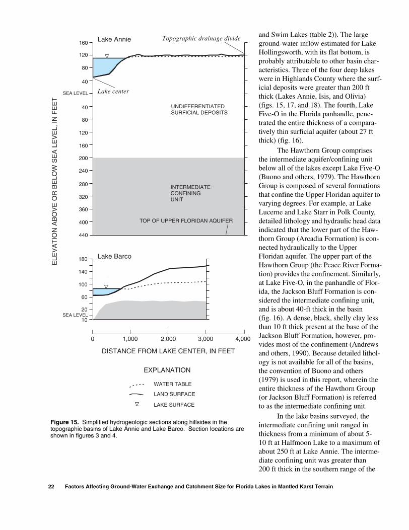
Figure 15. Simplified hydrogeologic sections along hillsides intopographic basins of Lake Annie and Lake Barco. Section locshown in figures 3 and 4.
22 Factors Affecting Ground-Water Exchange and Catchment Size for Florida
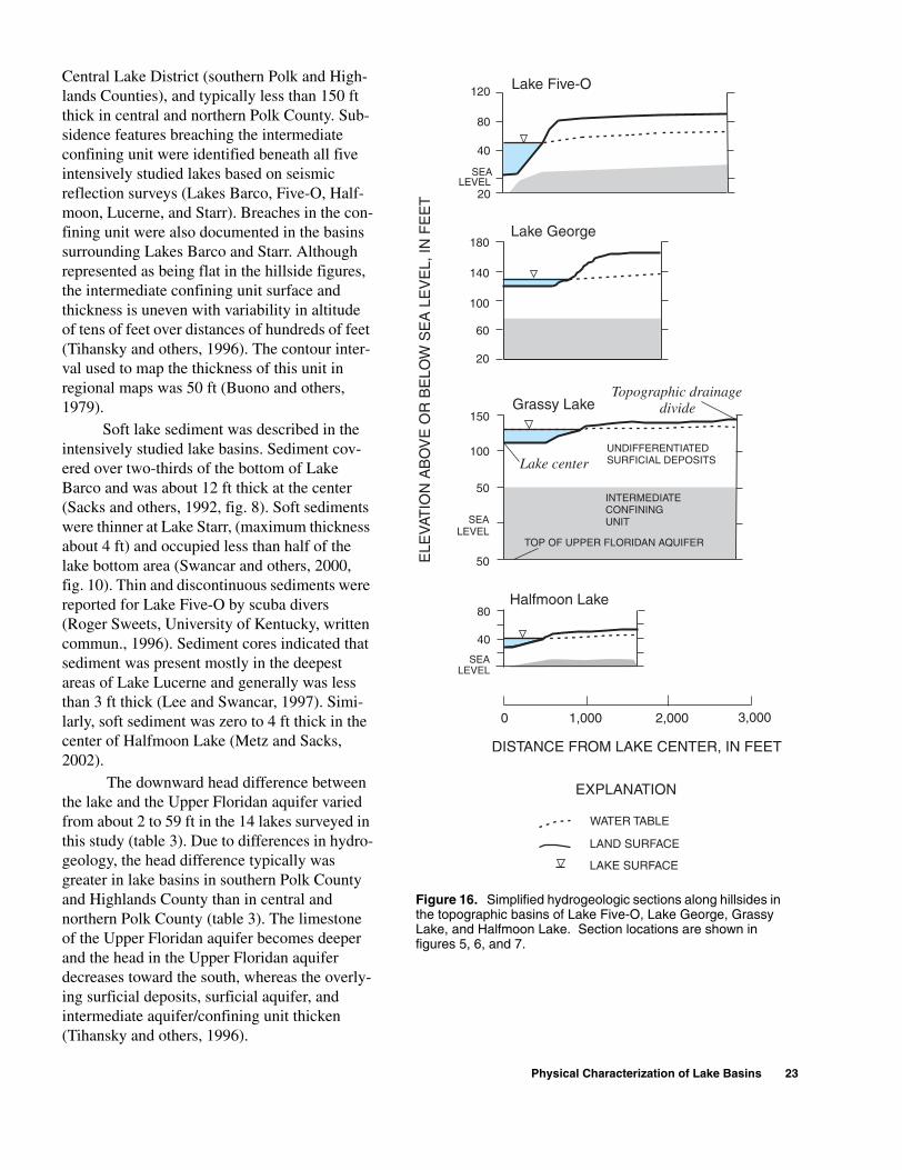
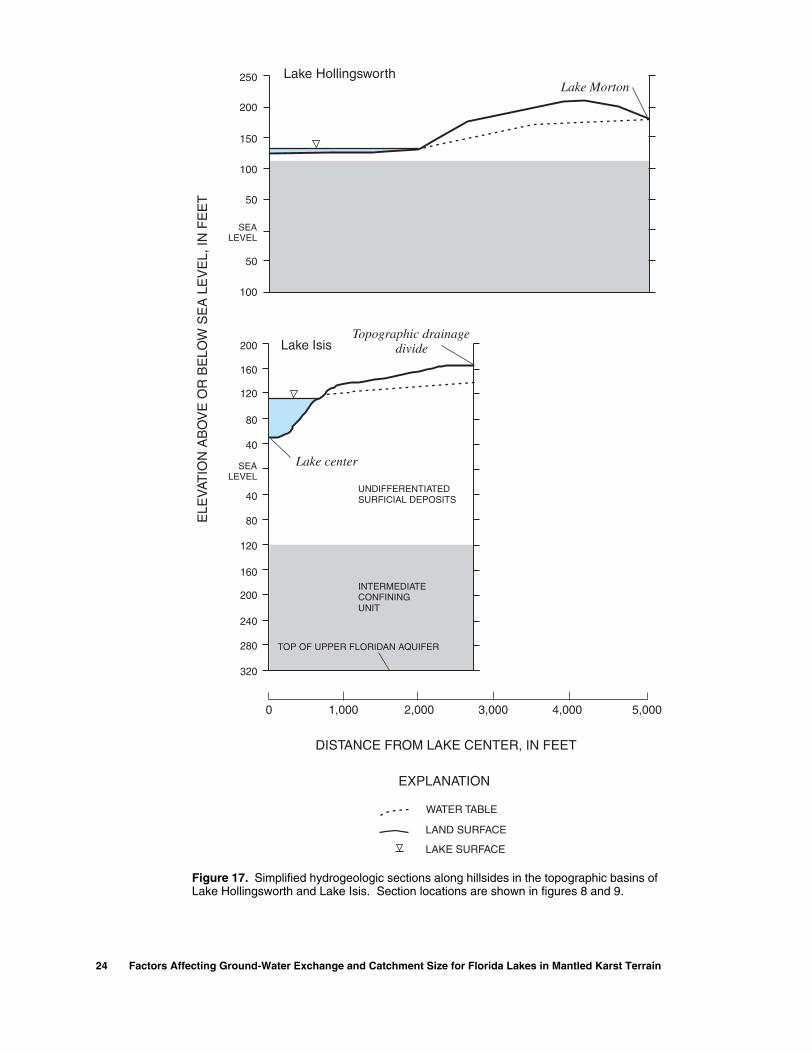
and Swim Lakes (table 2)). The large ground-water inflow estimated for Lake Hollingsworth, with its flat bottom, is probably attributable to other basin char-acteristics. Three of the four deep lakes were in Highlands County where the surf-icial deposits were greater than 200 ft thick (Lakes Annie, Isis, and Olivia) (figs. 15, 17, and 18). The fourth, Lake Five-O in the Florida panhandle, pene-trated the entire thickness of a compara-tively thin surficial aquifer (about 27 ft thick) (fig. 16).
The Hawthorn Group comprises the intermediate aquifer/confining unit below all of the lakes except Lake Five-O (Buono and others, 1979). The Hawthorn Group is composed of several formations that confine the Upper Floridan aquifer to varying degrees. For example, at Lake Lucerne and Lake Starr in Polk County, detailed lithology and hydraulic head data indicated that the lower part of the Haw-thorn Group (Arcadia Formation) is con-nected hydraulically to the Upper Floridan aquifer. The upper part of the Hawthorn Group (the Peace River Forma-tion) provides the confinement. Similarly, at Lake Five-O, in the panhandle of Flor-ida, the Jackson Bluff Formation is con-sidered the intermediate confining unit, and is about 40-ft thick in the basin (fig. 16). A dense, black, shelly clay less than 10 ft thick present at the base of the Jackson Bluff Formation, however, pro-vides most of the confinement (Andrews and others, 1990). Because detailed lithol-ogy is not available for all of the basins, the convention of Buono and others (1979) is used in this report, wherein the entire thickness of the Hawthorn Group (or Jackson Bluff Formation) is referred to as the intermediate confining unit.
In the lake basins surveyed, the intermediate confining unit ranged in thickness from a minimum of about 5-10 ft at Halfmoon Lake to a maximum of about 250 ft at Lake Annie. The interme-diate confining unit was greater than 200 ft thick in the southern range of the
Lakes in Mantled Karst Terrain
Central Lake District (southern Polk and High-lands Counties), and typically less than 150 ft thick in central and northern Polk County. Sub-sidence features breaching the intermediate confining unit were identified beneath all five intensively studied lakes based on seismic reflection surveys (Lakes Barco, Five-O, Half-moon, Lucerne, and Starr). Breaches in the con-fining unit were also documented in the basins surrounding Lakes Barco and Starr. Although represented as being flat in the hillside figures, the intermediate confining unit surface and thickness is uneven with variability in altitude of tens of feet over distances of hundreds of feet (Tihansky and others, 1996). The contour inter-val used to map the thickness of this unit in regional maps was 50 ft (Buono and others, 1979).
Soft lake sediment was described in the intensively studied lake basins. Sediment cov-ered over two-thirds of the bottom of Lake Barco and was about 12 ft thick at the center (Sacks and others, 1992, fig. 8). Soft sediments were thinner at Lake Starr, (maximum thickness about 4 ft) and occupied less than half of the lake bottom area (Swancar and others, 2000, fig. 10). Thin and discontinuous sediments were reported for Lake Five-O by scuba divers (Roger Sweets, University of Kentucky, written commun., 1996). Sediment cores indicated that sediment was present mostly in the deepest areas of Lake Lucerne and generally was less than 3 ft thick (Lee and Swancar, 1997). Simi-larly, soft sediment was zero to 4 ft thick in the center of Halfmoon Lake (Metz and Sacks, 2002).
The downward head difference between the lake and the Upper Floridan aquifer varied from about 2 to 59 ft in the 14 lakes surveyed in this study (table 3). Due to differences in hydro-geology, the head difference typically was greater in lake basins in southern Polk County and Highlands County than in central and northern Polk County (table 3). The limestone of the Upper Floridan aquifer becomes deeper and the head in the Upper Floridan aquifer decreases toward the south, whereas the overly-ing surficial deposits, surficial aquifer, and intermediate aquifer/confining unit thicken (Tihansky and others, 1996).
DISTANCE FROM LAKE CENTER, IN FEET
ELE
VAT
ION
AB
OV
E O
R B
ELO
W S
EA
LE
VE
L, IN
FE
ET
0 1,000 2,000 3,000
INTERMEDIATECONFININGUNIT
UNDIFFERENTIATEDSURFICIAL DEPOSITS
Grassy Lake150
100
50
SEALEVEL
50
Lake center
TOP OF UPPER FLORIDAN AQUIFER
WATER TABLE
LAND SURFACE
LAKE SURFACE
EXPLANATION
Lake Five-O
40
20
80
120
SEALEVEL
180
140
100
60
20
Lake George
Halfmoon Lake80
40
SEA LEVEL
Topographic drainage divide
Figure 16. Simplified hydrogeologic sections along hillsides in the topographic basins of Lake Five-O, Lake George, Grassy Lake, and Halfmoon Lake. Section locations are shown in figures 5, 6, and 7.
Physical Characterization of Lake Basins 23
Lake Hollingsworth250
200
150
100
50
50
100
Lake Isis
320
280
240
200
160
120
80
40
40
80
120
160
200
DISTANCE FROM LAKE CENTER, IN FEET
UNDIFFERENTIATEDSURFICIAL DEPOSITS
SEALEVEL
TOP OF UPPER FLORIDAN AQUIFER
Lake center
Lake Morton
WATER TABLE
LAND SURFACE
LAKE SURFACE
EXPLANATION
4,000 5,0000 1,000 2,000 3,000
SEALEVEL
ELE
VAT
ION
AB
OV
E O
R B
ELO
W S
EA
LE
VE
L, IN
FE
ET
INTERMEDIATECONFININGUNIT
Topographic drainage divide
Figure 17. Simplified hydrogeologic sections along hillsides in the topographic basins of Lake Hollingsworth and Lake Isis. Section locations are shown in figures 8 and 9.
24 Factors Affecting Ground-Water Exchange and Catchment Size for Florida Lakes in Mantled Karst Terrain

DISTANCE FROM LAKE CENTER, IN FEET
UNDIFFERENTIATEDSURFICIAL DEPOSITS
Lake Olivia
INTERMEDIATE CONFINING UNIT
Lake Lucerne
TOP OF UPPER FLORIDAN AQUIFER
Lake center
4,000 5,0000 1,000 2,000 3,000
WATER TABLE (? WHERE ESTIMATED)
LAND SURFACE
LAKE SURFACE
EXPLANATION
320
280
240
200
160
120
80
40
40
80
120
160
200
SEALEVEL
40
80
120
160
200
SEALEVEL
ELE
VAT
ION
AB
OV
E O
R B
ELO
W S
EA
LE
VE
L, IN
FE
ET
Topographic drainage divide
? ? ?
Figure 18. Simplified hydrogeologic sections along hillsides in the topographic basins of Lake Lucerne and Lake Olivia. Section locations are shown in figures 10 and 11.
Physical Characterization of Lake Basins 25

20
40
80
120
160
200Round Lake
200
160
120
80
40
40
80
120
160
DISTANCE FROM LAKE CENTER, IN FEET
INTERMEDIATECONFININGUNIT
UNDIFFERENTIATEDSURFICIAL DEPOSITS
SEA LEVEL
Saddle Blanket Lake
TOP OF UPPER FLORIDAN AQUIFER
Lake center
4,0000 1,000 2,000 3,000
SEA LEVEL
ELE
VAT
ION
AB
OV
E O
R B
ELO
W S
EA
LE
VE
L, IN
FE
ET
WATER TABLE
LAND SURFACE
LAKE SURFACE
EXPLANATION
Topographic drainagedivide
Figure 19. Simplified hydrogeologic sections along hillsides in the topographic basins of Round Lake and Saddle Blanket Lakes. Section locations are shown in figure 12.
26 Factors Affecting Ground-Water Exchange and Catchment Size for Florida Lakes in Mantled Karst Terrain

20
20
60
60
100
140
180
220
SEA LEVEL
DISTANCE FROM LAKE CENTER, IN FEET
UNDIFFERENTIATED SURFICIAL DEPOSITS
100
50
50
100
150
SEA LEVEL
Lake Starr North
Swim Lake
INTERMEDIATE CONFINING UNIT
TOP OF UPPER FLORIDAN AQUIFER
4,0000 1,000 2,000 3,000
20
20
60
60
100
140
180
220
SEA LEVEL
Lake center
Breaches in theIntermediateConfining Unit
Lake Starr South
WATER TABLE
LAND SURFACE
LAKE SURFACE
EXPLANATION
Topographic drainage divide
ELE
VAT
ION
AB
OV
E O
R B
ELO
W S
EA
LE
VE
L, IN
FE
ET
Figure 20. Simplified hydrogeologic sections along hillsides in the topographic basins of Lake Starr and Swim Lake. Section locations are shown in figures 13 and 14.
Physical Characterization of Lake Basins 27

Regressions were used to examine relations between head difference and physical setting. Nine lakes described in two earlier investigations of lakes in the Highlands Ridge were included with the 14 lakes presented in this report (Geraghty and Miller, 1980; Barcelo and others, 1990) (table 3). In all cases, head differences were assumed to reflect steady conditions (no change in head with time). The head differences below these 23 lakes were significantly correlated to the mantle thickness (sum of surficial deposits and interme-diate confining unit) in the basin (fig. 21a), but not to the elevation of the lakes, as suggested by Geraghty and Miller (1980) (fig. 21b). Most of the variation in head difference was explained by the thickness of the inter-mediate confining unit (R2=0.43 for intermediate con-fining unit thickness alone, compared with R2=0.27 for surficial aquifer thickness alone).
NUMERICAL MODELING OF GROUND-WATER FLOW
Numerical modeling was used to simulate the potential effects of the physical setting of lake basins on the ground-water inflow to lakes. Ground-water flow beneath a series of conceptualized lake basins was simulated using a two-dimensional variably satu-rated flow model. The model was applied along a radial transect (hillside) through a series of hypotheti-cal, circular lake basins. None of the lakes surveyed displayed complete radial symmetry in their interac-tions with the adjacent surficial aquifer, although ground-water interactions can be symmetric along some arc of a lake perimeter. Assuming radial symme-try for the entire lake basin is an oversimplification made for purposes of numerical modeling.
Methods
Variably saturated flow was simulated using the HYDRUS-2D flow modeling software (Šimuºnek and others, 1996). At the core of HYDRUS-2D is the com-puter program SWMS_2D, a two-dimensional, finite-element model code that numerically solves the Rich-ards’ equation for unsaturated-saturated water flow in porous media and the Fickian-based convection-dis-persion equation for solute transport (Šimuºnek, et al., 1992). HYDRUS-2D unites this modeling code with a sophisticated graphical user interface. The model sim-ulates two-dimensional, isothermal, Darcian flow of water in a variably saturated rigid porous media. Air flow is assumed to be insignificant. The governing flow equation for variably saturated flow is Richards’ equation as applied in Šimuºnek and others (1996):
, (1)
where:θ is the volumetric water content [L3 L-3], h is the pressure head [L], S is a sink term [T-1],
xi (i=1,2) are the spatial coordinates [L], t is time [T], and
are the components of a dimensionless anisotropy tensor KA used to account for an anisotropic medium.
(B)
0
10
20
30
40
50
60
70
0 50 100 150
LAKE ELEVATION, IN FEET ABOVESEA LEVEL
(A)R = 0.4632
0
10
20
30
40
50
60
70
0 200 400 600 800
MANTLE THICKNESS, IN FEET
HE
AD
DIF
FE
RE
NC
E,
IN F
EE
TH
EA
D D
IFF
ER
EN
CE
,IN
FE
ET
R = 0.09112
Figure 21. Relation of head difference between the lake and Upper Floridan aquifer to (A) mantle thickness near lake and (B) lake elevation. (Mantle thickness is the combined thickness of the surficial deposits and intermediate confining unit.)
θ∂t∂
------ xi∂∂ K Kij
A h∂xj∂
------- KizA+
S–=
KijA
28 Factors Affecting Ground-Water Exchange and Catchment Size for Florida Lakes in Mantled Karst Terrain
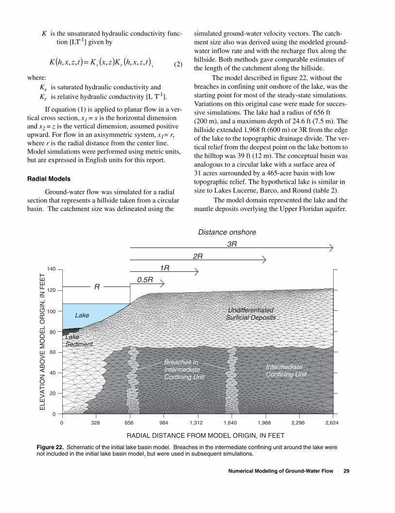
K is the unsaturated hydraulic conductivity func-tion [LT-1] given by
, (2)
where: Ks is saturated hydraulic conductivity andKr is relative hydraulic conductivity [L T-1].
If equation (1) is applied to planar flow in a ver-tical cross section, x1 = x is the horizontal dimension and x2 = z is the vertical dimension, assumed positive upward. For flow in an axisymmetric system, x1= r, where r is the radial distance from the center line. Model simulations were performed using metric units, but are expressed in English units for this report.
Radial Models
Ground-water flow was simulated for a radial section that represents a hillside taken from a circular basin. The catchment size was delineated using the
simulated ground-water velocity vectors. The catch-ment size also was derived using the modeled ground-water inflow rate and with the recharge flux along the hillside. Both methods gave comparable estimates of the length of the catchment along the hillside.
The model described in figure 22, without the breaches in confining unit onshore of the lake, was the starting point for most of the steady-state simulations. Variations on this original case were made for succes-sive simulations. The lake had a radius of 656 ft (200 m), and a maximum depth of 24.6 ft (7.5 m). The hillside extended 1,968 ft (600 m) or 3R from the edge of the lake to the topographic drainage divide. The ver-tical relief from the deepest point on the lake bottom to the hilltop was 39 ft (12 m). The conceptual basin was analogous to a circular lake with a surface area of 31 acres surrounded by a 465-acre basin with low topographic relief. The hypothetical lake is similar in size to Lakes Lucerne, Barco, and Round (table 2).
The model domain represented the lake and the mantle deposits overlying the Upper Floridan aquifer.
( ) ( ) ( )tzxhKzxKtzxhK rs ,,,,,,, =
UndifferentiatedSurficial DepositsLake
LakeSediment
0 328 656 984 1,312 1,640 1,968 2,296 2,624
40
120
140
60
20
100
80
0
RADIAL DISTANCE FROM MODEL ORIGIN, IN FEET
ELE
VA
TIO
N A
BO
VE
MO
DE
L O
RIG
IN, I
N F
EE
T
R0.5R
1R
2R
3R
Distance onshore
Breaches inIntermediateConfining Unit
IntermediateConfining Unit
Figure 22. Schematic of the initial lake basin model. Breaches in the intermediate confining unit around the lake were not included in the initial lake basin model, but were used in subsequent simulations.
Numerical Modeling of Ground-Water Flow 29

The intermediate confining unit, in the lower part of the model, was 65 ft thick. Directly below the lake, the intermediate confining unit has been breached by a sinkhole structure and replaced with surficial deposits. Surficial sand and clay deposits ranging in thickness from 40 to 60 ft overlie the intermediate confining unit. Lake sediment underlies the lake, and this sedi-ment has a much lower hydraulic conductivity than the encompassing surficial deposits.
The hydraulic characteristics of the hydrogeo-logic units used in the model are shown in table 4 and are loosely adapted from the Lake Barco basin. The unconsolidated surficial deposits were assumed to be predominantly sand with a hydraulic conductivity of 3 ft/d. The daily flux of water entering the hillside was based on 35 percent of the average annual rainfall rate of 52 in/yr. The head in the Upper Floridan aquifer was 4.9 ft below the lake stage. With these hydraulic parameters set, the Kh of the intermediate confining unit was adjusted until the overall water-table slope between the lake and hilltop was about 0.5 percent. The highest incremental water-table slope simulated in the basin model (about 1.5 percent near the lake) was similar to the maximum values in the 14 surveyed lakes (table 2). The resulting saturated horizontal hydraulic conductivity (Kh) for the intermediate con-fining unit was 0.2 ft/d, and was comparable to values determined in field studies (for example, Amy Swancar and T.M. Lee, USGS, written commun., 2002).
For transient simulations, the hillside shown in figure 22 was changed to test the effect of the topography on the simulated inflow to the lake. The initial lake basin model simulated a hillside with relatively low relief above the lake surface. In a variation on the initial lake basin model, the land surface close to the lake shore was lowered to reduce the unsaturated zone thickness in the near shore region (fig. 23a). The hillside of the initial lake basin model was then raised, increasing the unsaturated zone thickness at the top of the hill from about 7 to 50 ft (fig. 23b). The near shore region of the high hillside was also lowered (fig. 23b).
The unsaturated soil characteristics used in the model were from a Candler series sand (deeply weathered, acidic, uncoated, Typic Quartzipsam-ments) collected at a site in Orange County, in the Central Lake District (Lee, 2000; Sumner, 1996). This soil was used to simulate the shallow surficial deposits in the model. Below the elevation of the lake water surface, porous media in the model typi-cally were saturated, and Kh and anisotropy were the only soil parameters required. The anisotropy in the saturated zone (Kh/Kv) was assumed to be 10. An anisotropy of one was assumed in the unsatur-ated zone.
Changing the geometry of the model domain by changing the contour of the lake bottom or hill-side, or the overall height or length of the section, required a new model with a new finite-element mesh. To prevent changes in modeled fluxes from becoming an artifact of differences in the finite-ele-ment meshes used in simulations, the triangular ele-ments used in the meshes were kept as small as practical, and the size of triangular elements used in different model variations was kept comparable. The dimensions of mesh elements were reduced in preliminary model runs until consistent lake fluxes could be produced using a variety of meshes with the same tolerances on mesh design. The dimen-sions of the mesh elements then were kept compara-ble between models by keeping the spacing between boundary nodes similar.
The model has a mesh generator algorithm that constructs the finite-element mesh based on user-defined parameters. The dimensions of the finite-element grid were smallest in the shallow surficial deposits and along the lake bottom, where the heights of the triangles (measured vertically),
Table 4. Hydraulic parameters used in the initial lake basin model[ft-1, per foot; m-1, per meter; m/d, meters per day]
Unsaturated Hydraulic Parameters1
1All initial values were taken from a simulation of Lake Barco by Lee (2000). Unsaturated zone is within the undifferentiated surficial deposits only.
Saturation moisture content 0.32Residual moisture content 0.034Alpha2
2Alpha and N are curve-fitting parameters developed byvan Genuchten and others (1991).
1.0 ft-1 (3.27 m-1)N2 4.68
Saturated Horizontal Hydraulic Conductivity1 (foot per day) (meters per day)
Surficial aquifer 3 (0.91)Intermediate confining unit 0.2 (0.06)Organic sediment 0.03 (0.009)Upper Floridan aquifer3
3Boundary nodes only.
833 (254)
30 Factors Affecting Ground-Water Exchange and Catchment Size for Florida Lakes in Mantled Karst Terrain
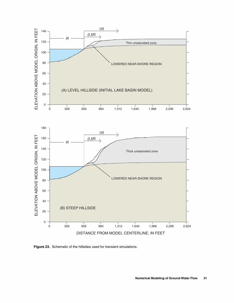
40
120
140
160
180
60
20
100
80
0
ELE
VA
TIO
N A
BO
VE
MO
DE
L O
RIG
IN, I
N F
EE
TE
LEV
AT
ION
AB
OV
E M
OD
EL
OR
IGIN
, IN
FE
ET
0 328 656 984 1,312 1,640 1,968 2,296 2,624
DISTANCE FROM MODEL CENTERLINE, IN FEET
40
120
140
60
20
100
80
00 328 656 984 1,312 1,640 1,968 2,296 2,624
(B) STEEP HILLSIDE
R0.5R
1R
LOWERED NEAR-SHORE REGION
LOWERED NEAR-SHORE REGION
R0.5R
1R
Thin unsaturated zone
Thick unsaturated zone
(A) LEVEL HILLSIDE (INITIAL LAKE BASIN MODEL)
Figure 23. Schematic of the hillsides used for transient simulations.
Numerical Modeling of Ground-Water Flow 31

∆z, were less than or equal to (<) 0.82 ft and the widths of the triangles, ∆r, were < 16.4 ft. The larg-est mesh dimensions (∆z < 6.6 ft, ∆r < 131 ft) were generated in the intermediate confining unit beneath the hilltop. All models used a mesh distortion vari-able of 0.04 or 0.05. This variable gives the mesh a vertical to horizontal ratio of 1 to 20 or 1 to 25. All of the simulations with a long hillside (radial dis-tance 2,624 ft or 800 m) used 220 boundary nodes. In shorter basins (discussed in the following section on Effect of Basin Size), the number of boundary nodes was reduced to maintain a comparable mesh density (number of triangular elements).
Model Boundaries
In all simulations, lateral model boundaries were located beneath the center of the lake and beneath the topographically defined drainage divide (figs. 22 and 23). At these boundaries, the flow in the unsaturated and saturated zones was assumed to be predominantly vertical, as observed in field studies. Thus, no flow occurred across these lateral boundaries. The lower model boundary represented the Upper Floridan aquifer, and was assigned a specified pressure head to reflect the potentiometric head in the aquifer. The total head along this boundary was assumed to be 4.9 ft below the lake stage for the initial model run, and was varied in subsequent runs. Where the lake submerges the lowest part of the hillside, the boundary was a specified pressure head distributed along the lake bottom to reflect hydrostatic conditions of the lake stage. The lake stage was assumed to be 106.63 ft (32.5 m) above the model origin for most simulations.
The water flux rate along the hillside differed in the steady-state and transient model simulations. In the steady-state simulations, the hillside received a con-stant flux of water. Losses to evaporation and transpi-ration were not simulated but were subtracted directly from the flux rate applied to the hillside. For most of the steady-state simulations, this net recharge rate (flux) was assumed to equal 0.0496 inches per day (in/d), and was equivalent to 35 percent of an average annual rainfall rate of 52 inches per year, based upon recharge estimates at Lake Barco (Lee, 1996). This flux was applied to the land surface and traveled through the unsaturated zone before arriving at the water table as a net recharge rate. There is no change in storage in the unsaturated zone under steady-state conditions, therefore the flux into the land surface at any time equaled the flux at the water table. For this
reason, the hillside topography had no affect on the water-table configuration for steady-state simulations.
Transient simulations used a time-variable spec-ified flux along the hillside to reflect the seasonal vari-ability of recharge. A flux rate approximating net daily recharge was applied to the land surface each day for a representative 273-day period (October 1, 1997 - June 30, 1998). The daily recharge rates applied to the land surface were those used by Amy Swancar and T.M. Lee, USGS, written commun., 2002, to simulate the saturated ground-water flow at Lake Starr, in Polk County. Daily recharge was computed as a variable percentage of the daily net precipitation in a manner referred to as the “threshold” method. With this method, the annual total recharge equaled about 50 percent of the average annual rainfall (Amy Swan-car and T.M. Lee, USGS, written commun., 2002). This recharge rate was higher than the 35 percent rate applied to the initial steady-state model, but compara-ble to the higher recharge cases considered in the steady-state simulations. The last 150 days or 5 months of the simulation provided the results for the transient analysis. The first 4 months (123 days) of the simulation were used to distance the model results from the effects of the initial conditions. Within the latter 5 months, the first 2 months had above average rainfall and the last 3 months were drier.
Unlike the steady-state model, the transient model simulates the arrival time and rate of recharge to the water table at different locations under the hillside (fig. 23). The flux arriving at the water table, and thus the transient water-table response, is affected by the daily recharge flux, the moisture storage in the unsat-urated zone, the depth of the water table below land surface, and the soil moisture characteristics (table 4). The initial pressure-head distribution for transient sim-ulations was the simulated steady-state pressure-head distribution for the model.
Limits to Hypothetical Steady-State Simulations
Hypothetical steady-state modeling results were compared to explore the effect of physical and hydro-geological factors on the magnitude of ground-water inflow and catchment size. For example, consider two identical hypothetical lake basin models. If a single physical factor in one of the two basin models is altered, the effect it has on the simulated ground-water flow can be compared to the unaltered model.
Properly interpreting the model results, how-ever, requires considering the effect of the lake stage boundary on model simulations. In steady-state model
32 Factors Affecting Ground-Water Exchange and Catchment Size for Florida Lakes in Mantled Karst Terrain
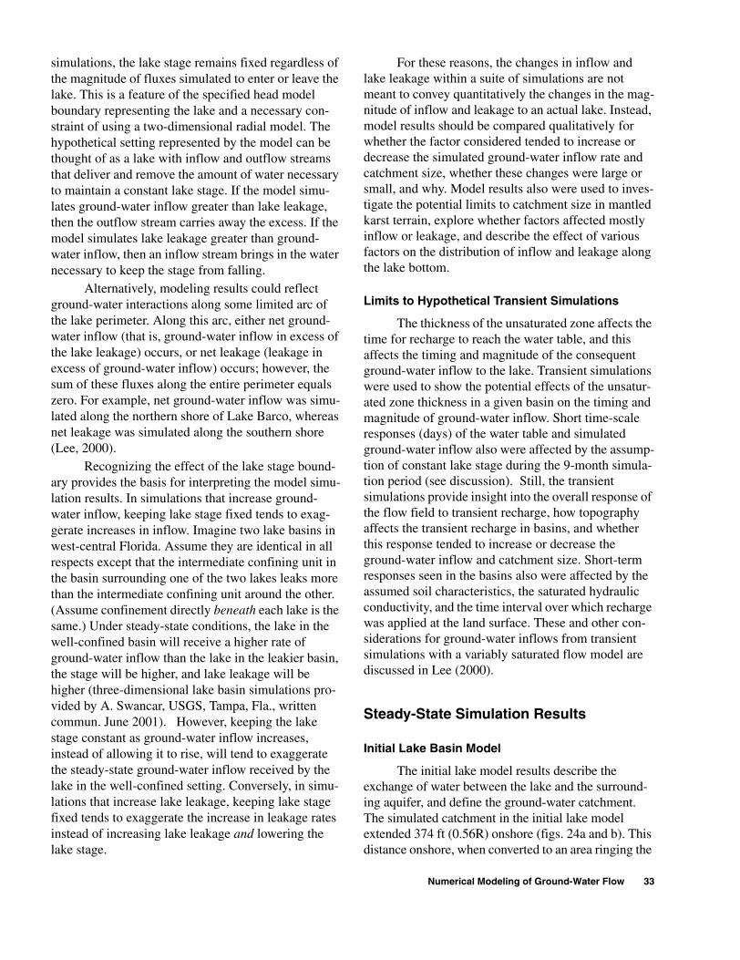
simulations, the lake stage remains fixed regardless of the magnitude of fluxes simulated to enter or leave the lake. This is a feature of the specified head model boundary representing the lake and a necessary con-straint of using a two-dimensional radial model. The hypothetical setting represented by the model can be thought of as a lake with inflow and outflow streams that deliver and remove the amount of water necessary to maintain a constant lake stage. If the model simu-lates ground-water inflow greater than lake leakage, then the outflow stream carries away the excess. If the model simulates lake leakage greater than ground-water inflow, then an inflow stream brings in the water necessary to keep the stage from falling.
Alternatively, modeling results could reflect ground-water interactions along some limited arc of the lake perimeter. Along this arc, either net ground-water inflow (that is, ground-water inflow in excess of the lake leakage) occurs, or net leakage (leakage in excess of ground-water inflow) occurs; however, the sum of these fluxes along the entire perimeter equals zero. For example, net ground-water inflow was simu-lated along the northern shore of Lake Barco, whereas net leakage was simulated along the southern shore (Lee, 2000).
Recognizing the effect of the lake stage bound-ary provides the basis for interpreting the model simu-lation results. In simulations that increase ground-water inflow, keeping lake stage fixed tends to exag-gerate increases in inflow. Imagine two lake basins in west-central Florida. Assume they are identical in all respects except that the intermediate confining unit in the basin surrounding one of the two lakes leaks more than the intermediate confining unit around the other. (Assume confinement directly beneath each lake is the same.) Under steady-state conditions, the lake in the well-confined basin will receive a higher rate of ground-water inflow than the lake in the leakier basin, the stage will be higher, and lake leakage will be higher (three-dimensional lake basin simulations pro-vided by A. Swancar, USGS, Tampa, Fla., written commun. June 2001). However, keeping the lake stage constant as ground-water inflow increases, instead of allowing it to rise, will tend to exaggerate the steady-state ground-water inflow received by the lake in the well-confined setting. Conversely, in simu-lations that increase lake leakage, keeping lake stage fixed tends to exaggerate the increase in leakage rates instead of increasing lake leakage and lowering the lake stage.
For these reasons, the changes in inflow and lake leakage within a suite of simulations are not meant to convey quantitatively the changes in the mag-nitude of inflow and leakage to an actual lake. Instead, model results should be compared qualitatively for whether the factor considered tended to increase or decrease the simulated ground-water inflow rate and catchment size, whether these changes were large or small, and why. Model results also were used to inves-tigate the potential limits to catchment size in mantled karst terrain, explore whether factors affected mostly inflow or leakage, and describe the effect of various factors on the distribution of inflow and leakage along the lake bottom.
Limits to Hypothetical Transient Simulations
The thickness of the unsaturated zone affects the time for recharge to reach the water table, and this affects the timing and magnitude of the consequent ground-water inflow to the lake. Transient simulations were used to show the potential effects of the unsatur-ated zone thickness in a given basin on the timing and magnitude of ground-water inflow. Short time-scale responses (days) of the water table and simulated ground-water inflow also were affected by the assump-tion of constant lake stage during the 9-month simula-tion period (see discussion). Still, the transient simulations provide insight into the overall response of the flow field to transient recharge, how topography affects the transient recharge in basins, and whether this response tended to increase or decrease the ground-water inflow and catchment size. Short-term responses seen in the basins also were affected by the assumed soil characteristics, the saturated hydraulic conductivity, and the time interval over which recharge was applied at the land surface. These and other con-siderations for ground-water inflows from transient simulations with a variably saturated flow model are discussed in Lee (2000).
Steady-State Simulation Results
Initial Lake Basin Model
The initial lake model results describe the exchange of water between the lake and the surround-ing aquifer, and define the ground-water catchment. The simulated catchment in the initial lake model extended 374 ft (0.56R) onshore (figs. 24a and b). This distance onshore, when converted to an area ringing the
Numerical Modeling of Ground-Water Flow 33
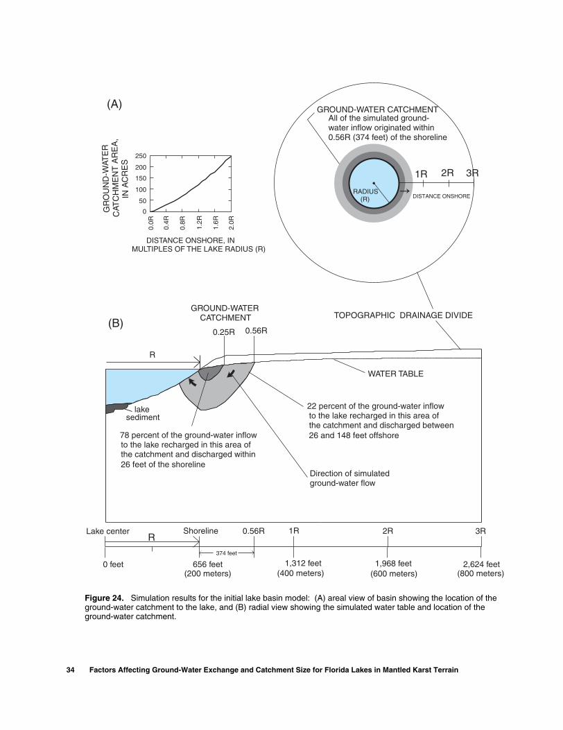
(A)
(B)
2,624 feet1,968 feet1,312 feet656 feet0 feet(200 meters) (400 meters) (600 meters) (800 meters)
0.56R
ShorelineLake centerR
1R0.56R 2R 3R
0.25R
the catchment and discharged within26 feet of the shoreline
to the lake recharged in this area of78 percent of the ground-water inflow
the catchment and discharged between 26 and 148 feet offshore
to the lake recharged in this area of22 percent of the ground-water inflow
1R 2R 3R
GROUND-WATER CATCHMENTG
RO
UN
D-W
ATE
RC
ATC
HM
EN
T A
RE
A,
IN A
CR
ES
DISTANCE ONSHORE, INMULTIPLES OF THE LAKE RADIUS (R)
250
200
150
100
50
0
0.0R
0.4R
0.8R
1.2R
1.6R
2.0R
GROUND-WATERCATCHMENT TOPOGRAPHIC DRAINAGE DIVIDE
RADIUS(R)
WATER TABLE
lakesediment
374 feet
All of the simulated ground-water inflow originated within0.56R (374 feet) of the shoreline
R
Direction of simulatedground-water flow
DISTANCE ONSHORE
Figure 24. Simulation results for the initial lake basin model: (A) areal view of basin showing the location of the ground-water catchment to the lake, and (B) radial view showing the simulated water table and location of the ground-water catchment.
34 Factors Affecting Ground-Water Exchange and Catchment Size for Florida Lakes in Mantled Karst Terrain

lake, described the size of the catchment. The catch-ment area increases as the square of the catchment distance onshore (fig. 24a). Ground water entering the shallow lake bottom originated as recharge in the near shore region of the catchment. Ground water entering the deeper regions of the lake bottom originated as recharge farther up the hillside (fig. 24b). For the initial model simulation, the ground-water inflow rate exceeded the lake leakage rate (8,470 and 4,940 ft3/d/360 degrees, respectively) and the excess was equivalent to a 27.5-in/yr rise over the lake area. Variations on this initial simulation could seem to pro-duce more realistic results, with balanced leakage and inflow. In this analysis, however, no one simulation is necessarily better than another, as all provide a measure of the tendency of the flow field to generate inflow or leakage under different physical conditions.
The velocity of the ground-water inflow was highest at the water’s edge, and decreased with dis-tance offshore (fig. 25). Inflow stopped about 148 ft offshore, where the velocity vectors reversed from inflow to leakage. Leakage velocity increased from this point toward the lake center and peaked just before reaching the lake sediment. The radial model
simulated a large volume of ground water entering the lake near the shoreline for two reasons. First, the ground-water velocity was high in this part of the lake, and second, the area of inflow was large; that is, the area of the lake bottom near the shoreline occupied a relatively large fraction of the total lake bottom area (fig. 25).
Effect of Recharge Rate
Simulated ground-water inflow to the lake approximately tripled when the steady-state recharge rate was increased from 25 percent to 45 percent of the annual rainfall (fig. 26). Greater recharge also increased the radius of the ground-water catchment. The catchment extended about 290 ft onshore of the lake (0.44R) when the recharge was 25 percent of the annual rainfall. It reached 440 ft onshore (0.66R) when recharge was 45 percent of the annual rainfall. For the lake basin dimensions used in this model, this trans-lates into an increase in the catchment area from 33 to 54 acres or a 60 percent increase in size.
Under the assumption of constant lake stage, the simulated lake leakage decreased only slightly (<10 per-cent) in response to the increased recharge (fig. 26).
SH
OR
ELI
NE
Lake
PEAK LEAKAGE RATENEAR SEDIMENT LENS
MINIMALOUTFLOWTHROUGHSEDIMENTLENS
0 100 200 300 400 500 600 700
20
15
10
5
0
-5
-10
PEAK INFLOW RATEAT SHORELINE
DIRECTION OF SIMULATED GROUND-WATER FLOW
LEAKAGE INFLOW
FLO
WR
AT
E T
HR
OU
GH
T
HE
LA
KE
BO
TT
OM
,IN
CU
BIC
FE
ET
PE
R D
AY
PE
R R
AD
IAL
DE
GR
EE
DISTANCE FROM THE MODEL CENTERLINE,IN FEET
0
5
10
15
20
25
30
35
40
25 30 35 40 45
ANNUAL RECHARGE, AS A PERCENTAGE OF THE
AVERAGE ANNUAL RAINFALL
CA
TC
HM
EN
TD
IST
AN
CE
,IN
R U
NIT
S
00.30.60.91.2
INITIALMODEL
FLO
W R
AT
E,
IN C
UB
IC F
EE
T P
ER
DA
Y,
PE
R R
AD
IAL
DE
GR
EE LAKE LEAKAGE
GROUND-WATER INFLOW
Figure 25. Ground-water flow distribution along the lakebed for the initial lake basin model. Arrows show ground-water flow direction.
Figure 26. Simulated ground-water inflow and leakage rates, and catchment sizes for modeled lakes with different recharge rates.
Numerical Modeling of Ground-Water Flow 35

This small decrease occurred because at the higher of the two recharge rates, ground water entered the lake-bed farther offshore (172 ft compared to 101 ft), reduc-ing the area of lake bottom that leaked. The reduction in leakage was relatively small, however, because velocities were low in the area of the lake bottom where this transition from leakage to inflow occurred. The greatest increase in ground-water inflow was near the lake margin where velocity increased because of the increased water-table slope.
Greater recharge typically is coupled with a rise in the potentiometric surface of the Upper Floridan aquifer, particularly in basins where greater rainfall would lessen ground-water pumping for irrigation. Both effects, when sustained, would tend to raise lake stage, and increase the magnitude of ground-water inflow and catchment size. The steady-state losses from the lake would rise accordingly (see section Effect of Upper Floridan Aquifer Boundary Condition).
Effect of Basin Size
For lake basins in which all other basin charac-teristics are equal, differences in the size of the topo-graphically defined basin can affect the magnitude of ground-water inflow and catchment size. In successive simulations, the lateral model boundary was set at dis-tances from the lakeshore ranging from 0.5R to 3.0R. The dimensions of the modeled basins are shown on figure 22. Increasing the basin size from 0.5R to 1R approximately doubled the simulated ground-water inflow (fig. 27) and increased the ground-water catch-ment size from 0.24R to 0.44R. Increasing the size of the basin from 1R to 2R increased the steady-state inflow again but by about 35 percent and increased the catchment size to 0.56R. Increasing the basin size from 2R to 3R resulted in only a 6 percent increase in the simulated inflow, suggesting that successive increases in basin size would generate little additional inflow for this setting (fig. 27).
The shape of the steady-state water table was independent of the slope of the land surface or the unsaturated zone thickness. The shape depended only on the boundary conditions, the distribution of hydrau-lic conductivity in the model, and basin size. Increas-ing the size of the basin increased the simulated water-table elevation at the drainage divide by moving the divide beyond the region where the water table was deformed by ground-water discharge to the lake. The higher water table at the divide, in turn, increased the water-table gradient near the lake, which increased
inflow. For simulations beyond 2R, the rise in the sim-ulated water table at the drainage divide was relatively small for each additional R of basin size. As a result, ground-water inflow only increased marginally as basin radius was increased beyond 2R.
Increasing basin size also slightly decreased the tendency for the simulated lakes to leak. Because greater basin size tended to increase ground-water inflow, it also tended to reduce the area of the lakebed through which leakage occurred. Leakage was mini-mally responsive to basin radius, decreasing by about 8 percent as basin radius increased from 0.5R to 3R.
Each of the 14 lakes described had within its basin a shortest hillside < 1R in length (table 2). A nearby lake can shorten the distance to the basin drain-age divide along a hillside, potentially limiting the size of the ground-water catchment and ground-water inflow. If the adjacent lake were at a higher stage, however, it could increase the catchment size relative to a short hillside with no lake. An upgradient lake does not imply lateral ground-water flow between the lakes. Instead, the water table below the hillside may be maintained higher than it would be beneath a short hillside with no upgradient lake. This higher water
0
5
10
15
20
25
30
35
40
0.5R 1R 2R 3R
SIZE OF TOPOGRAPHICALLY-DEFINED BASIN,
IN UNITS OF LAKE RADIUS (R)
00.30.60.91.2
FLO
W R
AT
E,
IN C
UB
IC F
EE
T P
ER
DA
Y,
PE
R R
AD
IAL
DE
GR
EE
CA
TC
HM
EN
TD
IST
AN
CE
,IN
R U
NIT
S
INITIALMODEL
LAKE LEAKAGE
GROUND-WATER INFLOW
Figure 27. Simulated ground-water inflow and leakage rates, and catchment sizes for modeled lakes with different size basins.
36 Factors Affecting Ground-Water Exchange and Catchment Size for Florida Lakes in Mantled Karst Terrain
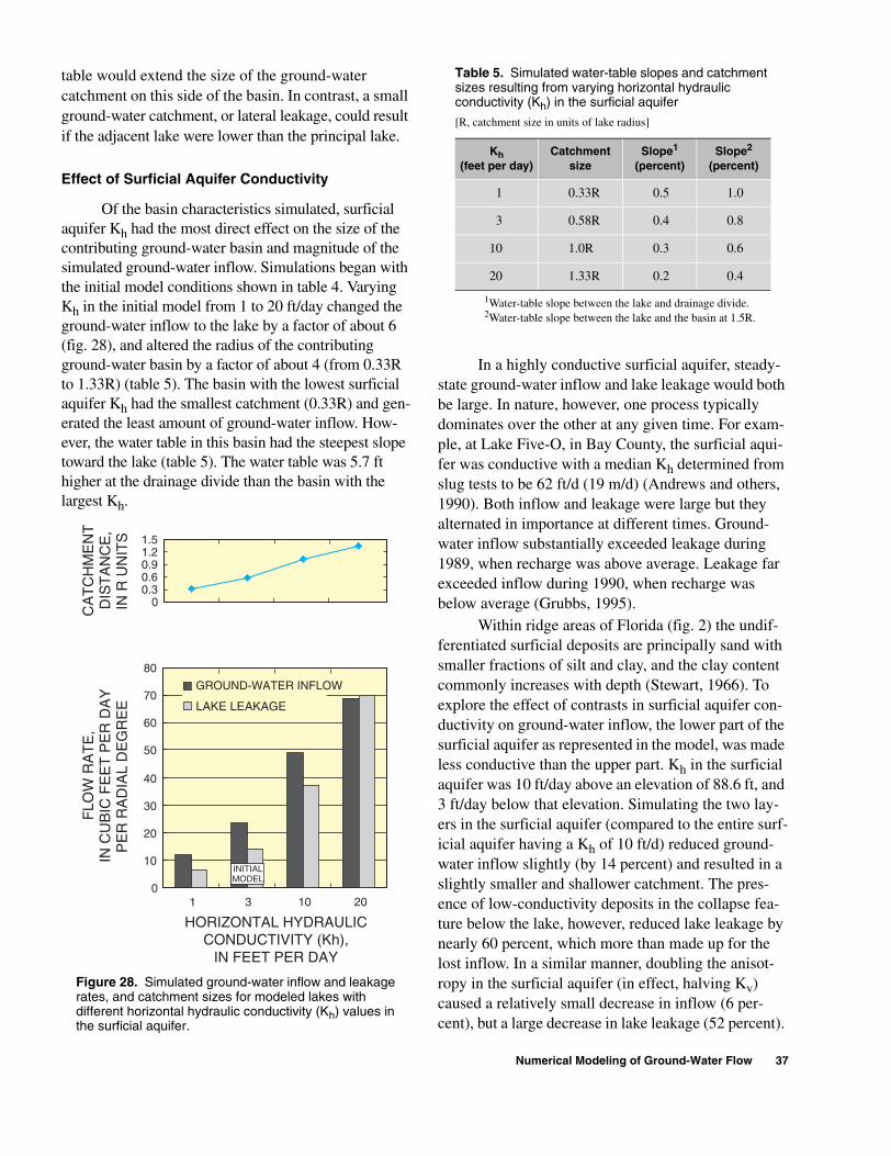
table would extend the size of the ground-water catchment on this side of the basin. In contrast, a small ground-water catchment, or lateral leakage, could result if the adjacent lake were lower than the principal lake.
Effect of Surficial Aquifer Conductivity
Of the basin characteristics simulated, surficial aquifer Kh had the most direct effect on the size of the contributing ground-water basin and magnitude of the simulated ground-water inflow. Simulations began with the initial model conditions shown in table 4. Varying Kh in the initial model from 1 to 20 ft/day changed the ground-water inflow to the lake by a factor of about 6 (fig. 28), and altered the radius of the contributing ground-water basin by a factor of about 4 (from 0.33R to 1.33R) (table 5). The basin with the lowest surficial aquifer Kh had the smallest catchment (0.33R) and gen-erated the least amount of ground-water inflow. How-ever, the water table in this basin had the steepest slope toward the lake (table 5). The water table was 5.7 ft higher at the drainage divide than the basin with the largest Kh.
0
10
20
30
40
50
60
70
80
00.30.60.91.21.5
FLO
W R
AT
E,
IN C
UB
IC F
EE
T P
ER
DA
YP
ER
RA
DIA
L D
EG
RE
E
CA
TC
HM
EN
TD
IST
AN
CE
,IN
R U
NIT
S
HORIZONTAL HYDRAULICCONDUCTIVITY (Kh),
IN FEET PER DAY
1 3 10 20
INITIALMODEL
LAKE LEAKAGE
GROUND-WATER INFLOW
Figure 28. Simulated ground-water inflow and leakage rates, and catchment sizes for modeled lakes with different horizontal hydraulic conductivity (Kh) values in the surficial aquifer.
In a highly conductive surficial aquifer, steady-state ground-water inflow and lake leakage would both be large. In nature, however, one process typically dominates over the other at any given time. For exam-ple, at Lake Five-O, in Bay County, the surficial aqui-fer was conductive with a median Kh determined from slug tests to be 62 ft/d (19 m/d) (Andrews and others, 1990). Both inflow and leakage were large but they alternated in importance at different times. Ground-water inflow substantially exceeded leakage during 1989, when recharge was above average. Leakage far exceeded inflow during 1990, when recharge was below average (Grubbs, 1995).
Within ridge areas of Florida (fig. 2) the undif-ferentiated surficial deposits are principally sand with smaller fractions of silt and clay, and the clay content commonly increases with depth (Stewart, 1966). To explore the effect of contrasts in surficial aquifer con-ductivity on ground-water inflow, the lower part of the surficial aquifer as represented in the model, was made less conductive than the upper part. Kh in the surficial aquifer was 10 ft/day above an elevation of 88.6 ft, and 3 ft/day below that elevation. Simulating the two lay-ers in the surficial aquifer (compared to the entire surf-icial aquifer having a Kh of 10 ft/d) reduced ground-water inflow slightly (by 14 percent) and resulted in a slightly smaller and shallower catchment. The pres-ence of low-conductivity deposits in the collapse fea-ture below the lake, however, reduced lake leakage by nearly 60 percent, which more than made up for the lost inflow. In a similar manner, doubling the anisot-ropy in the surficial aquifer (in effect, halving Kv) caused a relatively small decrease in inflow (6 per-cent), but a large decrease in lake leakage (52 percent).
Table 5. Simulated water-table slopes and catchment sizes resulting from varying horizontal hydraulic conductivity (Kh) in the surficial aquifer
[R, catchment size in units of lake radius]
Kh(feet per day)
Catchmentsize
Slope1
(percent)
1Water-table slope between the lake and drainage divide.
Slope2
(percent)
2Water-table slope between the lake and the basin at 1.5R.
1 0.33R 0.5 1.0
3 0.58R 0.4 0.8
10 1.0R 0.3 0.6
20 1.33R 0.2 0.4
Numerical Modeling of Ground-Water Flow 37

Effect of Intermediate Confining Unit
The conductivity of the intermediate confining unit surrounding the lake affected the size of the ground-water catchment and the magnitude of ground-water inflow (fig. 29). In these simulations, the range in confining unit Kv was approximately one order of mag-nitude (0.010 ft/d to 0.098 ft/d). Where the intermediate confining unit was least permeable, and Kv was at the lowest simulated value (0.01 ft/d), the catchment extended 1.1R onshore and contributed slightly more than twice the inflow as in the initial model simulation. For this simulation, about 22 percent of the recharge entering the hillside discharged into the lake as ground-water inflow. As the conductivity of the intermediate confining unit increased, more of the recharge went to the Upper Floridan aquifer, and less discharged into the lake. For example, increasing the Kv of the intermediate confining unit from 0.0164 to 0.023 ft/day (about 40 percent increase) reduced ground-water inflow by 38 percent (fig. 29), and reduced the size of the ground-water catchment from 0.71R to 0.48R.
Moderately increasing the Kv of the intermedi-ate confining unit in the basin (from 0.01 to 0.023 ft/day) reduced ground-water inflow by a factor of about 3, but caused only a small increase in lake leakage (13 percent) (fig. 29). The decreased inflow caused the lake leakage to advance closer to shore (from 195 ft to 124 ft offshore). However, the area of the lake bottom where leakage replaced inflow was where the flow field had the lowest velocities. As a result, the shoreward advance of the area of lake leak-age with increasing Kv in the basin had a relatively small effect on total lake leakage. Inflow was still occurring, although at a lesser rate, in a large area con-centric to the shoreline where the velocity and incre-mental bottom area were relatively large. Total lake leakage was still affected primarily by the head differ-ence between the lake and the Upper Floridan aquifer and the Kv directly beneath the lake, neither of which had changed from the initial model conditions.
When the Kv in the basin was increased further, leakage increased substantially, because it began to occur not just through the deeper lakebed but closer to the shoreline. For example, when the Kv of the inter-mediate confining unit was raised to 0.066 ft/d, the water table fell 0.3 ft below the lake stage at the drain-age divide, causing a small outflow slope in the water table (-0.03 percent). Thus, lake leakage replaced ground-water inflow along the lake margin. Further
increases in the Kv of the intermediate confining unit increased the total lake leakage by increasing leakage near the shoreline (fig. 29). Only slight increases in leakage occurred in the deeper lakebed (fig. 30).
Changing the confinement in the surrounding basin affected both ground-water inflow and leakage fluxes through the shallow lakebed. Changing confine-ment directly beneath the lake, however, affected lake leakage more than ground-water inflow. Larger breaches in the intermediate confining unit directly beneath the lake increased the simulated leakage from the deeper areas of the lakebed (figs. 31 and 32). Increases in leakage had relatively little effect on the inflow until the breach became large enough to inter-cept inflow occurring nearer the shoreline (for exam-ple, 330-ft opening, figs. 31 and 32). The shape as well as the size of the opening in the intermediate confining unit also affected the simulated ground-water exchange. When the top of the breach was widened, the simulated leakage increased moderately (24 percent) (fig. 32, compare “185-ft opening” with “185 ft opening, wider top”).
00.30.60.91.2
0
10
20
30
40
50
60
X X X
VERTICAL HYDRAULICCONDUCTIVITY (Kv),
IN FEET PER DAY
0.01
00.
0164
0.01
97
0.02
30
0.03
28
0.06
60.
0820
0.09
8
FLO
W R
ATE
,IN
CU
BIC
FE
ET
PE
R D
AYP
ER
RA
DIA
L D
EG
RE
E
CAT
CH
ME
NT
DIS
TAN
CE
,IN
R U
NIT
S
GROUND-WATER INFLOW
LAKE LEAKAGE
INITIALMODEL
Figure 29. Simulated ground-water inflow and leakage rates, and catchment sizes for modeled lakes with different vertical hydraulic conductivity (Kv) values in the intermediate confining unit surrounding the lake. X indicates zero ground-water inflow.
38 Factors Affecting Ground-Water Exchange and Catchment Size for Florida Lakes in Mantled Karst Terrain

-10
-5
0
5
10
15
20
0 100 200 300 400 500 600 700
DISTANCE FROM THE MODEL CENTERLINE,IN FEET
Kv=0.02 FEET PER DAY
Kv=0.066 FEET PER DAY
Kv=0.098 FEET PER DAY
INFLOW
SH
OR
ELI
NE
LEAKA GE
FLO
W R
ATE
TH
RO
UG
HT
HE
LA
KE
BO
TTO
M,I
N C
UB
IC F
EE
T P
ER
DAY
PE
R R
AD
IAL
DE
GR
EE
Figure 30. Ground-water flow distribution along the lakebed for different vertical hydraulic conductivity (Kv) values in the intermediate confining unit surrounding the lake.
330
185 WITH WIDER TOP
185
115
SINKHOLE WIDTH AT MODEL BASE, IN FEET
EXPLANATION
40
120
140
60
20
100
80
0
ELE
VA
TIO
N A
BO
VE
MO
DE
L O
RIG
IN, I
N F
EE
T
0 328 656 984 1,312 1,640 1,968 2,296 2,624
DISTANCE FROM MODEL CENTERLINE, IN FEET
Lake Sediment
180
FE
ET
330
FE
ET
490
FE
ET
INTERMEDIATECONFINING UNIT
UNDIFFERENTIATEDSURFICIAL DEPOSITS
Figure 31. Different size collapse features beneath lake and various arrangements of lake sediment used in ground-water flow simulations.
Numerical Modeling of Ground-Water Flow 39
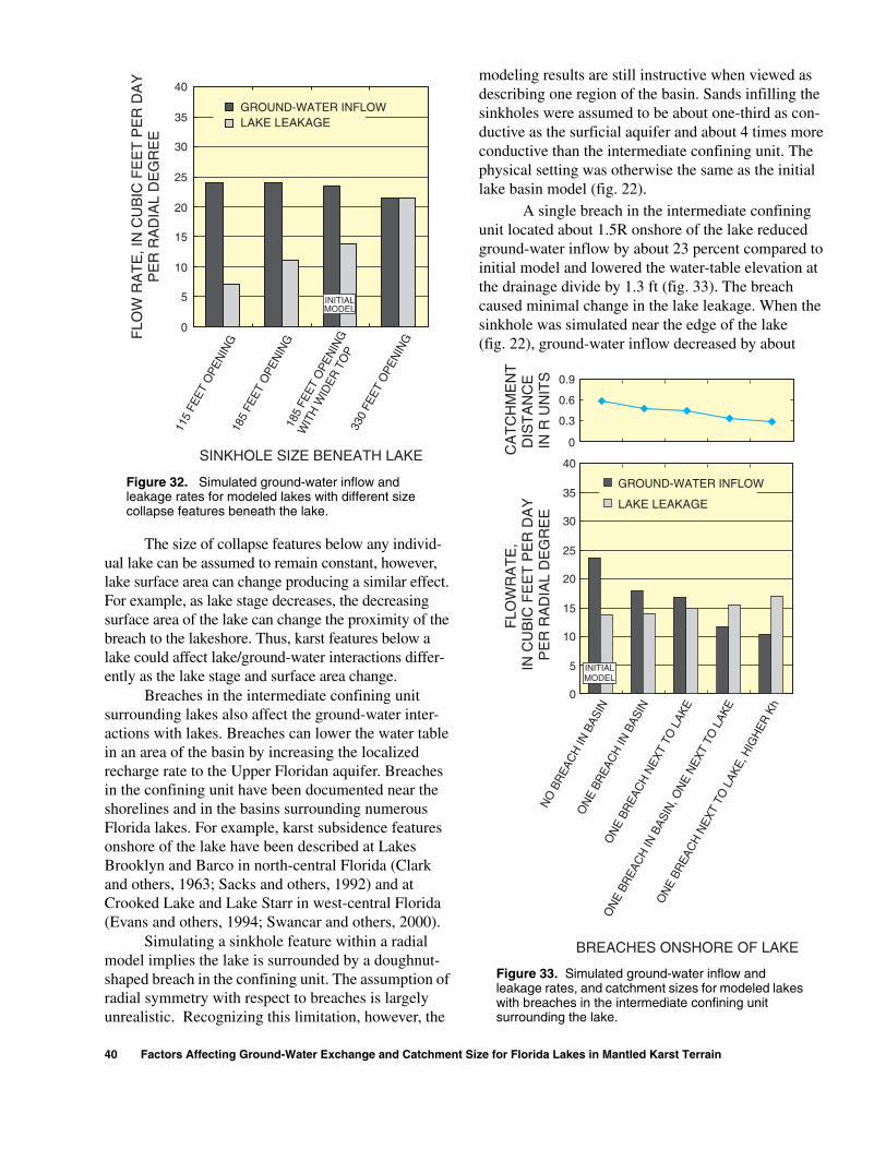
The size of collapse features below any individ-ual lake can be assumed to remain constant, however, lake surface area can change producing a similar effect. For example, as lake stage decreases, the decreasing surface area of the lake can change the proximity of the breach to the lakeshore. Thus, karst features below a lake could affect lake/ground-water interactions differ-ently as the lake stage and surface area change.
Breaches in the intermediate confining unit surrounding lakes also affect the ground-water inter-actions with lakes. Breaches can lower the water table in an area of the basin by increasing the localized recharge rate to the Upper Floridan aquifer. Breaches in the confining unit have been documented near the shorelines and in the basins surrounding numerous Florida lakes. For example, karst subsidence features onshore of the lake have been described at Lakes Brooklyn and Barco in north-central Florida (Clark and others, 1963; Sacks and others, 1992) and at Crooked Lake and Lake Starr in west-central Florida (Evans and others, 1994; Swancar and others, 2000).
Simulating a sinkhole feature within a radial model implies the lake is surrounded by a doughnut-shaped breach in the confining unit. The assumption of radial symmetry with respect to breaches is largely unrealistic. Recognizing this limitation, however, the
modeling results are still instructive when viewed as describing one region of the basin. Sands infilling the sinkholes were assumed to be about one-third as con-ductive as the surficial aquifer and about 4 times more conductive than the intermediate confining unit. The physical setting was otherwise the same as the initial lake basin model (fig. 22).
A single breach in the intermediate confining unit located about 1.5R onshore of the lake reduced ground-water inflow by about 23 percent compared to initial model and lowered the water-table elevation at the drainage divide by 1.3 ft (fig. 33). The breach caused minimal change in the lake leakage. When the sinkhole was simulated near the edge of the lake (fig. 22), ground-water inflow decreased by about
0
5
10
15
20
25
30
35
40
LAKE LEAKAGE
115
FEET
OPE
NIN
G18
5 FE
ET O
PEN
ING
185
FEET
OPE
NIN
G
WIT
H W
IDER
TO
P33
0 FE
ET O
PEN
INGF
LOW
RA
TE
, IN
CU
BIC
FE
ET
PE
R D
AY
PE
R R
AD
IAL
DE
GR
EE
INITIALMODEL
SINKHOLE SIZE BENEATH LAKE
GROUND-WATER INFLOW
Figure 32. Simulated ground-water inflow and leakage rates for modeled lakes with different size collapse features beneath the lake.
0
5
10
15
20
25
30
35
40
0.3
0.6
0.9
0
CA
TC
HM
EN
TD
IST
AN
CE
IN R
UN
ITS
FLO
WR
AT
E,
IN C
UB
IC F
EE
T P
ER
DA
YP
ER
RA
DIA
L D
EG
RE
E
INITIALMODEL
ON
E BR
EAC
H N
EXT
TO L
AKE,
HIG
HER
Kh
ON
E BR
EAC
H IN
BAS
IN, O
NE
NEX
T TO
LAK
E
ON
E BR
EAC
H N
EXT
TO L
AKE
ON
E BR
EAC
H IN
BAS
IN
NO
BR
EAC
H IN
BAS
IN
BREACHES ONSHORE OF LAKE
LAKE LEAKAGE
GROUND-WATER INFLOW
Figure 33. Simulated ground-water inflow and leakage rates, and catchment sizes for modeled lakes with breaches in the intermediate confining unit surrounding the lake.
40 Factors Affecting Ground-Water Exchange and Catchment Size for Florida Lakes in Mantled Karst Terrain

30 percent and lake leakage increased by about 8 per-cent. This sinkhole lowered the water-table elevation near the lake, but not near the drainage divide. Simu-lating both sinkholes in the basin halved the rate of ground-water inflow compared with the initial basin model and reduced the ground-water catchment size from 0.57R to 0.32R. Thus, the ability of catchments to deliver ground-water inflow to lakes could vary widely depending upon the size and location of the breaches, and the conductivity of the material infilling them.
Effect of Lake Sediment
The hydraulic conductivity of organic lake sedi-ment and the mineralized deposits that grade away from them can be very low (Winter, 1978). Thus, a lake with a thicker and more extensive area of organic sediment should leak more slowly than an identical lake with thinner, patchier, or more conductive sedi-ments.
To test the effect of lake sediment on lake and ground-water interactions, the Kh of the sediment lens in the initial model (0.029 ft/day) was varied by greater than 2 orders of magnitude from 0.0148 ft/d to 2.98 ft/d. Increasing the sediment Kv increased the flow velocity and leakage through the sediment lens, but added little to the total leakage simulated for the lake because of the small size of the sediment lens. In the initial model set-ting, the sediment lens extended about 180 ft from the model centerline and covered an area equivalent to about 8 percent of the lake surface area. The lens was about 6.6 ft thick at the center of the lake and thinned with dis-tance from the center (fig. 22). Removing the small sedi-ment lens altogether made little difference to the total leakage. Almost all of the lake leakage occurred in the area concentric to the sediment lens (from 164 to 328 ft from the centerline of the lake) which covered roughly 56 percent of the lake bottom area.
The size of the sediment lens had a greater effect on leakage than the conductivity of the small, initial sediment lens. When the sediment lens was extended to 330 ft and 490 ft from the centerline, lake leakage was reduced by about 20 percent and 30 percent, respectively (figs. 31 and 34). When the edge of the 490-ft sediment lens was made 1-2 ft thicker, leakage decreased by an additional 15 percent (fig. 34). Increasing the size of the sediment lens tended to slightly reduce ground-water inflow (3 percent reduc-tion between the 180-ft and 490-ft simulation), but
loss of inflow was small compared with the dimin-ished leakage (fig. 34).
Effect of Upper Floridan Aquifer Boundary Condition
In steady-state simulations, the model boundary representing the potentiometric level (head) of the Upper Floridan aquifer greatly affected the size of the ground-water catchment and magnitude of ground-water inflow to the lake, as well as the magnitude of lake leakage (fig. 35). Raising the head in the Upper Floridan aquifer in the initial model by 3.3 ft, from 101.7 to 105 ft, reduced the head difference between the lake and the Upper Floridan aquifer from 4.9 ft to 1.6 ft. The higher head in the Upper Floridan aquifer increased the simulated ground-water inflow by about 50 percent, and increased the catchment size from 0.56R to 0.82R (fig. 35). Raising the head in the Upper Floridan aquifer also reduced lake leakage to about one-third of the amount in the initial lake basin model. Lowering the Upper Floridan aquifer head to 98.4 ft, or 3.3 ft below the initial model condition, halved the amount of ground-water inflow to the lake compared to the initial model and reduced the ground-water catchment size from 0.58R to 0.35R. Leakage losses, in turn, almost doubled (factor of 1.8). Lower-ing the Upper Floridan aquifer head boundary further
0
5
10
15
20
25
30
35
40
180 330 490 490Thicker
EXTENT OF SEDIMENTFROM MODEL CENTERLINE,
IN FEET
INITIALMODEL
FLO
W R
AT
E, I
N C
UB
IC F
EE
T P
ER
DA
YP
ER
RA
DIA
L D
EG
RE
E LAKE LEAKAGE
GROUND-WATER INFLOW
Figure 34. Simulated ground-water inflow and leakage rates for modeled lakes with different arrangements of lake sediment.
Numerical Modeling of Ground-Water Flow 41

to 95.1 ft, or 11.5 ft below lake stage, reduced the ground-water inflow to 16 percent of the initial amount and reduced the catchment size to 0.12R. Leakage increased by a factor of 2.7 from the initial simulation.
Lowering the head of the Upper Floridan aquifer caused lake leakage to increase and extend closer to the shoreline. When the head in the Upper Floridan aquifer was at 1.6 ft below lake stage, 56 percent of the overall lakebed received ground-water inflow and the remaining 44 percent leaked. When the head was 11.5 ft below lake stage, inflow occurred through only 6 percent of the lakebed, and 94 percent of the lakebed leaked. Lowering the head in the Upper Floridan aqui-fer reduced ground-water inflow to the lake by induc-ing greater flow between the surficial and Upper Floridan aquifers and thus lowering the water-table elevation. Further reductions in the head, therefore, would lower the water table below the (constant) lake stage resulting in leakage through 100 percent of the lake bottom.
In actual lake basins, the potentiometric level of the Upper Floridan aquifer is rarely steady. In areas
with pumping, the Upper Floridan aquifer head is often substantially lowered for periods of weeks or months during the dry spring season, but rises during the rainy summer. For example, the daily average head of the Upper Floridan aquifer was between 5 and 7 ft below the level of Lake Lucerne for most of the 1986 water year. During April and May 1986, and as a result of local pumping for citrus irrigation, daily heads aver-aged 10 to 12 ft below lake stage, with daily maximum values of 14 ft. During June and with the onset of the rainy season, the downward head difference averaged 9 ft. Although the lowest head conditions lasted only about 2 months, the lake and surrounding ground-water system had time to respond to the stress. The heads were lowered not only in the Upper Floridan aquifer but also around and beneath the lake, and monthly leakage nearly doubled during April and May compared with February and March of 1986 (Lee and Swancar, 1997).
Effect of Lake Stage
Lake levels can be raised artificially by damming surface-water outflows or by adding water from other sources. For example, a lake level can be augmented using storm drainage, water diverted from an upgradient lake, or ground water pumped from an underlying aquifer. Lake levels can be lowered artificially using an outflow ditch, or by pumping water directly from a lake. For two hypothetical lakes situated in otherwise identical settings, differences in the level that lake stage is maintained would cause differences in the lake and ground-water interactions. The following model simulations illustrate the principle.
When the boundary condition representing lake stage was raised 1.6 ft above the level in the initial lake basin model, ground-water inflow to the lake decreased by 20 percent and the catchment size decreased about 15 percent (fig. 36). Less ground-water inflow occurred because the higher lake level caused the water table to flatten near the lake and reduced the inflow head gradi-ent. The change in lake stage did not affect the water-table elevation at the drainage divide (4R), but did affect it to a distance of about 2.5R. Raising the lake stage by 1.6 ft also increased lake leakage by 42 per-cent. The lake leaked more because of the increased downward head gradient between the lake and the Upper Floridan aquifer. Leakage also increased because, due to the decreased inflow, more of the lake bottom was available to leak (the boundary between
0
5
10
15
20
25
30
35
40
GROUND-WATERINFLOWLAKE LEAKAGE
00.30.60.91.2
95.1 98.4 101.7 105
HEAD IN THE UPPER FLORIDAN AQUIFER,
IN FEET
CA
TC
HM
EN
TD
IST
AN
CE
,IN
R U
NIT
S
FLO
W R
AT
E,
IN C
UB
IC F
EE
T P
ER
DA
YP
ER
RA
DIA
L D
EG
RE
E
INITIALMODEL
Figure 35. Simulated ground-water inflow and leakage rates, and catchment sizes for modeled lakes with different head values in the Upper Floridan aquifer.
42 Factors Affecting Ground-Water Exchange and Catchment Size for Florida Lakes in Mantled Karst Terrain
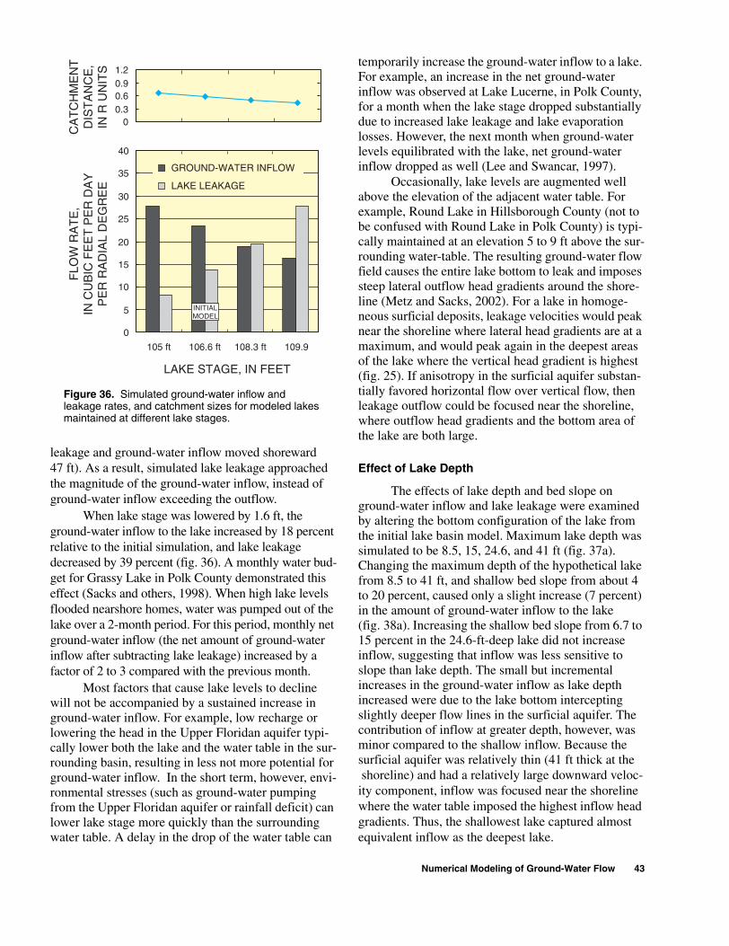
leakage and ground-water inflow moved shoreward 47 ft). As a result, simulated lake leakage approached the magnitude of the ground-water inflow, instead of ground-water inflow exceeding the outflow.
When lake stage was lowered by 1.6 ft, the ground-water inflow to the lake increased by 18 percent relative to the initial simulation, and lake leakage decreased by 39 percent (fig. 36). A monthly water bud-get for Grassy Lake in Polk County demonstrated this effect (Sacks and others, 1998). When high lake levels flooded nearshore homes, water was pumped out of the lake over a 2-month period. For this period, monthly net ground-water inflow (the net amount of ground-water inflow after subtracting lake leakage) increased by a factor of 2 to 3 compared with the previous month.
Most factors that cause lake levels to decline will not be accompanied by a sustained increase in ground-water inflow. For example, low recharge or lowering the head in the Upper Floridan aquifer typi-cally lower both the lake and the water table in the sur-rounding basin, resulting in less not more potential for ground-water inflow. In the short term, however, envi-ronmental stresses (such as ground-water pumping from the Upper Floridan aquifer or rainfall deficit) can lower lake stage more quickly than the surrounding water table. A delay in the drop of the water table can
temporarily increase the ground-water inflow to a lake. For example, an increase in the net ground-water inflow was observed at Lake Lucerne, in Polk County, for a month when the lake stage dropped substantially due to increased lake leakage and lake evaporation losses. However, the next month when ground-water levels equilibrated with the lake, net ground-water inflow dropped as well (Lee and Swancar, 1997).
Occasionally, lake levels are augmented well above the elevation of the adjacent water table. For example, Round Lake in Hillsborough County (not to be confused with Round Lake in Polk County) is typi-cally maintained at an elevation 5 to 9 ft above the sur-rounding water-table. The resulting ground-water flow field causes the entire lake bottom to leak and imposes steep lateral outflow head gradients around the shore-line (Metz and Sacks, 2002). For a lake in homoge-neous surficial deposits, leakage velocities would peak near the shoreline where lateral head gradients are at a maximum, and would peak again in the deepest areas of the lake where the vertical head gradient is highest (fig. 25). If anisotropy in the surficial aquifer substan-tially favored horizontal flow over vertical flow, then leakage outflow could be focused near the shoreline, where outflow head gradients and the bottom area of the lake are both large.
Effect of Lake Depth
The effects of lake depth and bed slope on ground-water inflow and lake leakage were examined by altering the bottom configuration of the lake from the initial lake basin model. Maximum lake depth was simulated to be 8.5, 15, 24.6, and 41 ft (fig. 37a). Changing the maximum depth of the hypothetical lake from 8.5 to 41 ft, and shallow bed slope from about 4 to 20 percent, caused only a slight increase (7 percent) in the amount of ground-water inflow to the lake (fig. 38a). Increasing the shallow bed slope from 6.7 to 15 percent in the 24.6-ft-deep lake did not increase inflow, suggesting that inflow was less sensitive to slope than lake depth. The small but incremental increases in the ground-water inflow as lake depth increased were due to the lake bottom intercepting slightly deeper flow lines in the surficial aquifer. The contribution of inflow at greater depth, however, was minor compared to the shallow inflow. Because the surficial aquifer was relatively thin (41 ft thick at the shoreline) and had a relatively large downward veloc-ity component, inflow was focused near the shoreline where the water table imposed the highest inflow head gradients. Thus, the shallowest lake captured almost equivalent inflow as the deepest lake.
0
5
10
15
20
25
30
35
40
105 ft 106.6 ft 108.3 ft 109.9
LAKE STAGE, IN FEET
GROUND-WATER INFLOW
LAKE LEAKAGE
00.30.60.91.2
CA
TC
HM
EN
TD
IST
AN
CE
,IN
R U
NIT
S
FLO
W R
AT
E,
IN C
UB
IC F
EE
T P
ER
DA
YP
ER
RA
DIA
L D
EG
RE
E
INITIALMODEL
Figure 36. Simulated ground-water inflow and leakage rates, and catchment sizes for modeled lakes maintained at different lake stages.
Numerical Modeling of Ground-Water Flow 43

15 PERCENT SLOPE
6.7 PERCENT SLOPE
APPROXIMATELY 4 PERCENT BED SLOPE
0 328 656 984 1,312 1,640 1,968 2,296 2,624
0 328 656 984 1,312 1,640 1,968 2,296 2,624
40
120
140
60
20
100
80
0
20 PERCENT SLOPE
DISTANCE FROM MODEL CENTERLINE, IN FEET
24.6 FEET
41 FEET 20 PERCENT BED SLOPE
6.7 PERCENT BED SLOPE
4 PERCENT BED SLOPE
3 PERCENT BED SLOPE
8.5 FEET
15 FEET
57.4 FEET
40
120
140
60
20
100
80
0
ELE
VA
TIO
N A
BO
VE
MO
DE
L O
RIG
IN, I
N F
EE
T
INTERMEDIATE CONFINING UNIT
INTERMEDIATE CONFINING UNIT
LAKEDEPTH
(A)
(B)
LAKEDEPTH
41 FEET
15 FEET
8.5 FEET
initial model
24.6 FEET
Figure 37. Different lake depths and surficial aquifer thicknesses used in model simulations. Surficial aquifer thickness near lake is: (A) 41 feet and (B) 57.4 feet.
44 Factors Affecting Ground-Water Exchange and Catchment Size for Florida Lakes in Mantled Karst Terrain
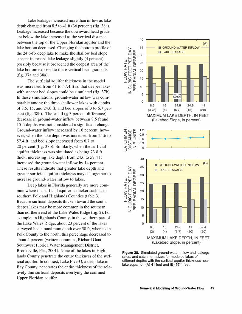
Lake leakage increased more than inflow as lake depth changed from 8.5 to 41 ft (36 percent) (fig. 38a). Leakage increased because the downward head gradi-ent below the lake increased as the vertical distance between the top of the Upper Floridan aquifer and the lake bottom decreased. Changing the bottom profile of the 24.6-ft- deep lake to make the shallow bed slope steeper increased lake leakage slightly (4 percent), possibly because it broadened the deepest area of the lake bottom exposed to these vertical head gradients (fig. 37a and 38a).
The surficial aquifer thickness in the model was increased from 41 to 57.4 ft so that deeper lakes with steeper bed slopes could be simulated (fig. 37b). In these simulations, ground-water inflow was com-parable among the three shallower lakes with depths of 8.5, 15, and 24.6 ft, and bed slopes of 3 to 6.7 per-cent (fig. 38b). The small (< 3 percent difference) decrease in ground-water inflow between 8.5 ft and 15 ft depths was not considered a significant change. Ground-water inflow increased by 16 percent, how-ever, when the lake depth was increased from 24.6 to 57.4 ft, and bed slope increased from 6.7 to 20 percent (fig. 38b). Similarly, when the surficial aquifer thickness was simulated as being 73.8 ft thick, increasing lake depth from 24.6 to 57.4 ft increased the ground-water inflow by 14 percent. These results indicate that greater lake depth and greater surficial aquifer thickness may act together to increase ground-water inflow to lakes.
Deep lakes in Florida generally are more com-mon where the surficial aquifer is thicker such as in southern Polk and Highlands Counties (table 3). Because surficial deposits thicken toward the south, deeper lakes may be more common in the southern than northern end of the Lake Wales Ridge (fig. 2). For example, in Highlands County, in the southern part of the Lake Wales Ridge, about 23 percent of the lakes surveyed had a maximum depth over 50 ft, whereas in Polk County to the north, this percentage decreased to about 4 percent (written commun., Richard Gant, Southwest Florida Water Management District, Brooksville, Fla., 2001). None of the lakes in High-lands County penetrate the entire thickness of the surf-icial aquifer. In contrast, Lake Five-O, a deep lake in Bay County, penetrates the entire thickness of the rela-tively thin surficial deposits overlying the confined Upper Floridan aquifer.
0
5
10
15
20
25
30
35
40
8.5 (3.75)
15(4)
24.6 (6.7)
24.6(15)
41 (20)
MAXIMUM LAKE DEPTH, IN FEET (Lakebed Slope, in percent)
GROUND-WATER INFLOW
LAKE LEAKAGE
(A)
0
5
10
15
20
25
30
35
40
8.5(3)
15 (4)
24.6 (6.7)
41 (20)
57.4 (20)
MAXIMUM LAKE DEPTH, IN FEET (Lakebed Slope, in percent)
GROUND-WATER INFLOW
LAKE LEAKAGE
(B)
00.30.60.91.2
CA
TC
HM
EN
TD
IST
AN
CE
,IN
R U
NIT
S
FLO
W R
AT
E,
IN C
UB
IC F
EE
T P
ER
DA
YP
ER
RA
DIA
L D
EG
RE
E
FLO
W R
AT
E,
IN C
UB
IC F
EE
T P
ER
DA
YP
ER
RA
DIA
L D
EG
RE
E
INITIALMODEL
Figure 38. Simulated ground-water inflow and leakage rates, and catchment sizes for modeled lakes of different depths with the surficial aquifer thickness near lake equal to: (A) 41 feet and (B) 57.4 feet.
Numerical Modeling of Ground-Water Flow 45

In model simulations, hydrogeologic factors that slow the movement of water to the Upper Floridan aquifer increase the saturated thickness of the surficial aquifer. For example, lowering the conductivity of the intermediate confining unit, raising the head in the Upper Floridan aquifer, decreasing Kh, or increasing the anisotropy in the surficial aquifer increases the sat-urated thickness of the surficial aquifer. Greater recharge also can raise the level of the surficial aquifer. These same factors, however, affect the vertical head gradient and flow lines within the surficial aquifer in different ways, changing the flow lines that are inter-cepted by the lake. Factors that promote lateral over vertical flow in the surficial aquifer can allow a deeper lake to intercept more ground-water inflow than a shallower lake. If most of the vertical head loss between a lake and the Upper Floridan aquifer occurs in the deeper surficial aquifer and through the confin-ing unit, then lateral flow can predominate in the shal-low surficial aquifer, enhancing ground-water inflow. If a substantial amount of vertical head loss occurs throughout the surficial aquifer, and flowlines in the surficial aquifer become more vertical, then deeper lakes may have little advantage over shallow lakes for intercepting lateral flow.
Transient Simulation Results
Four transient simulations were made to exam-ine the potential effects of transient recharge and basin topography on the magnitude and timing of ground-water inflow to lakes. In steady-state simulations, recharge boundary fluxes to the model are constant and the water table achieves the same equilibrium position irrespective of the hillside topography. In reality, rainfall on the basin is variable during days, seasons, and years, and the water table responds constantly to the recharge rate arriving from the unsaturated zone. Differences in hillside topography largely control the thickness of the unsaturated zone above the water table, given that other aspects of the hydrogeologic setting are comparable. This thickness, as well as the moisture status and unsaturated hydrau-lic properties of the soil, affect the time required for recharge to arrive at the water table. Because topogra-phy affects the timing and recharge rate to the water table, it also affects the transient water-table position, and thus ground-water flow.
One of the simulated hillsides was relatively low and level, and the unsaturated zone was thin (maxi-mum thickness 10 ft) (fig. 23). The other hillside was
steeper, reaching a higher elevation at the basin drain-age divide. The maximum unsaturated zone thickness in the steeper hillside models was about 49 ft (fig. 23). Transient simulations first were generated for each of the two hillsides. Then, the land surface nearby each lake was lowered to examine the effect of variable topography on the water-table configuration and inflow to the lake. The elevation of the hillside was altered most within a distance 0.5R onshore of the lake, in the area that most likely comprises much of the ground-water catchment.
The level hillside generated more ground-water inflow to the lake over the 5-month simulation period than the steeper hillside (table 6). The level hillside with the lowered nearshore region generated the most inflow: about 32.3 ft3/d/degree or about 8 percent more than either of the steep hillside basins.
For the level hillside model, more ground-water inflow was generated with the lowered nearshore region. Most of this additional inflow occurred during the rainy period, in the first third of the simulation (fig. 39). The inflow generated during the dry season was comparable but slightly less for the level hillside with the low nearshore region.
For the steep hillside, lowering the nearshore region generated slightly more ground-water inflow during the wet season compared with the unaltered steep basin, however, the increase was less than for the level basin. During the dry season, the lake received less inflow than it would have if the elevation of the nearshore region remained high. As a result, the steep basin with the lower hillside generated slightly less ground-water inflow over the total simulation period than the unaltered steep hillside.
Table 6. Simulated ground-water inflow to lakes adjacent to level and steep hillsides
Daily Average Ground-Water Inflow(cubic feet per day per radial degree)1
1Ground-water inflow computed in the radial model is divided by 360 degrees and reported here as flux per degree.
HillsideTotal
periodWet
seasonDry
season
Level 31.4 34.5 30.2
Level with low nearshore region 32.3 37.3 30.0
Steep 30.4 33.4 29.1
Steep with low nearshore region 30.0 34.6 28.1
46 Factors Affecting Ground-Water Exchange and Catchment Size for Florida Lakes in Mantled Karst Terrain

20
30
40
50
60
70
80
115 147 179 211 243 275
(B)
20
30
40
50
60
70
80
115 147 179 211 243 275
MODEL DAY
LEVEL BASIN WITH LOW NEAR-SHORE AREA
STEEP BASIN WITH LOWNEAR-SHORE AREA
(C)
20
30
40
50
60
70
80
115 147 179 211 243 275
LEVEL BASIN
LEVEL BASIN WITH LOWNEAR-SHORE AREA
GR
OU
ND
-WA
TE
R IN
FLO
W,
IN C
UB
IC F
EE
T P
ER
DA
YP
ER
RA
DIA
L D
EG
RE
E
GR
OU
ND
-WA
TE
R IN
FLO
W,
IN C
UB
IC F
EE
T P
ER
DA
YP
ER
RA
DIA
L D
EG
RE
E
GR
OU
ND
-WA
TE
R IN
FLO
W,
IN C
UB
IC F
EE
T P
ER
DA
YP
ER
RA
DIA
L D
EG
RE
E
(A)
STEEP BASIN
STEEP BASIN WITH LOWNEAR-SHORE AREA
Figure 39. Transient ground-water inflow to modeled lakes for basins with different unsaturated zone thicknesses.
Numerical Modeling of Ground-Water Flow 47

FACTORS AFFECTING GROUND-WATER EXCHANGE AND CATCHMENT SIZE
Ground-water flow modeling was used to examine the factors affecting ground-water inflow, catchment size, and lake leakage for lakes in mantled karst terrain. Changes to individual basin characteris-tics were simulated in the numerical modeling, how-ever, ground-water inflow to a given lake is affected by a combination of basin characteristics that act to increase or diminish catchment size. The variety of combinations can result in a wide range of ground-water inflow values in actual lakes (table 2). Modeling results, however, suggest that by defining lake basin characteristics, we can begin to infer whether the inflow potential for a given lake is low or high.
In some settings, hydrogeologic characteristics can have an additive effect increasing the potential for a lake to receive inflow. In other settings, the cumula-tive effect of these characteristics can greatly decrease the potential for ground-water inflow. For example, multiple basin characteristics tend to enlarge the catch-ment at Lake Five-O and increase the amount of ground-water inflow. The basin is large (7R maxi-mum), and the lake is deep (about 50 ft). Heads in the Upper Floridan aquifer showed little effects of pump-ing. The Kh of the surficial aquifer is high (about 60 ft/d), whereas the intermediate confining unit sur-rounding the lake is low (Kv about 0.0001 ft/d). As a result, the lake consistently receives inflow along its entire perimeter (Grubbs, 1995). Further, the soils in the basin are highly permeable, the topography is level, and the unsaturated zone throughout the basin is relatively thin (maximum thickness about 25 ft). Annual average rainfall in the Lake Five-O basin, in the panhandle of Florida, is higher than in the Central Highlands, which would increase the size of the catch-ment and the inflow contribution, due to transient recharge phenomena (fig.16).
The comparably large leakage losses from Lake Five-O could result from the presence of conductive material in the collapse feature beneath the lake (derived from the conductive surficial deposits), the depth of the lake, and the absence of an extensive sedi-ment lens.
In contrast to Lake Five-O, a combination of basin characteristics tend to diminish the size of the ground-water catchment at Lake Barco (Lee, 1996). The lake is shallow (about 20 ft deep), the Kh of the
surficial aquifer is relatively low (1-3 ft/d), and the intermediate confining unit surrounding the lake is leaky—2 to 3 orders of magnitude more conductive than at Lake Five-O. The topographic basin is large and steep toward the north (maximum distance 4R) where the catchment lies, but a subsidence feature located within the catchment reduces the ground-water inflow entering the lake. The southern side of the lake basin is smaller (0.7 R) and the water table is fre-quently lower than the lake in this area, resulting in lateral leakage along the southern shoreline.
Several basin characteristics slow leakage from Lake Barco. Heads in the Upper Floridan aquifer showed little evidence of pumping. The lake is rela-tively shallow (maximum depth about 20 ft) and has a thick sediment lens covering over two-thirds of the lake bottom. The combination of sediment and geo-logic material beneath Lake Barco was estimated to be 2 to 3 orders of magnitude less conductive (tighter) than at Lake Five-O. Surficial deposits at Lake Barco were less conductive compared to Lake Five-O, and this slowed the rate of both lateral and vertical leakage losses. Flow reversals due to transient recharge phe-nomena also slowed lake leakage. For example, for days to weeks after large rainfall events, the water table along the southern shoreline mounded above lake stage. The temporary flow reversal generated ground-water inflow and inhibited lateral lake leakage (Lee, 2000). At Lakes Five-O and Barco, the thickness of the surficial aquifer near the lakeshore was compara-ble (about 40 to 50 ft), and the vertical head difference between the lakes and the Upper Floridan aquifer was comparable (about 5 ft).
When taken as a group, the 14 lakes with ground-water inflow estimates provided indirect sup-port for two of the simulated basin characteristics con-trolling inflow: lake depth and topographic basin size. Lakes in table 2 fell roughly into two groups: lakes with high ground-water inflow > 100 in/yr, and lakes with low ground-water inflow < 50 in/yr. Lake George (54 in/yr) is grouped in the latter group. When Lake Hollingsworth is omitted, all of the high inflow lakes had maximum lake depths of 30 ft or more, and all had maximum basin dimensions that were > 3R. None of the lakes with shallower lake depths or smaller (maxi-mum) basin lengths were in the high ground-water inflow group.
These two traits alone did not ensure the higher amount of ground-water inflow from the catchment.
48 Factors Affecting Ground-Water Exchange and Catchment Size for Florida Lakes in Mantled Karst Terrain
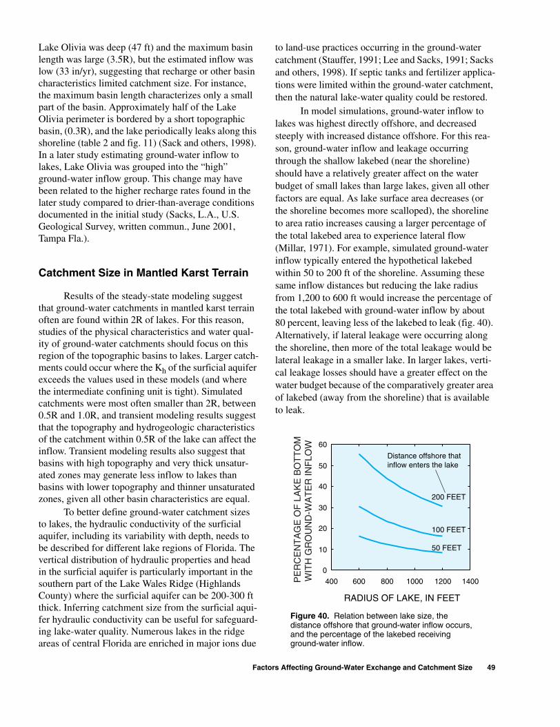
Lake Olivia was deep (47 ft) and the maximum basin length was large (3.5R), but the estimated inflow was low (33 in/yr), suggesting that recharge or other basin characteristics limited catchment size. For instance, the maximum basin length characterizes only a small part of the basin. Approximately half of the Lake Olivia perimeter is bordered by a short topographic basin, (0.3R), and the lake periodically leaks along this shoreline (table 2 and fig. 11) (Sack and others, 1998). In a later study estimating ground-water inflow to lakes, Lake Olivia was grouped into the “high” ground-water inflow group. This change may have been related to the higher recharge rates found in the later study compared to drier-than-average conditions documented in the initial study (Sacks, L.A., U.S. Geological Survey, written commun., June 2001, Tampa Fla.).
Catchment Size in Mantled Karst Terrain
Results of the steady-state modeling suggest that ground-water catchments in mantled karst terrain often are found within 2R of lakes. For this reason, studies of the physical characteristics and water qual-ity of ground-water catchments should focus on this region of the topographic basins to lakes. Larger catch-ments could occur where the Kh of the surficial aquifer exceeds the values used in these models (and where the intermediate confining unit is tight). Simulated catchments were most often smaller than 2R, between 0.5R and 1.0R, and transient modeling results suggest that the topography and hydrogeologic characteristics of the catchment within 0.5R of the lake can affect the inflow. Transient modeling results also suggest that basins with high topography and very thick unsatur-ated zones may generate less inflow to lakes than basins with lower topography and thinner unsaturated zones, given all other basin characteristics are equal.
To better define ground-water catchment sizes to lakes, the hydraulic conductivity of the surficial aquifer, including its variability with depth, needs to be described for different lake regions of Florida. The vertical distribution of hydraulic properties and head in the surficial aquifer is particularly important in the southern part of the Lake Wales Ridge (Highlands County) where the surficial aquifer can be 200-300 ft thick. Inferring catchment size from the surficial aqui-fer hydraulic conductivity can be useful for safeguard-ing lake-water quality. Numerous lakes in the ridge areas of central Florida are enriched in major ions due
to land-use practices occurring in the ground-water catchment (Stauffer, 1991; Lee and Sacks, 1991; Sacks and others, 1998). If septic tanks and fertilizer applica-tions were limited within the ground-water catchment, then the natural lake-water quality could be restored.
In model simulations, ground-water inflow to lakes was highest directly offshore, and decreased steeply with increased distance offshore. For this rea-son, ground-water inflow and leakage occurring through the shallow lakebed (near the shoreline) should have a relatively greater affect on the water budget of small lakes than large lakes, given all other factors are equal. As lake surface area decreases (or the shoreline becomes more scalloped), the shoreline to area ratio increases causing a larger percentage of the total lakebed area to experience lateral flow (Millar, 1971). For example, simulated ground-water inflow typically entered the hypothetical lakebed within 50 to 200 ft of the shoreline. Assuming these same inflow distances but reducing the lake radius from 1,200 to 600 ft would increase the percentage of the total lakebed with ground-water inflow by about 80 percent, leaving less of the lakebed to leak (fig. 40). Alternatively, if lateral leakage were occurring along the shoreline, then more of the total leakage would be lateral leakage in a smaller lake. In larger lakes, verti-cal leakage losses should have a greater effect on the water budget because of the comparatively greater area of lakebed (away from the shoreline) that is available to leak.
0
10
20
30
40
50
60
400 600 800 1000 1200 1400
RADIUS OF LAKE, IN FEET
50 FEET
100 FEET
200 FEET
Distance offshore that inflow enters the lake
PE
RC
EN
TA
GE
OF
LA
KE
BO
TT
OM
WIT
H G
RO
UN
D-W
AT
ER
INF
LOW
Figure 40. Relation between lake size, the distance offshore that ground-water inflow occurs, and the percentage of the lakebed receiving ground-water inflow.
Factors Affecting Ground-Water Exchange and Catchment Size 49
Hydrogeologic Controls on Ground-Water Exchange
The geology directly below lakes in mantled karst terrain is often distinctly different from that of the surrounding basin. In model simulations, the geo-logic framework underlying lakes, and its effect on downward leakage, acted largely independently of the geologic factors that regulated ground-water inflow to lakes. For example, simulated ground-water inflow was only moderately affected by changes in the sub-lake geology, unless the size of the sinkhole approached the size of the lake. Ground-water inflow responded mostly to factors affecting the water-table elevation in the surrounding basin, such as recharge rate or the degree of confinement in the basin. But these changes had little effect on the simulated lake leakage. The twofold nature of the karstic hydrogeo-logic setting does tend to decouple ground-water inflow processes from lake leakage in the short term. For example, short-term increases and decreases in ground-water inflow can have a relatively small effect on the concurrent lake leakage, assuming the leakage is occurring through the deeper lake bottom. (Short-term reversals of ground-water flow direction along the shoreline can greatly affect leakage.) Minimal short-term feedback between inflow and leakage has been described in transient simulations of saturated ground-water flow at Lakes Barco, Five-O and Starr, in which the short term changes in lake stage were rep-resented (Lee, 1996, Grubbs, 1995; Swancar and oth-ers, 2000). Over longer time periods, inflow and leakage tend toward equilibrium through the feedback mechanism provided by lake stage.
Unlike the two fold effect of the geologic set-tings, ground-water inflow and lake leakage responded in comparable measure to changes in the head in the Upper Floridan aquifer, changes in the imposed lake stage, and changes in the surficial aquifer hydraulic conductivity. Changes to the surficial aquifer hydraulic conductivity either increased or decreased both ground-water inflow and lake leakage. Changes in the head of the Upper Floridan aquifer, or the imposed lake stage, were the only basin characteristics that caused a direct decrease in the catchment size and ground-water inflow, and a commensurate increase in lake leakage. Conversely, a higher head in the Upper Floridan aquifer, or artificially lowered lake stage, resulted in an increase in ground-water inflow and decrease in lake leakage. Because of the opposing effect on inflow and leakage, changes in these two
head conditions have an appreciable effect on the net ground-water flow to the lake.
The constant lake stage used in the steady-state model tended to exaggerate the change in steady-state leakage or ground-water inflow instead of causing a decrease or increase in lake stage. Because the models oversimplified the representation of actual lakes, mod-eling results were considered qualitative. Simulated lakes were assumed to be circular with radial symme-try throughout the basin, with characteristics only partly represented in the 14 actual lake basins. Despite simplifications, modeling results provided insights into the factors controlling ground-water inflow to lakes from different types of lake basins.
In transient model simulations, differences in hillside topography caused spatially variable recharge to the water table of the four basins, even though iden-tical net precipitation rates were applied at land sur-face. The spatial differences in recharge below the four hillsides were due to the differences in the travel times through the unsaturated zones, caused by differences in the thickness and soil moisture content of the unsat-urated zones. In general, a thinner unsaturated zone and more rapid recharge to the water table adjacent to the lake tended to increase the percentage of the net precipitation that became ground-water inflow to the lake during the wet season. Within the catchment area, topography and its effect on temporal and spatial recharge may enhance ground-water inflow to some lakes relative to others.
A variety of basin characteristics affect the amount of annual ground-water inflow to lakes in the mantled karst terrain of Florida. Differences in the karstic hydrogeologic setting, head in the Upper Flori-dan aquifer, and topography cause some lakes to be hydraulically well connected to their ground-water catchments and others to be weakly linked to their potential catchments. As a result, the ground-water catchment size, which is directly related to the recharge rate and basin hydrogeologic characteristics, can vary widely.
Steady-state, finite-element ground-water flow modeling was used to simulate the effect of various basin characteristics on the ground-water inflow, lake leakage, and catchment size of hypothetical lakes. Realistic basin characteristics were derived from the basins of 14 lakes with available ground-water inflow estimates. Eleven of the lakes were located in Polk and
SUMMARY AND CONCLUSIONS
50 Factors Affecting Ground-Water Exchange and Catchment Size for Florida Lakes in Mantled Karst Terrain

Highlands Counties, the remaining three lakes were in Bay, Hillsborough and Putnam Counties. Physical and hydrogeologic characteristics such as annual average recharge rate, lake depth, basin size, and head in the Upper Floridan aquifer were altered in steady-state model simulations. Transient simulations using daily recharge were used to examine the effect of the unsat-urated zone thickness on ground-water inflow. Model results indicate:1. An increase in the following basin characteristics
increased the size of the simulated steady-state ground-water catchment, the magnitude of ground-water inflow, and the depth and distance over which inflow entered the lake: • Recharge rate to the surficial aquifer• Size of the topographic basin• (Horizontal) hydraulic conductivity of the surfi-
cial aquifer• Lake depth/bed slope• Potentiometric surface of the Upper Floridan
aquifer2. Ground-water inflow increased as the following
characteristics decreased:• Hydraulic conductivity of the intermediate con-
fining unit around the lake• Number of sinkholes in the basin surrounding
the lake • Vertical velocity in the surficial aquifer• Unsaturated zone thickness in the basin and near
the lakeshore• Lake stage
3. Lake leakage flowed vertically downward out of the deeper areas in all of the simulated lakes. Vertical leakage increased with increases in the following characteristics: • Permeability of the organic sediments• Size of the sinkhole feature in the sublake region• Lake depth• (Vertical) hydraulic conductivity of the surficial
aquifer• Lake stage
4. Vertical leakage increased with decreases in the fol-lowing basin characteristics:• Potentiometric surface of the Upper Floridan
aquifer• Size of the organic sediment lens
5. In addition to vertical leakage, lateral leakage also occurred near the shoreline for certain hydrogeo-logic conditions in the basin. Lateral lake leakage occurred where the water table sloped away from the lake, and these losses had the potential to exceed vertical leakage losses, especially for some small lakes. The potential for lateral leakage
increased with increases in the following character-istics:• Hydraulic conductivity of the intermediate con-
fining unit around the lake• Lake stage• Sinkholes peripheral to the lake• Size of the sublake collapse feature relative to
the lake area 6. Lateral leakage increased with a decrease in the fol-
lowing characteristics:• Potentiometric surface of the Upper Floridan
aquifer• Recharge
Actual lake basins show a combination of characteristics that tend to diminish or enlarge the size of the ground-water catchment, and diminish or enhance lake leakage. Only one hydrogeologic characteristic simulated, the surficial aquifer hydraulic conductivity, simultaneously increased (or decreased) both ground-water inflow and lake leakage. The two hydraulic boundary conditions most likely to be altered by human activities, lake stage and the potentiometric surface of the Upper Floridan aquifer, affected ground-water inflow and lake leakage in opposing ways. As a result, lowering heads in the Upper Floridan aquifer or augmenting lake stage affects lake levels by decreasing the ground-water inflow and catchment size, and increasing lake leakage. A third hydraulic boundary condition, recharge, mostly affected ground-water inflow but would eventually indirectly affect lake leakage by changing the head in the Upper Floridan aquifer. Transient simulations of lakes in different geologic settings would be required to determine the cumulative effect of short-term fluctuations in these boundary conditions.
Modeling hypothetical lake basins provides a qualitative way to examine the effect of basin characteristics on ground-water exchange with actual lakes. By identifying the suite of controlling factors, lakes can be categorized by their physical and hydrogeologic settings and by their potential to exchange either high or low amounts of ground-water inflow and leakage. Understanding the relation between ground-water catchments and lakes also is an essential step toward managing lake-water quality. Knowledge of how ground-water catchments are related to lakes can be used by resource managers to recommend setback distances for septic tank drain fields, agricultural land uses, and other land-use practices that contribute nutrients and major ions to lakes.
Summary and Conclusions 51
REFERENCES
Anderson, M.P., and Munter, J.A., 1981, Seasonal reversal of ground-water flow around lakes and the relevance to stagnation points and lake budgets: Water Resources Research, v. 17, p. 1139-1150.
Andrews, W.J., Oliveras, J.P., and Col-lins, J.J., 1990, Preliminary report on the hydrogeology of Lake Five-O and vicinity, Bay County, Florida: U.S. Geological Survey Water-Resources Investigations Report 90-4148, 1 sheet.
Barcelo, M.D., Slonena, D.L., Camp, S.C., and Watson, J.D., 1990, Ridge II: A hydrogeologic investi-gation of the Lake Wales Ridge: Southwest Florida Water Manage-ment District Report, 130 p.
Brooks, H.K., 1981, Guide to the physi-ographic divisions of Florida: Gainesville, Florida Cooperative Extension Service, Institute of Food and Agricultural Sciences, University of Florida, 11 p.
Buono, Anthony, and Rutledge, A.T., 1978, Configuration of the top of the Floridan aquifer, Southwest Florida Water Management Dis-trict and adjacent areas: U.S. Geo-logical Survey Water-Resources Investigations Open-File Report 78-34, 1 sheet.
Buono, Anthony, Spechler, R.M., Barr, G.L., Wolansky, R.M., 1979, Gen-eralized thickness of the confining bed overlying the Floridan aquifer, Southwest Floridan Water Man-agement District: U.S. Geological Survey Water-Resources Investi-gations Open-File Report 79-1171, 1 sheet.
Clark, W.E., Musgrove, R.H., Menke, C.G., and Cagle, J.W., Jr., 1963, Hydrology of Brooklyn Lake near Keystone Heights, Florida: Florida Geological Survey Report of Inves-tigations No. 33, 43 p.
Eilers, J.M., Landers, D.H., Brakke, D.F., 1988, Chemical and physical characteristics of lakes in the southeastern United States:
52 Factors Affecting Ground-Water Exc
Environmental Science and Tech-nology, v. 22, p. 172-177.
Evans, M.W., Snyder, S.W., Hine, A.C., 1994, High-resolution seismic expression of karst evolution within the Upper Floridan aquifer system: Crooked Lake, Polk County, Florida: Journal of Sedi-mentary Research, v. 64, p. 232-244.
Geraghty and Miller, Inc., 1980, High-lands ridge hydrologic investiga-tion, Part 1: Final Report, and Part 2: Aquifer testing program: Pre-pared for the Peace River Basin Board of the Southwest Florida Water Management District, Sep-tember 1980, 135 p.
Griffith, G.E., Canfield, D.E., Hors-burgh, C.A., Omernik, J.M., 1997, Lake regions of Florida: Corvallis, Oregon, U.S. Environmental Pro-tection Agency, National Health and Environmental Effects Research Laboratory, EPA/R-97/127, 89 p.
Grubbs, J.W., 1995, Evaluations of ground-water flow and hydrologic budget for Lake Five-O, a seepage lake in northwestern Florida: Water-Resources Investigations Report 94-4145, 42 p.
Kindinger, J.L., Davis, J.B., and Flocks, J.G., 1994, High-resolution single-channel seismic reflection surveys of Orange Lake and other selected sites of north-central Florida: U.S. Geological Survey Open-File Report 94-616, 48 p.
Knowles, Leel, Jr., 1996, Estimation of evapotranspiration in the Rainbow Springs and Silver Springs basins in north-central Florida: U.S. Geological Survey Water-Resources Investigations Report 96-4024, 37 p.
Lee, T.M., 1996, Hydrogeologic con-trols on the groundwater interac-tions with an acidic lake in karst terrain, Lake Barco, Florida: Water Resources Research, v. 32, no. 4, p. 831-844.
———2000, Effects of nearshore recharge on groundwater interac-tions with a lake in mantled karst
hange and Catchment Size for Florida Lakes
terrain: Water Resources Research, v. 36, p. 2167-2182.
Lee, T.M., Adams, D.B., Tihansky, A.B., and Swancar, Amy, 1991, Methods, instrumentation, and preliminary evaluation of data for the hydrologic budget assessment of Lake Lucerne, Polk County, Florida: U.S. Geological Survey Water-Resources Investigations Report 90-4111, 42 p.
Lee, T.M., and Sacks, L.A., 1991, Determining ground-water inflow sources to a Florida seepage lake using a geochemical tracer approach, EOS, Transactions, American Geophysical Union, v. 72, no. 144, p. 188.
Lee, T.M., and Swancar, Amy, 1997, Influence of evaporation, ground water, and uncertainty in the hydro-logic budget of Lake Lucerne, a seepage lake in Polk County, Flor-ida: U.S. Geological Survey Water-Supply Paper 2439, 61 p.
Metz, P.A., and Sacks, L.A., 2002, Comparison of the hydrogeology and water quality of a ground-water augmented lake with two non-augmented lakes in northwest Hillsborough County Florida: U.S. Geological Survey Water-Resources Investigations Report 02-4032, 74 p.
Millar, J.B., 1971, Shoreline-area ratio as a factor in rate of water loss from small sloughs, Journal of Hydrology, v. 14, p. 259-284.
Motz, L.H., 1998, Vertical leakage and vertically-averaged vertical con-ductance for karst lakes in Florida: Water Resources Research, v. 34, p. 159-167.
National Oceanic and Atmospheric Administration, 1996, Climatolog-ical data annual summary, Flor-ida: Asheville, N.C., U.S. Department of Commerce, v. 100, no. 13.
Nield, S.P., Townley, L.R., Barr, A.D., 1994, A framework for quantita-tive analysis of surface water-ground water interaction: Flow geometry in a vertical section:
in Mantled Karst Terrain

Water Resources Research, v. 30, p. 2461-2475.
Pollman, C.D., Lee, T.M., Andrews, W.J., Sacks, L.A., Gherini, S.A., and Munson, R.K., 1991, Prelimi-nary analysis of the hydrologic and geochemical controls on acid-neu-tralizing capacity in two acidic seepage lakes in Florida: Water Resources Research, v. 27, p. 2321-2335.
Sacks, L.A., Lee, T.M., and Tihansky, A.B., 1992, Hydrogeologic setting and preliminary data analysis for the hydrologic-budget assessment of Lake Barco, an acidic seepage lake in Putnam County, Florida: U.S. Geological Survey Water-Resources Investigations Report 91-4180, 28 p.
Sacks, L.A., Swancar, Amy, Lee, T.M., 1998, Estimating ground-water exchange with lakes using water-budget and chemical mass-balance approaches for ten lakes in ridge areas of Polk and Highlands Coun-ties, Florida: U.S. Geological Sur-vey Water-Resources Investigations Report 98-4133, 52 p.
Salvucci, G.D., and Entekhabi, Dara, 1995, Hillslope and climatic con-trols on hydrologic fluxes: Water Resources Research, 31, p. 1725-1739.
Schiffer, D.M., 1998, Hydrology of central Florida lakes – a primer: U.S. Geological Survey Circular 1137, 38 p.
Šimuºnek, J., Sejna, M., and van Genu-chten, M. Th., 1996, HYDRUS-2D Simulating water flow and solute transport in two-dimensional vari-ably saturated media: Golden, Col-orado, International Ground Water Modeling Center, Colorado School of Mines, IGWMC-TPS 53,Ver-sion 1.0, January.
Šimuºnek, J., Vogel, T., and van Genu-chten, M. Th., 1992, The SWMS-2D code for simulating water flow and solute transport in two-dimen-sional variably-saturated media: Riverside, California, U.S. Salinity Laboratory, U.S. Department of Agriculture, Agricultural Research
Station, Version 1.1, Research Report No. 126, 169 p.
Stauffer, R.E., 1991, Effects of citrus agriculture on ridge lakes in cen-tral Florida: Water, Air, and Soil Pollution, v. 59, p. 125-144.
Stewart, H.G., Jr., 1966, Ground-water resources of Polk County: Florida Geological Survey Report of Investigations no. 44, 170 p.
Subsurface Detection Investigations, Inc., 1992, High resolution seismic reflection profiling in selected lakes in the St. Johns River Water Management District: Palatka, Florida, St. Johns River Water Management District Special Pub-lication SJ92-SP13, April.
Sumner, D.M., 1996, Evapotranspira-tion from an area of successional vegetation in a deforested area of the Lake Wales Ridge, Florida: U.S. Geological Survey Water-Resources Investigations Report 96-4244, 37 p.
Swancar, Amy, Lee, T.M., and O’Hare, T.M., 2000, Hydrogeologic set-ting, water-budget, and prelimi-nary analysis of ground-water exchange at Lake Starr, a seepage lake in Polk County, Florida: U.S. Geological Survey Water-Resources Investigations Report 00-4030, 66 p.
Tihansky, A.B., 1999, Sinkholes, west-central Florida: A link between surface water and ground water, in Galloway, Devin, Jones, D.R., and Ingebritsen, S.E., Land subsid-ence in the United States: U.S. Geological Survey Circular 1182, p. 121-140.
Tihansky, A.B., Arthur, J.D., and DeW-itt, D.W., 1996, Sublake geologic structure from high-resolution seismic-reflection data from four sinkhole lakes in the Lake Wales Ridge, Central Florida: U.S. Geo-logical Survey Open-File Report 96-224, 72 p.
Tihansky, A.B., and Sacks, L.A., 1997, Evaluation of nitrate sources using nitrogen isotrope techniques in shallow ground water within selected lake basins in the Central
T
T
V
W
W
—
—
W
Y
Lakes District, Polk and Highlands Counties, Florida: U.S. Geologi-cal Survey Water-Resources Inves-tigations Report 97-4207, 28 p.
ownley, L.R., and Davidson, M.R., 1988, Definition of a capture zone for shallow water table lakes, Jour-nal of Hydrology, v. 104, p. 53-76.
ownley, L.R., and Trefry, M.G., 2000, Surface water-ground water inter-action near shallow circular lakes: Flow geometry in three dimen-sions: Water Resources Research, v. 36, p. 935-949.
an Genuchten, M.T., Leij, F.J., and Yates, S.R., 1991, The RETC code for quantifying the hydraulic func-tions of unsaturated soils: Wash-ington, D.C., U.S. Environmental Protection Agency Report EPA/600/2-91/065, 85 p.
hite, W.A., 1970, The geomorphol-ogy of the Florida Peninsula: Flor-ida Geological Survey Bulletin 51, 164 p.
inter, T.C., 1976, Numerical simula-tion analysis of the interaction of lakes and ground water: U.S. Geo-logical Survey Professional Paper 1001, 45 p.
——Winter, T.C., 1978, Numerical simulation of steady state three-dimensional ground water flow near lakes: Water Resources Research v. 14, p. 245-254.
—— Winter, T.C., 1983, The interac-tion of lakes with variably-satu-rated porous media: Water Resources Research, v. 19, p. 1203-1218.
inter, T.C., and Pfannkuch, H.O., 1984, Effect of anisotropy and ground water system geometry on seepage through lakebeds, 2: Numerical simulation analysis, Journal of Hydrology, v. 75, p. 239-253.
obbi, D.K., 1996, Analysis and simu-lation of ground-water flow in Lake Wales Ridge and adjacent areas of central Florida: U.S. Geo-logical Survey Water-Resources Investigations Report 94-4256, 82 p.
References 53

54 Factors Affecting Ground-Water Exchange and Catchment Size for Florida Lakes in Mantled Karst Terrain