fan coil unit - climaproyectos s.a. de...
TRANSCRIPT

42CEFan Coil Unit

ContentsModel number Nomenclature/Air Flow
Features
Technical Parameter
Dimension
Fan Performance
42CE Fan Coil Unit
1
2
4
7
11
12
Carrier ChinaHeadquartered in Farmington, Connecticut, USA, Carrier Corporation is the world's largest provider of heating, air conditioning and refrigeration solutions, with operations in more than 170 countries including China.
Ever since Dr. Willis Carrier, founder of Carrier Corporation, invented modern air conditioning in 1902, Carrier has stayed at the forefront of the air-conditioning industry for more than 100 years. Regarded as the leader and expert in air conditioning, Carrier has several thousand patents in the air-conditioning industry and eleven lead design centers worldwide, including one in China.
Carrier's products are manufactured at numerous facilities on six continents. The company has approximately 41,000 employees around the world. In 2008, Carrier's revenues were US$14.9 billion, leading the Heating, Ventilation, Air-conditioning and Refrigeration (HVACR) industry.
Carrier set up its first joint venture in Shanghai in 1987. Now Carrier has more than 2,200 employees. Carrier products are distributed in China through a network of more than 40 sales and service offices.
1
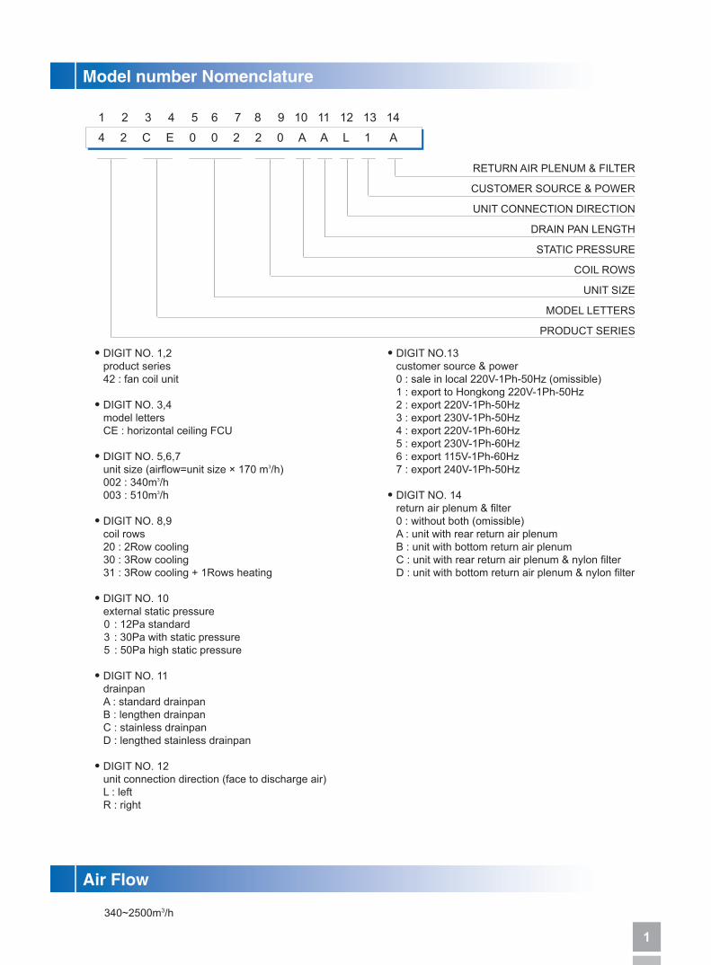
Model number Nomenclature
4 2 C E 0 0 2 2 0 A A L 1 A
RETURN AIR PLENUM & FILTER
CUSTOMER SOURCE & POWER
UNIT CONNECTION DIRECTION
DRAIN PAN LENGTH
STATIC PRESSURE
COIL ROWS
UNIT SIZE
MODEL LETTERS
PRODUCT SERIES
Air Flow
● DIGIT NO. 1,2 product series 42 : fan coil unit
● DIGIT NO. 3,4 model letters CE : horizontal ceiling FCU
● DIGIT NO. 5,6,7 unit size (airflow=unit size × 170 m3/h) 002 : 340m3/h 003 : 510m3/h
● DIGIT NO. 8,9 coil rows 20 : 2Row cooling 30 : 3Row cooling 31 : 3Row cooling + 1Rows heating
● DIGIT NO. 10 external static pressure 0 : 12Pa standard 3 : 30Pa with static pressure 5 : 50Pa high static pressure
● DIGIT NO. 11 drainpan A : standard drainpan B : lengthen drainpan C : stainless drainpan D : lengthed stainless drainpan
● DIGIT NO. 12 unit connection direction (face to discharge air) L : left R : right
340~2500m3/h
1 2 3 4 5 6 7 8 9 10 11 12 13 14
● DIGIT NO.13 customer source & power 0 : sale in local 220V-1Ph-50Hz (omissible) 1 : export to Hongkong 220V-1Ph-50Hz 2 : export 220V-1Ph-50Hz 3 : export 230V-1Ph-50Hz 4 : export 220V-1Ph-60Hz 5 : export 230V-1Ph-60Hz 6 : export 115V-1Ph-60Hz 7 : export 240V-1Ph-50Hz
● DIGIT NO. 14 return air plenum & filter 0 : without both (omissible) A : unit with rear return air plenum B : unit with bottom return air plenum C : unit with rear return air plenum & nylon filter D : unit with bottom return air plenum & nylon filter

2
42CE Fan Coil Units are the new energy saving products improved with advanced technology by Carrier. The units have advanced technology of low noise fan, air condition manufacture process and the last lanced sine wave fin. 42CE is developed to be an ultra-tranquil, high efficiency, convenient using and compact configuration product.
Ultra-tranquilThe units use the wide wheel of latest design and low speed forward-curved blades, which are most suitable for the motor. Addition with good insulated noise eliminated material, unit noise is 2~5dB(A) lower than the same type unit.
High efficiencyAluminum lanced sine wave fin coils with copper tubing assure highly efficient heat transfer between primary and secondary coil surfaces.
Ultra thinThe unit height is only 230mm so that they can save installation space and meet the requirement of all kinds of situations.
Features

3
Agile selection
Considering of the specialties and limit of installation, Carrier offer different drain pan to the consumer.● Standard drain pan-reduce the installation space, especially to the narrow installation space.● Lengthened drain pan-well collect possible sweating from field installed valves.● External drain pan-350mm length can be selected to meet the requirement of all kind of condition.
Beside the characteristic above, the units have moredevelopment below
● Change the terminal from close to open structure and the wiring of motor to metal tube to assure more safety and reliability.● The latest noise eliminated fiberglass insulation can assure not only the good appearance and perfect performance but also well-insulated performance measuring up the international standard under the testing of most abominable sweat condition.● The round wheel of latest design can apply high temperature situation reliably.● The drain pan and insulation are mould holistically to make the process more easy and better as well as prevent the leak when welding the drain pan. NOTE: Distinguish the direction of right or left by facing to the air outlet.
Accessories
3-way valve
2-way valve Thermostat
Remote Controller

4
Technical Parameter
TECHNICAL DATA (2R COIL)
HIGH
MED
LOW
Performance
Air Volume m3/h
Water Flow l/min
Water Drop KPa
Power InputW
12 Pa
30 Pa
50 Pa
12 Pa
30 Pa
50 Pa
Noise dB(A)
Type
Type
Row
Working Pressure
In-Out
Condensing Drain
Fan
Motor
Coil
CONNS
Net Weight Kg
Accessories
Cooling Capacity W
Heating Capacity W
Model
Centrifugal, forward-curved Blades
Permanent Split Capacitor
2
1.6 MPa
3/4” FPT
3/4” MPT
Thermostat,Motorized Valve, Return Air Plenum
Note: 1. The data is the performance in high speed with relevant static pressure. 2. Cooling Conditions: Entering Water 7℃,Temperature Rise 5℃, Entering Air Temperature 27℃DB,19.5℃WB. Heating Conditions: Entering Water 60℃, Air 21℃DB, the same water flow as the cooling conditions. 3. The noise is tested in the anechoic test room, measured with a fine audiometer located 1 meter away from the unit front panel and the unit bottom panel.
002 003 004 005 006 008
340 530 700 880 1020 1430
270 420 560 700 810 1140
200 310 420 520 610 850
1900 2820 3640 4500 5400 7200
3100 4400 5820 6900 8400 11160
32 46 56 75 94 134
40 54 72 87 102 155
46 65 84 98 112 174
36 38 41 43 45 46
40 41 44 46 47 48
42 44 46 47 49 50
6.3 9.4 12.1 15 18 24
20 28 26 30 34 38
12.7 14.2 16.1 17.4 18.5 25.8

5
Technical Parameter
TECHNICAL DATA (3R COIL)
HIGH
MED
LOW
Performance
Air Volume m3/h
Water Flow l/min
Water Drop KPa
Power InputW
12 Pa
30 Pa
50 Pa
12 Pa
30 Pa
50 Pa
Noise dB(A)
Type
Type
Row
Working Pressure
In-Out
Condensing Drain
Fan
Motor
Coil
CONNS
Net Weight Kg
Accessories
Cooling Capacity W
Heating Capacity W
Model
Note: 1. The data is the performance in high speed with relevant static pressure. 2. Cooling Conditions: Entering Water 7℃,Temperature Rise 5℃, Entering Air Temperature 27℃DB,19.5℃WB. Heating Conditions: Entering Water 60℃, Air 21℃DB, the same water flow as the cooling conditions. 3. The noise is tested in the anechoic test room, measured with a fine audiometer located 1 meter away from the unit front panel and the unit bottom panel.
002 003 004 005 006 008 010 012 014
340 510 680 850 1020 1360 1700 2040 2380
265 405 535 680 790 1060 1360 1595 1904
195 305 405 510 585 790 1020 1180 1428
2300 3200 4250 5000 5900 8000 9200 11050 13000
3600 5100 6450 7870 9300 12100 14500 17200 20500
32 46 58 76 91 130 150 180 208
41 52 65 87 106 150 172 210 250
48 63 82 100 118 174 205 236 290
37 39 41 43 45 46 48 49 50
39 41 43 46 47 47.5 49 51 52
41 43 45 47 49 50 51 53 52
6.6 9 12.3 13.8 17 23.5 27 33 37
14 29 20 24 35 35 40 40 47
Centrifugal, forward-curved Blades
Permanent Split Capacitor
3
1.6 MPa
3/4”FPT
3/4” MPT
14 15.6 17.7 19.1 20.5 28.3 31 35.3 41.5
Thermostat, Motorized Valve, Return Air Plenum

6
Technical Parameter
TECHNICAL DATA (3+1R COIL)
Note: 1. The data is the performance in high speed with relevant static pressure. 2. Cooling Conditions: Entering Water 7℃,Temperature Rise 5℃, Entering Air Temperature 27℃DB,19.5℃WB. Heating Conditions: Entering Water 60℃, Entering/leaving temperature difference is 10℃,enter air temperature 21℃DB. 3. The noise is tested in the anechoic test room, measured with a fine audiometer located 1 meter away from the unit front panel and the unit bottom panel.
Performance Model
Air Volume m3/h
12Pa
30Pa
HIGH
MED
LOW
Cooling W 12Pa/30Pa
Heating W 12Pa/30Pa
Power InputW
12 Pa
30 Pa
Noise dB(A)
12 Pa
30 Pa
Water Flow l/min
12Pa Heating
30Pa Heating
Water Drop KPa
12Pa Heating
30Pa Heating
Fan Type
Motor Type
CoilRow
Working Pressure
CONNSIn-Out
Condensing Drain
Net Weight Kg
Accessories
002 003 004 005 006 008
340 510 680 850 1020 1360
265 405 535 680 790 1060
195 305 405 510 585 790
2208 3080 4080 4800 5664 7680
2276 2855 3382 4188 4968 6433
32 46 58 76 91 130
41 52 65 87 106 150
37 39 41 43 45 46
39 41 43 46 47 47.5
6.3 8.6 11.8 13.2 16.3 22.6
3.3 4.2 4.9 6.1 7.3 9.4
13 28 19 24 34 34
9 11 14 17 20 24
Centrifugal, forward-curved Blades
Permanent Split Capacitor
3+1
1.6 MPa
3/4“FPT
3/4” MPT
15 16.6 18.8 20.2 21.7 29.5
Thermostat,Motorized Valve, Return Air Plenum

7
Dimensions(2Row)
Note: 1. With Rear/Bottom air return plenum 2. Easily connect with Rear/Bottom air return plenum in the jobsite 3. No filter in the air plenum, please install the filter at the return air duct 4. The dimension of return air inlet for rear air return plenum is the same as that of the bottom air return plenum.
Fan Coil Unit
42CE Return Air Plenum
Model
002
003
004
005
006
008
010
012
014
Dimension
A B C D E F H J K M N
690
770
890
970
1170
1410
1530
1770
2010
770
890
970
1090
1410
1530
1770
2010
2250
550
630
750
830
1030
1270
1390
1630
1870
520
600
720
800
1000
1240
1360
1600
1840
35
75
75
55
95
95
95
95
95
480
480
600
720
840
1080
1200
1440
1680
550
630
750
830
1030
1270
1390
1630
1870
75
115
75
115
115
35
95
115
135
400
400
600
600
800
1200
1200
1400
1600
10
12
14
16
18
26
28
32
36
6
6
6
8
8
10
10
12
14
Part Number
42CE402900
42CE403900
42CE404900
42CE405900
42CE406900A
42CE408900
42CE410900
42CE412900
42CE414900
Dimension
Note: B is the dimension of lengthen drain pan
A B C D E F Return Air Inlet(H×W) Used In
554 47 2 400 494 520 181×494 42CE002
634 87 2 400 574 600 181×574 42CE003
754 47 3 600 694 720 181×694 42CE004
834 87 3 600 774 800 181×774 42CE005
1034 87 4 800 974 1000 181×974 42CE006
1274 107 5 1000 1214 1240 181×1214 42CE008
1394 67 6 1200 1334 1360 181×1334 42CE010
1634 87 7 1400 1574 1600 181×1574 42CE012
1874 107 8 1600 1814 1840 181×1814 42CE014

8
Dimensions(2Row)
Fan Coil Unit
BottomReturn Air
RearReturn Air
Unit
30
273 18
1
566
90
256
29
Return Air Flanges
F
C 200=D
E
301
14
3
13
164
4-12 22mm Hanger Slots (4)
B
42CE Return Air Plenum

9
Dimensions(3Row)
Note: 1. With Rear/Bottom air return plenum 2. Easily connect with Rear/Bottom air return plenum in the jobsite 3. No filter in the air plenum, please install the filter at the return air duct 4. The dimension of return air inlet for rear air return plenum is the same as that of the bottom air return plenum.
Fan Coil Unit
42CE Return Air Plenum
Model
002
003
004
005
006
008
010
012
014
Dimension
A B C D E F H J K M N
690
770
890
970
1090
1410
1530
1770
2010
770
890
970
1090
1410
1530
1770
2010
2250
550
630
750
830
950
1270
1390
1630
1870
520
600
720
800
920
1240
1360
1600
1840
35
75
75
55
55
95
95
95
95
480
480
600
720
840
1080
1200
1440
1680
550
630
750
830
950
1270
1390
1630
1870
72
112
72
112
72
32
92
112
132
400
400
600
600
800
1200
1200
1400
1600
10
12
14
16
18
26
28
32
36
6
6
6
8
8
10
10
12
14
Part Number
42CE402900
42CE403900
42CE404900
42CE405900
42CE406900
42CE408900
42CE410900
42CE412900
42CE414900
Dimension
Note: B is the dimension of lengthen drain pan
A B C D E F Return Air Inlet(H×W) Used In
554 47 2 400 494 520 181×494 42CE002
634 87 2 400 574 600 181×574 42CE003
754 47 3 600 694 720 181×694 42CE004
834 87 3 600 774 800 181×774 42CE005
954 47 4 800 894 920 181×894 42CE006
1274 107 5 1000 1214 1240 181×1214 42CE008
1394 67 6 1200 1334 1360 181×1334 42CE010
1634 87 7 1400 1574 1600 181×1574 42CE012
1874 107 8 1600 1814 1840 181×1814 42CE014

10
Dimensions(3Row)
Fan Coil Unit
FCU with cooling + heating coil
42CE Return Air Plenum
A(B)32
119
15
3/4"MPT Drain CONN.
H
KJ
FC
E
124
15
142
152
68 10
1
65
41
164
Motor
12mm 22mm Hanger Slots (4)
M- 3.2
N- 3.2 D
4- 5.1
Fan
3/4" FPT R.W CONN.
3/4" FPT S.W CONN.
8- 3.2
143
Nameplate Terminal box(Opposite)
466
283
254 19
118
51
30
59
220
BottomReturn Air
RearReturn Air
Unit
30
273 18
1
566
90
256
29
Return Air Flanges
F
C 200=D
E
301
14
3
13
164
4-12 22mm Hanger Slots (4)
B
A(B)32
119
15
1185
2
3/4" FPT S.W CONN. (Hot)
3/4" FPT R.W CONN. (Cold)
466
283
110
143
66
254 19
3/4" FPT S.W CONN. (Cold)
Nameplate
220
3/4" FPT R.W CONN. (Hot)
H
KJ
C
124
10
16
5
41
16
4
12mm 22mm Hanger Slots (4)3/4"MPT Drain CONN.
D
FE
M- 3.2
4- 5.1
15
142
68
N- 3.2
MotorFan
8- 3.2
30
59

11
Fan Performance
Standard Unit Standard Unit
With Static Pressure Unit With Static Pressure Unit
Air Flow m3/min)
Air Flow m3/min)
Air Flow m3/min)
Air Flow m3/min)
Ext
erna
l Sta
tic P
ress
ure(
Pa)
Ext
erna
l Sta
tic P
ress
ure(
Pa)
Ext
erna
l Sta
tic P
ress
ure(
Pa)
Ext
erna
l Sta
tic P
ress
ure(
Pa)
Ext
erna
l Sta
tic P
ress
ure(
Pa)
Ext
erna
l Sta
tic P
ress
ure(
Pa)
Air Flow m3/min)Air Flow m3/min)
High Static Pressure Unit High Static Pressure Unit
42CE002200~42CE008200
42CE002203~008203
42CE002205~42CE008205
42CE002303~42CE014303/42CE002313~42CE008313
42CE002305~42CE014305/42CE002315~42CE008315
42CE002300~42CE014300/42CE002310~42CE008310
3/(3+1)R2R
2R
2R
3/(3+1)R
3/(3+1)R

12
42CE Fan Coil Unit
Cap CapacitorFM Fan MotorO OffSS SwitchTB Terminal Block
Factory WiringField Wiring
O L M HRedBlueWhiteYellow
002 003 004 005 006 008 010 012 014
32 46 56 75 94 134 - - -
40 54 72 87 102 155 - - -
46 65 84 98 112 174 - - -
32 46 58 76 91 130 150 180 208
41 52 65 87 106 150 172 210 250
48 63 82 100 118 174 205 236 290
0.15 0.21 0.25 0.34 0.43 0.61 - - -
0.18 0.25 0.33 0.40 0.46 0.70 - - -
0.21 0.30 0.38 0.45 0.51 0.79 - - -
0.15 0.22 0.26 0.35 0.41 0.59 0.68 0.82 0.95
0.19 0.24 0.30 0.40 0.48 0.68 0.78 0.96 1.14
0.22 0.29 0.37 0.46 0.54 0.54 0.93 1.07 1.32
2row 12Pa
2row 30Pa
2row 50Pa
3row 12Pa
3row 30Pa
3row 50Pa
2row 12Pa
2row 30Pa
2row 50Pa
3row 12Pa
3row 30Pa
3row 50Pa
PowerInput(W)
Current(A)
TypePower: 220V-1Ph-50Hz

T-42CE-1009-04(E)
Carrier Corporation identified six specific areas of concentration that directly impact howwe, as a world manufacturer, balance our curtomer' needs for comfort with the environment'sneeds for responsible consumption.
Welcome to Carrier Websitew w w . c a r r i e r . c o m . c n
The Manufacturer reserves the right to change any produt specifications without notices All Rights Reserved Carrier