fast bal i/ii book · reference manual fast bal i/ii quick start reference csi part # 97048pb rev....
TRANSCRIPT

Reference Manual
FAST Bal I/II
Quick Start Reference
CSI Part # 97048PB Rev. 4
FAST Bal I/II Book Page i Wednesday, November 17, 1999 3:26 PM

ii
Copyright
©
1999 by Computational Systems, Incorporated.All rights reserved.
No part of this publication may be reproduced, trans-mitted, transcribed, stored in a retrieval system, or translated into any language in any form by any means without the written permission of Computational Systems, Incorporated (CSI).
Disclaimer
This manual is provided for informational purposes. C
OMPUTATIONAL
S
YSTEMS
, I
NCORPORATED
M
AKES
N
O
W
ARRANTY
O
F
A
NY
K
IND
W
ITH
R
EGARD
T
O
T
HIS
M
ATERIAL
, I
NCLUDING
, B
UT
N
OT
L
IMITED
T
O
, T
HE
I
MPLIED
W
ARRANTIES
O
F
M
ERCHANTABILITY
A
ND
F
ITNESS
F
OR
A P
ARTICULAR
P
URPOSE
. Computational Systems, Incorporated shall not be liable for errors, omissions, or inconsistencies that may be contained herein or for incidental or consequential damages in connection with the furnishing, performance, or use of this material. Information in this document is subject to change without notice and does not represent a commitment on the part of Computational Systems, Incorporated. The information in this manual is not all-inclusive and cannot cover all unique situations.
Product Support
Should you have any comments on this documenta-tion or questions concerning the Agreement on the following pages, please contact CSI’s Product Support Department.
Address:
Computational Systems, Incorporated835 Innovation DriveKnoxville, TN 37932 USA
Phone:
United States and Canada: 865-671-4274Spanish-speaking customers: 865-675-2377
FAX:
865-675-4893
Internet E-mail:
United States and Canada: [email protected]: [email protected]
Worldwide Web:
http://www.compsys.com
StarTrend Reference Manual
This document was written, illustrated, and produced by CSI’s Engineering Publications Group on Power Macintosh
™
workstations using Adobe
™
FrameMaker
®
, Adobe PhotoShop
®
, and Macromedia
®
FreeHand
™
. Printed copies are produced using the Xerox
™
DocuTech
™
publishing system.
Trademarks and Servicemarks
AccuTrend; Changing the way the world performs maintenance, and CSI logo; CSI
RBM
‚(Mexico); Doctor Know; Infranalysis; InfraRoute; Levels of Awareness Training; M&D; MachineGuard; MachineView; MasterNet; MotorView; Nspectr; O&M Workstation; OilView (Japan); RBMware; Reliability-Based Mainte-nance, and logo; RollView; StarterTrend; STATUS Technologies; TrendSetter; Tribology Minilab; UltrasSpec; and WAVEPAK are registered trademarks of Computational Systems, Incorporated.
CSI (China, Japan, Venezuela, Australia); CSI
RBM
(Vene-zuela); Status Condition Monitor; PeakVue; RBMview; RBMware (Australia, China, Japan); RBMwizard; Reli-ability-Based Maintenance (Venezuela); SonicScan; SonicView; SST; STATUS RF SmartSensor; STATUS RF Transceiver; VersaBal; VibPro; VibView; and Weld-watch are pending trademarks of Computational Systems, Incorporated.
Lubricant Profile and Trivector are registered service-marks of Computational Systems, Incorporated.
RBM; RBMware (China); Reliability-Based Mainte-nance (Venezuela); and STATUS Technologies and design are pending servicemarks of Computational Systems, Incorporated.
Adobe is a trademark and FrameMaker and PhotoShop are registered trademarks of Adobe Systems, Inc. Power Macintosh is a trademark of Apple Computer, Inc. Macromedia is a registered trademark and Free-Hand is a trademark of Macromedia, Inc. Xerox and DocuTech are trademarks of Xerox Corporation.
All other brand or product names are trademarks or registered trademarks of their respective companies.
Patents
The product(s) described in this manual are covered under existing and pending patents.
FAST Bal I/II Book Page ii Wednesday, November 17, 1999 3:26 PM

iii
License Agreement
I
MPORTANT
: C
AREFULLY
R
EAD
A
LL
T
HE
T
ERMS
A
ND
C
ONDITIONS
O
F
T
HIS
A
GREEMENT
B
EFORE
O
PENING
T
HE
P
ACKAGE
O
R
P
ROCEEDING
W
ITH
I
NSTAL-
LATION
. O
PENING
T
HE
P
ACKAGE
OR
C
OMPLETING
T
HE
I
NSTALLATION
I
NDI-
CATES
Y
OUR
A
CCEPTANCE
O
F
T
HE
T
ERMS
A
ND
C
ONDITIONS
C
ONTAINED
I
N
T
HIS
A
GREEMENT
.
I
F
Y
OU
D
O
N
OT
A
GREE
T
O
T
HE
T
ERMS
A
ND
C
ONDITIONS
C
ONTAINED
I
N
T
HIS
A
GREEMENT
, C
ANCEL
A
NY
I
NSTALLATION
, P
ROMPTLY
R
ETURN
T
HIS
P
RODUCT
A
ND
T
HE
A
SSOCIATED
D
OCUMENTATION
T
O
CSI A
ND
Y
OUR
M
ONEY
W
ILL
B
E
R
EFUNDED
. N
O
R
EFUNDS
W
ILL
B
E
G
IVEN
F
OR
P
RODUCTS
W
ITH
D
AMAGED
O
R
M
ISSING
C
OMPONENTS
.
Definition of Software
As used herein, software refers to any computer program contained on any medium. Software includes downloadable firmware for use in devices such as analyzers or MotorSTATUS
™
units and it includes computer programs executable on computers or computer networks.
Software License
You have the non-exclusive right to use this software on only one device at a time. You may back-up the software for archival purposes. For network systems, you have the non-exclusive right to install this software on only one server. Read/write access is limited to the number of licenses purchased. The number of read-only accesses is not limited.
Software Maintenance
CSI agrees to provide you, at no charge except for media, preparation and shipping charges, for one (1) year from the date of purchase, all released upgrades, changes, and enhancements, to the software and all released new versions of the software. CSI also agrees to provide tele-phone support for one (1) year from date of purchase. Should you desire to continue software maintenance for the next succeeding year following the first year from the date of purchase, and thereafter on an annual basis, and if CSI is still providing maintenance, you may purchase the same, annually, at the then existing rate.
Updates/Upgrades
Upon receipt of new CSI software replacing older CSI software, you have 30 days to install and test the new CSI software on the same or a different device. At the end of the 30-day test period, you must both remove and return the new CSI software or remove the older CSI software.
Ownership
The licensed software and all derivatives are the sole property of CSI Technology, Inc. You may not disassemble, decompile, reverse engineer or otherwise translate the licensed program. You may not distribute copies of the program or documentation, in whole or in part, to another party. You may not in any way distort, or otherwise modify the program or any part of the documentation without prior written consent from CSI.
Transfer
You may transfer the software and license to another party only with the written consent of CSI and only if the other party agrees to accept the terms and conditions of this Agreement. If you transfer the program, you must transfer the documentation and any backup copies or transfer only the documentation and destroy any backup copies.
Copyright
The software and documentation are copyrighted. All rights are reserved.
Termination
If you commit a material breach of this Agreement, CSI may terminate the Agreement by written notice.
Virus Disclaimer
CSI uses the latest virus checking technologies to test all its software. However, since no anti-virus system is 100% reliable, we strongly advise that you use an anti-virus system in which you have confidence to verify the software is virus-free. CSI makes no representations or warranties to the effect that the licensed software is virus-free.
NO WARRANTY
THE PROGRAM IS PROVIDED “AS-IS” WITHOUT ANY WARRANTIES, EXPRESS OR IMPLIED, INCLUDING BUT NOT LIMITED TO ANY WARRANTIES OF MERCHANTABILITY OR FITNESS FOR A PARTIC-ULAR PURPOSE.
LIMITATION OF LIABILITY AND REMEDIES IN NO EVENT WILL CSI BE LIABLE TO YOU OR ANY THIRD PARTY FOR ANY DAMAGES, INCLUDING ANY LOST PROFITS, LOST SAVINGS, OR OTHER INCIDENTAL OR CONSEQUENTIAL DAMAGES ARISING OUT OF THE USE OR THE INABILITY TO USE THIS PROGRAM. THE LICENSEE’S SOLE AND EXCLUSIVE REMEDY IN THE EVENT OF A DEFECT IN WORKMANSHIP OR MATERIAL IS EXPRESSLY LIMITED TO THE REPLACEMENT OF THE MEDIA. IN NO EVENT WILL CSI'S LIABILITY EXCEED THE PURCHASE PRICE OF THE PRODUCT.
Export Restrictions You agree to comply fully with all laws, regulations, decrees and orders of the Unites States of America that restrict or prohibit the exportation (or reexportation) of technical data and/or the direct product of it to other countries, including, without limitation, the U.S. Export Administration Regulations.
U.S. Government Rights The programs and related materials are provided with “RESTRICTED RIGHTS.” Use, duplication or disclosure by the U.S. Government is subject to restrictions set forth in the Federal Acquisition Regulations and its Supplements.
FAST Bal I/II Book Page iii Wednesday, November 17, 1999 3:26 PM
iv
Hardware Technical Help1. Please have the number of the current version of
your firmware ready when you call. The version of the firmware in CSI’s Model 2100 series, Model 2400, and other analyzers appears on the power-up screen that is displayed when the analyzer is turned on.
2. If you have a problem, explain the exact nature of your problem. For example, what are the error messages? When do they occur? Know what you were doing when the problem occurred. For example, what mode were you in? What steps did you go through? Try to determine before you call whether the problem is repeatable.
Hardware Repair CSI repairs and updates its hardware products free for one year from the date of purchase. This service warranty includes hardware improvement, modifica-tion, correction, recalibration, update, and mainte-nance for normal wear. This service warranty excludes repair of damage from misuse, abuse, neglect, care-lessness, or modification performed by anyone other than CSI.
After the one year service warranty expires, each return of a CSI hardware product is subject to a minimum service fee. If the cost of repair exceeds this minimum fee, we will call you with an estimate before performing any work. Contact CSI’s Product Support Department for information concerning the current rates.
Obsolete HardwareAlthough CSI will honor all contractual agreements and will make every effort to ensure that its software packages are “backward compatible,” to take advan-tage of advances in newer hardware platforms and to keep our programs reasonably small, CSI reserves the right to discontinue support for old or out-of-date hardware items.
Software Technical Help1. Please have the number of the current version of
your software ready when you call. The version number for software operating under MS-DOS® appears at the top of every menu screen. The version number for software operating under Windows® is displayed by selecting “About” under the Help menu bar item.
2. If you have a problem, explain the exact nature of your problem. For example, what are the error messages? (If possible, make a printout of the error message.) When do they occur? Know what you were doing when the problem occurred. For example, what mode were you in? What steps did you go through? Try to determine before you call whether the problem is repeatable.
3. Please be at your computer when you call. We can serve you better when we can work through the problem together.
Software Technical SupportFor a period of one year from the date of shipment, CSI will provide technical support through the following:
• Telephone assistance and communication via the Internet.
• Mass updates that are released during that time.
• Interim updates upon request. Technical assistance may be extended past the first year by purchasing a maintenance contract. Please contact CSI Customer Services for more information.
Returning Items1. Call Product Support (see page 2) to obtain a return
authorization number. Please write it clearly and prominently on the outside of the shipping container.
2. If returning for credit, return all accessories originally shipped with the item(s). Include cables, software diskettes, manuals, etc.
3. Enclose a note that describes the reason(s) you are returning the item(s).
4. Insure your package for return shipment. Shipping costs and any losses during shipment are your responsibility. COD packages cannot be accepted and will be returned unopened.
FAST Bal I/II Book Page iv Wednesday, November 17, 1999 3:26 PM

v
Contents
Chapter 1 • FAST Bal I/II Quick Start Reference
Introduction · · · · · · · · · · · · · · · · · · · · · · · · · · · · · · · · · · · · · · · · · ·1-1Overview of First Balance Job · · · · · · · · · · · · · · · · · · · · · · · · · · · ·1-1Recommended Equipment For A Balance Job · · · · · · · · · · · · · · ·1-2FAST Bal Installation · · · · · · · · · · · · · · · · · · · · · · · · · · · · · · · · · · ·1-2Requirements for Installing · · · · · · · · · · · · · · · · · · · · · · · · · · · · · ·1-3DOS Download Procedure · · · · · · · · · · · · · · · · · · · · · · · · · · · · · ·1-4Windows® Download Procedure · · · · · · · · · · · · · · · · · · · · · · · · ·1-7Communication With UltraMgr · · · · · · · · · · · · · · · · · · · · · · · · ·1-10Define the Default Balance Sensor· · · · · · · · · · · · · · · · · · · · · · · ·1-14Recommended Setup For the Balance Job · · · · · · · · · · · · · · · · ·1-15Using FAST Bal I or FAST Bal II · · · · · · · · · · · · · · · · · · · · · · · ·1-16Notepad· · · · · · · · · · · · · · · · · · · · · · · · · · · · · · · · · · · · · · · · · · · · ·1-34Options · · · · · · · · · · · · · · · · · · · · · · · · · · · · · · · · · · · · · · · · · · · · ·1-35Feature Comparison Of Products · · · · · · · · · · · · · · · · · · · · · · · ·1-37
FAST Bal I/II Book Page v Wednesday, November 17, 1999 3:26 PM

vi
FAST Bal I/II Book Page vi Wednesday, November 17, 1999 3:26 PM

Chapter
1-1
1
FAST Bal I/II Quick Start Reference
Introduction
Welcome to a new generation of downloadable balancing products for the CSI 2115/2117/2120 Analyzers. FAST Bal's features are designed to help you achieve better and more consistent results in less time. The data storage capabilities provide practical machine/job tracking and reporting, while at the same time enabling you to do one run re-balancing of machinery. CSI recommends thoroughly reviewing the FAST Bal User's Manual before using FAST Bal. However, for those experienced with balancing who must get started “right out of the box”, this document will provide a quick over-view.
Overview of First Balance Job
1.····Gather needed equipment
2. ···Load balance program into 2115/2117/2120 Analyzer
3. ···Select a balance mode
4. ···Define a default balance sensor
5 ····Perform balance job:
a.Define balance
b.Take “as is” data as reference run
c.Place trial weight in weight plane 1 and take data as trial run 1
d.Repeat step c for each additional weight plane
e.Install correction weights
f.Check results
g.Install trim correction if needed and repeat as required
FAST Bal I/II Book Page 1 Wednesday, November 17, 1999 3:26 PM

1-2 FAST Bal I/II Quick Start Reference
Recommended Equipment For A Balance Job
As a minimum, the following equipment is required for the balancing pro-cedure:
• Analyzer with FAST Bal I/II
• TACH Reference Pick-up such as a phototach, magnetic pick-up, or strobe
• Vibration sensor with cable and adapter to the analyzer
• Method for measuring (or calculating) angular position on the rotor,
• Method for weighing (or calculating) balance weights.
For the best and most consistent results, CSI recommends using a separate sensor for each measurement point (sensor position), a MUX to select between the installed sensors, and either a phototach or magnetic pick-up. Therefore, for most jobs the recommended equipment list is:
• Analyzer with Fast Bal I/II
• TACH Reference Pick-up
• Four vibration sensors with cabling
• Model 642 4-Channel MUX for 2115/2117 or Model 648 4-Channel mux for 2120
• Balancing Compass and measuring tape
• Scales for weighing balance weights.
FAST Bal Installation
Before attempting to install FAST Bal I or II into your Analyzer, the fol-lowing conditions must be met:
• The version number of FAST Bal I/II must match the version number of the firmware loaded into the Analyzer, and
• The FAST Bal I/II serial number must match the serial number of the Analyzer.
If either requirement is not met, please contact CSI Customer Support for assistance.
FAST Bal I/II Book Page 2 Wednesday, November 17, 1999 3:26 PM

1-3
Requirements for Installing
The FAST Bal program is loaded into the Model 2115/2117/2120 using a host computer with a standard RS232 communications port and a CSI communications cable. Installation does not require extensive computer training or skills, but a working knowledge of MD-DOS operating systems or Microsoft Windows® software and the CSI analyzer is recommended.
Prior to installation, read this chapter carefully in order to become familiar with the various steps. You should also verify that the following items are present prior to starting.
• Model 2115 with firmware version 6.02 or higher,
• Model 2115-1 with firmware version 6.10 or higher,
• Model 2117 with firmware version 6.12 or higher or,
• Model 2120
• 64K of available RAM for the Analyzer (at least three available downloadable slots, and at least 20% of memory available)
• CSI communications cable (Model 639)
• FAST Bal Installation diskette.
Use the following detailed procedures to download the FAST Bal program into the Analyzer from either a DOS- or Windows-based computer.
FAST Bal I/II Book Page 3 Wednesday, November 17, 1999 3:26 PM

1-4 FAST Bal I/II Quick Start Reference
DOS Download Procedure
To install FAST Bal, perform the following nine steps in order:
1. ··· Connect the male end of the Model 639 cable to the serial port on the analyzer and the female end to the COM port on the computer. If the host computer uses a 25-pin COM port, you must use an optional 9-to-25 pin adapter between the computer and the Model 639 communications cable.
Caution!Do not connect the 9-to-25 pin adapter cable directly into the Model 2115/2117/2120.
2. ··· Turn the analyzer on.
3. ··· Insert the FAST Bal Installation diskette into drive A: (or B:) of the computer and type:
A: (or B:) and press the Enter key.
4. ··· Then type:
Download and press the Enter key.
1
FAST Bal I/II Book Page 4 Wednesday, November 17, 1999 3:26 PM
1-5
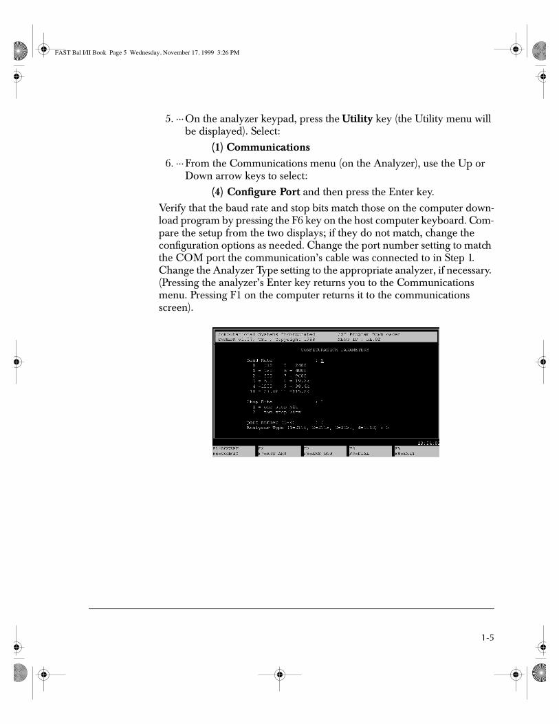
5. ···On the analyzer keypad, press the Utility key (the Utility menu will be displayed). Select:
(1) Communications6. ···From the Communications menu (on the Analyzer), use the Up or
Down arrow keys to select:
(4) Configure Port and then press the Enter key.
Verify that the baud rate and stop bits match those on the computer down-load program by pressing the F6 key on the host computer keyboard. Com-pare the setup from the two displays; if they do not match, change the configuration options as needed. Change the port number setting to match the COM port the communication’s cable was connected to in Step 1. Change the Analyzer Type setting to the appropriate analyzer, if necessary. (Pressing the analyzer’s Enter key returns you to the Communications menu. Pressing F1 on the computer returns it to the communications screen).
2
FAST Bal I/II Book Page 5 Wednesday, November 17, 1999 3:26 PM

1-6 FAST Bal I/II Quick Start Reference
The date and time setting on the Analyzer and the host computer must be within three hours of each other or an error message will be displayed. Refer to the appropriate machinery analyzer user’s manual for details on how to change the date/time on the analyzer.
7.···· Return to the Communications menu of the Analyzer. Use the Up/Down arrow keys to select (6) Load Downld Prog, then press Enter. The Select Program for Load menu will be displayed.
8. ··· Select Balance-Main (FAST Bal I or FAST Bal II on 2120) and press Enter. The message “Downloadable Program Load in Progress” will be displayed during the loading process. After loading is complete, the Communications menu will be displayed.
Caution!Do not interrupt the downloading process. Also, if you do not have enough memory or downloadable slots, FAST Bal will not load suc-cessfully.
9. ··· Exit the Download program by pressing the F10 key. Then, remove the installation disk from drive A: (or B:) and store it in a secure, protected place.
FAST Bal I/II Book Page 6 Wednesday, November 17, 1999 3:26 PM

1-7
Windows® Download Procedure
1.····Connect the analyzer to the COM1, COM2, COM3, or COM4 port of the computer using the supplied communications cable.
2. ···On the computer, place the floppy disk containing the firmware into drive A (or B).
3. ···From Windows, select the Start button and then choose Run. Type “A:\LOADFW.EXE” (or “B:\...” if B is the drive). Then, select the Ok button. Depending on whether this application has previously run, either the Main Menu or Configuration screen will be displayed. Note: The screens may be configured differently than what is shown.
Figure 3. Windows Downloader Configuration Screen
FAST Bal I/II Book Page 7 Wednesday, November 17, 1999 3:26 PM

1-8 FAST Bal I/II Quick Start Reference
Figure 4. Windows Downloader Main Menu
4. ··· If the Main Menu is displayed, select the Config button to display the Configuration screen. Otherwise, the Configuration screen is already displayed.
5. ··· On the Analyzer keypad, press the Utility key. The Utility menu will be displayed. Select:
(1) Communications
6. ··· From the Communications menu (on the Analyzer), use the Up or Down arrow keys to select:
(4) Configure Port
7.···· Press the Enter key.
Verify that the baud rate and stop bits match those on the computer down-load program. Compare the setup from the two displays. If they do not match, change the configuration options as needed. Change the COM port setting to match the COM port the communications cable was connected to in Step 1. If necessary, change the Analyzer Type setting to the appro-priate analyzer. (Pressing the analyzer’s Enter key returns you to the Com-munications menu. Clicking the OK button on the computer returns it to the communications screen.)
FAST Bal I/II Book Page 8 Wednesday, November 17, 1999 3:26 PM

1-9
The date and time setting on the analyzer and the host computer must be within three hours of each other or an error message will be displayed. Refer to the machinery analyzer user’s manual for details on how to check and change the date and time on the analyzer.
8. ···Return to the Communications menu of the analyzer. Use the Up/Down arrow keys to select (6) Load Downld Prog, then press Enter. The Select Program for Load menu will be displayed.
9. ···Select Balance-Main (FAST Bal I or FAST Bal II on 2120) and press Enter. The message “Downloadable Program Load in Progress” will be displayed during the loading process. After loading is complete, the Communications menu will be displayed.
Caution!Do not interrupt the downloading process. Also, if you do not have enough memory or downloadable slots, FAST Bal will not load suc-cessfully.
10.··Exit the download program by clicking the Exit button. Then, remove the installation disk from drive A: (or B:) and store it in a secure, protected place.
CatalogDisplays information (i.e., program name, version number, task file and name, and serial number) about the Analyzer disk placed in the drive.
Figure 5. Windows Catalog information
FAST Bal I/II Book Page 9 Wednesday, November 17, 1999 3:26 PM

1-10 FAST Bal I/II Quick Start Reference
Communication With UltraMgr
Once UltraMgr has been installed on the host computer, by completing the steps in one of the following procedures, depending on whether UltraMgr is MasterTrend compatible or RBMware compatible, FAST Bal I/II can store data to or retrieve data from a database:
MasterTrend/UltraMgr Communications Procedure1. ··· Attach the communications cable between the computer and the
analyzer.
2. ··· Start the UltraMgr Program on the computer and select Balance Functions.
3a. · At the computer, select Communications (F4), then select Comm Setup (F7).
3b.· At the analyzer, first select Utility. Next, select Communications. Then, select Configure Port.
3c. · Verify that the communications set-up for both the computer and analyzer are the same. Then, click the OK button on the computer screen and press the Enter key on the analyzer to accept any changes.
4. ··· At the Analyzer (with FAST Bal I/II active):
a.Store the Current Job:
i.Select Options from the Main Balance Menu,
ii.Select 1) Store Job from the Options Menu.
b.Select 6) Load/Dump Data from the Options Menu.
5. ··· At the computer, select:
a.“Upload Jobs to Database” to transfer jobs from the analyzer to the UltraMgr database, or,
b.“Download Jobs to Analyzer” to transfer jobs from UltraMgr to the analyzer.
Refer to the MasterTrend/UltraMgr User's Manual for additional informa-tion.
FAST Bal I/II Book Page 10 Wednesday, November 17, 1999 3:26 PM

1-11
RBMware/UltraMgr Communications Procedure1.····Attach the communications cable between the computer and the
analyzer.
2. ···First, start the RBMware Program on the computer. Next, select the Corrective Jobs button. Then, select the Setup/Communications tab. Now, select Corrective Data Transfer.
3a. ·At the computer, select Comm Setup (F7).
3b. ·At the analyzer, first select Utility. Next, select Communications. Then, select Configure Port.
3c.··Verify the communications set-up for both the computer and the analyzer are the same. Click Ok on the computer screen and press the Enter key on the analyzer to accept any changes.
4. ···At the Analyzer (with FAST Bal I/II active):
a.Store the Current Job:
i.Select Options from the Main Balance Menu,
ii.Select 1) Store Job from the Options Menu.
b.Select 6) Load/Dump Data from the Options Menu.
5. ···At the computer, select:
a.“Upload Jobs to Database” to transfer jobs from the analyzer to the UltraMgr database, or,
b.“Download Jobs to Analyzer” to transfer jobs from UltraMgr to the analyzer.
c.“Download a Default Job” to transfer default jobs from UltraMgr to the analyzer.
Refer to the RBMware/UltraMgr User's Manual for additional informa-tion.
FAST Bal I/II Book Page 11 Wednesday, November 17, 1999 3:26 PM

1-12 FAST Bal I/II Quick Start Reference
Select the Preferred Balance Mode
Before defining your first balance job, use the Balance Options menu (shown below) to decide which mode of operation you want to use.
6
Balance Mode Select option OverviewThis option allows you to select either of two balance modes, Basic or Stan-dard. The Standard mode is the recommended mode of operation allowing full utilization of all features offered by FAST Bal I/II.
The Basic mode offers a simplified setup but reduced flexibility and fea-tures. However, for many users, this may satisfy their needs and be the pre-ferred mode of operation. Select (8) Balance Mode Select to bring up the following screen.
FAST Bal I/II Book Page 12 Wednesday, November 17, 1999 3:26 PM

1-13
7
Highlighting Balance Mode and pressing any key allows you to toggle between either of two balance modes:
• Standard – see previous explanation.
• Basic – see previous explanation.
When Basic is displayed, you are also asked to specify this information:
• Reference Loc – this is the preferred location on graphic plots for the 0° reference point. Use any key to toggle between Top, Bottom, Left, or Right. The location will be identified with a “T” on graphic plots (signifying the Tach reference position). This setting is for your convenience only and will not affect the calculated solutions.
NoteA job defined as Basic can be upgraded later to Standard by changing this setting. However, you must then go through the normal Job Definition screens before proceeding. A job defined as Standard cannot be changed to Basic without having to define a new job.
The trade-off for using the simpler Basic mode is the loss of some features available when using the full Job Definition of the Standard mode.
• Limited to 2 planes, 2 sensors, and 1 speed instead of 4 planes, 8 sen-sors, and 6 speeds.
• Automatic checking of data between sensors for structural flexibility/resonance is disabled (FAST Bal II feature only).
FAST Bal I/II Book Page 13 Wednesday, November 17, 1999 3:26 PM

1-14 FAST Bal I/II Quick Start Reference
• Automatic splitting of weights for discrete weight planes is unavail-able.
• Estimate Trial Weight and calculate Amplification Factor/System Lag is unavailable. (FAST Bal II feature only).
• Customized Measurement Point labels and identification of sensor position is unavailable.
Define the Default Balance Sensor
From the Options menu, use the Default Sensor Setup function to define the standard sensor, vibration units, and MUX setting to be used. The Standard mode allows you to modify these settings any time a new job is defined. The Basic mode, however, uses the settings defined here. Changes to these set-tings only affect jobs created after the changes are made.
For detailed information about these settings, see the FAST Bal User’s manual provided with this package.
8
The AUTO setting is only available with the FAST Bal II package. Set MUX Enabled to ON or AUTO only if using the CSI Model 642 (2115/2117) or 648 (2120) 4-channel multiplexer. The AUTO function automati-cally acquires data for all defined MUX channels after channel one data acquisition is initiated.
When using AUTO, if the data does not stabilize enough for the program to automatically accept it, use the Enter key to over-ride.
FAST Bal I/II Book Page 14 Wednesday, November 17, 1999 3:26 PM

1-15
Recommended Setup For the Balance Job
Most balancing jobs have either one or two planes (called weight planes) in the rotor where weight corrections are made. The rotor is typically sup-ported by two bearings. In these situations, place two vibration sensors at each bearing with approximately 90° between them. Use horizontal and vertical positions if possible. If you are using the Basic mode, place one sensor at each bearing.
With its mounted sensors, each bearing constitutes one measurement plane. If these recommendations are followed, the setup to supply data to the FAST Bal program will be either:
• 1 Weight Plane with 2 Measurement Planes and 4 Sensors or,
• 2 Weight Planes with 2 Measurement Planes and 4 Sensors.
If you use a phototach, place a piece of reflective tape on the shaft or rotor. Then, position the phototach where it responds (the red light on the back of the phototach lights up) as the tape passes the location of the vertical or the horizontal vibration sensor.
This is strictly for convenience – any position will work if necessary.
Example Machine with Two Measurement Planes and Two Weight Planes
Rotor to beBalanced
Measurement Plane 1
Measurement Plane 2
WeightPlane 1
WeightPlane 2
Motor
Horz
Vert
End View
Reflective tape
Phototach
Note: This view showsthe recommendedsensor configurationwith two sensors ateach measurementplane.
FAST Bal I/II Book Page 15 Wednesday, November 17, 1999 3:26 PM

1-16 FAST Bal I/II Quick Start Reference
Using FAST Bal I or FAST Bal II
Both programs use the same basic flow and require the same set-up data. The most visible difference is that FAST Bal II uses numerous graphical displays for feedback, whereas FAST Bal I is entirely text based. There are several other features, such as special calculations and data checking which may not be as obvious; check the feature comparison table at the end of this document for a complete list of differences.
FAST Bal I/II is designed to lead you through all necessary steps. Just Begin with step 1, Job Definition and let the program lead the way. If addi-tional assistance is needed at any point, press the Help key if using the 2120, the Alt key if using the 2117, or the Keypad key if using the 2115 for a help message related to your current task.
1.····Define The Balance JobFAST Bal I FAST Bal IIBegin by defining the balance job; press Enter to select highlighted selec-tion.
FAST Bal I/II Book Page 16 Wednesday, November 17, 1999 3:26 PM
1-17
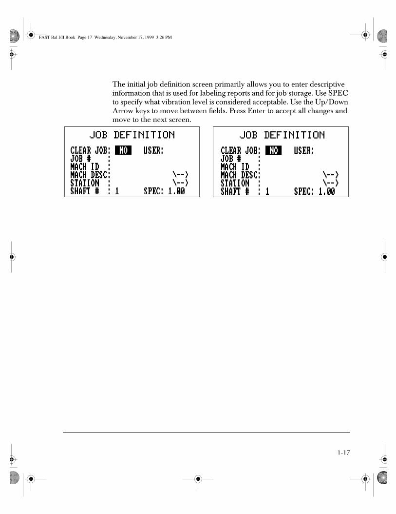
The initial job definition screen primarily allows you to enter descriptive information that is used for labeling reports and for job storage. Use SPEC to specify what vibration level is considered acceptable. Use the Up/Down Arrow keys to move between fields. Press Enter to accept all changes and move to the next screen.
FAST Bal I/II Book Page 17 Wednesday, November 17, 1999 3:26 PM

1-18 FAST Bal I/II Quick Start Reference
Job Definition (continued) – Basic Balance Mode
NoteThis feature is the same for both FAST Bal I and FAST Bal II.
After accepting the Job Definition screen, the following screen is displayed.
9
Explanations of the two options are:
• Configuration – use any key to toggle between 1 plane 1 sensor, 1 plane 2 sensors, or 2 planes 2 sensors.
• Rotation Dir – use any key to toggle between CW (clockwise) and CCW (counter clockwise). This is the direction of rotation at the end considered by you to be the reference end. Your choice will affect the orientation of graphics plots.
The program automatically labels the two sensors as IB (for inboard) and OB (for outboard) bearing. Use of the Horizontal or Vertical position is up to you. The best results will usually be obtained by measurements at both bearings.
The balance sensor and MUX definitions are the same as the setup speci-fied for the Default Balance Sensor option (accessed by using the Options key). If a different setup is desired, it must be defined before the new job is created. When using the MUX, the IB sensor is channel 1 and the OB sensor is channel 2.
Job definition for the Basic balance mode is now complete!
FAST Bal I/II Book Page 18 Wednesday, November 17, 1999 3:26 PM

1-19
Job Definition (continued) – Standard Balance Mode
FAST Bal I FAST Bal IIThe next screen provides the information needed to create a data matrix for this job. See “Recommended Setup For the Balance Job” on page 1-15 for an explanation of the entries for planes and points. At Discrete Weight Positions, answer Yes if any of the weight correction planes have a number of fixed positions for weight placement.
The location of all sensors relative to TDC (top dead center) is requested (this information is used to record the setup and for special calculations). Please note that all angles are measured against the direction of rotation. For the machine shown in “Example Machine with Two Measurement Planes and Two Weight Planes” on page 1-15, the Tach pick-up is 90° from TDC. The DIRection OF ROTATION is used as a default for any graphic displays or graphical print-outs (it does not affect the calculations).
DELTA RPM is the RPM value which will be added to and subtracted from the reference balance speed to establish a window for valid data. Enter “0” at Delta RPM to disable this function.
FAST Bal I/II Book Page 19 Wednesday, November 17, 1999 3:26 PM

1-20 FAST Bal I/II Quick Start Reference
FAST Bal I FAST Bal II• Describe the vibration sensor which will be used for all measure-
ments. If the CSI 642 MUX (or 648) is used, set MUX ENABLED to ON.
Describe the measurement positions which will be used for data acquisi-tion. Measurements at the same bearing should be designated as having the same measurement plane. Enter three characters/numbers to be used as the ID for each measurement location. Enter the angle of each sensor from TDC (see example machine in “Example Machine with Two Measurement Planes and Two Weight Planes” on page 1-15). When used with the Model 642/648 MUX, the channel number controls the MUX.
FAST Bal I/II Book Page 20 Wednesday, November 17, 1999 3:26 PM

1-21
Use the graphics with FAST Bal II to verify the accuracy of the set-up infor-mation. Compare these screens to the machine in “Example Machine with Two Measurement Planes and Two Weight Planes” on page 1-15.
FAST Bal I/II Book Page 21 Wednesday, November 17, 1999 3:26 PM

1-22 FAST Bal I/II Quick Start Reference
FAST Bal I FAST Bal IIWhen discrete weight planes are specified at the second job definition screen, the following additional screens will be displayed. Enter the number of available weight positions and the angle of position 1 from the tach reference (reflective tape, keyway, etc.). Be sure to tell FAST Bal which direction the positions are numbered relative to rotation.
If one of the available weight planes is continuous (weight may be placed at any angle or at irregularly located positions), then enter “1” for Weight Positions. All other entries for this plane can be ignored.
NoteThe remaining screens are similar for both the Standard and Basic balance modes except where features are not supported under Basic mode.
FAST Bal I/II Book Page 22 Wednesday, November 17, 1999 3:26 PM

1-23
2. ···Make Measurements
FAST Bal I FAST Bal IIWhen the job definition has been completed, the program returns to the Balance Functions menu. Job Definition is marked as complete ([X]) and the next logical step is highlighted. Simply press Enter to proceed.
A list of the data runs required for this job is shown. Choose the Reference Run to acquire data “as is”, before any changes are made.
FAST Bal I/II Book Page 23 Wednesday, November 17, 1999 3:26 PM

1-24 FAST Bal I/II Quick Start Reference
You are shown a list of the measurement points (MPT's) which were defined. Highlight any point and press Enter to begin data acquisition (ensure that the correct sensor is connected before pressing Enter). If you are using a 642/648 MUX, before beginning, connect all cables and the software will select the assigned channel.
NoteFAST Bal I shows instantaneous information on the left side of the screen and averaged data on the right. FAST BAL II dis-plays the instantaneous RPM, average magnitude, and phase as text.
FAST Bal I/II Book Page 24 Wednesday, November 17, 1999 3:26 PM

1-25
FAST Bal I FAST Bal IIData acquisition screens for both programs are shown below. Allow the data to stabilize before pressing Enter to accept a measurement. This means getting to the point where there is less than 5° variation in the average phase and less than 10% variation in the average amplitude. FAST Bal I shows instantaneous information on the left side of the screen and averaged data on the right. Fast Bal II displays the instantaneous RPM, average magni-tude, and phase as text. The graphical display for FAST Bal II shows the instantaneous vector as a line with a box at the end. The line drawn to each side of the instantaneous vector shows the minimum and maximum vector plotted. The small cross-hair on the plot represents the average phase and amplitude vector.
You are returned to the Select Measurement screen after each measurement is completed until data has been acquired for all points. At that time, PROCEED TO NEXT STEP is highlighted. To repeat a measurement, use the Up/Down arrows to highlight the point of interest. Otherwise, press Enter to proceed.
FAST Bal I/II Book Page 25 Wednesday, November 17, 1999 3:26 PM

1-26 FAST Bal I/II Quick Start Reference
FAST Bal I FAST Bal IIFAST Bal continues to lead you through the balance procedure. Next, a test weight (trial weight) must be added (or removed) at one weight plane and new measurements acquired.
Before acquiring data, you must tell the program how much and where weight was added. Up to two weights can be specified in one plane. Please note that P1(D) stands for plane 1, discrete weight plane. Locations for dis-crete weight plane weights are preceded by “@” and are given as a position number. The units of weight (ounces, grams, etc.) must be consistent throughout the procedure. Discrete weight plane are not supported in Basic mode. See next page for comments about the continuous weight plane.
Measurements are acquired using the same process as for the reference run.
FAST Bal I/II Book Page 26 Wednesday, November 17, 1999 3:26 PM

1-27
FAST Bal I FAST Bal IIComplete all remaining trial runs using the same procedure.
A new weight must be added in a new weight plane for the next trial run. Either remove the previous weight or be sure it is also listed for this trial run. The P2(C) indicates that weight plane 2 was defined as continuous. Therefore, all positions are entered as angles (in degrees as measured against rotation from the leading edge of the reference mark).
All measurements are completed as before.
FAST Bal I/II Book Page 27 Wednesday, November 17, 1999 3:26 PM

1-28 FAST Bal I/II Quick Start Reference
3.····Calculate And Install Correction Weights
FAST Bal I FAST Bal IIWhen all measurements are complete, the Balance Functions menu is dis-played with the next step, Correction Weights, highlighted. This selection will calculate the balance solution after the Reference and Trial Runs have been completed.
Just as when entering the trial weights, the solution for the discrete weight plane, P1(D), is shown as a position number. The solution for the contin-uous weight plane, P2(C), is shown as an angle in degrees. Notice the dis-crete weight solution is split between the available positions. Remember, the Basic mode always uses continuous weight planes.
Pressing the Page key (2115/2117) or the Page Up key (2120) will toggle between a solution adding or removing weight. Use the Up/Down arrow key to toggle between a solution with trial weights (TW) removed or the last trial weights left in place.
FAST Bal I/II Book Page 28 Wednesday, November 17, 1999 3:26 PM

1-29
4. ···Check Result / Trim Run
FAST Bal I FAST Bal IIAfter the correction has been made, you should acquire data from the new condition to check the results. If the vibration has not been reduced suffi-ciently, then a trim calculation can be made to improve the balance further.
Enter the correction weights which were actually applied. Many times this will differ somewhat from the calculated solution due to various constraints.
FAST Bal I/II Book Page 29 Wednesday, November 17, 1999 3:26 PM

1-30 FAST Bal I/II Quick Start Reference
FAST Bal I FAST Bal IIFAST Bal II can estimate the Residual Vibration from the Applied Weights screen. The accuracy of this calculation varies with the linearity of the system. Any factor affecting data accuracy and repeatability will also influ-ence the result.
Check the results by selecting CHECK RESULT from the Tolerance Check/Trim menu.
FAST Bal I/II Book Page 30 Wednesday, November 17, 1999 3:26 PM

1-31
Data acquisition proceeds as before until all measurement points have new data.
FAST Bal I/II Book Page 31 Wednesday, November 17, 1999 3:26 PM

1-32 FAST Bal I/II Quick Start Reference
FAST Bal I FAST Bal IIWhen data acquisition is completed, the results are summarized. The FAST Bal II graphic shows the original data at the MPT symbol. Up to two of the most recent check runs are plotted at the other end of the lines. The circle at the center of the graphic marks the target amplitude (specification).
FAST Bal I/II Book Page 32 Wednesday, November 17, 1999 3:26 PM

1-33
FAST Bal I FAST Bal IIYou should now view the calculated trim correction. This step is required to complete a check run and also initiates data being assigned to the balance job.
If trim weights are to be used, add them without removing the initial bal-ance correction weights.
Job Completed:All steps have been performed. If trim weights were added, an additional check should be made.
FAST Bal I/II Book Page 33 Wednesday, November 17, 1999 3:26 PM

1-34 FAST Bal I/II Quick Start Reference
NotepadThe notepad allows notes to be attached to the balance job for later recall or printing. The process is the same for Fast Bal I and II. Press the NOTES key to access the Balance Notepad. Pre-defined notes are available from four categories, or user defined notes may be created by selecting USER DEFINED.
10
Once a category has been selected, highlight the number of the desired note and press Enter to attach it to the balance job. When attached to a job, the entire note becomes highlighted.
11
Press Reset to return to the Balance Function menu. Notice the lower left corner shows one note has been assigned to this balance job.
12
FAST Bal I/II Book Page 34 Wednesday, November 17, 1999 3:26 PM

1-35
OptionsFAST Bal I FAST Bal IISelecting (5), OPTIONS, from the Balance Functions menu displays the Balance Options Menu. The first three selections control job storage in the analyzer itself. You can also review and edit data as shown below. Auxiliary calculations can be made for special circumstances using Calculator Mode. Load/Dump Data transfers data to and from UltraMgr. Print Report gener-ates hardcopy reports directly from the analyzer.
Caution!DO NOT connect the printer directly into the RS232 port located on the top panel of the analyzer.
For an explanation of Balance Mode Select and Default Sensor Set-up, see “Select the Preferred Balance Mode” on page 1-12 and “Define the Default Balance Sensor” on page 1-14.
REVIEW/EDIT DATA is the same for both programs except that FAST Bal II will display the calculated influence coefficients.
FAST Bal I/II Book Page 35 Wednesday, November 17, 1999 3:26 PM

1-36 FAST Bal I/II Quick Start Reference
In Calculator Mode, FAST Bal II has additional calculations for Trial Weight/Heavy Spot estimations and Amplification Factor calculations.
FAST Bal I/II Book Page 36 Wednesday, November 17, 1999 3:26 PM

1-37
Feature Comparison Of Products
DescriptionFAST
BalancingFASTBal I
FASTBal II
UltraSpecBalance
Menu leads user through procedure No Yes Yes Yes
On-line Help No Yes Yes Yes
Note Pad No Yes Yes Yes
Database BalMgr MasterTrend, UltraMgr, &RBMware
MasterTrend, UltraMgr, &RBMware
MasterTrend, UltraMgr, &RBMware
Maximum number of sensors 4 8 8 8
Maximum number of planes 4 4 4 4
Maximum number of speeds 6 6 6 6
Stores sensor positions No Yes Yes Yes
MasterTrend compatible MPT ID’s, machine description, and station
No Yes Yes Yes
Graphics assist job setup No No Yes Yes
Graphics assist weight location No No Yes Yes
Graphic data acquisition No No Yes Yes
Check results table No Yes Yes Yes
Check results graphic No No Yes Yes
Define discrete weight planes No Yes Yes Yes
Automatic weight splitting No Yes Yes Yes
Split weights, sum weights, adjust fixed weights, and static/couple calculations
Yes Yes Yes Yes
Trial weights estimation No No Yes Yes
Amplification factor and system lag calculations
No No Yes Yes
Residual vibration calculation No No Yes Yes
Available balance solutions 1 4 4 4
RPM window for valid data No Yes Yes Yes
FAST Bal I/II Book Page 37 Wednesday, November 17, 1999 3:26 PM

1-38 FAST Bal I/II Quick Start Reference
Note(1) FAST Balancing is the program which was replaced by FAST Bal I. (2) All features are subject to change.
Reference data evaluated for potential problems
No No Yes Yes
Built-in reports 0 1 4 4
Table of influence coefficients No No Yes Yes
Program can control MUX No Yes Yes Yes
Automatic MUX mode No No Yes Yes
Correction weights stored with job No Yes Yes Yes
Page “BACK” key No Dele key - 2115/2117;Page Down - 2120
Dele key - 2115/2117;Page Down - 2120
Page Up key
User defined default sensor No Yes Yes Yes
Basic and Standard balancing modes No Yes Yes Yes
Averaged and non-averaged data displayed simultaneously
No Yes Yes Yes
Data stability evaluated No No Yes Yes
DescriptionFAST
BalancingFASTBal I
FASTBal II
UltraSpecBalance
FAST Bal I/II Book Page 38 Wednesday, November 17, 1999 3:26 PM