fatigue analysis of a railway hydraulic damper with
TRANSCRIPT

Fatigue Analysis of A Railway Hydraulic Damper with Welding Imperfections under Actual In-service Load Conditions
Wen-lin WANG1,*, Bao HUANG1,2, Jian-ming DU2 and Simon Iwnicki3
1School of Mechanical Engineering, Dongguan University of Technology, Dongguan 523808, China 2College of Mechatronics and Control Engineering, Shenzhen University, Shenzhen 518060, China
3Institute of Railway Research, University of Huddersfield, Huddersfield HD1 3DH, UK
*Corresponding author
Keywords: Hydraulic damper, Fatigue, In-service load, Welding imperfection, Stress.
Abstract. Fatigue analysis of a railway vehicle axle-box hydraulic damper was carried out in this study. The damping force profiles under nominal and actual in-service load conditions were simulated, and the corresponding load spectra were obtained using the rain-flow cycle counting approach. Further fatigue analyses of the hydraulic damper under nominal and actual in-service load spectra and with welding imperfections were conducted. Results demonstrate that the maximum local stress of the damper would increase and fatigue life would be remarkably reduced when using the actual in-service load spectra. If the damper also has multiple welding imperfections, such as with porosities and misalignment of parts, the damper would be readily subject to premature failures. For this reason, many current high-speed rail hydraulic dampers are still subject to premature failures despite being designed to nominal load cases. Thus, a nonlinear in-service damper model and the actual in-service load spectra should be used in further damper structural development, the results obtained in this study could also be instructive in improving damper structure welding technique and inspection.
Introduction
In recent years, rail vehicle speeds and loads have greatly increased and vehicle maintenance reports show that some key components such as the hydraulic dampers are now frequently subject to premature failures. In the case of failures of welded joints, fractures of the axle-box and yaw damper attachments, which may threaten vehicle safety, more frequent inspections are required.
Many previous researchers have addressed fatigue analyses of welded structures of rail vehicle bogie frames [1, 2], wheel/rail rolling contact [3] and rail welded joints [4] by using simulated and/or tested loading spectra with Finite Element Analyses (FEA). The rain-flow cycle counting method [5] was often used to obtain load spectra, the variable amplitude loading conditions [6] and weld residual stress [7] were also considered in the fatigue behaviour analysis of steel structures.
Service failures of an automobile shock absorber [8] with welding imperfections were investigated, and the fretting fatigue failure and crack under cyclic loading of the shim valve of an automotive shock absorber [9] was also studied. However, research concerning failures of railway hydraulic damper structures and the reasons why railway hydraulic dampers are still subject to premature failures under actual in-service load conditions, need further investigation.
Fatigue analyses of an axle-box hydraulic damper installed in a Chinese high-speed electric locomotive was carried out in this study. The nominal and actual in-service load spectra were obtained using the rain-flow cycle counting approach, fatigue analyses of the hydraulic damper under different load spectra and with various welding imperfections were conducted, valuable results were obtained to illustrate the reason why many current high-speed rail hydraulic dampers are still subject to premature failures despite being designed to nominal load cases. The results obtained in this work could also be instructive in improving damper structure welding technique and inspection.
International Conference on Modeling, Analysis, Simulation Technologies and Applications (MASTA 2019)
Copyright © 2019, the Authors. Published by Atlantis Press. This is an open access article under the CC BY-NC license (http://creativecommons.org/licenses/by-nc/4.0/).
Advances in Intelligent Systems Research, volume 168
371

Actual In-service Load Spectra
Using the high-speed electric locomotive simulation model established in literature [10], simulation was performed when both a conventional axle-box damper model and an actual in-service damper model were respectively incorporated, and the corresponding load profiles and their rain-flow cycle counting results of the axle-box hydraulic damper were obtained, as shown by Fig. 1.
Figure 1 illustrates that the actual in-service load spectra involve many dead-zone-induced impact peaks, the scattering range and rain-flow cycle counts of the maximum damping forces of the actual in-service load spectra and are much larger than that of the nominal load spectra.
Figure 1. (a) Nominal load profile and its rain-flow cycle counting result (the minimum and maximum damping forces) of an electric locomotive axle-box hydraulic damper when a conventional damper model was used, (b) Actual in-service load profile and its rain-flow cycle counting result of the axle-box damper (Simulation conditions: vehicle speed 160 km/h in tangent track, time: 10 s, a 1.5 mm fitting clearance of the damper was used in the in-service load simulation)
Fatigue Analysis
FEA Modelling
In order to perform fatigue analysis of the axle-box hydraulic damper using the obtained load spectra, A FEA model of the rod-and-attachment assembly of the hydraulic damper was built in the ANSYS environment, as shown by Fig. 2.
Figure 2. FEA model of the rod-and-attachment assembly of the axle-box hydraulic damper
Advances in Intelligent Systems Research, volume 168
372
In the modeling process, the No. 20 steel with Density of 7850 kg/m3, Elastic Modulus of 2.06e+5 MPa, Poisson’s Ratio of 0.3, Yield Strength of 254 MPa, Strength of Extension of 392 MPa and Fatigue Strength of 59.4 MPa are used; The solid186 element is used to model the steel and welding seams, the whole FEA model has 16851 elements with 56120 nodes.
Fatigue Analysis
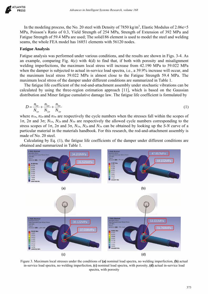
Fatigue analysis was performed under various conditions, and the results are shown in Figs. 3-4. As an example, comparing Fig. 4(c) with 4(d) to find that, if both with porosity and misalignment welding imperfections, the maximum local stress will increase from 42.190 MPa to 59.022 MPa when the damper is subjected to actual in-service load spectra, i.e., a 39.9% increase will occur, and the maximum local stress 59.022 MPa is almost close to the Fatigue Strength 59.4 MPa. The maximum local stress of the damper under different conditions are summarized in Table 1.
The fatigue life coefficient of the rod-and-attachment assembly under stochastic vibrations can be calculated by using the three-region estimation approach [11], which is based on the Gaussian distribution and Miner fatigue cumulative damage law. The fatigue life coefficient is formulated by
1 2 3
1 2 3
n n nD
N N N
(1)
where n1σ, n2σ and n3σ are respectively the cycle numbers when the stresses fall within the scopes of 1σ, 2σ and 3σ; N1σ, N2σ and N3σ are respectively the allowed cycle numbers corresponding to the stress scopes of 1σ, 2σ and 3σ, N1σ, N2σ and N3σ can be obtained by looking up the S-N curve of a particular material in the materials handbook. For this research, the rod-and-attachment assembly is made of No. 20 steel.
Calculating by Eq. (1), the fatigue life coefficients of the damper under different conditions are obtained and summarized in Table 1.
Figure 3. Maximum local stresses under the conditions of (a) nominal load spectra, no welding imperfection, (b) actual
in-service load spectra, no welding imperfection, (c) nominal load spectra, with porosity, (d) actual in-service load spectra, with porosity
Advances in Intelligent Systems Research, volume 168
373

Figure 4. Maximum local stresses under the conditions of (a) nominal load spectra, misalignment of rod and attachment,
(b) actual in-service load spectra, misalignment of rod and attachment, (c) nominal load spectra, with porosity, misalignment of rod and attachment, (d) actual in-service load spectra, with porosity, misalignment of rod and attachment
Table 1. A comparison of the key fatigue indices of the hydraulic damper under various conditions
Load Spectra Maximum Local Stress
(MPa)/Change Fatigue Life
Coefficient/Change
No welding imperfection Nominal 34.209
↑39.9% 0.3994
↑40.7% Actual in-service 47.857 0.5620
With porosity Nominal 38.122
↑39.9% 0.4250
↑100.1% Actual in-service 53.331 0.8922
Misalignment of rod and attachment Nominal 34.900
↑39.9% 0.4001
↑47.4% Actual in-service 48.824 0.5896
With porosity and misalignment of rod and attachment
Nominal 42.190 ↑39.9%
0.7605 ↑25.6%
Actual in-service 59.022 0.9549
Table 1 shows that the maximum local stress will increase about 39.9% when the damper is subjected to actual in-service load spectra, and fatigue life coefficient will increase (i.e., the fatigue life will decrease) about 25.6% to 100.1% according to the conditions of welding imperfections. Particularly, the gas porosity in the welding seam has a great effect on the stress and fatigue life of the damper structure, if with porosity welding imperfection and under actual in-service load condition, a hydraulic damper is readily subject to premature failures.
Advances in Intelligent Systems Research, volume 168
374

Concluding Remarks
(1) Actual in-service load spectra of the hydraulic damper are affected by key in-service parameter variations, so the actual in-service load spectra have many impact peaks and are much stronger than the load spectra obtained when a conventional damper model is used.
(2) The maximum local stress of the damper would increase and fatigue life would be remarkably reduced when using the actual in-service load spectra. If the damper also has multiple welding imperfections, such as with porosities and misalignment of parts, the damper would be readily subject to premature failures. This is why many current high-speed rail hydraulic dampers are still subject to premature failures despite being designed to nominal load cases.
(3) A nonlinear in-service damper model and the actual in-service load spectra should be used in further damper structural development, the results obtained in this study could also be instructive in improving damper structure welding technique and inspection.
Acknowledgement
The authors are grateful for financial support from the National Natural Science Foundation of China (NSFC) under Grant No. 11572123 and the Research Fund for High-level Talent of Dongguan University of Technology under Project No. GC200906-30.
References
[1] A. Esderts, J. Willen, M. Kassner, Fatigue strength analysis of welded joints in closed steel sections in rail vehicles, Int. J. Fatigue 34(1) (2012) 112-121.
[2] J.W. Han, J.D. Kim, S.Y. Song, Fatigue strength evaluation of a bogie frame for urban maglev train with fatigue test on full-scale test rig, Eng. Fail. Anal. 31 (2013) 412-420.
[3] S. Ulrich, D,F. Robert, S.E. Pieter, The effect of rolling contact fatigue mitigation measures on wheel wear and rail fatigue, Wear 398-399 (2018) 56-68.
[4] C. Lu, J. Nieto, I. Puy, J. Melendez, J.M. Martínez-Esnaola, Fatigue prediction of rail welded joints, Int. J. Fatigue 113 (2018) 78-87.
[5] S.H. Baek, S.S. Cho, W.S. Joo, Fatigue life prediction based on the rainflow cycle counting method for the end beam of a freight car bogie, Int. J. Auto. Tech. 9(1) (2008) 95-101.
[6] G. Kasra, W. Scott, T. Tim, High cycle fatigue behaviour of impact treated welds under variable amplitude loading conditions, Int. J. Fatigue 81 (2015) 128-142.
[7] W.Y. Zhang, W.C. Jiang, X. Zhao, S.T. Tu, Fatigue life of a dissimilar welded joint considering the weld residual stress: Experimental and finite element simulation, Int. J. Fatigue 109 (2018) 182-190.
[8] J.M. Gallardo, L. Soria, E.J. Herrera, Investigation of service failures in automobile shock absorbers, Eng. Fail. Anal. 14 (2007) 355-363.
[9] H.T. Reza, Z. Ali, D.B. Patrick, Fretting fatigue failure mechanism of automotive shock absorber valve, Int. J. Fatigue 73 (2015) 58-65.
[10] W.L. Wang, Z.R. Zhou, D.S. Yu, Q.H. Qin, S. Iwnicki, Rail vehicle dynamic response to the nonlinear physical in-service model of its secondary suspension hydraulic dampers, Mech. Syst. Signal Pr. 95 (2017) 138-157.
[11] K.A. Macdonald, Fracture and fatigue of welded joints and structures, Woodhead Publishing Limited, Cambridge, UK, 2011.
Advances in Intelligent Systems Research, volume 168
375