fatigue analysis of flexible bodies with avl excite ... · avl pei 9 overview of avl excite...
TRANSCRIPT

Peter Van Wieren, Senior Technical SpecialistAVL PEIDynamic Simulation in Vehicle Engineering 3rd International Conference 2014
Fatigue Analysis of Flexible Bodies with AVL EXCITE, FEMFAT and ABAQUS using Modal Data Recovery

2AVL PEI
INTRODUCTION
� General overview of AVL and the AVL EXCITE engine simulation software
� Description of a new feature of AVL EXCITE which allows the use of modal stress recovery with the ABAQUS FE software and Magna-Steyr’s FEMFAT fatigue analysis software.
3AVL PEI
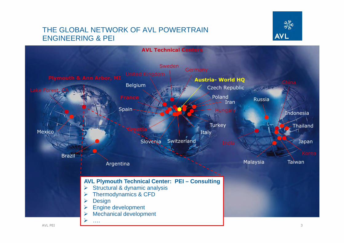
THE GLOBAL NETWORK OF AVL POWERTRAIN ENGINEERING & PEI
Austria- World HQ
Croatia
Czech Republic
France
Germany
Slovenia
Spain
Sweden
United Kingdom
Hungary
Poland
Belgium
Switzerland
Turkey
Iran
India
Italy
Brazil
Argentina
Mexico
China
Japan
Korea
Russia
Thailand
Indonesia
Malaysia Taiwan
Plymouth & Ann Arbor, MI
Lake Forest, CA
AVL Technical Centers
AVL Plymouth Technical Center: PEI – Consulting� Structural & dynamic analysis� Thermodynamics & CFD� Design� Engine development� Mechanical development� ….

4AVL PEI
passenger cars 2-wheelers racing
construction agriculture commercial vehicle
locomotive marine power plants
Engineering
Testing
AVL‘S SIMULATION SOFTWARE IS LEVERAGING FROM THE SYNERGIES OF ALL AVL BUSINESS UNITS
AVL PTE
Powertrain
Engineering
AVL AST
Advanced
Simulation
Technologies
AVL ITS
Instrumentation
and
Test Systems

5AVL PEI
AREA OF APPLICATION
� Cranktrain and powertrain design in the concept phase (EXCITE Designer)
� Hydrodynamics bearing analysis
� Torsional crankshaft vibrations
� Crankshaft strength analysis
� Transient strength analysis
� Crankshaft
� Connecting Rod
� Piston
� Main Bearing Wall
� Flywheel Whirl

6AVL PEI
AREA OF APPLICATION
� NVH of power units
� Low frequency vibration analysis (engine mounts)
� Radiated noise
� Turbocharger and accessories
� Advanced EHD contact simulation
� Slider bearing design
� Slider bearing failure
� Piston-liner contact analysis
� Detailed investigation in friction losses
� Dynamics / acoustics of transmissions and drivelines
� Analysis of in-stationary conditions� High frequency noise phenomena

7AVL PEI
100 1000Displacement - [L]
I4 Diesel
V10 Diesel
V16 Marine
V8 Marine
9 Cyl. Marine
W12 Gasoline
I4 Diesel
110
100
1000
10000
Pow
er -
[kW
]
10
1 Cyl. Motorcycle
I4 Gasoline
V6 Gasoline
V10 Racing
EXCITE CRANKSHAFT STRENGTH ANALYSIS –PROVEN FOR ANY ENGINE SIZE
I4 Gasoline

8AVL PEI
Radial Slider Bearing,Axial Thrust Bearing,Piston / Liner Contact,Rotational Coupling, ...
Nonlinear Bearing Forces and Moments
calculated due to Actual Dynamics of
Parts
VibratingStructure Parts
Vibrating, Rotating, Oscillating Structure Parts
OVERVIEW OF AVL EXCITEMULTIBODY DYNAMIC SIMULATIONS
Flexible MBS under transient conditions:
� Flexible bodies represented by linear FE models, such as:
� Engine Block
� Crankshaft
� Connecting Rod
� Non-Linear Joints: connect the rigid bodies, such as:
� Simple Joints (e.g. Revolute)
� Engine Mounts
� Highly complex thermo elasto-hydrodynamic joints including mixed lubrication
� Excited by external forces
Gas Excitation
Valve Train Excitation
Piston Slap
Excitation Forces and Moments
Excitation from Injection System
9AVL PEI
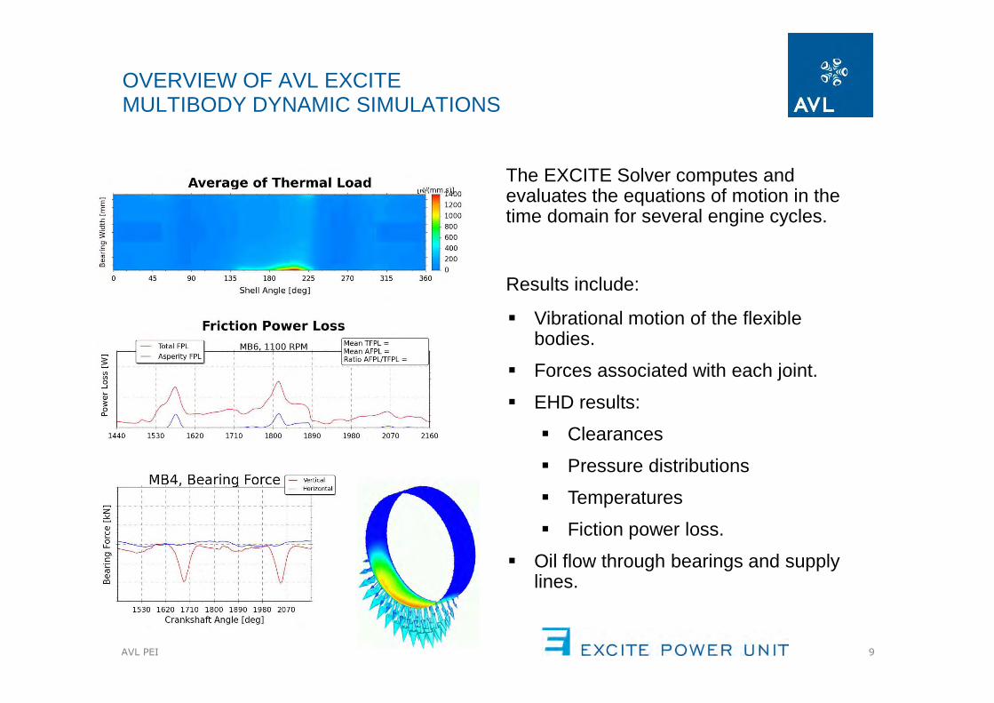
OVERVIEW OF AVL EXCITEMULTIBODY DYNAMIC SIMULATIONS
The EXCITE Solver computes and evaluates the equations of motion in the time domain for several engine cycles.
Results include:
� Vibrational motion of the flexible bodies.
� Forces associated with each joint.
� EHD results:
� Clearances
� Pressure distributions
� Temperatures
� Fiction power loss.
� Oil flow through bearings and supply lines.

10AVL PEI
EXCITE BODY PREPARATIONSUBSTRUCTURING PROCESS FOR FE MODELS
• Finite element models are used to create flexible bodies for AVL EXCITE.
• Substructuring is used to eliminate degrees of freedom to generate a reduced mass and stiffness matrix.
• Matrices (L) are stored which allow the retained DOF to be used to recover stress and displacement information for the full FE model.

11AVL PEI
• The main operation for recovering stresses is to carry out matrix multiplication:
• EXCITE provides a time-history of the retained degrees of freedom.
• FE stress data is stored in the “L” matrix found in the “.sim” file.
• An interface for FEMFAT to read the stress data in the ABAQUS “.sim” is not available.
• The new software tool reads the stress data from the “.sim” file, and directly creates the FEMFAT scratch files.
• This provides the ability to carry out fatigue analysis for stresses obtained through modal stress recovery.
NEW TOOL SUPPORTING FEMFAT FATIGUE ANALYIS WITH MODAL STRESS RECOVERY
ABAQUSSUBSTRUCTURE
EXCITESIMULATION
subRecovery.exe(New Tool)
FEMFATSCRATCH
MODAL SCALEFACTORS
FEMFATFATIGUE
ANALYSISABAQUS“.sim” File

12AVL PEI
APPLICATIONS AND LIMITATIONSOF MODAL STRESS RECOVERY
Advantages :
• Preprocessing effort for crankshaft fatigue analyses.
• Better accuracy for split pin V engines.
• Oil drilling breakout areas in crankshaft pins and main.
• The scratch files generated are common to different engine operating conditions.
• The ABAQUS substructuring procedure is quite fast: A typical crankshaft requires only one or two hours.
Limitations:
• Linear deformations of the flexible body are assumed. The assessment of stress states in locations which are characterized by non-linear behavior, such as bolted connections, should use other analysis methods.
• ABAQUS is limited to storing stress data for one “section point” to the “.sim” file, thus stresses cannot be fully recovered to shell and beam elements.

13AVL PEI
SHAFT MODELERADD DAMPER, FLYWHEEL
MESHING EACH WEB
CRANKSHAFT FATIGUE ANALYSISSTRUCTURED MODEL APPROACH - PROCESS OVERVIEW
CADGEOMETRY
AUTOSHAFT
FEA: STIFFNESS CALC
DYNAMIC SIMULATION
STIFFNESS MATRIX MANIPULATIONS TO
REPRESENT WEB ONLY
BEAM CRANKSHAFT

14AVL PEI
FATIGUE ANALYSISBY LINEAR
SUPERPOSITION
FINITE ELEMENT ANALYSIS OF EACH WEB
CRANKSHAFT FATIGUE ANALYSISSTRUCTURED MODEL APPROACH - PROCESS OVERVIEW
MOTION OF PIN/JOURNALCENTERS
• Stress analysis is carried out for each half throw with unit deflections.
• Fatigue analysis for each ½ throw is done using FEMFAT/ChannelMax with time histories from EXCITE.

15AVL PEI
The modal stress recovery approach involves fewer steps than the structured modeling.
The process uses the same FE structure for both the mass-elastic representation in EXCITE and also for the calculation of stresses.
Linear superposition is implemented through Magna Steyer’sfatigue software FEMFAT to calculate the fatigue safety factors in the FE model.
The entire crankshaft can be assessed in a single FEMFAT job.
RETAINED DOF ARE ADDED SUBSTRUCTURING
CRANKSHAFT FATIGUE ANALYSISMODAL STRESS RECOVERY APPROACH
CADGEOMETRY
DYNAMIC SIMULATION FATIGUE ANALYSIS
MESHING OF ENTIRECRANKSHAFT
SubRecovery.exeScratch File Generation
16AVL PEI
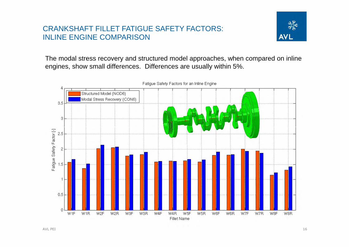
The modal stress recovery and structured model approaches, when compared on inline engines, show small differences. Differences are usually within 5%.
CRANKSHAFT FILLET FATIGUE SAFETY FACTORS:INLINE ENGINE COMPARISON

17AVL PEI
The modal stress recovery and structured model approaches yield fatigue safety factors with greater differences on V engines with split pins. Differences may be as great as 20%. The modal stress recovery provides greater numerical accuracy.
CRANKSHAFT FILLET FATIGUE SAFETY FACTORS:V ENGINE COMPARISON

18AVL PEI
The structured model approach assumes the stiffness for any ½ throw of the crankshaft is similar between the beam model used in EXCITE and the FE model used for the calculation of fillet stresses.
The similarity of the ½ throw stiffness matrix is better for inline than for V engines with split pins.
COMPARISON OF STIFFNESS OF STRUCTURED MODEL WEB AND FE MESH OF SINGLE WEB FOR STRESS ANALYSIS

19AVL PEI
The structured model approach requires placing a rigid body boundary condition through oil drilling breakout locations. The substructuring approach allows fatigue safety factors to be estimated at oil supply outlets as the rigid region can be reduced to a smaller size near the journal or pin axis.
OIL DRILLING BREAKOUT AREA FATIGUE ANALYSIS
Rigid cross section for each web in structured crankshaft method interferes with oil supply outlet
With substructuring and modal stress recovery it is not assumed the whole cross section is rigid.

20AVL PEI
The calculation time required to conduct a full crankshaft assessment, covering a range of engine speeds, is minimized by executing tasks in parallel. Sophisticated scheduling software is able to maximize the number of concurrent CAE tasks, while abiding by limitations to parallelization such as those imposed by token based software licenses. The image below shows actual calculation times from a recent project.
PARALLEL EXECUTION SCHEDULEWITH MODAL STRESS RECOVERY AND FATIGUE ANALYSIS

21AVL PEI
The 2014 release of AVL EXCITE will feature the new possibility of using the modal stress recovery processes with the following combination of software:
� ABAQUS – Finite Element Modeling.
� EXCITE – Multibody Dynamic Simulations of Combustion Engines.
� FEMFAT – Finite Element Fatigue Analysis.
Benefits of the new workflow for crankshaft fatigue analysis include:
• Improved numerical accuracy for V engine crankshafts with split pins.
• Analyst preprocessing and solution efforts can be reduced, leading to overall shorter analysis durations.
• The direct evaluation of oil bore breakout regions is possible through MSR.
SUMMARY AND CONCLUSION