fault recording system for indactic 650 professional … recording system for professional fault...
TRANSCRIPT

Page 1
Description Indactic® 650 - for maximum availability in electrical networks
Maximum availability is essential in the power generation and transmission sector. Faults in transmission lines, substations etc. can cause very serious damage. Therefore it is important to have means to examine each fault in detail, in order to detect weaknesses of the system. Indactic® 650 fault analyzing system records the history of a fault and per-mits its reconstruction and subsequent analy-sis. When a fault occurs, the system stores the wave forms and other states of the plant equipment. The cause and location of the fault can quickly be determined and the behavior of the associated control and protec-tion equipment can be evaluated. Concrete
measures can then be deduced from the anal-ysis of such faults, in order to prevent future failures. On the whole, the use of the fault recorder has advantages, which contribute to improving the availability of the plant:
• Causes of faults can be quickly detected,• Fault sources can be deduced,• The fault locating facility pinpoints the
geographical location of the fault,• Protective designs and switching strategies
can be refined,• Future faults can be prevented.
Fault Recording System for Professional Fault Analysis
Indactic® 6501MRB520255-Ben
Issued: July 1999Changed:
Version:Revision:
Status:Data subject to change without notice

Fault Recording System for Professional Fault Analysis
Indactic® 6501MRB520255-Ben
Page 2
Description (cont´d)Description (cont´d)
ABB Power Automation
Fig. 1 Block diagram showing all components. The lower section of the diagram shows several acquisi-tion units, while the upper section shows a local analysis station and one of several remote analy-sis stations. The diagram particularly demonstrates the modular structure and the resulting flexibility of use.
The Indactic® 650 is ABB's fourth generation of fault recorders, and has been developed basing on the extensive experience gained in the past. It is based on a compact autonomous fault acquisition unit, modular in structure. The size of the acquisition station depends on the number of signals to be monitored. Com-bining a suitable number of acquisition units into one network forms a station. This design
contains excellent characteristics with regard to flexibility, high availability and simplicity of installation.
The main benefit of the fault analysis system lies in fast, easy to operate graphical analysis facility. The Indactic® 650 provides function-ality that is difficult to beat by use of its 32-bit programs that run under the Windows® operating system.
IndBaseWinEve
ReCo
IndBaseWinEveWinCom
Fault Recording System for Professional Fault Analysis
Indactic® 6501MRB520255-Ben
Page 3
ABB Power Automation
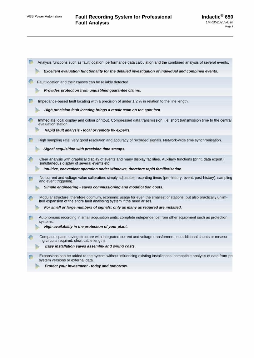
Analysis functions such as fault location, performance data calculation and the combined analysis of several events.
Excellent evaluation functionality for the detailed investigation of individual and combined events.
Fault location and their causes can be reliably detected.
Provides protection from unjustified guarantee claims.
Impedance-based fault locating with a precision of under ± 2 % in relation to the line length.
Clear analysis with graphical display of events and many display facilities. Auxiliary functions (print, data export);
Intuitive, convenient operation under Windows, therefore rapid familiarisation.
Simple engineering - saves commissioning and modification costs.
Modular structure, therefore optimum, economic usage for even the smallest of stations; but also practically unlim-
For small or large numbers of signals: only as many as required are installed.
Autonomous recording in small acquisition units; complete independence from other equipment such as protection
High availability in the protection of your plant.
Compact, space-saving structure with integrated current and voltage transformers; no additional shunts or measur-
Easy installation saves assembly and wiring costs.
Expansions can be added to the system without influencing existing installations; compatible analysis of data from pre
Protect your investment - today and tomorrow.
High precision fault locating brings a repair team on the spot fast.
Immediate local display and colour printout. Compressed data transmission, i.e. short transmission time to the centralevaluation station.
Rapid fault analysis - local or remote by experts.
High sampling rate, very good resolution and accuracy of recorded signals. Network-wide time synchronisation.
Signal acquisition with precision time stamps.
simultaneous display of several events etc.
and event triggering.No current and voltage value calibration; simply adjustable recording times (pre-history, event, post-history), sampling
ited expansion of the entire fault analysing system if the need arises.
systems.
ing circuits required; short cable lengths.
system versions or external data.

Fault Recording System for Professional Fault Analysis
ABB Power Automation Indactic® 6501MRB520255-Ben
Page 4
System structure The Indactic® 650 essentially comprises data acquisition and evaluation stations. The smallest acquisition station unit is a compact, autonomous unit. It is designed for 9 analog and 16 digital signal inputs. It contains the appropriate connections, potentially sepa-rated signal transformers and buffer storage for recorded events. Any number of units can be combined into a logical acquisition station, according to the number of signals and future expansion needs. A single coaxial and/or fib-re optical cable is used to interconnect the acquisition units for time synchronization and data transmission over a distance of up to 2 km. Communication with the evaluation sta-tion is performed by one of the nodes defined as a master.
This decentralized signal recording and mod-ularization of Indactic® 650 allows its easy integration into existing systems with little additional cabling work & engineering. All existing Indactic® 650 systems can be extended by adding acquisition units to adapt to new requirements.
The recording of events is event-driven. The start and stop times of the recording can be defined for all analog and digital signals. If a triggering criterion is met for an acquisition unit, all acquisition units in the acquisition station concerned are triggered at the same time. The recordings are buffered in an event file, which is sent to the evaluation station for analysis. The event data are transferred into the evaluation station via the transmission cable and the buffer in the acquisition unit is cleared, and ready for new recordings again.
Recording features• Compact acquisition unit with 9 analog
and 16 digital inputs and internal potential separation,
• Several acquisition units can be combined into one fault recorder, distributed over 2000 m with full time synchronization (±10 µs),
• Input of analog signals as current or volt-age values with high precision without special calibration,
• Analog to digital signal conversion with a resolution of 1/32 000 of the maximum value (16 bit),
• Correct signal representation by filtering out distorted inputs, since the input filter automatically adjusts to the set sampling rate,
• Power supply and digital inputs with a wide range of voltages, 48 V...250 V, potentially separated,
• Adjustable sampling rate for optimized data volumes and transmission times,
• Event recording times separately adjust-able for pre-fault, event and post-fault over a wide time range,
• Event triggering by digital signals, analog signals (exceeding limit values, gradients and mains frequency) or by exceeding symmetric component limit values,
• Data compression for fast transmission to evaluation station via usual remote trans-mission media,
• High level of data transmission security,• Network-wide time synchronization, using
an external clock.
Fig. 2 Function diagram of the Indactic® 650 acquisition unitCB-10 Field bus for interconnecting acquisition unitsTP Digital filter with data reductionALF Anti-aliasing filter

Fault Recording System for Professional Fault Analysis
ABB Power Automation Indactic® 6501MRB520255-Ben
Page 5
High functional-ity for evaluation and analysis
A commercially available PC with Windows and the Indactic application software is all that is required for analyzing events. One or more of these evaluation stations can be placed anywhere in the network. The data transmission between the acquisition and the evaluation stations is always automatic (call-back, inquiry, auto-answer), but can also be triggered manually.
H.V. transmission lines with carrier fre-quency transmission, dedicated or telephone lines, radio links, optical fibres or computer networks can be used as transmission medium. The Indactic® 650 also evaluates event data from the previous version Indac-tic® 65 and those of third party suppliers, pro-vided that the latter are presented in the Comtrade file format.
Fig. 3 Structure of evaluation functions.
Fig. 4 Example of a full-screen event display under Windows.
Fig. 5 Example of a simultaneous, two-window display of two events
The application software of the Indactic® 650 fault recorders consists of three programs. The standard scope of delivery comprises:
- WinCom = Communication program which is basically responsible for data transmission between the acquisition stations and the evaluation stations.
- WinEve = Program for analyzing events.
And optionally:
- IndBase = Database for the statistical analysis of fault location results.
The WinCom and WinEve programs mainly determine the functionality of the fault recorders. These programs contain the fol-lowing functions (fig 3):
- COM = Communication between the acquisition and evaluation stations
- EVE = Display and analysis of events.- FL = Fault locating, i.e. calculation of
the distance from the substation to the place of the fault.
- CALC = Formula editor for the mathe-matical calculation of individual line data as a function of events, e.g. accu-rate RMS value calculations, harmonic contents, phase angle calculations etc. - ideal for in-depth fault analysis.
- MERGE = For combining event data of the same fault but recorded at different stations. The resulting data can be used for subsequent calculations of fault location.
as well as the optional function:

Fault Recording System for Professional Fault Analysis
Indactic® 6501MRB520255-Ben
Page 6
High functionality for evaluation and analy-sis (cont´d)
High functionality for evaluation and analy-sis (cont´d)
ABB Power Automation
- XPERT = Extension of the automatic fault locating for displaying self-pro-duced formulae such as fault location, line status, line voltage and current sig-nal vectors, and the state of digital con-tacts in a clear text format.
All the functions run automatically and in parallel. Under Windows you can switch between and simultaneously use any number of these functions. Additional auxiliary func-tions for flexible window arrangement, print-ing, help etc. make it easier to perform analyses.
Basic analysis functions (COM, EVE)• Immediate display of events, data transfer
(in the background) for up to 250 stations,• On-screen analysis support by means of:
- Simultaneous display of several events,- Display of values in physical units,- Cursors that can be positioned to a
numeric time value,- Flexible enlargement of the interesting
part of a display by expanding the amplitude and/or time axis up to0.1 ms/cm,
- Display of individual signals or group-ing of several signals on one time axis, e.g. all voltages of a busbar,
- Exchange of display elements with other Windows applications (copy and paste).
• Printout of event recordings on commer-cially available color printers or plotters,
• Choice of automatic or interactive running of predefined procedures (printing, fault location, expert analysis, calculated sig-nals),
• Import of events from the Indactic® 65 or 650, RE.216/316, REB500 and COM-TRADE file formats (IEEE C37.111-1991),
• Export of events in Indactic® 650 and Comtrade file format.
Fig. 6 Help lines that can be positioned any-where along the time axis with a numeric display of the position make it easier to read off and compare measurements at this point.
Fig. 7 Any interesting part of the display can be magnified for detailed examination using the zoom function
Fig. 8 Example of an event recording, where the same fault was recorded at two ends of the line.

Fault Recording System for Professional Fault Analysis
Indactic® 6501MRB520255-Ben
Page 7
ABB Power Automation
MERGEThe MERGE function allows the combina-tion of data for the same fault, which has been recorded by different acquisition systems. This results in a new data set with selected measurements from an extended area, that can undergo further analysis by additional functions, such as calculate (CALC) and fault location (FL).
• Merging of different recorded data of a fault for in-depth analysis,
• Automatic synchronization of both data sets, i.e. the time axes of both data sets are made to correspond exactly within < 0.1 ms with regard to the event,
• Free selection of signals to be combined,• Storage of the new, combined data set for
further processing
Fig. 9 MERGE: The same fault - recorded in two different places - is merged to a combined display.

Fault Recording System for Professional Fault Analysis
ABB Power Automation Indactic® 6501MRB520255-Ben
Page 8
Functions for an in-depth fault analysis
FLThe purpose of fault locating if the fast and automatic determination of the distance from the substation to the fault, which produces good results even for high-impedance short circuits between lines or to earth. Conven-tional searches for fault locations using vehi-cles or helicopters for line inspection are no longer necessary. Going directly to the fault location saves time and money - the availabil-ity of the system is increased.
• Automatically triggered fault locating with an accuracy of better than 2% of the dis-tance to fault,
• Calculation of the loop impedance of the affected line,
• Correct interpretation of short circuits to earth, two or three phase short circuits, symmetrical or asymmetrical lines, includ-ing consideration of parallel lines,
• Better result accuracy by means of individ-ual matching if input circuits, consider-ation of co-impedance and zero impedance, elimination of source imped-ance and error resistance influence, and by multiple fault location calculations using different parameters (summer/winter etc.),
• Printout of fault history in table form for use in graphical displays with typical spreadsheet programs such as Excel; dis-play of time, distance to fault and imped-ance vector of the line loop affected.
Fig. 10 FL: The fault locating system gives pre-cise information concerning the distance to fault and network conditions at the time the fault occurred
XPERTThe expert function is an extension of the automatic fault locating system which carries out additional calculations for working out the short-circuit duration, as well as the line voltage and current signal vectors on the basis of fault algorithms. The results of such a calculation take the form of printed summa-ries and text files. The text files can be rap-idly transmitted to any evaluation station in the system.
• A typical recording contains the short cir-cuit time, type of fault, distance to the fault, duration of the fault, short circuit impedance, phase and angle values for the time before and after the fault occurred, as well as after a return of normal conditions etc.,
• Fast fault summary thanks to fast transmis-sion time (text file).
• Application-specific analysis of digital signals using the formula editor, e.g. anal-ysis of digital events taking chronological interdependence into consideration.
• Simple use of formula editor with BASIC-like syntax,
Fig. 11 Results of fault locating in table form make subsequent further processing in other Windows programs easier.

Fault Recording System for Professional Fault Analysis
Indactic® 6501MRB520255-Ben
Page 9
ABB Power Automation
CALCCALC can be used to derive useful data for in-depth fault analysis by means of additional calculations and combining of recorded sig-nals. For example, the analysis of harmonics provides a yardstick of the quality of a volt-age. Or it permits the calculation of the effec-tive short-circuit power which has led to a damage of switching elements, using the measured short circuit currents and voltages. The loop impedance as a function of time (resistance and phase angle) derived from the sequence of the voltage and current is another possibility for CALC.
• Application-specific calculations using formula editor and algebraic syntax,
• Sums, differences, products and quotients, of input signals
• Library containing complex functions for calculating RMS values, impedance and power vectors, angle differences, har-monic contents, mains frequency devia-tions and values, using general mathematical functions.
Fig. 12 XPERT: Additional fault values can be analyzed using self-produced formulae with the expert function.IndBase
IndBaseIndBase is a database for the management and statistical analysis of fault locating results and expert analyses. Each fault that occurs is managed as a data set, in which the most important values are stored.
• A typical recording contains the station number and name, event number and date, trigger type and criterion, line name, type of fault, distance to fault and fault dura-tion,
• File administration with editing function and storable configuration data,
• Many search, sort and display options,• Data export as text file.
Fig. 13 CALC: Self-produced calculation and combination of additional values for in-depth fault analysis.
Fig. 14 IndBase: Database for statistical analysis of fault locating results.

Fault Recording System for Professional Fault Analysis
ABB Power Automation Indactic® 6501MRB520255-Ben
Page 10
Application example
The arrangement of acquisition units in a sub-station and the analysis of an event recording will be explained using an example. Fig. 16 shows a possible system configuration with the measurement points that are to be recorded. The digital signals are obtained mainly from the protection equipment.
Fig. 15 Example installation. Three acquisition units are mounted in a rack of a cubicle. All connections, display and control elements are accessible from the front side. The digital signals are con-nected via a factory-made multi-wire cable led down to the cable duct. Above right on each unit are the 2 coax-cables of the CB-10 bus, used for communication between stations.
Fig. 16 Arrangement of Indactic® 650 acquisition units in a substation.The following is recorded for each power output:I = Current recording per phase and sum of currentsU = Voltage recording per phaseThe following come into consideration as binary inputs:- Phase R distance relay excitation- Phase S distance relay excitation- Phase T distance relay excitation- Earth distance relay excitation- Distance relay trigger signal- Restart signal

Fault Recording System for Professional Fault Analysis
ABB Power Automation Indactic® 6501MRB520255-Ben
Page 11
Technical data Table 1: Analog inputs
Resolution: 16 Bits
Number per unit: 9, each as current or voltage input
AC current inputs: 1 A or 5 A with isolating transformer
Full scale: 50 x InAccuracy: ± 0.5 % of Imax (0.6 to 40 x In)
Load: < 0.2 VA
AC voltage inputs 100 V, 100 V/√3, 200 V, 200 V/√3
Full scale: 2 x Un
Accuracy: ± 0.5 % of Umax (0.02 to 1.6 x Un)
Dielectric strength: 2.5 kV, 1 min
Converter frequency limit: > 10 kHz
DC signal inputs: ±10 V (100 kOhm)±20 mA (250 Ohm)
Table 2: Digital inputs
Number per unit: 16
Contact voltage: 48 V to 250 V DC, or potential-free
Insulation: 2.5 kV AC
Table 3: Analog and digital input sampling rates
"Oversampling" by a factor 64; the frequency limit of the input filter is automatically adapted to half of the set sampling frequency.
Samples per cycle
Mains frequency (Hz)
16 2/3 50 60
6 100 300 360
12 200 600 720
24 400 1200 1440
46 800 2400 2880
96 1600 4800 5760
Table 4: Recording times
Pre-fault: 0.1 s-0.5 s, adjustable in steps of 0.1 sec.
Post-fault: 0.1 s-0.5 s, adjustable in steps of 0.1 sec.
Event: 0.1 s-30 s, adjustable in steps of 0.1 sec.
Table 5: Storage capacity
Storage capacity: Total 4 MBytes, 200 000 values per channel

Fault Recording System for Professional Fault Analysis
Indactic® 6501MRB520255-Ben
Page 12
Technical data (cont´d)Technical data (cont´d)
ABB Power Automation
Table 6: Synchronization and clock
Internal clock: < 50 ppm (typically < 20 ppm)
External sync.: e.g. DCF-77 or GPS (serial interface)1-minute pulse (control input, 48 V)
Between acquisition units: < ±10 µs
Table 7: Triggering criteria
Digital inputs: positive or negative edges
Analog inputs: upper limit exceededlower limit exceededgradient exceeded
Mains frequency: upper limit exceededlower limit exceededgradient exceeded
Symmetrical components: limit exceeded
External triggering: Control inputSerial interface (remote triggering)
Table 8: Control inputs
Control inputs: external trigger signal (48 V)external synchronization signal(1-Minute-pulse, 48 V)
Table 9: Status outputs
Status outputs: (All potential-free relay contacts)Operational fault (ALARM)Events registeredEvent memory 80 % fullRecording in progress
Table 10: Power supply
Voltage: 48 V (-25 %) to 250 V (+25 %) DC110 V (-15 %) to 240 V (+10 %) AC 50/60 Hz
Power consumption: typically <10 W (max. 15 W)
Power failure bridging: 0.5 sec., without functional interruption
At no power: 6 hours, without loss of data

Fault Recording System for Professional Fault Analysis
ABB Power Automation Indactic® 6501MRB520255-Ben
Page 13
WINEVE functions• Event data display• Independent display of one or more events• Scaling function for amplitude and time• Help lines for accurate readout of mea-
surements and times• Fault location automatic or with manual
time range selection, accuracy better than ± 2 % of error distance
Table 11: Interfaces
Communication bus CB-10: 1.5 MBaud for exchange of data between acquisition unitscoaxial and/or fibre optics (mixed configurations also possible).
Serial interfaces: 2 x RS 232 up to 115 kBaudService-Kit (PC) connectionSatellite or radio receiver Modem connection for remote transmissionor direct link to evaluation station
All interfaces are galvanically isolated.
Table 12: System limits
System limits: Maximum 79 units
Coaxial cable: max. 700 m cable length without regeneration
Optical fibre: maximum length 1000 m, point to point
Total length: max. 2000 m
Table 13: Ambient conditions
Operation: -5° C to +55° C,
Storage temp: -40° C to +85° C
Moisture: 93 %, at 40° C, non-condensing
Table 14: Dimensions
Dimensions: 148 x 266 x 300 mm (W x H x D)(1/3 of a 19" module rack, 6HE)
Hight required 10HE

Fault Recording System for Professional Fault Analysis
Indactic® 6501MRB520255-Ben
Page 14
Technical data (cont´d)Technical data (cont´d)
ABB Power Automation
WINCOM functions• Automatic communication with all con-
nected fault recorders (up to 250 stations)• Automatic running of subroutines such as
fault location, calculation and fault sum-mary
• Automatic setup of communication to the central evaluation station
• RS 232 (V.24) standard for serial inter-faces
• Communication interfaces (Baud rates up to 115 000 bits/sec.)
• Use of standard and PLC modems (11 bit transfer mode)
• X.25 transmission
Evaluation station requirements• IBM-compatible Personal Computer
Recommended• Pentium II processor or higher
• 32 Mbytes of RAM
• 200 MByte hard disk
• 17" VGA monitor
• Windows 95/98 or NT
• A4/A3 color printer
Calculation of:• Impedance values (Amplitude and angle)• Effective values (RMS)• Harmonics content• Signal reconstruction using reversal func-
tion• Frequency behavior• Distortion factor
Printing of:• all or selected inputs and calculated values• Time and amplitude scales• Recording time stamp• Station name• Reference lines• Measurement lines for values (time and
amplitude)

Fault Recording System for Professional Fault Analysis
Indactic® 6501MRB520255-Ben
Page 15
ABB Power Automation

Fault Recording System for Professional Fault Analysis
ABB Power Automation Indactic® 6501MRB520255-Ben
Page 16
Consulting, training and service - world-wide
We provide a range of services for the Indac-tic® 650 fault recorder - before, during and after delivery. Before delivery, you must obtain absolutely reliable advice. Applying global considerations of networks and operat-ing conditions, protection concepts and indi-vidual requirements, we support operators in that we jointly work out the ideal solution. Backed by years of experience and expertise, we are in an excellent position to give you competent advice on your project.
Planning and project design is carried out by our experts in close collaboration with the customer. This ensures that the system parameters are set to suit the plant particulari-ties, and that the system operators obtain a good knowledge of their fault recorder. Prac-tice-oriented training completes our scope of delivery.
But also after delivery you can contact us at all times via our world-wide service network, if you have additional requirements. Just try us!
Indactic® 650 installations all over the world.«Indactic® 650» fault recorder and «Indactic® 425» sequence recorder from ABB for comprehensive fault analysis.
International quality management has a yardstick: ISO 9001.It is the most comprehensive quality assurance model that a company can have.Our products comply with this high standard and guarantee customer-oriented performance.
The above description of the product and of its characteristics is to be regarded as information only and is not binding. We constantly endeavor to improve the quality of our products and adapt them to the latest technology in the customer's interest. This may result in differences between the product and the descrip-tion.© ABB Power Automation AG 1999
Reg.-Nr10767-02
ISO 9001/EN 29001
ABB Power Automation AGHaselstrasse 16/122CH-5401 Baden/SwitzerlandTel. +41 56 205 77 44Fax +41 56 205 55 77Home page: www.abb.com/ch
Printed in Switzerland 0007-1400-0)